Experimental Load Transfer of Piles Subject to Lateral ... · PDF fileExperimental Load...
25
Thompson, M. J. 1 Experimental Load Transfer of Piles Subject to Lateral Soil Movement By Mark J. Thompson Graduate Research Assistant, Iowa State University, 405 Town Engineering Building Ames, IA 50011-3232 Tel: (515) 294-9023 Email: [email protected] Word Count Abstract = 0273 Text = 4185 Tables (1 x 250) = 0250 Figures (11 x 250) = 2750 Total = 7458 Midwest Transportation Consortium Fall Student Conference November, 2004 Ames, IA
Transcript of Experimental Load Transfer of Piles Subject to Lateral ... · PDF fileExperimental Load...

Thompson, M. J. 1
Experimental Load Transfer of Piles Subject to Lateral Soil Movement By Mark J. Thompson Graduate Research Assistant, Iowa State University, 405 Town Engineering Building Ames, IA 50011-3232 Tel: (515) 294-9023 Email: [email protected] Word Count Abstract = 0273 Text = 4185 Tables (1 x 250) = 0250 Figures (11 x 250) = 2750 Total = 7458 Midwest Transportation Consortium Fall Student Conference November, 2004 Ames, IA

Thompson, M. J. 2
Experimental Load Transfer of Piles Subject to Lateral Soil Movement ABSTRACT Remediation of slope failures requires stabilization alternatives that address causes of slope instability. Slope reinforcement and pile stabilization systems, if properly designed, are effective in preventing slope movements in weak soils. Soil load transfer to pile elements from the lateral soil movement as occurs in slope failures is a complex soil-structure interaction problem, and the significant differences in existing design procedures of pile stabilization suggest that the stabilizing mechanisms are not fully understood. The downslope soil movement of slope failures induces unique, unknown lateral load distributions along stabilizing piles. The reliable estimation of these load distributions is important, because the influence of piles on the global stability of the slope depends directly on the pile loading condition. Soil-structure interactions for small-diameter piles subject to lateral soil movement were investigated by conducting full-scale pile load tests, in which piles installed through a shear box were indirectly loaded by uniform lateral translation of soil. Instrumentation of the shear boxes and pile reinforcement indicated the load distributions that developed along the piles. The load test analyses which succeeded the pile load tests support the claim that the distributed loads which are achieved during pile loading vary linearly with depth. The product of the analysis, which answers a central question of the research, is directly incorporated into the proposed design methodology for soil displacement grouted micropiles. It is apparent from the pile load tests that small-diameter pile elements provide effective passive resistance to lateral soil movement. The proposed, non-proprietary remediation technology, if implemented into current slope remediation practices, offers an alternative that gives consideration to cost constraints, schedule constraints, and constructability concerns of local transportation agencies.

Thompson, M. J. 3
INTRODUCTION Slope instability continues to pose problems for highway systems in Iowa. Failures occur on both new embankment foreslopes and cut backslopes. The failures occur because identifying factors that affect stability at a particular location, such as soil shear strength values, ground water surface elevations, and negative influences from construction activities are often difficult to discern and measure. Once a failure occurs or a potential failure is identified, highway agencies need information and knowledge of which methods of remediation will be most effective to stabilize the slope. Ideally, these stability problems are discovered and addressed before a slope failure occurs. When remediation is necessary, however, options are needed that give consideration to the remediation goals, cost technical constraints, environmental constraints, schedule constraints, and constructability. Newly-developed technologies for the repair of nuisance slope failures and maintenance of state transportation infrastructure are ideally simple, rapid, and cost-effective. The experimental research was performed to support the development of a simple remediation system that can be implemented into slope stabilization practices of transportation agencies for a wide range of slope failure conditions. The non-proprietary remediation technology consists of soil displacement grouted micropiles (SDGM), and the experimental testing established soil displacement grouted micropiles as a feasible remediation alternative. Piles installed in failing slopes arrest or slow the rate of slope movement. The soil movement induces unique, unknown lateral load distributions along stabilizing piles that are a function of soil type, pile size, and pile spacing. Each pile element offers passive resistance to downslope soil movement by transferring the loads developed along the pile to stable soil below the failure surface. The determination of loads induced by lateral soil movement and characterization of load transfer was the principal objective for performing experimental tests. The reliable estimation of these load distributions and achievement of the research objective are important, because the influence of piles on the global stability of an unstable slope depends directly on the pile loading condition. Lateral soil movement described herein refers to the movement associated with slope failures, as opposed to the movement associated with settling embankments, excavation operations, or tunneling operations. The applicability of piles for stabilization of the latter movement is beyond the scope of this paper. The presented research succeeds the work of Reese (1974), Ito and Matsui (1975), and Poulos (1995). The full-scale pile load tests of controlled soil type, pile size, and pile spacing offer a unique data set that explores the respective influences on piles subject to lateral soil movement. Every effort was made to perform research that was collectively innovative and practical. EXPERIMENTAL WORK The ensuing sections summarize the conception, preparation, and performance of experimental tests for characterizing load transfer of piles subject to lateral soil movement.

Thompson, M. J. 4
Overview of Soil Displacement Grouted Micropiles Micropiles are traditionally classified as displacement or replacement piles. Displacement piles are generally driven or vibrated into the ground, whereas replacement piles are placed in predrilled boreholes. Soil displacement grouted micropiles, however, exhibit the characteristics of both pile types. Grout is placed in a borehole prepared by a reverse pitch auger, yet the column of soil is laterally displaced prior to the placement of the grout. The feature contributes to the stabilizing mechanisms of the remediation method, because the locally compacted soil offers increased shear strength at the failure surface and increased soil resistance along the entire length of the installed pile. The unique stabilizing mechanisms of soil displacement grouted micropiles are reflected in the installation process of the pile elements, as illustrated in Figure 1. The auger prepares the borehole for placement of grout, and the matrix soil is forced laterally outward or vertically downward. The local soils densify, and soil-pile system experiences increased strength. Upon reaching the desired pile depth, grout is placed through the hollow-stem auger concurrent with the removal of the auger. The unreinforced, grouted pile is subsequently reinforced with steel rebar or a steel pipe to improve the structural capacity of the pile element. A steel-reinforced, grouted micropile surrounded by a zone of dense soil (i.e. soil displacement grouted micropile) remains at the end of construction. The soil displacement grouted micropile system was developed as a simple remediation technology. Investigators, at inception of the research project, speculated that the method would be used by state and county highway construction and maintenance crews to repair nuisance slope failures and stabilize unstable slopes. Beyond being easily constructed, however, soil displacement grouted micropiles offer benefits related to the stabilizing mechanisms of remediation system. The remediation system employs a larger number of small-diameter micropiles, as opposed to fewer large-diameter drilled piers. The system offers redundancy, such that the failure of one micropile is less critical than the failure of one drilled pier. Moreover, the likely failure mode of soil displacement grouted micropiles is preferable over the failure modes of other remediation methods, in that the slope structure deforms in smaller increments and offers evidence of movement prior to catastrophic failure. The deformations are ideally observed with the slope monitoring program. When necessary, additional piles are installed to prevent further slope movement. The piles are also used to increase the factor of safety for global stability to accommodate increased performance requirements of the slope (e.g. building of structures adjacent to slope). Iowa Soil Conditions and Experimental Testing Materials For the research, Iowa was divided into three upland regions of different topography and surface geology. Soils from each region (e.g. glacial till, loess, and weathered shale) were collected for use in the research testing program. The soils were characterized with laboratory testing and subsequently used in pile load tests. Employment of the same soils in laboratory and field testing was necessary for pile load test data interpretation and analysis.

Thompson, M. J. 5
Field Testing Concept Soil-structure interactions for soil displacement grouted micropiles subject to lateral soil movement were investigated by conducting full-scale pile load tests. The pile load tests were performed in a manner similar to large-scale direct shear tests. The direct shear boxes, constructed large enough to minimize the influence of box boundaries, contained compacted soil with known properties and piles that extended into existing ground. The shear boxes were pushed laterally to impose uniform lateral translation of soil and model the movement of a unit “cell” of a sliding soil mass (see Figure 2). The interface of the shear box and the at-grade elevation resembled the failure surface of a slope failure, and the soil below grade resembled the stable soil of a slope in which piles are installed to provide passive resistance to movement. Instrumentation of the direct shear boxes (i.e. displacement gauges) indicated the load-displacement behavior of reinforced soil. Instrumentation of the pile reinforcement (i.e. strain gauges) indirectly indicated the loads induced on the piles due to lateral soil movement and the pile response to the loads. The pile load test plan involved the evaluation of soil type, pile size, and pile spacing as each parameter relates to the performance of the slope stabilization system. Each reinforcement parameter influences the response of piles subject to lateral soil movement, and the influence of the parameters on pile behavior is evidenced by the dependence of soil load-displacement (p-y) curves on the parameters. The pile load test plan, provided in Table 1, included 14 unique pile configurations. Direct shear boxes were loaded against each other, such that each test involved the simultaneous loading of two boxes. The full-scale tests were conducted to evaluate the performance of 115-mm and 178-mm piles, reinforced with a centered No. 19 rebar. Pile Load Test Preparation Pile load tests were conducted at the Iowa State University Spangler Geotechnical Experimentation Site. Control soil pads were excavated at each shear box location. The control pads, excavated with dimensions larger than the shear boxes and to depths of 30 centimeters, ensured that all potential failure surfaces during load testing were contained within soil of known shear strength parameters (i.e. loess, glacial till, weathered shale). A failure surface located at the interface of the existing site soil and the soil of the shear box likely complicated the evaluation of the load-displacement behavior of laterally-pushed shear boxes. The soil pads served as a means for control to facilitate more reliable load test analyses. Soil was compacted in the control soil pads and shear box forms with hand tampers. The compaction of soil occurred at approximately natural moisture for each soil type, and the compaction effort was uncontrolled. Soil sampling that followed pile load tests, however, indicated that relatively uniform density was achieved during the preparation of the load tests. Figure 3 shows the compaction of soil in control soil pads and shear box forms. Piles were installed through the shear box forms approximately 1.5 meters into the existing ground (i.e. 2.1-m pile lengths). Boreholes were prepared with the Iowa State University mobile B57 drill rig, used principally for relatively shallow soil sampling and site investigation. Figure 4 shows the preparation of boreholes. Exhumation of piles following the performance of pile

Thompson, M. J. 6
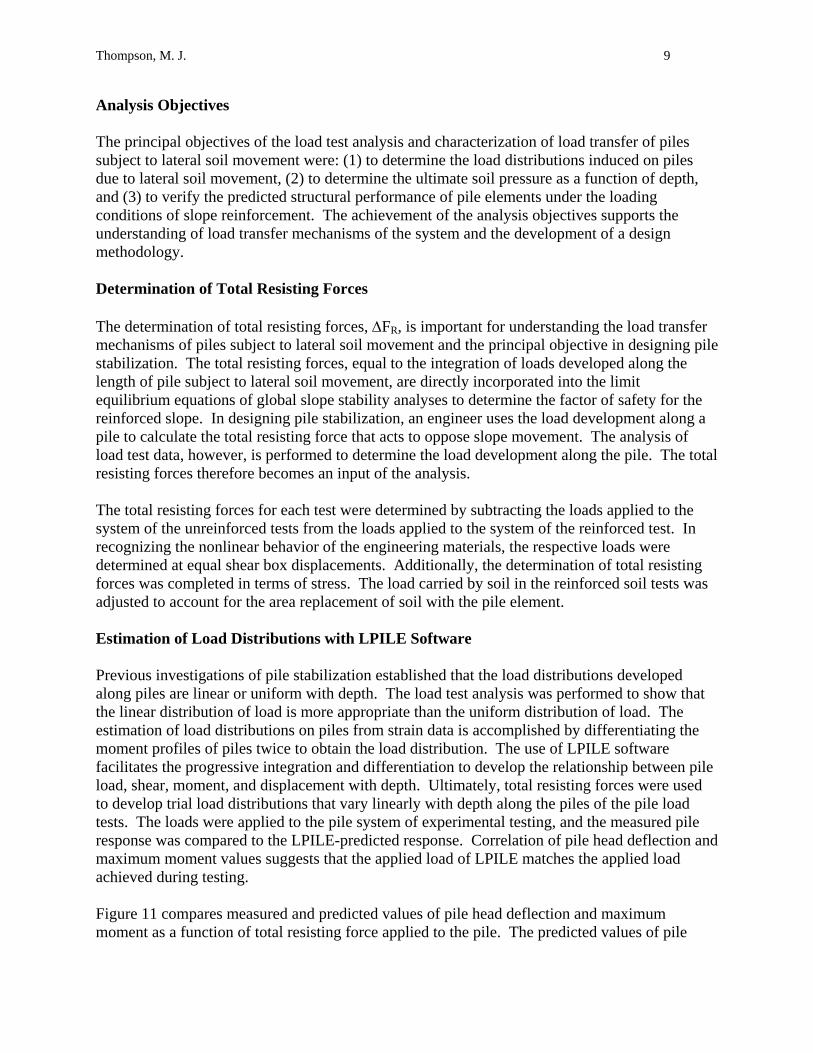
load tests indicated that actual/measured pile diameters were of approximately the same dimension as the augers. The developed concrete mixture was prepared at the testing site and, upon completion of individual boreholes, bottom-fed into the cavity. Estimated concrete slump ranged from 20 cm to 24 cm. Vibration of the material was unnecessary, as intended. Although bottom-feeding the concrete mixture through PVC casing prevented segregation and ensured pile integrity and uniformity, the concrete mixture was principally bottom-fed to avoid placement of grout through a variable water table. Figure 5 shows the placement of grout through the casing. The strength of concrete was verified by performing compression tests on 76-mm-diameter test cylinders. The cylinders from each concrete batch (one batch per pile) were tested on the same day the pile load test was performed. Pile reinforcement was centered in the borehole with spacers and orientated such that strain gauges were facing the tension-side of the piles. Figure 6 shows several shear box forms with compacted soil and steel-reinforced pile elements. The piles remained undisturbed for approximately two weeks following installation so that the concrete mixture developed adequate strength for loading. Pile Load Test Performance The displacement of each shear box was measured with three displacement gauges. Two gauges were mounted to the top of the box (left and right), and one gauge was mounted to the bottom of the box (middle). Use of three gauges to measure displacement provided the data set with redundancy and offered evidence of rotation (about vertical axis) and tilt (about horizontal axis) of the box with continued loading. The instrumentation was mounted on wood reference beams, which were attached to fence posts driven into existing ground outside the zone of influence of the test system. The arrangement for measuring shear box displacements is shown in Figure 7 (a). Displacement gauges were additionally mounted to the section of reinforcement extending above the pile head. The distance between the two gauges was measured, such that the difference in displacement was used to calculate the pile head slope (i.e. rotation) at a given load. The pile head slopes were used to adjust the lower of the displacement gauges for more accurate pile head displacements (i.e. pile head displacement at the soil surface). The use of displacement gauges to measure pile head displacement and slope is shown in Figure 7 (b). Strain of the pile reinforcement was measured concurrent with load and displacement measurements. Strain gauges were installed on the reinforcement at pre-determined elevations, based on moment profiles from preliminary analyses. A total of ten strain gauges were used to define the strain and moment profiles of piles during loading. Each gauge level consisted of a single gauge on the tension-side of the reinforcement. The loading system of the large-scale direct shear tests included a load frame (i.e. pipe struts and steel plates); a pump-controlled, 12-in-stroke hydraulic cylinder; and a load cell. The capacity of the loading system, controlled by the load cell, was 50 kips. The loading system was placed

Thompson, M. J. 7
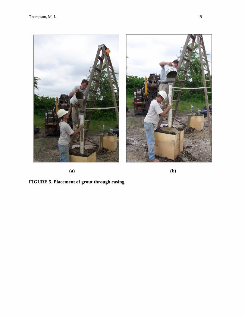
between the shear boxes of a given test, and equivalent loads were simultaneously applied to each shear box by pressurizing the ram cylinder. The electronic deflection measuring devices, the load cell, and strain gauges produced voltage signals that were monitored through an analog-to-digital data acquisition system. The instrumentation was connected to individual terminal channels of the acquisition hardware, and the system software was programmed to record a measurement reading at 3-second intervals. Pile load tests were performed by monitoring shear box displacements and controlling the load applied to each shear box. Generally, load increments of approximately 200 lb were applied to the system, and investigators monitored the displacements of each shear box at the relatively constant load. The next load increment was applied when the rate of displacement for each box became small. Investigators believed that the loading process most accurately offered drained soil behavior, as opposed to undrained soil behavior. The test performance method resulted in loading times between 90 and 180 minutes. After a pile load test was completed, the shear boxes and loading system was disassembled and moved to the next test location. RESULTS Load-Displacement Relationship The measured load-displacement relationships of the shear boxes indicate the contribution of the pile to the shear strength of the system. The difference between the reinforced soil load and the unreinforced soil load, for a given shear box displacement, is the load applied to the pile. The values of total load applied to the pile, ∆FR, are used for estimating the load distributions along the piles with increasing lateral translation of soil. A graph of load vs. displacement for glacial till is shown in Figure 8. Table 1 provides the peak loads of each test and a comparison of the loads with other tests of the same soil. The presented improvement factors are ratios of peak loads for reinforced and unreinforced tests and tests of one and two piles. Moment Profiles A sample moment profile for the entire length of a 112-mm pile in glacial till is shown in Figure 9. The depths of the y-axis are taken from the pile head (at the soil surface), and the loads provided in the legend represent the load applied to the shear box when the moment strains were measured. The loads applied to the pile were subsequently determined for the analysis, in which measured maximum moments were compared with those predicted with LPILE. The figure provides the most influential evidence of flexible pile behavior and pile failure due to mobilization of the pile moment capacity. The maximum measured moments for most single piles exceeded the section moment capacities.

Thompson, M. J. 8
Behavioral Stages of Pile Loading Figures of the relative displacement between shear boxes and pile heads were used to explain the observed pile behavior during the performance of the load tests. Investigators witnessed the formation of a gap at the front (i.e. load-side) of the pile. The gap formed because the displacement of the pile head, due to rotation of the pile, exceeded the displacement of the surface soil. The development of a gap potentially complicated the load test analyses, because the load distribution along the piles was directly affected by the exposed – and therefore, unloaded – length of pile. The figures indicate the behavioral stages of piles subject to lateral soil movement and offer evidence for the mobilization of pile moment capacity. Figure 10 illustrates the behavioral stages, as follows:
Stage 1 – elastic compression of soil and elastic bending of pile Stage 2 – mobilization of soil shear stresses and pile flexural stiffness Stage 3 – incipient failure due to mobilization of pile moment capacity
Stage 1 is characterized by relatively linear behavior of the soil and the intact pile element. The stress development at the soil-pile interface is insufficient to cause yielding of soil or cracking of the pile, such that a gap of negligible width forms. Stage 2 commences with the development of a bending moment in the pile element that causes the tension-carrying concrete to crack. The pile stiffness immediately drops, and the pile element becomes more flexible. Further loading of the pile causes more rapid pile rotation and pile head deflection. Coincidentally, the gap formation occurs more rapidly. Stage 3 commences with the mobilization of the pile moment capacity. The effect of mobilizing the moment capacity of the pile is similar to that associated with the pile cracking of Stage 2. The principal difference between the stages, however, is that the pile rotation which occurs during Stage 3 occurs under constant load. The failed pile element is incapable of carrying additional load. Gaps of significant width form with the mobilization of pile moment capacity and development of a plastic hinge. ANALYTICAL WORK The prediction of pile behavior associated with downslope soil movement is important to the development of the SDGM remediation technology. The potential implementation of the technology requires that design engineers use existing resources (e.g. analytical methods, computer software) to reproduce the response of a pile subject to the loading conditions of slope reinforcement. The development of the SDGM stabilization design methodology, for example, relies on closed-form analytical methods to predict pile behavior including maximum moment and shear forces. The design method also incorporates conventional limit equilibrium methods to determine the factor of safety against slope instability. The research evaluated existing analytical models and the ability of the models to predict pile loading conditions. The research project employed computer software (LPILE) to identify and calibrate the pile response subject to given loading conditions.
Thompson, M. J. 9
Analysis Objectives The principal objectives of the load test analysis and characterization of load transfer of piles subject to lateral soil movement were: (1) to determine the load distributions induced on piles due to lateral soil movement, (2) to determine the ultimate soil pressure as a function of depth, and (3) to verify the predicted structural performance of pile elements under the loading conditions of slope reinforcement. The achievement of the analysis objectives supports the understanding of load transfer mechanisms of the system and the development of a design methodology. Determination of Total Resisting Forces The determination of total resisting forces, ∆FR, is important for understanding the load transfer mechanisms of piles subject to lateral soil movement and the principal objective in designing pile stabilization. The total resisting forces, equal to the integration of loads developed along the length of pile subject to lateral soil movement, are directly incorporated into the limit equilibrium equations of global slope stability analyses to determine the factor of safety for the reinforced slope. In designing pile stabilization, an engineer uses the load development along a pile to calculate the total resisting force that acts to oppose slope movement. The analysis of load test data, however, is performed to determine the load development along the pile. The total resisting forces therefore becomes an input of the analysis. The total resisting forces for each test were determined by subtracting the loads applied to the system of the unreinforced tests from the loads applied to the system of the reinforced test. In recognizing the nonlinear behavior of the engineering materials, the respective loads were determined at equal shear box displacements. Additionally, the determination of total resisting forces was completed in terms of stress. The load carried by soil in the reinforced soil tests was adjusted to account for the area replacement of soil with the pile element. Estimation of Load Distributions with LPILE Software Previous investigations of pile stabilization established that the load distributions developed along piles are linear or uniform with depth. The load test analysis was performed to show that the linear distribution of load is more appropriate than the uniform distribution of load. The estimation of load distributions on piles from strain data is accomplished by differentiating the moment profiles of piles twice to obtain the load distribution. The use of LPILE software facilitates the progressive integration and differentiation to develop the relationship between pile load, shear, moment, and displacement with depth. Ultimately, total resisting forces were used to develop trial load distributions that vary linearly with depth along the piles of the pile load tests. The loads were applied to the pile system of experimental testing, and the measured pile response was compared to the LPILE-predicted response. Correlation of pile head deflection and maximum moment values suggests that the applied load of LPILE matches the applied load achieved during testing. Figure 11 compares measured and predicted values of pile head deflection and maximum moment as a function of total resisting force applied to the pile. The predicted values of pile

Thompson, M. J. 10
head deflection and maximum moment were obtained from the application of a distributed load on the pile varying from zero at the pile head to a maximum value at the failure surface. The measured pile head deflections and maximum moments were obtained from the load test results. DISCUSSION OF LOAD TEST ANALYSIS Comparison of Load Distributions with Existing Analytical Models The load test analysis shows that the load development on piles subject to lateral soil movement varies linearly with depth, as opposed to the development of uniform load distributions on piles as suggested by Broms (1964) and Poulos (1995). Figure 11 illustrates that using linearly distributed loads results in marked correlation between measured and LPILE-predicted values of pile head deflection and maximum moment. The range of loading in LPILE ends at the mobilization of shear or moment capacities of pile sections, such that post-peak behavior was unanalyzed. The implementation of the study findings into a design methodology, nevertheless, focuses on the prediction of service loads which develop prior to failure of soil or pile elements. The prediction of gap formation and post-peak load distributions, although important for understanding pile behavior for the full range of loading, is not important for developing a design methodology based on strength limit states. The principal consequence of failing to mobilize the ultimate soil pressure is the inability to directly deduce the ultimate soil pressure profile with depth. Existing analytical models and the proposed design methodology, however, assume that loads develop along piles as a factored ultimate soil pressure profile. The research established that the loads developed along the piles vary linearly with depth, and the ultimate soil pressure likely varies linearly with depth. Investigators recognize the dependence of ultimate soil pressure on effective stress. Moreover, investigators find that using analytical models which incorporate overburden pressure (e.g. Ito and Matsui, Brinch Hansen) is more appropriate for designing pile stabilization than those models which incorporate only undrained shear strength, based on assumed load distribution profiles of the models. Extension of Pile Performance Prediction for Design of Alternative Pile Sections The ability to accurately predict structural performance of pile sections is important for making stabilization with soil displacement grouted micropiles a robust slope remediation alternative. The benefits of designing piles to be weak or strong, depending on the controlling failure mechanism and required capacity of stabilizing piles, include the design of practical slope reinforcement systems and optimization of the designs to satisfy the cost constraints of the slope remediation. The load test analysis required the validation of the predicted structural performance of the test piles. The analysis objective was achieved, as evidenced by the close correlation between measured maximum moments in failed piles (i.e. moment capacity) and the computed moment capacities of LPILE. Measured pile head deflections and bending behavior, which is highly dependent on pile flexural stiffness (changing with continued loading), was also well predicted

Thompson, M. J. 11
with LPILE. As a result, LPILE is used to reliably analyze and design pile sections with alternative material properties and reinforcement arrangements. SUMMARY It is apparent, from examples in literature and from pile load tests performed at the Iowa State University Spangler Geotechnical Experimentation Site, that small-diameter pile elements provide effective passive resistance to lateral soil movement. Traditional procedures for designing pile stabilization involve the design of large-diameter, heavily-reinforced pile sections; such that the bending moment induced by the application of the ultimate soil pressure does not exceed the moment capacity of the proposed section. An alternative stabilization approach employs small-diameter pile elements, deemed feasible through experimental testing on soil displacement grouted micropiles. The main conclusions developed from the experimental and analytical research study are summarized as follows:
• Loads induced on piles due to lateral soil movement vary linearly with depth. • Ultimate soil pressures were not mobilized during the performance of pile load tests. The
pressure profiles, however, are presumably proportional to the loads induced on piles subject to lateral translation of soil and therefore vary linearly with depth.
• Structural performance of pile elements under the loading conditions of slope reinforcement is effectively predicted with laterally loaded pile software (e.g. LPILE).
The load transfer of piles subject to lateral soil movement associated with unstable slopes has been the focus of international analytical and experimental studies. The results of this research project, however, represent a significant contribution to the ongoing evaluation of pile stabilization. The experimental testing plan, executed in a controlled environment, involved testing full-scale pile elements subject to uniform lateral translation of soil and incorporated three critical parameters of pile stabilization (e.g. soil type, pile size, pile spacing). ACKNOWLEDGEMENTS The Highway Division of the Iowa Department of Transportation and the Iowa Highway Research Board sponsored this study under contract TR-489.

Thompson, M. J. 12
REFERENCES Broms, B. B. (1964). “Lateral resistance of piles in cohesive soil.” Journal of Soil Mechanics and Foundation Division, ASCE, 90(2), 27-63. Ito, T., and T. Matsui (1975). “Methods to estimate lateral force acting on stabilizing piles.” Soils and Foundations, 15 (4), 43-59. Poulos, H. G. (1995). “Design of reinforcing piles to increase slope stability.” Canadian Geotechnical Journal, 37, 890-897. Reese, L. C., W. R. Cox, and F. D. Koop (1974). “Analysis of laterally loaded piles in sand.” Proceedings, 6th Offshore Technology Conference, 2, Houston, TX, 473-483.

Thompson, M. J. 13
LIST OF TABLES TABLE 1. Pile load test plan and peak loads LIST OF FIGURES FIGURE 1. Construction sequence of SDGM system FIGURE 2. Large-scale direct shear test set-up FIGURE 3. Soil compaction in control pads and shear box forms FIGURE 4. Preparation of boreholes FIGURE 5. Placement of grout through casing FIGURE 6. Reinforced soil in shear box forms FIGURE 7. Displacement gauge locations on shear boxes and pile reinforcement FIGURE 8. Graph of load vs. displacement for glacial till (112-mm pile) FIGURE 9. Moment profile for reinforced glacial till (112-mm pile) FIGURE 10. Behavioral stages of piles subject to soil movement FIGURE 11. Measured and predicted pile behavior for 112-mm pile in glacial till

Thompson, M. J. 14
TABLE 1. Pile load test plan and peak loads
Improvement Factors Test
Number Box
Numbers Soil Types Pile Sizes a
Peak Load (kN) Reinforced / Unreinforced
2 Piles / 1 Pile
1 Loess No Pile 1.65 ____ ____ 1 2 Weathered Shale No Pile 5.47 ____ ____ 3 Glacial Till No Pile 4.04 ____ ____
2 4 Loess 114-mm Pile 5.34 3.24 ____ 5 Glacial Till 112-mm Pile 10.45 2.59 ____
3 6 Weathered Shale 117-mm Pile 11.70 2.14 ____ 7 Weathered Shale 114-mm Pile b 6.01 1.10 ____
4 8 Loess 183-mm Pile 6.41 3.88 ____ 9 Glacial Till 178-mm Pile 14.10 3.49 ____
5 10 Weathered Shale (2) 113-mm Piles c 13.96 2.55 1.19 11 Loess (2) 114-mm Piles c 10.94 6.63 2.05
6 12 Weathered Shale 173-mm Pile 17.79 3.25 ____ 13 Glacial Till (2) 113-mm Piles d 16.01 3.96 1.53
7 14 Glacial Till (2) 115-mm Piles c 16.28 4.03 1.56 Notes: All piles with No. 19 rebar a Measured after pile exhumation b No pile reinforcement c Piles in a row d Staggered piles

Thompson, M. J. 15
Steel reinforcement
Zone of compacted
soil
Shear Zone
Soil displaced laterally to
prevent spoil
removal
Grout placed through auger during
extraction
(c)(b)(a)
Grout
FIGURE 1. Construction sequence of SDGM system (a) Displacement of soil due to reverse pitch auger; (b) Placement of grout concurrent with removal of auger; (c) Finished SDGM through failure surface

Thompson, M. J. 16
reinforced pile
steel reinforcement
load beam
61 cm
61 cm
61 cm
pipe strut
steel plates (spacers)
hydraulic cylinder
load cell
FIGURE 2. Large-scale direct shear test set-up

Thompson, M. J. 17
(a)
(b) FIGURE 3. Soil compaction in control pads and shear box forms

Thompson, M. J. 18
(a)
(b) FIGURE 4. Preparation of boreholes
Thompson, M. J. 19
(a) (b) FIGURE 5. Placement of grout through casing

Thompson, M. J. 20
(a)
(b) FIGURE 6. Reinforced soil in shear box forms

Thompson, M. J. 21
(a)
(b)
FIGURE 7. Displacement gauge locations on shear boxes and pile reinforcement

Thompson, M. J. 22
Displacement (cm)
0 3 6 9 12 15
Loa
d (k
N)
0
3
6
9
12
15
ReinforcedUnreinforced
∆FR
FIGURE 8. Graph of load vs. displacement for glacial till (112-mm pile)
Thompson, M. J. 23
Moment (kN-m)
-1 0 1 2 3 4
Dep
th (m
m)
0
300
600
900
1200
1500
1800
2100
0.89 kN4.45 kN5.34 kN6.23 kN7.12 kN8.01 kN8.90 kN9.79 kN
crackedmoment
moment capacity
shear plane
(a)
FIGURE 9. Moment profiles for reinforced glacial till (112-mm pile)

Thompson, M. J. 24
Load (kN)
0 1 2 3 4 5 6
Pile
Hea
d δ
- She
ar B
ox δ
(mm
)
0
10
20
30
40
50
1 2
3
1. Elastic compression of soil and elastic bending of pile
2. Mobilization of soil shear stresses and pile flexural stiffnes
3. Incipient failure due to mobilization of moment capacity of pile
(a)
Shear Box Displacement (cm)
0 5 10 15 20
Pile
Hea
d δ
- She
ar B
ox δ
(mm
)
0
10
20
30
40
50
Slope II:Stage 3 - large gaps formedunder constant load
Note: peak load (approx. 5 kN) achieved at shear box displacement of 5 cm
Slope I:Stages 1 and 2 - smallgaps formed underincreasing load
(b) FIGURE 10. Behavioral stages of piles subject to soil movement (a) Behavioral stages of pile loading; Bilinear rate of gap formation with behavioral stages

Thompson, M. J. 25
Pile Head Deflection (mm)
0 10 20 30 40 50 60
∆F R
(kN
)
0
2
4
6
8
MeasuredLPILE
(a)
∆FR (kN)
0 2 4 6 8
Mm
ax (k
N-m
)
0.0
0.5
1.0
1.5
2.0
2.5
3.0
MeasuredLPILE
(b) FIGURE 11. Measured and predicted pile behavior for 112-mm pile in glacial till (a) Pile head deflections; (b) Maximum moments