LATERAL LOAD ANALYSIS OF SOFT STORY BUILDING AND IMPORTANCE OF MODELING MASONRY INFILL WITH...
8
IJSRD - International Journal for Scientific Research & Development| Vol. 2, Issue 08, 2014 | ISSN (online): 2321-0613 All rights reserved by www.ijsrd.com 228 Lateral Load Analysis of Soft Story Building and Importance of Modeling Masonry Infill with Normalized Strength and Stiffness Ratio Kalappa M Sutar 1 Prof Vishwanath. B. Patil 2 1 P.G student of structural engineering 2 Associate professor 1,2 Department of Civil Engineering 1,2 P D A C E, Gulbarga Abstract— Generally Masonry infills are considered as non- structural elements and their stiffness contributions are generally ignored in practice. But they affect both the structural and non-structural performance of the RC buildings during earthquakes. RC frame building with open first storey is known as soft storey, which performs poorly during strong earthquake shaking. A similar soft storey effect can occur if first and second story used as service story. Hence a combination of two structural system components i.e. Rigid frames and RC shear walls leads to a highly efficient system in which shear wall resist the majority of the lateral loads and the frame supports majority of the gravity loads. To study the effect of masonry infill with different soft storey level, 7 models of Reinforced Concrete framed building were analyzed with two types of shear wall when subjected to earthquake loading. The results of bare frame and other building models have been compared, it is observed that model with swastika and L shape shear wall are showing efficient performance and hence reducing the effect of soft storey in model 3, model 4 and model 5. Keywords: Equivalent strut, Masonry infill, shear wall, soft storey I. INTRODUCTION Many urban multistorey buildings in India today have open first storey as an unavoidable feature. This leave the open first storey of masonry infilled reinforced concrete frame building primarily to generate parking or reception lobbies in the first storey. It has been known for long time that masonry infill walls affect the strength & stiffness of infilled frame structures. There are plenty of researches done so far for infilled frames, however partially infill frames are still the topic of interest. Though it has been understood that the infill’s play significant role in enhancing the lateral stiffness of complete structures.Infills have been generally considered as non-structural elements & their influence was neglected during the modeling phase of the structure. A soft storey building is a multi-storey building with one or more floors which are “soft” due to structural design. These floors can be especially dangerous in earthquakes. As a result, the soft storey may fail, causing what is known as a soft storey collapse. Soft storey buildings are characterized by having a storey which has a lot of open space. Parking garages, for example, are often soft stories, as are large retail spaces or floors with a lot of windows. While the unobstructed space of the soft storey might be aesthetically or commercially desirable, it also means that there are less opportunities to install shear walls, specialized walls which are designed to distribute lateral forces. If a building has a floor which is 70% less stiff than the floor above it, it is considered a soft storey building. This soft storey creates a major weak point in an earthquake, and since soft stories are classically associated with reception lobbies retail spaces and parking garages. Reinforced concrete (RC) structural walls, conventionally known as shear walls are effective in resisting lateral loads imposed by wind or earthquakes. They provide substantial strength and stiffness as well as the deformation capacity (capacity to dissipate energy) needed for tall structures to meet seismic demand. It has become increasingly common to combine the moment resisting framed structure for resisting gravity loads and the RC shear walls for resisting lateral loads in tall building structures. The consequence of the presence of a soft storey either in the ground storey or in the upper storey, may lead to a dangerous sway mechanism in the soft storey due to formation of plastic hinges at the top and bottom end of the columns, as these columns are subjected to relatively large cyclic deformations. The main Objectives of the present study is (1) To know the effect of infill in the frame. (2) To know proper modeling technique of masonry infill. (3) To check the strength and stiffness of each storey. (4) To know the effect of ground and successive soft storey level. II. DESCRIPTION OF STRUCTURAL MODEL The study has done on 7 different models of an eleven storey building are considered the building has five bays in X direction and five bays in Y direction with the plan dimension 25 m × 20 m and a storey height of 3.5 m each in all the floors. The building is kept symmetric in both mutually perpendicular directions in plan to avoid torsional effects. The orientation and size of column is kept same throughout the height of the structure. The building is considered to be located in seismic zone V. The building is founded on medium strength soil through isolated footing under the columns. Elastic modules of concrete and masonry are taken as 27386 MPa and 3500 MPa respectively and their poisons ratio as 0.20 and 0.15 respectively. Response reduction factor for the special moment resisting frame has taken as 5.0 (assuming ductile detailing). The unit weights of concrete and masonry are taken as 25.0 KN/m 3 and 20.0 KN/m 3 respectively the floor finish on the floors is 1.5 KN/m 2 . The live load on floor is taken as 3.5 KN/m 2 . In seismic weight calculations, 50 % of the floor live loads are considered. Thickness of Slab, shear wall and masonry infill wall as 0.125m, 0.2 m and 0.23m respectively.
Transcript of LATERAL LOAD ANALYSIS OF SOFT STORY BUILDING AND IMPORTANCE OF MODELING MASONRY INFILL WITH...

IJSRD - International Journal for Scientific Research & Development| Vol. 2, Issue 08, 2014 | ISSN (online): 2321-0613
All rights reserved by www.ijsrd.com 228
Lateral Load Analysis of Soft Story Building and Importance of
Modeling Masonry Infill with Normalized Strength and Stiffness Ratio Kalappa M Sutar
1 Prof Vishwanath. B. Patil
2
1P.G student of structural engineering
2Associate professor
1,2Department of Civil Engineering
1,2P D A C E, Gulbarga
Abstract— Generally Masonry infills are considered as non-
structural elements and their stiffness contributions are
generally ignored in practice. But they affect both the
structural and non-structural performance of the RC
buildings during earthquakes. RC frame building with open
first storey is known as soft storey, which performs poorly
during strong earthquake shaking. A similar soft storey
effect can occur if first and second story used as service
story. Hence a combination of two structural system
components i.e. Rigid frames and RC shear walls leads to a
highly efficient system in which shear wall resist the
majority of the lateral loads and the frame supports majority
of the gravity loads. To study the effect of masonry infill
with different soft storey level, 7 models of Reinforced
Concrete framed building were analyzed with two types of
shear wall when subjected to earthquake loading. The results
of bare frame and other building models have been
compared, it is observed that model with swastika and L
shape shear wall are showing efficient performance and
hence reducing the effect of soft storey in model 3, model 4
and model 5.
Keywords: Equivalent strut, Masonry infill, shear wall, soft
storey
I. INTRODUCTION
Many urban multistorey buildings in India today have open
first storey as an unavoidable feature. This leave the open
first storey of masonry infilled reinforced concrete frame
building primarily to generate parking or reception lobbies
in the first storey. It has been known for long time that
masonry infill walls affect the strength & stiffness of infilled
frame structures. There are plenty of researches done so far
for infilled frames, however partially infill frames are still
the topic of interest. Though it has been understood that the
infill’s play significant role in enhancing the lateral stiffness
of complete structures.Infills have been generally considered
as non-structural elements & their influence was neglected
during the modeling phase of the structure. A soft storey
building is a multi-storey building with one or more floors
which are “soft” due to structural design. These floors can
be especially dangerous in earthquakes. As a result, the soft
storey may fail, causing what is known as a soft storey
collapse. Soft storey buildings are characterized by having a
storey which has a lot of open space. Parking garages, for
example, are often soft stories, as are large retail spaces or
floors with a lot of windows. While the unobstructed space
of the soft storey might be aesthetically or commercially
desirable, it also means that there are less opportunities to
install shear walls, specialized walls which are designed to
distribute lateral forces. If a building has a floor which is
70% less stiff than the floor above it, it is considered a soft
storey building. This soft storey creates a major weak point
in an earthquake, and since soft stories are classically
associated with reception lobbies retail spaces and parking
garages.
Reinforced concrete (RC) structural walls,
conventionally known as shear walls are effective in
resisting lateral loads imposed by wind or earthquakes. They
provide substantial strength and stiffness as well as the
deformation capacity (capacity to dissipate energy) needed
for tall structures to meet seismic demand. It has become
increasingly common to combine the moment resisting
framed structure for resisting gravity loads and the RC shear
walls for resisting lateral loads in tall building structures.
The consequence of the presence of a soft storey either in
the ground storey or in the upper storey, may lead to a
dangerous sway mechanism in the soft storey due to
formation of plastic hinges at the top and bottom end of the
columns, as these columns are subjected to relatively large
cyclic deformations.
The main Objectives of the present study is
(1) To know the effect of infill in the frame.
(2) To know proper modeling technique of masonry
infill.
(3) To check the strength and stiffness of each storey.
(4) To know the effect of ground and successive soft
storey level.
II. DESCRIPTION OF STRUCTURAL MODEL
The study has done on 7 different models of an eleven
storey building are considered the building has five bays in
X direction and five bays in Y direction with the plan
dimension 25 m × 20 m and a storey height of 3.5 m each in
all the floors. The building is kept symmetric in both
mutually perpendicular directions in plan to avoid torsional
effects. The orientation and size of column is kept same
throughout the height of the structure. The building is
considered to be located in seismic zone V. The building is
founded on medium strength soil through isolated footing
under the columns. Elastic modules of concrete and masonry
are taken as 27386 MPa and 3500 MPa respectively and
their poisons ratio as 0.20 and 0.15 respectively. Response
reduction factor for the special moment resisting frame has
taken as 5.0 (assuming ductile detailing). The unit weights
of concrete and masonry are taken as 25.0 KN/m3 and 20.0
KN/m3 respectively the floor finish on the floors is 1.5
KN/m2. The live load on floor is taken as 3.5 KN/m
2. In
seismic weight calculations, 50 % of the floor live loads are
considered. Thickness of Slab, shear wall and masonry infill
wall as 0.125m, 0.2 m and 0.23m respectively.

Lateral Load Analysis of Soft Story Building and Importance of Modeling Masonry Infill with Normalized Strength and Stiffness Ratio
(IJSRD/Vol. 2/Issue 08/2014/052)
All rights reserved by www.ijsrd.com 229
III. MODEL CONSIDERED FOR ANALYSIS
Following fourteen (7) models are analyzed in ETABS9.7 as
special moment resisting frame using equivalent static
analysis, response spectrum analysis.
Model 1: Bare frame model, however masses of
brick masonry infill walls (230mm thick) are included in the
model.
Model 2: Building model has full brick masonry
infill of 230mm thick in all the stories.
Model 3: Building model has no brick masonry
infill in ground storey and has full brick masonry infill of
230mm thick in upper stories.
Model 4: Building model has no brick masonry
infill wall in ground and first story and has full brick
masonry infill in rest of the storeys.
Model 5: Building model has no brick masonry
infill in ground, first and second storey and has full brick
masonry infill in rest of all storeys.
Model 6: Building model has no brick masonry
infill in ground, first and second storey. Further, swastika
type of shear wall (200mm thick) is provided at corners.
Model 7: Building model is same as model
5.Further, L shaped shear wall (200mm thick) is provided in
both x and y direction.
Fig. 1: Plan and Elevation of different building models with
infill panel.
First set of models have been prepared while
considering masonry infill as four noded quadrilateral shell
element and second set is prepared while masonry infill is
modelled as equivalent double diagonal strut.
Fig. 2: Elevation of different building models
IV. MODELING OF FRAME MEMBERS, AND SHEAR WALL
The frame elements are modelled as beam elements, slab is
modelled as rigid (in-plane) diaphragm and shear wall is
modelled with Mid-Pier frame.
V. MODELLING OF MASONRY INFILL IN ETABS
A. As Four Noded Quadrilateral shell element
In this technique the masonry infill is modelled as four
noded quadrilateral shell element (with in-plane stiffness) of
uniform thickness of 0.23mm. The four-node element uses
an Iso-parametric formulation that includes both rotational
and translational degrees of freedom. (Ref fig 1)
Fig. 3: Four Noded Quadrilateral Element.
B. As Equivalent Double diagonal strut
The frames with unreinforced masonry walls can also be
modelled as equivalent braced frames with infill walls
replaced by equivalent diagonal strut. Many investigators
have proposed various approximations for the width of
equivalent diagonal strut. The width of strut depends on the
length of contact between the wall & the columns (αh) and
between the wall & the beams (αL). The formulations for αh
and αL on the basis of beam on an elastic foundation has
been used given by Stafford Smith (1966). Hendry (1998)
proposed the following equation to determine the equivalent
or effective strut width w, where the strut is assumed to be
subjected to uniform compressive stress.
h =
√
(1)
L = π √
(2)
w =
√ (3)
Where Em is elastic modulus of masonry wall, Ef is
elastic modulus of frame material, t is thickness of infill, h is
height of infill and L is length of infill, Ic is moment of
inertia of the column, Ib is moment of inertia of the beam
and θ = tan-1 (h/L).
Lateral Load Analysis of Soft Story Building and Importance of Modeling Masonry Infill with Normalized Strength and Stiffness Ratio
(IJSRD/Vol. 2/Issue 08/2014/052)
All rights reserved by www.ijsrd.com 230
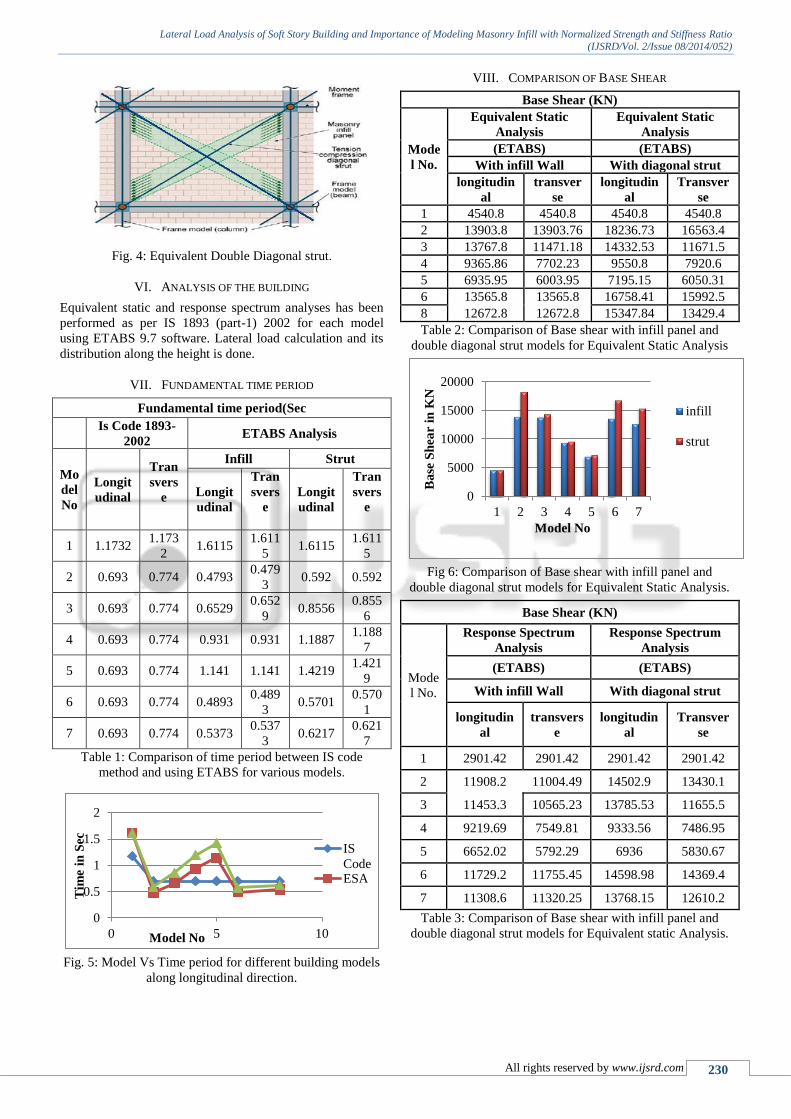
Fig. 4: Equivalent Double Diagonal strut.
VI. ANALYSIS OF THE BUILDING
Equivalent static and response spectrum analyses has been
performed as per IS 1893 (part-1) 2002 for each model
using ETABS 9.7 software. Lateral load calculation and its
distribution along the height is done.
VII. FUNDAMENTAL TIME PERIOD
Fundamental time period(Sec
Is Code 1893-
2002 ETABS Analysis
Mo
del
No
Longit
udinal
Tran
svers
e
Infill Strut
Longit
udinal
Tran
svers
e
Longit
udinal
Tran
svers
e
1 1.1732 1.173
2 1.6115
1.611
5 1.6115
1.611
5
2 0.693 0.774 0.4793 0.479
3 0.592 0.592
3 0.693 0.774 0.6529 0.652
9 0.8556
0.855
6
4 0.693 0.774 0.931 0.931 1.1887 1.188
7
5 0.693 0.774 1.141 1.141 1.4219 1.421
9
6 0.693 0.774 0.4893 0.489
3 0.5701
0.570
1
7 0.693 0.774 0.5373 0.537
3 0.6217
0.621
7
Table 1: Comparison of time period between IS code
method and using ETABS for various models.
Fig. 5: Model Vs Time period for different building models
along longitudinal direction.
VIII. COMPARISON OF BASE SHEAR
Base Shear (KN)
Mode
l No.
Equivalent Static
Analysis
Equivalent Static
Analysis
(ETABS) (ETABS)
With infill Wall With diagonal strut
longitudin
al
transver
se
longitudin
al
Transver
se
1 4540.8 4540.8 4540.8 4540.8
2 13903.8 13903.76 18236.73 16563.4
3 13767.8 11471.18 14332.53 11671.5
4 9365.86 7702.23 9550.8 7920.6
5 6935.95 6003.95 7195.15 6050.31
6 13565.8 13565.8 16758.41 15992.5
8 12672.8 12672.8 15347.84 13429.4
Table 2: Comparison of Base shear with infill panel and
double diagonal strut models for Equivalent Static Analysis
Fig 6: Comparison of Base shear with infill panel and
double diagonal strut models for Equivalent Static Analysis.
Base Shear (KN)
Mode
l No.
Response Spectrum
Analysis
Response Spectrum
Analysis
(ETABS) (ETABS)
With infill Wall With diagonal strut
longitudin
al
transvers
e
longitudin
al
Transver
se
1 2901.42 2901.42 2901.42 2901.42
2 11908.2 11004.49 14502.9 13430.1
3 11453.3 10565.23 13785.53 11655.5
4 9219.69 7549.81 9333.56 7486.95
5 6652.02 5792.29 6936 5830.67
6 11729.2 11755.45 14598.98 14369.4
7 11308.6 11320.25 13768.15 12610.2
Table 3: Comparison of Base shear with infill panel and
double diagonal strut models for Equivalent static Analysis. 0
0.5
1
1.5
2
0 5 10
Tim
e in
Sec
Model No
IS
CodeESA
0
5000
10000
15000
20000
1 2 3 4 5 6 7
Ba
se S
hea
r in
KN
Model No
infill
strut
Lateral Load Analysis of Soft Story Building and Importance of Modeling Masonry Infill with Normalized Strength and Stiffness Ratio
(IJSRD/Vol. 2/Issue 08/2014/052)
All rights reserved by www.ijsrd.com 231
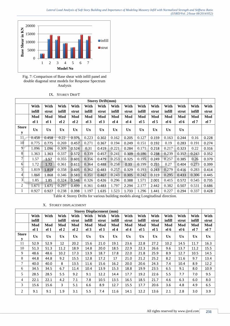
Fig. 7: Comparison of Base shear with infill panel and
double diagonal strut models for Response Spectrum
Analysis
IX. STOREY DRIFT
Storey Drift(mm)
With
infill
With
strut
With
infill
With
strut
With
infill
With
strut
With
infill
With
strut
With
infill
With
strut
With
infill
With
strut
With
infill
With
strut
Mod
el 1
Mod
el 1
Mod
el 2
Mod
el 2
Mod
el 3
Mod
el 3
Mod
el 4
Mod
el 4
Mod
el 5
Mod
el 5
Mod
el 6
Mod
el 6
Mod
el 7
Mod
el 7
Store
y Ux Ux Ux Ux Ux Ux Ux Ux Ux Ux Ux Ux
11 0.458 0.458 0.22 0.375 0.223 0.302 0.162 0.205 0.127 0.159 0.163 0.244 0.16 0.228
10 0.775 0.775 0.269 0.457 0.271 0.367 0.194 0.249 0.151 0.192 0.19 0.283 0.191 0.274
9 1.096 1.096 0.309 0.524 0.31 0.419 0.221 0.284 0.171 0.218 0.217 0.323 0.22 0.316
8 1.363 1.363 0.337 0.572 0.339 0.457 0.241 0.309 0.186 0.238 0.239 0.357 0.243 0.352
7 1.57 1.57 0.355 0.601 0.356 0.479 0.253 0.325 0.195 0.249 0.257 0.385 0.26 0.379
6 1.72 1.72 0.361 0.611 0.364 0.488 0.258 0.33 0.199 0.255 0.27 0.404 0.273 0.399
5 1.819 1.819 0.358 0.605 0.362 0.483 0.257 0.329 0.193 0.243 0.279 0.416 0.283 0.414
4 1.868 1.868 0.346 0.583 0.351 0.467 0.243 0.305 0.242 0.319 0.295 0.433 0.306 0.445
3 1.85 1.85 0.324 0.546 0.326 0.426 0.296 0.388 1.571 2.001 0.415 0.572 0.545 0.735
2 1.671 1.671 0.297 0.499 0.361 0.483 1.797 2.294 2.177 2.442 0.382 0.507 0.531 0.686
1 0.927 0.927 0.238 0.398 1.197 1.635 1.523 1.733 1.296 1.441 0.227 0.294 0.337 0.428
Table 4: Storey Drifts for various building models along Longitudinal direction.
X. STOREY DISPLACEMENT
Storey Displacement (mm)
With
infill
With
strut
With
infill
With
strut
With
infill
With
strut
With
infill
With
strut
With
infill
With
strut
With
infill
With
strut
With
infill
With
strut
Mod
el 1
Mod
el 1
Mod
el 2
Mod
el 2
Mod
el 3
Mod
el 3
Mod
el 4
Mod
el 4
Mod
el 5
Mod
el 5
Mod
el 6
Mod
el 6
Mod
el 7
Mod
el 7
Store
y Ux Ux Ux Ux Ux Ux Ux Ux Ux Ux Ux Ux Ux Ux
11 52.9 52.9 12 20.2 15.6 21.0 19.1 23.6 22.8 27.2 10.2 14.5 11.7 16.3
10 51.3 51.3 11.2 18.9 14.8 20.0 18.5 22.9 22.3 26.6 9.6 13.7 11.2 15.5
9 48.6 48.6 10.2 17.3 13.9 18.7 17.8 22.0 21.8 25.9 8.9 12.7 10.5 14.5
8 44.8 44.8 9.2 15.5 12.8 17.2 17 21.0 21.2 25.2 8.2 11.6 9.7 13.4
7 40.0 40.0 8 13.5 11.6 15.6 16.2 20.0 20.6 24.3 7.4 10.4 8.9 12.2
6 34.5 34.5 6.7 11.4 10.4 13.9 15.3 18.8 19.9 23.5 6.5 9.1 8.0 10.9
5 28.5 28.5 5.5 9.2 9.1 12.2 14.4 17.7 19.2 22.6 5.5 7.7 7.0 9.5
4 22.1 22.1 4.2 7.1 7.8 10.5 13.5 16.5 18.5 21.7 4.6 6.3 6.0 8.0
3 15.6 15.6 3 5.1 6.6 8.9 12.7 15.5 17.7 20.6 3.6 4.8 4.9 6.5
2 9.1 9.1 1.9 3.1 5.5 7.4 11.6 14.1 12.2 13.6 2.1 2.8 3.0 3.9
0
5000
10000
15000
20000
1 2 3 4 5 6 7
Ba
se S
hea
r in
KN
Model No
infill
strut
Lateral Load Analysis of Soft Story Building and Importance of Modeling Masonry Infill with Normalized Strength and Stiffness Ratio
(IJSRD/Vol. 2/Issue 08/2014/052)
All rights reserved by www.ijsrd.com 232
1 3.2 3.2 0.8 1.4 4.2 5.2 5.3 6.1 4.5 5.0 0.8 1.0 1.2 1.5 Table 5: Storey Displacement for various building models along longitudinal direction
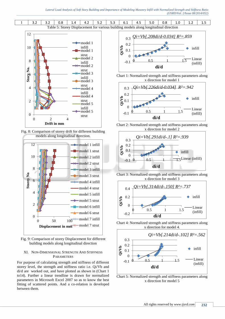
Fig. 8: Comparison of storey drift for different building
models along longitudinal direction.
Fig. 9: Comparison of storey Displacement for different
building models along longitudinal direction
XI. NON-DIMENSIONAL STRENGTH AND STIFFNESS
PARAMETERS
For purpose of calculating strength and stiffness of different
storey level, the strength and stiffness ratio i.e. Qi/Vb and
di/d are worked out, and have plotted as shown in (Chart 1
to14). Further a linear trendline is drawn for normalized
parameters in Microsoft Excel 2007 so as to know the best
fitting of scattered points. And a co-relation is developed
between them.
Chart 1: Normalized strength and stiffness parameters along
x direction for model 1
Chart 2: Normalized strength and stiffness parameters along
x direction for model 2
Chart 3: Normalized strength and stiffness parameters along
x direction for model 3
Chart 4: Normalized strength and stiffness parameters along
x direction for model 4.
Chart 5: Normalized strength and stiffness parameters along
x direction for model 5
0
2
4
6
8
10
12
0 2 4
Sto
ry N
o.
Drift in mm
model 1
infillmodel 1
strutmodel 2
infillmodel 2
strutmodel 3
infillmodel 3
strutmodel 4
infillmodel 4
strutmodel 5
infillmodel 5
strut
0
2
4
6
8
10
12
0 50 100
Sto
rey
No
Displacement in mm
model 1 infill
model 1 strut
model 2 infill
model 2 strut
model 3 infill
model 3 strut
model 4 infill
model 4 strut
model 5 infill
model 5 strut
model 6 infill
model 6 strut
model 7 infill
model 7 strut
-0.1
0
0.1
0.2
0.3
0 0.5 1 1.5
Qi/
Vb
di/d
Qi=Vb[.208di/d-0.034] R²=.859
infill
Linear
(infill)
-0.1
0
0.1
0.2
0.3
0 0.5 1 1.5
Qi/
Vb
di/d
Qi=Vb[.226di/d-0.034] R²=.942
infill
Linear
(infill)
-0.1
0
0.1
0.2
0.3
0 0.5 1 1.5
Qi/
Vb
di/d
Qi=Vb[.291di/d-.1] R²=.939
infill
Linear (infill)
-0.2
0
0.2
0.4
0 0.5 1 1.5
Qi/
Vb
di/d
Qi=Vb[.314di/d-.150] R²=.737
infill
Linear
(infill)
-0.1
0
0.1
0.2
0.3
0 0.5 1 1.5
Qi/
Vb
di/d
Qi=Vb[.214di/d-.102] R²=.562
infill
Linear
(infill)

Lateral Load Analysis of Soft Story Building and Importance of Modeling Masonry Infill with Normalized Strength and Stiffness Ratio
(IJSRD/Vol. 2/Issue 08/2014/052)
All rights reserved by www.ijsrd.com 233
Chart 6: Normalized strength and stiffness parameters along
x direction for model 6
Chart 7: Normalized strength and stiffness parameters along
x direction for model 7
Chart 8: Normalized strength and stiffness parameters along
x direction for model 1.
Chart 9: Normalized strength and stiffness parameters along
x direction for model 2.
Chart 10: Normalized strength and stiffness parameters
along x direction for model 3.
Chart 11: Normalized strength and stiffness parameters
along x direction for model 4
Chart 12: Normalized strength and stiffness parameters
along x direction for model 5.
Chart 13: Normalized strength and stiffness parameters
along x direction for model 6.
Chart 14: Normalized strength and stiffness parameters
along x direction for model 7
XII. RESULTS AND DISCUSSIONS
Table 1 shows natural time period, for bare frame model,
from ETABS, it is 27.19 more than the IS code method.
When the structural action of masonry infill is taken the
fundamental natural time got reduced 70.25% when
compare with bare frame model, The soft storeys mode 3,
model 4, model 5 the increase time period 26.58%,
48.15%,57.99. The time period get reduces for shear wall
model 6, model 7 is 57.11%, 52.90%. the time period
-0.1
0
0.1
0.2
0.3
0 1 2
Qi/
Vb
di/d
Qi=Vb[.237di/d-.052] R²=.904
infill
Linear
(infill)
-0.1
0
0.1
0.2
0.3
0 0.5 1 1.5
Qi/
Vb
di/d
Qi=Vb[.245di/d-0.065] R²=.876
infill
Linear
(infill)
-0.2
0
0.2
0.4
0 0.5 1 1.5
Qi/
Vb
di/d
Qi=Vb[.208di/d-0.034] R²=.859
strut
Linear
(strut)
-0.5
0
0.5
0 0.5 1 1.5Qi/
Vb
di/d
Qi=Vb[.224di/d-0.032] R²=.933
strut
Linear
(strut)
-0.1
0
0.1
0.2
0.3
0 0.5 1 1.5
Qi/
Vb
di/d
Qi= Vb[0.284di/d-0.094] R²=0.925
strut
Linear
(strut)
-0.1
0
0.1
0.2
0.3
0 0.5 1 1.5
Qi/
Vb
di/d
Qi=Vb[0.303di/d-0.140] R²=.734
strut
Linear
(strut)
-0.1
0
0.1
0.2
0.3
0 0.5 1 1.5
Qi/
Vb
di/d
Qi=Vb[0.239di/d-0.098] R²=0.580
strut
Linear (strut)
-0.1
0
0.1
0.2
0.3
0 0.5 1 1.5
Qi/
Vb
di/d
Qi=Vb[0.234di/d-0.048] R²=0.904
strut
Linear (strut)
-0.1
0
0.1
0.2
0.3
0 0.5 1 1.5
Qi/
Vb
di/d
Qi=Vb[0.242di/d-0.060] R²=0.881
strut
Linear (strut)

Lateral Load Analysis of Soft Story Building and Importance of Modeling Masonry Infill with Normalized Strength and Stiffness Ratio
(IJSRD/Vol. 2/Issue 08/2014/052)
All rights reserved by www.ijsrd.com 234
reduction in double diagonal strut little more compared to
infill panel. [Ref table 1 and Fig 5]
Seismic base shear obtained for double diagonal
strut models are considerably higher than infill panel models
for ESA and RSA in both the directions. [Ref table 2and 3
Fig 6,7]
Storey drift drastically increased when a successive
soft storey is exist, for model 5 at ground, first, second
storey level it is increased by 86.35% in case of infill panel
and 79.56% in case of double diagonal strut as compared
with Model 2. Shear walls of different shapes drastically
reduces the inter storey drift. [Refer table 4 Fig 8]
Model1(bare frame) model shows highest storey
displacement values in all different building models model 2
(full brick infill) shows considerable reduction in storey
displacement with a maximum reduction of 77.31% in case
of masonry infill panel and 61.81% in case of double
diagonal strut as compared with model 1 and model 6,
model 7 shows 80.71% and 77.88% reduction in
displacement value compared with model 1. [Refer table 5,
Fig 9]
Thus it can be concluded that addition of infill and
concrete shear wall act as drift and displacement controlled
elements in RC buildings.
Chart 1 to 14 shows the normalized Strength and
stiffness ratios, R2 value for bare frame model is least as
compared to all other models which shows the frame is very
much flexible in nature and susceptible earthquake
threatening. Ground and successive soft storey model 5
shows least strength and stiffness ratio which leads to
dangerous sway mechanism. Ground and successive soft
storey models shows scattering of points and not fitting a
good curve. Model 2 and 6, 7 shows the best fit, which
means it has got sufficient strength and stiffness to resist
seismic loading. Models with double diagonal strut are
showing slightly lesser R2 values than models with infill
panel which shows double diagonal strut models are flexible
than masonry infill panel.
XIII. CONCLUSIONS
Fundamental time period decreases when the effect
of masonry infill wall and concrete shear and core
wall is considered.
IS Code method gives same time period for
masonry infill and shear wall models, when time
period calculated by ETABS is different for
different models. So that the software like ETABS
must be used to calculate fundamental natural time
period of structure.
Double diagonal strut models are showing large
time period as compared with infill panel model.
Seismic base shear is considerably more for
masonry infill and shear wall models as compared
with bare frame model and storey drifts and joint
displacements considerably reduces, Hence
consideration of masonry infill and shear wall will
increases strength and stiffness of structure when
subjected to lateral seismic loading.
Models with successive soft stories have got
highest storey drift values at soft stories levels,
which leads to dangerous sway mechanism.
Therefore providing shear wall is essential so as to
avoid soft storey failure.
Masonry infill panel models are showing much
strength and stiffness as compared with double
diagonal strut models, therefore masonry infill
panel can be a good solution to model masonry
infill. And therefore depending upon the
importance of structure and type of design it has to
be modeled.
From the non-dimensional analysis it is observed
that for full masonry infill and shear wall models,
R2
value is nearly equal to 1, which means each
storey has got sufficient strength and stiffness to
resist lateral seismic loading.
The non dimensional analysis shows the R2 value is
lesser than the bare frame model for successive soft
storeyes model 4, 5. Which means that strength and
stiffness for each soft storey less has got reduced.
REFERENCE
[1] P. S. Kumbhare1, A. C. Saoji2“Effectiveness of
Changing Reinforced Concrete Shear Wall Location
on Multi-storeyed Building” Internaional Journal of
Engineering Research and application (IJSERA)
ISSN:2248-9612. www.ijera.com volum.2, Issue-4
septmber – October 2012,
[2] Jaswant N. Arlekar, Sudhir K. Jain and C.V.R.
Murty“Seismic Response of RC Fram Buildings with
Soft First Storeys” Department of Civil Engineering,
I.I.T.Kanpur, Kanpur 208016Proceedings of the
CBRI Golden Jubilee Conference on Natural Hazards
in Urban Habitat, 1997, New Delhi.
[3] Rahiman G. Khan , Prof. M. R. Vyawahare, “Push
Over Analysis of Tall Building with Soft Stories at
Different Levels”,International Journal of
Engineering Research and Applications (IJERA)
ISSN: 2248-9622 www.ijera.com Vol. 3, Issue 4, Jul-
Aug 2013, pp.176-185.
[4] M.R. Amin, P. Hasan ”Effect of soft storey on
multistoried reinforced concrete building
frame”University of Asia Pacific, 4th Annual Paper
Meet and 1st Civil Engineering Congress, December
22-24, 2011, Dhaka, Bangladesh
[5] Nikhil Agrawal, P.B Kulkarni and Pooja Raut.
“Analysis of Masonry Infilled R.C. Frame with &
without Opening Including Soft Storey using
Equivalent Diagonal Strut Method”,International
Journal of Scientific and Research Publications,
Volume 3, Issue 9, September 2013 1 ISSN 2250-
3153.
[6] Misam Abidi, Mangulkar Madhuri“Structural
Response Of Soft Story-High Rise Buildings Under
Different Shear Wall Location”IJCIET Volume 3,
Issue 2, July-December (2012), pp. 169-180
[7] Munde P. K., Magarpatil H.R“Seismic Response of
Rc Framed Masonry Infilled Buildings With Soft
First Storey”Vol. 1 Issue 9, November- 2012(IJERT)
[8] Amit V. Khandve. “Seismic Response of RC Frame
Buildings with Soft Storeys”. International Journal of
Engineering Research and Applications (IJERA)
ISSN: 2248-9622 www.ijera.com Vol. 2, Issue 3,
May-Jun 2012, pp.2100-2108
Lateral Load Analysis of Soft Story Building and Importance of Modeling Masonry Infill with Normalized Strength and Stiffness Ratio
(IJSRD/Vol. 2/Issue 08/2014/052)
All rights reserved by www.ijsrd.com 235
[9] IS 1893(Part-I) 2002: Criteria for Earthquake
Resistant Design of Structures, Part-I General
Provision and Buildings (Fifth Revision).Bureau of
Indian Standards, New Delhi.
[10] [IS 456: 2000. “Indian Standard Code of Practice for
plain and reinforced Concrete”, Bureau of Indian
Standards, New Delhi.
[11] ETABS Non-linear 9.7.Computers and Structures Inc,
Berkeley.