LASERJET ENTERPRISE MFP M630 - HP User Training
56
LASERJET ENTERPRISE MFP M630 Maintenance kit replacement manual M630dn M630f M630z M630h Copyright and License © 2014 Copyright Hewlett-Packard Development Company, L.P. Reproduction, adaptation, or translation without prior written permission is prohibited, except as allowed under the copyright laws. The information contained herein is subject to change without notice. The only warranties for HP products and services are set forth in the express warranty statements accompanying such products and services. Nothing herein should be construed as constituting an additional warranty. HP shall not be liable for technical or editorial errors or omissions contained herein. Edition 1, 9/2014
Transcript of LASERJET ENTERPRISE MFP M630 - HP User Training
LASERJET ENTERPRISE MFP M630
Maintenance kit replacement manual
M630dn M630f M630z
M630h
Copyright and License
© 2014 Copyright Hewlett-Packard Development Company, L.P.
Reproduction, adaptation, or translation without prior written
permission is prohibited, except as allowed under the copyright
laws.
The information contained herein is subject to change without
notice.
The only warranties for HP products and services are set forth in
the express warranty statements accompanying such products and
services. Nothing herein should be
construed as constituting an additional
warranty. HP shall not be liable for
technical or editorial errors or omissions
contained herein.
Edition 1, 9/2014
Trademark Credits
Microsoft®, Windows®,
Windows® XP, and Windows
Vista® are U.S. registered
trademarks of Microsoft
Corporation.
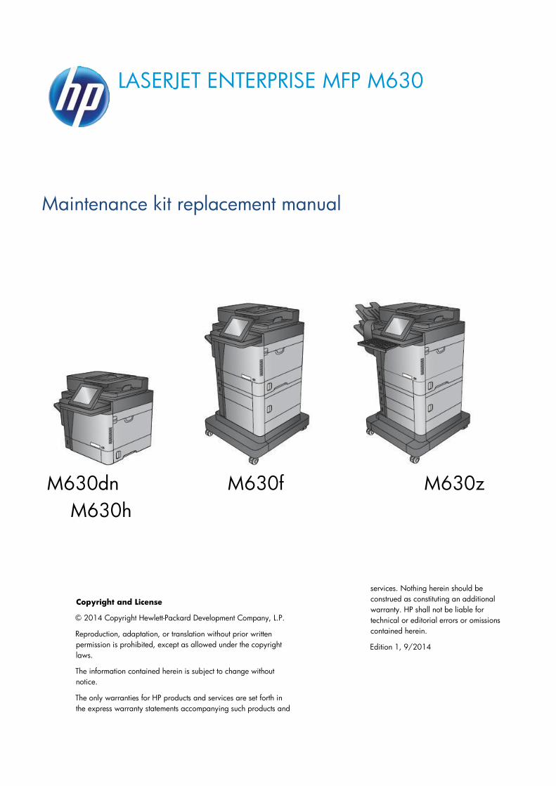
Conventions used in this guide
TIP: Helpful hints or shortcuts.
Reinstallation tip: Reinstallation helpful hints, shortcuts, or considerations.
NOTE: Information that explains a concept or how to complete a task.
IMPORTANT: Information that help the user to avoid potential printer error conditions.
CAUTION: Procedures that the user must follow to avoid losing data or damaging
the product.
WARNING! Procedures that the user must follow to avoid personal injury,
catastrophic loss of data, or extensive damage to the printer.
Page 3
Table of Contents
1. Removal and replacement ...................................................................................................................... 6
For additional service and support information ....................................................................................... 7
Removal and replacement strategy........................................................................................................ 8
Considerations during removal and replacement .............................................................................. 8
Required tools ................................................................................................................................. 10
Types of screws .............................................................................................................................. 10
Service approach ............................................................................................................................ 11
Before performing service ............................................................................................................... 11
After performing service .................................................................................................................. 11
Parts removal order ........................................................................................................................ 12
Customer self-repair (CSR) assemblies ............................................................................................... 12
Fuser-entrance guide ...................................................................................................................... 13
Fuser .............................................................................................................................................. 18
Tray 1 pickup, feed, and separation rollers...................................................................................... 26
Tray 2-5 pickup and feed rollers ...................................................................................................... 35
Transfer roller ................................................................................................................................. 41
Document-feeder maintenance kit .................................................................................................. 48
Page 4
List of Figures
Figure 1. Screwdrivers ............................................................................................................
10
Figure 2. Remove the output bin .............................................................................................. 14
Figure 3. Remove the stapling mailbox ..................................................................................... 14
Figure 4. Remove the duplex accessory ................................................................................... 15
Figure 5. Remove the fuser-entrance guide .............................................................................. 15
Figure 6. Install the fuser-entrance guide .................................................................................. 16
Figure 7. Install the duplex accessory ....................................................................................... 17
Figure 8. Install the output bin ..................................................................................................
17
Figure 9. Install the stapling mailbox .........................................................................................
18
Figure 10. Remove the output bin .............................................................................................. 19
Figure 11. Remove the stapling mailbox ..................................................................................... 20
Figure 12. Remove the duplex accessory ................................................................................... 20
Figure 13. Remove the fuser-entrance guide .............................................................................. 21
Figure 14. Remove the fuser ..................................................................................................... 21
Figure 15. Install the fuser .........................................................................................................
22
Figure 16. Install the fuser-entrance guide .................................................................................. 22
Figure 17. Install the duplex accessory ....................................................................................... 23
Figure 18. Install the output bin ..................................................................................................
23
Figure 19. Install the stapling mailbox .........................................................................................
24
Figure 20. Turn the power off..................................................................................................... 25
Figure 21. Remove the envelope feeder or the environment cover ................................................ 26
Figure 22. Open the separation roller cover ................................................................................ 26
Figure 23. Remove the separation roller ..................................................................................... 26
Figure 24. Remove one screw ................................................................................................... 27
Figure 25. Remove the bushing ................................................................................................. 27
Figure 26. Remove the roller cover ............................................................................................ 28
Figure 27. Remove the rollers ....................................................................................................
28
Figure 28. Open the separation roller cover ................................................................................ 29
Figure 29. Install the separation roller .........................................................................................
30
Figure 30. Install the rollers ....................................................................................................... 30
Figure 31. Install the roller cover ................................................................................................ 31

Page 5
Figure 32. Install the bushing .....................................................................................................
31
Figure 33. Install one screw .......................................................................................................
32
Figure 34. Install the envelope feeder or the environment cover .................................................... 32
Figure 35. Turn the power on..................................................................................................... 33
Figure 36. Turn the power off..................................................................................................... 34
Figure 37. Identify the product model ......................................................................................... 35
Figure 38. Remove the tray or trays ........................................................................................... 35
Figure 39. Locate the pickup and feed rollers .............................................................................. 36
Figure 40. Remove the rollers ....................................................................................................
36
Figure 41. Install the rollers ....................................................................................................... 37
Figure 42. Install the tray or trays. .............................................................................................. 38
Figure 43. Turn the power on..................................................................................................... 38
Figure 44. Turn the power off..................................................................................................... 40
Figure 45. Open the top cover ................................................................................................... 41
Figure 46. Remove the toner cartridge ....................................................................................... 42
Figure 47. Remove the transfer roller ......................................................................................... 42
Figure 48. Install the transfer roller ............................................................................................. 43
Figure 49. Install the toner cartridge ........................................................................................... 44
Figure 50. Turn the power on..................................................................................................... 45
Figure 51. Open the document-feeder door................................................................................. 46
Figure 52. Open the access door ............................................................................................... 47
Figure 53. Remove the document-feeder roller ............................................................................
47
Figure 54. Release one tab ....................................................................................................... 48
Figure 55. Remove the document-feeder separation pad ............................................................. 48
Figure 56. Check the spring....................................................................................................... 49
Figure 57. Position the separation pad on the product .................................................................. 50
Figure 58. Check the spring....................................................................................................... 50
Figure 59. Check the tabs ......................................................................................................... 50
Figure 60. Install the separation pad........................................................................................... 51
Figure 61. Install the document-feeder roller ............................................................................... 51
Figure 62. Rotate the roller up ................................................................................................... 52
Figure 63. Close the access door ...............................................................................................
52

Page 6
1. Removal and replacement • For additional service and support information
• Removal and replacement strategy
• Customer self-repair (CSR) assemblies
Page 7
For additional service and support information HP service personnel, go to the Link Service Access Work Bench (SAW) at
http://h41302.www4.hp.com/km/saw/home.do.
Channel partners, go to Link HP Channel Services Network (CNS) at https://h30125.www3.hp.com/hpcsn.
• Install and configure
• Product specifications
• Up to date control-panel message ( CPMD) troubleshooting
• Solutions for product issues and emerging issues
• Remove and replace part instructions and videos
• Service advisories
• Warranty & regulatory information
Page 8
Removal and replacement strategy
Considerations during removal and replacement This chapter describes the removal and replacement of field-replaceable units (FRUs) only.
Replacing FRUs is generally the reverse of removal. Notes are included to provide directions for difficult or
critical replacement procedures.
HP does not support repairing individual subassemblies or troubleshooting to the printed-circuit assembly
(PCA) component level.
WARNING! Never operate or service the product with the protective cover removed from the
laser scanner assembly. The reflected beam, although invisible, can cause damage the eyes.
The sheet-metal parts can have sharp edges. Be careful when handling sheet-metal parts.
Turn the product off, wait 5 seconds, and then remove the power cord before attempting to
service the product. If this warning is not followed, severe injury and damage to the product
can result. The power must be on for certain functional checks during troubleshooting.
However, the power cord must be disconnected during parts removal. AC voltage is still
present inside the product when the power switch is in the off position. The power cord must
be disconnected before servicing the product.
CAUTION: Some parts are sensitive to electrostatic discharge (ESD). Look for the ESD
reminder when removing product parts. Always perform service work at an ESD-protected
workstation or mat. If an ESD workstation or mat is not available, touch the sheet-metal chassis
to provide a static ground before touching an ESD-sensitive assembly.
Protect the ESD-sensitive assemblies by placing them in ESD pouches when they are out of the
product.
Do not bend or fold the flat flexible cables (FFCs) during removal or installation.
Incorrectly routed or loose wire harnesses might interfere with other internal components or
assemblies and be damaged, pinched, or frayed. Make sure that wire harnesses are correctly
routed and retained when installing assemblies.
Do not expose the toner cartridge (or toner cartridges), to strong light even for a short time.
IMPORTANT: When an assembly is removed that includes a rating plate or tag (or a
product code label), make sure to transfer the plate or tag (or code label) to the replacement
assembly.
NOTE: To install a self-tapping screw, first turn it counterclockwise to align it with the existing
thread pattern, and then carefully turn it clockwise to tighten. Do not overtighten. If a
selftapping screw-hole becomes stripped, repair the screw-hole or replace the affected
assembly.
Always take note of the length, diameter, color, type, and location of each removed screw.
Make sure that screws are installed in the original location they were removed from during
reinstallation.

Page 9
During assembly removal and replacement, or if the product is moved, remove the toner
cartridge or cartridges.
Page 10
Toner is a non-poisonous substance composed of plastic and a small number of colored
components. If toner gets on the skin or clothing, wipe it off with dry tissue paper and wash in
cold water. Hot water sets toner and it might be difficult, or impossible, to remove. Toner
easily breaks down vinyl materials—avoid letting toner contact with vinyl.
During assembly removal and replacement, or if the product is moved, remove the tray
cassette or cassettes.
TIP: For clarity, some figures in this chapter show assemblies removed that are not required to
be removed to service the product (for example, the scanner and document feeder
assemblies). The procedures in this manual are correct for this product
Required tools • #2 Phillips screwdriver with a magnetic tip and a 152-mm (6-in) shaft length
NOTE: For the best fit, use a JIS #2 Phillips screwdriver for the stapler/stacker.
• Small, flat-blade screwdriver
• Needle-nose pliers
• ESD strap (if one is available)
Types of screws
WARNING! Make sure that assemblies are replaced with the correct screw type. Using the
incorrect screw (for example, substituting a long screw for the correct shorter screw) can
cause damage to the product or interfere with product operation. Do not intermix screws that
are removed from one assembly with the screws that are removed from another assembly.
Penlight
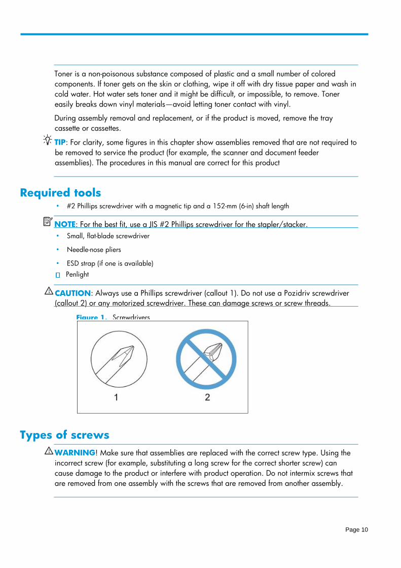
CAUTION : Always use a Phillips screwdriver (callout 1) . Do not use a Pozidriv screwdriver
( callout 2) or any motorized screwdriver. These can damage screws or screw threads.
Figure 1. Screwdrivers
Page 11
Service approach The product uses a field repair strategy. Defective parts are diagnosed and replaced at the Field
Replaceable Unit (FRU) assembly level. Repair normally begins by using the product internal diagnostics
and the following two-step process:
1. Isolate the problem to the major system (for example, the network or server, or the product).
2. Troubleshoot the problem by using the procedures in the troubleshooting chapter.
After locating a faulty part, the product can usually be repaired at the assembly level by replacing FRUs.
Some mechanical assemblies might need to be repaired at the subassembly level. Hewlett-Packard
Company does not support replacement of components on the printed circuit assembles.
The user replaces toner cartridges as they are depleted. Additional instructions about other
userreplaceable parts are provided in this section.
The product tracks the amount of use on the customer-replaceable supplies by keeping a page count. The
product prompts the user to replace certain items when a supply is depleted or a specific number of pages
has been printed.
Swapping toner cartridges between products might cause a misrepresentation of supply life values and is
not recommended.
Before performing service
WARNING! Turn the product off, wait 30 seconds, and then remove the power cord before
attempting to service the product. If this warning is not followed, severe injury and damage to
the product can result. The power must be on for certain functional checks during
troubleshooting. However, the power supply should be disconnected during parts removal.
1. Remove all paper.
2. Place the product on an ESD mat (if available). If an ESD workstation or mat is not available, touching
the sheet-metal chassis to provide a static ground before touching an ESD-sensitive assembly.
3. Remove the toner cartridge or toner cartridges.
4. Remove the trays.
After performing service 1. Reinstall the toner cartridge or toner cartridges.
2. Reinstall the trays.
3. Return all paper to the trays.
4. Plug in the power cable and turn on the product.
5. Perform print-quality tests by printing from a host computer, the scanner glass, and the document
feeder.
6. Reset the Maintenance kit counter:

Page 12
a At the product control panel, press the Home button.
b Open the following menus:
i Administration
ii Manage Supplies
iii Reset Supplies
iv New Maintenance Kit
c 3. Select the Yes option to reset the maintenance-kit counter
Parts removal order If needed, a list at the beginning of a removal procedure lists all of the assemblies that must be removed to
reach the target assembly. Use these lists to determine which parts must be removed before removing
other parts.
For procedures and/or steps that require identifying the right, left, or rear side of the product, face the
front of the product for correct orientation.
Customer self-repair (CSR) assemblies • Fuser-entrance guide
• Fuser
• Tray 1 pickup, feed, and separation rollers
• Tray 2-5 pickup and feed rollers
• Transfer roller
• Document-feeder maintenance kit
Page 13
Fuser-entrance guide • Introduction
• Step 1: Remove the output bin and bin base assembly or stapling mailbox
• Step 2: Remove the duplex accessory
• Step 3: Remove the fuser-entrance guide
• Step 4: Unpack the replacement fuser-entrance guide
• Step 5: Install the fuser-entrance guide
• Step 6: Install the duplex accessory
• Step 7: Install the output bin and bin base assembly or stapling mailbox
• Step 8: Turn the product power on
• Parts Return
Introduction This document provides the procedures to remove and replace the fuser-entrance guide.
Before servicing
Use the table below to identify the correct kit part number for your product, and then go to
www.hp.com/buy/parts to order the kit
Fuser-entrance guide kit part numbers
B3G84-67904 Fuser-entrance guide kit with instruction guide
Do the following steps:
a. Turn off the product.
b. Disconnect the power cable.
WARNING! To avoid damage to the product, turn the product off, wait 30 seconds, and
then remove the power cord before attempting to service the product.
Required tools
No special tools are required to install this kit.
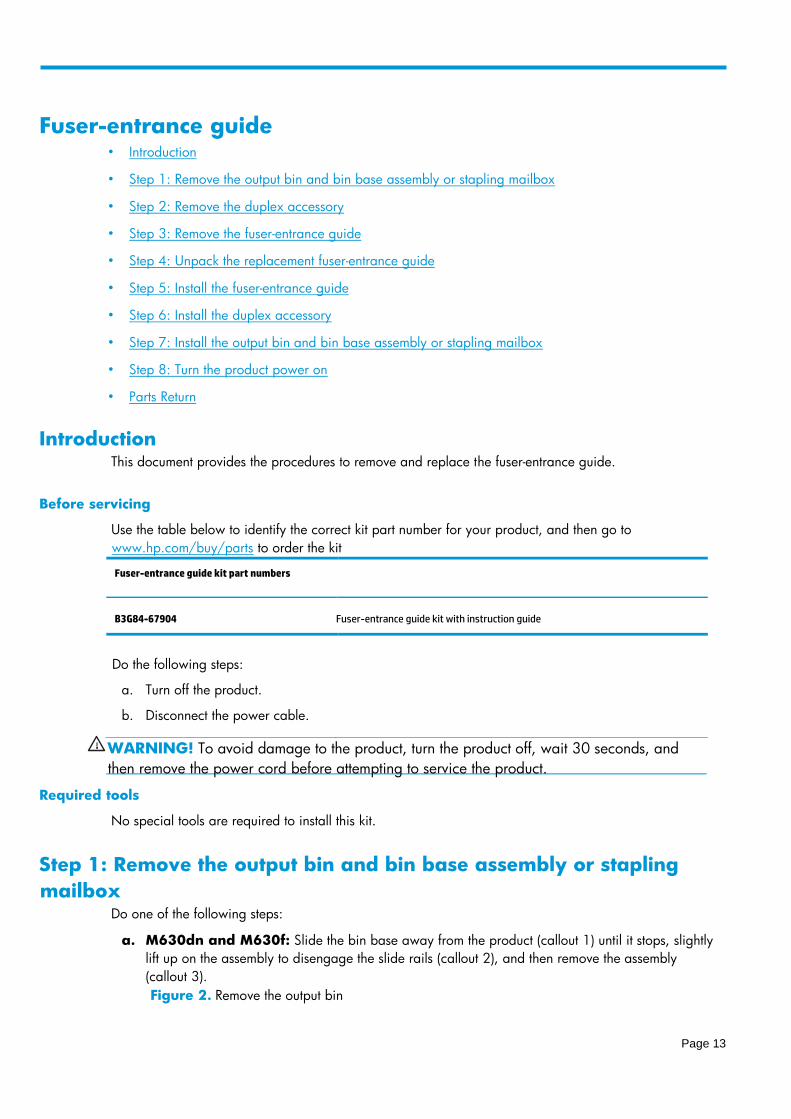
Step 1: Remove the output bin and bin base assembly or stapling
mailbox Do one of the following steps:
a. M630dn and M630f: Slide the bin base away from the product (callout 1) until it stops, slightly
lift up on the assembly to disengage the slide rails (callout 2), and then remove the assembly
(callout 3).
Figure 2. Remove the output bin
Page 14
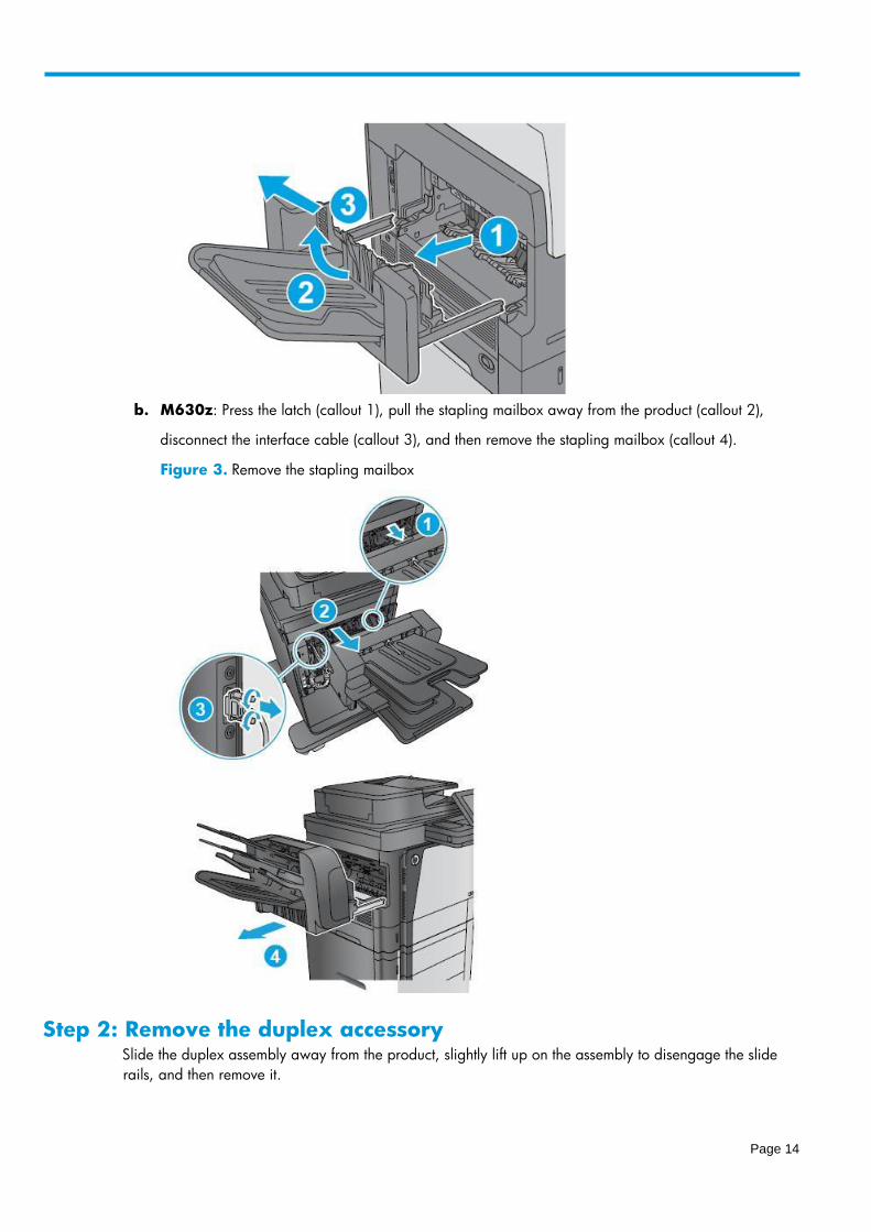
b. M630z: Press the latch (callout 1), pull the stapling mailbox away from the product (callout 2),
disconnect the interface cable (callout 3), and then remove the stapling mailbox (callout 4).
Figure 3. Remove the stapling mailbox
Step 2: Remove the duplex accessory Slide the duplex assembly away from the product, slightly lift up on the assembly to disengage the slide
rails, and then remove it.

Page 15
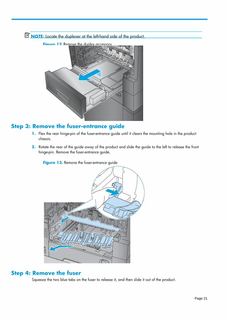
NOTE: Locate the duplexer at the left-hand side of the product.
Figure 4. Remove the duplex accessory
Step 3: Remove the fuser-entrance guide
1. Flex the rear hinge-pin of the fuser-entrance guide until it clears the mounting hole in the product
chassis.
2. Rotate the rear of the guide away of the product and slide the guide to the left to release the front
hinge-pin. Remove the fuser-entrance guide.
Figure 5. Remove the fuser-entrance guide
Step 4: Unpack the replacement fuser-entrance guide Unpack the replacement assembly from the packaging.
Page 16
Product return and recycling.
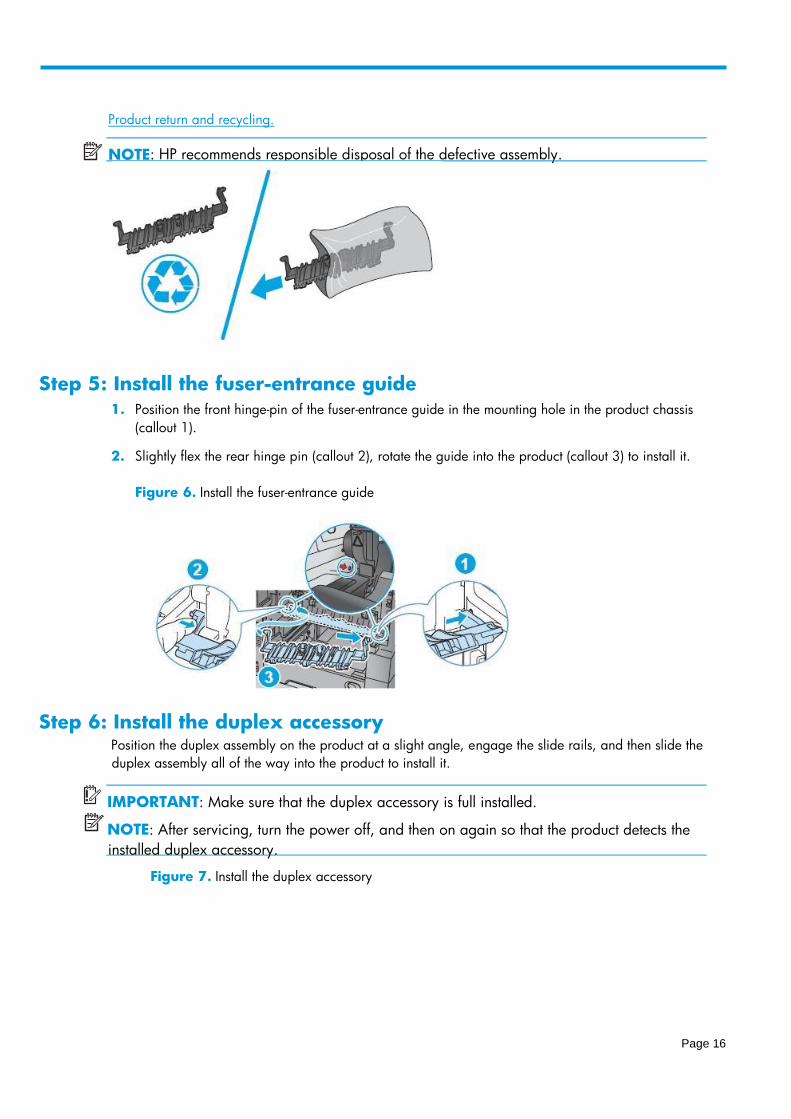
Step 5: Install the fuser-entrance guide
1. Position the front hinge-pin of the fuser-entrance guide in the mounting hole in the product chassis
(callout 1).
2. Slightly flex the rear hinge pin (callout 2), rotate the guide into the product (callout 3) to install it.
Figure 6. Install the fuser-entrance guide
Step 6: Install the duplex accessory Position the duplex assembly on the product at a slight angle, engage the slide rails, and then slide the
duplex assembly all of the way into the product to install it.
IMPORTANT: Make sure that the duplex accessory is full installed.
NOTE: After servicing, turn the power off, and then on again so that the product detects the
installed duplex accessory.
Figure 7. Install the duplex accessory
NOTE : HP recommends responsible disposal of the def ective assembly.
Page 17
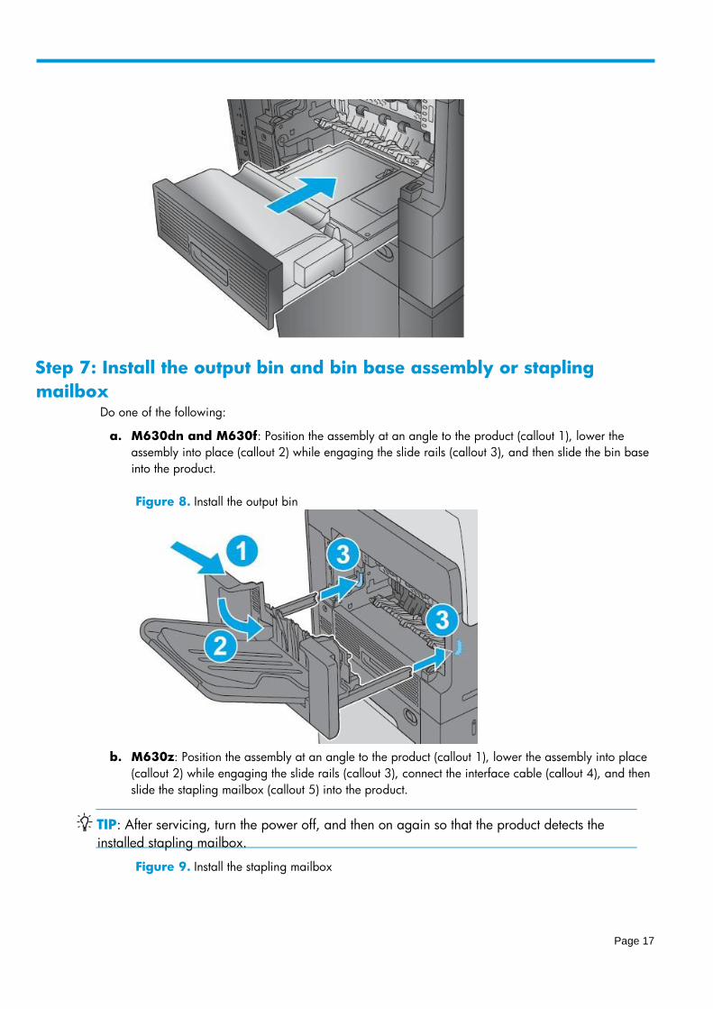
Step 7: Install the output bin and bin base assembly or stapling
mailbox Do one of the following:
a. M630dn and M630f: Position the assembly at an angle to the product (callout 1), lower the
assembly into place (callout 2) while engaging the slide rails (callout 3), and then slide the bin base
into the product.
Figure 8. Install the output bin
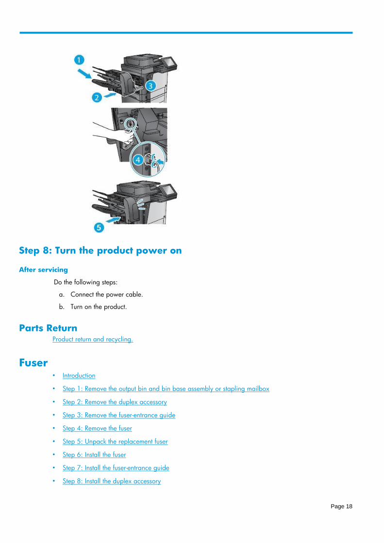
b. M630z: Position the assembly at an angle to the product (callout 1), lower the assembly into place
(callout 2) while engaging the slide rails (callout 3), connect the interface cable (callout 4), and then
slide the stapling mailbox (callout 5) into the product.
TIP: After servicing, turn the power off, and then on again so that the product detects the
installed stapling mailbox.
Figure 9. Install the stapling mailbox
Page 18
Step 8: Turn the product power on
After servicing
Do the following steps:
a. Connect the power cable.
b. Turn on the product.
Parts Return
Product return and recycling.
Fuser • Introduction
• Step 1: Remove the output bin and bin base assembly or stapling mailbox
• Step 2: Remove the duplex accessory
• Step 3: Remove the fuser-entrance guide
• Step 4: Remove the fuser
• Step 5: Unpack the replacement fuser
• Step 6: Install the fuser
• Step 7: Install the fuser-entrance guide
• Step 8: Install the duplex accessory

Page 19
• Step 9: Install the output bin and bin base assembly or stapling mailbox
• Step 10: Turn the product power on
• Step 11: Reset the supplies counter
• Parts Return
Introduction This document provides the procedures to remove and replace the fuser.
Before servicing
Use the table below to identify the correct kit part number for your product, and then go to
www.hp.com/buy/parts to order the kit.
Fuser kit part numbers
B3M77-67903 Fuser (110V) kit with instruction guide
B3M78-67903 Fuser (220V) kit with instruction guide
Do the following steps:
a. Turn off the product.
b. Disconnect the power cable.
WARNING! To avoid damage to the product, turn the product off, wait 30 seconds, and
then remove the power cord before attempting to service the product.
Required tools
No special tools are required to install this kit.
Step 1: Remove the output bin and bin base assembly or stapling
mailbox Do one of the following steps:
a. M630dn and M630f: Slide the bin base away from the product (callout 1) until it stops, slightly
lift up on the assembly to disengage the slide rails (callout 2), and then remove the assembly
(callout 3).
Figure 10. Remove the output bin
Page 20
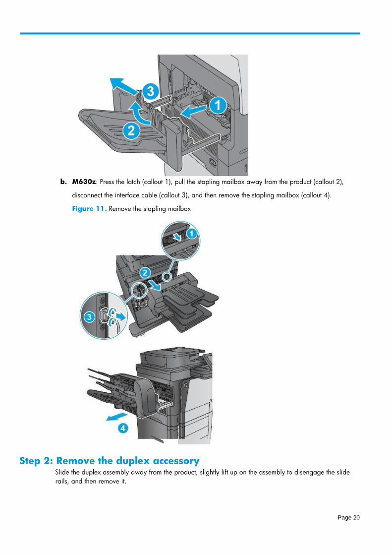
b. M630z: Press the latch (callout 1), pull the stapling mailbox away from the product (callout 2),
disconnect the interface cable (callout 3), and then remove the stapling mailbox (callout 4).
Figure 11. Remove the stapling mailbox
Step 2: Remove the duplex accessory Slide the duplex assembly away from the product, slightly lift up on the assembly to disengage the slide
rails, and then remove it.
Page 21
Step 3: Remove the fuser-entrance guide
1. Flex the rear hinge-pin of the fuser-entrance guide until it clears the mounting hole in the product
chassis.
2. Rotate the rear of the guide away of the product and slide the guide to the left to release the front
hinge-pin. Remove the fuser-entrance guide.
Figure 13. Remove the fuser-entrance guide
Step 4: Remove the fuser Squeeze the two blue tabs on the fuser to release it, and then slide it out of the product.
NOTE Locate the duplexer at the l : eft - hand side of the product.
Figure 12. Remove the duplex accessory

Page 22
Step 5: Unpack the replacement fuser Unpack the replacement assembly from the packaging.
Products return and recycling.
Step 6: Install the fuser Position the fuser in the product, push in to install it, and then make sure that it is fully seated.
CAUTION : The fuser is very hot. After turning the product power off, allow the fuser to cool
for at least 30 minutes before removing it.
Figure 14. Remove the fuser
NOTE : HP recommends responsible disposal of the defective assembly.
Page 23
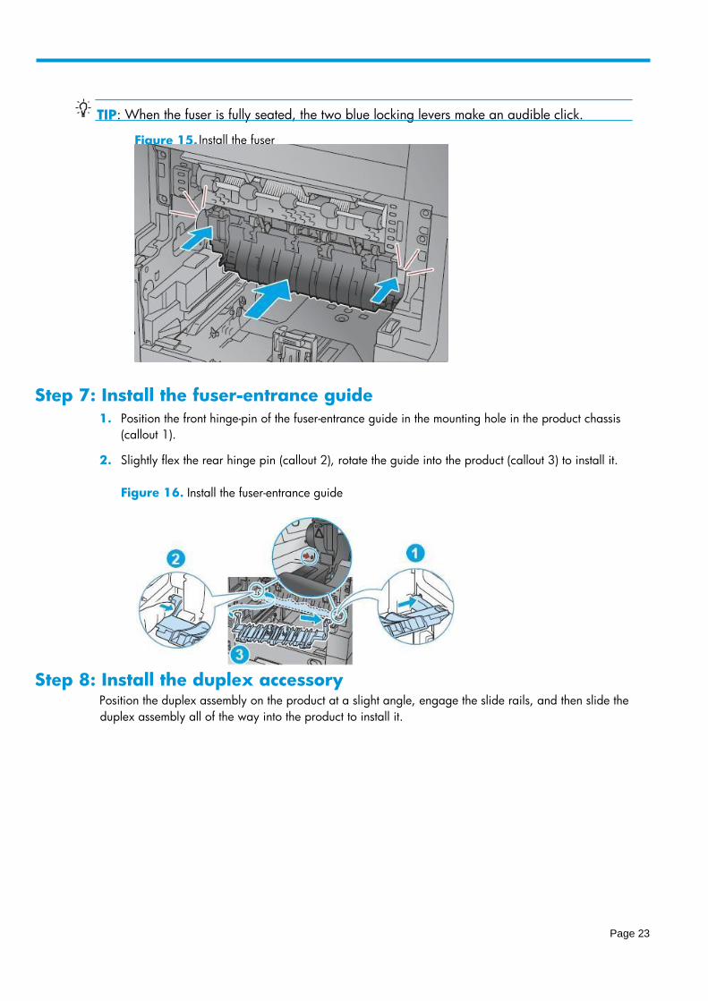
Step 7: Install the fuser-entrance guide
1. Position the front hinge-pin of the fuser-entrance guide in the mounting hole in the product chassis
(callout 1).
2. Slightly flex the rear hinge pin (callout 2), rotate the guide into the product (callout 3) to install it.
Figure 16. Install the fuser-entrance guide
Step 8: Install the duplex accessory Position the duplex assembly on the product at a slight angle, engage the slide rails, and then slide the
duplex assembly all of the way into the product to install it.
TIP : When the fuser is fully seated, the two blue locking levers make an audible click.
Figure 15. Install the fuser
Page 24
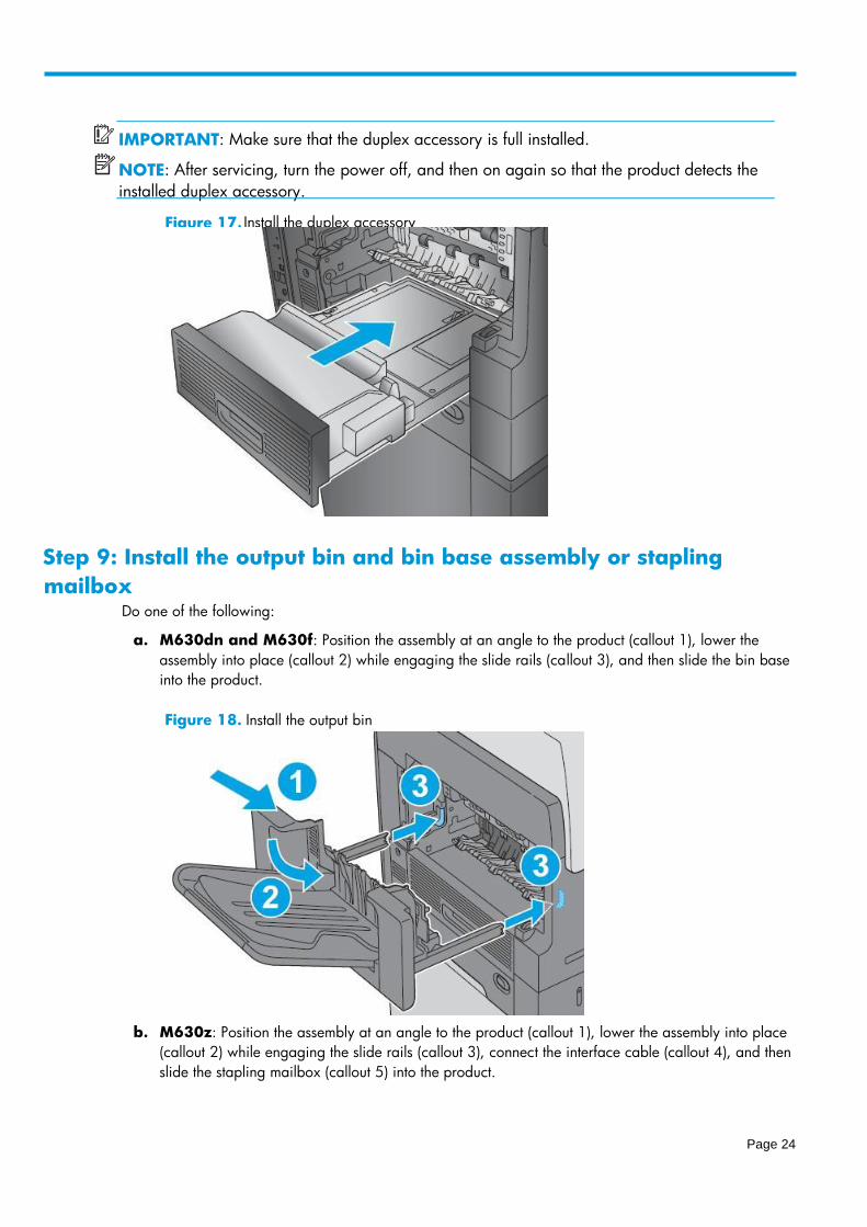
Step 9: Install the output bin and bin base assembly or stapling
mailbox Do one of the following:
a. M630dn and M630f: Position the assembly at an angle to the product (callout 1), lower the
assembly into place (callout 2) while engaging the slide rails (callout 3), and then slide the bin base
into the product.
Figure 18. Install the output bin
b. M630z: Position the assembly at an angle to the product (callout 1), lower the assembly into place
(callout 2) while engaging the slide rails (callout 3), connect the interface cable (callout 4), and then
slide the stapling mailbox (callout 5) into the product.
IMPORTANT Make sure that the duplex accessory is full installed. :
NOTE After servicing, turn the : power off, and then on again so that the product detects the
installed duplex accessory.
Figure 17. Install the duplex accessory
Page 25
Step 10: Turn the product power on
After servicing
Do the following steps:
a. Connect the power cable.
b. Turn on the product.
Step 11: Reset the supplies counter
1. From the Home screen on the control panel, scroll to and touch the Administration button.
2. Open the following menus:
– Manage Supplies
– Reset Supplies
– New Maintenance Kit
3. Select the Reset item to reset the supplies counter.
Parts Return
Products return and recycling.
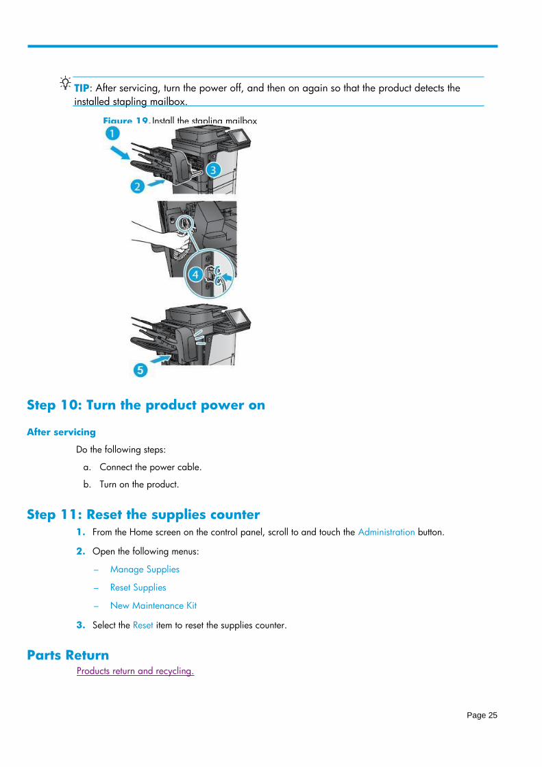
TIP After servicing, turn the power off, : and then on again so that the product detects the
installed stapling mailbox.
Figure 19. Install the stapling mailbox
Page 26
Tray 1 pickup, feed, and separation rollers • Introduction
• Step 1: Remove the Tray 1 pickup, feed, and separation rollers
• Step 2: Unpack the replacement rollers
• Step 3: Install the Tray 1 pickup, feed, and separation rollers
• Parts Return
Introduction This document provides the procedures to remove and replace the Tray 1 pickup, feed, and separation
rollers.
Before servicing
Use the table below to identify the correct kit part number for your product, and then go to
www.hp.com/buy/parts to order the kit.
Required tools
#2 Phillips screwdriver with a magnetic tip
Step 1: Remove the Tray 1 pickup, feed, and separation rollers
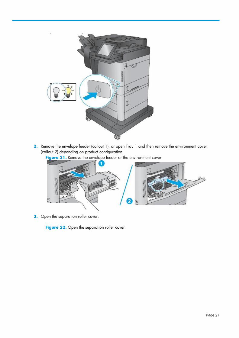
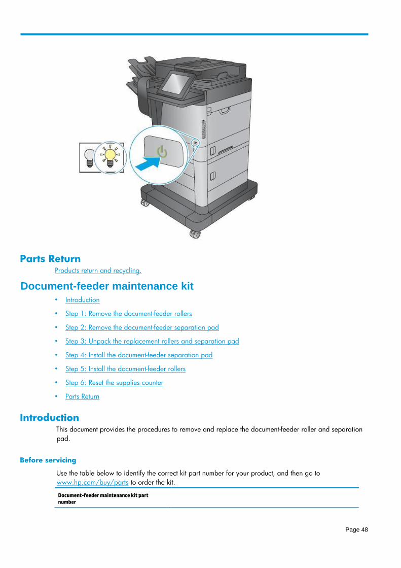
1. Use the power switch to turn the product power off.
Figure 20. Turn the power off
Tray 1 pickup, feed, and separation rollers kit part number
B3G84 - 67906 Tray 1 pickup, feed, and separation rollers with instruction guide
Page 27
2. Remove the envelope feeder (callout 1), or open Tray 1 and then remove the environment cover
(callout 2) depending on product configuration.
Figure 21. Remove the envelope feeder or the environment cover
3. Open the separation roller cover.
Figure 22. Open the separation roller cover
Page 28
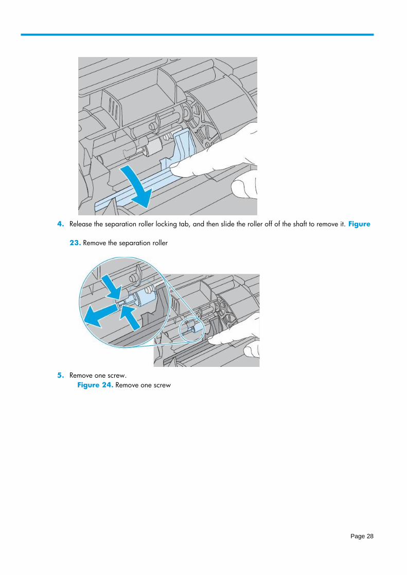
4. Release the separation roller locking tab, and then slide the roller off of the shaft to remove it. Figure
23. Remove the separation roller
5. Remove one screw.
Figure 24. Remove one screw

Page 29
6. Slide the bushing off of the shaft. Figure 25. Remove the bushing
7. Remove the roller cover.
Figure 26. Remove the roller cover

Page 30
8. Remove the pickup and feed rollers.
Figure 27. Remove the rollers
Step 2: Unpack the replacement rollers Unpack the replacement assemblies from the packaging.
CAUTION: Avoid touching the surface of the replacement rollers. Skin oils on the rollers can
cause print quality problems. Thoroughly wash your hands with soap and water to remove
skin oils, and then completely dry them.
Product return and recycling
Page 31
Step 3: Install the Tray 1 pickup, feed, and separation rollers
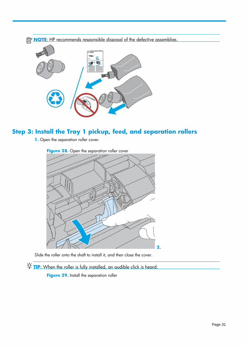
1. Open the separation roller cover.
Figure 28. Open the separation roller cover
2.
Slide the roller onto the shaft to install it, and then close the cover.
TIP: When the roller is fully installed, an audible click is heard.
Figure 29. Install the separation roller
NOTE : HP recommends responsible disposal of the defective assemblies.

Page 32
4. Install the roller cover.
Figure 31. Install the roller cover
3. Install the pickup and feed rollers.
TIP Install the roller with the white gear on the lower shaft. :
Figure 30. Install the rollers
Page 33
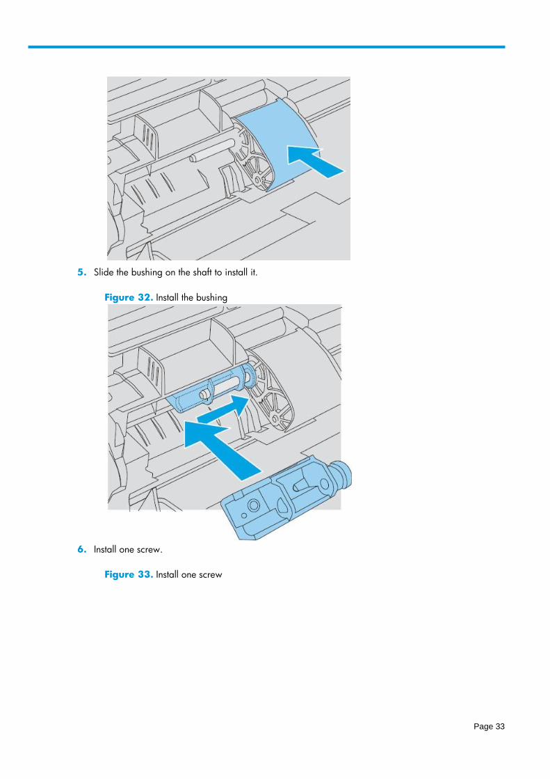
5. Slide the bushing on the shaft to install it.
Figure 32. Install the bushing
6. Install one screw.
Figure 33. Install one screw
Page 34
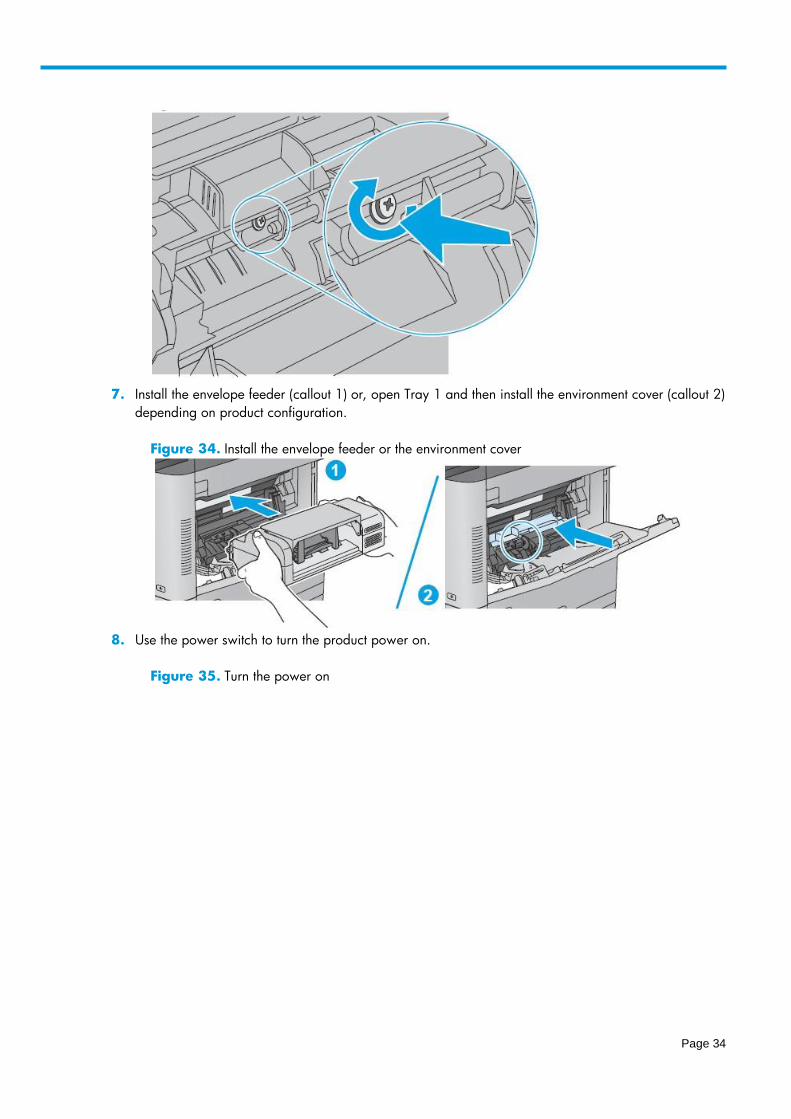
7. Install the envelope feeder (callout 1) or, open Tray 1 and then install the environment cover (callout 2)
depending on product configuration.
Figure 34. Install the envelope feeder or the environment cover
8. Use the power switch to turn the product power on.
Figure 35. Turn the power on

Page 35
Parts Return
Products return and recycling.
Tray 2-5 pickup and feed rollers • Introduction
• Step 1: Remove the Tray 2 - 5 pickup and feed rollers
• Step 2: Unpack the replacement rollers
• Step 3: Install the Tray 2 - 5 pickup and feed rollers
• Parts Return
Introduction This document provides the procedures to remove and replace the Tray 2 - X pickup and feed rollers.
Before servicing
Use the table below to identify the correct kit part number for your product, and then go to
www.hp.com/buy/parts to order the kit.
Required tools
No special tools are required to install this kit.
Tray 2 - X pickup and feed rollers kit part number
B3G84 - 6790 5 Tray 2 - X pickup and rollers kit with instruction guide
Page 36
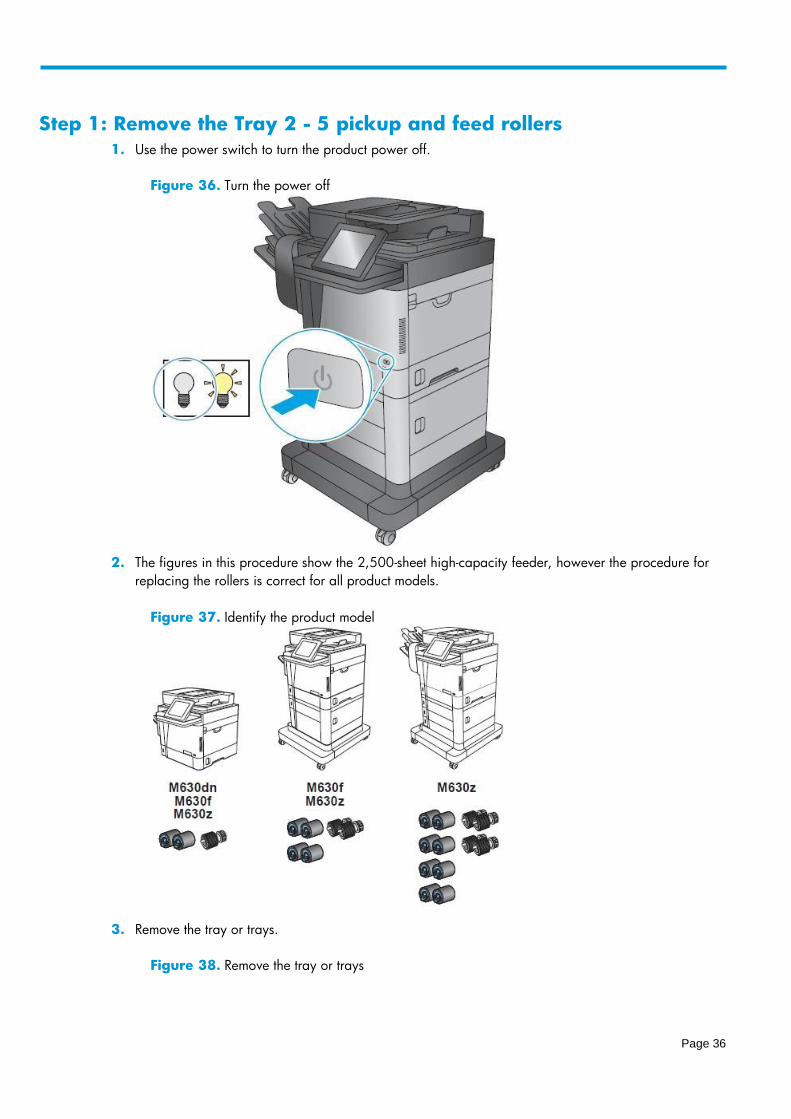
Step 1: Remove the Tray 2 - 5 pickup and feed rollers
1. Use the power switch to turn the product power off.
Figure 36. Turn the power off
2. The figures in this procedure show the 2,500-sheet high-capacity feeder, however the procedure for
replacing the rollers is correct for all product models.
Figure 37. Identify the product model
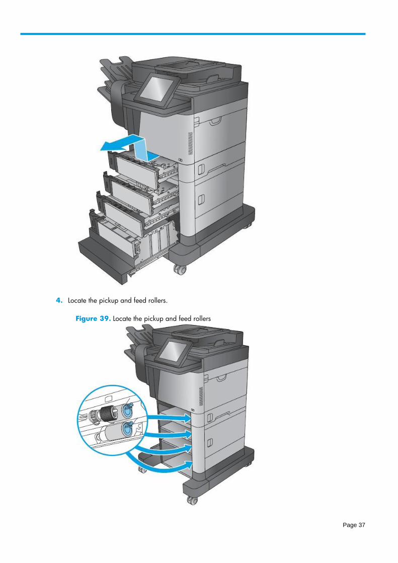
3. Remove the tray or trays.
Figure 38. Remove the tray or trays
Page 37
4. Locate the pickup and feed rollers.
Figure 39. Locate the pickup and feed rollers
Page 38
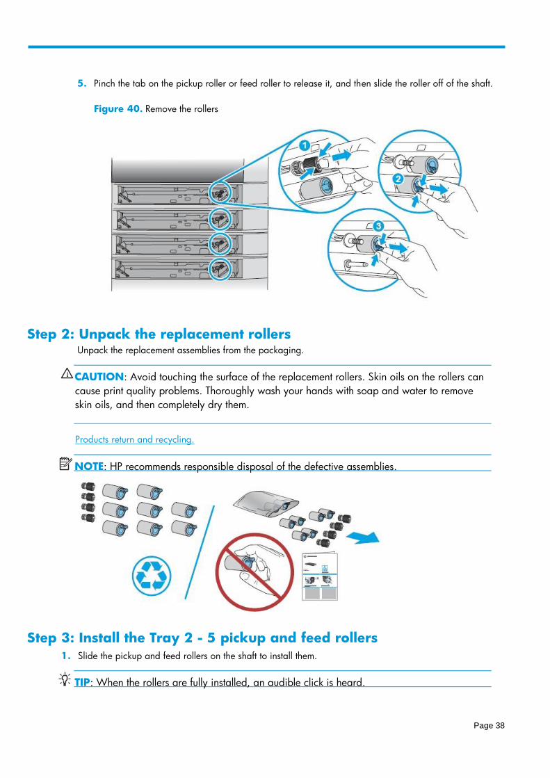
5. Pinch the tab on the pickup roller or feed roller to release it, and then slide the roller off of the shaft.
Figure 40. Remove the rollers
Step 2: Unpack the replacement rollers Unpack the replacement assemblies from the packaging.
CAUTION: Avoid touching the surface of the replacement rollers. Skin oils on the rollers can
cause print quality problems. Thoroughly wash your hands with soap and water to remove
skin oils, and then completely dry them.
Products return and recycling.
NOTE: HP recommends responsible disposal of the defective assemblies.
Step 3: Install the Tray 2 - 5 pickup and feed rollers
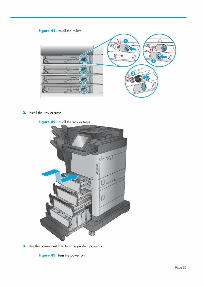
1. Slide the pickup and feed rollers on the shaft to install them.
TIP: When the rollers are fully installed, an audible click is heard.
Page 39
Figure 41. Install the rollers
2. Install the tray or trays.
Figure 42. Install the tray or trays.
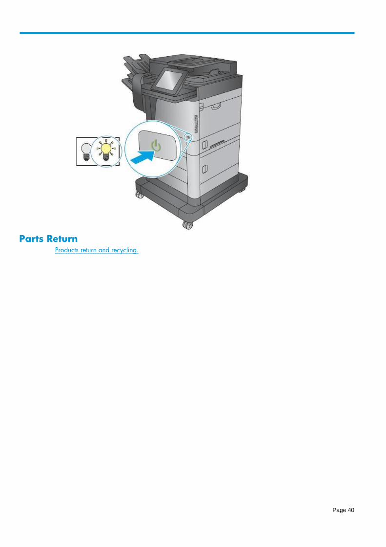
3. Use the power switch to turn the product power on.
Figure 43. Turn the power on
Page 40
Parts Return
Products return and recycling.
Page 41
Transfer roller • Introduction
• Step 1: Remove the transfer roller
• Step 2: Unpack the replacement roller
• Step 3: Install the transfer roller
• Parts Return
Introduction This document provides the procedures to remove and replace the transfer roller.
Before servicing
Use the table below to identify the correct kit part number for your product, and then go to
www.hp.com/buy/parts to order the kit.
Transfer roller kit part number
B3G84-67901 Transfer roller with instruction guide
Required tools
A special removal tool, and a pair of protective gloves are provided in this kit.
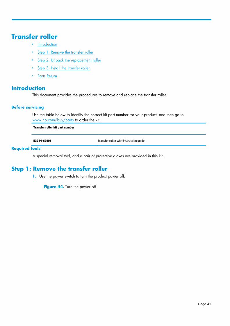
Step 1: Remove the transfer roller
1. Use the power switch to turn the product power off.
Figure 44. Turn the power off
Page 42
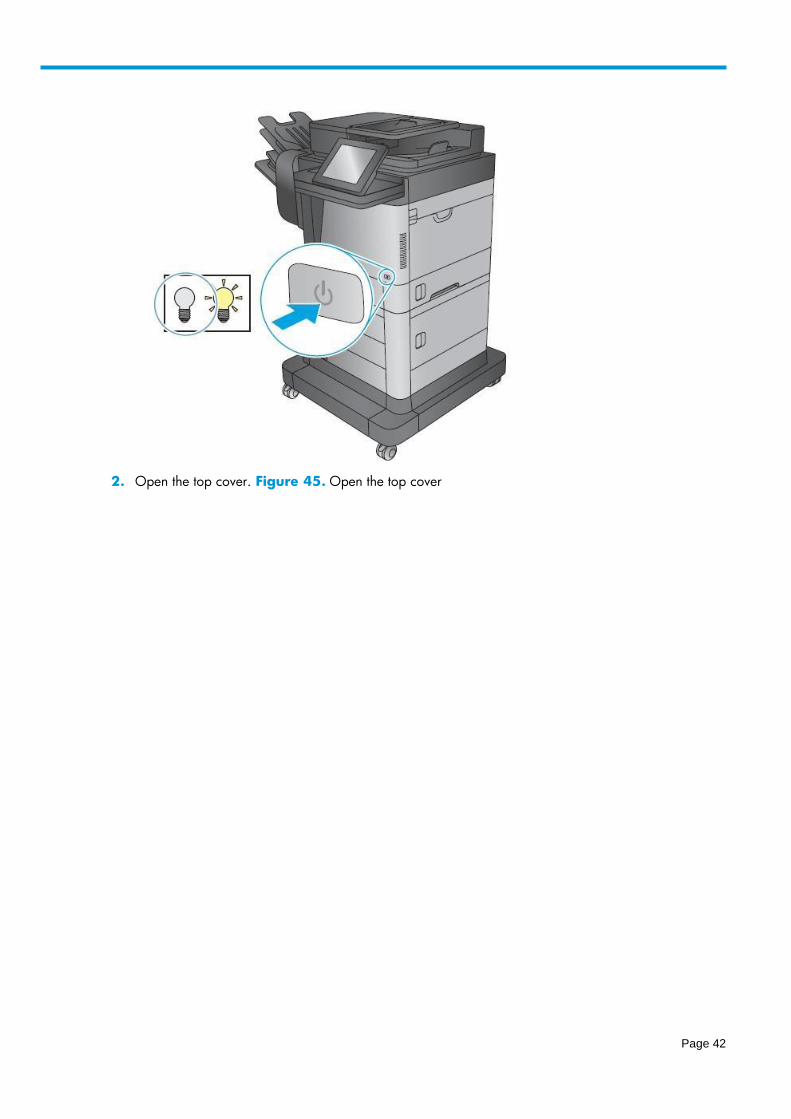
2. Open the top cover. Figure 45. Open the top cover

Page 43
3. Remove the toner cartridge.
Figure 46. Remove the toner cartridge
Page 44
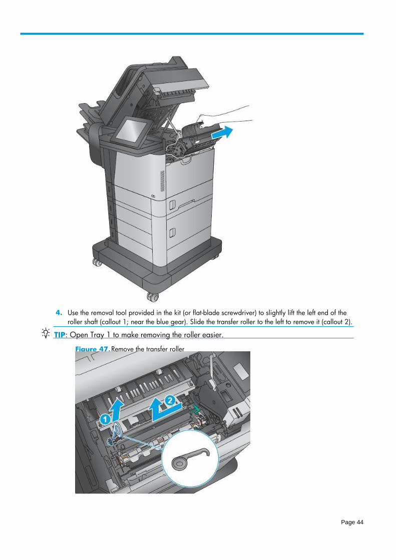
4. Use the removal tool provided in the kit (or flat-blade screwdriver) to slightly lift the left end of the
roller shaft (callout 1; near the blue gear). Slide the transfer roller to the left to remove it (callout 2).
TIP : Open Tray 1 to make removing the roller easier.
Figure 47. Remove the transfer roller
Page 45
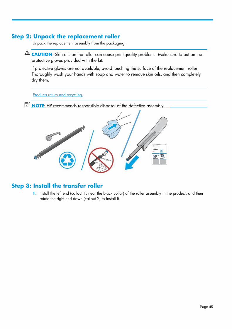
Step 2: Unpack the replacement roller Unpack the replacement assembly from the packaging.
CAUTION: Skin oils on the roller can cause print-quality problems. Make sure to put on the
protective gloves provided with the kit.
If protective gloves are not available, avoid touching the surface of the replacement roller.
Thoroughly wash your hands with soap and water to remove skin oils, and then completely
dry them.
Step 3: Install the transfer roller
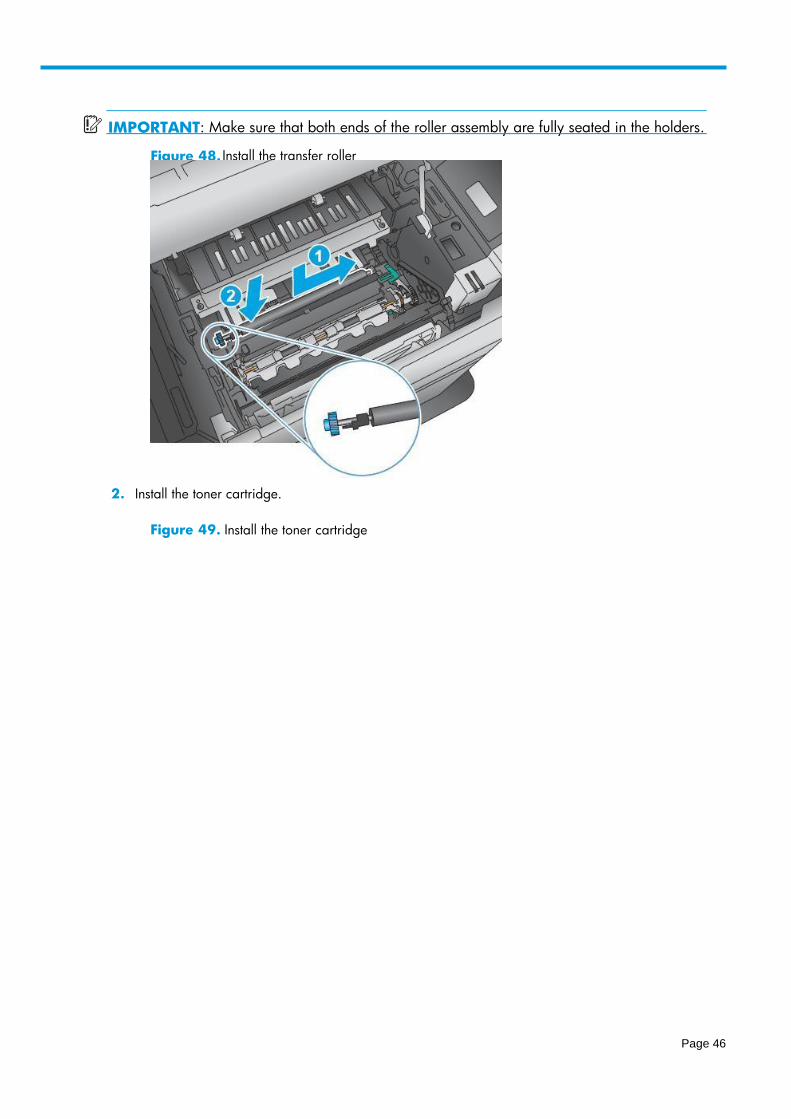
1. Install the left end (callout 1; near the black collar) of the roller assembly in the product, and then
rotate the right end down (callout 2) to install it.
Products return and recycling .
NOTE : HP recommends responsible disposal of the defective assembly.
Page 46
2. Install the toner cartridge.
Figure 49. Install the toner cartridge
IMPORTANT : Make sure that both ends of the roller assembly are fully seated in the holders.
Figure 48. Instal l the transfer roller
Page 47
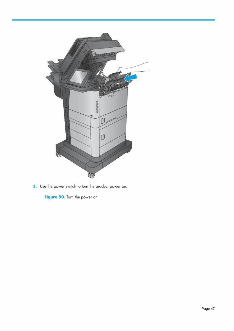
3. Use the power switch to turn the product power on.
Figure 50. Turn the power on
Page 48
Parts Return Products return and recycling.
Document-feeder maintenance kit • Introduction
• Step 1: Remove the document-feeder rollers
• Step 2: Remove the document-feeder separation pad
• Step 3: Unpack the replacement rollers and separation pad
• Step 4: Install the document-feeder separation pad
• Step 5: Install the document-feeder rollers
• Step 6: Reset the supplies counter
• Parts Return
Introduction This document provides the procedures to remove and replace the document-feeder roller and separation
pad.
Before servicing
Use the table below to identify the correct kit part number for your product, and then go to
www.hp.com/buy/parts to order the kit.
Document-feeder maintenance kit part number
Page 49
L2725-60002 Document-feeder maintenance kit with instruction guide
NOTE: The document-feeder maintenance kit includes the pickup and feed rollers assembly and the separation pad assembly.
Required tools
No special tools are required to install this kit.
IMPORTANT: When a replacement roller is installed, reset the New Document Feeder Kit
supplies counter. See Step 6: Reset the supplies counter on page 52.
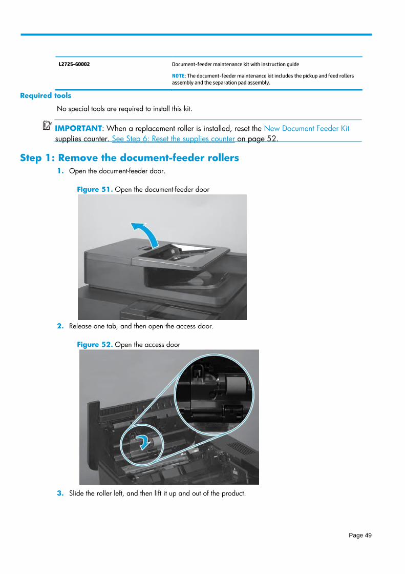
Step 1: Remove the document-feeder rollers
1. Open the document-feeder door.
Figure 51. Open the document-feeder door
2. Release one tab, and then open the access door.
Figure 52. Open the access door
3. Slide the roller left, and then lift it up and out of the product.

Page 50
Step 2: Remove the document-feeder separation pad
1. Release one tab.
Figure 54. Release one tab
2. Rotate the separation pad and holder up (callout 1), and then lift it up (callout 2) to remove it.
NOTE If the roller does not drop down when the access door is opened, rotate it down now. :
Figure 53. Remove the document - feeder roller
Page 51
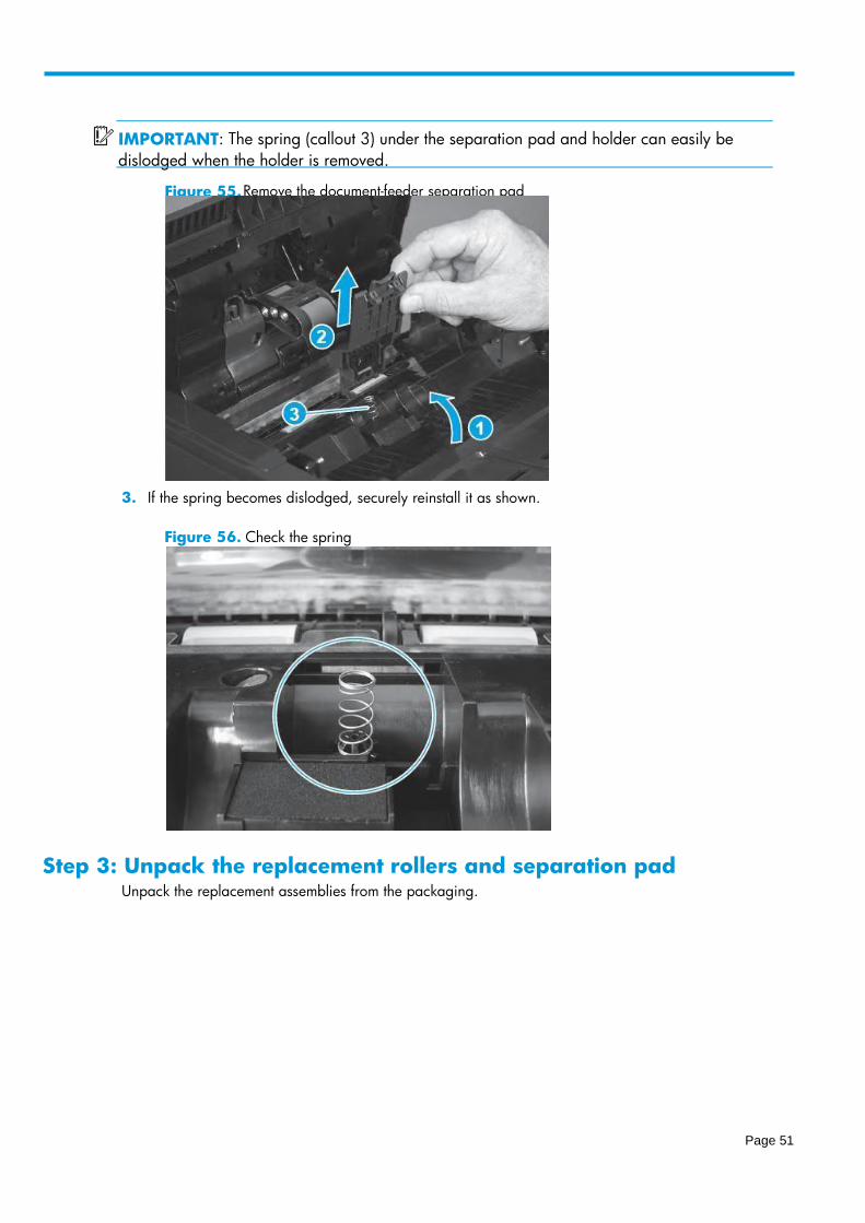
3. If the spring becomes dislodged, securely reinstall it as shown.
Figure 56. Check the spring
Step 3: Unpack the replacement rollers and separation pad Unpack the replacement assemblies from the packaging.
IMPORTANT : The spring (callout 3) under the separation pad and holder can easily be
dislodged when the holder is removed.
Figure 55. Remove the document - feeder separation pad
Page 52
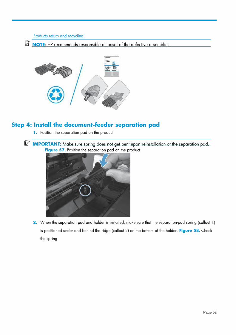
Step 4: Install the document-feeder separation pad
1. Position the separation pad on the product.
IMPORTANT: Make sure spring does not get bent upon reinstallation of the separation pad.
Figure 57. Position the separation pad on the product
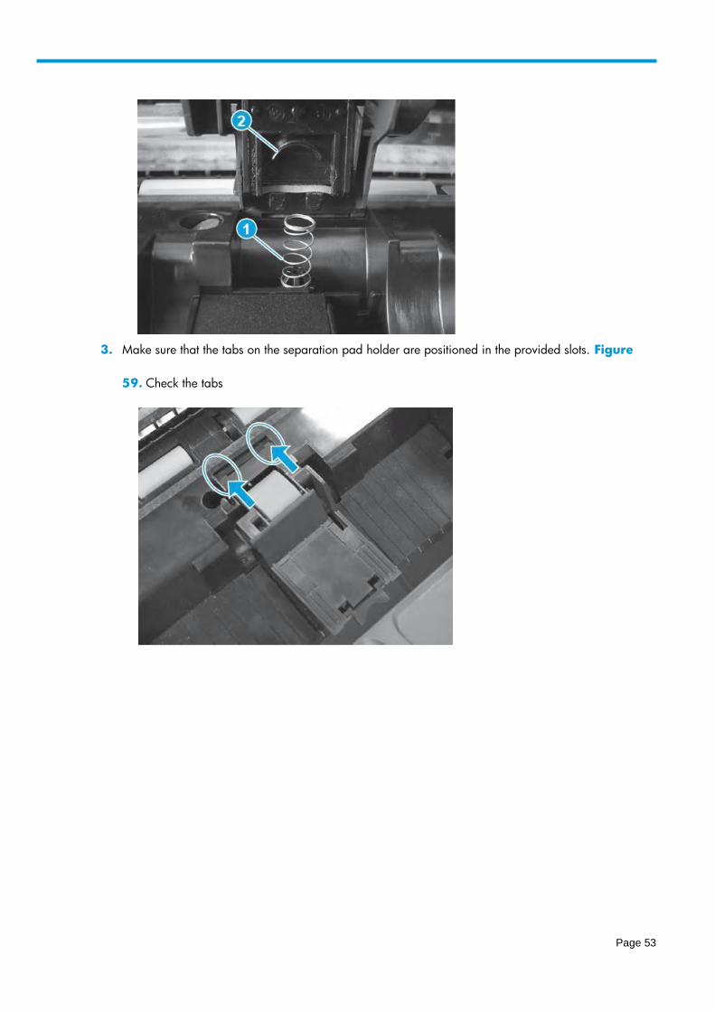
2. When the separation pad and holder is installed, make sure that the separation-pad spring (callout 1)
is positioned under and behind the ridge (callout 2) on the bottom of the holder. Figure 58. Check
the spring
Products return and recycling .
NOTE : HP recommends responsible disposal of the defective assemblies.
Page 53
3. Make sure that the tabs on the separation pad holder are positioned in the provided slots. Figure
59. Check the tabs
Page 54
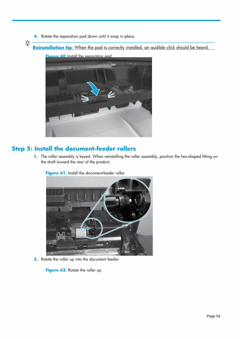
Step 5: Install the document-feeder rollers
1. The roller assembly is keyed. When reinstalling the roller assembly, position the hex-shaped fitting on
the shaft toward the rear of the product.
Figure 61. Install the document-feeder roller
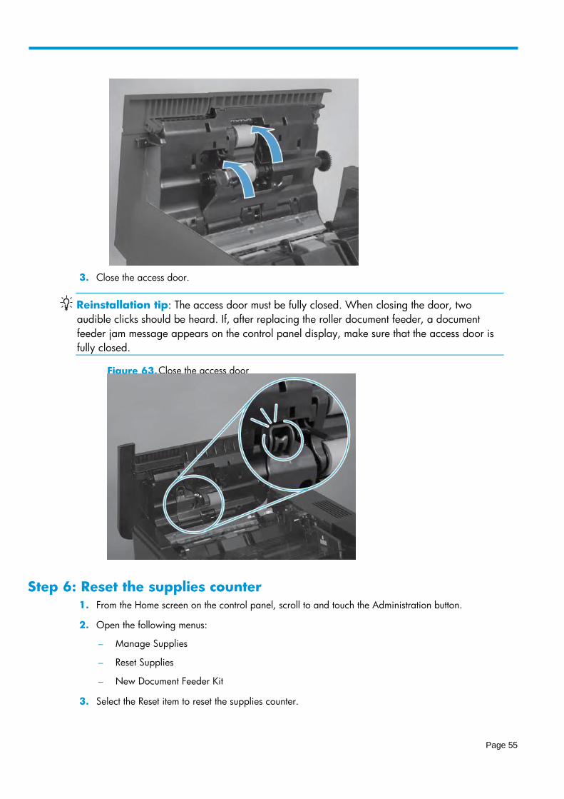
2. Rotate the roller up into the document feeder.
Figure 62. Rotate the roller up
4. Rotate the separation pad down unt il it snap in place.
Reinstallation tip When the pad is correctly installed, an audible click should be heard. :
Figure 60. Install the separation pad
Page 55
3. Close the access door.
Reinstallation tip: The access door must be fully closed. When closing the door, two
audible clicks should be heard. If, after replacing the roller document feeder, a document
feeder jam message appears on the control panel display, make sure that the access door is
fully closed.
Step 6: Reset the supplies counter
1. From the Home screen on the control panel, scroll to and touch the Administration button.
2. Open the following menus:
– Manage Supplies
– Reset Supplies
– New Document Feeder Kit
3. Select the Reset item to reset the supplies counter.
Figure 63. Close the access do or

Page 56
Parts Return Products return and recycling.