Laser-Printed and Processed LiCoO 2 CathodeThick Films for ...
6
JLMN-Journal of Laser Micro/Nanoengineering Vol. 7, No. 3, 2012 320 Laser-Printed and Processed LiCoO 2 CathodeThick Films for Li-Ion Microbatteries Heungsoo KIM *1 , Johannes PROELL *2 , Robert KOHLER *2 , Wilhelm PFLEGING *2,3 , and Alberto PIQUE *1 *1 1-Naval Research Laboratory, Washington DC, 20375, U.S.A E-mail: [email protected] *2 2- Karlsruhe Institute of Technology, IAM-AWP, P.O. Box 3640, 76021 Karlsruhe, Germany *3 3- Karlsruhe Nano Micro Facility, H.-von-Helmholtz-Platz 1, 76344 Egg.-Leopoldshafen, Germany Thick-film electrodes (LiCoO 2 cathode and carbon anode) are laser-printed onto metallic current collectors for fabricating Li-ion microbatteries. Microbatteries fabricated with these laser-printed thick-film electrodes demonstrate a significantly higher discharge capacity and power density than those made by sputter-deposited thin-film techniques. This increased performance is attributed to the porous structure of the laser-printed electrodes that allows improved ionic and electronic transport through the thick electrodes (up to ~100 µm) without a significant increase in internal re- sistance. Laser structuring process is applied to increase active surface area of the laser-printed LiCoO 2 cathode films for improving cycle stability of microbatteries at high charging/discharging currents. Laser structuring parameters, including laser pulse number and laser fluence, are optimized for improving surface morphology of the films. Keywords: Thick-film electrodes, Li-ion microbatteries, Laser direct-write, Laser structuring, 3D battery 1. Introduction In recent years, there is a strong demand for miniatur- ized rechargeable power sources for autonomous microe- lectronic devices such as wireless network microsensors. Thin-film Li and Li-ion microbatteries are being studied as a current-state-of-the-art micropower source due to their high operating voltages, high energy densities and long cycle life [1-3]. To date, these rechargeable thin-film mi- crobatteries have been prepared by physical deposition methods, such as sputtering [1-3], pulsed laser deposition (PLD) [4], chemical vapor deposition [5], and sol-gel [6] techniques. Among these, the sputtering techniques have been widely utilized because they can grow all battery components including cathode electrodes (lithium- transition metal oxides), anode electrodes (Li-metal), elec- trolyte/separator (commonly lithium phosphorous oxyni- tride, LIPON), and current collectors (Al or Cu). However, the sputtering techniques are not able to deposit traditional composite components (active material, carbon and electro- lyte) simultaneously, indicating that sputter-deposited cath- ode thin films (e.g. LiCoO 2 ) provide relatively small con- ductivity because of no conducting carbon in the films. In this matter, the thicknesses of the cathode films prepared by the sputtering techniques are typically limited to 1 to 5 µm in order to keep cell resistance low. Dudney and Jang demonstrate that Li-LiCoO 2 solid-state thin-film microbat- teries with a cathode thickness of 1 µm deliver as much as ~95 % of the maximum capacity, whereas the batteries with a 5 µm-thick cathode supply only 75 % of the maximum capacity [2]. The discharge capacity of the thicker LiCoO 2 cathode films decreases more rapidly with increasing dis- charge current density [2]. This is attributed to the relative- ly high internal cell resistance of the thicker, less conduct- ing cathodes, which limits the diffusivity of lithium ions. Because of this thickness limitation, the power and capaci- ty per active electrode area of the thin-film microbatteries are not sufficient to operate many microelectronic devices. In order to overcome the thickness limitation (i.e., low power and energy density) in thin-film microbatteries, the laser printing technique, which is a laser direct write (LDW) process, is used to develop thick-film electrodes. LDW allows for the fabrication of highly porous structured thick-film electrodes [7-10] without the use of any litho- graphic patterning steps. In LDW, a laser pulse is used to transfer or print 3-D pixels or voxels of an ink or paste con- taining a suspension of the electrode materials onto a sub- strate in order to form a pattern. Processing can convert the laser-printed patterns into a porous thick-film structure ideally suited for microbattery applications. Laser-printed electrodes could provide much higher capacities per elec- trode area than the sputter-deposited thin-film electrodes, since their porous structure allows better ionic and elec- tronic transport through the thick electrodes (~ 100 µm) without a significant internal resistance. The LDW tech- nique also can directly embed the electrochemical compo- nent into the substrates, reducing the size and weight of the microdevices [11]. Furthermore, this process can be com- bined with in situ laser annealing for processing the layers of active materials without damaging the substrate under- neath, which is ideally suited for developing power sources on flexible plastic substrates [12]. This LDW technique has successfully fabricated Li- and Li-ion microbatteries using
Transcript of Laser-Printed and Processed LiCoO 2 CathodeThick Films for ...

JLMN-Journal of Laser Micro/Nanoengineering Vol. 7, No. 3, 2012
320
Laser-Printed and Processed LiCoO2 CathodeThick Films for Li-Ion Microbatteries
Heungsoo KIM*1, Johannes PROELL*2, Robert KOHLER*2, Wilhelm PFLEGING*2,3, and Alberto PIQUE*1
*1 1-Naval Research Laboratory, Washington DC, 20375, U.S.A E-mail: [email protected]
*2 2- Karlsruhe Institute of Technology, IAM-AWP, P.O. Box 3640, 76021 Karlsruhe, Germany *3 3- Karlsruhe Nano Micro Facility, H.-von-Helmholtz-Platz 1, 76344 Egg.-Leopoldshafen, Germany
Thick-film electrodes (LiCoO2 cathode and carbon anode) are laser-printed onto metallic current collectors for fabricating Li-ion microbatteries. Microbatteries fabricated with these laser-printed thick-film electrodes demonstrate a significantly higher discharge capacity and power density than those made by sputter-deposited thin-film techniques. This increased performance is attributed to the porous structure of the laser-printed electrodes that allows improved ionic and electronic transport through the thick electrodes (up to ~100 µm) without a significant increase in internal re-sistance. Laser structuring process is applied to increase active surface area of the laser-printed LiCoO2 cathode films for improving cycle stability of microbatteries at high charging/discharging currents. Laser structuring parameters, including laser pulse number and laser fluence, are optimized for improving surface morphology of the films.
Keywords: Thick-film electrodes, Li-ion microbatteries, Laser direct-write, Laser structuring, 3D battery
1. Introduction In recent years, there is a strong demand for miniatur-ized rechargeable power sources for autonomous microe-lectronic devices such as wireless network microsensors. Thin-film Li and Li-ion microbatteries are being studied as a current-state-of-the-art micropower source due to their high operating voltages, high energy densities and long cycle life [1-3]. To date, these rechargeable thin-film mi-crobatteries have been prepared by physical deposition methods, such as sputtering [1-3], pulsed laser deposition (PLD) [4], chemical vapor deposition [5], and sol-gel [6] techniques. Among these, the sputtering techniques have been widely utilized because they can grow all battery components including cathode electrodes (lithium-transition metal oxides), anode electrodes (Li-metal), elec-trolyte/separator (commonly lithium phosphorous oxyni-tride, LIPON), and current collectors (Al or Cu). However, the sputtering techniques are not able to deposit traditional composite components (active material, carbon and electro-lyte) simultaneously, indicating that sputter-deposited cath-ode thin films (e.g. LiCoO2) provide relatively small con-ductivity because of no conducting carbon in the films. In this matter, the thicknesses of the cathode films prepared by the sputtering techniques are typically limited to 1 to 5 µm in order to keep cell resistance low. Dudney and Jang demonstrate that Li-LiCoO2 solid-state thin-film microbat-teries with a cathode thickness of 1 µm deliver as much as ~95 % of the maximum capacity, whereas the batteries with a 5 µm-thick cathode supply only 75 % of the maximum capacity [2]. The discharge capacity of the thicker LiCoO2 cathode films decreases more rapidly with increasing dis-
charge current density [2]. This is attributed to the relative-ly high internal cell resistance of the thicker, less conduct-ing cathodes, which limits the diffusivity of lithium ions. Because of this thickness limitation, the power and capaci-ty per active electrode area of the thin-film microbatteries are not sufficient to operate many microelectronic devices. In order to overcome the thickness limitation (i.e., low power and energy density) in thin-film microbatteries, the laser printing technique, which is a laser direct write (LDW) process, is used to develop thick-film electrodes. LDW allows for the fabrication of highly porous structured thick-film electrodes [7-10] without the use of any litho-graphic patterning steps. In LDW, a laser pulse is used to transfer or print 3-D pixels or voxels of an ink or paste con-taining a suspension of the electrode materials onto a sub-strate in order to form a pattern. Processing can convert the laser-printed patterns into a porous thick-film structure ideally suited for microbattery applications. Laser-printed electrodes could provide much higher capacities per elec-trode area than the sputter-deposited thin-film electrodes, since their porous structure allows better ionic and elec-tronic transport through the thick electrodes (~ 100 µm) without a significant internal resistance. The LDW tech-nique also can directly embed the electrochemical compo-nent into the substrates, reducing the size and weight of the microdevices [11]. Furthermore, this process can be com-bined with in situ laser annealing for processing the layers of active materials without damaging the substrate under-neath, which is ideally suited for developing power sources on flexible plastic substrates [12]. This LDW technique has successfully fabricated Li- and Li-ion microbatteries using
Hiromi
タイプライターテキスト
DOI:10.2961/jlmn.2012.03.0016
JLMN-Journal of Laser Micro/Nanoengineering Vol. 7, No. 3, 2012
321
LiCoO2 cathodes, carbon or Li anodes, and laser-transferable polymer-ionic liquid separator/electrolytes and liquid electrolytes [10,11,13]. In this study, we demonstrate an order of magnitude higher discharge capacities for Li-ion microbatteries fabricated with gel polymer electrolytes and much thicker electrodes (25 – 105 µm). Three dimensional battery architectures have been pro-posed to enhance the power density while maintaining high energy density of micro-battery systems [14-16]. Applica-tions of 3D-batteries include smart card devices, radio-frequency identification (RFID) chips and microelectrome-chanical systems (MEMS) and micro-spacecraft [17-19]. As manufacturing process of the 3D architectures substrate structuring, usually silicon, has been discussed [20, 21]. Very recently, laser structuring processes for thin films have been developed allowing the formation of micro-structures directly out of the active electrode material such as lithium cobalt oxide (LiCoO2) [22], lithium manganese oxide [23] and tin oxide [24]. For LiCoO2 thin films creat-ed via magnetron sputtering and also for commercially available LiCoO2 tape cast electrodes, the occurrence of laser-induced self-organizing surface structures has been reported [22,25]. In this paper, we detail the high discharge capacity of Li-ion microbatteries, fabricated using laser-printed thick-film electrodes (LiCoO2 cathode and carbon anode). The influence of electrode thickness on the battery performance is then studied. High discharge capacities of ~2.4 mAh/cm2 are demonstrated with thick LiCoO2 cathodes (~105 µm). The performance of the thick-film Li-ion microbatteries is also compared with those results reported in the literature for microbatteries prepared by sputter-deposited thin-film electrodes. Finally, these laser-printed LiCoO2 thick films are further treated with laser structuring process for in-creasing active surface area and improved capacity reten-tion is observed for the batteries fabricated with the laser structured films.
2. Experimental
2.1 Electrode Materials The cathode ink is formulated by mixing 91% LiCoO2 (CO22, Seimi), 4% graphite (KS6, Timcal), 2% carbon black (Super P, Erachem) in a solution of 3% PVdF-HFP (Kynar 2801, Elf Atochem) in dibasic ester (DBE, a blend comprised of 59 wt. % dimethyl gluturate, 21 wt. %, dime-thyl adipate, and 20 wt. % dimethyl succinate, Du Pont) solvent. The anode ink is prepared by mixing 91% carbon (MCMB 2528, Osaka Gas: MCMB stands for mesocarbon microbeads), 1% carbon black, and 8% PVdF-HFP in DBE solvent. In the electrode formulation, the graphite (KS6) is added to improve the electric conductivity and the carbon black (Super P) is added to increase porosity in the elec-trode films. The PVDF-HFP is used as a binder to hold the electrode films onto current collectors. The DBE is selected because it is a good solvent for PVDF binder and its boil-ing temperature is relatively high (~210 °C). The cathode and anode electrodes are laser-printed onto 50 µm thick Al and Cu current collectors, respectively.
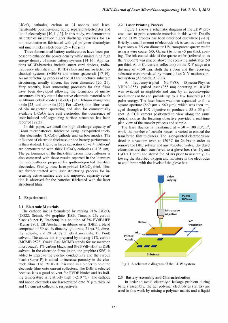
2.2 Laser Printing Process Figure 1 shows a schematic diagram of the LDW pro-
cess used to print electrode materials in this work. Details of the LDW process has been described elsewhere [7-10]. Briefly, a small amount of electrode ink is cast as a uniform layer onto a 7.5 cm diameter UV transparent quartz wafer using a wire coater (#5, Garner) to form ~5 μm thick coat-ing. The ink coated side of the quartz wafer (referred to as the “ribbon”) was placed above the receiving substrates (50 μm thick Al or Cu current collectors) on the X-Y stage at a distance of ~150 µm. Both the ribbon and the receiving substrate were translated by means of an X-Y motion con-trol system (Aerotech, A3200).
A frequency-tripled Nd:YVO4 (Spectra-Physics YHP40-355) pulsed laser (355 nm) operating at 10 kHz was switched in amplitude and time by an acousto-optic modulator (AOM) to provide up to a few hundred µJ of pulse energy. The laser beam was then expanded to fill a square aperture (560 µm x 560 µm), which was then im-aged through a 10X objective to produce a 55 x 55 µm2 spot. A CCD camera positioned to view along the same optical axis as the focusing objective provided a real-time plan view of the transfer process and sample.
The laser fluence is maintained at ~ 50 – 100 mJ/cm2, while the number of transfer passes is varied to control the transferred film thickness. The laser-printed electrodes are dried in a vacuum oven at 120 °C for 24 hrs in order to remove the DBE solvent and any absorbed water. The dried electrodes are then transferred to a glove box (Ar, O2 and H2O < 1 ppm) and stored for 24 hrs prior to assembly, al-lowing the absorbed oxygen and moisture in the electrodes to equilibrate with the levels of the glove box.
Fig.1. A schematic diagram of the LDW system.
2.3 Battery Assembly and Characterization In order to avoid electrolyte leakage problem during
battery assembly, the gel polymer electrolytes (GPEs) are used in this work by mixing a polymer matrix and a liquid
X-Ytranslation
Pulsed UV laser
VideoImaging
Microscopeobjective
Ink
Substrate
Printedvoxels
Ribbon

JLMN-Journal of Laser Micro/Nanoengineering Vol. 7, No. 3, 2012
322
electrolyte. PVdF-HFP is used as the polymer matrix for the GPE. A solution of 1 M LiPF6 (Aldrich) in propylene carbonate (PC)/ethylene carbonate (EC)/dimethyl car-bonate (DMC) (1:1:3 by volume, used as received from Aldrich) is used as a liquid electrolyte. PVdF-HFP powder is dissolved into the liquid electrolyte solution by stirring at 60°C. A polyolefin based microporous membrane (E25MMS SETELA, Tonen Chemical Corp.) is used as a separator. The 25 µm thick membrane is immersed in the GPE solution for 20 min inside the glove box.
The active area of the printed electrodes is 0.49 cm2. The current collectors are cut out to 1.3 cm x 1.3 cm using a laser.The Li-ion microbatteries used for this work are assembled by placing the GPE soaked porous membrane between the LiCoO2 cathode and the MCMB anode. In order to package the stacked assembly, the current collec-tors are sealed together with a thermally curable polymer spacer (Surlyn SF-71, Flex-O-Glass) placed along each edge of the active electrode area (7 mm x 7 mm). The seal-ing is performed by hot pressing the thermally curable pol-ymer at ~ 100°C for 10 sec and then followed by immedi-ate cold pressing in order to avoid the crystallization of the sealing polymer, which could result in pinhole leaks in the seal. Figure 2 shows a cross sectional schematic diagram of an assembled Li-ion microbattery. Microbatteries are cy-cled between 4.2 V and 3 V at a constant current of 100 µA/cm2 using an Arbin battery tester (BT2000, Arbin In-struments) with MITS Pro 3.0 software.
Fig.2. Cross-sectional schematic diagram (not to scale) of a typical Li-ion microbattery used in this research.
2.4 Laser Structuring and battery characterization Figure 3(a) shows a schematic diagram of the laser struc-
turing system used in this work. Laser patterning and sur-face modification is performed using a KrF-excimer laser (ATLEX-500-SI, ATL Laser- technik) operating at a wave-length of 248 nm. The laser pulse length is 5 ns (FWHM). The laser beam with a flat-top profile is projected onto the sample surface using a demagnifying lens (demagnification factor 10:1) with a numerical aperture of 0.4. Scanning electron microscope (SEM) images are taken with a XL30S (Philips) under an angle of 45°.
Electrochemical characterization of the laser structured LiCoO2 cathode films is performed using Swagelok® cells and an Arbin Instruments BT2000 battery testing system. Figure 3(b) illustrates a Swagelok® cell used in this work. The Swagelok holders (product number: SS-12M0-6) are
made of stainless steel with an inner diameter of 12 mm. The plungers are also made of stainless steel with a diame-ter of 12 mm. The sealing rings are made of PTFE and a GF/A separator (thickness 260 µm, Whatman) is applied between the cathode and anode films. The metallic lithium foil (thickness 350µm, Sigma Aldrich) is used as anode material and pressed onto a nickel substrate (thickness 500µm) in order to achieve good electrical contact. A spring is inserted between the nickel substrate and the plunger in order to achieve a constant and reproducible mechanical force of 18.80 N. The electrolyte is conven-tional ethylene carbonate / dimethyl carbonate electrolyte containing 1M LiPF6. For laser structuring test and also Swagelok cell test, current collectors are cut out to 12 mm in diameter and the active area of LiCoO2 electrodes is 0.785 cm2. Battery cycling is performed at a constant cur-rent between 3.0 V and 4.2 V. The applied current corre-sponds to a C-rate of C/5, when assuming a theoretical ca-pacity of 140 mAh/g. A “C/5” rate means that the dis-charge current will discharge the entire battery in 5 hours.
Fig.3. (a) A schematic illustration of the laser structuring sys-tem. (b) a schematic illustration of the Swagelok cell design.
3. Results and Discussion
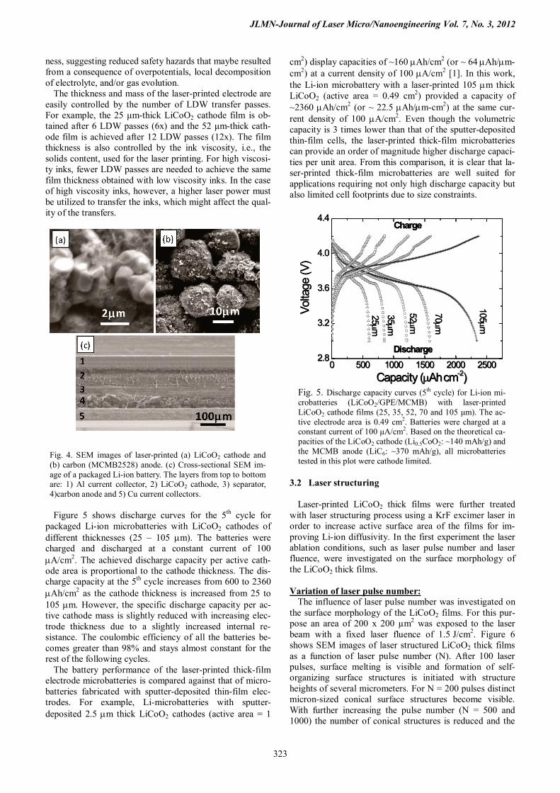
3.1 Laser-printed thick-film electrodes Figure 4 shows SEM images from the laser printed cath-ode (LiCoO2 + graphite + carbon black) and anode (MCMB 2528 + carbon black) layers. The agglomerated LiCoO2 powder grains mixed with the much smaller graph-ite and carbon black are clearly seen in Fig. 4(a), while the MCMB 2528 spherical particles mixed with the smaller carbon black can be observed in Fig. 4(b). Both SEM im-ages also show the highly porous structure of both layers. This high porous structure allows improved ionic and elec-tronic transport without a significant increase in cell inter-nal resistance. Figure 4(c) shows a cross sectional SEM image of a packaged Li-ion battery. It is clear that each layers exhibit homogeneous structure with uniform thick-
JLMN-Journal of Laser Micro/Nanoengineering Vol. 7, No. 3, 2012
323
ness, suggesting reduced safety hazards that maybe resulted from a consequence of overpotentials, local decomposition of electrolyte, and/or gas evolution.
The thickness and mass of the laser-printed electrode are easily controlled by the number of LDW transfer passes. For example, the 25 μm-thick LiCoO2 cathode film is ob-tained after 6 LDW passes (6x) and the 52 μm-thick cath-ode film is achieved after 12 LDW passes (12x). The film thickness is also controlled by the ink viscosity, i.e., the solids content, used for the laser printing. For high viscosi-ty inks, fewer LDW passes are needed to achieve the same film thickness obtained with low viscosity inks. In the case of high viscosity inks, however, a higher laser power must be utilized to transfer the inks, which might affect the qual-ity of the transfers.
Fig. 4. SEM images of laser-printed (a) LiCoO2 cathode and (b) carbon (MCMB2528) anode. (c) Cross-sectional SEM im-age of a packaged Li-ion battery. The layers from top to bottom are: 1) Al current collector, 2) LiCoO2 cathode, 3) separator, 4)carbon anode and 5) Cu current collectors.
Figure 5 shows discharge curves for the 5th cycle for
packaged Li-ion microbatteries with LiCoO2 cathodes of different thicknesses (25 – 105 µm). The batteries were charged and discharged at a constant current of 100 µA/cm2. The achieved discharge capacity per active cath-ode area is proportional to the cathode thickness. The dis-charge capacity at the 5th cycle increases from 600 to 2360 µAh/cm2 as the cathode thickness is increased from 25 to 105 µm. However, the specific discharge capacity per ac-tive cathode mass is slightly reduced with increasing elec-trode thickness due to a slightly increased internal re-sistance. The coulombic efficiency of all the batteries be-comes greater than 98% and stays almost constant for the rest of the following cycles.
The battery performance of the laser-printed thick-film electrode microbatteries is compared against that of micro-batteries fabricated with sputter-deposited thin-film elec-trodes. For example, Li-microbatteries with sputter-deposited 2.5 µm thick LiCoO2 cathodes (active area = 1
cm2) display capacities of ~160 µAh/cm2 (or ~ 64 µAh/µm-cm2) at a current density of 100 µA/cm2 [1]. In this work, the Li-ion microbattery with a laser-printed 105 µm thick LiCoO2 (active area = 0.49 cm2) provided a capacity of ~2360 µAh/cm2 (or ~ 22.5 µAh/µm-cm2) at the same cur-rent density of 100 µA/cm2. Even though the volumetric capacity is 3 times lower than that of the sputter-deposited thin-film cells, the laser-printed thick-film microbatteries can provide an order of magnitude higher discharge capaci-ties per unit area. From this comparison, it is clear that la-ser-printed thick-film microbatteries are well suited for applications requiring not only high discharge capacity but also limited cell footprints due to size constraints.
0 500 1000 1500 2000 25002.8
3.2
3.6
4.0
4.4
25µm
35µm
52µm
70µm
105µm
Volta
ge (V
)
Capacity (µAh cm-2)
Discharge
Charge
0 500 1000 1500 2000 25002.8
3.2
3.6
4.0
4.4
25µm
35µm
52µm
70µm
105µm
Volta
ge (V
)
Capacity (µAh cm-2)
Discharge
Charge
Fig. 5. Discharge capacity curves (5th cycle) for Li-ion mi-crobatteries (LiCoO2/GPE/MCMB) with laser-printed LiCoO2 cathode films (25, 35, 52, 70 and 105 μm). The ac-tive electrode area is 0.49 cm2. Batteries were charged at a constant current of 100 μA/cm2. Based on the theoretical ca-pacities of the LiCoO2 cathode (Li0.5CoO2: ~140 mAh/g) and the MCMB anode (LiC6: ~370 mAh/g), all microbatteries tested in this plot were cathode limited.
3.2 Laser structuring Laser-printed LiCoO2 thick films were further treated with laser structuring process using a KrF excimer laser in order to increase active surface area of the films for im-proving Li-ion diffusivity. In the first experiment the laser ablation conditions, such as laser pulse number and laser fluence, were investigated on the surface morphology of the LiCoO2 thick films. Variation of laser pulse number:
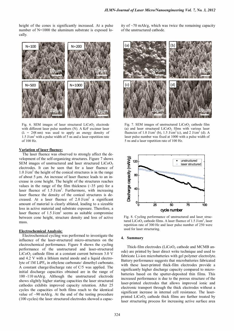
The influence of laser pulse number was investigated on the surface morphology of the LiCoO2 films. For this pur-pose an area of 200 x 200 µm2 was exposed to the laser beam with a fixed laser fluence of 1.5 J/cm2. Figure 6 shows SEM images of laser structured LiCoO2 thick films as a function of laser pulse number (N). After 100 laser pulses, surface melting is visible and formation of self-organizing surface structures is initiated with structure heights of several micrometers. For N = 200 pulses distinct micron-sized conical surface structures become visible. With further increasing the pulse number (N = 500 and 1000) the number of conical structures is reduced and the
JLMN-Journal of Laser Micro/Nanoengineering Vol. 7, No. 3, 2012
324
height of the cones is significantly increased. At a pulse number of N=1000 the aluminum substrate is exposed lo-cally.
Fig. 6. SEM images of laser structured LiCoO2 electrode with different laser pulse numbers (N). A KrF excimer laser (λ = 248 nm) was used to apply an energy density of 1.5 J/cm2 with a pulse width of 5 ns and a laser repetition rate of 100 Hz.
Variation of laser fluence:
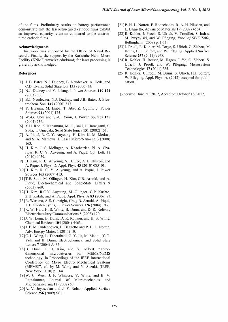
The laser fluence was observed to strongly affect the de-velopment of the self-organizing structures. Figure 7 shows SEM images of unstructured and laser structured LiCoO2 electrodes. It can be seen that for a laser fluence of 1.0 J/cm2 the height of the conical structures is in the range of about 5 µm. An increase of laser fluence leads to an in-crease in cone height. The height of the structures reaches values in the range of the film thickness (~35 μm) for a laser fluence of 1.5 J/cm2. Furthermore, with increasing laser fluence the density of the conical structures is de-creased. At a laser fluence of 2.0 J/cm2 a significant amount of material is clearly ablated, leading to a sizeable loss in active material and substrate exposure. Therefore, a laser fluence of 1.5 J/cm2 seems as suitable compromise between cone height, structure density and loss of active mass.
Electrochemical Analysis:
Electrochemical cycling was performed to investigate the influence of the laser-structured micro-structures on the electrochemical performance. Figure 8 shows the cycling performance of the unstructured and laser-structured LiCoO2 cathode films at a constant current between 3.0 V and 4.2 V with a lithium metal anode and a liquid electro-lyte of 1M LiPF6 in ethylene carbonate/ dimethyl carbonate. A constant charge/discharge rate of C/5 was applied. The initial discharge capacities obtained are in the range of 100 -110 mAh/g. Although the unstructured electrode shows slightly higher starting capacities the laser structured cathodes exhibits improved capacity retention. After 25 cycles the capacities of both films reach to the identical value of ~90 mAh/g. At the end of the testing procedure (100 cycles) the laser structured electrodes showed a capac-
ity of ~70 mAh/g, which was twice the remaining capacity of the unstructured cathode.
Fig. 7. SEM images of unstructured LiCoO2 cathode film (a) and laser structured LiCoO2 films with various laser fluencies of 1.0 J/cm2 (b), 1.5 J/cm2 (c), and 2 J/cm2 (d). A laser pulse number was fixed at 1000 with a pulse width of 5 ns and a laser repetition rate of 100 Hz.
Fig. 8. Cycling performance of unstructured and laser struc-tured LiCoO2 cathode films. A laser fluence of 1.5 J/cm2, laser repetition rate of 300 Hz and laser pulse number of 250 were used for laser structuring.
4. Summary
Thick-film electrodes (LiCoO2 cathode and MCMB an-
ode) are printed by laser direct write technique and used to fabricate Li-ion microbatteries with gel polymer electrolyte. Battery performance suggests that microbatteries fabricated with these laser-printed thick-film electrodes provide a significantly higher discharge capacity compared to micro-batteries based on the sputter-deposited thin films. This increased performance is due to the porous structure of the laser-printed electrodes that allows improved ionic and electronic transport through the thick electrodes without a significant increase in internal cell resistance. The laser-printed LiCoO2 cathode thick films are further treated by laser structuring process for increasing active surface area
0 25 50 75 1000
40
80
120
unstructured laser structured
Disc
harg
e ca
pacit
y (m
Ah/g
)
cycle number0 25 50 75 100
0
40
80
120
unstructured laser structured
Disc
harg
e ca
pacit
y (m
Ah/g
)
cycle number
JLMN-Journal of Laser Micro/Nanoengineering Vol. 7, No. 3, 2012
325
of the films. Preliminary results on battery performance demonstrate that the laser-structured cathode films exhibit an improved capacity retention compared to the unstruc-tured cathode films.
Acknowledgments
This work was supported by the Office of Naval Re-search. Finally, the support by the Karlsruhe Nano Micro Facility (KNMF, www.kit.edu/knmf) for laser processing is gratefully acknowledged. References [1] J. B. Bates, N.J. Dudney, B. Neudecker, A. Ueda, and
C.D. Evans, Solid State Ion. 135 (2000) 33. [2] N.J. Dudney and Y.-I. Jang, J. Power Sources 119-121
(2003) 300. [3] B.J. Neudecker, N.J. Dudney, and J.B. Bates, J. Elec-
trochem. Soc. 147 (2000) 517. [4] Y. Iriyama, M. Inaba, T. Abe, Z. Ogumi, J. Power
Sources 94 (2001) 175. [5] W.-G. Choi and S.-G. Yoon, J. Power Sources 125
(2004) 236. [6] Y.H. Rho, K. Kanamura, M. Fujisaki, J. Hamagami, S.
Suda, T. Umegaki, Solid State Ionics 151 (2002) 151. [7] A. Piqué, R. C. Y. Auyeung, H. Kim, K. M. Metkus,
and S. A. Mathews, J. Laser Micro/Nanoeng 3 (2008) 163.
[8] H. Kim, J. S. Melinger, A. Khachatrian, N. A. Cha-ripar, R. C. Y. Auyeung, and A. Piqué, Opt. Lett. 35 (2010) 4039.
[9] H. Kim, R. C. Auyeung, S. H. Lee, A. L. Huston, and A. Piqué, J. Phys. D: Appl. Phys. 43 (2010) 085101.
[10] H. Kim, R. C. Y. Auyeung, and A. Piqué, J. Power Sources 165 (2007) 413.
[11] T.E. Sutto, M. Ollinger, H. Kim, C.B. Arnold, and A. Piqué, Electrochemical and Solid-State Letters 9 (2005) A69.
[12] H. Kim, R.C.Y. Auyeung, M. Ollinger, G.P. Kushto, Z.H. Kafafi, and A. Piqué, Appl. Phys. A 83 (2006) 73.
[13] R. Wartena, A.E. Curtright, Craig B. Arnold, A. Piqué, K.E. Swider-Lyons, J. Power Sources 126 (2004) 193.
[14] R. W. Hart, H. S. White, B. Dunn, and D. R. Rolison, Electrochemistry Communications 5 (2003) 120.
[15] J. W. Long, B. Dunn, D. R. Rolison, and H. S. White, Chemical Reviews 104 (2004) 4463.
[16] J. F. M. Oudenhoven, L. Baggetto and P. H. L. Notten, Adv. Energy Mater. 1 (2011) 10.
[17] C. L. Wang, L. Taherabadi, G. Y. Jia, M. Madou, Y. T. Yeh, and B. Dunn, Electrochemical and Solid State Letters 7 (2004) A435.
[18] B. Dunn, C. J. Kim, and S. Tolbert, “Three-dimensional microbatteries for MEMS/NEMS technology, in Proceedings of the IEEE International Conference on Micro Electro Mechanical Systems (MEMS)”, ed. by M. Wong and Y. Suzuki, (IEEE, New York, 2010) p. 164.
[19] W. C. West, J. F. Whitacre, V. White, and B. V. Ratnakumar, Journal of Micromechanics and Microengineering 12,(2002) 58.
[20] A. V. Jeyaseelan and J. F. Rohan, Applied Surface Science 256 (2009) S61.
[21] P. H. L. Notten, F. Roozeboom, R. A. H. Niessen, and L. Baggetto, Advanced Materials 19 (2007) 4564.
[22] R. Kohler, J. Proell, S. Ulrich, V. Trouillet, S. Indris, M. Przybylski, and W. Pfleging, Proc. of SPIE 7202, Bellingham, (2009) p. 1-11.
[23] J. Proell, R. Kohler, M. Torge, S. Ulrich, C. Ziebert, M. Bruns, H. J. Seifert, and W. Pfleging, Applied Surface Science 257 (2011) 9968.
[24] R. Kohler, H. Besser, M. Hagen, J. Ye, C. Ziebert, S. Ulrich, J. Proell, and W. Pfleging, Microsystem Technologies 17 (2011) 225.
[25] R. Kohler, J. Proell, M. Bruns, S. Ulrich, H.J. Seifert, W. Pfleging, Appl. Phys. A, (2012) accepted for publi-cation.
(Received: June 30, 2012, Accepted: October 16, 2012)