
Large and Small Break LOCA Analysis/Result · PDF fileLarge and Small Break LOCA...
33
11/1/06 22.39 Lecture 15: Large Break LOCA Analysis/Result Professor Neil Todreas 1 Large and Small Break LOCA Analysis/Result Course 22.39, Lecture 15 11/1/06 Professor Neil Todreas
Transcript of Large and Small Break LOCA Analysis/Result · PDF fileLarge and Small Break LOCA...
11/1/06 22.39 Lecture 15: Large Break LOCA Analysis/Result Professor Neil Todreas
1
Large and Small Break LOCA Analysis/Result
Course 22.39, Lecture 1511/1/06
Professor Neil Todreas
Professor Neil Todreas
2
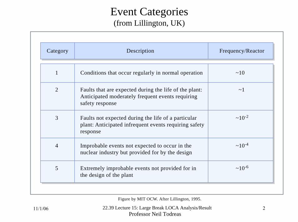
DescriptionCategory Frequency/Reactor
2 ~1
3 ~10-2
1 ~10
4 ~10-4
5 ~10-6
Faults that are expected during the life of the plant: Anticipated moderately frequent events requiring safety response
Faults not expected during the life of a particular plant: Anticipated infrequent events requiring safety response
Conditions that occur regularly in normal operation
Improbable events not expected to occur in the nuclear industry but provided for by the design
Extremely improbable events not provided for in the design of the plant
Event Categories (from Lillington, UK)
Figure by MIT OCW. After Lillington, 1995.
11/1/06 222.39 Lecture 15: Large Break LOCA Analysis/Result

Professor Neil Todreas3
Example Events(from Lillington, UK)
Events Categories
Loss of External GridLoss of FeedwaterLoss of Reactor Coolant Pump
Small LOCAValves Open
Bringing the Reactor to Full Power
Large LOCAMain Steam Line Break
2
3
1
4
LOCAs without ECCSTransients with Total Loss of ON- and Off-Site Power
5
Figure by MIT OCW. After Lillington, 1995.
11/1/06 22.39 Lecture 15: Large Break LOCA Analysis/Result

22.39 Lecture 15: Large Break LOCA AnalysidResult Professor Neil Todreas
Bleed and Feed
High pressure make-up water supply at ambienttemperature
Primary coolant circuit
Heat input from core Mass lost as water = BAD
High mass flow rate Low enthalpy change
Mass lost as steam = GOODLow mass flow rateHigh enthalpy change
Energy Outflows as Steam and Water
Figure by MIT OCW.

11/1/06 22.39 Lecture 15: Large Break LOCA Analysis/Result Professor Neil Todreas
505-017
Decay Power and Integral Decay Power As A Function of Time
0.01 0.02 0.05 0.1 0.2 0.5 1.0 2.0 5.0 10 20 50 100
Time (d)
0.001
0.002
0.005
0.01
0.02
0.05
0.1
Dec
ay P
ower
[MW
(th)]/
[MW
(th) R
eact
or O
utpu
t]
0.001
0.002
0.005
0.01
0.02
0.05
0.1
Inte
gral
Dec
ay P
ower
[MW
d]/[M
W(th
) Rea
ctor
Out
put]• Pressurized Water Reactor
• SNF Burnup: 33 GW(d)/MTIHM
By Charles Forsberg. Courtesy of Oak Ridge National Laboratory.
11/1/06 22.39 Lecture 15: Large Break LOCA Analysis/Result Professor Neil Todreas
6
Diagrammatic representation of PWR primary and secondary circuits and the emergency cooling systems
Diagram removed due to copyright restrictions.Figure 4.4 in Collier, J. G., and G. F. Hewitt. Introduction to Nuclear Power.Washington, DC: Hemisphere Publishing, 1987.
22.39 Lecture 15: Large Break LOCA AnalysisIResult Professor Neil Todreas
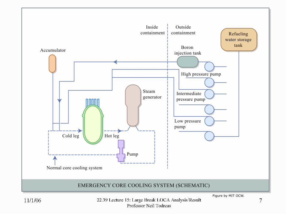
EMERGENCY CORE COOLING SYSTEM (SCHEMATIC)
Low pressure pump
Steam generator
Pump
Hot legCold leg
Accumulator
Inside containment
Outsidecontainment
Normal core cooling system
Intermediate pressure pump
High pressure pump
Boron injection tank
Refuelingwater storage
tank
Figure by MIT OCW.

11/1/06 22.39 Lecture 15: Large Break LOCA Analysis/Result Professor Neil Todreas
8
Connection pipe diameter/cross section/percentage spectrum of a PWR. (Solid lines) Primary loop system; (dashed lines) pressurizer
Diagram removed due to copyright restrictions.Figure 4.21 in Collier, J. G., and G. F. Hewitt. Introduction to Nuclear Power.Washington, DC: Hemisphere Publishing, 1987.

11/1/06 22.39 Lecture 15: Large Break LOCA Analysis/Result Professor Neil Todreas
9
Appendix C: Basic Assumptions of the LOCA1. The reactor has been operating for an infinite period of time
at an assumed slight overpower condition. No power or other transient preceeds the accident.
2. Peak core power density or linear power generation is at the maximum allowable value.
3. A double-ended rupture of one primary coolant loop is assumed (largest existing pipe)
PWR: rupture of cold leg imposes most severe conditionsBWR: rupture of a recirculation loopRemaining intact loops continue their operation as dictated by available electric supply or stored rotational energy.
4. Off-site power is lost upon initiation of the accident and is restored after several days. (continued)

11/1/06 22.39 Lecture 15: Large Break LOCA Analysis/Result Professor Neil Todreas
10
5. Reactor scram systems need not contribute to the nuclear shut down because voiding of the core provides sufficient negative reactivity for shutdown.
6. The reactor is isolated after the initiation of the accident, i.e. the regular heat sink is removed.
PWR: Upon initiation of the accident the steam generators are isolated on the secondary side by closing the steam supply valves and the feedwater valves.
BWR: Upon receipt of a reactor-vessel low-water signal the main steam isolation valves close within 10 seconds. Feedwater flow ramps to zero within four seconds. (continued)

11/1/06 22.39 Lecture 15: Large Break LOCA Analysis/Result Professor Neil Todreas
11
7. EECS are actuated automatically by appropriate signals. No corrective operator action is assumed for the first 10 minutes following initiation of the accident.
8. A single failure criterion is applied to the reactor system whereby an additional fault is postulated which may render inoperative any one of the following:
Mechanical active components (e.g. pump)
Active or passive electrical components

11/1/06 22.39 Lecture 15: Large Break LOCA Analysis/Result Professor Neil Todreas
12
Events in the reactor pressure vessel during a large-break LOCA. a) Normal operation; b) blowdown phase; c) refill phase; d) reflood phase
Diagram removed due to copyright restrictions.Figure 4.18 in Collier, J. G., and G. F. Hewitt. Introduction to Nuclear Power.Washington, DC: Hemisphere Publishing, 1987.
11/1/06 22.39 Lecture 15: Large Break LOCA Analysis/Result Professor Neil Todreas
13
PWR operating conditions
Diagram removed due to copyright restrictions.Figure 4.5 in Collier, J. G., and G. F. Hewitt. Introduction to Nuclear Power.Washington, DC: Hemisphere Publishing, 1987.

Cold Leg Break Steam Flow Path
Courtesy of Westinghouse. Used with permission.
22.39 Lecture 15: Large Break LOCA AnalysisIResult Professor Neil Todreas
11/1/06 22.39 Lecture 15: Large Break LOCA Analysis/Result Professor Neil Todreas
15
Adiabatic heat-up for PWR fuel (17 x 17)
Diagram removed due to copyright restrictions.Figure 4.1 in Collier, J. G., and G. F. Hewitt. Introduction to Nuclear Power.Washington, DC: Hemisphere Publishing, 1987.

11/1/06 22.39 Lecture 15: Large Break LOCA Analysis/Result Professor Neil Todreas
16
NRC Appendix K Criteria1) Peak Cladding Temperature. The calculated maximum fuel element
cladding temperature shall not exceed 2200° F.2) Maximum Cladding Oxidation. The calculated total oxidation of the
cladding shall nowhere exceed 0.17 times the total cladding thickness before oxidation.
3) Maximum Hydrogen Generation. The calculated total amount of hydrogen generated from the chemical reaction of the cladding with water or steam shall not exceed 0.01 times the hypothetical amount that would be generated if all the metal in the cladding cylinders surrounding the fuel, excluding the cladding surrounding the plenum volume, were to react.
4) Coolable Geometry. Calculated changes in core geometry shall be such that the core remains amenable to cooling.
5) Long-Term Cooling. After any calculated successful initial operation of the ECCS, the calculated core temperature shall be maintained at an acceptable low value and decay heat removed for the extended period of time required by the long-lived radioactivity remaining in the core.

11/1/06 22.39 Lecture 15: Large Break LOCA Analysis/Result Professor Neil Todreas
17
Variation of peak clad temperature with time for a large-break LOCA
Diagram removed due to copyright restrictions.Figure 4.19 in Collier, J. G., and G. F. Hewitt. Introduction to Nuclear Power.Washington, DC: Hemisphere Publishing, 1987.
11/1/06 22.39 Lecture 15: Large Break LOCA Analysis/Result Professor Neil Todreas
18
Schematic calculated fuel clad temperatures for a PWR LOCA
Diagram removed due to copyright restrictions.Figure 5-9 in Nero, A.V. A Guidebook to Nuclear Reactors.Berkeley, CA: University of California Press, 1979. ISBN: 0520034821
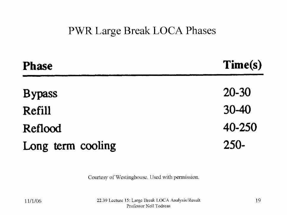
PWR Large Break LOCA Phases
Phase
Bypass Refill Reflood Long term cooling
Courtesy of Westinghouse. Used with permission
22.39 Lecture 15: Large Break LOCA Analysis/Result Professor Neil Todreas

LOCA Transient Periods
- - REFLOOD
BLOWDOWN - ~ E F I U
-
WSl - ACCUMULATOR lWECtlON INJECTION
1 I I 6 10 16 20 26 30 36 40
TIME (SEC)
Courtesy of Westinghouse. Used with permission.
22.39 Lecture 15: Large Break LOCA AnalysisIResult Professor Neil Todreas

Typical Conditions in Rod Bundle During Reflood
RFGlONrn FILM BOILING UNSTABLE
INTFRF ACE R E O I O N ~ . m lBolLlNG ZONE)
t 0
TRANSITION BOILING. VAPOR
I REOtONI
FILM SINGLE PHASE FORCES I t 1
CI(ICIID FLOW
FORMATION CONVECTION.NUCLEATE WILING
I ROO SURFACE TEMPERATURE
Hydrodynamic and HaM trmsfu Ragions Nan Ovarch Front
ROD
Courtesy of Westinghouse. Used with permission
22.39 Lecture 15: Large Break LOCA AnalysisIResult Professor Neil Todreas

South Texas FSAR Limiting Clad Temperature for LBLOCA STPEGS UFSAR
I Start of LOCA
, . - - - a 1 7 r - - T I
I 1 1 I 1 I 1 1 I 1 I I 1 1 1 ,
PeakClad Min.Clad End of Peak Clad Temp. Temp Beow- Temp. During During down Blowdown Blowdown
- - - - - :Ref.Core Analysis Results :Ref.Core FSAR Results
Source: Shuffler, C., J. Trant, N.E. Todreas, and A. Romano, Thermal Hydraulic and Economic Analysis of Grid-Supported, Hydride-Fueled PWRs (MIT-NFC-PR-077). Cambridge, M A : MIT CANES, January 2006
22.39 Lecture 15: Large Break LOCA AnalysisIResult Professor Neil Todreas

Analytic Estimate of PWR LBLOCA PCT
(Catton, I. et al. "Quantifying Reactor Safety Margines. Part 6. A Physically Based Method of Estimating PiVR LBLOCA PCT," NED 114 (1990) 104-1 17)
T,, = T, + Blowdown - ~ l ~ ~ d ~ ~ ~ +Refill + R e f l d Heating from convective decay decay heatup &cay heat & heatup and cooling Stored energy
Components u,, = +. 364 + 6 0 ! - 8 2 + 1 6 1 - 0 + 2 3 0 / - 5 5
Assumptions: q,' = 4.5 kwlft
Reflood rate = 4 inchedsec
Blowdovm p a k minus minimum clad temoeriture times = 20 sec
Source: Shuffler, C., J. Trant, N.E. Todreas, and A. Romano, Thermal Hydraulic andEconomic Analysis of Grid- Supported, Hydride-Fueled PWRs (MIT-NFC-PR-077). Cambridge, M A : MIT CANES, January 2006
22.39 Lecture 15: Large Break LOCA AnalysisIResult Professor Neil Todreas

24
Temperature at which significant phenomena occurduring core heat-up
Significant PhenomenonTemperature (oC)
350
800-150
Approximate cladding temperature during power operation.
1900 Zircaloy melts
1550-1650 Zircaloy-steam reaction may be autocatalytic unless Zircaloy is quenched by immersion.
2150 Increasingly significant fission product release from UO2
2700 UO2 and ZrO2 melt
1450-1500 Zircaloy steam reaction may produce energy in excess of decay heatGas absorption embrittles ZircaloyHydrogen formedSteel alloy melts
Rod internal gas pressure in the post-accident environment causes cladding to perforate or swell Some fission gases releaseSolid reactions begin stainless steels and ZircaloyClad swelling may block some flow channels
Figure by MIT OCW. After Hewitt and Collier.
11/1/06 22.39 Lecture 15: Large Break LOCA Analysis/Result Professor Neil Todreas

Best Estimate Large Break LOCA Analysis Results
I I I
t I I I
TE LARGE BREAX LOCA TIME SEQW3CE OF EVENTS
BEST ESCMATE M G E BREAK L O U ANALYSIS RESULTS
22.39 Lecture 15: Large Break LOCA AnalysisIResult Professor Neil Todreas
Courtesy of Westinghouse Used with permission.

Research Program to Address Appendix K Conservatisms Appendix K Requirement
Decay heat
Research Program -
ANS Decay Heat Standard Cmittee AMSI/ANS-5.1-1979
Zirconium-water oxidation ORNL - Reaction Rate Studles
EtC bypass BCL 1/15, 2/15 Scale Tests, Creare 1/15 Scale Tests
Post CHF heat transfer ORNL film boiling tests, senircale tests, University of Lehigh single tube tests
Reflood heat transfer Full length emergency core heat transfer (FLECHT) low flooding rate tests, FLECHT-SEASET (separate effects and systems effects test) tests
Steam binding during reflood FLECHT-SET phase B systems tests. semiscale. FLECHT-SEASET steam generator
tests, cylindrical core test facility reflood systems tests
Flow blockage heat transfe; FLECHT-SEASET 21-rod and 163-rod bundle
at low reflood rates tests. FEBA tests, HRU rod burst tests
No rewat after CHF until reflood Semiscale, loss of fluid test (LOFT) systems tests, Hestinghouse film boiling tests
Moody break flow model Harviken full scale critical flow tests, Courtesy of Westinghouse LOFT, semiscale Used with permission.
22.39 Lecture 15: Large Break LOCA Analysis/Result 26 Professor Neil Todreas

Small Break LOCA Strategy
I100 Mwe (3400 Mwt) =+ - 200 Mwt immediate decay heat generation
LPSI Steam generator if But if pressure too high use Feedwater avalldble HPSI andlor accumulators
* No auxiliary feedwater - PORV stack open
For pressure and inventory control
d' \
If break too small or water discharged increase break area
PORVs -top of pressurizer (0 .QQ2m21valve) Safety relief valves
Mass Flowrate -- ~ n t h a l p ~ h s s
22.39 Lecture 15: Large Break LOCA AnalysisIResult Professor Neil Todreas
Steam Discharge low high
Water Discharge high low
11/1/06 22.39 Lecture 15: Large Break LOCA Analysis/Result Professor Neil Todreas
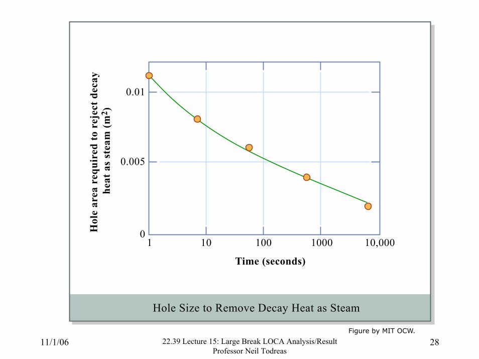
28
0.005
Hol
e ar
ea r
equi
red
to r
ejec
t dec
ay h
eat a
s st
eam
(m2 )
01 10 100
Time (seconds)
1000
Hole Size to Remove Decay Heat as Steam
10,000
0.01
Figure by MIT OCW.

PWR Small Break LOCA Phases
Phase Time(s)
Initial stage 0- 10 Ref lux condensation 10-220
Potential for first core uncovery 220-280 Loop seal clearing, potential for 280-3 10 core uncovery Long term cooling 3 10-
Courtesy of Westinghouse. Used with permission
11/1/06 22.39 Lecture 15: Large Break LOCA AnalysisIResult Professor Neil Todreas

11/1/06 22.39 Lecture 15: Large Break LOCA Analysis/Result Professor Neil Todreas
30
Primary pressure vs time for small-break LOCAs in a PWR. ( ) Primary temperature 175°C; ( ) reflood tank empty.
(Two HPI pumps; reflood tanks 4 x 286 m3; no LPI pumps)
Diagram removed due to copyright restrictions.Figure 4.22 in Collier, J. G., and G. F. Hewitt. Introduction to Nuclear Power.Washington, DC: Hemisphere Publishing, 1987.

11/1/06 22.39 Lecture 15: Large Break LOCA Analysis/Result Professor Neil Todreas
31
Small-break LOCA; mixture level and clad temperatures
Diagram removed due to copyright restrictions.Figure 4.27 in Collier, J. G., and G. F. Hewitt. Introduction to Nuclear Power.Washington, DC: Hemisphere Publishing, 1987.
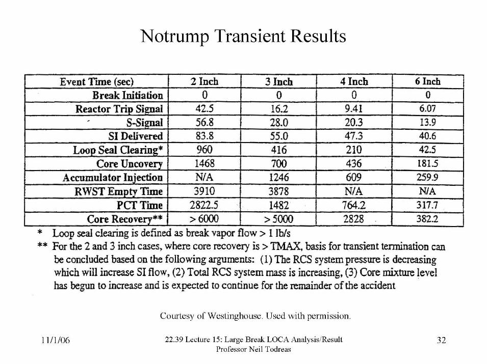
Notrump Transient Results
1 -- SI Delivered 1 83.8 1 55.0 1 47.3 1 4 0 . 6 1
Event T i e (sec) Break Initiation
Reactor T r i ~ Signal
Loop Seal Clearing* I 960 I 416 1 210 1 42.5 Core Uncoverv I 1468 700 436 1815
2 Inch 0
42.5
* Loop seal clearing is defined as break vapor flow > 1 Ibis
- . - - - - - -
Accumulator Injection RWST Empty Time
PCT Time
** For the 2 and 3 inch cases, where core recovery is > TMAX, basis for transient termination can be concluded based on the foliowing arguments: (1) The RCS system pressure is decreasing which will increase SI flow, (2) Total RCS system mass is increasing, (3) Core mixture level has begun to increase and is expected to continue for the remainder of the accident
3 Inch 0
16.2
Courtesy of Westinghouse. Used with permission
22.39 Lecture 15: Large Break LOCA AnalysisIResult Professor Neil Todreas
4 Inch 0
9.41
-.
6 1nch -- 0
6.07
N/ A 3910
-
Cote Recovery** 1 > 6000
1246 3878
609 N/A 764.2 2828 . > 5000
259.9 NIA 317.7 382.2
2822.5 1482
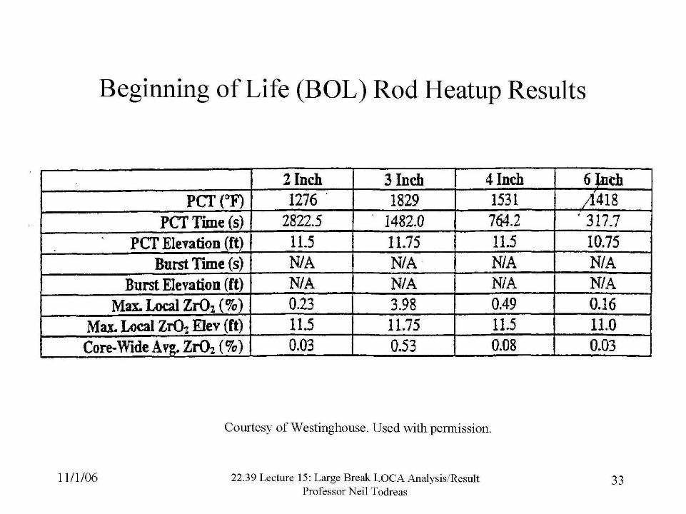
Beginning of Life (BOL) Rod Heatup Results
Courtesy of Westinghouse. Used with permission.
22.39 Lecture 15: Large Break LOCA AnalysisIResult Professor Neil Todreas
6 Jach b418 ' 317.7
10.75 Nl A NI A 0.16 11,O 0.03
PcT (OF) PCT T i e (s)
PCT Elevation (ft) Burst Time (s)
3 Inch 1829
1482.0 11.75 NIA N/A 3.98 11.75 0.53
2 Inch 1276
2822.5 11.5 N/ A
4 Inch 153 1 764.2 11.5 NIA N/A 0.49 11.5 0.08
Burst Elevation (ft) Max. Local ZrOz ( %) -
Max. Local Z G Elev (ft)
Nl A 0.23 11.5
Core-Wide Avg. ZrOz ( %) 1 0.03


![Loca Phenomena [Autosaved]](https://static.fdocuments.in/doc/165x107/55cf96c8550346d0338dc1cd/loca-phenomena-autosaved.jpg)
