Laparoscopic Tissue Retractor Based on Local Magnetic ... 1: An external controller is required to...
22
Laparoscopic Tissue Retractor Based on Local Magnetic Actuation Nicolò Garbin a, b , Christian Di Natali a , Jacopo Buzzi b , Elena De Momi b , Pietro Valdastri a,* a STORM Lab, Department of Mechanical Engineering, Vanderbilt University, Nashville, TN 37212, USA. b Department of Electronic, Information and Biomedical Engineering, Politecnico di Milano, Milano, 20133 Mi, Italy. * Corresponding author, Tel: 615-875-6955, Fax: 615-343-6687, email: [email protected] Abstract Background: Magnetic instruments for laparoscopic surgery have the potential to enhance triangulation and reduce invasiveness, as they can be rearranged inside the abdominal cavity and do not need a dedicated port during the procedure. Onboard actuators can be used to achieve a controlled and repeatable motion at the interface with the tissue. However, actuators that can fit through a single laparoscopic incision are very limited in power and do not allow performance of surgical tasks such as lifting an organ. Method of approach: In this study, we present a tissue retractor based on Local Magnetic Actuation. This approach combines two pairs of magnets, one providing anchoring and the other transferring motion to an internal mechanism connected to a retracting lever. Design requirements were derived from clinical considerations, while finite element simulations and static modeling were used to select the permanent magnets, set the mechanism parameters, and predict the lifting and supporting capabilities of the tissue retractor. A three-tier validation was performed to assess the functionality of the device. First, the retracting performance was investigated via a benchtop experiment, by connecting an increasing load to the lever until failure occurred, and repeating this test for different intermagnetic distances. Then, the feasibility of liver resection was studied with an ex vivo experiment, using porcine hepatic tissue. Finally, the usability and the safety of the device were tested in vivo on an anesthetized porcine model. Results: The developed retractor is 154 mm long, 12.5 mm in diameter, and weights 39.16 g. When abdominal wall thickness is 2 cm, the retractor is able to lift more than ten times its own weight. The model is able to predict the performance with a relative error of 9.06±0.52%. Liver retraction trials demonstrates that the device can be inserted via laparoscopic access, does not require a dedicated port, and can perform organ retraction. The main limitation is the reduced mobility due to the length of the device. Conclusions: In designing robotic instrument for laparoscopic surgery, Local Magnetic Actuation can enable the transfer of a larger amount of mechanical power than what is possible to achieve by embedding actuators on board. This study shows the feasibility of implementing a tissue retractor based on this approach and provides an illustration of the main steps that should be followed in designing a Local Magnetic Actuation laparoscopic instrument. Keywords: Magnetic actuation, medical robotics, laparoscopic surgery, tissue retraction. List of Acronyms LMA - Local Magnetic Actuation EAM - External Anchoring Magnet IAM - Internal Anchoring Magnet EDM - External Driver Magnet IDM - Internal Driven Magnet LapR-LMA Laparoscopic Retractor based on LMA PG - Planetary Gearhead GR - Gear Ratio PS - Power Screw OCM - Offset Crank Mechanism RL - Retracting Lever length
Transcript of Laparoscopic Tissue Retractor Based on Local Magnetic ... 1: An external controller is required to...

Laparoscopic Tissue Retractor Based on Local Magnetic Actuation Nicolò Garbina, b, Christian Di Natalia, Jacopo Buzzib, Elena De Momib, Pietro Valdastria,*
a STORM Lab, Department of Mechanical Engineering, Vanderbilt University, Nashville, TN 37212, USA.
b Department of Electronic, Information and Biomedical Engineering, Politecnico di Milano, Milano, 20133 Mi, Italy.
* Corresponding author, Tel: 615-875-6955, Fax: 615-343-6687, email: [email protected]
Abstract Background: Magnetic instruments for laparoscopic surgery have the potential to enhance triangulation and reduce invasiveness, as they can be rearranged inside the abdominal cavity and do not need a dedicated port during the procedure. Onboard actuators can be used to achieve a controlled and repeatable motion at the interface with the tissue. However, actuators that can fit through a single laparoscopic incision are very limited in power and do not allow performance of surgical tasks such as lifting an organ. Method of approach: In this study, we present a tissue retractor based on Local Magnetic Actuation. This approach combines two pairs of magnets, one providing anchoring and the other transferring motion to an internal mechanism connected to a retracting lever. Design requirements were derived from clinical considerations, while finite element simulations and static modeling were used to select the permanent magnets, set the mechanism parameters, and predict the lifting and supporting capabilities of the tissue retractor. A three-tier validation was performed to assess the functionality of the device. First, the retracting performance was investigated via a benchtop experiment, by connecting an increasing load to the lever until failure occurred, and repeating this test for different intermagnetic distances. Then, the feasibility of liver resection was studied with an ex vivo experiment, using porcine hepatic tissue. Finally, the usability and the safety of the device were tested in vivo on an anesthetized porcine model. Results: The developed retractor is 154 mm long, 12.5 mm in diameter, and weights 39.16 g. When abdominal wall thickness is 2 cm, the retractor is able to lift more than ten times its own weight. The model is able to predict the performance with a relative error of 9.06±0.52%. Liver retraction trials demonstrates that the device can be inserted via laparoscopic access, does not require a dedicated port, and can perform organ retraction. The main limitation is the reduced mobility due to the length of the device. Conclusions: In designing robotic instrument for laparoscopic surgery, Local Magnetic Actuation can enable the transfer of a larger amount of mechanical power than what is possible to achieve by embedding actuators on board. This study shows the feasibility of implementing a tissue retractor based on this approach and provides an illustration of the main steps that should be followed in designing a Local Magnetic Actuation laparoscopic instrument. Keywords: Magnetic actuation, medical robotics, laparoscopic surgery, tissue retraction.
List of Acronyms
LMA - Local Magnetic Actuation EAM - External Anchoring Magnet IAM - Internal Anchoring Magnet EDM - External Driver Magnet IDM - Internal Driven Magnet LapR-LMA Laparoscopic Retractor based on LMA PG - Planetary Gearhead GR - Gear Ratio PS - Power Screw OCM - Offset Crank Mechanism RL - Retracting Lever length
1. INTRODUCTION Magnetic instrumentation for abdominal surgery was first introduced in 2007 [1] with the goal of achieving the same triangulation (i.e., the triangular positioning of the camera and surgical instruments in laparoscopy, which mimics the positioning of the human head and arms [2]) as traditional laparoscopy while significantly decreasing invasiveness. Fully insertable tools, magnetically coupled across the abdominal wall, do not take up port site space during the operation and can be introduced through a single standard laparoscopic port. By moving the external magnet around the patient's abdominal wall, the internal device can be steered to the task-appropriate location, thus achieving the desired triangulation without the need for multiple incisions. Magnetic surgical instruments developed to date include cameras [3], retractors [4], dissectors [3], and cautery devices [5], with trials performed on animal and human models via single-incision access [6]. However, low dexterity and poor motion accuracy due to manual operation of the external controlling magnets have prevented so far the applicability of magnetic tools to complex surgical tasks, such as tissue manipulation or finely controllable tissue retraction. A possible solution to the limited dexterity consists of embedding controllable actuators inside the magnetic instruments. The most common approach reported in literature is adopting electromagnetic (EM) motors [7, 8, 9]. Since the available mechanical power in this kind of actuator scales with mass and volume, the motors that can fit through a single tiny incision have very limited power and do not allow surgeons to perform surgical tasks such as lifting an organ, or to teleoperate the instrument tip in real-time. An alternative approach is the tetherless transmission of mechanical power between magnetic field generators outside of the patient’s body and instruments within the body. This can provide controlled motion without requiring on-board motors, as illustrated by Dupont et al.[10] where the field generated by a Magnetic Resonance Imaging scanner was used to induce the rotation of a constrained small ferromagnetic body around the vertical axis. This rotating body was connected to a gearbox that controlled a needle injection robot. A similar approach was used in [11], where an external rotating field generated by a permanent magnet was used for driving an implanted telescopic rod to correct skeletal deformities. In the past, we have proposed to apply a similar concept to abdominal surgery by introducing the Local Magnetic Actuation (LMA) approach [12, 13]. As presented in Fig. 1, an LMA-based device is composed of at least one anchoring unit, plus an actuation unit per independent Degree of Freedom (DoF) that must be controlled. The anchoring unit is composed of an External and an Internal permanent Anchoring Magnet (EAM and IAM, respectively), and its function is to support the instrument during surgery. The actuation unit is composed of an External Driving and an Internal Driven Magnet (EDM and IDM, respectively). The EDM is axially rotated by a motor, thus causing the rotation of the IDM. The mechanical power – in terms of rotational speed and load torque – transferred to the IDM can then be used to actuate a mechanism instead of an embedded EM motor. The main advantage of this approach is that large and powerful motors can be used on the outside of the patient for transferring mechanical power to the inside of the abdomen via magnetic coupling. In this work, we introduce the LapR-LMA for the first time, a laparoscopic tissue retractor based on the LMA approach. This device is composed only of mechanical parts – thus enabling autoclave sterilization – and can be used for controllably retracting an organ without the need for a dedicated incision or a motor on board. In addition to describing the LapR-LMA, this work provides an illustration of the design flow that should be adopted in developing and testing novel LMA-based laparoscopic instruments.

Figure 1: An external controller is required to anchor and actuate an LMA-based surgical instrument. The anchoring unit supports the device because of the attraction force that the External Anchoring Magnet (EAM) generates on the Internal Anchoring Magnet (IAM). The magnetic coupling between the External Driving Magnet (EDM) and the Internal Driven Magnet (IDM) provides actuation. A mechanism connected to the IDM controls a DoF of the end effector.
2. CLINICAL CONSIDERATIONS The design of an LMA-based laparoscopic instrument entails the development of both the external controller and the surgical tool. The main design specifications for the two parts of the system can be derived from the following clinical considerations. A. Incision port: Laparoscopic surgery is usually performed by placing three to four trocars across the abdominal wall. The trocar with the largest inner diameter is usually dedicated to the endoscopic camera (i.e., 13 mm inner diameter for the Versaport V2, Covidien, USA). Assuming we use that port for insertion, we can consider 12.7 mm as the maximum outer diameter for an LMA-based instrument [9]. The limitation in diameter affects the design of all the components inside the surgical tool, including the internal magnets. B. Abdominal thickness: Magnetic field strength decreases exponentially with the increase in the distance between the magnets outside the body of the patient and those inside. Therefore, abdominal thickness plays a fundamental role in the selection of the magnets - particularly external ones - since magnets inside the instrument are already constrained by the access port diameter. A value ranging from 20 mm to 40 mm upon insufflation can be assumed for abdominal tissue thickness to include overweight patients (body mass index up to 30 kg/m2) [14]. C. Safety: Rare-earth permanent magnets can generate strong attraction forces, posing the risk of histological damage to the tissue in between the external and the internal magnets. A pressure of 46.7 kPa was reported by Best et al. [2] to be well tolerated in a porcine model. We will assume this value as the safety threshold not to be exceeded during the operation of the LMA-based instrument. D. Sterilization: In order to permit cheap reprocessing, a reusable surgical instrument should be able to withstand the high temperature commonly used for steam sterilization (i.e., 132°C [15]). This disables the possibility of using electronics on board and requires the selection of special-grade permanent magnets. E. Internal Workspace: Laparoendoscopic procedures are performed by insufflating the abdominal cavity, usually with carbon dioxide. As a general guideline for how long an insertable instrument should be, we can assume 275 mm as the maximum distance between the abdominal wall and the point of intervention, as

reported by Berkelman et al. [16]. This provides an indication about the workspace that the instrument should be able to reach, as well as a limitation on the instrument length. F. External Workspace: The external controller must be compact and easy to use for the surgeon, enabling the internal device gross positioning by magnetic dragging. Once the desired positioning is achieved, the controller should be locked in place while the LMA actuation unit is running. G. Ease of use: In order to maximize the potential for future adoption, the surgical instrument must be easy to introduce in the abdominal cavity and the external controller must be intuitive to operate. Once the feasibility of the proposed approach is demonstrated, the input from surgeons becomes crucial in improving the ergonomics of the design. While the considerations above can be applied to any LMA-based laparoscopic instrument, the following refer specifically to a tissue retractor. R1. Degrees of freedom: Tissue retraction requires one controllable DoF to either lift up or lower down the organ being manipulated. The DoF should not be backdrivable in order to maintain the tissue retracted while the surgeon is operating underneath. How fast an organ is retracted is not a relevant requirement, as long as the time is compatible with the surgical workflow. R2. Retracting force: According to Ryou and Thompson [17], 2 to 6 N can be assumed as a target range for the retracting force at the end effector. This range is typical for liver retraction and gallbladder exposure during cholecystectomy. This amount of force must be provided both dynamically, while the mechanism is operated to lift up the tissue, and statically, thus allowing the surgeons to operate underneath. Interestingly, insertable retractors that use embedded EM motors reported so far [8, 18] can only generate up to 1.53 N. R3. Interaction with the retracted tissue: If the tissue to be retracted is not going to be resected, the surgical tool must be gentle in interacting with it. Suction cups [19] or fan-shaped levers [3] can be adopted in this case. On the other hand, traumatic graspers (e.g., crocodile jaws) are a viable solution if the surgeon plans to remove the retracted tissue at the end of the procedure (e.g., cholecystectomy ) [4].
3. PRINCIPLE OF OPERATION Given the above clinical considerations, we propose the LMA-based tissue retractor schematically presented in Fig. 2 and referred to as LapR-LMA.

Figure 2: Schematic representation of the LapR-LMA and the external controller components. While the anchoring unit is mainly responsible for gross positioning and for supporting both the device and the retracted tissue, the actuation unit is designed to transmit mechanical power from the external EM motor to the mechanism inside the LapR-LMA. The spinning motion of the IDM is fed to a custom mechanical train, which has been designed to maximize the lifting force at the grasper and to fit the size constraints specified in the previous section. In particular, the IDM is connected to a three-stage planetary gearhead (PG), which rotates a power screw (PS) actuating an offset crank mechanism (OCM). The OCM controls the angular position of a retracting lever. In order to assess the proposed design, we connected a crocodile grasper to the lever via an inextensible wire. As proposed by Padilla et al. [4], the surgeon can clamp the grasper on the target tissue with standard laparoscopic forceps. Should the specific application require an atraumatic grasper, a suction cup [19] or a fan-shaped end effector [3] can be used instead.
4. DESIGN OF THE LapR-LMA PLATFORM
4.1 Magnetic Design In modeling and designing both the anchoring and the actuation units, magnetic torques and forces were estimated via Finite Element Analysis (FEA) (COMSOL MULTIPHYSICS 4.3b, Sweden), by following the approach proposed and validated by Di Natali et al. [12]. In particular, FEA simulations were based on the theories and the methods used in the analysis of steady currents, permanent magnets and magnetic circuits [20]. In estimating the different contributions of the magnetic units, we assumed that the anchoring and the actuation units were spaced far enough to neglect cross-talking effects. The validity of this assumption was verified during the benchtop validation (section 5.1). All the permanent magnets used in this work were purchased from K&J Magnetics, Inc, PA, USA.
4.1.1 Anchoring Unit The LapR-LMA must have a cylindrical shape to enter a surgical port. Therefore, the space available for the IAM has a round cross-section. This would suggest using a cylindrical magnet. However, as reported by Agashe and Arnold [21], square-section permanent magnets exert a stronger coupling than cylindrical magnets. Therefore, a 38 mm long permanent magnet, with a cross-section of 6.35 mm in side, was

selected to fit inside the LapR-LMA. The permanent magnet was made out of Neodymium-Iron-Boron(NdFeB) with magnetization N52 oriented as in Fig. 2. A cubic NdFeB magnet with a side of 25.4 mm and N52 magnetization (1.48 T magnetic remanence) was selected as EAM to achieve an adequate attraction force, Fanc, on the IAM within the intermagnetic separation range investigated in this work. Given the two selected anchoring magnets, Fanc was estimated via FEA simulation using a mesh with more than 3,500,000 elements, and by varying the intermagnetic separation distance d from 2 cm to 6 cm in 0.1 cm increments. It is worth mentioning that the investigated range is larger than what mentioned in section 2.B in order to improve the confidence of the results and obtain regressions that are more reliable. As presented in Fig. 3, the data fits (R2 > 0.94) a two term exponential.
Figure 3: FEA simulation and two term exponential fit for the magnetic attraction force at increasing intermagnetic separation distance.
4.1.2 Actuation Unit The actuation unit is based on the concept of magnetic spur gears [22] and is composed of two diametrically magnetized ring-shape magnetic dipoles, the EDM and the IDM, that are free to rotate about parallel axes. Referring to Fig. 4(a), we define MD and Md as the magnetization vectors of the EDM and the IDM, θD and θd as the angular coordinates of MD and Md, and d as the shortest distance between the external surfaces of the EDM and the IDM. In general, we assume d as coincident with the separation distance between the LapR-LMA and the external controller. The difference between the two angular coordinates determines the actuation unit angular displacement Δθ = θD – θd. The opposite orientation of the y and y’ axes in Fig. 4(a) was adopted to emphasize that a clockwise rotation of the EDM induces an anti-clockwise rotation of the IDM. As presented in Fig. 4(b), the torque Tact transferred from the EDM to the IDM is a function of Δ [12, 23, 24] as follows:
Δ Δ where is the maximum torque that can be transmitted over the coupling. Tmax depends on the volume and magnetization strength of both EDM and IDM, and on their separation distance d. If |Δ | exceeds π/2, the magnetic coupling enters a pole-slipping regime, resulting in a consequential loss of control, as explained by Montague et al. [25]. In section 4.3.1, we estimate the expected Δθmax corresponding to the maximum load that the LapR-LMA is able to lift. Due to the mechanical advantage introduced by the three-stage mechanism described in the following section, Δθmax remains far below the pole-slipping threshold.
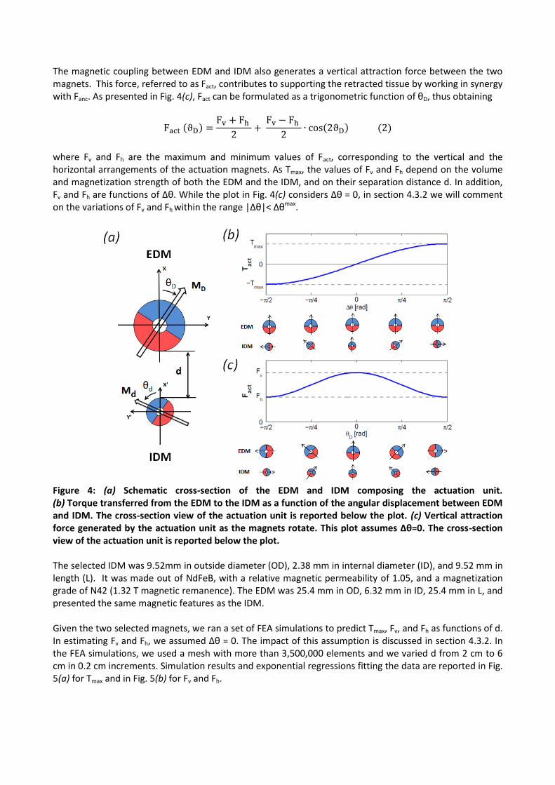
The magnetic coupling between EDM and IDM also generates a vertical attraction force between the two magnets. This force, referred to as Fact, contributes to supporting the retracted tissue by working in synergy with Fanc. As presented in Fig. 4(c), Fact can be formulated as a trigonometric function of θD, thus obtaining
where Fv and Fh are the maximum and minimum values of Fact, corresponding to the vertical and the horizontal arrangements of the actuation magnets. As Tmax, the values of Fv and Fh depend on the volume and magnetization strength of both the EDM and the IDM, and on their separation distance d. In addition, Fv and Fh are functions of Δθ. While the plot in Fig. 4(c) considers Δθ = 0, in section 4.3.2 we will comment on the variations of Fv and Fh within the range |Δθ|< Δθmax.
Figure 4: (a) Schematic cross-section of the EDM and IDM composing the actuation unit. (b) Torque transferred from the EDM to the IDM as a function of the angular displacement between EDM and IDM. The cross-section view of the actuation unit is reported below the plot. (c) Vertical attraction force generated by the actuation unit as the magnets rotate. This plot assumes Δθ=0. The cross-section view of the actuation unit is reported below the plot. The selected IDM was 9.52mm in outside diameter (OD), 2.38 mm in internal diameter (ID), and 9.52 mm in length (L). It was made out of NdFeB, with a relative magnetic permeability of 1.05, and a magnetization grade of N42 (1.32 T magnetic remanence). The EDM was 25.4 mm in OD, 6.32 mm in ID, 25.4 mm in L, and presented the same magnetic features as the IDM. Given the two selected magnets, we ran a set of FEA simulations to predict Tmax, Fv, and Fh as functions of d. In estimating Fv and Fh, we assumed Δθ = 0. The impact of this assumption is discussed in section 4.3.2. In the FEA simulations, we used a mesh with more than 3,500,000 elements and we varied d from 2 cm to 6 cm in 0.2 cm increments. Simulation results and exponential regressions fitting the data are reported in Fig. 5(a) for Tmax and in Fig. 5(b) for Fv and Fh.

Figure 5: (a) and its exponential regression at different separation distances, the solid horizontal line represents the average nominal torque for commercially available EM motors that would fit a volume similar to the IDM [26-28]. (b) and their exponential regressions at different separation distances, assuming Δθ = 0. From Fig. 5(a), it is interesting to observe that if compared to EM motors having a volume similar to the IDM [26-28], the torque available for driving a mechanism is larger as long as d remains below 5 cm. Considering that the speed ratio from the EDM to the IDM is 1:1, the overall mechanical power that can be provided to a mechanism inside the abdominal cavity mainly depends on the speed of the external motor spinning the EDM. As the size is not a primary constraint in selecting the external actuator, a fast motor that is powerful enough to spin the EDM can easily overcome the mechanical power that can be delivered by an embedded EM motor, constrained in size to fit a 12-mm surgical port.
4.2 Mechanical train design
4.2.1 Planetary Gearhead The first module of the mechanical train consists of a PG with three stages having a 1:64 gear ratio (GRpg). The annular ring (A in Fig. 6(a)) and the entire PG is 11 mm in outer diameter and 17 mm in length. For each stage, the load is transferred from the sun to the annular ring via the planets. The more the planets, the lower is the local stress at the interface between each planet and the annular ring. Therefore, to optimize the loadability of the system, we maximized the number of planets by using four of them for each stage. Suns (S in Fig. 6(a)) and planets (P in Fig. 6(a)) were designed with 10 involute profile teeth, 0.32 module, 22.5° pressure angle, 3.2 mm pitch diameter, and 3.125 mm thickness. The parts were fabricated in Aluminum 6061-T6 (tensile strength – yield 276 MPa; tensile strength - ultimate 310MPa; relative magnetic permeability 1.004) by spark erosion.
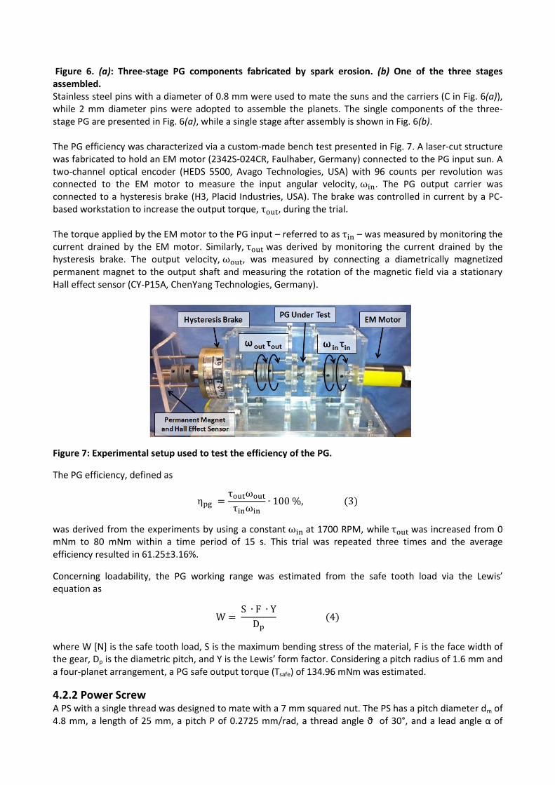
Figure 6. (a): Three-stage PG components fabricated by spark erosion. (b) One of the three stages assembled. Stainless steel pins with a diameter of 0.8 mm were used to mate the suns and the carriers (C in Fig. 6(a)), while 2 mm diameter pins were adopted to assemble the planets. The single components of the three-stage PG are presented in Fig. 6(a), while a single stage after assembly is shown in Fig. 6(b). The PG efficiency was characterized via a custom-made bench test presented in Fig. 7. A laser-cut structure was fabricated to hold an EM motor (2342S-024CR, Faulhaber, Germany) connected to the PG input sun. A two-channel optical encoder (HEDS 5500, Avago Technologies, USA) with 96 counts per revolution was connected to the EM motor to measure the input angular velocity, . The PG output carrier was connected to a hysteresis brake (H3, Placid Industries, USA). The brake was controlled in current by a PC-based workstation to increase the output torque, , during the trial. The torque applied by the EM motor to the PG input – referred to as – was measured by monitoring the current drained by the EM motor. Similarly, was derived by monitoring the current drained by the hysteresis brake. The output velocity, , was measured by connecting a diametrically magnetized permanent magnet to the output shaft and measuring the rotation of the magnetic field via a stationary Hall effect sensor (CY-P15A, ChenYang Technologies, Germany).
Figure 7: Experimental setup used to test the efficiency of the PG.
The PG efficiency, defined as
was derived from the experiments by using a constant at 1700 RPM, while was increased from 0 mNm to 80 mNm within a time period of 15 s. This trial was repeated three times and the average efficiency resulted in 61.25±3.16%.
Concerning loadability, the PG working range was estimated from the safe tooth load via the Lewis’ equation as
where W [N] is the safe tooth load, S is the maximum bending stress of the material, F is the face width of the gear, Dp is the diametric pitch, and Y is the Lewis’ form factor. Considering a pitch radius of 1.6 mm and a four-planet arrangement, a PG safe output torque (Tsafe) of 134.96 mNm was estimated.
4.2.2 Power Screw A PS with a single thread was designed to mate with a 7 mm squared nut. The PS has a pitch diameter dm of 4.8 mm, a length of 25 mm, a pitch P of 0.2725 mm/rad, a thread angle ϑ of 30°, and a lead angle α of
18.3°. The nut has a thickness of 6 mm and its motion is used to actuate the OCM. Connection between the PS and the OCM was achieved via 2 mm pins placed in the nut sides. The PS parts were fabricated in brass (tensile strength – yield 310 MPa; tensile strength - ultimate 476 MPa; magnetic permeability 1.05). The torque that must be applied to the PS for achieving a force Fnut can be estimated via the following equation
where represents the mean collar diameter, the static friction coefficient between screw and nut, the static friction coefficient at the collar surface, and is the PS transfer function between the input
torque and the output force. The collar friction was assumed negligible since we used low friction Delrin bearings. With the designed geometrical parameters and the static friction coefficient of dry brass to brass (i.e., = 0.1 [29]), resulted in 0.9117 N/mNm.
The PS efficiency was assessed with a weight lifting test. The EM motor used in the previous experiment
was rigidly connected to the PS. A weight ranging from 0.4535 kg to 4.5349 kg in 0.4535 kg increments was applied to the nut, and the torque required by the EM motor to lift the weight was measured by monitoring the supply current. For each weight, three trials were performed and the average efficiency was calculated assuming no
loss in the nut velocity (i.e., the nut velocity was estimated from the motor speed via the pitch P of the PS) by using the following equation:
The efficiency ηps resulted in 69.85 ± 5.44 %.
4.2.3 Offset Crank Mechanism The final component of the mechanical train was the OCM operating the retracting lever. The OCM link dimensions, the initial configuration, and the required motion range were identified to achieve a total angular displacement of π/2 at the crank angle γ. The retracting lever integrated in the OCM can thus generate a total vertical displacement of the retracted tissue equal to its own length. Via quasi-static analysis, assuming a slow motion of the nut and negligible inertia of the links, we defined the OCM mechanical pseudo-advantage Γ – unit of mNm/N – as the ratio between the crank mechanism output torque, τcran in Fig. 8, and the related input force acting on the slider, Fnut. Considering the schematic diagram in Fig. 8, we can express Γ as a function of γ as follows:
where the angle γ is defined zero for the initial configuration – retracting lever closed – and π/2 when the
retracting lever is fully open. Considering that - the nut horizontal displacement – is the input parameter of the 1-DoF OCM system, the angle δ can be expressed as a function of γ by solving the
following system of equations in :

Figure 8: Schematic representation of the OCM. The slider is placed with an offset ( ) with respect to
the hinge point of the crank (O). Thanks to the connecting rod ( ), the nut linear motion is converted in a crank angular displacement γ.
The length of the two links (i.e., =25 mm, =9.43 mm) and the offset of the slider with respect to the
hinge point (i.e., =4 mm) provide a π/2 angular displacement in γ for a 12.7 mm motion of the slider. The mechanical pseudo-advantage Γ as the lever angle γ varies – obtained via iterative computation by assuming negligible inertia and a quasi-static regime – is presented in Fig. 9, together with its 3rd order polynomial regression (R2=0.990).
Figure 9: Mechanical pseudo-advantage Γ [mNm/N] of the OCM and its polynomial regression as a function of the lever angle γ [rad]. A maximum value of 9.63 mNm/N is obtained for γ = 2π/17, while a 4.67 mNm/N minimum occurs for the fully-open configuration (i.e., γ = π/2). The OCM parts were fabricated in aluminum 6061-T1 (tensile strength – yield 55 MPa; tensile strength - ultimate 120 MPa; magnetic permeability 1.004) via traditional machining. Stainless steel pins of 1 mm and 1.5 mm diameter were used for mating the parts.
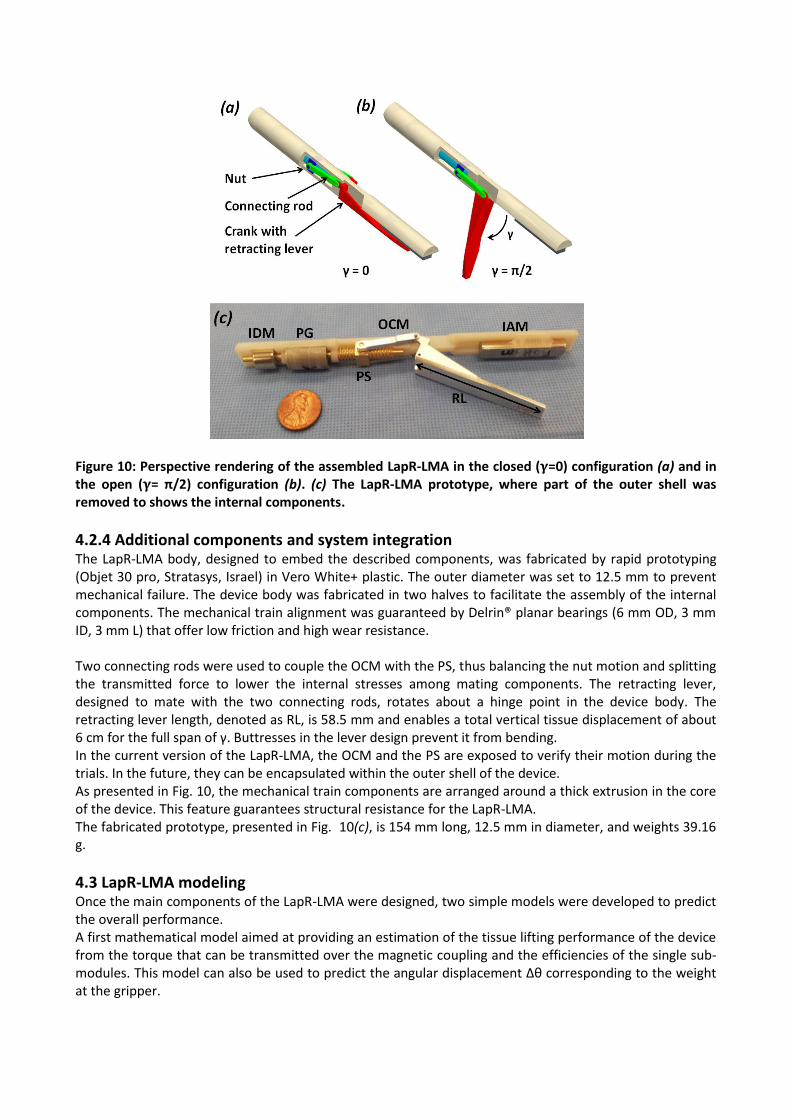
Figure 10: Perspective rendering of the assembled LapR-LMA in the closed ( =0) configuration (a) and in the open ( = π/2) configuration (b). (c) The LapR-LMA prototype, where part of the outer shell was removed to shows the internal components.
4.2.4 Additional components and system integration The LapR-LMA body, designed to embed the described components, was fabricated by rapid prototyping (Objet 30 pro, Stratasys, Israel) in Vero White+ plastic. The outer diameter was set to 12.5 mm to prevent mechanical failure. The device body was fabricated in two halves to facilitate the assembly of the internal components. The mechanical train alignment was guaranteed by Delrin® planar bearings (6 mm OD, 3 mm ID, 3 mm L) that offer low friction and high wear resistance. Two connecting rods were used to couple the OCM with the PS, thus balancing the nut motion and splitting the transmitted force to lower the internal stresses among mating components. The retracting lever, designed to mate with the two connecting rods, rotates about a hinge point in the device body. The retracting lever length, denoted as RL, is 58.5 mm and enables a total vertical tissue displacement of about 6 cm for the full span of γ. Buttresses in the lever design prevent it from bending. In the current version of the LapR-LMA, the OCM and the PS are exposed to verify their motion during the trials. In the future, they can be encapsulated within the outer shell of the device. As presented in Fig. 10, the mechanical train components are arranged around a thick extrusion in the core of the device. This feature guarantees structural resistance for the LapR-LMA. The fabricated prototype, presented in Fig. 10(c), is 154 mm long, 12.5 mm in diameter, and weights 39.16 g.
4.3 LapR-LMA modeling Once the main components of the LapR-LMA were designed, two simple models were developed to predict the overall performance. A first mathematical model aimed at providing an estimation of the tissue lifting performance of the device from the torque that can be transmitted over the magnetic coupling and the efficiencies of the single sub-modules. This model can also be used to predict the angular displacement Δθ corresponding to the weight at the gripper.

The second model we developed was a free body diagram of the LapR-LMA. This can be used to predict how much weight can be statically supported by the magnetic attraction force provided by both the anchoring unit and the actuation unit.
4.3.1 Tissue lifting model Assuming no power losses due to internal friction, the weight WL [g] that can be lifted up as the rotation of the EDM is activated can be predicted as follows:
Figure 11: Maximum weight that can be lifted by operating the LapR-LMA (dashed line), and maximum
weight that can be statically supported by the LapR-LMA (solid line). Both weight limitations are plotted
as functions of the intermagnetic distance and the opening angle of the retracting lever. The
measurements obtained during benchtop experiments are presented as single data points.
As represented by dashed blue lines in Fig. 11, WL is constant with d, as long as Tact exceeds the safe tooth-loading regime of the PG (Eq. 4). In this working regime – which covers the entire range of d from 2 cm to 4 cm specified in section 2 – the overall efficiency of the mechanical train is 42.78%. In most of this region, the angular displacement Δθ stays below π/18 (i.e., 10°), therefore we can assume Δθmax= π/18. It is also worth mentioning that WL and the mechanical train efficiency increase as γ goes from π/2 to zero thanks to the OCM contribution presented in Fig. 9. This is an advantage in doing controlled retraction, as the portion the tissue (and its weight) increases as this is being lifted.
4.3.2 Tissue supporting model To predict the weight that can be statically supported by the LapR-LMA at different d and γ, we studied the free-body diagram of the device that is presented in Fig. 12. The model considers Fanc as described in section 4.1.1, the weight force acting on the LapR-LMA, denoted with Flap, and the force FW required to lift the weight WL at the gripper. The model also considers Fact as described in section 4.1.2, but scaled for Δθmax= π/18. In case of |Δθ|< π/18, we estimated via FEA simulation a variation of Fh and Fv below 2.7% of the values reported in Fig. 5(b). In our structural model, the device body was assumed as a beam in which the magnetic forces, acting on the IAM and the IDM, are responsible for anchoring the LapR-LMA against the abdominal wall (here assumed as a rigid constraint). The force Fw was assumed to act downward on a point whose position depends on the angular coordinate of the lever γ. As presented in Fig. 12(a), the LapR-LMA is designed so

that Fw is always applied to a position in between the points of application of Fanc and Fact (B and D in Fig. 12(b)), thus improving the stability during controlled retraction.
Figure 12: Structural model used to predict the weight that the LapR-LMA can statically support. (a) Cross-section of the LapR-LMA with the points of application of the different forces. (b) Free body diagram of the LapR-LMA. A is the extremity of the device at the side of the IAM, B is the point of application of Fanc, C is the point where the hinge of the lever is located, D is the point of application of Fact, X is the LapR-LMA center of mass. Since Fanc is larger than Fact for any d – as presented in Fig. 3 and Fig. 5(b) – anchoring failure would most likely occur with the LapR-LMA pivoting about the edge next to the IAM (i.e., point A in Fig. 12(b)). In particular, the worst-case scenario occurs for γ=π/2, as Fw is applied at the lever hinge point (i.e., C in Fig. 12(b)) and its moment arm around A is maximized. The condition for a stable anchoring can then be expressed by considering the rotational equilibrium in A, as
where Flap is the force required to lift the LapR-LMA and X is the position of the LapR-LMA center of mass. This stability condition is plotted with solid black lines in Fig. 11, showing the maximum weight WL that can be statically supported by the LapR-LMA as a function of d and γ. Also in this case, the performance improves as γ goes from π/2 to 0, since the point of application of FW moves closer to the pivoting point (i.e., A in Fig. 12(b)). By plotting together the tissue lifting and the tissue support models, as in Fig. 11, we can derive the operative range for the LapR-LMA as the area below the minimum value of WL that can be supported and lifted at the same time. Considering the geometrical features of the LapR-LMA and the values of the anchoring forces within the operative range, the pressure exerted by the device on the abdominal wall always stays below 30.7 kPa, thus satisfying the condition on safety specified in section 2.
4.4 External Controller The external controller was designed to host the EDM, the EAM and the EM motor (2342S-024CR, Faulhaber, Germany) in a plastic handle. A shape with five cavities – where the operator can insert his/her own fingers – was obtained by laser-cutting and assembling Plexiglas sheets.

As presented in Fig. 13, the EDM was rigidly connected to the EM motor via a shaft coupler. Bearings were used to support the shaft. Spacing between the EDM and the EAM mirrored the positioning of the IDM and the IAM inside the LapR-LMA. A two-state switch was connected to the motor controller to change the direction of rotation for the EDM. This enabled switching between lifting up and lowering down the tissue connected to the grasper. An adjustable clutch arm – not presented in Fig. 13 – can be connected to the controller to hold it in place during the surgical procedure.
Figure 13: Perspective rendering of the external controller.
5 EXPERIMENTAL ASSESSMENT
A three-tier validation approach was adopted to assess the LapR-LMA performance. First, a benchtop experiment was performed to verify the weight that the device can controllably lift and hold at different intermagnetic separation distances. Then, an ex vivo experiment, using freshly excised porcine tissues, was performed to investigate the feasibility of using the LapR-LMA for liver retraction. Finally, the same procedure was performed laparoscopically in a porcine model to assess the usability and the safety of the device.
5.1 Benchtop Experiments
The main goal of this experiment was to confirm the operative range of the LapR-LMA as estimated in
section 4.3. As presented in Fig. 14, the external controller was affixed to a vertical adjustable slider and
coupled with the LapR-LMA through a rigid plastic surface. The weight was connected to the lever – starting
at γ=π/2 – via an inextensible wire. Then, the external EM motor was activated with a step command at a
speed of 1,700 rpm. The direction of rotation was reversed when γ reached zero, and the lever was moved
back to its starting position. The maximum value of weight that was successfully lifted up and lowered
down was recorded for each trial. This test was performed three times for each intermagnetic distance
ranging from 2 cm to 4 cm, with 0.5 cm increments, and the results are presented in Fig. 11.

Figure 14: Experimental setup during the benchtop experiments.
The trial performed at d=2cm lifting a weight of 500 g is presented in Fig. 15. The overall result of this
experiment showed that the model in Fig. 11 always overestimated WL with an error of 9.06 ± 0.52%. This
may be due to the cross-talking effect between the anchoring module and the actuation module, which
was neglected while modeling the LapR-LMA.
During the experiments, failure always occurred for γ=π/2, with the device losing the magnetic coupling
with the external controller (i.e., failure in anchoring). The actuation module always performed correctly,
never entering the pole-slipping regime. This confirmed the assumption of a small Δθmax. The average time
to conclude a single trial was 41.65 ± 2.11 s. Finally, the benchtop experiment confirmed that the designed
mechanism is not backdrivable, as the lever was able to maintain its position for γ=0.
Figure 15: Sequence showing a single trial with a weight of 500g at d=2 cm. Lifting up the weight required
21 s, as indicated by the stopwatch in the lower right corner.
5.2 Ex vivo trials
A typical task for a surgical retractor is to lift up the liver and hold it in position. The gallbladder and the
stomach lie underneath it. To expose them and to achieve an adequate visibility of the surgical workspace,
the surgeon usually has to lift the right lobe of the liver. This procedure was simulated with the same setup
described in section 5.1, using a freshly excised porcine liver (672 g) instead of the weight. The liver was

placed 15 cm away from the plastic surface. A crocodile grasper – connected to the LapR-LMA lever via an
inextensible wire – was secured to a lobe of the liver. Retraction was performed starting from γ=π/2 for
d=2cm (Fig. 16(a)) and d=4cm (Fig. 16(b)). The EM motor was driven at 1,700 rpm. Three trials were
performed for each distance and the liver was always lifted up and lowered down successfully. From the
frames in Fig. 16, it is possible to appreciate how the portion of suspended tissue increases during
retraction. As previously discussed, this is compensated by the increase in lifting and supporting capacity
for the LapR-LMA as γ decreases from π/2 to zero.
Figure 16: Ex vivo liver retraction using the LapR-LMA. In the sequence presented in (a), the
intermagnetic distance is 2 cm, while in the sequence in (b) is 4 cm.
5.3 In vivo trials
The primary goal of the in vivo trials was to qualitatively assess the functionality, the usability, and the
safety of the LapR-LMA on an anesthetized porcine model. In particular, having a compliant tissue in
between the external controller and the LapR-LMA allows the retractor to vibrate in the vertical direction
under the effect of the varying Fact. This vertical wobbling may affect the lifting and the anchoring capacity,
whereas the magnetic pinching may pose a safety risk to the tissue in between the external controller and
the LapR-LMA.
The surgical procedure was performed at Vanderbilt University, with the assistance and collaboration of a
specially trained medical team (IACUC Approval number M13003), in accordance with all ethical
considerations and the regulations related to animal experiments. A 55-kg female Yorkshire swine was used
for this study. After intravenous sedation, minimally invasive access was gained by one 5-mm trocar (5
Versaport Plus, Covidien, Norwalk, CT, USA) and one 12-mm trocars (5-12Versaport Plus, Covidien,
Norwalk, CT,USA). The LapR-LMA was introduced in the abdominal cavity and coupled with the external
controller. An abdominal thickness of 2 cm was measured by the surgeon at the insertion point, before the
placement of the port. Then, a pneumoperitoneum was achieved with carbon dioxide gas.
Under endoscopic vision, the external controller was manually operated to drag the LapR-LMA next to the
liver. The surgeon used a standard laparoscopic grasper to attach the crocodile jaws to one lobe of the

liver. Retraction was then activated by rotating the driving magnet until the tissues below the liver were
exposed, as shown in Fig. 17. This procedure was repeated five times, always changing the position of the
LapR-LMA and the point at which the liver was grasped. The animal was sacrificed at the end of the
procedure. The region of abdominal tissue at which the LapR-LMA was anchored during retraction was then
explanted and examined by an expert pathologist, reporting no sign of tissue damage due to magnetic
pinching.
While the retraction was always successful and the LapR-LMA never lost the magnetic coupling with the
external controller, the length of the device sometimes hampered the mobility inside the abdominal cavity.
This limited the positioning of the LapR-LMA by only a few degrees off the sagittal plane of the animal.
Placing the LapR-LMA along the transverse direction was not possible. This limited the reachable workspace
and the possible approaching angles to the tissue to be retracted.
Figure 17: LapR-LMA performing liver retraction during the in vivo trials.
6 CONCLUSION AND FUTURE DEVELOPMENTS
Magnetic fields can be harnessed to transfer controllable mechanical power from outside the patient’s
body to a laparoscopic instrument within the body. Combining magnetic units with different functions, i.e.
anchoring or actuation, it is possible to design surgical robots that do not require motors on board, nor take
up port space during the procedure.
Given the constraints in diameter and volume of a MIS instrument, the proposed approach enables the
transfer of a larger amount of mechanical power than what is possible to achieve by embedding typical
electromechanical actuators on board. At the same time, due to magnetic coupling, triangulation is
enhanced and invasiveness is reduced.
In this study, we demonstrated the feasibility of using the LMA approach to design a tetherless laparoscopic
tissue retractor. The same design steps (i.e., medical consideration and technical requirements related to
magnetic coupling, magnetic modeling, selection of the magnets, interfacing between the IDM and the
mechanical train, and modeling of the overall device performance) can be adopted to implement LMA-
based surgical robots performing different and more complex tasks.
The LapR-LMA is 12.5 mm in diameter and can be introduced laparoscopically. If the abdominal wall
thickness is about 2 cm, the LapR-LMA is able to retract more than ten times its own weight. Bench trials
demonstrated that the designed mechanism is not backdrivable and guarantees accurate and controllable
motion of the retraction lever in both directions. The mechanism is able to cover the full range of motion in
about 20 s. While the motion is slower if compared with manual operation of a laparoscopic retractor, the
surgeon has the ability to adjust precisely the degree of retraction achieved by the LapR-LMA. Should a
shorter time be required, the motor in the external controller can be replaced with a faster one.

In situations of overload, failure occurs in anchoring rather than actuation. If the anchoring failure occurs,
the LapR-LMA needs to be recoupled with the external controller by the surgeon during the procedure.
However, no failure was observed during the liver retraction experiment that was performed on a porcine
model presenting an abdominal tissue thickness of 2 cm. The same experiment showed no abdominal wall
tissue damage due to magnetic pinching.
While this study showed promising results, a number of challenges remain for future research.
Regarding LapR-LMA modeling, the maximum weight that can be lifted was overestimated by about 9%.
This was mainly due to the assumption of no cross-coupling between the anchoring and the actuation units.
Therefore, a more comprehensive model, capturing the interactions among all the magnets in the device,
must be developed. The closer the anchoring and the actuation units, the stronger the cross-coupling
between them, thus, a better model will be crucial for designing a shorter version of the LapR-LMA.
Reducing the length of the device would improve maneuverability and provide better access to the surgical
target, as observed during the in vivo trials.
As the main goal of this study was to assess the mechanical power transfer that can be achieved via the
LMA approach, we did not focus extensively on the part of the device interacting with the tissue to be
retracted. In particular, liver retraction was performed with traumatic graspers because of their availability.
This is not applicable to a clinical case, where suction cups [19] or a fan-shaped end effector [3] must be
used instead to prevent damaging the hepatic tissue. The current version of the LapR-LMA can be used
whenever the retracted tissue must be removed at the end of the surgical procedure (e.g.,
cholecystectomy). While the current device is wireless, a thin tethered connection can be introduced to
facilitate retrieval at the end of the procedure. Future studies involving surgeons will be devoted to assess
and to improve, if needed, the usability and the ergonomics of the device.
The permanent magnets that were embedded in the LapR-LMA maintain their magnetic properties up to
80°C. If autoclave sterilization is needed, they must be replaced with more expensive magnets – still
available from the same supplier – that can withstand a temperature up to 150°C. An alternative is to
conceive the LapR-LMA as a single-use disposable device. If the mechanical parts are mass fabricated, the
overall cost of the device may fall to a few dollars.
Concerning the fabrication material, the LapR-LMA body was obtained by rapid prototyping using Vero
White+ plastic. Moving forward to clinical trials, a biocompatible material must be used. Either computer
numerical control machining or injection molding can be adopted to fabricate the body as part of a
reusable or disposable instrument, respectively.
Stronger retraction forces at larger distances can be obtained by using external permanent magnets with
higher magnetization grades or larger volumes. The proposed modeling methods can be used to select the
appropriate magnets to fit specific requirements, possibly extending the reach of this approach to obese
patients.
Finally, an intriguing direction of future research is to design an LMA-based surgical robot with multiple
DoFs. Such a device would be able to achieve complex surgical tasks, such as surface scanning with an
optical probe or even suturing. Combining a number of actuation units and one or more anchoring units in
a device that can fit a laparoscopic access requires advanced modeling and, most likely, the use of shielding
material [30] between units.
REFERENCES
[1] Park, S., Bergs, R. A., Eberhart, R., Baker, L., Fernandez, R., & Cadeddu, J. A. (2007). Trocar-less
instrumentation for laparoscopy: magnetic positioning of intra-abdominal camera and retractor. Annals of
Surgery, 245(3), 379.
[2] Best, S. L., Kabbani, W., Scott, D. J., Bergs, R., Beardsley, H., Fernandez, R., & Cadeddu, J. A. (2011).
Magnetic anchoring and guidance system instrumentation for laparo-endoscopic single-site surgery/natural
orifice transluminal endoscopic surgery: lack of histologic damage after prolonged magnetic coupling across
the abdominal wall. Urology, 77(1), 243-247.
[3] Park, S., Bergs, R. A., Eberhart, R., Baker, L., Fernandez, R., & Cadeddu, J. A. (2007). Trocar-less
instrumentation for laparoscopy: magnetic positioning of intra-abdominal camera and retractor. Annals of
Surgery, 245(3), 379-384.
[4] Padilla, B. E., Dominguez, G., Millan, C., & Martinez-Ferro, M. (2011, November). The use of magnets
with single-site umbilical laparoscopic surgery. In Seminars in Pediatric Surgery, Vol. 20, No. 4, pp. 224-231.
[5] Zeltser, I. S., Bergs, R., Fernandez, R., Baker, L., Eberhart, R., & Cadeddu, J. A. (2007). Single trocar
laparoscopic nephrectomy using magnetic anchoring and guidance system in the porcine model. The Journal
of Urology, 178(1), 288-291.
[6] Cadeddu, J., Fernandez, R., Desai, M., Bergs, R., Tracy, C., Tang, S. J., & Scott, D. (2009). Novel
magnetically guided intra-abdominal camera to facilitate laparoendoscopic single-site surgery: initial
human experience. Surgical Endoscopy, 23(8), 1894-1899.
[7] Lehman, A. C., Dumpert, J., Wood, N. A., Redden, L., Visty, A. Q., Farritor, S., & Oleynikov, D. (2009).
Natural orifice cholecystectomy using a miniature robot. Surgical Endoscopy, 23(2), 260-266.
[8] Tortora, G., Dario, P., & Menciassi, A. (2014). Array of robots augmenting the kinematics of endocavitary
surgery. Mechatronics, IEEE/ASME Transaction on, in press, available on-line.
[9] Simi, M., Silvestri, M., Cavallotti, C., Vatteroni, M., Valdastri, P., Menciassi, A., & Dario, P. (2013).
Magnetically Activated Stereoscopic Vision System for Laparoendoscopic Single-Site Surgery. Mechatronics,
IEEE/ASME Transactions on, 18(3), 1140-1151.
[10] Vartholomeos, P., Bergeles, C., Qin, L., & Dupont, P. E. (2013). An MRI-powered and controlled actuator
technology for tetherless robotic interventions. The International Journal of Robotics Research, 32(13),
1536-1552.
[11] Heller, J. A., Kwiat, D., Fechter, R., Harrison, M. R., Roy, S., Liu, J. A., & Etemadi, M. (2012).
ROBOImplant II: Development of a Noninvasive Controller/Actuator for Wireless Correction of Orthopedic
Structural Deformities. Journal of Medical Devices, 6(3), 031006.
[12] Di Natali, C., Ranzani, T., Simi, M., Menciassi, A., & Valdastri, P. (2012, May). Trans-abdominal Active
Magnetic Linkage for robotic surgery: Concept definition and model assessment. In Robotics and
Automation (ICRA), 2012 IEEE International Conference on, pp. 695-700.
[13] Di Natali, C. and Valdastri, P. (2012). Remote active magnetic actuation for a single-access surgical robotic manipulator. International Journal of Computer Assisted Radiology and Surgery, 7:S169-S171. [14] Best, S. L., Bergs, R., Gedeon, M., Paramo, J., Fernandez, R., Cadeddu, J. A., & Scott, D. J. (2011).
Maximizing coupling strength of magnetically anchored surgical instruments: how thick can we go? Surgical
Endoscopy, 25(1), 153-159.
[15] Steris Corporation, 1994, “AMSCO Evolution Floor Loader”, Steam sterilizer,
http://www.steris.com/products/steam-sterilizer/amsco-evolution-floor-loader (accessed June 27, 2014)

[16] Beckerman, P. and Ma, J. (2006 February). A Compact, Modular, Teleoperated Robotic Minimally Invasive Surgery System. in Proc. First IEEE/RAS-EMBS Int. Conf. Biomed. Robot. Biomechatron. (BioRob 2006), pp. 702–707
[17] Ryou, M., & Thompson, C. C. (2009). Magnetic retraction in natural-orifice transluminal endoscopic
surgery (NOTES): addressing the problem of traction and countertraction. Endoscopy, 41(02), 143-148.
[18] Canes, D., Lehman, A. C., Farritor, S. M., Oleynikov, D., & Desai, M. M. (2009). The future of NOTES
instrumentation: flexible robotics and in vivo minirobots. Journal of Endourology, 23(5), 787-792.
[19] Gan, P. (2014). A novel liver retractor for reduced or single-port laparoscopic surgery. Surgical
Endoscopy, 28(1), 331-335.
[20] Furlani, E. P. (2001). Permanent magnet and electromechanical devices: materials, analysis, and
applications. Academic Press.
[21] Agashe, J. S., & Arnold, D. P. (2008). A study of scaling and geometry effects on the forces between
cuboidal and cylindrical magnets using analytical force solutions. Journal of Physics D: Applied
Physics, 41(10), 105001.
[22] Ikuta, K., Makita, S., & Arimoto, S. (1991, September). Non-contact magnetic gear for micro
transmission mechanism. In Micro Electro Mechanical Systems, 1991, IEEE MEMS'91, Proceedings, pp. 125-
130.
[23] Simi, M., Gerboni, G., Menciassi, A., & Valdastri, P. (2013). Magnetic torsion spring mechanism for a
wireless biopsy capsule. Journal of Medical Devices, 7(4), 041009.
[24] Sudano, A., Accoto, D., Zollo, L., & Guglielmelli, E. (2013). Design, Development and Scaling Analysis of
a Variable Stiffness Magnetic Torsion Spring, International Journal of Advanced Robotic Systems, 2013,
10:372.
[25] Montague, R., Bingham, C., & Atallah, K. (2012). Servo control of magnetic gears. Mechatronics,
IEEE/ASME Transactions on, 17(2), 269-278.
[26] Namiki precision jewel CO, 1999, “φ 10 mm”, DC micromotors,
http://www.namiki.net/product/dcmotor/coreless.html (accessed June 26, 2014)
[27] Faulhaber miniature drive system, 1997, “φ 10 mm”, DC micromotors,
http://www.fmcc.faulhaber.com/type/PGR_13813_13801/PGR_13818_13813/en/. (accessed June 26,
2014)
[28] DC motors and drive system by Maxon Motor, 2011, “φ 10 mm & Torque 2-5 mNm”, Maxon DC Motor
Catalogu, “http://www.maxonmotor.com/maxon/view/catalog (accessed June 26, 2014)
[29] Chowdhury, A. M., Nuruzzaman, D. M., Mia, A. H., & Rahaman, M. L. (2012). Friction coefficient of
different material pairs under different normal loads and sliding velocities. Tribology in Industry, 34(1), 18-
23.

[30] Brewer, R. D., Loewke, K. E., Duval, E. F., & Salisbury, J. K. (2008, October). Force control of a permanent
magnet for minimally-invasive procedures. In Biomedical Robotics and Biomechatronics, 2008. BioRob 2008.
2nd IEEE RAS & EMBS International Conference on, pp. 580-586.