Language: sx/US Issue no: DMC: BD500-A-J53-82-55-04AAA ...
12
See applicability on the first page of the DM BD500-A-J53-82-55-04AAA-720A-A BD500-A-J53-82-55-04AAA-720A-A 2020-06-26 Page 1 Aft fairing strut, Wing To Body Fairing (WTBF) - Install procedure DMC: BD500-A-J53-82-55-04AAA-720A-A Language: sx/US Issue no: 006 Issue Date: 2020/06/26 Title: Aft fairing strut, Wing To Body Fairing (WTBF) - Install procedure Security classification: Class01 Responsible partner company: Bombardier/ 3AB48 Originator: Bombardier/ 3AB48 Applicability: 50006-50065, 55003-55143 Brex data module reference: Quality assurance status: First verification: Table top Reason for updating: To revise the procedure.
Transcript of Language: sx/US Issue no: DMC: BD500-A-J53-82-55-04AAA ...

See applicability on thefirst page of the DMBD500-A-J53-82-55-04AAA-720A-A
BD500-A-J53-82-55-04AAA-720A-A
2020-06-26 Page 1
Aft fairing strut, Wing To Body Fairing (WTBF) - Install procedure
DMC: BD500-A-J53-82-55-04AAA-720A-A
Language: sx/US
Issue no: 006
Issue Date: 2020/06/26
Title: Aft fairing strut, Wing To Body Fairing (WTBF) - Install procedure
Security classification: Class01
Responsible partnercompany:
Bombardier/ 3AB48
Originator: Bombardier/ 3AB48
Applicability: 50006-50065, 55003-55143
Brex data modulereference:
Quality assurancestatus:
First verification: Table top
Reason for updating: To revise the procedure.

Intentionally left blank
See applicability on thefirst page of the DMBD500-A-J53-82-55-04AAA-720A-A
BD500-A-J53-82-55-04AAA-720A-A
2020-06-26 Page 2

See applicability on the first page of the DMBD500-A-J53-82-55-04AAA-720A-A
BD500-A-J53-82-55-04AAA-720A-A
2020-06-26 Page 3
Aft fairing strut, Wing To Body Fairing (WTBF) - Install procedure
References
Table 1 References
Data Module/Technical Publication Title
BD500-A-J20-20-01-00AAA-720A-A Lockwire - Install procedure
BD500-A-J20-20-03-00AAA-720A-A Safety cable - Install procedure
BD500-A-J20-31-00-00AAA-711A-A Torquing of threaded fasteners - Tighten procedure
BD500-A-J51-21-11-04AAA-259A-A Corrosion inhibiting jointing compound - Corrosionprevention procedures
BD500-A-J51-26-00-01AAA-251A-A Solvent cleaning - Clean with chemical agent
Common information
This data module gives the procedure to install the aft fairing strut (written as "strut" in thisprocedure). The struts are installed on the aft Wing To Body Fairing (WTBF).
Preliminary requirements
Production maintenance data
Zones 195 Aft wing to fuselage fairing,left side
Zones 196 Aft wing to fuselage fairing,right side
Access points 195GB Panel
Access points 195HB Panel
Access points 195JB Panel
Access points 196HB Panel
Access points 196JB Panel
Required conditions
Table 2 Required conditions
Action/Condition Data Module/Technical publication
Make sure that the aircraft is in the sameconfiguration as in the remove data module.
Obey the torquing of threaded fastenersstandard practices.
BD500-A-J20-31-00-00AAA-711A-A

See applicability on the first page of the DMBD500-A-J53-82-55-04AAA-720A-A
BD500-A-J53-82-55-04AAA-720A-A
2020-06-26 Page 4
Action/Condition Data Module/Technical publication
Obey the Corrosion Inhibiting JointingCompound standard practices.
BD500-A-J51-21-11-04AAA-259A-A
Obey the solvent cleaning standardpractices.
BD500-A-J51-26-00-01AAA-251A-A
Obey the lock wire install procedure. BD500-A-J20-20-01-00AAA-720A-A
Obey the safety cable install procedure. BD500-A-J20-20-03-00AAA-720A-A
Support equipment
Table 3 Support equipment
Name Identification/Reference Quantity Remark
None
Consumables, materials, and expendables
Table 4 Consumables, materials, and expendables
Name Identification/Reference Quantity Remark
Grease, aircraft andinstrument, gear andactuator screw
04-017 AR
Lockwire, cres 0.032 in.(0.813 mm) diameter
05-004 AR
Cable safety and ferrulekit, 0.032-0.038 in.(0.81-0.97 mm) nominaldiameter, 18.0 in.(457.2 mm) length,corrosion and heatresistant steel
05-504 AR
Ink marking 05-814 AR
Non-chromate, corrosioninhibiting jointingcompound
15-035 AR

See applicability on the first page of the DMBD500-A-J53-82-55-04AAA-720A-A
BD500-A-J53-82-55-04AAA-720A-A
2020-06-26 Page 5
Spares
Table 5 Spares
Name Identification/Reference Quantity Remark
Aft fairing strut, WTBF CSN 53-82-55-04AAA001 1
Safety conditions
None
Procedure1 Install the strut (1), (2), (3), (4), (5), or (6) as follows:
Refer to Fig. 1.1.1 Make sure that the mating surfaces are clean and there is no contamination
from paint, grease, or preservative fluids.
1.2 Install the strut (5) or (6) as follows:1.2.1 Put the strut (5) or (6) in position.
1.2.2 Apply the Corrosion Inhibiting Compound (CIC) (15-035) on the flatwasher (9).
1.2.3 Apply the grease (04-017) on the bushing (12) and bolt (28).
1.2.4 Install the bushing (12), countersunk washer (11), bolt (28), flat washer(9), and nut (8).
1.2.5 Apply the CIC (15-035) on the flat washer (9).
1.2.6 Apply the grease (04-017) on the bushing (17) or (30) and the bolt(14) or (29).
1.2.7 Install the bushing (17) or (30), countersunk washer (11), bolt (14) or(29), flat washer (9), and nut (13).
1.2.8 Safety the nuts (8) and (13) with the cotter pins (7).
1.3 Install the strut (4) as follows:1.3.1 Put the strut (4) in position.
1.3.2 Apply the CIC (15-035) on the flat washer (21).
1.3.3 Apply the grease (04-017) on the bushing (24) and bolt (22).
1.3.4 Install the bushing (24), countersunk washer (23), bolt (22), flat washer(21), and nut (20).
1.3.5 Apply the CIC (15-035) on the flat washer (21).
1.3.6 Apply the grease (04-017) on the bushing (27) and the bolt (26).
1.3.7 Install the bushing (27), countersunk washer (23), bolt (26), flat washer(21), and nut (25).

See applicability on the first page of the DMBD500-A-J53-82-55-04AAA-720A-A
BD500-A-J53-82-55-04AAA-720A-A
2020-06-26 Page 6
1.3.8 Safety the nut (25) with the cotter pin (19).
1.3.9 On the right and left side of detail view G, adjust the load on the tierod of the support structure of the WTBF as follows:1.3.9.1 With an indelible ink pen (05-814), make a mark to index
the tube body and the fork end of the tie rod at FS973.0,just outboard of LBL40.0 (left side) and RBL40.0 (rightside).
1.3.9.2 Remove the nut (20), washers (21) (23), bushing (24) andbolt (22) that attaches the lower end of the tie rod to thesupport structure.
1.3.9.3 Remove and discard the safety cable (05-504) or lock wire(05-004) form the tie rod jam nut.
1.3.9.4 Loosen the jam nut sufficiently to allow the tube body toturn.
1.3.9.5 Apply the CIC (15-035) on the flat washer (21).
1.3.9.6 Apply the grease (04-017) on the bushing (24) and the bolt(22).
1.3.9.7 Turn the tube body clock wise or counter clock wisesufficiently to install the bolt (22), the washer (23), and thebushing (24), and the bolt (22) is free to turn.
NoteThe amount of rotation of the tube body is +/- 1/8 of aturn.
1.3.9.8 Install the washer (21) and nut (20).
1.3.9.9 Turn the tube body clock wise or counter clock wisesufficiently so that the bolt (22) is no longer free to turn.
1.3.9.10 Torque the nut (20) to 160 - 190 lbf in. (18.08 - 21.47Nm).
1.3.9.11 Install the cotter pin (19).
1.3.9.12 Torque the jam nut to 53 - 80 lbf in. (5.99 - 9.04 Nm).
1.3.9.13 Safety the jam nut and locking device with lock wire
1.3.9.14 Make sure that no threads of the inserts are visible fromeither ends.
1.3.9.15 If threads of the inserts are visible, do as follows:1.3.9.15.1 Remove and discard the tie rod.
1.3.9.15.2 Install a new tie rod.
NoteAdjust the load on the new tie rod asdescribed in the previous steps.
1.4 Install the strut (3) as follows:1.4.1 Put the strut (3) in position.
See applicability on the first page of the DMBD500-A-J53-82-55-04AAA-720A-A
BD500-A-J53-82-55-04AAA-720A-A
2020-06-26 Page 7
1.4.2 Apply the CIC (15-035) on the flat washer (9).
1.4.3 Apply the grease (04-017) on the bushing (12) and bolt (10).
1.4.4 Install the bushing (12), countersunk washer (11), bolt (10), flat washer(9), and nut (8).
1.4.5 Apply the CIC (15-035) on the flat washer (9).
1.4.6 Apply the grease (04-017) on the bushing (17) or (18) and the bolt(14) or (16).
1.4.7 Install the bushing (17) or (18), countersunk washer (11), bolt (14) or(16), flat washer (9), and nut (13).
1.4.8 Safety the nuts (8) and (13) with the cotter pins (7).
1.5 Install the strut (1) or (2) as follows:1.5.1 Put the strut (1) or (2) in position.
1.5.2 Apply the CIC (15-035) on the flat washer (9).
1.5.3 Apply the grease (04-017) on the bushing (12) and bolt (10).
1.5.4 Install the bushing (12), countersunk washer (11), bolt (10), flat washer(9), and nut (8).
1.5.5 Torque the nut (8) to 79.60 lbf-in (9.00 Nm).
1.5.6 Apply the CIC (15-035) on the flat washer (9).
1.5.7 Apply the grease (04-017) on the bushing (15) and the bolt (14).
1.5.8 Install the bushing (15), countersunk washer (11), bolt (14), flat washer(9), and nut (13).
1.5.9 Torque the nut (13) to 79.60 lbf-in (9.00 Nm).
1.5.10 Safety the nuts (8) and (13) with the safety cable (05-504).
NoteYou can use the lockwire (05-004) as an alternative to the safetycable (05-504).

See applicability on the first page of the DMBD500-A-J53-82-55-04AAA-720A-A
BD500-A-J53-82-55-04AAA-720A-A
2020-06-26 Page 8
FR54
FR56
6
14
12
13
7
9
1711
8
9
11
28
7
28
8
7
9
12
1113
7
9
1129
6
30
ICN-BD500-A-J538255-C-3AB48-28534-A-001-01Fig. 1 Aft fairing strut, Wing To Body Fairing (WTBF) - Remove/Install
- (Sheet 1 of 4)
See applicability on the first page of the DMBD500-A-J53-82-55-04AAA-720A-A
BD500-A-J53-82-55-04AAA-720A-A
2020-06-26 Page 9
14
9
7
8
9
1011
12
10
1112
9
8
9
287
9
5
11
12
7
1317
11
3
1811
16
7
13
8
7
1711
14
97
133
7
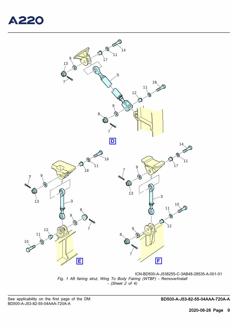
ICN-BD500-A-J538255-C-3AB48-28535-A-001-01Fig. 1 Aft fairing strut, Wing To Body Fairing (WTBF) - Remove/Install
- (Sheet 2 of 4)

See applicability on the first page of the DMBD500-A-J53-82-55-04AAA-720A-A
BD500-A-J53-82-55-04AAA-720A-A
2020-06-26 Page 10
2723
9
20
2921
4
11
8
7
28
12
22
23
24
19
25
21
26
19
5
3011
913
7
ICN-BD500-A-J538255-C-3AB48-28536-A-001-01Fig. 1 Aft fairing strut, Wing To Body Fairing (WTBF) - Remove/Install
- (Sheet 3 of 4)

See applicability on the first page of the DMBD500-A-J53-82-55-04AAA-720A-A
BD500-A-J53-82-55-04AAA-720A-A
2020-06-26 Page 11
9
15
14
14
12
10
11
11 12
8
98
15119
13
7 1
710
2
11
9
7
13
7
ICN-BD500-A-J538255-C-3AB48-28537-A-001-01Fig. 1 Aft fairing strut, Wing To Body Fairing (WTBF) - Remove/Install
- (Sheet 4 of 4)

See applicability on the first page of the DMBD500-A-J53-82-55-04AAA-720A-A
BD500-A-J53-82-55-04AAA-720A-AEnd of data module
2020-06-26 Page 12
Requirements after job completionRequired conditions
Table 6 Required conditions
Action/Condition Data Module/Technical publication
Remove all tools, equipment, and unwantedmaterials from the work area.
Make sure that the access panels areinstalled. Refer to the access points tableabove for details.