LANCOM OAP-54-1 Wireless LANCOM OAC-54-1 Wireless LANCOM ... … · 5.2.1 Geometric dimensioning of...
79
LANCOM OAP-54-1 Wireless LANCOM OAC-54-1 Wireless LANCOM OAP-54-1 Wireless Bridge Kit Handbuch Manual . . . c o n n e c t i n g y o u r b u s i n e s s
Transcript of LANCOM OAP-54-1 Wireless LANCOM OAC-54-1 Wireless LANCOM ... … · 5.2.1 Geometric dimensioning of...

1106
10/0
708
LANCOM Systems GmbH
Adenauerstr. 20/B2
52146 Würselen
Germany
E-Mail: [email protected]
Internet www.lancom.de
LANCOM OAP-54-1 WirelessLANCOM OAC-54-1 WirelessLANCOM OAP-54-1 Wireless Bridge Kit
LAN
COM
OAP
-54-
1 W
irele
ss –
LA
NCO
M O
AC54
-1 W
irele
ss
� Handbuch� Manual
. . . c o n n e c t i n g y o u r b u s i n e s s
110610_LC-OAP54-1-OAC54-1-BRIDGE1 1110610_LC-OAP54-1-OAC54-1-BRIDGE1 1 15.07.2008 05:34:4815.07.2008 05:34:48
LANCOM OAP-54-1 WirelessLANCOM OAC-54-1 Wireless
LANCOM OAP-54-1 Wireless Bridge Kit

© 2008 LANCOM Systems GmbH, Wuerselen (Germany). All rights reserved.
While the information in this manual has been compiled with great care, it may not be deemed an assurance of productcharacteristics. LANCOM Systems shall be liable only to the degree specified in the terms of sale and delivery.
The reproduction and distribution of the documentation and software included with this product is subject to written per-mission by LANCOM Systems. We reserve the right to make any alterations that arise as the result of technical develop-ment.
All explanations and documents for registration of the products you find in the appendix of this documentation, if theywere present at the time of printing.
Trademarks
Windows®, Windows Vista™, Windows XP® and Microsoft® are registered trademarks of Microsoft, Corp.
The LANCOM Systems logo, LCOS and the name LANCOM are registered trademarks of LANCOM Systems GmbH. All othernames mentioned may be trademarks or registered trademarks of their respective owners.
This product includes software developed by the OpenSSL Project for use in the OpenSSL Toolkit http://www.openssl.org/.
This product includes cryptographic software written by Eric Young ([email protected]).
This product includes software developed by the NetBSD Foundation, Inc. and its contributors.
This product includes the LZMA SDK written by Igor Pavlov.
Subject to change without notice. No liability for technical errors or omissions.
LANCOM Systems GmbH
Adenauerstr. 20/B2
52146 Wuerselen
Germany
www.lancom.eu
Wuerselen, Juli 2008
110610/0708

LANCOM OAP-54-1 Wireless – LANCOM OAC-54-1 Wireless
� Preface
EN
Preface
Thank you for placing your trust in this LANCOM Systems product.
The LANCOM OAP/OAC-54-1 Wireless are designed to offer high-performancewireless LAN in tough environments.
The housing that conforms with IP67 and the facilities for sturdy mounting onwalls or poles all make the LANCOM OAP-54-1 Wireless ideally suited for loca-tions where the demands on stability and robustness are at their highest–intemperatures from -30° up to +70°C.
With the integrated 54/108 Mbps WLAN module according to IEEE 802.11a/h or IEEE 802.11b/g the LANCOM OAP-54-1 Wireless work in the 2,4 or 5 GHzfrequency range.
The modells of the LANCOM OAP/OAC-54-1 Wireless series can be configuredin standalone, managed and client mode (LANCOM OAC-54-1 Wireless clientmode only). In managed mode, the access point can be securely managed bythe LANCOM WLAN Controller.
Model variants
This documentation is intended for LANCOM OAP/OAC-54-1 Wireless users.The following models are available:
� The LANCOM OAP-54-1 Wireless with one integrated WLAN module andone integrated antenna for access point operation or as hot spot withaddionional software option.
� The LANCOM OAC-54-1 Wireless with one integrated WLAN module andone integrated antenna for client mode operation only.
� The LANCOM OAP-54-1 Wireless Bridge Kit comes as bundle with twoLANCOM OAP-54-1 Wireless for the quick set up of point to point connec-tions (WLAN bridge).
In the following parts of this documentation the LANCOM OAP-54-1Wireless Bridge Kit is referenced only, when special features of thebundle are described. In all other cases the descriptions for theLANCOM OAP-54-1 Wireless are valid for the LANCOM OAP-54-1Wireless Bridge Kit too.
Model restrictions
Passages applying only to certain models are identified either in the text itselfor by a comment in the margin.
3

LANCOM OAP-54-1 Wireless – LANCOM OAC-54-1 Wireless
� Preface
EN
Otherwise the documentation refers to all models collectively as the LANCOMOAP/OAC-54-1 Wireless series.
Security settings
To maximize the security available from your product, we recommend that youundertake all of the security settings (e.g. firewall, encryption, access protec-tion) that were not already activated when you purchased the product. TheLANconfig Wizard 'Security Settings' will help you with this task. Further infor-mation is also available in the chapter 'Security settings'.
We would additionally like to ask you to refer to our Internet site www.lan-com.eu for the latest information about your product and technical develop-ments, and also to download our latest software versions.
User manual and reference manual
The documentation of your device consists of the following parts:
� Installation guide
� User manual
� Reference manual
You are now reading the user manual. It contains all information you need toput your device into operation. It also contains all of the important technicalspecifications.
The reference manual can be found on the LANCOM product CD as an Acrobat(PDF) document. It is designed as a supplement to the user manual and goesinto detail on topics that apply to a variety of models. These include, forexample:
� The system design of the operating system LCOS
� Configuration
� Management
� Diagnosis
� Security
� Routing and WAN functions
� Firewall
� Quality of Service (QoS)
� Virtual Private Networks (VPN)
� Virtual Local Networks (VLAN)
� Wireless networks (WLAN)
4

LANCOM OAP-54-1 Wireless – LANCOM OAC-54-1 Wireless
� Preface
EN
� Backup solutions
� Further server services (DHCP, DNS, charge management)
This documentation was created by …
... several members of our staff from a variety of departments in order toensure you the best possible support when using your LANCOM product.
In case you encounter any errors, or just want to issue critics enhancements,please do not hesitate to send an email directly to: [email protected]
Our online services www.lancom.eu are available to you around theclock should you have any queries regarding the topics discussed inthis manual or require any further support. The area 'Support' willhelp you with many answers to frequently asked questions (FAQs).Furthermore, the knowledgebase offers you a large reserve of infor-mation. The latest drivers, firmware, utilities and documentation areconstantly available for download. In addition, LANCOM support is available. For telephone numbers andcontact addresses of LANCOM support, please see the enclosed leaf-let or the LANCOM Systems website.
Information symbols
Very important instructions. Failure to observe this may result in damage.
Important instruction that should be observed.
Additional information that may be helpful but which is not required.
5

LANCOM OAP-54-1 Wireless – LANCOM OAC-54-1 Wireless
� Content
EN
Content
1 Introduction 9
1.1 What is a wireless LAN? 91.1.1 Modes of operation of wireless LANs and access points 9
1.2 Just what can your LANCOM OAP/OAC-54-1 Wireless do? 10
2 Installation 14
2.1 Package contents 14
2.2 System requirements 152.2.1 Configuring the LANCOM devices 152.2.2 Operating access points in managed mode 15
2.3 Status displays and interfaces 152.3.1 LEDs of LANCOM OAP-54-1 Wireless and
LANCOM OAC-54-1 Wireless 162.3.2 Connectors of LANCOM OAP-54-1 Wireless and
LANCOM OAC-54-1 Wireless 172.3.3 Mounting and connectiong the LANCOM OAP-54-1
Wireless and LANCOM OAC-54-1 Wireless 19
2.4 Software installation 252.4.1 Starting the software setup 252.4.2 Which software should I install? 26
3 Basic configuration 27
3.1 What details are necessary? 273.1.1 TCP/IP settings 273.1.2 Configuration protection 29
3.2 Instructions for LANconfig 29
3.3 Instructions for WEBconfig 31
3.4 TCP/IP settings to workstation PCs 36
6

LANCOM OAP-54-1 Wireless – LANCOM OAC-54-1 Wireless
� Content
EN
4 Security settings 37
4.1 Security for the Wireless LAN 374.1.1 Closed network 374.1.2 Access control via MAC address 384.1.3 LANCOM Enhanced Passphrase Security 384.1.4 Encryption of the data transfer 394.1.5 802.1x / EAP 394.1.6 IPSec over WLAN 40
4.2 Tips for handling keys 40
4.3 The security settings wizard 404.3.1 Wizard for LANconfig 414.3.2 Wizard for WEBconfig 42
4.4 The security checklist 42
5 Advanced wireless LAN configuration 45
5.1 WLAN configuration with the wizards in LANconfig 45
5.2 Point-to-point connections 475.2.1 Geometric dimensioning of outdoor wireless
network links 485.2.2 Antenna alignment for P2P operations 52
5.3 Configuration of P2P connections 545.3.1 Security for point-to-point connections 56
5.4 Client mode 585.4.1 Client settings 595.4.2 Set the SSID of the available networks 605.4.3 Encryption settings 61
6 Setting up Internet access 63
6.1 The Internet Connection Wizard 646.1.1 Instructions for LANconfig 646.1.2 Instructions for WEBconfig 65
6.2 The Firewall Wizard 656.2.1 LANconfig Wizard 656.2.2 Configuration under WEBconfig 66
7

LANCOM OAP-54-1 Wireless – LANCOM OAC-54-1 Wireless
� Content
EN
7 Options and accessories 67
7.1 Optional LANCOM WLAN antennas 677.1.1 Antenna Diversity 687.1.2 Installation of AirLancer Extender antennas 68
7.2 LANCOM Public Spot Option 69
8 Troubleshooting 71
8.1 No DSL connection is established 71
8.2 DSL data transfer is slow 71
8.3 Unwanted connections under Windows XP 72
9 Appendix 73
9.1 Performance data and specifications 73
9.2 Contact assignment 749.2.1 LAN/WAN interface 10/100Base-TX, DSL interface 749.2.2 Configuration interface (Outband) 74
9.3 Declaration of conformity 75
10 Index 76
8

LANCOM OAP-54-1 Wireless – LANCOM OAC-54-1 Wireless
� Chapter 1: Introduction
EN
1 Introduction
1.1 What is a wireless LAN?
The following sections describe the functionality of wireless networksin general. You can see from the table 'What your LANCOM can do'further below which functions your device supports. Please refer tothe reference manual for further information on this topic.
A wireless LAN connects individual end-user devices (PCs and mobile compu-ters) to form a local network (also called – Local Area Network). In contrastto a traditional LAN, communication takes place over a wireless connectionand not over network cables. For this reason it is called a Wireless Local AreaNetwork (WLAN).
A wireless LAN provides the same functionality as a cable-based network:Access to files, servers, printers etc. as well as the integration of individualwork stations into a corporate mail system or access to the Internet.
There are obvious advantages to wireless LANs: Notebooks and PCs can beinstalled where they are needed—problems with missing connections orstructural changes are a thing of the past with wireless networks.
Apart from that, wireless LANs can also be used for connections over longerdistances. Expensive leased lines and the associated construction measurescan be saved.
LANCOM Wireless Routers and LANCOM Access Points can be opera-ted either as self-sufficient Access Points with their own configuration(WLAN modules in "Access Point mode“) or as components in a WLANinfrastructure, which is controlled from a central WLAN-Controller("managed mode"). Please observe the corresponding notices to thisin this documentation.
1.1.1 Modes of operation of wireless LANs and access points
Wireless LAN technology and access points in wireless LANs are used in thefollowing modes of operation:
� Simple, direct connection between terminal devices with an access point(ad-hoc mode)
� Extensive wireless LANs, possibly connected to a LAN, with one or moreaccess points (infrastructure network)
9

LANCOM OAP-54-1 Wireless – LANCOM OAC-54-1 Wireless
� Chapter 1: Introduction
EN
� Transmission of VPN-encrypted connections with VPN pass through
� Establishing access to the Internet
� Connecting two LANs over a wireless link (point-to-point mode)
� Connecting devices with an Ethernet interface via an access point (clientmode)
� Extending an existing Ethernet network with a wireless LAN (bridge mode)
� Relay function for connecting networks via multiple access points
� Central administration using a LANCOM WLAN Controller
1.2 Just what can your LANCOM OAP/OAC-54-1 Wireless do?
The following table provides a comparison of the properties and functions ofyour device.
LANCOM OAP-54-1 Wireless
LANCOM OAC-54-1 Wireless
Operating modes
Point-to-point mode (six P2P paths can be defined per WLAN interface)
✔
Access point mode ✔
Client mode ✔ ✔
Managed mode for central configuration of WLAN mod-ules by a WLAN Controller
✔
IP router ✔ ✔
Applications
Outdoor operation in tough environments with extreme temperature ranges(-30 °C up to +70 °C)
✔ ✔
Internet Access ✔
Stateful Inspection Firewall ✔
DHCP and DNS server (for LAN) ✔ ✔
DHCP and DNS client (for WAN) ✔
N:N mapping for routing networks with the same IP-address ranges
✔ ✔
10

LANCOM OAP-54-1 Wireless – LANCOM OAC-54-1 Wireless
� Chapter 1: Introduction
EN
Policy-based routing ✔ ✔
VRRP ✔ ✔
PPPoE Server ✔ ✔
WAN RIP ✔ ✔
Spanning Tree protocol ✔ ✔
Layer 2 QoS tagging ✔ ✔
WLAN
Wireless transmission by IEEE 802.11g and IEEE 802.11b ✔ ✔
Wireless transmission by IEEE 802.11a and IEEE 802.11h ✔ ✔
Integrated antenna with antenna gain 13.5 dBi at 2.4 GHz and 15.5 dBi at 5 GHz
✔ ✔
Turbo Modus: Bandbreitenverdopplung im 2,4 GHz- und 5 GHz-Bereich
✔ ✔
Super AG inkl. Hardware-Compression und Bursting ✔ ✔
Multi SSID ✔
Roaming function ✔ Client only
802.11i / WPA with hardware AES encryption ✔ ✔
WEP encryption (up to 128 Bit key length, WEP152) ✔ ✔
IEEE 802.1x/EAP Authenticator and supplicant in client mode
✔
IEEE 802.1x/EAP supplicant only in client mode ✔
MAC address filter (ACL) ✔
Individual passphrases per MAC address (LEPS) ✔
Closed network function ✔
Integrated RADIUS server ✔
VLAN ✔ ✔
LANCOM OAP-54-1 Wireless
LANCOM OAC-54-1 Wireless
11

LANCOM OAP-54-1 Wireless – LANCOM OAC-54-1 Wireless
� Chapter 1: Introduction
EN
Intra-Cell Blocking ✔
WLAN QoS (IEEE 802.11e, WME) ✔ ✔
LAN connection
Fast Ethernet LAN port (10/100Base-TX) ✔ ✔
Power-over-Ethernet (PoE) ✔ ✔
DHCP and DNS server ✔ ✔
WAN connection
Connection for DSL modem (DSLoL) ✔ ✔
Internet connection (IP-Router)
Stateful Inspection Firewall ✔ ✔
Firewall filters (IP addresses, ports) ✔ ✔
IP-Masquerading (NAT, PAT) ✔ ✔
Quality of Service (QoS) ✔ ✔
Power supply
Power-over-Ethernet (PoE) according to IEEE 802.3af ✔ ✔
Configuration and firmware
Configuration with LANconfig or with web browser, additionally terminal mode for Telnet or other terminal programs, SNMP interface and TFTP server function., SSH connection.
✔ ✔
Setup wizards ✔ ✔
FirmSafe with firmware versions for absolutely secure software upgrades
✔ ✔
Monitoring and management of the WLAN with Rogue AP Detection
✔
Optional software extensions
LANCOM Public Spot Option ✔
LANCOM OAP-54-1 Wireless
LANCOM OAC-54-1 Wireless
12

LANCOM OAP-54-1 Wireless – LANCOM OAC-54-1 Wireless
� Chapter 1: Introduction
EN
Optional hardware extensions
AirLancer Extender antennas for increased range ✔ ✔
Housing
IP66-rated housing for deployment in extreme environ-ments
✔ ✔
LANCOM OAP-54-1 Wireless
LANCOM OAC-54-1 Wireless
13
LANCOM OAP-54-1 Wireless – LANCOM OAC-54-1 Wireless
� Chapter 2: Installation
EN
2 InstallationThis chapter will assist you to quickly install hardware and software. First,check the package contents and system requirements. The device can beinstalled and configured quickly and easily if all prerequisites are fulfilled.
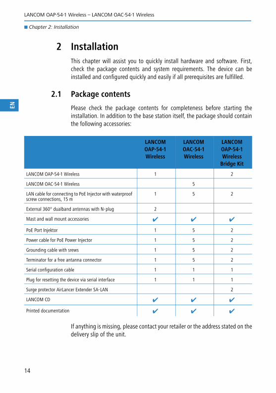
2.1 Package contents
Please check the package contents for completeness before starting theinstallation. In addition to the base station itself, the package should containthe following accessories:
If anything is missing, please contact your retailer or the address stated on thedelivery slip of the unit.
LANCOM OAP-54-1 Wireless
LANCOM OAC-54-1 Wireless
LANCOM OAP-54-1 Wireless
Bridge Kit
LANCOM OAP-54-1 Wireless 1 2
LANCOM OAC-54-1 Wireless 5
LAN cable for connecting to PoE Injector with waterproof screw connections, 15 m
1 5 2
External 360° dualband antennas with N-plug 2
Mast and wall mount accessories ✔ ✔ ✔
PoE Port Injektor 1 5 2
Power cable for PoE Power Injector 1 5 2
Grounding cable with srews 1 5 2
Terminator for a free antanna connector 1 5 2
Serial configuration cable 1 1 1
Plug for resetting the device via serial interface 1 1 1
Surge protector AirLancer Extender SA-LAN 2
LANCOM CD ✔ ✔ ✔
Printed documentation ✔ ✔ ✔
14

LANCOM OAP-54-1 Wireless – LANCOM OAC-54-1 Wireless
� Chapter 2: Installation
EN
2.2 System requirements
2.2.1 Configuring the LANCOM devices
Computers that connect to a LANCOM must meet the following minimumrequirements:
� Operating system that supports TCP/IP, e.g. Windows Vista™,Windows XP, Windows Millennium Edition (Me), Windows 2000, Win-dows 98, Linux, BSD Unix, Apple Mac OS, OS/2.
� Access to the LAN via the TCP/IP protocol.
� Wireless LAN adapter or LAN access (if the access point is to be connectedto the LAN).
The LANtools also require a Windows operating system. A web brow-ser under any operating system provides access to WEBconfig.
2.2.2 Operating access points in managed mode
LANCOM Wireless Routers and LANCOM Access Points can be operated eitheras self-sufficient Access Points with their own configuration ("Access Pointmode“) or as components in a WLAN infrastructure, which is controlled froma central WLAN-Controller ("managed mode").
2.3 Status displays and interfaces
Meanings of the LEDs
In the following sections we will use different terms to describe the behaviourof the LEDs:
� Blinking means, that the LED is switched on or off at regular intervals inthe respective indicated colour.
� Flashing means, that the LED lights up very briefly in the respectivecolour and stay then clearly longer (approximately 10x longer) switchedoff.
� Inverse flashing means the opposite. The LED lights permanently in therespective colour and is only briefly interrupted.
� Flickering means, that the LED is switched on and off in irregular inter-vals.
15

LANCOM OAP-54-1 Wireless – LANCOM OAC-54-1 Wireless
� Chapter 2: Installation
EN
2.3.1 LEDs of LANCOM OAP-54-1 Wireless and LANCOM OAC-54-1 Wireless
The front panel of the unit feature a series of light emitting diodes (LEDs) thatprovide information on the status of the device.
� Power This LED provides information on the device's operating state. After beingswitched on, it blinks green during the self-test. The LED then shines con-stantly to indicate operational readiness, unless an error is detected as indi-cated by a code blinked in red.
The power LED blinks alternately in green until a configuration pass-word has been set. Without a configuration password, the configura-tion data in the LANCOM are unprotected. Normally you would set aconfiguration password during the basic configuration (instructions inthe following chapter). Information about setting a configurationpassword at a later time is available in the section 'The SecurityWizard'.
� WLAN Link Provides information about the WLAN connections via the internal WLANmodule.
� � �
Off Device switched off
Green On (perma-nently)
Device operational
Red Blinking The device is locked because location verification was not successful
16

LANCOM OAP-54-1 Wireless – LANCOM OAC-54-1 Wireless
� Chapter 2: Installation
EN
The following can be displayed for WLAN link:
� ETH LAN connector status:
2.3.2 Connectors of LANCOM OAP-54-1 Wireless and LANCOM OAC-54-1 Wireless
The connections and switches of the LANCOM OAP-54-1 Wireless andLANCOM OAC-54-1 Wireless are located on the bottom side.
� Earth cable connector.
� Connector for serial configuration cable and reset plug (see 'The resetfunction').
� Aux connector for external antennas. Diversity antennas are connected tothe Aux connector.
Off No WLAN network defined or WLAN module deactiva-ted. The WLAN module is not transmitting beacons.
Green At least one WLAN network is defined and WLAN module activated. The WLAN module is transmitting beacons.
Green Inverse flashing Number of flashes = number of connected WLAN stati-ons and P2P wireless connections, followed by a pause (default).Alternatively, the frequency of the flashed can indicate the input sensitivity.
Green Blinking DFS scanning or other scan procedure.
Off No networking device attached
Green On (perma-nently)
Connection to network device operational, not data traffic
Green Flickering Data traffic
� �� �
17

LANCOM OAP-54-1 Wireless – LANCOM OAC-54-1 Wireless
� Chapter 2: Installation
EN
� Goretex membrane for compensation of fluctuations in pressure andhumidity.
Main connector for external antennas. Additional AirLancer antennas areconnected to the Main connectors if necessary. The integrated RF switchautomatically changes to the usage of an external antenna.
10/100Base-Tx for connection to the LAN. Both 10 Mbit or 100 Mbit con-nections are supported. The available transfer rate is detected automati-cally (autosensing). The LAN connection features an automatic MDI/MDIXdetector enabling the use of cross-over cables.The LAN connector on the LANCOM OAP/OAC-54-1 Wireless supportsPower over Ethernet (PoE).
The reset function
Via the serial interface the device can either be bootet (restarted) or reset (tothe factory settings).
Unsrew the fitting of the “COM/Reset” interface at the bottom of the device.Insert the reset plug to the serial interface. Via this plug, two connectors ofthe interface are bridged, which starts the reset process.
Press the reset plug briefly to re-start the device. Pressing the button for 5seconds or longer restarts the device and resets the configuration to its factorysettings. All LEDs on the device light up continuously. Once the switch isreleased the device will restart with the restored factory settings.
After resetting, the device starts completely unconfigured and allsettings are lost. If possible be sure to backup the current deviceconfiguration before resetting.
After resetting, the LANCOM Access Point returns to managed mode,in which case the configuration cannot be directly accessed via theWLAN interface!
18

LANCOM OAP-54-1 Wireless – LANCOM OAC-54-1 Wireless
� Chapter 2: Installation
EN
2.3.3 Mounting and connectiong the LANCOM OAP-54-1 Wireless and LANCOM OAC-54-1 Wireless
The material from the LANCOM OAP/OAC-54-1 Wireless includes beside thescrews, nuts and locking rings the following components:
Material
� Mounting arm
� Connector flange for the Access Point
� clamp profile
� Screw the Connector flange for the Access Point with the four M5 x 12-screws as well as with the appropriate washers to the rear of the chassis.
Before mounting external antennas, please observe the information on lightning pro-tection in the LANCOM Outdoor Wireless Guide. Mounting antennas without adequatelightning protection could lead to serious damage to the access point and the networkinfrastructure connected to it.
� �
�
19

LANCOM OAP-54-1 Wireless – LANCOM OAC-54-1 Wireless
� Chapter 2: Installation
EN
Preparationg
� Prepare for the mounting bores at the wall. Use for this the mounting armas a stencil. Screw the mounting arm � with the enclosed screws anddowels at the wall.
Wall mounting
Attach the Access Point with the connector flange at the mounting arm.Use for this the M8 x 110-screw with the locking washer, washer and nut.
Wall mounting
� Place for the pole mounting the clamp profile around the pole. Screw theclamp profile with the M8 x 110-screws at the mounting arm.
20

LANCOM OAP-54-1 Wireless – LANCOM OAC-54-1 Wireless
� Chapter 2: Installation
EN
Pole mounting
� To change the main beam direction of the integrated antennas, you canbend the Access Point up or down with the connector flange opposite themounting arm.
Adjusting of the Access Point
Installation of the LANCOM OAP/OAC-54-1 Wireless
For the installation of the LANCOM OAP/OAC-54-1 Wireless proceed as fol-lows:
� Earth connection - attach the earth cable to the earth screw of theLANCOM OAP/OAC-54-1 Wireless and to a suitable earthed conductor.
When mounting the LANCOM OAP/OAC-54-1 Wireless on poles orwalls it may be necessary to earth the housing to avoid dangerous dif-ferences in potential. For grounding the LANCOM OAP/OAC-54-1
21

LANCOM OAP-54-1 Wireless – LANCOM OAC-54-1 Wireless
� Chapter 2: Installation
EN
Wireless please observe the information on lightning protection in theattached LANCOM Outdoor Wireless Guide.
� Optional: Antenna terminal LANCOM OAP-54-1 Wireless – screw the sup-plied diversity antennas onto the two N connectors on the bottom side ofthe LANCOM OAP/OAC-54-1 Wireless.
When assembling separately purchased mobile radio antennas pleasenote that the maximum allowed transmission power of the wirelessLAN according to EIRP in the country in question may not beexceeded. The system operator is responsible for adhering to thethreshold values.
The employment of the AirLancer Extender SA-5L for internal light-ning protection is essential under all circumstances—theAirLancer Extender SA-5L is always mounted between the AccessPoint and the antenna, preferably as near as possible to the antenna.
Antennas are only to be attached or changed when the device isswitched off. Mounting or demounting antennas while the deviceswitched on may cause the destruction of the WLAN module!
LAN—The LAN connector is also used to supply power to the LANCOMOAP/OAC-54-1 Wireless. Plug in the water-proof power cable to the LANport on the underside of the device and carefully tighten the threadedconnector. Connect the other end of the power cable to the 'Power Out'connector on the supplied PoE Injector.
� DSLoL – If you want to use your access point in DSLoL mode, you caneither connect the device directly to the DSL modem (exclusive mode) orto a hub resp. switch of the cable-bound LAN (automatic mode).
� For the exclusive mode insert the included network cable (greenplugs) into the LAN connector of the device and the other end into thecorresponding interface of the DSL modem.
� For the automatic mode for simultaneous operating with LAN andDSLoL insert the included network cable (green plugs) into the LANconnector of the device and the other end into a free network con-necting socket of your local network (resp. into a free socket of a hub/switch).
22

LANCOM OAP-54-1 Wireless – LANCOM OAC-54-1 Wireless
� Chapter 2: Installation
EN
More information about using a LAN interface for DSLoL can be found inthe following information box → ’LAN interface: exclusive or in parallelfor DSLoL.
� PoE—the 'LAN In' connector of the supplied PoE Injector should be con-nected via a normal Ethernet cable to an available network connectionsocket in your local network (e.g. an available socket on a hub or switch)and the PoE Injector connected with the electricity supply.
Information about the installation of PoE can be found in the informationbox 'Power over Ethernet—elegant power supply over LAN cabling'above.
Please observe the information in the documentation supplied with thePoE Injector.
Use only the supplied PoE Injector for the power supply of theLANCOM OAP/OAC-54-1 Wireless. Pay particular care not to connectthe PoE Injector to normal Ethernet devices!
� Ready for operation? —the Power LED permanently lights up in green assoon as the device receives power. The LEDs subsequently display theoperational status.
LAN interface: exclusive or in parallel for DSLoL
There are two principle DSLoL operation modes available. Either use the exclusive mode whenconnecting your LANCOM Access Point directly to a DSL modem, or use the automatic modewhen connecting the Access Point to a hub or switch of a cable-bound LAN, and connect thishub/switch again to the DSL modem. Ifthe Access Point is broadcasted as gate-way via DHCP, computers in LAN andWLAN can use the internet connectionsimultaneously via one physical inter-face. Set the desired mode in LANconfigin the Interface settings of the DSLoLinterface.
DSLoL supports all PPPoE-based Internet access lines, as well as those that are sup-plied with a access router with multiple fixed IP addresses (such as many SDSL busi-ness lines).
23
LANCOM OAP-54-1 Wireless – LANCOM OAC-54-1 Wireless
� Chapter 2: Installation
EN
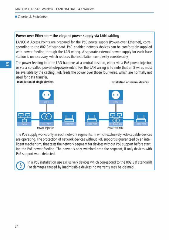
Power over Ethernet – the elegant power supply via LAN cabling
LANCOM Access Points are prepared for the PoE power supply (Power-over-Ethernet), corre-sponding to the 802.3af standard. PoE-enabled network devices can be comfortably suppliedwith power feeding through the LAN wiring. A separate external power supply for each basestation is unnecessary, which reduces the installation complexity considerably.
The power feeding into the LAN happens at a central position, either via a PoE power injector,or via a so-called powerhub/powerswitch. For the LAN wiring is to note that all 8 wires mustbe available by the cabling. PoE feeds the power over those four wires, which are normally notused for data transfer.
The PoE supply works only in such network segments, in which exclusively PoE-capable devicesare operating. The protection of network devices without PoE support is guaranteed by an intel-ligent mechanism, that tests the network segment for devices without PoE support before start-ing the PoE power feeding. The power is only switched onto the segment, if only devices withPoE support were detected.
In a PoE installation use exclusively devices which correspond to the 802.3af standard!For damages caused by inadmissible devices no warranty may be claimed.
Switch PoE - 48 V ACCESS POINT
230 V
Power Injector
Installation of single devices Installation of several devices
PoE Switch 48 V ACCESS POINTACCESS POINT
230 V
Power switch
24

LANCOM OAP-54-1 Wireless – LANCOM OAC-54-1 Wireless
� Chapter 2: Installation
EN
2.4 Software installation
The following section describes the installation of the Windows-compatiblesystem software LANtools, as supplied.
You may skip this section if you use your LANCOM OAP/OAC-54-1Wireless exclusively with computers running operating systems otherthan Windows.
2.4.1 Starting the software setup
Place the product CD into your drive. The setup program will start automati-cally.
If the setup does not start automatically, run AUTORUN.EXE in theroot directory of the LANCOM CD.
In Setup, select Install software. The following selection menus will appearon screen:
25

LANCOM OAP-54-1 Wireless – LANCOM OAC-54-1 Wireless
� Chapter 2: Installation
EN
2.4.2 Which software should I install?
� LANconfig is the Windows configuration program for all LANCOM rou-ters and LANCOM access points. WEBconfig can be used alternativelyor in addition via a web browser.
� With LANmonitor you can use a Windows computer to monitor all ofyour LANCOM routers and LANCOM access points.
� WLANmonitor enables the observation and surveillance of wirelessLAN networks. Clients connected to the access points are shown, andeven non-authenticated access points and clients can be displayed aswell (rogue AP detection and rogue client detection).
� With Documentation you copy the documentation files onto your PC.
Select the appropriate software options and confirm your choice with Next.The software is installed automatically.
26

LANCOM OAP-54-1 Wireless – LANCOM OAC-54-1 Wireless
� Chapter 3: Basic configuration
EN
3 Basic configurationThe basic configuration is conducted with a convenient Setup Wizard thatprovides step-by-step guidance through the configuration and that requestsany necessary information.
First of all this chapter presents the information that has to be entered for thebasic configuration. This first section will help you to gather up all of thenecessary data before you start the Wizard.
You subsequently enter this information into the Setup Wizard. Starting theprogram and the following procedure are described step by step. LANconfigand WEBconfig each have their own description. With all of the necessaryinformation collected in advance, this basic configuration can now take placequickly and in ease.
At the end of this chapter we show you the necessary settings for the work-place computers in the LAN so that they can access the device without pro-blem.
3.1 What details are necessary?
The Basic Settings Wizard is used to set the LANCOM OAP/OAC-54-1 Wirelesssbasic TCP/IP parameters and to protect the device with a configuration pass-word. The following description of the information required by the wizard isdivided into the following configuration sections:
� TCP/IP settings
� Protecting the configuration
� Security settings
3.1.1 TCP/IP settings
TCP/IP configuration can be performed in two different ways: Either fully auto-matically or manually. No user input is required if TCP/IP configuration is per-formed automatically. All parameters are set by the Setup Wizard on its own.When manual TCP/IP configuration is performed the wizard prompts for theusual TCP/IP parameters: IP address, network mask etc. (more on this later)
The fully automatic TCP/IP configuration is only possible in certain networkenvironments. For this reason the Setup Wwizard analyses the connected LANto see whether fully automatic configuration is possible or not.
27
LANCOM OAP-54-1 Wireless – LANCOM OAC-54-1 Wireless
� Chapter 3: Basic configuration
EN
New LAN – fully automatic configuration possible
The setup wizard offers to configure TCP/IP fully automatically if no networkdevices connected have yet been configured. This usually happens in the fol-lowing situations:
� Only a single PC is going to be attached to the LANCOM OAP/OAC-54-1Wireless
� Setting up a new network
Fully automatic TCP/IP configuration will not be offered if you are integratingthe LANCOM OAP/OAC-54-1 Wireless into an existing TCP/IP LAN. In this caseplease continue with the section 'Required information for manual TCP/IPconfiguration'.
The result of fully automatic TCP/IP configuration is as follows: The LANCOMOAP/OAC-54-1 Wireless is assigned the IP address '172.23.56.254' (networkmask '255.255.255.0'). The integrated DHCP server is also activated so thatthe LANCOM OAP/OAC-54-1 Wireless can assign the devices in the LAN IPaddresses automatically.
Should you still configure manually?
Fully automatic TCP/IP configuration is optional. Instead of this you can selectmanual configuration. Make this selection after considering the following:
� Select automatic configuration if you are not familiar with networks andIP addresses.
� Select manual TCP/IP configuration if you are familiar with networks andIP addresses and one of the following statements is true:
� You have not yet used any IP addresses in your network but would liketo now; You would like to specify the IP address for the router yourselfand would like to assign it a user-defined address from one of theaddress ranges reserved for private use, for example '10.0.0.1' witha network mask of '255.255.255.0'. If you do this you simultaneouslyspecify the address range that the DHCP server will subsequently usefor the other devices in the network (provided the DHCP server is acti-vated).
� You have so far also used IP addresses on the computers in the LAN.
Required information for manual TCP/IP configuration
When performing manual TCP/IP configuration the Setup Wwizard promptsyou for the following information:
28

LANCOM OAP-54-1 Wireless – LANCOM OAC-54-1 Wireless
� Chapter 3: Basic configuration
EN
� DHCP mode of operation
� Off: The IP addresses required must be entered manually.
� Server: The LANCOM OAP/OAC-54-1 Wireless operates as DHCP serverin the network; as a minimum its own IP address and the networkmask must be assigned.
� Client: The LANCOM OAP/OAC-54-1 Wireless obtains its address infor-mation from another DHCP server; no address information is required.
� IP address and network mask for the LANCOM OAP/OAC-54-1WirelessAssign the LANCOM OAP/OAC-54-1 Wireless a free IP address from yourLAN's address range and enter the network mask.
� Gateway address
Enter the gateway's IP address if you have selected 'Off' as the DHCPmode of operation or if another network device is assuming the role ofgateway in the 'Server' mode of operation.
� DNS server
Enter the IP address of a DNS server to resolve domain names if you haveselected 'Off' as the DHCP mode of operation or if another network deviceis assuming the role of DNS server in the 'Server' mode of operation.
3.1.2 Configuration protection
Using a password secures access to the LANCOM OAP/OAC-54-1 Wireless'sconfiguration and thus prevents unauthorized modification. The device's con-figuration contains a great deal of sensitive data such as data for Internetaccess and should be protected by a password in all cases.
Multiple administrators can be set up in the configuration of theLANCOM, each with differing access rights. Up to 16 different admi-nistrators can be set up for a LANCOM OAP/OAC-54-1 Wireless.Further information can be found in the LCOS reference manual under“Managing rights for different administrators”.
3.2 Instructions for LANconfig
� Start up LANconfig by clicking Start � Programs � LANCOM �LANconfig. LANconfig automatically detects the new LANCOM devices inthe TCP/IP network.
29

LANCOM OAP-54-1 Wireless – LANCOM OAC-54-1 Wireless
� Chapter 3: Basic configuration
EN
� If an unconfigured device is being found during searching, the setupwizard starts that will help you make the basic settings of the device orwill even do all the work for you (provided a suitable network environmentexists).
If the setup wizard does not start automatically, start a manual searchfor new devices in the network (Device � Find).
If you cannot access an unconfigured LANCOM, the problem may bedue to the netmask of the LAN: with less than 254 possible hosts (net-mask > '255.255.255.0'), please ensure that the IP address'x.x.x.254' is located in your own subnet.
If you have chosen automatic TCP/IP configuration, please continue withStep �.
If you would like to configure the TCP/IP settings manually, assign an avai-lable address from a suitable address range to the LANCOM. Confirm yourchoice with Next.
� Specify whether or not the router should act as a DHCP server. Make yourselection and confirm with Next.
� In the following window, specify the password for configuration access.Note that the password is case-sensitive and ensure that it is sufficientlylong (at least 6 characters).
In addition, you may specify whether the device may only be configuredfrom the local network or whether remote configuration via the WAN (i.e.a remote network) is also permissible.
Please note that enabling this will also permit remote configurationvia the Internet. You should always make sure that the configurationaccess is protected with a password.
30

LANCOM OAP-54-1 Wireless – LANCOM OAC-54-1 Wireless
� Chapter 3: Basic configuration
EN
� Enter the wireless parameters. Select a network name (SSID) and a radiochannel. Turn on if necessary the function for ’closed network’. Confirmyour choice with Next.
� In the next window, select your DSL provider from the list that is displayed.If you select 'My provider is not listed here,' you must enter the transferprotocol used by your DSL provider manually. Confirm your choice withNext.
� Connect charge protection can limit the cost of DSL connections to a pre-determined amount if desired. Confirm your choice with Next.
� Complete the configuration with Finish.
Section 'TCP/IP settings to workstation PCs' will describe the settingsrequired for the individual workstations in the LAN.
3.3 Instructions for WEBconfig
To configure the device with WEBconfig you must know how to address it inthe LAN. The reaction of the devices, as well as their accessibility for configu-ration via web browser is dependent on whether a DHCP server and a DNSserver are already active in the LAN, and whether these two server processesexchange the assignment of IP addresses to symbolic names within the LANbetween each other.
After powered on, unconfigured LANCOM devices check first, whether a DHCPserver is already active in the LAN. Dependent on the situation, the device isable to switch on its own DHCP server or, alternatively, to activate its DHCPclient mode. In this second operating mode, the device itself can obtain an IPaddress from a DHCP server already existing in the LAN.
If a LANCOM Wireless Router or LANCOM Access Point is centrallymanaged from a LANCOM WLAN Controller, the DHCP mode is swit-ched from auto-mode to client mode.
Network without DHCP server
Not for centrally managed LANCOM Wireless Router or LANCOM Access Points
In a network without DHCP server, unconfigured LANCOM devices activatetheir own DHCP server service after starting, and assign appropriate IPaddresses and gateway information to the other workstations within the LAN,provided that the workstations are set to obtain their IP address automatically(auto-DHCP). In this constellation, the device can be accessed with any web
31
LANCOM OAP-54-1 Wireless – LANCOM OAC-54-1 Wireless
� Chapter 3: Basic configuration
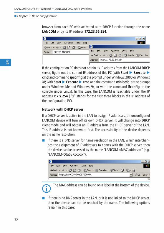
EN
browser from each PC with activated auto-DHCP function through the nameLANCOM or by its IP address 172.23.56.254.
If the configuration PC does not obtain its IP address from the LANCOM DHCPserver, figure out the current IP address of this PC (with Start � Execute �cmd and command ipconfig at the prompt under Windows 2000 or WindowsXP, with Start � Execute � cmd and the command winipcfg at the promptunder Windows Me and Windows 9x, or with the command ifconfig on theconsole under Linux). In this case, the LANCOM is reachable under the IPaddress x.x.x.254 ( “x” stands for the first three blocks in the IP address ofthe configuration PC).
Network with DHCP server
If a DHCP server is active in the LAN to assign IP addresses, an unconfiguredLANCOM device will turn off its own DHCP server. It will change into DHCPclient mode and will obtain an IP address from the DHCP server of the LAN.This IP address is not known at first. The accessibility of the device dependson the name resolution:
� If there is a DNS server for name resolution in the LAN, which interchan-ges the assignment of IP addresses to names with the DHCP server, thenthe device can be accessed by the name “LANCOM <MAC address>” (e.g.“LANCOM-00a057xxxxxx”).
The MAC address can be found on a label at the bottom of the device.
� If there is no DNS server in the LAN, or it is not linked to the DHCP server,then the device can not be reached by the name. The following optionsremain in this case:
http://LANCOM
http://172.23.56.254
http://LANCOM-00a05700094A
32

LANCOM OAP-54-1 Wireless – LANCOM OAC-54-1 Wireless
� Chapter 3: Basic configuration
EN
� Figure out the DHCP-assigned IP address of the LANCOM by suitabletools and contact the device directly with this IP address.
� Use LANconfig.
Starting the wizards in WEBconfig
� Start your web browser (e.g. Internet Explorer, Firefox, Opera) and call theLANCOM there:
http://<IP address of the LANCOM>
(or with a name as discribed above)
If you cannot access an unconfigured device, the problem may be dueto the netmask of the LAN: with less than 254 possible hosts (netmask> '255.255.255.0'), please ensure that the IP address 'x.x.x.254' islocated in your own subnet.
The WEBconfig main menu will be displayed:
33

LANCOM OAP-54-1 Wireless – LANCOM OAC-54-1 Wireless
� Chapter 3: Basic configuration
EN
The setup wizards are tailored precisely to the functionality of the spe-cific LANCOM model. As a result, your device may offer differentwizards than those shown here.
If you have chosen automatic TCP/IP configuration, please continue withStep .
� If you would like to configure the TCP/IP settings manually, assign an avai-lable address from a suitable address range to the LANCOM. Also setwhether or not it is to operate as a DHCP server. Confirm your entry withApply.
34

LANCOM OAP-54-1 Wireless – LANCOM OAC-54-1 Wireless
� Chapter 3: Basic configuration
EN
Enter the wireless parameters. Select a network name (SSID) and a radiochannel. Turn on if necessary the function for ’closed network’. Confirmyour choice with Next.
� In the following 'Security settings' window, specify a password for confi-guration access. Note that the password is case-sensitive and ensure thatit is sufficiently long (at least 6 characters).
You may specify whether the device may only be configured from the localnetwork or whether remote configuration via the WAN (i.e. a remote net-work) is also permissible.
Please note that enabling this will also permit remote configurationvia the Internet. You should always make sure that the configurationaccess is suitably protected, e.g. with a password.
� In the next window, select your DSL provider from the list that is displayed.Confirm your choice with Apply.
If you select 'My provider is not listed here,' you must enter the transferprotocol used by your DSL provider manually in the next window. Confirmyour choice with Apply.
� Connect charge protection can limit the cost of DSL connections to a pre-determined amount if desired. Confirm your choice with Apply.
� The basic setup wizard reports that all the necessary information has beenprovided. You can end the wizard with Go on.
Entering the password in the web browser
When you are prompted for a user name andpassword by your web browser when accessingthe device in the future, enter your personalvalues to the corresponding fields. Please notethat the password is case-sensitive.
If you are using the common configurationaccount, enter the corresponding password only.Leave the user name field blank.
Entering the configuration password
35

LANCOM OAP-54-1 Wireless – LANCOM OAC-54-1 Wireless
� Chapter 3: Basic configuration
EN
3.4 TCP/IP settings to workstation PCs
The correct addressing of all devices within a LAN is extremely important forTCP/IP networks. In addition, all computers must know the IP addresses of twocentral points in the LAN:
� Default gateway – receives all packets that are not addressed to compu-ters within the local network.
� DNS server – translates network names (www.lancom.de) or names ofcomputers (www.lancom.de) to actual IP addresses.
The LANCOM can perform the functions of both a default gateway and a DNSserver. In addition, as a DHCP server it can also automatically assign valid IPaddresses to all of the computers in the LAN.
The correct TCP/IP configuration of the PCs in the LAN depends on the methodused to assign IP addresses within the LAN:
� IP address assignment via the LANCOM (default)
In this operating mode the LANCOM not only assigns IP addresses to thePCs in the LAN, it also uses DHCP to specify its own IP address as that ofthe default gateway and DNS server. The PCs must therefore be configu-red so that they automatically obtain their own IP address and the IPaddresses of the standard gateway and DNS server (via DHCP).
� IP address assignment via a separate DHCP server
The workstation PCs must be configured so that they automatically obtaintheir own IP address and the IP addresses of the standard gateway andDNS server (via DHCP). The IP address of the LANCOM must be stored onthe DHCP server so that the DHCP server transmits it to the PCs in the LANas the standard gateway. In addition, the DHCP server should also specifythe LANCOM as a DNS server.
� Manual IP address assignment
If the IP addresses in the network are assigned static ally, then for each PCthe IP address of the LANCOM must be set in the TCP/IP configuration asthe standard gateway and as a DNS server.
For further information and help on the TCP/IP settings of yourLANCOM, please see the reference manual. For more information onthe network configuration of the workstation computers, please referto the documentation of your operating system.
36
LANCOM OAP-54-1 Wireless – LANCOM OAC-54-1 Wireless
� Chapter 4: Security settings
EN
4 Security settingsYour LANCOM device has numerous security functions. You find in this chapterall information needed for an optimal protection of the base station.
You can carry out the configuration of security settings very quicklyand conveniently with the Security Wizards in LANconfig andWEBconfig.
4.1 Security for the Wireless LAN
Reflecting on Wireless LANs often entails substantial doubts concerning secu-rity. Many people suppose that abuse of data transmitted via radio links isrelatively simple.
Wireless LAN devices by LANCOM Systems permit the employment of modernsecurity technologies:
� Closed network
� Access Control (via MAC addresses)
� LANCOM Enhanced Passphrase Security
� Encryption of data transfer (802.11i/WPA or WEP)
� 802.1x / EAP
� optional IPSec over WLAN (VPN), in combination with external VPN gate-way
4.1.1 Closed network
Each Wireless LAN according to IEEE 802.11 has its own network name (SSID).This network name serves as identification and enables administration ofWireless LANs.
A Wireless LAN can be established in such a way that any user gets access tothis network. Such networks are called open networks. Any user can accessan open network also without knowledge of the WLAN network name reser-ved specifically for this network. Only requirement is the input of the networkname 'ANY'.
In a closed network the access via 'ANY' is not possible. User have to specifythe correct network name. Unknown networks stay hidden to them.
Ad-hoc-networks are automatically installed as closed networks and cannotbe opened. Infrastructure networks can be run either in open or closed con-dition. You make the settings for this at the respective base station.
37
LANCOM OAP-54-1 Wireless – LANCOM OAC-54-1 Wireless
� Chapter 4: Security settings
EN
4.1.2 Access control via MAC address
Each network device has an special identification number. This identificationnumber is the so-called MAC address (Media Access Control), which is world-wide unique per device.
The MAC address is programmed into the hardware and cannot be changed.Wireless LAN devices by LANCOM Systems have got a MAC address label onthe casing.
The access to an infrastructure network can be restricted to known MACaddresses for certain Wireless LAN devices solely. To do so, Access Control listsare available within the LANCOM base stations, in which the granted MACaddresses can be deposited.
4.1.3 LANCOM Enhanced Passphrase Security
With LEPS (LANCOM Enhanced Passphrase Security) LANCOM Systems hasdeveloped an efficient method which uses the simple configuration of IEEE802.11i with passphrase and yet which avoids the potential error sources ofpassphrase sharing. LEPS uses an additional column in the ACL to assign anindividual passphrase consisting of any 4 to 64 ASCII characters to each MACaddress. The connection to the access point and the subsequent encryptionwith IEEE 802.11i or WPA is only possible with the right combination of pass-phrase and MAC address.
LEPS can be used locally in the device and can also be centrally managed withthe help of a RADIUS server, and it works with all WLAN client adapters cur-rently available on the market without modification. Full compatibility tothird-party products is assured as LEPS only involves configuration in theaccess point.
An additional security aspect: LEPS can also be used to secure single point-to-point connections (P2P) with an individual passphrase. Even if an accesspoint in a P2P installation is stolen and the passphrase and MAC addressbecome known, all other WLAN connections secured by LEPS remain protec-ted, particularly when the ACL is stored on a RADIUS server.
Guest access with LEPS: LEPS can also be set up to allow access toguests. To this end, all users of the internal WLAN network are givenindividual passphrases. Guests can make use of their own dedicatedSSID and a global passphrase. To avoid abuse, this global passphrasecan be changed on a regular basis—every few days, for example.
38

LANCOM OAP-54-1 Wireless – LANCOM OAC-54-1 Wireless
� Chapter 4: Security settings
EN
4.1.4 Encryption of the data transfer
A special role comes up to the encryption of data transfer for Wireless LANs.For IEEE 802.11 radio transfer the supplementing encryption standards are802.11i/WPA and WEP. The function of the encryption is to ensure the securitylevel of cable-bound LANs also in Wireless LANs.
� Use encryption on the data transferred in the WLAN. Activate the stron-gest possible encryption available to you ((802.11i with AES, WPA or WEP)and enter the appropriate keys or passphrases into the access point andthe WLAN clients.
� Regularly change the WEP keys in your access points. The passphrases for802.11i or WPA do not have to be changed regularly as new keys aregenerated for each connection anyway. This is not the only reason that theencryption with 802.11i/AES or WPA/TKIP is so much more secure thanthe now aged WEP method.
� If the data is of a high security nature, you can further improve the encryp-tion by additionally authenticating the client with the 802.1x method oractivate an additional encryption of the WLAN connection as used for VPNtunnels ('IPSec over WLAN'). In special cases, a combination of these twomechanisms is possible.
Further details to WLAN security and the used encoding methods canbe found in the LCOS reference manual.
4.1.5 802.1x / EAP
The international industry standard IEEE 802.1x and the Extensible Authenti-cation Protocol (EAP) enables the realization of reliable and secure accesscontrols for base stations. The access data is centrally administered on aRADIUS server then, and can be retrieved by the base station if required.
Moreover, this technology makes enables a secured dispatch and a regularautomatic change of WEP keys. In this way IEEE 802.1x improves the protec-tion efforts of WEP.
In Windows XP the IEEE-802.1x technology is already integrated by default.For other operating systems 802.1x client software is available.
The drivers for the LANCOM AirLancer wireless cards already feature an inte-grated 802.1x client.
39

LANCOM OAP-54-1 Wireless – LANCOM OAC-54-1 Wireless
� Chapter 4: Security settings
EN
4.1.6 IPSec over WLAN
By means of IPSec over WLAN a radio network can be optimally secured inaddition to the already introduced securing mechanisms. In order to run IPSecover WLAN you have to upgrade the base stations of the with the LANCOMVPN option and the LANCOM Advanced VPN Client, which runs under theoperating systems Windows VistaTM, Windows 2000 and Windows XP. Forother operating systems client software from other manufacturers is available.The drivers for the LANCOM AirLancer wireless adapter are already equippedwith a 802.1x client.
4.2 Tips for handling keys
The security of encryption procedures can be substantially increased the bypaying attention to some important rules for handling keys.
� Keep keys as secret as possible. Never note a key. Popular, but completely unsuitable are for example:notebooks, wallets and text files in PCs. Do not share a key unnecessarily.
� Select a random key.Use randomized keys of character and number sequences. Keys from thegeneral linguistic usage are insecure.
� Change a key immediately in case of suspicion.It is time to change the key of the Wireless LAN if an employee with accessto a key leaves your company. The key should also be renewed in case ofsmallest suspicion of a leak.
� LEPS prevents the global spread of passphrases.
Activate LEPS to enable the use of individual passphrases.
4.3 The security settings wizard
Access to the configuration of a device permits not only to read out criticalinformation (e.g. WEP key, Internet password). Rather, also the entire settingsof the security functions (e.g. firewall) can be altered then. So an unauthorizedconfiguration access endangers not only a single device, but the entire net-work.
Your LANCOM has a password protection for the configuration access. Thisprotection is already activated during the basic configuration by entering apassword.
40

LANCOM OAP-54-1 Wireless – LANCOM OAC-54-1 Wireless
� Chapter 4: Security settings
EN
The device locks access to its configuration for a specified period of time aftera certain number of failed log-in attempts. Both the number of failed attemptsand the duration of the lock can be set as needed. By default, access is lockedfor a period of five minutes after the fifth failed log-in attempt.
Besides these general settings you can also check the security settings of thewireless network with the security wizard as far as your device has a WLANinterface.
4.3.1 Wizard for LANconfig
� Mark your LANCOM in the selection window. Select from the commandbar Extras � Setup Wizard.
� Select in the selection menu the setup wizard Control Security Settingsand confirm your choice with Next.
Enter your password in the following windows and select the allowed pro-tocols for the configuration access from local and remote networks.
� In a next step parameters of the configuration lock like number of failedlog-in attempts and the duration of the lock can be adjusted.
� Now you can set the security settings for the WLAN. These include thename of the wireless network, the closed network function and the WEPencryption. You can type in the parameters for both wireless networksseparately on devices with the option of a second WLAN interface.
� Now you specify filter lists for stations (ACL) accessing the WLAN and pro-tocols. Thereby, you restrict data exchange between the wireless networkand the local network.
� Now activate Stateful Inspection, ping-blocking and Stealth mode in thethe firewall configuration.
41
LANCOM OAP-54-1 Wireless – LANCOM OAC-54-1 Wireless
� Chapter 4: Security settings
EN
� The wizard will inform you when entries are complete. Complete the con-figuration with Finish.
4.3.2 Wizard for WEBconfig
Under WEBconfig you have the possibility to run the wizard Security settingsto control and change the settings. The following values are handled:
� password for the device
� allowed protocols for the configuration access of local and remote net-works
� parameters of configuration lock (number of failed log-in attempts andduration of the lock)
� security parameters as WLAN name, closed network function, WEP key,ACL list and protocol filters
4.4 The security checklist
The following checklists provide an overview of all security settings that areimportant to professionals. Most of the points in this checklist are uncriticalfor simple configurations. In these cases, the security settings in the basicconfiguration or that were set with the Security Wizard are sufficient.
Detailed information about the security settings mentioned here areto be found in the reference manual.
� Have you protected the configuration with a password?
The simplest way of protecting the configuration is to agree upon a pass-word. If no password has been agreed for the device, the configuration isopen to be changed by anybody. The field for entering the password is tobe found in LANconfig in the 'Management' configuration area on the'Security' tab. It is absolutely imperative to assign a password to the con-figuration if you want to enable remote configuration!
� Have you permitted remote configuration?
If you do not require remote configuration, please ensure to switch it off.If you need to make use of remote configuration, ensure that you do notfail to password-protect the configuration (see the section above). Thefield for disenabling remote configuration is to be found in LANconfig inthe 'Management' configuration area on the 'Security' tab. Under ‘Accessrights – From remote networks’ select the option ‘denied’ for all methodsof configuration.
42

LANCOM OAP-54-1 Wireless – LANCOM OAC-54-1 Wireless
� Chapter 4: Security settings
EN
� Have your password-protected the SNMP configuration?
Protect the SNMP configuration with a password too. The field for pass-word-protecting the SNMP configuration is also to be found in LANconfigin the 'Management' configuration area on the 'Security' tab.
� Have you activated the firewall?
The stateful inspection firewall of LANCOM devices ensures that you localnetwork cannot be attacked from the outside. Activate the firewall inLANconfig under 'Firewall/QoS' on the 'General' tab.
� Are you using a 'deny all' firewall strategy?
Maximum security and control is initially achieved by denying all datatraffic from passing the firewall. The only connections to be accepted bythe firewall are those that are to be explicitly permitted. This ensures thatTrojan horses and certain types of e-mail virus are denied communicationto the outside. Activate the firewall rules in LANconfig under 'Firewall/QoS' on the 'Rules' tab. Instructions on this are to be found in the refe-rence manual.
� Have you activated IP masquerading?
IP masquerading refers to the concealment of local computers while theyaccess the Internet. All that is revealed to the Internet is the IP number ofthe router module of the device. The IP address can be fixed or dynami-cally assigned by the provider. The computers in the LAN then use the rou-ter as a gateway and are not visible themselves. The router separates theInternet from the intranet like a wall. The application of IP masqueradingis set in the routing table for every route individually. The routing table canbe found in the LANconfig in the configuration area 'IP router' on the'Routing' tab.
� Have you used filters to close critical ports?
The firewall filters in LANCOM devices offer filter functions for individualcomputers or entire networks. It is possible to set up source and destina-tion filters for individual ports or port ranges. Furthermore, filters can beset for individual protocols or any combination of protocols (TCP/UDP/ICMP). It is especially convenient to set up the filters with the aid ofLANconfig. Under 'Firewall/QoS', the 'Rules' tab contains the functions fordefining and editing filter rules.
� Have you excluded certain stations from accessing the device?
A special filter list can be used to limit access to the device's internal func-tions via TCP/IP. The phrase "internal functions" refers to configuration
43
LANCOM OAP-54-1 Wireless – LANCOM OAC-54-1 Wireless
� Chapter 4: Security settings
EN
sessions via LANconfig, WEBconfig, Telnet or TFTP. As standard this tablecontains no entries, meaning that computers with any IP address can useTCP/IP and Telnet or TFTP to commence accessing the device. The first timean IP address is entered with its associated netmask, the filter is activatedand only the IP addresses contained in this entry are entitled to make useof internal functions. Further entries can be used to extend the circle ofauthorized parties. The filter entries can describe individual computers oreven entire networks. The access list can be found in the LANconfig in theconfiguration area 'TCP/IP' on the 'General' tab.
� Do you store your saved LANCOM configuration to a safe location?
Protect your saved configurations in a location that is safe from unautho-rized access. Otherwise, by way of example, an unauthorized person mayload your stored configuration file into another device and they can accessthe Internet at your expense.
44

LANCOM OAP-54-1 Wireless – LANCOM OAC-54-1 Wireless
� Chapter 5: Advanced wireless LAN configuration
EN
5 Advanced wireless LAN configuration
5.1 WLAN configuration with the wizards in LANconfig
Highly convenient installation wizards are available to help you with the con-figuration of LANCOM Access Points for your wireless LAN.
The settings include the general shared parameters and also the individualsettings for one or more logical wireless LAN networks (WLAN radio cells orSSIDs).
� Mark your LANCOM Access Point in the selection window in LANconfig.From the command line, select Extras � Setup Wizard.
� In the selection menu, select the Setup Wizard, Configure WLAN inter-face and confirm the selection with Continue.
Make the settings as requested by the wizard and as described as follows.
Country settings
Regulations for the operation of WLAN cards differ from country to country.The use of some radio channels is prohibited in certain countries. To operatethe LANCOM Access Points while observing the regulations in various coun-tries, all physical WLAN interfaces can be set up for the country where theyare operated.
WLAN module operation
The WLAN modules can be operated in various operating modes:
� As a base station (Access Point mode), the device makes the link betweenWLAN clients and the cabled LAN. Parallel to this, point-to-point connec-tions are possible as well.
� In Managed Mode the Access Points also accept WLAN clients into thenetwork, although the clients then join a WLAN infrastructure that is con-
45
LANCOM OAP-54-1 Wireless – LANCOM OAC-54-1 Wireless
� Chapter 5: Advanced wireless LAN configuration
EN
figured by a central WLAN-Controller. In this operating mode, no furtherWLAN configuration is necessary as all WLAN parameters are provided bythe WLAN-Controller.
� In client mode, the device itself locates the connection to another AccessPoint and attempts to register with a wireless network. In this case thedevice serves, for example, to link a cabled network device to an AccessPoint over a wireless connection. In this operating mode, parallel point-to-point connections are not possible.
For further information please refer to section → Client Mode.
Physical WLAN settings
Along with the radio channels, the physical WLAN settings can also be usedto activate options such as the bundeling of WLAN packets (TX Burst), hard-ware compression, or the use of QoS compliant with 802.11e. You also controlthe settings for the diversity behavior here.
Logical WLAN networks
Each WLAN module can support up to eight logical WLAN networks formobile WLAN clients to register with. The following parameters have to be setwhen configuring a logical WLAN network:
� The network name (SSID)
� Open or closed radio LAN
� Encryption settings
� MAC filter
� Client-bridge operation
� Filter settings
Point- to-point settings
The configuration of P2P connections involves setting not only the operatingmode but also the station name that the Access Point can connect to. Also,the role as "Master" or "Slave" is set here.
Along with the settings for the Access Point itself, also to be defined is theremote site that the Access Point can contact via the P2P connection.
For further information please refer to section → Point-to-point connections.
46

LANCOM OAP-54-1 Wireless – LANCOM OAC-54-1 Wireless
� Chapter 5: Advanced wireless LAN configuration
EN
5.2 Point-to-point connections
LANCOM Access Points can serve not only as central stations in a wireless net-work, they can also operate in point-to-point mode to bridge longer dis-tances. For example, they can provide a secure connection between twonetworks that are several kilometers apart — without direct cabling or expen-sive leased lines.
The behavior of an access point when exchanging data with other accesspoints is defined in the "Point-to-point operation mode".
� Off: The access point only communicates with mobile clients
� To: The access point can communicate with other access points and withmobile clients
� Exclusive: The access point only communicates with other base stations
In the 5 -GHz band, the automatic search for vacant WLAN channels can leadto several simultaneous test transmissions from multiple access points, withthe result that they do not find each other. This stalemate situation can beavoided with the appropriate "Channel selection scheme":
� Master: This access point takes over the leadership when selecting a freeWLAN channel.
� Slave: All other access points will search for a channel until they havefound a transmitting Master.
WLAN Router ANTENNA
BUILDINGACCESS POINTANTENNA
BUILDING
ACCESS POINTANTENNA
BUILDING
47

LANCOM OAP-54-1 Wireless – LANCOM OAC-54-1 Wireless
� Chapter 5: Advanced wireless LAN configuration
EN
Thus it is recommended for the 5 GHz band that one central access pointshould be configured as 'Master' and all other point-to-point partners shouldbe configured as 'Slave'. In the 2.4 GHz band, too, this setting simplifies theestablishment of point-to-point connections if the automatic channel searchis activated.
It is imperative that the channel selection scheme is configured cor-rectly if the point-to-point connections are to be encrypted with802.11i/WPA.
5.2.1 Geometric dimensioning of outdoor wireless network links
The following basic questions must be answered when designing wirelesslinks:
� What antennas must be used for the desired application?
� How must the antennas be positioned to ensure a problem-free connec-tion?
� What performance characteristics do the antennas need to ensure suffi-cient data throughput within the legal limits?
Selection of antennas using the LANCOM Antenna Calculator
You can use the LANCOM Antenna Calculator to calculate the output powerof the access points as well as the achievable distances and data rates. Theprogram can be downloaded from our website at www.lancom.eu.
After selecting your components (access points, antennas, lightning protec-tion and cable) the calculator works out the data rates, ranges, and theantenna gain settings that have to be entered into the access point.
MASTER ANTENNE
SLAVEANTENNE
SLAVEANTENNE
48

LANCOM OAP-54-1 Wireless – LANCOM OAC-54-1 Wireless
� Chapter 5: Advanced wireless LAN configuration
EN
Please note that when using 5 GHz antennas additional technologiessuch as dynamic frequency selection (DFS) may be stipulated depen-ding on the country of use. The operator of the wireless LAN system isresponsible for ensuring that local regulations are met.
Positioning the antennas
Antennas do not broadcast their signals linearly, but within an angle thatdepends on the model in question. The spherical expansion of the signalwaves results in amplification of or interference to the effective power output
49
LANCOM OAP-54-1 Wireless – LANCOM OAC-54-1 Wireless
� Chapter 5: Advanced wireless LAN configuration
EN
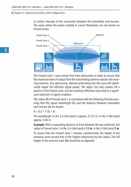
at certain intervals of the connection between the transmitter and receiver.The areas where the waves amplify or cancel themselves out are known asFresnel zones.
The Fresnel zone 1 must remain free from obstruction in order to ensure thatthe maximum level of output from the transmitting antenna reaches the recei-ving antenna. Any obstructing element protruding into this zone will signifi-cantly impair the effective signal power. The object not only screens off aportion of the Fresnel zone, but the resulting reflections also lead to a signifi-cant reduction in signal reception.
The radius (R) of Fresnel zone 1 is calculated with the following formula assu-ming that the signal wavelength (λ) and the distance between transmitterand receiver (d) are known.
R = 0.5 * √ (λ * d)
The wavelength in the 2.4 GHz band is approx. 0.125 m, in the 5 GHz bandapprox. 0.05 m.
Example: With a separating distance of 4 km between the two antennae, theradius of Fresnel zone 1 in the 2.4-GHz band is 11 m, in the 5-GHz band 7 m.
To ensure that the Fresnel zone 1 remains unobstructed, the height of theantennas must exceed that of the highest obstruction by this radius. The fullheight of the antenna mast (M) should be as depicted:
WLAN Router
ANTENNA
ADMINISTRATION ACCESS POINT
ANTENNA
PRODUCTIONOBSTRUCTION
Fresnel zone 1
Fresnel zone 2
Fresnel zone 3 Radius R
Distance d
50
LANCOM OAP-54-1 Wireless – LANCOM OAC-54-1 Wireless
� Chapter 5: Advanced wireless LAN configuration
EN
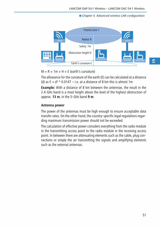
M = R + 1m + H + E (earth's curvature)
The allowance for the curvature of the earth (E) can be calculated at a distance(d) as E = d² * 0.0147 – i.e. at a distance of 8 km this is almost 1m
Example: With a distance of 8 km between the antennae, the result in the2.4-GHz band is a mast height above the level of the highest obstruction ofapprox. 13 m, in the 5-GHz band 9 m.
Antenna power
The power of the antennas must be high enough to ensure acceptable datatransfer rates. On the other hand, the country-specific legal regulations regar-ding maximum transmission power should not be exceeded.
The calculation of effective power considers everything from the radio modulein the transmitting access point to the radio module in the receiving accesspoint. In between there are attenuating elements such as the cable, plug con-nections or simply the air transmitting the signals and amplifying elementssuch as the external antennas.
WLAN Router
ANTENNA
ADMINISTRATION WLAN Router
ANTENNA
PRODUCTIONOBSTRUCTION
Fresnel zone 1
Radius R
Safety: 1m
Obstruction height H
Earth's curvature E
51

LANCOM OAP-54-1 Wireless – LANCOM OAC-54-1 Wireless
� Chapter 5: Advanced wireless LAN configuration
EN
5.2.2 Antenna alignment for P2P operations
The precise alignment of the antennas is of considerable importance in esta-blishing P2P connections. The more central the receiving antenna is locatedin the "ideal line" of the transmitting antenna, the better are the actual per-formance and the effective bandwidth �. If the receiving antenna is outsideof this ideal area, however, significant losses in performance will be the result�.
You can find further information on the geometrical design of wirelesspaths and the alignment of antennas with the help of LANCOM soft-ware in the LCOSreference manual.
The current signal quality over a P2P connection can be displayed on thedevice's LEDs or in the LANmonitor in order to help find the best possiblealignment for the antennas.
WLAN Router
ANTENNA
ADMINISTRATION ACCESS POINT
ANTENNA
PRODUCTION
SA-5L SA-5L
Free-space lossAmplification with antenna gain
Output power of the radio module
Loss throughcable, plugs andlightning protec-
tion
Amplification with antenna gain
Input signal at theradio module
Loss through cable, plugs and lightning protec-tion
WLAN Router
ANTENNE
VERWALTUNG ACCESS POINT
ANTENNE
PRODUKTION
ANTENNE
�
�
52

LANCOM OAP-54-1 Wireless – LANCOM OAC-54-1 Wireless
� Chapter 5: Advanced wireless LAN configuration
EN
The display of signal quality on the LEDs must be activated for the wirelessLAN interface (LANconfig: Wireless LAN � General � Physical WLANsettings � Operation). The faster the LED blinks the better the connection(a blinking frequency of 1 Hz represents a signal quality of 10 dB, double thefrequency indicates that the signal strength is twice as high).
In LANmonitor the connection quality display is opened with the contextmenu. Right-clicking with the mouse on 'Point-to-point' activates the option'Adjusting Point-to-Point WLAN Antennas...'
The 'Point-to-point' entry is only visible in the LANmonitor if themonitored device has at least one base station defined as a remotestation for a P2P connection (LANconfig: Wireless LAN � General� Physical WLAN settings � Point- to-Point).
In the dialog for setting up point-to-point connections, LANmonitor promptsfor the information required to establish the P2P connection:
� Is the P2P connection configured at both ends (remote base station defi-ned with MAC address or station name)?
� Is the point-to-point mode of operation activated?
� Which access point is to be monitored? All of the base stations defined asP2P remote stations in the device concerned can be selected here.
53
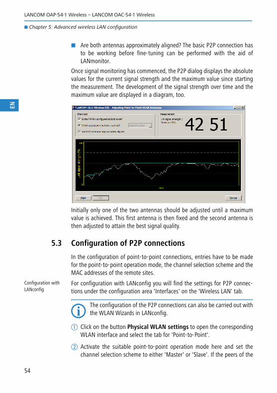
LANCOM OAP-54-1 Wireless – LANCOM OAC-54-1 Wireless
� Chapter 5: Advanced wireless LAN configuration
EN
� Are both antennas approximately aligned? The basic P2P connection hasto be working before fine-tuning can be performed with the aid ofLANmonitor.
Once signal monitoring has commenced, the P2P dialog displays the absolutevalues for the current signal strength and the maximum value since startingthe measurement. The development of the signal strength over time and themaximum value are displayed in a diagram, too.
Initially only one of the two antennas should be adjusted until a maximumvalue is achieved. This first antenna is then fixed and the second antenna isthen adjusted to attain the best signal quality.
5.3 Configuration of P2P connections
In the configuration of point-to-point connections, entries have to be madefor the point-to-point operation mode, the channel selection scheme and theMAC addresses of the remote sites.
Configuration with LANconfig
For configuration with LANconfig you will find the settings for P2P connec-tions under the configuration area 'Interfaces' on the 'Wireless LAN' tab.
The configuration of the P2P connections can also be carried out withthe WLAN Wizards in LANconfig.
� Click on the button Physical WLAN settings to open the correspondingWLAN interface and select the tab for 'Point-to-Point'.
� Activate the suitable point-to-point operation mode here and set thechannel selection scheme to either 'Master' or 'Slave'. If the peers of the
54

LANCOM OAP-54-1 Wireless – LANCOM OAC-54-1 Wireless
� Chapter 5: Advanced wireless LAN configuration
EN
55
P2P connections are to be identified via their station names, then enter aunique name for this WLAN station.
For models with multiple WLAN modules, the station name can beentered separately for each physical WLAN interface.
Close the physical WLAN settings and open the list of Point- to-pointpartners. For each of the maximum of six P2P connections, enter eitherthe MAC address of the WLAN card at the remote station or enter theWLAN station's name (depending on the chosen method of identifica-tion).
Please observe that only the MAC addresses of the WLAN cards at theother end of the connections are to be entered here! Not the accesspoint's own MAC address, and not the MAC addresses from any otherinterfaces that may be present in the access points.

LANCOM OAP-54-1 Wireless – LANCOM OAC-54-1 Wireless
� Chapter 5: Advanced wireless LAN configuration
EN
You will find the WLAN MAC address on a sticker located under each of theantenna connectors. Only use the string that is marked as the "WLAN MAC"or "MAC-ID". The other addresses that may be found are not the WLAN MACaddress but the LAN MAC address.
Alternatively you will find the MAC addresses for the WLAN cards in thedevices under WEBconfig, Telnet or a terminal program under the followingpaths:
Configuration with WEBconfig or Telnet
Under WEBconfig or Telnet you can set the settings for the point-to-pointconnections under the following paths:
5.3.1 Security for point-to-point connections
IEEE 802.11i can be used to attain a significant increase in the security ofWLAN point-to-point connections. All of the advantages of 802.11i such asthe simple configuration and the powerful encryption with AES are thus avai-lable for P2P mode, as are the improved security of the passphrase from theLANCOM Enhance Passphrase Security (LEPS).
Encryption with 802.11i/WPA
To activate the 802.11i encryption for a correctly configured P2P connection,adjust the settings for the first logical WLAN network in the appropriateWLAN interface (i.e. WLAN-1 if you are using the first WLAN card for the P2P
Configuration tool Menu/Table
WEBconfig Expert configuration � Status � WLAN-statistics � Inter-face-statistics
Terminal/Telnet Status/WLAN-statistics/Interface-statistics
Configuration tool Menu/Table
WEBconfig Expert configuration � Setup � Interfaces � WLAN-Inter-faces� Interpoint-Settings
Terminal/Telnet cd /Setup/Interfaces/WLAN-Interfaces/Interpoint-Settings
56

LANCOM OAP-54-1 Wireless – LANCOM OAC-54-1 Wireless
� Chapter 5: Advanced wireless LAN configuration
EN
connection, WLAN-2 if you are using the second card, e.g. as with an accesspoint with two WLAN modules).
� Activate the 802.11i encryption.
� Select the method '802.11i (WPA)-PSK'.
� Enter the passphrase to be used.
The passphrases should consist of a random string at least 22 charac-ters long, corresponding to a cryptographic strength of 128 bits.
When set as P2P Master, the passphrase entered here will be used to checkthe Slave's authorization to access. When set as P2P Slave, the access pointtransfers this information to register with the remote site.
Configuration with LANconfig
For configuration with LANconfig you will find the encryption settings underthe configuration area 'Wireless LAN' on the '802.11i/WEP' tab.
Configuration with WEBconfig or Telnet
The encryption settings for the individual logical WLAN networks can befound under WEBconfig or Telnet under the following paths:
Configuration tool Menu/Table
WEBconfig Expert configuration � Setup � Interfaces � WLAN-Inter-faces� Encryption-Settings
Terminal/Telnet /Setup/Interfaces/WLAN-Interfaces/Encryption-Set-tings
57

LANCOM OAP-54-1 Wireless – LANCOM OAC-54-1 Wireless
� Chapter 5: Advanced wireless LAN configuration
EN
LEPS for P2P connections
A further gain in security can be attained by additionally using LANCOMEnhanced Passphrase Security (LEPS) which involves the matching of MACaddress and passphrase.
LEPS can be used to secure single point-to-point (P2P) connections with anindividual passphrase. Even if an access point in a P2P installation is stolenand the passphrase and MAC address become known, all other WLAN con-nections secured by LEPS remain secure.
When using LANconfig for the configuration, you enter the passphrases of thestations approved for the WLAN in the configuration area 'Wireless LAN' onthe 'Stations' tab under the button Stations.
Configuration with WEBconfig or Telnet
The access list for the matching of MAC addresses to the passphrases (LEPS)can be found under WEBconfig or Telnet under the following paths:
5.4 Client mode
To connect individual devices with an Ethernet interface into a wireless LAN,LANCOM devices with a WLAN module can be switched to "client mode",whereupon they act as conventional wireless LAN adapters and not as accesspoints (AP). The use of client mode therefore allows devices fitted with onlyan Ethernet interface, such as PCs and printers, to be integrated into a wire-less LAN.
Configuration tool Menu/Table
WEBconfig Expert configuration � Setup � WLAN-module � Access-list
Terminal/Telnet Setup/WLAN-module/Access-list
58
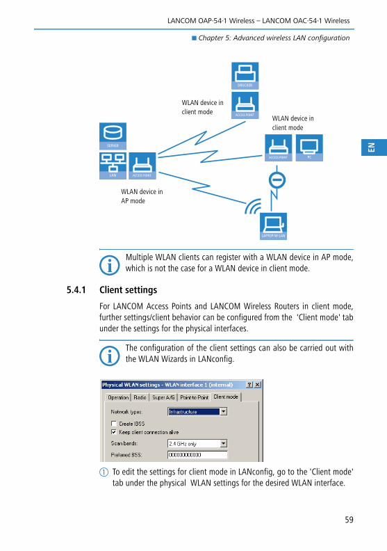
LANCOM OAP-54-1 Wireless – LANCOM OAC-54-1 Wireless
� Chapter 5: Advanced wireless LAN configuration
EN
Multiple WLAN clients can register with a WLAN device in AP mode,which is not the case for a WLAN device in client mode.
5.4.1 Client settings
For LANCOM Access Points and LANCOM Wireless Routers in client mode,further settings/client behavior can be configured from the 'Client mode' tabunder the settings for the physical interfaces.
The configuration of the client settings can also be carried out withthe WLAN Wizards in LANconfig.
� To edit the settings for client mode in LANconfig, go to the 'Client mode'tab under the physical WLAN settings for the desired WLAN interface.
ACCESS POINT
LAPTOP/W-LAN
DRUCKER
SERVER
LAN
ACCESS POINT
ACCESS POINT PC
WLAN device in client mode
WLAN device in AP mode
WLAN device in client mode
59
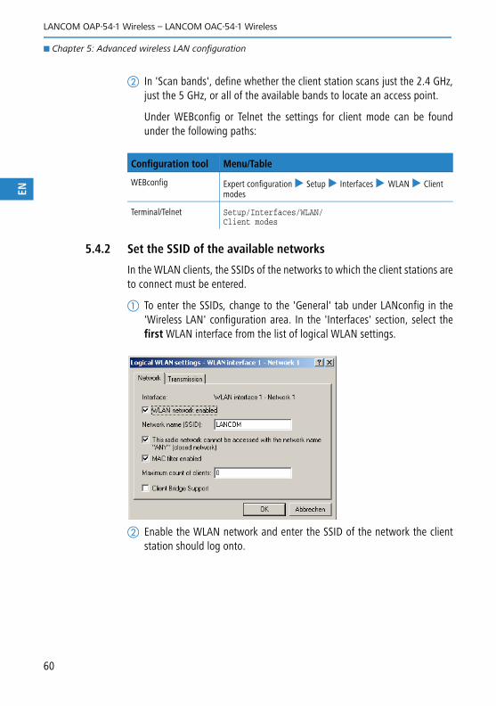
LANCOM OAP-54-1 Wireless – LANCOM OAC-54-1 Wireless
� Chapter 5: Advanced wireless LAN configuration
EN
� In 'Scan bands', define whether the client station scans just the 2.4 GHz,just the 5 GHz, or all of the available bands to locate an access point.
Under WEBconfig or Telnet the settings for client mode can be foundunder the following paths:
5.4.2 Set the SSID of the available networks
In the WLAN clients, the SSIDs of the networks to which the client stations areto connect must be entered.
� To enter the SSIDs, change to the 'General' tab under LANconfig in the'Wireless LAN' configuration area. In the 'Interfaces' section, select thefirst WLAN interface from the list of logical WLAN settings.
� Enable the WLAN network and enter the SSID of the network the clientstation should log onto.
Configuration tool Menu/Table
WEBconfig Expert configuration � Setup � Interfaces � WLAN � Client modes
Terminal/Telnet Setup/Interfaces/WLAN/Client modes
60

LANCOM OAP-54-1 Wireless – LANCOM OAC-54-1 Wireless
� Chapter 5: Advanced wireless LAN configuration
EN
Under WEBconfig or Telnet the network settings for the logical WLANinterfaces can be found under the following paths:
5.4.3 Encryption settings
For access to a WLAN, the appropriate encryption methods and key must beset in the client station.
� To enter the key, change to the '802.11i/WEP' tab under LANconfig in the'Wireless LAN' configuration area. From 'WPA / private WEP settings',select the first WLAN interface from the list of logical WLAN settings.
� Enable encryption and match the encryption method to the settings forthe access point.
In WLAN client operating mode, the LANCOM Access Points and LANCOMWireless Routers can authenticate themselves to another access pointusing EAP/802.1X. For this, select the desired client EAP method here.Note that the selected client EAP method must match the settings of theaccess point that the device is attempting to log onto.
Depending on the EAP method, the appropriate certificates must bestored in the device.
Configuration tool Menu/Table
WEBconfig Expert configuration � Setup � Interfaces � WLAN � Net-work
Terminal/Telnet Setup/Interfaces/WLAN/Network settings
61

LANCOM OAP-54-1 Wireless – LANCOM OAC-54-1 Wireless
� Chapter 5: Advanced wireless LAN configuration
EN
� For TTLS and PEAP - the EAP/TLS root certificate only; the key is ente-red as a combination username:password.
� For TLS in addition; the EAP/TLS device certificate including the privatekey.
Under WEBconfig or Telnet the network settings for the logical WLANinterfaces can be found under the following paths:
Configuration tool Call
WEBconfig, Telnet Expert configuration > Setup > Interfaces > WLAN > Encryp-tion > WLAN 1
62

LANCOM OAP-54-1 Wireless – LANCOM OAC-54-1 Wireless
� Chapter 6: Setting up Internet access
EN
6 Setting up Internet accessThe LANCOM provides a central point of Internet access for all of the compu-ters in the LAN. The connection to the Internet provider can be established viathe WAN connection which is connected to an ADSL or cable modem.
Does the Setup Wizard know your Internet provider?
The Wizard is preset with access data for the principal Internet providers inyour country and offers you a selection list. If you find your Internet providerin this list, then you generally do not have to enter any additional parametersto set up your Internet access. All that is required is the authentication dataas supplied to you by your Internet provider.
Internet provider unknown
If the list in the Setup Wizard does not contain your provider, you will be askedstep-by-step for all of the necessary data. This access data will have been sup-plied to you by your Internet provider.
Other connection options
In addition you can use the Wizard to activate or deactivate additional options(if supported by your Internet provider):
� Billing by time or flatrate – select the method by which you are billed byyour Internet provider.
� In case of billing by time, you can set the LANCOM to cut connectionsautomatically if no data flows for a certain time (the hold time).
You can also set up line polling that detects inactive remote stationsvery quickly and, in such cases, can close the connection before thehold time expires.
INTERNET
HEADQUARTER
SERVER LAN GATEWAYROUTER
63

LANCOM OAP-54-1 Wireless – LANCOM OAC-54-1 Wireless
� Chapter 6: Setting up Internet access
EN
� In case of flatrate billing you can also set up line polling to monitorthe function of the remote station.
Apart from that you can opt to keep flatrate connections permanentlyactive ("keep-alive"). In case a connection should fail, it is re-estab-lished automatically.
6.1 The Internet Connection Wizard
6.1.1 Instructions for LANconfig
� Mark your device in the selection window. From the command line, selectExtras � Setup Wizard.
� In the selection menu, select the Setup Wizard, Set up Internet connec-tion and confirm the selection with Next.
In the following windows you select your country, your Internet providerif possible, and you enter your access data.
� Depending on availability the Wizard provides further options for yourInternet connection.
� The Wizard will inform you as soon as the entries are complete. Close theconfiguration with Finish.
LANconfig: Fast activation of the Setup Wizards
The fastest way of starting the Setup Wizardsunder LANconfig is to use the command buttonin the button bar.
64
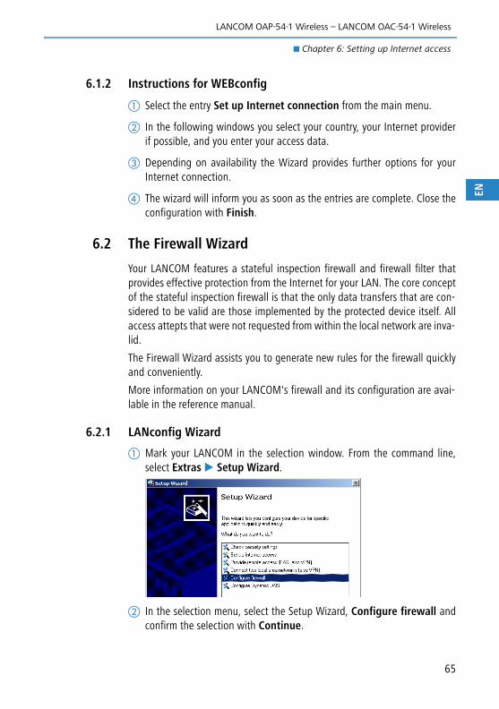
LANCOM OAP-54-1 Wireless – LANCOM OAC-54-1 Wireless
� Chapter 6: Setting up Internet access
EN
6.1.2 Instructions for WEBconfig
� Select the entry Set up Internet connection from the main menu.
� In the following windows you select your country, your Internet providerif possible, and you enter your access data.
Depending on availability the Wizard provides further options for yourInternet connection.
� The wizard will inform you as soon as the entries are complete. Close theconfiguration with Finish.
6.2 The Firewall Wizard
Your LANCOM features a stateful inspection firewall and firewall filter thatprovides effective protection from the Internet for your LAN. The core conceptof the stateful inspection firewall is that the only data transfers that are con-sidered to be valid are those implemented by the protected device itself. Allaccess attepts that were not requested from within the local network are inva-lid.
The Firewall Wizard assists you to generate new rules for the firewall quicklyand conveniently.
More information on your LANCOM's firewall and its configuration are avai-lable in the reference manual.
6.2.1 LANconfig Wizard
� Mark your LANCOM in the selection window. From the command line,select Extras � Setup Wizard.
� In the selection menu, select the Setup Wizard, Configure firewall andconfirm the selection with Continue.
65

LANCOM OAP-54-1 Wireless – LANCOM OAC-54-1 Wireless
� Chapter 6: Setting up Internet access
EN
In the windows that follow you select the services/protocols that the ruleis to relate to. In the next step you define the source and destination sta-tions that the rule applies to, and the actions that are to be carried out bythe rule on a data packet.
� Finally the new rule is given a name, it is activated, and you define whe-ther further rules are to be considered when the rule acts on a datapacket.
� The wizard will inform you as soon as the entries are complete. Close theconfiguration with Finish.
6.2.2 Configuration under WEBconfig
WEBconfig provides the option of checking and altering the parameters forInternet access under Configuration � Firewall / QoS � Rules � Ruletable.
66
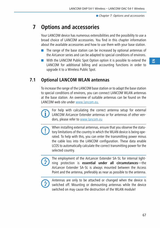
LANCOM OAP-54-1 Wireless – LANCOM OAC-54-1 Wireless
� Chapter 7: Options and accessories
EN
7 Options and accessoriesYour LANCOM device has numerous extensibilities and the possibility to use abroad choice of LANCOM accessories. You find in this chapter informationabout the available accessories and how to use them with your base station.
� The range of the base station can be increased by optional antennas ofthe AirLancer series and can be adapted to special conditions of environs.
� With the LANCOM Public Spot Option option it is possible to extend theLANCOM for additional billing and accounting functions in order toupgrade it to a Wireless Public Spot.
7.1 Optional LANCOM WLAN antennas
To increase the range of the LANCOM base station or to adapt the base stationto special conditions of environs, you can connect LANCOM WLAN antennasat the base station. An overview of suitable antennas can be found on theLANCOM web site under www.lancom.eu.
For help with calculating the correct antenna setup for externalLANCOM AirLancer Extender antennas or for antennas of other ven-dors, please refer to www.lancom.eu
When installing external antennas, ensure that you observe the statu-tory limitations of the country in which the WLAN device is being ope-rated. To help with this, you can enter the transmitting power minusthe cable loss into the LANCOM configuration. These data enableLCOS to automatically calculate the correct transmitting power for theselected country.
The employment of the AirLancer Extender SA-5L for internal light-ning protection is essential under all circumstances—theAirLancer Extender SA-5L is always mounted between the AccessPoint and the antenna, preferably as near as possible to the antenna.
Antennas are only to be attached or changed when the device isswitched off. Mounting or demounting antennas while the deviceswitched on may cause the destruction of the WLAN module!
67

LANCOM OAP-54-1 Wireless – LANCOM OAC-54-1 Wireless
� Chapter 7: Options and accessories
EN
7.1.1 Antenna Diversity
LANCOM OAP-54-1 Wireless only
The transmission of radio signals can suffer from significant signal lossesbecause of reflection and scatter, among other reasons. In some areas, theinteraction with the reflected radio waves can cause a drop in signal strength,or even cause it to be cancelled out completely.
Transmission quality can be improved with so-called "diversity" methods. Theprinciple of diversity methods relies on the fact that a transmitted signal isoften received multiple times (generally twice). With appropriate processing,these signals can be re-combined into a single signal. The most commonmethods are space diversity and polarization diversity.
LANCOM Systems supplies a variety of polarization-diversity antennas asaccessories for LANCOM Access Points and LANCOM Wireless Routers. Thesemodels enable two orthogonally polarized signals to be received with a singleantenna. Further information about this technique is available in our "Polari-zation Diversity" techpaper.
7.1.2 Installation of AirLancer Extender antennas
Polarization diversity antennas from LANCOM Systems:
� AirLancer Extender O-D80g (2.4 GHz band ), item no. 61221
� AirLancer Extender O-D60a (5 GHz band ), item no. 61222
� AirLancer Extender O-D9a (5 GHz), item no. 61224
Before mounting external antennas, please observe the informationon lightning protection in the LANCOM Outdoor Wireless Guide (avai-lable as a download from www.lancom.eu). Mounting antennas wit-hout adequate lightning protection could lead to serious damage tothe access point and the network infrastructure connected to it.
LANCOM OAP-54-1 Wireless
The integrated antennas of the LANCOM OAP-54-1 Wireless are best-suitedfor establishing point-to-point connections. When using the device in accesspoint mode, for getting more antenna gain or to use the diversity function itis recommended to apply external antennas.
To install the provided omni-directional antenna or optional AirLancer Exten-der antennas, switch the device off by disconnecting the PoE supply. Carefullyunscrew the terminators. Connect the antenna to the appropriate 'AntennaMain' connector. When connecting the external antenna to the Main connec-tor, the internal antenna is automatically deactivated.
68

LANCOM OAP-54-1 Wireless – LANCOM OAC-54-1 Wireless
� Chapter 7: Options and accessories
EN
7.2 LANCOM Public Spot Option
Wireless public spots are publicly accessible points, at which users with theirown mobile computers can dial wirelessly into a network, usually into theInternet.
The Wireless LAN technology is ideally suitable to offer wireless Internet ser-vices to the public at places such as airports, hotels, stations, restaurants orcafés, so-called Public Hot Spots. The LANCOM Public Spot Option is intendedfor operators of public wireless networks, and unveils additional functions forauthentication and billing of public Internet services for the LANCOM, thusenabling a simple set-up and maintenance of public hot spots.
The LANCOM Public Spot Option is the optimal solution for public WirelessLANs. Wireless LANs are very suitable for company networks and for wireless
With a LANCOM OAP-54-1 Wireless you can additionally use the „Tx diver-sity“ function via the Aux connector. Further information about diversitycan be found in the LCOS reference manual.
'Antenna Main' connector for AirLancer antennas
'AUX' connector for diversity antennas
Please note that the operation of a LANCOM OAP/OAC-54-1Wireless with LANCOM Public Spot Option (sometimes referred asHotSpot) is possibly subject to certain legal regulations. Pleaseinform yourself concerning relevant regulations before installing aLANCOM OAP/OAC-54-1 Wireless. Further information to this topiccan be found in our whitepaper „Public Spots - Operators' rightsand obligations“, available as download from www.lancom.eu.
69

LANCOM OAP-54-1 Wireless – LANCOM OAC-54-1 Wireless
� Chapter 7: Options and accessories
EN
networking at home. But for public access services, there is a lack of mecha-nisms for authentication and billing of single users (AAA - Authentication /Authorisation / Accounting). This lack remedies the LANCOM Systems OpenUser Authentication (OUA), the main part of the LANCOM Public Spot Option.The OUA procedure realizes the authentication of all wireless clients via username and password, and checks the authorization of single users via RADIUS.Accounting data (online time and data volume) can be transferred per userand per session to a central RADIUS server. Client PCs need only radio card(e.g. AirLancer), TCP/IP and an Internet browser. Additional software is notneeded. Therefore, the public spot option is ideally suitable to install wirelessInternet access services in hotels, restaurants, cafés, airports, stations, exhi-bition centres or universities.
With the LANCOM Public Spot Option you extend a base station additionallywith these functions and upgrade it to a Wireless Public Spot.
Mobile user
HTTP/HTTPS
Router
RADIUS
Internet
RADIUS-Server
Service-Provider
Authorisation,Accounting
Authentication
70

LANCOM OAP-54-1 Wireless – LANCOM OAC-54-1 Wireless
� Chapter 8: Troubleshooting
EN
8 TroubleshootingIn this chapter, you will find suggestions and assistance for a few common dif-ficulties.
8.1 No DSL connection is established
After start-up the router automatically attempts to connect to the DSL pro-vider. During this process, the LAN-link LED will blink green. If successful, theLED will switch over to steady green. If, however, the connection can't beestablished, the LAN-link LED will light up red. The reason for this is usuallyone of the following:
Problems with the cabling?
Only the cable provided with your device should be used to connect to DSL.This cable must be connected to the Ethernet port of your broadband accessdevice. The LAN link LED must light green indicating the physical connection.
Has the correct transfer protocol been selected?
The transfer protocol is set along with the basic settings. The basic setup wiz-ard will enter the correct settings for numerous DSL providers automatically.Only if your DSL provider is not listed, you will have to enter manually the pro-tocol being used. In any case, the protocol that your DSL provider supplies youwith should definitely work.
You can monitor and correct the protocol settings under:
8.2 DSL data transfer is slow
The data transfer rate of an broadband (Internet) DSL connection is dependentupon numerous factors, most of which are outside of one's own sphere ofinfluence. Important factors aside from the bandwidth of one's own Internetconnection are the Internet connection and current load of the desired target.Numerous other factors involving the Internet itself can also influence thetransfer rate.
Configuration tool Run command
LANconfig Management � Interfaces � Interface settings � WAN Inter-face
WEBconfig Expert Configuration � Setup � Interfaces � WAN Interface
71

LANCOM OAP-54-1 Wireless – LANCOM OAC-54-1 Wireless
� Chapter 8: Troubleshooting
EN
Increasing the TCP/IP window size under Windows
If the actual transfer rate of a DSL connection is significantly below the fastestrate listed by the provider, there are only a few possible causes (apart from theabove-mentioned external factors) which may involve one's own equipment.
One common problem occurs when large amounts of data are sent andreceived simultaneously with a Windows PC using an asynchronous connec-tion. This can cause a severe decrease in download speed. The cause of thisproblem is what is known as the TCP/IP receive window size of the Windowsoperating system that is set to a value too small for asynchronous connec-tions.
Instructions on how to increase the Windows size can be found in the Knowl-edge Base of the support section of the LANCOM web site (www.lancom.eu).
8.3 Unwanted connections under Windows XP
Windows XP computers attempt to compare their clocks with a timeserver onthe Internet at start-up. This is why when a Windows XP in the WLAN isstarted, a connection to the Internet is established by the LANCOM.
To resolve this issue, you can turn off the automatic time synchronization onthe Windows XP computers under Right mouse click on the time of day �Properties � Internet time.
72

LANCOM OAP-54-1 Wireless – LANCOM OAC-54-1 Wireless
� Chapter 9: Appendix
EN
9 Appendix
9.1 Performance data and specifications
LANCOM OAP-54-1 Wireless LANCOM OAC-54-1 Wireless
Frequency band WLAN module with 2400 - 2483,5 MHz (ISM) or 5150 - 5725 MHz and 5725 - 5850 (UK only)
Connections LAN 10/100Base-TX, Autosensing, Auto Node-Hub
WLAN 2x N socket with antenna diversity
Power supply Via Power over Ethernet only. One PoE Injector supplied.
Antennas Two dualband dipole antennas sup-plied.
Please respect the restrictions given in your country when setting up an antenna system. For information about calculating the correct antenna setup, please refer to www.lancom.eu
Housing 235 mm x 210 mm x 80 mm (W x H x D), 3.4kg, robust metal housing, IP66 water-jet resistant, ready for wall and pole mounting, 3 LEDs for status display
Approvals CE compliant according to ETSI EN 300 328, ETSI EN 301 893 Version 1.3.1 (incl. DFS 2), ETSI EN 301 489-1, ETSI EN 301 489-17, EN 60950-1
Regulations Notified in Germany, Belgium, Netherlands, Luxemburg, Austria, Switzerland, United Kingdom, Italy, France, Czechia, DenmarkThe courrent list of notifications can be found at www.lancom.eu
Environment/Temperature
Temperature range –30 °C bis +70 °C at 95 % max. humidity (non condensing)
Service Warranty: 3 years
Support Via hotline and Internet
73

LANCOM OAP-54-1 Wireless – LANCOM OAC-54-1 Wireless
� Chapter 9: Appendix
EN
9.2 Contact assignment
9.2.1 LAN/WAN interface 10/100Base-TX, DSL interface
8-pin RJ45 socket, corresponding to ISO 8877, EN 60603-7
9.2.2 Configuration interface (Outband)
8-pin mini-DIN socket
Connector Pin IAE
1 T+
2 T-
3 R+
4 PoE/G
5 PoE/G
6 R-
7 PoE/-48 V
8 PoE/-48 V
Connector Pin IAE
1 DSR
2 RI
3 DCD
4 DTR
5 TXD
6 RTS
7 CTS
8 RXD
9 RST (Reset)
10 GND
74

LANCOM OAP-54-1 Wireless – LANCOM OAC-54-1 Wireless
� Chapter 9: Appendix
EN
9.3 Declaration of conformity
LANCOM Systems herewith declares that the devices of the type described inthis documentation are in agreement with the basic requirements and otherrelevant regulations of the 1995/5/EC directive.
The CE declarations of conformity for your device are available in the appro-priate product area on the LANCOM Systems web site (www.lancom.eu).
75

LANCOM OAP-54-1 Wireless – LANCOM OAC-54-1 Wireless
� Index
EN
IndexNumerics100-Mbit network 18802.11i 11, 37, 38, 39802.1x 11, 37, 39802.3af- standard 24
AAccess point mode 9, 15ACL 38Antenna
Outdoor 67Antenna Calculator 48Antenna power 51Autosensing 18
CClient mode 58, 59Closed network 11Configuration access 30, 35Configuration file 44Configuration password 42Configuration protection 29Connect charge protection 31, 35Contact assignment 74
Configutation interface 74LAN interface 74Outband 74
DDefault gateway 36, 43DFS 49DHCP 12, 36
DHCP server 28, 30, 34, 36DNS 12
DNS server 10, 36Documentation 14Download 5DSL
provider 31, 35
transfer protocol 35DSL connection
problems establishing the connection 71
DSL transfer protocol 31DSLoL 22Dynamic Frequency Selection 49Dynamic frequency selection 49
EEAP 11, 37, 39Encryption methods 61
FFirewall 10, 12, 43
Block stations 43Firewall filters 65FirmSafe 12Firmware 5Flatrate 63Fresnel zone 50
IICMP 43Information symbols 5Installation 14
LANtools 25Internet access 63
Authentication data 63Flatrate 63
Internet access setup 63Internet provider 63Internet-Zugang 10IP
Block ports 43Filter 43
IP address 28, 29, 44IP masquerading 12, 43
76

LANCOM OAP-54-1 Wireless – LANCOM OAC-54-1 Wireless
� Index
EN
LLAN
Connector cable 14LANCOM Enhanced Passphrase Security 37LANconfig 26, 29
Starting the Wizards 64LANmonitor 26LANtools
System requirements 15LEDs
see status displays 16LEPS 11, 38
MMAC address filter 11Managed mode 9, 15mount accessories 14Multi SSID 11
NNAT – see IP masqueradingNetmask 28, 44Network mask 29
OOptional antennas 67Options and accessories 67
PP2P 38Password 29, 30PAT – see IP masqueradingPoE Power Injector 14Point-to-Point 38Point-to-point 47point-to-point 10Power-over-Ethernet 24Public Spot Option 69
QQoS 12Quality of Service 12
RRADIUS 11Remote configuration 30, 35Routing table 43
SSecurity
Wireless LAN 37Security checklist 42self-sufficient 9, 15SNMP
Configuration protection 43Software installation 25SSID 31, 35, 60Stateful Inspection Firewall 10Stateful- inspection firewall 65Status display
ETH 17WLAN link 17
StatusanzeigenPower 16
Super AG 11Support 5System requirements 15
TTCP 43TCP/IP 15
Settings 27, 30, 34Settings to PCs in the LAN 36Windows size 72
TCP/IP configurationAutomatic 34Fully automatic 27, 28Manual 27, 28
TCP/IP filter 12, 43Technische Daten 73Telnet 44TFTP 44Transfer protocol 71Turbo Modus 11
77

LANCOM OAP-54-1 Wireless – LANCOM OAC-54-1 Wireless
� Index
EN
UUDP 43
WWEBconfig 31
password 35System requirements 15
WEP 11
Wireless LANsOperating modes 9
WLANBands scanned 60Client mode 59
WPA 11, 37, 38, 39
78