Ladder, ventilated and solid trough - tnb.ca · Ladder, ventilated and solid trough. . A113. T&B...
48
www.tnb.ca A112 Metallic – Steel T&B ® Cable Tray Ladder Formed side rails are welded to 1-5/8 in. wide rungs to provide maximum rigidity and strength. Rung design includes exclusive Ty-Rap ® cable tie slots on 1 in. centers. Ventilated A fabricated structure consisting of integral or separate longitudinal rails and a bottom having openings sufficient for the passage of air and utilizing 75% or less of the plan area of the surface to support cables. The maximum open spacings between cable support surfaces of transverse elements do not exceed 102 mm (4 in.) in the direction parallel to the tray side rails (rung to rung). Solid Trough Solid sheet welded to steel side rails below rungs. This design offers added cable protection. Straight Lengths Tray Bottom Ladder, ventilated and solid trough
Transcript of Ladder, ventilated and solid trough - tnb.ca · Ladder, ventilated and solid trough. . A113. T&B...

w w w . t n b . c aA112
Metallic – SteelT&B ® Cable Tray
LadderFormed side rails are welded to 1-5/8 in. wide rungs to provide maximum rigidity and strength. Rung design includes exclusive Ty-Rap® cable tie slots on 1 in. centers.
VentilatedA fabricated structure consisting of integral or separate longitudinal rails and a bottom having openings sufficient for the passage of air and utilizing 75% or less of the plan area of the surface to support cables.
The maximum open spacings between cable support surfaces of transverse elements do not exceed 102 mm (4 in.) in the direction parallel to the tray side rails (rung to rung).
Solid TroughSolid sheet welded to steel side rails below rungs. This design offers added cable protection.
Straight LengthsTray BottomLadder, ventilated and solid trough
w w w . t n b . c a A113
Metallic – SteelT&B ® Cable Tray
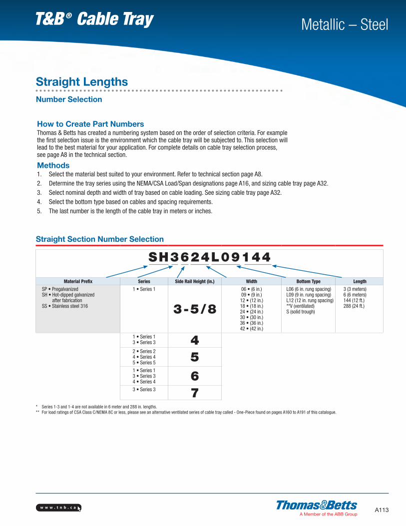
Straight Section Number Selection
SH3624L09144
Material Prefix Series Side Rail Height (in.) Width Bottom Type Length
SP • PregalvanizedSH • Hot-dipped galvanized
after fabricationSS • Stainless steel 316
1 • Series 1
3-5/8
06 • (6 in.)09 • (9 in.)12 • (12 in.)18 • (18 in.)24 • (24 in.)30 • (30 in.)36 • (36 in.)42 • (42 in.)
L06 (6 in. rung spacing)L09 (9 in. rung spacing)L12 (12 in. rung spacing)**V (ventilated)S (solid trough)
3 (3 meters)6 (6 meters)144 (12 ft.)288 (24 ft.)
1 • Series 13 • Series 3 42 • Series 24 • Series 45 • Series 5 51 • Series 13 • Series 34 • Series 4 63 • Series 3 7
* Series 1-3 and 1-4 are not available in 6 meter and 288 in. lengths.** For load ratings of CSA Class C/NEMA 8C or less, please see an alternative ventilated series of cable tray called - One-Piece found on pages A160 to A191 of this catalogue.
How to Create Part NumbersThomas & Betts has created a numbering system based on the order of selection criteria. For example the first selection issue is the environment which the cable tray will be subjected to. This selection will lead to the best material for your application. For complete details on cable tray selection process, see page A8 in the technical section.
Methods1. Select the material best suited to your environment. Refer to technical section page A8.2. Determine the tray series using the NEMA/CSA Load/Span designations page A16, and sizing cable tray page A32.3. Select nominal depth and width of tray based on cable loading. See sizing cable tray page A32.4. Select the bottom type based on cables and spacing requirements.5. The last number is the length of the cable tray in meters or inches.
Straight LengthsNumber Selection

w w w . t n b . c aA114
Metallic – SteelT&B ® Cable Tray
Straight Section Number Selection
SH1324L09-3
Material Prefix Series Side Rail Height Width Bottom Type Length
SP • PregalvanizedSH • Hot-dipped galvanized
after fabricationSS • Stainless steel 316
1 • Series 1 3 • (3-5/8 in.) 06 • (6 in.)09 • (9 in.)12 • (12 in.)18 • (18 in.)24 • (24 in.)30 • (30 in.)36 • (36 in.)42 • (42 in.)
L06 • 6 in. rung spacingL09 • 9 in. rung spacingL12 • 12 in. rung spacingV • Ventilated *S • Solid trough
3 • (3 meters)144 • (12 ft.)
* For load CSA Class C3M, NEMA 8C or less, please see an alternative ventilated series of cable tray called - One-Piece found on pages A160 to A191 of this catalogue.
Technical SpecificationsAll calculations and data are based on 42 in. wide cable trays with rungs spaced 12 inches center to center with tray supported as simple spans with deflection measured at the midpoint. Continuous spans may reduce deflection by as much as 50%.
Deflection factor: For lighter loads, deflection at any length can be calculated by multiplying the load by the deflection factor.For Fittings consult pages A50 to A91.
Straight Lengths3-5/8 in. Straight SectionsSeries 1-3Ladder, ventilated and solid trough
SeriesSupport Span (Feet)
6 8 10 12
SP1-3SH1-3SS1-3
Load (lb.)/ft.) 200 112.5 72 50
Deflection (in.) 0.242 0.430 0.672 0.967
Deflection Factor 0.001 0.004 0.009 0.019

w w w . t n b . c a A115
Metallic – SteelT&B ® Cable Tray
DimensionsSP1-3, SH1-3, SS1-3
W (in.) Wi (in.)
6 4.5
9 7.5
12 10.5
18 16.5
24 22.5
30 28.5
36 34.5
42 40.5
Technical SpecificationsLOAD RATINGS: 1.5 Safety factor. All tray sections will support an additional 200 lb. concentrated load on any portion of tray (side rail, rung, etc.) above and beyond published load class.
Series Dimensions Side Rail Design Factors • 1 Pair
Classifications
NEMA CSA UL ABS
SP1-3SH1-3SS1-3
Ix = 0.804 in.4 Sx = 0.444 in.3
Area = 0.488 in.212A C/3 m UL cross sectional
Area : 0.40 in.2Stainless steel
only
WI
2.58
7
W3.
625
0.750
3.62
5
Straight Lengths3-5/8 in. Straight SectionsSeries 1-3Ladder, ventilated and solid trough

w w w . t n b . c aA116
Metallic – SteelT&B ® Cable Tray
Straight Lengths4 in. Straight SectionsSeries 1-4, 3-4Ladder, ventilated and solid trough
Straight Section Number Selection
SH3424L09144
Material Prefix Series Side Rail Height Width Bottom Type Length *SP • PregalvanizedSH • Hot-dipped galvanized after fabricationSS • Stainless steel 316
1 • Series 13 • Series 3
4 • (4 in.) 06 • (6 in.)09 • (9 in.)12 • (12 in.)18 • (18 in.)24 • (24 in.)30 • (30 in.)36 • (36 in.)42 • (42 in.)
L06 • 6 in. rung spacingL09 • 9 in. rung spacingL12 • 12 in. rung spacingV • Ventilated **S • Solid trough
3 • (3 meters)6 • (6 meters)144 • (12 ft.)288 • (24 ft.)
* Series 1-4 not available in 6 meters or 288 in. lengths.** For load CSA Class C3M, NEMA 8C or less, please see an alternative ventilated series of cable tray called - One-Piece found on pages A160 to A191 of this catalogue.
Technical SpecificationsAll calculations and data are based on 42 in. wide cable trays with rungs spaced on 12 in. centers with tray supported as simple spans with deflection measured at the midpoint. Continuous spans may reduce deflection by as much as 50%.
Deflection factor: For lighter loads, deflection at any length can be calculated by multiplying the load by the deflection factor.For Fittings consult pages A50 to A91.
SeriesSupport Span (Feet)
6 8 10 12 14 16 18 20
SP1-4SH1-4SS1-4
Load (lb.)/ft.) 420 236 151 105 – – – –
Deflection (in.) 0.207 0.368 0.574 0.827 – – – –
Deflection Factor 0.001 0.002 0.004 0.008 – – – –
SP3-4SH3-4SS3-4
Load (lb.)/ft.) 556 313 200 139 102 78 62 50
Deflection (in.) 0.243 0.432 0.674 0.971 1.322 1.727 2.185 2.698
Deflection Factor 0.0004 0.0014 0.0033 0.00700 0.0130 0.022 0.035 0.054

w w w . t n b . c a A117
Metallic – SteelT&B ® Cable Tray
DimensionsSP1-4, SH1-4, SS1-4SP3-4, SH3-4, SS3-4
W (in.) Wi (in.)
6 3.34
9 6.34
12 9.34
18 15.34
24 21.34
30 27.34
36 33.34
42 39.34
Technical SpecificationsLOAD RATINGS: 1.5 Safety factor. All tray sections will support an additional 200 lb. concentrated load on any portion of tray (side rail, rung, etc.) above and beyond published load class.
Series Dimensions Side Rail Design Factors • 1 Pair
ClassificationsNEMA CSA UL ABS
SP1-4SH1-4SS1-4
Ix = 1.974 in.4 Sx = 0.788 in.3
Area = 0.682 in.212C D/3M UL cross sectional
Area : 0.70 in.2Stainless steel
only
SP3-4SH3-4SS3-4
Ix = 2.224 in.4 Sx = 1.022 in.3
Area = 1.080 in.220A D/6M UL cross sectional
Area : 0.70 in.2Stainless steel
only
4.18
8
WI
W
Straight Lengths4 in. Straight SectionsSeries 1-4, 3-4Ladder, ventilated and solid trough
1.328
1.328
4.18
84.
188

w w w . t n b . c aA118
Metallic – SteelT&B ® Cable Tray
Straight Lengths5 in. Straight SectionsSeries 2-5, 4-5, 5-5Ladder, ventilated and solid trough
Straight Section Number Selection
SH2524L09144
Material Prefix Series Side Rail Height Width Bottom Type Length
SP • PregalvanizedSH • Hot-dipped galvanized
after fabricationSS • Stainless steel 316
2 • Series 24 • Series 45 • Series 5
5 • (5 in.) 06 • (6 in.)09 • (9 in.)12 • (12 in.)18 • (18 in.)24 • (24 in.)30 • (30 in.)36 • (36 in.)42 • (42 in.)
L06 • 6 in. rung spacingL09 • 9 in. rung spacingL12 • 12 in. rung spacingV • Ventilated S • Solid trough
3 • (3 meters)6 • (6 meters)144 • (12 ft.)288 • (24 ft.)
Technical SpecificationsAll calculations and data are based on 42 in. wide cable trays with rungs spaced on 12 in. centers with tray supported as simple spans with deflection measured at the midpoint. Continuous spans may reduce deflection by as much as 50%.
Deflection factor: For lighter loads, deflection at any length can be calculated by multiplying the load by the deflection factor. For Fittings consult pages A50 to A91.
SeriesSupport Span (Feet)
6 8 10 12 14 16 18 20
SP2-5SH2-5SS2-5
Load (lb.)/ft.) 556 313 200 139 102 78 62 50
Deflection (in.) 0.187 0.332 0.519 0.747 1.017 1.329 1.682 2.076
Deflection Factor 0.0003 0.0011 0.0026 0.0054 0.0100 0.0170 0.0271 0.042
SP4-5SH4-5SS4-5
Load (lb.)/ft.) 833 469 300 208 153 117 93 75
Deflection (in.) 0.216 0.384 0.600 0.864 1.176 1.536 1.944 2.400
Deflection Factor 0.003 0.0008 0.0021 0.0043 0.0077 0.0131 0.0211 0.0320
SP5-5SH5-5SS5-5
Load (lb.)/ft.) – 625 400 278 204 156 123 100
Deflection (in.) – 0.414 0.647 0.932 1.268 1.657 2.097 2.589
Deflection Factor – 0.0007 0.0016 0.0034 0.0062 0.0106 0.0169 0.0259

w w w . t n b . c a A119
Metallic – SteelT&B ® Cable Tray
5.18
8
WI
W
Straight Lengths5 in. Straight SectionsSeries 2-5, 4-5, 5-5Ladder, ventilated and solid trough
DimensionsSP2-5, SH2-5, SS2-5, SP4-5,
SH4-5, SS4-5, SP5-5, SH5-5, SS5-5
W (in.) Wi (in.)
6 3.34
9 6.34
12 9.34
18 15.34
24 21.34
30 27.34
36 33.34
42 39.34
Technical SpecificationsLOAD RATINGS: 1.5 Safety factor. All tray sections will support an additional 200 lb. concentrated load on any portion of tray (side rail, rung, etc.) above and beyond published load class.
Series Dimensions Side Rail Design Factors • 1 Pair
Classifications
NEMA CSA UL ABS
SP2-5SH2-5SS2-5
Ix = 2.89 in.4 Sx = 1.09 in.3
Area = 0.778 in.220A D/6M UL cross sectional
Area : 0.70 in.2Stainless steel
only
SP4-5SH4-5SS4-5
Ix = 3.75 in.4 Sx = 1.40 in.3
Area = 1.018 in.220B E/6M UL cross sectional
Area : 1.00 in.2Stainless steel
only
SP5-5SH5-5SS5-5
Ix = 4.635 in.4Sx = 1.732 in.3Area = 1.24 in.2
20C ExceedsE/6M
UL cross sectionalArea : 1.00 in.2
Stainless steelonly
5.18
8
1.328
5.18
8
1.328
5.18
8
1.328

w w w . t n b . c aA120
Metallic – SteelT&B ® Cable Tray
Straight Lengths6 in. Straight SectionsSeries 1-6, 3-6, 4-6Ladder, ventilated and solid trough
Straight Section Number Selection
SH3624L12-6
Material Prefix Series Side Rail Height Width Bottom Type Length
SP • PregalvanizedSH • Hot-dipped galvanized
after fabricationSS • Stainless Steel 316
1 • Series 13 • Series 34 • Series 4
6 • (6 in.) 06 • (6 in.)09 • (9 in.)12 • (12 in.)18 • (18 in.)24 • (24 in.)30 • (30 in.)36 • (36 in.)42 • (42 in.)
L06 • 6 in. rung spacingL09 • 9 in. rung spacingL12 • 12 in. rung spacingV • Ventilated **S • Solid trough
3 • (3 meters)6 • (6 meters)144 • (12 ft.)288 • (24 ft.)
** For load ratings of CSA Class C/NEMA 8C or less, please see an alternative ventilated series of cable tray called - One-Piece found on pages A160 to A191 of this catalogue.
Technical SpecificationsAll calculations and data are based on 42 in. wide cable trays with rungs spaced on 12 in. centers with tray supported as simple spans with deflection measured at the midpoint. Continuous spans may reduce deflection by as much as 50%.
Deflection factor: For lighter loads, deflection at any length can be calculated by multiplying the load by the deflection factor.For Fittings consult pages A50 to A91.
SeriesSupport Span (Feet)
6 8 10 12 14 16 18 20
SP1-6SH1-6SS1-6
Load (lb.)/ft.) 556 313 200 139 102 78 62 50
Deflection (in.) 0.122 0.216 0.338 0.486 0.662 0.865 1.095 1.351
Deflection Factor 0.0002 0.0007 0.0017 0.0036 0.0065 0.0111 0.0177 0.0270
SP3-6SH3-6SS3-6
Load (lb.)/ft.) 833 469 300 208 153 117 93 75
Deflection (in.) 0.151 0.268 0.419 0.603 0.821 1.072 1.357 1.675
Deflection Factor 0.0002 0.0006 0.0014 0.0030 0.0055 0.0092 0.0146 0.0223
SP4-6SH4-6SS4-6
Load (lb.)/ft.) – 728 466 324 238 182 144 117
Deflection (in.) – 0.312 0.487 0.702 0.955 1.247 1.579 1.949
Deflection Factor – 0.0004 0.0011 0.0022 0.0041 0.0069 0.0110 0.0167

w w w . t n b . c a A121
Metallic – SteelT&B ® Cable Tray
6.18
8
WI
W
Straight Lengths6 in. Straight SectionsSeries 1-6, 3-6, 4-6Ladder, ventilated and solid trough
DimensionsSP1-6, SH1-6, SS1-6, SP3-6, SH3-6,
SS3-6, SP4-6, SH4-6, SS4-6
W (in.) Wi (in.)
6 3.34
9 6.34
12 9.34
18 15.34
24 21.34
30 27.34
36 33.34
42 39.34
Technical SpecificationsLOAD RATINGS: 1.5 Safety factor. All tray sections will support an additional 200 lb. concentrated load on any portion of tray (side rail, rung, etc.) above and beyond published load class.
Series Dimensions Side Rail Design Factors • 1 Pair
ClassificationsNEMA CSA UL ABS
SP1-6SH1-6SS1-6
Ix = 4.44 in.4 Sx = 1.39 in.3
Area = 0.874 in.220A D/6M UL cross sectional
Area : 0.70 in.2Stainless steel
only
SP3-6SH3-6SS3-6
Ix = 5.373 in.4 Sx = 1.70 in.3
Area = 1.229 in.220A E/6M UL cross sectional
Area : 1.00 in.2Stainless steel
only
SP4-6SH4-6SS4-6
Ix = 7.173 in.4Sx = 2.250 in.3
Area = 1.471 in.220C Exceeds
E/6MUL cross sectional
Area : 1.00 in.2Stainless steel
only
6.18
8
1.328
6.18
8
1.328
6.18
8
1.328

w w w . t n b . c aA122
Metallic – SteelT&B ® Cable Tray
Straight Lengths7 in. Straight SectionsSeries 3-7Ladder, ventilated and solid trough
Straight Section Number Selection
SH3724L09288
Material Prefix Series Side Rail Height Width Bottom Type LengthSP • PregalvanizedSH • Hot-dipped galvanized after fabricationSS • Stainless Steel 316
3 • Series 3 7 • (7 in.) 06 • (6 in.)09 • (9 in.)12 • (12 in.)18 • (18 in.)24 • (24 in.)30 • (30 in.)36 • (36 in.)42 • (42 in.)
L06 • 6 in. rung spacingL09 • 9 in. rung spacingL12 • 12 in. rung spacingV • Ventilated *S • Solid trough
3 • (3 meters)6 • (6 meters)144 • (12 ft.)288 • (24 ft.)
* For load ratings of CSA Class C/NEMA 12C or less, please see an alternative ventilated series of cable tray called - One-Piece found on pages A160 to A191 of this catalogue.
Technical SpecificationsAll calculations and data are based on 42 in. wide cable trays with rungs spaced on 12 in. centers with tray supported as simple spans with deflection measured at the midpoint. Continuous spans may reduce deflection by as much as 50%.
Deflection factor: For lighter loads, deflection at any length can be calculated by multiplying the load by the deflection factor.For Fittings consult pages A50 to A91.
SeriesSupport Span (Feet)
6 8 10 12 14 16 18 20
SP3-7SH3-7SS3-7
Load (lb.)/ft.) – 750 480 333 245 188 148 120
Deflection (in.) – 0.221 0.346 0.498 0.678 0.885 1.120 1.383
Deflection Factor – 0.0003 0.001 0.002 0.003 0.005 0.008 0.012

w w w . t n b . c a A123
Metallic – SteelT&B ® Cable Tray
DimensionsSP3-7, SH3-7, SS3-7
W (in.) Wi (in.)
6 3.34
9 6.34
12 9.34
18 15.34
24 21.34
30 27.34
36 33.34
42 39.34
Technical SpecificationsLOAD RATINGS: 1.5 Safety factor. All tray sections will support an additional 200 lb. concentrated load on any portion of tray (side rail, rung, etc.) above and beyond published load class.
Series Dimensions Side Rail Design Factors • 1 Pair
Classifications
NEMA CSA UL ABS
SP3-7SH3-7SS3-7
Ix = 10.411 in.4 Sx = 2.820 in.3 Area = 1.54 in.2
Exceeds20C
Exceeds E/6M
UL cross sectional Area : 1.50 in.2
Stainless steelonly
7.18
8
WI
W
Straight Lengths7 in. Straight SectionsSeries 3-7Ladder, ventilated and solid trough
1.328
7.18
8

w w w . t n b . c aA124
Metallic – SteelT&B ® Cable Tray
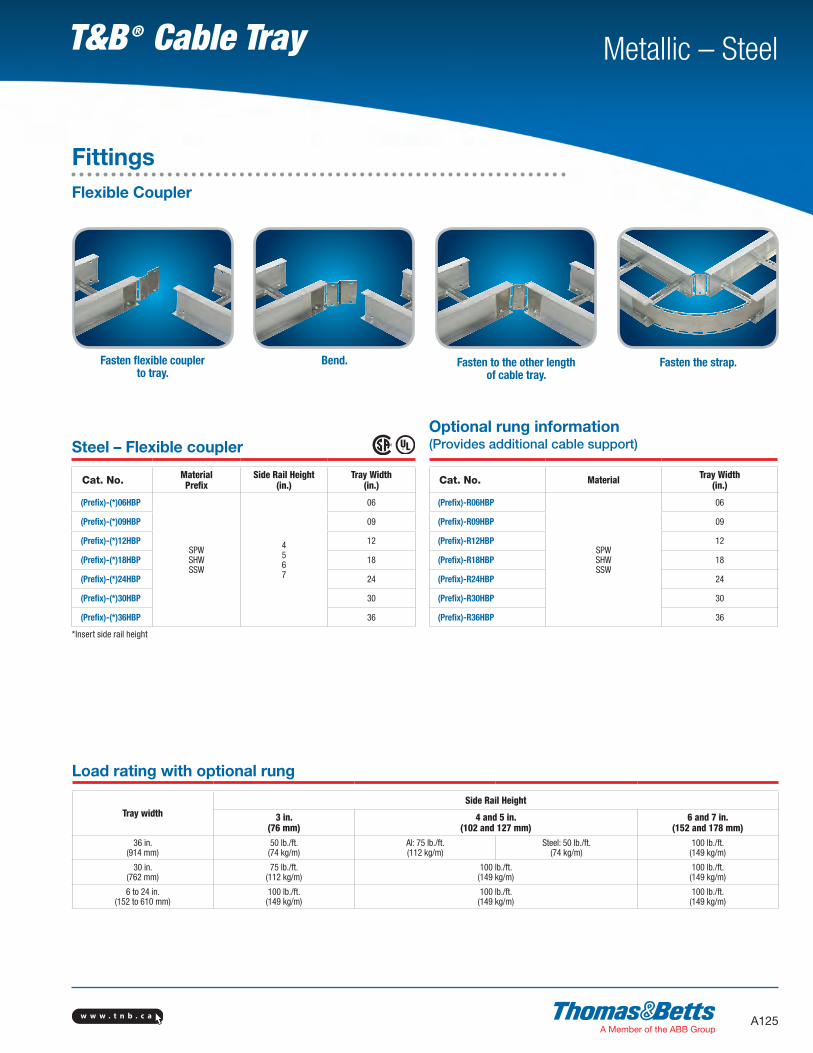
FittingsFlexible Coupler
Introducing our newFlexible CouplerExterior strap provides accurate radius to meet your cable tray design requirements.The flexible coupler provides easy installation without measuring and cutting cable tray side rails. Once installed, the coupler allows for electrical continuity, therefore eliminating the requirement for a bonding jumper.
• Formed ribs provide better cable protection• Fast and easy installation• Meets the electrical continuity requirement of NEMA VE1 & CSA C22.2 No. 126.1
Reduces installation time
No need for a bonding jumper
Flexible and economical alternative to regular AU/AH fitting
w w w . t n b . c a A125
Metallic – SteelT&B ® Cable Tray
FittingsFlexible Coupler
Fasten flexible coupler to tray.
Bend. Fasten to the other length of cable tray.
Fasten the strap.
Steel – Flexible coupler
Cat. No. MaterialPrefix
Side Rail Height (in.)
Tray Width (in.)
(Prefix)-(*)06HBP
SPWSHWSSW
4567
06
(Prefix)-(*)09HBP 09
(Prefix)-(*)12HBP 12
(Prefix)-(*)18HBP 18
(Prefix)-(*)24HBP 24
(Prefix)-(*)30HBP 30
(Prefix)-(*)36HBP 36
*Insert side rail height
Optional rung information (Provides additional cable support)
Cat. No. Material Tray Width (in.)
(Prefix)-R06HBP
SPWSHWSSW
06
(Prefix)-R09HBP 09
(Prefix)-R12HBP 12
(Prefix)-R18HBP 18
(Prefix)-R24HBP 24
(Prefix)-R30HBP 30
(Prefix)-R36HBP 36
Load rating with optional rung
Tray widthSide Rail Height
3 in.(76 mm)
4 and 5 in.(102 and 127 mm)
6 and 7 in.(152 and 178 mm)
36 in.(914 mm)
50 lb./ft.(74 kg/m)
Al: 75 lb./ft.(112 kg/m)
Steel: 50 lb./ft.(74 kg/m)
100 lb./ft.(149 kg/m)
30 in.(762 mm)
75 lb./ft.(112 kg/m)
100 lb./ft.(149 kg/m)
100 lb./ft.(149 kg/m)
6 to 24 in.(152 to 610 mm)
100 lb./ft.(149 kg/m)
100 lb./ft.(149 kg/m)
100 lb./ft.(149 kg/m)
w w w . t n b . c aA126
Metallic – SteelT&B ® Cable Tray
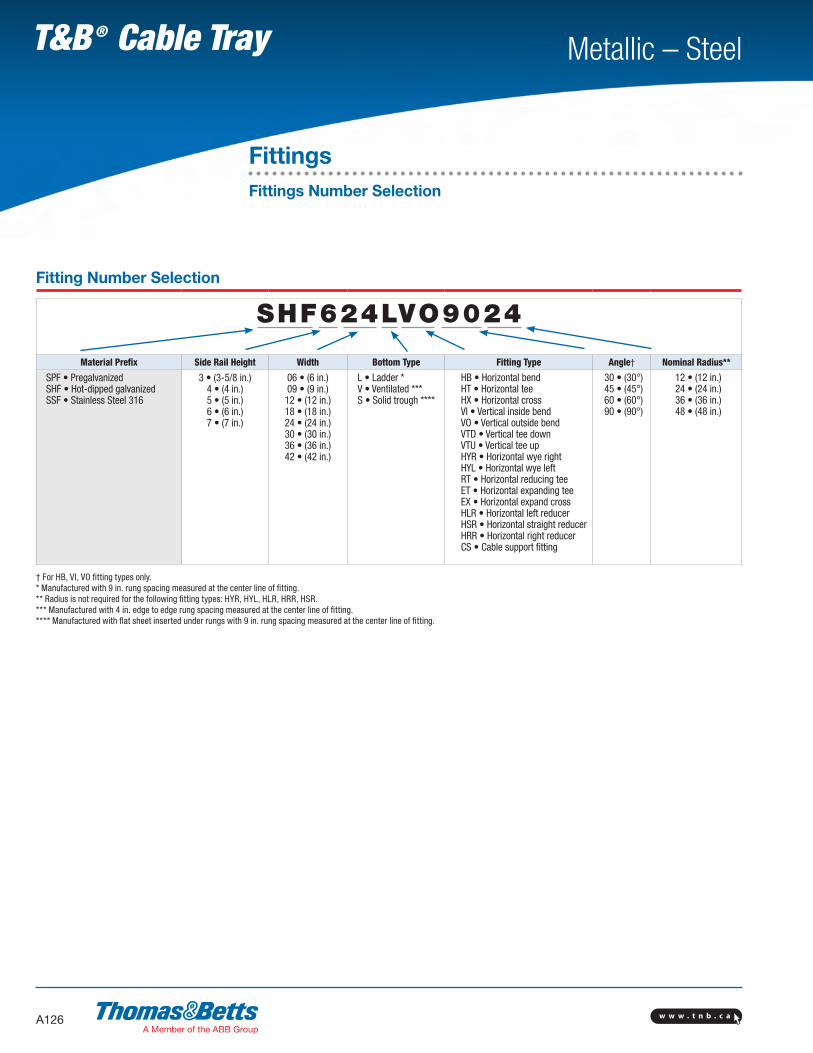
FittingsFittings Number Selection
Fitting Number Selection
SHF624LVO9024
Material Prefix Side Rail Height Width Bottom Type Fitting Type Angle† Nominal Radius**
SPF • PregalvanizedSHF • Hot-dipped galvanizedSSF • Stainless Steel 316
3 • (3-5/8 in.)4 • (4 in.)5 • (5 in.)6 • (6 in.)7 • (7 in.)
06 • (6 in.)09 • (9 in.)12 • (12 in.)18 • (18 in.)24 • (24 in.)30 • (30 in.)36 • (36 in.)42 • (42 in.)
L • Ladder *V • Ventilated ***S • Solid trough ****
HB • Horizontal bendHT • Horizontal teeHX • Horizontal crossVI • Vertical inside bendVO • Vertical outside bendVTD • Vertical tee downVTU • Vertical tee upHYR • Horizontal wye rightHYL • Horizontal wye leftRT • Horizontal reducing teeET • Horizontal expanding teeEX • Horizontal expand crossHLR • Horizontal left reducerHSR • Horizontal straight reducerHRR • Horizontal right reducerCS • Cable support fitting
30 • (30°)45 • (45°)60 • (60°)90 • (90°)
12 • (12 in.)24 • (24 in.)36 • (36 in.)48 • (48 in.)
† For HB, VI, VO fitting types only.* Manufactured with 9 in. rung spacing measured at the center line of fitting.** Radius is not required for the following fitting types: HYR, HYL, HLR, HRR, HSR.*** Manufactured with 4 in. edge to edge rung spacing measured at the center line of fitting.**** Manufactured with flat sheet inserted under rungs with 9 in. rung spacing measured at the center line of fitting.

w w w . t n b . c a A127
Metallic – SteelT&B ® Cable Tray
90º Horizontal BEND
NominalCat. No.
Dimensions
Radius Width X Y
12
6 Prefix(†)-06-(*)-HB90-12 15 15
9 Prefix(†)-09-(*)-HB90-12 16-1/2 16-1/2
12 Prefix(†)-12-(*)-HB90-12 18 18
18 Prefix(†)-18-(*)-HB90-12 21 21
24 Prefix(†)-24-(*)-HB90-12 24 24
30 Prefix(†)-30-(*)-HB90-12 27 27
36 Prefix(†)-36-(*)-HB90-12 30 30
42 Prefix(†)-42-(*)-HB90-12 33 33
24
6 Prefix(†)-06-(*)-HB90-24 27 27
9 Prefix(†)-09-(*)-HB90-24 28-1/2 28-1/2
12 Prefix(†)-12-(*)-HB90-24 30 30
18 Prefix(†)-18-(*)-HB90-24 33 33
24 Prefix(†)-24-(*)-HB90-24 36 36
30 Prefix(†)-30-(*)-HB90-24 39 39
36 Prefix(†)-36-(*)-HB90-24 42 42
42 Prefix(†)-42-(*)-HB90-24 45 45
36
6 Prefix(†)-06-(*)-HB90-36 39 399 Prefix(†)-09-(*)-HB90-36 40-1/2 40-1/212 Prefix(†)-12-(*)-HB90-36 42 4218 Prefix(†)-18-(*)-HB90-36 45 4524 Prefix(†)-24-(*)-HB90-36 48 4830 Prefix(†)-30-(*)-HB90-36 51 5136 Prefix(†)-36-(*)-HB90-36 54 5442 Prefix(†)-42-(*)-HB90-36 57 57
48
6 Prefix(†)-06-(*)-HB90-48 51 519 Prefix(†)-09-(*)-HB90-48 52-1/2 52-1/212 Prefix(†)-12-(*)-HB90-48 54 5418 Prefix(†)-18-(*)-HB90-48 57 5724 Prefix(†)-24-(*)-HB90-48 60 6030 Prefix(†)-30-(*)-HB90-48 63 6336 Prefix(†)-36-(*)-HB90-48 66 6642 Prefix(†)-42-(*)-HB90-48 69 69
60º Horizontal BEND
NominalCat. No.
Dimensions
Radius Width X Y Z
12
6 Prefix(†)-06-(*)-HB60-12 14-7/8 8-5/8 9-15/16
9 Prefix(†)-09-(*)-HB60-12 16-3/16 9-3/8 10-13/16
12 Prefix(†)-12-(*)-HB60-12 17-1/2 10-1/8 11-11/16
18 Prefix(†)-18-(*)-HB60-12 20-1/16 11-5/8 13-3/8
24 Prefix(†)-24-(*)-HB60-12 22-11/16 13-1/8 15-1/8
30 Prefix(†)-30-(*)-HB60-12 25-5/16 14-5/8 16-7/8
36 Prefix(†)-36-(*)-HB60-12 27-7/8 16-1/8 18-9/16
42 Prefix(†)-42-(*)-HB60-12 30-1/2 17-5/8 20-5/16
24
6 Prefix(†)-06-(*)-HB60-24 25-5/16 14-5/8 16-7/8
9 Prefix(†)-09-(*)-HB60-24 26-9/16 15-3/8 17-3/4
12 Prefix(†)-12-(*)-HB60-24 27-7/8 16-1/8 18-9/16
18 Prefix(†)-18-(*)-HB60-24 30-1/2 17-5/8 20-5/16
24 Prefix(†)-24-(*)-HB60-24 33-1/16 19-1/8 22-1/16
30 Prefix(†)-30-(*)-HB60-24 35-11/16 20-5/8 23-13/16
36 Prefix(†)-36-(*)-HB60-24 38-1/4 22-1/8 25-1/2
42 Prefix(†)-42-(*)-HB60-24 40-7/8 23-5/8 27-1/4
36
6 Prefix(†)-06-(*)-HB60-36 35-11/16 20-5/8 23-13/169 Prefix(†)-09-(*)-HB60-36 37 21-3/8 24-5/812 Prefix(†)-12-(*)-HB60-36 38-1/4 22-1/8 25-1/218 Prefix(†)-18-(*)-HB60-36 40-7/8 23-5/8 27-2/824 Prefix(†)-24-(*)-HB60-36 43-1/2 25-1/8 2930 Prefix(†)-30-(*)-HB60-36 46-1/16 26-5/8 30-11/1636 Prefix(†)-36-(*)-HB60-36 48-11/16 28-1/8 32-7/1642 Prefix(†)-42-(*)-HB60-36 51-1/4 29-5/8 34-3/16
48
6 Prefix(†)-06-(*)-HB60-48 46-1/16 26-5/8 30-11/169 Prefix(†)-09-(*)-HB60-48 47-3/8 27-3/8 31-9/1612 Prefix(†)-12-(*)-HB60-48 48-11/16 28-1/8 32-7/1618 Prefix(†)-18-(*)-HB60-48 51-4/16 29-5/8 34-3/1624 Prefix(†)-24-(*)-HB60-48 53-7/8 31-1/8 35-15/1630 Prefix(†)-30-(*)-HB60-48 56-7/16 32-5/8 37-5/836 Prefix(†)-36-(*)-HB60-48 59-1/16 34-1/8 39-3/842 Prefix(†)-42-(*)-HB60-48 61-11/16 35-5/8 41-1/8
Part Numbering System
SHF 4 24 L HB90 12
Selection Guide
Prefix: SPF (Pregalv.), SHF (Hot-Dip), SSF (Stainless Steel)
Inside Tray Widths: 6, 9, 12, 18, 24, 30, 36, 42 Angle: 90o, 60o
Nominal Radius: 12, 24, 36, 48 Bottom Styles: L– Ladder, V– Ventilated, S– SolidSide Rail Heights: 3 in., 4 in., 5 in., 6 in., 7 in.
PrefixSPF, SHF, SSF
Fittingtype
Nominalradius
Width
Side railheight
Bottom style Angle
Fittings90º / 60º Horizontal Bends
(†) Insert side rail height (*) Insert bottom style to complete CAT. NO. Includes 1 pair of splice plates with hardware.

w w w . t n b . c aA128
Metallic – SteelT&B ® Cable Tray
45º Horizontal BEND
NominalCat. No.
Dimensions
Radius Width X Y Z
12
6 Prefix(†)-06-(*)-HB45-12 13-5/8 5-5/8 8
9 Prefix(†)-09-(*)-HB45-12 14-11/16 6-1/16 8-9/16
12 Prefix(†)-12-(*)-HB45-12 15-3/4 6-1/2 9-3/16
18 Prefix(†)-18-(*)-HB45-12 17-7/8 7-3/8 10-7/16
24 Prefix(†)-24-(*)-HB45-12 20 8-1/4 11-11/16
30 Prefix(†)-30-(*)-HB45-12 22-1/16 9-1/8 12-15/16
36 Prefix(†)-36-(*)-HB45-12 24-3/16 10 14-3/16
42 Prefix(†)-42-(*)-HB45-12 26-5/16 10-15/16 15-7/16
24
6 Prefix(†)-06-(*)-HB45-24 22-1/16 9-1/8 12-15/16
9 Prefix(†)-09-(*)-HB45-24 23-1/8 9-9/16 13-9/16
12 Prefix(†)-12-(*)-HB45-24 24-3/16 10 14-3/16
18 Prefix(†)-18-(*)-HB45-24 26-5/16 10-15/16 15-7/16
24 Prefix(†)-24-(*)-HB45-24 28-7/16 11-13/16 16-11/16
30 Prefix(†)-30-(*)-HB45-24 30-9/16 12-11/16 17-15/16
36 Prefix(†)-36-(*)-HB45-24 32-11/16 13-9/16 19-1/8
42 Prefix(†)-42-(*)-HB45-24 34-13/16 14-7/8 20-3/8
36
6 Prefix(†)-06-(*)-HB45-36 30-9/16 12-11/16 17-15/16
9 Prefix(†)-09-(*)-HB45-36 31-5/8 13-1/8 18-9/16
12 Prefix(†)-12-(*)-HB45-36 32-11/16 13-9/16 19-1/8
18 Prefix(†)-18-(*)-HB45-36 34-13/16 14-7/16 20-3/8
24 Prefix(†)-24-(*)-HB45-36 36-15/16 15-5/16 21-5/8
30 Prefix(†)-30-(*)-HB45-36 39-1/16 16-3/16 22-7/8
36 Prefix(†)-36-(*)-HB45-36 41-3/16 17-1/16 24-1/8
42 Prefix(†)-42-(*)-HB45-36 43-5/16 17-15/16 25-3/8
48
6 Prefix(†)-06-(*)-HB45-48 39-1/16 16-3/16 22-7/8
9 Prefix(†)-09-(*)-HB45-48 40-1/8 16-3/8 23-1/2
12 Prefix(†)-12-(*)-HB45-48 41-3/16 17-1/16 24-1/8
18 Prefix(†)-18-(*)-HB45-48 43-5/16 17-15/16 25-3/8
24 Prefix(†)-24-(*)-HB45-48 45-7/16 18-13/16 26-5/8
30 Prefix(†)-30-(*)-HB45-48 47-9/16 19-11/16 27-7/8
36 Prefix(†)-36-(*)-HB45-48 49-11/16 20-9/16 29-1/8
42 Prefix(†)-42-(*)-HB45-48 51-13/16 21-7/16 30-5/16
30º Horizontal BEND
NominalCat. No.
Dimensions
Radius Width X Y Z
12
6 Prefix(†)-06-(*)-HB30-12 11-5/8 3-1/8 6-3/16
9 Prefix(†)-09-(*)-HB30-12 12-3/8 3-5/16 6-5/8
12 Prefix(†)-12-(*)-HB30-12 13-1/2 3-1/2 7
18 Prefix(†)-18-(*)-HB30-12 14-5/8 3-15/16 7-13/16
24 Prefix(†)-24-(*)-HB30-12 16-1/8 4-5/16 8-5/8
30 Prefix(†)-30-(*)-HB30-12 17-5/8 4-11/16 9-7/16
36 Prefix(†)-36-(*)-HB30-12 19-1/8 5-1/8 10-1/4
42 Prefix(†)-42-(*)-HB30-12 20-5/8 5-1/2 11-1/16
24
6 Prefix(†)-06-(*)-HB30-24 17-5/8 4-11/16 9-7/16
9 Prefix(†)-09-(*)-HB30-24 18-3/8 4-15/16 9-13/16
12 Prefix(†)-12-(*)-HB30-24 19-1/8 5-2/16 10-4/16
18 Prefix(†)-18-(*)-HB30-24 20-5/8 5-8/16 11-1/16
24 Prefix(†)-24-(*)-HB30-24 22-1/8 5-15/16 11-13/16
30 Prefix(†)-30-(*)-HB30-24 23-5/8 6-5/16 12-10/16
36 Prefix(†)-36-(*)-HB30-24 25-1/8 6-12/16 13-7/16
42 Prefix(†)-42-(*)-HB30-24 26-5/8 7-1/8 14-1/4
36
6 Prefix(†)-06-(*)-HB30-36 23-5/8 6-5/16 12-5/8
9 Prefix(†)-09-(*)-HB30-36 24-3/8 6-1/2 13-1/16
12 Prefix(†)-12-(*)-HB30-36 25-1/8 6-3/4 13-7/16
18 Prefix(†)-18-(*)-HB30-36 26-5/8 7-1/4 14-1/4
24 Prefix(†)-24-(*)-HB30-36 28-1/8 7-1/2 15-1/16
30 Prefix(†)-30-(*)-HB30-36 29-5/8 7-15/16 15-7/8
36 Prefix(†)-36-(*)-HB30-36 31-1/8 8-5/16 16-11/16
42 Prefix(†)-42-(*)-HB30-36 32-5/8 8-3/4 17-1/2
48
6 Prefix(†)-06-(*)-HB30-48 29-5/8 7-15/16 15-7/8
9 Prefix(†)-09-(*)-HB30-48 30-3/8 8-1/8 16-1/4
12 Prefix(†)-12-(*)-HB30-48 31-1/8 8-5/16 16-11/16
18 Prefix(†)-18-(*)-HB30-48 32-5/8 8-3/4 17-1/2
24 Prefix(†)-24-(*)-HB30-48 34-1/8 9-1/8 18-1/4
30 Prefix(†)-30-(*)-HB30-48 35-5/8 9-9/16 19-1/16
36 Prefix(†)-36-(*)-HB30-48 37-1/8 9-15/16 19-7/8
42 Prefix(†)-42-(*)-HB30-48 38-5/8 10-5/16 20-11/16
Fittings45º / 30º Horizontal Bends
Part Numbering System
SHF 4 24 L HB45 12
Selection Guide
Prefix: SPF (Pregalv.) ,SHF (Hot-Dip) ,SSF (Stainless Steel)
Inside Tray Widths: 6, 9, 12, 18, 24, 30, 36, 42 Angle: 45o, 30o
Nominal Radius: 12, 24, 36, 48 Bottom Styles: L– Ladder, V– Ventilated, S– SolidSide Rail Heights: 3 in., 4 in., 5 in., 6 in., 7 in.
PrefixSPF, SHF, SSF
Fittingtype
Nominalradius
Width
Side railheight
Bottom style Angle
(†) Insert side rail height. (*) Insert bottom style to complete CAT. NO. Includes 1 pair of splice plates with hardware.

w w w . t n b . c a A129
Metallic – SteelT&B ® Cable Tray
FittingsHorizontal Tees, Crosses
Part Numbering System
SHF 4 24 L HT 12
Selection Guide
Prefix: SPF (Pregalv.), SHF (Hot-Dip) ,SSF (Stainless Steel)
Inside Tray Widths: 6, 9, 12, 18, 24, 30, 36, 42 Nominal Radius: 12, 24, 36, 48 Bottom Styles: L– Ladder, V– Ventilated, S– SolidSide Rail Heights: 3 in., 4 in., 5 in., 6 in., 7 in.
PrefixSPF, SHF, SSF
Fittingtype
Nominalradius
Width
Side railheight
Bottom style
Horizontal TEE
NominalCat. No.
Dimensions
Radius Width X Y
12
6 Prefix(†)-06-(*)-HT12 15 30
9 Prefix(†)-09-(*)-HT12 16-1/2 33
12 Prefix(†)-12-(*)-HT12 18 36
18 Prefix(†)-18-(*)-HT12 21 42
24 Prefix(†)-24-(*)-HT12 24 48
30 Prefix(†)-30-(*)-HT12 27 54
36 Prefix(†)-36-(*)-HT12 30 60
42 Prefix(†)-42-(*)-HT12 33 66
24
6 Prefix(†)-06-(*)-HT24 27 54
9 Prefix(†)-09-(*)-HT24 28-1/2 57
12 Prefix(†)-12-(*)-HT24 30 60
18 Prefix(†)-18-(*)-HT24 33 66
24 Prefix(†)-24-(*)-HT24 36 72
30 Prefix(†)-30-(*)-HT24 39 78
36 Prefix(†)-36-(*)-HT24 42 84
42 Prefix(†)-42-(*)-HT24 45 90
36
6 Prefix(†)-06-(*)-HT36 39 78
9 Prefix(†)-09-(*)-HT36 40-1/2 81
12 Prefix(†)-12-(*)-HT36 42 84
18 Prefix(†)-18-(*)-HT36 45 90
24 Prefix(†)-24-(*)-HT36 48 96
30 Prefix(†)-30-(*)-HT36 51 102
36 Prefix(†)-36-(*)-HT36 54 108
42 Prefix(†)-42-(*)-HT36 57 114
48
6 Prefix(†)-06-(*)-HT48 51 102
9 Prefix(†)-09-(*)-HT48 52-1/2 105
12 Prefix(†)-12-(*)-HT48 54 108
18 Prefix(†)-18-(*)-HT48 57 114
24 Prefix(†)-24-(*)-HT48 60 120
30 Prefix(†)-30-(*)-HT48 63 126
36 Prefix(†)-36-(*)-HT48 66 132
42 Prefix(†)-42-(*)-HT48 69 138
Horizontal CROSS
NominalCat. No.
Dimensions
Radius Width X Y
12
6 Prefix(†)-06-(*)-HX12 15 30
9 Prefix(†)-09-(*)-HX12 16-1/2 33
12 Prefix(†)-12-(*)-HX12 18 36
18 Prefix(†)-18-(*)-HX12 21 42
24 Prefix(†)-24-(*)-HX12 24 48
30 Prefix(†)-30-(*)-HX12 27 54
36 Prefix(†)-36-(*)-HX12 30 60
42 Prefix(†)-42-(*)-HX12 33 66
24
6 Prefix(†)-06-(*)-HX24 27 54
9 Prefix(†)-09-(*)-HX24 28-1/2 57
12 Prefix(†)-12-(*)-HX24 30 60
18 Prefix(†)-18-(*)-HX24 33 66
24 Prefix(†)-24-(*)-HX24 36 72
30 Prefix(†)-30-(*)-HX24 39 78
36 Prefix(†)-36-(*)-HX24 42 84
42 Prefix(†)-42-(*)-HX24 45 90
36
6 Prefix(†)-06-(*)-HX36 39 78
9 Prefix(†)-09-(*)-HX36 40-1/2 81
12 Prefix(†)-12-(*)-HX36 42 84
18 Prefix(†)-18-(*)-HX36 45 90
24 Prefix(†)-24-(*)-HX36 48 96
30¥ Prefix(†)-30-(*)-HX36 51 102
36¥ Prefix(†)-36-(*)-HX36 54 108
42¥ Prefix(†)-42-(*)-HX36 57 114
48¥
6 Prefix(†)-06-(*)-HX48 51 102
9 Prefix(†)-09-(*)-HX48 52-1/2 105
12 Prefix(†)-12-(*)-HX48 54 108
18 Prefix(†)-18-(*)-HX48 57 114
24 Prefix(†)-24-(*)-HX48 60 120
30 Prefix(†)-30-(*)-HX48 63 126
36 Prefix(†)-36-(*)-HX48 66 132
42 Prefix(†)-42-(*)-HX48 69 138(†) Insert side rail height. (*) Insert bottom style to complete CAT. NO. Tees include 2 pairs / Crosses include 3 pairs of splice plates with hardware.¥ Shipped with SPW-3/8HXHWK hardware kit.

w w w . t n b . c aA130
Metallic – SteelT&B ® Cable Tray
Horizontal REDUCING TEE — U-Style
WidthsCat. No.
(+) 12 in. Nominal Radius (+) 24 in. Nominal Radius (+) 36 in. Nominal Radius (+) 48 in. Nominal Radius
W1 W2 X Y X Y X Y X Y
42
36 Prefix(†)-4236-(*)-RT(+) 33 60 45 84 57 108 69 132
30 Prefix(†)-4230-(*)-RT(+) 33 54 45 78 57 102 69 126
24 Prefix(†)-4224-(*)-RT(+) 33 48 45 72 57 96 69 120
18 Prefix(†)-4218-(*)-RT(+) 33 42 45 66 57 90 69 114
12 Prefix(†)-4212-(*)-RT(+) 33 36 45 60 57 84 69 108
9 Prefix(†)-4209-(*)-RT(+) 33 33 45 57 57 81 69 105
6 Prefix(†)-4206-(*)-RT(+) 33 30 45 54 57 78 69 102
36
30 Prefix(†)-3630-(*)-RT(+) 30 54 42 78 54 102 66 126
24 Prefix(†)-3624-(*)-RT(+) 30 48 42 72 54 96 66 120
18 Prefix(†)-3618-(*)-RT(+) 30 42 42 66 54 90 66 114
12 Prefix(†)-3612-(*)-RT(+) 30 36 42 60 54 84 66 108
9 Prefix(†)-3609-(*)-RT(+) 30 33 42 57 54 81 66 105
6 Prefix(†)-3606-(*)-RT(+) 30 30 42 54 54 78 66 102
3024 Prefix(†)-3024-(*)-RT(+) 27 48 39 72 51 96 63 120
18 Prefix(†)-3018-(*)-RT(+) 27 42 39 66 51 90 63 114
12 Prefix(†)-3012-(*)-RT(+) 27 36 39 60 51 84 63 108
9 Prefix(†)-3009-(*)-RT(+) 27 33 39 57 51 81 63 105
6 Prefix(†)-3006-(*)-RT(+) 27 30 39 54 51 78 63 102
2418 Prefix(†)-2418-(*)-RT(+) 24 42 36 66 48 90 60 114
12 Prefix(†)-2412-(*)-RT(+) 24 36 36 60 48 84 60 108
9 Prefix(†)-2409-(*)-RT(+) 24 33 36 57 48 81 60 105
6 Prefix(†)-2406-(*)-RT(+) 24 30 36 54 48 78 60 102
1812 Prefix(†)-1812-(*)-RT(+) 21 36 33 60 45 84 57 108
9 Prefix(†)-1809-(*)-RT(+) 21 33 33 57 45 81 57 105
6 Prefix(†)-1806-(*)-RT(+) 21 30 33 54 45 78 57 102
12 9 Prefix(†)-1209-(*)-RT(+) 18 33 30 57 42 81 54 105
6 Prefix(†)-1206-(*)-RT(+) 18 30 30 54 42 78 54 102
9 6 Prefix(†)-0906-(*)-RT(+) 16-1/2 30 28-1/2 54 40-1/2 78 52-1/2 102
(†) Insert side rail height. (*) Insert bottom style to complete CAT. NO. (+) Insert radius (12 in. - 48 in.). Includes 2 pairs of splice plates with hardware.
Part Numbering System
SHF 4 3024 L RT 12
Selection Guide
Prefix: SPF (Pregalv.), SHF (Hot-Dip), SSF (Stainless Steel) Tray Widths W1: 42, 36, 30, 24, 18, 12, 9Tray Widths W2: 36, 30, 24, 18, 12, 9, 6Nominal Radius: 12, 24, 36, 48 Bottom Styles: L– Ladder, V– Ventilated, S– SolidSide Rail Heights: 3 in., 4 in., 5 in., 6 in., 7 in.
PrefixSPF, SHF, SSF
Fittingtype
Nominalradius
Width 1
Side railheight
Bottom style
Width 2
FittingsHorizontal Reducing Tees

w w w . t n b . c a A131
Metallic – SteelT&B ® Cable Tray
Horizontal EXPANDING TEE — U-Style
WidthsCat. No.
(+) 12 in. Nominal Radius (+) 24 in. Nominal Radius (+) 36 in. Nominal Radius (+) 48 in. Nominal Radius
W1 W2 X Y X Y X Y X Y
36 42 Prefix(†)-3642-(*)-ET(+) 30 66 42 90 54 114 66 138
30 36 Prefix(†)-3036-(*)-ET(+) 27 60 39 84 51 108 63 132
42 Prefix(†)-3042-(*)-ET(+) 27 66 39 90 51 114 63 138
2430 Prefix(†)-2430-(*)-ET(+) 24 54 36 78 48 102 60 126
36 Prefix(†)-2436-(*)-ET(+) 24 60 36 84 48 108 60 132
42 Prefix(†)-2442-(*)-ET(+) 24 66 36 90 48 114 60 138
1824 Prefix(†)-1824-(*)-ET(+) 21 48 33 72 45 96 57 120
30 Prefix(†)-1830-(*)-ET(+) 21 54 33 78 45 102 57 126
36 Prefix(†)-1836-(*)-ET(+) 21 60 33 84 45 108 57 132
42 Prefix(†)-1842-(*)-ET(+) 21 66 33 90 45 114 57 138
1218 Prefix(†)-1218-(*)-ET(+) 18 42 30 66 42 90 54 114
24 Prefix(†)-1224-(*)-ET(+) 18 48 30 72 42 96 54 120
30 Prefix(†)-1230-(*)-ET(+) 18 54 30 78 42 102 54 126
36 Prefix(†)-1236-(*)-ET(+) 18 60 30 84 42 108 54 132
42 Prefix(†)-1242-(*)-ET(+) 18 66 30 90 42 114 54 138
9
12 Prefix(†)-0912-(*)-ET(+) 16-1/2 36 28-1/2 60 40-1/2 84 52-1/2 108
18 Prefix(†)-0918-(*)-ET(+) 16-1/2 42 28-1/2 66 40-1/2 90 52-1/2 114
24 Prefix(†)-0924-(*)-ET(+) 16-1/2 48 28-1/2 72 40-1/2 96 52-1/2 120
30 Prefix(†)-0930-(*)-ET(+) 16-1/2 54 28-1/2 78 40-1/2 102 52-1/2 126
36 Prefix(†)-0936-(*)-ET(+) 16-1/2 60 28-1/2 84 40-1/2 108 52-1/2 132
42 Prefix(†)-0942-(*)-ET(+) 16-1/2 66 28-1/2 90 40-1/2 114 52-1/2 138
6
9 Prefix(†)-0609-(*)-ET(+) 15 33 27 57 39 81 51 105
12 Prefix(†)-0612-(*)-ET(+) 15 36 27 60 39 84 51 108
18 Prefix(†)-0618-(*)-ET(+) 15 42 27 66 39 90 51 114
24 Prefix(†)-0624-(*)-ET(+) 15 48 27 72 39 96 51 120
30 Prefix(†)-0630-(*)-ET(+) 15 54 27 78 39 102 51 126
36 Prefix(†)-0636-(*)-ET(+) 15 60 27 84 39 108 51 132
42 Prefix(†)-0636-(*)-ET(+) 15 66 27 90 39 114 51 138
(†) Insert side rail height. (*) Insert bottom style (+) Insert radius (12 in. - 48 in.) to complete CAT. NO. Includes 2 pairs of splice plates with hardware.
Part Numbering System
SHF 4 2430 L ET 12
Selection Guide
Prefix: SPF (Pregalv.), SHF (Hot-Dip), SSF (Stainless Steel) Tray Widths W1: 36, 30, 24, 18, 12, 9, 6Tray Widths W2: 42, 36, 30, 24, 18, 12, 9 Nominal Radius: 12, 24, 36, 48 Bottom Styles: L– Ladder, V– Ventilated, S– SolidSide Rail Heights: 3 in., 4 in., 5 in., 6 in., 7 in.
PrefixSPF, SHF, SSF
Fittingtype
Nominalradius
Width 1
Side railheight
Bottom style
Width 2
FittingsHorizontal Expanding Tees

w w w . t n b . c aA132
Metallic – SteelT&B ® Cable Tray
Part Numbering System
SHF 4 2430 V EX 12
Selection Guide
Prefix: SPF (Pregalv.), SHF (Hot-Dip), SSF (Stainless Steel)
Tray Widths W1: 30, 24, 18, 12, 9, 6Tray Widths W2: 42, 36, 30, 24, 18, 12, 9Nominal Radius: 12, 24, 36, 48 Bottom Styles: L– Ladder, V– Ventilated, S– SolidSide Rail Heights: 3 in., 4 in., 5 in., 6 in., 7 in.
PrefixSPF, SHF, SSF
Fittingtype
Nominalradius
Width 1
Side railheight
Bottom style
Width 2
FittingsHorizontal Expanding Crosses
Horizontal EXPANDING CROSS
WidthsCat. No.
(+) 12 in. Nominal Radius (+) 24 in. Nominal Radius (+) 36 in. Nominal Radius² (+) 48 in. Nominal Radius¹
W1 W2 X Y X Y X Y X Y
36 42 Prefix(†)-3642-(*)-EX(+) 60 66 84 90 108 114 132 138
30 36 Prefix(†)-3036-(*)-EX(+) 54 60 78 84 102 108 126 132
42 Prefix(†)-3042-(*)-EX(+) 54 66 78 90 102 114 126 138
2430 Prefix(†)-2430-(*)-EX(+) 48 54 72 78 96 102 120 126
36 Prefix(†)-2436-(*)-EX(+) 48 60 72 84 96 108 120 132
42 Prefix(†)-2442-(*)-EX(+) 48 66 72 90 96 114 120 138
1824 Prefix(†)-1824-(*)-EX(+) 42 48 66 72 90 96 114 120
30 Prefix(†)-1830-(*)-EX(+) 42 54 66 78 90 102 114 126
36 Prefix(†)-1836-(*)-EX(+) 42 60 66 84 90 108 114 132
42 Prefix(†)-1842-(*)-EX(+) 42 66 66 90 90 114 114 138
1218 Prefix(†)-1218-(*)-EX(+) 36 42 60 66 84 90 108 114
24 Prefix(†)-1224-(*)-EX(+) 36 48 60 72 84 96 108 120
30 Prefix(†)-1230-(*)-EX(+) 36 54 60 78 84 102 108 126
36 Prefix(†)-1236-(*)-EX(+) 36 60 60 84 84 108 108 132
42 Prefix(†)-1242-(*)-EX(+) 36 66 60 90 84 114 108 138
9
12 Prefix(†)-0912-(*)-EX(+) 33 36 57 60 81 84 105 108
18 Prefix(†)-0918-(*)-EX(+) 33 42 57 66 81 90 105 114
24 Prefix(†)-0924-(*)-EX(+) 33 48 57 72 81 96 105 120
30 Prefix(†)-0930-(*)-EX(+) 33 54 57 78 81 102 105 126
36 Prefix(†)-0936-(*)-EX(+) 33 60 57 84 81 108 105 132
42 Prefix(†)-0942-(*)-EX(+) 33 66 57 90 81 114 105 138
6
9 Prefix(†)-0609-(*)-EX(+) 30 33 54 57 78 81 102 105
12 Prefix(†)-0612-(*)-EX(+) 30 36 54 60 78 84 102 108
18 Prefix(†)-0618-(*)-EX(+) 30 42 54 66 78 90 102 114
24 Prefix(†)-0624-(*)-EX(+) 30 48 54 72 78 96 102 120
30 Prefix(†)-0630-(*)-EX(+) 30 54 54 78 78 102 102 126
36 Prefix(†)-0636-(*)-EX(+) 30 60 54 84 78 108 102 132
42 Prefix(†)-0642-(*)-EX(+) 30 66 54 90 78 114 102 138(†) Insert side rail height. (*) Insert bottom (+) Insert radius (12 in. - 48 in.) style to complete CAT. NO. Includes 3 pairs of splice plates with hardware.¹ All 48 in. radius crosses shipped with SPW-3/8HXHWK hardware kit.² All 36 in. radius crosses with width (W1) 30 in. or larger shipped with SPW-3/8HXHWK hardware kit.

w w w . t n b . c a A133
Metallic – SteelT&B ® Cable Tray
Part Numbering System
SHF 4 24 L VI90 12
Selection Guide
Prefix: SPF (Pregalv.), SHF (Hot-Dip), SSF (Stainless Steel) Inside Tray Widths: 6, 9, 12, 18, 24, 30, 36, 42Angle: 90o
Nominal Radius: 12, 24, 36, 48Bottom Styles: L– Ladder, V– Ventilated, S– SolidSide Rail Heights: 3 in., 4 in., 5 in., 6 in., 7 in.
PrefixSPF, SHF, SSF
Fittingtype
Nominalradius
Width
Side railheight
Bottom style Angle
Fittings90º Vertical Bends
90° Vertical BEND Outside Bend Inside Bend
Nominal(+) VO Side Rail (+) VI Side Rail
3-5/8 in. – 7 in. 3-1/2 in. 4 in. 5 in. 6 in. 7 in.
Radius Width Cat. No. X Y X Y X Y X Y X Y X Y
12
6 Prefix(†)-06-(*)-(+)90-12
12 12 15-5/8 15-5/8 16-3/6 16-3/6 17-3/16 17-3/16 18-3/16 18-3/16 19-3/16 19-3/16
9 Prefix(†)-09-(*)-(+)90-1212 Prefix(†)-12-(*)-(+)90-1218 Prefix(†)-18-(*)-(+)90-1224 Prefix(†)-24-(*)-(+)90-1230 Prefix(†)-30-(*)-(+)90-1236 Prefix(†)-36-(*)-(+)90-1242 Prefix(†)-42-(*)-(+)90-12
24
6 Prefix(†)-06-(*)-(+)90-24
24 24 27-5/8 27-5/8 28-3/16 28-3/16 29-3/16 29-3/16 30-3/16 30-3/16 31-3/16 31-3/16
9 Prefix(†)-09-(*)-(+)90-2412 Prefix(†)-12-(*)-(+)90-2418 Prefix(†)-18-(*)-(+)90-2424 Prefix(†)-24-(*)-(+)90-2430 Prefix(†)-30-(*)-(+)90-2436 Prefix(†)-36-(*)-(+)90-2442 Prefix(†)-42-(*)-(+)90-24
36
6 Prefix(†)-06-(*)-(+)90-36
36 36 39-5/8 39-5/8 40-3/16 40-3/16 41-3/16 41-3/16 42-3/16 42-3/16 43-3/16 43-3/16
9 Prefix(†)-09-(*)-(+)90-3612 Prefix(†)-12-(*)-(+)90-3618 Prefix(†)-18-(*)-(+)90-3624 Prefix(†)-24-(*)-(+)90-3630 Prefix(†)-30-(*)-(+)90-3636 Prefix(†)-36-(*)-(+)90-3642 Prefix(†)-42-(*)-(+)90-36
48
6 Prefix(†)-06-(*)-(+)90-48
48 48 51-5/8 51-5/8 52-3/16 52-3/16 53-3/16 53-3/16 54-3/16 54-3/16 55-3/16 55-3/16
9 Prefix(†)-09-(*)-(+)90-4812 Prefix(†)-12-(*)-(+)90-4818 Prefix(†)-18-(*)-(+)90-4824 Prefix(†)-24-(*)-(+)90-4830 Prefix(†)-30-(*)-(+)90-4836 Prefix(†)-36-(*)-(+)90-4842 Prefix(†)-42-(*)-(+)90-48
(†) Insert side rail height. (*) Insert bottom (+) Insert “VO” for vertical outside or “VI” for vertical inside style to complete CAT. NO. Includes 1 pair of splice plates with hardware.

w w w . t n b . c aA134
Metallic – SteelT&B ® Cable Tray
Part Numbering System
SHF 4 24 L VI60 12
Selection Guide
Prefix: SPF (Pregalv.), SHF (Hot-Dip), SSF (Stainless Steel)
Inside Tray Widths: 6, 9, 12, 18, 24, 30, 36, 42 Angle: 60o
Nominal Radius: 12, 24, 36, 48 Bottom Styles: L– Ladder, V– Ventilated, S– SolidSide Rail Heights: 3 in., 4 in., 5 in., 6 in., 7 in.
PrefixSPF, SHF, SSF
Fittingtype
Nominalradius
Width
Side railheight
Bottom style Angle
Fittings60º Vertical Bends
60° Vertical BENDOutside Bend Inside Bend
Nominal(+) VO Side Rail (+) VI Side Rail
3-5/8 in. – 7 in. 3-1/2 in. 4 in. 5 in. 6 in. 7 in.
Radius Width Cat. No. X Y Z X Y Z X Y Z X Y Z X Y Z X Y Z
12
6 Prefix(†)-06-(*)-(+)60-12
10-3/8 6 6-15/16 13-1/2 9-5/8 9 14 10-3/16 9-3/8 14-7/8 11-3/16 9-15/16 15-3/4 12-3/16 10-1/2 16-5/8 13-3/16 11-1/16
9 Prefix(†)-09-(*)-(+)60-1212 Prefix(†)-12-(*)-(+)60-1218 Prefix(†)-18-(*)-(+)60-1224 Prefix(†)-24-(*)-(+)60-1230 Prefix(†)-30-(*)-(+)60-1236 Prefix(†)-36-(*)-(+)60-1242 Prefix(†)-42-(*)-(+)60-12
24
6 Prefix(†)-06-(*)-(+)60-24
20-13/16 12 13-7/8 23-15/16 15-5/8 15-15/16 24-7/16 16-3/16 16-1/4 25-1/4 17-3/16 16-7/8 26-1/8 18-3/16 17-7/16 27 19-3/16 18
9 Prefix(†)-09-(*)-(+)60-2412 Prefix(†)-12-(*)-(+)60-2418 Prefix(†)-18-(*)-(+)60-2424 Prefix(†)-24-(*)-(+)60-2430 Prefix(†)-30-(*)-(+)60-2436 Prefix(†)-36-(*)-(+)60-2442 Prefix(†)-42-(*)-(+)60-24
36
6 Prefix(†)-06-(*)-(+)60-36
31-3/16 18 20-13/16 34-5/16 21-5/8 22-7/8 34-13/16 22-3/4 23-3/16 35-11/16 23-3/16 23-3/4 36-1/2 24-3/16 24-3/8 37-7/16 25-3/16 24-15/16
9 Prefix(†)-09-(*)-(+)60-3612 Prefix(†)-12-(*)-(+)60-3618 Prefix(†)-18-(*)-(+)60-3624 Prefix(†)-24-(*)-(+)60-3630 Prefix(†)-30-(*)-(+)60-3636 Prefix(†)-36-(*)-(+)60-3642 Prefix(†)-42-(*)-(+)60-36
48
6 Prefix(†)-06-(*)-(+)60-48
41-9/16 24 27-11/1644-11/16 27-5/8 29-13/16 45-3/16 28-3/16 30-1/8 46-1/16 29-3/16 30-11/1646-15/16 30-3/16 31-1/8 47-13/16 31-3/16 31-7/8
9 Prefix(†)-09-(*)-(+)60-4812 Prefix(†)-12-(*)-(+)60-4818 Prefix(†)-18-(*)-(+)60-4824 Prefix(†)-24-(*)-(+)60-4830 Prefix(†)-30-(*)-(+)60-4836 Prefix(†)-36-(*)-(+)60-4842 Prefix(†)-42-(*)-(+)60-48
(†) Insert side rail height. (*) Insert bottom (+) Insert “VO” for vertical outside or “VI” for vertical inside style to complete CAT. NO. Includes 1 pair of splice plates with hardware.

w w w . t n b . c a A135
Metallic – SteelT&B ® Cable Tray
Part Numbering System
SHF 4 24 L VI45 12
Selection Guide
Prefix: SPF (Pregalv.), SHF (Hot-Dip), SSF (Stainless Steel)
Inside Tray Widths: 6, 9, 12, 18, 24, 30, 36, 42 Angle: 45o
Nominal Radius: 12, 24, 36, 48 Bottom Styles: L– Ladder, V– Ventilated, S– SolidSide Rail Heights: 3 in., 4 in., 5 in., 6 in., 7 in.
PrefixSPF, SHF, SSF
Fittingtype
Nominalradius
Width
Side railheight Bottom style Angle
Fittings45º Vertical Bends
45o Vertical BENDOutside Bend Inside Bend
Nominal(+) VO Side Rail (+) VI Side Rail
3-5/8 in. – 7 in. 3-1/2 in. 4 in. 5 in. 6 in. 7 in.
Radius Width Cat. No. X Y Z X Y Z X Y Z X Y Z X Y Z X Y Z
12
6 Prefix(†)-06-(*)-(+)45-12
8-1/2 3-1/2 5 11-1/16 7-1/8 6-1/2 11-7/16 7-11/16 6-11/16 12-1/8 8-11/16 7-1/8 12-7/8 9-11/16 7-1/2 13-9/16 10-11/16 7-15/16
9 Prefix(†)-09-(*)-(+)45-1212 Prefix(†)-12-(*)-(+)45-1218 Prefix(†)-18-(*)-(+)45-1224 Prefix(†)-24-(*)-(+)45-1230 Prefix(†)-30-(*)-(+)45-1236 Prefix(†)-36-(*)-(+)45-1242 Prefix(†)-42-(*)-(+)45-12
24
6 Prefix(†)-06-(*)-(+)45-24
17 7 9-15/16 19-1/2 10-5/8 11-7/16 19-15/16 11-3/16 11-11/16 20-5/8 12-3/16 12-1/16 21-3/8 13-3/16 12-1/2 22-1/16 14-3/16 12-15/16
9 Prefix(†)-09-(*)-(+)45-2412 Prefix(†)-12-(*)-(+)45-2418 Prefix(†)-18-(*)-(+)45-2424 Prefix(†)-24-(*)-(+)45-2430 Prefix(†)-30-(*)-(+)45-2436 Prefix(†)-36-(*)-(+)45-2442 Prefix(†)-42-(*)-(+)45-24
36
6 Prefix(†)-06-(*)-(+)45-36
25-7/16 10-9/16 14-15/16 28 14-3/16 16-7/16 28-7/16 14-3/4 16-5/8 29-1/8 15-3/4 17-1/16 29-13/16 16-3/4 17-1/2 30-1/2 17-3/4 17-7/8
9 Prefix(†)-09-(*)-(+)45-3612 Prefix(†)-12-(*)-(+)45-3618 Prefix(†)-18-(*)-(+)45-3624 Prefix(†)-24-(*)-(+)45-3630 Prefix(†)-30-(*)-(+)45-3636 Prefix(†)-36-(*)-(+)45-3642 Prefix(†)-42-(*)-(+)45-36
48
6 Prefix(†)-06-(*)-(+)45-48
33-15/16 14-1/16 19-7/8 36-1/2 17-11/16 21-3/8 36-7/8 18-1/4 21-5/8 37-5/8 19-1/4 22 39-5/16 20-1/4 22-7/16 39 21-1/4 22-7/8
9 Prefix(†)-09-(*)-(+)45-4812 Prefix(†)-12-(*)-(+)45-4818 Prefix(†)-18-(*)-(+)45-4824 Prefix(†)-24-(*)-(+)45-4830 Prefix(†)-30-(*)-(+)45-4836 Prefix(†)-36-(*)-(+)45-4842 Prefix(†)-42-(*)-(+)45-48
(†) Insert side rail height. (*) Insert bottom (+) Insert “VO” for vertical outside or “VI” for vertical inside style to complete CAT. NO. Includes 1 pair of splice plates with hardware.
1.750’’

w w w . t n b . c aA136
Metallic – SteelT&B ® Cable Tray
Fittings30º Vertical Bends
30° Vertical BENDOutside Bend Inside Bend
Nominal(+) VO Side Rail (+) VI Side Rail
3-5/8 – 7 in. 3-1/2 in. 4 in. 5 in. 6 in. 7 in.
Radius Width Cat. No. X Y Z X Y Z X Y Z X Y Z X Y Z X Y Z
12
6 Prefix(†)-06-(*)-(+)30-12
6 1-5/8 3-3/16 7-13/16 5-1/4 4-3/16 8-1/16 15-13/16 4-5/16 8-9/16 6-13/16 4-5/8 9-1/16 7-13/16 4-7/8 9-9/16 8-13/16 5-1/8
9 Prefix(†)-09-(*)-(+)30-1212 Prefix(†)-12-(*)-(+)30-1218 Prefix(†)-18-(*)-(+)30-1224 Prefix(†)-24-(*)-(+)30-1230 Prefix(†)-30-(*)-(+)30-1236 Prefix(†)-36-(*)-(+)30-1242 Prefix(†)-42-(*)-(+)30-12
24
6 Prefix(†)-06-(*)-(+)30-24
12 3-3/16 6-7/16 13-13/16 6-13/16 7-3/8 14-1/16 7-3/8 7-9/16 14-9/16 8-3/8 7-13/16 15-1/16 9-3/8 8-1/16 15-9/16 10-3/8 8-3/8
9 Prefix(†)-09-(*)-(+)30-2412 Prefix(†)-12-(*)-(+)30-2418 Prefix(†)-18-(*)-(+)30-2424 Prefix(†)-24-(*)-(+)30-2430 Prefix(†)-30-(*)-(+)30-2436 Prefix(†)-36-(*)-(+)30-2442 Prefix(†)-42-(*)-(+)30-24
36
6 Prefix(†)-06-(*)-(+)30-36
18 4-13/16 9-5/8 19-13/16 8-7/16 10-5/8 20-1/16 9 10-3/4 20-1/16 10 11-1/16 21-1/16 11 11-5/16 21-9/16 12 11-9/16
9 Prefix(†)-09-(*)-(+)30-3612 Prefix(†)-12-(*)-(+)30-3618 Prefix(†)-18-(*)-(+)30-3624 Prefix(†)-24-(*)-(+)30-3630 Prefix(†)-30-(*)-(+)30-3636 Prefix(†)-36-(*)-(+)30-3642 Prefix(†)-42-(*)-(+)30-36
48
6 Prefix(†)-06-(*)-(+)30-48
24 6-7/16 12-7/8 25-13/16 10-1/16 13-13/16 26-1/16 10-5/8 14 26-9/16 11-5/8 14-1/4 27-1/16 12-5/8 14-1/2 27-9/16 13-5/8 14-13/16
9 Prefix(†)-09-(*)-(+)30-4812 Prefix(†)-12-(*)-(+)30-4818 Prefix(†)-18-(*)-(+)30-4824 Prefix(†)-24-(*)-(+)30-4830 Prefix(†)-30-(*)-(+)30-4836 Prefix(†)-36-(*)-(+)30-4842 Prefix(†)-42-(*)-(+)30-48
(†) Insert side rail height. (*) Insert bottom (+) Insert “VO” for vertical outside or “VI” for vertical inside style to complete CAT. NO. Includes 1 pair of splice plates with hardware.
Part Numbering System
SHF 4 24 L VI30 12
Selection Guide
Prefix: SPF (Pregalv.), SHF (Hot-Dip), SSF (Stainless Steel)
Inside Tray Widths: 6, 9, 12, 18, 24, 30, 36, 42 Angle: 30o
Nominal Radius: 12, 24, 36, 48 Bottom Styles: L– Ladder, V– Ventilated, S– SolidSide Rail Heights: 3 in., 4 in., 5 in., 6 in., 7 in.
PrefixSPF, SHF, SSF
Fittingtype
Nominalradius
Width
Side railheight
Bottom style Angle

w w w . t n b . c a A137
Metallic – SteelT&B ® Cable Tray
Part Numbering System
SHF-6-36-24-L-HLR
Selection Guide
Prefix: SPF (Pregalv.), SHF (Hot-Dip), SSF (Stainless Steel)
Tray Widths W1: 42, 36, 30, 24, 18, 12, 9Tray Widths W2: 36, 30, 24, 18, 12, 9, 6Bottom Styles: L– Ladder, V– Ventilated, S– SolidSide Rail Heights: 3 in., 4 in., 5 in., 6 in., 7 in.
PrefixSPF, SHF, SSF
Fittingtype
Width 1
Side railheight
Bottom style
Width 2
FittingsReducers
Horizontal REDUCERSOffset Reducer - Right Reducer - Straight Offset Reducer - Left
Widths Left Reducer Straight Reducer (Concentric) Right Reducer
W1 W2 Cat. No. Dim. X Cat. No. Dim. X Cat. No. Dim. X
42
36 Prefix(†)-42-36-(*)-HLR 15-716 Prefix(†)-42-36-(*)-HSR 13-3/4 Prefix(†)-42-36-(*)-HRR 15-716
30 Prefix(†)-42-30-(*)-HLR 18-15/16 Prefix(†)-42-30-(*)-HSR 15-7/16 Prefix(†)-42-30-(*)-HRR 18-15/16
24 Prefix(†)-42-24-(*)-HLR 22-3/8 Prefix(†)-42-24-(*)-HSR 17-3/16 Prefix(†)-42-24-(*)-HRR 22-3/8
18 Prefix(†)-42-18-(*)-HLR 25-7/8 Prefix(†)-42-18-(*)-HSR 18-5/16 Prefix(†)-42-18-(*)-HRR 25-7/8
12 Prefix(†)-42-12-(*)-HLR 29-5/16 Prefix(†)-42-12-(*)-HSR 20-5/8 Prefix(†)-42-12-(*)-HRR 29-5/16
9 Prefix(†)-42-09-(*)-HLR 31-1/16 Prefix(†)-42-09-(*)-HSR 21-1/2 Prefix(†)-42-09-(*)-HRR 31-1/16
6 Prefix(†)-42-06-(*)-HLR 32-3/4 Prefix(†)-42-06-(*)-HSR 22-3/8 Prefix(†)-42-06-(*)-HRR 32-3/4
36
30 Prefix(†)-36-30-(*)-HLR 15-7/16 Prefix(†)-36-30-(*)-HSR 13-3/4 Prefix(†)-36-30-(*)-HRR 15-7/16
24 Prefix(†)-36-24-(*)-HLR 18-15/16 Prefix(†)-36-24-(*)-HSR 15-7/16 Prefix(†)-36-24-(*)-HRR 18-15/16
18 Prefix(†)-36-18-(*)-HLR 22-3/8 Prefix(†)-36-18-(*)-HSR 17-3/8 Prefix(†)-36-18-(*)-HRR 22-3/8
12 Prefix(†)-36-12-(*)-HLR 25-7/8 Prefix(†)-36-12-(*)-HSR 18-5/16 Prefix(†)-36-12-(*)-HRR 25-7/8
9 Prefix(†)-36-09-(*)-HLR 27-9/16 Prefix(†)-36-09-(*)-HSR 19-13/16 Prefix(†)-36-09-(*)-HRR 27-9/16
6 Prefix(†)-36-06-(*)-HLR 29-5/16 Prefix(†)-36-06-(*)-HSR 20-11/16 Prefix(†)-36-06-(*)-HRR 29-5/16
3024 Prefix(†)-30-24-(*)-HLR 15-7/16 Prefix(†)-30-24-(*)-HSR 13-3/4 Prefix(†)-30-24-(*)-HRR 15-7/16
18 Prefix(†)-30-18-(*)-HLR 18-15/16 Prefix(†)-30-18-(*)-HSR 15-7/16 Prefix(†)-30-18-(*)-HRR 18-15/16
12 Prefix(†)-30-12-(*)-HLR 22-3/8 Prefix(†)-30-12-(*)-HSR 17-3/16 Prefix(†)-30-12-(*)-HRR 22-3/8
9 Prefix(†)-30-09-(*)-HLR 24-1/8 Prefix(†)-30-09-(*)-HSR 18-1/16 Prefix(†)-30-09-(*)-HRR 24-1/8
6 Prefix(†)-30-06-(*)-HLR 25-7/8 Prefix(†)-30-06-(*)-HSR 18-15/16 Prefix(†)-30-06-(*)-HRR 25-7/8
2418 Prefix(†)-24-18-(*)-HLR 15-7/16 Prefix(†)-24-18-(*)-HSR 13-3/4 Prefix(†)-24-18-(*)-HRR 15-7/16
12 Prefix(†)-24-12-(*)-HLR 18-15/16 Prefix(†)-24-12-(*)-HSR 15-7/16 Prefix(†)-24-12-(*)-HRR 18-15/16
9 Prefix(†)-24-09-(*)-HLR 20-11/16 Prefix(†)-24-09-(*)-HSR 16-5/16 Prefix(†)-24-09-(*)-HRR 20-11/16
6 Prefix(†)-24-06-(*)-HLR 22-3/8 Prefix(†)-24-06-(*)-HSR 17-3/16 Prefix(†)-24-06-(*)-HRR 22-3/8
1812 Prefix(†)-18-12-(*)-HLR 15-7/16 Prefix(†)-18-12-(*)-HSR 13-3/4 Prefix(†)-18-12-(*)-HRR 15-7/16
9 Prefix(†)-18-09-(*)-HLR 17-3/16 Prefix(†)-18-09-(*)-HSR 14-5/8 Prefix(†)-18-09-(*)-HRR 17-3/16
6 Prefix(†)-18-06-(*)-HLR 18-15/16 Prefix(†)-18-06-(*)-HSR 15-7/16 Prefix(†)-18-06-(*)-HRR 18-15/16
12 9 Prefix(†)-12-09-(*)-HLR 13-3/4 Prefix(†)-12-09-(*)-HSR 12-7/8 Prefix(†)-12-09-(*)-HRR 13-3/4
6 Prefix(†)-12-06-(*)-HLR 15-7/16 Prefix(†)-12-06-(*)-HSR 13-3/4 Prefix(†)-12-06-(*)-HRR 15-7/16
9 6 Prefix(†)-09-06-(*)-HLR 13-3/4 Prefix(†)-09-06-(*)-HSR 12-7/8 Prefix(†)-09-06-(*)-HRR 13-3/4
(†) Insert side rail height. (*) Insert bottom style to complete CAT. NO. Includes 1 pair of splice plates with hardware.

w w w . t n b . c aA138
Metallic – SteelT&B ® Cable Tray
Part Numbering System
SHF-6-36-L-HYL
Selection Guide
Prefix: SPF (Pregalv.), SHF (Hot-Dip), SSF (Stainless Steel)
Inside Tray Widths: 6, 9, 12, 18, 24, 30, 36, 42 Bottom Styles: L– Ladder, V– Ventilated, S– SolidSide Rail Heights: 3 in., 4 in., 5 in., 6 in., 7 in.Prefix
SPF, SHF, SSFFittingtype
Width
Side railheight
Bottom style
Fittings45º Horizontal Wyes
45° Horizontal WYE — U-StyleLeft Hand Wye Right Hand Wye
Width Left Hand Wye Cat. No.
Right Hand Wye Cat. No.
Dimensions
X Y Z
6 Prefix(†)-06-(*)-HYL Prefix(†)-06-(*)-HYR 18-5/16 14-13/16 12-7/16
9 Prefix(†)-09-(*)-HYL Prefix(†)-09-(*)-HYR 22-1/2 19-15/16 15-7/16
12 Prefix(†)-12-(*)-HYL Prefix(†)-12-(*)-HYR 26-3/4 25 18-7/16
18 Prefix(†)-18-(*)-HYL Prefix(†)-18-(*)-HYR 35-1/4 35-1/4 24-7/16
24 Prefix(†)-24-(*)-HYL Prefix(†)-24-(*)-HYR 43-1/2 45-1/2 30-7/16
30 Prefix(†)-30-(*)-HYL Prefix(†)-30-(*)-HYR 52-1/4 55-3/4 36-7/16
36 Prefix(†)-36-(*)-HYL Prefix(†)-36-(*)-HYR 60-11/16 66 42-7/16
42 Prefix(†)-42-(*)-HYL Prefix(†)-42-(*)-HYR 69-3/16 76-1/4 45-7/16
(†) Insert side rail height. (*) Insert bottom style to complete CAT. NO. Includes 1 pair of splice plates with hardware.

w w w . t n b . c a A139
Metallic – SteelT&B ® Cable Tray
Part Numbering System
SHF 4 24 L VTD 12
Selection Guide
Prefix: SPF (Pregalv.), SHF (Hot-Dip), SSF (Stainless Steel)
Inside Tray Widths: 6, 9, 12, 18, 24, 30, 36, 42 Nominal Radius: 12, 24, 36, 48 Bottom Styles: L– Ladder, V– Ventilated, S– SolidSide Rail Heights: 3 in., 4 in., 5 in., 6 in., 7 in.
PrefixSPF, SHF, SSF
Fittingtype
Nominalradius
Width
Side railheight
Bottom style
FittingsVertical Tees Up / Down
Vertical Tee Up/DownOutside Bend Inside Bend
Nominal Vertical Tee Up
Vertical Tee Down
Side Rail Height ‘‘H”
3-5/8 in. 4 in. 5 in. 6 in. 7 in.
Radius Width Cat. No. Cat. No. X Y X Y X Y X Y X Y
12
6 Prefix(†)-06-(*)-VTU12 Prefix(†)-06-(*)-VTD12
13-13/16 27-5/8 14-1/8 28-3/16 14-5/8 29-3/16 15-1/8 30-3/16 15-5/8 31-3/16
9 Prefix(†)-09-(*)-VTU12 Prefix(†)-09-(*)-VTD1212 Prefix(†)-12-(*)-VTU12 Prefix(†)-12-(*)-VTD1218 Prefix(†)-18-(*)-VTU12 Prefix(†)-18-(*)-VTD1224 Prefix(†)-24-(*)-VTU12 Prefix(†)-24-(*)-VTD1230 Prefix(†)-30-(*)-VTU12 Prefix(†)-30-(*)-VTD1236 Prefix(†)-36-(*)-VTU12 Prefix(†)-36-(*)-VTD1242 Prefix(†)-42-(*)-VTU12 Prefix(†)-42-(*)-VTD12
24
6 Prefix(†)-06-(*)-VTU24 Prefix(†)-06-(*)-VTD24
25-13/16 51-5/8 26-1/8 52-3/16 26-5/8 53-3/16 27-1/8 54-3/16 27-5/8 55-3/16
9 Prefix(†)-09-(*)-VTU24 Prefix(†)-09-(*)-VTD2412 Prefix(†)-12-(*)-VTU24 Prefix(†)-12-(*)-VTD2418 Prefix(†)-18-(*)-VTU24 Prefix(†)-18-(*)-VTD2424 Prefix(†)-24-(*)-VTU24 Prefix(†)-24-(*)-VTD2430 Prefix(†)-30-(*)-VTU24 Prefix(†)-30-(*)-VTD2436 Prefix(†)-36-(*)-VTU24 Prefix(†)-36-(*)-VTD2442 Prefix(†)-42-(*)-VTU24 Prefix(†)-42-(*)-VTD24
36
6 Prefix(†)-06-(*)-VTU36 Prefix(†)-06-(*)-VTD36
37-13/16 75-5/8 38-1/8 76-3/16 38-5/8 77-3/16 39-1/8 78-3/16 39-5/8 79-3/16
9 Prefix(†)-09-(*)-VTU36 Prefix(†)-09-(*)-VTD3612 Prefix(†)-12-(*)-VTU36 Prefix(†)-12-(*)-VTD3618 Prefix(†)-18-(*)-VTU36 Prefix(†)-18-(*)-VTD3624 Prefix(†)-24-(*)-VTU36 Prefix(†)-24-(*)-VTD3630 Prefix(†)-30-(*)-VTU36 Prefix(†)-30-(*)-VTD3636 Prefix(†)-36-(*)-VTU36 Prefix(†)-36-(*)-VTD3642 Prefix(†)-42-(*)-VTU36 Prefix(†)-42-(*)-VTD36
48
6 Prefix(†)-06-(*)-VTU48 Prefix(†)-06-(*)-VTD48
49-13/16 99-5/8 50-1/8 100-3/16 50-5/8 101-3/16 51-1/8 102-3/16 51-5/8 103-3/16
9 Prefix(†)-09-(*)-VTU48 Prefix(†)-09-(*)-VTD4812 Prefix(†)-12-(*)-VTU48 Prefix(†)-12-(*)-VTD4818 Prefix(†)-18-(*)-VTU48 Prefix(†)-18-(*)-VTD4824 Prefix(†)-24-(*)-VTU48 Prefix(†)-24-(*)-VTD4830 Prefix(†)-30-(*)-VTU48 Prefix(†)-30-(*)-VTD4836 Prefix(†)-36-(*)-VTU48 Prefix(†)-36-(*)-VTD4842 Prefix(†)-42-(*)-VTU48 Prefix(†)-42-(*)-VTD48
(†) Insert side rail height. (*) Insert bottom style to complete CAT. NO. Includes 1 pair of splice plates with hardware.

w w w . t n b . c aA140
Metallic – SteelT&B ® Cable Tray
Part Numbering System
SHF 4 24 L CS 12
Selection Guide
Prefix: SPF (Pregalv.), SHF (Hot-Dip), SSF (Stainless Steel)
Inside Tray Widths: 6, 9, 12, 18, 24, 30, 36, 42 Nominal Radius: 12, 24, 36, 48 Bottom Styles: L– Ladder, V– Ventilated, S– SolidSide Rail Heights: 3 in., 4 in., 5 in., 6 in., 7 in.
PrefixSPF, SHF, SSF
Fittingtype
Width
Side railheight Bottom
style
Nominalradius
FittingsCable Support
Horizontal EXPANDING CROSS
NominalSide Rail Height ‘‘H”
3-5/8 in. 4 in. 5 in. 6 in. 7 in.Radius Width Cat. No. X
12
6 Prefix(†)-06-(*)-CS12
15-5/8 16-3/16 17-3/16 18-3/16 19-3/16
9 Prefix(†)-09-(*)-CS1212 Prefix(†)-12-(*)-CS1218 Prefix(†)-18-(*)-CS1224 Prefix(†)-24-(*)-CS1230 Prefix(†)-30-(*)-CS1236 Prefix(†)-36-(*)-CS1242 Prefix(†)-42-(*)-CS12
24
6 Prefix(†)-06-(*)-CS24
27-5/8 28-3/16 29-3/16 30-3/16 31-3/16
9 Prefix(†)-09-(*)-CS2412 Prefix(†)-12-(*)-CS2418 Prefix(†)-18-(*)-CS2424 Prefix(†)-24-(*)-CS2430 Prefix(†)-30-(*)-CS2436 Prefix(†)-36-(*)-CS2442 Prefix(†)-42-(*)-CS24
36
6 Prefix(†)-06-(*)-CS36
39-5/8 40-3/16 41-3/16 42-3/16 43-3/16
9 Prefix(†)-09-(*)-CS3612 Prefix(†)-12-(*)-CS3618 Prefix(†)-18-(*)-CS3624 Prefix(†)-24-(*)-CS3630 Prefix(†)-30-(*)-CS3636 Prefix(†)-36-(*)-CS3642 Prefix(†)-42-(*)-CS36
48
6 Prefix(†)-06-(*)-CS48
51-5/8 52-3/16 53-3/16 54-3/16 55-3/16
9 Prefix(†)-09-(*)-CS4812 Prefix(†)-12-(*)-CS4818 Prefix(†)-18-(*)-CS4824 Prefix(†)-24-(*)-CS4830 Prefix(†)-30-(*)-CS4836 Prefix(†)-36-(*)-CS4842 Prefix(†)-42-(*)-CS48
(†) Insert side rail height. (*) Insert bottom style to complete CAT. NO. Includes 1 pair of splice plates with hardware.

w w w . t n b . c a A141
Metallic – SteelT&B ® Cable Tray
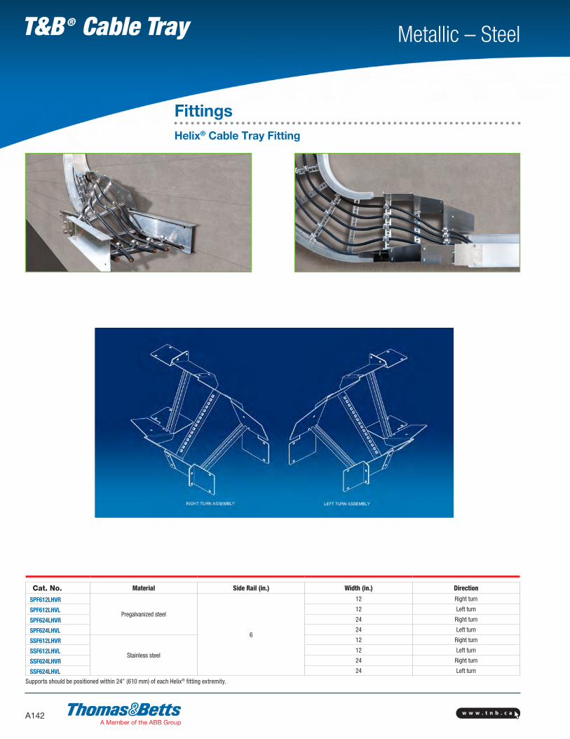
FittingsHelix® Cable Tray Fitting
Go from horizontal to vertical, maximum cable protection, minimum space.Making transitions from horizontal to vertical cable tray runs has never been easier or more efficient. The latest evolution in cable tray fittings, the Helix® fitting assembly was developed specifically for use in confined areas. It allows installers to transition from horizontal to vertical surfaces in less time, using significantly less space. • Enables installation close to walls and other surfaces,
eliminating need for distance• Provides enhanced cable protection in confined spaces• Secures cables within fitting for clean, organized cable runs
The Helix® cable tray fitting. Efficiency is in its DNA.
w w w . t n b . c aA142
Metallic – SteelT&B ® Cable Tray
FittingsHelix® Cable Tray Fitting
Cat. No. Material Side Rail (in.) Width (in.) Direction
SPF612LHVR
Pregalvanized steel
6
12 Right turn
SPF612LHVL 12 Left turn
SPF624LHVR 24 Right turn
SPF624LHVL 24 Left turn
SSF612LHVR
Stainless steel
12 Right turn
SSF612LHVL 12 Left turn
SSF624LHVR 24 Right turn
SSF624LHVL 24 Left turn
Supports should be positioned within 24” (610 mm) of each Helix® fitting extremity.

w w w . t n b . c a A143
Metallic – SteelT&B ® Cable Tray
Solid CoversThese covers provide maximum mechanical protection for cables with limited heat build up. Solid covers are available with or without flange. Flanged covers have 1/2 in. flange.
Cover mounting hardware must be ordered separately.
Ventilated Flanged CoversThis design offers excellent mechanical protection while allowing heat produced by cables to dissipate.
Cover mounting hardware must be ordered separately.
Peaked Flanged CoversPeaked covers offer mechanical protection plus prevent accumulation of liquid on the cover. Peaked covers have 15° rise at the peak. Cover mounting hardware must be ordered separately.
Solid Flanged Solid Non-Flanged
Ventilated Flanged
Tray CoversTray covers are available for all classes of tray. They should be installed where falling objects may damage cables or where a vertical tray run is accessible by pedestrian or vehicular traffic.
Outside cable tray runs should be covered with a peaked flanged cover to protect cable from the elements and excess build up of snow and ice.
Peaked Flanged
Covers

w w w . t n b . c aA144
Metallic – SteelT&B ® Cable Tray
Covers
Straight Cover Number Selection
(SPW12)SNC-3
Material Prefix Width Type Length
SPW • Pregalvanized SHW • Hot-dipped galvanized* SSW • Stainless steel 316
06 • (6 in.)09 • (9 in.)12 • (12 in.)18 • (18 in.)24 • (24 in.)30 • (30 in.)36 • (36 in.)42 • (42 in.)
SNC • Solid non-flanged coverSFC • Solid flanged coverVFC • Ventilated flanged coverPFC • Peaked flanged cover **
72 • (72 in.)3 • (3 m)
* Hot-Dipped Covers only available in 72 in. and 1500 mm lengths.
Fitting Cover Number Selection
(SPW12)SNCHB9024
Material Prefix Width Cover Type Fitting Type Degree* Nominal Radius
SPW • Pregalvanized SHW • Hot-dipped galvanized SSW • Stainless steel 316
06 • (6 in.)09 • (9 in.)12 • (12 in.)18 • (18 in.)24 • (24 in.)30 • (30 in.)36 • (36 in.)42 • (42 in.)
SNC • Solid non-flanged coverSFC • Solid flanged coverVFC • Ventilated flanged cover
HB • Horizontal bendVI • Vertical inside bendHT • Horizontal teeHX • Horizontal crossVTU • Vertical tee upHYR • Horizontal wye rightHYL • Horizontal wye left
30 • (30º) 45 • (45º) 60 • (60º) 90 • (90º)
12 • (12 in.)24 • (24 in.)36 • (36 in.)48 • (48 in.)
* Required for HB & VI only.

w w w . t n b . c a A145
Metallic – SteelT&B ® Cable Tray
Covers
Fitting Cover Number Selection (cont’d)
(SPW1812)SNCRT12
Material Prefix Width 1 Width 2 Cover Type Fitting Type Radius*
SPW • Pregalvanized SHW • Hot-dipped galvanized SSW • Stainless steel 316
06 • (6 in.)09 • (9 in.)12 • (12 in.)18 • (18 in.)24 • (24 in.)30 • (30 in.)36 • (36 in.)42 • (42 in.)
06 • (6 in.)09 • (9 in.)12 • (12 in.)18 • (18 in.)24 • (24 in.)30 • (30 in.)36 • (36 in.)42 • (42 in.)
SNC • Solid non-flanged coverSFC • Solid flanged coverVFC • Ventilated flanged cover
RT • Horizontal reduce teeET • Horizontal expand tee EX • Horizontal expand tee & reduce crossHSR • Horizontal straight reducer HLR • Horizontal left reducer HRR • Horizontal right reducer
12 •(12 in.)24 •(24 in.)36 •(36 in.)48 •(48 in.)
* Radius not required for HSR, HLR, HRR.
Fitting Cover Number Selection
(SPW412)SNCVO9024
Material Prefix Side Rail Height Width Cover Type Fitting Type Degree* Nominal Radius
SPW • Pregalvanized SHW • Hot-dipped galvanizedSSW • Stainless steel 316
3 • (3-5/8 in.)4 • (4 in.)5 • (5 in.)6 • (6 in.)7 • (7 in.)
06 • (6 in.)09 • (9 in.)12 • (12 in.)18 • (18 in.)24 • (24 in.)30 • (30 in.)36 • (36 in.)42 • (42 in.)
SNC • Solid non-flanged coverSFC • Solid flanged coverVFC • Ventilated flanged cover
VO • Vertical outside bendVTD • Vertical tee downCS • Cable support fitting
30 • (30°)45 • (45°)60 • (60°)90 • (90°)
12 • (12 in.)24 • (24 in.)36 • (36 in.)48 • (48 in.)
* Required for VO only.

w w w . t n b . c aA146
Metallic – SteelT&B ® Cable Tray
Steel Number Selection
SSW-6-24-PFC-VO-90-24
Material Prefix Side Rail Height Width Cover Type Fitting Type Degree Nominal Radius
SHW • Hot-dipped galvanizedSSW • Stainless steel 316
4 • (4 in.)5 • (5 in.)6 • (6 in.)7 • (7 in.)
06 • (6 in.)09 • (9 in.)12 • (12 in.)18 • (18 in.)24 • (24 in.)30 • (30 in.)36 • (36 in.)42 • (42 in.)
PFC • Peaked flanged coverPVC • Peaked vented flanged cover
VO • Vertical outside bend 30 • (30°)45 • (45°)60 • (60°)90 • (90°)
12 • (12 in.)24 • (24 in.)36 • (36 in.)48 • (48 in.)
Note: Pregalvanized not available.
Steel Number Selection
SHW-24-PFC-HT-24
Material Prefix Width Cover Type Fitting Type Nominal Radius
SHW • Hot-dipped galvanizedSSW • Stainless steel 316
06 • (6 in.)09 • (9 in.)12 • (12 in.)18 • (18 in.)24 • (24 in.)30 • (30 in.)36 • (36 in.)42 • (42 in.)
PFC • Peaked flanged coverPVC • Peaked vented flanged cover
HT • Horizontal tee 12 •(12 in.)24 •(24 in.)36 •(36 in.)48 •(48 in.)
Note: Pregalvanized not available.
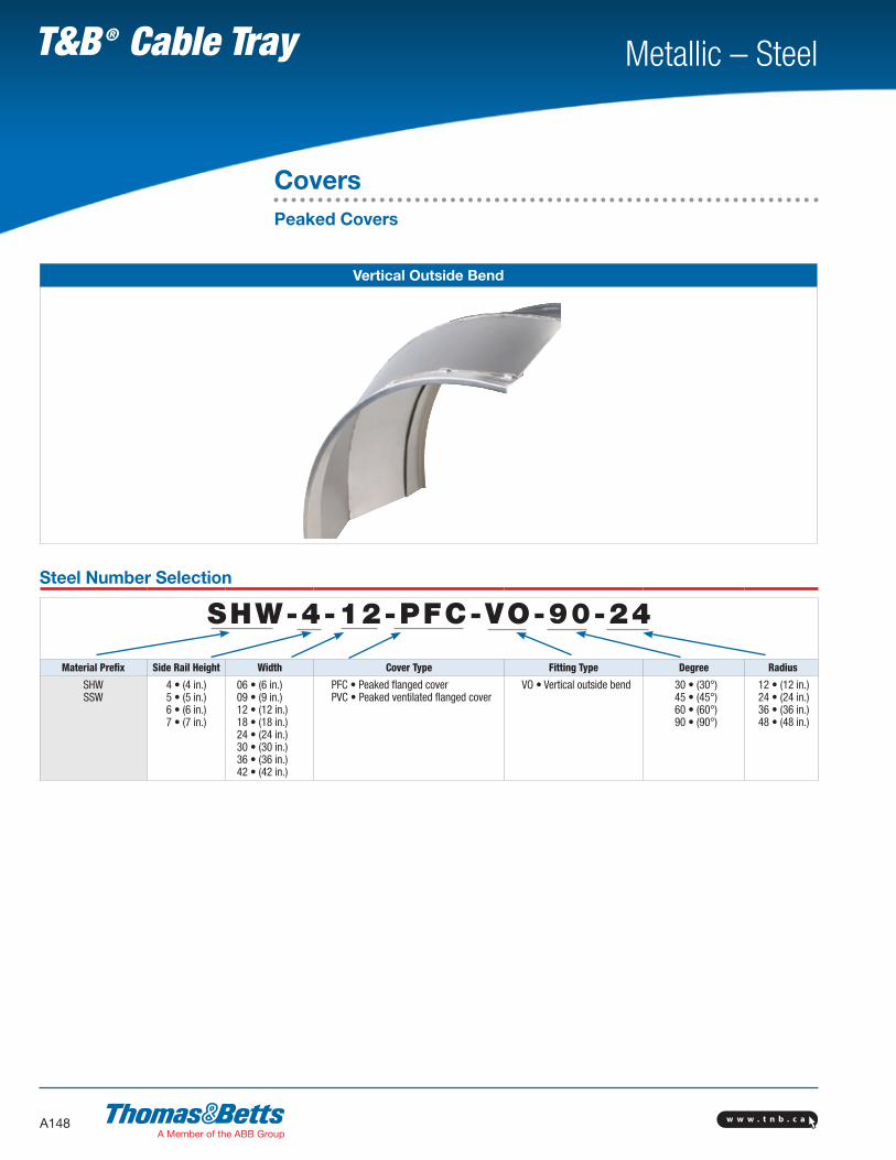
CoversPeaked Covers
Steel Number Selection
SHW-24-PFC-HB-90-24
Material Prefix Width Cover Type Fitting Type Degree Nominal Radius
SHW • Hot-dipped galvanizedSSW • Stainless steel 316
06 • (6 in.)09 • (9 in.)12 • (12 in.)18 • (18 in.)24 • (24 in.)30 • (30 in.)36 • (36 in.)42 • (42 in.)
PFC • Peaked flanged coverPVC • Peaked vented flanged cover
HB • Horizontal bendVI • Vertical inside bend
30 • (30º) 45 • (45º) 60 • (60º) 90 • (90º)
12 • (12 in.)24 • (24 in.)36 • (36 in.)48 • (48 in.)
Note: Pregalvanized not available.

w w w . t n b . c a A147
Metallic – SteelT&B ® Cable Tray
Horizontal Bend
Steel Number Selection
SHW-12-PFC-HB-90-24
Material Prefix Width Cover Type Fitting Type Degree Radius
SHWSSW
06 • (6 in.)09 • (9 in.)12 • (12 in.)18 • (18 in.)24 • (24 in.)30 • (30 in.)36 • (36 in.)42 • (42 in.)
PFC • Peaked flanged coverPVC • Peaked ventilated flanged cover
HB • Horizontal bendVI • Vertical inside bend
30 • (30°)45 • (45°)60 • (60°)90 • (90°)
12 • (12 in.)24 • (24 in.)36 • (36 in.)48 • (48 in.)
Note: Pregalvanized not available.
CoversPeaked Covers
Horizontal Bend / Vertical Inside Bend
w w w . t n b . c aA148
Metallic – SteelT&B ® Cable Tray
Vertical Outside Bend
Steel Number Selection
SHW-4-12-PFC-VO-90-24
Material Prefix Side Rail Height Width Cover Type Fitting Type Degree Radius
SHWSSW
4 • (4 in.)5 • (5 in.)6 • (6 in.)7 • (7 in.)
06 • (6 in.)09 • (9 in.)12 • (12 in.)18 • (18 in.)24 • (24 in.)30 • (30 in.)36 • (36 in.)42 • (42 in.)
PFC • Peaked flanged coverPVC • Peaked ventilated flanged cover
VO • Vertical outside bend 30 • (30°)45 • (45°)60 • (60°)90 • (90°)
12 • (12 in.)24 • (24 in.)36 • (36 in.)48 • (48 in.)
CoversPeaked Covers

w w w . t n b . c a A149
Metallic – SteelT&B ® Cable Tray
Horizontal Tee
Steel Number Selection
SHW-12-PFC-HT-24
Material Prefix Width Cover Type Fitting Type Radius
SHWSSW
06 • (6 in.)09 • (9 in.)12 • (12 in.)18 • (18 in.)24 • (24 in.)30 • (30 in.)36 • (36 in.)42 • (42 in.)
PFC • Peaked flanged coverPVC • Peaked ventilated flanged cover
HT • Horizontal tee 12 • (12 in.)24 • (24 in.)36 • (36 in.)48 • (48 in.)
CoversPeaked Covers

w w w . t n b . c aA150
Metallic – SteelT&B ® Cable Tray
CoversAccessories For Covers
Quantity of Standard Cover Clamps Required
Straight section (6 ft.) 4 pcs.
Straight section (12 ft./ 3 m) 6 pcs.
Horizontal and vertical bends 4 pcs.
Tees 6 pcs.
Crosses 8 pcs.
Note: When using the Heavy-Duty Cover Clamp, only half the quantity of pieces are required.
Raised Cover Clamp
Cat. No. Cover Offset (in.)* Material Prefix
SPW(*)RCC1 SPW
SSW2
(*) Insert cover offset.
Designed to raise cover above tray for added ventilation.
Peaked End Cap
Cat. No. Width (in.) Material Prefix
SPW(*)PECSHW(*)PECSSW(*)PEC
06
SPW SHWSSW
09
12
18
24
30
36
42
Used for transition between peaked covers to straight covers. (*) Insert width

w w w . t n b . c a A151
Metallic – SteelT&B ® Cable Tray
CoversAccessories For Covers
Cover Clamp
Cat. No. Material Prefix Side Rail Height (in.)
(Prefix)-3-SCC(Prefix)-4-SCC(Prefix)-5-SCC(Prefix)-6-SCC(Prefix)-7-SCC
SHWSPW SSW
3
4
5
6
7
Rigid indoor cover clamp for flat and flanged covers.
Heavy-Duty Cover Clamp
Wrap around design offers added protection for rugged applications and outdoor conditions.
Hardware included.
Cat. No. Material Prefix Tray Width (in.) Side Rail Height (in.)
(Prefix)-3-(*)-HCC(Prefix)-4-(*)-HCC(Prefix)-5-(*)-HCC(Prefix)-6-(*)-HCC(Prefix)-7-(*)-HCC
SPW SHW SSW
06
34567
09
12
18
24
30
36
42
(*) Insert tray width
Heavy-Duty Peaked Cover Clamp
Wrap around design formed to fit peaked cover for outdoor applications.
Hardware included.
Cat. No. Material Prefix Tray Width (in.) Side Rail Height (in.)
(Prefix)-3-(*)-HPC(Prefix)-4-(*)-HPC(Prefix)-5-(*)-HPC(Prefix)-6-(*)-HPC(Prefix)-7-(*)-HPC
SPW SHW SSW
06
34567
09
12
18
24
30
36
42
(*) Insert tray width
Cover Joint Strip
Strip used for joining covers end to end.
Cat. No. Material Tray Width (in.)
ABW-(*)-PCS Plastic
06
09
12
18
24
30
36
42
(*) Insert tray width
w w w . t n b . c aA152
Metallic – SteelT&B ® Cable Tray
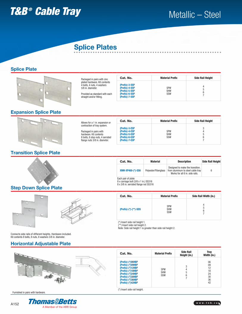
Splice Plates
Splice Plate
Packaged in pairs with zinc plated hardware. Kit contents 4 bolts, 4 nuts, 4 washers 3/8 in. diameter.
Provided as standard with each straight and/or fitting.
Cat. No. Material Prefix Side Rail Height
(Prefix)-3-SSP(Prefix)-4-SSP(Prefix)-5-SSP(Prefix)-6-SSP(Prefix)-7-SSP
SPW SHW SSW
4567
Expansion Splice Plate
Allows for a 1 in. expansion or contraction of tray system.
Packaged in pairs with hardware. Kit contents 8 bolts, 8 stop nuts, 4 serrated flange nuts 3/8 in. diameter.
Cat. No. Material Prefix Side Rail Height
(Prefix)-3-ESP(Prefix)-4-ESP(Prefix)-5-ESP(Prefix)-6-ESP(Prefix)-7-ESP
SPW SHW SSW
34567
Transition Splice Plate
Cat. No. Material Description Side Rail Height
XNM-XP400-(*)-SS6 Polyester/FiberglassDesigned to make the transition. from aluminum to steel cable tray
Works for all 6 in. side rails.6
Step Down Splice Plate
Cat. No. Material Prefix Side Rail Width (in.)
(Prefix)-(*)-(**)-SDSSPW SHW SSW
4567
(*) Insert side rail height 1. (**) Insert side rail height 2. Note: Side rail height 1 is greater than side rail height 2.
Connects side rails of different heights. Hardware included. Kit contents 8 bolts, 8 nuts, 8 washers 3/8 in. diameter.
Horizontal Adjustable Plate
Cat. No. Material Prefix Side RailHeight (in.)
Tray Width (in.)
(Prefix)-(*)06HBP(Prefix)-(*)09HBP(Prefix)-(*)12HBP(Prefix)-(*)18HBP(Prefix)-(*)24HBP(Prefix)-(*)30HBP(Prefix)-(*)36HBP(Prefix)-(*)42HBP
SPWSHWSSW
34567
0609121824303642
Furnished in pairs with hardware.(*) Insert side rail height.
Each pair of plate:8 x carriage bolt (3/8 x 1 in.) SS316 8 x 3/8 in. serrated flange nut SS316

w w w . t n b . c a A153
Metallic – SteelT&B ® Cable Tray
Splice Plates
Vertical Adjustable Plate
Cat. No. Material Prefix Side Rail Height (in.)
(Prefix)-3-VSP
SPW SHW SSW
34567
(Prefix)-4-VSP
(Prefix)-5-VSP
(Prefix)-6-VSP
(Prefix)-7-VSP
Hinged vertical plates provide maximum flexibility for changes in elevation. Packaged in pairs with hardware.
Branch Pivot Connectors
Cat. No. Material Prefix Side Rail Height (in.)
(Prefix)-3-BPC
SPW SHW SSW
34567
(Prefix)-4-BPC
(Prefix)-5-BPC
(Prefix)-6-BPC
(Prefix)-7-BPC
Allows cables to run from one tray level to another.
Box to Tray Plates
Cat. No. Material Prefix Side Rail Height (in.)
(Prefix)-3-BSP
SPW SHW SSW
34567
(Prefix)-4-BSP
(Prefix)-5-BSP
(Prefix)-6-BSP
(Prefix)-7-BSP
Designed to secure tray to electrical panels or boxes, walls or end supports.Packaged in pairs with hardware.

w w w . t n b . c aA154
Metallic – SteelT&B ® Cable Tray
StraightOffset
Splice Plates
Closure End Plate
Cat. No. Material Prefix Side Rail Height (in.)
(Prefix)-3-(*)-CEP(Prefix)-4-(*)-CEP(Prefix)-5-(*)-CEP(Prefix)-6-(*)-CEP(Prefix)-7-(*)-CEP
SPW SHW SSW
3
4
5
6
7
Provides closure for any tray end. Hardware included. (*) Insert tray width
Reducing Splice Plate
Cat. No. Material Prefix Side Rail Height (in.)
(Prefix)-3-(*)RSP(Prefix)-4-(*)RSP(Prefix)-5-(*)RSP(Prefix)-6-(*)RSP(Prefix)-7-(*)RSP
SPW SHW SSW
3
4
5
6
7
Used in pairs to provide a straight reduction or used with a standard splice plate for an offset reduction. One per package with hardware.
*Note: For offset reduction: Insert width to be reduced. For straight reduction: Insert 1/2 width to be reduced (2 required). Example: SPW-503-RSP = 3 in. offset reducer
Super-Duty Splice Plate TM
Cat. No. Material Prefix Side Rail Height (in.)
(Prefix)-4-SDP(Prefix)-5-SDP(Prefix)-6-SDP(Prefix)-7-SDP
SPW SHW SSW
4
5
6
7
ADDITIONAL SUPPORTS PER NEMA STANDARD INSTALLATION
NO ADDITIONAL SUPPORTS NEEDEDWITH SUPER-DUTY SPLICE PLATE™
Comes complete with 16 bolts, 8 stop nuts, 8 nuts, 8 nylon, washers 3/8 diameter required, for either expansion or mid-span splicing.
High-strength design enables reduction of supports recommended for NEMA standard installations at the expansion joint, significantly reducing material and labour costs.
Unique reinforced design eliminates the need to drill and install additional hardware on the flange, saving installation time.
0.6 m 0.6 m
Expansion Splice Plate
75% Span
25% Span
Span
StandardSplice Plate25% Span

w w w . t n b . c a A155
Metallic – SteelT&B ® Cable Tray
Drop-Out
Cat. No. Material Prefix Tray Width (in.)
(Prefix)-(*)-DO(Prefix)-(*)-DOS +
SPW SHW SSW
06
09
12
18
24
30
36
42
Designed to provide a smooth radius surface at any position on the tray or trough bottom. Drop outs are easily attached using hardware provided. Standard radius = 4 in.
(*) Insert tray width + DOS = is for solid tray.
Wall Penetration Sleeve
Cat. No. Material Prefix Tray Width (in.) Side Rail Height (in.)
(Prefix)-(*)-(**)-WPSSPW SHW SSW
06 3
09 4
12 5
18 6
24 7
30
36
42
Designed to pass through walls and fire walls. Hardware included.Note: not fire rated. Fire stop not included.
(*) Insert side rail height. (**) Insert tray width
Frame Type Tray to Box Plate
Designed to secure tray to electrical enclosures and panels.
Hardware included.
Cat. No. Material Prefix Tray Width (in.) Side Rail Height (in.)
(Prefix)-(*)-(**)-FBPSPW SHW SSW
06 3
09 4
12 5
18 6
24 7
30
36
42
(*) Insert side rail height. (**) Insert tray width
Nylon Expansion Pad
Allows for thermal expansion and contraction of cable trays over supports.
Cat. No. Material
ABW-NSP Natural nylon
Sold with cover
Cable Protection
w w w . t n b . c aA156
Metallic – SteelT&B ® Cable Tray
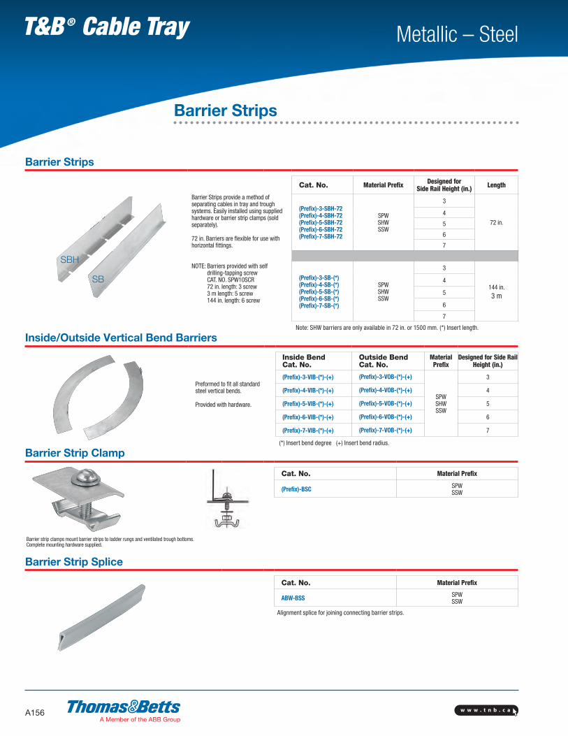
Barrier Strips
Barrier Strips provide a method of separating cables in tray and trough systems. Easily installed using supplied hardware or barrier strip clamps (sold separately).
72 in. Barriers are flexible for use with horizontal fittings.
NOTE: Barriers provided with self drilling-tapping screw CAT. NO. SPW10SCR 72 in. length: 3 screw 3 m length: 5 screw 144 in. length: 6 screw
Cat. No. Material Prefix Designed for Side Rail Height (in.) Length
(Prefix)-3-SBH-72(Prefix)-4-SBH-72(Prefix)-5-SBH-72(Prefix)-6-SBH-72(Prefix)-7-SBH-72
SPWSHWSSW
3
72 in.
4
5
6
7
(Prefix)-3-SB-(*)(Prefix)-4-SB-(*)(Prefix)-5-SB-(*)(Prefix)-6-SB-(*)(Prefix)-7-SB-(*)
SPWSHWSSW
3
144 in. 3 m
4
5
6
7
Note: SHW barriers are only available in 72 in. or 1500 mm. (*) Insert length.
Inside/Outside Vertical Bend Barriers
Preformed to fit all standard steel vertical bends.
Provided with hardware.
Inside Bend Cat. No.
Outside Bend Cat. No.
Material Prefix
Designed for Side Rail Height (in.)
(Prefix)-3-VIB-(*)-(+) (Prefix)-3-VOB-(*)-(+)
SPWSHWSSW
3
(Prefix)-4-VIB-(*)-(+) (Prefix)-4-VOB-(*)-(+) 4
(Prefix)-5-VIB-(*)-(+) (Prefix)-5-VOB-(*)-(+) 5
(Prefix)-6-VIB-(*)-(+) (Prefix)-6-VOB-(*)-(+) 6
(Prefix)-7-VIB-(*)-(+) (Prefix)-7-VOB-(*)-(+) 7
(*) Insert bend degree (+) Insert bend radius.
Barrier Strip Clamp
Cat. No. Material Prefix
(Prefix)-BSC SPWSSW
Barrier strip clamps mount barrier strips to ladder rungs and ventilated trough bottoms.Complete mounting hardware supplied.
Barrier Strip Splice
Cat. No. Material Prefix
ABW-BSS SPWSSW
Alignment splice for joining connecting barrier strips.
SBH
SB
Barrier Strips

w w w . t n b . c a A157
Metallic – SteelT&B ® Cable Tray
Combination Hold Down / Expansion Clamp
Cat. No. Material Prefix
(Prefix)-HECSPW SHW SSW
Order 3/8 in. hardware separately.
Cat. No. Material Prefix
(Prefix)-HEC-HDWSPW SHW SSW
Note: HDW is supplied with 1 bolt, 1 channel nut 1/4 in. diameter.
Steel Tray Hardware
Square shoulder self-positioning carriage bolt.
Cat. No. Material Description
SPW-1/4-CB
Zinc plated steel
1/4 in. carriage bolt
SPW-3/8-CB 3/8 in. carriage bolt
SPW-1/4-HN 1/4 in. serrated flange hex. nut
SPW-3/8-HN 3/8 in. hex. nut
SPW3/8HWK* Hardware kit
SPW-3/8HXHWK** Hardware kit 3/8 in. for large radius crosses
SSW-3/8-CB
316 Stainless
3/8 in. carriage bolt
SSW-3/8-HN 3/8 in. hex. nut
SSW38HWK* 316 Stainless steel hardware kit
SSW-3/8HXHWK** Hardware kit 3/8 in. for large radius crosses
* Contains 8 nuts and 8 bolts.**Contains 6 bolts, 6 nuts and 6 washers.
Clamps and Hardware
Hold down clamp Expansion guide
Cable Tray Combo Clamps
Cat. No. Material Hardware size (in.)
SPWCHGC Pregalvanized steel
3/8SHWCHGC Hot dip galvanized steel
SSWCHGC 316 Stainless
Order 3/8 in. hardware separately.
Cat. No. Material Hardware size (in.)
SPWCHGC-HDW Pregalvanized steel
3/8SHWCHGC-HDW Hot dip galvanized steel
SSWCHGC-HDW 316 Stainless
* Hardware supplied: 1 bolt and 1 springless strut nut 3/8 diameter.
Clamp position on cable tray Guide position on cable tray

w w w . t n b . c aA158
Metallic – SteelT&B ® Cable Tray
Self-drilling – tapping screw
Cat. No. Material Description
SPW-10-SCR Zinc plated steel Self-drilling – tapping screw
SSW-10-SCR Stainless steel Self-drilling – tapping screw
Hold Down Clamp
Cat. No. Material Prefix Side Rail Height (in.)
(Prefix)-3-HDC
SPWSHWSSW
3
(Prefix)-4-HDC 4
(Prefix)-5-HDC 5
(Prefix)-6-HDC 6
(Prefix)-7-HDC 7
Note: Hardware included. Kit contains 1 bolt and 1 channel nut.
Hold Down Clamp
Cat. No. Type Material Design Load
SPWHDCS Single Pregalvanized
800 lb./pairSHWHDCS Single Hot-dipped galvanized
SSWHDCS Single Stainless steel 316
SPWHDCD Double Pregalvanized
1500 lb./pairSHWHDCD Double Hot-dipped galvanized
SSWHDCD Double Stainless steel 316
Conduit Clamp
Cat. No. Type Material
PU100CC 1
Pregalvanized
PU125CC 1-1/4
PU150CC 1-1/2
PU200CC 2
PU250CC 2-1/2
PU300CC 3
PU400CC 4
Clamps and Hardware
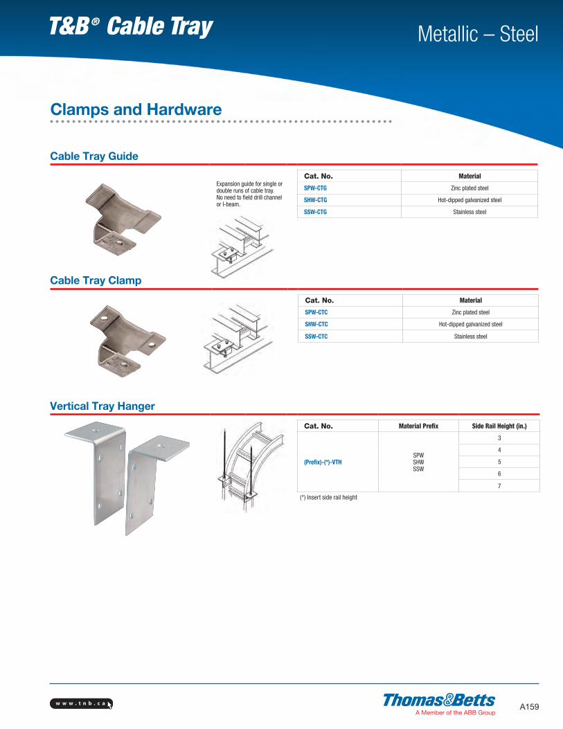
w w w . t n b . c a A159
Metallic – SteelT&B ® Cable Tray
Cable Tray Guide
Expansion guide for single or double runs of cable tray.No need to field drill channel or I-beam.
Cat. No. Material
SPW-CTG Zinc plated steel
SHW-CTG Hot-dipped galvanized steel
SSW-CTG Stainless steel
Cable Tray Clamp
Cat. No. Material
SPW-CTC Zinc plated steel
SHW-CTC Hot-dipped galvanized steel
SSW-CTC Stainless steel
Vertical Tray Hanger
Cat. No. Material Prefix Side Rail Height (in.)
(Prefix)-(*)-VTHSPWSHWSSW
3
4
5
6
7
(*) Insert side rail height
Clamps and Hardware