
Laboratory 9 - Usage of DC- and servo-motors -...
9
Laboratory 9 - Usage of DC- and servo-motors The current laboratory describes the usage of DC and servomotors 1. DC motors Figure 1. Digilent DC Motor Classical DC motors are converting electrical energy in machine work. The rotation speed of the motor is proportional with the voltage applied on the motors’ terminals, while the rotation direction depends on the voltage polarity. The Digilent DC motor incorporates also a rotation speed reduction mechanism (1:19 or 1:53) in order to increase the provided torque and sensors for measuring the rotation speed and direction (“quadrature encoder”). Due to the high current required to spin the shaft of the motor, it cannot be powered/connected directly to the digital pins of a microcontroller. The control signals and the power circuit should be separated using an “H-bridge”. H-bridges are containing 4 switches (usually transistors), numbered S1, S2, S3 and S4 (figure 2) Figure 2. H-bridge: S1-S4 are the switches, M is the DC motor.
Transcript of Laboratory 9 - Usage of DC- and servo-motors -...

Laboratory 9 - Usage of DC- and servo-motors
The current laboratory describes the usage of DC and servomotors
1. DC motors
Figure 1. Digilent DC Motor
Classical DC motors are converting electrical energy in machine work. The rotation speed of the
motor is proportional with the voltage applied on the motors’ terminals, while the rotation direction
depends on the voltage polarity. The Digilent DC motor incorporates also a rotation speed reduction
mechanism (1:19 or 1:53) in order to increase the provided torque and sensors for measuring the
rotation speed and direction (“quadrature encoder”).
Due to the high current required to spin the shaft of the motor, it cannot be powered/connected directly
to the digital pins of a microcontroller. The control signals and the power circuit should be separated
using an “H-bridge”. H-bridges are containing 4 switches (usually transistors), numbered S1, S2, S3
and S4 (figure 2)
Figure 2. H-bridge: S1-S4 are the switches, M is the DC motor.

The H-bridge name comes from the schematic above. The switches on one diagonal (S1 and S4) are
connected to a common control signal “A”, while the switches on the second diagonal (S3 and S2)
are connected to a common control signal “B”. A and B signal are exclusive (should be active only
on at a time, otherwise the power supply is short-circuited), the activation of one or another
determines a change in the rotation direction. For that purpose the Digilent HB5 H-bridge combines
the 2 signals in the form of “Enable” and “DIRection” signals:
EN – starts the spinning process
DIR – sets the rotation direction
The two allowed states of the H-bridge switches are presented in figure 3. By opening switches S1
and S4 the motor will spin in one direction, while opening S3 and S2 the motor will spin in the
opposite direction.
Figure 3. Possible states of the H-bridge switches.
For the current laboratory work the PmodHB5 H-bridge manufactured by Digilent will be used:
Figure 4. Pmod HB5 conected la a Digilent DC motor.
The PmodHB5 incorporates an H bridge that provides a maximum 2A current and can control a DC
motor with a maximum 12V supply voltage. It provides 2 additional pins (SA, SB) for measuring the
rotation speed and direction („quadrature encoder”).

Figure 5. Pmod HB5 pins.
The H bridge will use 2 different power supplies: J1 will be used to power the control and feedback
circuits using the VCC and GND pins from the Arduino board. For the power circuit, an external
DC power source will b connected to connector J3 (GND to the “-“ pin of the external DC power
source and VM to the “+“ pin of the external DC power source). The external DC power source
can be a DC power supply or a battery pack.
The connection of the PmodHB5 with the Arduino board is shown in figure 6:
Figure 6. Connection of the PmodHB5 and DC motor with the Arduino board
Example 1 – Usage of a DC motor with Arduino:

The example bellow shows the rotation speed variation. The rotation speed is controlled by the
average voltage applied on the DC which can be changed using the PWM technique applied on the
EN pin.
int DIR = 7;
int EN = 9;
bool currentDir = 0;
int currentSpeed = 0;
void setup()
{
pinMode(DIR, OUTPUT);
pinMode(EN, OUTPUT);
// set motor to stopped state
analogWrite(EN, 0);
delay(5);
// set direction to 0
digitalWrite(DIR, LOW); // dir = 0
delay(5);
}
void loop()
{
for (int i = 0; i < 255; i += 5) // accelerate
{
analogWrite(EN, i);
delay(10);
}
for (int i = 255; i > 0; i -= 5) // decelerate
{
analogWrite(EN, i);
delay(10);
}
delay(1500);
}
Note: it is forbidden to change the direction (DIR) while EN is “high” (you can damage the H-
bridge). To change the direction the motor should be stopped (EN=0), wait for 1 .. 5 ms, change
the direction, wait again and turn on the motor

2. Servo-motors
In order to control the amount of rotation a servo or stepper motor should be used. In the following
the servo motors usage will be exemplified.
A servo motor has 3 wires: VCC (red), GND (black or brown) and a signal pin (other colors) – see
figure 7:
Figure 7 - Servo-motors wiring/coding options.
Normally a servo-motor would not rotate continuously, but instead it will turn in one direction or
another with an angle proportional to the average voltage applied. The rotation angle (average
voltage) can be controlled using the PWM technique
The easiest way to control the servos can be done using the “Servo” library. With the Arduino Mega
board up to 48 servos can be controlled (if more than 12 servos are used, the library will deactivate
PWM function on pins 11 and 12)
Note: servos require a considerable amount of power. To drive more than 2 servos, use a
separate power supply (not from the +5V of the Arduino). Only connect the GNDs (of the
Arduino and of the external power supplies) together.
The Servo library methods are presented bellow:
servo.attach(pin) / servo.attach(pin, min, max) – attach the servo variable to a pin
• servo: a variable of type Servo
• pin: the number of the pin that the servo is attached to
• min (optional): the pulse width, in microseconds, corresponding to the minimum (0-degree)
angle on the servo (defaults to 544)
• max (optional): the pulse width, in microseconds, corresponding to the maximum (180-
degree) angle on the servo (defaults to 2400)
servo.detach() - detach the Servo variable from its pin.
boolean val servo.attached() - check whether the Servo variable is attached to a pin. Returns value
is true / false
servo.write(angle) - writes a value (0 .. 180) to the servo, controlling the shaft accordingly:
• standard servo set the angle of the shaft [deg] moving it to that orientation.
• continuous rotation servo set the speed of the servo (0: full speed in one direction; 180:
full speed in the other; 90: no movement)
int val = servo.read() - read the current angle of the servo (the value passed to the last call to
write()). Val - angle of the servo, from 0 to 180 degrees.
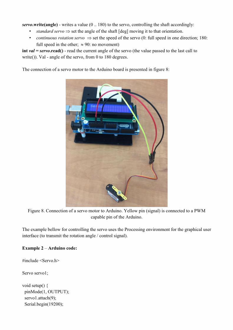
The connection of a servo motor to the Arduino board is presented in figure 8:
Figure 8. Connection of a servo motor to Arduino. Yellow pin (signal) is connected to a PWM
capable pin of the Arduino.
The example bellow for controlling the servo uses the Processing environment for the graphical user
interface (to transmit the rotation angle / control signal).
Example 2 – Arduino code:
#include <Servo.h>
Servo servo1;
void setup() {
pinMode(1, OUTPUT);
servo1.attach(9);
Serial.begin(19200);

}
void loop() {
static int v = 0;
if (Serial.available()) {
char ch = Serial.read();
switch (ch) {
case '0'...'9':
v = v * 10 + ch - '0';
if (v == 0)
v = 0;
break;
case 's':
servo1.write(v);
v = 0;
break;
}
}
}
Example 2 – Processing code:
import controlP5.*;
import processing.serial.*;
Serial port;
ControlP5 cp5;
Knob knob;
int speed = 0;
int myColorBackground = color(0, 0, 0);
void setup() {
size(400, 400);
smooth();
noStroke();
cp5 = new ControlP5(this);
knob = cp5.addKnob("knob")
.setRange(0, 180)
.setValue(0)
.setPosition(100, 70)

.setRadius(50)
.setNumberOfTickMarks(30)
.setTickMarkLength(4)
.snapToTickMarks(true)
.setColorForeground(color(255))
.setColorBackground(color(0, 160, 100))
.setColorActive(color(255, 255, 0))
.setDragDirection(Knob.HORIZONTAL)
;
frameRate(100);
println(Serial.list()); // List COM-ports
int n = Serial.list().length;
println("len: " + n);
port = new Serial(this, Serial.list()[n-1], 19200);
}
void draw() {
background(180);
fill(0, 100);
rect(80, 40, 140, 160);
text("Press 1 to increase", 30, 240);
text("Press 2 to decrease", 30, 260);
text("Press 0 to reset", 30, 280);
}
void knob(int theValue) {
if (theValue != speed)
speed = theValue;
port.write(theValue + "s");
println("knob event value = "+theValue);
}
void keyPressed() {
switch(key) {
case('1'):
speed+=6;
if (speed > 180) speed = 180;
knob.setValue(speed);
break;
case('2'):
speed-=6;
if (speed < 0) speed = 0;
knob.setValue(speed);
break;

case('0'):
speed = 0;
knob.setValue(speed);
break;
}
println("speed: " + speed);
}
The Processing code uses the Control P5 library for the graphical user interface. The library can be
downloaded from here: http://www.sojamo.de/libraries/controlP5/. The example above controls the
status of the servo trough a graphical control that simulates a potentiometer.
Individual work:
1. Run the examples presented in the lab.
2. Monitor SA and SB signals in order to measure the rotation speed of the DC motor.. For that
purpose use an external interrupt (see Laboratory 3)
3. Use the logic analyzer to monitor the EN (PWM) and SA / SB signals.
4. Implement an analog watch using the servo-motor. Divide the 180 rotation interval of the servo
with a 3 degree step in order to display the current second value (1 … 60 seconds)
References:
http://store.digilentinc.com/motor-gearbox-1-19-gear-ratio-custom-12v-motor-designed-for-
digilent-robot-kits/
http://store.digilentinc.com/dc-motor-gearbox-1-53-gear-ratio-custom-6v-motor-designed-for-
digilent-robot-kits/
http://store.digilentinc.com/pmod-hb5-h-bridge-driver-with-feedback-inputs/


