Design with Microprocessors - utcluj.rousers.utcluj.ro/~tmarita/PMP/Lecture/C9.pdf · Design with...
31
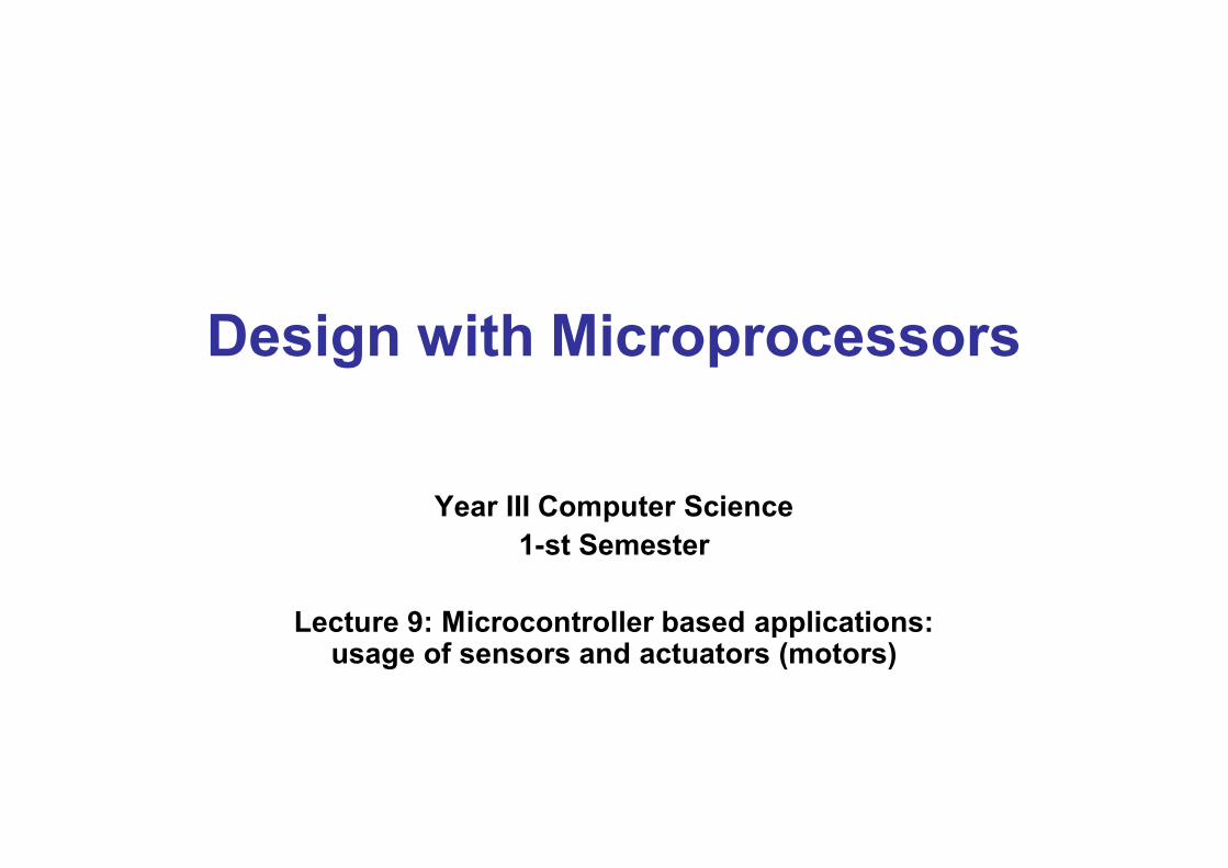
Design with Microprocessors Year III Computer Science 1-st Semester Lecture 9: Microcontroller based applications: usage of sensors and actuators (motors)
Transcript of Design with Microprocessors - utcluj.rousers.utcluj.ro/~tmarita/PMP/Lecture/C9.pdf · Design with...
Design with Microprocessors
Year III Computer Science
1-st Semester
Lecture 9: Microcontroller based applications: usage of sensors and actuators (motors)
DC motor control
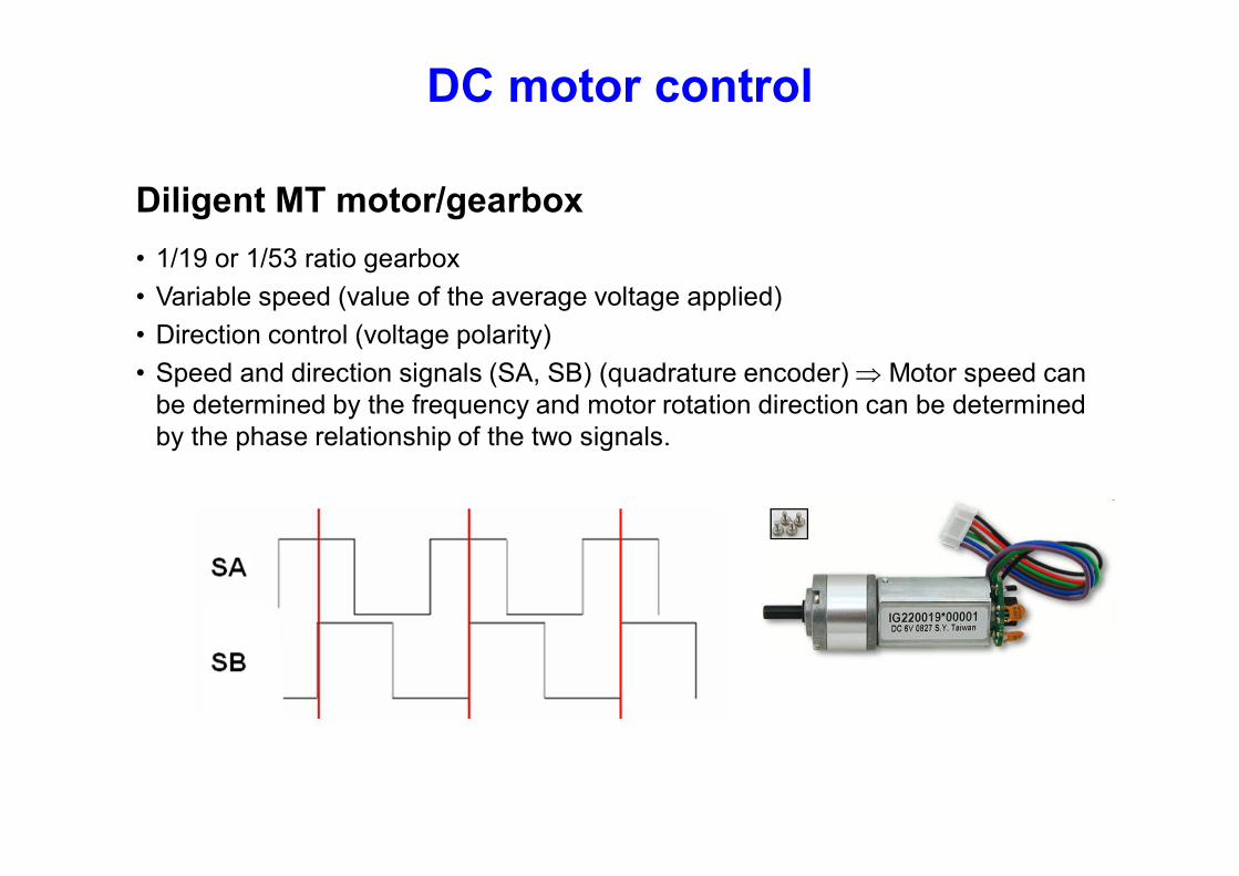
Diligent MT motor/gearbox
• 1/19 or 1/53 ratio gearbox
• Variable speed (value of the average voltage applied)
• Direction control (voltage polarity)
• Speed and direction signals (SA, SB) (quadrature encoder) Motor speed can be determined by the frequency and motor rotation direction can be determined by the phase relationship of the two signals.
DC motor control
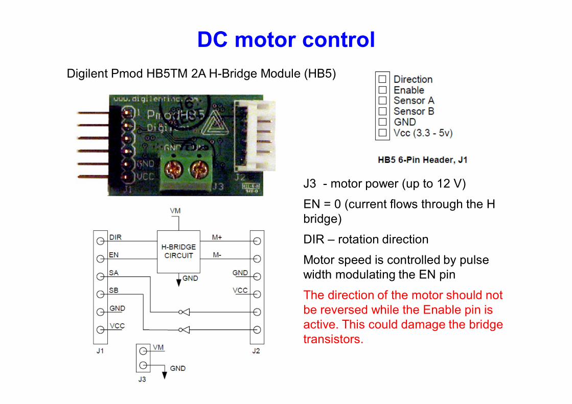
Digilent Pmod HB5TM 2A H-Bridge Module (HB5)
J3 - motor power (up to 12 V)
EN = 0 (current flows through the H bridge)
DIR – rotation direction
Motor speed is controlled by pulse width modulating the EN pin
The direction of the motor should not be reversed while the Enable pin is active. This could damage the bridge transistors.
DC motor control
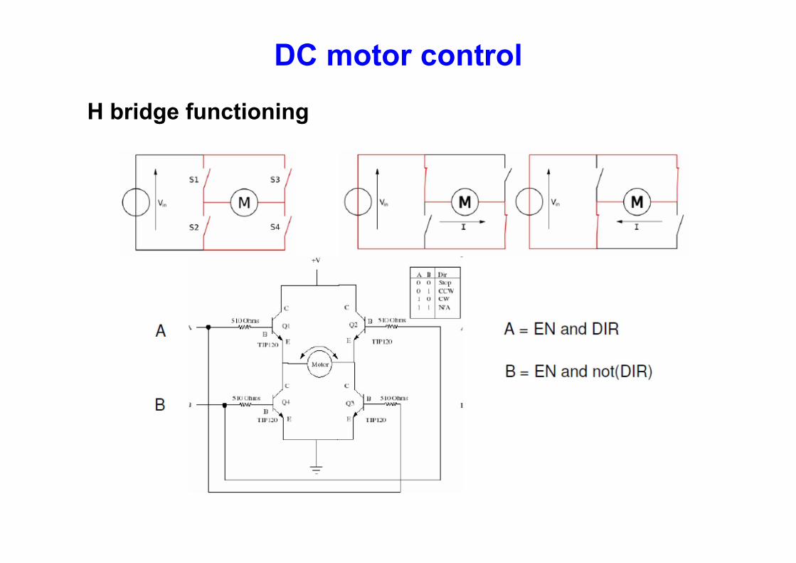
H bridge functioning
DC motor control
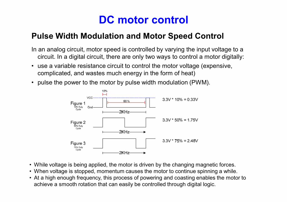
Pulse Width Modulation and Motor Speed Control
In an analog circuit, motor speed is controlled by varying the input voltage to a circuit. In a digital circuit, there are only two ways to control a motor digitally:
• use a variable resistance circuit to control the motor voltage (expensive, complicated, and wastes much energy in the form of heat)
• pulse the power to the motor by pulse width modulation (PWM).
• While voltage is being applied, the motor is driven by the changing magnetic forces. • When voltage is stopped, momentum causes the motor to continue spinning a while. • At a high enough frequency, this process of powering and coasting enables the motor to
achieve a smooth rotation that can easily be controlled through digital logic.
DC motor control
PWM driving issues
PWM has two important effects on DC motors:
• Inertial resistance is overcome more easily at startup because short bursts of maximum voltage achieve a greater degree of torque than the equivalent DC voltage.
• Higher level of heat generation inside the motor.
• If a pulsed motor is used for an extended time, heat dissipation systems may be needed to prevent damage to the motor. Because of these effects, PWM is best used in high-torque infrequent-use applications such as airplane flap servos and robotics.
• PWM circuits can also create radio frequency interference (RFI) that can be minimized by locating motors near the controller and by using short wires.
• Line noise created by continually powering up the motor may also need to be filtered to prevent interference with the rest of the circuits. Placing small ceramic capacitors directly across the motor terminals and between the motor terminals and the motor case can be used to filter RFI emissions from the motor.
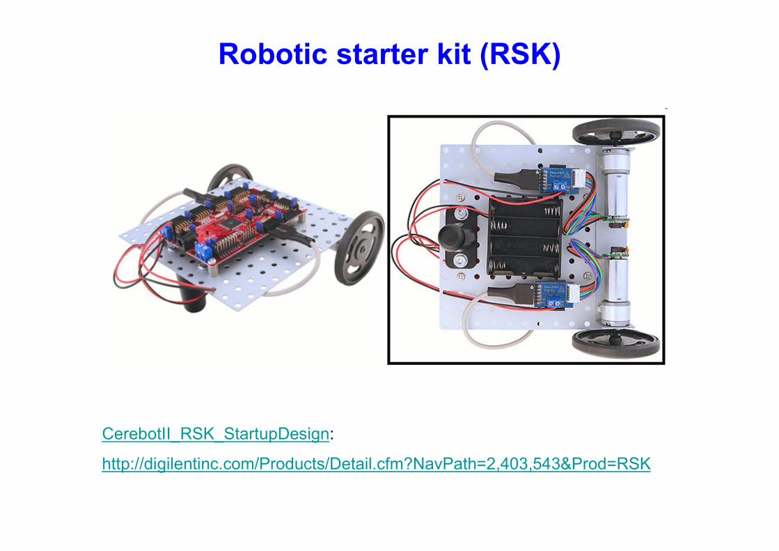
Robotic starter kit (RSK)
CerebotII_RSK_StartupDesign:
http://digilentinc.com/Products/Detail.cfm?NavPath=2,403,543&Prod=RSK
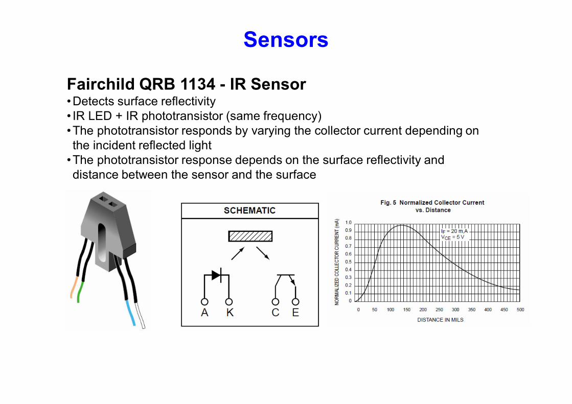
Sensors
Fairchild QRB 1134 - IR Sensor •Detects surface reflectivity • IR LED + IR phototransistor (same frequency) •The phototransistor responds by varying the collector current depending on the incident reflected light
•The phototransistor response depends on the surface reflectivity and distance between the sensor and the surface
Sensors
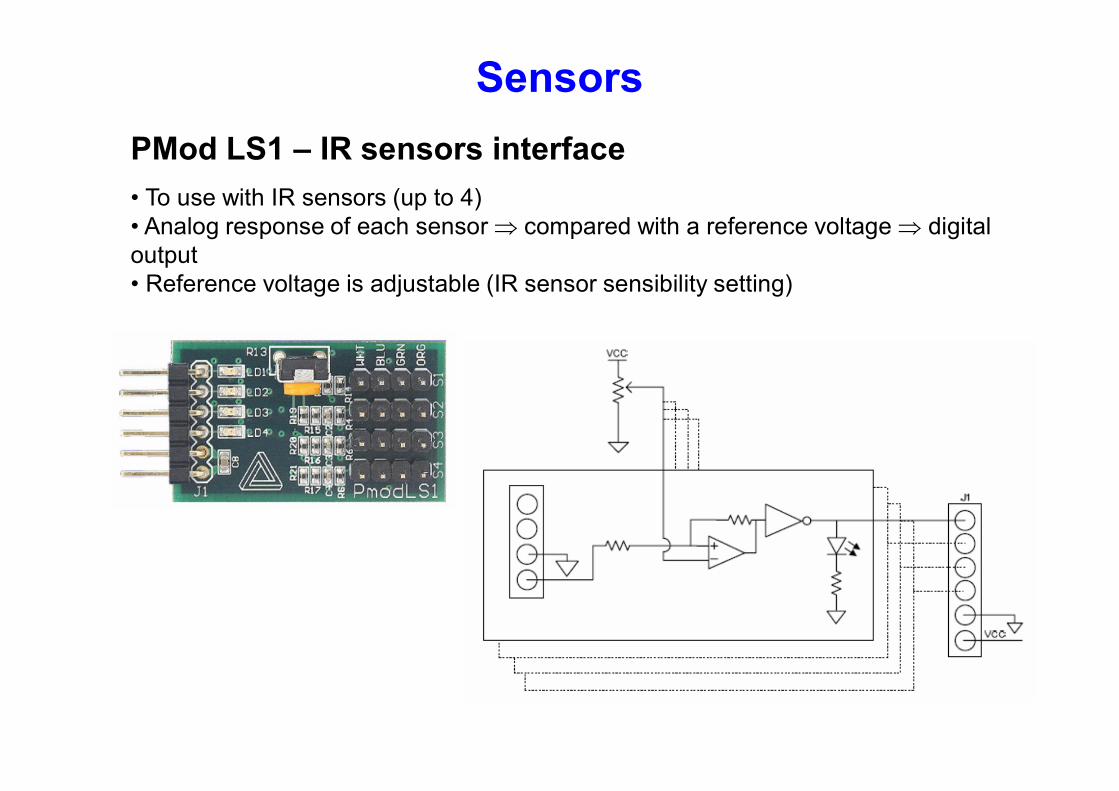
PMod LS1 – IR sensors interface
• To use with IR sensors (up to 4) • Analog response of each sensor compared with a reference voltage digital output • Reference voltage is adjustable (IR sensor sensibility setting)
Sonar range finder
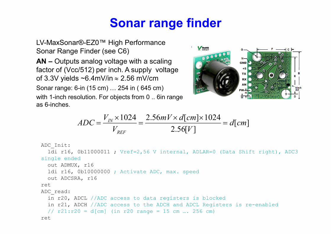
LV-MaxSonar®-EZ0™ High Performance Sonar Range Finder (see C6)
AN – Outputs analog voltage with a scaling factor of (Vcc/512) per inch. A supply voltage of 3.3V yields ~6.4mV/in 2.56 mV/cm
Sonar range: 6-in (15 cm) … 254 in ( 645 cm)
with 1-inch resolution. For objects from 0 .. 6in range as 6-inches.
][][56.2
1024][56.21024cmd
V
cmdmV
V
VADC
REF
IN
ADC_Init: ldi r16, 0b11000011 ; Vref=2,56 V internal, ADLAR=0 (Data Shift right), ADC3 single ended out ADMUX, r16 ldi r16, 0b10000000 ; Activate ADC, max. speed out ADCSRA, r16 ret ADC_read: in r20, ADCL //ADC access to data registers is blocked in r21, ADCH //ADC access to the ADCH and ADCL Registers is re-enabled // r21:r20 = d[cm] (in r20 range = 15 cm …. 256 cm) ret
Autonomous car
Cerebot II
Pmod Hb5
Pmod Hb5
Pmod LS1
Mt motor
Mt motor
IR Sensors
Pmod BTN
Lane (path)
US sensor
Heading direction
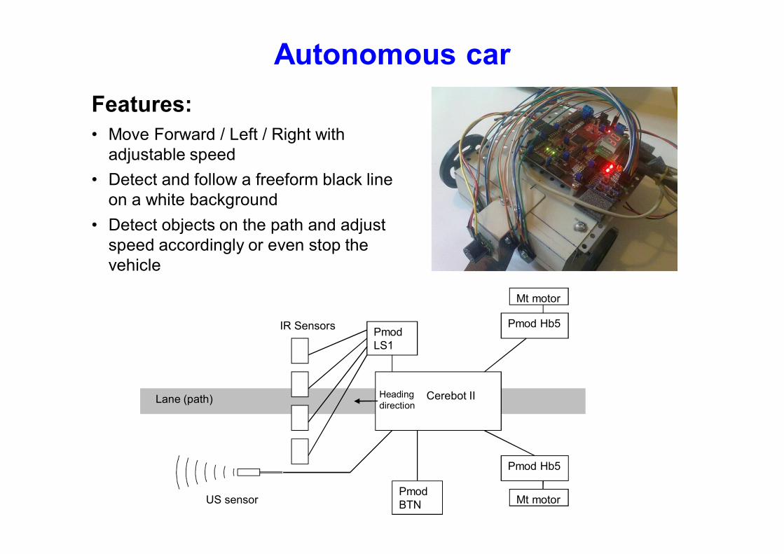
Features:
• Move Forward / Left / Right with adjustable speed
• Detect and follow a freeform black line on a white background
• Detect objects on the path and adjust speed accordingly or even stop the vehicle
Autonomous car
Autonomous car
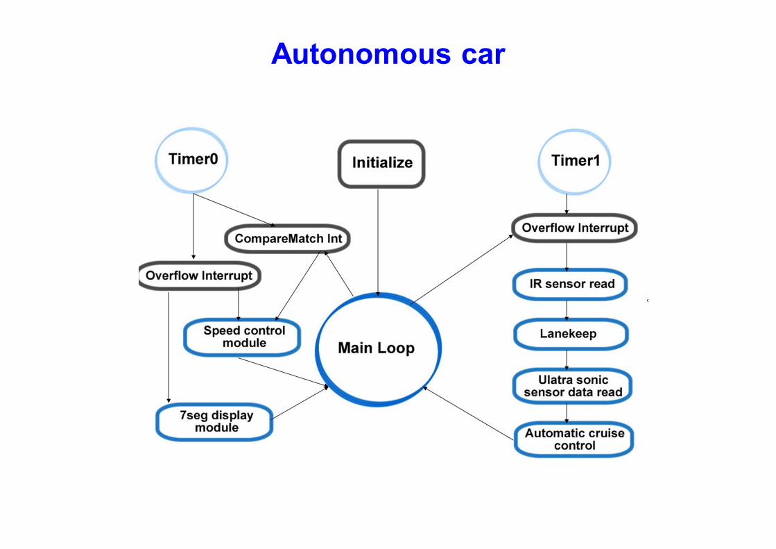
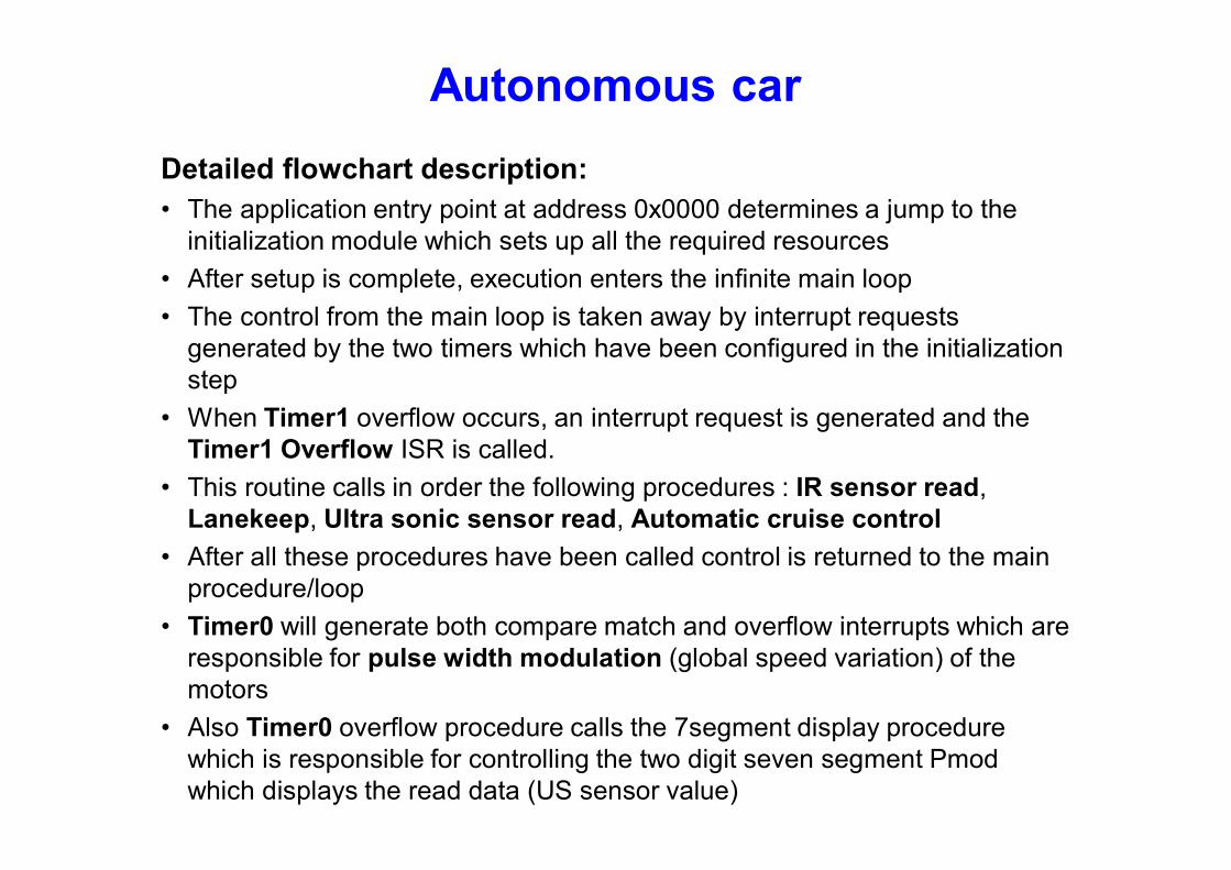
Detailed flowchart description:
• The application entry point at address 0x0000 determines a jump to the initialization module which sets up all the required resources
• After setup is complete, execution enters the infinite main loop
• The control from the main loop is taken away by interrupt requests generated by the two timers which have been configured in the initialization step
• When Timer1 overflow occurs, an interrupt request is generated and the Timer1 Overflow ISR is called.
• This routine calls in order the following procedures : IR sensor read, Lanekeep, Ultra sonic sensor read, Automatic cruise control
• After all these procedures have been called control is returned to the main procedure/loop
• Timer0 will generate both compare match and overflow interrupts which are responsible for pulse width modulation (global speed variation) of the motors
• Also Timer0 overflow procedure calls the 7segment display procedure which is responsible for controlling the two digit seven segment Pmod which displays the read data (US sensor value)
Autonomous car
http://www.youtube.com/watch?v=8797GgIC1WI
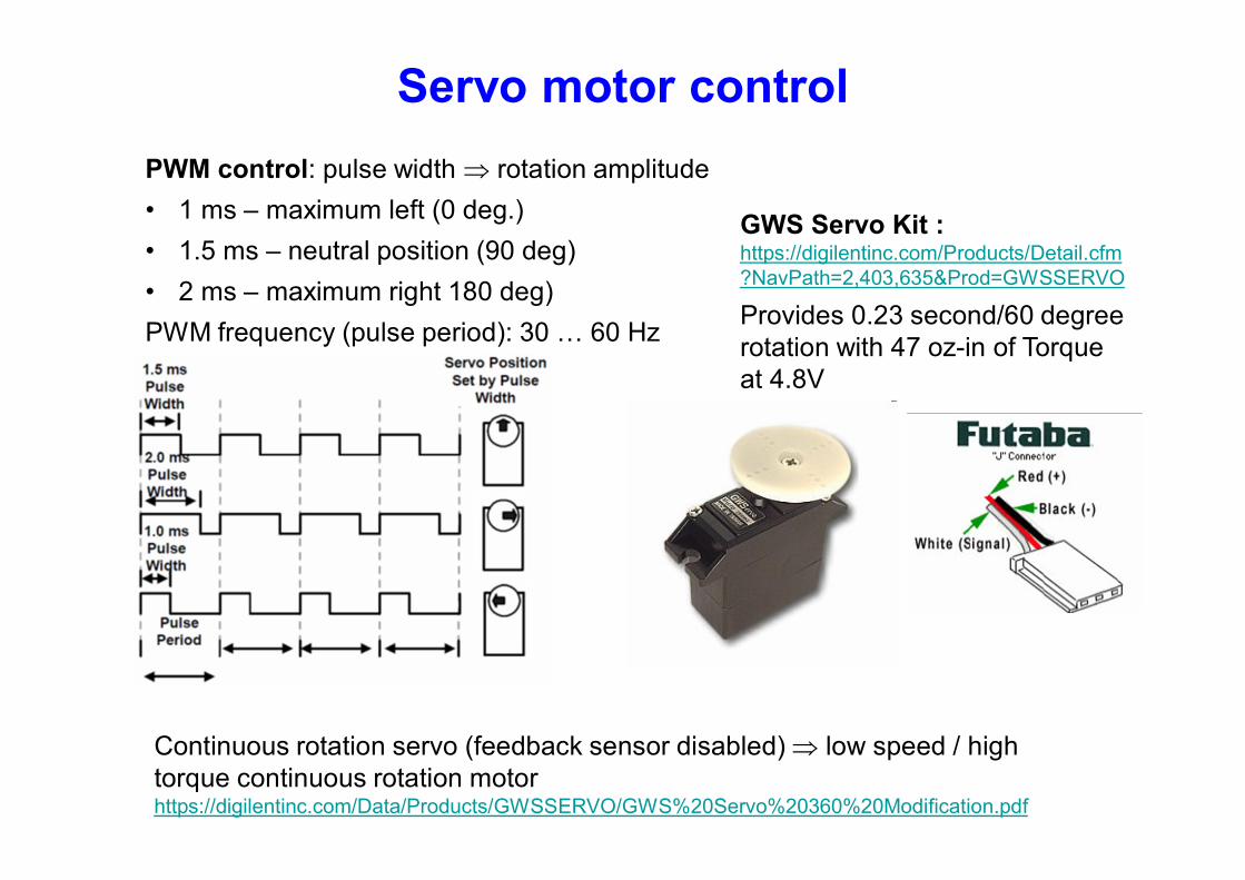
Servo motor control
PWM control: pulse width rotation amplitude
• 1 ms – maximum left (0 deg.)
• 1.5 ms – neutral position (90 deg)
• 2 ms – maximum right 180 deg)
PWM frequency (pulse period): 30 … 60 Hz
Continuous rotation servo (feedback sensor disabled) low speed / high torque continuous rotation motor https://digilentinc.com/Data/Products/GWSSERVO/GWS%20Servo%20360%20Modification.pdf
GWS Servo Kit : https://digilentinc.com/Products/Detail.cfm?NavPath=2,403,635&Prod=GWSSERVO
Provides 0.23 second/60 degree rotation with 47 oz-in of Torque at 4.8V
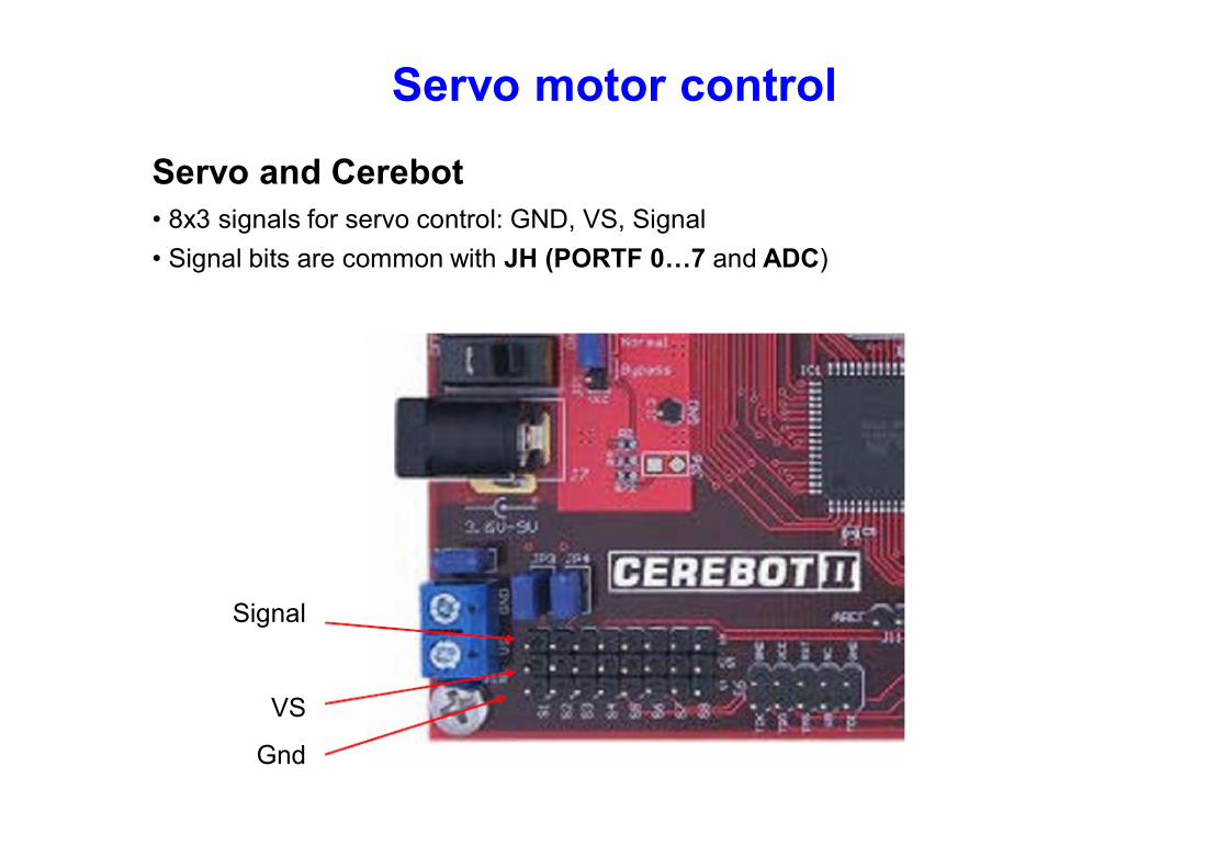
Servo motor control
Servo and Cerebot
• 8x3 signals for servo control: GND, VS, Signal
• Signal bits are common with JH (PORTF 0…7 and ADC)
Signal
VS
Gnd
Arduino Servo library
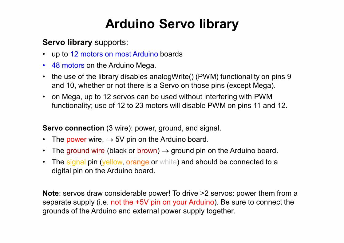
Servo library supports:
• up to 12 motors on most Arduino boards
• 48 motors on the Arduino Mega.
• the use of the library disables analogWrite() (PWM) functionality on pins 9 and 10, whether or not there is a Servo on those pins (except Mega).
• on Mega, up to 12 servos can be used without interfering with PWM functionality; use of 12 to 23 motors will disable PWM on pins 11 and 12.
Servo connection (3 wire): power, ground, and signal.
• The power wire, 5V pin on the Arduino board.
• The ground wire (black or brown) ground pin on the Arduino board.
• The signal pin (yellow, orange or white) and should be connected to a digital pin on the Arduino board.
Note: servos draw considerable power! To drive >2 servos: power them from a separate supply (i.e. not the +5V pin on your Arduino). Be sure to connect the grounds of the Arduino and external power supply together.
Arduino Servo library
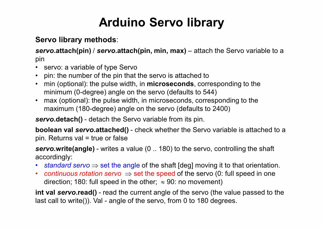
Servo library methods:
servo.attach(pin) / servo.attach(pin, min, max) – attach the Servo variable to a pin • servo: a variable of type Servo • pin: the number of the pin that the servo is attached to • min (optional): the pulse width, in microseconds, corresponding to the
minimum (0-degree) angle on the servo (defaults to 544) • max (optional): the pulse width, in microseconds, corresponding to the
maximum (180-degree) angle on the servo (defaults to 2400)
servo.detach() - detach the Servo variable from its pin.
boolean val servo.attached() - check whether the Servo variable is attached to a pin. Returns val = true or false
servo.write(angle) - writes a value (0 .. 180) to the servo, controlling the shaft accordingly: • standard servo set the angle of the shaft [deg] moving it to that orientation. • continuous rotation servo set the speed of the servo (0: full speed in one
direction; 180: full speed in the other; 90: no movement)
int val servo.read() - read the current angle of the servo (the value passed to the last call to write()). Val - angle of the servo, from 0 to 180 degrees.
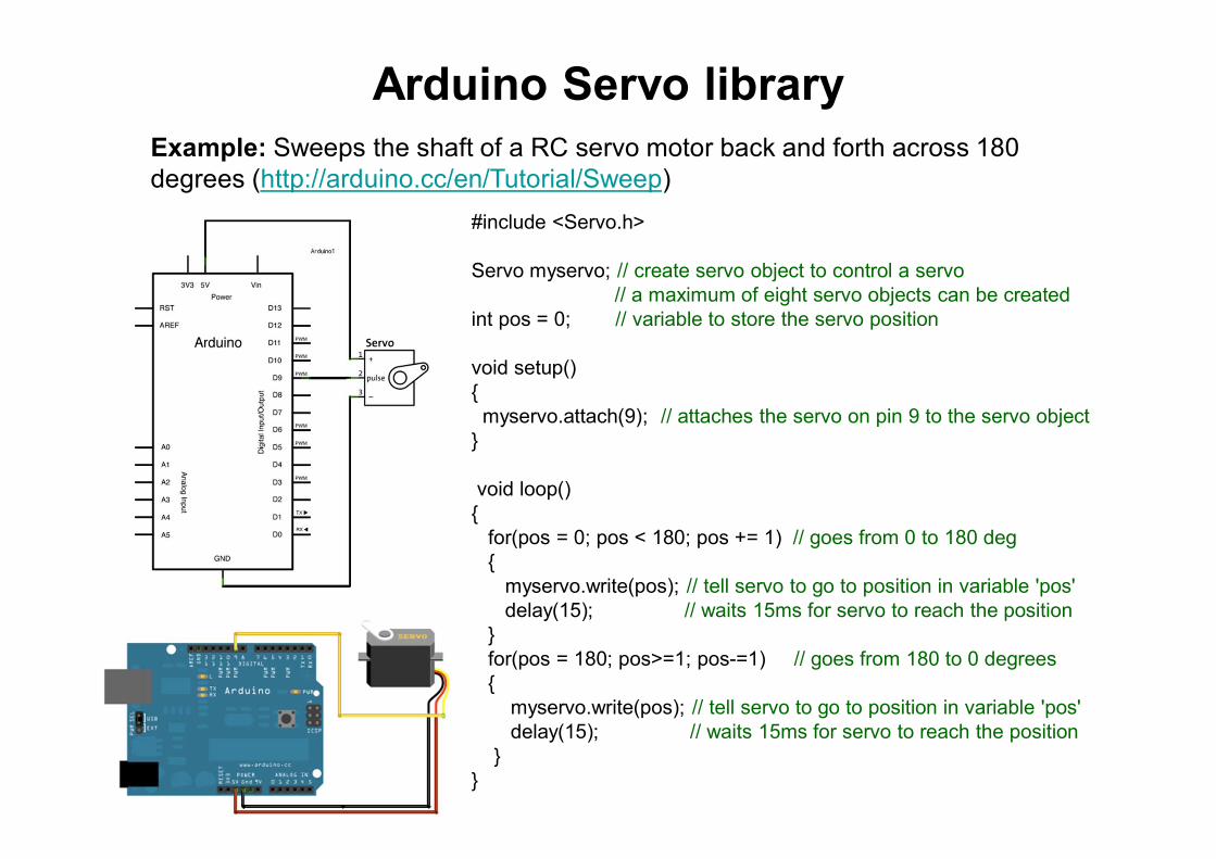
Arduino Servo library Example: Sweeps the shaft of a RC servo motor back and forth across 180 degrees (http://arduino.cc/en/Tutorial/Sweep)
#include <Servo.h> Servo myservo; // create servo object to control a servo // a maximum of eight servo objects can be created int pos = 0; // variable to store the servo position void setup() { myservo.attach(9); // attaches the servo on pin 9 to the servo object } void loop() { for(pos = 0; pos < 180; pos += 1) // goes from 0 to 180 deg { myservo.write(pos); // tell servo to go to position in variable 'pos' delay(15); // waits 15ms for servo to reach the position } for(pos = 180; pos>=1; pos-=1) // goes from 180 to 0 degrees { myservo.write(pos); // tell servo to go to position in variable 'pos' delay(15); // waits 15ms for servo to reach the position } }
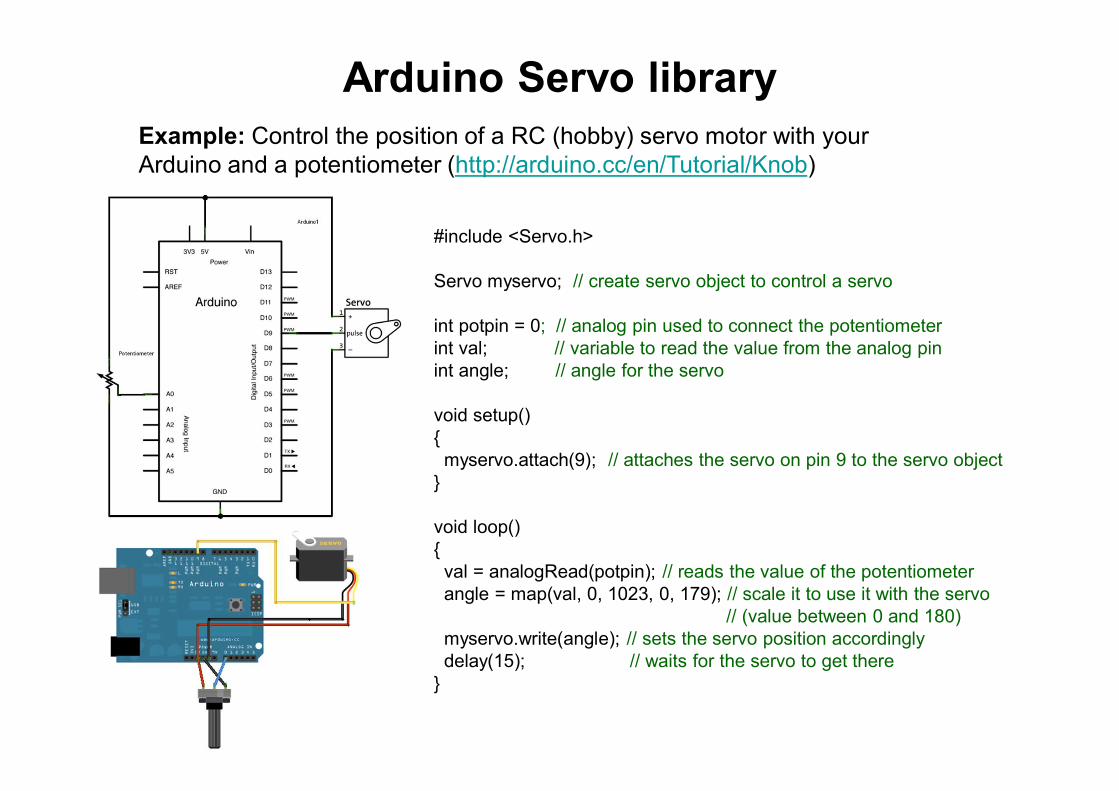
Arduino Servo library Example: Control the position of a RC (hobby) servo motor with your Arduino and a potentiometer (http://arduino.cc/en/Tutorial/Knob)
#include <Servo.h> Servo myservo; // create servo object to control a servo int potpin = 0; // analog pin used to connect the potentiometer int val; // variable to read the value from the analog pin int angle; // angle for the servo void setup() { myservo.attach(9); // attaches the servo on pin 9 to the servo object } void loop() { val = analogRead(potpin); // reads the value of the potentiometer angle = map(val, 0, 1023, 0, 179); // scale it to use it with the servo // (value between 0 and 180) myservo.write(angle); // sets the servo position accordingly delay(15); // waits for the servo to get there }
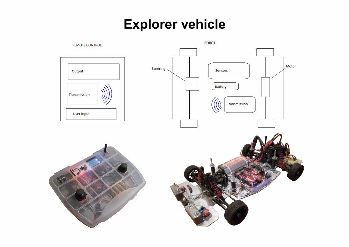
Explorer vehicle
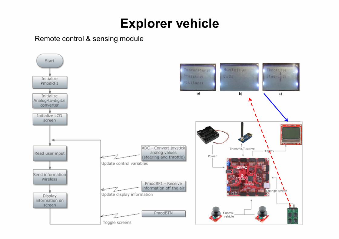
Explorer vehicle Remote control & sensing module
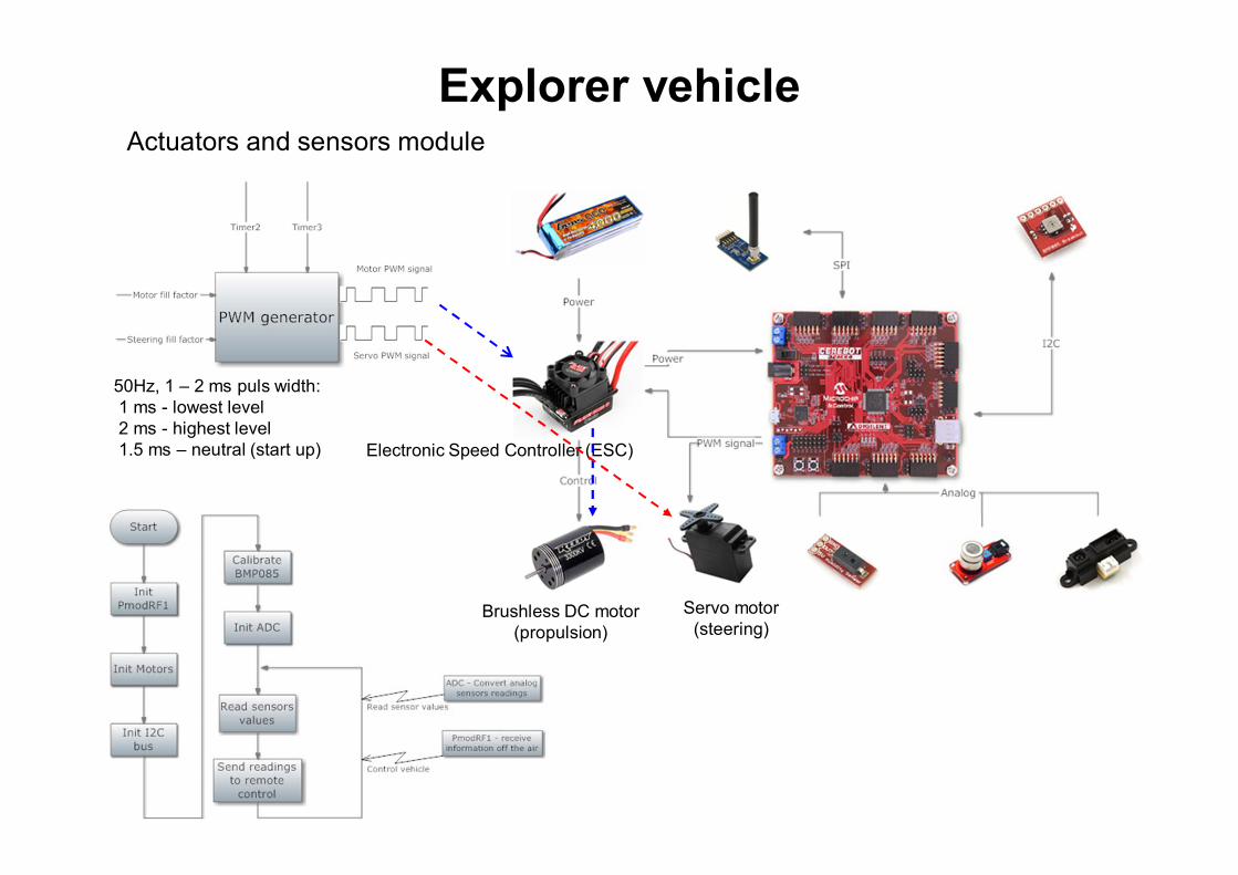
Explorer vehicle Actuators and sensors module
Electronic Speed Controller (ESC)
Brushless DC motor (propulsion)
Servo motor (steering)
50Hz, 1 – 2 ms puls width: 1 ms - lowest level 2 ms - highest level 1.5 ms – neutral (start up)
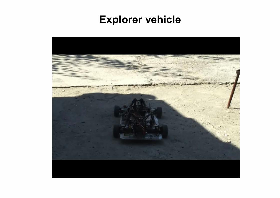
Explorer vehicle
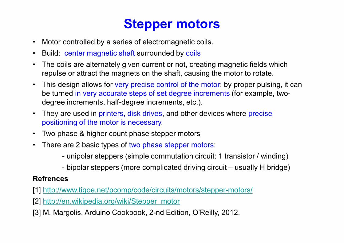
Stepper motors • Motor controlled by a series of electromagnetic coils.
• Build: center magnetic shaft surrounded by coils
• The coils are alternately given current or not, creating magnetic fields which repulse or attract the magnets on the shaft, causing the motor to rotate.
• This design allows for very precise control of the motor: by proper pulsing, it can be turned in very accurate steps of set degree increments (for example, two-degree increments, half-degree increments, etc.).
• They are used in printers, disk drives, and other devices where precise positioning of the motor is necessary.
• Two phase & higher count phase stepper motors
• There are 2 basic types of two phase stepper motors:
- unipolar steppers (simple commutation circuit: 1 transistor / winding)
- bipolar steppers (more complicated driving circuit – usually H bridge)
Refrences
[1] http://www.tigoe.net/pcomp/code/circuits/motors/stepper-motors/
[2] http://en.wikipedia.org/wiki/Stepper_motor
[3] M. Margolis, Arduino Cookbook, 2-nd Edition, O’Reilly, 2012.
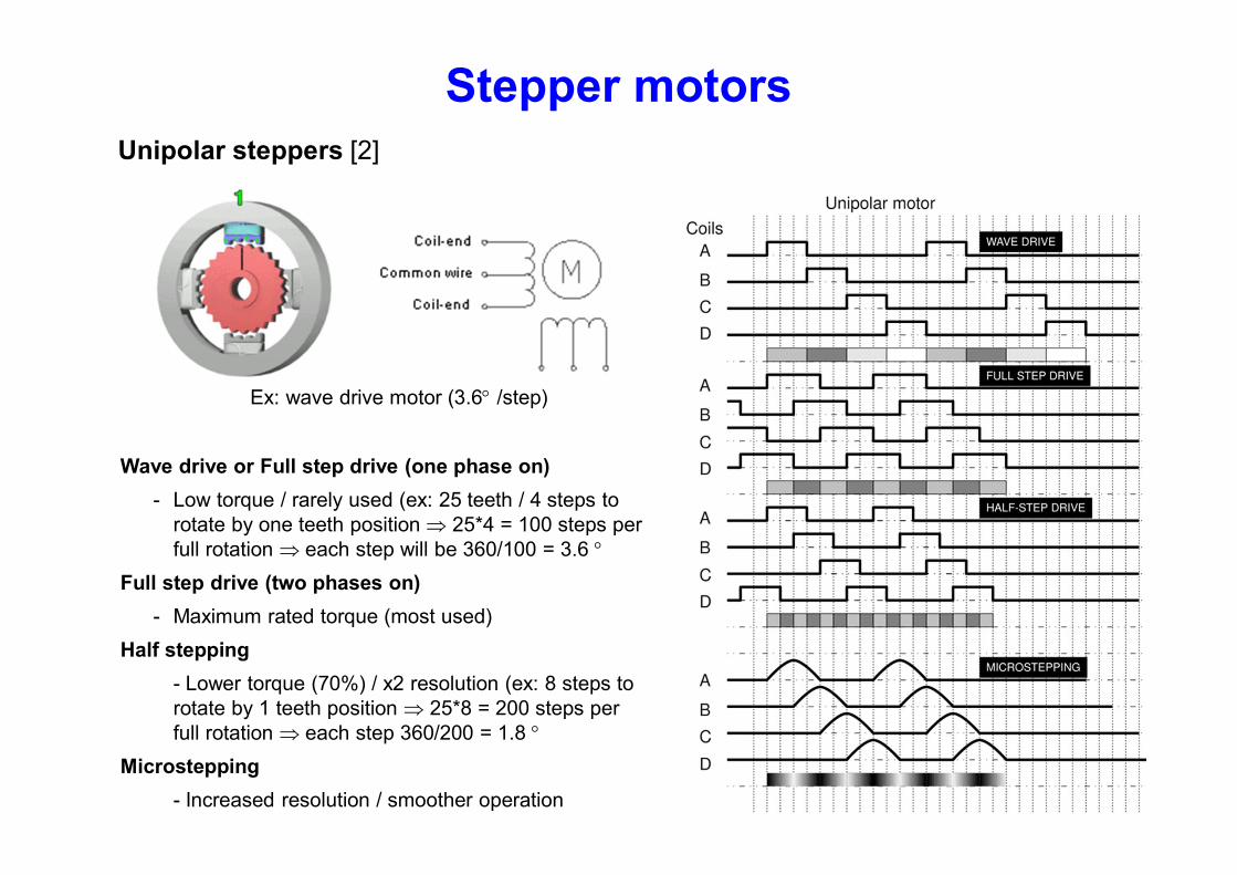
Stepper motors Unipolar steppers [2]
Wave drive or Full step drive (one phase on)
- Low torque / rarely used (ex: 25 teeth / 4 steps to rotate by one teeth position 25*4 = 100 steps per full rotation each step will be 360/100 = 3.6
Full step drive (two phases on)
- Maximum rated torque (most used)
Half stepping
- Lower torque (70%) / x2 resolution (ex: 8 steps to rotate by 1 teeth position 25*8 = 200 steps per full rotation each step 360/200 = 1.8
Microstepping
- Increased resolution / smoother operation
Ex: wave drive motor (3.6 /step)
Stepper motors
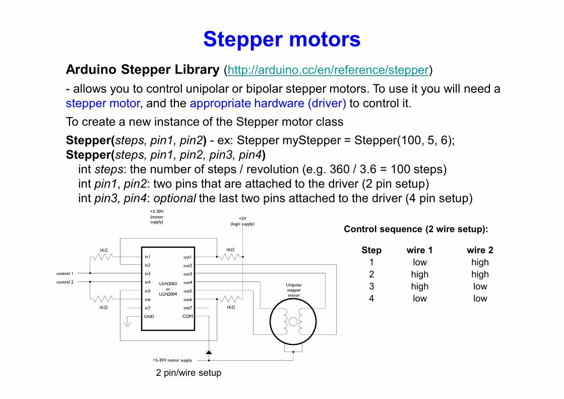
Arduino Stepper Library (http://arduino.cc/en/reference/stepper)
- allows you to control unipolar or bipolar stepper motors. To use it you will need a stepper motor, and the appropriate hardware (driver) to control it.
To create a new instance of the Stepper motor class
Stepper(steps, pin1, pin2) - ex: Stepper myStepper = Stepper(100, 5, 6); Stepper(steps, pin1, pin2, pin3, pin4)
int steps: the number of steps / revolution (e.g. 360 / 3.6 = 100 steps) int pin1, pin2: two pins that are attached to the driver (2 pin setup) int pin3, pin4: optional the last two pins attached to the driver (4 pin setup)
2 pin/wire setup
Step wire 1 wire 2
1 low high
2 high high
3 high low
4 low low
Control sequence (2 wire setup):
Stepper motors
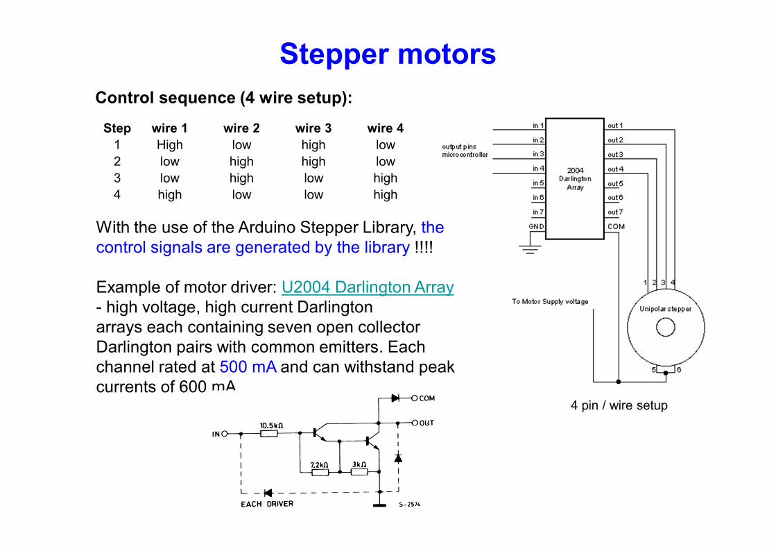
4 pin / wire setup
Control sequence (4 wire setup):
Step wire 1 wire 2 wire 3 wire 4
1 High low high low
2 low high high low
3 low high low high
4 high low low high
With the use of the Arduino Stepper Library, the control signals are generated by the library !!!! Example of motor driver: U2004 Darlington Array - high voltage, high current Darlington arrays each containing seven open collector Darlington pairs with common emitters. Each channel rated at 500 mA and can withstand peak currents of 600 mA.
Stepper motors
Arduino Stepper Library (http://arduino.cc/en/reference/stepper)
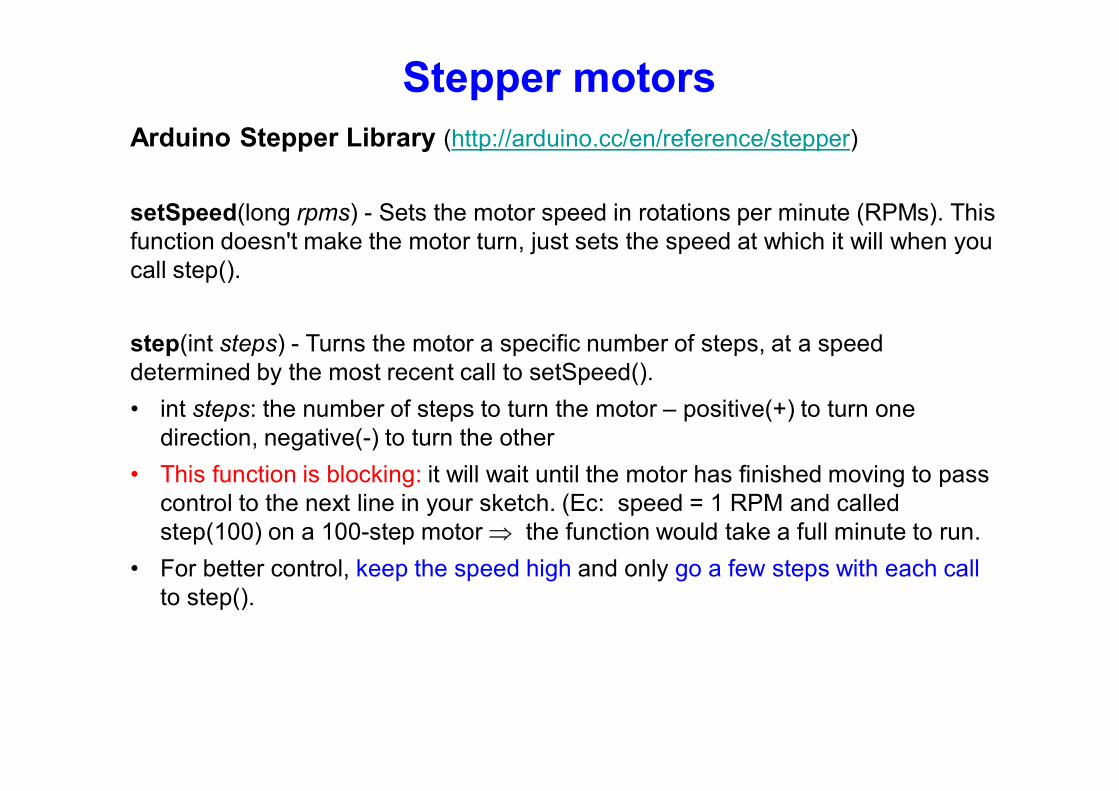
setSpeed(long rpms) - Sets the motor speed in rotations per minute (RPMs). This function doesn't make the motor turn, just sets the speed at which it will when you call step().
step(int steps) - Turns the motor a specific number of steps, at a speed determined by the most recent call to setSpeed().
• int steps: the number of steps to turn the motor – positive(+) to turn one direction, negative(-) to turn the other
• This function is blocking: it will wait until the motor has finished moving to pass control to the next line in your sketch. (Ec: speed = 1 RPM and called step(100) on a 100-step motor the function would take a full minute to run.
• For better control, keep the speed high and only go a few steps with each call to step().
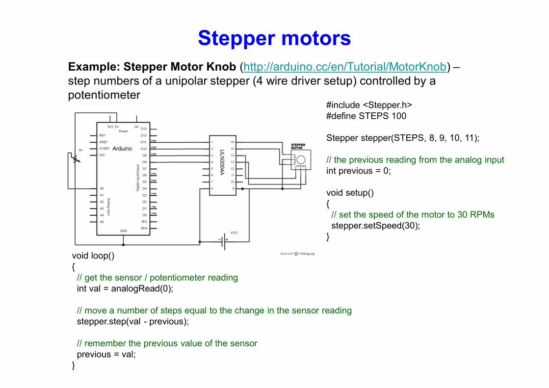
Stepper motors Example: Stepper Motor Knob (http://arduino.cc/en/Tutorial/MotorKnob) – step numbers of a unipolar stepper (4 wire driver setup) controlled by a potentiometer
#include <Stepper.h> #define STEPS 100 Stepper stepper(STEPS, 8, 9, 10, 11); // the previous reading from the analog input int previous = 0; void setup() { // set the speed of the motor to 30 RPMs stepper.setSpeed(30); }
void loop() { // get the sensor / potentiometer reading int val = analogRead(0); // move a number of steps equal to the change in the sensor reading stepper.step(val - previous); // remember the previous value of the sensor previous = val; }
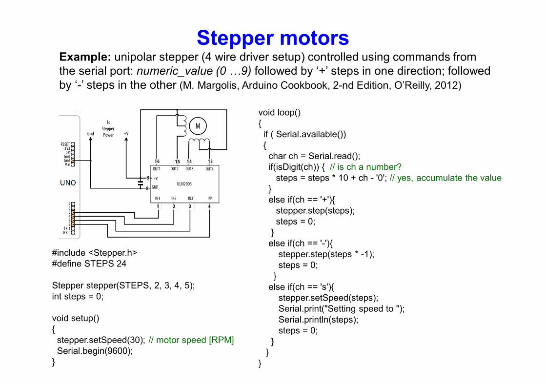
Stepper motors Example: unipolar stepper (4 wire driver setup) controlled using commands from the serial port: numeric_value (0 …9) followed by ‘+’ steps in one direction; followed by ‘-’ steps in the other (M. Margolis, Arduino Cookbook, 2-nd Edition, O’Reilly, 2012)
#include <Stepper.h> #define STEPS 24 Stepper stepper(STEPS, 2, 3, 4, 5); int steps = 0; void setup() { stepper.setSpeed(30); // motor speed [RPM] Serial.begin(9600); }
void loop() { if ( Serial.available()) { char ch = Serial.read(); if(isDigit(ch)) { // is ch a number? steps = steps * 10 + ch - '0'; // yes, accumulate the value } else if(ch == '+'){ stepper.step(steps); steps = 0; } else if(ch == '-'){ stepper.step(steps * -1); steps = 0; } else if(ch == 's'){ stepper.setSpeed(steps); Serial.print("Setting speed to "); Serial.println(steps); steps = 0; } } }


![Design (Systems) with Microprocessorsusers.utcluj.ro/~tmarita/PMP/Lecture/C12.pdf · Design with Microprocessors ... address translation speed.[1] ... Function –functionality, nature](https://static.fdocuments.in/doc/165x107/5b82548c7f8b9ae87c8e4aa9/design-systems-with-tmaritapmplecturec12pdf-design-with-microprocessors.jpg)