Lab-size aerosol lidar chamber: on the road to...
24
Defence Research and Development Canada Recherche et développement pour la défense Canada Canada Lab-size aerosol lidar chamber: on the road to optimization Sylvie Buteau Supporting team: D. Nadeau, J.-R. Simard, C. Laflamme, P. Lahaie, G. Roy, P. Mathieu SBWG July 2010 (Dstl, UK)
Transcript of Lab-size aerosol lidar chamber: on the road to...

Defence Research andDevelopment Canada
Recherche et développementpour la défense Canada Canada
Lab-size aerosol lidar chamber: on the road to optimization
Sylvie ButeauSupporting team: D. Nadeau, J.-R. Simard, C. Laflamme, P. Lahaie, G. Roy,
P. Mathieu
SBWG July 2010 (Dstl, UK)

Defence R&D Canada • R & D pour la défense Canada
Presentation focus
Artefact source findings and improvements
Original chamber design
System limitations/artefacts

Defence R&D Canada • R & D pour la défense Canada
Lab-size chamber: original design
Short-range bi-axial LIDAR system (355nm) Closed system: control over the environment Dissemination of liquids and dissolved powders
Particles counter
TelescopeBeamBeam expanderexpanderMixingMixing
chamberchamber
Main ChamberSpectrometer
ICCD

Defence R&D Canada • R & D pour la défense Canada
Artifact 1: Laser power drop

Defence R&D Canada • R & D pour la défense Canada
Artifact 1: power drop mitigation
Temperature Ctrl
Heating pads
Thermocouple
Thermal-compensation process + new chiller

Defence R&D Canada • R & D pour la défense Canada
Artifact 2: wet dissemination
Low signal to noise ratio versus concentration
Collison Nebuliser
Defence R&D Canada • R & D pour la défense Canada
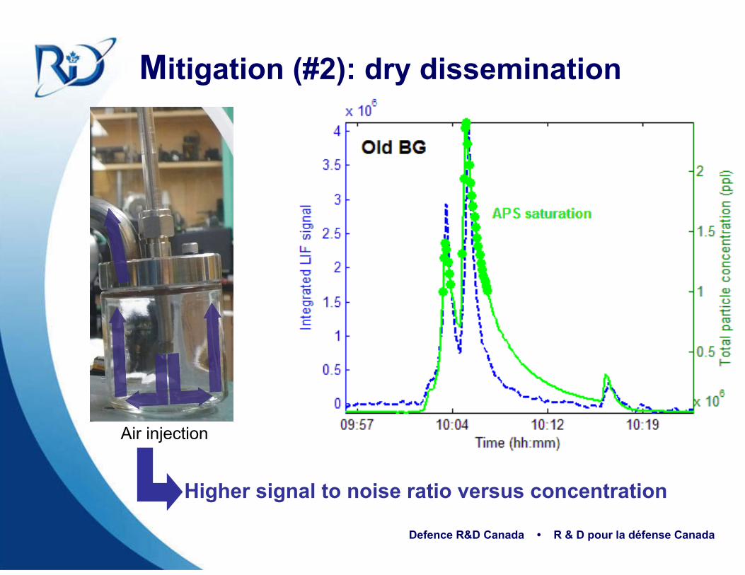
Mitigation (#2): dry dissemination
Higher signal to noise ratio versus concentration
Air injection

Defence R&D Canada • R & D pour la défense Canada
Particle size distribution: wet versus dry BG
WetDry
Only few aggregatesMany small particles (32%)
More aggregates Less small particles (3%)

Defence R&D Canada • R & D pour la défense Canada
Source of the higher LIF signal (wet/dry)?
Particle size distribution
Aerosol quantum yield

Defence R&D Canada • R & D pour la défense Canada
LIDAR equation for a fluorescent target
λλλ
λλ
πσ ,0
0
4A a
aaaaaa PNNE Ψ⋅⋅=⋅∝
0000 ,ra
,ac
,aeoc2
0 0pu NAEn λλλλλλλ σξ a
rroe
r rttttr
Δ⋅=raE,, 0λλ
Energydelivered Geometry
OpticsAtmosphere
Columnthickness
Aerosolproperties
Collected Energy
approximations
⋅⋅=i
iiAa dnrN 2π
Plot LIF metric vs NA
0λaslope Ψ∝
Projected area weighted concentration

Defence R&D Canada • R & D pour la défense Canada
Higher LIF signal for dry versus wet BG
Wet Dry
Higher quantum yield for dry BG versus wet BG

Defence R&D Canada • R & D pour la défense Canada
Artifact 3: Limited control over dissemination
Difficult to replicate a given dissemination
scheme
Low control over the concentration within
the chamber
Old BG dry
Defence R&D Canada • R & D pour la défense Canada
Mitigation (#3): Design of new disseminator
Small Scale Powder Disperser (SSPD)
In-house design (D. Nadeau); Dissemination of dry sample; Fully automated dissemination; Controlled by adapted software; Sealed enclosure.
Disseminated quantity adjustment:
Plate groove; Plate speed; Injected air pressure
Defence R&D Canada • R & D pour la défense Canada
Mitigation (#3): SSPD disseminator
Better control over the dissemination scheme

Defence R&D Canada • R & D pour la défense Canada
SSPD disseminator: particle size distribution
SSPD is effective to minimize particle aggregates
Dry Old BG

Defence R&D Canada • R & D pour la défense Canada
Artifact 4: LIF-APS correlation non-linearityNew BG dry (BHI media)
No impact on the signature extraction
Limitation on the cross-section
evaluation

Defence R&D Canada • R & D pour la défense Canada
Artifact 4: Possible sources
APS saturation effect
Bleaching effects
APS sampling effectiveness
Dissemination in-homogeneity
Particle size distribution evolution

Defence R&D Canada • R & D pour la défense Canada
Artifact 4 : APS saturation?
APS saturation will produce non-linearity (at a higher level than the default setting of 1Mppl)
Old BG dry (SSPD)

Defence R&D Canada • R & D pour la défense Canada
Artifact 4 : Bleaching effects?
Difficult to isolate the bleaching effect contribution with the actual set-up following variable testing conditions

Defence R&D Canada • R & D pour la défense Canada
Artifact 4 : APS sampling effectiveness?
Particle velocity and their Stokes number (Stk) may vary significantly due to injection of air during dissemination
In –chamber air flow
APS sampling
(90°)

Defence R&D Canada • R & D pour la défense Canada
Mitigation (#4): LIF- APS non-linearity
Possible bleaching effect No recirculation of the material (open loop chamber) Adjust flow velocity for minimum bleaching effects More testing is needed to assess the bleaching properties
APS sampling Relocate the APS sampling input Adjust in-chamber flow velocity with the APS sampling flow This will be implement only in the new chamber design
APS saturation Ensure the concentration levels are below 1 Mppl

Defence R&D Canada • R & D pour la défense Canada
Other system design observations
In coming flow
Air injection
(SSPD)
Injection orientation interfere with the circling
particle flow
Mixing chamber geometry not optimum for material aerosolization

Defence R&D Canada • R & D pour la défense Canada
Conclusion
System artefacts and limitations
Acquiring data and gaining expertise with the
original chamber
Investigations
Optimised design for the next
chamberFluorescence cross-section evaluation

Defence R&D Canada • R & D pour la défense Canada