L38 Owner's Manual Rev 0(1)svastralwind.com/uploads/3/4/0/2/34024178/l38_owners_manual.pdf ·...
63
Transcript of L38 Owner's Manual Rev 0(1)svastralwind.com/uploads/3/4/0/2/34024178/l38_owners_manual.pdf ·...


OWNER’S MANUAL REVISION 0 (11/02/03)
THREE CABIN VERSION
ZA RAC 38057 D303
ROBERTSON AND CAINE (PTY) LTD CAPE TOWN SOUTH AFRICA

OWNER’S MANUAL
L38 OM 110v Rev0 (11/02/03) Page 1
INDEX 1. Introduction 2. Issue sheet 3. Warranties 4. Copy of Builder’s Plate 5. List of ISO Standards Applicable 6. Certificate of Conformity 7. Warning Symbols on Board 8. Prevention of Capsize 9. Load Calculations Specifications. 10. Ecological / Operational Aspects 11. Fire Fighting 12. Life raft Stowage 13. Gas System Operation 14. Bilge Pump Operation 15. Toilet Operation 16. Fresh Water System Operation. 17. Steering 18. Engine room Systems 19. Electrical System DC Battery operation
Windlass operation. 20. Electrical System AC 21. Fridge / Freezer Operation 22. Air-Conditioning 23. Lay up and Winterization. 24. Hull Transport. 25. Cleaning and Maintenance 26. Index of manuals 27. Index of drawings

OWNER’S MANUAL
L38 OM 110v Rev0 (11/02/03) Page 2
1. INTRODUCTION READ THIS OWNER’S MANUAL CAREFULLY BEFORE YOU GO SAILING AND REFER TO IT FREQUENTLY DURING YOUR OWNERSHIP. MAKE SURE THAT THIS MANUAL IS TRANSFERRED TO SUBSEQUENT OWNERS. While all the information it contains is important, items of special importance to you are shown in CAPITALS. If your experience in sailing, or yacht ownership is limited you are strongly advised to take instruction from a professional, registered sailing institution. This owner’s manual is written in conformance with the European Recreation Craft Directive 94/25/EC and the notified body is the European Certification Bureau Netherlands B.V. Address: Juliana weg 224A 1131 NW Volendam
Telephone: + 31 (0) 299 323 123 or 320 477 Fax: + 31 (0) 299 323 023 e-mail: [email protected] Internet: www.ecb.nl

OWNER’S MANUAL
L38 OM 110v Rev0 (11/02/03) Page 3
2. ISSUE SHEET HULL IDENTIFICATION NUMBER: ZA RAC 38057 D303 THIS DOCUMENT IS ISSUED BY ROBERTSON AND CAINE (PTY) LTD OF CAPE TOWN, SOUTH AFRICA. DATE: 24 March 2003 QUALITY ASSURANCE MANAGER RECEIVED: DATE FIRST OWNER SUBSEQUENT ISSUES ON CHANGE OF OWNERSHIP SUPPLIED BY RECEIVED BY 2 SELLER BUYER DATE DATE 3 SELLER BUYER DATE DATE

OWNER’S MANUAL
L38 OM 110v Rev0 (11/02/03) Page 4
3. WARRANTIES The warranty that applies to the yacht, from the yacht builders and the suppliers of the equipment is described in the Memorandum of Agreement between the Builder and the Purchaser.

OWNER’S MANUAL
L38 OM 110v Rev0 (11/02/03) Page 5
4. COPY OF BUILDER’S PLATE

OWNER’S MANUAL
L38 OM 110v Rev0 (11/02/03) Page 6
5. List of ISO Standards Applicable ISO 8099-1/2/3 Small Craft - Waste water retention and treatment systems Parts 1,2,3
EN/ISO 8665 Small craft - Marine propulsion engines and systems – Power measurements and declarations
ISO 8666 Small craft - Principal data
EN 28846 Small craft - Electrical devices -Protection against ignition of surrounding flammable gases
EN 28848 Small craft - Remote steering systems
EN 28849 Small craft - Electrically operated bilge-pumps
ISO 9093 – ½ Small craft - Seacocks and through-hull fittings
EN/ISO 9097 Small craft - Electric fans
EN/ISO 10087 Hull identification - Coding system
ISO 10088 Small craft - Permanently installed fuel systems and Fixed fuel tanks
ISO 10133 Small craft - Electrical systems - Extra-low-voltage D.C. Installations
ISO.10239 Small craft - Liquefied petroleum gas (LPG) systems
EN/ISO 10240 Owner’s manual
ISO 11812 Small craft - Cockpit and cockpit drainage
ISO 12215-1 Small craft - Hull construction - Scantlings - Part 1: Materials thermosetting resins, glass fibre reinforcement, reference laminate
ISO 12215-4 Small craft - Hull construction - Scantlings - Part 4: Workshop and construction
ISO 12216 Small craft - Windows, portlights, hatches, deadlights and doors - Strength and tightness requirements
ISO 12217-2 Small craft - Stability and buoyancy - Methods of assessment and categorisation - Part 2: Sailing boats
ISO 13297 Small craft - Electrical systems. Alternating current installations
ISO 14945 Small craft – Builder’s plate
ISO 14946 Small craft - Maximum load capacity
ISO 15083 Small craft - Bilge pumping systems
ISO 15084 Small craft - Anchoring, mooring and towing - Strong points
ISO 15085 Guard-rails, lifelines and handrails

OWNER’S MANUAL
L38 OM 110v Rev0 (11/02/03) Page 7
6. Certificate of Conformity It is hereby certified that, to the best of our capacity, and as determined by our Quality Control System, this yacht is built in accordance with the prescribed Technical Construction details and in accordance with the ISO Standards listed in Section 5 of this manual. Rob Brennan Quality Assurance Manager For Robertson and Caine (Pty) Ltd Date: 24 March 2003
OWNER’S MANUAL
L38 OM 110v Rev0 (11/02/03) Page 8
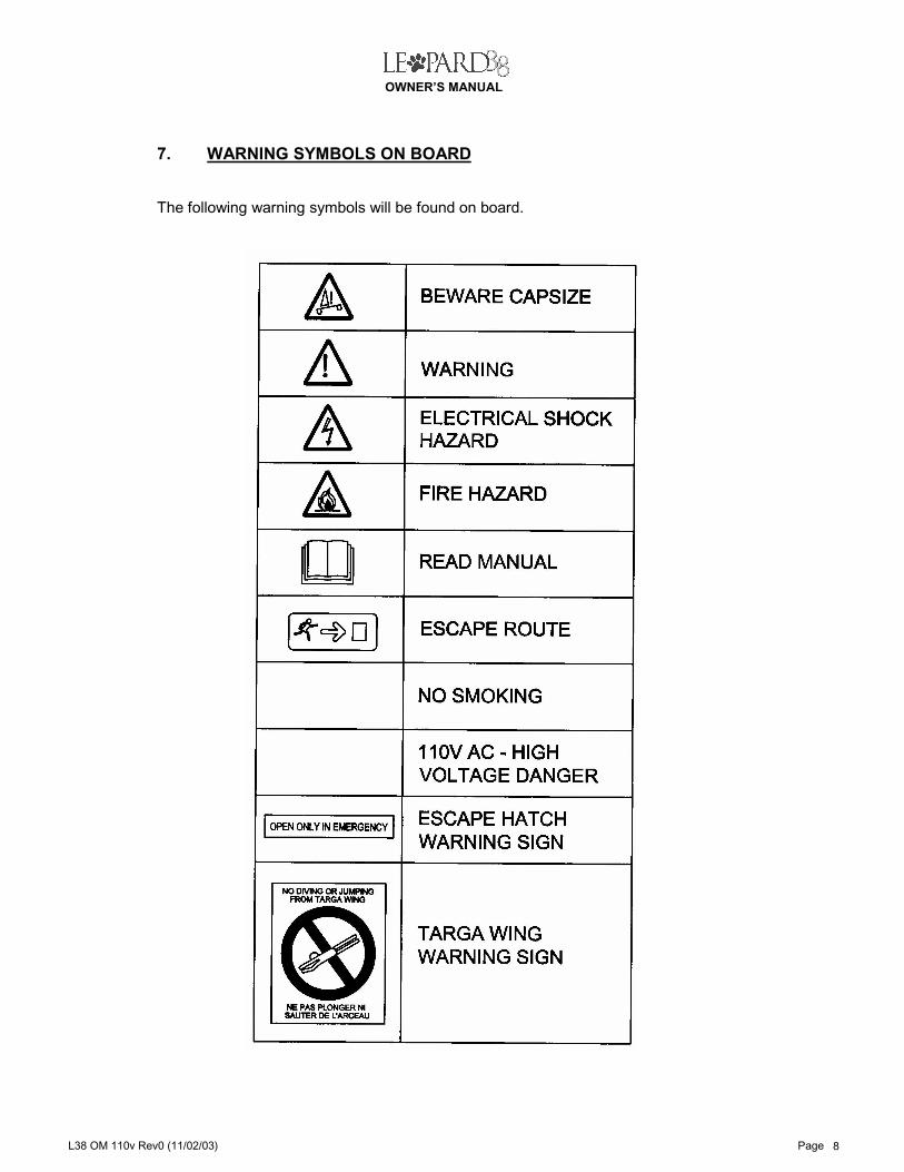
7. WARNING SYMBOLS ON BOARD The following warning symbols will be found on board.

OWNER’S MANUAL
L38 OM 110v Rev0 (11/02/03) Page 9
WARNING!
8. PREVENTION OF CAPSIZE SAILING MULTI-HULLS MAY BE CAPSIZED IF INCORRECTLY HANDLED. THE FOLLOWING PRECAUTIONS APPLY: 1. THE HELMSMAN MUST AT ALL TIMES BE AWARE THAT THE YACHT COULD
BE VULNERABLE TO CAPSIZE IN ROLL OR PITCH, AND OPERATE THE YACHT ACCORDINGLY.
2. EVEN IN CALM WATERS, SAIL SHOULD BE REDUCED ABOVE 20 KNOTS OF
WIND ALLOWING FOR GUSTS. 3. APPROPRIATE SAILS SHOULD BE CHOSEN TO SUIT THE PREVAILING WIND
AND SEA CONDITIONS. 4. EXERCISE CARE WHEN ALTERING COURSE FROM A FOLLOWING TO A
BEAM WIND AND IN BREAKING SEAS. 5. IT IS THE OWNER'S / OPERATOR'S RESPONSIBILITY TO ENSURE THAT
MOORING LINES, TOWING LINES, ANCHOR CHAINS AND ANCHORS ARE ADEQUATE FOR THE VESSEL'S INTENDED USE.
CAUTION: (a) THE BREAKING STRENGTH OF LINES / CHAINS SHALL NOT EXCEED 80%
OF THE THEORETICAL BREAKING STRENGTH OF THE RESPECTIVE STRONG POINT.
(b) THE OWNER / OPERATOR SHALL MAKE HIMSELF ACQUAINTED WITH THE SECURING OF THE TOWLINE ONBOARD ON THE DESIGNATED STRONG POINTS.
(c) ALWAYS TOW OR BE TOWED AT SLOW SPEED.
(d) WHEN MAKING TOW LINE FAST, AVOID TYING KNOTS OR LOOPS THAT CANNOT BE RELEASED UNDER LOAD.
OWNER’S MANUAL
L38 OM 110v Rev0 (11/02/03) Page 10
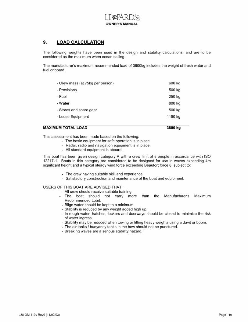
9. LOAD CALCULATION The following weights have been used in the design and stability calculations, and are to be considered as the maximum when ocean sailing. The manufacturer’s maximum recommended load of 3800kg includes the weight of fresh water and fuel onboard.
- Crew mass (at 75kg per person) 600 kg
- Provisions 500 kg
- Fuel 250 kg
- Water 800 kg
- Stores and spare gear 500 kg
- Loose Equipment 1150 kg
MAXIMUM TOTAL LOAD 3800 kg This assessment has been made based on the following:
- The basic equipment for safe operation is in place. - Radar, radio and navigation equipment is in place. - All standard equipment is aboard.
This boat has been given design category A with a crew limit of 8 people in accordance with ISO 12217-1. Boats in this category are considered to be designed for use in waves exceeding 4m significant height and a typical steady wind force exceeding Beaufort force 8, subject to:
- The crew having suitable skill and experience. - Satisfactory construction and maintenance of the boat and equipment.
USERS OF THIS BOAT ARE ADVISED THAT:
- All crew should receive suitable training. - The boat should not carry more than the Manufacturer's Maximum
Recommended Load. - Bilge water should be kept to a minimum. - Stability is reduced by any weight added high up. - In rough water, hatches, lockers and doorways should be closed to minimize the risk
of water ingress. - Stability may be reduced when towing or lifting heavy weights using a davit or boom. - The air tanks / buoyancy tanks in the bow should not be punctured. - Breaking waves are a serious stability hazard.
OWNER’S MANUAL
L38 OM 110v Rev0 (11/02/03) Page 11
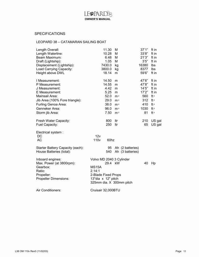
SPECIFICATIONS LEOPARD 38 – CATAMARAN SAILING BOAT Length Overall: 11.30 M 37’1” ft in Length Waterline: 10.28 M 33’8” ft in Beam Maximum: 6.48 M 21’3” ft in Draft (Lightship): 1.05 M 3’5” ft in Displacement (Lightship): 7430.0 kg 16380 lbs Load Carrying Capacity: 3800.0 kg 8377 lbs Height above DWL 18.14 m 59’6” ft in I Measurement: 14.50 m 47’6” ft in P Measurement: 14.55 m 47’8” ft in J Measurement: 4.42 m 14’5” ft in E Measurement: 5.25 m 17’2” ft in Mainsail Area: 52.0 m² 560 ft² Jib Area (100% Fore triangle): 29.0 m² 312 ft² Furling Genoa Area: 38.0 m² 410 ft² Genneker Area: 96.0 m² 1030 ft² Storm jib Area: 7.50 m² 81 ft² Fresh Water Capacity: 800 ltr 210 US gal Fuel Capacity: 250 ltr 65 US gal Electrical system : DC 12v AC 110v 60hz Starter Battery Capacity (each): 95 Ah (2 batteries) House Batteries (total): 540 Ah (3 batteries) Inboard engines: Volvo MD 2040 3 Cylinder Max. Power (at 3800rpm): 29.4 kW 40 Hp Gearbox: MS15A Ratio: 2.14:1 Propeller: 2-Blade Fixed Props Propeller Dimensions: 13"dia x 12" pitch 325mm dia. X 300mm pitch Air Conditioners: Cruisair 32,000BTU

OWNER’S MANUAL
L38 OM 110v Rev0 (11/02/03) Page 12
10. ECOLOGICAL / OPERATIONAL ASPECTS AS OUR ENVIRONMENT IS VERY FRAGILE WE MUST PLEDGE OURSELVES IN WHATEVER WE DO TO PROTECT IT FOR THE FUTURE. ENVIRONMENT PROTECTION The following are some general points: 1. Do not use excessive speed when under power; minimize noise and exhaust
pollution.
2. Prevent all spillage of oil or fuel into the sea. Always check the bilge water prior to pumping it overboard.
3. Toilets must not be pumped out into the sea within 12 nautical miles of the shore.
4. Always use ecologically sensitive consumables and cleaning materials.
5. Never throw any waste products into the sea.
6. Use ecologically sensitive paints and dispose of excess and waste in accordance with local regulations.
MAINTENANCE You should ensure that your yacht is maintained to a high standard for your safety and for protection of the environment. 1. Carry out the recommended maintenance tasks as specified in the manufacturer's
handbooks supplied with the boat.
2. Always use the manufacturer's recommended consumables (oils, etc.) and spares supplied by the manufacturer.
3. When equipment is not in use, protect it from deterioration.
OPERATIONAL Always be aware of the danger of fire and flood and be prepared to take the necessary action. FLOODING 1. Keep HATCHES and PORTLIGHTS closed at sea.
2. Keep the bilges dry and check them regularly for water and oil.
3. Keep all bilge pumps and suction areas clean and serviceable.

OWNER’S MANUAL
L38 OM 110v Rev0 (11/02/03) Page 13
FIRE 1. NEVER HAVE UNCONTROLLED FLAMMABLE PRODUCTS ON BOARD.
2. ALWAYS HAVE FIRE EXTINGUISHERS SERVICED AND AVAILABLE.
3. ENSURE THAT ALL ESCAPE ROUTES ARE ACCESSIBLE.
4. The boat owner / operator shall:
- Have fire-fighting equipment checked at intervals indicated on the equipment. - Replace portable fire fighting equipment, if expired or discharged, by devices of
identical or greater fire-fighting capacity. - Have fixed systems refilled or replaced when expired or discharged.
5. Keep the bilges clean and check for fuel and gas vapours or fuel leaks at regular intervals.
6. When replacing parts of the fire-fighting installation only matching components shall be used, bearing the same designation or being equivalent in their technical and fire resistant capabilities.
7. Do not fit free hanging curtains or other fabrics in the vicinity of or above cookers or other open flame devices.
8. Do not stow combustible material in the engine spaces. If non-combustible materials are to be stowed in the engine space they must be secured against falling into machinery and shall cause no obstruction to access to the engines or engine spaces.
9. NEVER:
- Obstruct passageways to exits and hatches.
- Obstruct safety controls; e.g. fuel valves, gas valves and switches of the electrical system.
- Obstruct portable fire extinguishers stowed in lockers.
- Leave the craft unattended when cooking and / or heating appliances are in use.
- Use gas lights in the craft.
- Modify any of the craft's systems (especially electrical, fuel and gas) or allow unqualified personnel to modify any of the craft's systems.
- Fill any fuel tank or replace gas bottles when machinery is running or when cooking or heating appliances are in use.
- Smoke while handling fuel or gas.

OWNER’S MANUAL
L38 OM 110v Rev0 (11/02/03) Page 20
11. FIRE FIGHTING IT IS THE OWNER’S RESPONSIBILITY (OR IF ABSENT, THE PERSON WHO IS DEPUTISED, SUCH AS THE SKIPPER) TO ENSURE THAT EVERYONE ON BOARD KNOWS THE LOCATION OF THE FIRE FIGHTING EQUIPMENT AND THAT THE ESCAPE ROUTES ARE ACCESSIBLE. IT IS THE OWNER’S RESPONSIBILITY TO ENSURE THAT THE FIRE FIGHTING EQUIPMENT IS REGULARLY MAINTAINED AND OPERATIONAL AT ALL TIMES. The fire extinguishers and the escape hatches are shown on the drawing L38/8.0540/1028. Fire extinguishers are 5A34B dry powder and may be used on any fire. They are operated by: 1. Breaking the seal and removing the safety clip. 2. Directing the extinguisher at the base of the fire. 3. Squeezing the trigger. 4. The discharge range is 4 metres and the time 8 seconds. In the event of a fire in the engine room the emergency fuel shut off valves MUST be closed. The emergency fuel shut off valves are situated on top of the fuel tanks which are beneath the port and starboard passage floors. The fire may be extinguished from inside the port and starboard aft cabins via the fire ports located at the base of the engine room bulkheads. It is not advisable to open the deck hatches to the engines when extinguishing a fire.

OWNER’S MANUAL
L38 OM 110v Rev0 (11/02/03) Page 21
12. LIFERAFT STOWAGE The liferaft may be stowed in the locker in the cockpit floor. Refer drawing ref. L38/8.0540/1028. IT IS THE OWNER’S RESPONSIBILITY TO ENSURE THAT AN ACCREDITED AGENT OF THE LIFE RAFT MANUFACTURER SERVICES ANY LIFE RAFT WITHIN THE TIME ALLOWED BY THE MANUFACTURER OR THE NATIONAL AUTHORITY.

OWNER’S MANUAL
L38 OM 110v Rev0 (11/02/03) Page 23
13. GAS SYSTEM OPERATION The gas cylinders are situated in a self-draining locker on the starboard side of the cockpit, near the transom walk through. A gas line links the tanks to the stove and a solenoid valve shuts of the gas in the locker as shown in the drawing L38/4.5210/868. The “Gas Valve” breaker situated at the DC switch panel activates the solenoid. To use the stove, switch on the breaker. An orange pilot light will indicate that the system is on. The pressure gauge is to check for leaks and is situated in the gas locker. IT SHOULD BE NOTED THAT GAS SYSTEMS ARE A POTENTIAL HAZARD UNLESS OPERATED PROPERLY. The following should be adhered to:
1. Test the LPG system for leakage regularly. Check all connections for leakage by: - Observing the pressure gauge for pressure drop with all appliances valves
closed, and cylinder valve opened, and then closed. - Manual leak testing. - Testing with soapy water or detergent solution (with appliance-burner valves
closed and cylinder and systems valves open).
2. If leakage is present, close the cylinder valve and have the system repaired before further use. A competent person should make system repairs.
3. CLOSE THE MANUAL VALVES WHEN THE GAS IS NOT IN USE.
4. IN AN EMERGENCY, CLOSE THE MANUAL VALVES ON THE BOTTLES. DO NOT RELY ON THE SOLENOID VALVE.
5. Make sure the valves on the stove are closed before opening the manual valves and the solenoid valve.
6. NEVER USE A FLAME TO FIND A LEAK.
7. Ammonia can corrode copper. Do not use a solvent or a liquid containing ammonia on the copper pipes or a leak may occur at a joint.
8. WHEN A GAS APPLIANCE IS IN USE IT BURNS UP OXYGEN AND GIVES OFF OTHER GASES SUCH AS CARBON MONOXIDE. THERE MUST BE ADEQUATE VENTILATION WHEN GAS-BURNING APPLIANCES ARE USED.
9. Keep the valve closed on empty cylinders. Empty cylinders must be left in the locker or on deck.
10. DO NOT STOW ANYTHING ELSE IN THE GAS CYLINDER LOCKER.
11. Propane gas is to be used and may be used between – 35 and + 50 C.
12. NEVER LEAVE GAS APPLIANCES IN OPERATION OR GAS CYLINDER MASTER VALVES OPEN WHEN NO ONE IS ON BOARD.
13. DO NOT SMOKE WHEN CHANGING BOTTLES.
14. GAS CYLINDERS SHOULD BE CHECKED ANNUALLY AND SHOULD BE CHANGED IF DAMAGED OR CORRODED.
15. THE GAS REGULATOR IS PRE-SET AND SHOULD NOT BE TAMPERED WITH. A QUALIFIED GAS TECHNICIAN SHOULD CHECK IT ANNUALLY.

OWNER’S MANUAL
L38 OM 110v Rev0 (11/02/03) Page 27
14. BILGE PUMP OPERATION. The bilge pump system is shown on the accompanying drawing L38/4.4800/867. There are six pumps:
- One manual bilge pump in each keel sump - One electrical bilge pump in each keel sump - One electrical bilge pump in each engine room
The manual pumps are operated from the passageway at the base of the stairways alongside the toilet compartments. The pump handles are stowed next to the stairways. The electric bilge pumps are wired directly to the house batteries via float switches and will operate whenever there is sufficient fluid in the sumps. When operating, a warning light will come on at the helmstation and DC panel. The electric bilge pumps in the keel sumps may be operated from the DC switch panel, in which case the warning lights will not come on. CARE SHOULD BE TAKEN TO ENSURE THAT THE BILGES ARE OIL AND FUEL FREE TO AVOID POLLUTION, AND THAT NO LOOSE MATERIAL IS SUCKED INTO THE PUMP. .

OWNER’S MANUAL
L38 OM 110v Rev0 (11/02/03) Page 29
15. TOILET OPERATION Refer to schematic drawing L38/4.4800/866. THERE SHALL BE NO DISCHARGE OF WASTE INTO THE SEA WITHIN 12 NAUTICAL MILES OF THE SHORE. The toilet system is arranged so that the toilets are pumped into a holding tank. If the holding tank discharge seacock (positioned under the aft step of the corridor steps) is open, the tank gravity drains overboard. If this valve is closed, waste is stored in the holding tank. The holding tank can be emptied by draining overboard (NOT WITHIN 12NM LIMIT) or by using a dockside pump-out connected to the deck pump-out waste fitting. The capacity of the tank is 70 litres each side. The flushing is 2 litres per flush, which gives 35 flushes per side. Indicator lights will show on the control board when the tank is full. The holding tanks may be flushed. If cleaning is required only use ecologically friendly materials.

OWNER’S MANUAL
L38 OM 110v Rev0 (11/02/03) Page 33
16. FRESH WATER SYSTEM OPERATION
Refer to schematic drawing l38/4.4800/864 & L38/4.4800/869. Two tanks (2 x 400Lltr capacity each) are situated in the foredeck lockers and can be filled directly through filler cap situated on each tank. A separate valve controls each tank and is marked according to which tank it controls. All valves, pumps & switches are situated on the Water Pump Board under the galley sink. 1. To Use Water:
1.1. Turn on the “Fresh Water Pump” breaker at the DC switch panel. Open the faucet. The pump will start running and only stop once the faucet is closed and the system is pressurised, which could take approximately a minute for the first time.
1.2. If the pump keeps running, the following problems may exist: - A tank has run dry. - A leak has developed in the system, i.e., a faucet could be open.
2. Switch from an empty tank to a full one:
2.1. Leave the pump on and open the bleed valve. 2.2. Close valve of empty tank. 2.3. Open valve of full tank until there is a steady flow of water (approx. 15
seconds). 2.4. Close bleed valve. The pump will run until adequate pressure has been
restored (1-2 minutes). 2.5. If the pump fails to shut off repeat steps 2.3 and 2.4.
3. Should one pump fail, there is a second pump as a back-up. To change pumps:
3.1. Turn off the “Fresh Water Pump” breaker at the DC switch panel. 3.2. Locate the Water Pump Board under the galley sink. 3.3. Locate the toggle switch between the pumps, and change the position of
the switch from “1” to “2”. 3.4. Rotate both pump selection valves from position “1” to position “2”. 3.5. Turn on the water pressure and bleed the system as previously described.

OWNER’S MANUAL
L38 OM 110v Rev0 (11/02/03) Page 34
17. STEERING Refer drawing L38/8.054/1023. Steering is by wheel, with cables linked to the steering tie bar, which is connected to the tiller arms. The steering stop pads prevent the rudders being over-rotated. In the event of the steering system failing, an emergency tiller may be fitted on to the head of the starboard rudder stock. This can be accessed through a deck plate that is situated on the starboard transom steps. In heavy seas a block and tackle may be rigged on to the emergency tiller.

OWNER’S MANUAL
L38 OM 110v Rev0 (11/02/03) Page 40
18. ENGINE ROOM CAREFULLY READ THE ENGINE OPERATOR’S MANUAL. The engine room layout is shown in the drawing (L38/4.4030/958). The engine is operated by the controls at the helmsman’s position and has an emergency stop pull cable. The engines are used to heat the port and starboard hot water cylinders. ENGINE VENTILATION
Engine room ventilation as shown on the drawing L38/4.4030/982. Before an engine is started the blower should be operated for about 5 minutes. If a smell of diesel still persists at the exhaust vent, the source of the smell should be investigated in engine room. ENGINE FUEL
The engine fuel system is shown on the drawing L38/4.4030/870. Fuel can be drawn from both the port and starboard tanks. The fuel/water separator should be checked regularly particularly after fuelling, heavy seas etc. In the event of water being found in the fuel/water separator the fuel tank should be allowed to settle and water drawn off at the tank drain. IN THE EVENT OF A FIRE IN THE ENGINE ROOMS, THE FUEL SHUT OFF VALVES ON THE FUEL TANKS MUST BE CLOSED. THE FUEL TANKS ARE POSITIONED UNDER THE PORT AND STARBOARD CORRIDOR FLOORBOARDS AS SHOWN ON THE DRAWING.
ENGINE EXHAUST
The engine exhaust system is shown on the drawing L38/8.0540/1025. It passes through a water trap before being discharged overboard. Attention should be paid to the exhaust with respect to the condition and the load on the engine. Black smoke indicates an overload. PROPELLER
A. THE ENGINE SPEED TO BE REDUCED BEFORE GOING FROM FORWARD TO REVERSE OR VICE VERSA.
B. PROPELLERS MUST BE INSPECTED ON DELIVERY COMPLETION, PROP-NUTS MUST BE TORQUED TO 200FT LB.
The propellers should be checked regularly. The anodes should be checked at least every month to ensure that they are firmly secured. During this check the propeller retaining nuts should be tightened. Anodes must be replaced if excessively corroded. Failure to do this will result in the propellers and shaft corroding.
OWNER’S MANUAL
L38 OM 110v Rev0 (11/02/03) Page 46
19. ELECTRICAL SYSTEM – DC The DC electrical system is 12v. The layout and controls are shown on the accompanying drawings. The following precautions should be applied: 1. Always check the batteries and their state of charge before sailing.
2. Before sailing, check that the navigation lights are working and that spare bulbs are on board.
3. NEVER WORK ON ANY ELECTRICAL ITEM WHEN IT IS IN USE OR POWER TO IT IS SWITCHED ON.
4. NO ELECTRICAL ITEM OR CABLE SHOULD BE MODIFIED UNLESS BY A QUALIFIED MARINE ELECTRICIAN.
5. NEVER CHANGE THE CAPACITY OF A FUSE OR BREAKER.
6. NEVER INSTALL NEW EQUIPMENT, WHICH HAS A GREATER RATING THAN ITS PREDECESSOR DOES.
7. NEVER LEAVE THE VESSEL UNATTENDED WITH POWER ON, EXCEPT FOR THE BILGE PUMPS.
BATTERY OPERATION.
The engine batteries are situated in their respective engine rooms, and the house batteries are situated in the saloon seat locker. The house battery switches are under the chart table. There is one (+) positive and one (-) negative battery switch to connect the house batteries. These should be left on at all times while the yacht is occupied, AND SWITCHED OFF IN THE EVENT OF AN ELECTRICAL FIRE! The engine battery switches are situated in the hanging lockers of the port and starboard aft cabins.
NEVER TOUCH EITHER THE POSITIVE (+) OR NEGATIVE (-) SWITCHES WHILE THE ENGINES ARE RUNNING.
When leaving the yacht both house battery switches and engine starter battery switches should be in the 'off' position. WINDLASS OPERATION. The windlass breaker is situated under the chart table, above the battery switches.
The windlass will only operate when the port engine is running.
To operate the windlass:
1. Start port engine. 2. Check that the windlass breaker under the switch panel is on. 3. Switch on at the windlass remote control. 4. Press the “UP” or “DOWN” buttons as required.

OWNER’S MANUAL
L38 OM 110v Rev0 (11/02/03) Page 52
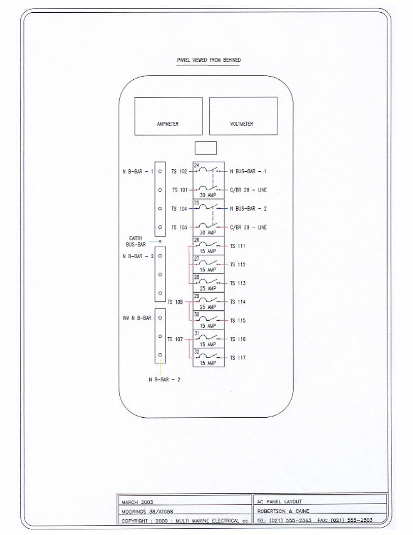
20. ELECTRICAL SYSTEM AC The AC electrical system is 110v 60hz and is as shown on the layout and panel drawings.
The system represents a potential hazard and the following precautions must be applied:
1. The AC system is a double polarity and the wiring colour is brown.
2. NEVER WORK ON THE ELECTRICAL SYSTEM UNLESS POWER IS SWITCHED OFF. REMEMBER THIS IS A TWO-WIRE SYSTEM AND THAT FULL ISOLATION IS NECESSARY.
3. DO NOT MODIFY THE CRAFT'S ELECTRICAL SYSTEMS OR RELEVANT DRAWINGS. ONLY A COMPETENT MARINE ELECTRICAL TECHNICIAN SHOULD PERFORM INSTALLATIONS, ALTERATIONS AND MAINTENANCE. INSPECT THE SYSTEM AT LEAST BI-ANNUALLY.
4. DISCONNECT SHORE-POWER CONNECTIONS WHEN THE SYSTEM IS NOT IN USE.
5. NEVER INSTALL A REPLACEMENT ITEM OF HIGHER POWER THAN ITS PREDECESSOR.
6. USE WHERE POSSIBLE, DOUBLE INSULATED EQUIPMENT OR AS A MINIMUM, EQUIPMENT WITH AN EARTH.
7. CONNECT METAL PARTS OF ELECTRICAL EQUIPMENT WITH A YELLOW/GREEN EARTH WIRE.
8. SHUT OFF THE AC POWER BEFORE LEAVING THE YACHT.
SHORE CONNECTION
WARNING! DO NOT ALLOW THE SHORE-POWER CABLE TO HANG IN THE WATER. AN ELECTRICAL FIELD CAN BE CAUSED WHICH CAN CAUSE INJURY OR DEATH TO NEARBY SWIMMERS. WARNING! To minimize shock and fire hazards: - Turn off the craft's shore-power connection switch before connecting to shore-power
source. - Connect shore-power cable to craft's inlet before connecting to shore-power source. - Disconnect shore-power cable at shore-power source first. - Close shore-power inlet tightly. - Do not alter shore-power cable connectors. Use only compatible connectors.

OWNER’S MANUAL
L38 OM 110v Rev0 (11/02/03) Page 53
21. FREEZER OPERATION
The freezer/refrigeration unit is an air- cooled, 12V DC system. The compressor unit is located in the port hull aft lazarette and is accessed via the swim platform lazarette hatch. The freezer unit in the galley is divided into two compartments. The holding plate is in the freezer compartment and the adjacent compartment is the refrigerator. The unit will freeze the holding plate from warm, but may take several hours depending on the ambient temperature and humidity. The unit will automatically operate if the thermostat is on and 12 volts DC is available. The system may be operated using AC shore power battery charger to maintain batteries. 1. To cool the freezer:
1.1. Check that the fridge/freezer breaker is on. 1.2. Check that there is AC power available from shore power. 1.3. Set the thermostat to the required setting. 1.4. The unit will then operate automatically. Running time depends
on ambient temperature and humidity.
2. To drain the Freezer box: 2.1 The drain plug is situated in the base of the freezer box. 2.2 Remove the plug and drain the box.
22. AIR-CONDITIONING
It is recommended that you study the Operator’s Manual in order to operate the air-conditioning system. Before the air-conditioning system can be operated, the vessel must be moored at a marina and the shore-power cable connected. This vessel has a shore-power only air-conditioning system.

OWNER’S MANUAL
L38 OM 110v Rev0 (11/02/03) Page 54
23. LAY-UP AND WINTERISATION In the event of the vessel being laid up for any length of time (+/- 2 months or more) particularly in cold weather, the following must be done: 1. Remove the batteries for temperate storage.
2. Ensure all the water systems are drained.
3. Open up bilge covers and floorboards for surveilance.
4. Ensure antifreeze is in the engine cooling systems.
5. Check that all seacocks are closed.
6. Empty the fresh water tanks.
7. Leave torches, fire extinguishers and pump handles positioned for easy access.
8. Ensure that the vessel, and particularly the bilges, are checked regularly.
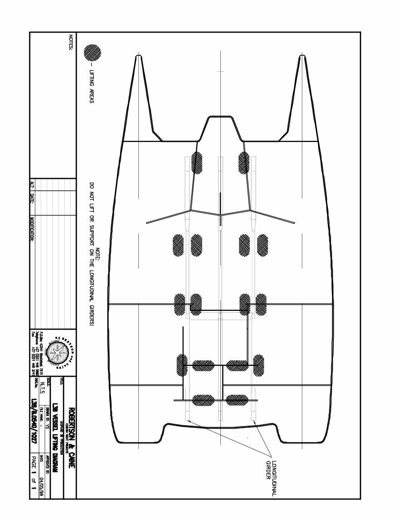
24. HULL TRANSPORT In the event of the hull being lifted, slings should be placed at the bulkheads and adjusted for length to ensure the vessel lifts horizontally. The yacht may be docked on its keels but must be adequately supported in cradles fore and aft of the keels. For transportation the yacht should be supported as shown in drawing L38/8.0540/1027. DO NOT SUPPORT THE YACHT ON THE BRIDGEDECK GIRDERS

OWNER’S MANUAL
L38 OM 110v Rev0 (11/02/03) Page 55
25. GENERAL CLEANING AND MAINTENANCE The intention of the section is to indicate areas that should be inspected regularly to ensure the efficient and safe operation of the vessel. In all cases the instructions given in the supplied equipment manuals must be followed in order to maintain the warranty / guarantee of the specific item.
• The Vessel is manufactured in accordance with the European Recreational Craft Directive 94/25/EC and is CE Certified in design category A.
• For technical details and operating instructions refer to the relevant
sections of this Owners Manual and the specific equipment instruction manual
CLEANING
The following is a summary of the cleaning methods and materials recommended by or prohibited for use by Robertson & Caine. We recommend the use of 3M™ Marine’s Reconditioning and Maintenance Products. These products are specifically designed for fiberglass boats used in the marine environment. The use of the following recommended 3M™ marine products will help maintain your boat to the highest standards.
• 3M™ Marine Multi-Purpose Boat soap • 3M™ Marine Protective Liquid Wax • 3M™ Marine Ultra Performance Paste Wax • 3M™ Marine Clean & Shine Wax • 3M™ Marine Metal Restorer and Polish • 3M™ Marine Outdoor Vinyl Cleaner, • Conditioner & Protector • 3M™ Marine Aluminium Restorer & polish
A. INTERIOR AND EXTERIOR GRP SURFACES
To maintain the factory new appearance of the boat all fibreglass surfaces should be cleaned regularly. Normal accumulations of surface dirt should be removed by simply rinsing with fresh water. The exterior deck surfaces should be rinsed down with fresh water after every trip to prevent the build up of crystallized salts. To remove dirt, grease and oil use 3M™ Marine Multi Purpose Boat Soap. Following the manufacturer’s directions for mix ratios and application instructions. Exterior fibreglass surfaces should be waxed twice a year with 3M™ Marine Protective Liquid Wax or 3M™ Marine Ultra Performance Paste Wax to protect against Ultra Violet degradation (chalking) and to maintain a deep shine on the exposed surfaces. Apply according to the manufacturers instructions recommended for each product. To maintain and enhance the shine between wax applications apply 3M™ Marine Clean and Shine Wax after each washing, this product can be simply sprayed on and then wiped off.

OWNER’S MANUAL
L38 OM 110v Rev0 (11/02/03) Page 56
B. ACRYLIC PORTLIGHTS, WINDOWS & HATCHES
1. First rinse off with fresh water and then wash all Portlights, windows and hatches with 3M™ Marine Multi Purpose Boat Soap, use a clean soft cloth and apply only light pressure. Rinse with clean fresh water and dry by blotting with a slightly damp cloth or chamois.
2. Never use window cleaning sprays, scouring materials or solvents such as
Acetone, Benzene or Lacquer Thinners on acrylic materials 3. If masking tape is put on to acrylic material it must be removed as soon as
practicable as the glue could cause dulling of the acrylic surface. 4. Acrylic materials can be polished to a high grade finish and slight scratches
removed. We recommend the use of McGuire’s Mirror Glaze No. 17. Polishing should be done by hand as excess heat generated from machine polishing could cause distortion of the acrylic material and subsequent water leaks.
C. VINYL, UPHOLSTERY FABRICS AND CARPETING
1. All interior vinyl, upholstered panels and carpeting should be regularly cleaned. Any spills should be cleaned immediately to prevent possible permanent staining. The carpets should be regularly vacuumed to remove dirt before it becomes trodden in to the material.
2. Regular cleaning with 3M™ Marine Multi Purpose Boat Soap diluted as per
the manufacturer’s instructions is recommended. To remove stubborn marks and stains moderate scrubbing with Scotch Brite™ No.63 Cleansing Sponge will loosen the mark or stain. This must be tested on a sample of material before commencing to use in visible areas. To restore and protect vinyl apply a coat of 3M™ Marine Outdoor Vinyl Cleaner, Conditioner and Protector. This will build up a barrier against normal dirt and stains and will retard UV damage.
THE FOLLOWING MATERIALS MUST NEVER BE USED ON ANY VINYL, UPHOLSTERED PANEL, CARPETING or FIBREGLASS SURFACE:
• Household bleach or any cleaning agent containing bleach. • Household cleaners containing ammonia • Alkaline cleaners • Washing soda • Caustic Soda • Abrasive cleaners • Hydrogen peroxide • Acetone • Acetate thinners • Scouring pads
3 o

OWNER’S MANUAL
L38 OM 110v Rev0 (11/02/03) Page 57
D. ELECTRICAL SYSTEMS
The batteries, terminals and cables should be inspected on a regular basis for signs of damage, corrosion, cracks and electrolyte leakage. Battery terminals should be kept clean, tightly connected, greased and protected from accidental short circuiting. Refer to separate instructions in the Owners manuals including wiring diagrams. E. PLUMBING SYSTEMS
1. All pumps and float switches should be checked frequently to ensure proper operation. This is an especially important regular maintenance item since the proper functioning of a pump could save the vessel from serious damage in the future.
2. Inspect all hoses for chafing and damage. Ensure that all hose clamps are tight. Check that all pump impellers are clean and free of obstructions.
3. Inspect electrical wiring for corrosion and ensure that float switches move freely and are operational
4. Make sure that the manual bilge pump handles are available and securely located in the mounting brackets provided.
F. WINCH MAINTENANCE
Follow the maintenance instructions specified by the winch manufacturer. The winch should be cleaned and lightly greased annually.
G. DECK HARDWARE AND STAINLESS STEEL
1. Check all fittings regularly to make sure that all screws are tight.
2. Occasionally lubricate moving parts such as blocks, turnbuckles, locking cleats, snatch blocks and track slides.
3. Inspect Mooring cleats and fairleads for secureness and tighten as necessary. If cleats or fairleads are damaged or worn they should be replaced.
4. Damaged or missing cotter pins in turnbuckles or shackles should be replaced.
5. The majority of hardware and fittings installed on the boat are made of stainless steel. To maintain the original shine and help prevent corrosion regular rinsing with fresh water and washing with 3M™ Marine Multi Purpose Boat Soap is necessary.
6. In cases of surface rust, oxidation and tarnishing of the metal surface the use of 3M™ Marine Metal Restorer and polish will restore the original luster and protect against future surface defects.
7. Never use coarse abrasives like sandpaper or steel wool as these may actually cause rust and corrosion.
8. Never clean with acids, cleaning materials containing bleaches or ammonia and leave any stainless steel in contact with iron, steel or other metals which can cause surface contamination.

OWNER’S MANUAL
L38 OM 110v Rev0 (11/02/03) Page 58
H. RIGGING
1. Rigging is subject to Fatigue and wear and must be carefully inspected and maintained. A regular inspection for Wear, discoloration, loose wires and chafing should be conducted. The frequency should be determined by the usage of the vessel.
2. Always rinse the rigging with fresh water after sailing. Salt deposits can create corrosion pitting, cracking & general deterioration.
3. Clean rigging with CHLORINE free water soluble detergent and non abrasive cleaning equipment.
4. Inspect rigging for stains; Rust stains can indicate areas of stress corrosion or cracking. Remove stains with Synthetic or brass pads, never use steel wool.
5. Inspect for broken wires and replace as necessary.
6. Do not mix Stainless steel and Galvanised metals on cables, fittings, AND PINS etc. Mixing dissimilar metals will cause rapid deterioration due to the effects of electrolysis.
7. If rigging is removed for any reason it must be stored in a dry place never in plastic bags or plastic wrapping.
I. ELECTROLYSIS AND GALVANIC PROTECTION
1. Salt water allows electric current to flow from anodic to cathodic materials. The relative position of two metals on the Galvanic table determines which material (the Anode) will lose material and which will remain largely unchanged (the Cathode).
2. The rate of wear is determined by the distance the two metals are apart on the galvanic table. For this reason sacrificial Zinc anodes are fitted to the propeller shaft of each engine to attract any stray electrical current away from the Bronze propellers and Stainless Steel propeller shafts.
3. The rate of electrolysis and therefore the speed at which the sacrificial anodes deteriorate varies greatly and is affected by amongst other things the quality of the water, the amount of galvanic protection on boats berthed in the immediate vicinity of the vessel.
4. Any work being done i.e. welding on surrounding boats will greatly increase the risk of electrolysis.
5. The risk of galvanic corrosion is greatly increased if any surrounding boats are connected to shore power and they have any neutral or ground faults in their electrical wiring systems.
6. Your vessel is protected to the highest standards and as long as the
sacrificial anodes are inspected regularly (minimum every 3 months) and replaced as required no problems should be experienced.

OWNER’S MANUAL
L38 OM 110v Rev0 (11/02/03) Page 59
J. ENGINES
1. Refer to the Lubrication and servicing instructions in the engine manufactures operating manual.
2. A regular visual inspection of all engine fittings, pipes and wiring must be carried out. Any signs of wear, Chafing or loose parts must be corrected.
3. Also check the tightness and wear on all engine belts and replace if necessary.
K. ROUTINE MAINTENANCE
1. Routine maintenance should include items based on how frequently the vessel is used i.e. (Engine hours) and on calendar dates i.e. (EXPIRY dates of Flares and servicing of fire extinguishers).
2. Other items to be checked on a regular basis include Oil level, Oil & Fuel Filters.
3. The operation of seacocks and valves should be inspected to ensure free and easy operation in case of emergency.
4. The gas system pipes and fittings should also be regularly checked for wear and tightness.
5. It is recommended that the checklists for routine maintenance found in the Owners Manual be used as a basis for a regular routine maintenance plan and include them as part of the ships log.
L. SAILS
1. Check all sails regularly for chafe and wear especially where they can contact deck fittings or rigging, at reef points, batten sleeves and the foot of the head sail.
2. Sail batten pockets should be inspected regularly especially where they can chafe against the shrouds
3. Sails should be protected when they are not in use from the effects of Ultra Violet radiation.
4. Mildew can be prevented by hand washing the sails with mild soapy water and drying before storage.
5. Regular inspection of running rigging, halyards, sheets and reef lines for chafe and damage is recommended.
6. Replace any damaged or chafed lines as required.

OWNER’S MANUAL
L38 OM 110v Rev0 (11/02/03) Page 60
M. ANTI-FOULING
1. The vessel has been painted with Petit Trinidad anti fouling in accordance with the manufacturers recommended application procedures.
2. The anti fouling should be checked on a regular basis and repaired or recoated as required depending on usage, storage and possible damage.
3. The use and compatibility of a different type of anti fouling paint over the existing coating should be checked with the manufacturer prior to application.
4. The anti fouling must be applied in accordance with the manufactures instructions and no guarantees can be given by Robertson & Caine
5. Under no circumstances must the hull be sanded, ground or have any form of abrasive preparation which could void the anti osmosis guarantee.
N. STORAGE AND WINTERIZATION
1. If the vessel is to be taken from the water and stored for any extended period then the following must be applied
2. The vessel must be lifted and supported as indicated in the relevant section of the owners manual and shown on the lifting, transport and storage drawings
3. The sails should be removed, cleaned, dried, correctly folded and stored in a dry well ventilated area.
4. Disconnect and remove batteries.
5. All cushions and mattresses should be removed and stored in a clean dry area. If this is not possible then they should be stored vertically on the boat to allow adequate air flow around the cushion and prevent mildew
6. If the vessel is to be stored in areas subject to Ice and snow then tenting or shrink wrapping the deck will prevent ice build up from damaging the hatches and portlights
7. In cold areas ensure that the engine coolant water is drained or contains anti freeze.

OWNER’S MANUAL
L38 OM 110v Rev0 (11/02/03) Page 61
25. OWNER’S INSTRUCTION MANUALS Book 1
1. VOLVO DIESEL ENGINES
2. MORSE CONTROL SYSTEM
3. VOLVO PENTA STERN SEAL
4. RACOR FUEL FILTER
5. LOFRANS WINDLASS
6. LEWMAR WINCH
7. PLASTIMO LIFERAFTS
8. FORCE 10 COOKER (2 BURNER)
9. CLARION AM/FM CD PLAYER
10. BOSE SPEAKERS
11. SEAFROST TRADEWINDS
12. ZINC SAVER
13. VDO AMMETER
14. VDO FUEL GAUGE
15. ATWOOD WATER HEATER
16. SENTRY BATTERY CHARGER
17. RULE BILGE PUMP
18. WHALE BILGE PUMP
19. JABSCO TOILETS
20. JABSCO ELECTRIC DRAIN PUMPS
21. CRUISAIR AIR-CONDITIONING BOOK 2 22. OWNER’S MANUAL
23. WHITLOCK STEERING
24. RAYTHEON INSTRUMENTS: ST60 TRIDATA ST60 WIND INSTRUMENT ST7001 + AUTOPILOT TYPE 150/400 RAYCHART 425 CHARTPLOTTER
25. RAY 215 VHF RADIO
26. PLASTIMO COMPASS
27. AQUASIGNAL NAVLIGHTS
28. WARRANTIES

OWNER’S MANUAL
L38 OM 110v Rev0 (11/02/03) Page 62
26. INDEX OF DRAWINGS
DRAWING NO. DRAWING TITLE
REV. DATE
REFERENCE SECTION
1. L38/4.4800/1020 SAIL PLAN 13/04/99
2. L38/4.4800/1021 SIDE ELEVATION 13/04/99
3. L38/4.4800/1022 DECK ARRANGEMENT 15/04/99
4. L38/4.4800/865 SEACOCK, VALVE & DRAIN LAYOUT 12/09/98
5. L38/4.4800/864 SYSTEMS LAYOUT 12/09/98
6. L38/8.0540/1026 FIRE PREVENTION AND SAFETY 15/04/99
7. L38/4.5210/868 GAS SYSTEM SCHEMATIC 15/04/97
8. L38/8.0540/977 UNDERWATER FITTINGS AND SEACOCKS 05/02/99
9. L38/4.4800/867 BILGE SYSTEM SCHEMATIC 14/09/98
10. L38/4.4800/866 TOILET AND HOLDING TANK SCHEMATIC 14/09/98
11. L38/4.4800/869 FRESH WATER SYSTEM 15/09/98
12. L38/8.0540/1023 STEERING SYSTEM -
13. L38/8.0540/1025 EXHAUST SYSTEM 15/04/99
14. L38/4.4030/1000 FUEL SYSTEM 22/02/99
15. L38/4.4030/982 (3 PAGES) ENGINE ROOM VENTILATION (3 PAGES) 22/01/99
16. L38/4.4030/958 (3 PAGES) ENGINE ROOM LAYOUT (3 PAGES) 22/02/99
17. L38/8.0540/1027 VESSEL LIFTING DIAGRAM 04/05/99
18. ELECTRICAL DWG AC PANEL LAYOUT 01/2003
19. ELECTRICAL DWG AC SCHEMATIC – 110Vac / 50Hz 01/2003
20. ELECTRICAL DWG DC PANEL LAYOUT 01/2003
21. ELECTRICAL DWG DC SCHEMATIC 01/2003
22. ELECTRICAL DWG SMALL CIRCUITS DIAGRAM 01/2003
23. ELECTRICAL DWG EQUIPMENT LAYOUT 01/2003
24. ELECTRICAL DWG LIGHTS / FANS CIRCUIT LAYOUT 01/2003
25. ELECTRICAL DWG TERMINAL STRIP LAYOUT 01/2003