
Kyland-USA, Kansas City, MO DYMEC is a registered trademark of Kyland-USA.
66
Kyland-USA, Kansas City, MO DYM EC K yland-U SA DYMEC is a registered trademark of Kyland-USA
-
Upload
beverly-greer -
Category
Documents
-
view
221 -
download
0
Transcript of Kyland-USA, Kansas City, MO DYMEC is a registered trademark of Kyland-USA.

Kyland-USA, Kansas City, MO
DYMEC
Kyland-USA
DYMEC is a registered trademark of Kyland-USA

Kyland-USA, Kansas City, MO
Kyland-USA Overview
• Kansas City, Missouri• ECO-Engineering Company• Veteran Owned Small Business • Made in USA products• Energy Conservation• Focus on IP Industrial Security

Kyland-USA, Kansas City, MO
DYMEC
Kyland-USA
DYMEC is a registered trademark of Kyland-USA
Fiber Optic Fundamentals

Kyland-USA, Kansas City, MO
Fiber Optics versus Copper Cabling
Optical fiber transmits via light pulsesCan be used for analog or digital transmission
Voice, computer data, video, etc.
Copper wires (or other metals) can carry the same types of signals with electrical pulses

Kyland-USA, Kansas City, MO
The Advantage of Fiber
Fiber has multiple advantages compared to metallic wires
* Bandwidth – more data per second
* Longer Distances
* Lighter and Smaller (Less Bulk)
* Faster Speeds – Terabyte Speeds Possible
Applications such as medical imaging and quantum key distribution are only possible with fiber because they use light directly

Kyland-USA, Kansas City, MO
Copper Wiring Tends to be Messy

Kyland-USA, Kansas City, MO
Optical Fiber versus Copper

Kyland-USA, Kansas City, MOFiber Optic Cables / Page 8
Fiber Optic Cable Structure
• Fiber is mechanically weak
• Cable adds protection and prevents physical damage during installation and use.
• Combination and quantity of protections and material as well as construction are strictly dependent on cable environment
Indoor
- Ducts- Trays- Building raiser- Plastic pipes- Raised floors- Plenum (US)
Outdoor
- Empty pipes- Ducts- Trays- Direct burial- Aerial

Kyland-USA, Kansas City, MO
Connectivity and Interoperability
ElectricalConnector Electrical
Connector
SFP Transceiver
SFP Transceiver
Fiber Optic Cable
LC OpticalConnector
LC OpticalConnector
OpticalPort
OpticalPort
Newer technologies involving higher datarates, smaller form factors, higher port densities, pluggability, and parallel links are
showing an increased need to focus on connectivity and interoperability issues
A failure anywhere along this link will cause the entire link to fail

Kyland-USA, Kansas City, MO
Copper is Slower / Limited DistanceWhat speed does each type support?
Cable Type Max Speed Max Distance Cost Factor
Category 5 100Mbs 100m 1x
Category 5e 1000Mbs 100m 1x
Category 6 1000Mbs 100m 1.3x
Category 6 10,000Mbs 57m 1.3x
Category 6a 10,000Mbs 100m 2x
Kyland-USA, Kansas City, MO
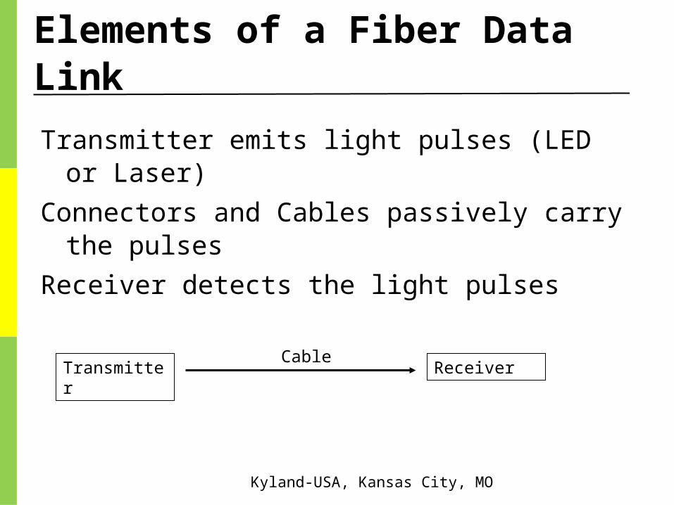
Elements of a Fiber Data Link
Transmitter emits light pulses (LED or Laser)
Connectors and Cables passively carry the pulses
Receiver detects the light pulses
Transmitter ReceiverCable

Kyland-USA, Kansas City, MO
Fiber Repeaters
For very long links, repeaters are needed to compensate for signal loss.
Fiber = Optical
Repeater = Electrical
Result = OEO (Optical – Electrical – Optical)
FiberRepeaterRepeater Repeater
Fiber FiberFiber

Kyland-USA, Kansas City, MO
Fiber Size & Aperture Comparisons

Kyland-USA, Kansas City, MO
Optical Fiber
CoreGlass or plastic with a higher
index of refraction than the cladding
Carries the signal
CladdingGlass or plastic with a lower
index of refraction than the core
BufferProtects the fiber from damage
and moisture
JacketHolds one or more fibers in a
cable

Kyland-USA, Kansas City, MO
Single-Mode Fiber
Single-mode fiber has a core diameter of 8 to 9 microns, which only allows one light path or mode
Index of refraction
Kyland-USA, Kansas City, MO
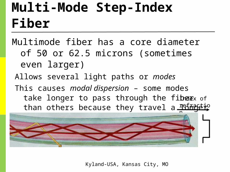
Multi-Mode Step-Index Fiber
Multimode fiber has a core diameter of 50 or 62.5 microns (sometimes even larger)
Allows several light paths or modes
This causes modal dispersion – some modes take longer to pass through the fiber than others because they travel a longer distance Index of
refraction

Kyland-USA, Kansas City, MO
Multi-Mode Graded-Index Fiber
The index of refraction gradually changes across the core
Modes that travel further also move faster
This reduces modal dispersion so the bandwidth is greatly increased
Index of refraction

Kyland-USA, Kansas City, MO
Step Versus Graded Index Fiber
Step index multi-mode was developed first, but rare today because it has a low bandwidth (50 MHz-km)
It has been replaced by Graded-index multi-mode with a bandwidth up to 2 GHz-km

Kyland-USA, Kansas City, MO
Plastic Optical Fiber
Large core (1 mm) step-index multi-mode fiber
Easy to cut and work with, but high attenuation (1 dB / meter) makes it useless for long distances
Kyland-USA, Kansas City, MOFiber Optic Cables / Page 20
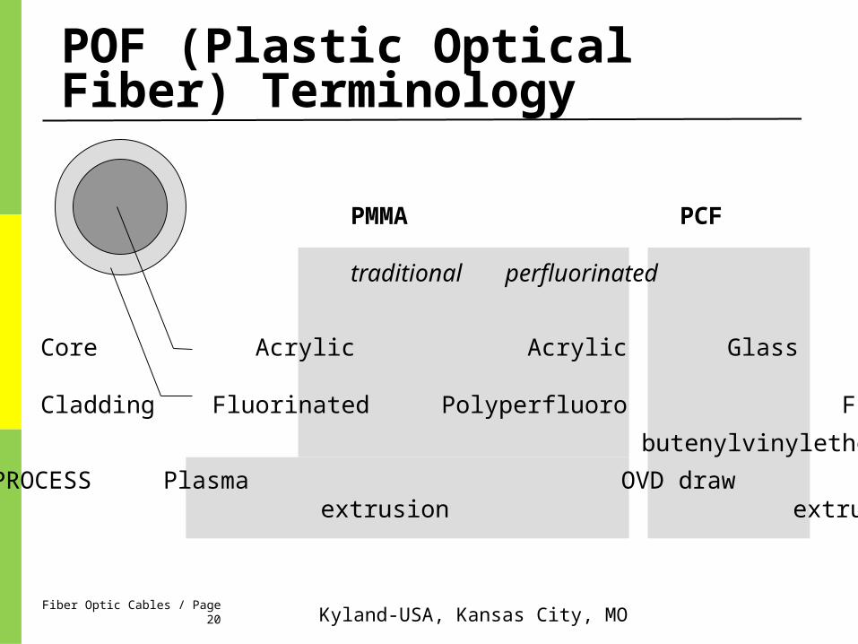
POF (Plastic Optical Fiber) Terminology
Core Acrylic Acrylic Glass
Cladding Fluorinated Polyperfluoro Fluorinated
butenylvinylether
PMMA PCF
traditional perfluorinated
PROCESS Plasma OVD draw extrusion extrusion

Kyland-USA, Kansas City, MOFiber Optic Cables / Page 21
Index profiles
PMMA Step Index
core = Constant refractive index
PMMA Graded Index
Core = several layer of material with different refractive indexes
Perfluorinated Polymer Graded index
Core = parabolic index
Kyland-USA, Kansas City, MOFiber Optic Cables / Page 22
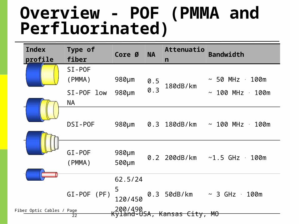
Overview - POF (PMMA and Perfluorinated)
Index
profileType of fiber Core Ø NA Attenuation Bandwidth
SI-POF
(PMMA)
SI-POF low NA
980µm
980µm
0.50.3
180dB/km~ 50 MHz . 100m
~ 100 MHz . 100m
DSI-POF 980µm 0.3 180dB/km ~ 100 MHz . 100m
GI-POF
(PMMA)
980µm
500µm0.2 200dB/km ~1.5 GHz . 100m
GI-POF (PF)
62.5/245
120/450
200/490
0.3 50dB/km ~ 3 GHz . 100m

Kyland-USA, Kansas City, MOFiber Optic Cables / Page 23
Step Index polymer Optical Fiber (SI-POF)
Core Ø 980 μm
Cladding Ø 1000 μm
Attenuation 180 dB/km
Bandwidth 10 MHz . 100m (100 MHz . 100m)
Wavelength 650nm
N.A. 0.5 (Low N.A. 0.3)
Type tight buffer
Advantage easy, fast and inexpensive connection technology
Disadvantage high attenuation, low bandwidth

Kyland-USA, Kansas City, MOFiber Optic Cables / Page 24
Multistep Index Plastic Optical Fiber (GI-POF)
Core Ø 900 μm
Cladding Ø 1000 μm
Attenuation 180 dB/km
Bandwidth 100 MHz . km
Wavelength 650nm
Cable tight buffer
Advantage easy, fast and inexpensive connection technologycommercially available
Disadvantage high attenuation

Kyland-USA, Kansas City, MOFiber Optic Cables / Page 25
Graded Index Plastic Optical Fiber (GI-POF)
Core Ø 120 μm
Cladding Ø 500 μm
Attenuation 50 dB/km
Bandwidth 1000 MHz*km
Wavelength 1330nm
Cable loose buffer (extra strength members)
Advantage low attenuation, high bandwidth
Disadvantage termination, expensive, similar to GOF

Kyland-USA, Kansas City, MO
Light Sources and Wavelengths
Multimode fiber is used with:LED sources at wavelengths of 850 and 1300 nm
for slower local area networks
Lasers at 850 and 1310 nm for networks running at gigabits per second or more

Kyland-USA, Kansas City, MO
Light Sources and Wavelengths
Single-mode fiber is used with:Laser sources at 1300 and 1550 nm
Bandwidth is extremely high, around 100 THz-km

Kyland-USA, Kansas City, MO
Fiber Optic Specifications
AttenuationLoss of signal, measured in dB
DispersionBlurring of a signal, affects bandwidth
BandwidthThe number of bits per second that can be sent
through a data link
Numerical ApertureMeasures the largest angle of light that can be
accepted into the core

Kyland-USA, Kansas City, MO
Attenuation and Dispersion
These are
fiber cable
characteristics

Kyland-USA, Kansas City, MO
Measuring Fiber Bandwidth
The bandwidth-distance product in units of
MHz ×km shows how fast data can be sent through a cable
A common multimode fiber with bandwidth-distance product of 500 MHz × km could carry
A 500 MHz signal for 1 km, or
A 1000 MHz signal for 0.5 kmFrom Wikipedia

Kyland-USA, Kansas City, MO
Numerical Aperture
If the core and cladding have almost the same index of refraction, the numerical aperture will be small
This means that light must be shooting right down the center of the fiber to stay in the core

Kyland-USA, Kansas City, MO
Fiber Types and Specifications

Kyland-USA, Kansas City, MO
Popular Fiber Types
At first there were only two common types of fiber
62.5 micron multimode, intended for LEDs and 100 Mbps networksThere is a large installed base of 62.5 micron fiber
8 micron single-mode for long distances or high bandwidths, requiring laser sourcesCorning’s SMF-28 fiber is the largest base of installed fiber
in the world

Kyland-USA, Kansas City, MO
Gigabit Ethernet Requirements62.5 micron multimode fiber did not have
enough bandwidth for Gigabit Ethernet (1000 Mbps)
LEDs cannot be used as sources for Gigabit Ethernet – they are too slow
So Gigabit Ethernet used a new, inexpensive source:
Vertical Cavity Surface Emitting Laser (VCSEL)

Kyland-USA, Kansas City, MO
Multi-mode Fiber & VCSELsFirst came laser-rated 50 micron multi-modeBandwidth 500 MHz-km at 850 nm
Then came laser-optimized 50 micron multi-mode
Bandwidth 2000 MHz-km at 850 nm
Distinctive aqua-colored jacket
• Today – Aqua color is used by: • 10 Gigabit Fiber Connections

Kyland-USA, Kansas City, MO
DO NOT Mix Fiber Types
You can’t mix single-mode and multi-mode fiber – you lose 20 dB at the junction (99% of the light!)
Mixing 50 micron and 62.5 micron multi-mode is not as bad, but you lose 3 dB (half the power) which is usually unacceptable
Use 50 micron multi-mode cable for longer distances versus 62.5 micron multi-mode.

Kyland-USA, Kansas City, MO
Fiber Manufacturing
Kyland-USA, Kansas City, MO
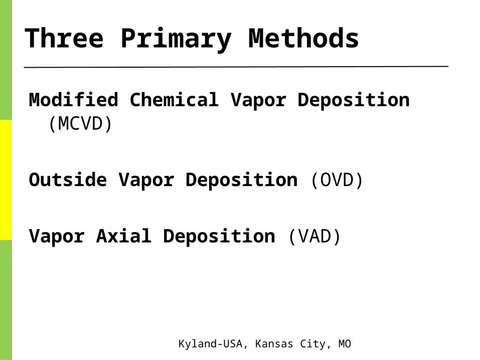
Three Primary Methods
Modified Chemical Vapor Deposition (MCVD)
Outside Vapor Deposition (OVD)
Vapor Axial Deposition (VAD)

Kyland-USA, Kansas City, MO
Modified Chemical Vapor Deposition (MCVD)A hollow, rotating glass
tube is heated with a torch
Chemicals inside the tube precipitate to form soot
Rod is collapsed to crate a preform
Preform is stretched in a drawing tower to form a single fiber up to 10 km long

Kyland-USA, Kansas City, MO
Modified Chemical Vapor Deposition (MCVD)

Kyland-USA, Kansas City, MO
Outside Vapor Deposition (OVD)A mandrel is coated with a porous preform in
a furnace
Then the mandrel is removed and the preform is collapsed in a process called sintering

Kyland-USA, Kansas City, MO
Vapor Axial Deposition (VAD)Preform is fabricated
continuously
When the preform is long enough, it goes directly to the drawing tower

Kyland-USA, Kansas City, MO
Fiber Drawing
The fiber is drawn from the preform and then coated with a protective coating
Kyland-USA, Kansas City, MO
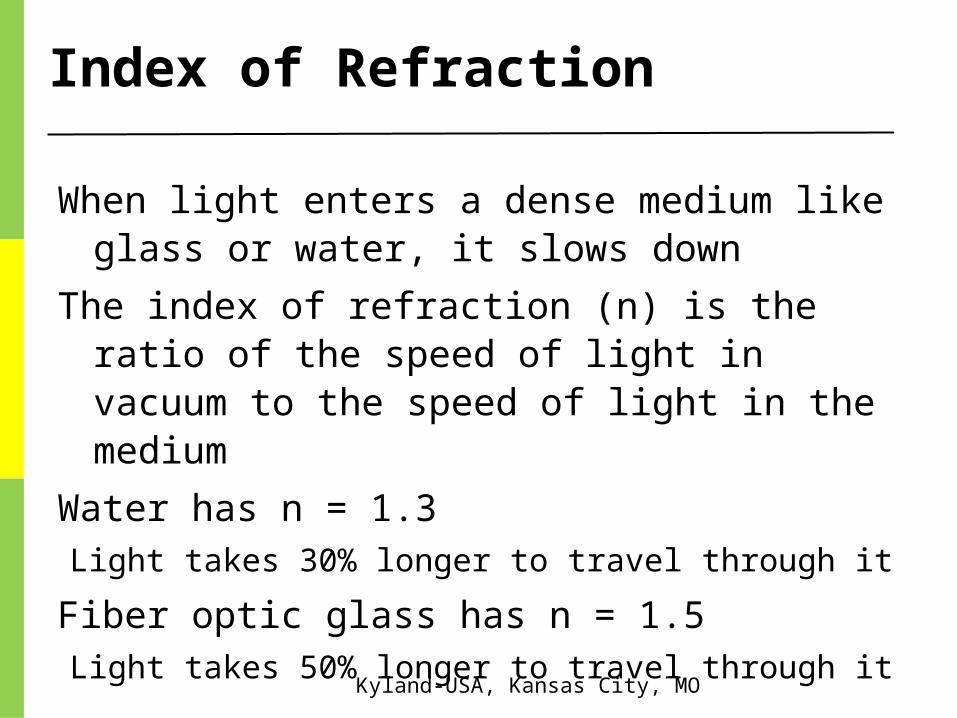
Index of Refraction
When light enters a dense medium like glass or water, it slows down
The index of refraction (n) is the ratio of the speed of light in vacuum to the speed of light in the medium
Water has n = 1.3 Light takes 30% longer to travel through it
Fiber optic glass has n = 1.5Light takes 50% longer to travel through it

Kyland-USA, Kansas City, MO
Fiber Applications

Kyland-USA, Kansas City, MO
Step-index Multi-mode
Large core size, so source power can be efficiently coupled to the fiber
High attenuation (4-6 dB / km)
Low bandwidth (50 MHz-km)
Used in short, low-speed datalinks
Also useful in high-radiation environments, because it can be made with pure silica core

Kyland-USA, Kansas City, MO
Graded-index Multi-mode
Useful for “premises networks” like LANs, security systems, etc.
62.5/125 micron has been most widely usedWorks well with LEDs, but cannot be used for
Gigabit Ethernet
50/125 micron fiber and VSELS are used for faster networks

Kyland-USA, Kansas City, MO
Single-mode Fiber
* Best for high speeds and long distances
• Used by telephone companies and CATV
• Used Outdoors & Between Buildings

Kyland-USA, Kansas City, MO
Fiber Performance

Kyland-USA, Kansas City, MO
AttenuationModern fiber material is very pure, but there is still
some attenuation
The wavelengths used are chosen to avoid absorption bands
850 nm, 1300 nm, and 1550 nm
Plastic fiber uses 660 nm LEDs

Kyland-USA, Kansas City, MO
The 3 Types of Dispersion
Dispersion is the spreading out of a light pulse as it travels through the fiber
Three types:Modal Dispersion
Chromatic Dispersion
Polarization Mode Dispersion (PMD)

Kyland-USA, Kansas City, MO
Modal Dispersion
Modal DispersionSpreading of a pulse because different modes
(paths) through the fiber take different times
Only happens in multimode fiber
Reduced, but not eliminated, with graded-index fiber
Kyland-USA, Kansas City, MO
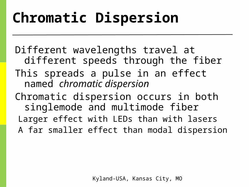
Chromatic Dispersion
Different wavelengths travel at different speeds through the fiber
This spreads a pulse in an effect named chromatic dispersion
Chromatic dispersion occurs in both singlemode and multimode fiber
Larger effect with LEDs than with lasersA far smaller effect than modal dispersion

Kyland-USA, Kansas City, MO
Polarization Mode Dispersion
Light with different polarization can travel at different speeds, if the fiber is not perfectly symmetric at the atomic level
This could come from imperfect circular geometry or stress on the cable, and there is no easy way to correct it
It can affect both single-mode and multi-mode fiber.

Kyland-USA, Kansas City, MO
Modal Distribution
In graded-index fiber, the off-axis modes go a longer distance than the axial mode, but they travel faster, compensating for dispersion
But because the off-axis modes travel further, they suffer more attenuation

Kyland-USA, Kansas City, MO
Equilibrium Modal Distribution
A long fiber that has lost the high-order modes is said to have an equilibrium modal distribution
For testing fibers, devices can be used to condition the modal distribution so measurements will be accurate

Kyland-USA, Kansas City, MO
Mode Stripper
An index-matching substance is put on the outside of the fiber to remove light travelling through the cladding

Kyland-USA, Kansas City, MO
Mode Scrambler
Mode scramblers mix light to excite every possible mode of transmission within the fiber
Used for accurate measurements of attenuation

Kyland-USA, Kansas City, MO
Mode Filter
Wrapping the fiber around a 12.5 mm mandrel
Exceeds the critical angle for total internal reflection for very oblique modes
The high-order modes leak into the cladding and are lost
That creates an equilibrium modal distributionAllows an accurate test with a short test cable

Kyland-USA, Kansas City, MO
Decibel Units

Kyland-USA, Kansas City, MO
AKA – Poor Mans Attenuator
Wrapping the fiber around a 12.5 mm mandrel
Or wrapping fiber in a tight circle such as your hand – cuts down the light (or hot signal) down to acceptable receiver levels – preventing Receiver Saturation / Link Loss.

Kyland-USA, Kansas City, MO
Optical Loss in dB (decibels)
If the data link is perfect, and loses no power
The loss is 0 dB
If the data link loses 50% of the power
The loss is 3 dB, or a change of – 3 dB
If the data link loses 90% of the power
The loss is 10 dB, or a change of – 10 dB
If the data link loses 99% of the power
The loss is 20 dB, or a change of – 20 dB
dB = 10 log (Power Out / Power In)
Data LinkPower In Power Out

Kyland-USA, Kansas City, MO
Absolute Power in dBm
The power of a light is measured in milli-watts
For convenience, we use the dBm units, where
-20 dBm = 0.01 milli-watt
-10 dBm = 0.1 milli-watt
0 dBm = 1 milli-watt
10 dBm = 10 milli-watts
20 dBm = 100 milli-watts

Kyland-USA, Kansas City, MO
Construction Hints
For cable installed in underground conduit:No more than 200m between pull points
Reduce distance by 50m for every 90 degrees of bend

Kyland-USA, Kansas City, MO
Fiber Optic Cable Construction
Leave slack loops

Kyland-USA, Kansas City, MO
DYMEC
Kyland-USA
DYMEC is a registered trademark of Kyland-USA
THANK YOU !