KUKA User Manual -...
68
User Manual Po-Chen Wu Media IC and System Lab Graduate Institute of Electronics Engineering National Taiwan University KUKA KR 16-2 Reference: http://forum.robotsinarchitecture.org/index.php?action=dlattach;topic=20.0;attach=11
Transcript of KUKA User Manual -...
User Manual
Po-Chen Wu
Media IC and System Lab
Graduate Institute of Electronics Engineering
National Taiwan University
KUKA KR 16-2
Reference: http://forum.robotsinarchitecture.org/index.php?action=dlattach;topic=20.0;attach=11

Outline
• Introduction
• How to Edit Codes
• How to Control the Robot Arm
• Others
2
Outline
• Introduction
• How to Edit Codes
• How to Control the Robot Arm
• Others
3

Introduction to KR 16-2
• Payload
– 16 kg
• Number of Axes
– 6 axes
• Control Method
– Manual
– Program
4

Begin to Use
1. Boot the computer
2. Press to continue (windows bug)
3. Wait for minutes
5

Outline
• Introduction
• How to Edit Codes
• How to Control the Robot Arm
• Others
6
Log On (1/6)
• We have to log on to edit codes
– It will be logged out automatically when
turning from manual mode to program mode
– Be sure to log on again
7

Log On (2/6)
8
1
2
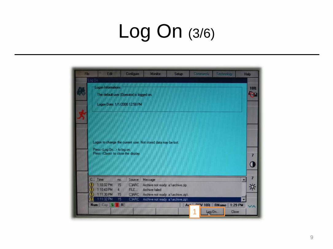
Log On (3/6)
9
1

Log On (4/6)
10
2
1

Log On (5/6)
11
2
1. Type “kuka” (lower case)
(or just press enter)
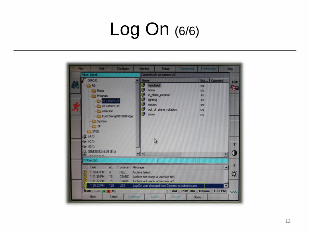
Log On (6/6)
12

Create a New Code File (1/3)
13
1. Highlight this window
2

Create a New Code File (2/3)
14
2
1

Create a New Code File (3/3)
15
2
1. Type the file name
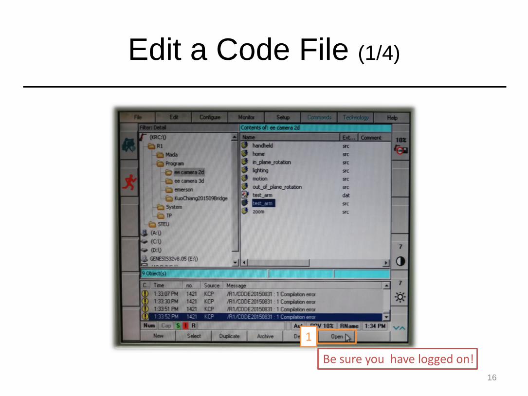
Edit a Code File (1/4)
16
1
Be sure you have logged on!

Edit a Code File (2/4)
17
If you have not logged on yet, you can also log on here

Edit a Code File (3/4)
18
1. Edit your codes
2

Edit a Code File (4/4)
19
1
Tips for Editting
• “Delete” key will delete one whole line
– Use “Backspace” to revise characters
instead.
• Shortcut key
– Ctrl + X (cut)
– Ctrl + C (copy)
– Ctrl + V (paste)
20

Coding Guideline
INI
;Initial Position$VEL.CP = 0.5PTP {POS: X 1000.00, Y 0.00, Z 1000.00, A 90.00, B 0.00, C 90.00, S 6, T 50}
;Motion PartPTP {POS: X 500.00, Y 500.00, Z 500.00, A 90.00, B 0.00, C 90.00, S 6, T 50}PTP {POS: X 1000.00, Y 0.00, Z 1000.00, A 90.00, B 0.00, C 90.00, S 6, T 50} C_PTPT PTP {POS: X 500, Y 500, Z 500, A 90, B 0, C 90, S 6, T 50}LIN {X 1000, Y 0, Z 1000, A 90, B 90, C -180, S 6, T 50}CIRC {X 1000.00, Y 1.00, Z 1000.00, A 90.00, B 0.00, C 90.00}, {X 1000.00, Y -1.00, Z 1000.00, A 90.00, B 0.00, C 90.00 }, CA 180…
21
Part 1. Just type INI"
Part 2. Set the Initial Position
(‘;’ is the comment character; VEL.CP is set for velocity m/s)
Part 3. Motion Part (will be executed continuously)

Example Codes
22
Basic Motion Types
• PTP
– Point-to-point motion
• LIN
– Linear motion
• CIRC
– Circular motion
• HALT
– Halt the moving prosess
23

PTP Motion (1/3)
• The point-to-point motion (PTP) is the quickest way of moving
the tip of the tool (Tool Center Point: TCP) from the current
position to a programmed end position.
• To do this, the controller calculates the necessary angle
differences for each axis.
• Syntax
24
PTP {POS: X 1000.00, Y 0.00, Z 1000.00, A 90.00, B 0.00, C 90.00, S 6, T 50}
PTP {AXIS: A1 0, A2 -90, A3 90, A4 90, A5 0, A6 -180}
or
PTP Motion (2/3)
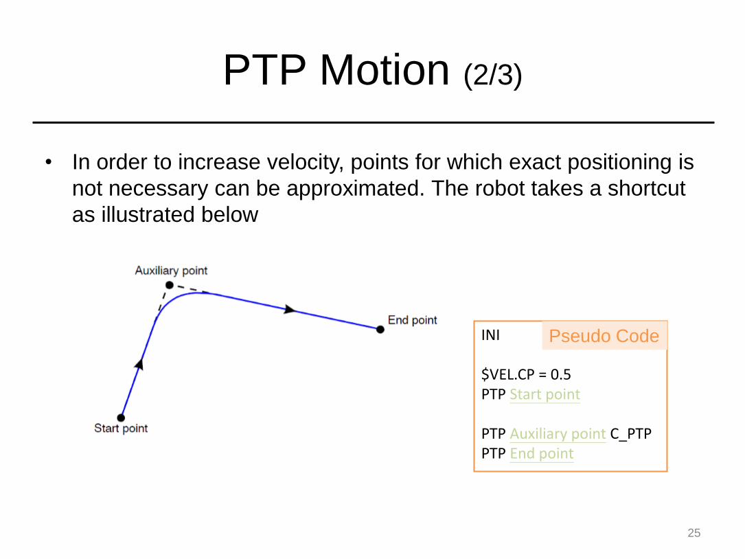
• In order to increase velocity, points for which exact positioning is
not necessary can be approximated. The robot takes a shortcut
as illustrated below
25
INI
$VEL.CP = 0.5PTP Start point
PTP Auxiliary point C_PTPPTP End point
Pseudo Code

PTP Motion (3/3)
26

Linear Motion (1/2)
• In the case of a linear motion, the server calculates a straight
line from the current position (the last point programmed in the
program) to the position specified in the motion command.
• Syntax
27
LIN {X 1000.00, Y 0.00, Z 1000.00, A 90.00, B 0.00, C 90.00}
INI
$VEL.CP = 0.5PTP Start point
LIN End point
Pseudo Code

Linear Motion (2/2)
28
Circular Motion (1/3)
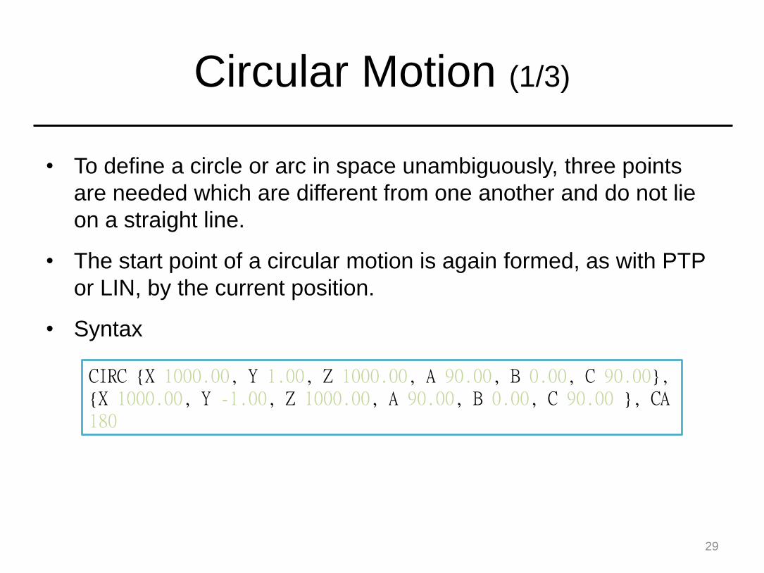
• To define a circle or arc in space unambiguously, three points
are needed which are different from one another and do not lie
on a straight line.
• The start point of a circular motion is again formed, as with PTP
or LIN, by the current position.
• Syntax
29
CIRC {X 1000.00, Y 1.00, Z 1000.00, A 90.00, B 0.00, C 90.00}, {X 1000.00, Y -1.00, Z 1000.00, A 90.00, B 0.00, C 90.00 }, CA 180
Circular Motion (2/3)
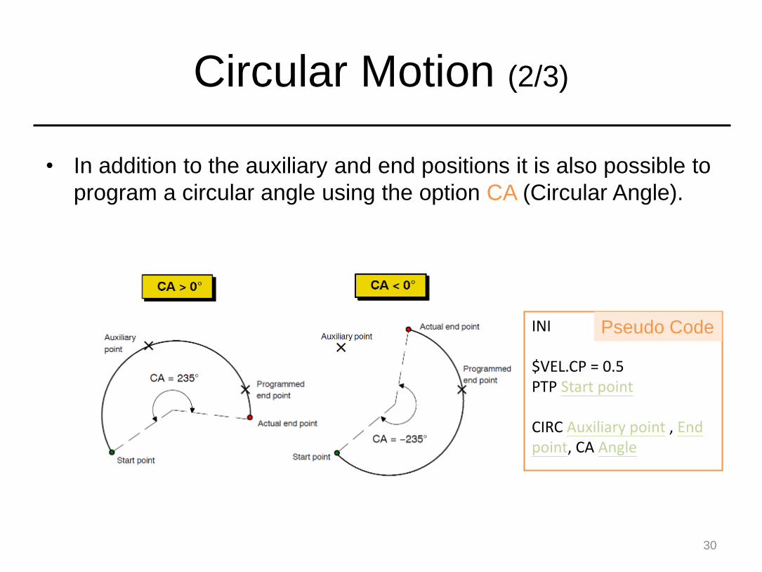
• In addition to the auxiliary and end positions it is also possible to
program a circular angle using the option CA (Circular Angle).
30
INI
$VEL.CP = 0.5PTP Start point
CIRC Auxiliary point , End point, CA Angle
Pseudo Code

Circular Motion (3/3)
31

Halt
• Pause the moving process.
• Resume the motion by pressing .
• Syntax
32
HALT
Outline
• Introduction
• How to Edit Codes
• How to Control the Robot Arm
• Others
33

Two Way to Control
• Program Control
– Execute program codes
– Have to write your codes first
– Just like running script
• Manuel Control
– Control the robot arm manually
– Just like playing game with joystick
34

Program Control (1/9)
35
Power On
Power Off
1

Program Control (2/9)
36
2
1. Choose one file

Program Control (3/9)
37
You cannot run codes if this icon appears in red

Program Control (4/9)
38
1
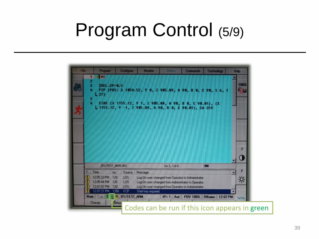
Program Control (5/9)
39
Codes can be run if this icon appears in green
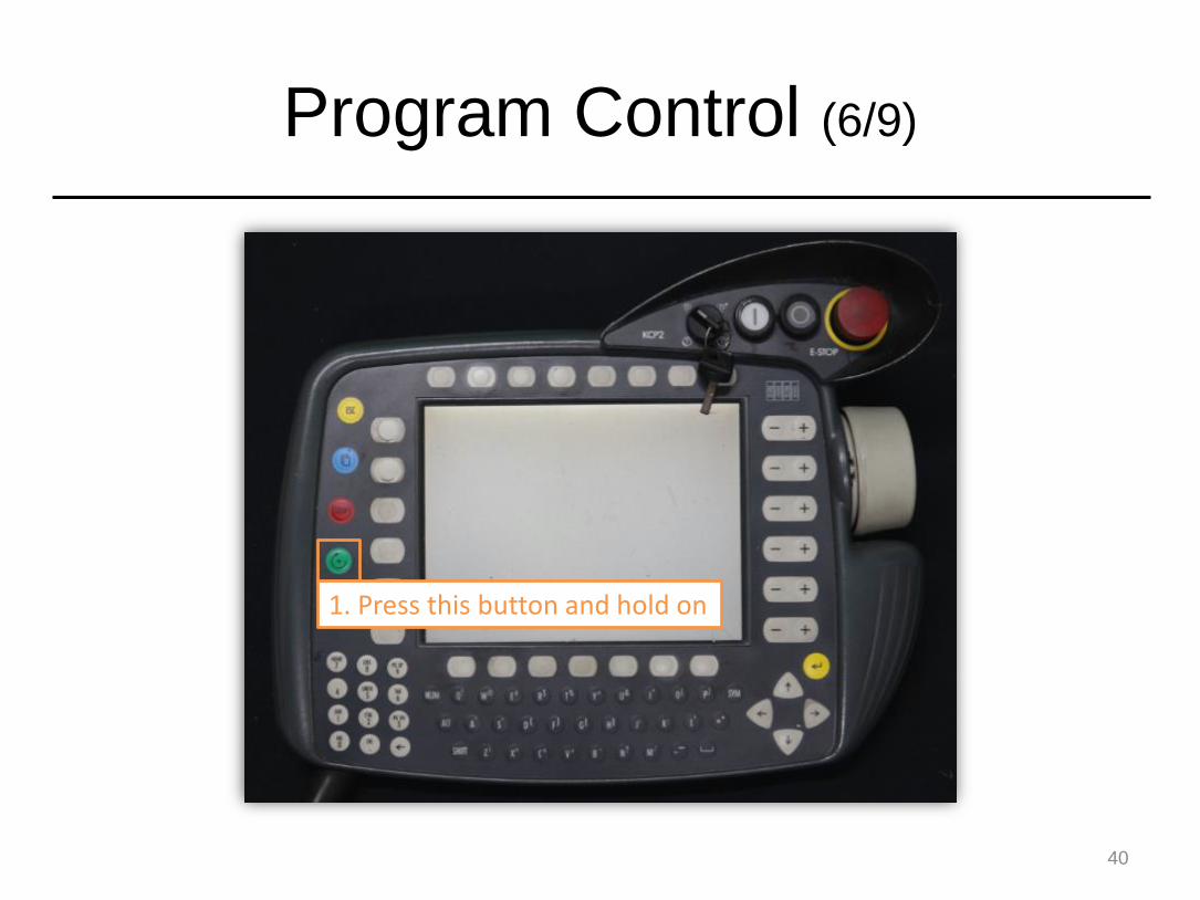
Program Control (6/9)
40
1. Press this button and hold on

Program Control (7/9)
41
This means not finished yet, and you should still press the button for a while

Program Control (8/9)
42
Finished! Pressing the button again can go into the next stage

Program Control (9/9)
43
This part will be executed automatically until reaching the end
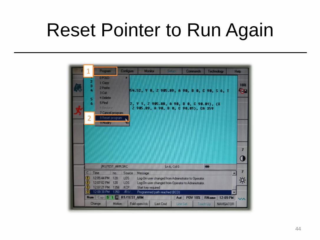
Reset Pointer to Run Again
44
1
2
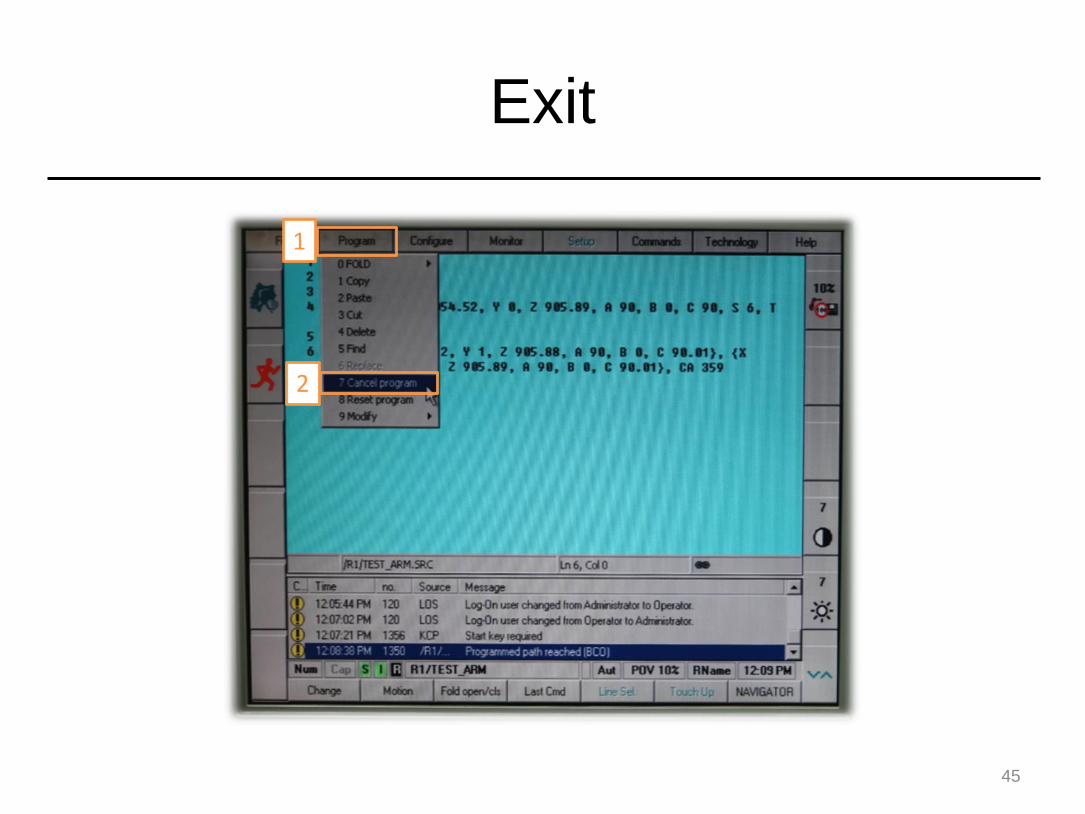
Exit
45
1
2

Revise Codes in Running Mode (1/2)
46
1. Revise codes first
2. Press key ↑ or ↓ to validate the modification

Revise Codes in Running Mode (2/2)
47
The change become effective if this kind of highlight appear again

Change the Moving Speed (1/3)
48
1
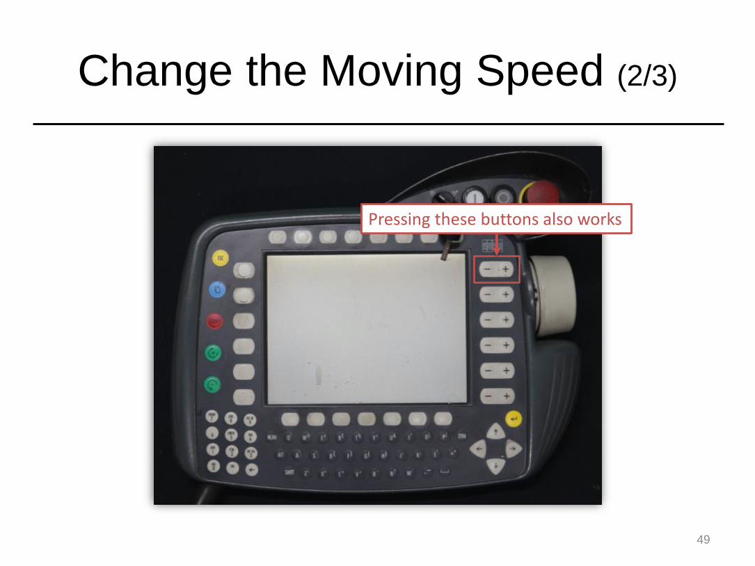
Change the Moving Speed (2/3)
49
Pressing these buttons also works

Change the Moving Speed (3/3)
50
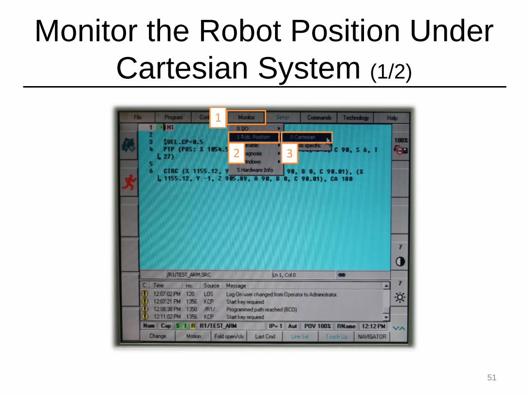
Monitor the Robot Position Under
Cartesian System (1/2)
51
1
2 3
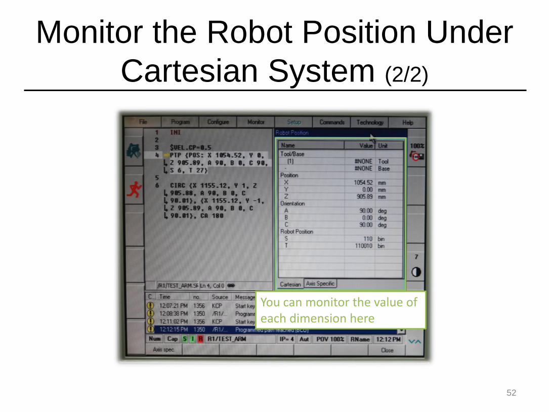
Monitor the Robot Position Under
Cartesian System (2/2)
52
You can monitor the value of each dimension here

Monitor the Robot Position Under
Axis System (1/2)
53
1
23
Pressing here also works

Monitor the Robot Position Under
Axis System (2/2)
54
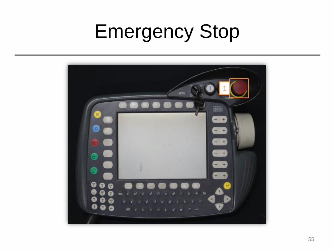
Emergency Stop
55
1
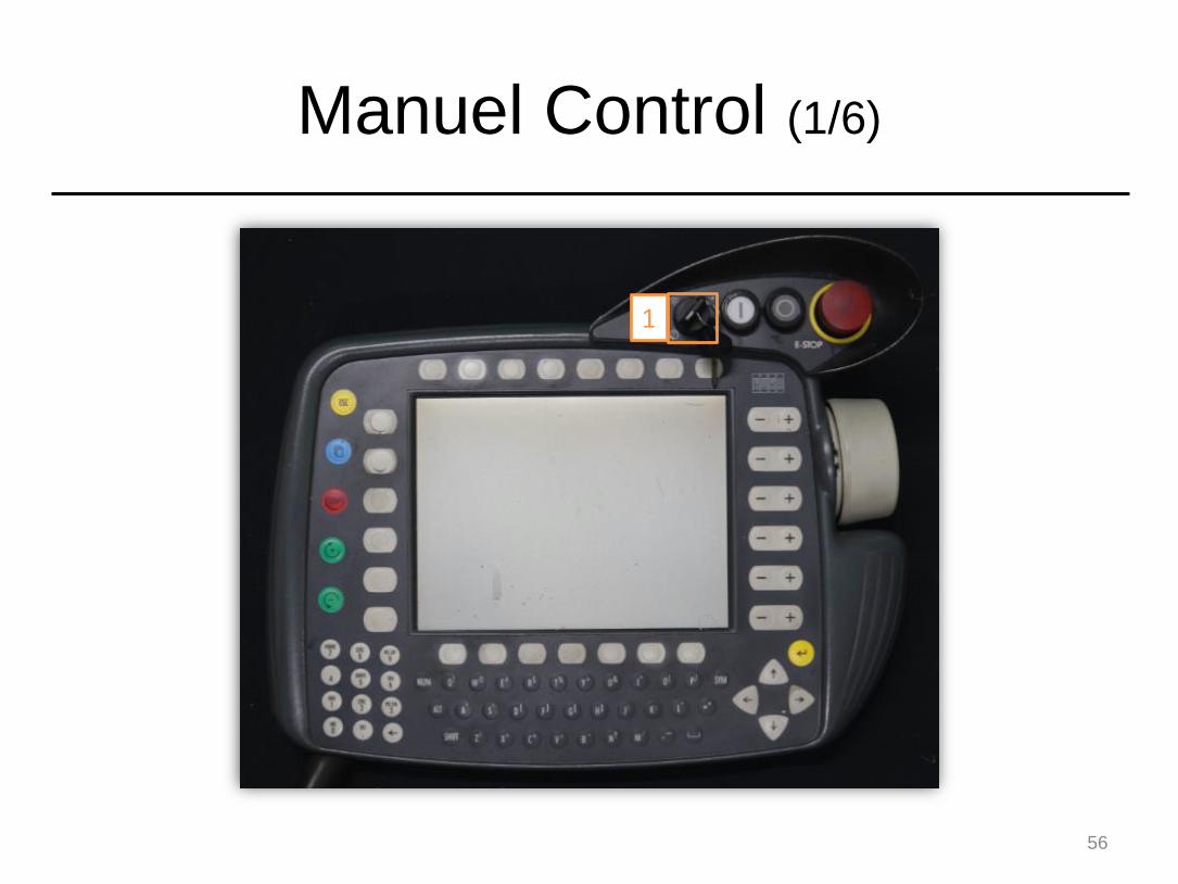
Manuel Control (1/6)
56
1
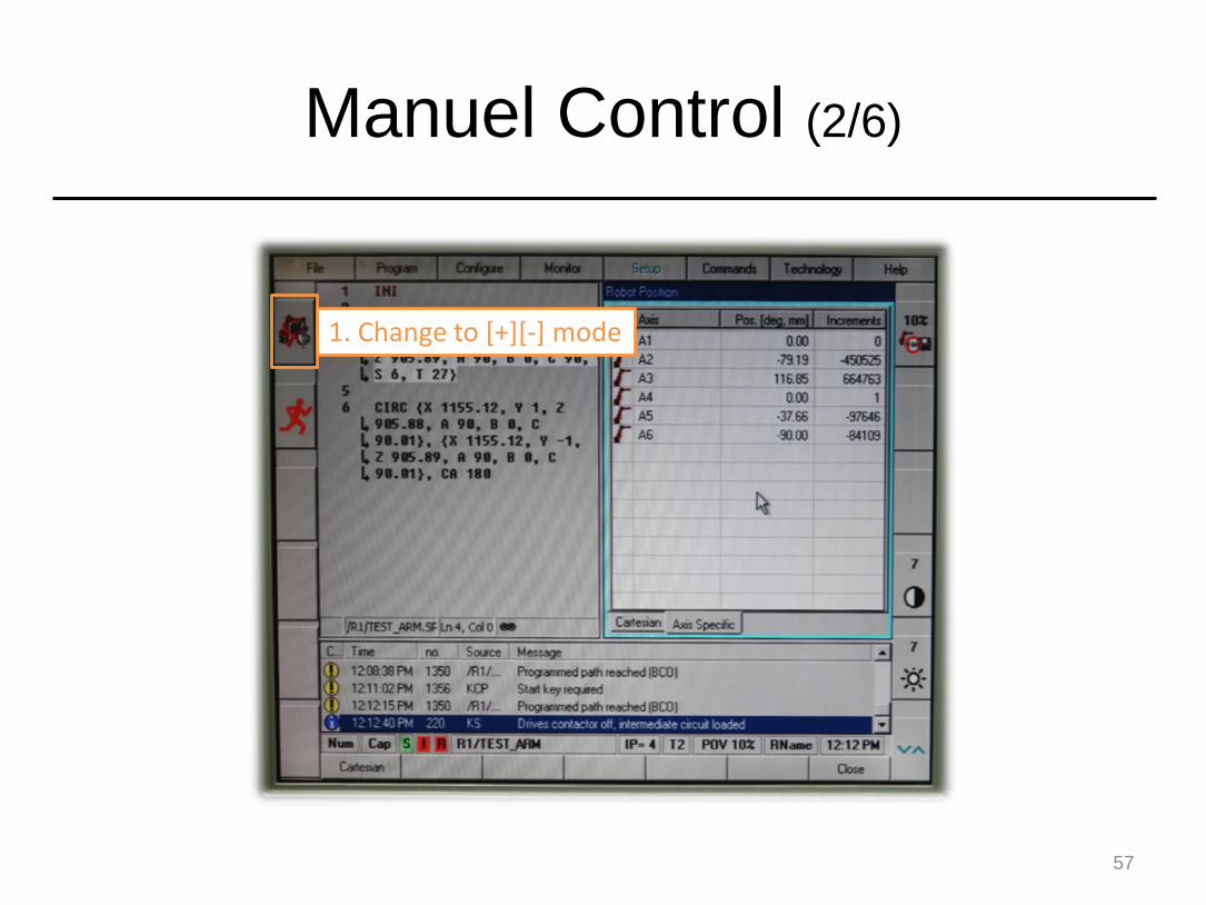
Manuel Control (2/6)
57
1. Change to [+][-] mode

Manuel Control (3/6)
58
Pressing this button also works

Manuel Control (4/6)
59
Axis Mode
Speed (manual)
You cannot control the arm if this icon appears in red

Manuel Control (5/6)
60
1. Press and hold on one of the white keys

Manuel Control (6/6)
61
The arm can be controlled if this icon appears in green
Now you can modify values under axis system
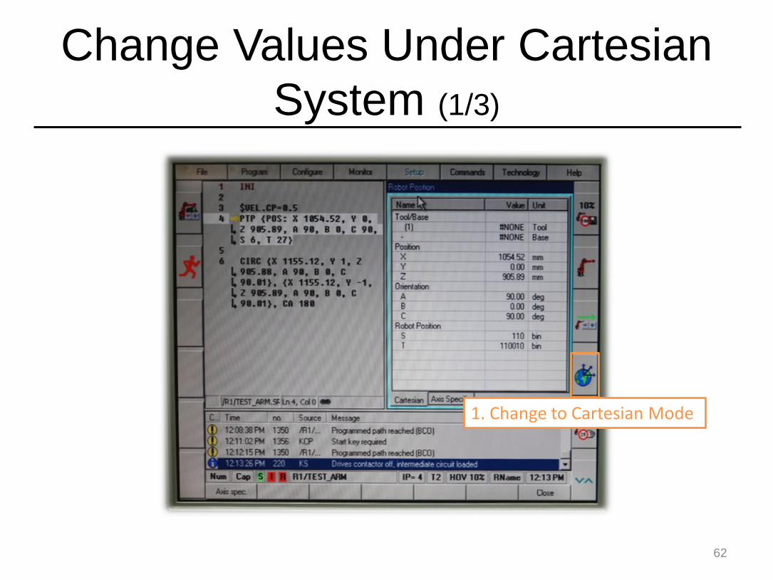
Change Values Under Cartesian
System (1/3)
62
1. Change to Cartesian Mode
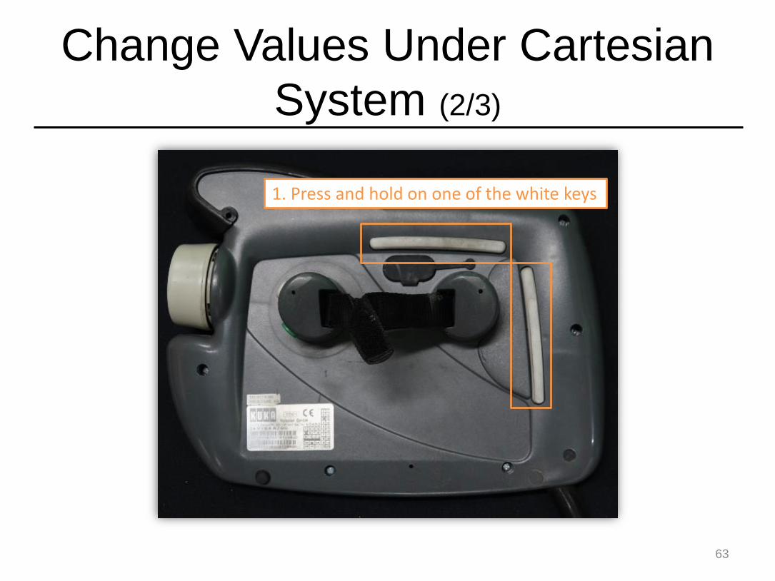
Change Values Under Cartesian
System (2/3)
63
1. Press and hold on one of the white keys

Change Values Under Cartesian
System (3/3)
64
Now you can modify values under Cartesian system
The arm can be controlled if this icon appears in green

Change the Moving Speed in
Manual Mode
65
1. Change the moving speed
Outline
• Introduction
• How to Edit Codes
• How to Control the Robot Arm
• Others
66
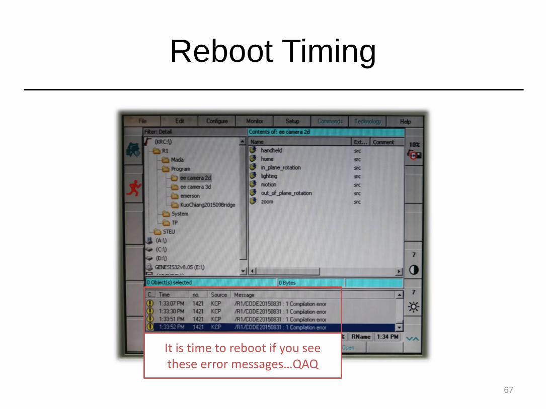
Reboot Timing
67
It is time to reboot if you see these error messages…QAQ
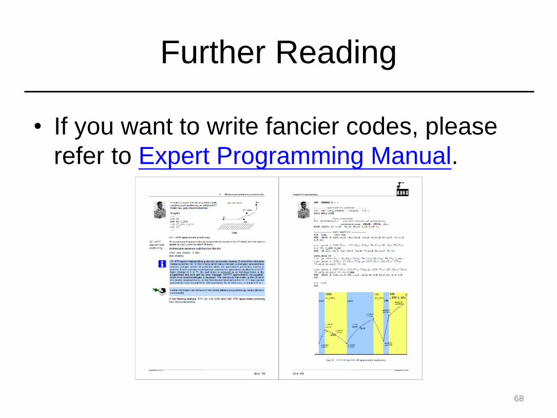
Further Reading
• If you want to write fancier codes, please
refer to Expert Programming Manual.
68