
Kongsberg Simrad EA 500 - AWIepic.awi.de/29971/1/Kon2011d.pdfKongsberg Simrad EA 500 Hydrographic...
206
Kongsberg Simrad EA 500 Hydrographic echo sounder Base version Operator manual
Transcript of Kongsberg Simrad EA 500 - AWIepic.awi.de/29971/1/Kon2011d.pdfKongsberg Simrad EA 500 Hydrographic...

Kongsberg Simrad EA 500Hydrographic echo sounderBase version
Operator manual


Kongsberg Simrad EA 500
Hydrographic echo sounder
Operator manual - Base version
850--043661 / AA000 / 1--11

Note
Kongsberg Simrad AS makes every effort to ensure that the information contained withinthis document is correct. However, our equipment is continuously being improved andupdated, so we cannot assume liability for any errors which may occur.
Warning
The equipment to which this manual applies must only be used for the purpose for whichit was designed. Improper use or maintenance may cause damage to the equipment or injuryto personnel. The user must be familiar with the contents of the appropriate manuals beforeattempting to install, operate or maintain the equipment.
Kongsberg Simrad AS disclaims any responsibility for damage or injury caused byimproper installation, use or maintenance of the equipment.
Copyright
E 2001 Kongsberg Simrad AS
The information contained within this document remains the sole property of KongsbergSimrad AS. No part of this document may be copied or reproduced in any form or by anymeans, and the information contained within is not to be communicated to a third party,without the prior written consent of Kongsberg Simrad AS.
KONGSBERG SIMRAD ASStrandpromenaden 50, P.O.Box 111, N-3191 Horten, Norway
Telephone +47 33 03 40 00 Telefax +47 33 04 44 24www.kongsberg-simrad.com
Support: [email protected]: [email protected]
Technical emergency number, outside office hours: +47 99 20 38 01

Operator manual
I850-043661 / J
Sections
This book is the Operator manual manual for Base version. It describes how to install thevarious units used by the EA 500 system.
The installation of the hull unit is described in a separate manual.
1 System familiarization
2 Operational procedures
3 Command references
4 Maintenance
5 Technical specifications
6 Communication ports
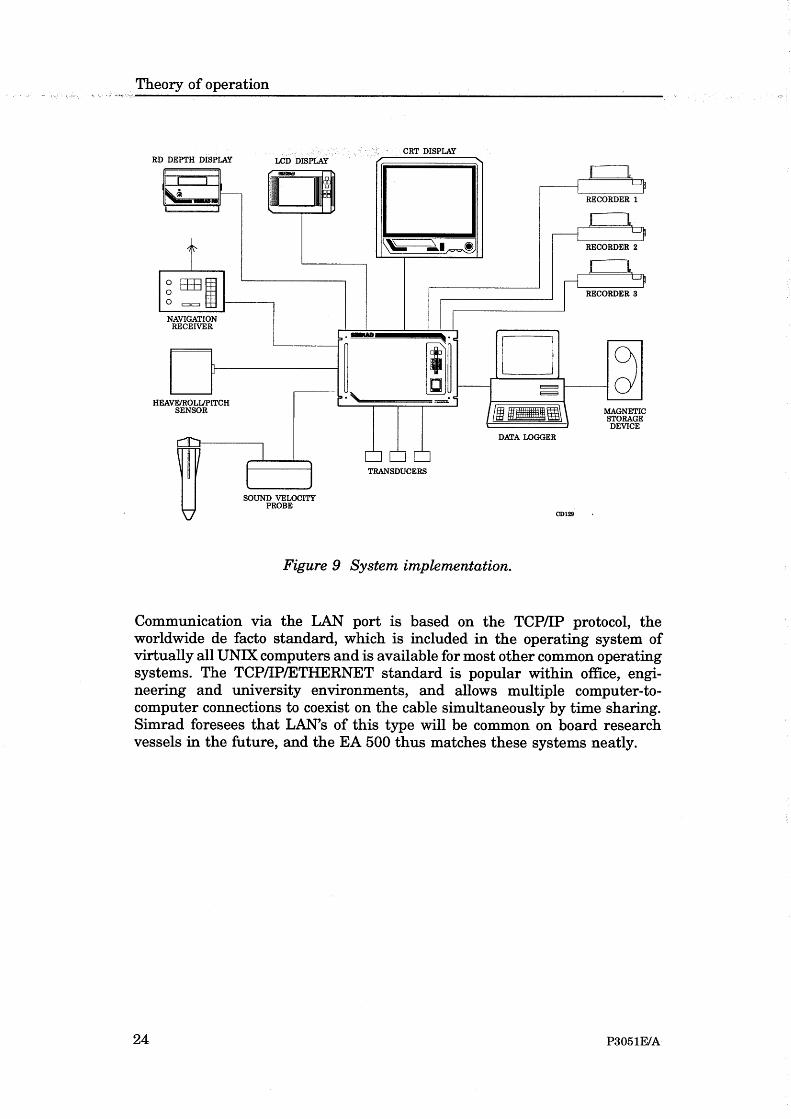
7 Theory of operation
8 Appendices
Kongsberg Simrad EA 500 / Base version
II 850-043661 / J
Remarks
ReferencesFurther information about the EA 500 system may be found in the following manuals:
• EA 500 Maintenance manual
• EA 500 Installation manual
The readerThis operator manual is intended to be used by the system operator. He/she should beexperienced in the operation of echo sounder systems, or should have attended a KongsbergSimrad training course.
NoteThis manual includes sections that may be revised individually. In the event of a revisionto any part of this manual, this “Cover and Contents” section will be replaced.

Operator manual
III850-043661 / J
Document logistics
Rev Date Written Checked Approved
A 01.06.90
B 01.02.91
C 02.02.91
D 31.08.92
E 25.03.93
F 27.05.93
G 08.09.94
H 15.03.96 CL OL EF
I 10.06.97 CL EF EF
J 21.10.01 RBr ESB GM
(The original signatures are recorded in the company’s logistic database.)

Kongsberg Simrad EA 500 / Base version
IV 850-043661 / J
Comments
Rev Comments
A Original edition. Software version 2.40.
B Software version 2.60.
C New rear panel, changes in section 1 only.
D Software version 3.00.
E Software version 4.00. The layout of the manual has been updated to confirm withSimrad standards.
F Corrections and additions throughout the manual, and in the appendices P2265EError Messages and P2571E EA 500 DWS.
G Correction in section ”Introduction”, page 9. Change notice D227.
H Manual modularized, and updated to reflect new software (version 5.20).
I Updated to software version 5.30.
J Manual digitized. System familiarization and Operational procedures converted toQS with new layout, other documents scanned. No changes to the text.
To assist us in making improvements to the product and to this manual, we would welcomecomments and constructive criticism. Please send all such - in writing or by e-mail - to:
Kongsberg Simrad ASDocumentation Department
P.O.Box 111N-3191 Horten
Norway
or e-mail:

Operator manual
V850-043661 / J
Documents
This manual contains the following individual documents:
Cover & Contents 850-043551 Rev.J. . . . . . . . . . . . .
System familiarization 850-130645 Rev.B. . . . . . . . . .
Operational procedures 850-130647 Rev.B. . . . . . . . .
Command references 850-130495 Rev.B (Software version 5.3). . . . . . . . . . .
Maintenance 850-130682 Rev.B. . . . . . . . . . . . . . . . . .
Technical specifications 850-130646 Rev.A. . . . . . . . .
Communication ports 850-130683 Rev.A. . . . . . . . . . .
Theory of operation 850-130659 Rev.A. . . . . . . . . . . .
Appendices:
Status and error messages 859-043870 Rev.F. . . . . . .
EA 500 Sample / ping interval 859-130088 Rev.B. . .
EA 500 Pinger mode 859-043976 Rev.B. . . . . . . . . . .
EA 500 Multi-channel option 859-130096 Rev.B. . . .
EA 500 DWS System 859-130177 Rev.C. . . . . . . . . .
ASCII - Hex conversion table 859-043869 Rev.C. . . .

Kongsberg Simrad EA 500 / Base version
VI 850-043661 / J
Blank page

System familiarization
I850-130645 / B
850-130645 / AA000 / 1-11
EA 500System familiarization
This section of the manual describes the hardware for the echosounder system.

Kongsberg Simrad EA 500 / Base version
II 850-130645 / B
Document revisions
Rev Date Written by Checked by Approved by
A 15.03.96 CL OL EF
B 19.10.01 RBr ESB GM
C
D
(The original signatures are recorded in the company’s logistic database)

System familiarization
III850-130645 / B
Table of contents
1 INTRODUCTION 1. . . . . . . . . . . . . . . . . . . . . . . . . . . . . . . . . . . . . . . . .
2 THE SYSTEM UNITS 2. . . . . . . . . . . . . . . . . . . . . . . . . . . . . . . . . . . . .2.1 Configuration 2. . . . . . . . . . . . . . . . . . . . . . . . . . . . . . . . . . . . . . . . . . . .2.2 Simplified block diagram 3. . . . . . . . . . . . . . . . . . . . . . . . . . . . . . . . . . .2.3 Interconnections 4. . . . . . . . . . . . . . . . . . . . . . . . . . . . . . . . . . . . . . . . . .

Kongsberg Simrad EA 500 / Base version
IV 850-130645 / B
Document history(The information on this page is for internal use)
Rev.A Original issue. Was formerly section 1 of document P2158E.Rev.B Document converted to QS. New images pasted in. No changes to the
text.

System familiarization
1850-130645 / B
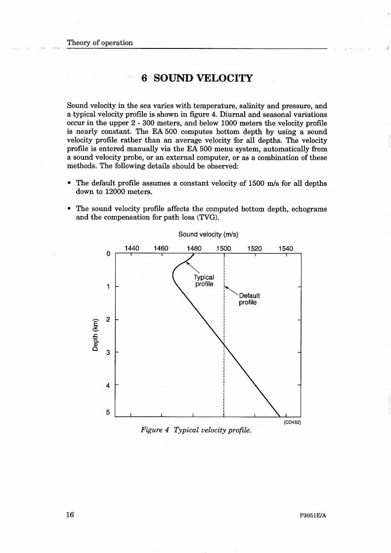
1 INTRODUCTIONSimrad has been in the business of developing special purposeecho sounders since the 1950’s. Accumulated experience,combined with the use of the latest technology and circuit design,has resulted in an echo sounder with greatly improvedperformance and with a number of unique features.
The EA 500 is a modular, triple frequency, high-performancehydrographic echo sounder, with a very accurate reception systemand with independent parallel processing within each of thefrequency channels.
A range of single-beam transducers is available to allow a varietyof frequencies to be used. A dedicated 120 kHz split-beamtransducer is also available for measuring true seabed inclinationin the athwartships direction.
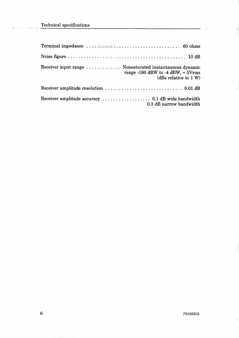
A completely new concept is used in the receiver design, providingan instantaneous dynamic range of 160 dB. At the same time, theabsolute amplitude measurement accuracy is very high, and thiscombined with a low self-noise assures optimum operation undermost conditions. It should be noted that the receivers are neversaturated due to their large instantaneous dynamic range. Hence,very shallow water surveying becomes a trivial exercise.
The bottom detection algorithm is implemented solely in software,and separate calculations are performed for each transducerchannel. The algorithm is designed with emphasis on reliability, sothat erroneous depth detections should not be output. Whereuncertainty exists, the algorithm reports unsuccessful detectionrather than an unreliable depth value. This feature is consideredessential in modern survey work where a post-processor is used forautomatic generation of maps, profiles etc.
The EA 500 system includes a display and colour printers showingechogram and alphanumeric information. The devices areindividually controlled in the sense that echogram range and otherpresentation parameters are set independently for each device.
The sounder is equipped with powerful data interfaces forconnection to external postprocessing and data logging systems.
Kongsberg Simrad EA 500 / Base version
2 850-130645 / B
2 THE SYSTEM UNITS
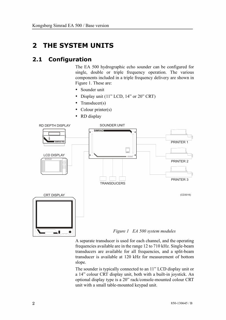
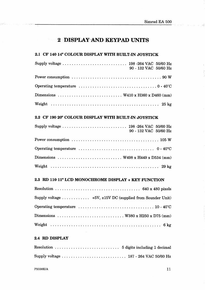
2.1 ConfigurationThe EA 500 hydrographic echo sounder can be configured forsingle, double or triple frequency operation. The variouscomponents included in a triple frequency delivery are shown inFigure 1. These are:• Sounder unit• Display unit (11” LCD, 14” or 20” CRT)• Transducer(s)• Colour printer(s)• RD display
HYDROGRAPHICECHO SOUNDER
SOUNDER UNIT
PRINTER 1
PRINTER 2
PRINTER 3TRANSDUCERS
CRT DISPLAY
LCD DISPLAY
RD DEPTH DISPLAY
SIMRAD RD
SIMRAD
(CD3016)
Figure 1 EA 500 system modules
A separate transducer is used for each channel, and the operatingfrequencies available are in the range 12 to 710 kHz. Single-beamtransducers are available for all frequencies, and a split-beamtransducer is available at 120 kHz for measurement of bottomslope.The sounder is typically connected to an 11” LCD display unit ora 14” colour CRT display unit, both with a built-in joystick. Anoptional display type is a 20” rack/console-mounted colour CRTunit with a small table-mounted keypad unit.
System familiarization
3850-130645 / B
The printers output individually-controllable colour echogramsand alphanumeric data. The paper width is 210 mm, with 720-dotresolution across the paper. Transmitter, receiver, processing andpower electronics are all housed in the sounder unit; a rugged andcompact unit with mechanical dimensions compliant to the 19”rack standard.
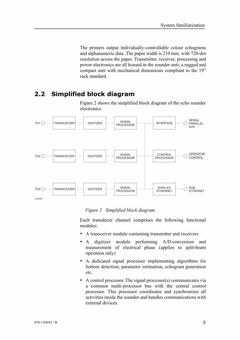
2.2 Simplified block diagramFigure 2 shows the simplified block diagram of the echo sounderelectronics.
TRANSCEIVER
TRANSCEIVER
TD1
TD2
DIGITIZER
DIGITIZER
SIGNALPROCESSOR
SIGNALPROCESSOR
INTERFACE
CONTROLPROCESSOR
SERIALPARALLELAUX
TRANSCEIVERTD3
(CD445)
DIGITIZER SIGNALPROCESSOR
DISPLAY/ETHERNET
RGBETHERNET
Figure 2 Simplified block diagram
Each transducer channel comprises the following functionalmodules:
• A transceiver module containing transmitter and receivers
• A digitizer module performing A/D-conversion andmeasurement of electrical phase (applies to split-beamoperation only)
• A dedicated signal processor implementing algorithms forbottom detection, parameter estimation, echogram generationetc.
• A control processor. The signal processor(s) communicates viaa common multi-processor bus with the central controlprocessor. This processor coordinates and synchronizes allactivities inside the sounder and handles communications withexternal devices.
Kongsberg Simrad EA 500 / Base version
4 850-130645 / B
• A display/Ethernet module controlled by the control processor;the ”Display” part generates standard RGB (Red Green Blue)video signals, and the ”Ethernet” part contains a LAN interfaceof the Ethernet type.
• An interface module including RS232 serial interfaces,Centronics printer interfaces, analogue input signals and outputsignal for external transmit synchronization.
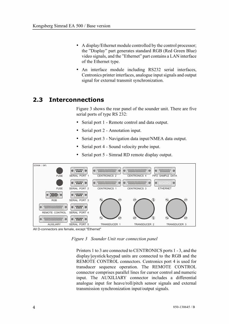
2.3 InterconnectionsFigure 3 shows the rear panel of the sounder unit. There are fiveserial ports of type RS 232:
• Serial port 1 - Remote control and data output.
• Serial port 2 - Annotation input.
• Serial port 3 - Navigation data input/NMEA data output.
• Serial port 4 - Sound velocity probe input.
• Serial port 5 - Simrad RD remote display output.
CENTRONICS 4CENTRONICS 2 FIFO SAMPLE DATA
CENTRONICS 1 CENTRONICS 3 ETHERNET
SERIAL PORT 1
SERIAL PORT 3
SERIAL PORT 4
SERIAL PORT 5
SERIAL PORT 2
TRANSDUCER 1 TRANSDUCER 2 TRANSDUCER 3
RGB
REMOTE CONTROL
AUXILIARY
FUSE
FUSE
(CD038 / GIF)
All D-connectors are female, except "Ethernet"
Figure 3 Sounder Unit rear connection panel
Printers 1 to 3 are connected to CENTRONICS ports 1 - 3, and thedisplay/joystick/keypad units are connected to the RGB and theREMOTE CONTROL connectors. Centronics port 4 is used fortransducer sequence operation. The REMOTE CONTROLconnector comprises parallel lines for cursor control and numericinput. The AUXILIARY connector includes a differentialanalogue input for heave/roll/pitch sensor signals and externaltransmission synchronization input/output signals.

Operational procedures
I850-130647 / B
850-130647 / AA000 / 1-11
EA 500Operational proceduresThis section of the manual describes the man-machineinterface, gives procedures for switching the system on andoff, and includes various operational procedures

Kongsberg Simrad EA 500 / Base version
II 850-130647 / B
Document revisions
Rev Date Written by Checked by Approved by
A 15.03.96 CL OL EF
B 19.10.01 RBr ESB GM
C
D
(The original signatures are recorded in the company’s logistic database)

Operational procedures
III850-130647 / B
Table of contents
1 INTRODUCTION 1. . . . . . . . . . . . . . . . . . . . . . . . . . . . . . . . . . . . . . . . .1.1 Overview 1. . . . . . . . . . . . . . . . . . . . . . . . . . . . . . . . . . . . . . . . . . . . . . . .1.2 The joystick 1. . . . . . . . . . . . . . . . . . . . . . . . . . . . . . . . . . . . . . . . . . . . . .
2 THE DISPLAY AND PRINTER LAYOUT 2. . . . . . . . . . . . . . . . . .2.1 The display layout 2. . . . . . . . . . . . . . . . . . . . . . . . . . . . . . . . . . . . . . . . .2.2 The printer layout 2. . . . . . . . . . . . . . . . . . . . . . . . . . . . . . . . . . . . . . . . .
3 COLOUR SCALE 6. . . . . . . . . . . . . . . . . . . . . . . . . . . . . . . . . . . . . . . . . .
4 HOW TO SWITCH THE ECHO SOUNDER ON AND OFF 7. .
5 HARD RESET 8. . . . . . . . . . . . . . . . . . . . . . . . . . . . . . . . . . . . . . . . . . . . .
6 OPERATIONAL PROCEDURES 9. . . . . . . . . . . . . . . . . . . . . . . . . . .6.1 Introduction 9. . . . . . . . . . . . . . . . . . . . . . . . . . . . . . . . . . . . . . . . . . . . . .6.2 How to start the sounder 9. . . . . . . . . . . . . . . . . . . . . . . . . . . . . . . . . . . .6.3 How to generate a bottom range echogram
on the display and printer echograms 9. . . . . . . . . . . . . . . . . . . . . . . . . .6.4 How to generate scale lines on the display and printer echograms 10. . .6.5 How to generate event markers on the display and printer echograms 106.6 How to generate bottom detection line(s) on the display
and printer echograms 10. . . . . . . . . . . . . . . . . . . . . . . . . . . . . . . . . . . . . .6.7 How to generate annotations on the printer 11. . . . . . . . . . . . . . . . . . . . .6.8 How to generate navigation data on the printer 11. . . . . . . . . . . . . . . . . .6.9 How to generate an athwartships bottom slope
line on the display and printer echograms 11. . . . . . . . . . . . . . . . . . . . . .

Kongsberg Simrad EA 500 / Base version
IV 850-130647 / B
Document history(The information on this page is for internal use)
Rev.A Original issue.Rev.B Document converted to QS, images scanned and pasted in. No changes
to the text.

Operational procedures
1850-130647 / B
1 INTRODUCTION
1.1 OverviewThe display unit normally fitted with the EA 500 echo sounder isa 14” colour display. This unit has a joystick located towards theright side of the front panel, below the display, that is used tocontrol the echo sounder system. Other types of display units mayuse ”Arrow” keys in place of a joystick. Pushing an arrow key willhave the same effect as pressing the joystick in the correspondingdirection.
1.2 The joystickThe joystick enables the operator to move a cursor (a reverse videofield) over the desired choices in the menu. Each press up ( ) ordown ( ) on the joystick will move the cursor one line up or downin the text. A push to the right ( ) will select the particularparameter, or enter the set value, and return the system to thesubmenu. Pushing to the left ( ) will exit the parameter or submenuwithout effecting any changes to the values.
A summary of the commands are:
Up - Moves the cursor upwards on the menu or increases value ofparameter
Down - Moves the cursor downwards on the menu or decreasesvalue of parameter
Right - Selects parameter/enters value, and returns system tosubmenu
Left - Exits parameter/submenu without making changes, andreturns system to previous menu level.

Kongsberg Simrad EA 500 / Base version
2 850-130647 / B
2 THE DISPLAY AND PRINTER LAYOUT
2.1 The display layoutThe display screen is divided into two main sections; the systemmenu is displayed towards the left side, and the graphic field(echogram) is displayed towards the right.
The following information will be added to the echogram if theappropriate settings are made in the menu by the operator:
• Bottom range echogram.
• Scale lines.
• Bottom slope line.
• Bottom detection lines.
• Event marker.
Figure 1 Display echogram example
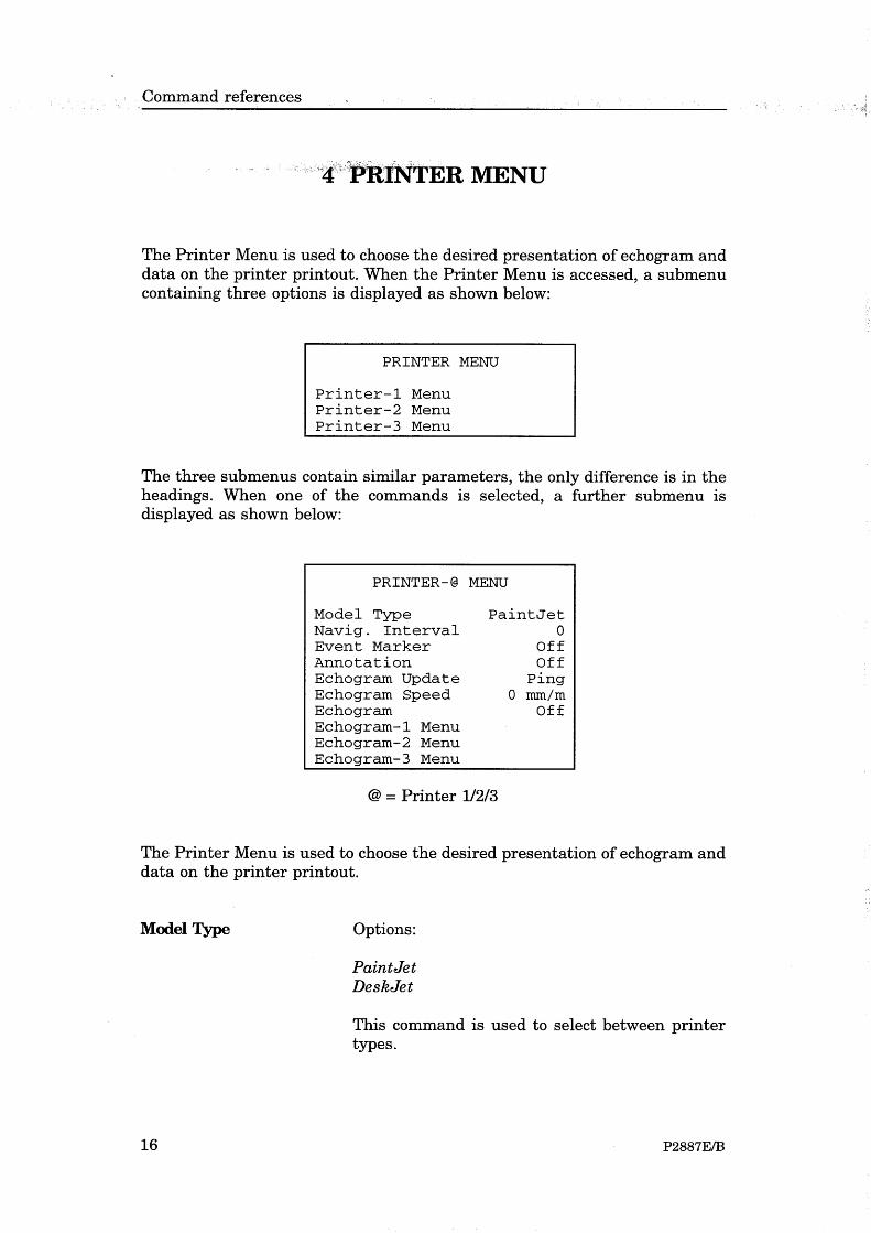
2.2 The printer layoutThe printer is able to generate a combination of echograms, linesand text. Most elements are controlled by parameters located in thePrinter Menu.
The printer echogram may contain all the information of thedisplay echogram, as well as the additional elements:
Operational procedures
3850-130647 / B
• Nautical mile marker
• Annotation
• Date and time
• Navigation text
The control of one printer device will have no influence on theother EA 500 output devices. The colour printer is specified for amaximum paper speed of 5 lines/sec. It has a graphic resolution of720 dots, using 12 different colours ranging from blue to red. Blackis used mainly on text and separation lines.
The printer may have up to three independent echograms. Theechogram number is associated with the transceiver number, henceit will be impossible to print two separate echograms from onetransceiver on the same printer.
A typical layout of a printout is shown in figure 2, while figure 3shows an echogram with along. slope fixes.

Kongsberg Simrad EA 500 / Base version
4 850-130647 / B
Figure 2 Printer echogram
1 - Annotation text
2 - Annotation date and time
3 - Event marker and number
4 - Navigation data
5 - Bottom range6 - Scale lines7 - Range8 - Bottom detection range9 - Bottom slope

Operational procedures
5850-130647 / B
Figure 3 Printout with four along-slope fixes

Kongsberg Simrad EA 500 / Base version
6 850-130647 / B
3 COLOUR SCALEThe colour scale is proportional to the strength of the signals, andthe echo strength is divided into twelve colour categories. Thescale is logarithmic with a 3 dB step between each colour, givingthe colour scale a range of 36 dB from the weakest to the strongestecho signal.
Display colour Signal strength range
Black/white From weak signal to --44 dB
Blue 44 to --41 dB
--41 to --38 dB
--38 to 35 dB
--35 to --32 dB
--32 to --29 dB
--29 to --26 dB
--26 to --23 dB
--20 to --17 dB
--17 to --14 dB
--14 to --11 dB
Red From --11 dB to very strong signal
The colour scale is displayed in the echogram. Note that the aboverelationship between colours and dB values is only valid when theColour Gain parameter is set to 0 dB.
Operational procedures
7850-130647 / B
4 HOW TO SWITCH THE ECHO SOUNDERON AND OFF
1 Switch on the mains power to the Sounder Unit. The On/Offswitch is located on the front side of the unit.
2 Switch on the mains power to the Display Unit. The On/Offswitch is located on the front side of the unit.
3 Switch on the mains power to the printer(s).
4 To switch the echo sounder off, reverse the above procedure.

Kongsberg Simrad EA 500 / Base version
8 850-130647 / B
5 HARD RESETHard reset is achieved by pressing the joystick to the left whenswitching on the power. The contents of the RAM will then bereset, and the sounder will come up with the default settings. Hardreset is also achieved by pressing the switch behind the holemarked HR on the Transceiver Unit front when switching on thepower.

Operational procedures
9850-130647 / B
6 OPERATIONAL PROCEDURES
6.1 IntroductionThe echogram movement across the screen and on the printer isdetermined by the setting of the Echogram Speed parameter(Display Menu and Printer Menu) and the Ping Interval (OperationMenu). The echogram colour presentation is mainly influenced byColour Gain and the selected TVG (DISPLAY/Echogram Menuand PRINTER/Echogram Menu). If the Bottom Range Pres.command is enabled, 20% of the main echogram is overwritten bya bottom-referenced echogram. Note that, in the followingprocedures, # denotes transceiver number and @ printer number.
6.2 How to start the sounderThe following procedure is the minimum required to instruct theecho sounder to start pinging, track the bottom and generate anechogram. In this example it is assumed that only transceiverchannel 1 is used.
1 Select the Transceiver menu.
2 Select the Transceiver-1 menu and check that Mode is set toActive.
3 Select the Display menu and check that Echogram is set to1.
4 Select the Bottom detection-1 menu and set Maximum depthto a value at least as deep as the maximum depth to beexpected.
5 Select the Operator menu, and set Ping mode to Normal.
After a short delay, the sounder will start to ping and an echogramwill begin scrolling from right to left on the display.
6.3 How to generate a bottom range echogramon the display and printer echograms
1 Select the DISPLAY/Echogram-# Menu (or thePRINTER/Echogram-# Menu).
2 Set the Bot. Range Pres. command to Upper, Bottom orLower, depending on where you want the Bottom Range tobe positioned.
3 Set Bottom Range to the desired range of the bottomechogram.

Kongsberg Simrad EA 500 / Base version
10 850-130647 / B
4 Set Bottom Range Start to the desired upper start depth of thebottom echogram.
The bottom range echogram is independent of the main echogram.It will overwrite 20% of the main echogram. The bottom rangeechogram is separated from the main echogram with a solidboundary line. The bottom range echogram is blanked out if nobottom detection has been done.
If Sub.Bottom Gain is set above 0.0 dB/m, the bottom rangepresentation will feature an excess gain below the detected bottom.
6.4 How to generate scale lines on the displayand printer echograms
1 Select the DISPLAY/Echogram-# Menu (or thePRINTER-@/Echogram-# Menu).
2 Select Scale Lines and enter the number of equidistant linesyou want across the echogram.
6.5 How to generate event markers on thedisplay and printer echograms
1 Select the Display Menu (or the Printer Menu).
2 Set Event Marker to On.
The event input may be caused by an external push button oractivated by Event Counter in the Annotation Menu. The event willresult in a red vertical line on the screen and on the printout. Theechogram printout will also include the current event number andnavigation data.
6.6 How to generate bottom detection line(s) onthe display and printer echograms
The bottom detection line may be introduced for easy marking ofthe bottom. Each channel has the possibility of displaying thebottom detection line of other channels.
1 Select the DISPLAY/Echogram-# Menu (or thePRINTER-@/Echogram-# Menu).
2 Set Bot. Det. Line to any of these combinations: 1, 2, 1&2,3, 1&3, 2&3, 1&2&3.
3 To select which type of sub-bottom presentation you want,set Presentation to Normal, Wh. Line or Contour.

Operational procedures
11850-130647 / B
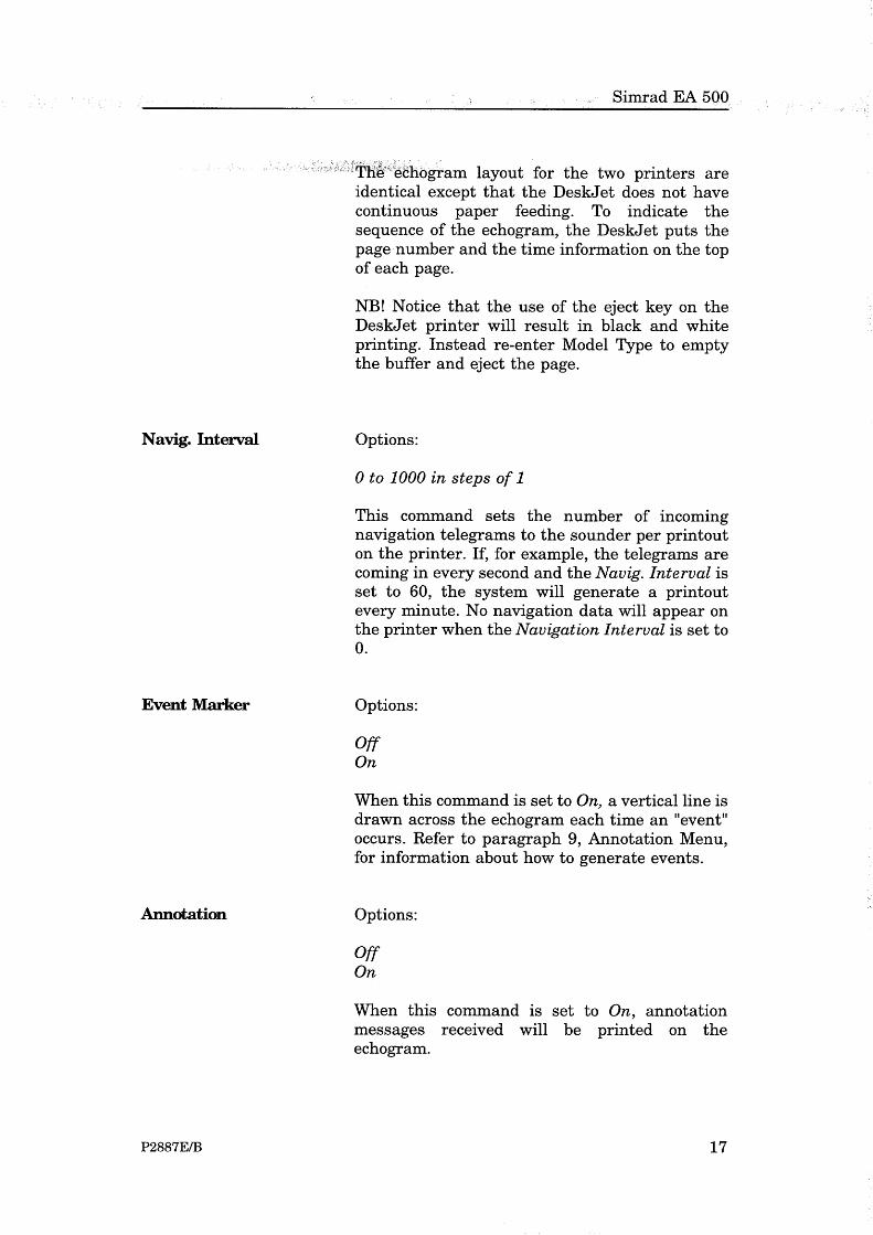
6.7 How to generate annotations on the printer1 Select the PRINTER-@/Echogram-# Menu.
2 Set Annotation to On.
3 Annotation messages received will then be printed on theechogram.
6.8 How to generate navigation data on theprinter
1 Select the PRINTER-@/Echogram-# Menu.
2 Set Navigation Interval to the desired value.
3 The Navigation Interval command sets how often theincoming navigation telegrams are to be printed on theechogram.
If, for example, the navigation telegrams are coming in everysecond and the Navigation Interval is set to 60, the navigation datawill be printed every minute.
No navigation data will appear on the printer when NavigationInterval i set to 0.
6.9 How to generate an athwartships bottomslope line on the display and printerechograms
The athwartships bottom slope line can only be generated if asplit-beam transducer is used.
To see the bottom slope line on the display, select the BottomDetection Menu.
To get a continuous plot of the slope angle on the echogram, selectthe DISPLAY/Echogram-# Menu (or thePRINTER-@/Echogram-# Menu) and set Bot. Slope Line to On.
The bottom slope information will over-print 20% of theechogram. The athwartships slope line (green) is positive when thebottom is shallower on the starboard side. The slope angle valueis plotted as dots in a ±60° scale, with positive values above andnegative values below the 0° line.

Kongsberg Simrad EA 500 / Base version
12 850-130647 / B
Blank page


Maintenance
I850-130682 / B
850-130682 / AA000 / 1-11
EA 500Maintenance
This section of the manual describes the maintenance to beperformed by the system operator.

Kongsberg Simrad EA 500 / Base version
II 850-130682 / B
Document revisions
Rev Date Written by Checked by Approved by
A 15.03.96 CL OL EF
B 21.10.01 RBr ESB GM
C
D
(The original signatures are recorded in the company’s logistic database)

Maintenance
III850-130682 / B
Table of contents
1 INTRODUCTION 1. . . . . . . . . . . . . . . . . . . . . . . . . . . . . . . . . . . . . . . . .
2 PREVENTIVE MAINTENANCE ACTIONS 1. . . . . . . . . . . . . . . . .

Kongsberg Simrad EA 500 / Base version
IV 850-130682 / B
Document history(The information on this page is for internal use)
Rev.A First edition as a combined module for EA 500 and EK 500. Was section 5of P2158E and P2170E.
Rev.B Document transferred to QS, now only valid for EA 500. No changes tothe text.

Maintenance
1850-130682 / B
1 INTRODUCTIONThis chapter describes the preventive maintenance to be performedby the system operator. For details about corrective maintenance,refer to the EA/EK/ES 500 Service Manual. For information abouterror messages, refer to appendix ”Status and error Messages”.
2 PREVENTIVE MAINTENANCE ACTIONSThe preventive maintenance is very limited. When required, cleanthe surfaces of the equipment with a soft, lint-free cloth and a milddetergent. Keep the fan filter of the sounder unit free from dust andmoisture.
For information about preventive maintenance on the printer, referto the printer instruction manual.

Kongsberg Simrad EA 500 / Base version
2 850-130682 / B
Blank page


Simrad EA 500 / EK 500
P2265E/F 1
STATUS AND ERROR MESSAGESP2265E / 859-043870 / 4AA005
This section of the manual details the status and error messages that may bedisplayed by the echo sounder from time to time. All the possible messagesare listed, and an explanation is given for each.

Status and error messages
2 P2265E/F
Document revisions
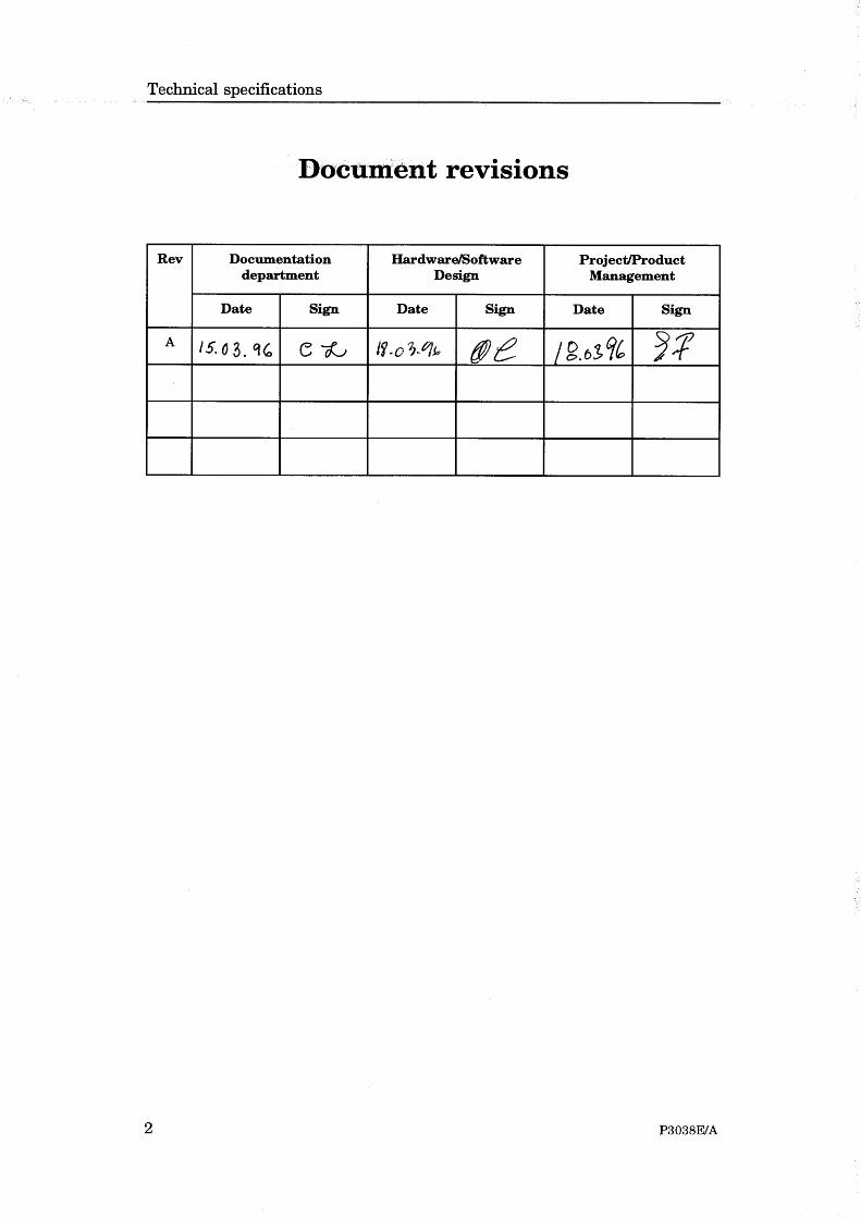
Rev Documentationdepartment
Hardware/SoftwareDesign
Project/ProductManagement
Date Sign Date Sign Date Sign
E 15.03.96 CL 18.03.96 OL 18.03.96 EF
F 22.05.97 CL 22.05.97 HS 22.05.97 RLN

Simrad EA 500 / EK 500
P2265E/F 3
List of contents
1 INTRODUCTION . . . . . . . . . . . . . . . . . . . . . . . . . . . . . . . . . . . . . . . . . . . 5
2 GENERAL MESSAGES . . . . . . . . . . . . . . . . . . . . . . . . . . . . . . . . . . . . . . 5
3 SIGNAL PROCESSOR (SP) ERROR MESSAGES . . . . . . . . . . . . . . . . . . 73.1 INTRODUCTION . . . . . . . . . . . . . . . . . . . . . . . . . . . . . . . . . . . . . . . 73.2 LIST OF SIGNAL PROCESSOR ERROR MESSAGES . . . . . . . . . . 8

Status and error messages
4 P2265E/F
Document history(The remainder of the information on this page is for Simrad internal use).
Revisions:
Rev. A 01.02.91 Original edition.Rev. B 25.06.92 Minor changes to text.Rev. C 31.08.92 Document updated, minor changes to text.Rev. D 16.06.93 Document re-formatted to bring it up to Simrad
standards.Rev. E Document re-formatted to bring it up to new Simrad
standards. This document now applies for both EA 500and EK 500 echo sounders.
Rev. F New error message included (Serial receive overload).

Simrad EA 500 / EK 500
P2265E/F 5
1 INTRODUCTION
The 500-series echo sounders may issue alarms, errors, warnings and othermessages to the display and external devices (via serial port or Ethernet).Note that the # sign indicates the number of the transceiver unit affected(1/2/3). No number is issued for echo sounders with only one transceiver.
Note that the lists include messages for all the echo sounders in the 500series.
2 GENERAL MESSAGES
All messages starting with "SP-#" concern signal processor no. # (described inchapter 3).
Message Explanation
Bottom lost alarm # Bottom tracking lost for transceiver-#
Display not ready Display overload (may occur if system unable to update displaywith the current ping rate)
External trigger error Expected trigger pulse not received
Illegal remote parameter Parameter value of received remote command out of range ornot recognized
Internal error # *
Internal error 7 Spurious interrupt (caused by badly formed trigger pulses etc.)
LAN interrupt level fault *
LAN invalid ind. address The EA 500 local Ethernet address must be an individualaddress, i.e. least significant bit of first byte of address must bezero
LAN invalid multic. adr. Invalid EA 500 multicast address
LAN multicast table full *
LAN no command blocks May appear while CPU is heavily loaded. Regular appearanceof this message indicates a LAN interface terminator orhardware problem
LAN no transmit blocks See above
LAN receive overload Too much data received from LAN (Local Area Network), datais lost
LAN socket table full *
LAN too high priority *
LAN too long message *

Status and error messages
Message Explanation
6 P2265E/F
LAN UDP port busy *
LAN 82586 init error Unable to initialize 82586 chip. Possible hardware fault.
Maximum depth alarm # Bottom of transceiver-# has been detected deeper than themaximum depth alarm setting
Minimum depth alarm # Bottom of transceiver-# has been detected shallower than theminimum depth alarm setting
Navigation telegram error Invalid navigation telegram received
Ping interval warning Ping interval time exceeded
Printer-1 not ready Printer-1 not connected, offline or not ready to print yet
Printer-2 not ready Printer-2 not connected, offline or not ready to print yet
Printer-3 not ready Printer-3 not connected, offline or not ready to print yet
Rem. annotation received Remote annotation has been received successfully
Remote command ignored Remote control received while remote control disabled
Remote parameter entered Remote parameter received, decoded and entered successfully
Remote request executed Remote request has been executed successfully
Serial Com. load warning Too much data is directed to serial port, data may soon be lost
Serial Com. overload Too much data is directed to serial port, data is lost
Serial line 1 error Serial port 1 failure
Serial line 1B error RD display serial port failure
Serial line 2 error Serial port 2 failure
Serial line 3 error Serial port 3 error
Serial line 4 error Serial port 4 error
Serial receive overload Unable to receive more data on serial port. Data is lost
Unknown error *
Unknown remote command Invalid remote command path/parameter received
Unknown transceiver type Transceiver hardware switch not recognized
Display processor error Display/graphic processor (80786) malfunction
Disk error 0
File not found
Replay end of file
Replay data not found
Replay bad data
File create error
File open error
File write error
File close error

Simrad EA 500 / EK 500
Message Explanation
P2265E/F 7
Disk full
External critical alarm External critical alarm received
External alarm External alarm received
Table 1
* = Internal software problem encountered. If this error code is displayed, theincident should be reported to Simrad.

Status and error messages
8 P2265E/F
3 SIGNAL PROCESSOR (SP) ERROR MESSAGES
3.1 INTRODUCTION
The signal processor will read the control parameters sent by the controlprocessor before initiating a new ping. The program will then test eachparameter against its legal values. If the parameter is found to be illegal, orthe value does not agree with the other settings, an error message code issent to the control processor which will issue the error message.
At power-up the signal processors will never start real pinging until all theparameters are granted. However, in order to receive new information fromthe control processor, it will simulate pinging until no errors occur.
If the error message "SP-# not responding error" is shown on the display, thesignal processor has not answered within a time-out period. This error isprobably caused by one of the following hardware errors:
1 No signal processor PCB present.
2 A new PROM set is not properly inserted in the signal processor (checkcarefully).
3 The IC used for signalling is defective (U42 = 8255). This may bechecked by inserting a new 8255.
4 The FIFO system on the digital interface pcb is not working properly.(If the sounder uses multiple frequencies, try exchanging the digitalinterface boards).
5 The signal processor is defective (replace the board, if possible).
Simrad EA 500 / EK 500
P2265E/F 9
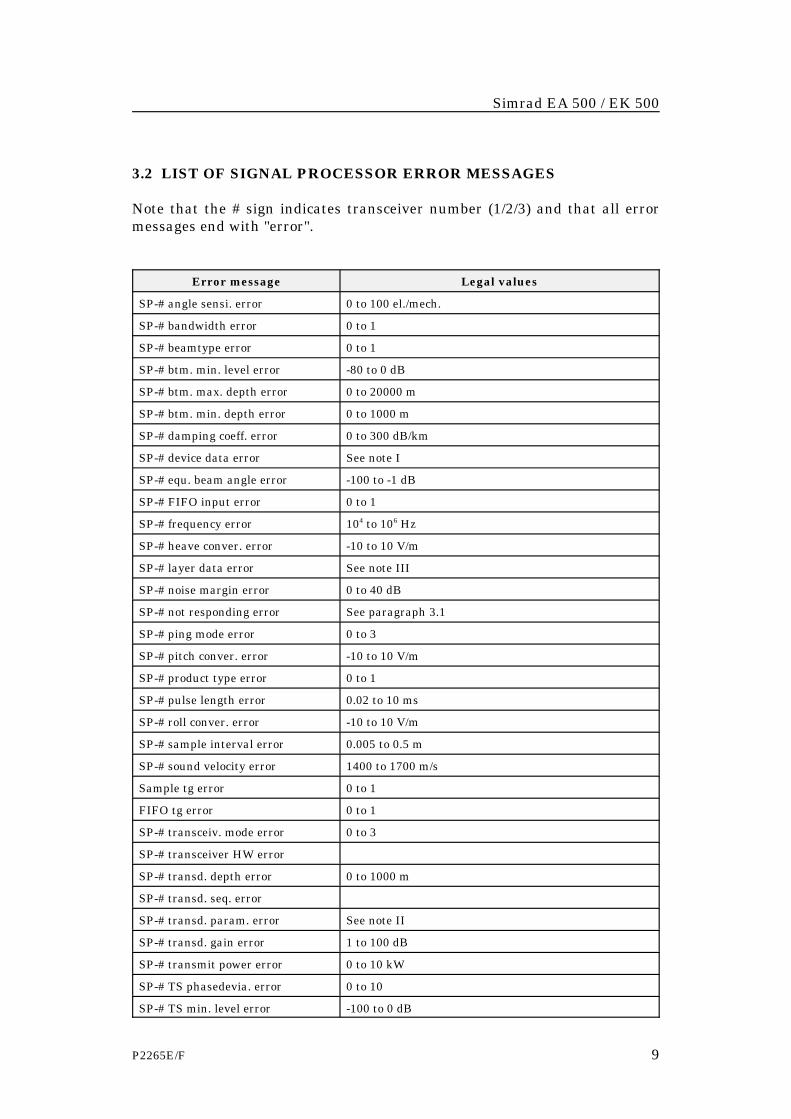
3.2 LIST OF SIGNAL PROCESSOR ERROR MESSAGES
Note that the # sign indicates transceiver number (1/2/3) and that all errormessages end with "error".
Error message Legal values
SP-# angle sensi. error 0 to 100 el./mech.
SP-# bandwidth error 0 to 1
SP-# beamtype error 0 to 1
SP-# btm. min. level error -80 to 0 dB
SP-# btm. max. depth error 0 to 20000 m
SP-# btm. min. depth error 0 to 1000 m
SP-# damping coeff. error 0 to 300 dB/km
SP-# device data error See note I
SP-# equ. beam angle error -100 to -1 dB
SP-# FIFO input error 0 to 1
SP-# frequency error 104 to 106 Hz
SP-# heave conver. error -10 to 10 V/m
SP-# layer data error See note III
SP-# noise margin error 0 to 40 dB
SP-# not responding error See paragraph 3.1
SP-# ping mode error 0 to 3
SP-# pitch conver. error -10 to 10 V/m
SP-# product type error 0 to 1
SP-# pulse length error 0.02 to 10 ms
SP-# roll conver. error -10 to 10 V/m
SP-# sample interval error 0.005 to 0.5 m
SP-# sound velocity error 1400 to 1700 m/s
Sample tg error 0 to 1
FIFO tg error 0 to 1
SP-# transceiv. mode error 0 to 3
SP-# transceiver HW error
SP-# transd. depth error 0 to 1000 m
SP-# transd. seq. error
SP-# transd. param. error See note II
SP-# transd. gain error 1 to 100 dB
SP-# transmit power error 0 to 10 kW
SP-# TS phasedevia. error 0 to 10
SP-# TS min. level error -100 to 0 dB

Status and error messages
Error message Legal values
10 P2265E/F
SP-# TS min. length error 0 to 10
SP-# TS max. length error 0 to 10
SP-# TS max. comp. error 0 to 6 dB
Table 2
Note I
SP-# device data error
The appropriate error message in Table 2 will be displayed if one or more ofthe following parameters are outside legal limits:
Parameter Legal values
Bottom echogram dots 0 to 200.
Bottom range 0 to 100 m.
Bottom range start -100 to 100 m.
Echogram dots 0 to 1000.
Range 0 to 10000 m.
Range start 0 to 10000 m.
Sub-bottom gain 0 to 5 dB/m.
TVG 0 to 2.
Table 3
Simrad EA 500 / EK 500
P2265E/F 11
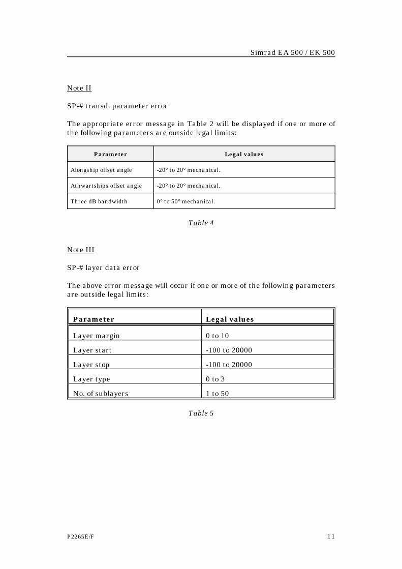
Note II
SP-# transd. parameter error
The appropriate error message in Table 2 will be displayed if one or more ofthe following parameters are outside legal limits:
Parameter Legal values
Alongship offset angle -20° to 20° mechanical.
Athwartships offset angle -20° to 20° mechanical.
Three dB bandwidth 0° to 50° mechanical.
Table 4
Note III
SP-# layer data error
The above error message will occur if one or more of the following parametersare outside legal limits:
Parameter Legal values
Layer margin 0 to 10
Layer start -100 to 20000
Layer stop -100 to 20000
Layer type 0 to 3
No. of sublayers 1 to 50
Table 5

Status and error messages
12 P2265E/F

Simrad EA 500
P2483E/B 1
EA 500 SAMPLE / PING INTERVALP2483E / 859-130088 / 4AA005
This document provides optimum ping intervals for the various frequencies.
Sample interval/ping interval
2 P2483E/B
Document revisions
Rev Documentationdepartment
Hardware/SoftwareDesign
Project/ProductManagement
Date Sign Date Sign Date Sign
B

Simrad EA 500
P2483E/B 3
List of contents
1 INTRODUCTION . . . . . . . . . . . . . . . . . . . . . . . . . . . . . . . . . . . . . . . . . . . 5
2 10 M RANGE . . . . . . . . . . . . . . . . . . . . . . . . . . . . . . . . . . . . . . . . . . . . . . . 5
3 25 M RANGE . . . . . . . . . . . . . . . . . . . . . . . . . . . . . . . . . . . . . . . . . . . . . . . 6
4 50 M RANGE . . . . . . . . . . . . . . . . . . . . . . . . . . . . . . . . . . . . . . . . . . . . . . . 6

Sample interval/ping interval
4 P2483E/B
Document history(The remainder of the information on this page is for Simrad internal use).
Revisions:
Rev. A 20.06.92 First edition.Rev. B Document updated to Simrad standards.
Simrad EA 500
P2483E/B 5
1 INTRODUCTION
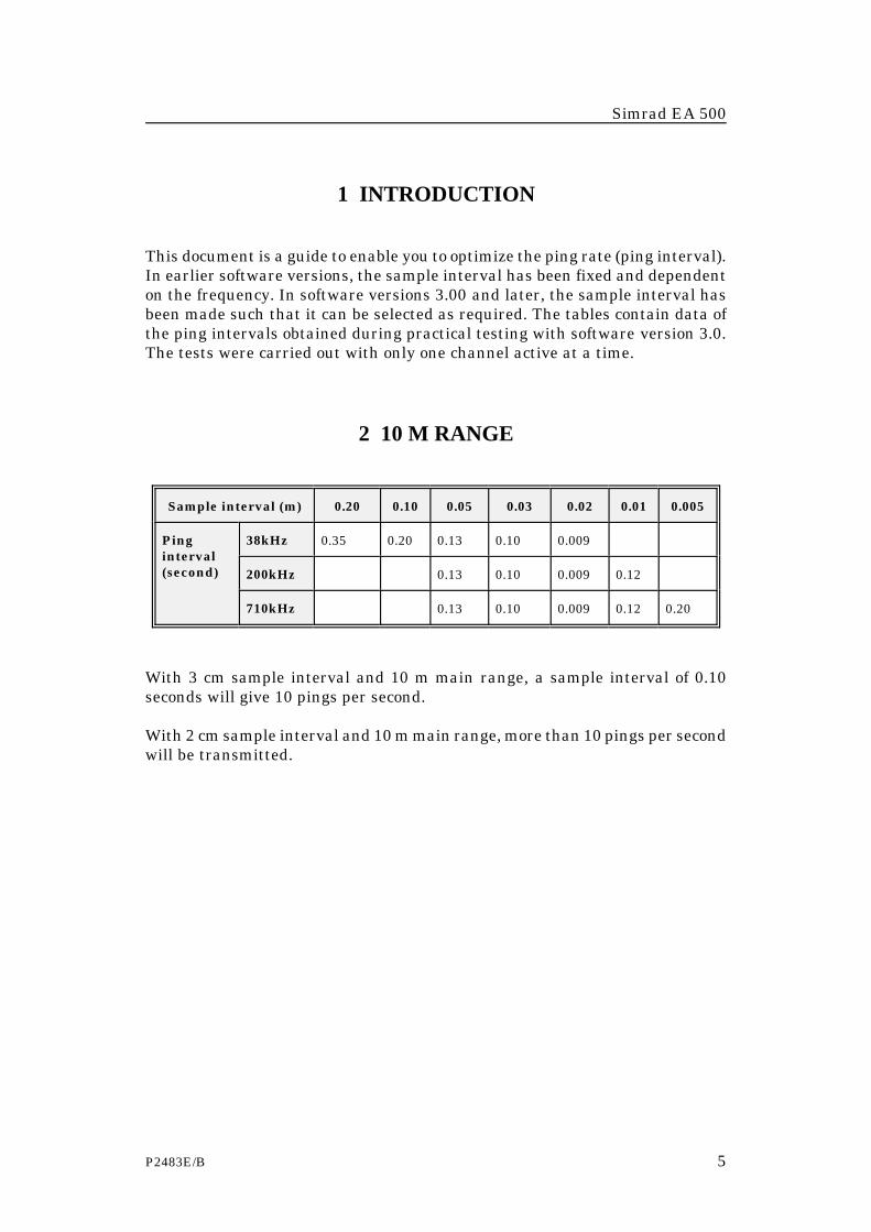
This document is a guide to enable you to optimize the ping rate (ping interval).In earlier software versions, the sample interval has been fixed and dependenton the frequency. In software versions 3.00 and later, the sample interval hasbeen made such that it can be selected as required. The tables contain data ofthe ping intervals obtained during practical testing with software version 3.0.The tests were carried out with only one channel active at a time.
2 10 M RANGE
Sample interval (m) 0.20 0.10 0.05 0.03 0.02 0.01 0.005
Pinginterval(second)
38kHz 0.35 0.20 0.13 0.10 0.009
200kHz 0.13 0.10 0.009 0.12
710kHz 0.13 0.10 0.009 0.12 0.20
With 3 cm sample interval and 10 m main range, a sample interval of 0.10seconds will give 10 pings per second.
With 2 cm sample interval and 10 m main range, more than 10 pings per secondwill be transmitted.

Sample interval/ping interval
6 P2483E/B
3 25 M RANGE
Sample interval (m) 0.20 0.10 0.05 0.03 0.02 0.01 0.005
Pinginterval(second)
38kHz 0.35 0.21 0.13 0.11 0.13
200kHz 0.13 0.11 0.13 0.21
710kHz 0.13 0.10 0.009 0.21 0.38
4 50 M RANGE
Sample interval (m) 0.20 0.10 0.05 0.03 0.02 0.01 0.005
Pinginterval(second)
38kHz 0.35 0.21 0.13 0.15 0.21
200kHz 0.13 0.15 0.21 0.35
710kHz 0.13 0.15 0.20 0.34 0.68

Simrad EA 500
P2372E/B 1
EA 500 PINGER MODEP2372E / 859-043976 / 4AA005
This document describes the 12 kHz listening transducer.

Pinger mode
2 P2372E/B
Document revisions
Rev Documentationdepartment
Hardware/SoftwareDesign
Project/ProductManagement
Date Sign Date Sign Date Sign
A 31.08.92
B 15.03.96 CL 18.03.96 OL 18.03.96 EF

Simrad EA 500
P2372E/B 3
List of contents
1 INTRODUCTION . . . . . . . . . . . . . . . . . . . . . . . . . . . . . . . . . . . . . . . . . . . 5
2 SPECIFICATIONS . . . . . . . . . . . . . . . . . . . . . . . . . . . . . . . . . . . . . . . . . . 62.1 TRANSDUCER . . . . . . . . . . . . . . . . . . . . . . . . . . . . . . . . . . . . . . . . . 62.2 TRANSCEIVER . . . . . . . . . . . . . . . . . . . . . . . . . . . . . . . . . . . . . . . . . 62.3 RANGE PERFORMANCE (12 KHZ) . . . . . . . . . . . . . . . . . . . . . . . . . 6
3 SYSTEM OPERATION . . . . . . . . . . . . . . . . . . . . . . . . . . . . . . . . . . . . . . . 7
4 TIMING STABILITY . . . . . . . . . . . . . . . . . . . . . . . . . . . . . . . . . . . . . . . . . 8

Pinger mode
4 P2372E/B
Document history(The remainder of the information on this page is for Simrad internal use).
Revisions:
Rev. A 31.08.92 Original version.Rev. B 15.03.96 Document updated and brought up to Simrad's standards.

Simrad EA 500
P2372E/B 5
1 INTRODUCTION
Simrad has developed a 12 kHz transducer for pinger listening. The transducerbeam width is approximately 50°, and the beam is circular. One or more of thethree channels of the EA 500 can be used for receiving pinger signals. Thefrequency of the transceiver channel must correspond with the pingerfrequency.
The EA 500 pinger mode may be used for tracking objects relative to thesurface/bottom or relative to each other.
Note
To avoid damaging the transducer, Simrad strongly recommendsthat you install a transceiver board specially made to be used inconjunction with the 12 kHz pinger mode transducer.

Pinger mode
6 P2372E/B
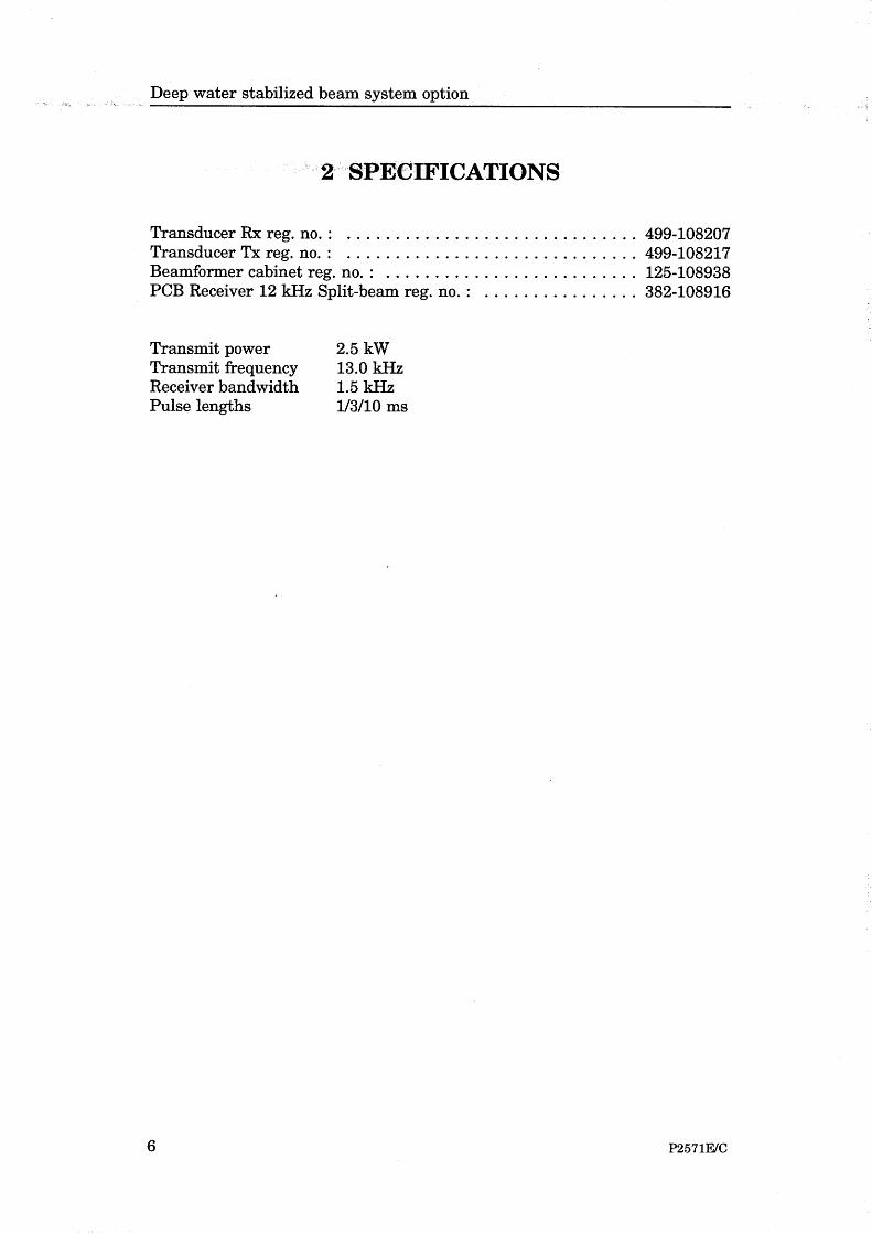
2 SPECIFICATIONS
2.1 TRANSDUCER
Transducer reg. no: . . . . . . . . . . . . . . . . . . . . . . . . . . . . . . . . . . . . . 312-083741Frequency: . . . . . . . . . . . . . . . . . . . . . . . . . . . . . . . . . . . . . . . . . . . . . . 12.0 kHzTransducer beamwidth: . . . . . . . . . . . . . . . . . . . . . . . . . . Approx. 50° circularReceiver bandwidth: . . . . . . . . . . . . . . . . . . . . . . . . . . . . . . . . . . . . . . . 1.5 kHz
2.2 TRANSCEIVER
Transceiver PCB, 12 kHz reg. no. . . . . . . . . . . . . . . . . . . . . . . . . . . 382-074824
2.3 RANGE PERFORMANCE (12 KHZ)
Assumed ship noise level: . . . . . . . . . . . . . . . . . . . . . . . 50 dB ref. 1µPA, 1 HzAssumed signal to noise level: . . . . . . . . . . . . . . . . . . . . . . Better than 10 dB
Pinger source level(rel. 1 µPa)
(dB)
Receive direction(rel. to vertical)
(°)
Max. rangedirect signal
(m)
Max rangebottom reflection
(m)
193 0 14000 7000
185 0 11000 3500
185 ±50 5000 800
185 > 70 3000 300

Simrad EA 500
P2372E/B 7
3 SYSTEM OPERATION
Select the Operation menu and set the Ping interval to a desired valuecorresponding to the pinger pulse repetition rate.
Select the desired Transceiver-# menu(s) and set Mode to Passive. This is apassive listening mode with no transmitter pulses.
The echo sounder can be operated with or without TVG (refer to the Display /Echogram-# menu). The parameter Colour gain (see the Display / Echogram-#menu) may be manipulated to obtain echograms that cover the desired signalstrength rate.

Pinger mode
8 P2372E/B
4 TIMING STABILITY
Due to the drift of the two independent clocks, one (the echo sounder and onein the pinger) the displayed pulse from a constant-depth pinger may drift slowlyover the echogram. The stability of the clock in the echo sounder is better than50 ppm, corresponding to a drift on the echogram of 4.5 m/min. A similarcontribution can be expected as a result of the clock in the pinger.


Kon
gsbe
rgS
imra
dE
A50
0O
pera
torm
anua
l/B
ase
vers
ion
Kon
gsbe
rgS
imra
dE
A50
0O
pera
torm
anua
l/B
ase
vers
ion
Kon
gsbe
rgS
imra
dE
A50
0O
pera
torm
anua
l/B
ase
vers
ion
Kon
gsbe
rgS
imra
dE
A50
0O
pera
torm
anua
l/B
ase
vers
ion