KM2530 3530 U-Maintenance
56
2BH/J 1-4-1 1-4-1 Maintenance mode The copier is equipped with a maintenance function which can be used to maintain and service the machine. (1) Executing a maintenance item Enter “10871087” using the numeric keys. Enter “001” using the cursor up/down keys or numeric keys and press the start key. Enter the maintenance item number using the cursor up/down keys or numeric keys. The selected maintenance item is run. Press the stop/clear key. Press the start key. Start End Maintenance mode is entered. The maintenance item is selected. Maintenance mode is exited. Repeat the same maintenance item? Run another maintenance item? No No Yes Yes
-
Upload
achilleos-antonis -
Category
Documents
-
view
106 -
download
3
Transcript of KM2530 3530 U-Maintenance

2BH/J
1-4-1
1-4-1 Maintenance mode
The copier is equipped with a maintenance function which can be used to maintain and service the machine.
(1) Executing a maintenance item
Enter “10871087” using the numeric keys.
Enter “001” using the cursor up/down keys or numeric keys
and press the start key.
Enter the maintenance item number using the cursor up/down keys
or numeric keys.
The selected maintenance item is run.
Press the stop/clear key.
Press the start key.
Start
End
Maintenance mode is entered.
The maintenance item is selected.
Maintenance mode is exited.
Repeat the same maintenance item?
Run another maintenance item?
No
No
Yes
Yes
2BH/J
1-4-2
General
Initialization
Drive, paperfeed, paperconveying andcooling system
Optical
High voltage
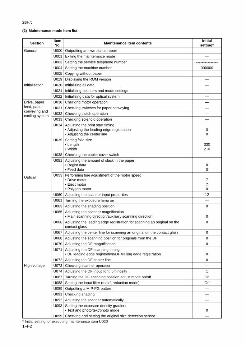
U000 Outputting an own-status report —
U001 Exiting the maintenance mode —
U003 Setting the service telephone number ***************U004 Setting the machine number 000000
U005 Copying without paper —
U019 Displaying the ROM version —
U020 Initializing all data —
U021 Initializing counters and mode settings —
U022 Initializing data for optical system —
U030 Checking motor operation —
U031 Checking switches for paper conveying —
U032 Checking clutch operation —
U033 Checking solenoid operation —
U034 Adjusting the print start timing• Adjusting the leading edge registration 0• Adjusting the center line 0
U035 Setting folio size• Length 330• Width 210
U038 Checking the copier cover switch —
U051 Adjusting the amount of slack in the paper• Regist data 0• Feed data 0
U053 Performing fine adjustment of the motor speed• Drive motor 7• Eject motor 7• Polygon motor 0
U060 Adjusting the scanner input properties 12
U061 Turning the exposure lamp on —
U063 Adjusting the shading position 0
U065 Adjusting the scanner magnification• Main scanning direction/auxiliary scanning direction 0
U066 Adjusting the leading edge registration for scanning an original on the 0contact glass
U067 Adjusting the center line for scanning an original on the contact glass 0
U068 Adjusting the scanning position for originals from the DF 0
U070 Adjusting the DF magnification 0
U071 Adjusting the DF scanning timing• DF leading edge registration/DF trailing edge registration 0
U072 Adjusting the DF center line 0
U073 Checking scanner operation —
U074 Adjusting the DF input light luminosity 1
U087 Turning the DF scanning position adjust mode on/off On
U088 Setting the input filter (moiré reduction mode) Off
U089 Outputting a MIP-PG pattern —
U091 Checking shading —
U092 Adjusting the scanner automatically —
U093 Setting the exposure density gradient• Text and photo/text/photo mode 0
U099 Checking and setting the original size detection sensor —
* Initial setting for executing maintenance item U020
SectionItem
Maintenance item contentsInitial
No. setting*
(2) Maintenance mode item list

2BH/J
1-4-3
SectionItem
Maintenance item contentsInitial
No. setting*
Developing
Fixing andcleaning
Operationpanel andsupportequipmen
Mode setting
Mode setting
U100 Checking the operation of main high voltage 184
U101 Setting high voltages• Developing bias AC component frequency at image formation 33• Developing bias AC component duty at image formation 50• Transfer control voltage 132
U110 Checking/clearing the drum count —
U112 Setting toner refresh operation• Time of toner refreshment 120• Developing bias on time 700
U113 Operating the drum refreshment —
U130 Initial setting for the developer —
U144 Setting toner loading operation MODE2
U150 Checking sensors and switches for toner —
U157 Checking/clearing the developing drive time —
U158 Checking/clearing the developing count —
U161 Setting the fixing control temperature• Control temperature during copying 155• Primary stabilization fixing temperature 120• Secondary stabilization fixing temperature 155
U162 Stabilizing fixing forcibly —
U163 Resetting the fixing problem data —
U165 Checking/clearing fixing counts —
U196 Turning the fixing heater on —
U199 Checking the fixing temperature —
U200 Turning all LEDs on —
U201 Initializing the touch panel —
U202 Setting the KMAS host monitoring system —
U203 Operating DF separately —
U204 Setting the presence or absence of a key card or key counter —
U206 Setting the presence or absence of the coin vender —
U207 Checking the operation panel keys —
U208 Setting the paper size for the large paper deck A4
U211 Setting DF type —
U217 Setting 81/2" × 13" paper —
U237 Setting finisher stack quantity —
U243 Checking the operation of the DF motors, solenoids and clutch —
U244 Checking the DF switches —
U245 Checking messages —
U246 Setting the finisher• Amount of slack in the paper 0• Booklet stapling position adjustment 0
U247 Checking the operation of large paper deck and paper feed desk —
U249 Checking the paper ejection to optional devices —
U250 Setting the maintenance cycle 500000 (35 cpm)400000 (25 cpm)
U251 Checking/clearing the maintenance count —
U252 Setting the destination Japan
U253 Switching between double and single counts Double count
U254 Turning auto start function on/off On
U255 Setting auto clear time 90
U256 Turning auto preheat/energy saver function on/off On
* Initial setting for executing maintenance item U020

SectionItem
Maintenance item contentsInitial
No. setting*
2BH/J
1-4-4
U258 Switching copy operation at toner empty detection Single mode,0
U260 Changing the copy count timing After ejection
U265 Setting OEM purchaser code —
U330 Setting the number of sheets to enter stacking mode during sort operation —
U332 Setting the size conversion factor —
U341 Specific paper feed location setting for printing function —
U342 Setting the ejection restriction On
U343 Switching between duplex/simplex copy mode Off
U344 Setting preheat/energy saver mode E 2000
U345 Setting the value for maintenance due indication —
U402 Adjusting margins of image printing —
U403 Adjusting margins for scanning an original on the contact glass —
U404 Adjusting margins for scanning an original from the DF —
U407 Adjusting the leading edge registration for memory image printing —
U901 Checking/clearing copy counts by paper feed locations —
U902 Checking/clearing finisher punch count 75000
U903 Checking/clearing the paper jam counts —
U904 Checking/clearing the service call counts —
U905 Checking/clearing counts by optional devices —
U906 Resetting partial operation control —
U908 Changing the total counter value —
U910 Clearing the black ratio data —
U911 Checking/clearing copy counts by paper sizes —
U990 Checking/clearing the time for the exposure lamp to light —
U991 Checking/clearing the scanner count —
U992 Checking or clearing the printer/fax count —
U993 Outputting a VTC-PG pattern —
* Initial setting for executing maintenance item U020
Imageprocessing
Others

1-4-5
2BH/J
U000 Outputting an own-status report
DescriptionOutputs lists of the current settings of the maintenance items, and paper jam and service call occurrences.
PurposeTo check the current setting of the maintenance items, or paper jam or service call occurrences.Before initializing or replacing the backup RAM, output a list of the current settings of the maintenance items toreenter the settings after initialization or replacement.
Method1. Press the start key. The screen for selecting an item is displayed.2. Select the item to be output. The selected item is displayed in reverse.
Display Output list
MAINTENANCE List of the current settings of the maintenance modesJAM List of the paper jam occurrencesSERVICE CALL List of the service call occurrences
3. Press the start key. The interrupt copy mode is entered and a list is output.When A4/11" × 81/2" paper is available, a report of this size is output. If not, specify the paper feed location.When output is complete, the screen for selecting an item is displayed.
CompletionPress the stop/clear key at the screen for selecting an item. The screen for selecting a maintenance item No. isdisplayed.
U001 Exiting the maintenance mode
DescriptionExits the maintenance mode and returns to the normal copy mode.
PurposeTo exit the maintenance mode.
MethodPress the start key. The normal copy mode is entered.
(3) Contents of maintenance mode items
MaintenanceDescriptionitem No.

MaintenanceDescriptionitem No.
2BH/J
1-4-6
U003 Setting the service telephone number
DescriptionSets the telephone number to be displayed when a service call code is detected.
PurposeTo set the telephone number to call service when installing the machine.
MethodPress the start key. The currently set telephone number is displayed.
Setting1. Enter a telephone number (up to 15 digits) using the numeric keys.
• To enter symbols such as hyphens and parentheses, select as required from the symbols displayed onthe touch panel as shown below. To move the cursor, press LEFT or RIGHT in the bottom row.
*(-
LEFT
#)
(Space)RIGHT
2. Press the start key. The phone number is set, and the screen for selecting a maintenance item No. isdisplayed.
CompletionTo exit this maintenance item without changing the current setting, press the stop/clear key. The screen forselecting a maintenance item No. is displayed.
U004 Setting the machine number
DescriptionDisplays and changes the machine number.
PurposeTo check or set the machine number.
MethodPress the start key. The currently set machine number is displayed.
Setting1. Enter the last six digits of the machine number using the numeric key.
Do not enter the first two digits, 3 and 7.2. Press the start key. The machine number is set, and the screen for selecting a maintenance item No. is
displayed.
CompletionTo exit this maintenance item without changing the current setting, press the stop/clear key. The screen forselecting a maintenance item No. is displayed.

2BH/J
1-4-7
MaintenanceDescriptionitem No.
U005 Copying without paper
DescriptionSimulates the copy operation without paper feed.
PurposeTo check the overall operation of the machine.
Method1. Press the start key. The screen for selecting an item is displayed.2. Select the item to be operated. The selected item is displayed in reverse.
Display Operation
PPC Only the copier operates.PPC + DF Both the copier and DF operate (continuous operation).
3. Press the interrupt key. The copy mode screen is displayed.4. Set the operation conditions required on the copy mode screen. Changes in the following settings can be
made.• Paper feed locations• Magnifications• Simplex or duplex copy mode• Number of copies: in simplex copy mode, continuous copying is performed when set to 999; in duplex
copy mode, continuous copying is performed regardless of the setting.• Copy density• Keys on the operation panel other than the energy saver (preheat) key
5. To control the paper feed pulley, remove all the paper in the drawers, or the drawers. With the paperpresent, the paper feed pulley does not operate.
6. Press the start key. The operation starts.Copy operation is simulated without paper under the set conditions. When operation is complete, thescreen for selecting an item is displayed.
7. To stop continuous operation, press the stop/clear key.
CompletionPress the stop/clear key at the screen for selecting an item. The screen for selecting a maintenance item No. isdisplayed.
U019 Displaying the ROM versionDescriptionDisplays the part number of the ROM fitted to each PCB.
PurposeTo check the part number or to decide if the ROM version is new from the last digit of the number.
MethodPress the start key. The last eight digits of the part number indicating the ROM version are displayed.
Display Description
MAIN Main ROM ICMMI Operation ROM ICLANGUAGE(Stand.) Standard language ROM ICLANGUAGE(Option) Optional language ROM ICMAIN BOOT Boot of main ROM ICMMI BOOT Boot of operation ROM ICNETWORK SCANNER Network scanner ROM IC
CompletionPress the stop/clear key. The screen for selecting a maintenance item No. is displayed.
MaintenanceDescriptionitem No.
2BH/J
1-4-8
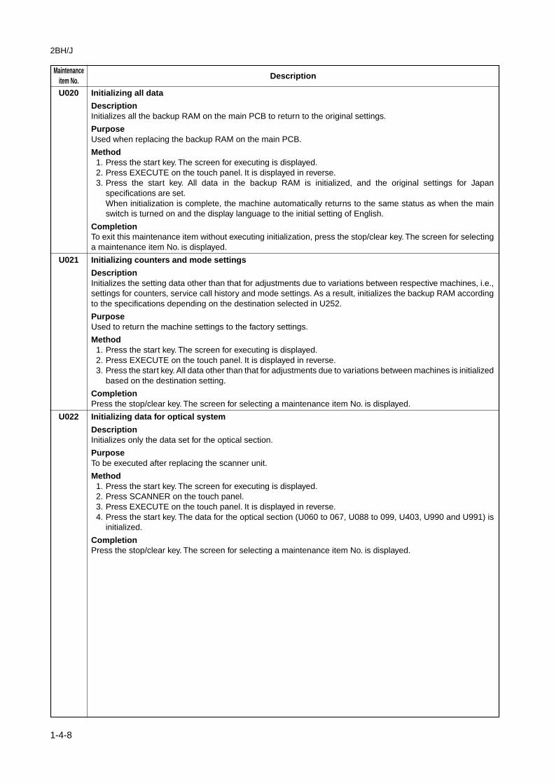
U020 Initializing all data
DescriptionInitializes all the backup RAM on the main PCB to return to the original settings.
PurposeUsed when replacing the backup RAM on the main PCB.
Method1. Press the start key. The screen for executing is displayed.2. Press EXECUTE on the touch panel. It is displayed in reverse.3. Press the start key. All data in the backup RAM is initialized, and the original settings for Japan
specifications are set.When initialization is complete, the machine automatically returns to the same status as when the mainswitch is turned on and the display language to the initial setting of English.
CompletionTo exit this maintenance item without executing initialization, press the stop/clear key. The screen for selectinga maintenance item No. is displayed.
U021 Initializing counters and mode settings
DescriptionInitializes the setting data other than that for adjustments due to variations between respective machines, i.e.,settings for counters, service call history and mode settings. As a result, initializes the backup RAM accordingto the specifications depending on the destination selected in U252.
PurposeUsed to return the machine settings to the factory settings.
Method1. Press the start key. The screen for executing is displayed.2. Press EXECUTE on the touch panel. It is displayed in reverse.3. Press the start key. All data other than that for adjustments due to variations between machines is initialized
based on the destination setting.
CompletionPress the stop/clear key. The screen for selecting a maintenance item No. is displayed.
U022 Initializing data for optical system
DescriptionInitializes only the data set for the optical section.
PurposeTo be executed after replacing the scanner unit.
Method1. Press the start key. The screen for executing is displayed.2. Press SCANNER on the touch panel.3. Press EXECUTE on the touch panel. It is displayed in reverse.4. Press the start key. The data for the optical section (U060 to 067, U088 to 099, U403, U990 and U991) is
initialized.
CompletionPress the stop/clear key. The screen for selecting a maintenance item No. is displayed.

2BH/J
1-4-9
MaintenanceDescriptionitem No.
U030 Checking motor operation
DescriptionDrives each motor.
PurposeTo check the operation of each motor.
Method1. Press the start key. The screen for selecting an item is displayed.2. Select the motor to be operated. The selected item is displayed in reverse and the operation starts.
Display Operation
FEED Paper feed motor operatesMAIN Drive motor operatesEJECT(FW) Eject motor rotates forwardEJECT(REV) Eject motor rotates in reverse
3. To stop operation, press the stop/clear key.
CompletionPress the stop key after operation stops. The screen for selecting a maintenance item No. is displayed.
U031 Checking switches for paper conveying
DescriptionDisplays the on-off status of each paper detection switch on the paper path.
PurposeTo check if the switches for paper conveying operate correctly.
Method1. Press the start key. A list of the switches, the on-off status of which can be checked, are displayed.2. Turn each switch on and off manually to check the status.
When the on-status of a switch is detected, that switch is displayed in reverse.
Display Switches
F1 Feed switch 1 (FSW1)F2 Feed switch 2 (FSW2)F3 Feed switch 3 (FSW3)BYP Bypass feed switch (BYPFSW)RES Registration switch (RSW)EJE Eject switch (ESW)BRA Feedshift switch (FSSW)DUP Duplex paper conveying switch (DUPPCSW)*JOB Job separator eject switch (JBESW)*
*Optional.
CompletionPress the stop/clear key. The screen for selecting a maintenance item No. is displayed.
MaintenanceDescriptionitem No.
2BH/J
1-4-10
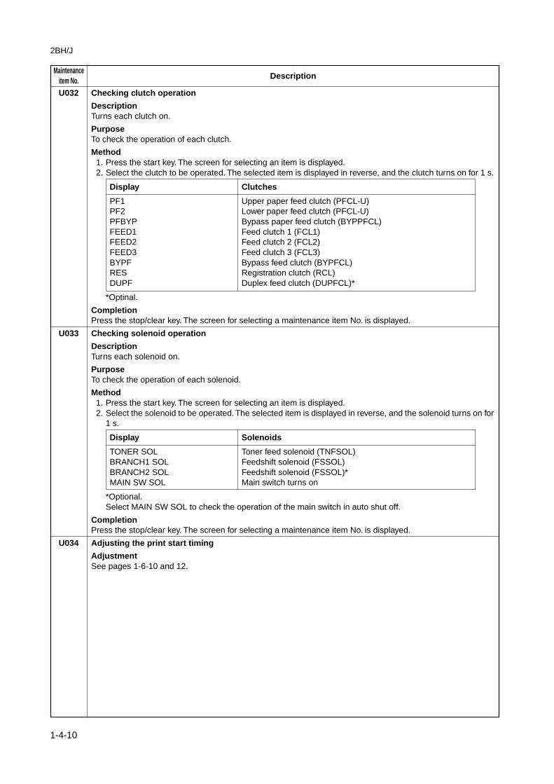
U032 Checking clutch operation
DescriptionTurns each clutch on.
PurposeTo check the operation of each clutch.
Method1. Press the start key. The screen for selecting an item is displayed.2. Select the clutch to be operated. The selected item is displayed in reverse, and the clutch turns on for 1 s.
Display Clutches
PF1 Upper paper feed clutch (PFCL-U)PF2 Lower paper feed clutch (PFCL-U)PFBYP Bypass paper feed clutch (BYPPFCL)FEED1 Feed clutch 1 (FCL1)FEED2 Feed clutch 2 (FCL2)FEED3 Feed clutch 3 (FCL3)BYPF Bypass feed clutch (BYPFCL)RES Registration clutch (RCL)DUPF Duplex feed clutch (DUPFCL)*
*Optinal.
CompletionPress the stop/clear key. The screen for selecting a maintenance item No. is displayed.
U033 Checking solenoid operation
DescriptionTurns each solenoid on.
PurposeTo check the operation of each solenoid.
Method1. Press the start key. The screen for selecting an item is displayed.2. Select the solenoid to be operated. The selected item is displayed in reverse, and the solenoid turns on for
1 s.
Display Solenoids
TONER SOL Toner feed solenoid (TNFSOL)BRANCH1 SOL Feedshift solenoid (FSSOL)BRANCH2 SOL Feedshift solenoid (FSSOL)*MAIN SW SOL Main switch turns on
*Optional.Select MAIN SW SOL to check the operation of the main switch in auto shut off.
CompletionPress the stop/clear key. The screen for selecting a maintenance item No. is displayed.
U034 Adjusting the print start timing
AdjustmentSee pages 1-6-10 and 12.
2BH/J
1-4-11
MaintenanceDescriptionitem No.
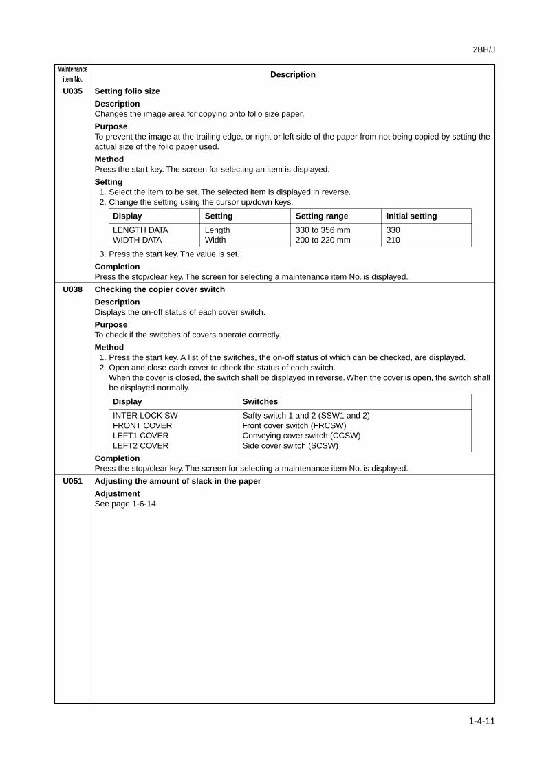
U035 Setting folio size
DescriptionChanges the image area for copying onto folio size paper.
PurposeTo prevent the image at the trailing edge, or right or left side of the paper from not being copied by setting theactual size of the folio paper used.
MethodPress the start key. The screen for selecting an item is displayed.
Setting1. Select the item to be set. The selected item is displayed in reverse.2. Change the setting using the cursor up/down keys.
Display Setting Setting range Initial setting
LENGTH DATA Length 330 to 356 mm 330WIDTH DATA Width 200 to 220 mm 210
3. Press the start key. The value is set.
CompletionPress the stop/clear key. The screen for selecting a maintenance item No. is displayed.
U038 Checking the copier cover switch
DescriptionDisplays the on-off status of each cover switch.
PurposeTo check if the switches of covers operate correctly.
Method1. Press the start key. A list of the switches, the on-off status of which can be checked, are displayed.2. Open and close each cover to check the status of each switch.
When the cover is closed, the switch shall be displayed in reverse. When the cover is open, the switch shallbe displayed normally.
Display Switches
INTER LOCK SW Safty switch 1 and 2 (SSW1 and 2)FRONT COVER Front cover switch (FRCSW)LEFT1 COVER Conveying cover switch (CCSW)LEFT2 COVER Side cover switch (SCSW)
CompletionPress the stop/clear key. The screen for selecting a maintenance item No. is displayed.
U051 Adjusting the amount of slack in the paper
AdjustmentSee page 1-6-14.
MaintenanceDescriptionitem No.
2BH/J
1-4-12
U053 Performing fine adjustment of the motor speed
DescriptionPerforms fine adjustment of the speeds of the motors.
PurposeUsed to adjust the speed of the respective motors when the magnification is not correct.
MethodPress the start key. The screen for selecting an item is displayed.
Setting1. Select the item to be set. The selected item is displayed in reverse.2. Change the setting using the cursor up/down keys.
Display Description Setting range Initial setting
MAIN MOTOR Drive motor speed adjustment 0 to +14 7EJECT MOTOR Eject motor speed adjustment 0 to +14 7POLYGON MOTOR Polygon motor speed adjustment -20 to +20 0
MAIN MOTOR /EJECT MOTORIncreasing the setting makes the image longer in the auxiliary scanning direction, and decreasing it makesthe image shorter in the auxiliary scanning direction.POLYGON MOTORIncreasing the setting makes the image longer in the main scanning direction and shorter in the auxiliaryscanning direction; decreasing the setting makes the image shorter in the main scanning direction andlonger in the auxiliary scanning direction.EJECT MOTORNormally no change is necessary but this can be used as countermeasures against wrinkles (waving) ofpaper.
3. Press the start key. The value is set.
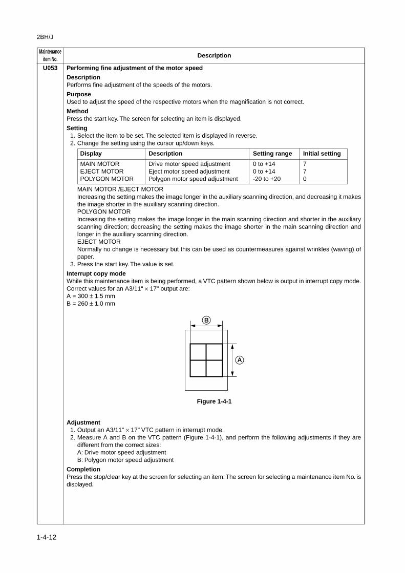
Interrupt copy modeWhile this maintenance item is being performed, a VTC pattern shown below is output in interrupt copy mode.Correct values for an A3/11" × 17" output are:A = 300 ± 1.5 mmB = 260 ± 1.0 mm
Figure 1-4-1
Adjustment1. Output an A3/11" × 17" VTC pattern in interrupt mode.2. Measure A and B on the VTC pattern (Figure 1-4-1), and perform the following adjustments if they are
different from the correct sizes:A: Drive motor speed adjustmentB: Polygon motor speed adjustment
CompletionPress the stop/clear key at the screen for selecting an item. The screen for selecting a maintenance item No. isdisplayed.

2BH/J
1-4-13
MaintenanceDescriptionitem No.
U060 Adjusting the scanner input properties
DescriptionAdjusts the image scanning density in text, text and photo, or photo mode.
PurposeUsed when the entire image appears too dark or light.
MethodPress the start key. The screen for executing is displayed.
Setting1. Change the setting using the cursor up/down keys.
Descrition Setting range Initial setting
Image scannnig density 0 to +24 12
Increasing the setting makes the density lower, and decreasing it makes the density higher.2. Press the start key. The value is set.
Interrupt copy modeWhile this maintenance item is being performed, copying from an original can be made in interrupt copy mode.
CompletionPress the stop/clear key at the screen for selecting an item. The screen for selecting a maintenance item No. isdisplayed.
CautionThe following settings are also reset to the initial values by performing this maintenance item:• Exposure density gradient set in maintenance mode (U093)• Exposure set in the copy default item of the copier management mode
U061 Turning the exposure lamp on
DescriptionTurns the exposure lamp on.
PurposeTo check the exposure lamp.
Method1. Press the start key. The screen for executing is displayed.2. Press the start key. The exposure lamp lights.3. To turn the exposure lamp off, press the stop/clear key.
CompletionPress the stop/clear key. The screen for selecting a maintenance item No. is displayed.
MaintenanceDescriptionitem No.
2BH/J
1-4-14
U063 Adjusting the shading position
DescriptionChanges the shading position.
PurposeUsed when white lines continue to appear longitudinally on the image after the shading plate is cleaned. This isdue to flaws or stains inside the shading plate. To prevent this problem, the shading position should be changedso that shading is possible without being affected by the flaws or stains.
Method1. Press the start key. The screen for adjustment is displayed.2. Change the setting using the cursor up/down keys.
Description Setting range Initial setting Change in value per step
Shading position –5 to +5 0 0.17 mm
Increasing the setting moves the shading position toward the machine right, and decreasing it moves theposition toward the machine left.
3. Press the start key. The value is set.
Interrupt copy modeWhile this maintenance item is being performed, copying from an original can be made in interrupt copy mode.
CompletionPress the stop/clear key at the screen for adjustment. The screen for selecting a maintenance item No. isdisplayed.
U065 Adjusting the scanner magnification
AdjustmentSee pages 1-6-27 and 28.
U066 Adjusting the leading edge registration for scanning an original on the contact glass
AdjustmentSee page 1-6-29.
U067 Adjusting the center line for scanning an original on the contact glass
AdjustmentSee page 1-6-30.
U068 Adjusting the scanning position for originals from the DF
DescriptionAdjusts the position for scanning originals from the DF.
PurposeUsed when there is a regular error between the leading edges of the original and the copy image when the DFis used.
MethodPress the start key. The screen for executing is displayed.
Setting1. Change the setting using the cursor up/down keys.
Description Setting range Initial setting Change in value per step
Scanning position –17 to +17 0 0.254 mm
Increasing the setting moves the image backward, and decreasing it moves the image forward.2. Press the start key. The value is set.
CompletionPress the stop/clear key. The screen for selecting a maintenance item No. is displayed.
2BH/J
1-4-15
MaintenanceDescriptionitem No.
U070 Adjusting the DF magnification
DescriptionAdjusts the DF original scanning speed.
PurposeTo be executed if the correct magnification is not obtained in the auxiliary scanning direction when the optionalDF is used.
CautionBefore making this adjustment, ensure that the following adjustments have been made in maintenance mode.
U053 U065 U070
MethodPress the start key. The screen for executing is displayed.
Setting1. Change the setting using the cursor up/down keys.
Description Setting range Initial setting Change in value per step
Original conveying motor speed –25 to +25 0 0.1%
Increasing the setting makes the image longer, and decreasing it makes the image shorter.2. Press the start key. The value is set.
Interrupt copy modeWhile this maintenance item is being performed, copying from an original can be made in interrupt copy mode.
CompletionPress the stop/clear key at the screen for selecting an item. The screen for selecting a maintenance item No. isdisplayed.

MaintenanceDescriptionitem No.
2BH/J
1-4-16
U071 Adjusting the DF scanning timing
DescriptionAdjusts the DF original scanning timing.
PurposeTo be executed if there is a regular error between the leading or trailing edges of the original and the copyimage when the optional DF is used.
CautionBefore making this adjustment, ensure that the following adjustments have been made in maintenance mode.
U034 U066 U071
MethodPress the start key. The screen for selecting an item is displayed.
Setting1. Select the item to be set. The selected item is displayed in reverse.2. Change the setting using the cursor up/down keys.
Display Description Setting range Initial settingChange invalue per step
LEAD EDGE ADJ DF leading edge registration –32 to +32 0 0.17 mmTRAIL EDGE ADJ DF trailing edge registration –32 to +32 0 0.17 mm
Increasing the setting moves the copy image backward, and decreasing it moves the copy image forward.3. Press the start key. The value is set.
Interrupt copy modeWhile this maintenance item is being performed, copying from an original can be made in interrupt copy mode.
Adjustment1. In interrupt copy mode, make a copy using the DF.2. Check the copy image and adjust the registration as follows.
For copy example 1, increase the setting of LEAD EDGE ADJ.For copy example 2, decrease the setting of LEAD EDGE ADJ.
Original Copy example 1
Copyexample 2
Figure 1-4-2
CompletionPress the stop/clear key at the screen for selecting an item. The screen for selecting a maintenance item No. isdisplayed.

2BH/J
1-4-17
MaintenanceDescriptionitem No.
U072 Adjusting the DF center line
DescriptionAdjusts the scanning start position for the DF original.
PurposeTo be executed if there is a regular error between the centers of the original and the copy image when theoptional DF is used.
CautionBefore making this adjustment, ensure that the following adjustments have been made in maintenance mode.
U034 U067 U072
MethodPress the start key. The screen for executing is displayed.
Setting1. Change the setting using the cursor up/down keys.
Description Setting range Initial setting Change in value per step
DF center line –39 to +39 0 0.17 mm
Increasing the setting moves the image to the right, and decreasing it moves the image to the left.2. Press the start key. The value is set.
Interrupt copy modeWhile this maintenance item is being performed, copying from an original can be made in interrupt copy mode.
Adjustment1. In interrupt copy mode, make a copy using the DF.2. Check the copy image and adjust the center line as follows.
For copy example 1, increase the setting.For copy example 2, decrease the setting.
Original Copy example 1
Copyexample 2
Reference
Figure 1-4-3
CompletionPress the stop/clear key at the screen for selecting an item. The screen for selecting a maintenance item No. isdisplayed.

MaintenanceDescriptionitem No.
2BH/J
1-4-18
U073 Checking scanner operation
DescriptionSimulates the scanner operation under arbitrary conditions.
PurposeTo check scanner operation.
Method1. Press the start key. The screen for selecting an item is displayed.2. Select the item to be changed. The selected item is displayed in reverse.3. Change the setting using the cursor up/down keys.
Display Operating conditions Setting range
ZOOM Magnification 100 to 400%SIZE Original size See below.LAMP On and off of the exposure lamp 0 (off) or 1 (on)
Original sizes for each setting in SIZE
Setting Paper size Setting Paper size
8 A4 42 A5R9 B5 47 Folio24 11" × 81/2" 52 11" × 17"36 A3 53 11" × 15"39 B4 55 81/2" × 14"40 A4R 56 81/2" × 11"41 B5R 58 51/2" × 81/2"
4. Press the strat key. The setting is set.5. Press the interrupt key. The copy mode screen is displayed.6. Press the start key. Scanning starts under the selected conditions.7. To stop operation, press the stop/clear key.
CompletionPress the stop/clear key when scanning stops. The screen for selecting a maintenance item No. is displayed.
U074 Adjusting the DF input light luminosity
DescriptionAdjusts the luminosity of the exposure lamp for scanning originals from the optional DF.
PurposeUsed if the exposure amount differs significantly between when scanning an original on the contact glass andwhen scanning an original from the DF.
MethodPress the start key. The screen for executing is displayed.
Setting1. Change the setting using the cursor up/down keys.
Description Setting range Initial setting
DF input light luminosity 0 to 8 1
Increasing the setting makes the luminosity higher, and decreasing it makes the luminosity lower.2. Press the start key. The value is set.
Interrupt copy modeWhile this maintenance item is being performed, copying from an original can be made in interrupt copy mode.
CompletionPress the stop/clear key at the screen for selecting an item. The screen for selecting a maintenance item No. isdisplayed.

2BH/J
1-4-19
MaintenanceDescriptionitem No.
U087 Turning the DF scanning position adjust mode on/off
DescriptionTurns on or off the DF scanning position adjust mode, in which the DF original scanning position is adjustedautomatically by determining the presence or absence of dust on the slit glass. Also changes the referencedata for identifying dust.
ReferenceIn the DF original scanning position adjust mode, the presence or absence of dust is determined by comparingthe scan data of the original trailing edge and that taken after the original is conveyed past the DF originalscanning position. If dust is identified, the DF original scanning position is adjusted for the following originals.
PurposeUsed to prevent appearance of black lines due to dust adhering in the original scanning position on the slitglass when the DF is used.
Method1. Press the start key. The screen for selecting an item is displayed.2. Select the item to be set and press the start key.
Display Description
ON/OFF Setting the mode on/offDATA Setting the reference data for identifying dust
Setting the mode on/off1. Select ON or OFF. The selected item is displayed in reverse.
Display Description
ON DF scanning position adjust mode onOFF DF scanning position adjust mode off
Initial setting: ON2. Press the start key. The setting is set. The screen for selecting an item is displayed.
Setting the reference data for identifying dustAvailable only when the mode is turned on.1.Change the setting using the cursor up/down keys.
Description Setting range Initial setting
Minimum density to be regarded as dust 10 to 95 35
ExampleThe figure indicates the density in 256 levels of gray (0: white, 255: black). When the setting is 35, data ofthe level of 35 or higher is regarded as dust and data of lower level is regarded as the background (scandata taken when there is no original).
2. Press the start key. The value is set.3. To return to the screen for selecting an item, press the stop/clear key.
CompletionPress the stop/clear key at the screen for selecting an item. The screen for selecting a maintenance item No. isdisplayed.

MaintenanceDescriptionitem No.
2BH/J
1-4-20
U088 Setting the input filter (moiré reduction mode)
DescriptionTurns moiré reduction mode on and off by switching the input filter on and off.
PurposeUsed to prevent regular density unevenness (moiré) on halftone image areas of the copy image in text modeand text and photo mode. Such moiré is more likely to appear when an enlargement or reduction copy is madein text mode from an original containing large halftone image areas.
MethodPress the start key. The screen for selecting an item is displayed.
Setting1. Select ON or OFF. The selected item is displayed in reverse.
Display Description
ON Moiré reduction modeOFF Normal copy mode
Initial setting: OFFIf moiré on the copy image is significant, change the setting to ON. Note that when the moiré reductionmode is turned on, the resolution may be slightly reduced.
2. Press the start key. The value is set. The screen for selecting a maintenance item No. is displayed.
CompletionTo exit this maintenance item without changing the current setting, press the stop/clear key. The screen forselecting a maintenance item No. is displayed.
U089 Outputting a MIP-PG pattern
DescriptionSelects and outputs the MIP-PG pattern created in the copier.
PurposeWhen performing respective image printing adjustments, used to check the machine status apart from that ofthe scanner with a non-scanned output MIP-PG pattern.
Method1. Press the start key.2. Select the MIP-PG pattern to be output.
Display Description Adjusting range
GRAYSCALE Gray scale –MONO-LEVEL Mono level 0 to 255256-LEVEL 256 level –1dot-LINE 1 dot level –
3. Press the printer key to set the pattern output mode.4. Press the start key. A MIP-PG pattern is output.
CompletionPress the stop/reset key. The screen for selecting a maintenance item No. is displayed.

2BH/J
1-4-21
MaintenanceDescriptionitem No.
U091 Checking shading
DescriptionPerforms scanning under the same conditions as before and after shading is performed, displaying the originalscanning values at nine points of the contact glass.
PurposeTo check the change in original scanning values before and after shading. The results may be used to decidethe causes for fixing unevenness (uneven density) of the gray area of an image: either due to optical (shadingor CCD) or other problems.Also to check the causes for a white or black line appearing longitudinally.
Method1. Press the start key. The screen for selecting an item is displayed.2. Select the item to be operated. The selected item is displayed in reverse.
Display Description
SHD BEFORE Performs scanning before shading and displays the result.SHD AFTER Performs scanning after shading and displays the result.
3. Press the start key. Scanning is performed under the selected conditions and the result is displayed.When scanning is performed before shading, the scan value at the machine center should be slightlydifferent from those at the machine front and rear. When scanning is performed after shading, there shouldbe no difference between respective values. Any differences between the values at machine front and rearindicates that scanner problem causes the fixing unevenness.If the displayed results indicate no shading problems, the fixing unevenness (uneven copy density) iscaused by factors other than in the scanner section (shading or CCD).If a black line appears, the cause may assumed to be based on the results of the scanning operation beforeshading: if a white line appears, they may be assumed based on the results of the scanning operation aftershading. Note that depending on the thickness and location of the black or white line, it may not be possibleto use this method to determine the cause. This is because the displayed values obtained from scanning atthe limit of nine points are insufficient to provide significant information.
20 mm from the machine left
200 mm from the machine left
400 mm from the machine left
Machine center100 mm from the machine center toward machine front
100 mm from the machine center toward machine rear
Figure 1-4-4
4. To return to the screen for selecting an item, press the stop/clear key.
CompletionPress the stop/clear key at the screen for selecting an item. The screen for entering a maintenance item isdisplayed.

MaintenanceDescriptionitem No.
2BH/J
1-4-22
U092 Adjusting the scanner automatically
DescriptionMakes auto scanner adjustments in the order below using the specified original.• Adjusting the scanner center line (U067)• Adjusting the scanner leading edge registration (U066)• Adjusting scanner magnification in the auxiliary direction (U065)When this maintenance item is performed, the settings in U065, U066 and U067 are also changed.
PurposeUsed to make respective auto adjustments for the scanner.
Method1. Place the specified original (P/N: 2A068020) on the contact glass.2. Press the start key. The screen for executing is displayed.3. Press the start key. Auto adjustment starts. When adjustment is complete, each adjusted value is displayed.
Display Description
SCAN CENTER Scanner center lineSCAN TIMING Scanner leading edge registrationSUB SCAN Scanner magnification in the auxiliary scanning direction
If a problem occurs during auto adjustment, DATA: XX (XX is replaced by an error code) is displayed andoperation stops. Should this happen, determine the details of the problem and either repeat the procedurefrom the beginning, or adjust the remaining items manually by running the corresponding maintenanceitems.
CompletionPress the stop/clear key after auto adjustment is complete. The screen for selecting a maintenance item No. isdisplayed.If the stop/clear key is pressed during auto adjustment, adjustment stops and no settings are changed.
2BH/J
1-4-23
MaintenanceDescriptionitem No.
U093 Setting the exposure density gradient
DescriptionChanges the exposure density gradient in manual density mode, depending on respective image modes (text,text and photo, photo).
PurposeTo set how the image density is altered by a change of one step in the manual density adjustment. Also used tomake copy image darker or lighter.
Start1. Press the start key. The screen for selecting an item is displayed.2. Select the image mode to be adjusted and press the start key. The screen for the selected item is displayed.
Display Description
MIXED Density in text and photo modeTEXT Density in text modePHOTO Density in photo mode
Setting1. Select the item to be adjusted. The selected item is displayed in reverse.2. Adjust the setting using the cursor up/down keys.
Display Description Setting range Initial setting
DARKER Change in density when manual density is set dark 0 to 3 0LIGHTER Change in density when manual density is set light 0 to 3 0
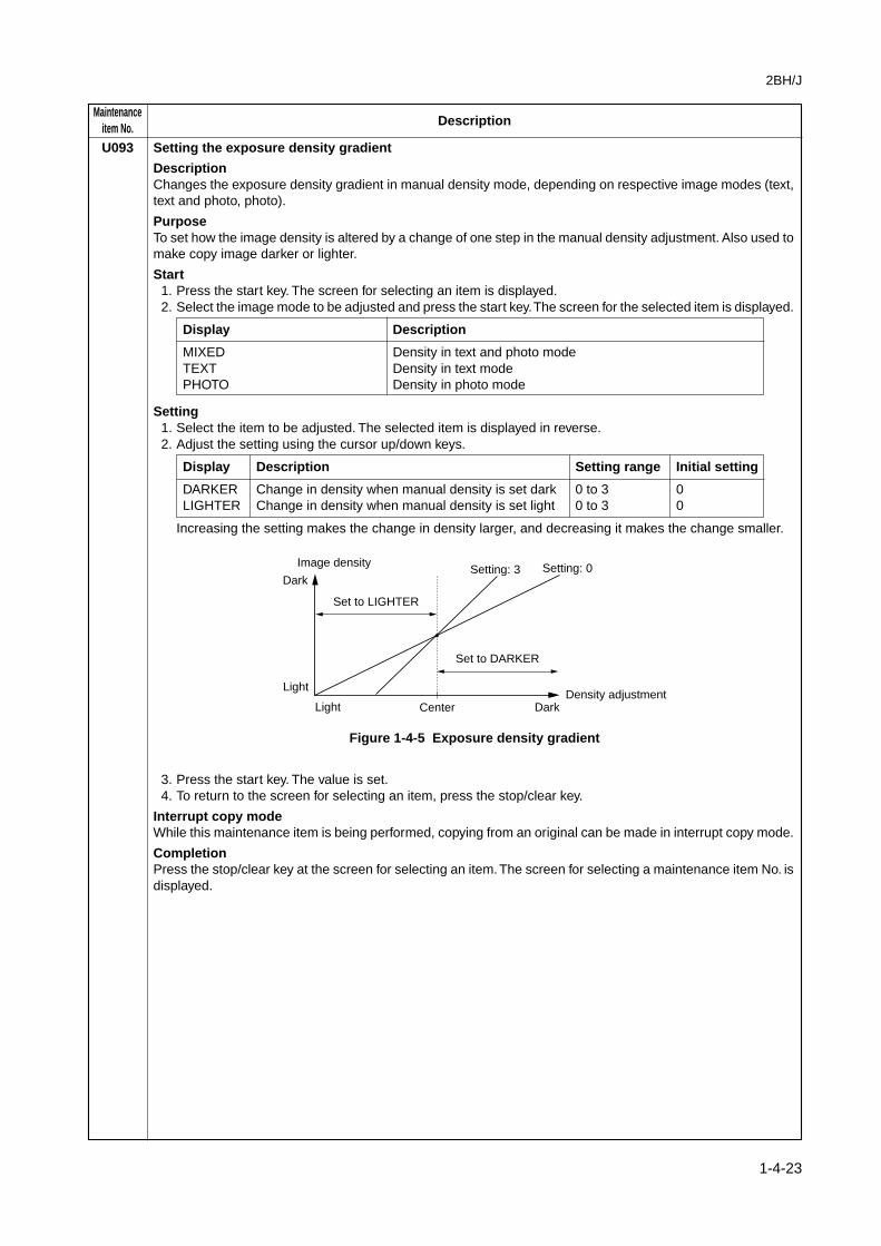
Increasing the setting makes the change in density larger, and decreasing it makes the change smaller.
Image density
Density adjustment
Dark
Light
Light Center Dark
Setting: 0Setting: 3
Set to DARKER
Set to LIGHTER
Figure 1-4-5 Exposure density gradient
3. Press the start key. The value is set.4. To return to the screen for selecting an item, press the stop/clear key.
Interrupt copy modeWhile this maintenance item is being performed, copying from an original can be made in interrupt copy mode.
CompletionPress the stop/clear key at the screen for selecting an item. The screen for selecting a maintenance item No. isdisplayed.

MaintenanceDescriptionitem No.
2BH/J
1-4-24
U099 Checking and setting the original size detection sensor
DescriptionChecks the operation of the original size detection sensor and sets the sensing threshold value.
PurposeTo adjust the sensitiveness of the sensor and size judgement time if the original size detection sensormalfunctions frequently due to incident light or the like.
Start1. Press the start key. The screen for selecting an item is displayed.2. Select an item and press the start key. The screen for executing each item is displayed.
Display Description
DATA Displaying detection sensor transmission dataB/W LEVEL Setting detection sensor threshold value
Setting original size judgment time
Method to display the data for the sensor1. Press the start key. The detection sensor transmission data is displayed.
: 123 123 123
: 123 123 123
: 255 255 255
Rear of machine
Center of machine
Front of machine
Figure 1-4-6
2. To return to the screen for selecting an item, press the stop/clear key.
Setting1. Select an item to be set.
Display Description Setting range Initial setting
LEVEL Detection sensor threshold value 0 to 255 170WAIT TIME Original size judgment time* 0 to 100 50ORIG. AREA Original size detection position display (mm) 0 to 350 –SIZE Detected original size display 0 to 63 –
* Time from activation of the original detection switch (ODSW) to original size judgment
Method to set the detection threshold value1. Adjust the preset value using the cursor up/down keys.
* A larger value increases the sensor sensitivity, and a smaller value decreases it.2. Press the start key. The value is set.3. To return to the screen for selecting an item, press the stop/clear key.
Method to set the original size judgment time1. Adjust the preset value using the cursor up/down keys.
* A larger value increases the original size judgment time, and a smaller value decreases it.2. Press the start key. The value is set.3. To return to the screen for selecting an item, press the stop/clear key.
CompletionPress the stop/clear key at the screen for selecting an item. The screen for maintenance item No. is displayed.

2BH/J
1-4-25
MaintenanceDescriptionitem No.
U100 Checking the operation of main high voltage
DescriptionPerforms main charging.
PurposeTo check main charging.
StartPress the start key. The screen for selecting an item is displayed.
Display Description
MC DATA Turning the main charger onON TIME(SEC) Turning the main charger on and the laser scanner unit on and off
Method1. Select the item to be operated.2. Press the start key. The selected operation starts.3. To stop operation, press the stop/clear key.
CompletionPress the stop/clear key at the screen for selecting an item when main charger output stops. The screen forselecting a maintenance item No. is displayed.
U101 Setting high voltages
DescriptionChanges the developing bias voltage and transfer voltage by changing the developing bias control voltage andtransfer control voltage.
PurposeTo check or change the developing bias and transfer voltage.
MethodPress the start key. The screen for selecting an item is displayed.
Setting1. Select the item to be set. The selected item is displayed in reverse.2. Change the setting using the cursor up/down keys.
Display Description Setting range Initial setting
DEV BIAS Developing bias AC component frequency 0 to 255 33at image formation
DEV DUTY Developing bias AC component duty 0 to 100 50at image formation
TC DATA Transfer control voltage 0 to 255 132
Increasing the DEV BIAS setting makes the image darker; decreasing it makes the image lighter.Increasing the DEV DUTY setting makes the image lighter; decreasing it makes the image darker.Increasing the TC DATA setting makes the transfer voltage higher, and decreasing it makes the voltagelower.
3. Press the start key. The value is set.
Interrupt copy modeWhile this maintenance item is being performed, copying from an original can be made in interrupt copy mode.
CompletionPress the stop/clear key. The screen for selecting a maintenance item No. is displayed.

MaintenanceDescriptionitem No.
2BH/J
1-4-26
U110 Checking/clearing the drum count
DescriptionDisplays the drum counts for checking, clearing or changing the figure, which is used as a reference whencorrecting the main charger potential output.
PurposeTo check the drum status. Also used to clear the count after replacing the drum during regular maintenance.Since the count was cleared before shipping, do not clear it when installing.
MethodPress the start key. The drum counter count is displayed.
Clearing1. Press the reset key.2. Press the start key. The count is cleared, and the screen for selecting a maintenance item No. is displayed.
Setting1. Enter a six-digit count using the numeric keys.2. Press the start key. The count is set, and the screen for selecting a maintenance item No. is displayed.
CompletionTo exit the maintenance mode without changing the count, press the stop/clear key. The screen for selecting amaintenance item No. is displayed.
U112 Setting toner refresh operation
DescriptionSets the drum refresh operation time and the developing bias on time at power on and after copying.
PurposeTo change the drum refresh operation time and the developing bias on time at power on and after copying ifimage flow level is low.
MethodPress the start key. The screen for executing is displayed.
Setting1. Select the item to be set. The selected item is displayed in reverse.2. Change the setting using the cursor up/down keys.
Display Description Setting range Initial setting
ON TIME(SEC) toner refresh operation time 50 to 150(sec) 120BIAS TIME(MSEC) Developing bias on time 500 to 1000(msec) 700
3. Press the start key. The value is set.
CompletionPress the stop/clear key. The screen for selecting a maintenance item No. is displayed.
2BH/J
1-4-27
MaintenanceDescriptionitem No.
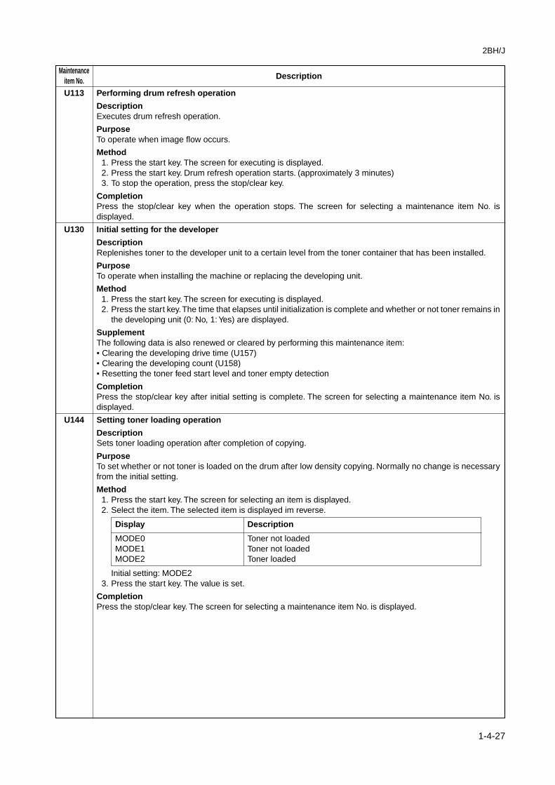
U113 Performing drum refresh operation
DescriptionExecutes drum refresh operation.
PurposeTo operate when image flow occurs.
Method1. Press the start key. The screen for executing is displayed.2. Press the start key. Drum refresh operation starts. (approximately 3 minutes)3. To stop the operation, press the stop/clear key.
CompletionPress the stop/clear key when the operation stops. The screen for selecting a maintenance item No. isdisplayed.
U130 Initial setting for the developer
DescriptionReplenishes toner to the developer unit to a certain level from the toner container that has been installed.
PurposeTo operate when installing the machine or replacing the developing unit.
Method1. Press the start key. The screen for executing is displayed.2. Press the start key. The time that elapses until initialization is complete and whether or not toner remains in
the developing unit (0: No, 1: Yes) are displayed.
SupplementThe following data is also renewed or cleared by performing this maintenance item:• Clearing the developing drive time (U157)• Clearing the developing count (U158)• Resetting the toner feed start level and toner empty detection
CompletionPress the stop/clear key after initial setting is complete. The screen for selecting a maintenance item No. isdisplayed.
U144 Setting toner loading operation
DescriptionSets toner loading operation after completion of copying.
PurposeTo set whether or not toner is loaded on the drum after low density copying. Normally no change is necessaryfrom the initial setting.
Method1. Press the start key. The screen for selecting an item is displayed.2. Select the item. The selected item is displayed im reverse.
Display Description
MODE0 Toner not loadedMODE1 Toner not loadedMODE2 Toner loaded
Initial setting: MODE23. Press the start key. The value is set.
CompletionPress the stop/clear key. The screen for selecting a maintenance item No. is displayed.
MaintenanceDescriptionitem No.
2BH/J
1-4-28
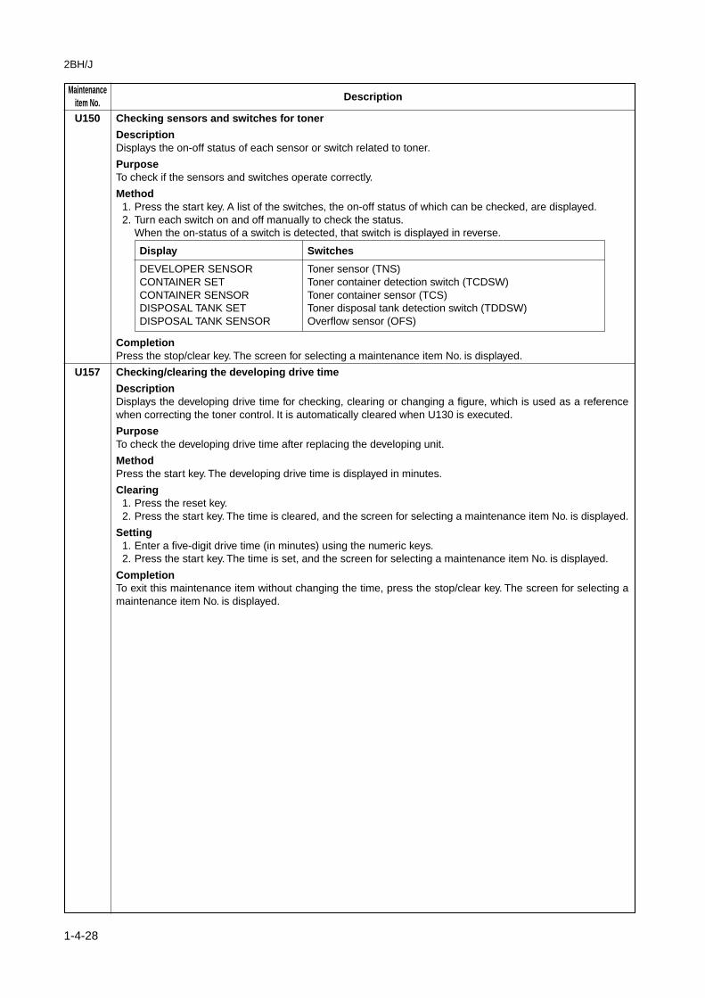
U150 Checking sensors and switches for toner
DescriptionDisplays the on-off status of each sensor or switch related to toner.
PurposeTo check if the sensors and switches operate correctly.
Method1. Press the start key. A list of the switches, the on-off status of which can be checked, are displayed.2. Turn each switch on and off manually to check the status.
When the on-status of a switch is detected, that switch is displayed in reverse.
Display Switches
DEVELOPER SENSOR Toner sensor (TNS)CONTAINER SET Toner container detection switch (TCDSW)CONTAINER SENSOR Toner container sensor (TCS)DISPOSAL TANK SET Toner disposal tank detection switch (TDDSW)DISPOSAL TANK SENSOR Overflow sensor (OFS)
CompletionPress the stop/clear key. The screen for selecting a maintenance item No. is displayed.
U157 Checking/clearing the developing drive time
DescriptionDisplays the developing drive time for checking, clearing or changing a figure, which is used as a referencewhen correcting the toner control. It is automatically cleared when U130 is executed.
PurposeTo check the developing drive time after replacing the developing unit.
MethodPress the start key. The developing drive time is displayed in minutes.
Clearing1. Press the reset key.2. Press the start key. The time is cleared, and the screen for selecting a maintenance item No. is displayed.
Setting1. Enter a five-digit drive time (in minutes) using the numeric keys.2. Press the start key. The time is set, and the screen for selecting a maintenance item No. is displayed.
CompletionTo exit this maintenance item without changing the time, press the stop/clear key. The screen for selecting amaintenance item No. is displayed.

2BH/J
1-4-29
MaintenanceDescriptionitem No.
U158 Checking/clearing the developing count
DescriptionDisplays the developing count for checking, clearing or changing a figure, which is used as a reference whencorrecting the toner control. It is automatically cleared when U130 is executed.
PurposeTo check the developing count after replacing the developing unit.
MethodPress the start key. The developing count is displayed.
Clearing1. Press the reset key.2. Press the start key. The count is cleared, and the screen for selecting a maintenance item No. is displayed.
Setting1. Enter a six-digit count using the numeric keys.2. Press the start key. The count is cleared, and the screen for selecting a maintenance item No. is displayed.
CompletionTo exit this maintenance item without changing the count, press the stop/clear key. The screen for selecting amaintenance item No. is displayed.
U161 Setting the fixing control temperature
DescriptionChanges the fixing control temperature.
PurposeNormally no change is necessary. However, can be used to prevent curling or creasing of paper, or solve afixing problem on thick paper.
Method1. Press the start key. The screen for selecting an item is displayed.2. Select the item to be set. The screen for executing each item is displayed.
Display Description
CONTROL TEMP Sets the fixing control temperature.CORRECT TEMP
Setting the fixing control temperature1. Select the item to be set. The selecting item is displayed in reverse.2. Change the setting using the cursor up/down keys.
Display Description Setting range Initial setting
CONT TEMP Control temperature during copying 100 to 200 (°C) 1551ST TEMP Primary stabilization fixing temperature 100 to 200 (°C) 1202ND TEMP Secondary stabilization fixing temperature 100 to 200 (°C) 155
The respective temperatures are to be set such that 2ND TEMP ≥ 1ST TEMP.3. Press the start key. The value is set.
MaintenanceDescriptionitem No.
2BH/J
1-4-30
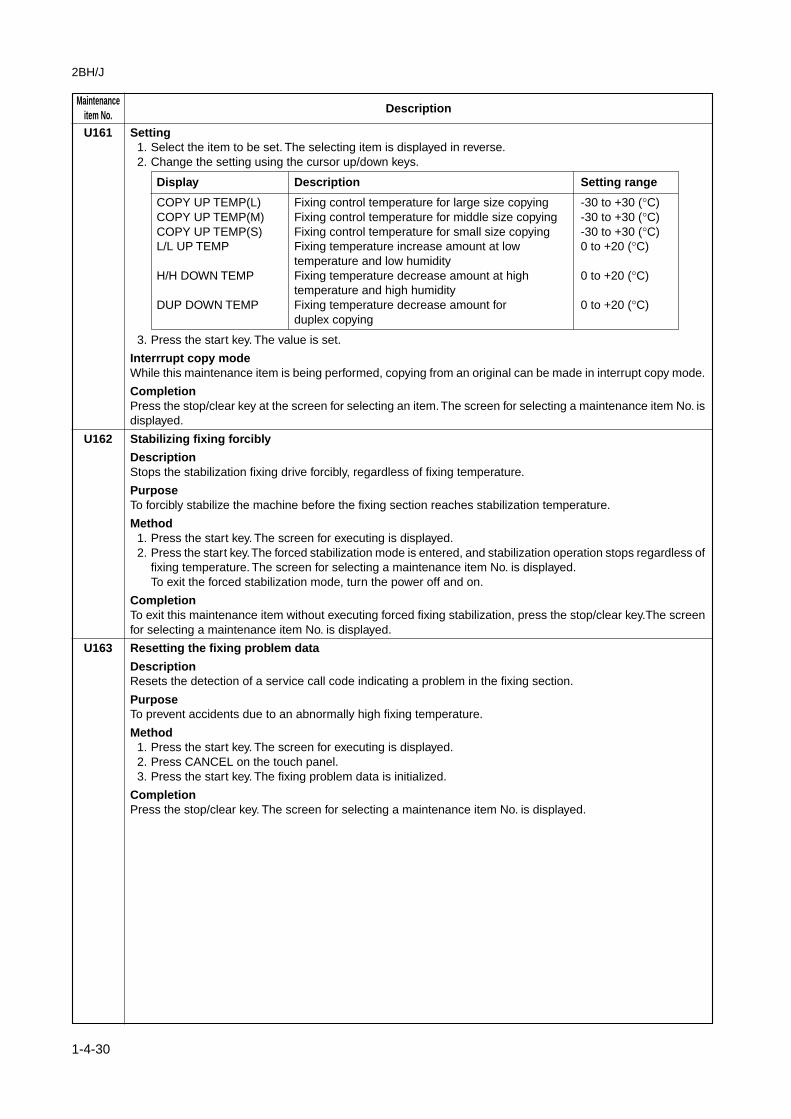
U161 Setting1. Select the item to be set. The selecting item is displayed in reverse.2. Change the setting using the cursor up/down keys.
Display Description Setting range
COPY UP TEMP(L) Fixing control temperature for large size copying -30 to +30 (°C)COPY UP TEMP(M) Fixing control temperature for middle size copying -30 to +30 (°C)COPY UP TEMP(S) Fixing control temperature for small size copying -30 to +30 (°C)L/L UP TEMP Fixing temperature increase amount at low 0 to +20 (°C)
temperature and low humidityH/H DOWN TEMP Fixing temperature decrease amount at high 0 to +20 (°C)
temperature and high humidityDUP DOWN TEMP Fixing temperature decrease amount for 0 to +20 (°C)
duplex copying
3. Press the start key. The value is set.
Interrrupt copy modeWhile this maintenance item is being performed, copying from an original can be made in interrupt copy mode.
CompletionPress the stop/clear key at the screen for selecting an item. The screen for selecting a maintenance item No. isdisplayed.
U162 Stabilizing fixing forcibly
DescriptionStops the stabilization fixing drive forcibly, regardless of fixing temperature.
PurposeTo forcibly stabilize the machine before the fixing section reaches stabilization temperature.
Method1. Press the start key. The screen for executing is displayed.2. Press the start key. The forced stabilization mode is entered, and stabilization operation stops regardless of
fixing temperature. The screen for selecting a maintenance item No. is displayed.To exit the forced stabilization mode, turn the power off and on.
CompletionTo exit this maintenance item without executing forced fixing stabilization, press the stop/clear key.The screenfor selecting a maintenance item No. is displayed.
U163 Resetting the fixing problem data
DescriptionResets the detection of a service call code indicating a problem in the fixing section.
PurposeTo prevent accidents due to an abnormally high fixing temperature.
Method1. Press the start key. The screen for executing is displayed.2. Press CANCEL on the touch panel.3. Press the start key. The fixing problem data is initialized.
CompletionPress the stop/clear key. The screen for selecting a maintenance item No. is displayed.

2BH/J
1-4-31
MaintenanceDescriptionitem No.
U165 Checking/clearing fixing counts
DescriptionDisplays or clears fixing counts.
PurposeTo check fixing counts after replacing the fixing unit.
MethodPress the start key. The fixing counts are displayed.
Clearing1. Press the reset key.2. Press the start key. The count is cleared, and the screen for selecting a maintenance item No. is displayed.
Setting1. Enter a four-digit value using the numeric keys.2. Press the start key. The value is set. The screen for selecting a maintenance item No. is displayed.
CompletionTo exit this maintenance item without changing the current value, press the stop/clear key. The screen forselecting a maintenance item No. is displayed.
U196 Turning the fixing heater on
DescriptionTurns the fixing heater M or S on.
PurposeTo check fixing heaters turning on.
Method1. Press the start key. The screen for selecting an item is displayed.2. Select the heater to be turned on. The selected heater turns on for 3 s and then turns off.
Display Description
MAIN Fixing heater M (FH-M)SUB Fixing heater S (FH-S)
CompletionPress the stop/clear key when fixing motors M and S are off. The screen for selecting the maintenance item No.is displayed.
U199 Checking the fixing temperature
DescriptionDisplays the fixing temperature, the ambient temperature and the absolute humidity.
PurposeTo check the fixing temperature, the ambient temperature and the absolute humidity.
MethodPress the start key. The fixing temperature and ambient temperature are displayed in centigrade (°C) and theabsolute humidity is displayed in percentage (%).
Display Description
FIX TEMP Fixing temperature (°C)SURROUND TEMP Ambient temperature (°C)HUMIDITY Absolute humidity (%)
CompletionPress the stop/clear key. The screen for selecting a maintenance item No. is displayed.

MaintenanceDescriptionitem No.
2BH/J
1-4-32
U200 Turning all LEDs on
DescriptionTurns all the LEDs on the operation panel on.
PurposeTo check if all the LEDs on the operation panel light.
MethodPress the start key. All the LEDs on the operation panel light.Press the stop/clear key or wait for 10 s. The LEDs turns off, and the screen for selecting a maintenance itemNo. is displayed.
U201 Initializing the touch panel
DescriptionAutomatically correct the positions of the X- and Y-axes of the touch panel.
PurposeTo automatically correct the display positions on the touch panel after it is replaced.
Method1. Press the start key. The screen for executing is displayed, and the + key displayed at the upper left of the
touch panel flashes.2. Press on the center of the + key. The + key on lower right flashes.3. Press the center of the flashing +. Initialization of the touch panel is complete, and the screen for selecting
a maintenance item No. is displayed.
CompletionTo exit this maintenance item without initializing, press the stop/clear key. The screen for selecting amaintenance mode No. is displayed.
U202 Setting the KMAS host monitoring system
DescriptionInitializes or operates the KMAS host monitoring system.This is an optional device which is currently supported only by Japanese specification machines, so no settingis necessary.

2BH/J
1-4-33
MaintenanceDescriptionitem No.
U203 Operating DF separately
DescriptionSimulates the original conveying operation separately in the optional DF.
PurposeTo check the DF.
Method1. Press the start key. The screen for selecting an item is displayed.2. Place an original in the DF if running this simulation with paper.3. Select the item to be operated. The selected item is displayed in reverse.
Display Operation
ADF With paper, single-sided originalRADF With paper, double-sided originalADF (NON-P) Without paper, single-sided original (continuous operation)RADF (NON-P) Without paper, double-sided original (continuous operation)
4. Press the start key. The operation starts.5. To stop continuous operation, press the stop/clear key.
CompletionPress the stop/clear key when the operation stops. The screen for selecting a maintenance item No. isdisplayed.
U204 Setting the presence or absence of a key card or key counter
DescriptionSets the presence or absence of the optional key card or key counter.
PurposeTo run this maintenance item if a key card or key counter is installed.
MethodPress the start key. The screen for selecting an item is displayed
Setting1. Select the optional counter to be installed using the cursor up/down keys. The selected counter is displayed
in reverse.
Display Description
KEY-CARD The key card is installedKEY-COUNTER The key counter is installed
2. Press the start key. The setting is set and the screen for selecting a maintenance item No. is displayed.
CompletionTo exit this maintenance item without changing the current setting, press the stop/clear key. The screen forselecting a maintenance item No. is displayed.

MaintenanceDescriptionitem No.
2BH/J
1-4-34
U206 Setting the presence or absence of the coin vender
DescriptionSets the presence or absence of the optional coin vender. Also sets the details for coin vender operation, suchas mode and unit price.This is an optional device which is currently supported only by Japanese specification machines, so no settingis necessary.
U207 Checking the operation panel keys
DescriptionChecks operation of the operation panel keys.
PurposeTo check operation of all the keys and LEDs on the operation panel.
Method1. Press the start key. The screen for executing is displayed.2. "COUNT1" is displayed and the leftmost LED on the operation panel lights.
3. As the keys lined up in the same line as the lit indicator are pressed in the order from the top to the bottom,the figure shown on the touch panel increases in increments of 1. When all the keys in that line are pressedand if there are any LEDs corresponding to the keys in the line on the immediate right, the top LED in thatline will light.
4. When all the keys on the operation panel have been pressed, all the LEDs light for up to 10 seconds.5. When the LEDs go off, press the start key. All the LEDs light for 10 seconds again.
CompletionPress the stop/clear key. The screen for selecting a maintenance item No. is displayed.
U208 Setting the paper size for the large paper deck
DescriptionSets the size of paper used in the optional large paper deck. Note that the setting cannot be changed on inch-specification machines since the paper size for the large paper deck is fixed.
PurposeTo change the setting when the size of paper used in the large paper deck is changed.
MethodPress the start key. The screen for selecting an item is displayed.
Setting1. Select the paper size (A4 or A5). The selected item is displayed in reverse.
Initial setting: A42. Press the start key. The setting is set.
CompletionPress the stop/clear key. The screen for selecting a maintenance item No. is displayed.
U211 Setting DF type
DescrioptionSets the optional DF type (STDF or SRDF). (For 25 cpm copier only)
PurposeTo set DF type when installing.
MethodPress the start key. The screen for selecting an item is displayed.
Setting1. Select DF type. The selected item is displayed in reverse.
Display Description
SADF Single-sided (STDF)SRADF Double-sided (SRDF)
2. Press the start key. The type is set.
CompletionPress the stop/clear key. The screen for selectiong a maintenance item No. is displayed.

2BH/J
1-4-35
MaintenanceDescriptionitem No.
U217 Setting 81/2" × 13" paper
DescriptionTurn on the setting when using 81/2" × 13" paper.
PurposeTo change the setting as needed.
MethodPress the start key. The screen for selscting an item is displayed.
Setting1. Select ON or OFF. The selected item is displayed in reverse.
Display Description
ON 81/2" × 13" paper is used.OFF 81/2" × 13" paper is not used.
2. Press the start key. The value is set. The screen for selecting a maintenance item No. is displayed.
CompletionTo exit this maintenance item without changing the current setting, press the stop/clear key. The screen forselecting a maintenance item No. is displayed.
U237 Setting finisher stack quantity
DescriptionSets the number of sheets of each stack on the main tray and on the intermediate tray in the optional finisher.
PurposeTo change the setting when a stack malfunction has occurred.
Method1. Press the start key. The screen for selecting an item is displayed.2. Select the item to be set. The selected item is displayed in reverse.
Display Description
MAIN TRAY Number of sheets of stack on the main trayMIDDLE TRAY Number of sheets of stack on the intermediate tray for sort
copying or staple copying
Setting the number of sheets of stack on the main tray1. Change the setting using the cursor up/down keys.
Setting Description
0 3000-sheet finisher: 1500 sheets, built-in finisher: 250 sheets1 3000-sheet finisher: 3000 sheets, built-in finisher: 500 sheets
Initial setting: 12. Press the start key. The setting is set.
Setting the number of sheets of stack on the intermediate tray for sort copying or staple copying1. Change the setting using the cursor up/down keys.
Setting Description
0 For sort copying: 30 sheets, for staple copying: 50 sheets1 For sort copying: 30 sheets, for staple copying: 30 sheets
Initial setting: 12. Press the start key. The setting is set.
CompletionPress the stop/clear key. The screen for selectiong a maintenance item No. is displayed.

MaintenanceDescriptionitem No.
2BH/J
1-4-36
U243 Checking the operation of the DF motors, solenoids and clutch
DescriptionTurns the motors, solenoids or clutch in the optional DF on.
PurposeTo check the operation of the DF motors, solenoids and clutch .
Method1. Press the start key. The screen for selecting an item is displayed.2. Select the item to be operated. The selected item is displayed in reverse and the operation starts.
Display Motors, solenoids and clutch Operation In operation
F MOT Original feed motor (OFM) In operationC MOT Original paper conveying motor (OCM) On for 0.5 sFD CL Original feed clutch (OFCL) On for 0.5 sEJ SL Eject feedshift solenoid (EFSSOL) On for 0.5 sRJ SL Switchback feedshift solenoid (SBFSSOL) On for 0.5 sFD SL Original feed solenoid (OFSOL) On and offRP SL Switchback pressure solenoid (SBPSOL) On and off
3. To turn each motor off, press the stop/clear key.
CompletionPress the stop/clear key when operation stops. The screen for selecting a maintenance item No. is displayed.
U244 Checking the DF switches
DescriptionDisplays the status of the respective switches in the optional DF.
PurposeTo check if respective switches in the optional DF operate correctly.
Start1. Press the start key. The screen for selecting an item is displayed.2. Select the type of switches (SW or VR) to be checked. The screen for executing each item is displayed.
Display Type of switches
SW On/off switchesVR Volume switch
Method for the on/off switches1. Turn the respective switches on and off manually to check the status.
If the on-status of a switch is detected, the corresponding switch is displayed in reverse.
Display Switches
SET Original set switch (OSSW)FEED Original feed switch (OFSW)REV Original switchback switch (OSBSW)TMG DF timing switch (DFTSW)SZ A Original size length switch (OSLSW)
2. To return to the screen for selecting an item, press the stop/clear key.
2BH/J
1-4-37
MaintenanceDescriptionitem No.
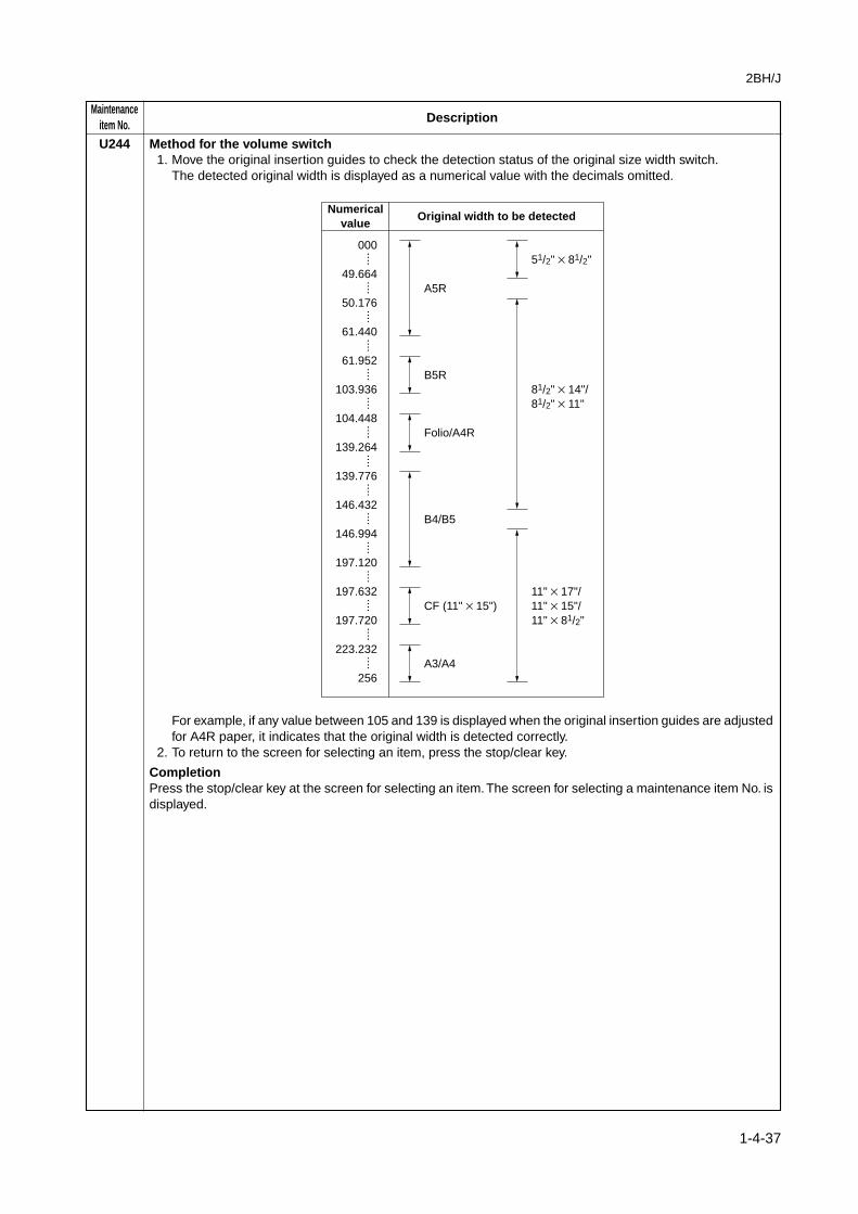
U244 Method for the volume switch1. Move the original insertion guides to check the detection status of the original size width switch.
The detected original width is displayed as a numerical value with the decimals omitted.
Numericalvalue
A5R
B5R
Folio/A4R
B4/B5
CF (11" × 15")
A3/A4
Original width to be detected
51/2" × 81/2"
81/2" × 14"/81/2" × 11"
11" × 17"/11" × 15"/11" × 81/2"
000
49.664
50.176
61.440
61.952
103.936
104.448
139.264
139.776
146.432
146.994
197.120
197.632
197.720
223.232
256
····
····
····
····
····
····
····
····
····
····
····
····
····
····
····
For example, if any value between 105 and 139 is displayed when the original insertion guides are adjustedfor A4R paper, it indicates that the original width is detected correctly.
2. To return to the screen for selecting an item, press the stop/clear key.
CompletionPress the stop/clear key at the screen for selecting an item. The screen for selecting a maintenance item No. isdisplayed.

MaintenanceDescriptionitem No.
2BH/J
1-4-38
U245 Checking messages
DescriptionDisplays a list of messages on the touch panel of the operation panel.
PurposeTo check the messages to be displayed.
Method1. Press the start key.2. Select the item to be displayed.3. Change the screen using the cursor up/down keys to display each message one at a time.
When a message number is entered with the numeric keys and then the start key is pressed, the messagecorresponding the specified number is displayed.
CompletionPress the stop/clear key. The screen for selecting a maintenance item No. is displayed.
U246 Setting the finisher
DescriptionAdjusts the amount of slack in the paper for the optional finisher in punch mode when it is attached. Also adjuststhe booklet stapling position for each paper size when the optional booklet stitcher is attached.
Purpose• Adjustment of the amount of slack in the paper in punch modeAdjusts the amount of slack in the paper while in the punch section if, in punch mode, paper jams or is Z-foldedfrequently due to too much slack in the paper, or, the position of punch holes varies due to too little slack in thepaper.• Booklet stapling position adjustmentAdjusts the booklet stapling position in the stitching mode if the position is not proper.
Start1. Press the start key. The screen for selecting an item is displayed.2. Select the item to be set and press the start key. The screen for executing each item is displayed.
Display Description
3000 FINISHER Adjustment of the amount of slack in the paper in punch modeSADDLE FINISHER Booklet stapling position adjustment
Setting the amount of slack in the paper1. Change the setting using the cursor up/down keys.
Description Setting range Initial setting
Amount of slack in the paper -15 to +15 0
If the position of punch holes varies, increase the setting to make the amount of slack larger.If paper jams or is Z-folded frequently, decrease the setting to make the amount of slack smaller.
2. Press the start key. The value is set.3. To return to the screen for selecting an item, press the stop/clear key.
Setting the booklet stapling position1. Select the size to be set. The selected item is displayed in reverse.2. Change the setting using the cursor up/down keys.
Display Description Setting range Initial settingChange in valueper step
A4R Adjustment of booklet stapling –125 to +125 0 0.25 mmposition for A4R size
B4R Adjustment of booklet stapling –125 to +125 0 0.25 mmposition for B4R size
A3R/LDR Adjustment of booklet stapling –125 to +125 0 0.25 mmposition for A3R/LDR size

2BH/J
1-4-39
MaintenanceDescriptionitem No.
U246
Left stapling Right stapling Adjustment method
Proper
Decrease the preset value.
Increase the preset value.
Upper side is longer. Lower side is longer.
Lower side is longer. Upper side is longer.
3. Press the start key. The value is set.4. To return to the screen for selecting an item, press the stop/clear key.
CompletionPress the stop/clear key at the screen for selecting an item. The screen for selecting a maintenance item No. isdisplayed.
U247 Checking the operation of large paper deck and paper feed desk
DescriptionTurns on motors and clutches of optional large paper deck or paper feed desk.
PurposeTo check the operation of motors and clutches of paper feed device.
Start1. Press the start key. The screen for selecting an item is displayed.2. Select the device to be checked.
Display Paper feed device
3000 DECK Large paer deck500 × 2 DECK Paper feed desk
Method1. Select the item to be operated. The selected item is displayed in reverse and operation starts.
Large paper deck
Display Motors and clutches Operation
LCF MOT Conveying motor (CM) On for 5 sB CL Conveying clutch (CCL) On for 1 sPCL1 Paper feed clutch 1(PFCL1) On for 1 sPCL2 Paper feed clutch 2(PFCL2) On for 1 s
Paper feed desk
Display Motors and clutches Operation
DESK MOT Desk Drive motor (DDM) On for 5 sFEED CL Desk feed clutch (DFCL) On for 1 sUPP CL Desk upper paper feed clutch (DPFCL-U) On for 1 sLOW CL Desk lower paper feed clutch (DPFCL-L) On for 1 s
MaintenanceDescriptionitem No.
2BH/J
1-4-40
U247 2. To return to the screen for selecting an item, press the stop/clear key.
CompletionPress the stop/clear key at the screen for selecting an item. The screen for selecting a maintenance item No. isdisplayed.
U249 Checking the paper ejection to optional devices
DescriptionEjects paper to an optional mailbox or job separator, or to the ejection slot at the machine left.
PurposeTo check paper conveying operation to optional paper eject devices or the ejection slot at the machine left.
Method1. Press the start key. The screen for selecting an item is displayed.2. Select the paper eject location.
Display Paper eject device
MAIL BOX MailboxJOB SEPARATOR Job separatorLEFT BIN OUTPUT Ejection slot at the machine left (finisher not installed)
3. When selecting the mailbox, specify the mail tray number (1 to 7) to which paper is to be ejected by usingthe cursor up/down keys. If 0 is selected, paper is ejected to the mail trays in ascending order from mail tray1 to mail tray 7 repeatedly.
Interrupt copy modeWhile this maintenance item is being performed, copying from an original can be made in interrupt copy mode.
CompletionPress the stop/clear key. The screen for selecting a maintenance item No. is displayed.
U250 Setting the maintenance cycle
DescriptionDisplays and changes the maintenance cycle.
PurposeTo check and change the maintenance cycle.
MethodPress the start key. The current setting is displayed as follows:
Setting1. Change the setting using the numeric keys.
Description Setting range Initial setting
Maintenance cycle 0 to 600000 500000 (35 cpm) 400000 (25 cpm)
2. Press the start key. The value is set, and the screen for selecting a maintenance item No. is displayed.
CompletionTo exit this maintenance item without changing the current setting, press the stop/clear key. The screen forselecting a maintenance item No. is displayed.

2BH/J
1-4-41
MaintenanceDescriptionitem No.
U251 Checking/clearing the maintenance count
DescriptionDisplays, clears and changes the maintenance count.
PurposeTo check the maintenance count. Also to clear the count during maintenance service.
MethodPress the start key. The maintenance count is displayed.
Clearing1. Press the reset key.2. Press the start key. The count is cleared, and the screen for selecting a maintenance item No. is displayed.
Setting1. Enter a six-digit count using the numeric keys.2. Press the start key. The count is set, and the screen for selecting a maintenance item No. is displayed.
CompletionTo exit this maintenance item without changing the count, press the stop/clear key. The screen for selecting amaintenance item No. is displayed.
U252 Setting the destination
DescriptionSwitches the operations and screens of the machine according to the destination.
PurposeTo be executed after replacing the backup RAM on the main PCB or initializing the backup RAM by runningmaintenance item U020, in order to return the setting to the value before replacement or initialization.
MethodPress the start key. The screen for selecting an item is displayed.
Setting1. Select the destination. The selected item is displayed in reverse.
Display Description
JAPAN METRIC Metric (Japan) specificationsINCH Inch (North America) specificationsEUROPE METRIC Metric (Europe) specificationsASIA PACIFIC Metric (Asia Pacific) specifications
2. Press the start key. The setting is set, and the machine automatically returns to the same status as whenthe power is turned on.
CompletionTo exit this maintenance item without changing the current count, press the stop/clear key. The screen forselecting a maintenance item No. is displayed.
SupplementThe specified initial settings are provided according to the destinations in the maintenance items below. Tochange the initial settings in those items, be sure to run maintenance item U021 after changing the destination.• Initial setting according to the destinations
Maintenance Title Japan Inch Europe Metric,item No. Asia Pacific
253 Switching between double and single counts Single Double Double255 Setting auto clear time 120 s 90 s 90 s
MaintenanceDescriptionitem No.
2BH/J
1-4-42
U253 Switching between double and single counts
DescriptionSwitches the count system for the total counter and other counters.
PurposeAccording to user (copy service provider) request, select if A3/11" × 17" paper is to be counted as one sheet(single count) or two sheets (double count).
MethodPress the start key. The screen for selecting an item is displayed.
Setting1. Select double or single count. The selected item is displayed in reverse.
Display Description
DOUBLE COUNT Double count for A3/11" × 17" paper onlySINGLE COUNT Single count for all size paper
Initial setting: DOUBLE COUNT2. Press the start key. The setting is set, and the screen for selecting a maintenance item No. is displayed.
CompletionTo exit this maintenance item without changing the current setting, press the stop/clear key. The screen forselecting a maintenance item No. is displayed.
U254 Turning auto start function on/off
DescriptionSelects if the auto start function is turned on.
PurposeNormally no change is necessary. If incorrect operation occurs, turn the function off: this may solve theproblem.
MethodPress the start key. The screen for selecting an item is displayed.
Setting1. Select either ON or OFF. The selected item is displayed in reverse.
Display Description
ON Auto start function onOFF Auto start function off
Initial setting: ON2. Press the start key. The setting is set, and the screen for selecting a maintenance item No. is displayed.
CompletionTo exit this maintenance item without changing the current setting, press the stop/clear key. The screen forselecting a maintenance item No. is displayed.

2BH/J
1-4-43
MaintenanceDescriptionitem No.
U255 Setting auto clear time
DescriptionSets the time to return to initial settings after copying is complete.
PurposeTo be set according to frequency of use. Set to a comparatively long time for continuous copying at the samesettings, and a comparatively short time for frequent copying at various settings.
MethodPress the start key. The current setting is displayed.
Setting1. Change the setting using the cursor up/down keys.
Description Setting range Initial setting
Auto clear time 0 to 270 90
The setting can be changed by 30 s per step.When set to 0, the auto clear function is cancelled.
2. Press the start key. The value is set, and the screen for selecting a maintenance item No. is displayed.
CompletionTo exit this maintenance item without changing the current setting, press the stop/clear key. The screen forselecting a maintenance item No. is displayed.
U256 Turning auto preheat/energy saver function on/off
DescriptionSelects if the auto preheat/energy saver function is turned on. When set to ON, the time to enter preheat/energy saver mode can be changed in copy management mode.
PurposeAccording to user request, to set the preheat time to save energy, or enable copying promptly without therecovery time from preheat mode.
MethodPress the start key. The screen for selecting an item is displayed.
Setting1. Select ON or OFF. The selected item is displayed in reverse.
Display Description
ON Auto preheat/energy saver function onOFF Auto preheat/energy saver function off
Initial setting: ON2. Press the start key. The setting is set, and the screen for selecting a maintenance item No. is displayed.
When the setting is changed from OFF to ON, the auto preheat time is set to the initial setting of 15minutes.
CompletionTo exit this maintenance item without changing the current setting, press the stop/clear key. The screen forselecting a maintenance item No. is displayed.

MaintenanceDescriptionitem No.
2BH/J
1-4-44
U258 Switching copy operation at toner empty detection
DescriptionSelects if continuous copying is enabled after toner empty is detected, and sets the number of copies that canbe made after the detection.
MethodPress the start key. The current setting is displayed.
Setting1. Select single or continuous copying. The selected item is displayed in reverse.
Display Description
SINGLE Enables only single copying.CONTINUE Enables single and continuous copying.
Initial setting: SINGLE2. Set the number of copies that can be made using the cursor up/down keys.
Description Setting range Initial setting
Number of copies after toner empty detection 0 to 200 (copies) 0
The setting can be changed by 5 copies per step.When set to 0, the number of copies is not limited regardless of the setting for single or continuous copying.
3. Press the start key. The setting is set, and the screen for selecting a maintenance item No. is displayed.
CompletionTo exit this maintenance item without changing the current setting, press the stop/clear key. The screen forselecting a maintenance item No. is displayed.
U260 Changing the copy count timing
DescriptionChanges the copy count timing for the total counter and other counters.
PurposeTo be set according to user (copy service provider) request.If a paper jam occurs frequently in the finisher when the number of copies is counted at the time of paperejection, copies are provided without copy counts. The copy service provider cannot charge for such copying.To prevent this, the copy timing should be made earlier.If a paper jam occurs frequently in the paper conveying or fixing sections when the number of copies is countedbefore the paper reaches those sections, copying is charged without a copy being made. To prevent this, thecopy timing should be made later.
MethodPress the start key. The screen for selecting an item is displayed.
Setting1. Select the copy count timing . The selected item is displayed in reverse.
Display Description
FEED When secondary paper feed startsEJECT When the paper is ejected
Initial setting: EJECT2. Press the start key. The setting is set, and the screen for selecting a maintenance item No. is displayed.
CompletionTo exit this maintenance item without changing the current setting, press the stop/clear key. The screen forselecting a maintenance item No. is displayed.

2BH/J
1-4-45
MaintenanceDescriptionitem No.
U265 Setting OEM purchaser code
DescriptionSets the OEM purchaser code.
PurposeSets the code when replacing the main PCB and the like.
MethodPress the start key.
Setting1. Use the numeric keys or cursor up/down keys to adjust the preset value.2. Press the start key. The count is set , and the screen for selecting a maintenance item is displayed.
CompletionTo exit this maintenance item without changing the current setting, press the stop/clear key. The screen forselecting a maintenance item is displayed.
U330 Setting the number of sheets to enter stacking mode during sort operation
DescriptionWhen sort copying is set to perform automatically in the output form setting of the user simulation, sets thenumber of sheets at which the eject location is switched to the optional finisher (only when the finisher isinstalled).
PurposeTo be set as required according to the number of copies the user makes.
MethodPress the start key. The current setting is displayed.
Setting1. Set the number of sheets (o to 250) using the numeric keys or cursor up/down keys.2. Press the start key. The setting is set. The screen for selecting a maintenance item No. is displayed.
CompletionTo exit this maintenance item without changing the current setting, press the stop/clear key. The screen forselecting a maintenance item No. is displayed.

MaintenanceDescriptionitem No.
2BH/J
1-4-46
U332 Setting the size conversion factor
DescriptionSets the factor for converting each paper size into A4/11" × 81/2". The black ratio is converted for the A4/11" ×81/2" size using the factor set in this maintenance item. Values set are displayed in the user simulation.
PurposeTo set the factor to convert the black ratio of each paper size for A4/11" × 81/2" size.
Method1. Press the start key. The screen for selecting an item is displayed.2. Select the paper size.3. Change the setting using the cursor up/down keys.
The size conversion factor can be set separately for the copier mode (COPY), the printer mode (PRI) andthe fax mode (FAX) at the screen for setting the size conversion factor.Metric models
Display Description Setting Initial setting
COPY PRI FAX
A3 Size conversion factor for A3 0.0 to 3.0 2.0 2.0 2.0B4 Size conversion factor for B4 0.0 to 3.0 1.5 1.5 1.5A4 Size conversion factor for A4 0.0 to 3.0 1.0 1.0 1.0B5 Size conversion factor for B5 0.0 to 3.0 0.7 0.7 0.7A5 Size conversion factor for A5 0.0 to 3.0 0.5 0.5 0.5B6 Size conversion factor for B6 0.0 to 3.0 0.4 0.4 0.4A6 Size conversion factor for A6 0.0 to 3.0 0.3 0.3 0.3FOLIO Size conversion factor for folio 0.0 to 3.0 0.3 0.3 0.3OTHER Size conversion factor for non-standard sizes 0.0 to 3.0 1.0 1.0 1.0
Inch models
Display Description Setting Initial setting
COPY PRI FAX
11 × 17 Size conversion factor for 11" × 17" 0.0 to 3.0 2.0 2.0 2.08.5 × 14 Size conversion factor for 8.5" × 14" 0.0 to 3.0 1.5 1.5 1.58.5 × 11 Size conversion factor for 8.5" × 11" 0.0 to 3.0 1.0 1.0 1.05.5 × 8.5 Size conversion factor for 5.5" × 8.5" 0.0 to 3.0 0.7 0.7 0.7OTHER Size conversion factor for non-standard sizes 0.0 to 3.0 0.5 0.5 0.5
4. Press the start key. The setting is set.
CompletionTo exit this maintenance item without changing the current setting, press the stop/clear key. The screen forselecting a maintenance item is displayed.
U341 Specific paper feed location setting for printing function
DescriptionSets a paper feed location specified for printer output (only if a printer kit is installed).
PurposeTo use a paper feed location only for printer output.
Method1. Press the start key. The screen for selecting an item is displayed.2. Select the paper feed location for the printer. The selected item is displayed in reverse.
Display Description
FIRST Upper drawerSECOND Lower drawerTHIRD Optional upper drawerFOURTH Optional lower drawerLCF Optional large paper deck
3. Press the start key. The setting is set.
CompletionPress the stop/clear key. The screen for selecting a maintenance item is displayed.

2BH/J
1-4-47
MaintenanceDescriptionitem No.
U342 Setting the ejection restriction
DescriptionSets or cancels the restriction on the number of sheets to be ejected continuously when the internal eject trayis selected as the eject location.
PurposeAccording to user request, sets or cancels restriction on the number of sheets.
Method1. Press the start key. The screen for selecting an item is displayed.2. Select ON or OFF.
Display Description
ON Sets restriction on the number of sheetsOFF Cancels restriction on the number of sheets
Details of restriction (number of sheets to be ejected continuously after the start key is pressed)
Condition Number of sheets
When no optional ejection device is installed 250When the job separator or duplex unit is installed 150When the finisher is installed 100
3. Press the start key. The setting is set.
CompletionPress the stop/clear key. The screen for selectiong a maintenance item No. is displayed.
U343 Switching between duplex/simplex copy mode
DescriptionSwitches the initial setting between duplex and simplex copy.
PurposeTo be set according to frequency of use: set to the more frequently used mode.
MethodPress the start key. The screen for selecting an item is displayed.
Setting1. Select ON or OFF. The selected item is displayed in reverse.
Display Description
ON Duplex copyOFF Simplex copy
Initial setting: OFF2. Press the start key. The setting is set, and the screen for selecting a maintenance item No. is displayed.
CompletionTo exit this maintenance item without changing the current setting, press the stop/clear key. The screen forselecting a maintenance item No. is displayed.

MaintenanceDescriptionitem No.
2BH/J
1-4-48
U344 Setting preheat/energy saver mode
DescriptionChanges the control for preheat/energy saver mode.
PurposeAccording to user request, selects which has priority, the recovery time from preheat or energy saver.
MethodPress the start key. The screen for selecting an item is displayed.
Setting1. Select control mode. The selected item is displayed in reverse.
Display Control in preheat mode
INSTANT READY Without decreasing the fixing control temperature, the display on theoperation panel is turned off.
ENERGY STAR The fixing control temperature is set at 130°C.The copier is forcibly stabilized 30 s after exiting preheat/energy saver mode.
E 2000 The fixing control temperature is decreased by 70°C.
Initial setting: E 20002. Press the start key. The setting is set, and the screen for selecting a maintenance item No. is displayed.
CompletionTo exit this maintenance item without changing the current setting, press the stop/clear key. The screen forselecting a maintenance item No. is displayed.
U345 Setting the value for maintenance due indication
DescriptionSets when to display a message notifying that the time for maintenance is about to be reached, by setting thenumber of copies that can be made before the current maintenance cycle ends.When the difference between the number of copies of the maintenance cycle and that of the maintenancecount reaches the set value, the message is displayed.This maintenance mode is effective for only Japanese specification.
U402 Adjusting margins of image printing
AdjustmentSee page 1-6-13.
U403 Adjusting margins for scanning an original on the contact glass
AdjustmentSee page 1-6-31.
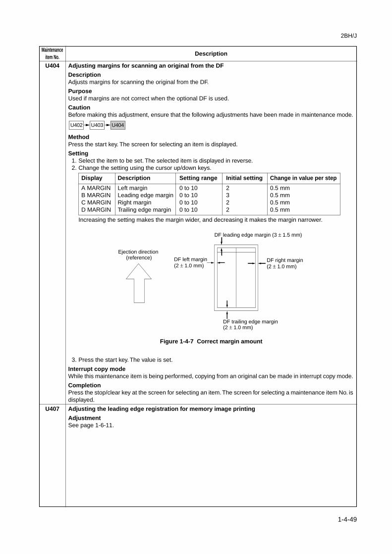
2BH/J
1-4-49
MaintenanceDescriptionitem No.
U404 Adjusting margins for scanning an original from the DF
DescriptionAdjusts margins for scanning the original from the DF.
PurposeUsed if margins are not correct when the optional DF is used.
CautionBefore making this adjustment, ensure that the following adjustments have been made in maintenance mode.
U402 U403 U404
MethodPress the start key. The screen for selecting an item is displayed.
Setting1. Select the item to be set. The selected item is displayed in reverse.2. Change the setting using the cursor up/down keys.
Display Description Setting range Initial setting Change in value per step
A MARGIN Left margin 0 to 10 2 0.5 mmB MARGIN Leading edge margin 0 to 10 3 0.5 mmC MARGIN Right margin 0 to 10 2 0.5 mmD MARGIN Trailing edge margin 0 to 10 2 0.5 mm
Increasing the setting makes the margin wider, and decreasing it makes the margin narrower.
DF leading edge margin (3 ± 1.5 mm)
Ejection direction (reference)
DF trailing edge margin (2 ± 1.0 mm)
DF left margin (2 ± 1.0 mm)
DF right margin (2 ± 1.0 mm)
Figure 1-4-7 Correct margin amount
3. Press the start key. The value is set.
Interrupt copy modeWhile this maintenance item is being performed, copying from an original can be made in interrupt copy mode.
CompletionPress the stop/clear key at the screen for selecting an item. The screen for selecting a maintenance item No. isdisplayed.
U407 Adjusting the leading edge registration for memory image printing
AdjustmentSee page 1-6-11.

MaintenanceDescriptionitem No.
2BH/J
1-4-50
U901 Checking/clearing copy counts by paper feed locations
DescriptionDisplays or clears copy counts by paper feed locations.
PurposeTo check the time to replace consumable parts. Also to clear the counts after replacing the consumable parts.
Method1. Press the start key. The counts by paper feed locations are displayed.2. Change the screen using the cursor up/down keys.
Display Paper feed locations
BYPASS Bypass trayFIRST Upper drawerSECOND Lower drawerTHIRD Optional drawer 1FORTH Optional drawer 2LCF Optional large paper deckDUPLEX Optional duplex unit
When an optional paper feed device is not installed, the corresponding count is not displayed.
Clearing1. Select the count to be cleared. The selected item is displayed in reverse.
To clear the counts for all paper feed locations, press ALL on the touch panel.2. Press the start key. The count is cleared, and the screen for selecting a maintenance item No. is displayed.
CompletionTo exit this maintenance item without changing the current setting, press the stop/clear key. The screen forselecting a maintenance item No. is displayed.
U902 Checking/clearing finisher punch count
DescriptionSets the punch limit and displays and clears the punch-hole scrap count when the optional finisher is attached.
PurposeSets the punch limit to notify the user of the time to collect punch-hole scrap. Also, used to manually clear thepunch-hole scrap count if a message requiring collection of punch-hole scrap is shown on the touch panel aftercollection. If punch-hole scrap is collected with the copier power turned off, the punch-hole scrap count is notcleared and consequently this problem occurs.
Start1. Press the start key. The screen for selecting in item is displayed.2. Select the item. The selecting an item is displayed in reverse.
Display Description Setting range Initial setting
PUNCH LIMIT Punch limit 0 to 999000 75000(maximum number of punching times)
PUNCH COUNT Punch-hole scrap count – –(current number of punching times)
Setting the punch limit1. Change the setting using the numeric keys.2. Press the start key. The value is set.
Clearing1. Press the reset key.2. Press the start key. The count is cleared, and the screen for selecting a maintenance item No. is displayed.
CompletionTo exit this maintenance item without changing the current setting, press the stop/clear key. The screen forselecting a maintenance item No. is displayed.

2BH/J
1-4-51
MaintenanceDescriptionitem No.
U903 Checking/clearing the paper jam counts
DescriptionDisplays or clears the jam counts by jam locations.
PurposeTo check the paper jam status. Also to clear the jam counts after replacing consumable parts.
Method1. Press the start key. The jam count is displayed by jam codes.2. Change the screen using the * or # keys.
Clearing1. Press the reset key. Jam counts cannot be cleared individually.2. Press the start key. The count is cleared, and the screen for selecting a maintenance item No. is displayed.
CompletionTo exit this maintenance item without changing the current setting, press the stop/clear key. The screen forselecting a maintenance item No. is displayed.
U904 Checking/clearing the service call counts
DescriptionDisplays or clears the service call code counts by types.
PurposeTo check the service call code status by types. Also to clear the service call code counts after replacingconsumable parts.
Method1. Press the start key. The service call count is displayed by service call codes.2. Change the screen using the * or # keys.
Clearing1. Select the count to be cleared. The selected item is displayed in reverse. To clear all counts, press the reset
key.2. Press the start key. The count is cleared. When all counts are cleared, the screen for selecting a
maintenance item No. is displayed.
CompletionTo exit this maintenance item without changing the current setting, press the stop/clear key. The screen forselecting a maintenance item No. is displayed.

MaintenanceDescriptionitem No.
2BH/J
1-4-52
U905 Checking/clearing counts by optional devices
DescriptionDisplays or clears the counts of the optional DF or finisher.
PurposeTo check the use of the DF and finisher. Also to clear the counts after replacing consumable parts.
Method1. Press the start key. The screen for selecting an item is displayed.2. Select the device, the count of which is to be checked and press the start key. The count of the selected
device is displayed.• DF
Display Description
CHANGE Original replacement countADF No. of single-sided originals that has passed through the DF in ADF modeRADF No. of double-sided originals that has passed through the DF in RADF mode
• Finisher (SORTER)
Display Description
CP CNT No. of copies that has passedSTAPLE Frequency the stapler has been activatedSTACK Frequency the stacker has been activated
Clearing1. Select the item to be cleared. The selected item is displayed in reverse.2. Press the start key. The count is cleared.3. To return to the screen for selecting an item, press the stop/clear key.
CompletionPress the stop/clear key at the screen for selecting an item. The screen for selecting a maintenance item No. isdisplayed.
U906 Resetting partial operation control
DescriptionResets the service call code for partial operation control.
PurposeTo be reset after partial operation is performed due to problems in the drawers or other sections, and therelated parts are serviced.
Method1. Press the start key.2. Press EXECUTE on the touch panel.3. Press the start key to reset partial operation control. The maintenance mode is exited, and the machine
returns to the same status as when the main switch is turned on.
2BH/J
1-4-53
MaintenanceDescriptionitem No.
U908 Changing the total counter value
DescriptionDisplays, clears and changes the total counter value.
PurposeTo check the total counter value.
MethodPress the start key. The total counter value is displayed.
Clearing1. Press the reset key.2. Press the start key. The value is cleared. The screen for selecting a maintenance item No. is displayed.
Setting1. Enter a six-digit value using the numeric keys.2. Press the start key. The value is set. The screen for selecting a maintenance item No. is displayed.
CompletionTo exit this maintenance item without changing the current total counter value, press the stop/clear key. Thescreen for selecting a maintenance item No. is displayed.
U910 Clearing the black ratio data
DescriptionClears the accumulated black ratio data for A4 sheets.
PurposeTo clear data as required at times such as during maintenance service.
Method1. Press the start key.2. Press CANCEL on the touch panel.3. Press the start key. The accumulated black ratio data is cleared, and the screen for selecting a
maintenance item is displayed.
CompletionTo exit this maintenance item without changing the current setting, press the stop/clear key. The screen forselecting a maintenance item is displayed.
U911 Checking/clearing copy counts by paper sizes
DescriptionDisplays and clears the paper feed counts by paper sizes.
PurposeTo check or clear the counts after replacing consumable parts.
MethodPress the start key. The screen for the paper feed counts by paper size is displayed.
Clearing1. Select the paper size. The selected item is displayed in reverse.
To clear all counts, press the reset key.2. Press the start key. The count is cleared.
When clearing all counts, the screen for selecting a maintenance item is displayed.
CompletionTo exit this maintenance item without changing the count, press the stop/clear key. The screen for selecting amaintenance item is displayed.

MaintenanceDescriptionitem No.
2BH/J
1-4-54
U990 Checking/clearing the time for the exposure lamp to light
DescriptionDisplays, clears or changes the accumulated time for the exposure lamp to light.
PurposeTo check duration of use of the exposure lamp. Also to clear the accumulated time for the lamp afterreplacement.
MethodPress the start key. The accumulated time of illumination for the exposure lamp is displayed in minutes.
Clearing1. Press the reset key.2. Press the start key. The accumulated time is cleared, and the screen for selecting a maintenance item No.
is displayed.
Setting1. Enter a six-digit accumulated time using the numeric keys.2. Press the start key. The time is set, and the screen for selecting a maintenance item No. is displayed.
CompletionTo exit this maintenance item without changing the accumulated time, press the stop/clear key. The screen forselecting a maintenance item No. is displayed.
U991 Checking/clearing the scanner count
DescriptionDisplays or clears the scanner operation count.
PurposeTo check the status of use of the scanner.
MethodPress the start key. The screen for selecting an item is displayed.
Display Description
TOTAL SCAN COUNT Counts of scanner operationNT SCAN COUNT Counts of network scanner operation
Clearing1. Select the item to be cleared.2. Press the reset key.3. Press the start key. The count is cleared. The screen for selecting a maintenance item No. is displayed.
Setting1. Select the item to be changed.2. Enter a six-digit count using the numeric key.3. Press the start key. The value is set. The screen for selecting a maintenance item No. is displayed.
CompletionTo exit this maintenance item without changing the current setting, press the stop/clear key. The screen forselecting a maintenance item No. is displayed.

2BH/J
1-4-55
MaintenanceDescriptionitem No.
U992 Checking or clearing the printer/fax count
DescriptionDisplays, clears or changes the print count of the printer or fax when the optional printer board or fax unit isinstalled.
PurposeTo check the frequency of use of the printer or fax.
MethodPress the start key. The screen for selecting an item is displayed.
Display Description
PRINTER COUNT Print count of the printerFAX COUNT Print count of the fax
Clearing1. Select the count to be cleared.2. Press the reset key.3. Press the start key. The count is cleared. The screen for selecting a maintenance item No. is displayed.
Setting1. Select the item to be changed.2. Enter a six-digit count using the numeric keys.
To clear the counts for both printer and fax, press the reset key.3. Press the start key. The value is set.
CompletionPress the stop/clear key. The screen for selecting a maintenance item No. is displayed.

MaintenanceDescriptionitem No.
2BH/J
1-4-56
U993 Outputting a VTC-PG pattern
DescriptionSelects and outputs a VTC-PG pattern created in the copier.
PurposeWhen performing respective image printing adjustments, used to check the machine status apart from that ofthe scanner with a non-scanned output VTC-PG pattern.
Method1. Press the start key. The screen for selecting an item is displayed.2. Select the VTC-PG pattern to be output.
Display PG pattern to be output Purpose
• Center line adjustment
• Lateral squareness adjustment• Magnification adjustment
PG1
PG2
PG3
3. Press the interrupt key. The copy mode screen is displayed.4. Press the start key. A VTC-PG pattern is output.
CompletionPress the stop/clear key at the screen for selecting an item. The screen for selecting a maintenance item No. isdisplayed.