Kirloskar “KOSN Series” Centrifugal Submersible Pump€¦ · Kirloskar “KOSN Series”...
11
Kirloskar “KOSN Series” Centrifugal Submersible Pump A Kirloskar Group Company KIRLOSKAR BROTHERS LIMITED INSTALLATION, OPERATION & MAINTENANCE MANUAL KOSN Series CM - 9862 WORKS : Ujjain Road, Dewas - 455 001 (M.P.) Phone : +91 7272 227401/2/5/9 Fax : +91 7272 228747 Toll Free No. 1800 103 4443 CORPORATE OFFICE : “YAMUNA”, Survey No. 98 (3-7), Baner, Pune 411 045 (India) Phone : +91 20 27214444 E-mail : [email protected] Visit us at : www.kirloskarpumps.com REGISTERED OFFICE : Udyog Bhavan, Tilak Road, Pune - 411 002 (India) Tel. : +91 20 24444444 Fax : +91 20 24444198 E-mail : [email protected] KIRLOSKAR BROTHERS LIMITED A Kirloskar Group Company A View of KBL Dewas Manufacturing Plant 06019860
Transcript of Kirloskar “KOSN Series” Centrifugal Submersible Pump€¦ · Kirloskar “KOSN Series”...

Kirloskar “KOSN Series”Centrifugal Submersible Pump
A Kirloskar Group CompanyKIRLOSKAR BROTHERS LIMITED
INSTALLATION, OPERATION & MAINTENANCE MANUAL
KOSN Series
CM - 9862
WORKS :Ujjain Road, Dewas - 455 001 (M.P.) Phone : +91 7272 227401/2/5/9 Fax : +91 7272 228747 Toll Free No. 1800 103 4443
CORPORATE OFFICE :“YAMUNA”, Survey No. 98 (3-7), Baner, Pune 411 045 (India)Phone : +91 20 27214444 E-mail : [email protected] Visit us at : www.kirloskarpumps.com
REGISTERED OFFICE :Udyog Bhavan, Tilak Road, Pune - 411 002 (India)Tel. : +91 20 24444444 Fax : +91 20 24444198E-mail : [email protected]
KIRLOSKAR BROTHERS LIMITEDA Kirloskar Group Company
A View of KBL Dewas Manufacturing Plant
06019860

FOR PROMPT SERVICE & SPARESRegister on our website : www.kirloskarpumps.com
Our products are meant for pumping
water and they do not have any significant effect
on environment during their use, if properly
selected and used as per instructions
given in this manual.
Customers are advised to dispose unusable
components through appropriate disposal agencies to
avoid the impact on work environment.
CONGRATULATIONS............
Congratulations......... on your acquiring one of the finest pumps in the
country.
The Kirloskar Openwell Submersible New- version Series in your
possession is scientifically designed by using the state of art design software
(Pro/E, ANSYS, CFD) for better aesthetics, performance, optimum material
Contents etc. These pumps are reliable, robust, compact in size and cheaper in
their class. Careful selection of materials, manufacturing and testing assures
you a satisfactory performance over a long period of time.
These pumps will give you years of trouble free performance if it is
handled with due care. This booklet is a step in this direction. It covers general
instructions on installation, operation and maintenance of KOSN Pumps. Please
read this booklet comply with the instructions and your pump is bound to serve
you well.
1. HANDLING 01
2. PUMP DESIGNATION KEY 01
3. FEATURES & APPLICATION 01
4. OPERATING CONDITION 02
5. INSTALLATION 02
6. ELECTRICAL CONNECTION 04
7. PRIMING 05
8. MAINTENANCE 05
9. TROUBLE SHOOTING CHART 06
10. CAUSE AND REMEDY CHART 07
11. DISMENTLING PROCEDURE 12
12. DISPOSAL 12
13. EXPLODED VIEW 13
14. PART LIST 14
15. OUTLINE DRAWING 15
16. PUMP MODELS 16
17. PRODUCT RANGE 17
18. WARRANTY CERTIFICATE 18
CONTENTS

1. Handling : When the entire pump is to be lifted in vertical direction, then it isrecommended to lift the pump at the Lifting bolt by means of straps/ropes as shown infigure 1.1 If pump to be moved from one place to another place then it is recommended tolift the pump at mounting casing by means of hand.
figure 1.1
2. Pump designation key : Following 7 key characters designate Kirloskar KOSNseries monoblocs.
Example KOSN-128 K O S N 1 28
Name of Type of Type of Version Power Head at 0firm pump pump rating in HP discharge
Kirloskar Open Well Submersible New 1 for 1 HP Shut of1.5 for 1.5 headHP etc
3. Features:
Kirloskar Openwell Submersible New version Pumps of designed for a wide
range of applications.
Designed for underwater applications - No need of priming and foot valve.
Easy installation - Foundation and installation platform or pump house not
required .
Can withstand wide voltage fluctations from 160-260 V.
Desined to prevent overloading and motor burning.
1
LIFTING ROPE
Dynamically balanced rotating parts to ensure minimum vibrations during
running .
Replacable wearing parts and hence longer life .
Easy maintenance and spares availability .
Applications :
Submerged pump in Fountains, Wells, Sumps and Water tanks .
Water supply for domestic use in high rise Apartments, Buildings and Hotels.
Gardening and sprinklers/conventional irrigation .
Industries, for clear water handling .
2
4. Operating Conditions :
4.1 Pumped Liquids :
Kirloskar Openwell Submersible New version Pumps are suitable only to pump
thin, non-explosive liquids, not containing solid particles. The liquid must not attack the
pump materials chemically. When pumping liquids with density and/or viscosity higher
than that of water, suitability of motor winding with correspondingly higher outputs must
be checked, if required.
4.2 Submerged Condition :The pump must be submerged in water more than 1 meter .
4.3 Technical Data :Maximum Liquid Temperature - 500 CRated voltage - 210 volt for single phase
- 380 volt for three pahseVoltage Range - 160-260 for single phase
350-415 for three phaseType of Duty - S 1 continuosDirection of rotation - Anti-clock wise form suction side.Frequency - 50HzSound Level - 80dBDegree of protection - IP-68Class of Insulation - ‘PP’
5. INSTALLATION
5.1 Guidelines :
For avoiding the un-necessary troubles in Installation, Operation Ma i n te n a n ceand for Utmost Performance of the Pump, we are suggesting few guidelines. We hope byfollowing these guidelines our customer will able to install the pump easily and operatethe pump at optimum performance.

3
WRONG WRONG
Fig. 5.1
5.2 Guideline for Installation :5.2.1 Location : The pump should be installed in horizontal position and submerged in
the water more than 1 meter . This will eliminate dry run and pump will give betterperformance. The pump does not require any foundation ; however if installing dugcum borewell , surface should be plain . The pump should not be installed in tiltedposition. (Ref. fig. 5.1)
5.2.2 Guideline for Piping :ØPipe size should be as per flange size to get higher discharge. It is not
recommended to reduce pipe size. If length of delivery pipe is more than 3 m., usehigher pipe (Please refer table 1.1 and 1.2 for proper pipe size) .
ØThe piping should be airtight. Any leakage in pipe may drasticallyaffect the performance of the pump. ( ref. fig. 5.2 )
ØThe suction pipe should be as short as possible for getting better discharge.( in case of dug cum borewell type arrangement. )
ØNo. of bends and other fittings should be as minimum as possible to reducefrictional losses. ( ref. fig. 5.3 )
ØAdequate supports should be provided to pipes so that its dead weight shouldnot fall on delivery casing completely.
RIGHT
Fig. 5.2
RIGHT
6 Guideline for Electrical Connections :
ØProper earthing connection should be made at the bolts provided for earthing.
ØProper size of cable should be used between supply and motor terminals to
minimize voltage drop and to carry full load current (FLC) as well as the maximum
current in the operating voltage range specified.
4
ØFor delivery pressure more than 20 meters, it is recommended to install a check( non-return ) valve in the discharge line. The check valve placed near the pumpis to protect the pump from excessive backpressure to prevent the water runningback through the pump in case of sudden failure of prime mover .
No. OF LEADS 3
V1 U1
W1U1
V2W2
CONNECTIONSTAR OR DELTA No. OF LEADS 3
V
U W
TO LINES
STAR DELTA STARTINGNo. OF LEADS 6
V2U2
V1
W2
W2 U1
CONNECTION DIAGRAM OFTHREE PHASE MOTORS
LEADS FROMMOTOR
SINGLE PHASE 50 HzSUPPLY
CONNECTION DIAGRAM OFSINGLE PHASE MOTOR
PHASE NEUTRAL
ØNuts at terminal should be tightened properly.
ØNo. of joints in cable should be less as possible, preferably joints should be
avoided.
Fig. 5.3
WRONG CORRECT

5
ØWires and connections should be properly insulated. If not it may lead to fatal shock.
ØProper backup protection (reputed make starter, main switch and fuse) should
be used.
Guideline for Starting the Pump
7.1 Check following before starting the pump :
ØThe shaft rotates freely by hand.
ØElectrical connection is proper as per above mentioned diagram .
ØThe motor is filled with clear cold water by opening both the lifting bolts. The
water should be filled through one hole till the water comes out of the other .
ØUsage of bend at suction.
ØRemove Suction and Delivery Rubber Packing before Installation
7.2 Check following during running condition :
ØThe direction of rotation is correct.
ØThe pump is running smoothly.
ØSee that the prime mover is not overloaded .
ØAvoid idle running on operation against closed discharge valve for a longer
period of time .
Maintenance :
8.1 When the pump will not be used for a long time :
ØWhen pump is kept unused for a long time, switch off the power. Drain water
in the pump and tank to avoid damages, i.e. r isk of water freezing.
Unscrew drainage screw. Protect water supply pipe and accessories from frost :
insulate them or store them inside.
ØThere is a possibility for the motor not to start in spite of switching on the
power because of the sticking and solidification of the dirty particle in the
pump head. In that case, it requires some service before usage. Switch off the
power, then rotate the stiff shaft at the back of the motor with a
screwdriver to make it easy, safety and reliable for its operation as usual.
8.2 Recommended spares for two years of normal working
1. Impeller.
2. Bush bearings.
3. Capacitors (In case of single phase pump)
4. Paper packing.
5. Oil seal .
6. Teflon coated plate .
8.3 Check the following periodically ( six monthly )
1. Impeller wear out
2. Oil seal wear out
3. Bearing bush wear out
4. Pipe connections
5. Strainer chocking
7
8
6
9. TROUBLE SHOOTING CHART :
Types of Failure
Failu
re t
o d
eliv
er
wate
r
Pum
p d
oes n
ot
deliv
er
rate
d d
ischarg
e
Pum
p d
oes n
ot
deliv
er
rate
d h
ead
Pum
p l
osses w
ate
raft
er
ats
rt
Pum
p o
ver
loads
pri
me m
ove
r
Vib
ration
Beari
ng
wear
rap
idly
Seiz
ed p
um
p
Irre
gu
lar
deliv
ery
Wrong direction of rotation
Inlet insufficiently submerged
Pump not upto rated speed
Viscosity/specific gravity greater than rated
Impeller blocked or damaged
Internal leakage
Gas or vapour in liquid
Speed to high
Total head lower than recommended
Worn or loose thrust plate
Rotor out of balance
Bent shaft
Thrust plate rubbing on bush
Excessive thrust
Lack of lubrication
Pump does not deliver rated capacity
Pipes exert forces on pump
foreign matters in pump
Viscosity lower than rated
Speed to low
Lead in delivery pipe work
üü
üü ü ü
üüü
üü
üü
üü
ü
ü
üü ü
ü
ü
ü ü
ü
ü
ü
ü
ü
ü
ü
ü
ü ü ü
ü
ü
üüü
ü
ü
üü
ü
ü
ü
ü
ü

CA
US
E &
RE
ME
DY
CH
AR
T (
In c
as
e o
f an
y p
rob
lem
, p
leas
e c
hec
k t
he u
nd
erl
ined
in
str
ucti
on
s).
1. P
UM
P D
OE
S N
OT
WO
RK
S.
No
.C
AU
SE
SH
OW
TO
CH
EC
KR
EM
ED
IES
1 2 3 4 5 6 7
No
pow
er
in m
ain
contr
ol
panel/cap
acitor
box.
Defe
ctive
cap
acitor
box/
sta
rter
or
incorr
ect
wir
ing
.
Fau
lty
pre
ssu
re s
witch
& o
ther
contr
ol
devi
ces f
or
defe
cts
.P
um
p h
as b
een
sto
red u
nfa
vora
ble
cond
ition
for
a l
ong
tim
e b
efo
re i
nsta
llatio
n o
r defe
ctive
sub
mers
ible
moto
r or
cable
Defe
ctive
cap
acitor
(for
sin
gle
ph
ase
pum
pset)
.P
um
p c
hoke
d.
Roto
r seiz
ed
du
e t
o p
rolo
ng
ed s
hu
t dow
n o
fp
um
pset.
Ch
eck
for
blo
wn o
ut
fuses i
n m
ain
.
Ch
eck f
or
trip
ped c
ircuit b
reake
rs.
Check t
he w
irin
g,
con
nection,
voltage,
rela
yand
coil
siz
e o
f th
e s
tart
er.
Ch
eck
pre
ssu
re s
witch
& o
ther
con
trol
devi
ces f
or
defe
cts
.S
witc
h o
ff t
he m
ain
pow
er
line,
de-lin
kp
um
p p
ow
er
leads f
rom
cap
acitor
box/
sta
rter.
Check t
he m
oto
r w
ind
ing i
nsu
lation
resis
tance w
ith t
he h
elp
of
a m
eg
ger
to s
ee
wheth
er
the i
nsula
tion r
esis
tan
ce r
eadin
g i
satleast
20m
. ohm
and
check
for
defe
ctive
cab
le.
Sw
itch
off
th
e m
ain
pow
er
line.
Dis
ch
arg
eth
e c
apacito
r an
d c
heck
the c
ond
ition.
Rem
ove
the p
um
p f
rom
the w
ell.
Ensure
wh
eth
er
the p
um
p r
ota
tes f
reely
an
d t
he
pum
p i
s f
ree f
rom
exc
essiv
e s
and,
silt
&m
ud.
Rem
ove
the p
um
p f
rom
the w
ell
ensure
that
the m
oto
r shaft
rota
tes f
reely
.
Rep
lace b
low
nout
fuses.
If n
ew
fuse a
lso
blo
ws o
ut
rech
eck
all
ele
ctr
ical
wir
ing
and
eart
hin
g.
Check
fuse w
ire s
ize a
gain
st
actu
al
requ
irem
en
t.C
heck
the w
irin
g t
o c
ap
acito
r box/
sta
rter. I
fth
e c
ircuit b
reake
rs t
rips a
gain
, re
check
all
ele
ctr
ical
wir
ing i
nclu
din
g e
art
hig
.R
ectify
or
rep
lace d
efe
ctive
part
s o
f cap
acitor
box/
sta
rter. R
econ
nect
the c
apacitor
box/
sta
rter
corr
ectly
. C
hange t
he r
ela
y and c
oil
siz
e o
f th
e c
ap
acitor
box/
sta
rter
for
actu
al
requ
irem
en
t.R
ep
air
or
rep
lace f
aulty
pre
ssure
sw
itch
or
con
trol
devi
ces.
When m
egger
read
ing s
how
s l
ess t
han 2
0m
.ohm
rem
ove
the p
um
pset
and c
ab
le a
nd
recheck
valu
es o
n t
he g
rou
nd.
Rep
air o
rre
pla
ce m
oto
r and
/or
cable
.
Repla
ce t
he c
apacitor
if r
equ
ired.
If t
he p
um
p p
ort
ion i
s d
am
aged,
repair o
rre
pla
ce t
hepart
s.
Incase o
f re
pair
ing,
make
su
re t
hat
the p
um
p i
s r
insed w
ith w
ate
r befo
rein
sta
llation
.R
epair
or
repla
ce t
he r
oto
r.
7
S.
No
.C
AU
SE
SH
OW
TO
CH
EC
KR
EM
ED
IES
3. P
UM
P D
EL
IVE
RS
INS
UF
FIC
IEN
T W
AT
ER
OR
VE
RY
LO
W T
OTA
L H
EA
D
S.
No
.C
AU
SE
SH
OW
TO
CH
EC
KR
EM
ED
IES
1 2 3 4 5 6 7
Gate
valv
e/c
heck v
alv
e f
itte
d i
n t
he r
iser
pip
ed
efe
ctive
/clo
se
d.
Lo
w w
ate
r le
vel.
Wate
r in
let
str
ain
er
of
the p
um
p i
s c
logged.
De
fective
pu
mp
.
Pum
pin
g s
yste
m t
ota
l is
hig
her
than t
he p
um
ph
ead c
ap
acity.
Low
voltag
e o
r lo
w f
req
uen
cy
of
su
pp
lyre
su
ltin
g l
esser
speed
.
Defe
ctive
cap
acitor
(for
sin
gle
ph
ase
pum
pset)
.
Insp
ect
the g
ate
valv
e/c
heck v
alv
e.
Ch
eck
dra
w d
ow
n l
eve
l. E
nsu
re t
hat
the
pum
p i
s s
ubm
erg
ed i
n b
y atle
ast
2 f
eet
belo
w t
he d
raw
dow
n w
ate
r le
vel.
Rem
ove
pum
p f
rom
the w
ell
an
d i
nsp
ect.
Rem
ove
the p
um
p f
rom
the w
ell
ensure
that
the p
um
p r
ota
tes f
reely
and t
he p
um
p i
sfr
ee f
rom
exc
essiv
e s
and,
silt
and
mu
d.
Ch
eck
the s
ele
ction o
f th
e p
um
pin
g s
yste
m.
Ch
eck t
he v
olta
ge a
t sta
rter
/ capacito
r b
ox
wh
en
pum
p o
pera
tes.
Ch
eck p
ow
er
cable
siz
e a
nd
dro
p c
ab
le s
ize.
Sw
itch
off
th
e m
ain
pow
er
line.
Dis
ch
arg
eth
e c
apacito
r an
d c
heck
the c
ond
ition.
If c
losed
open
the g
ate
valv
e /
check
valv
e.
Ifd
efe
ctive
, re
ctify
or
rep
lace i
t.If
possib
le l
ow
er
the p
um
pset. W
hen t
he y
eild
of
the w
ell
not
matc
hes w
ith t
he p
um
ps
dis
charg
e.
Fit o
ne g
ate
valv
e i
n d
eliv
ery
pip
eand t
hro
ttle
accord
ing t
o t
he y
eild
. In
sta
ll th
ed
ry r
un
pre
ven
tor.
Cle
an t
he s
train
er,
if t
he s
train
er
is d
am
aged,
repla
ce i
t.W
hen t
he p
um
p p
ort
ion i
s d
am
aged,
repair o
rre
pla
ce t
he p
art
s.
In c
ase o
f re
pair
ing,
make
su
re t
hat
pu
mp i
s r
insed w
ith w
ate
r befo
rere
insta
llation
.S
ele
ct
and c
hang
e t
he p
um
pset
suita
ble
for
the s
yste
m h
ead.
Wh
en c
able
siz
e a
re f
ound
in
adiq
uate
chan
ge
cab
le a
nd
repla
ce t
o a
dequ
ate
siz
e.
Re
pla
ce t
he c
apacitor
if r
equ
ired.
1 2 3 4
Well
wate
r ye
ild r
ed
uced
.
Leak
in r
iser
pip
e a
nd /
or
surf
ace p
ipe a
nd /
or
valv
es.
Wate
r in
let
str
ain
er
to t
he p
um
p p
art
ially
blo
cked
Worn
out
impelle
r, b
ushes,
thru
st
assem
bly.
Check
dra
w d
ow
n w
ate
r le
vel. E
nsu
re t
hat
the p
um
p i
a a
lways
su
bm
erg
ed i
n w
ate
rd
uri
ng o
pera
tion
.C
heck f
or
leaka
ge.
Rem
ove
the p
um
p a
nd i
nspect.
Rem
ove
the p
um
p f
rom
the w
ell,
ensure
that
the w
ate
r is
fre
e f
rom
exc
essiv
e s
an
dsilt
and m
ud.
If p
ossib
le l
ow
er
the p
um
pset, a
dju
st
the g
ate
valv
e o
f th
e r
iser
pip
e t
o m
atc
h t
he y
eild
of
the
bore
well
insta
ll d
ry r
un
pre
ven
tor.
Re
move
th
e l
eaka
ges.
Cle
an t
he s
train
er,
if d
am
aged r
epla
ce i
t.
Rep
air o
r re
pla
ce p
um
p p
art
s.
8

3. P
UM
P D
EL
IVE
RS
INS
UF
FIC
IEN
T W
AT
ER
OR
VE
RY
LO
W T
OTA
L H
EA
D
S.
No
.C
AU
SE
SH
OW
TO
CH
EC
KR
EM
ED
IES
5 6 7 8 9
Wro
ng d
irection o
f ro
tation
(th
ree p
hase)
Part
ially
clo
sed
gate
valv
e/c
heck v
alv
e.
Lo
w V
oltag
e.
Ris
er
pip
e i
nner
passag
e c
oate
d w
ith
deposits
fro
m w
ate
r. C
logged i
mpelle
r.
Sm
alle
r siz
e r
iser
pip
e i
s u
sed.
Refe
r ele
ctr
ical
Dra
win
g.
Insp
ect
the g
ate
valv
e /
check v
alv
e.
When t
he p
um
p o
pera
tes,
check t
he v
oltage
at
cap
acitor
box/
sta
rter. C
heck p
ow
er
cable
siz
e a
nd
dro
p c
ab
le s
ize.
Rem
ove
the p
um
p a
nd
inspect
the w
ate
rin
let
str
ain
er
and i
mpelle
r.
Exc
essiv
e h
ead
loss d
ue t
o s
malle
r dia
pip
e.
Inte
rch
ang
e a
ny
two p
hase o
r th
e p
ow
er
line
con
nectio
ns.
Op
en t
he v
alv
e f
ully
, if s
tuck
free t
he v
alv
e.
Wh
en c
ab
le s
ize a
re f
oun
d i
nad
equ
ate
chan
ge
cab
le a
nd
repla
ce t
o a
dequ
ate
siz
e.
Cle
an o
r re
pla
ce t
he p
ipes.
Dis
mantle
and
cle
an t
he i
mpelle
rs o
r re
pla
ce t
he p
um
p p
art
s.
Cle
an o
r re
pla
ce t
he d
am
ag
ed s
train
er.
Chang
e w
ith
adeq
uate
capacity
pip
es.
4. T
RIP
PIN
G O
F C
IRC
UIT
BR
EA
KE
RS
OV
ER
LO
AD
PR
OT
EC
TO
RS
OR
FU
SE
S B
LO
WN
UP
DU
RIN
G O
PE
RAT
ION
OF
PU
MP
S.
No
.C
AU
SE
SH
OW
TO
CH
EC
KR
EM
ED
IES
1 2 3 4
Low
or
hig
h v
oltage.
Defe
ctive
cap
acitor
box/
sta
rter
or
incorr
ect
wir
ing
.
Defe
ctive
cap
acitor
(for
sin
gle
ph
ase
pum
pset)
.P
ow
er
line c
able
sh
ort
aed,
eart
hed o
r cab
lein
su
lation
dam
aged.
Check v
oltage a
t sta
rter/
capacitor
box
wh
eth
er
it i
s w
ith i
n 1
0%
. C
heck
pow
er
cable
an
d d
rop c
ab
le s
ize.
Check t
he w
irin
g,
con
nection,
voltage,
rela
yand
coil
siz
e o
f th
e s
tart
er.
Sw
itch
off
th
e m
ain
pow
er
line.
Dis
ch
arg
eth
e c
apacito
r an
d c
heck
the c
ond
ition.
Sw
itch o
ff t
he m
ain
pow
er
line a
nd i
nspect.
Wh
en c
ab
le s
ize a
re f
oun
d i
nad
equ
ate
chan
ge
cable
and
rep
laces t
o a
dequ
ate
siz
e.
Rectify
or
rep
lace d
efe
ctive
part
s o
f cap
acitor
box/
sta
rter. R
econ
nect
the c
apacitor
box/
sta
rter
corr
ectly
. C
hange t
he r
ela
y and c
oil
siz
e o
f th
e c
ap
acitor
box/
sta
rter
for
actu
al
requ
irem
en
t.R
epla
ce t
he c
apacitor
if r
equ
ired.
If r
equ
ired
change t
he c
able
.
9
5. P
UM
P S
TAR
TS
VE
RY
OF
TE
NS
. N
o.
CA
US
ES
HO
W T
O C
HE
CK
RE
ME
DIE
S
1 2 3 4
Impro
per
sett
ing
of
pre
ssu
re s
witch o
rd
efe
ctive
pre
ssu
re s
wit
ch
.Leaka
ge i
n t
he s
yste
m.
Wate
r le
vel
monitor
is n
ot
pro
perly
set
or
defe
cti
ve.
Inadequate
siz
e o
f ta
nk.
Ch
eck
the p
ressu
re s
witch s
ettin
g a
nd
exa
min
e d
efe
ct
in t
he s
witch
.C
heck
all
pip
es,
valv
es,
tank
and a
llplu
mbin
gs f
or
leaks
.C
heck
the w
ate
r le
vel
monito
r settin
g a
nd
insp
ect
for
defe
cts
.C
heck
tank s
ize a
gain
st
consu
mptio
n a
nd
pum
p d
ischarg
e c
apacity.
Adju
st
an
d r
eset
the p
ressu
re s
witch
or
rep
lace t
he s
witch i
f d
efe
ctive
.A
rrest
leaka
ge o
r re
pla
ce c
om
pon
en
tw
here
ver
ne
ce
ss
ary
.A
dju
st
and
reset
the w
ate
r le
vel, r
epla
ce
mon
itor
if d
efe
ctive
.C
hange t
o a
n a
dequate
siz
ed t
ank.
6. A
BS
OR
BE
D P
OW
ER
/ C
UR
RE
NT
IS E
XC
ES
SIV
E.
S.
No
.C
AU
SE
SH
OW
TO
CH
EC
KR
EM
ED
IES
1 2 3 4 5 6 7 8
De
fective
fuse o
r sin
gle
ph
asin
g.
Abra
ssiv
e w
ear
of
pu
mp
bu
shes a
nd t
hru
st
assem
bly
.
Well
wate
r ye
ild r
ed
uced
.
Lo
w v
olt
ag
e.
Hig
h v
olta
ge/h
igh
fre
qu
ency.
Resulti
ng i
n h
igh
moto
r speed
.C
ab
le d
efe
ctive
.
Loose c
onn
ection
s.
Impro
per
sele
ctio
n o
f pu
mpset.
Check f
or
blo
wn o
ut
fuses.
Ch
eck
for
hig
her
san
d c
onte
nt, s
olid
s &
mud.
Ch
eck d
raw
dow
n w
ate
r le
vel
an
d e
nsu
reth
at
the p
um
pset
is a
lways
sub
merg
ed i
nw
ate
r d
uri
ng
op
era
tion
.W
hen t
he p
um
p o
pera
tes,
check t
he v
oltage
at
cap
acitor
box/
sta
rter. C
heck p
ow
er
cable
siz
e a
nd
dro
p c
ab
le s
ize.
Check t
he v
oltag
e f
req
uency
at
capacitor
bo
x/s
tart
er.
Ch
eck
the c
able
for
dam
age.
Ch
eck
for
loose c
on
nection
s,
as l
oose
con
nection
will
dro
p m
ore
voltag
e r
esu
lts
as l
ow
voltag
e.
Veri
fy t
he p
um
pset
data
s w
ith
fie
ldcon
ditio
ns.
Rep
lace b
low
nou
t fu
ses.
If n
ew
fuses a
lso
blo
ws o
ut
rech
ack
all
ele
ctr
ical
wir
ing
and
eart
hin
g.
Check f
use w
ire s
ize a
gais
t actu
al
requ
irem
en
t.R
em
ove
th
e p
um
pset
from
the w
ell
and
insp
ect.
Repla
ce t
he w
orn
out
pu
mp
bu
sh
es
an
d t
hru
st
assem
bly
.If
possib
le l
ow
er
the p
um
pset
ad
just
the g
ate
valv
e o
f th
e r
iser
pip
e t
o m
atc
h t
he y
eild
of
the
bore
well
insta
ll dry
run
pre
vent.
Wh
en c
ab
le s
ize a
re f
oun
d i
nad
equ
ate
chan
ge
cab
le a
nd
repla
ce t
o a
dequ
ate
siz
e.
Use a
n a
ppro
priate
voltag
e s
tabili
zer.
Wh
en c
ab
le s
ize a
re f
oun
d i
nad
equ
ate
chan
ge
cab
le a
nd
repla
ce t
o a
dequ
ate
siz
e.
Ch
eck
the j
oin
ts a
nd c
onnectio
ns,
connect
the
join
ts p
erm
an
ently.
Avo
id e
xcessiv
e j
oin
ts.
If t
he p
um
p s
ele
ctio
n i
s w
ron
g s
ele
ct
the
suitable
pum
p.
10

7. P
UM
P R
UN
S R
OU
GH
LY A
ND
NO
ISY
/ E
XC
ES
SIV
E V
IBR
AT
ION
S.
No
.C
AU
SE
SH
OW
TO
CH
EC
KR
EM
ED
IES
1 2 3 4 5
Abra
siv
e w
ear
of
pum
p b
ush
es a
nd t
hru
st
assem
bly
.
Clo
gged i
mpelle
r /
str
ain
er.
Mechanic
al
fric
tion
.
Wate
r le
vel
of
well
is i
nsuff
icie
nt.
Vib
ration
of
deliv
ery
pip
e.
Ch
eck
for
hig
her
san
d c
onte
nt, s
olid
s &
mud.
Rem
ove
the p
um
p a
nd
inspect
the w
ate
rin
let
str
ain
er
and i
mpelle
r.
Du
e t
o d
ry r
unnin
g o
f pum
p a
nd f
ailu
re o
fth
rust
assem
bly
.C
heck d
raw
dow
n w
ate
r le
el
an
d e
nsu
reth
at
the p
um
p i
s a
lways
subm
erg
ed
in
wa
ter
du
ring
op
era
tion
.
Check w
heth
er
the v
alv
es a
re p
rop
erl
yfu
nctio
nin
g o
r not.
Rem
ove
th
e p
um
pset
from
the w
ell
and
insp
ect.
Repla
ce t
he w
orn
out
pu
mp
bu
sh
es
an
d t
hru
st
assem
bly
.D
ism
antle
and c
lean t
he i
mpelle
rs o
r re
pla
ce
the p
um
p p
art
s.
Cle
an o
r re
pla
ce t
he d
am
aged
str
ain
er.
Rem
ove
th
e p
um
pset
from
the w
ell
and
insp
ect.
Rep
lace t
he w
orn
out
pum
p p
art
s.
When t
he y
eild
of
well
not
matc
hes w
ith t
he
pu
mps d
isch
arg
e,
fit
one g
ate
valv
e i
n d
eliv
ery
pip
e a
nd t
hro
ttle
accord
ing t
o t
he y
eild
. In
sta
ll a
dry
ru
n P
reve
nto
r.C
han
ge t
he d
efe
ctive
check v
alv
e o
r gate
valv
e.
Pro
vid
e p
rop
er
su
pp
ort
s t
o t
he d
eliv
ery
pip
e.
1112
11 Dismantling Procedure
Remove the suction housing and delivery pipe.
Unscrew the nut and remove the suction and delivery flange.
Unscrew the nut and remove the delivery casing from the mounting casing .
Unscrew the nyloc nut and remove washer and impeller from shaft .
Remove oil seal from mounting casing.
Unscrew the nut from tie rod and remove mounting casing from motor body.
Unscrew the cable plug and remove cable grommet.
Remove cover NDE. Please ensure that cable does not get damaged.
Remove the shaft along with the rotor.
12 Disposal
Our products are meant for pumping water and they do not have any significant
effect on environment during their use. If properly selected and used as per
instructions given in the manual. Customers are advised to dispose off unusable
components through government or private disposal waste collection to avoid the
harmful impact (if any ) on the environment .
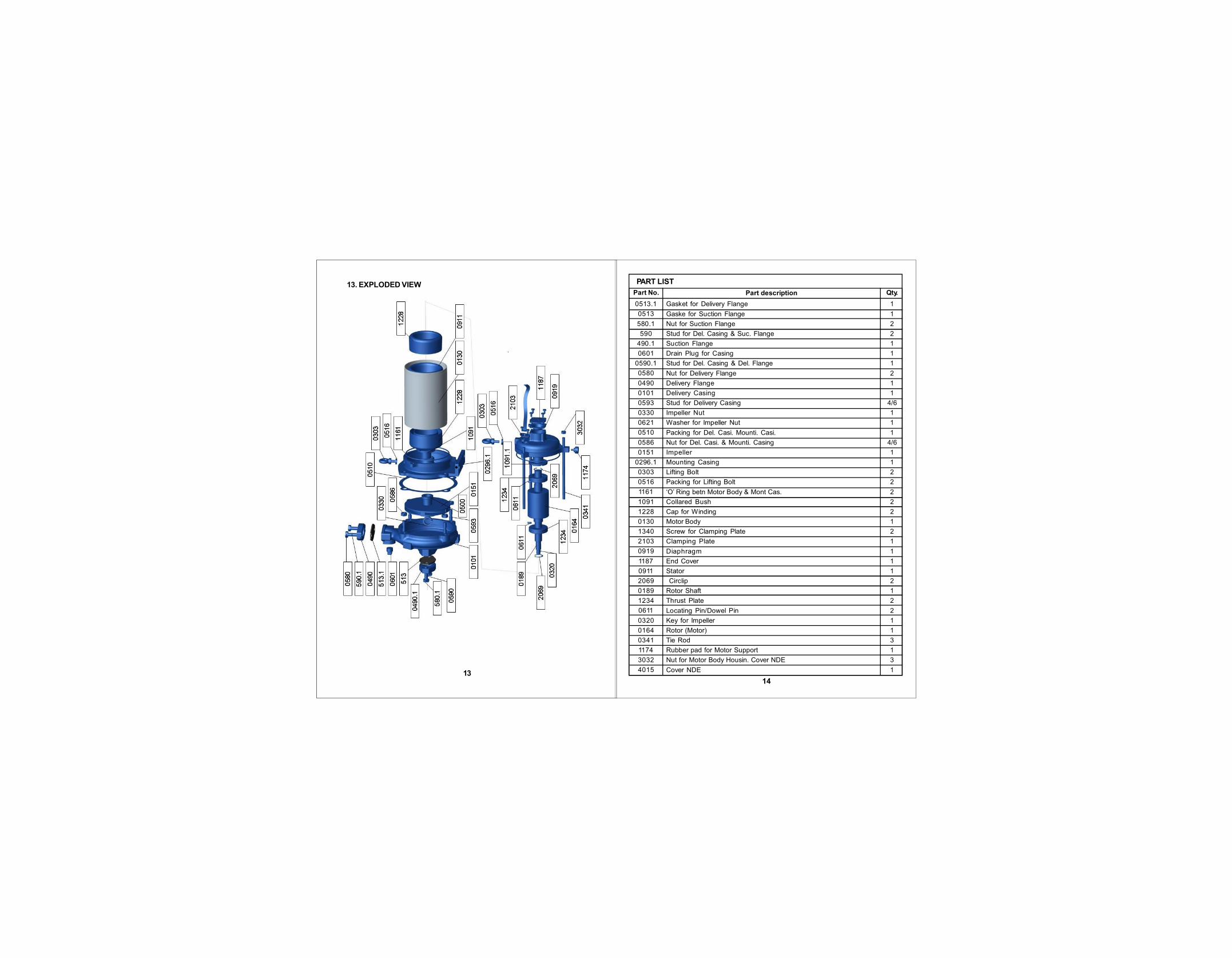
13. EXPLODED VIEW
13
PART LIST
14
Part descriptionPart No.
Gasket for Delivery Flange
Gaske for Suction Flange
Nut for Suction Flange
Stud for Del. Casing & Suc. Flange
Suction Flange
Drain Plug for Casing
Stud for Del. Casing & Del. Flange
Nut for Delivery Flange
Delivery Flange
Delivery Casing
Stud for Delivery Casing
Impeller Nut
Washer for Impeller Nut
Packing for Del. Casi. Mounti. Casi.
Nut for Del. Casi. & Mounti. Casing
Impeller
Mounting Casing
Lifting Bolt
Packing for Lifting Bolt
‘O’ Ring betn Motor Body & Mont Cas.
Collared Bush
Cap for Winding
Motor Body
Screw for Clamping Plate
Clamping Plate
Diaphragm
End Cover
Stator
Circlip
Rotor Shaft
Thrust Plate
Locating Pin/Dowel Pin
Key for Impeller
Rotor (Motor)
Tie Rod
Rubber pad for Motor Support
Nut for Motor Body Housin. Cover NDE
Cover NDE
Qty.
0513.1
0513
580.1
590
490.1
0601
0590.1
0580
0490
0101
0593
0330
0621
0510
0586
0151
0296.1
0303
0516
1161
1091
1228
0130
1340
2103
0919
1187
0911
2069
0189
1234
0611
0320
0164
0341
1174
3032
4015
1
1
2
2
1
1
1
2
1
1
4/6
1
1
1
4/6
1
1
2
2
2
2
2
1
2
1
1
1
1
2
1
2
2
1
1
3
1
3
1

15
14. OUTLINE DRAWING :
KOSN - SERIES PUMP
KOSN - 0520 PUMP
16M
OD
EL
SU
C.
DE
L.
LW
HW
1W
2H
1H
2H
3A
BC
DP
NS
KO
SN
-05
16
KO
SN
-08
27
KO
SN
-11
6
KO
SN
-12
3
KO
SN
-12
8
KO
SN
-12
8
KO
SN
-12
8
KO
SN
-13
4
KO
SN
-1.
522
KO
SN
-1.
525
KO
SN
-1.
540
KO
SN
-21
6
KO
SN
-22
5
KO
SN
-05
23
KO
SN
-05
27
25 25 50 32 25 40 50 25 50 50 32 65 50 25 25
25 25 40 25 25 40 40 25 40 40 25 40 40 25 25
295
373
373
365
378.
5
380.
5
380.
5
373
397
390
385
430.
5
416.
5
333
333
171
176.
5
189.
5
190.
5
186
187.
5
187.
5
176.
5
189.
5
187.
5
225
176
190.
5
185
185
26
8
250
.5
27
6
28
1
27
3
27
1
27
1
250
.5
27
6
27
1
29
8
26
0
28
1
26
2
26
2
82 86.8
88.5
91.5
90 91 91 86.8
88.5
91
112
.5
80 91.5
89.2
89.2
89 89.7
101
99 96 96.5
96.5
89.7
101
96.5
112
.5
96 99 95.5
95.5
110
10
5
110
10
5
10
5
10
5
10
5
10
5
110
10
5
12
5
10
0
10
5
97 97
128
115.
5
135
145
135
135
135
115.
5
135
135
146
132
148
135
135
30 30 28 28 30 28 28 30 28 28 24 28 28 27 27
25 73 71 70 78.5
64 64 73 71 64 66 73.5
73.7
78.5
78.5
30 30 32 25 30 32 32 30 32 32 25 32 32 27 27
23
21
28
27.5
23.5
23.5
23.5
21
28
23.5
21
34.5
29
23.5
23.5
14
2.7
13
3.7
19
8.2
12
5.7
13
9.2
12
6.7
12
6.7
13
3.7
19
8.2
19
1.2
12
1.7
20
0.7
20
0.7
14
1
14
1
39 39 39 39 39 39 39 39 39 39 39 50 39 44 44
133
163
163
163
163
163
163
163
187
187
187
204
204
140.
5
140.
5
68 68 68 68 68 68 68 68 68 68 68 68 68 33 33

17
Product range manufactured by Kirloskar Brothers Limited, Dewas
For details contact the dealer
Pump Series
KDS+/++
KDT+
KS+
KOS
SP
KJV/H,KJ+
MINI,DC,DHX
SubmersibleKu4 Winner
NW,KE,KHKHDT+,SR
KV, DV
Alternator
Motor
Construction Feature
Monobloc
Monobloc
Monobloc
Monobloc
Monobloc/Coupled
Monobloc
Monobloc
------------
Coupled
Monobloc/Coupled
------------
------------
Drive Unit
Electric Motor(1 and 3 Phase)Electric Motor(1 and 3 Phase)Electric Motor(1 and 3 Phase)Electric Sub. Motor(1 and 3 Phase)Electric Motor(Monobloc)Electric Motor(1 and 3 Phase)Electric Motor(1 and 3 Phase)Electric Sub. Motor(1 and 3 Phase)
Engine / Motor
Electric Motor
----------------
----------------
Power Rating
1.5 HP - 30.0 HP
1.0 HP - 20.0 HP
3.0 HP - 10.0 HP
0.5 HP - 10.0 HP
0.5 HP - 5.0 HP
0.5 HP - 3.0 HP
0.25 HP - 1.0 HP
0.5 HP - 75.0 HP
---------------------
---------------------
2 KVA - 50 KVA
0.5 HP - 120 HP
18
This product is warranted against manufacturing defects and workmanship under normal use and service for the period of 24 months from the date of manufacturing OR 12 months from date purchase of the end user whichever is earlier.
We undertake to repair or replace the product at our discretion or any partthereof, for which we are satisfied that it was originally defective in material or workmanship, provided that product or its parts are returned to our nearestregional office / dealer on freight paid basis, within the warranty period. Thiswarranty does not cover any consequential damage of any nature.
This warranty excludes every condition, whether statutory or otherwise, whatsoever is not expressly set out here.
Product Model:_________________________________________________
Sr. No. :______________________________________________________
Date of Purchase :_______________________________________________
Bill/Cash Memo No. :____________________________________________
SPECIAL INSTRUCTIONS: “ Customers are advised to go through the product manual carefully for proper installation, use and servicing product & genuine spare parts. It is also advisable to go through the company’s published literature, catalogue or other official publication. Any deviation, if made by the customers will void the warranty obligations. Repair by trained mechanics will get you better results.”
This card must be produced at the time of claiming the warranty along with purchase documents.
Dealer’s stamp and signature :___________________