Revised January 2007 Agdex 716 (C14) Submersible Pumpsdepartment/deptdocs...Submersible Pumps A...
3
Revised January 2007 Agdex 716 (C14) Submersible Pumps A submersible pump is a centrifugal pump (Figure 1), which is attached to an electric motor and oper- ates while submerged in water. The sealed electric motor spins a series of impellers (Figure 2). Each impeller in the series forces water through a diffuser into the eye of the one above it. In a typical 4 inch submersible pump, each impeller will add a approximately 9 psi of pressure. for example, a typ- ical 10-stage pump will develop a pressure of about 90 psi at its outlet (i.e.10 impellers x 9 psi). The capacity of the pump is determined by the width of the impeller vanes and its pressure by the number of impellers. As an example, a 1/2 horsepower 7-stage pump may deliver a high volume of water at a low pressure while a 1/2 horsepower 14-stage pump will deliver a lower volume but at a greater pressure. Like all other centrifugal pumps, an increase in well depth or discharge pressure will reduce the capacity. Figure 1. Submersible pump Figure2. Impeller Advantages Submersible pumps are efficient, high in capacity, require very little maintenance and are generally very economical for wells that are 80 feet or more in depth. Limitations The tolerances between the impellers and diffusers are relatively small; therefore, submersible pumps are unsuitable for pumping water that contains sand or other abrasives. Submersible pumps are water cooled and water lubricated. They should not be installed in wells that will pump dry, unless they are protected by a liquid level control. Submersible pumps are not suitable for pumping water containing a high concentration of dissolved gases because the pump may become gas locked. Most submersible pumps are designed for use in wells with a minimum 4 inch inside diameter.
Transcript of Revised January 2007 Agdex 716 (C14) Submersible Pumpsdepartment/deptdocs...Submersible Pumps A...

Revised January 2007 Agdex 716 (C14)
Submersible Pumps
A submersible pump is a centrifugal pump (Figure 1), which is attached to an electric motor and oper-ates while submerged in water. The sealed electric motor spins a series of impellers (Figure 2).
Each impeller in the series forces water through a diffuser into the eye of the one above it. In a typical 4 inch submersible pump, each impeller will add a approximately 9 psi of pressure. for example, a typ-ical 10-stage pump will develop a pressure of about 90 psi at its outlet (i.e.10 impellers x 9 psi).
The capacity of the pump is determined by the width of the impeller vanes and its pressure by the number of impellers. As an example, a 1/2 horsepower 7-stage pump may deliver a high volume of water at a low pressure while a 1/2 horsepower 14-stage pump will deliver a lower volume but at a greater pressure. Like all other centrifugal pumps, an increase in well depth or discharge pressure will reduce the capacity.
Figure 1. Submersible pump
Figure2. Impeller
AdvantagesSubmersible pumps are efficient, high in capacity, requirevery little maintenance and are generally very economicalfor wells that are 80 feet or more in depth.
LimitationsThe tolerances between the impellers and diffusers arerelatively small; therefore, submersible pumps areunsuitable for pumping water that contains sand or otherabrasives. Submersible pumps are water cooled and waterlubricated. They should not be installed in wells that willpump dry, unless they are protected by a liquid levelcontrol. Submersible pumps are not suitable for pumpingwater containing a high concentration of dissolved gasesbecause the pump may become gas locked.
Most submersible pumps are designed for use in wells with a minimum 4 inch inside diameter.
2
There are some available for use in wells with as small as a 3 inch inside diameter, but these are more expensive than comparable 4 inch pumps.
Use caution in selecting the submersible pump mostsuitable for a given well and application. Pump selectionshould be based on the desired pump capacity and the safepumping capacity of the well. Do not allow a pump to“over pump” a well. For example, if the well is onlycapable of pumping 5 gallons per minute, do not install apump that is capable of pumping 10 gallons per minute.The well and the pump can both be damaged and lifeexpectancy reduced. If a pump is capable of producingwellhead pressure in excess of 80-100 psi, an emergencypressure relief valve may be needed, just in case thepressure switch fails in the “on” position.
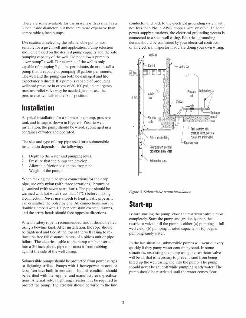
InstallationA typical installation for a submersible pump, pressure tank and fittings is shown in Figure 3. Prior to well installation, the pump should be wired, submerged in a container of water and operated.
The size and type of drop pipe used for a submersible installation depends on the following:
1. Depth to the water and pumping level. 2. Pressure that the pump can develop. 3. Allowable friction loss in the drop pipe. 4. Weight of the pump.
When making male adaptor connections for the drop pipe, use only nylon (with three serrations), bronze or galvanized (with seven serrations). The pipe should be warmed with hot water (less than 65°C) before making a connection. Never use a torch to heat plastic pipe as it can crystallize the polyethylene. All connections must be double clamped with 100 per cent stainless steel clamps, and the screw heads should face opposite directions.
A nylon safety rope is recommended, and it should be tied using a bowline knot. After installation, the rope should be tightened and tied at the top of the well casing to re-duce the free fall distance in case of a pitless unit or pipe failure. The electrical cable to the pump can be inserted into a 3/4 inch plastic pipe to protect it from rubbing against the side of the well casing.
Submersible pumps should be protected from power surges or lightning strikes. Pumps with 1 horsepower motors or less often have built-in protection, but this condition should be verified with the supplier and manufacturer’s specifica-tions. Alternatively, a lightning arrestor may be required to protect the pump. The arrestor should be wired to the line
conductor and back to the electrical grounding system with not less than No. 6 AWG copper wire or cable. In some power supply situations, the electrical grounding system is connected to a steel well casing. Electrical grounding details should be confirmed by your electrical contractor or an electrical inspector if you are doing your own wiring.
Figure 3. Submerisble pump installation
Start-upBefore starting the pump, close the restrictor valve almostcompletely. Start the pump and gradually open therestrictor valve until the pump is either (a) pumping at fullwell yield, (b) pumping at rated capacity, or (c) beginspumping sandy water.
In the last situation, submersible pumps will wear out veryquickly if they pump water containing sand. In somesituations, restricting the pump using the restrictor valvewill be all that is necessary to prevent sand from beinglifted up the well casing and into the pump. The pumpshould never be shut off while pumping sandy water. Thepump should be restricted until the water comes clear.
3
Maintenance No regular maintenance is required on submersible pumps. When a three-wire submersible pump fails, check the pump control box with electrical meters before removing the pump from the well.
For more Information
Alberta Ag-Info CentreCall toll-free: 310-FARM
Website: www.agriculture.alberta.ca
Prepared by:Alberta Agriculture and Rural Development
R07/01/500