KIP c7800 Service Manual Ver B_0.pdf
705
KIP C7800 Service Manual Version B.0
Transcript of KIP c7800 Service Manual Ver B_0.pdf

KIP C7800 Service Manual
Version B.0

K125sm1e1 1-1
Chapter 1
Introduction Page 1. 1 Features 1- 2 1. 2 Specifications 1- 3 1. 3 Appearance 1- 5 1. 3. 1 Front view 1- 5 1. 3. 2 Right side view 1- 6 1. 3. 3 Rear view 1- 7 1. 4 Specifications for the Printing Paper 1- 9
1. 4. 1 Papers not available to use 1- 9 1. 4. 2 Keeping the paper in the custody 1-10 1. 4. 3 Treatment against environmental condition 1-11
K125sm1e1 1-2
1. 1 Features (1) Electro Photographic full color LED printer (2) Supports wide range of print size, 914mm (36”) width x 6,000mm length maximum, 297mm (11”) x 210mm (8.5”) minimum. (3) 600dpi print resolutions produce the highest quality images controlled by an advanced KIP Image Process System. (4) Drastically reliable media transportability brought by Media Feed Belt Conveyer system allows stability of creating excellent image quality and long media feeding.
(5) CMYK process systems in tandem, resulting in smaller footprint, provides high performance productivity of 4.7 prints/minute of A0 color printing. (Color Print: 100mm/s maximum, Mono: 120mm/s) (6) Four color toner allows a broad selection of media type for Folor printing, such as a plain paper / bond roll media, saving consumables cost than a wide format inkjet printer. (7) Prints are available to use immediately, free from drying time and wrinkling by the KIP C7800 dry toner. (8) Easy access to the front USB port allows the users for efficient productivity “USB to Print”. (9) Touch screen Operating Panel offers an intuitive UI for advanced operability to configure and submit a print job. (10) Includes Print Tray for stacking prints as a standard accessory. High capacity Auto Stacker is available (option).
K125sm1e1 1-3
1. 2 Specifications Subject Specification Model KIP c7800 Type Console Printing method LED Array Electro Photography Color CMYK Photoconductor Organic Photoconductive Drum Print speed Color : 100mm / second max. (4.6ppm / 36”x48”) (4.7ppm / A0)
(for Roll Deck 3), speed varies by media type) Mono : 120mm / second Heavy : 60mm / second (Gross)
Exposure method Multi-Level (tone number 9) LED Print Head Resolution 600dpi x 2400dpi Print width Maximum : 914mm (36 inches)
Minimum : 297mm (11 inches) Print length Maximum :
Minimum : 210mm (8.5 inches) NOTE : If the print is longer than 6m, KIP does not guarantee image quality or the reliability of media feeding system.
Plain Paper / Bond 5x Standard Roll Deck 3 2x Standard Roll Deck 1, 2
Tracing Paper / Vellum 1x Standard Film 1x Standard Glossy Paper 1x Standard
Warm up time Shorter than 6 minutes (At 23 degrees centigrade, 60% RH and 220V)
First print time Shorter than 35 seconds (36 x 48 inches) (for Roll Deck 3, Color) Fusing method Heat roller fusing Development Contact type mono component non-magnetic development system
(Initial toner is unnecessary. One toner cartridge contains 1kg.) Charging method Corona Transfer method Transfer roller Media feeding method Automatic (*3 Roll Decks) and manual (**20 cut sheets capacity)
* Image quality on A3, 15”, 12”, 11” width roll media is guaranteed with
using Roll Deck 3 only ** A2 - A4 (24” - 11”) in Landscape orientation only
Input power 220 to 240V (+6% to -10%), 20A and 50/60Hz Interface Ethernet 10BASE-T, 100 BASE –TX, 1000 BASE-T
USB 2.0 (5VDC max) Power consumption On 230V, 50/60Hz 3.6 kw (Maximum)
Stand by 0.8 Kwh (Average) Printing 2.2 Kwh (Average) Warm up 3.4 Kwh (Average)
Acoustic noise Less than 65db (Printing) NOTE : Impact noise such as cutting sound is excluded. Less than 60db (Stand by)
Ozone Less than 0.05ppm (Average of 8 hours) Dimensions 1376mm (Width) x 790mm (Depth) x 1450mm (Height) Weight About 540kg

K125sm1e1 1-4
Subject Specification Media Plain Paper / Bond:
Color mode: 70 to 150g/m2 * For heavier media (90 to 150g/m2), use media type setting “Heavy”.Mono mode: 70 to 75g/m2
Environmental condition
Temperature 15 to 27 degrees centigrade Humidity 20 to 70% RH
Storage condition of consumables
Print media Wrap the media surely to shut out the humidity. Toner Keep the toner cartridge away from the direct sunlight, and store it in the condition of 0 - 35 oC and 10 - 85% RH.
NOTE These specifications may be changed without notice.
K125sm1e1 1-5
1. 3 Appearance
1. 3. 1 Front view
Name of part Function Power Switch Turns on/off the KIP C7800. Bypass Feeder Feeds in the cut sheet media.
50 sheets can be set at once if the media is A2 (594mm) or smaller. (24” or narrower)
User Interface
This is a Touch Screen, and many kinds of user operation are available. PLEASE DO NOT push the LCD area too strong.
Stack Tray Supports cut sheets loaded on Bypass Feeder. Roll Decks 3 roll media can be set totally. USB Port Your USB flash memory storage can be installed here.
5VDC max. LAN Cable Connects to the network. (Purchase a LAN Cable separately) Status Indicator LED indicator above the power switch indicates the following
printer status.
User Interface
Bypass Feeder
Roll Decks
Power Switch
USB Port
Status Indicator
Color Condition StatusGreen Light Ready, PrintingGreen Blink Warming up.Orange Light Operator Call Error Red Light Service Call Error Blue Light Warm sleepBlue Blink Cold sleeplight purple Blink When printer is power-off and print controller is
still power on.
Stack Tray
LAN Cable
K125sm1e1 1-6
1. 3. 2 Left side view
Name of part Function Toner Cartridge 4 Toner Cartridges (cyan, magenta, yellow and black) supplies the
toner little by little. Fuser Handle Can eject mis-fed media from the Fuser Unit by rotating the Fuser
Handle when the media is mis-fed in the Fuser Unit. Left Side Door Open here to replace the Toner Cartridge.
Toner Cartridge
Left Side Door
Fuser Handle
K125sm1e1 1-7
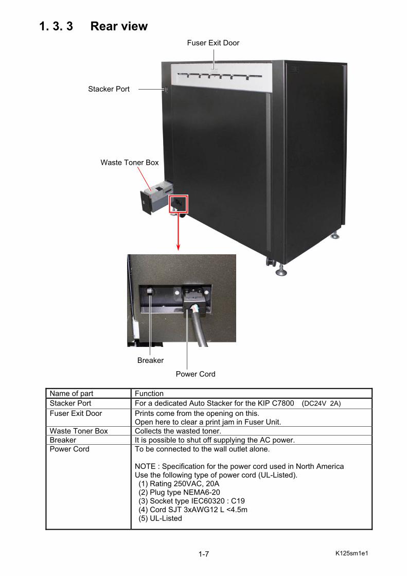
1. 3. 3 Rear view
Name of part Function Stacker Port For a dedicated Auto Stacker for the KIP C7800 (DC24V 2A) Fuser Exit Door Prints come from the opening on this.
Open here to clear a print jam in Fuser Unit. Waste Toner Box Collects the wasted toner. Breaker It is possible to shut off supplying the AC power. Power Cord To be connected to the wall outlet alone.
NOTE : Specification for the power cord used in North America Use the following type of power cord (UL-Listed). (1) Rating 250VAC, 20A (2) Plug type NEMA6-20 (3) Socket type IEC60320 : C19 (4) Cord SJT 3xAWG12 L <4.5m (5) UL-Listed
Fuser Exit Door
Stacker Port
Breaker
Power Cord
Waste Toner Box
K125sm1e1 1-8
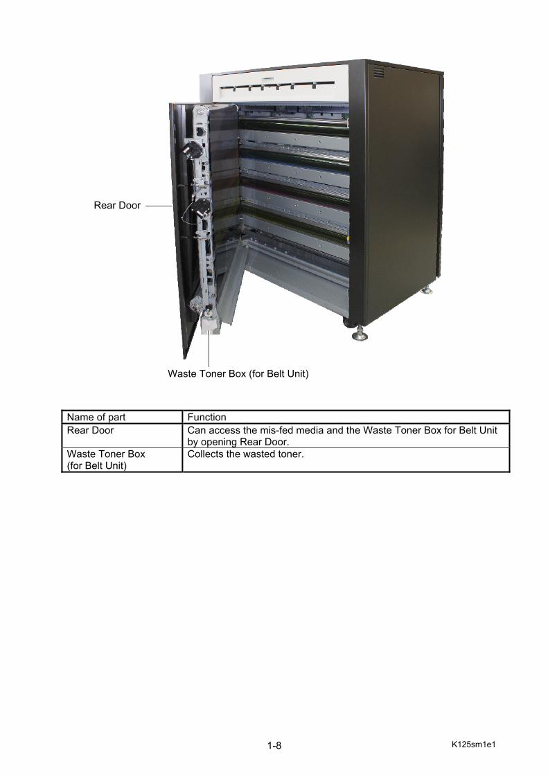
Name of part Function Rear Door Can access the mis-fed media and the Waste Toner Box for Belt Unit
by opening Rear Door. Waste Toner Box (for Belt Unit)
Collects the wasted toner.
Waste Toner Box (for Belt Unit)
Rear Door
K125sm1e1 1-9
1. 4 Specifications for the Printing Paper
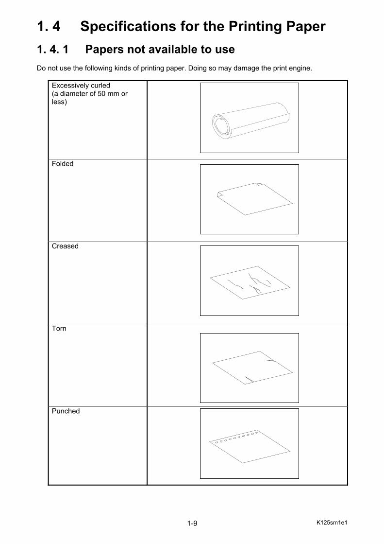
1. 4. 1 Papers not available to use Do not use the following kinds of printing paper. Doing so may damage the print engine.
Excessively curled (a diameter of 50 mm or less)
Folded
Creased
Torn
Punched
K125sm1e1 1-10
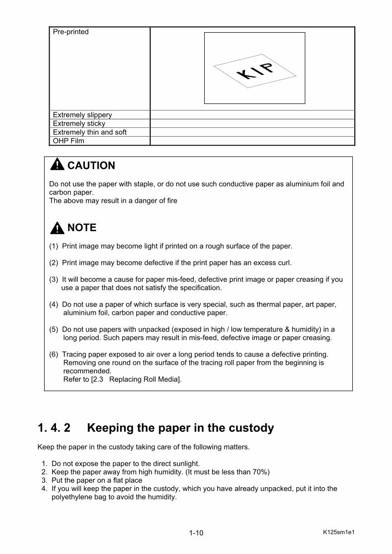
Pre-printed
Extremely slippery Extremely sticky Extremely thin and soft OHP Film
1. 4. 2 Keeping the paper in the custody Keep the paper in the custody taking care of the following matters. 1. Do not expose the paper to the direct sunlight. 2. Keep the paper away from high humidity. (It must be less than 70%) 3. Put the paper on a flat place 4. If you will keep the paper in the custody, which you have already unpacked, put it into the polyethylene bag to avoid the humidity.
CAUTION Do not use the paper with staple, or do not use such conductive paper as aluminium foil and carbon paper. The above may result in a danger of fire NOTE (1) Print image may become light if printed on a rough surface of the paper. (2) Print image may become defective if the print paper has an excess curl. (3) It will become a cause for paper mis-feed, defective print image or paper creasing if you use a paper that does not satisfy the specification. (4) Do not use a paper of which surface is very special, such as thermal paper, art paper, aluminium foil, carbon paper and conductive paper. (5) Do not use papers with unpacked (exposed in high / low temperature & humidity) in a long period. Such papers may result in mis-feed, defective image or paper creasing. (6) Tracing paper exposed to air over a long period tends to cause a defective printing. Removing one round on the surface of the tracing roll paper from the beginning is recommended. Refer to [2.3 Replacing Roll Media].
K125sm1e1 1-11
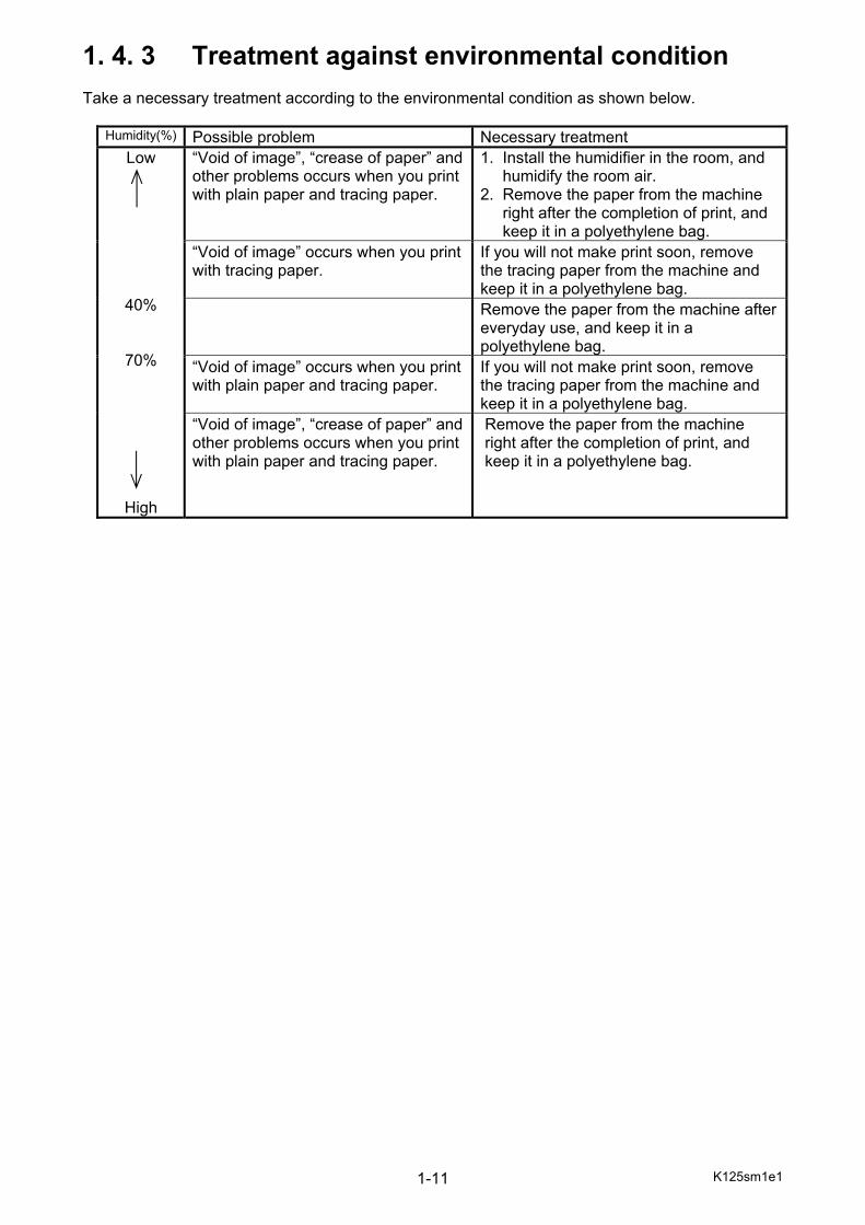
1. 4. 3 Treatment against environmental condition Take a necessary treatment according to the environmental condition as shown below.
Humidity(%) Possible problem Necessary treatment Low
40%
70%
High
“Void of image”, “crease of paper” and other problems occurs when you print with plain paper and tracing paper.
1. Install the humidifier in the room, and humidify the room air. 2. Remove the paper from the machine right after the completion of print, and keep it in a polyethylene bag.
“Void of image” occurs when you print with tracing paper.
If you will not make print soon, remove the tracing paper from the machine and keep it in a polyethylene bag.
Remove the paper from the machine after everyday use, and keep it in a polyethylene bag.
“Void of image” occurs when you print with plain paper and tracing paper.
If you will not make print soon, remove the tracing paper from the machine and keep it in a polyethylene bag.
“Void of image”, “crease of paper” and other problems occurs when you print with plain paper and tracing paper.
Remove the paper from the machine right after the completion of print, and keep it in a polyethylene bag.

K125sm2e1 2-1
Chapter 2
Installation
Page
2. 1 Installation Requirements 2- 3 2. 2 Unpacking 2- 4 2. 2. 1 Unpacking 2- 4 2. 2. 2 Confirmation of accessories 2- 5 2. 3 Leveling KIP C7800 2- 7 2. 4 Routing the LAN Cable 2-20 2. 5 Removing Tapes, Shock Absorbers and Screws 2-21 2. 6 Setting up the Process Unit (Developer, Cleaner & Drum) 2-31 2. 6. 1 Setting up the Developer Unit 2-31 2. 6. 2 Applying the toner to the Cleaning Blade 2-33 2. 6. 3 Installing the Drum 2-36 2. 6. 4 Installing the Toner Cartridge 2-45 2. 7 Installing the Web Cleaner 2-47 2. 8 Reconfirmation of Level 2-53 2. 9 Installing the Bypass Feeder Tray 2-55 2. 10 IPS Setup Wizard 2-56 2. 11 Print Format (metric/inch - if necessary) 2-63 2. 12 Supplying Toner into Developer Unit 2-67 2. 13 Setting Auto Density Control to “auto std” 2-72 2. 14 Executing Auto Adjustments 2-75 2. 15 Check and Touch-up LED Head Joint 2-79 2.15. 1 Check the result of LED Head Joint 2-79 2.15. 2 Touch-up LED Head Joint 2-83 2. 16 Check and Touch-up Color Registration 2-89 2.16. 1 Check the result of Color Registration 2-90 2.16. 2 Touch-up Color Registration 2-92 2. 17 Confirm LED Head Joint Control is set to “manual” 2-97 POWER CORD INSTRUCTION 2-101
K125sm2e1 2-2
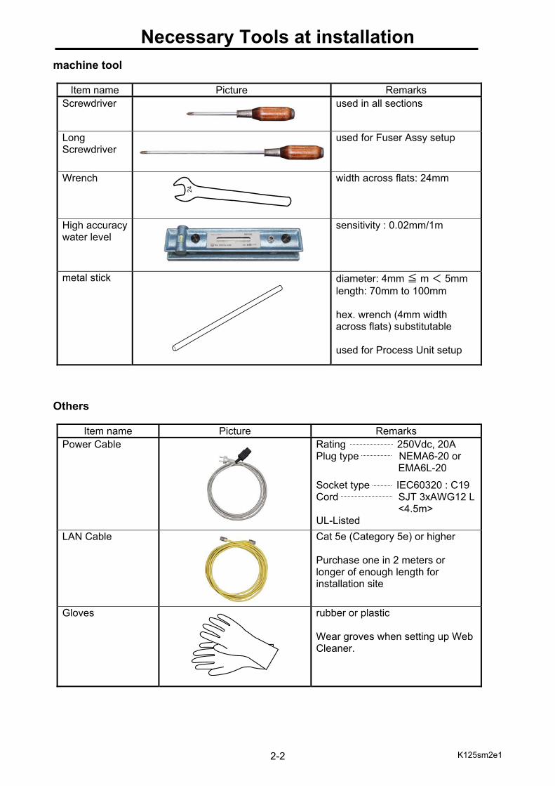
Necessary Tools at installation machine tool
Item name Picture Remarks Screwdriver used in all sections
Long Screwdriver
used for Fuser Assy setup
Wrench
width across flats: 24mm
High accuracy water level
sensitivity : 0.02mm/1m
metal stick
diameter: 4mm ≦ m < 5mm length: 70mm to 100mm hex. wrench (4mm width across flats) substitutable used for Process Unit setup
Others
Item name Picture Remarks Power Cable Rating 250Vdc, 20A
Plug type NEMA6-20 or EMA6L-20
Socket type IEC60320 : C19 Cord SJT 3xAWG12 L
<4.5m> UL-Listed
LAN Cable Cat 5e (Category 5e) or higher Purchase one in 2 meters or longer of enough length for installation site
Gloves rubber or plastic Wear groves when setting up Web Cleaner.
K125sm2e1 2-3
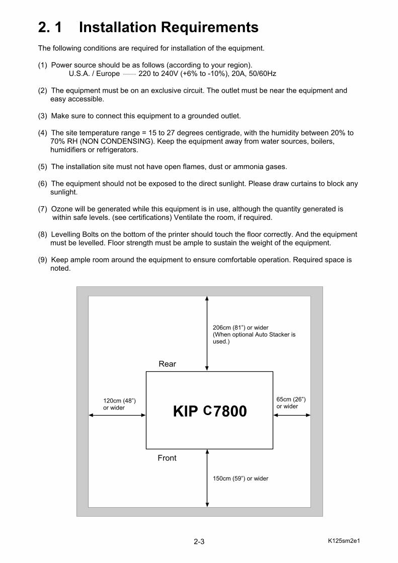
2. 1 Installation Requirements The following conditions are required for installation of the equipment. (1) Power source should be as follows (according to your region). U.S.A. / Europe 220 to 240V (+6% to -10%), 20A, 50/60Hz (2) The equipment must be on an exclusive circuit. The outlet must be near the equipment and easy accessible. (3) Make sure to connect this equipment to a grounded outlet. (4) The site temperature range = 15 to 27 degrees centigrade, with the humidity between 20% to 70% RH (NON CONDENSING). Keep the equipment away from water sources, boilers, humidifiers or refrigerators. (5) The installation site must not have open flames, dust or ammonia gases. (6) The equipment should not be exposed to the direct sunlight. Please draw curtains to block any sunlight. (7) Ozone will be generated while this equipment is in use, although the quantity generated is within safe levels. (see certifications) Ventilate the room, if required. (8) Levelling Bolts on the bottom of the printer should touch the floor correctly. And the equipment must be levelled. Floor strength must be ample to sustain the weight of the equipment. (9) Keep ample room around the equipment to ensure comfortable operation. Required space is noted.
206cm (81”) or wider (When optional Auto Stacker is used.)
120cm (48”) or wider
150cm (59”) or wider
65cm (26”) or wider
Rear
Front
K125sm2e1 2-4
2. 2 Unpacking
2. 2. 1 Unpacking
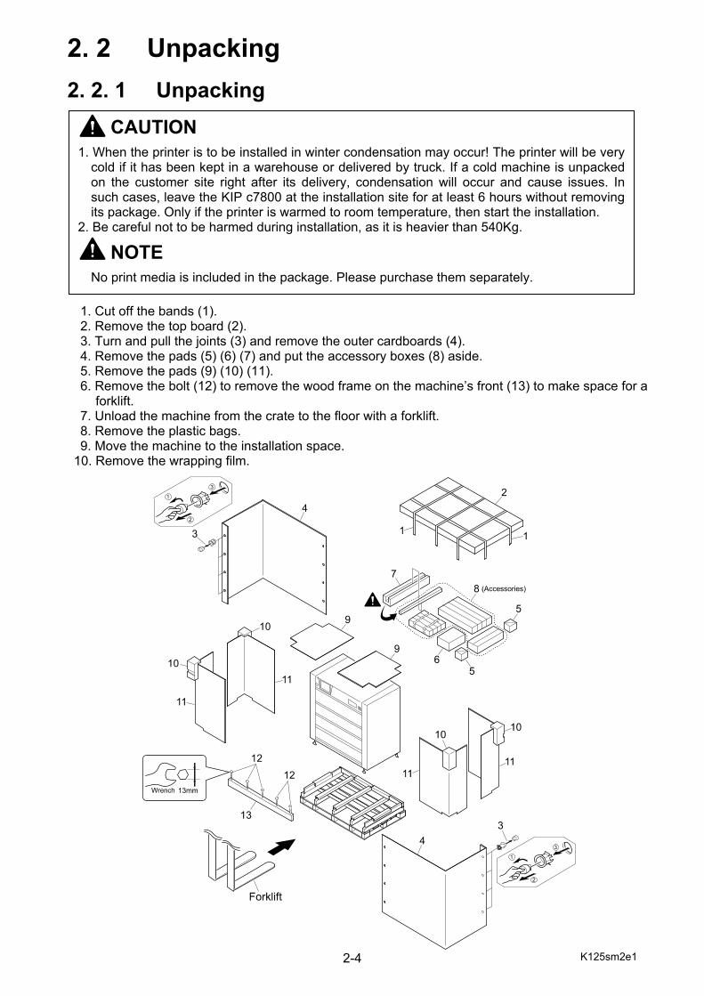
1. Cut off the bands (1). 2. Remove the top board (2). 3. Turn and pull the joints (3) and remove the outer cardboards (4). 4. Remove the pads (5) (6) (7) and put the accessory boxes (8) aside. 5. Remove the pads (9) (10) (11). 6. Remove the bolt (12) to remove the wood frame on the machine’s front (13) to make space for a
forklift. 7. Unload the machine from the crate to the floor with a forklift. 8. Remove the plastic bags. 9. Move the machine to the installation space.
10. Remove the wrapping film.
CAUTION
1. When the printer is to be installed in winter condensation may occur! The printer will be very cold if it has been kept in a warehouse or delivered by truck. If a cold machine is unpacked on the customer site right after its delivery, condensation will occur and cause issues. In such cases, leave the KIP c7800 at the installation site for at least 6 hours without removing its package. Only if the printer is warmed to room temperature, then start the installation.
2. Be careful not to be harmed during installation, as it is heavier than 540Kg.
NOTE
No print media is included in the package. Please purchase them separately.
K125sm2e1 2-5
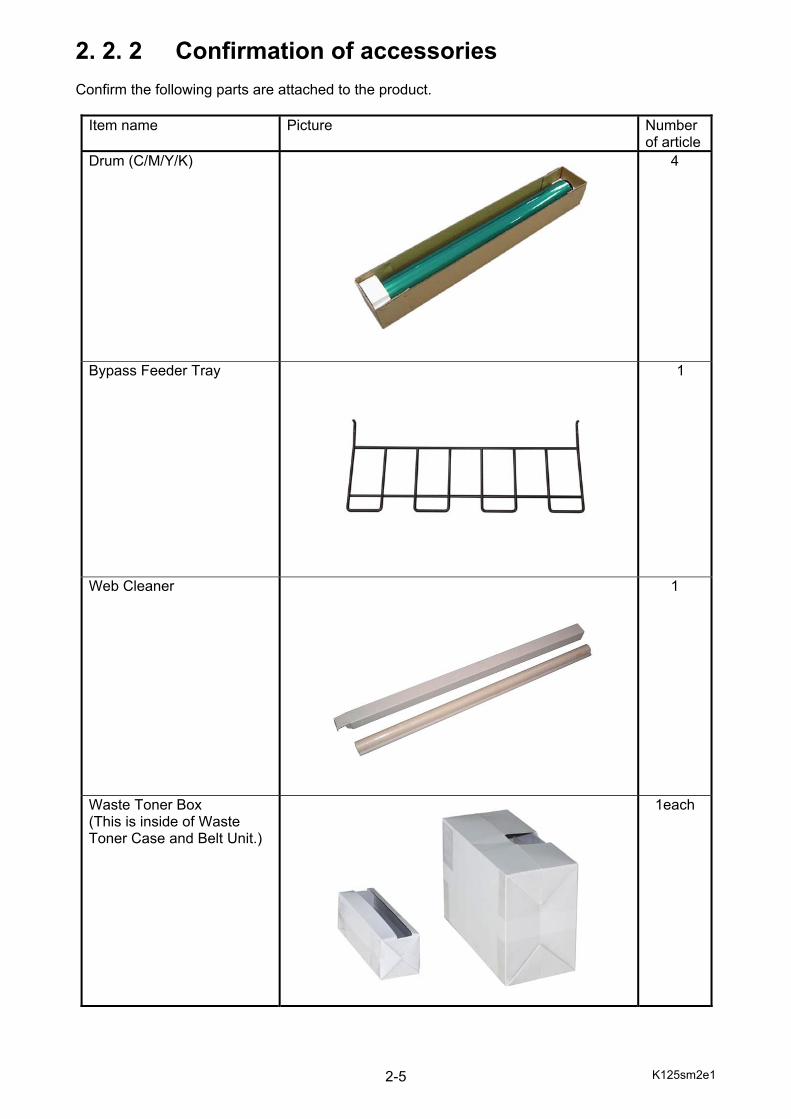
2. 2. 2 Confirmation of accessories Confirm the following parts are attached to the product.
Item name Picture Number of article
Drum (C/M/Y/K)
4
Bypass Feeder Tray 1
Web Cleaner 1
Waste Toner Box (This is inside of Waste Toner Case and Belt Unit.)
1each
K125sm2e1 2-6
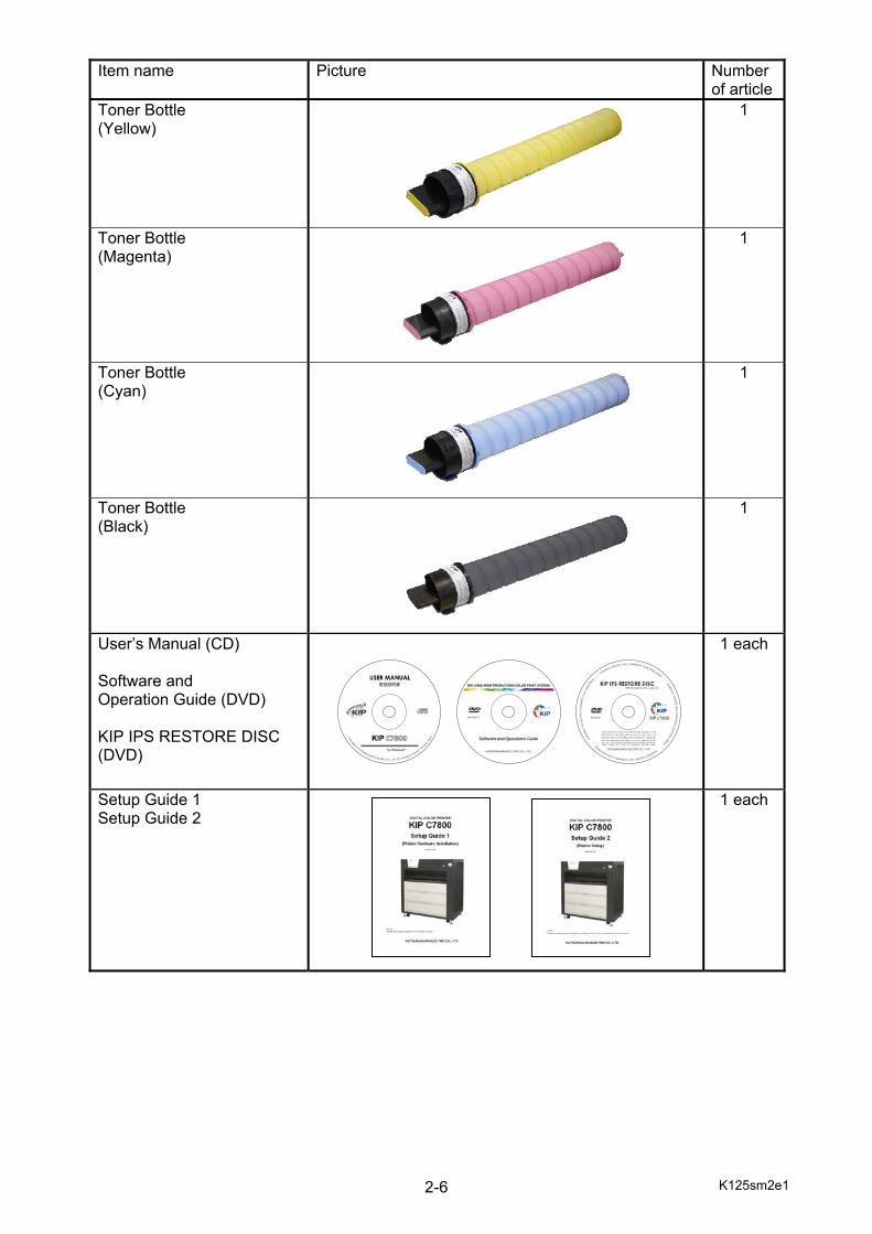
Item name Picture Number
of articleToner Bottle (Yellow)
1
Toner Bottle (Magenta)
1
Toner Bottle (Cyan)
1
Toner Bottle (Black)
1
User’s Manual (CD) Software and Operation Guide (DVD) KIP IPS RESTORE DISC (DVD)
1 each
Setup Guide 1 Setup Guide 2
1 each
K125sm2e1 2-7
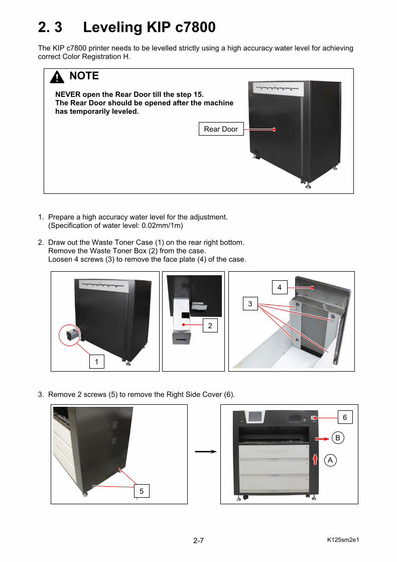
2. 3 Leveling KIP c7800 The KIP c7800 printer needs to be levelled strictly using a high accuracy water level for achieving correct Color Registration H. 1. Prepare a high accuracy water level for the adjustment. (Specification of water level: 0.02mm/1m) 2. Draw out the Waste Toner Case (1) on the rear right bottom.
Remove the Waste Toner Box (2) from the case. Loosen 4 screws (3) to remove the face plate (4) of the case.
3. Remove 2 screws (5) to remove the Right Side Cover (6).
5
1
2
4
3
6
NOTE NEVER open the Rear Door till the step 15. The Rear Door should be opened after the machine has temporarily leveled.
Rear Door
A
B
K125sm2e1 2-8
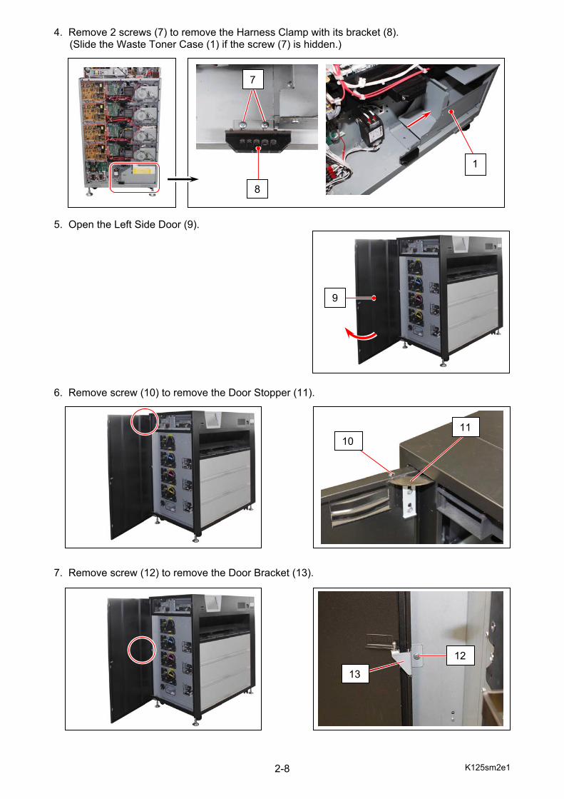
4. Remove 2 screws (7) to remove the Harness Clamp with its bracket (8). (Slide the Waste Toner Case (1) if the screw (7) is hidden.)
5. Open the Left Side Door (9). 6. Remove screw (10) to remove the Door Stopper (11). 7. Remove screw (12) to remove the Door Bracket (13).
9
1011
12
13
7
8
1
K125sm2e1 2-9
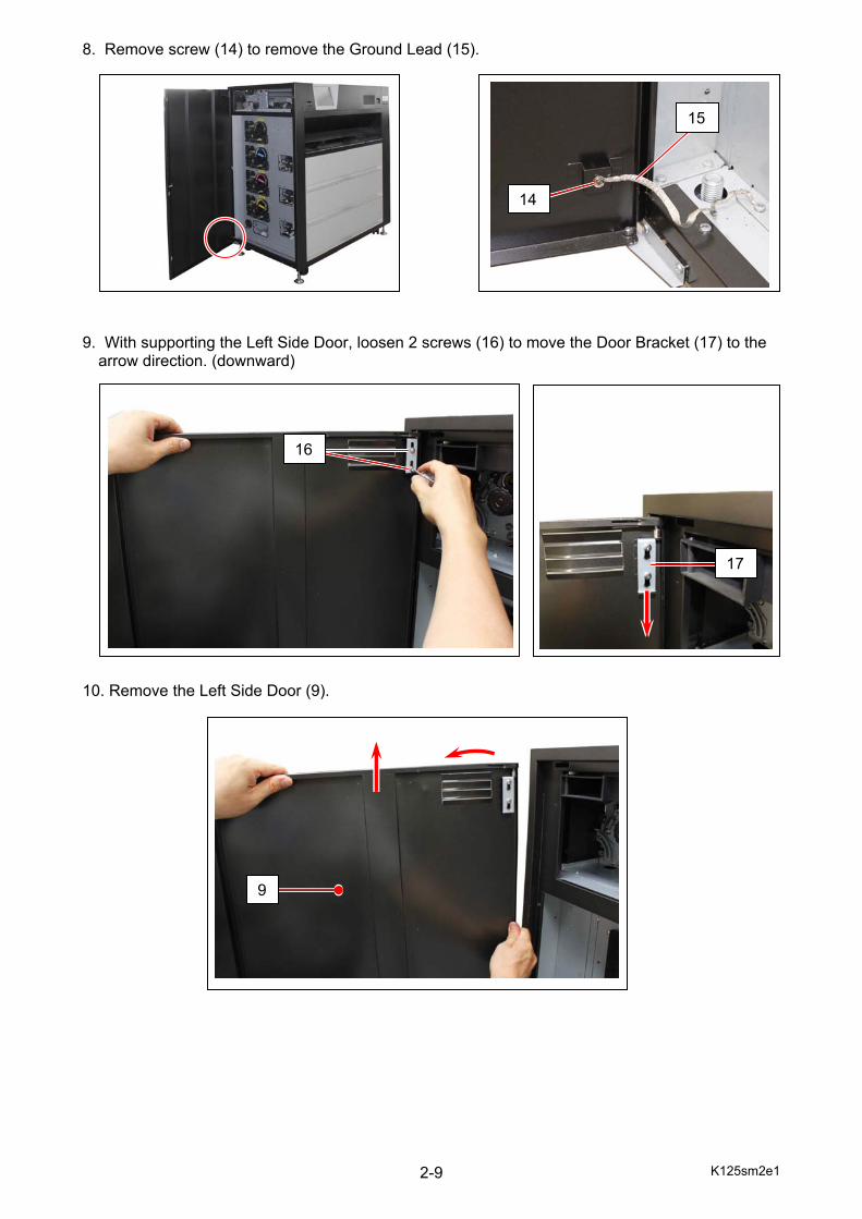
8. Remove screw (14) to remove the Ground Lead (15). 9. With supporting the Left Side Door, loosen 2 screws (16) to move the Door Bracket (17) to the
arrow direction. (downward) 10. Remove the Left Side Door (9).
14
15
16
9
17
K125sm2e1 2-10
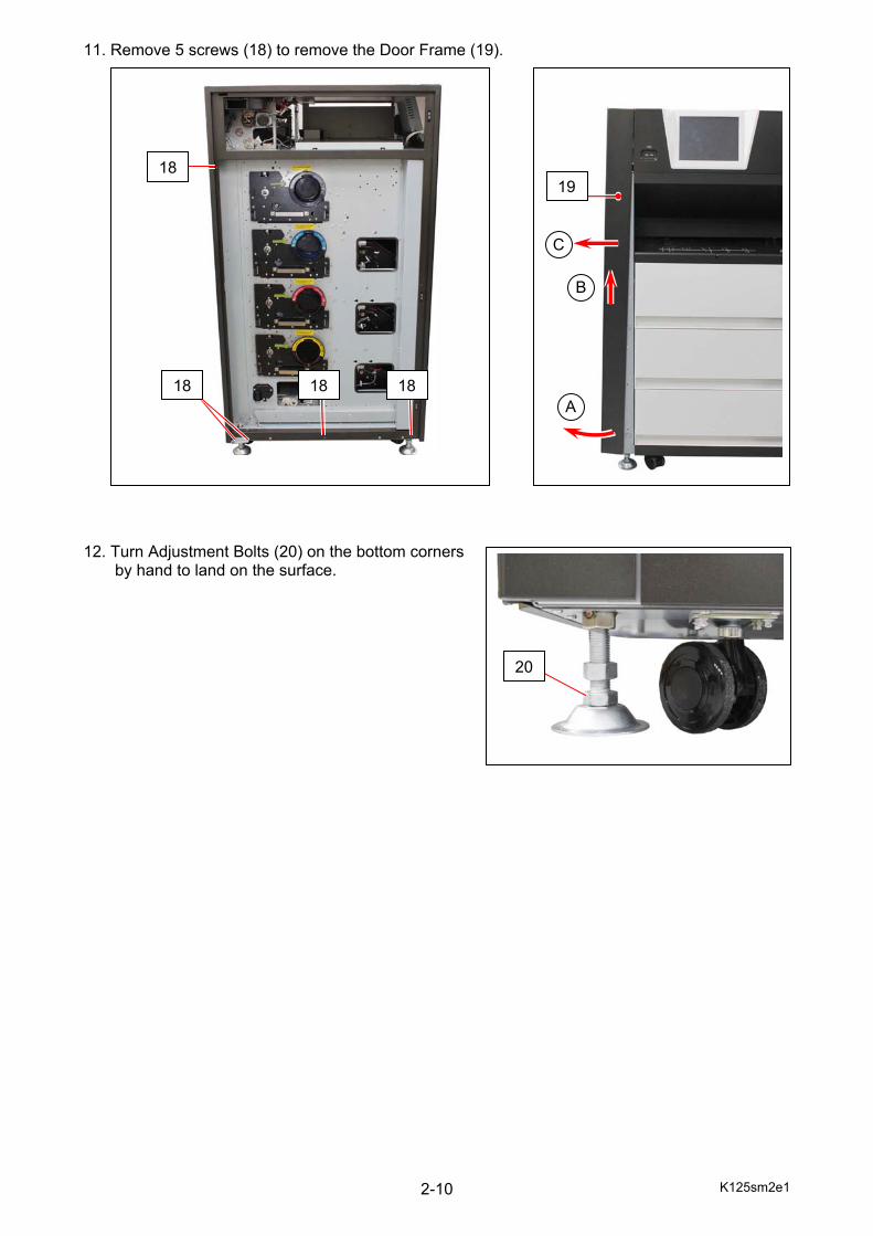
11. Remove 5 screws (18) to remove the Door Frame (19). 12. Turn Adjustment Bolts (20) on the bottom corners by hand to land on the surface.
18
18 18 18
19
20
A
B
C
K125sm2e1 2-11
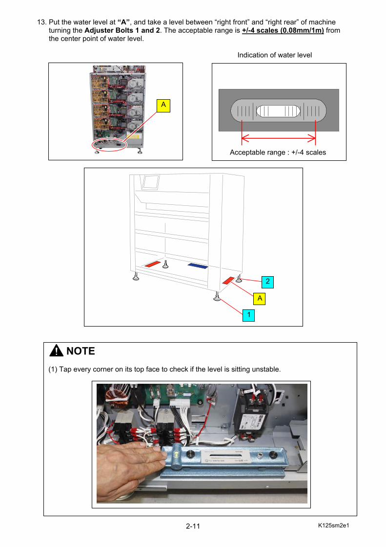
13. Put the water level at “A”, and take a level between “right front” and “right rear” of machine turning the Adjuster Bolts 1 and 2. The acceptable range is +/-4 scales (0.08mm/1m) from the center point of water level. Indication of water level
Acceptable range : +/-4 scales
NOTE (1) Tap every corner on its top face to check if the level is sitting unstable.
A
1
2
A
K125sm2e1 2-12
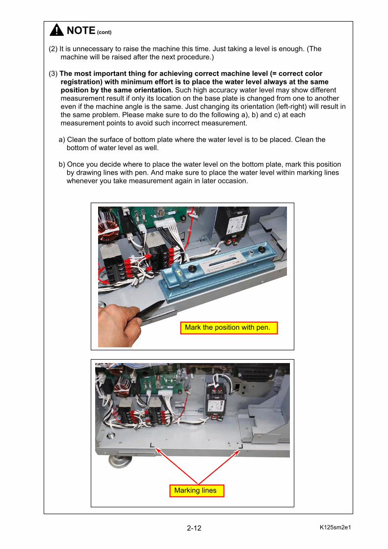
NOTE (cont) (2) It is unnecessary to raise the machine this time. Just taking a level is enough. (The machine will be raised after the next procedure.) (3) The most important thing for achieving correct machine level (= correct color registration) with minimum effort is to place the water level always at the same position by the same orientation. Such high accuracy water level may show different measurement result if only its location on the base plate is changed from one to another even if the machine angle is the same. Just changing its orientation (left-right) will result in the same problem. Please make sure to do the following a), b) and c) at each measurement points to avoid such incorrect measurement. a) Clean the surface of bottom plate where the water level is to be placed. Clean the bottom of water level as well. b) Once you decide where to place the water level on the bottom plate, mark this position by drawing lines with pen. And make sure to place the water level within marking lines whenever you take measurement again in later occasion.
Mark the position with pen.
Marking lines
K125sm2e1 2-13
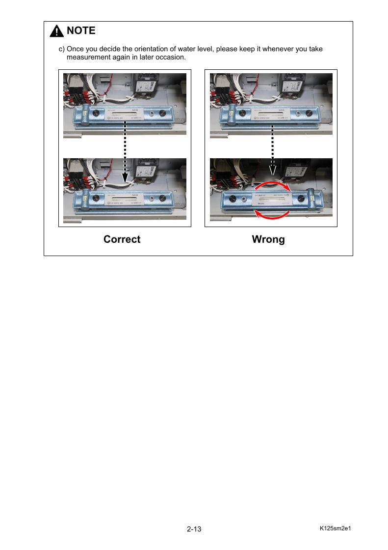
NOTE c) Once you decide the orientation of water level, please keep it whenever you take measurement again in later occasion.
Wrong Correct

K125sm2e1 2-14
14. Put the water level at “B”, and take a level between “left front” and “left rear” of machine turning the Adjuster Bolts 3 and 4. The acceptable range is +/-4 scales (0.08mm/1m) from the center point of water level. Indication of water level
Acceptable range : +/-4 scales
NOTE It is unnecessary to raise the machine this time. Just taking a level is enough. (The machine will be raised after the next procedure.)
4
B
3
B
K125sm2e1 2-15
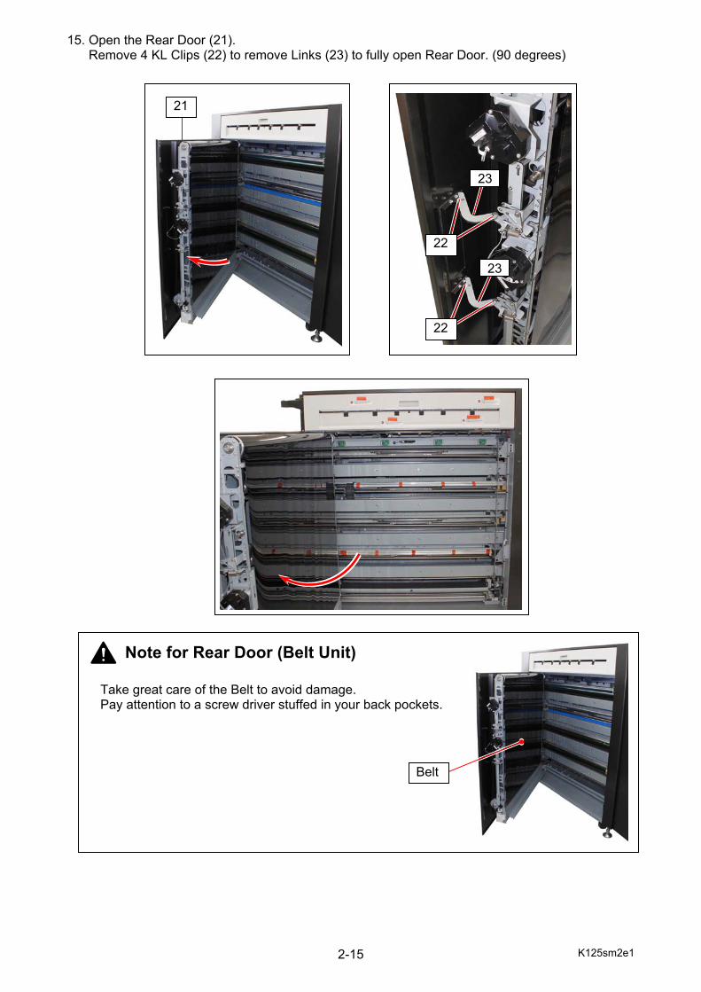
15. Open the Rear Door (21). Remove 4 KL Clips (22) to remove Links (23) to fully open Rear Door. (90 degrees)
21
Take great care of the Belt to avoid damage. Pay attention to a screw driver stuffed in your back pockets.
Note for Rear Door (Belt Unit)
Belt
23
23
22
22
K125sm2e1 2-16
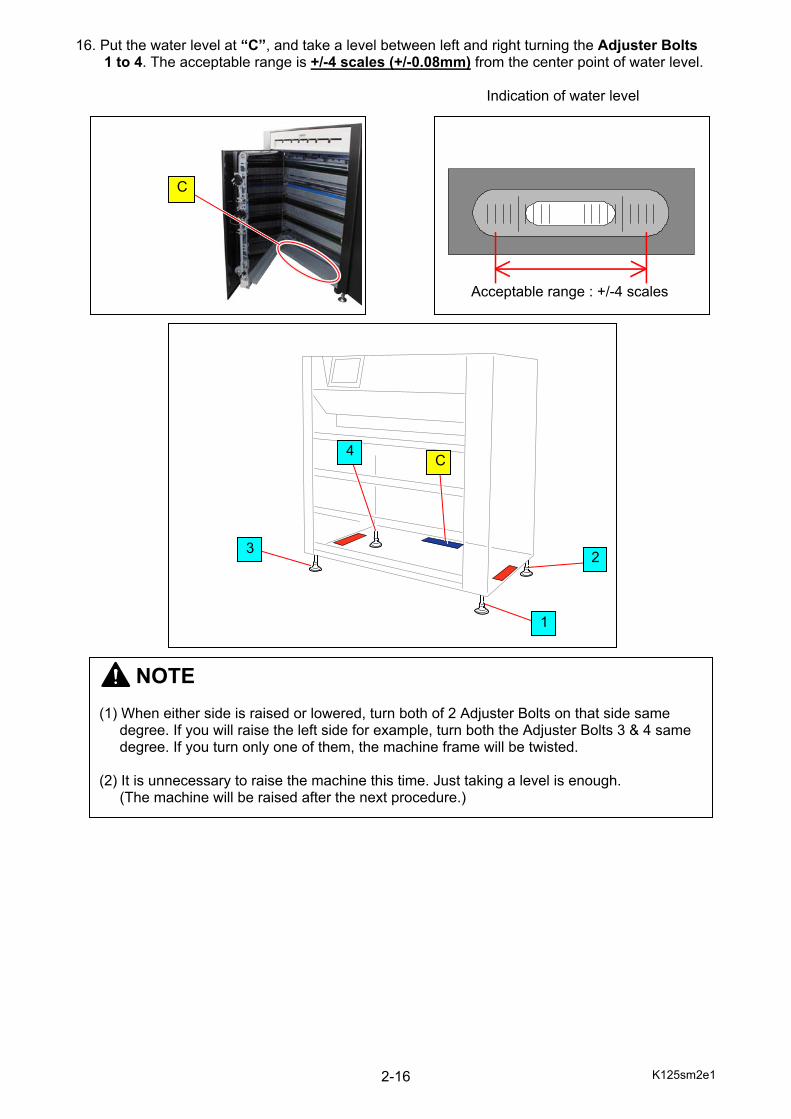
16. Put the water level at “C”, and take a level between left and right turning the Adjuster Bolts 1 to 4. The acceptable range is +/-4 scales (+/-0.08mm) from the center point of water level. Indication of water level
Acceptable range : +/-4 scales
NOTE (1) When either side is raised or lowered, turn both of 2 Adjuster Bolts on that side same degree. If you will raise the left side for example, turn both the Adjuster Bolts 3 & 4 same degree. If you turn only one of them, the machine frame will be twisted. (2) It is unnecessary to raise the machine this time. Just taking a level is enough. (The machine will be raised after the next procedure.)
4
2
1
3
C
C
K125sm2e1 2-17
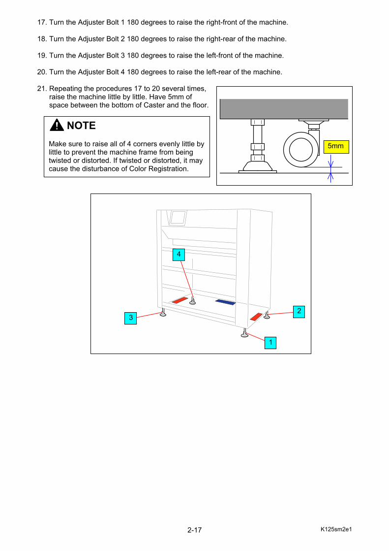
17. Turn the Adjuster Bolt 1 180 degrees to raise the right-front of the machine. 18. Turn the Adjuster Bolt 2 180 degrees to raise the right-rear of the machine. 19. Turn the Adjuster Bolt 3 180 degrees to raise the left-front of the machine. 20. Turn the Adjuster Bolt 4 180 degrees to raise the left-rear of the machine. 21. Repeating the procedures 17 to 20 several times, raise the machine little by little. Have 5mm of space between the bottom of Caster and the floor.
NOTE Make sure to raise all of 4 corners evenly little by little to prevent the machine frame from being twisted or distorted. If twisted or distorted, it may cause the disturbance of Color Registration.
3
4
1
2
5mm
K125sm2e1 2-18
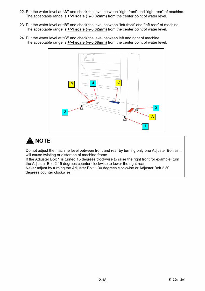
22. Put the water level at “A” and check the level between “right front” and “right rear” of machine. The acceptable range is +/-1 scale (+/-0.02mm) from the center point of water level. 23. Put the water level at “B” and check the level between “left front” and “left rear” of machine. The acceptable range is +/-1 scale (+/-0.02mm) from the center point of water level. 24. Put the water level at “C” and check the level between left and right of machine. The acceptable range is +/-4 scale (+/-0.08mm) from the center point of water level.
NOTE Do not adjust the machine level between front and rear by turning only one Adjuster Bolt as it will cause twisting or distortion of machine frame. If the Adjuster Bolt 1 is turned 15 degrees clockwise to raise the right front for example, turn the Adjuster Bolt 2 15 degrees counter clockwise to lower the right rear. Never adjust by turning the Adjuster Bolt 1 30 degrees clockwise or Adjuster Bolt 2 30 degrees counter clockwise.
A
1
2
B
3
4 C
K125sm2e1 2-19
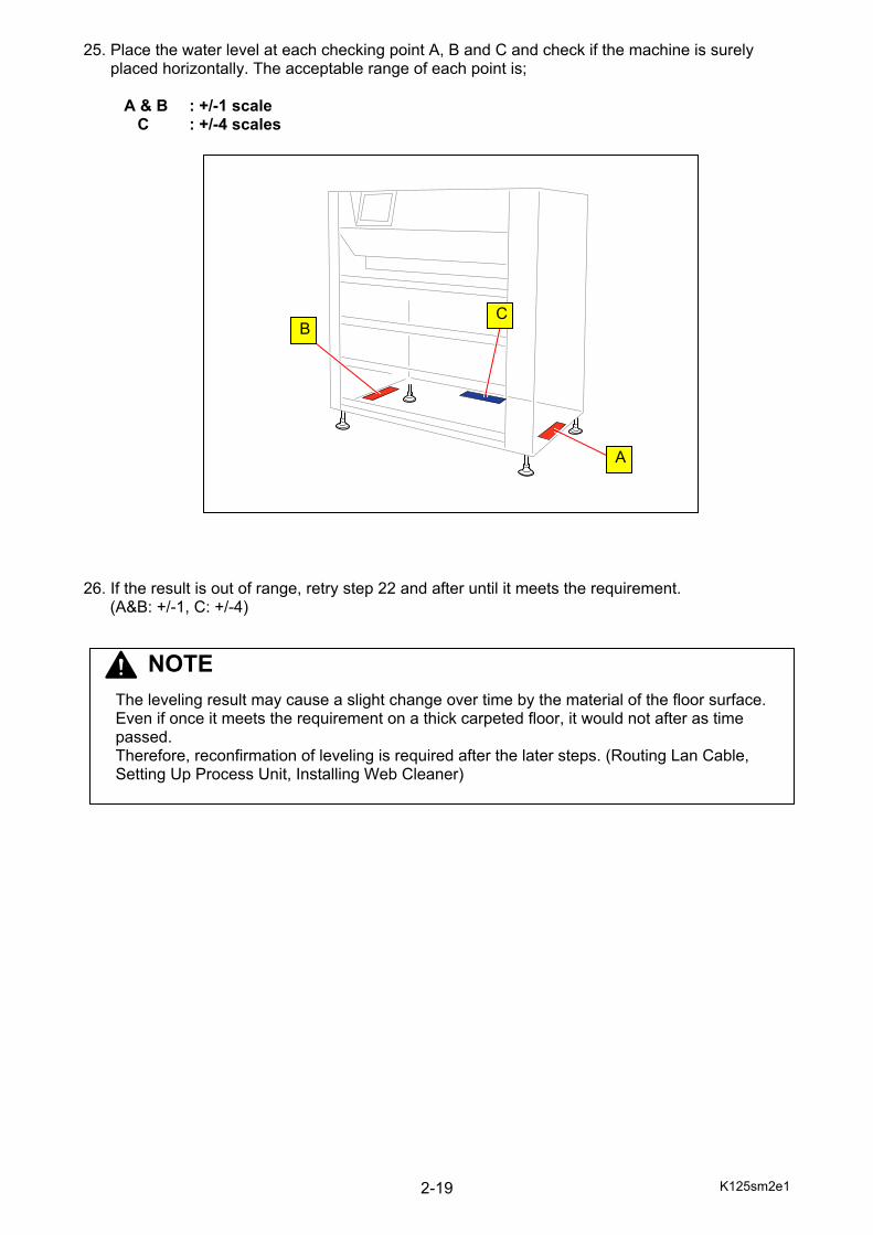
25. Place the water level at each checking point A, B and C and check if the machine is surely placed horizontally. The acceptable range of each point is;
A & B : +/-1 scale C : +/-4 scales 26. If the result is out of range, retry step 22 and after until it meets the requirement.
(A&B: +/-1, C: +/-4)
C
A
B
NOTE The leveling result may cause a slight change over time by the material of the floor surface. Even if once it meets the requirement on a thick carpeted floor, it would not after as time passed. Therefore, reconfirmation of leveling is required after the later steps. (Routing Lan Cable, Setting Up Process Unit, Installing Web Cleaner)
K125sm2e1 2-20
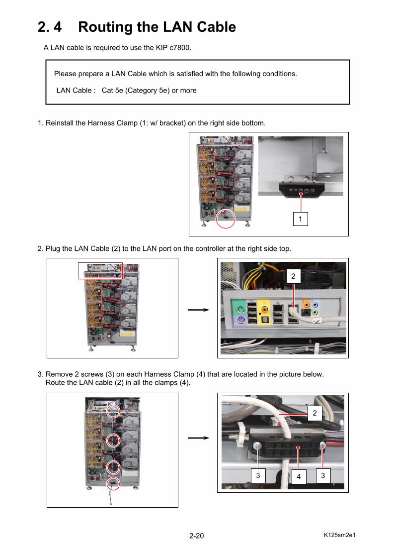
2. 4 Routing the LAN Cable A LAN cable is required to use the KIP c7800. 1. Reinstall the Harness Clamp (1: w/ bracket) on the right side bottom. 2. Plug the LAN Cable (2) to the LAN port on the controller at the right side top. 3. Remove 2 screws (3) on each Harness Clamp (4) that are located in the picture below.
Route the LAN cable (2) in all the clamps (4).
Please prepare a LAN Cable which is satisfied with the following conditions.
LAN Cable : Cat 5e (Category 5e) or more
2
1
3 34
2
K125sm2e1 2-21
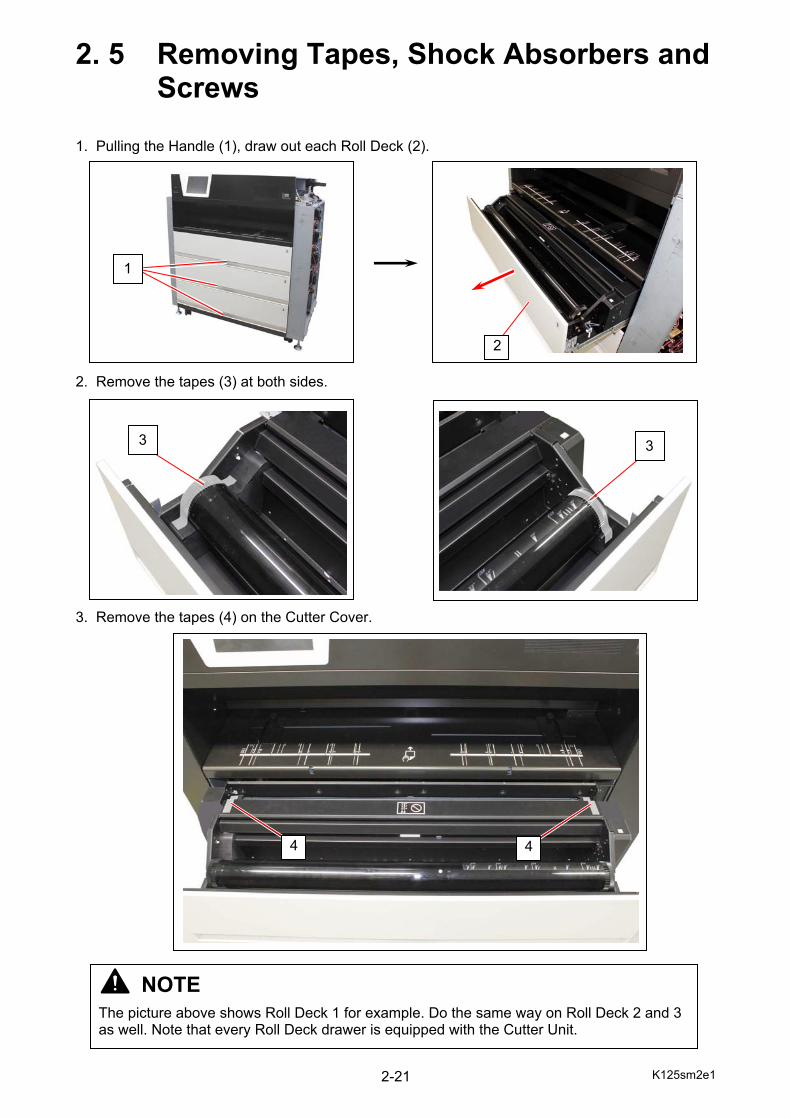
2. 5 Removing Tapes, Shock Absorbers and Screws 1. Pulling the Handle (1), draw out each Roll Deck (2). 2. Remove the tapes (3) at both sides. 3. Remove the tapes (4) on the Cutter Cover.
3 3
4 4
NOTE
The picture above shows Roll Deck 1 for example. Do the same way on Roll Deck 2 and 3 as well. Note that every Roll Deck drawer is equipped with the Cutter Unit.
1
2
K125sm2e1 2-22
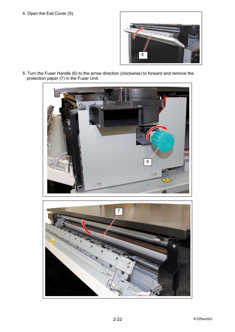
4. Open the Exit Cover (5). 5. Turn the Fuser Handle (6) to the arrow direction (clockwise) to forward and remove the
protection paper (7) in the Fuser Unit.
5
7
6
K125sm2e1 2-23
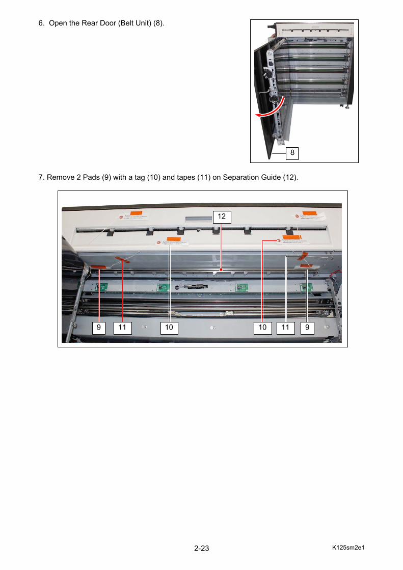
6. Open the Rear Door (Belt Unit) (8). 7. Remove 2 Pads (9) with a tag (10) and tapes (11) on Separation Guide (12).
8
9 9
12
11 1011 10
K125sm2e1 2-24
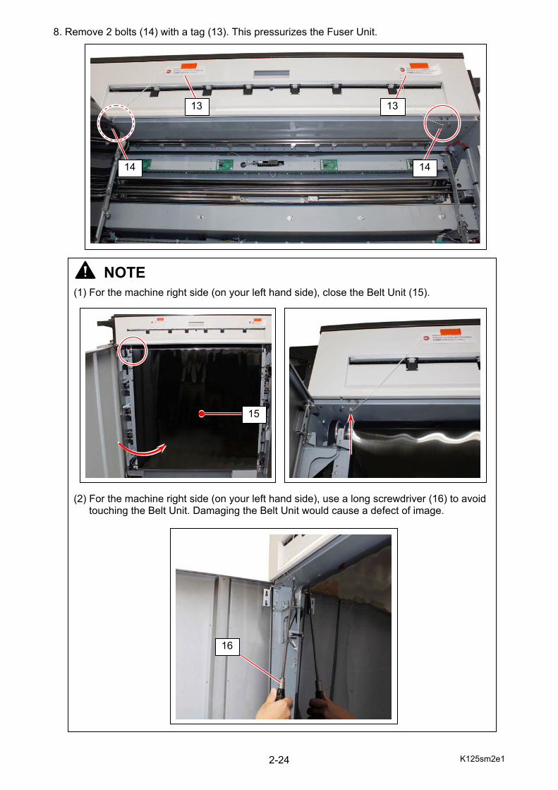
8. Remove 2 bolts (14) with a tag (13). This pressurizes the Fuser Unit.
13
14 14
NOTE
(1) For the machine right side (on your left hand side), close the Belt Unit (15). (2) For the machine right side (on your left hand side), use a long screwdriver (16) to avoid
touching the Belt Unit. Damaging the Belt Unit would cause a defect of image.
15
13
16
K125sm2e1 2-25
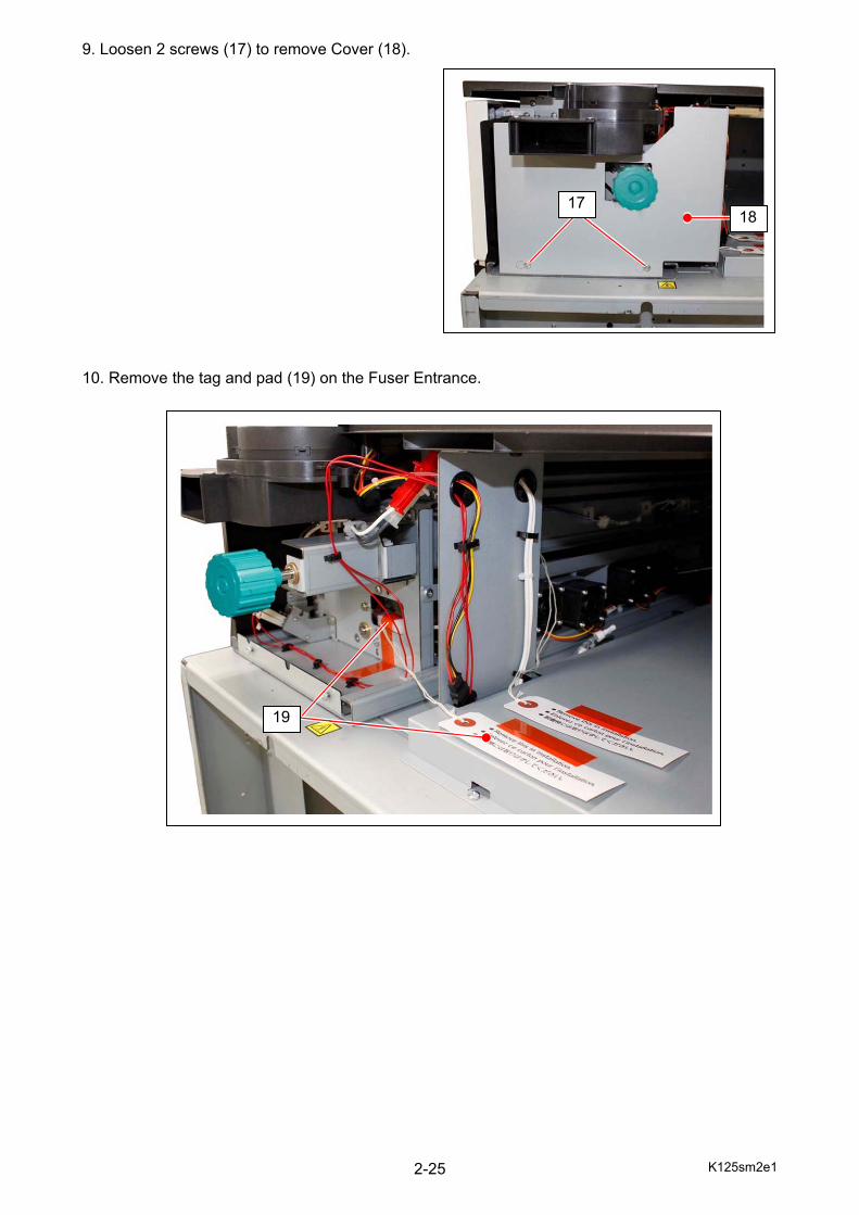
9. Loosen 2 screws (17) to remove Cover (18). 10. Remove the tag and pad (19) on the Fuser Entrance.
1718
19
K125sm2e1 2-26
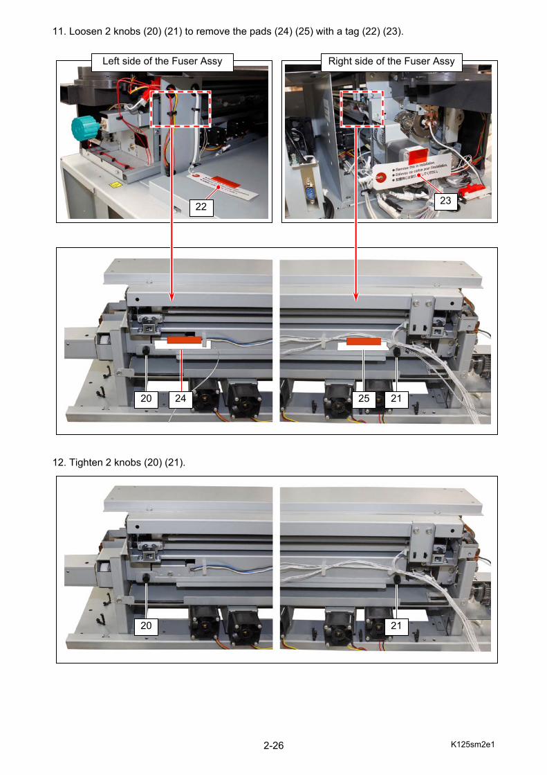
11. Loosen 2 knobs (20) (21) to remove the pads (24) (25) with a tag (22) (23).
12. Tighten 2 knobs (20) (21).
23
Right side of the Fuser Assy
21 2524 20
21 20
22
Left side of the Fuser Assy
K125sm2e1 2-27
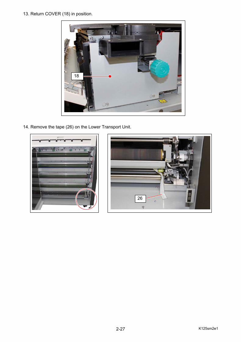
13. Return COVER (18) in position. 14. Remove the tape (26) on the Lower Transport Unit.
18
26
K125sm2e1 2-28
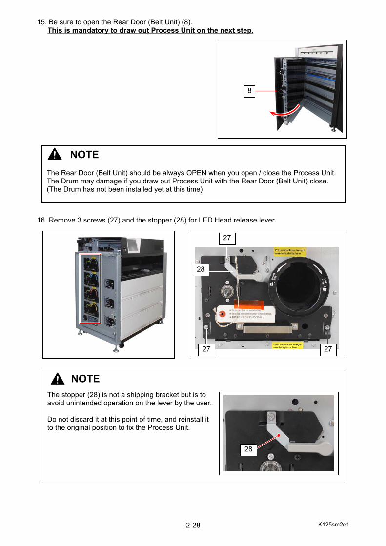
15. Be sure to open the Rear Door (Belt Unit) (8). This is mandatory to draw out Process Unit on the next step.
16. Remove 3 screws (27) and the stopper (28) for LED Head release lever.
NOTE The Rear Door (Belt Unit) should be always OPEN when you open / close the Process Unit. The Drum may damage if you draw out Process Unit with the Rear Door (Belt Unit) close. (The Drum has not been installed yet at this time)
8
NOTE
The stopper (28) is not a shipping bracket but is to avoid unintended operation on the lever by the user. Do not discard it at this point of time, and reinstall it to the original position to fix the Process Unit.
28
27 27
27
28
K125sm2e1 2-29
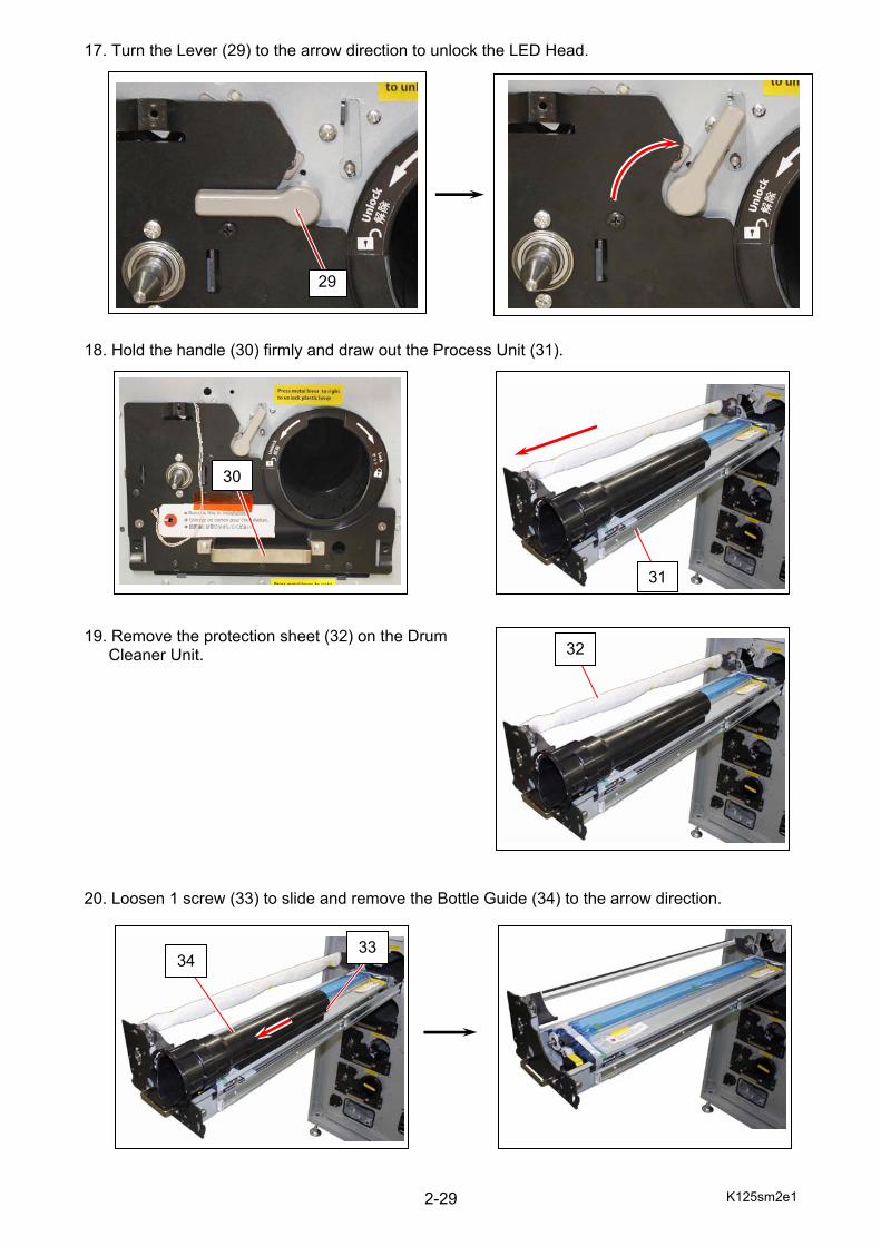
17. Turn the Lever (29) to the arrow direction to unlock the LED Head. 18. Hold the handle (30) firmly and draw out the Process Unit (31).
19. Remove the protection sheet (32) on the Drum
Cleaner Unit. 20. Loosen 1 screw (33) to slide and remove the Bottle Guide (34) to the arrow direction.
29
31
32
3334
30
K125sm2e1 2-30
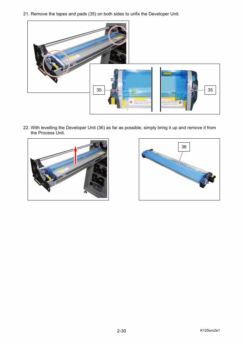
21. Remove the tapes and pads (35) on both sides to unfix the Developer Unit. 22. With levelling the Developer Unit (36) as far as possible, simply bring it up and remove it from the Process Unit.
3535
36

K125sm2e1 2-31
2. 6 Setting up the Process Unit (Developer, Cleaner, Drum)
2. 6. 1 Setting up the Developer Unit 1. Remove the protection film (1), and the sealing tape (2) on the Toner Supply Hole. 2. Remove 2 tagged screws (3). These are not reused any more.
This step is important to pressurize Developer Roller with Blade Roller.
NOTE The 3rd Process Unit (Black) will be set up in this section as an example. Please setup other 3 Process Units in the same way.
1
2
3 3
K125sm2e1 2-32
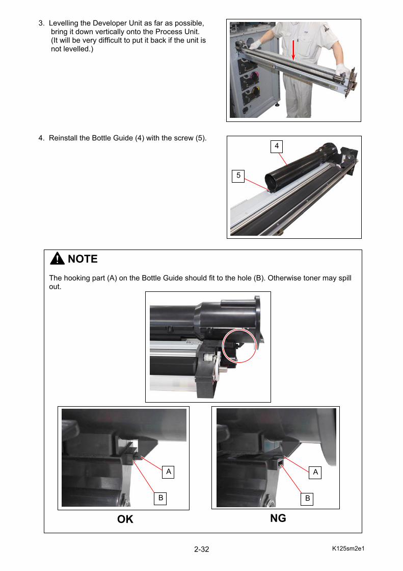
3. Levelling the Developer Unit as far as possible, bring it down vertically onto the Process Unit. (It will be very difficult to put it back if the unit is not levelled.)
4. Reinstall the Bottle Guide (4) with the screw (5).
5
4
NOTE The hooking part (A) on the Bottle Guide should fit to the hole (B). Otherwise toner may spill out.
OK
A
B
A
B
NG

K125sm2e1 2-33
2. 6. 2 Applying the toner to the Cleaning Blade 1. Loosen the screw (1) to release the Drum Stopper (2) to the arrow direction. 2. With sliding the Drum Cleaner (3) to the arrow direction (A), fully turn it to the arrow direction (B).
NOTE (1) Cleaning Blade has to be applied with the toner before installing the Drum. Otherwise the Drum or the Cleaning Blade may be damaged as the Cleaning Blade will be turned over by the friction. (2) Please take out some toner from each Toner Cartridge and apply it onto the Cleaning Blade. (3) Toner color must match with the target color of process unit. (When the process unit is for magenta, apply magenta toner. Other colors can not be used.)
3
1
2
K125sm2e1 2-34
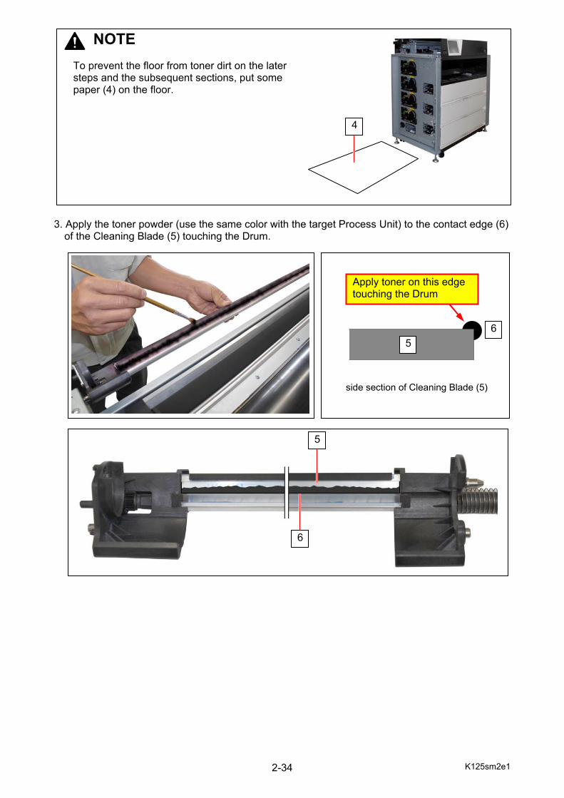
3. Apply the toner powder (use the same color with the target Process Unit) to the contact edge (6)
of the Cleaning Blade (5) touching the Drum.
5
5 6
Apply toner on this edge touching the Drum
6
5
side section of Cleaning Blade (5)
NOTE
To prevent the floor from toner dirt on the later steps and the subsequent sections, put some paper (4) on the floor.
4
K125sm2e1 2-35
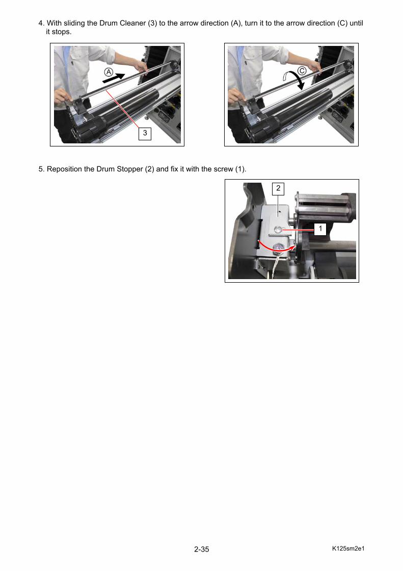
4. With sliding the Drum Cleaner (3) to the arrow direction (A), turn it to the arrow direction (C) until it stops. 5. Reposition the Drum Stopper (2) and fix it with the screw (1).
1
2
3
K125sm2e1 2-36
2. 6. 3 Installing the Drum 1. Be sure to open the Drum Cleaner (1). 2. Place the Drum (2) on to the Drum Cleaner.
The gear (3) should be located on the left of the machine.
3
1
2
3
NOTE
Every container of the Drum has a “color” indication of C, M, Y, and K. Install the Drum in the Process Unit accordingly. This section shows the procedure on Black for example, with using the Drum in the container with K (black).
K125sm2e1 2-37
3. Hold the metal areas on both ends of the Drum (Avoid the green surface), rotate it one revolution. This will match the Cleaning Blade with the Drum surface. 4. Push the Drum to the arrow direction. (machine left, the gear (3) side)
NOTE The toner on the edge of Blade is not enough if you feel it hard to rotate the Drum by hand. Apply more toner in this case.
NOTE If the Drum is not moved enough, improper gear engagement with Developer Unit may happen on the next step.
3
K125sm2e1 2-38
5. Hold both ends of the Drum and the Drum Cleaner together. Keep them holding and carefully turn the Drum to the arrow direction.
NOTE The right side gear (4) should engage with the gear in the Developer Unit (5).
4
5
K125sm2e1 2-39
6. With pushing the lever (8) to the arrow direction (outward), pull and remove the Stopper Bolt (7) with a tag (6).
6
7
8
NOTE
The Stopper Bolt (7) will be reused for dismounting the Drum. Keep it for future field maintenance.
K125sm2e1 2-40
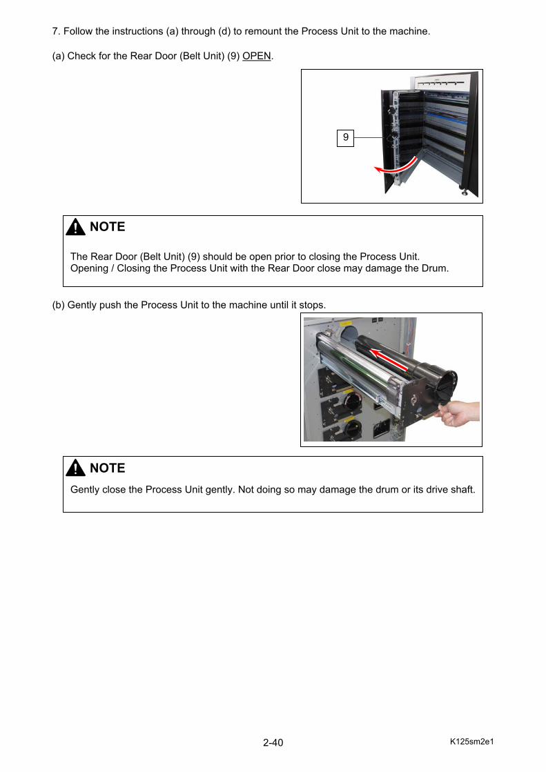
7. Follow the instructions (a) through (d) to remount the Process Unit to the machine. (a) Check for the Rear Door (Belt Unit) (9) OPEN.
(b) Gently push the Process Unit to the machine until it stops.
NOTE
The Rear Door (Belt Unit) (9) should be open prior to closing the Process Unit. Opening / Closing the Process Unit with the Rear Door close may damage the Drum.
9
NOTE
Gently close the Process Unit gently. Not doing so may damage the drum or its drive shaft.
K125sm2e1 2-41
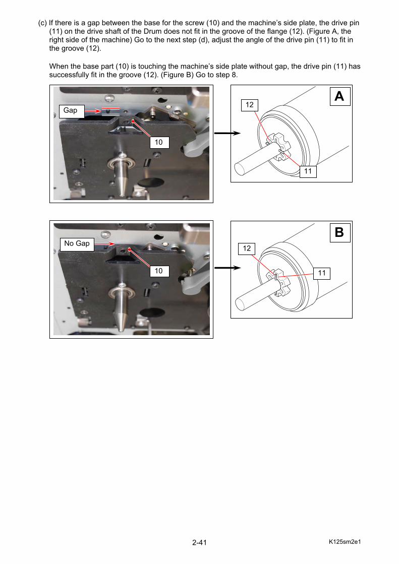
(c) If there is a gap between the base for the screw (10) and the machine’s side plate, the drive pin (11) on the drive shaft of the Drum does not fit in the groove of the flange (12). (Figure A, the right side of the machine) Go to the next step (d), adjust the angle of the drive pin (11) to fit in the groove (12). When the base part (10) is touching the machine’s side plate without gap, the drive pin (11) has successfully fit in the groove (12). (Figure B) Go to step 8.
Gap
10
A
12
B
No Gap
10 11
12
11
K125sm2e1 2-42
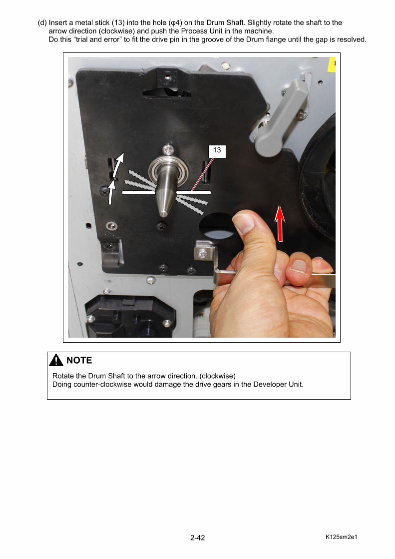
(d) Insert a metal stick (13) into the hole (φ4) on the Drum Shaft. Slightly rotate the shaft to the arrow direction (clockwise) and push the Process Unit in the machine. Do this “trial and error” to fit the drive pin in the groove of the Drum flange until the gap is resolved.
13
NOTE
Rotate the Drum Shaft to the arrow direction. (clockwise) Doing counter-clockwise would damage the drive gears in the Developer Unit.

K125sm2e1 2-43
8. Follow the instructions (a) through (c) to return the LED Head release lever (14).
(a) Put your finger on the LED Head release lever (14) and turn the lock lever (15) to the arrow direction.
(b) The LED Head release lever (14) is now unlocked and can move to the arrow direction.
(c) Gently turn the LED Head release lever (14) to its home position.
14
14
15
14
14 14
K125sm2e1 2-44
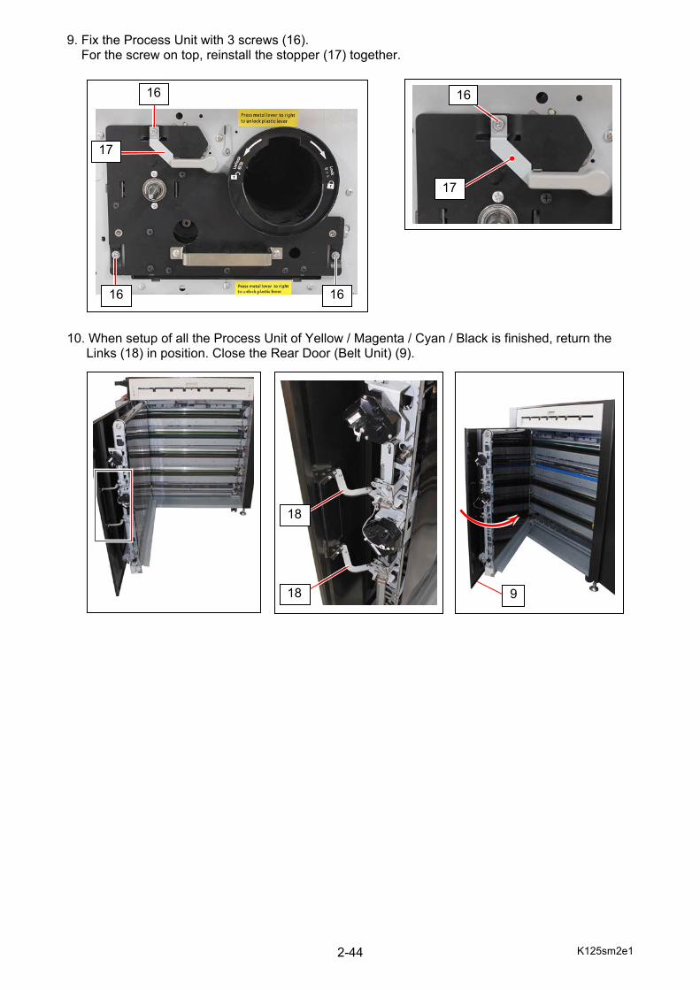
9. Fix the Process Unit with 3 screws (16). For the screw on top, reinstall the stopper (17) together.
10. When setup of all the Process Unit of Yellow / Magenta / Cyan / Black is finished, return the
Links (18) in position. Close the Rear Door (Belt Unit) (9).
16 16
16
17
17
16
9
18
18
K125sm2e1 2-45
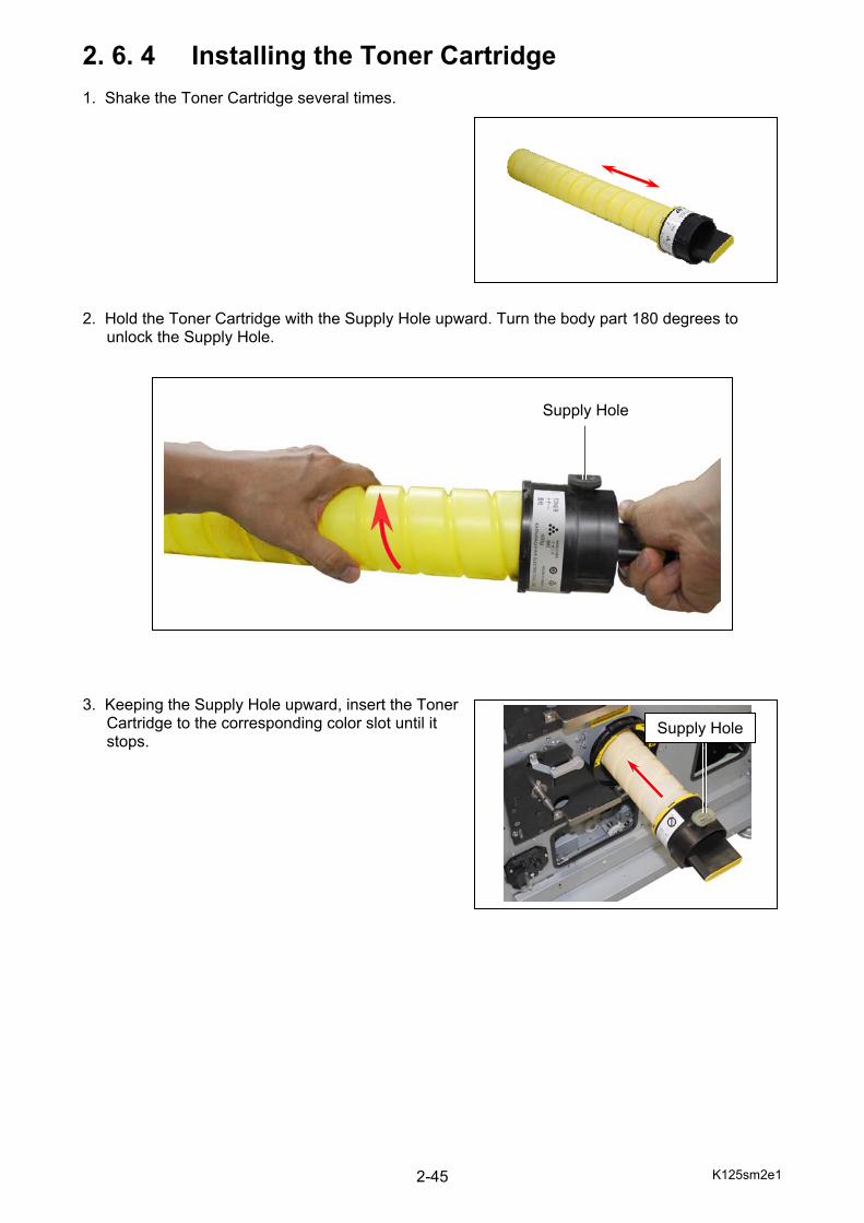
2. 6. 4 Installing the Toner Cartridge 1. Shake the Toner Cartridge several times. 2. Hold the Toner Cartridge with the Supply Hole upward. Turn the body part 180 degrees to
unlock the Supply Hole. 3. Keeping the Supply Hole upward, insert the Toner
Cartridge to the corresponding color slot until it stops.
Supply Hole
Supply Hole
K125sm2e1 2-46
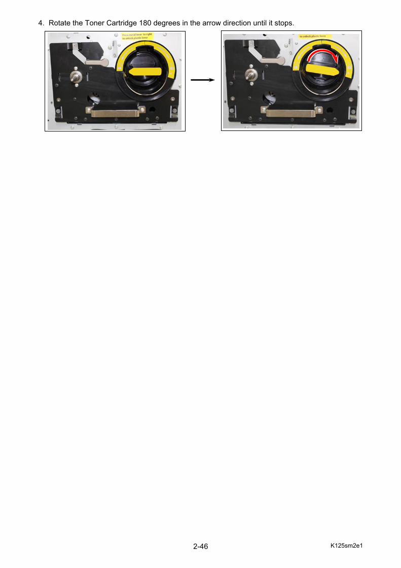
4. Rotate the Toner Cartridge 180 degrees in the arrow direction until it stops.

K125sm2e1 2-47
2. 7 Installing the Web Cleaner 1. Open the Exit Cover (1). 2. Hold the knobs on both sides (2), draw out the Web Unit (3) f until it stops.
Lift the back of the Web Unit up to escape the stopper to remove it from the machine.
NOTE
Wear groves (rubber or plastic) when setting up Web Cleaner.
1
3
3 2

K125sm2e1 2-48
3. Install the thicker roll of Web (4) to the shaft’s pin (5) on the back (inner) of your right hand side. Fit the pin (5) to the notch (6) on the core bar of the roll (4).
NOTE Install the Web in the correct direction noting its winding direction.
5
4
5
6
Knob
K125sm2e1 2-49
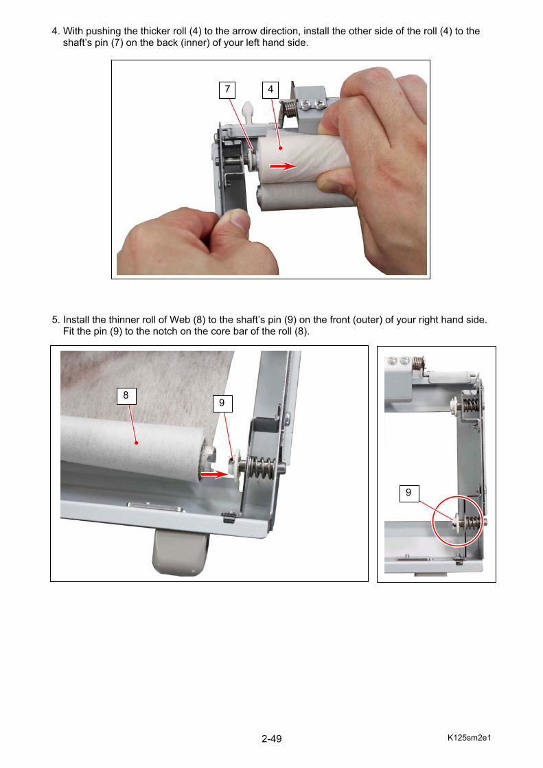
4. With pushing the thicker roll (4) to the arrow direction, install the other side of the roll (4) to the shaft’s pin (7) on the back (inner) of your left hand side.
5. Install the thinner roll of Web (8) to the shaft’s pin (9) on the front (outer) of your right hand side.
Fit the pin (9) to the notch on the core bar of the roll (8).
8
7 4
9
9

K125sm2e1 2-50
6. With pushing the thinner roll (8) to the arrow direction, install the other side of the roll (8) to the shaft’s pin (10) on the front (outer) of your left hand side. 7. Turn the gear (11) to remove slack on the Web.
11
10 8
K125sm2e1 2-51
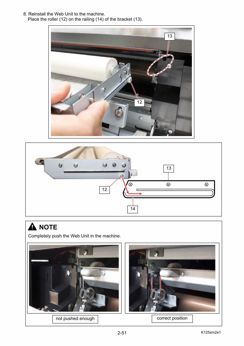
8. Reinstall the Web Unit to the machine. Place the roller (12) on the railing (14) of the bracket (13).
12
13
NOTE
Completely push the Web Unit in the machine.
not pushed enough correct position
14
13
12
K125sm2e1 2-52
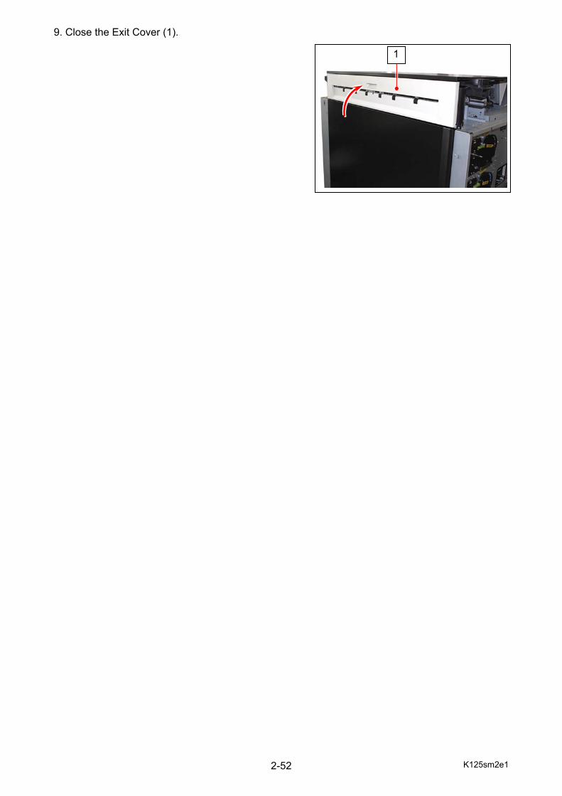
9. Close the Exit Cover (1).
1
K125sm2e1 2-53
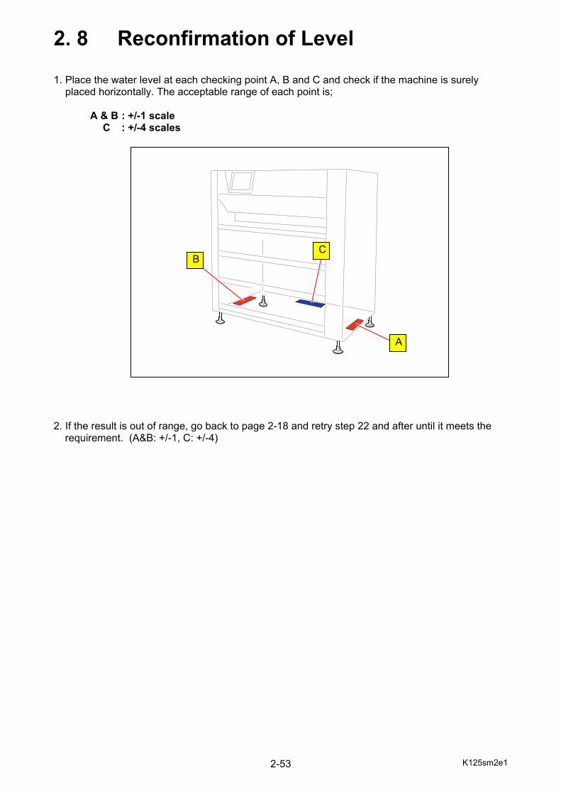
2. 8 Reconfirmation of Level 1. Place the water level at each checking point A, B and C and check if the machine is surely placed horizontally. The acceptable range of each point is;
A & B : +/-1 scale C : +/-4 scales 2. If the result is out of range, go back to page 2-18 and retry step 22 and after until it meets the
requirement. (A&B: +/-1, C: +/-4)
C
A
B

K125sm2e1 2-54
3. Reinstall the Right Side Cover (1), Door Frame (2), and Left Side Door (3). 4. Reinstall the front face (5) to the Waste Toner Case.
Reinstall the Waste Toner Box (6) in the Waste Toner Case.
NOTE Reinstall the Ground Lead (4).
4
5
6
1
3 2
NOTE Install the Waste Toner Box (6) so that the sensor window (7) comes to the machine’s center side.
6
7
K125sm2e1 2-55
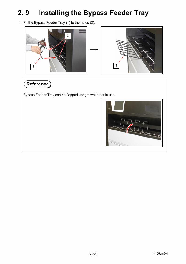
2. 9 Installing the Bypass Feeder Tray 1. Fit the Bypass Feeder Tray (1) to the holes (2).
Reference
Bypass Feeder Tray can be flapped upright when not in use.
2
1 1
K125sm2e2 2-56
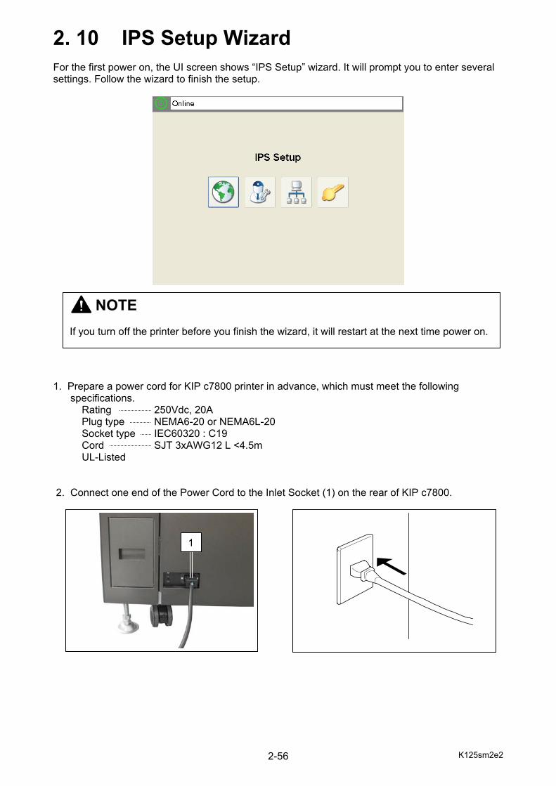
2. 10 IPS Setup Wizard For the first power on, the UI screen shows “IPS Setup” wizard. It will prompt you to enter several settings. Follow the wizard to finish the setup. 1. Prepare a power cord for KIP c7800 printer in advance, which must meet the following specifications. Rating 250Vdc, 20A Plug type NEMA6-20 or NEMA6L-20 Socket type IEC60320 : C19 Cord SJT 3xAWG12 L <4.5m UL-Listed 2. Connect one end of the Power Cord to the Inlet Socket (1) on the rear of KIP c7800.
1
NOTE If you turn off the printer before you finish the wizard, it will restart at the next time power on.
K125sm2e2 2-57
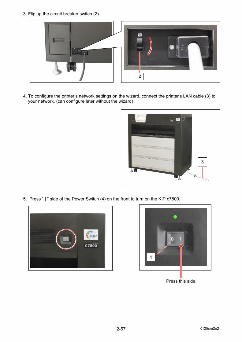
3. Flip up the circuit breaker switch (2). 4. To configure the printer’s network settings on the wizard, connect the printer’s LAN cable (3) to
your network. (can configure later without the wizard) 5. Press “ | ” side of the Power Switch (4) on the front to turn on the KIP c7800.
Press this side.
4
2
3

K125sm2e2 2-58
6. “IPS Setup” wizard is displayed in the UI screen. Press [regional settings]. 7. Select a language. 8. Set date and time, and then press [OK]. (can configure later without the wizard)
K125sm2e2 2-59
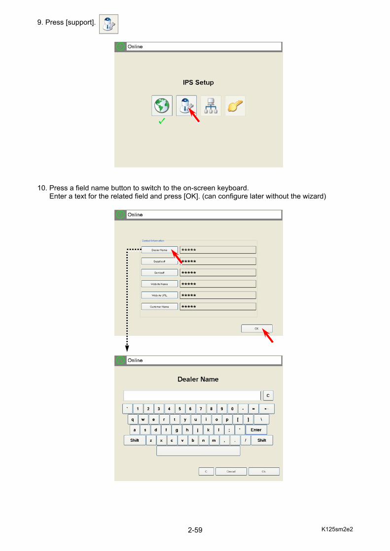
9. Press [support]. 10. Press a field name button to switch to the on-screen keyboard. Enter a text for the related field and press [OK]. (can configure later without the wizard)
K125sm2e2 2-60
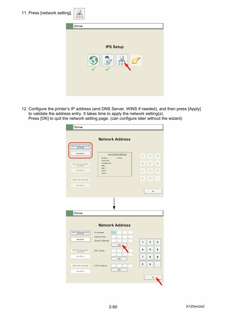
11. Press [network setting]. 12. Configure the printer’s IP address (and DNS Server, WINS if needed), and then press [Apply]
to validate the address entry. It takes time to apply the network setting(s). Press [OK] to quit the network setting page. (can configure later without the wizard)
K125sm2e2 2-61
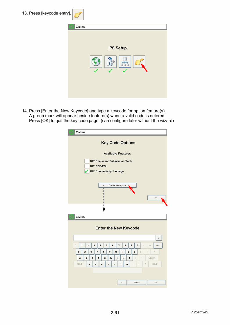
13. Press [keycode entry]. 14. Press [Enter the New Keycode] and type a keycode for option feature(s). A green mark will appear beside feature(s) when a valid code is entered. Press [OK] to quit the key code page. (can configure later without the wizard)

K125sm2e2 2-62
15. When [regional setting] [support] [network setting] [key code entry] has a green check mark, press [OK].. IPS will automatically reboot.
K125sm2e2 2-63
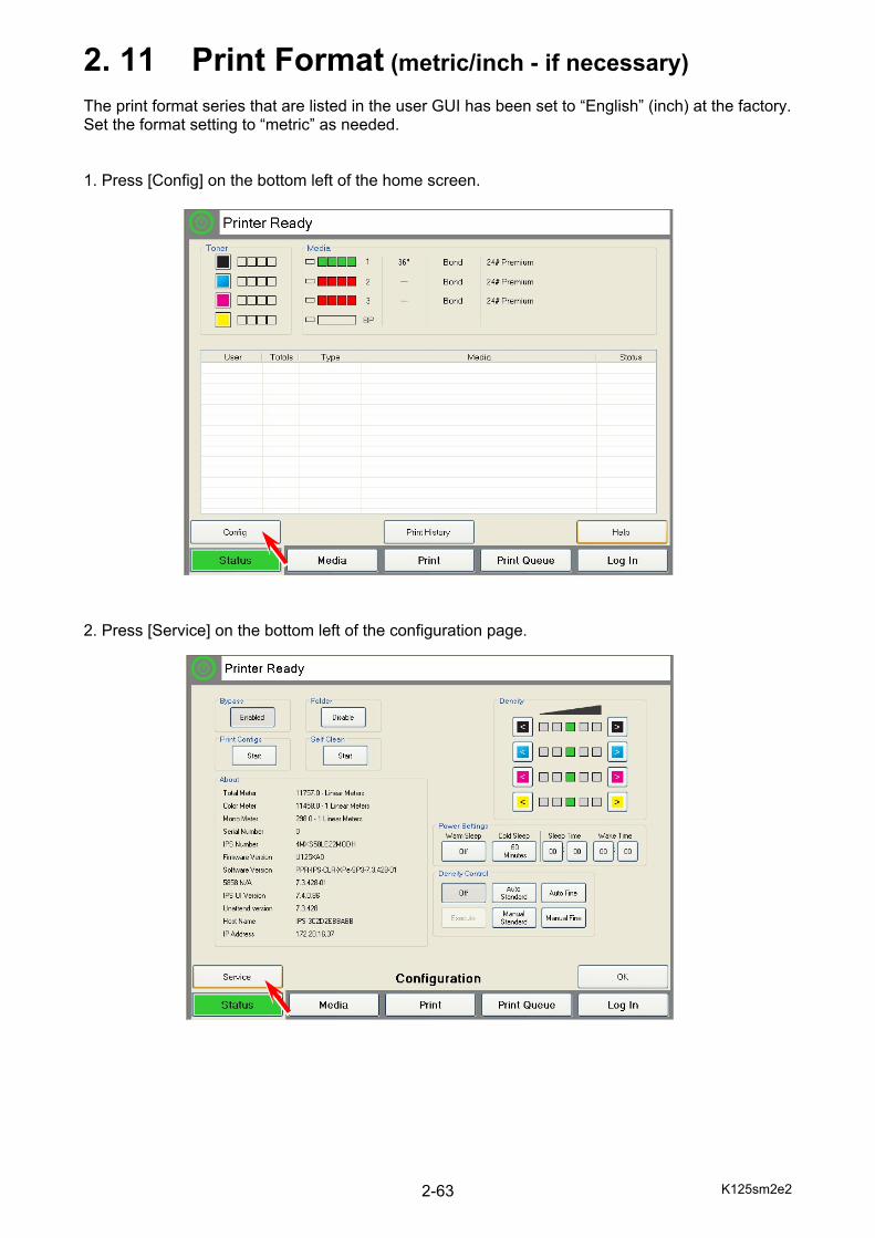
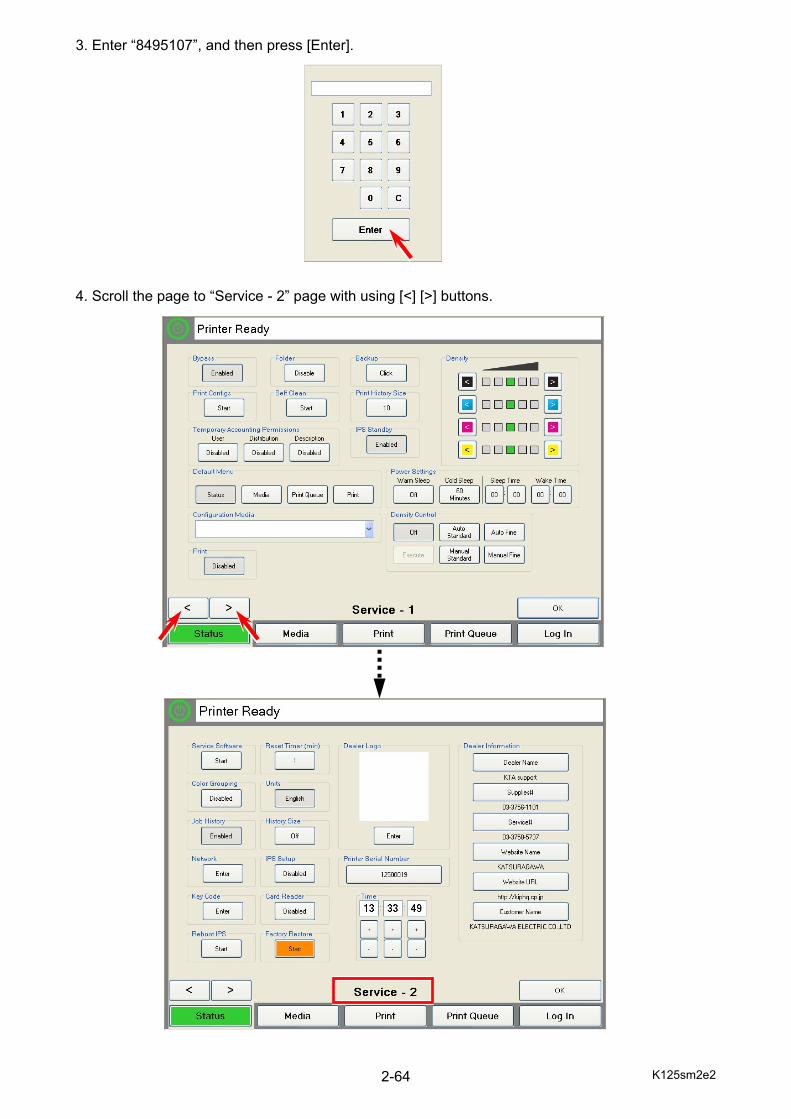
2. 11 Print Format (metric/inch - if necessary) The print format series that are listed in the user GUI has been set to “English” (inch) at the factory. Set the format setting to “metric” as needed. 1. Press [Config] on the bottom left of the home screen. 2. Press [Service] on the bottom left of the configuration page.
K125sm2e2 2-64
3. Enter “8495107”, and then press [Enter]. 4. Scroll the page to “Service - 2” page with using [<] [>] buttons.
K125sm2e2 2-65
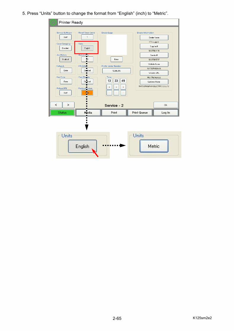
5. Press “Units” button to change the format from “English” (inch) to “Metric”.
K125sm2e2 2-66
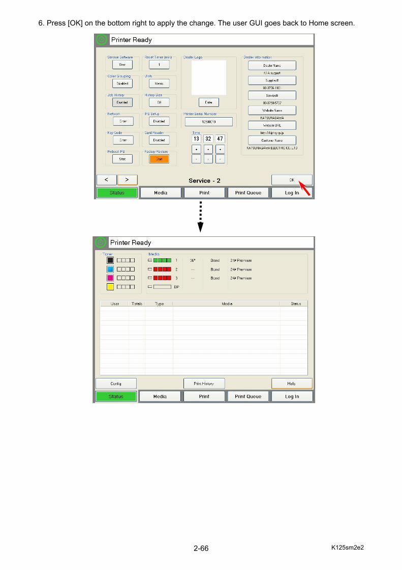
6. Press [OK] on the bottom right to apply the change. The user GUI goes back to Home screen.
K125sm2e2 2-67
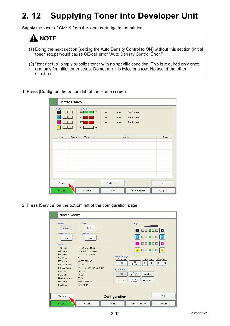
2. 12 Supplying Toner into Developer Unit Supply the toner of CMYK from the toner cartridge to the printer. 1. Press [Config] on the bottom left of the Home screen. 2. Press [Service] on the bottom left of the configuration page.
NOTE (1) Doing the next section (setting the Auto Density Control to ON) without this section (initial
toner setup) would cause CE-call error “Auto Density Control Error.” (2) “toner setup” simply supplies toner with no specific condition. This is required only once,
and only for initial toner setup. Do not run this twice in a row. No use of the other situation.

K125sm2e2 2-68
3. Enter “8495107”, and then press [Enter]. 4. Scroll the page to “Service - 2” page with using [<] [>] buttons. Press [Start] in Service Software region (top left).
K125sm2e2 2-69
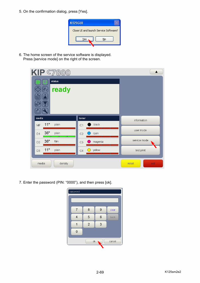
5. On the confirmation dialog, press [Yes]. 6. The home screen of the service software is displayed. Press [service mode] on the right of the screen. 7. Enter the password (PIN: “0000”), and then press [ok].
K125sm2e2 2-70
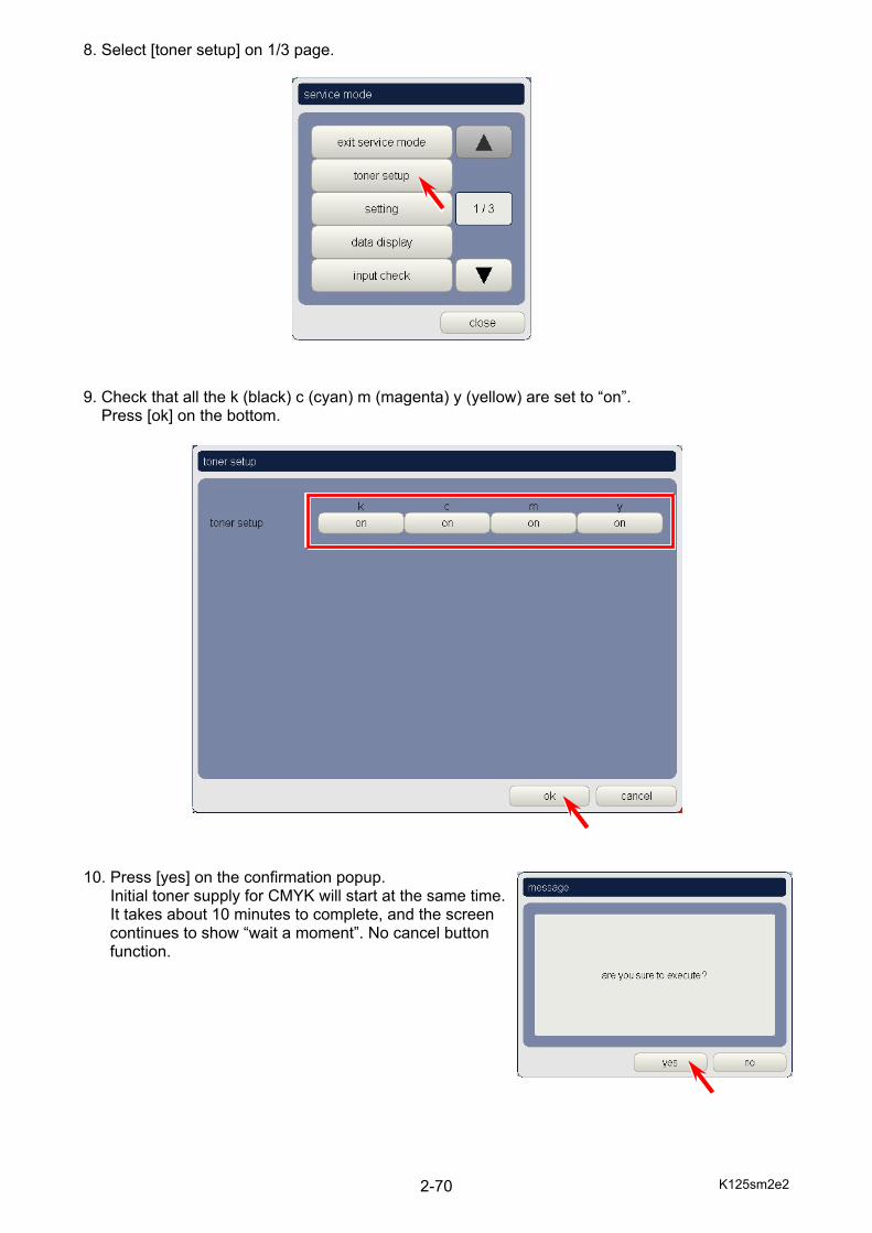
8. Select [toner setup] on 1/3 page. 9. Check that all the k (black) c (cyan) m (magenta) y (yellow) are set to “on”. Press [ok] on the bottom.
10. Press [yes] on the confirmation popup. Initial toner supply for CMYK will start at the same time. It takes about 10 minutes to complete, and the screen
continues to show “wait a moment”. No cancel button function.
K125sm2e2 2-71
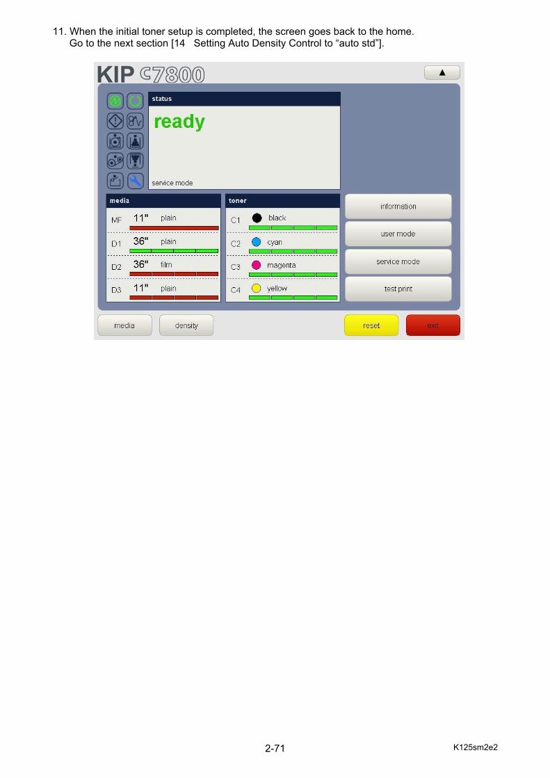
11. When the initial toner setup is completed, the screen goes back to the home. Go to the next section [14 Setting Auto Density Control to “auto std”].
K125sm2e2 2-72
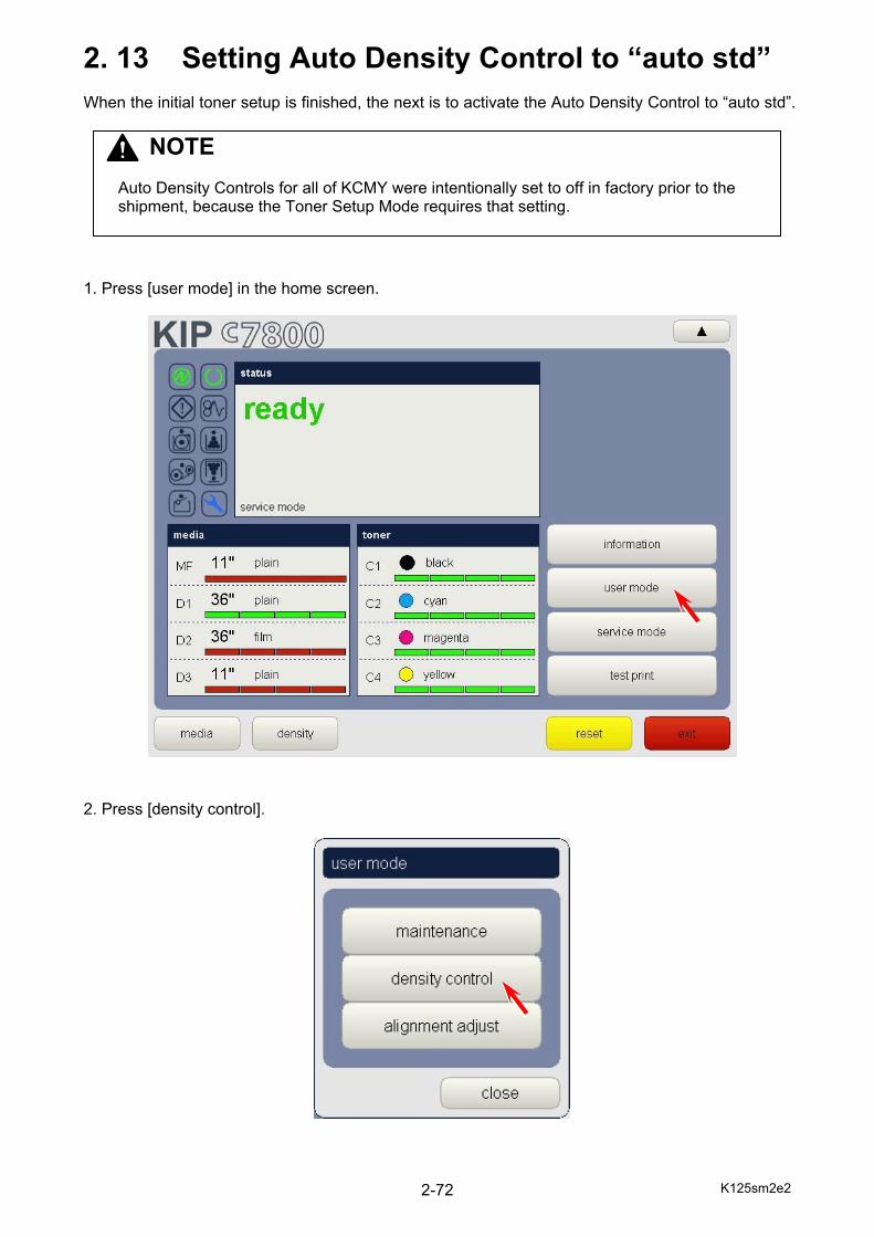
2. 13 Setting Auto Density Control to “auto std” When the initial toner setup is finished, the next is to activate the Auto Density Control to “auto std”. 1. Press [user mode] in the home screen. 2. Press [density control].
NOTE
Auto Density Controls for all of KCMY were intentionally set to off in factory prior to the shipment, because the Toner Setup Mode requires that setting.
K125sm2e2 2-73
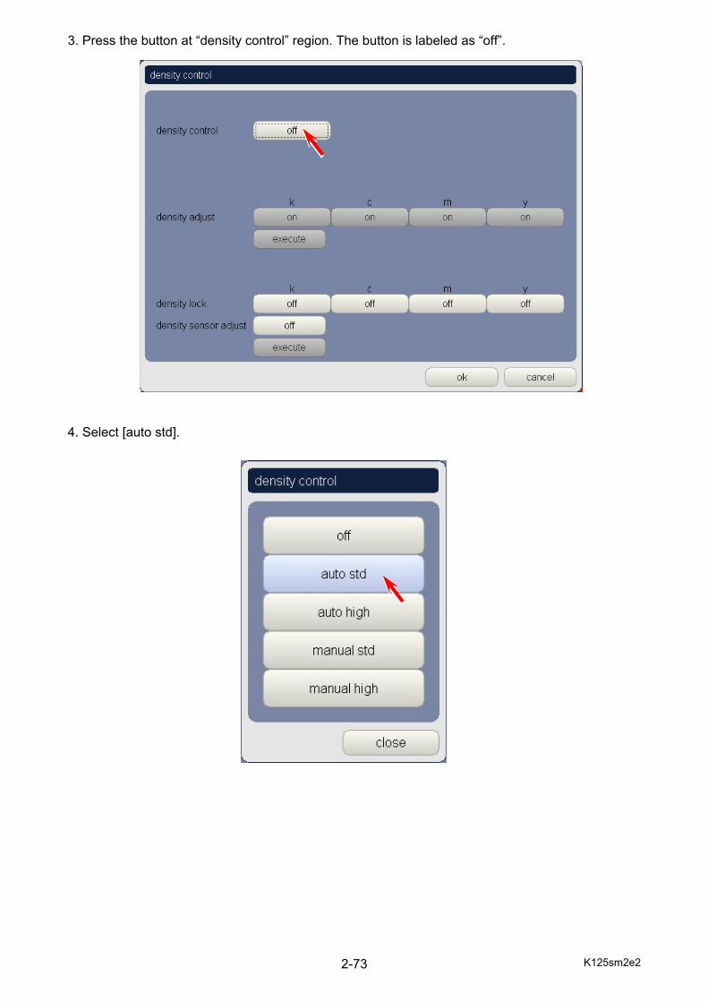
3. Press the button at “density control” region. The button is labeled as “off”. 4. Select [auto std].
K125sm2e2 2-74
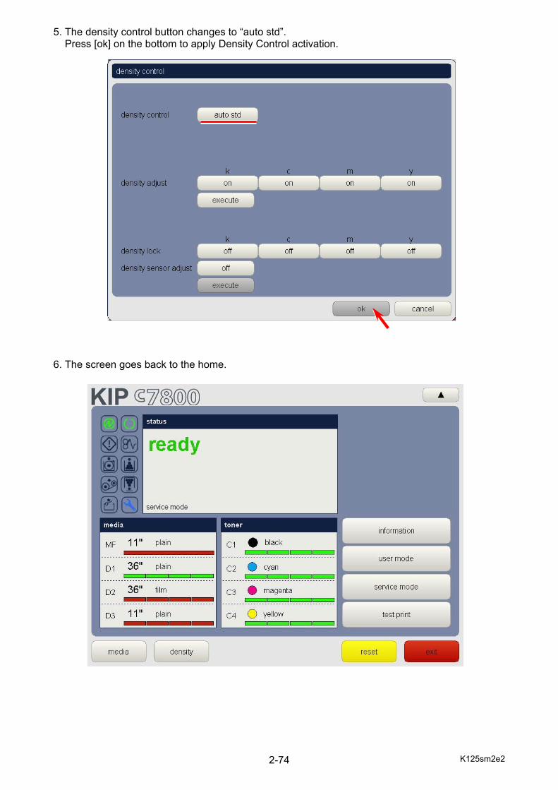
5. The density control button changes to “auto std”. Press [ok] on the bottom to apply Density Control activation. 6. The screen goes back to the home.
K125sm2e2 2-75
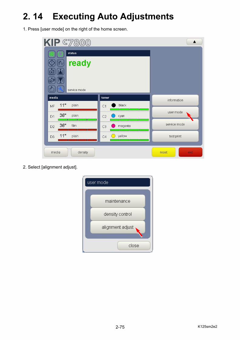
2. 14 Executing Auto Adjustments 1. Press [user mode] on the right of the home screen. 2. Select [alignment adjust].

K125sm2e2 2-76
3. Press [next] on the bottom of 1/2 page. 4. On 2/2 page, press “mode” button to recall mode selector popup.
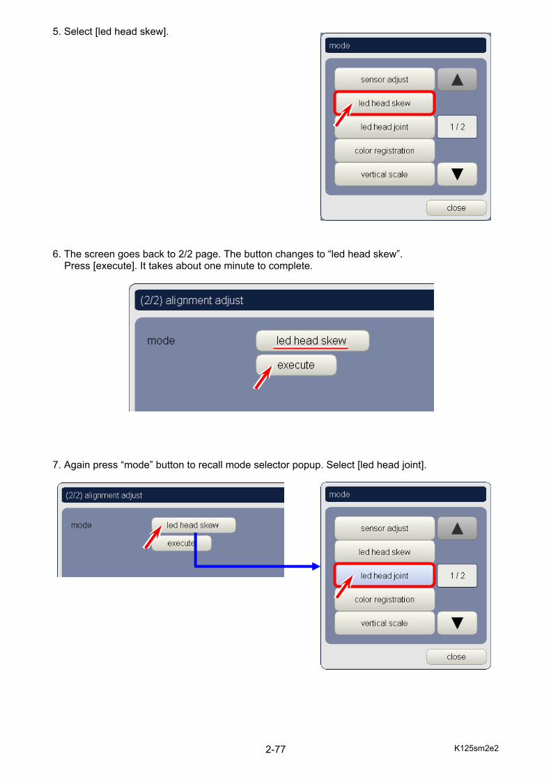
K125sm2e2 2-77
5. Select [led head skew]. 6. The screen goes back to 2/2 page. The button changes to “led head skew”.
Press [execute]. It takes about one minute to complete.
7. Again press “mode” button to recall mode selector popup. Select [led head joint].
K125sm2e2 2-78
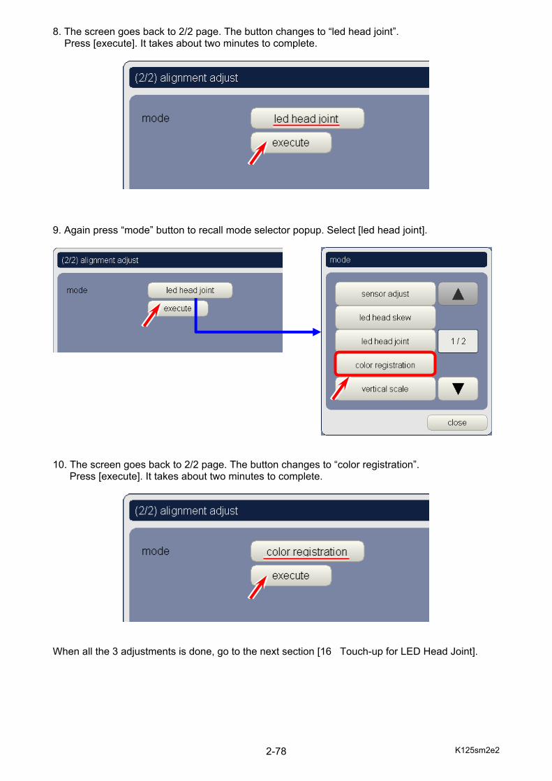
8. The screen goes back to 2/2 page. The button changes to “led head joint”. Press [execute]. It takes about two minutes to complete.
9. Again press “mode” button to recall mode selector popup. Select [led head joint].
10. The screen goes back to 2/2 page. The button changes to “color registration”.
Press [execute]. It takes about two minutes to complete.
When all the 3 adjustments is done, go to the next section [16 Touch-up for LED Head Joint].
K125sm2e2 2-79
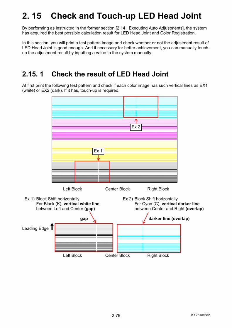
2. 15 Check and Touch-up LED Head Joint By performing as instructed in the former section [2.14 Executing Auto Adjustments], the system has acquired the best possible calculation result for LED Head Joint and Color Registration. In this section, you will print a test pattern image and check whether or not the adjustment result of LED Head Joint is good enough. And if necessary for better achievement, you can manually touch-up the adjustment result by inputting a value to the system manually.
2.15. 1 Check the result of LED Head Joint At first print the following test pattern and check if each color image has such vertical lines as EX1 (white) or EX2 (dark). If it has, touch-up is required.
Left Block Center Block Right Block Ex 1) Block Shift horizontally Ex 2) Block Shift horizontally For Black (K), vertical white line For Cyan (C), vertical darker line between Left and Center (gap) between Center and Right (overlap)
gap darker line (overlap) Leading Edge
Left Block Center Block Right Block
Ex 2
Ex 1
K125sm2e2 2-80
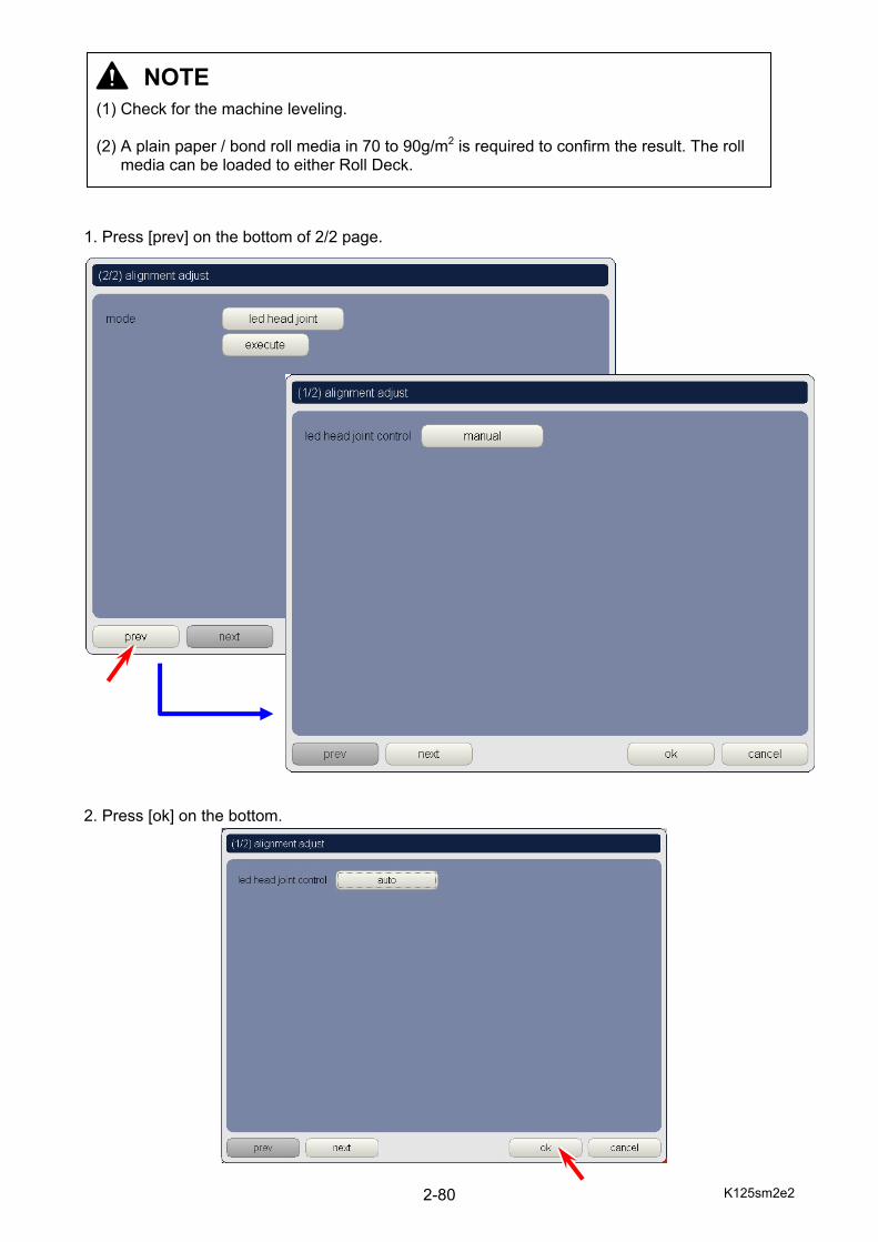
1. Press [prev] on the bottom of 2/2 page. 2. Press [ok] on the bottom.
NOTE (1) Check for the machine leveling. (2) A plain paper / bond roll media in 70 to 90g/m2 is required to confirm the result. The roll
media can be loaded to either Roll Deck.
K125sm2e2 2-81
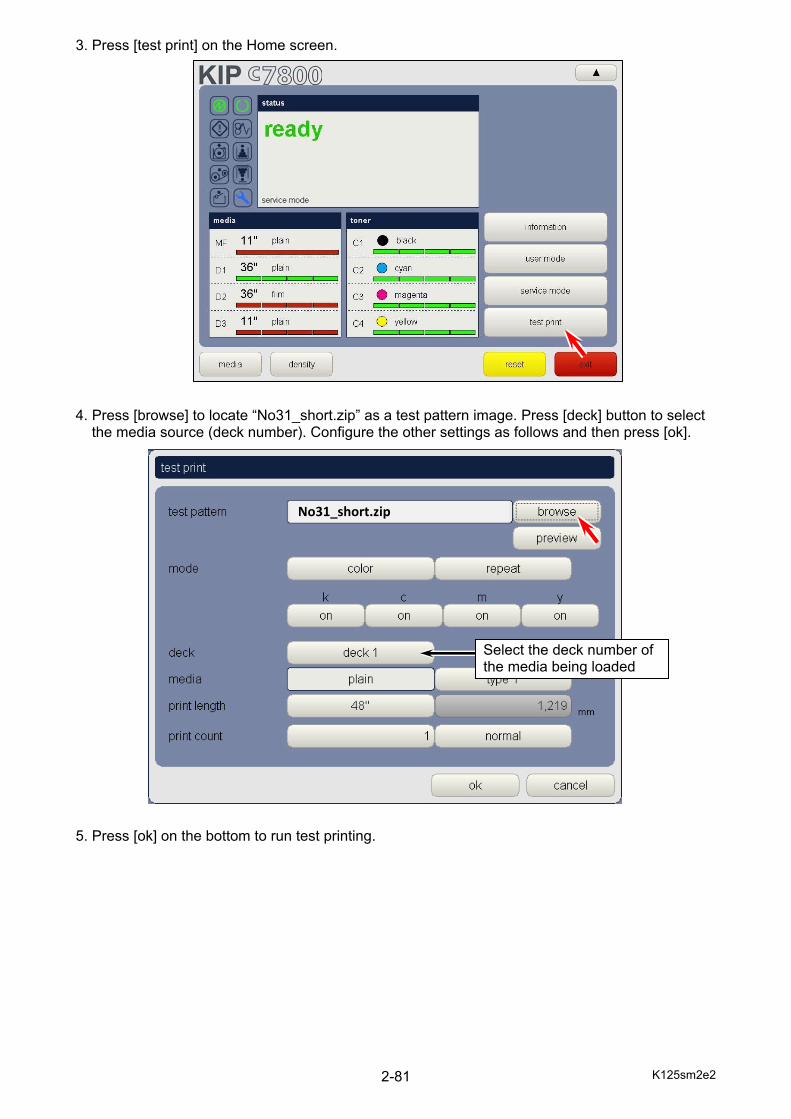
3. Press [test print] on the Home screen. 4. Press [browse] to locate “No31_short.zip” as a test pattern image. Press [deck] button to select
the media source (deck number). Configure the other settings as follows and then press [ok]. 5. Press [ok] on the bottom to run test printing.
No31_short.zip
Select the deck number of the media being loaded

K125sm2e2 2-82
6. Check for a vertical line(s) on the test print image “No31_short.zip” as shown below. If a white line or a darker line appears, go to the next [2.15.2 Touch-up LED Head Joint]. When your test print has already a satisfactory calculation for “LED Head Joint”, go to [2.16 Touch-up for Color Registration]. (Skip the next [2.15.2 Touch-up LED Head Joint].)
Left Block Center Block Right Block Ex 1) Block Shift horizontally Ex 2) Block Shift horizontally For Black (K), vertical white line For Cyan (C), vertical darker line between Left and Center (gap) between Center and Right (overlap)
gap darker line (overlap) Leading Edge
Left Block Center Block Right Block In Ex 1, you may see a vertical white line. This means that the LED Head’s neighboring Blocks do not touch each other (has a gap). To remove the gap, move the Left / Right Block close to the Center Block. A manual input for the amount of shift (pixels) can be specified.
Ex 2
Ex 1
Left Center Right Left Center Right
Left Center Right
K125sm2e2 2-83
In Ex 2, you may see a vertical darker line. This means that the LED Head’s neighboring Blocks is now overlapping each other. To remove the overlap, move the Left / Right Block away from the Center Block. A manual input for the amount of shift (pixels) can be specified.
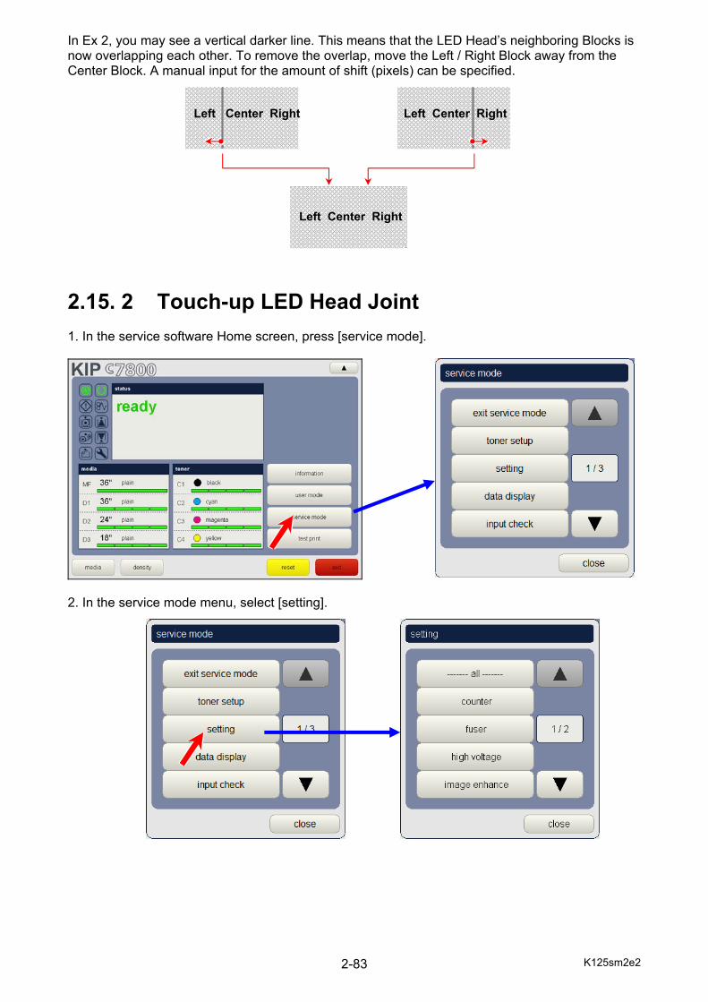
2.15. 2 Touch-up LED Head Joint 1. In the service software Home screen, press [service mode].
2. In the service mode menu, select [setting].
Left Center Right
Left Center Right Left Center Right
K125sm2e2 2-84
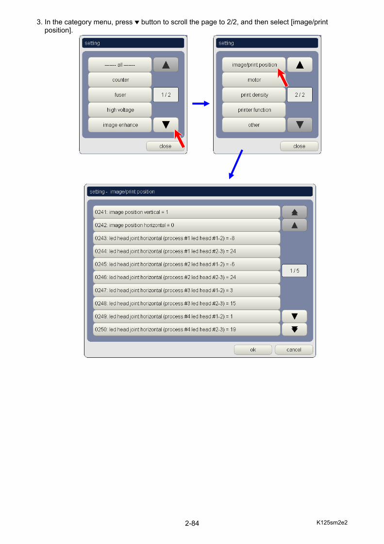
3. In the category menu, press button to scroll the page to 2/2, and then select [image/print position].
K125sm2e2 2-85
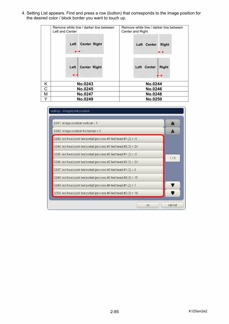
4. Setting List appears. Find and press a row (button) that corresponds to the image position for the desired color / block border you want to touch up.
Remove white line / darker line between Left and Center
Remove white line / darker line between Center and Right
K No.0243 No.0244 C No.0245 No.0246 M No.0247 No.0248 Y No.0249 No.0250
Left Center Right
Left Center Right
Left Center Right
Left Center Right
K125sm2e2 2-86
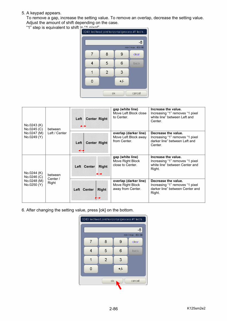
5. A keypad appears. To remove a gap, increase the setting value. To remove an overlap, decrease the setting value. Adjust the amount of shift depending on the case. “1” step is equivalent to shift in “1 pixel”.
No.0243 (K) No.0245 (C) No.0247 (M) No.0249 (Y)
between Left / Center
gap (white line)Move Left Block close to Center.
Increase the value. Increasing “1” removes “1 pixel white line” between Left and Center.
overlap (darker line)Move Left Block away from Center.
Decrease the value. Increasing “1” removes “1 pixel darker line” between Left and Center.
No.0244 (K) No.0246 (C) No.0248 (M) No.0250 (Y)
between Center / Right
gap (white line)Move Right Block close to Center.
Increase the value. Increasing “1” removes “1 pixel white line” between Center and Right.
overlap (darker line)Move Right Block away from Center.
Decrease the value. Increasing “1” removes “1 pixel darker line” between Center and Right.
6. After changing the setting value, press [ok] on the bottom.
Left Center Right
Left Center Right
Left Center Right
Left Center Right
K125sm2e2 2-87
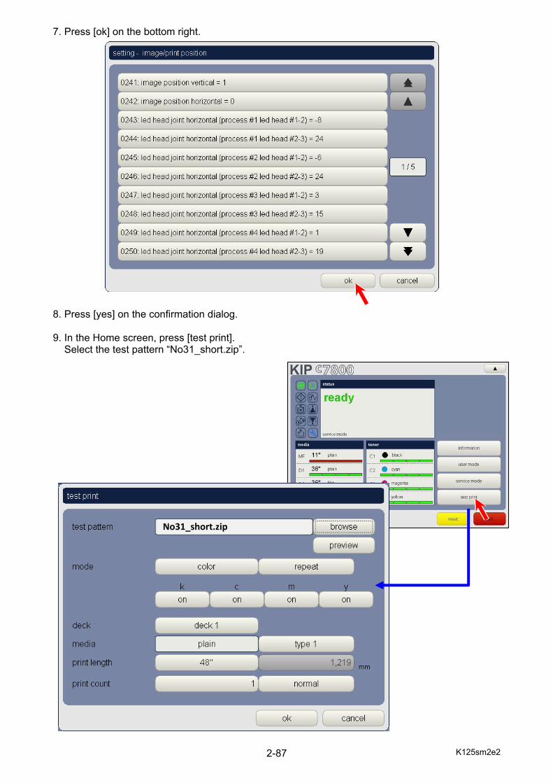
7. Press [ok] on the bottom right. 8. Press [yes] on the confirmation dialog. 9. In the Home screen, press [test print]. Select the test pattern “No31_short.zip”.
No31_short.zip

K125sm2e2 2-88
10. Press [ok] on the bottom to run test printing. 11. Confirm the touch-up result again on the test print.
Take additional touch-up in the same way of step 5 if vertical white / darker line is still seen. 12. If the touch-up result looks OK, go to the next section [2.16 Check and Touch-up Color
Registration].
NOTE After this, do not perform “led head joint” adjustment again if there is not any special reason. If you do so the result of touch-up will be overwritten by automatic adjustment.
K125sm2e2 2-89
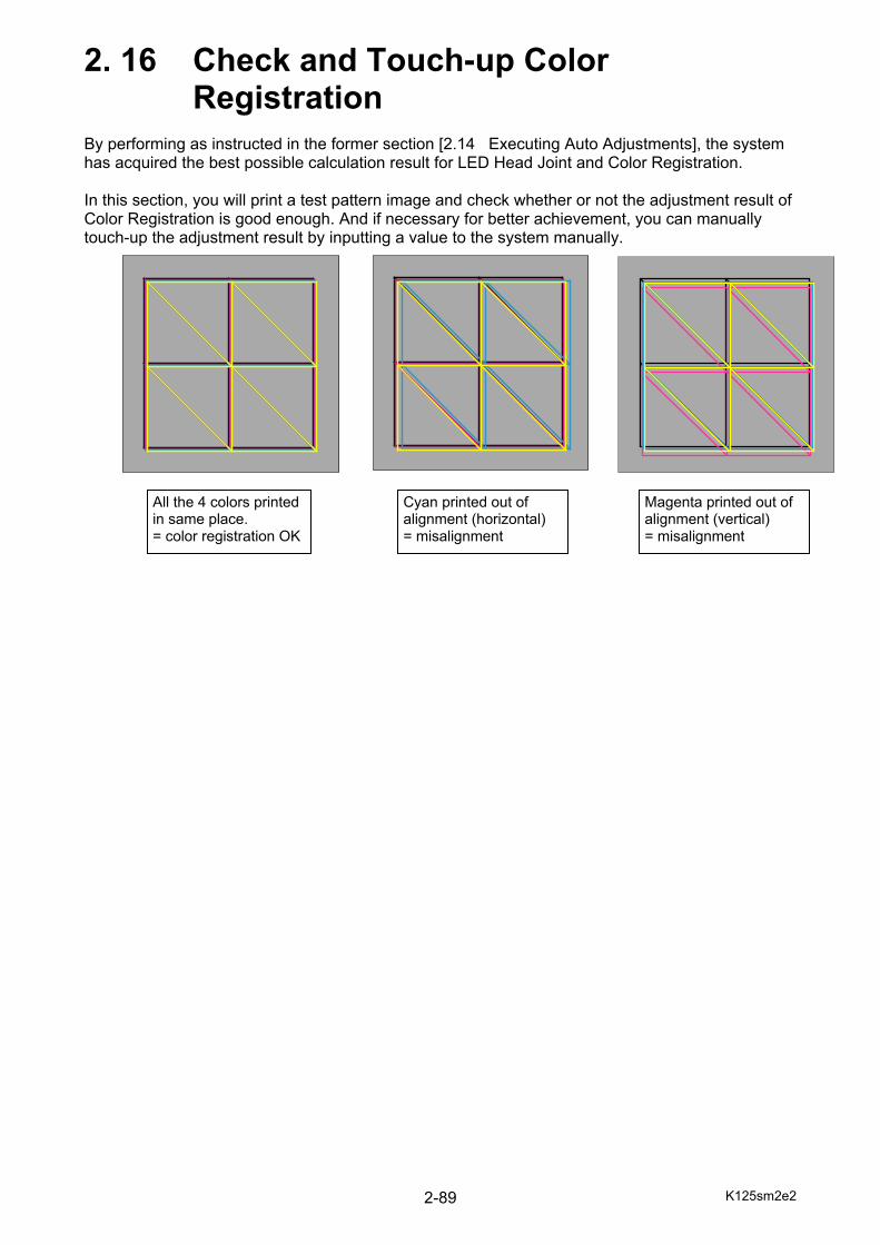
2. 16 Check and Touch-up Color Registration By performing as instructed in the former section [2.14 Executing Auto Adjustments], the system has acquired the best possible calculation result for LED Head Joint and Color Registration. In this section, you will print a test pattern image and check whether or not the adjustment result of Color Registration is good enough. And if necessary for better achievement, you can manually touch-up the adjustment result by inputting a value to the system manually.
All the 4 colors printed in same place. = color registration OK
Cyan printed out of alignment (horizontal) = misalignment
Magenta printed out of alignment (vertical) = misalignment
K125sm2e2 2-90
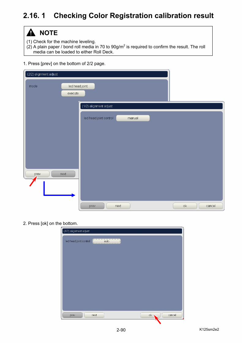
2.16. 1 Checking Color Registration calibration result 1. Press [prev] on the bottom of 2/2 page. 2. Press [ok] on the bottom.
NOTE (1) Check for the machine leveling. (2) A plain paper / bond roll media in 70 to 90g/m2 is required to confirm the result. The roll
media can be loaded to either Roll Deck.

K125sm2e2 2-91
3. Press [test print] on the Home screen. 4. Press [browse] to locate “No18.zip” as a test pattern image. Press [deck] button to select the
media source (deck number). Configure the other settings as follows and then press [ok]. Press [ok] on the bottom to run test printing.
Select the deck number of the media being loaded
K125sm2e2 2-92
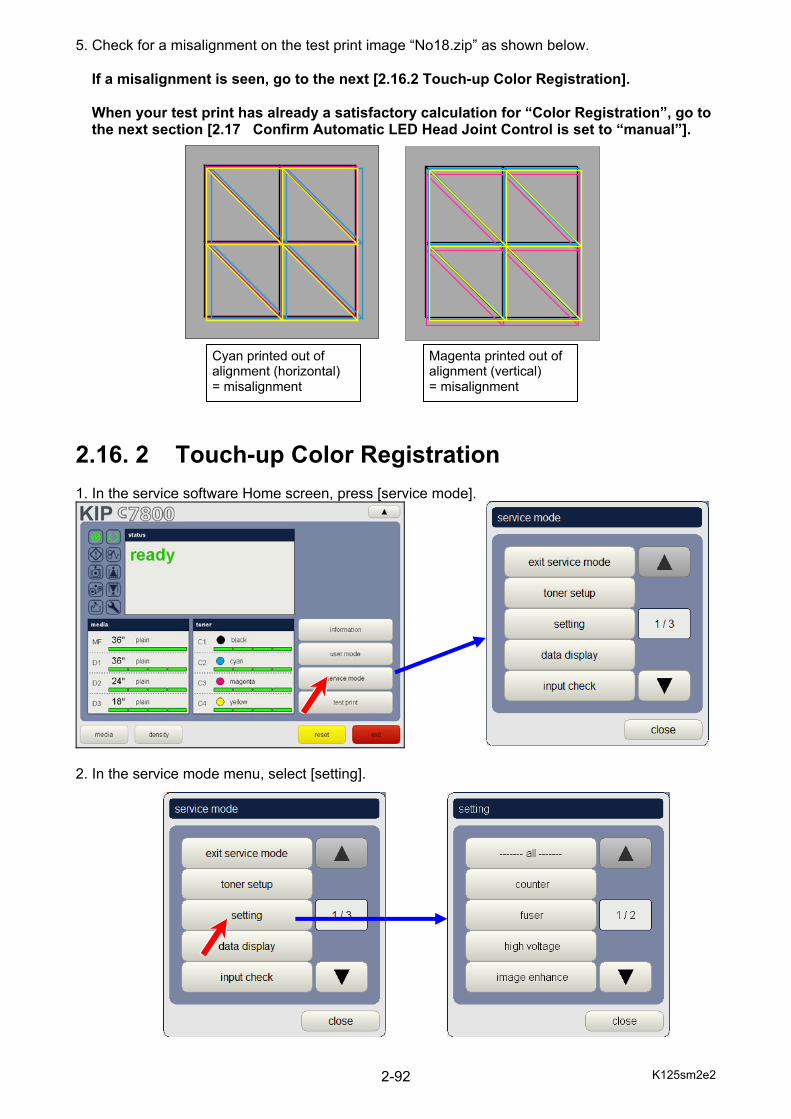
5. Check for a misalignment on the test print image “No18.zip” as shown below. If a misalignment is seen, go to the next [2.16.2 Touch-up Color Registration]. When your test print has already a satisfactory calculation for “Color Registration”, go to the next section [2.17 Confirm Automatic LED Head Joint Control is set to “manual”].
2.16. 2 Touch-up Color Registration 1. In the service software Home screen, press [service mode].
2. In the service mode menu, select [setting].
Cyan printed out of alignment (horizontal) = misalignment
Magenta printed out of alignment (vertical) = misalignment

K125sm2e2 2-93
3. In the category menu, press button to scroll the page to 2/2, and then select [image/print position].
K125sm2e2 2-94
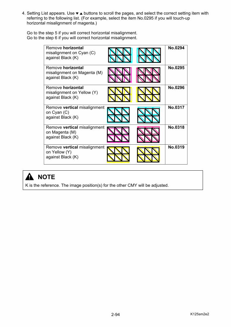
4. Setting List appears. Use buttons to scroll the pages, and select the correct setting item with referring to the following list. (For example, select the item No.0295 if you will touch-up horizontal misalignment of magenta.)
Go to the step 5 if you will correct horizontal misalignment. Go to the step 6 if you will correct horizontal misalignment.
Remove horizontal misalignment on Cyan (C) against Black (K)
No.0294
Remove horizontal misalignment on Magenta (M) against Black (K)
No.0295
Remove horizontal misalignment on Yellow (Y) against Black (K)
No.0296
Remove vertical misalignment on Cyan (C) against Black (K)
No.0317
Remove vertical misalignment on Magenta (M) against Black (K)
No.0318
Remove vertical misalignment on Yellow (Y) against Black (K)
No.0319
NOTE K is the reference. The image position(s) for the other CMY will be adjusted.
K125sm2e2 2-95
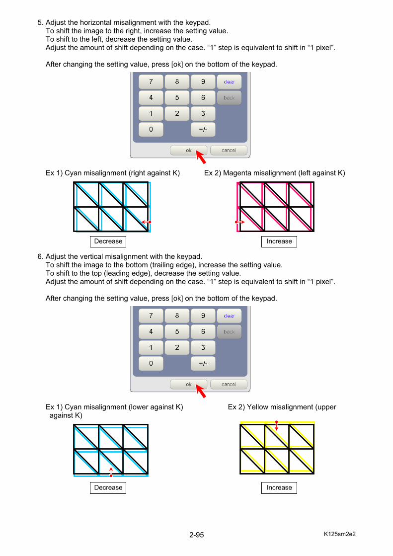
5. Adjust the horizontal misalignment with the keypad. To shift the image to the right, increase the setting value. To shift to the left, decrease the setting value. Adjust the amount of shift depending on the case. “1” step is equivalent to shift in “1 pixel”. After changing the setting value, press [ok] on the bottom of the keypad. Ex 1) Cyan misalignment (right against K) Ex 2) Magenta misalignment (left against K) 6. Adjust the vertical misalignment with the keypad. To shift the image to the bottom (trailing edge), increase the setting value. To shift to the top (leading edge), decrease the setting value. Adjust the amount of shift depending on the case. “1” step is equivalent to shift in “1 pixel”. After changing the setting value, press [ok] on the bottom of the keypad. Ex 1) Cyan misalignment (lower against K) Ex 2) Yellow misalignment (upper
against K)
Decrease Increase
Decrease Increase
K125sm2e2 2-96
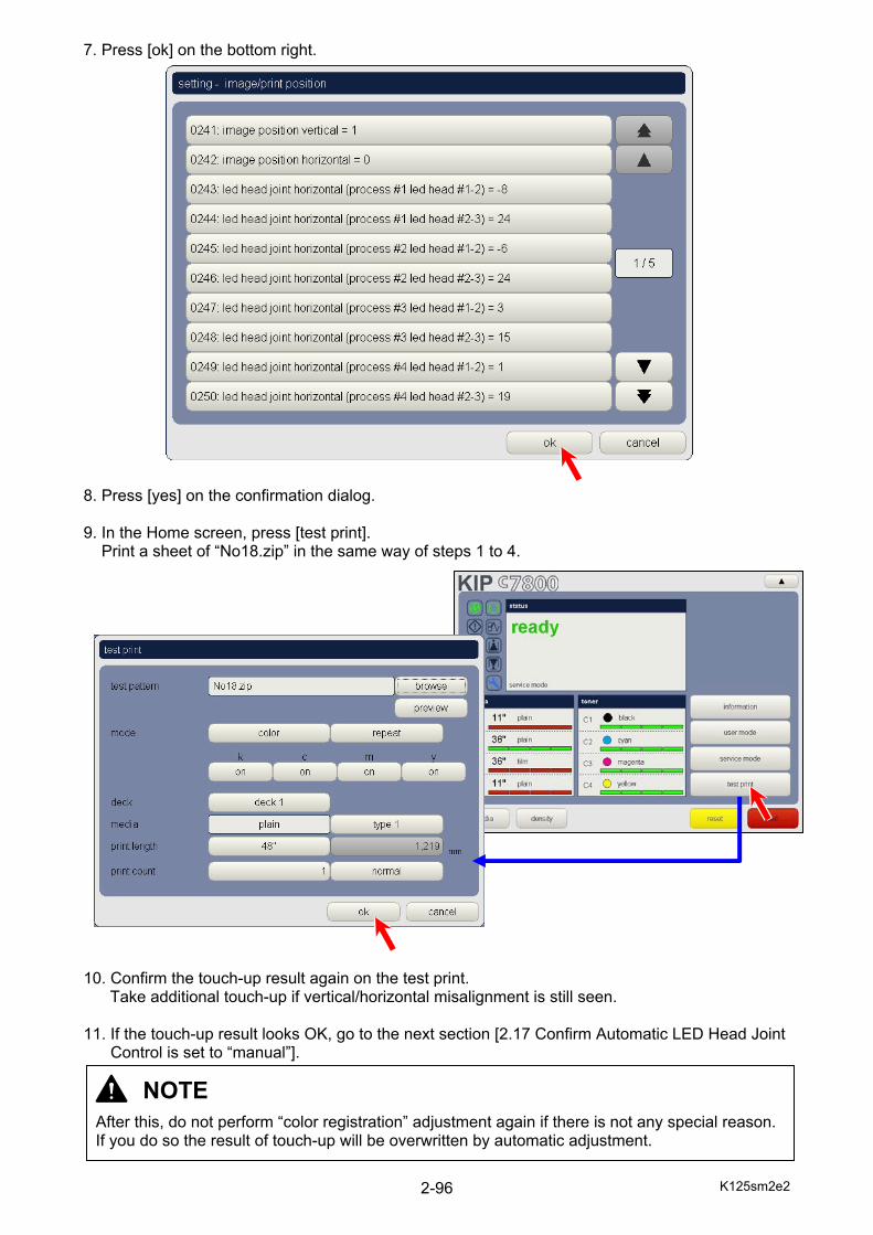
7. Press [ok] on the bottom right. 8. Press [yes] on the confirmation dialog. 9. In the Home screen, press [test print]. Print a sheet of “No18.zip” in the same way of steps 1 to 4. 10. Confirm the touch-up result again on the test print.
Take additional touch-up if vertical/horizontal misalignment is still seen. 11. If the touch-up result looks OK, go to the next section [2.17 Confirm Automatic LED Head Joint Control is set to “manual”].
NOTE After this, do not perform “color registration” adjustment again if there is not any special reason. If you do so the result of touch-up will be overwritten by automatic adjustment.

K125sm2e2 2-97
2. 17 Confirm Automatic LED Head Joint Control is set to “manual” When LED Joint Control adjustment has been correctly achieved, please set Automatic LED Head Joint Control to “manual” so that it should not automatically change and overwrite the current setting. 1. Press [user mode] on the right of the home screen. 2. Select [alignment adjust].
NOTE If Automatic LED Head Joint is set to “auto”, it will automatically take readjustment every day and change the values.
K125sm2e2 2-98
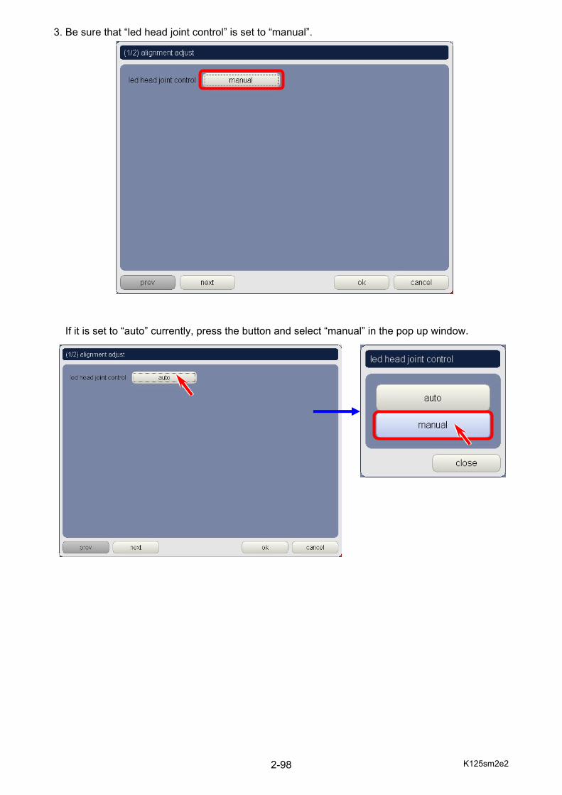
3. Be sure that “led head joint control” is set to “manual”. If it is set to “auto” currently, press the button and select “manual” in the pop up window.
K125sm2e2 2-99
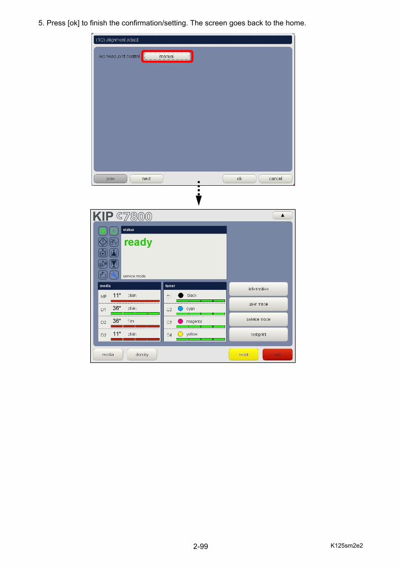
5. Press [ok] to finish the confirmation/setting. The screen goes back to the home.
K125sm2e2 2-100
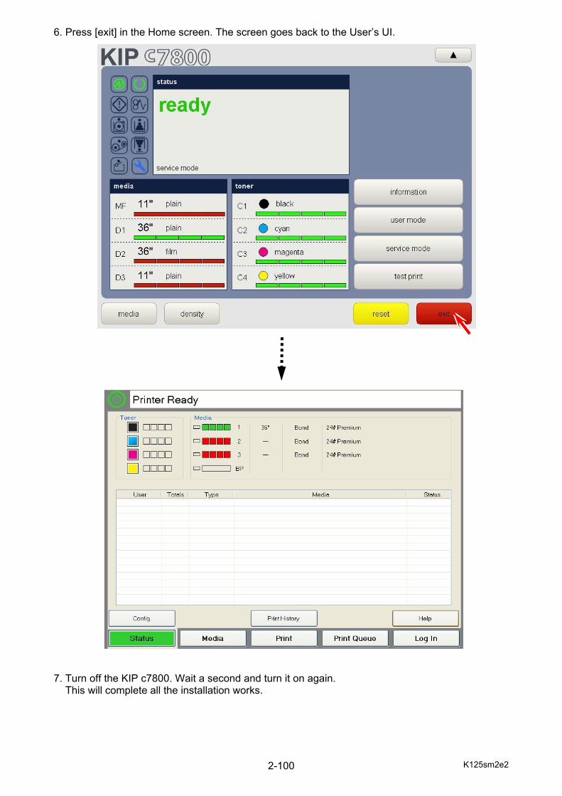
6. Press [exit] in the Home screen. The screen goes back to the User’s UI. 7. Turn off the KIP c7800. Wait a second and turn it on again. This will complete all the installation works.

K125sm2e2 2-101
POWER CORD INSTRUCTION The installation of (or exchange to) a power plug which fits in the wall outlet of the installation location shall be conducted in accordance with the following:
WARNING Select a power plug which meets the following criteria;
- The plug has a voltage and current rating appropriate for the product’s rating marked on its name plate.
- The plug meets regulatory requirements for the area. - The plug is provided with a grounding pin or terminal.
If the appropriate plug does not fit the wall outlet in the installation, the customer shall install an appropriate outlet. Connector Type:
Configuration Standard Rating Usually found in
IEC60320:C19 20A 250V (UL) 16A 250V (IEC)
Plug Type: Model Rating 220-240V
Configuration Standard Rating Usually found in
NEMA6-20 20A 250V North America (UL Listed)
CEE7/7 16A 250V European countries
KS C 8305 16A 250V Korea
AS/NZS 3112 16A 250V Australia New Zealand
GB1002 GB2099.1
16A 250V China
IRAM 2073 16A 250V Argentina
Cord Type
Standard Rating Usually found in SJT 3X12AWG Long <4.5m 20A 250V North America
(UL Listed)
HO5VV-F 3X1.5mm2 16A 250V European countries Argentina
RVV 3X1.5mm2 16A 250V China
K125sm3e1 3-1
Chapter 3
Print Process & Control
Page 3. 1 General Outline of the Print Process 3- 2 3. 1. 1 Characteristic of toner 3- 2 3. 1. 2 Overall flow of print process 3- 3 3. 2 Description of Each Step of Print Process 3- 5 3. 2. 1 Cutting the media 3- 5 3. 2. 2 Tightening the media (long print only) 3- 7 3. 2. 3 Media Charging 3- 8 3. 2. 4 Erasing 3- 9 3. 2. 5 Drum charging 3-10 3. 2. 6 Exposure 3-11 3. 2. 7 Development 3-13 3. 2. 8 Transfer of toner image onto media 3-15 3. 2. 9 Separation of media 3-17 3. 2.10 Fusing 3-19 3. 2.11 Drum cleaning 3-20 3. 2.12 Belt cleaning 3-21 3. 3 Controlling the movement of toner in the Developer Unit 3-22 3. 4 Automatic Controls 3-25 3. 4. 1 Density Control 3-25 3. 4. 1. 1 Density Lock 3-26 3. 4. 1. 2 Density Control 3-28 3. 4. 2 Automatic Transfer Roller Voltage Adjustment 3-30
K125sm3e1 3-2
3. 1 General Outline of the Print Process
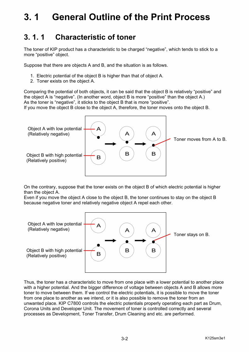
3. 1. 1 Characteristic of toner The toner of KIP product has a characteristic to be charged “negative”, which tends to stick to a more “positive” object. Suppose that there are objects A and B, and the situation is as follows. 1. Electric potential of the object B is higher than that of object A. 2. Toner exists on the object A. Comparing the potential of both objects, it can be said that the object B is relatively “positive” and the object A is “negative”. (In another word, object B is more “positive” than the object A.) As the toner is “negative”, it sticks to the object B that is more “positive”. If you move the object B close to the object A, therefore, the toner moves onto the object B. Object A with low potential (Relatively negative) Toner moves from A to B. Object B with high potential (Relatively positive) On the contrary, suppose that the toner exists on the object B of which electric potential is higher than the object A. Even if you move the object A close to the object B, the toner continues to stay on the object B because negative toner and relatively negative object A repel each other. Object A with low potential (Relatively negative) Toner stays on B. Object B with high potential (Relatively positive) Thus, the toner has a characteristic to move from one place with a lower potential to another place with a higher potential. And the bigger difference of voltage between objects A and B allows more toner to move between them. If we control the electric potentials, it is possible to move the toner from one place to another as we intend, or it is also possible to remove the toner from an unwanted place. KIP C7800 controls the electric potentials properly operating each part as Drum, Corona Units and Developer Unit. The movement of toner is controlled correctly and several processes as Development, Toner Transfer, Drum Cleaning and etc. are performed.
A
B
A
B
A
B
A
B
A
B
A
B

K125sm3e1 3-3
3. 1. 2 Overall flow of print process Print process consists of the following 12 steps.
(1) Cutting the media (2) Tightening the media (long print only) (3) Media Charging (4) Erasing (5) Drum charging (6) Exposure (7) Development (8) Transference of toner image onto media (9) Separation of media
(10) Fusing & media tension adjustment (11) Drum cleaning (12) Belt cleaning
See next page for the locations where the above steps take place in the machine.

K125sm3e1 3-4
9
1
1
1
1
2
3
8
8
8
8
4 5
6
7
11
10
12
4 5
6
7
9
11
4 5
6
7
11
4 5
6
7
11
K125sm3e1 3-5
3. 2 Description of Each Step of Print Process
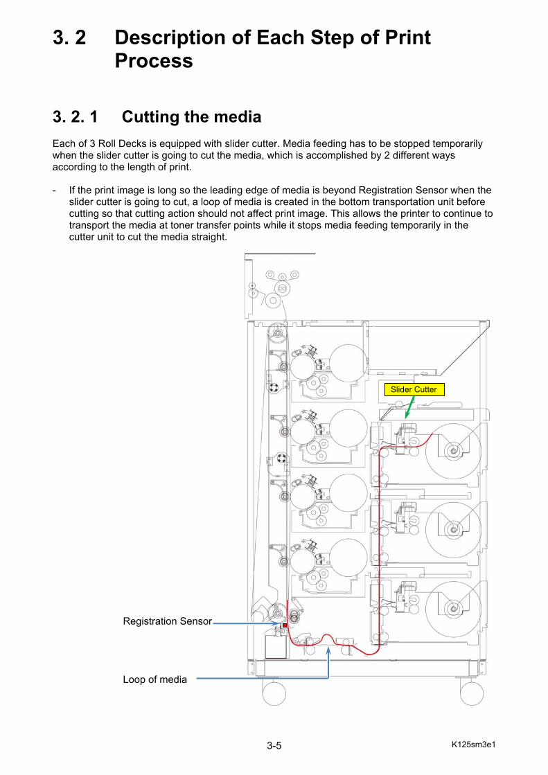
3. 2. 1 Cutting the media Each of 3 Roll Decks is equipped with slider cutter. Media feeding has to be stopped temporarily when the slider cutter is going to cut the media, which is accomplished by 2 different ways according to the length of print. - If the print image is long so the leading edge of media is beyond Registration Sensor when the
slider cutter is going to cut, a loop of media is created in the bottom transportation unit before cutting so that cutting action should not affect print image. This allows the printer to continue to transport the media at toner transfer points while it stops media feeding temporarily in the cutter unit to cut the media straight.
Registration Sensor Loop of media
Slider Cutter
K125sm3e1 3-6
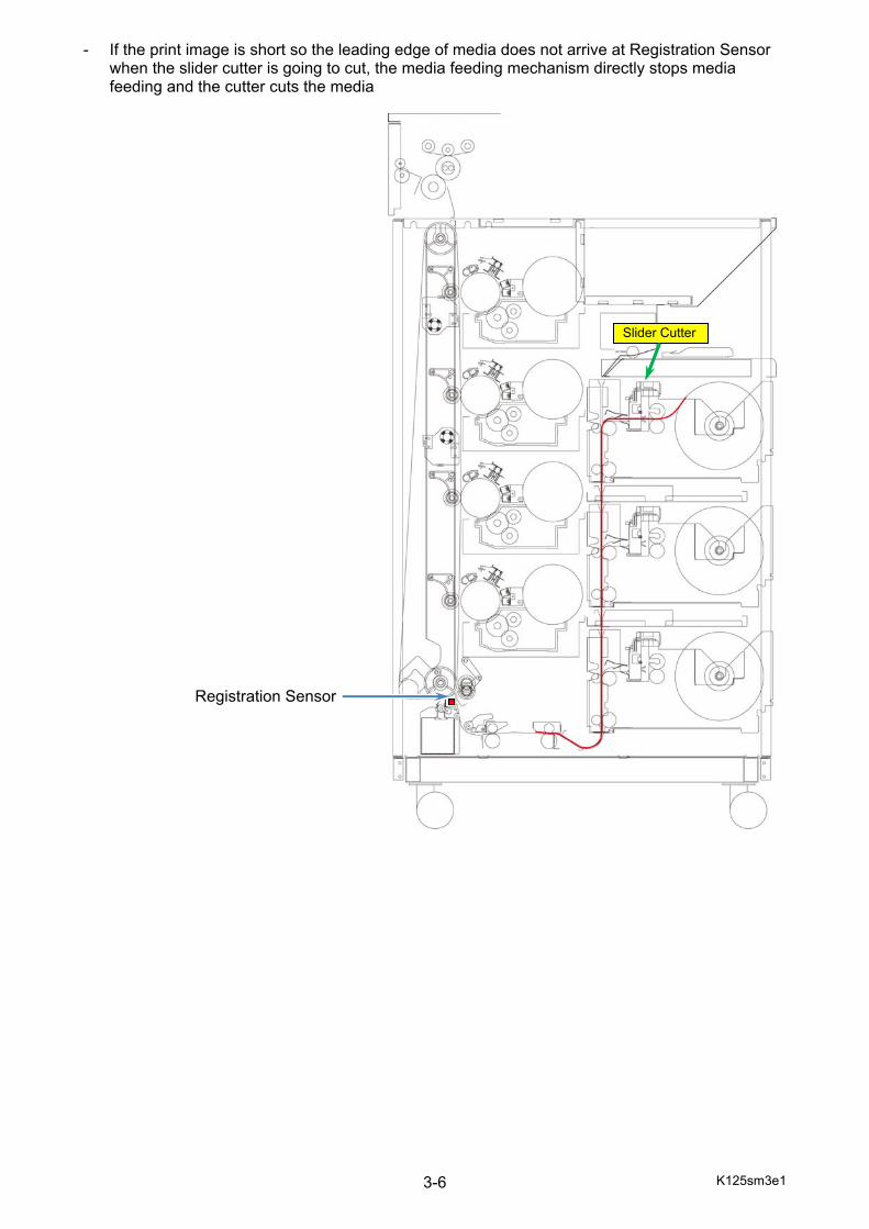
- If the print image is short so the leading edge of media does not arrive at Registration Sensor when the slider cutter is going to cut, the media feeding mechanism directly stops media feeding and the cutter cuts the media
Registration Sensor
Slider Cutter
K125sm3e1 3-7
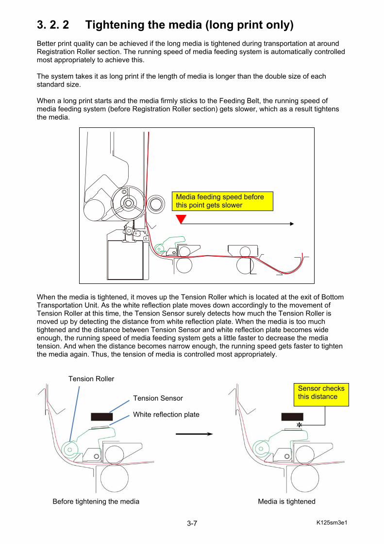
3. 2. 2 Tightening the media (long print only) Better print quality can be achieved if the long media is tightened during transportation at around Registration Roller section. The running speed of media feeding system is automatically controlled most appropriately to achieve this. The system takes it as long print if the length of media is longer than the double size of each standard size. When a long print starts and the media firmly sticks to the Feeding Belt, the running speed of media feeding system (before Registration Roller section) gets slower, which as a result tightens the media. When the media is tightened, it moves up the Tension Roller which is located at the exit of Bottom Transportation Unit. As the white reflection plate moves down accordingly to the movement of Tension Roller at this time, the Tension Sensor surely detects how much the Tension Roller is moved up by detecting the distance from white reflection plate. When the media is too much tightened and the distance between Tension Sensor and white reflection plate becomes wide enough, the running speed of media feeding system gets a little faster to decrease the media tension. And when the distance becomes narrow enough, the running speed gets faster to tighten the media again. Thus, the tension of media is controlled most appropriately. Tension Roller Before tightening the media Media is tightened
Media feeding speed before this point gets slower
Tension Sensor White reflection plate
Sensor checks this distance
K125sm3e1 3-8
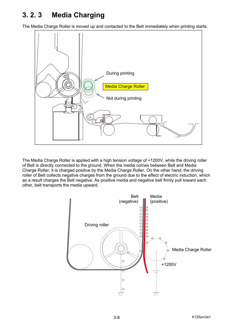
3. 2. 3 Media Charging The Media Charge Roller is moved up and contacted to the Belt immediately when printing starts. The Media Charge Roller is applied with a high tension voltage of +1200V, while the driving roller of Belt is directly connected to the ground. When the media comes between Belt and Media Charge Roller, it is charged positive by the Media Charge Roller. On the other hand, the driving roller of Belt collects negative charges from the ground due to the effect of electric induction, which as a result charges the Belt negative. As positive media and negative belt firmly pull toward each other, belt transports the media upward. Driving roller Media Charge Roller +1200V
During printing
Not during printing
Media Charge Roller
Belt (negative)
Media (positive)
K125sm3e1 3-9
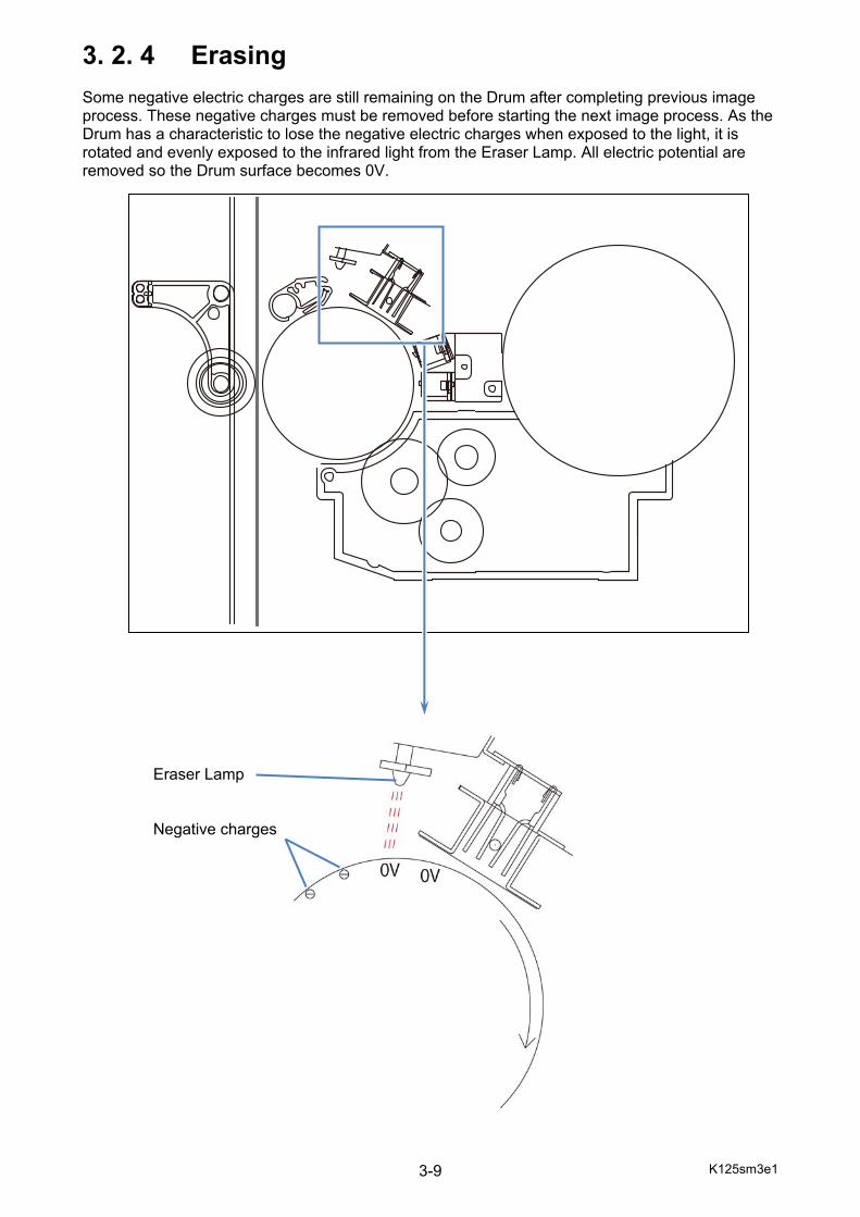
3. 2. 4 Erasing Some negative electric charges are still remaining on the Drum after completing previous image process. These negative charges must be removed before starting the next image process. As the Drum has a characteristic to lose the negative electric charges when exposed to the light, it is rotated and evenly exposed to the infrared light from the Eraser Lamp. All electric potential are removed so the Drum surface becomes 0V. Eraser Lamp Negative charges

K125sm3e1 3-10
3. 2. 5 Drum charging The Image Corona takes negative discharging, and the Drum surface is charged negatively with -XV evenly by this process. The Drum area charged with -XV corresponds to the white area of the printed image pattern.
Image Corona Wire
K125sm3e1 3-11
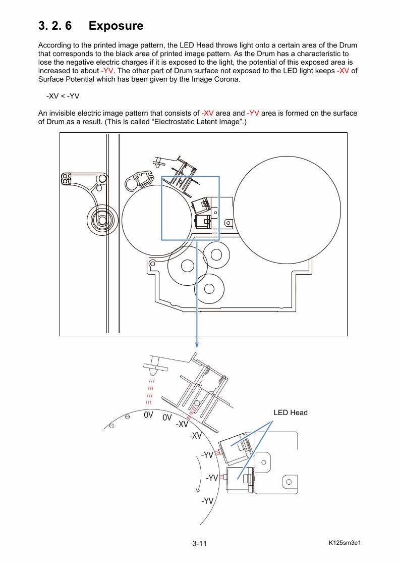
3. 2. 6 Exposure According to the printed image pattern, the LED Head throws light onto a certain area of the Drum that corresponds to the black area of printed image pattern. As the Drum has a characteristic to lose the negative electric charges if it is exposed to the light, the potential of this exposed area is increased to about -YV. The other part of Drum surface not exposed to the LED light keeps -XV of Surface Potential which has been given by the Image Corona. -XV < -YV An invisible electric image pattern that consists of -XV area and -YV area is formed on the surface of Drum as a result. (This is called “Electrostatic Latent Image”.)
LED Head
K125sm3e1 3-12
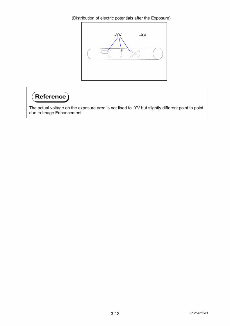
(Distribution of electric potentials after the Exposure)
-YV -XV
The actual voltage on the exposure area is not fixed to -YV but slightly different point to point due to Image Enhancement.
Reference
K125sm3e1 3-13
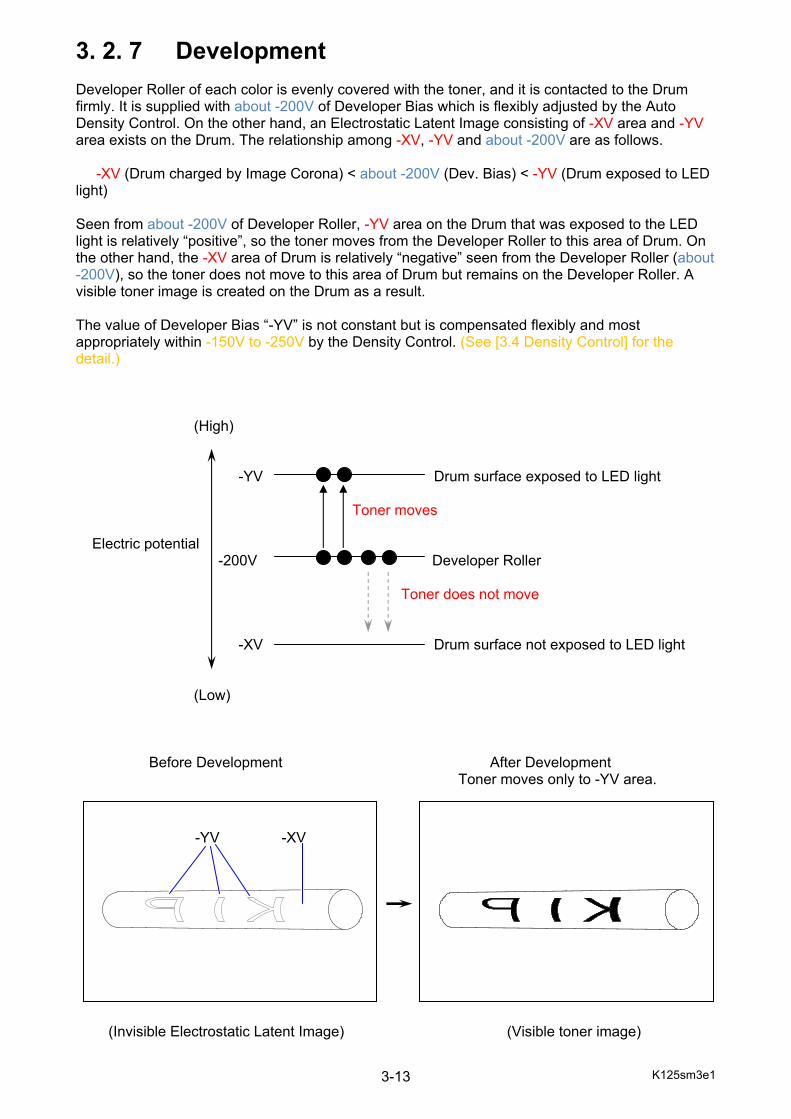
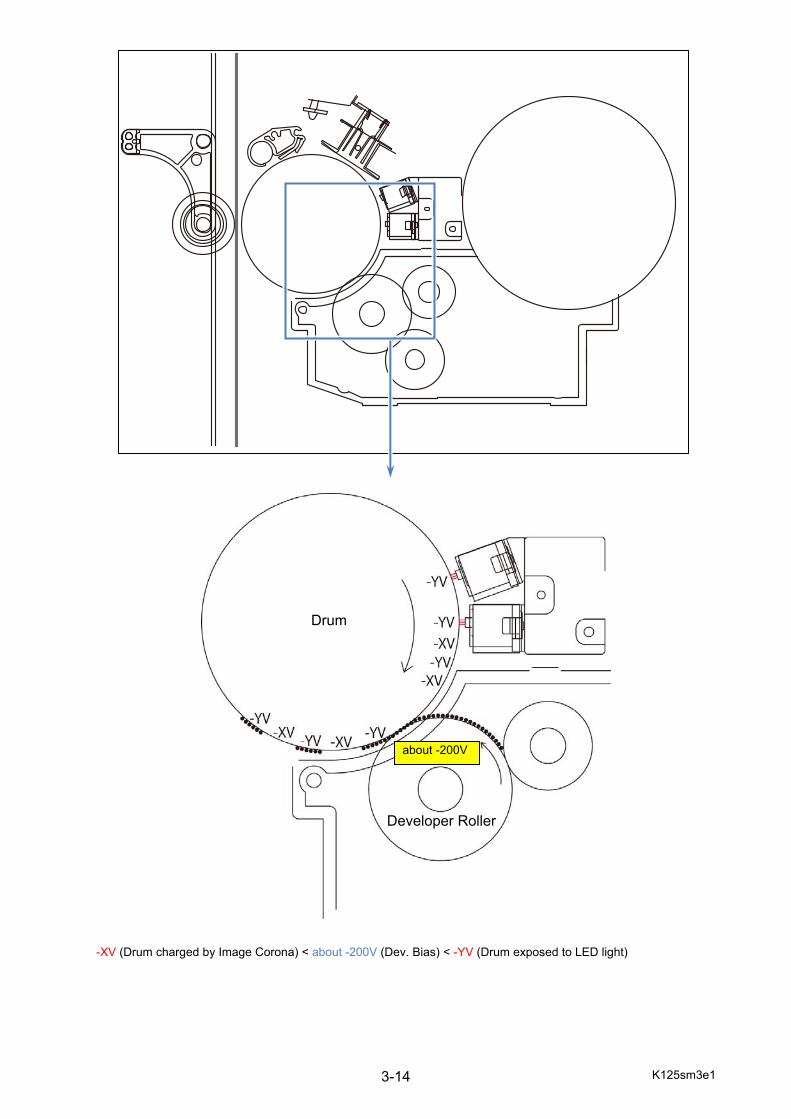
3. 2. 7 Development Developer Roller of each color is evenly covered with the toner, and it is contacted to the Drum firmly. It is supplied with about -200V of Developer Bias which is flexibly adjusted by the Auto Density Control. On the other hand, an Electrostatic Latent Image consisting of -XV area and -YV area exists on the Drum. The relationship among -XV, -YV and about -200V are as follows. -XV (Drum charged by Image Corona) < about -200V (Dev. Bias) < -YV (Drum exposed to LED light) Seen from about -200V of Developer Roller, -YV area on the Drum that was exposed to the LED light is relatively “positive”, so the toner moves from the Developer Roller to this area of Drum. On the other hand, the -XV area of Drum is relatively “negative” seen from the Developer Roller (about -200V), so the toner does not move to this area of Drum but remains on the Developer Roller. A visible toner image is created on the Drum as a result. The value of Developer Bias “-YV” is not constant but is compensated flexibly and most appropriately within -150V to -250V by the Density Control. (See [3.4 Density Control] for the detail.) (High) -YV Drum surface exposed to LED light Toner moves Electric potential -200V Developer Roller Toner does not move -XV Drum surface not exposed to LED light (Low) Before Development After Development Toner moves only to -YV area. (Invisible Electrostatic Latent Image) (Visible toner image)
-YV -XV
K125sm3e1 3-14
-XV (Drum charged by Image Corona) < about -200V (Dev. Bias) < -YV (Drum exposed to LED light)
about -200V
Drum
Developer Roller
K125sm3e1 3-15
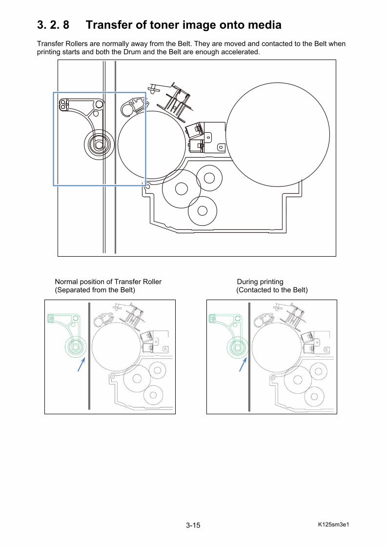
3. 2. 8 Transfer of toner image onto media Transfer Rollers are normally away from the Belt. They are moved and contacted to the Belt when printing starts and both the Drum and the Belt are enough accelerated. Normal position of Transfer Roller During printing (Separated from the Belt) (Contacted to the Belt)
K125sm3e1 3-16
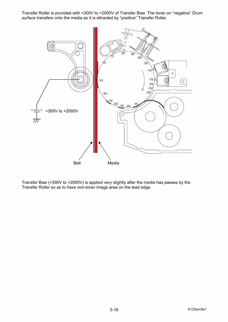
Transfer Roller is provided with +300V to +2000V of Transfer Bias. The toner on “negative” Drum surface transfers onto the media as it is attracted by “positive” Transfer Roller. Belt Media Transfer Bias (+300V to +2000V) is applied very slightly after the media has passes by the Transfer Roller so as to have non-toner image area on the lead edge.
+300V to +2000V
K125sm3e1 3-17
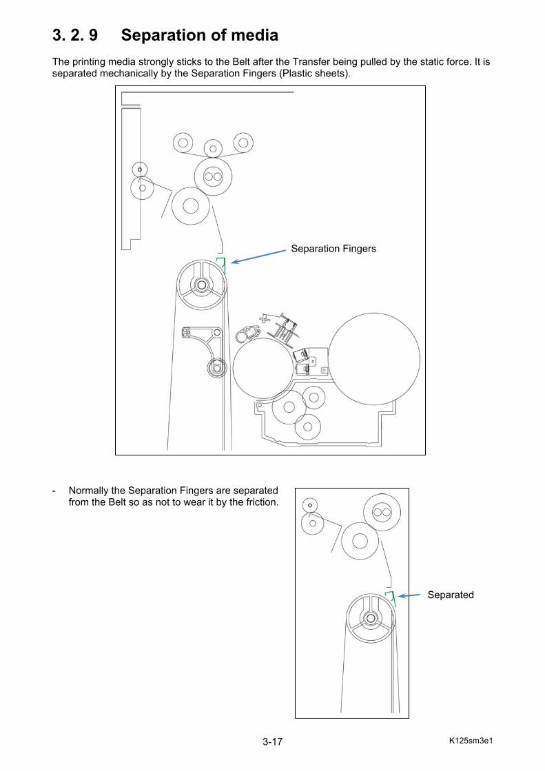
3. 2. 9 Separation of media The printing media strongly sticks to the Belt after the Transfer being pulled by the static force. It is separated mechanically by the Separation Fingers (Plastic sheets). - Normally the Separation Fingers are separated
from the Belt so as not to wear it by the friction. Separated
Separation Fingers
K125sm3e1 3-18
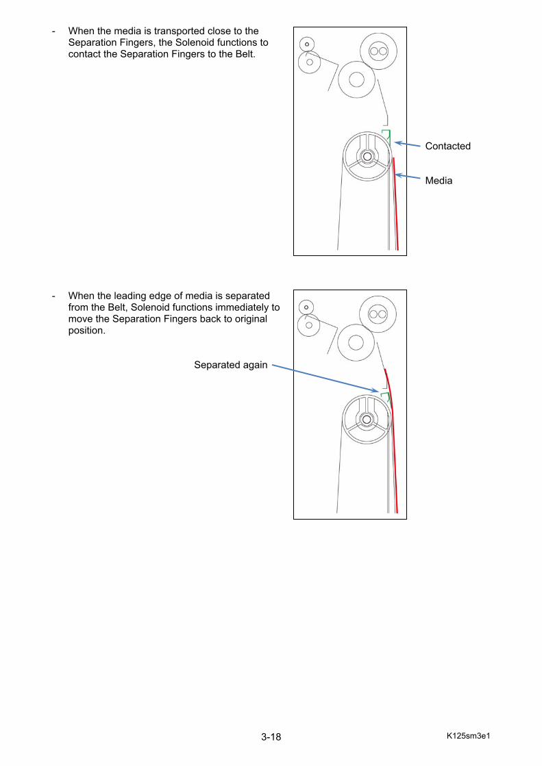
- When the media is transported close to the Separation Fingers, the Solenoid functions to contact the Separation Fingers to the Belt.
Contacted Media - When the leading edge of media is separated
from the Belt, Solenoid functions immediately to move the Separation Fingers back to original position.
Separated again
K125sm3e1 3-19
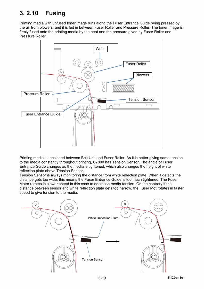
3. 2.10 Fusing Printing media with unfused toner image runs along the Fuser Entrance Guide being pressed by the air from blowers, and it is fed in between Fuser Roller and Pressure Roller. The toner image is firmly fused onto the printing media by the heat and the pressure given by Fuser Roller and Pressure Roller. Printing media is tensioned between Belt Unit and Fuser Roller. As it is better giving same tension to the media constantly throughout printing, C7800 has Tension Sensor. The angle of Fuser Entrance Guide changes as the media is tightened, which also changes the height of white reflection plate above Tension Sensor. Tension Sensor is always monitoring the distance from white reflection plate. When it detects the distance gets too wide, this means the Fuser Entrance Guide is too much tightened. The Fuser Motor rotates in slower speed in this case to decrease media tension. On the contrary if the distance between sensor and white reflection plate gets too narrow, the Fuser Mot rotates in faster speed to give tension to the media.
Tension Sensor
Blowers
Fuser Roller
Web
Pressure Roller
Fuser Entrance Guide
Tension Sensor
White Reflection Plate

K125sm3e1 3-20
3. 2.11 Drum cleaning A little toner may be remaining on the Drum after the Transfer process. And very little toner of other colors may stick to the Drum. Such toner is scraped off by the Cleaner Blade, collected into the Drum Cleaner Unit, and conveyed to the Waste Toner Box.
K125sm3e1 3-21
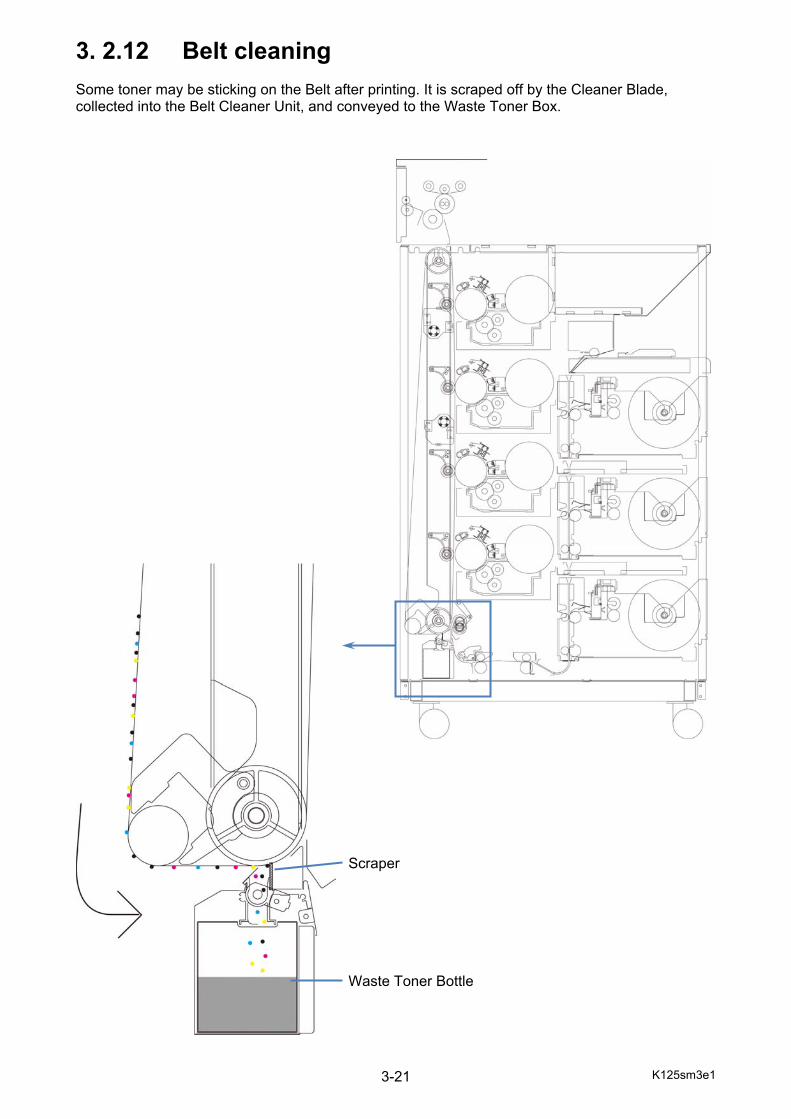
3. 2.12 Belt cleaning Some toner may be sticking on the Belt after printing. It is scraped off by the Cleaner Blade, collected into the Belt Cleaner Unit, and conveyed to the Waste Toner Box. Scraper Waste Toner Bottle
K125sm3e1 3-22
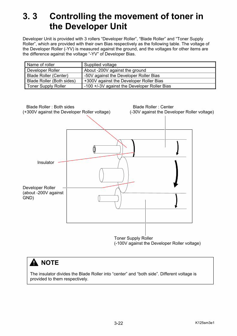
3. 3 Controlling the movement of toner in the Developer Unit Developer Unit is provided with 3 rollers “Developer Roller”, “Blade Roller” and “Toner Supply Roller”, which are provided with their own Bias respectively as the following table. The voltage of the Developer Roller (-YV) is measured against the ground, and the voltages for other items are the difference against the voltage “-YV” of Developer Bias.
Name of roller Supplied voltage Developer Roller About -200V against the ground Blade Roller (Center) -50V against the Developer Roller Bias Blade Roller (Both sides) +300V against the Developer Roller Bias Toner Supply Roller -100 +/-3V against the Developer Roller Bias
Blade Roller : Both sides Blade Roller : Center (+300V against the Developer Roller voltage) (-30V against the Developer Roller voltage) Insulator Developer Roller (about -200V against GND) Toner Supply Roller (-100V against the Developer Roller voltage)
NOTE The insulator divides the Blade Roller into “center” and “both side”. Different voltage is provided to them respectively.
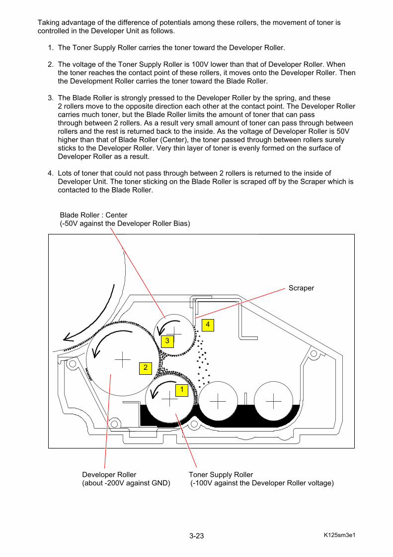
K125sm3e1 3-23
Taking advantage of the difference of potentials among these rollers, the movement of toner is controlled in the Developer Unit as follows. 1. The Toner Supply Roller carries the toner toward the Developer Roller. 2. The voltage of the Toner Supply Roller is 100V lower than that of Developer Roller. When the toner reaches the contact point of these rollers, it moves onto the Developer Roller. Then the Development Roller carries the toner toward the Blade Roller. 3. The Blade Roller is strongly pressed to the Developer Roller by the spring, and these 2 rollers move to the opposite direction each other at the contact point. The Developer Roller carries much toner, but the Blade Roller limits the amount of toner that can pass through between 2 rollers. As a result very small amount of toner can pass through between rollers and the rest is returned back to the inside. As the voltage of Developer Roller is 50V higher than that of Blade Roller (Center), the toner passed through between rollers surely sticks to the Developer Roller. Very thin layer of toner is evenly formed on the surface of Developer Roller as a result. 4. Lots of toner that could not pass through between 2 rollers is returned to the inside of Developer Unit. The toner sticking on the Blade Roller is scraped off by the Scraper which is contacted to the Blade Roller. Blade Roller : Center (-50V against the Developer Roller Bias) Developer Roller Toner Supply Roller (about -200V against GND) (-100V against the Developer Roller voltage)
Scraper
1
2
3
4
K125sm3e1 3-24
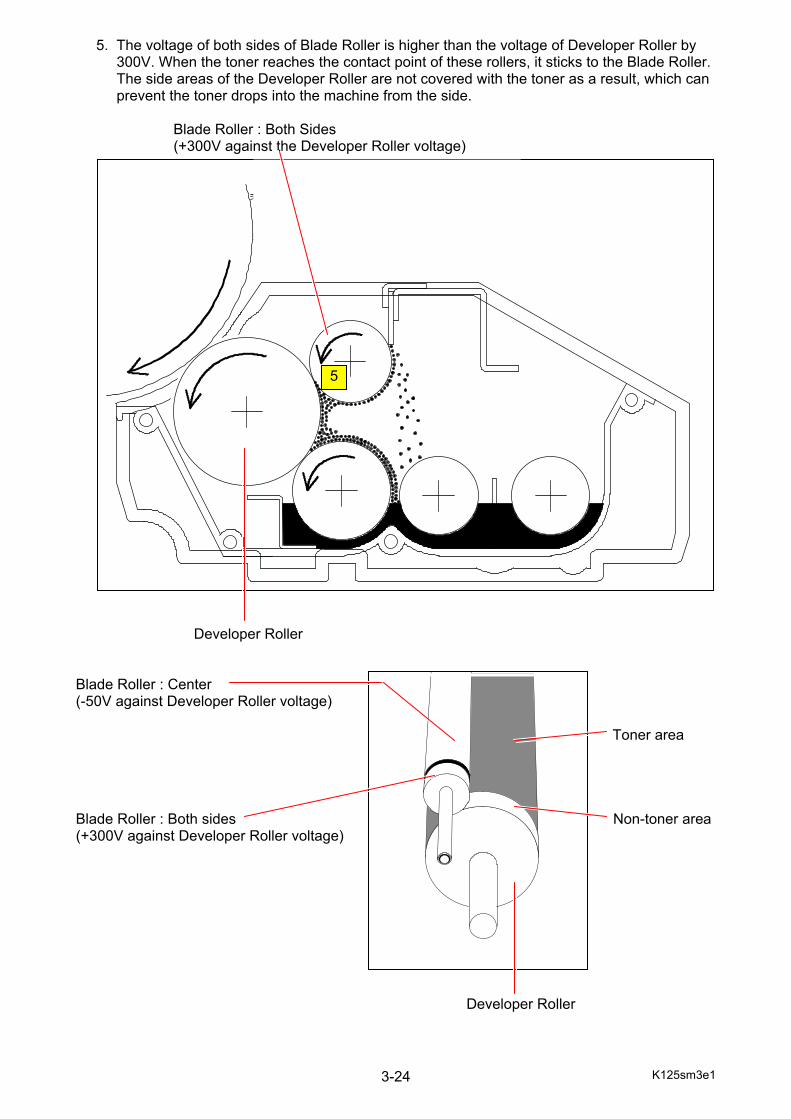
5. The voltage of both sides of Blade Roller is higher than the voltage of Developer Roller by 300V. When the toner reaches the contact point of these rollers, it sticks to the Blade Roller. The side areas of the Developer Roller are not covered with the toner as a result, which can prevent the toner drops into the machine from the side. Blade Roller : Both Sides (+300V against the Developer Roller voltage) Developer Roller Blade Roller : Center (-50V against Developer Roller voltage) Toner area Blade Roller : Both sides Non-toner area (+300V against Developer Roller voltage) Developer Roller
5
K125sm3e2 3-25
3. 4 Automatic Controls
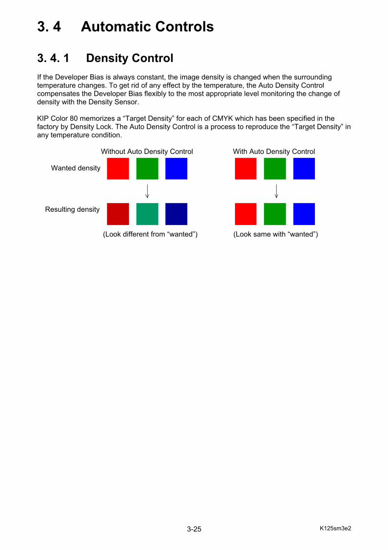
3. 4. 1 Density Control If the Developer Bias is always constant, the image density is changed when the surrounding temperature changes. To get rid of any effect by the temperature, the Auto Density Control compensates the Developer Bias flexibly to the most appropriate level monitoring the change of density with the Density Sensor. KIP Color 80 memorizes a “Target Density” for each of CMYK which has been specified in the factory by Density Lock. The Auto Density Control is a process to reproduce the “Target Density” in any temperature condition. Without Auto Density Control With Auto Density Control Wanted density Resulting density (Look different from “wanted”) (Look same with “wanted”)
K125sm3e2 3-26
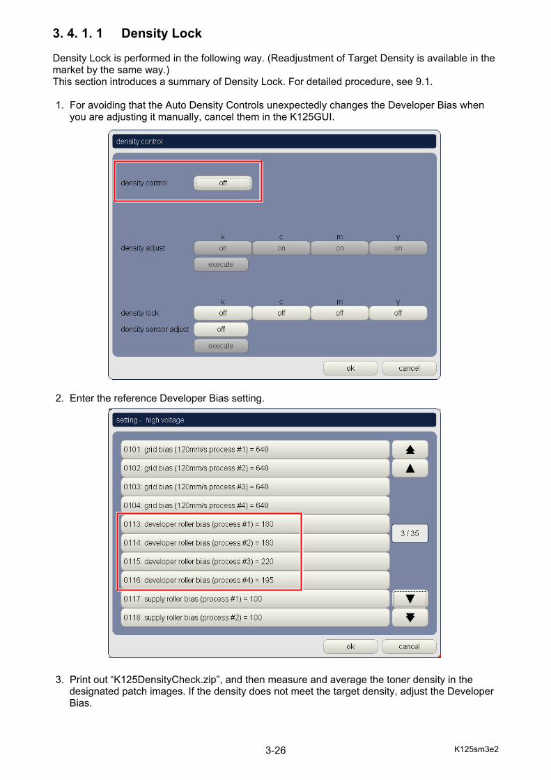
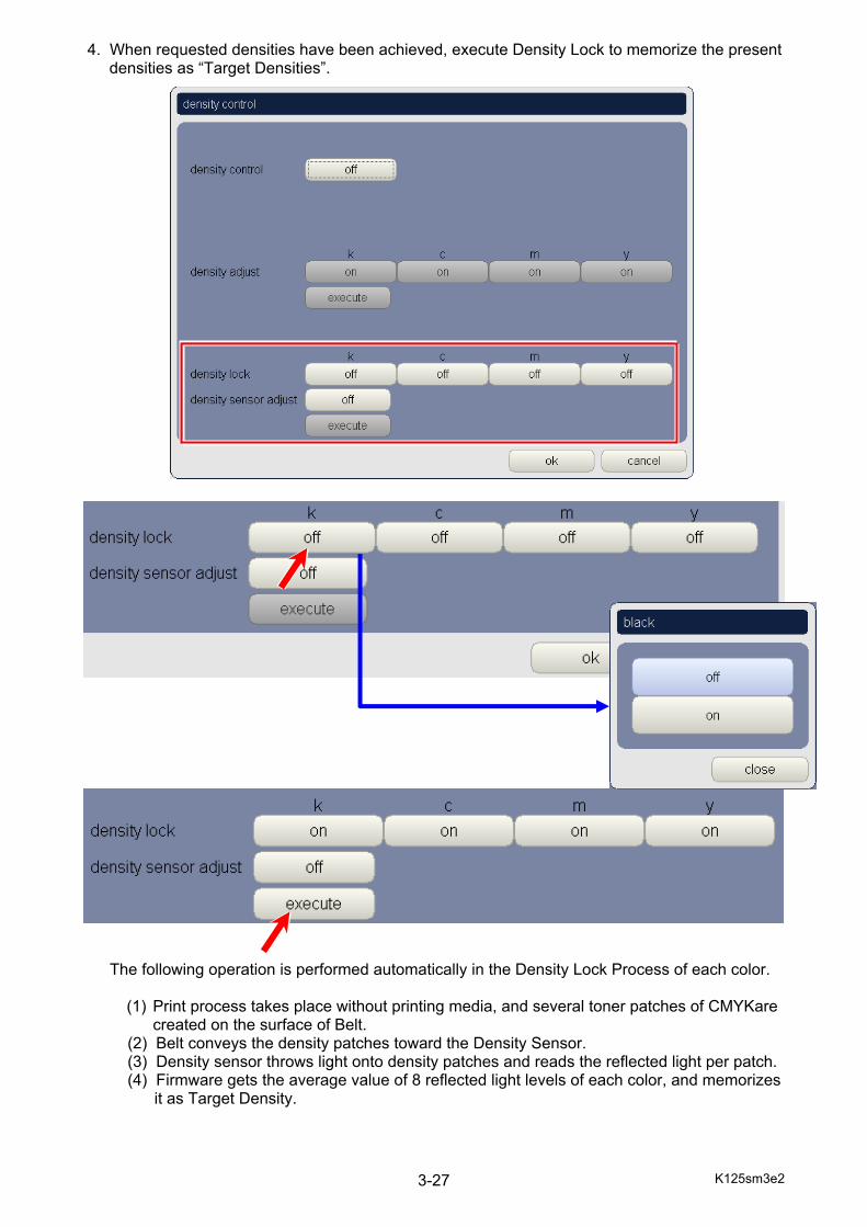
3. 4. 1. 1 Density Lock Density Lock is performed in the following way. (Readjustment of Target Density is available in the market by the same way.) This section introduces a summary of Density Lock. For detailed procedure, see 9.1. 1. For avoiding that the Auto Density Controls unexpectedly changes the Developer Bias when you are adjusting it manually, cancel them in the K125GUI. 2. Enter the reference Developer Bias setting. 3. Print out “K125DensityCheck.zip”, and then measure and average the toner density in the
designated patch images. If the density does not meet the target density, adjust the Developer Bias.
K125sm3e2 3-27
4. When requested densities have been achieved, execute Density Lock to memorize the present densities as “Target Densities”.
The following operation is performed automatically in the Density Lock Process of each color.
(1) Print process takes place without printing media, and several toner patches of CMYKare created on the surface of Belt.
(2) Belt conveys the density patches toward the Density Sensor. (3) Density sensor throws light onto density patches and reads the reflected light per patch. (4) Firmware gets the average value of 8 reflected light levels of each color, and memorizes it as Target Density.
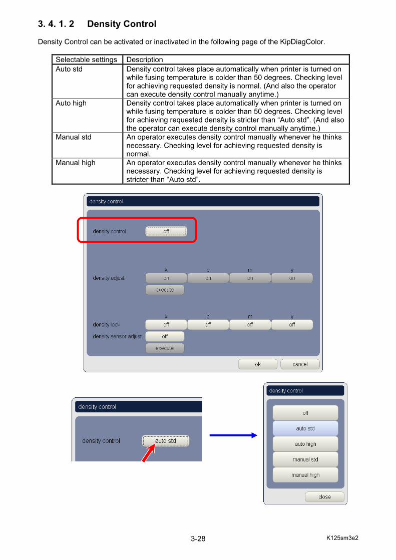
K125sm3e2 3-28
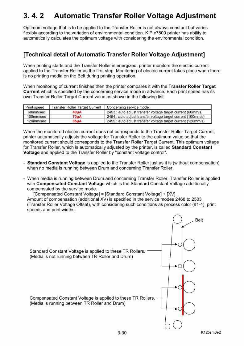
3. 4. 1. 2 Density Control Density Control can be activated or inactivated in the following page of the KipDiagColor.
Selectable settings Description Auto std Density control takes place automatically when printer is turned on
while fusing temperature is colder than 50 degrees. Checking level for achieving requested density is normal. (And also the operator can execute density control manually anytime.)
Auto high Density control takes place automatically when printer is turned on while fusing temperature is colder than 50 degrees. Checking level for achieving requested density is stricter than “Auto std”. (And also the operator can execute density control manually anytime.)
Manual std An operator executes density control manually whenever he thinks necessary. Checking level for achieving requested density is normal.
Manual high An operator executes density control manually whenever he thinks necessary. Checking level for achieving requested density is stricter than “Auto std”.

K125sm3e2 3-29
Density Control adjusts the density as follows.
(1) Print process takes place without printing media, and 8 each CMYK of density patch is created on the surface of Belt.
(2) Belt conveys the density patches toward the Density Sensor. (3) Density sensor throws light onto density patches and reads the reflected light per patch. (4) Firmware gets the average value of 8 reflected light levels (= density) of each color. (5) Firmware compares the average density of each CMYK with Target Density. If the average is within tolerance of Target Density it means correct density has been achieved, so Density Control finishes adjustment. If not within tolerance, Density Controls tries the same thing (1 to 5) again. (6) If correct density is still not achieved after 5 times trials, Density Control error is shown.
K125sm3e2 3-30
3. 4. 2 Automatic Transfer Roller Voltage Adjustment Optimum voltage that is to be applied to the Transfer Roller is not always constant but varies flexibly according to the variation of environmental condition. KIP c7800 printer has ability to automatically calculates the optimum voltage with considering the environmental condition. [Technical detail of Automatic Transfer Roller Voltage Adjustment] When printing starts and the Transfer Roller is energized, printer monitors the electric current applied to the Transfer Roller as the first step. Monitoring of electric current takes place when there is no printing media on the Belt during printing operation. When monitoring of current finishes then the printer compares it with the Transfer Roller Target Current which is specified by the concerning service mode in advance. Each print speed has its own Transfer Roller Target Current value as shown in the following list.
Print speed Transfer Roller Target Current Concerning service mode 60mm/sec 40μA 2453 : auto adjust transfer voltage target current (60mm/s) 100mm/sec 70μA 2454 : auto adjust transfer voltage target current (100mm/s) 120mm/sec 85μA 2455 : auto adjust transfer voltage target current (120mm/s)
When the monitored electric current does not corresponds to the Transfer Roller Target Current, printer automatically adjusts the voltage for Transfer Roller to the optimum value so that the monitored current should corresponds to the Transfer Roller Target Current. This optimum voltage for Transfer Roller, which is automatically adjusted by the printer, is called Standard Constant Voltage and applied to the Transfer Roller by "constant voltage control". - Standard Constant Voltage is applied to the Transfer Roller just as it is (without compensation) when no media is running between Drum and concerning Transfer Roller. - When media is running between Drum and concerning Transfer Roller, Transfer Roller is applied with Compensated Constant Voltage which is the Standard Constant Voltage additionally compensated by the service mode. [Compensated Constant Voltage] = [Standard Constant Voltage] + [XV] Amount of compensation (additional XV) is specified in the service modes 2468 to 2503 (Transfer Roller Voltage Offset), with considering such conditions as process color (#1-4), print speeds and print widths. Belt Standard Constant Voltage is applied to these TR Rollers. (Media is not running between TR Roller and Drum) Compensated Constant Voltage is applied to these TR Rollers. (Media is running between TR Roller and Drum)
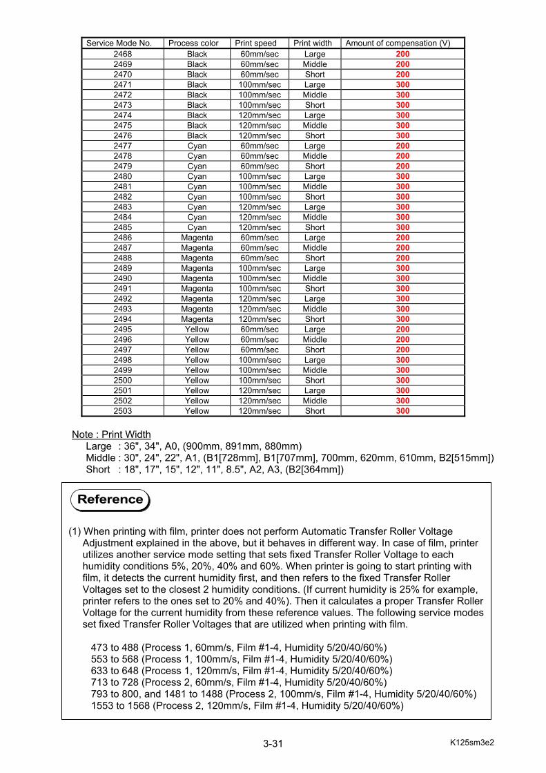
K125sm3e2 3-31
Service Mode No. Process color Print speed Print width Amount of compensation (V)
2468 Black 60mm/sec Large 200 2469 Black 60mm/sec Middle 200 2470 Black 60mm/sec Short 200 2471 Black 100mm/sec Large 300 2472 Black 100mm/sec Middle 300 2473 Black 100mm/sec Short 300 2474 Black 120mm/sec Large 300 2475 Black 120mm/sec Middle 300 2476 Black 120mm/sec Short 300 2477 Cyan 60mm/sec Large 200 2478 Cyan 60mm/sec Middle 200 2479 Cyan 60mm/sec Short 200 2480 Cyan 100mm/sec Large 300 2481 Cyan 100mm/sec Middle 300 2482 Cyan 100mm/sec Short 300 2483 Cyan 120mm/sec Large 300 2484 Cyan 120mm/sec Middle 300 2485 Cyan 120mm/sec Short 300 2486 Magenta 60mm/sec Large 200 2487 Magenta 60mm/sec Middle 200 2488 Magenta 60mm/sec Short 200 2489 Magenta 100mm/sec Large 300 2490 Magenta 100mm/sec Middle 300 2491 Magenta 100mm/sec Short 300 2492 Magenta 120mm/sec Large 300 2493 Magenta 120mm/sec Middle 300 2494 Magenta 120mm/sec Short 300 2495 Yellow 60mm/sec Large 200 2496 Yellow 60mm/sec Middle 200 2497 Yellow 60mm/sec Short 200 2498 Yellow 100mm/sec Large 300 2499 Yellow 100mm/sec Middle 300 2500 Yellow 100mm/sec Short 300 2501 Yellow 120mm/sec Large 300 2502 Yellow 120mm/sec Middle 300 2503 Yellow 120mm/sec Short 300
Note : Print Width Large : 36", 34", A0, (900mm, 891mm, 880mm) Middle : 30", 24", 22", A1, (B1[728mm], B1[707mm], 700mm, 620mm, 610mm, B2[515mm]) Short : 18", 17", 15", 12", 11", 8.5", A2, A3, (B2[364mm])
Reference
(1) When printing with film, printer does not perform Automatic Transfer Roller Voltage Adjustment explained in the above, but it behaves in different way. In case of film, printer utilizes another service mode setting that sets fixed Transfer Roller Voltage to each humidity conditions 5%, 20%, 40% and 60%. When printer is going to start printing with film, it detects the current humidity first, and then refers to the fixed Transfer Roller Voltages set to the closest 2 humidity conditions. (If current humidity is 25% for example, printer refers to the ones set to 20% and 40%). Then it calculates a proper Transfer Roller Voltage for the current humidity from these reference values. The following service modes set fixed Transfer Roller Voltages that are utilized when printing with film. 473 to 488 (Process 1, 60mm/s, Film #1-4, Humidity 5/20/40/60%) 553 to 568 (Process 1, 100mm/s, Film #1-4, Humidity 5/20/40/60%) 633 to 648 (Process 1, 120mm/s, Film #1-4, Humidity 5/20/40/60%) 713 to 728 (Process 2, 60mm/s, Film #1-4, Humidity 5/20/40/60%) 793 to 800, and 1481 to 1488 (Process 2, 100mm/s, Film #1-4, Humidity 5/20/40/60%) 1553 to 1568 (Process 2, 120mm/s, Film #1-4, Humidity 5/20/40/60%)
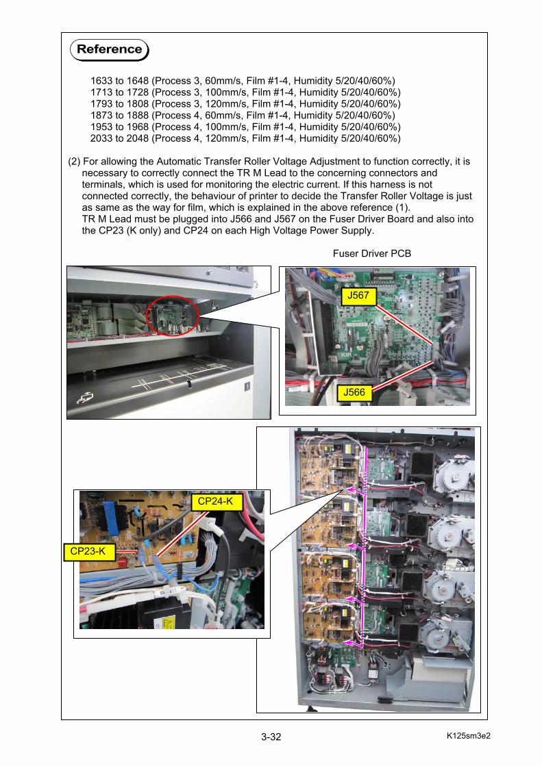
K125sm3e2 3-32
Reference
1633 to 1648 (Process 3, 60mm/s, Film #1-4, Humidity 5/20/40/60%) 1713 to 1728 (Process 3, 100mm/s, Film #1-4, Humidity 5/20/40/60%) 1793 to 1808 (Process 3, 120mm/s, Film #1-4, Humidity 5/20/40/60%) 1873 to 1888 (Process 4, 60mm/s, Film #1-4, Humidity 5/20/40/60%) 1953 to 1968 (Process 4, 100mm/s, Film #1-4, Humidity 5/20/40/60%) 2033 to 2048 (Process 4, 120mm/s, Film #1-4, Humidity 5/20/40/60%) (2) For allowing the Automatic Transfer Roller Voltage Adjustment to function correctly, it is necessary to correctly connect the TR M Lead to the concerning connectors and terminals, which is used for monitoring the electric current. If this harness is not connected correctly, the behaviour of printer to decide the Transfer Roller Voltage is just as same as the way for film, which is explained in the above reference (1). TR M Lead must be plugged into J566 and J567 on the Fuser Driver Board and also into the CP23 (K only) and CP24 on each High Voltage Power Supply. Fuser Driver PCB
J566
J567
CP23-K
CP24-K

K125sm3e2 3-33
Reference
(3) It is possible to measure the electric current and voltage applied to the Transfer Roller by checking the DC voltages on the following check points on each High Voltage Power Supply PCB. Electric current to Transfer Roller : CP21 and CP22 (GND) Voltage to Transfer Roller : CP23 and CP24 (GND) Please use the following formulas for calculation of electric current and Voltage. Voltage (V) = [DC voltage between CP21 and CP22] x 500 Electric current (micro ampere) = [DC voltage between CP23 and CP24] x 100
K125sm4e1 4-1
Chapter 4
Electrical Page 4. 1 General Information 4- 2 4. 2 Electrical Components Location 4- 3 4. 2. 1 Front Side 4- 3 4. 2. 2 Rear Side 4- 5 4. 2. 3 Right Side 4-11
4. 2. 4 Left Side 4-18 4. 2. 5 Inside 4-20 4. 2. 6 Belt Unit 4-21 4. 2. 7 Process Unit 4-23 4. 2. 8 Developer Unit 4-24 4. 2. 9 Lower Feeder Unit 4-25 4. 2.10 Fuser Unit 4-26 4. 2.11 Roll Deck 4-31 4. 2.12 LED Head 4-36 4. 2.13 Multi Tray Unit 4-37 4. 3 Check & Adjustment of HV Power Supply 4-38 4. 3. 1 Image Corona 4-39 4. 3. 1. 1 Output voltage to Image Corona 4-39 4. 3. 1. 2 Analog voltage to Image Corona 4-42
4. 3. 2 Grid Plate 4-45 4. 3. 2. 1 Output voltage to Grid Plate 4-45 4. 3. 2. 2 Analog voltage to Grid Plate 4-48
4. 3. 3 Transfer Roller 4-51 4. 3. 3. 1 Output voltage to Transfer Roller (Confirmation of Target Current) 4-51 4. 3. 3. 2 Analog voltage to Transfer Roller 4-56
4. 3. 4 Developer Bias 4-61 4. 3. 4. 1 Output voltage to Developer Roller 4-61 4. 3. 4. 2 Analog voltage to Developer Roller 4-66
4. 3. 5 Voltage gap between Developer Roller & Toner Supply Roller 4-71 4. 3. 6 Voltage gap between Developer Roller & Blade Roller (Center) 4-75
4. 3. 7 Voltage gap between Developer Roller & Blade Roller (Both sides) 4-79 4. 3. 8 Media Charge Roller 4-82
4. 3. 8. 1 Output voltage to Media Charge Roller 4-82 4. 3. 8. 2 Analog voltage to Media Charge Roller 4-86
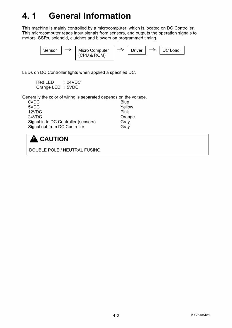
K125sm4e1 4-2
4. 1 General Information This machine is mainly controlled by a microcomputer, which is located on DC Controller. This microcomputer reads input signals from sensors, and outputs the operation signals to motors, SSRs, solenoid, clutches and blowers on programmed timing. LEDs on DC Controller lights when applied a specified DC. Red LED : 24VDC Orange LED : 5VDC Generally the color of wiring is separated depends on the voltage. 0VDC Blue 5VDC Yellow 12VDC Pink 24VDC Orange Signal in to DC Controller (sensors) Gray Signal out from DC Controller Gray
Sensor Micro Computer (CPU & ROM)
DC Load Driver
CAUTION DOUBLE POLE / NEUTRAL FUSING
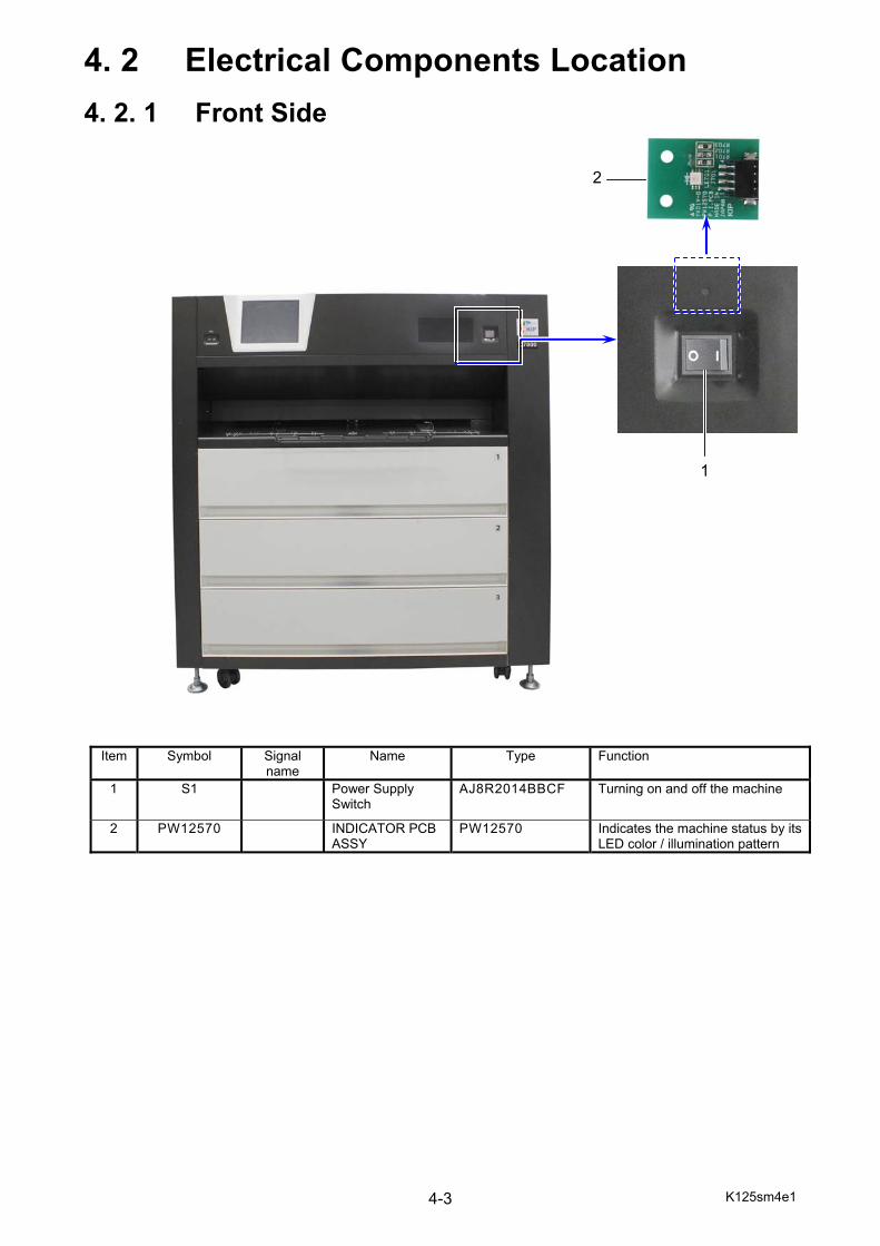
K125sm4e1 4-3
4. 2 Electrical Components Location
4. 2. 1 Front Side
Item Symbol Signal name
Name Type Function
1 S1
Power Supply Switch
AJ8R2014BBCF Turning on and off the machine
2 PW12570 INDICATOR PCB ASSY
PW12570 Indicates the machine status by its LED color / illumination pattern
2
1
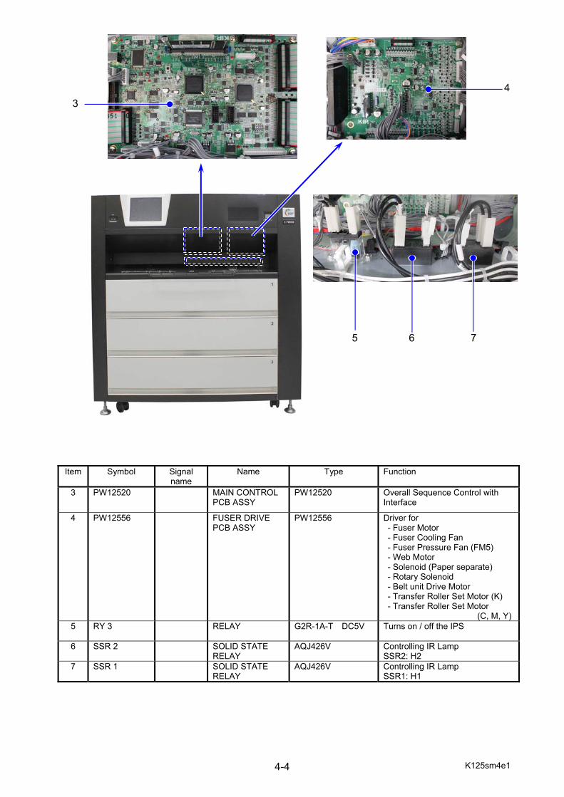
K125sm4e1 4-4
Item Symbol Signal
name Name Type Function
3 PW12520 MAIN CONTROL PCB ASSY
PW12520 Overall Sequence Control with Interface
4 PW12556 FUSER DRIVE PCB ASSY
PW12556 Driver for - Fuser Motor - Fuser Cooling Fan - Fuser Pressure Fan (FM5) - Web Motor - Solenoid (Paper separate) - Rotary Solenoid - Belt unit Drive Motor - Transfer Roller Set Motor (K) - Transfer Roller Set Motor
(C, M, Y)5 RY 3 RELAY G2R-1A-T DC5V Turns on / off the IPS
6 SSR 2 SOLID STATE
RELAY AQJ426V Controlling IR Lamp
SSR2: H2 7 SSR 1 SOLID STATE
RELAY AQJ426V Controlling IR Lamp
SSR1: H1
3 4
5 6 7
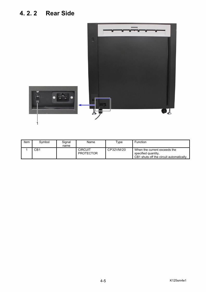
K125sm4e1 4-5
4. 2. 2 Rear Side
Item Symbol Signal name
Name Type Function
1 CB1 CIRCUIT PROTECTOR
CP32VM/20 When the current exceeds the specified quantity, CB1 shuts off the circuit automatically.
1

K125sm4e1 4-6
Item Symbol Signal name
Name Type Function
2 PW12580C COLOR SENSOR PCB ASSY (color sensor 3)
PW12580 Used for automatic adjustments of:
3 PW12580A COLOR SENSOR PCB ASSY (color sensor 1)
PW12580 - LED Head Skew Adjustment - LED Head Joint Adjustment
4 PW12580B COLOR SENSOR PCB ASSY (color sensor 2)
PW12580 - Color Registration Calibration
5 PW12580D COLOR SENSOR PCB ASSY (color sensor 4)
PW12580
6 ---- SENSOR ASSY (Toner Density Sensor Assy)
GP2TC2 Detects toner density on Belt surface.
7 DS6 SWITCH (Rear Door Switch)
D2VW-5L3-1HS-191
Detects Rear Door open.
8 PH25 SENSOR (Retract Roller Set Sensor)
LG248NL1 Detects Retract Roller set position
2
6
7
8
3 4 5

K125sm4e1 4-7
Item Symbol Signal name
Name Type Function
9 PW10730A PW10730B PW10730C PW10730D
ERS PCB ASSY PW10730
Removes negative charge from Drum at the beginning of Print Process PW10730A : K PW10730B : C PW10730C : M PW10730D : Y
9
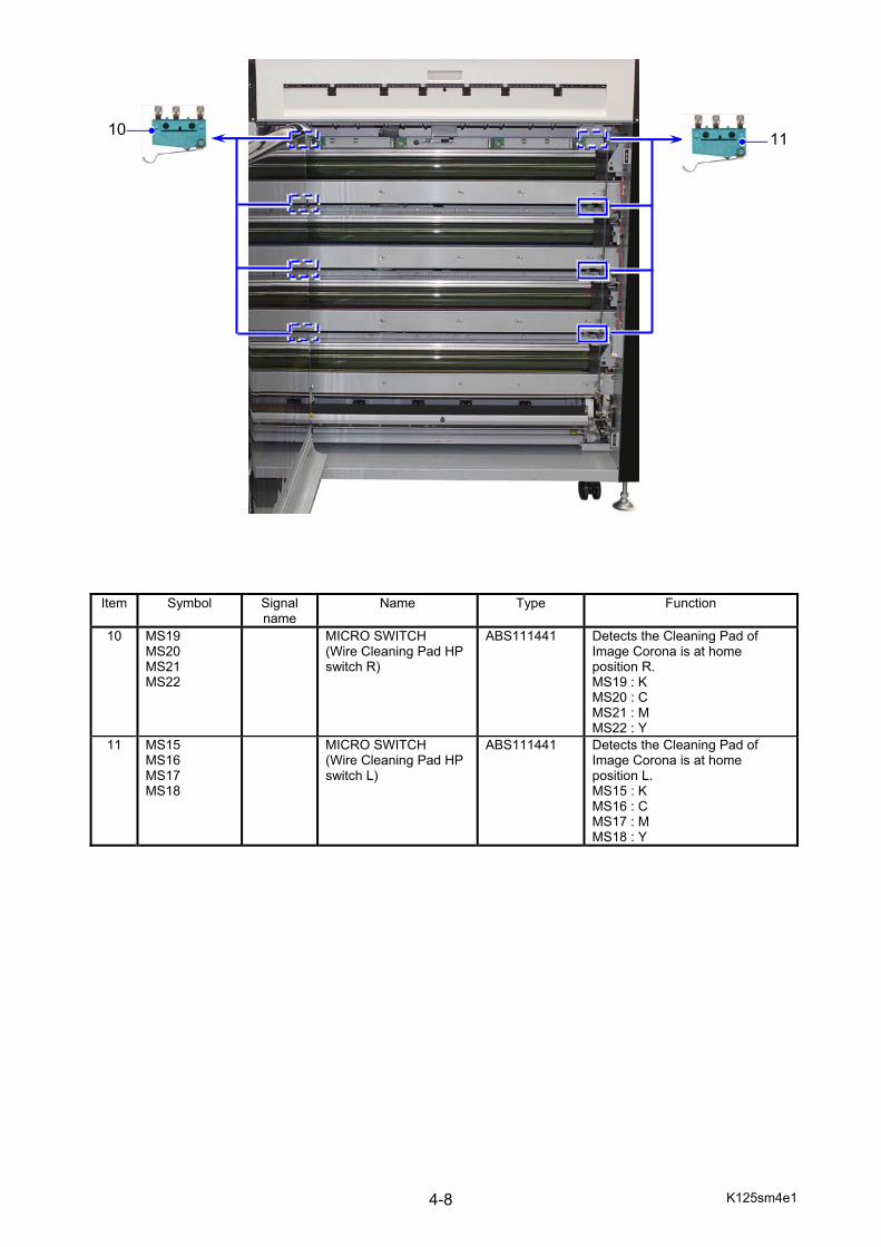
K125sm4e1 4-8
Item Symbol Signal name
Name Type Function
10
MS19 MS20 MS21 MS22
MICRO SWITCH (Wire Cleaning Pad HP switch R)
ABS111441
Detects the Cleaning Pad of Image Corona is at home position R. MS19 : K MS20 : C MS21 : M MS22 : Y
11
MS15 MS16 MS17 MS18
MICRO SWITCH (Wire Cleaning Pad HP switch L)
ABS111441
Detects the Cleaning Pad of Image Corona is at home position L. MS15 : K MS16 : C MS17 : M MS18 : Y
10 11
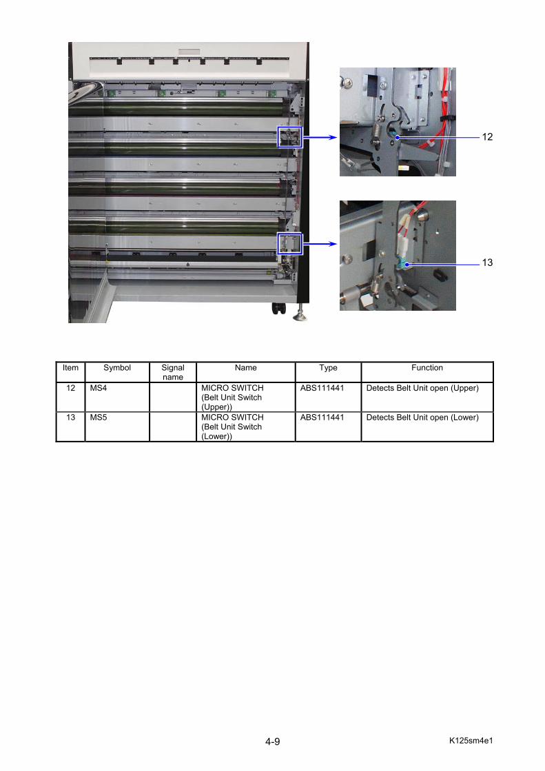
K125sm4e1 4-9
Item Symbol Signal name
Name Type Function
12 MS4 MICRO SWITCH (Belt Unit Switch (Upper))
ABS111441 Detects Belt Unit open (Upper)
13 MS5 MICRO SWITCH (Belt Unit Switch (Lower))
ABS111441 Detects Belt Unit open (Lower)
13
12
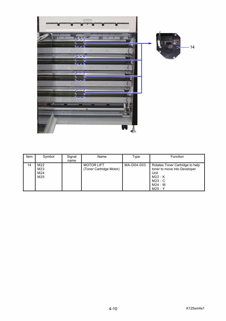
K125sm4e1 4-10
Item Symbol Signal name
Name Type Function
14 M22 M23 M24 M25
MOTOR LIFT (Toner Cartridge Motor)
MA-D04-003
Rotates Toner Cartridge to help toner to move into Developer Unit M22 : K M23 : C M24 : M M25 : Y
14
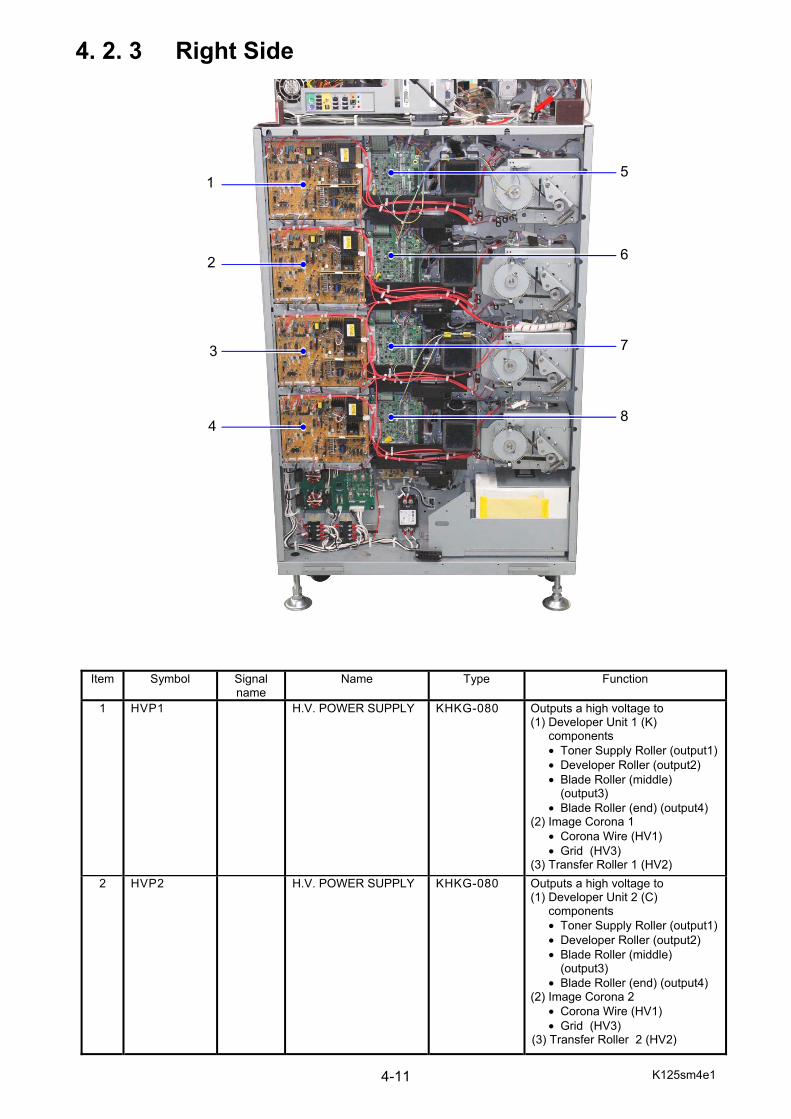
K125sm4e1 4-11
4. 2. 3 Right Side
Item Symbol Signal name
Name Type Function
1 HVP1 H.V. POWER SUPPLY KHKG-080 Outputs a high voltage to (1) Developer Unit 1 (K)
components • Toner Supply Roller (output1)• Developer Roller (output2) • Blade Roller (middle)
(output3) • Blade Roller (end) (output4)
(2) Image Corona 1 • Corona Wire (HV1) • Grid (HV3)
(3) Transfer Roller 1 (HV2) 2 HVP2 H.V. POWER SUPPLY KHKG-080 Outputs a high voltage to
(1) Developer Unit 2 (C) components • Toner Supply Roller (output1)• Developer Roller (output2) • Blade Roller (middle)
(output3) • Blade Roller (end) (output4)
(2) Image Corona 2 • Corona Wire (HV1) • Grid (HV3)
(3) Transfer Roller 2 (HV2)
1
2
3
4
5
6
7
8
K125sm4e1 4-12
Item Symbol Signal
name Name Type Function
3 HVP3 H.V. POWER SUPPLY KHKG-080 Outputs a high voltage to (1) Developer Unit 3 (M)
components • Toner Supply Roller
(output1) • Developer Roller (output2) • Blade Roller (middle)
(output3) • Blade Roller (end) (output4)
(2) Image Corona 3 • Corona Wire (HV1) • Grid (HV3)
(3) Transfer Roller 3 (HV2) 4 HVP4 H.V. POWER SUPPLY KHKG-080 Outputs a high voltage to
(1) Developer Unit 4 (Y) components • Toner Supply Roller
(output1) • Developer Roller (output2) • Blade Roller (middle)
(output3) • Blade Roller (end) (output4)
(2) Image Corona 4 • Corona Wire (HV1) • Grid (HV3)
(3) Transfer Roller 4 (HV2) 5 PW12555A
DEVE DRIVE PCB
ASSY PW12555 Driver for “Process (K)”
• Drum Motor • Toner Cartridge Motor • Dev Pressure Motor • Wire Cleaning Motor • Exhaust Fan • Cooling Fan (for DCP4) • Eraser Lamp • Fuser Pressure Fan
(FM6, FM7, FM12, FM13) • Stacker Fan (Option) • Stacker Motor (Option)
6 PW12555B DEVE DRIVE PCB ASSY
PW12555 Driver for “Process (C)” • Drum Motor • Toner Cartridge Motor • Dev Pressure Motor • Wire Cleaning Motor • Cooling Fan (for DCP3) • Eraser Lamp • Fuser Pressure Fan
(FM14, FM15) 7 PW12555C DEVE DRIVE PCB
ASSY PW12555 Driver for “Process (M)”
• Drum Motor • Toner Cartridge Motor • Dev Pressure Motor • Wire Cleaning Motor • Eraser Lamp
8 PW12555D DEVE DRIVE PCB ASSY
PW12555 Driver for “Process (Y)” • Drum Motor • Toner Cartridge Motor • Dev Pressure Motor • Wire Cleaning Motor • Eraser Lamp

K125sm4e1 4-13
Item Symbol Signal name
Name Type Function
9
FM1 FM2 FM3 FM4
FAN MOTOR (Exhaust Fan)
9GA0824P1H63
Exhausts air around Process Unit FM1 : K FM2 : C FM3 : M FM4 : Y
10 M12 M13 M14 M15
GEARED MOTOR (Drum Motor)
DGR-6236-226
Drives Drum M12 : K M13 : C M14 : M M15 : Y
10
9
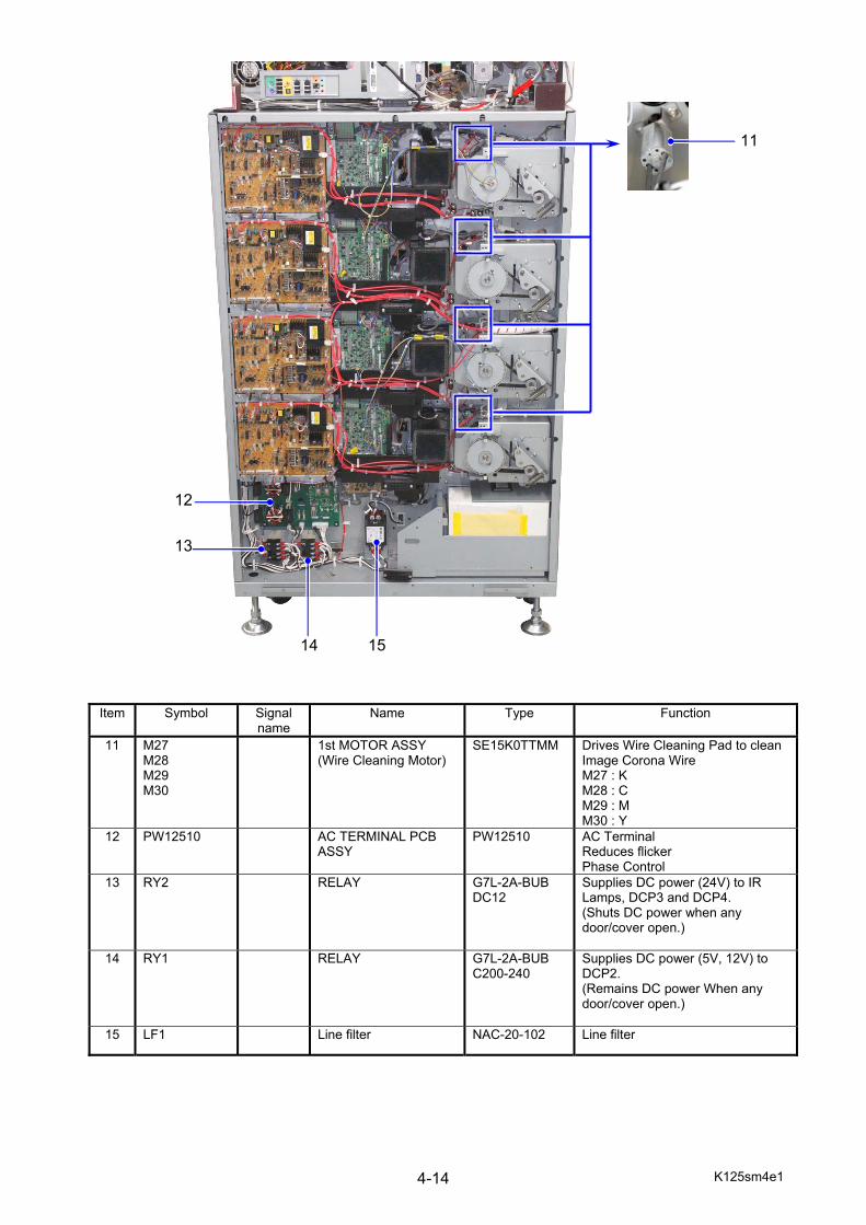
K125sm4e1 4-14
Item Symbol Signal name
Name Type Function
11
M27 M28 M29 M30
1st MOTOR ASSY (Wire Cleaning Motor)
SE15K0TTMM
Drives Wire Cleaning Pad to clean Image Corona Wire M27 : K M28 : C M29 : M M30 : Y
12 PW12510 AC TERMINAL PCB ASSY
PW12510 AC Terminal Reduces flicker Phase Control
13 RY2 RELAY G7L-2A-BUB DC12
Supplies DC power (24V) to IR Lamps, DCP3 and DCP4. (Shuts DC power when any door/cover open.)
14 RY1 RELAY G7L-2A-BUB C200-240
Supplies DC power (5V, 12V) to DCP2. (Remains DC power When any door/cover open.)
15 LF1 Line filter NAC-20-102 Line filter
11
12
13
14 15
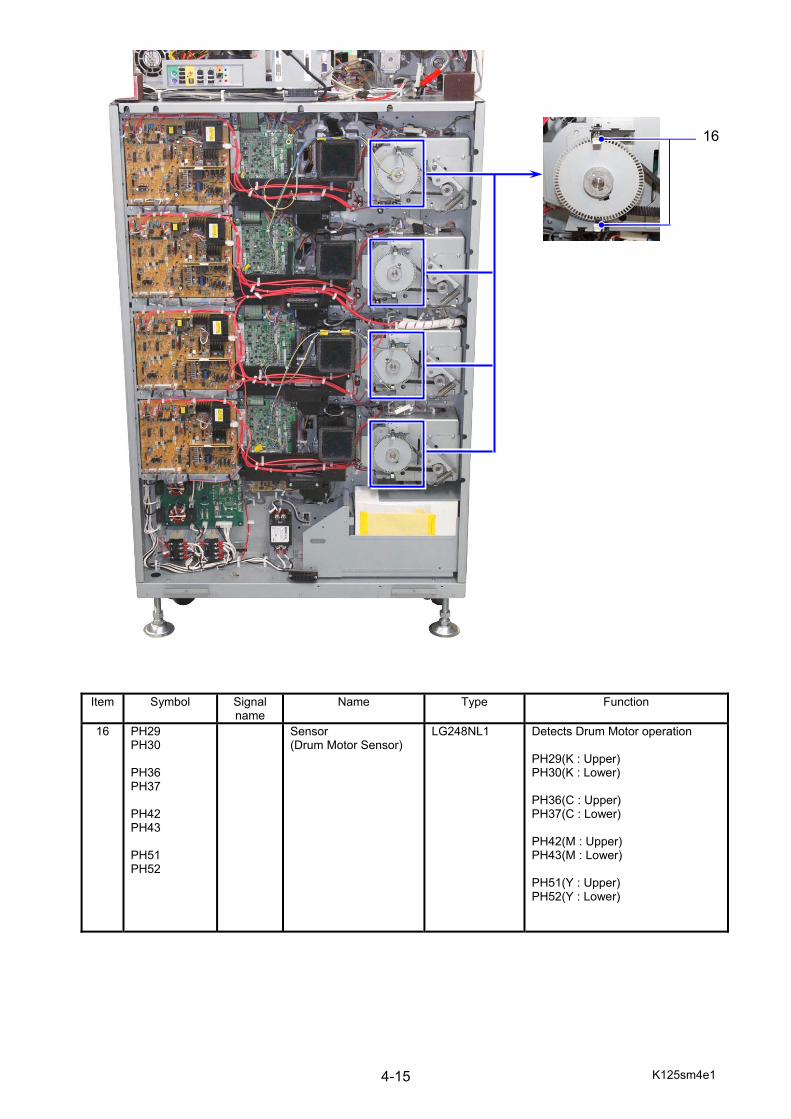
K125sm4e1 4-15
Item Symbol Signal name
Name Type Function
16 PH29 PH30 PH36 PH37 PH42 PH43 PH51 PH52
Sensor (Drum Motor Sensor)
LG248NL1 Detects Drum Motor operation PH29(K : Upper) PH30(K : Lower) PH36(C : Upper) PH37(C : Lower) PH42(M : Upper) PH43(M : Lower) PH51(Y : Upper) PH52(Y : Lower)
16
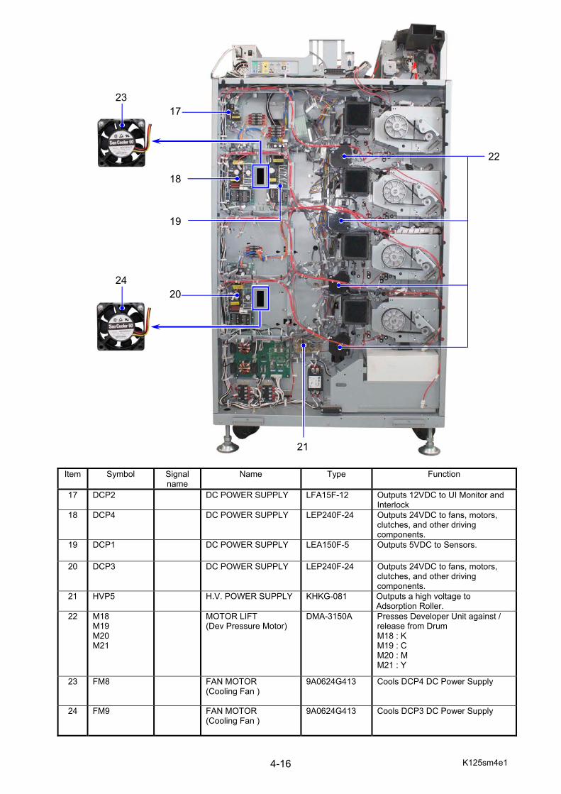
K125sm4e1 4-16
Item Symbol Signal name
Name Type Function
17 DCP2 DC POWER SUPPLY LFA15F-12 Outputs 12VDC to UI Monitor and Interlock
18 DCP4 DC POWER SUPPLY LEP240F-24 Outputs 24VDC to fans, motors, clutches, and other driving components.
19 DCP1 DC POWER SUPPLY LEA150F-5 Outputs 5VDC to Sensors.
20 DCP3 DC POWER SUPPLY LEP240F-24 Outputs 24VDC to fans, motors, clutches, and other driving components.
21 HVP5 H.V. POWER SUPPLY KHKG-081 Outputs a high voltage to Adsorption Roller.
22 M18 M19 M20 M21
MOTOR LIFT (Dev Pressure Motor)
DMA-3150A
Presses Developer Unit against / release from Drum M18 : K M19 : C M20 : M M21 : Y
23 FM8 FAN MOTOR (Cooling Fan )
9A0624G413 Cools DCP4 DC Power Supply
24 FM9 FAN MOTOR (Cooling Fan )
9A0624G413 Cools DCP3 DC Power Supply
17
18
20
21
22
24
23
19
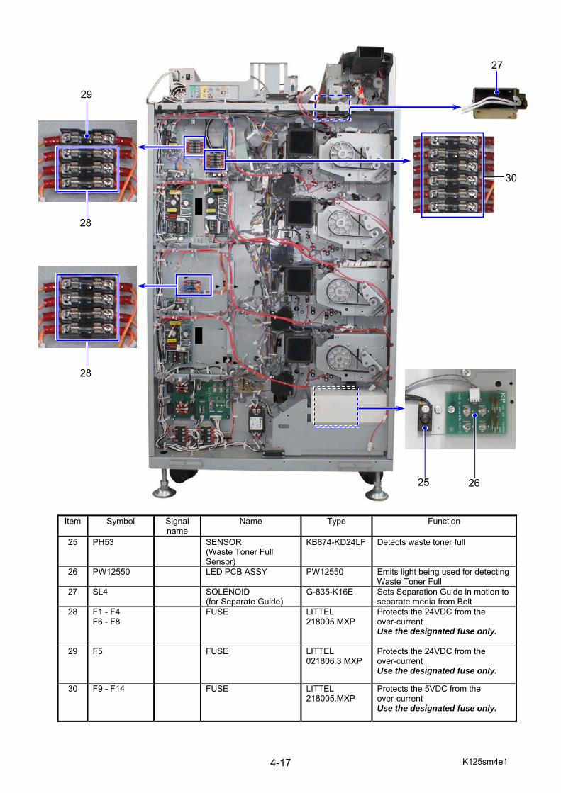
K125sm4e1 4-17
Item Symbol Signal name
Name Type Function
25 PH53 SENSOR (Waste Toner Full Sensor)
KB874-KD24LF Detects waste toner full
26 PW12550 LED PCB ASSY PW12550 Emits light being used for detecting Waste Toner Full
27 SL4 SOLENOID (for Separate Guide)
G-835-K16E Sets Separation Guide in motion to separate media from Belt
28 F1 - F4 F6 - F8
FUSE LITTEL 218005.MXP
Protects the 24VDC from the over-current Use the designated fuse only.
29 F5 FUSE LITTEL 021806.3 MXP
Protects the 24VDC from the over-current Use the designated fuse only.
30 F9 - F14
FUSE LITTEL 218005.MXP
Protects the 5VDC from the over-current Use the designated fuse only.
27
29
28
25 26
28
30
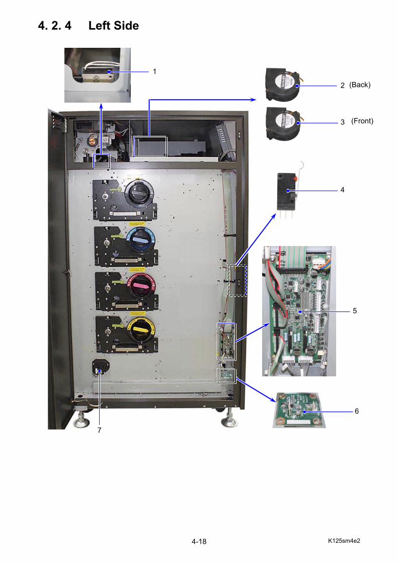
K125sm4e2 4-18
4. 2. 4 Left Side
(Back)
(Front)
1
5
4
6
7
2
3
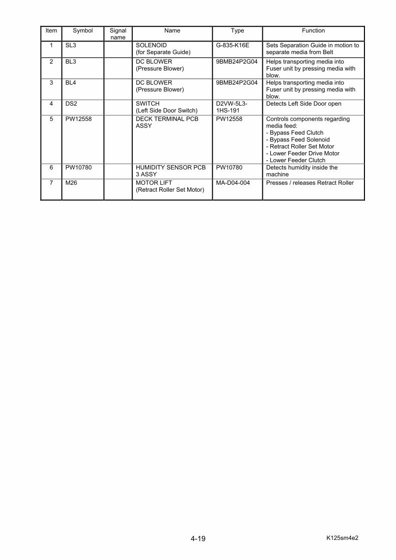
K125sm4e2 4-19
Item Symbol Signal
name Name Type Function
1 SL3 SOLENOID (for Separate Guide)
G-835-K16E Sets Separation Guide in motion to separate media from Belt
2 BL3 DC BLOWER (Pressure Blower)
9BMB24P2G04 Helps transporting media into Fuser unit by pressing media with blow.
3 BL4 DC BLOWER (Pressure Blower)
9BMB24P2G04 Helps transporting media into Fuser unit by pressing media with blow.
4 DS2 SWITCH (Left Side Door Switch)
D2VW-5L3-1HS-191
Detects Left Side Door open
5 PW12558 DECK TERMINAL PCB ASSY
PW12558 Controls components regarding media feed: - Bypass Feed Clutch - Bypass Feed Solenoid - Retract Roller Set Motor - Lower Feeder Drive Motor - Lower Feeder Clutch
6 PW10780 HUMIDITY SENSOR PCB 3 ASSY
PW10780 Detects humidity inside the machine
7 M26 MOTOR LIFT (Retract Roller Set Motor)
MA-D04-004 Presses / releases Retract Roller
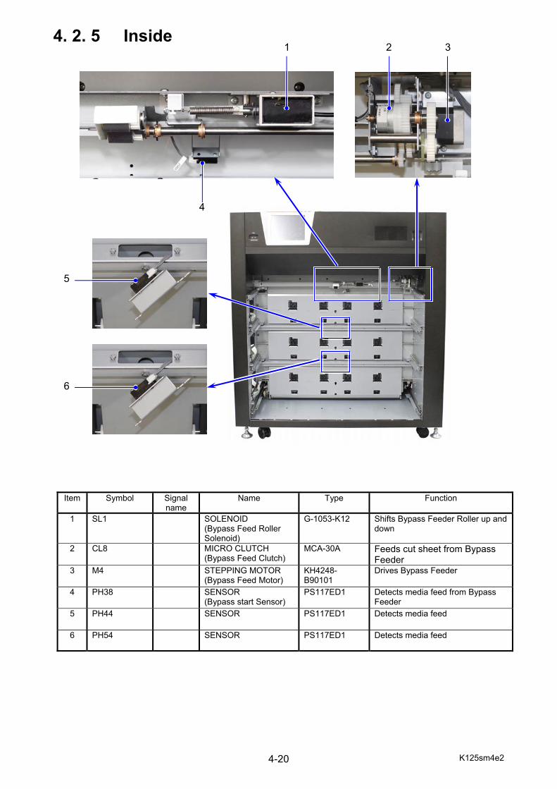
K125sm4e2 4-20
4. 2. 5 Inside
Item Symbol Signal name
Name Type Function
1 SL1 SOLENOID (Bypass Feed Roller Solenoid)
G-1053-K12 Shifts Bypass Feeder Roller up and down
2 CL8 MICRO CLUTCH (Bypass Feed Clutch)
MCA-30A Feeds cut sheet from Bypass Feeder
3 M4 STEPPING MOTOR (Bypass Feed Motor)
KH4248-B90101
Drives Bypass Feeder
4 PH38 SENSOR (Bypass start Sensor)
PS117ED1 Detects media feed from Bypass Feeder
5 PH44 SENSOR PS117ED1 Detects media feed
6 PH54 SENSOR PS117ED1 Detects media feed
1 2 3
4
5
6
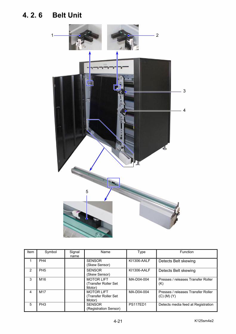
K125sm4e2 4-21
4. 2. 6 Belt Unit
Item Symbol Signal name
Name Type Function
1 PH4 SENSOR (Skew Sensor)
KI1306-AALF Detects Belt skewing
2 PH5 SENSOR (Skew Sensor)
KI1306-AALF Detects Belt skewing
3 M16 MOTOR LIFT (Transfer Roller Set Motor)
MA-D04-004 Presses / releases Transfer Roller (K)
4 M17 MOTOR LIFT (Transfer Roller Set Motor)
MA-D04-004 Presses / releases Transfer Roller (C) (M) (Y)
5 PH3 SENSOR (Registration Sensor)
PS117ED1 Detects media feed at Registration
1 2
3
4
5
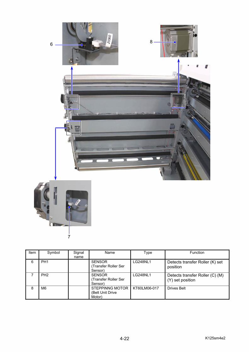
K125sm4e2 4-22
Item Symbol Signal name
Name Type Function
6 PH1 SENSOR (Transfer Roller Ser Sensor)
LG248NL1 Detects transfer Roller (K) set position
7 PH2 SENSOR (Transfer Roller Ser Sensor)
LG248NL1 Detects transfer Roller (C) (M) (Y) set position
8 M6 STEPPINNG MOTOR(Belt Unit Drive Motor)
KT60LM06-017 Drives Belt
8
6
7
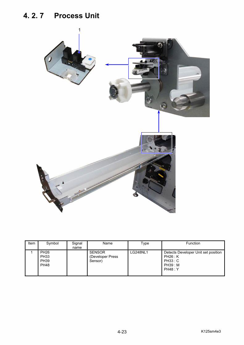
K125sm4e3 4-23
4. 2. 7 Process Unit
Item Symbol Signal name
Name Type Function
1
PH26 PH33 PH39 PH48
SENSOR (Developer Press Sensor)
LG248NL1
Detects Developer Unit set positionPH26 : K PH33 : C PH39 : M PH48 : Y
1
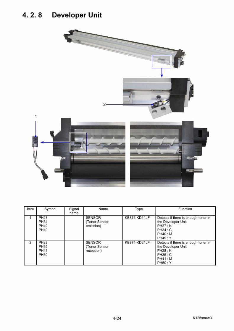
K125sm4e3 4-24
4. 2. 8 Developer Unit
Item Symbol Signal name
Name Type Function
1 PH27 PH34 PH40 PH49
SENSOR (Toner Sensor emission)
KB876-KD14LF
Detects if there is enough toner in the Developer Unit PH27 : K PH34 : C PH40 : M PH49 : Y
2 PH28 PH35 PH41 PH50
SENSOR (Toner Sensor reception)
KB874-KD24LF
Detects if there is enough toner in the Developer Unit PH28 : K PH35 : C PH41 : M PH50 : Y
2
1
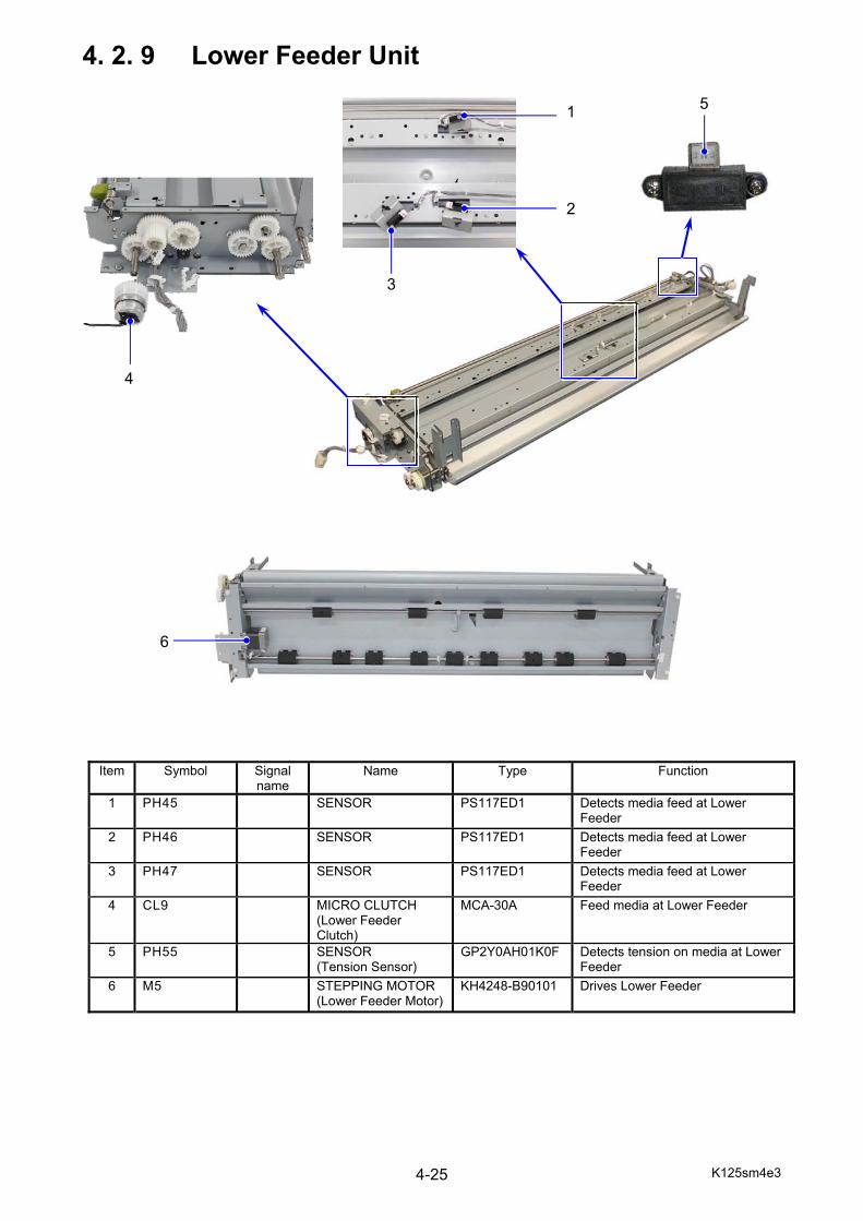
K125sm4e3 4-25
4. 2. 9 Lower Feeder Unit
Item Symbol Signal name
Name Type Function
1 PH45 SENSOR PS117ED1 Detects media feed at Lower Feeder
2 PH46 SENSOR PS117ED1 Detects media feed at Lower Feeder
3 PH47 SENSOR PS117ED1 Detects media feed at Lower Feeder
4 CL9 MICRO CLUTCH (Lower Feeder Clutch)
MCA-30A Feed media at Lower Feeder
5 PH55 SENSOR (Tension Sensor)
GP2Y0AH01K0F Detects tension on media at Lower Feeder
6 M5 STEPPING MOTOR (Lower Feeder Motor)
KH4248-B90101 Drives Lower Feeder
2
1
3
4
5
6
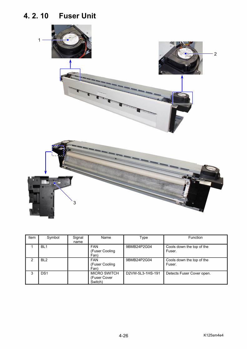
K125sm4e4 4-26
4. 2. 10 Fuser Unit
Item Symbol Signal name
Name Type Function
1 BL1 FAN (Fuser Cooling Fan)
9BMB24P2G04 Cools down the top of the Fuser.
2 BL2 FAN (Fuser Cooling Fan)
9BMB24P2G04 Cools down the top of the Fuser.
3 DS1 MICRO SWITCH (Fuser Cover Switch)
D2VW-5L3-1HS-191 Detects Fuser Cover open.
1
3
2
3
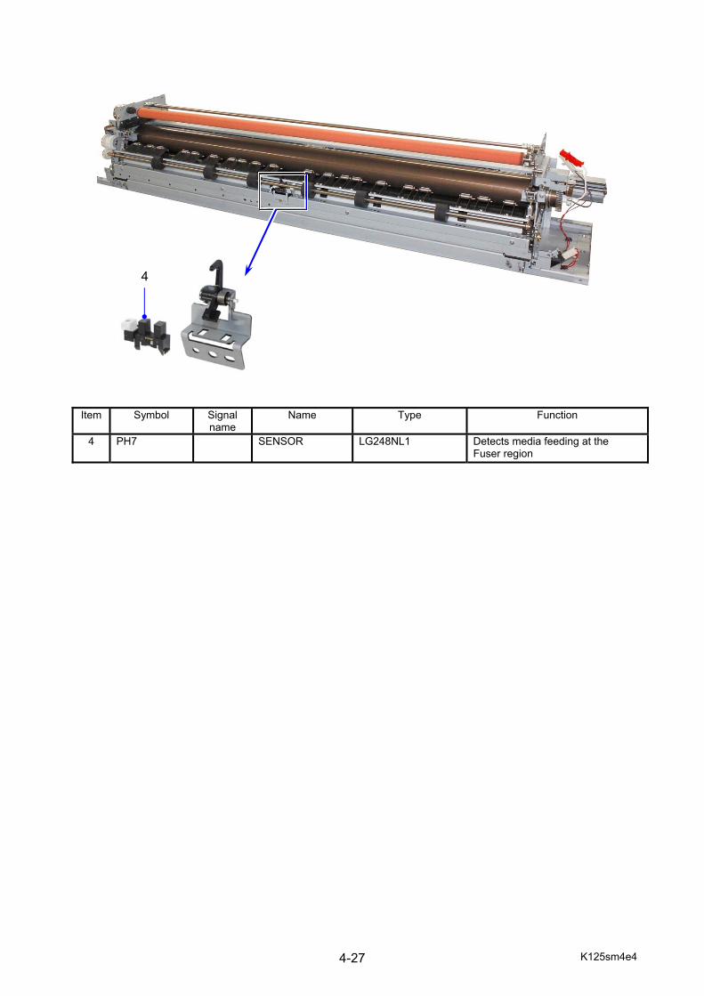
K125sm4e4 4-27
Item Symbol Signal name
Name Type Function
4 PH7 SENSOR LG248NL1 Detects media feeding at the Fuser region
4
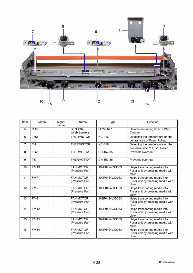
K125sm4e4 4-28
Item Symbol Signal name
Name Type Function
5 PH6 SENSOR (Web Sensor)
LG248NL1 Detects remaining level of Web Cleaner
6 TH2 THERMISTOR NC-F16 Detecting the temperature on the central area of Fuser Roller.
7 TH1 THERMISTOR NC-F16 Detecting the temperature on the non drive side of Fuser Roller.
8 TS2 THERMOSTAT CH-152-35 Prevents overheat
9 TS1 THERMOSTAT CH-152-35 Prevents overheat
10 FM13 FAN MOTOR (Pressure Fan)
109P0424J3D053 Helps transporting media into Fuser unit by pressing media with blow.
11 FM7 FAN MOTOR (Pressure Fan)
109P0424J3D053 Helps transporting media into Fuser unit by pressing media with blow.
12 FM5 FAN MOTOR (Pressure Fan)
109P0424J3D053 Helps transporting media into Fuser unit by pressing media with blow.
13 FM6 FAN MOTOR (Pressure Fan)
109P0424J3D053 Helps transporting media into Fuser unit by pressing media with blow.
14 FM12 FAN MOTOR (Pressure Fan)
109P0424J3D053 Helps transporting media into Fuser unit by pressing media with blow.
15 FM15 FAN MOTOR (Pressure Fan)
109P0424J3D053 Helps transporting media into Fuser unit by pressing media with blow.
16 FM14 FAN MOTOR (Pressure Fan)
109P0424J3D053 Helps transporting media into Fuser unit by pressing media with blow.
10 11 12 13 14 15 16
7 8
6 9
5
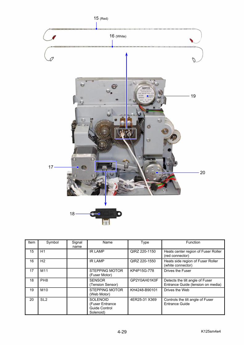
K125sm4e4 4-29
Item Symbol Signal name
Name Type Function
15 H1 IR LAMP QIRZ 220-1150 Heats center region of Fuser Roller(red connector)
16 H2 IR LAMP QIRZ 220-1550 Heats side region of Fuser Roller (white connector)
17 M11 STEPPING MOTOR (Fuser Motor)
KP4P15G-778 Drives the Fuser
18 PH8 SENSOR (Tension Sensor)
GP2Y0AH01K0F Detects the tilt angle of Fuser Entrance Guide (tension on media)
19 M10 STEPPING MOTOR (Web Motor)
KH4248-B90101 Drives the Web
20 SL2 SOLENOID (Fuser Entrance Guide Control Solenoid)
4ER25-31 X369 Controls the tilt angle of Fuser Entrance Guide
17
18
20
15 (Red)
16 (White)
19
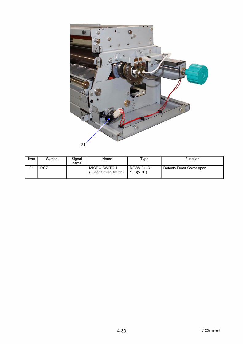
K125sm4e4 4-30
Item Symbol Signal name
Name Type Function
21 DS7 MICRO SWITCH (Fuser Cover Switch)
D2VW-01L3-1HS(VDE)
Detects Fuser Cover open.
21
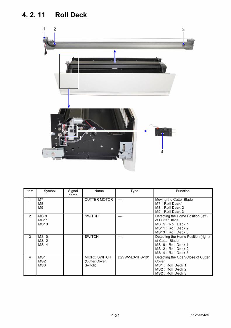
K125sm4e5 4-31
4. 2. 11 Roll Deck
Item Symbol Signal name
Name Type Function
1 M7 M8 M9
CUTTER MOTOR
---- Moving the Cutter BladeM7 : Roll Deck1 M8 : Roll Deck 2 M9 : Roll Deck 3
2 MS 9 MS11 MS13
SWITCH ---- Detecting the Home Position (left) of Cutter Blade. MS 9 : Roll Deck 1 MS11 : Roll Deck 2 MS13 : Roll Deck 3
3 MS10 MS12 MS14
SWITCH ---- Detecting the Home Position (right) of Cutter Blade. MS10 : Roll Deck 1 MS12 : Roll Deck 2 MS14 : Roll Deck 3
4 MS1 MS2 MS3
MICRO SWITCH (Cutter Cover Switch)
D2VW-5L3-1HS-191 Detecting the Open/Close of Cutter Cover. MS1 : Roll Deck 1 MS2 : Roll Deck 2 MS2 : Roll Deck 3
1 2 3
4

K125sm4e5 4-32
Item Symbol Signal name
Name Type Function
5 MS6 MS7 MS8
SWITCH (Initial Cut Switch)
CS1A-B2CA Starts an initial cut. MS6 : Roll Deck 1 MS7 : Roll Deck 2 MS8 : Roll Deck 3
6 CL1 CL3 CL5
MICRO CLUTCH (Roll feed Clutch)
MCA-30A Feeding the roll media forwardCL1 : Roll Deck 1 CL3 : Roll Deck 2 CL5 : Roll Deck 3
7 CL2 CL4 CL6
MICRO CLUTCH (Registration Clutch)
MCA-30A Rewinding the roll mediaCL2 : Roll Deck 1 CL4 : Roll Deck 2 CL6 : Roll Deck 3
8 PH12 PH17 PH23
SENSOR (Media remaining sensor)
LG248NL1 Detects remaining amount of media with a clock pulse generated by Roll Deck Spool. PH12 : Roll Deck 1 PH17 : Roll Deck 2 PH23 : Roll Deck 3
5
7
6
8
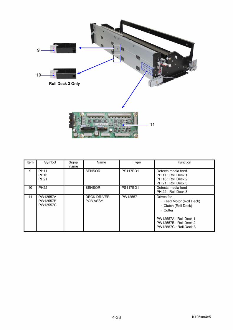
K125sm4e5 4-33
Item Symbol Signal name
Name Type Function
9 PH11 PH16 PH21
SENSOR PS117ED1 Detects media feed PH 11 : Roll Deck 1 PH 16 : Roll Deck 2 PH 21 : Roll Deck 3
10 PH22 SENSOR PS117ED1 Detects media feed PH 22 : Roll Deck 3
11 PW12557A PW12557B PW12557C
DECK DRIVER PCB ASSY
PW12557 Drives for ・Feed Motor (Roll Deck) ・Clutch (Roll Deck) ・Cutter
PW12557A : Roll Deck 1 PW12557B : Roll Deck 2 PW12557C : Roll Deck 3
9
10
11
Roll Deck 3 Only
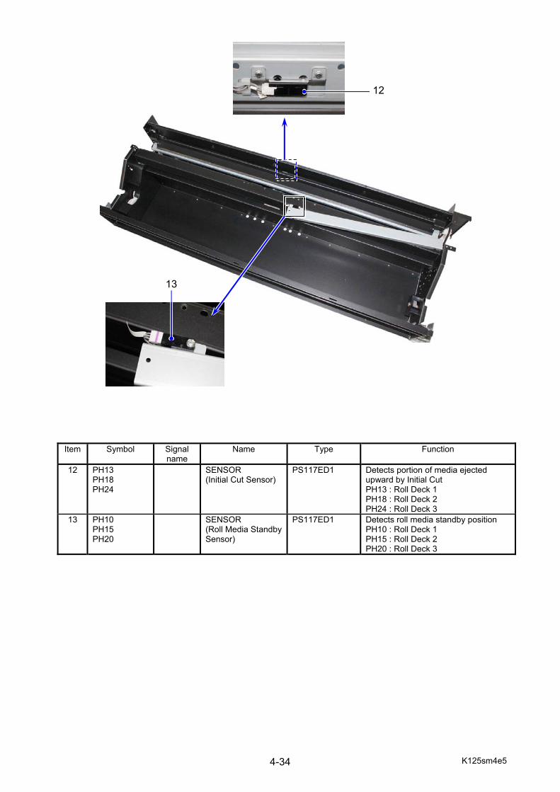
K125sm4e5 4-34
Item Symbol Signal name
Name Type Function
12 PH13 PH18 PH24
SENSOR (Initial Cut Sensor)
PS117ED1 Detects portion of media ejected upward by Initial Cut PH13 : Roll Deck 1 PH18 : Roll Deck 2 PH24 : Roll Deck 3
13 PH10 PH15 PH20
SENSOR (Roll Media Standby Sensor)
PS117ED1
Detects roll media standby position PH10 : Roll Deck 1 PH15 : Roll Deck 2 PH20 : Roll Deck 3
12
13
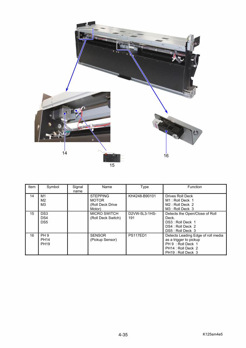
K125sm4e5 4-35
Item Symbol Signal name
Name Type Function
14 M1 M2 M3
STEPPING MOTOR (Roll Deck Drive Motor)
KH4248-B90101 Drives Roll Deck M1 : Roll Deck 1 M2 : Roll Deck 2 M3 : Roll Deck 3
15 DS3 DS4 DS5
MICRO SWITCH (Roll Deck Switch)
D2VW-5L3-1HS-191
Detects the Open/Close of Roll Deck. DS3 : Roll Deck 1 DS4 : Roll Deck 2 DS5 : Roll Deck 3
16 PH 9 PH14 PH19
SENSOR (Pickup Sensor)
PS117ED1 Detects Leading Edge of roll media as a trigger to pickup PH 9 : Roll Deck 1 PH14 : Roll Deck 2 PH19 : Roll Deck 3
14
15
16
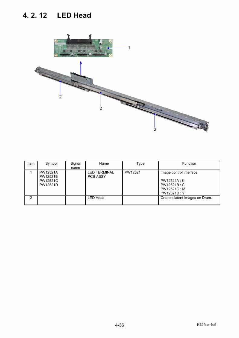
K125sm4e5 4-36
4. 2. 12 LED Head
Item Symbol Signal name
Name Type Function
1 PW12521A PW12521B PW12521C PW12521D
LED TERMINAL PCB ASSY
PW12521 Image control interface PW12521A : K PW12521B : C PW12521C : M PW12521D : Y
2 LED Head Creates latent Images on Drum.
1
2
2
2
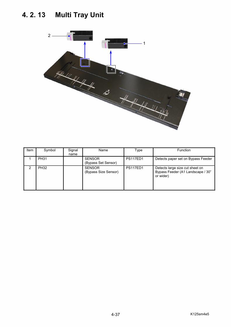
K125sm4e5 4-37
4. 2. 13 Multi Tray Unit
Item Symbol Signal name
Name Type Function
1 PH31 SENSOR (Bypass Set Sensor)
PS117ED1 Detects paper set on Bypass Feeder
2 PH32 SENSOR (Bypass Size Sensor)
PS117ED1 Detects large size cut sheet on Bypass Feeder (A1 Landscape / 30” or wider)
1
2
K125sm4e6 4-38
4. 3 Check & Adjustment of HV Power Supply The High Voltage Power Supply PCBs are well adjusted before shipment, so basically it is unnecessary to check or readjust them in the market. If you will like to check the output for some reason such as troubleshooting purpose, please do it as instructed in this section.
Checking Item Reference page Image Corona (Output voltage to Image Corona) 4-39 Image Corona (Analog voltage to Image Corona) 4-42 Grid Plate (Output voltage to Grid Plate) 4-45 Grid Plate (Analog voltage to Grid Plate) 4-48 Transfer Roller (Output voltage to Transfer Roller) 4-51 Transfer Roller (Analog voltage to Transfer Roller) 4-56 Developer Bias (Output voltage to Developer Roller) 4-61 Developer Bias (Analog voltage to Developer Roller) 4-66 Voltage gap between Developer Roller & Toner Supply Roller 4-71 Voltage gap between Developer Roller & Blade Roller (Center) 4-75 Voltage gap between Developer Roller & Blade Roller (Both sides) 4-79 Media Charge Roller (Output voltage to Media Charge Roller) 4-82 Media Charge Roller (Analog voltage to Media Charge Roller) 4-86
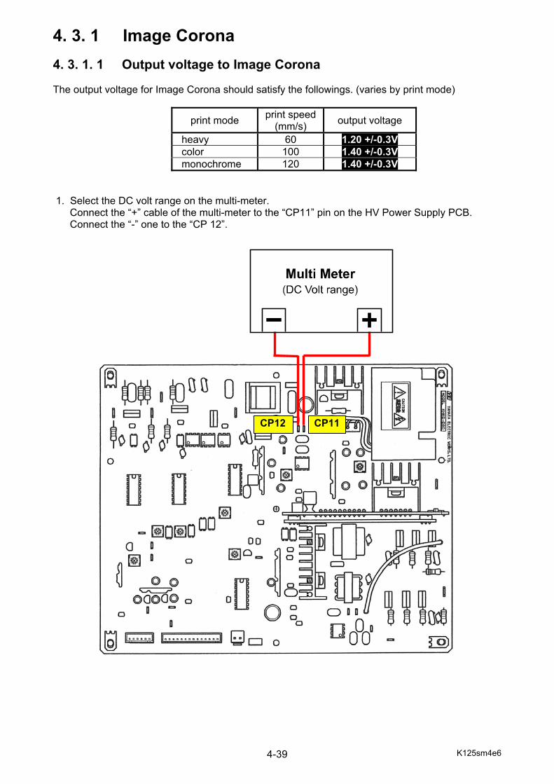
K125sm4e6 4-39
4. 3. 1 Image Corona 4. 3. 1. 1 Output voltage to Image Corona The output voltage for Image Corona should satisfy the followings. (varies by print mode)
print mode print speed(mm/s) output voltage
heavy 60 1.20 +/-0.3V color 100 1.40 +/-0.3V monochrome 120 1.40 +/-0.3V
1. Select the DC volt range on the multi-meter.
Connect the “+” cable of the multi-meter to the “CP11” pin on the HV Power Supply PCB. Connect the “-” one to the “CP 12”.
CP11CP12
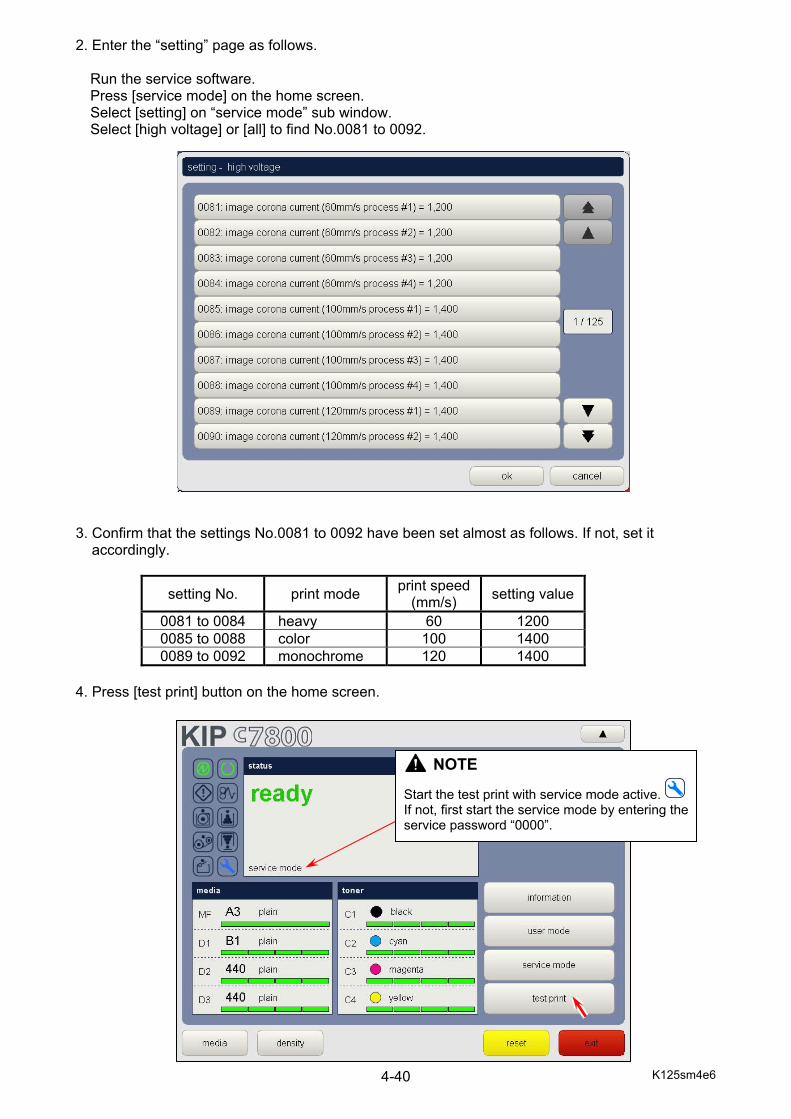
K125sm4e6 4-40
2. Enter the “setting” page as follows. Run the service software. Press [service mode] on the home screen. Select [setting] on “service mode” sub window. Select [high voltage] or [all] to find No.0081 to 0092.
3. Confirm that the settings No.0081 to 0092 have been set almost as follows. If not, set it
accordingly.
setting No. print mode print speed(mm/s) setting value
0081 to 0084 heavy 60 1200 0085 to 0088 color 100 1400 0089 to 0092 monochrome 120 1400
4. Press [test print] button on the home screen.
NOTE
Start the test print with service mode active. If not, first start the service mode by entering the service password “0000”.
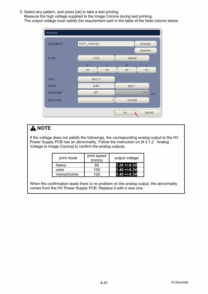
K125sm4e6 4-41
5. Select any pattern, and press [ok] to take a test printing. Measure the high voltage supplied to the Image Corona during test printing. The output voltage must satisfy the requirement said in the table of the Note column below.
NOTE If the voltage does not satisfy the followings, the corresponding analog output to the HV Power Supply PCB has an abnormality. Follow the instruction on [4.3.1.2 Analog Voltage to Image Corona] to confirm the analog outputs.
print mode print speed(mm/s) output voltage
heavy 60 1.20 +/-0.3V color 100 1.40 +/-0.3V monochrome 120 1.40 +/-0.3V
When the confirmation leads there is no problem on the analog output, the abnormality comes from the HV Power Supply PCB. Replace it with a new one.

K125sm4e6 4-42
4. 3. 1. 2 Analog voltage to Image Corona The analog voltage supplied to the HV Power Supply PCB adjusts the output voltage to the Image Corona. Check these voltages in the following way. 1. Connect the “+” cable of the multi-meter to the 7th pin from right of the connector CN302 on the
HV Power Supply PCB. Connect the “-” one to the ground. Select the DC volt range on the multi-meter. This is for checking the analog voltage to the HV Power Supply.
CN302, 7th from right
GND

K125sm4e6 4-43
2. Enter the “setting” page as follows. Run the service software. Press [service mode] on the home screen. Select [setting] on “service mode” sub window. Select [high voltage] or [all] to find No.0081 to 0092.
3. Confirm that the settings No.0081 to 0092 have been set almost as follows. If not, set it
accordingly.
setting No. print mode print speed(mm/s) setting value
0081 to 0084 heavy 60 1200 0085 to 0088 color 100 1400 0089 to 0092 monochrome 120 1400
4. Press [test print] button on the home screen.
NOTE
Start the test print with service mode active. If not, first start the service mode by entering the service password “0000”.
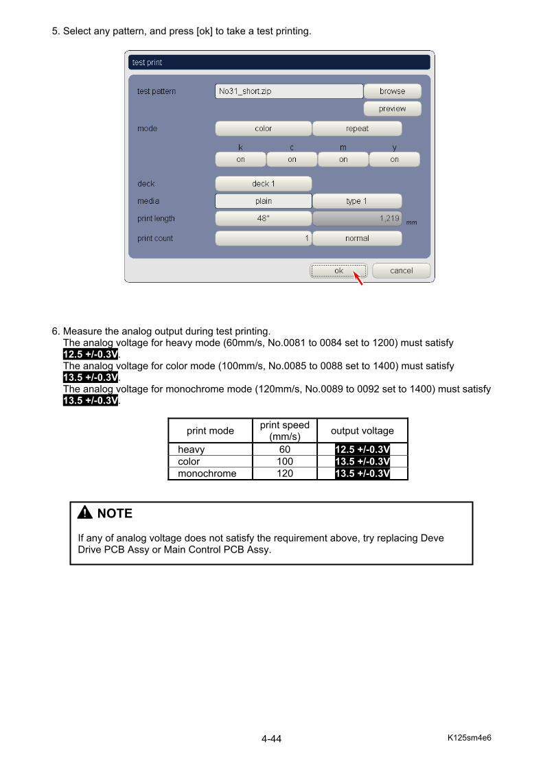
K125sm4e6 4-44
5. Select any pattern, and press [ok] to take a test printing. 6. Measure the analog output during test printing.
The analog voltage for heavy mode (60mm/s, No.0081 to 0084 set to 1200) must satisfy 12.5 +/-0.3V. The analog voltage for color mode (100mm/s, No.0085 to 0088 set to 1400) must satisfy 13.5 +/-0.3V. The analog voltage for monochrome mode (120mm/s, No.0089 to 0092 set to 1400) must satisfy 13.5 +/-0.3V.
print mode print speed(mm/s) output voltage
heavy 60 12.5 +/-0.3V color 100 13.5 +/-0.3V monochrome 120 13.5 +/-0.3V
NOTE If any of analog voltage does not satisfy the requirement above, try replacing Deve Drive PCB Assy or Main Control PCB Assy.
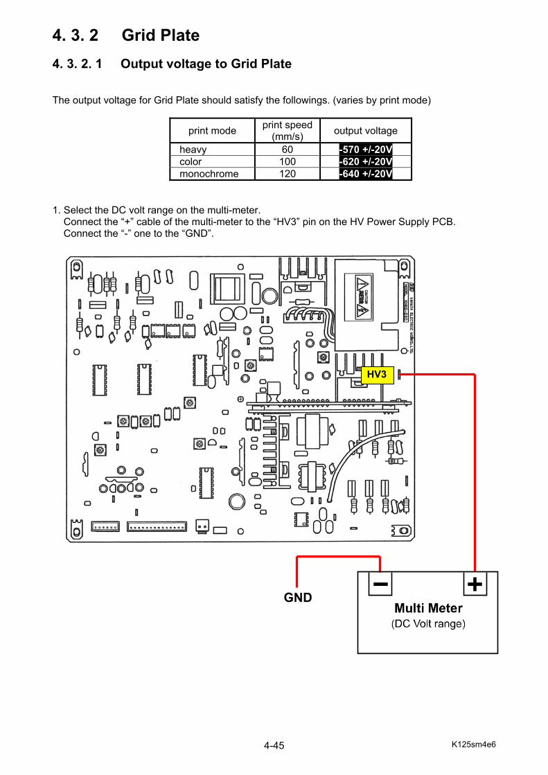
K125sm4e6 4-45
4. 3. 2 Grid Plate 4. 3. 2. 1 Output voltage to Grid Plate The output voltage for Grid Plate should satisfy the followings. (varies by print mode)
print mode print speed(mm/s) output voltage
heavy 60 -570 +/-20V color 100 -620 +/-20V monochrome 120 -640 +/-20V
1. Select the DC volt range on the multi-meter.
Connect the “+” cable of the multi-meter to the “HV3” pin on the HV Power Supply PCB. Connect the “-” one to the “GND”.
HV3
GND

K125sm4e6 4-46
2. Run the service software. Enter the “setting” page as follows. Press [service mode] on the home screen. Select [setting] on “service mode” sub window. Select [high voltage] or [all] to find No.0093 to 0104.
3. Confirm that the settings No.0093 to 0104 have been set almost as follows. If not, set it
accordingly.
setting No. print mode print speed(mm/s) setting value
0093 to 0096 heavy 60 570 0097 to 0100 color 100 620 0101 to 0104 monochrome 120 640
4. Press [test print] button on the home screen.
NOTE
Start the test print with service mode active. If not, first start the service mode by entering the service password “0000”.
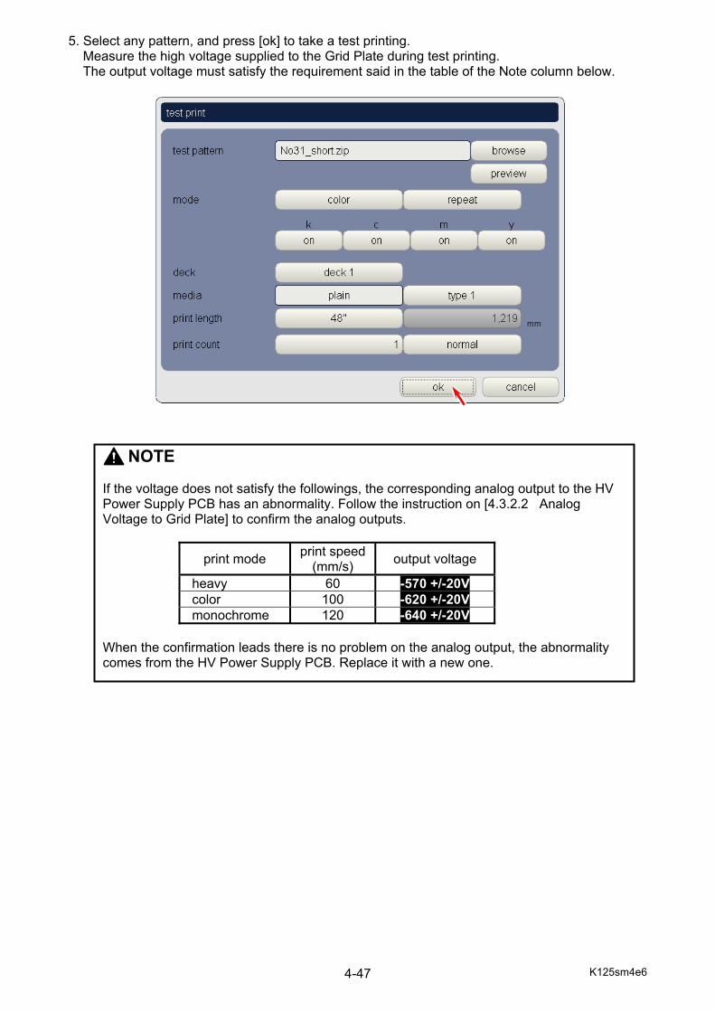
K125sm4e6 4-47
5. Select any pattern, and press [ok] to take a test printing. Measure the high voltage supplied to the Grid Plate during test printing. The output voltage must satisfy the requirement said in the table of the Note column below.
NOTE If the voltage does not satisfy the followings, the corresponding analog output to the HV Power Supply PCB has an abnormality. Follow the instruction on [4.3.2.2 Analog Voltage to Grid Plate] to confirm the analog outputs.
print mode print speed(mm/s) output voltage
heavy 60 -570 +/-20V color 100 -620 +/-20V monochrome 120 -640 +/-20V
When the confirmation leads there is no problem on the analog output, the abnormality comes from the HV Power Supply PCB. Replace it with a new one.
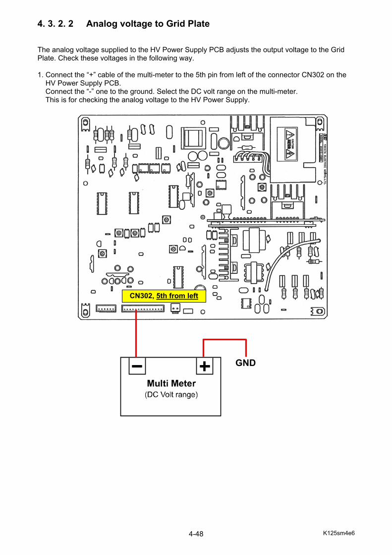
K125sm4e6 4-48
4. 3. 2. 2 Analog voltage to Grid Plate The analog voltage supplied to the HV Power Supply PCB adjusts the output voltage to the Grid Plate. Check these voltages in the following way. 1. Connect the “+” cable of the multi-meter to the 5th pin from left of the connector CN302 on the
HV Power Supply PCB. Connect the “-” one to the ground. Select the DC volt range on the multi-meter. This is for checking the analog voltage to the HV Power Supply.
GND
CN302, 5th from left
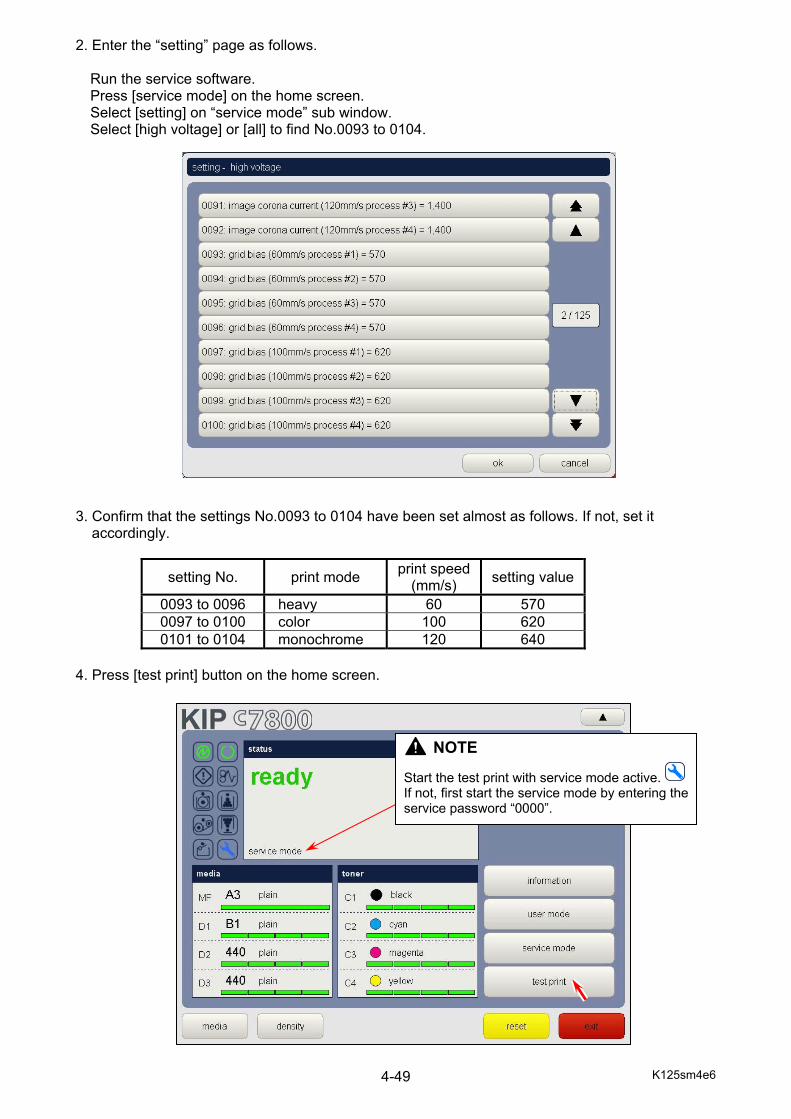
K125sm4e6 4-49
2. Enter the “setting” page as follows. Run the service software. Press [service mode] on the home screen. Select [setting] on “service mode” sub window. Select [high voltage] or [all] to find No.0093 to 0104.
3. Confirm that the settings No.0093 to 0104 have been set almost as follows. If not, set it
accordingly.
setting No. print mode print speed(mm/s) setting value
0093 to 0096 heavy 60 570 0097 to 0100 color 100 620 0101 to 0104 monochrome 120 640
4. Press [test print] button on the home screen.
NOTE
Start the test print with service mode active. If not, first start the service mode by entering the service password “0000”.
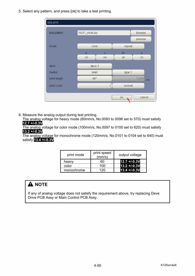
K125sm4e6 4-50
5. Select any pattern, and press [ok] to take a test printing. 6. Measure the analog output during test printing.
The analog voltage for heavy mode (60mm/s, No.0093 to 0096 set to 570) must satisfy 12.7 +/-0.3V. The analog voltage for color mode (100mm/s, No.0097 to 0100 set to 620) must satisfy 13.2 +/-0.3V. The analog voltage for monochrome mode (120mm/s, No.0101 to 0104 set to 640) must satisfy 13.4 +/-0.3V.
print mode print speed(mm/s) output voltage
heavy 60 12.7 +/-0.3V color 100 13.2 +/-0.3V monochrome 120 13.4 +/-0.3V
NOTE If any of analog voltage does not satisfy the requirement above, try replacing Deve Drive PCB Assy or Main Control PCB Assy.
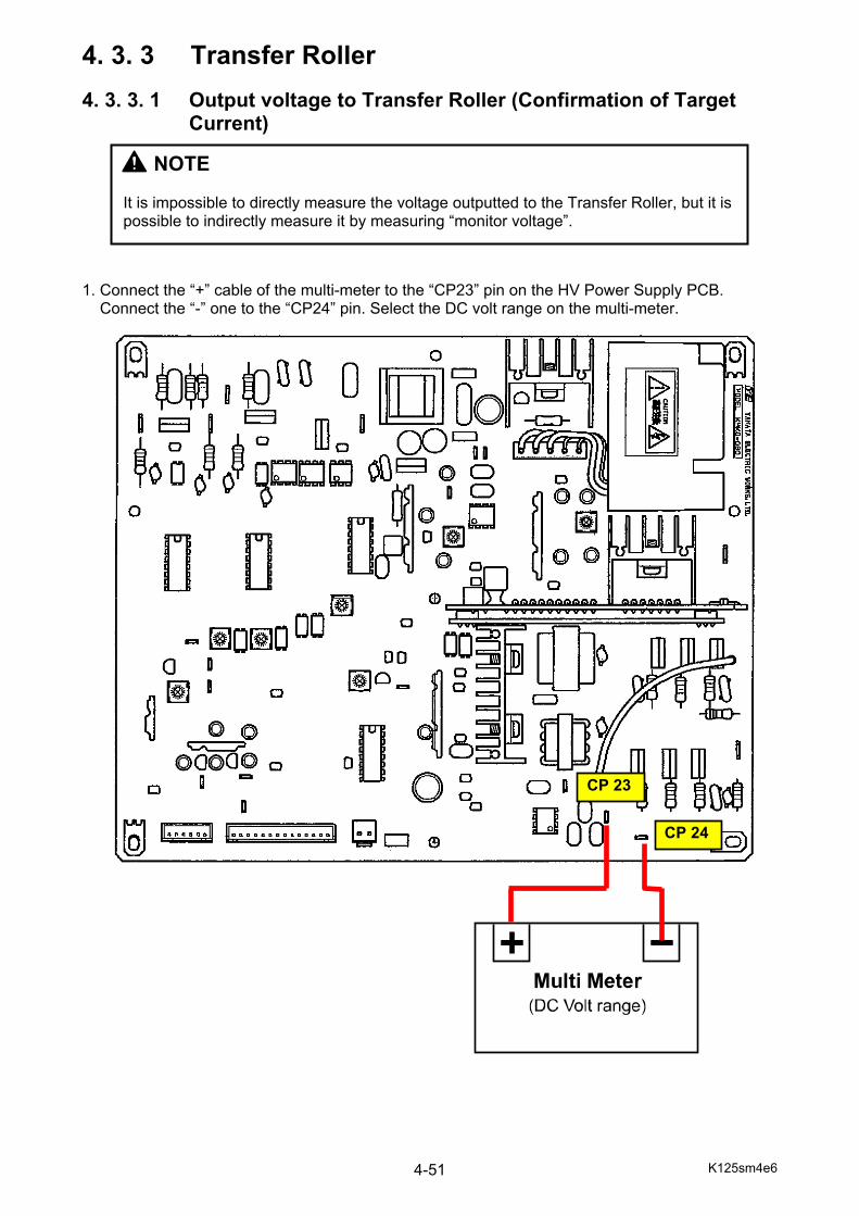
K125sm4e6 4-51
4. 3. 3 Transfer Roller 4. 3. 3. 1 Output voltage to Transfer Roller (Confirmation of Target Current) 1. Connect the “+” cable of the multi-meter to the “CP23” pin on the HV Power Supply PCB. Connect the “-” one to the “CP24” pin. Select the DC volt range on the multi-meter.
NOTE It is impossible to directly measure the voltage outputted to the Transfer Roller, but it is possible to indirectly measure it by measuring “monitor voltage”.
CP 24
CP 23

K125sm4e6 4-52
2. Run the service software. - Press [service mode] on the home screen. - Select [setting] on “service mode” sub window. - Select [high voltage] - Find item No.0321 to 0324 (transfer roller voltage), and be sure that all of them are set to
500. If not, set them to 500. 3. In the same “high voltage” category page, find item No. 2453 to 2455 and be sure that they are set to the following values respectively. 2453 auto adjust transfer voltage target current (60mm/s) : 40 2454 auto adjust transfer voltage target current (100mm/s) : 70 2455 auto adjust transfer voltage target current (120mm/s) : 85
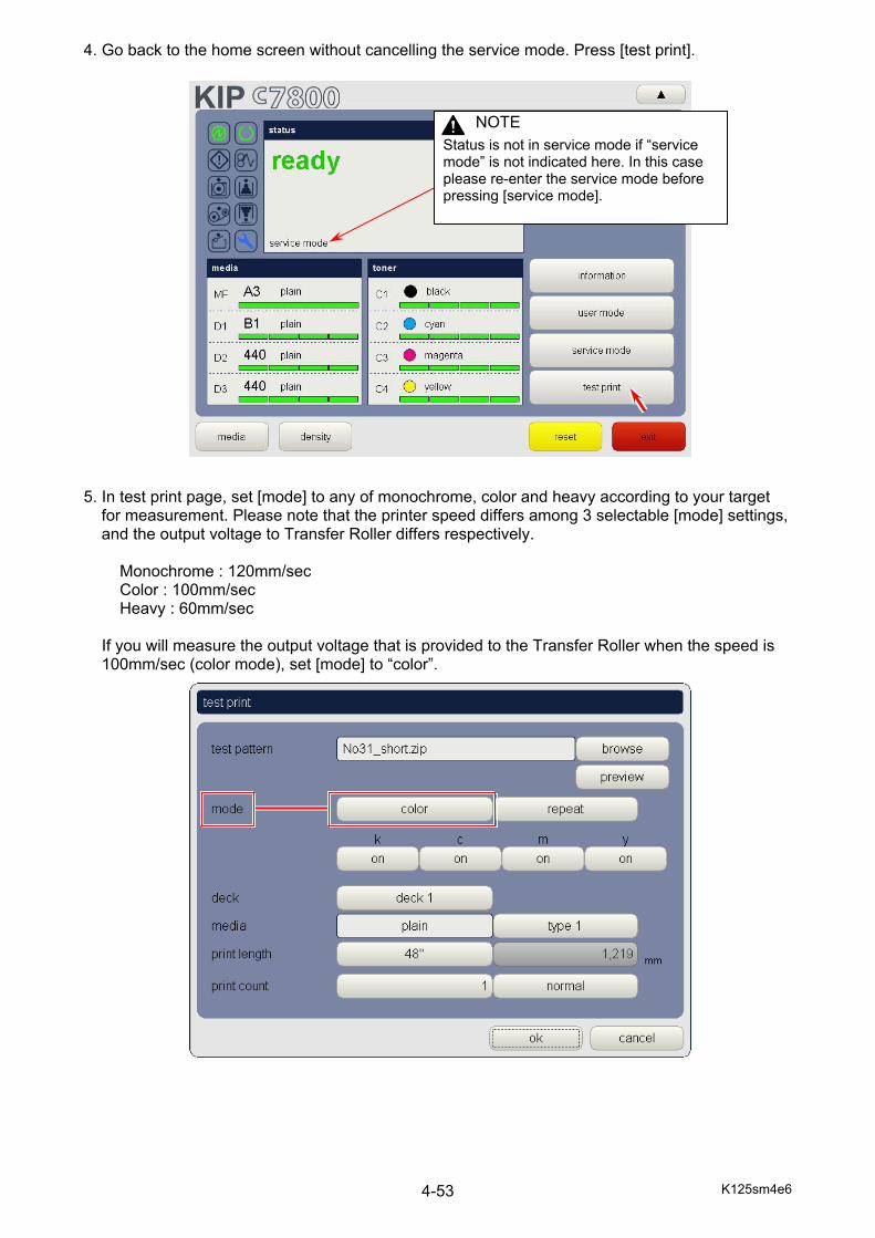
K125sm4e6 4-53
4. Go back to the home screen without cancelling the service mode. Press [test print]. 5. In test print page, set [mode] to any of monochrome, color and heavy according to your target
for measurement. Please note that the printer speed differs among 3 selectable [mode] settings, and the output voltage to Transfer Roller differs respectively.
Monochrome : 120mm/sec Color : 100mm/sec Heavy : 60mm/sec If you will measure the output voltage that is provided to the Transfer Roller when the speed is
100mm/sec (color mode), set [mode] to “color”.
NOTE
Status is not in service mode if “service mode” is not indicated here. In this case please re-enter the service mode before pressing [service mode].
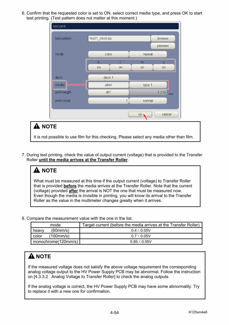
K125sm4e6 4-54
6. Confirm that the requested color is set to ON, select correct media type, and press OK to start test printing. (Test pattern does not matter at this moment.)
7. During test printing, check the value of output current (voltage) that is provided to the Transfer
Roller until the media arrives at the Transfer Roller. 8. Compare the measurement value with the one in the list.
mode Target current (before the media arrives at the Transfer Roller)heavy (60mm/s) 0.4±0.05V color (100mm/s) 0.7±0.05V monochrome(120mm/s) 0.85±0.05V
NOTE What must be measured at this time if the output current (voltage) to Transfer Roller that is provided before the media arrives at the Transfer Roller. Note that the current (voltage) provided after the arrival is NOT the one that must be measured now. Even though the media is invisible in printing, you will know its arrival to the Transfer Roller as the value in the multimeter changes greatly when it arrives.
NOTE It is not possible to use film for this checking. Please select any media other than film.
NOTE If the measured voltage does not satisfy the above voltage requirement the corresponding analog voltage output to the HV Power Supply PCB may be abnormal. Follow the instruction on [4.3.3.2 Analog Voltage to Transfer Roller] to check the analog outputs. If the analog voltage is correct, the HV Power Supply PCB may have some abnormality. Try to replace it with a new one for confirmation.
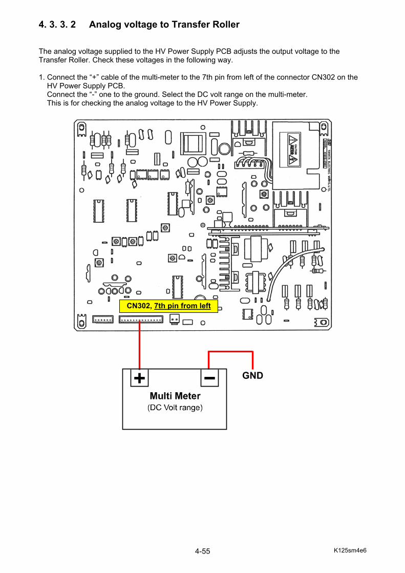
K125sm4e6 4-55
4. 3. 3. 2 Analog voltage to Transfer Roller The analog voltage supplied to the HV Power Supply PCB adjusts the output voltage to the Transfer Roller. Check these voltages in the following way. 1. Connect the “+” cable of the multi-meter to the 7th pin from left of the connector CN302 on the
HV Power Supply PCB. Connect the “-” one to the ground. Select the DC volt range on the multi-meter. This is for checking the analog voltage to the HV Power Supply.
GND
CN302, 7th pin from left

K125sm4e6 4-56
2. Run the service software. - Press [service mode] on the home screen. - Select [setting] on “service mode” sub window. - Select [high voltage]. - Find item No.2468 to 2503 (transfer roller voltage offset).
3. There are many Transfer Roller Voltage Offset settings being conditioned by such factors as process color (#1=K, #2=C, #3=M & #4=Y), print speed (60mm/s, 100mm/s & 120mm/s) and print size (large, middle and small). At first be sure that these settings are correctly set to particular values (200 for heavy and 300 for color and monochrome). See the following Reference to know which media width belongs to which print size.
mode Print size Particular setting valueheavy (60mm/s) large 200
middle 200 small 200
color (100mm/s) large 300 middle 300 small 300
monochrome(120mm/s) large 300 middle 300 small 300
Reference
Media width Print size Media width Print size 900.0mm large 610.0mm middle 891.0mm large A1(594.0mm) middle 880.0mm large B2(515.0mm) middle A0(841.0mm) large 440.0mm small B1(728.0mm) middle A2(420.0mm) small B1(707.0mm) middle B3(364.0mm) small 700.0mm middle A3(297.0mm) small 620.0mm middle
Media width Print size 36“ (914.4mm) large 34” (863.6mm) large 30” (762.0mm) middle 24” (609.6mm) middle 22” (558.8mm) middle 18” (457.2mm) small 17” (431.8mm) small 15” (381.0mm) small 12” (304.8mm) small 11” (279.4mm) small

K125sm4e6 4-57
4. Go back to the home screen without cancelling the service mode. Press [test print]. 5. In test print page, set [mode] to any of monochrome, color and heavy according to your target for measurement. Please note that the printer speed differs among 3 selectable [mode] settings, and the analog voltage output to Transfer Roller differs respectively. Monochrome : 120mm/sec Color : 100mm/sec Heavy : 60mm/sec If you will measure the analog voltage that is provided to the Transfer Roller when the speed is
100mm/sec (color mode), for example, set [mode] to “color”.
NOTE
Status is not in service mode if “service mode” is not indicated here. In this case please re-enter the service mode before pressing [service mode].
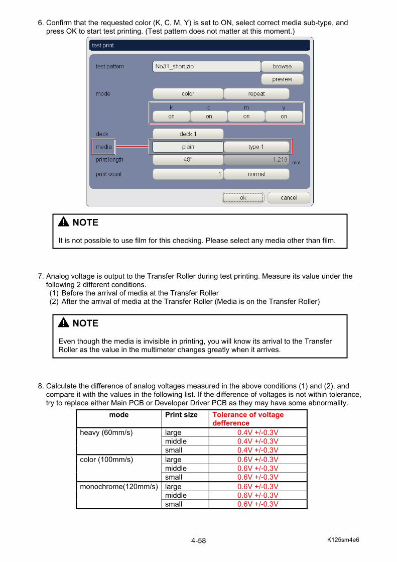
K125sm4e6 4-58
6. Confirm that the requested color (K, C, M, Y) is set to ON, select correct media sub-type, and press OK to start test printing. (Test pattern does not matter at this moment.) 7. Analog voltage is output to the Transfer Roller during test printing. Measure its value under the
following 2 different conditions. (1) Before the arrival of media at the Transfer Roller (2) After the arrival of media at the Transfer Roller (Media is on the Transfer Roller)
8. Calculate the difference of analog voltages measured in the above conditions (1) and (2), and
compare it with the values in the following list. If the difference of voltages is not within tolerance, try to replace either Main PCB or Developer Driver PCB as they may have some abnormality.
NOTE Even though the media is invisible in printing, you will know its arrival to the Transfer Roller as the value in the multimeter changes greatly when it arrives.
NOTE It is not possible to use film for this checking. Please select any media other than film.
mode Print size Tolerance of voltage defference
heavy (60mm/s) large 0.4V +/-0.3V middle 0.4V +/-0.3V small 0.4V +/-0.3V
color (100mm/s) large 0.6V +/-0.3V middle 0.6V +/-0.3V small 0.6V +/-0.3V
monochrome(120mm/s) large 0.6V +/-0.3V middle 0.6V +/-0.3V small 0.6V +/-0.3V
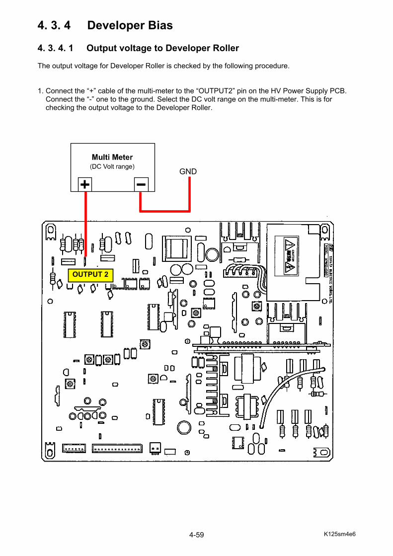
K125sm4e6 4-59
4. 3. 4 Developer Bias 4. 3. 4. 1 Output voltage to Developer Roller The output voltage for Developer Roller is checked by the following procedure. 1. Connect the “+” cable of the multi-meter to the “OUTPUT2” pin on the HV Power Supply PCB. Connect the “-” one to the ground. Select the DC volt range on the multi-meter. This is for checking the output voltage to the Developer Roller.
OUTPUT 2
GND
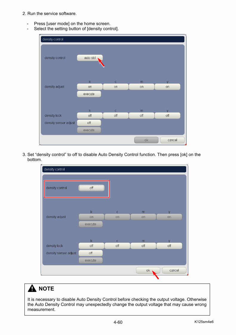
K125sm4e6 4-60
2. Run the service software. - Press [user mode] on the home screen. - Select the setting button of [density control].
3. Set “density control” to off to disable Auto Density Control function. Then press [ok] on the bottom.
NOTE It is necessary to disable Auto Density Control before checking the output voltage. Otherwise the Auto Density Control may unexpectedly change the output voltage that may cause wrong measurement.
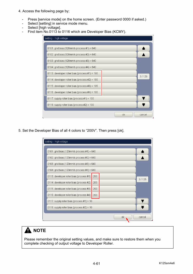
K125sm4e6 4-61
4. Access the following page by;
- Press [service mode] on the home screen. (Enter password 0000 if asked.) - Select [setting] in service mode menu. - Select [high voltage]. - Find item No.0113 to 0116 which are Developer Bias (KCMY).
5. Set the Developer Bias of all 4 colors to “200V”. Then press [ok].
NOTE Please remember the original setting values, and make sure to restore them when you complete checking of output voltage to Developer Roller.

K125sm4e6 4-62
6. Go back to the home screen without cancelling the service mode. Press [test print]. 7. Select any pattern. and set [mode] to “color”. After confirming your target color is set to “on”, press [ok] to take a test printing.
NOTE
Status is not in service mode if “service mode” is not indicated here. In this case please re-enter the service mode before pressing [service mode].
NOTE Please set [mode] to “color” (speed=100mm/sec) for correct measurement. Setting it to “heavy” (60mm/sec) or “monochrome” (120mm/sec) is not good for correct measurement.

K125sm4e6 4-63
7. During test printing measure the high voltage supplied to Developer Roller. If the Developer Bias (No.0113 to 0116) is currently set to 200V as done at the previous step 5, the output voltage normally satisfies -200 +/-5V.
8. When you have finished checking of output voltage, make sure to set Developer Bias (No.0113 to 0116) back to their original values.
NOTE If the measured voltage does not satisfy the above voltage requirement (-200 +/-5V), the corresponding analog voltage output to the HV Power Supply PCB may be abnormal. Follow the instruction on [4.3.5.2 Analog Voltage to Developer Roller] to check the analog outputs. If the analog voltage is correct, the HV Power Supply PCB may have some abnormality. Try to replace it with a new one for confirmation.
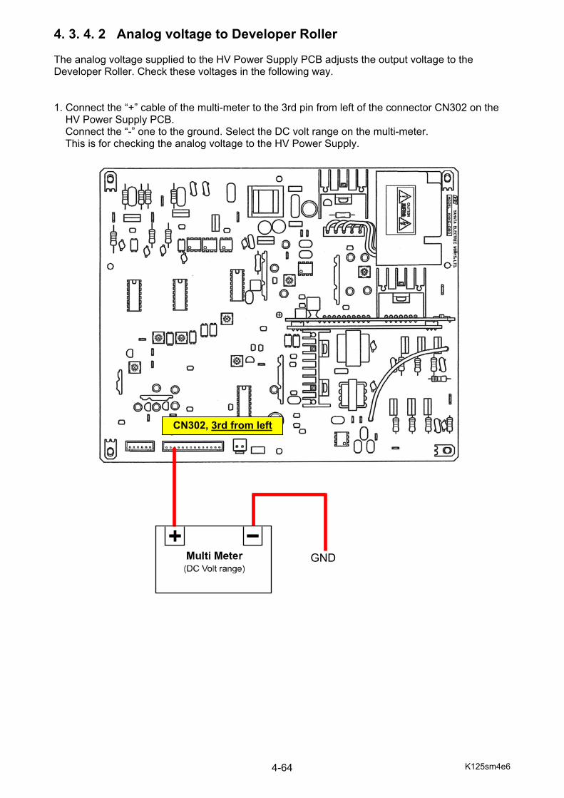
K125sm4e6 4-64
4. 3. 4. 2 Analog voltage to Developer Roller The analog voltage supplied to the HV Power Supply PCB adjusts the output voltage to the Developer Roller. Check these voltages in the following way. 1. Connect the “+” cable of the multi-meter to the 3rd pin from left of the connector CN302 on the
HV Power Supply PCB. Connect the “-” one to the ground. Select the DC volt range on the multi-meter. This is for checking the analog voltage to the HV Power Supply.
GND
CN302, 3rd from left

K125sm4e6 4-65
2. Run the service software. - Press [user mode] on the home screen. - Select the setting button of [density control].
3. Set “density control” to off to disable Auto Density Control function. Then press [ok] on the bottom.
NOTE It is necessary to disable Auto Density Control before checking the output voltage. Otherwise the Auto Density Control may unexpectedly change the output voltage that may cause wrong measurement.

K125sm4e6 4-66
4. Access the following page by;
- Press [service mode] on the home screen. - Select [setting] in service mode menu. - Select [high voltage]. - Find item No.0113 to 0116 which are Developer Bias (KCMY).
5. Set the Developer Bias of all 4 colors to “200V”. Then press [ok].
NOTE Remember the current Developer Bias values as they must be entered again after checking.
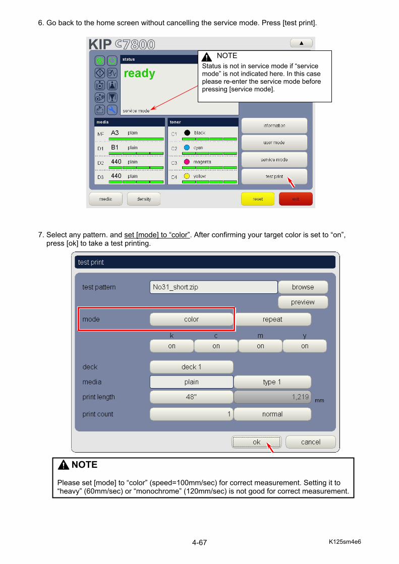
K125sm4e6 4-67
6. Go back to the home screen without cancelling the service mode. Press [test print]. 7. Select any pattern. and set [mode] to “color”. After confirming your target color is set to “on”, press [ok] to take a test printing.
NOTE
Status is not in service mode if “service mode” is not indicated here. In this case please re-enter the service mode before pressing [service mode].
NOTE Please set [mode] to “color” (speed=100mm/sec) for correct measurement. Setting it to “heavy” (60mm/sec) or “monochrome” (120mm/sec) is not good for correct measurement.
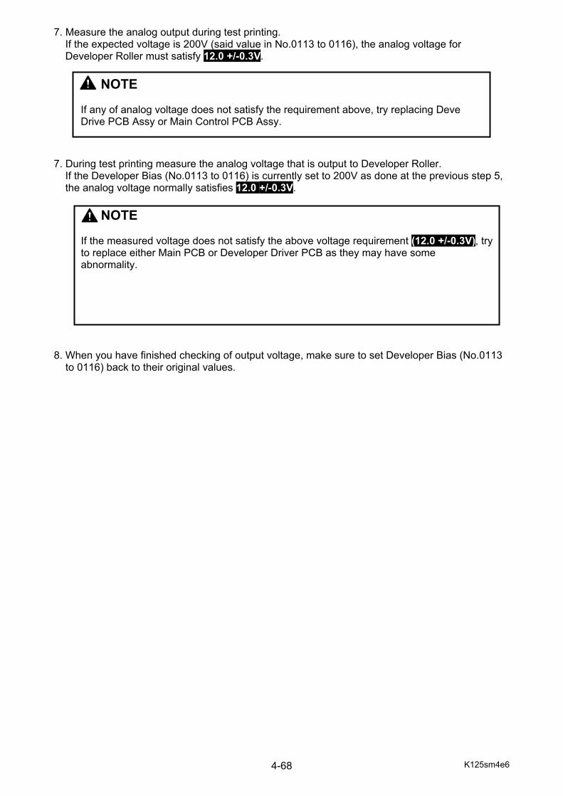
K125sm4e6 4-68
7. Measure the analog output during test printing. If the expected voltage is 200V (said value in No.0113 to 0116), the analog voltage for Developer Roller must satisfy 12.0 +/-0.3V.
7. During test printing measure the analog voltage that is output to Developer Roller.
If the Developer Bias (No.0113 to 0116) is currently set to 200V as done at the previous step 5, the analog voltage normally satisfies 12.0 +/-0.3V.
8. When you have finished checking of output voltage, make sure to set Developer Bias (No.0113 to 0116) back to their original values.
NOTE If any of analog voltage does not satisfy the requirement above, try replacing Deve Drive PCB Assy or Main Control PCB Assy.
NOTE If the measured voltage does not satisfy the above voltage requirement (12.0 +/-0.3V), try to replace either Main PCB or Developer Driver PCB as they may have some abnormality.
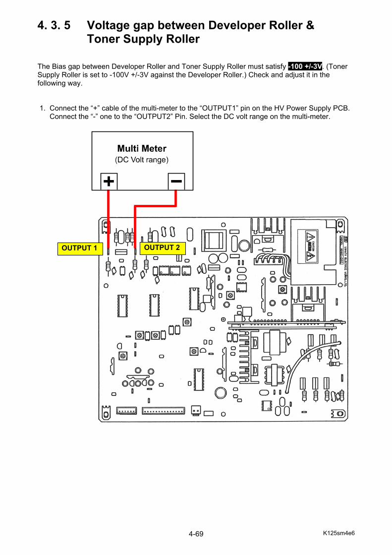
K125sm4e6 4-69
4. 3. 5 Voltage gap between Developer Roller & Toner Supply Roller The Bias gap between Developer Roller and Toner Supply Roller must satisfy -100 +/-3V. (Toner Supply Roller is set to -100V +/-3V against the Developer Roller.) Check and adjust it in the following way. 1. Connect the “+” cable of the multi-meter to the “OUTPUT1” pin on the HV Power Supply PCB. Connect the “-” one to the “OUTPUT2” Pin. Select the DC volt range on the multi-meter.
OUTPUT 1 OUTPUT 2
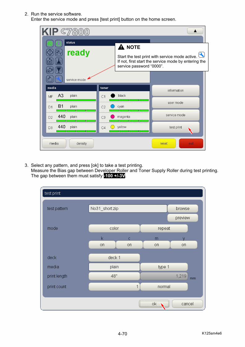
K125sm4e6 4-70
2. Run the service software. Enter the service mode and press [test print] button on the home screen. 3. Select any pattern, and press [ok] to take a test printing. Measure the Bias gap between Developer Roller and Toner Supply Roller during test printing. The gap between them must satisfy -100 +/-3V.
NOTE
Start the test print with service mode active. If not, first start the service mode by entering the service password “0000”.
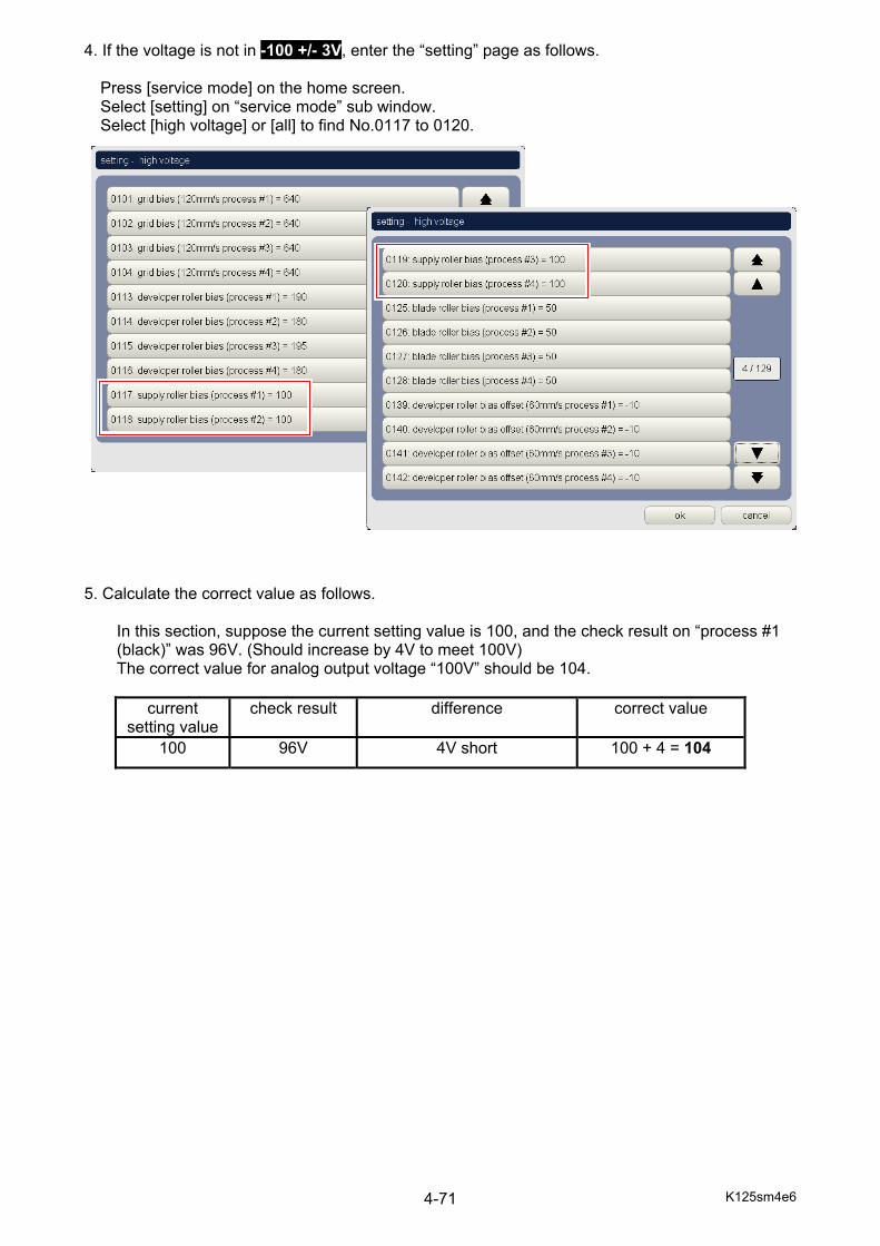
K125sm4e6 4-71
4. If the voltage is not in -100 +/- 3V, enter the “setting” page as follows.
Press [service mode] on the home screen. Select [setting] on “service mode” sub window. Select [high voltage] or [all] to find No.0117 to 0120.
5. Calculate the correct value as follows.
In this section, suppose the current setting value is 100, and the check result on “process #1 (black)” was 96V. (Should increase by 4V to meet 100V) The correct value for analog output voltage “100V” should be 104.
current setting value
check result difference correct value
100 96V 4V short 100 + 4 = 104
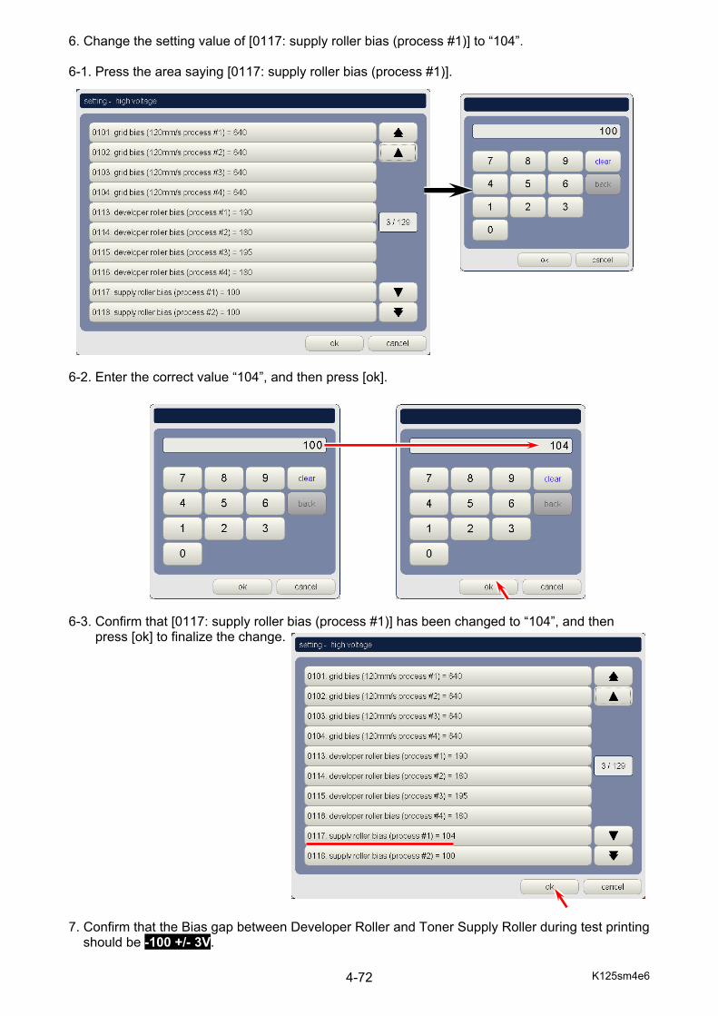
K125sm4e6 4-72
6. Change the setting value of [0117: supply roller bias (process #1)] to “104”. 6-1. Press the area saying [0117: supply roller bias (process #1)]. 6-2. Enter the correct value “104”, and then press [ok]. 6-3. Confirm that [0117: supply roller bias (process #1)] has been changed to “104”, and then
press [ok] to finalize the change. 7. Confirm that the Bias gap between Developer Roller and Toner Supply Roller during test printing
should be -100 +/- 3V.
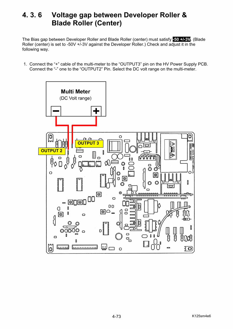
K125sm4e6 4-73
4. 3. 6 Voltage gap between Developer Roller & Blade Roller (Center) The Bias gap between Developer Roller and Blade Roller (center) must satisfy -50 +/-3V. (Blade Roller (center) is set to -50V +/-3V against the Developer Roller.) Check and adjust it in the following way. 1. Connect the “+” cable of the multi-meter to the “OUTPUT3” pin on the HV Power Supply PCB. Connect the “-” one to the “OUTPUT2” Pin. Select the DC volt range on the multi-meter.
OUTPUT 3
OUTPUT 2
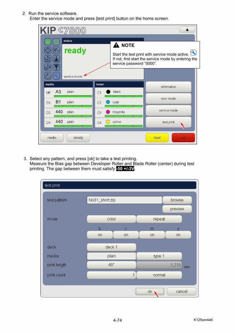
K125sm4e6 4-74
2. Run the service software. Enter the service mode and press [test print] button on the home screen. 3. Select any pattern, and press [ok] to take a test printing. Measure the Bias gap between Developer Roller and Blade Roller (center) during test printing. The gap between them must satisfy -50 +/-3V.
NOTE
Start the test print with service mode active. If not, first start the service mode by entering the service password “0000”.
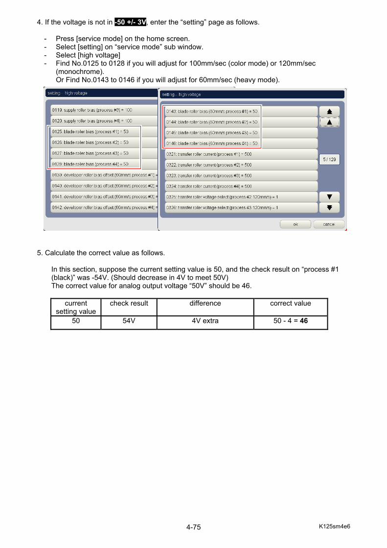
K125sm4e6 4-75
4. If the voltage is not in -50 +/- 3V, enter the “setting” page as follows.
- Press [service mode] on the home screen. - Select [setting] on “service mode” sub window. - Select [high voltage] - Find No.0125 to 0128 if you will adjust for 100mm/sec (color mode) or 120mm/sec
(monochrome). Or Find No.0143 to 0146 if you will adjust for 60mm/sec (heavy mode).
5. Calculate the correct value as follows.
In this section, suppose the current setting value is 50, and the check result on “process #1 (black)” was -54V. (Should decrease in 4V to meet 50V) The correct value for analog output voltage “50V” should be 46.
current setting value
check result difference correct value
50 54V 4V extra 50 - 4 = 46
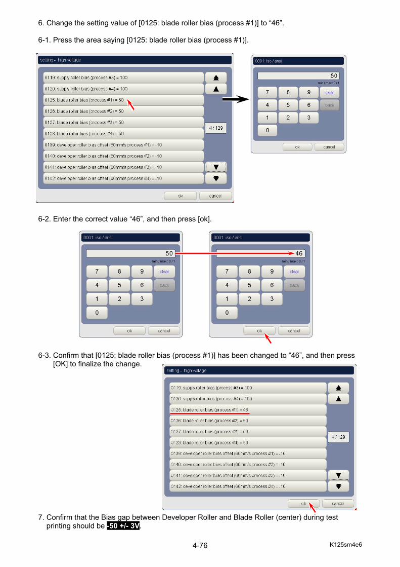
K125sm4e6 4-76
6. Change the setting value of [0125: blade roller bias (process #1)] to “46”. 6-1. Press the area saying [0125: blade roller bias (process #1)]. 6-2. Enter the correct value “46”, and then press [ok]. 6-3. Confirm that [0125: blade roller bias (process #1)] has been changed to “46”, and then press
[OK] to finalize the change. 7. Confirm that the Bias gap between Developer Roller and Blade Roller (center) during test
printing should be -50 +/- 3V.

K125sm4e6 4-77
4. 3. 7 Voltage gap between Developer Roller & Blade Roller (Both sides) The Bias gap between Developer Roller and Blade Roller (both sides) must satisfy +300 +/-3V. (Blade Roller (both sides) is set to +300V +/-3V against the Developer Roller.) Check and adjust it in the following way. 1. Connect the “+” cable of the multi-meter to the “OUTPUT4” pin on the HV Power Supply PCB. Connect the “-” one to the “OUTPUT2” Pin. Select the DC volt range on the multi-meter.
OUTPUT 4OUTPUT 2

K125sm4e6 4-78
2. Run the service software. Enter the service mode and press [test print] button on the home screen. 3. Select any pattern, and press [ok] to take a test printing. Measure the Bias gap between Developer Roller and Blade Roller (both sides) during test printing. The gap between them must satisfy +300 +/-3V.
NOTE
Start the test print with service mode active. If not, first start the service mode by entering the service password “0000”.

K125sm4e6 4-79
4. If the gap does not satisfy +300 +/-3V, adjust it rotating the “OUT PUT 4 VR” with a screwdriver.
OUTPUT 4 VR
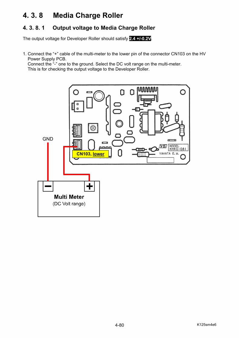
K125sm4e6 4-80
4. 3. 8 Media Charge Roller 4. 3. 8. 1 Output voltage to Media Charge Roller The output voltage for Developer Roller should satisfy 2.4 +/-0.2V. 1. Connect the “+” cable of the multi-meter to the lower pin of the connector CN103 on the HV
Power Supply PCB. Connect the “-” one to the ground. Select the DC volt range on the multi-meter. This is for checking the output voltage to the Developer Roller.
GND
CN103, lower
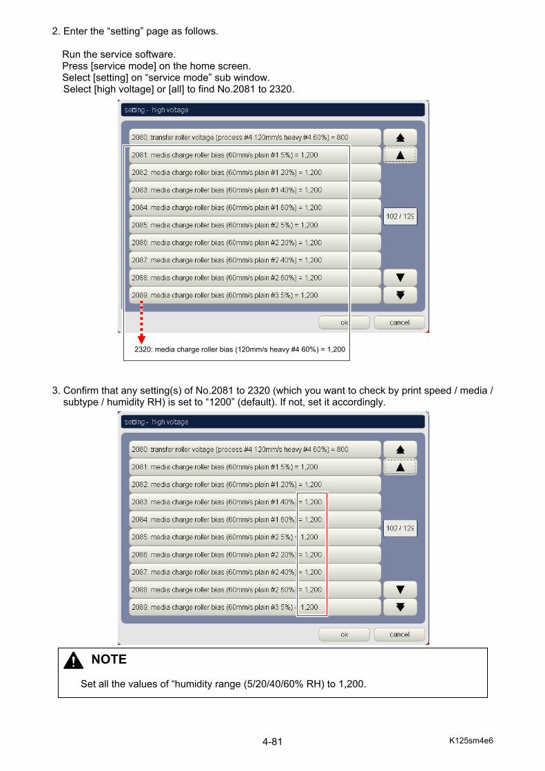
K125sm4e6 4-81
2. Enter the “setting” page as follows. Run the service software. Press [service mode] on the home screen. Select [setting] on “service mode” sub window. Select [high voltage] or [all] to find No.2081 to 2320.
3. Confirm that any setting(s) of No.2081 to 2320 (which you want to check by print speed / media /
subtype / humidity RH) is set to “1200” (default). If not, set it accordingly.
NOTE
Set all the values of “humidity range (5/20/40/60% RH) to 1,200.
2320: media charge roller bias (120mm/s heavy #4 60%) = 1,200
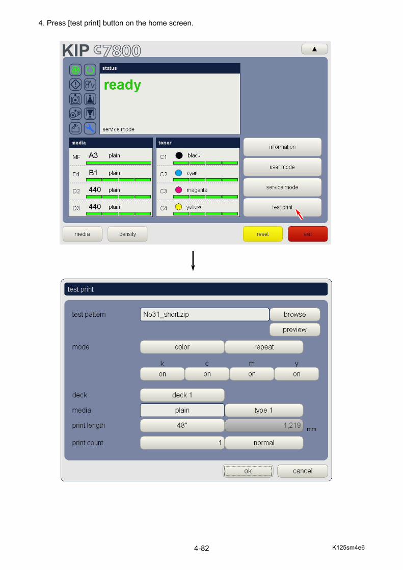
K125sm4e6 4-82
4. Press [test print] button on the home screen.

K125sm4e6 4-83
5. Select any pattern, and press [ok] to take a test printing. Measure the high voltage supplied to the Media Charge Roller during test printing. The output voltage must satisfy 2.4 +/-0.2V.
NOTE If the voltage does not satisfy 2.4 +/-0.2V, the corresponding analog output to the HV Power Supply PCB has an abnormality. Follow the instruction on [4.3.9.2 Analog Voltage to Media Charge Roller] to confirm the analog outputs. When the confirmation leads there is no problem on the analog output, the abnormality comes from the HV Power Supply PCB. Replace it with a new one.
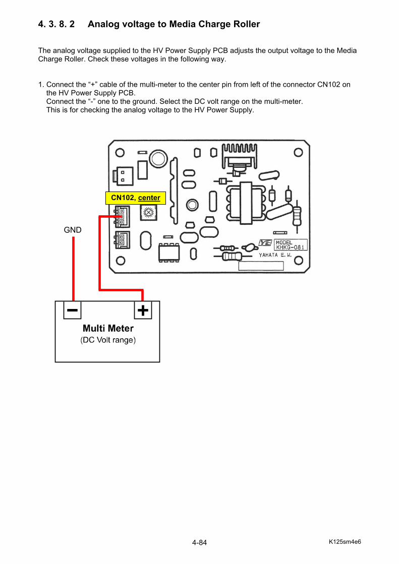
K125sm4e6 4-84
4. 3. 8. 2 Analog voltage to Media Charge Roller The analog voltage supplied to the HV Power Supply PCB adjusts the output voltage to the Media Charge Roller. Check these voltages in the following way. 1. Connect the “+” cable of the multi-meter to the center pin from left of the connector CN102 on
the HV Power Supply PCB. Connect the “-” one to the ground. Select the DC volt range on the multi-meter. This is for checking the analog voltage to the HV Power Supply.
CN102, center
GND
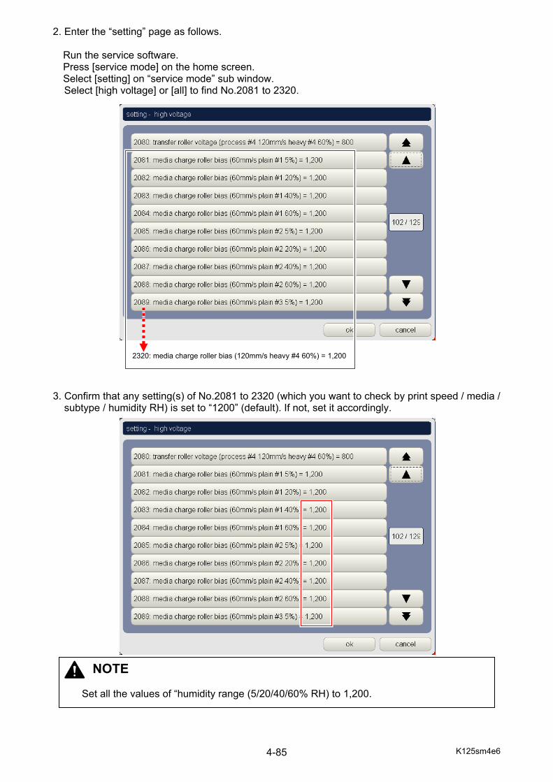
K125sm4e6 4-85
2. Enter the “setting” page as follows. Run the service software. Press [service mode] on the home screen. Select [setting] on “service mode” sub window. Select [high voltage] or [all] to find No.2081 to 2320.
3. Confirm that any setting(s) of No.2081 to 2320 (which you want to check by print speed / media /
subtype / humidity RH) is set to “1200” (default). If not, set it accordingly.
NOTE
Set all the values of “humidity range (5/20/40/60% RH) to 1,200.
2320: media charge roller bias (120mm/s heavy #4 60%) = 1,200

K125sm4e6 4-86
4. Press [test print] button on the home screen.

K125sm4e6 4-87
5. Measure the analog output during test printing. If the value in No.2081 to 2320, the analog voltage for Media Charge Roller must satisfy 13.0 +/-0.2V.
NOTE If any of analog voltage does not satisfy the requirement above, try replacing Deve Drive PCB Assy or Main Control PCB Assy.

K125sm5e1
Chapter 5
Mechanical
Page 5. 1 Outer Cover 5- 1
5. 1. 1 Removing Right Side Cover 5- 1 5. 1. 2 Removing Left Side Door / Frame 5- 2 5. 1. 3 Removing Top Cover 5- 5
5. 2 Process Unit 5- 9
5. 2. 1 Drawing Process Unit 5- 9 5. 2. 2 Removing Drum and Cleaner Unit 5- 11 5. 2. 3 Removing Developer Unit 5- 18 5. 2. 4 Removing 1st Charging Unit 5- 23
5. 3 Drum & Drum Cleaner Unit 5- 26
5. 3. 1 Recommended Periodic Replacement 5- 26
NOTE When you take several mechanical operations as instructed in this chapter, you will often need to open the Rear Cover and draw out the Process Unit. Please make sure to satisfy the following requirements in that case. (1) Make sure to open the Rear Cover (with Belt Unit) first and then draw out the Process
Unit next. Drum or Belt may possibly be damaged if you draw out the Process Unit without opening the Rear Cover.
(2) Drum is exposed to the light when you open the Rear Cover or draw out the Process
Unit, which may possibly damage the Drum. Drum must NEVER been exposed to the direct sunlight! Even if the light is not the direct sunlight but the room illumination, it is not good to expose the Drum to such light for long time. Please minimize the time of exposure, or preferably put the Drum in an exclusive box to avoid any light.
Rear door Drum Drums Process unit

K125sm5e1
5. 4 Developer Unit 5- 49 5. 4. 1 Recommended Periodic Replacement 5- 49
5. 5 1st Charging Unit 5- 66
5. 5. 1 Recommended Periodic Replacement 5- 66 5. 6 Fuser Unit 5- 72
5. 6. 1 Recommended Periodic Replacement 5- 72 5. 6. 2 Removing Fuser Unit 5- 93 5. 6. 3 Replacing Web Cleaner 5-110
5. 7 Filter 5-120
5. 7. 1 Replacing Filter 5-120 5. 8 Belt Unit 5-122
5. 8. 1 Replacing BC Blade 5-122 5. 8. 2 Replacing Belt 5-131
5. 9 Roll Deck 5-134
5. 9. 1 Removing Roll Deck 5-134 5. 10 Inner Feeder Unit 5-136
5. 10. 1 Removing Inner Feeder Unit 5-136 5. 11 Cutter Unit 5-140
5. 11. 1 Removing Cutter Unit 5-140
5. 12 LED Head 5-143 5. 12. 1 Removing LED Head 5-143 5. 12. 2 Replacing LED Head Lock mechanism 5-161
5. 14 Auto Stacker (option) 5-9
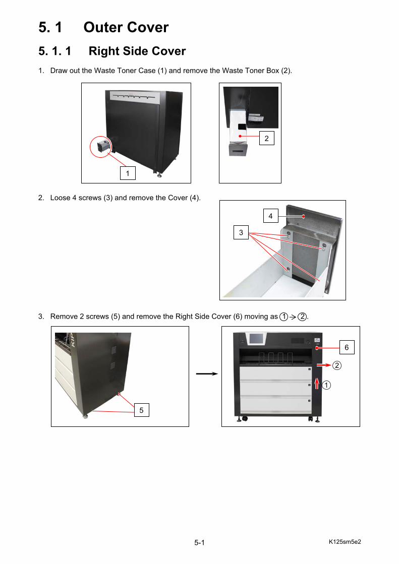
K125sm5e2 5-1
5. 1 Outer Cover
5. 1. 1 Right Side Cover 1. Draw out the Waste Toner Case (1) and remove the Waste Toner Box (2). 2. Loose 4 screws (3) and remove the Cover (4). 3. Remove 2 screws (5) and remove the Right Side Cover (6) moving as 1 2 .
5
4
3
1
2
6

K125sm5e2 5-2
5. 1. 2 Left Side Door / Frame 1. Open the Left Side Door (1) 2. Remove the screw (2), and remove the Door Stopper (3). 3. Remove the screw (4), and remove the Door Bracket (5).
1
23
5 4
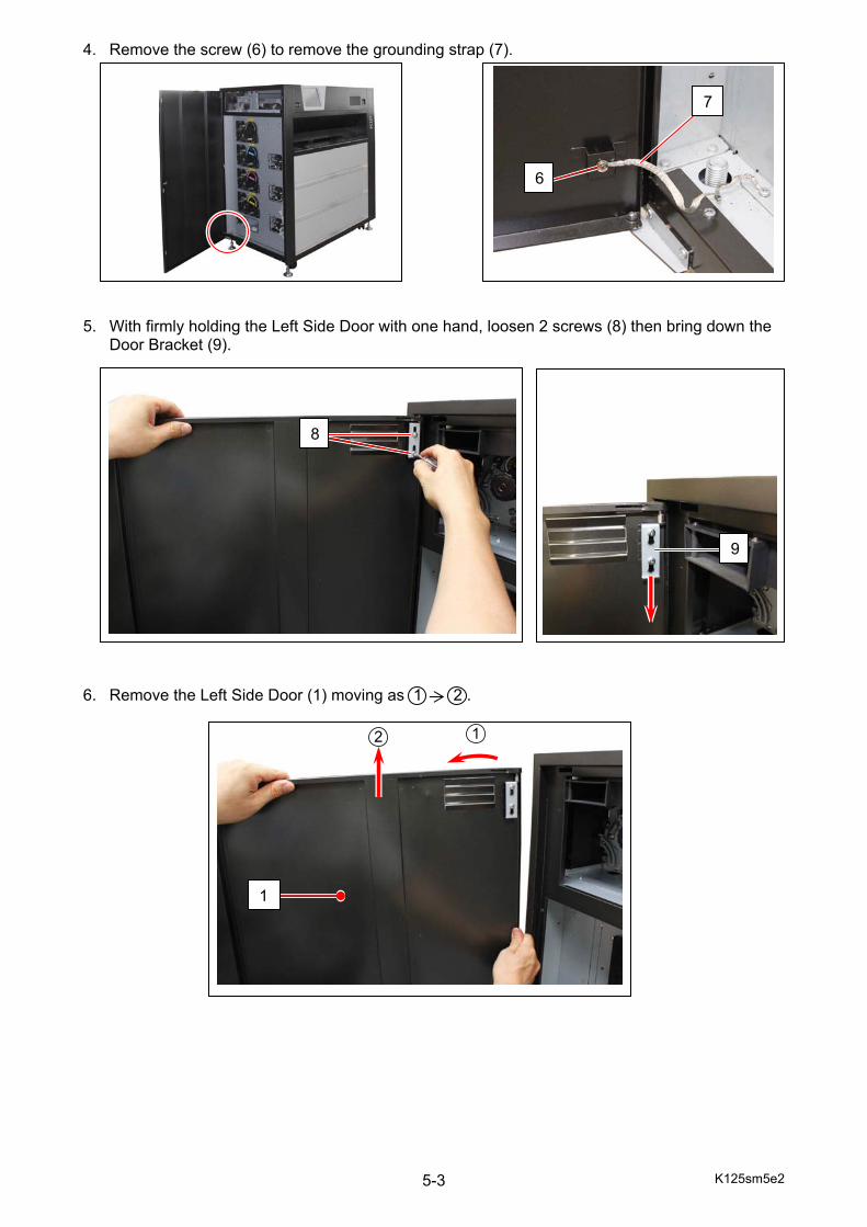
K125sm5e2 5-3
4. Remove the screw (6) to remove the grounding strap (7). 5. With firmly holding the Left Side Door with one hand, loosen 2 screws (8) then bring down the
Door Bracket (9). 6. Remove the Left Side Door (1) moving as 1 2 .
8
6
7
1
9
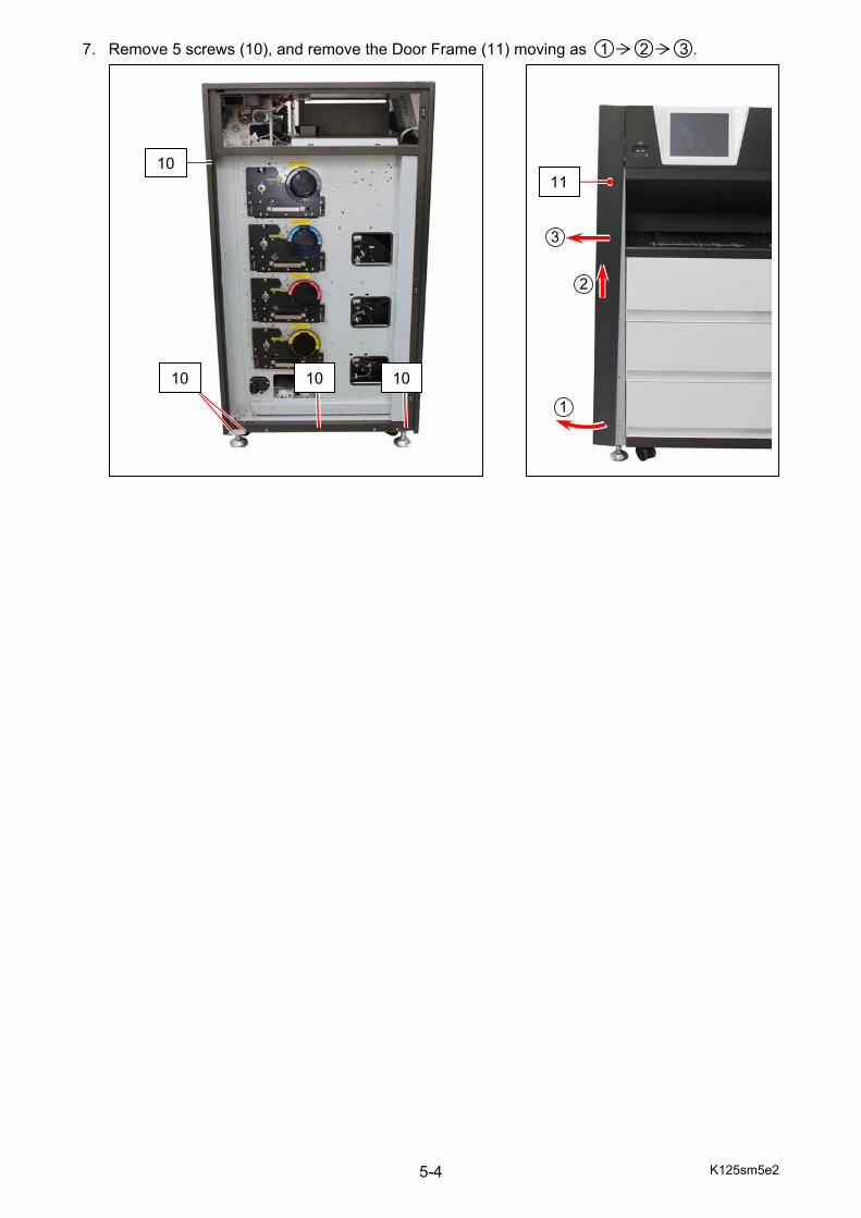
K125sm5e2 5-4
7. Remove 5 screws (10), and remove the Door Frame (11) moving as 1 2 3 .
10
10 10 10
11
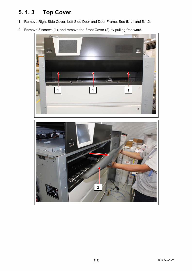
K125sm5e2 5-5
5. 1. 3 Top Cover 1. Remove Right Side Cover, Left Side Door and Door Frame. See 5.1.1 and 5.1.2. 2. Remove 3 screws (1), and remove the Front Cover (2) by pulling frontward.
111
2
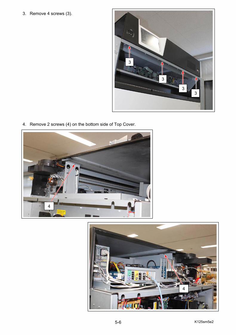
K125sm5e2 5-6
3. Remove 4 screws (3). 4. Remove 2 screws (4) on the bottom side of Top Cover.
3
4
4
3
3
3
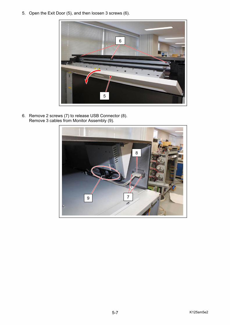
K125sm5e2 5-7
5. Open the Exit Door (5), and then loosen 3 screws (6). 6. Remove 2 screws (7) to release USB Connector (8).
Remove 3 cables from Monitor Assembly (9).
5
6
7
8
9

K125sm5e2 5-8
7. Disconnect 4 harnesses (11) from the Power Switch. Disconnect 1 cable (12) from the Indicator PCB.
8. Lift up Top Cover.
Reference
Harness Connection:
In front (machine right)
Back (machine left)
Upper SW1-3 (white) SW1-4 (white) Lower SW1-1 (black) SW1-2 (black)
10
11
NOTE Carry Top Cover by 2 or more persons.
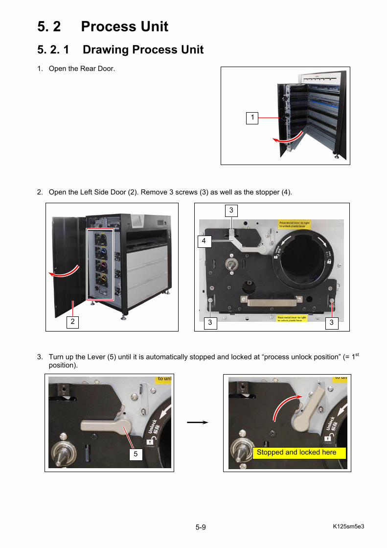
K125sm5e3 5-9
5. 2 Process Unit
5. 2. 1 Drawing Process Unit 1. Open the Rear Door. 2. Open the Left Side Door (2). Remove 3 screws (3) as well as the stopper (4). 3. Turn up the Lever (5) until it is automatically stopped and locked at “process unlock position” (= 1st
position).
1
3 3
3
4
5
2
Stopped and locked here
K125sm5e3 5-10
4. Surely hold the handle (6) and draw out the Process Unit (7).
NOTE If Process Unit is tightly held so it is unable to draw it out, rotate the Drum shaft slightly counter-clockwise with the Jig to release then draw it out.
6
7
K125sm5e3 5-11
5. 2. 2 Removing Drum and Cleaner Unit 1. Open the Rear Door. 2. Open the Left Side Door (2). Remove 3 screws (3) as well as the stopper (4). 3. Turn up the Lever (5) until it is automatically stopped and locked at “process unlock position” (= 1st
position).
1
3 3
3
4
5
2
NOTE Prepare a Drum Box (Drum container). The Drum should be removed before removing Drum Cleaner.
Stopped and locked here

K125sm5e3 5-12
4. Surely hold the handle (6) and draw out the Process Unit (7).
NOTE If Process Unit is tightly held so it is unable to draw it out, rotate the Drum shaft slightly counter-clockwise with the Jig to release then draw it out.
6
7
K125sm5e3 5-13
5. With pushing Lever (8) to the arrow direction, insert the bolt (9: Reuse the attached as shipment accessory) to the hole. This unlocks the Drum as the bolt will prevent Lever from returning to the lock position.
8
9
If the bolt is lost, you can use a substitute such as a screwdriver.
Reference

K125sm5e3 5-14
6. With firmly holding both ends of Drum Cleaner Unit (10) and Drum (11) together by both hands, gently move them up in the direction of arrow until they are stopped by the metal stopper. 7. With firmly hold both flanges (12), bring up and remove the Drum from the Process unit.
12
12
NOTE Keep the Drum in the Drum Box. Do not expose it to the light so long time.
10
11
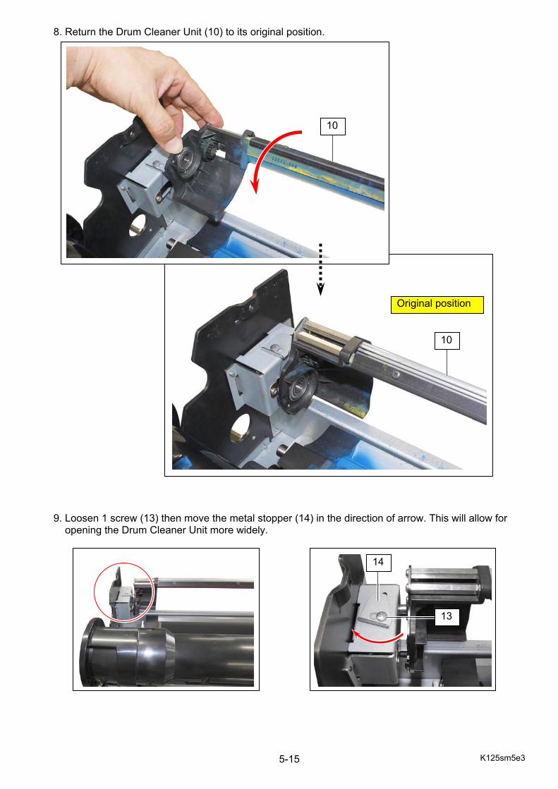
K125sm5e3 5-15
8. Return the Drum Cleaner Unit (10) to its original position. 9. Loosen 1 screw (13) then move the metal stopper (14) in the direction of arrow. This will allow for opening the Drum Cleaner Unit more widely.
14
13
Original position
10
10

K125sm5e3 5-16
10. Rotate the Drum Cleaner Unit in the direction of arrow, and find correct position that allows the key (15) on the unit to match the key hole (16) on the bracket.
16
15
16 15
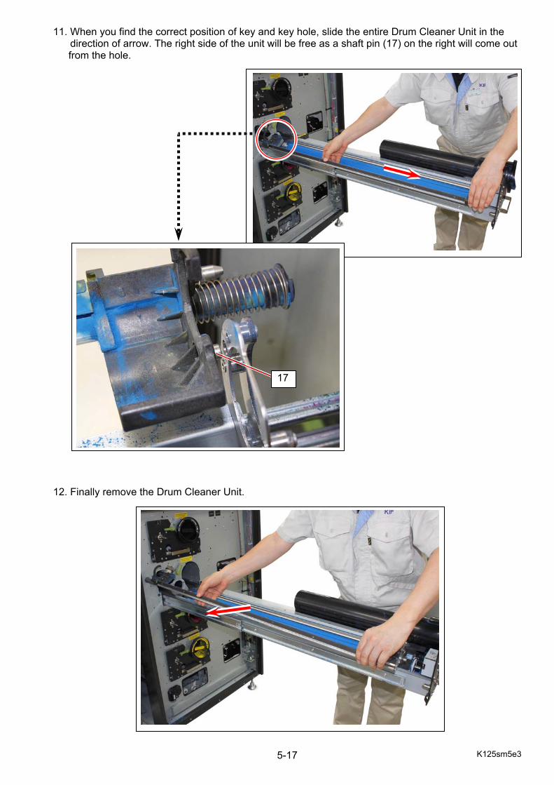
K125sm5e3 5-17
11. When you find the correct position of key and key hole, slide the entire Drum Cleaner Unit in the direction of arrow. The right side of the unit will be free as a shaft pin (17) on the right will come out
from the hole. 12. Finally remove the Drum Cleaner Unit.
17
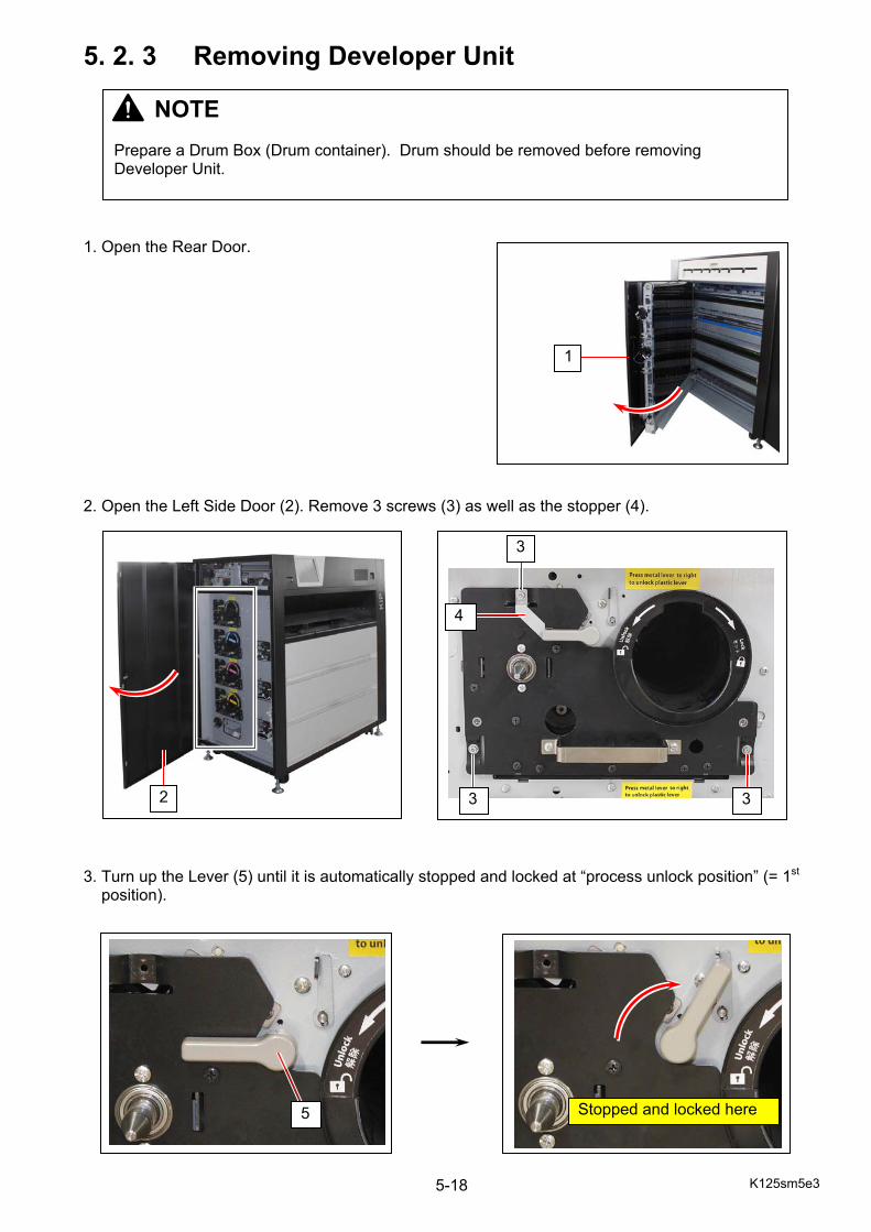
K125sm5e3 5-18
5. 2. 3 Removing Developer Unit 1. Open the Rear Door. 2. Open the Left Side Door (2). Remove 3 screws (3) as well as the stopper (4). 3. Turn up the Lever (5) until it is automatically stopped and locked at “process unlock position” (= 1st position).
1
3 3
3
4
5
2
Stopped and locked here
NOTE Prepare a Drum Box (Drum container). Drum should be removed before removing Developer Unit.

K125sm5e3 5-19
4. Surely hold the handle (6) and draw out the Process Unit (7).
NOTE If Process Unit is tightly held so it is unable to draw it out, rotate the Drum shaft slightly counter-clockwise with the Jig to release then draw it out.
6
7
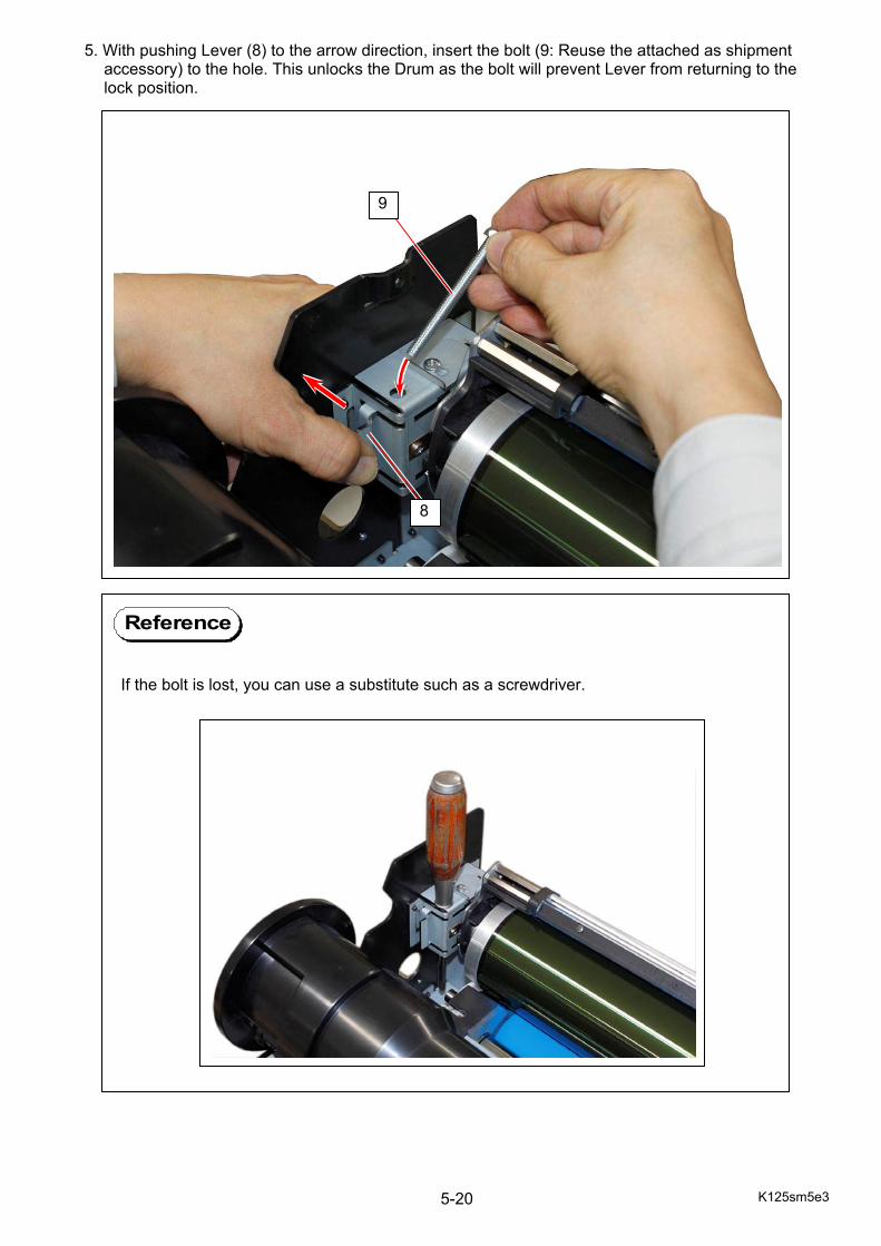
K125sm5e3 5-20
5. With pushing Lever (8) to the arrow direction, insert the bolt (9: Reuse the attached as shipment accessory) to the hole. This unlocks the Drum as the bolt will prevent Lever from returning to the lock position.
8
9
If the bolt is lost, you can use a substitute such as a screwdriver.
Reference
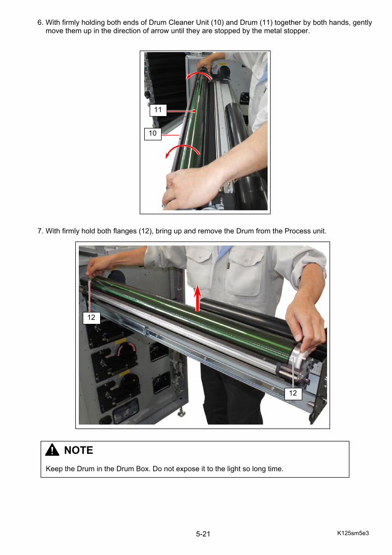
K125sm5e3 5-21
6. With firmly holding both ends of Drum Cleaner Unit (10) and Drum (11) together by both hands, gently move them up in the direction of arrow until they are stopped by the metal stopper. 7. With firmly hold both flanges (12), bring up and remove the Drum from the Process unit.
12
12
NOTE Keep the Drum in the Drum Box. Do not expose it to the light so long time.
11
10

K125sm5e3 5-22
8. With levelling the Developer Unit (13) as far as possible, simply bring it up and remove it from the Process Unit.
13
K125sm5e3 5-23
5. 2. 4 Removing 1st Charging Unit 1. Open the Rear Door. 2. Open the Left Side Door (2). Remove 3 screws (3) as well as the stopper (4). 3. Turn up the Lever (5) until it is automatically stopped and locked at “process unlock position” (= 1st position).
1
3 3
3
4
5
2
Stopped and locked here

K125sm5e3 5-24
4. Surely hold the handle (6) and draw out the Process Unit (7) full.
NOTE If Process Unit is tightly held so it is unable to draw it out, rotate the Drum shaft slightly counter-clockwise with the Jig to release then draw it out.
6
7
K125sm5e3 5-25
5. Holding HV Head (8), gently draw 1st Charging Unit (9).
8
9
NOTE Carefully remove 1st Charging Unit from the machine. Do not fall or hit 1st Charging Unit to Drum as they are located close each other.
K125sm5e4 5-26
5. 3 Drum & Drum Cleaner Unit
5. 3. 1 Recommended Periodic Replacement 1. Open the Rear Door (1). 2. Open the Left Side Door (2). Remove 3 screws (3) as well as the stopper (4).
NOTE The following parts are recommended for periodic replacement. This section describes how to replace all of them in one sequent operation.
Item Number Of article
Remarks
Drum 1 All of these parts are contained in “Drum Kit” Blade 1
Sheet 1 Seal 8 1 Seal 10 2 Seal 12 1 Seal 13 1 Seal 14 2 Seal 15 2 Sheet 4 1
1
3 3
3
4
2
K125sm5e4 5-27
3. Turn up the Lever (5) until it is automatically stopped and locked at “process unlock position” (= 1st position). 4. Surely hold the handle (6) and draw out the Process Unit (7).
5 Stopped and locked here
6
7
NOTE If Process Unit is tightly held so it is unable to draw it out, rotate the Drum shaft slightly counter-clockwise with the Jig to release then draw it out.
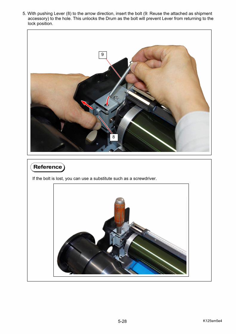
K125sm5e4 5-28
5. With pushing Lever (8) to the arrow direction, insert the bolt (9: Reuse the attached as shipment accessory) to the hole. This unlocks the Drum as the bolt will prevent Lever from returning to the lock position.
8
9
If the bolt is lost, you can use a substitute such as a screwdriver.
Reference
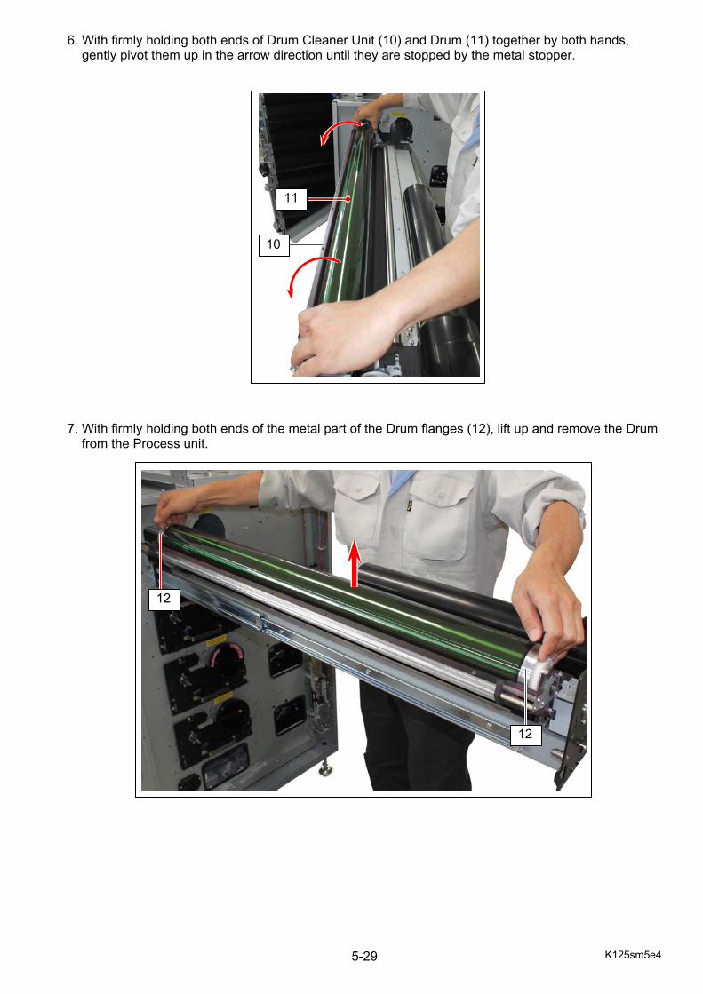
K125sm5e4 5-29
6. With firmly holding both ends of Drum Cleaner Unit (10) and Drum (11) together by both hands, gently pivot them up in the arrow direction until they are stopped by the metal stopper. 7. With firmly holding both ends of the metal part of the Drum flanges (12), lift up and remove the Drum
from the Process unit.
12
12
10
11

K125sm5e4 5-30
8. Return the Drum Cleaner Unit to its set position. 9. Loosen 1 screw (13) then slide the metal stopper (14) to the arrow direction. This will allow for opening the Drum Cleaner Unit more widely.
14
13
set position
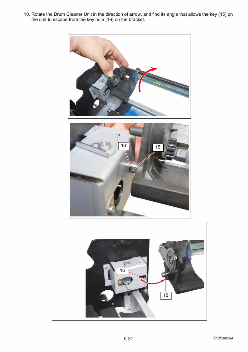
K125sm5e4 5-31
10. Rotate the Drum Cleaner Unit in the direction of arrow, and find its angle that allows the key (15) on the unit to escape from the key hole (16) on the bracket.
16
15
16 15
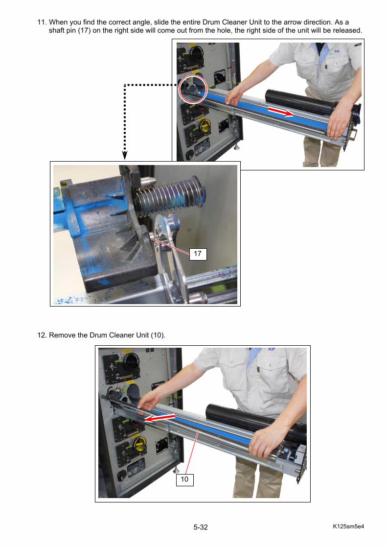
K125sm5e4 5-32
11. When you find the correct angle, slide the entire Drum Cleaner Unit to the arrow direction. As a shaft pin (17) on the right side will come out from the hole, the right side of the unit will be released.
12. Remove the Drum Cleaner Unit (10).
17
10
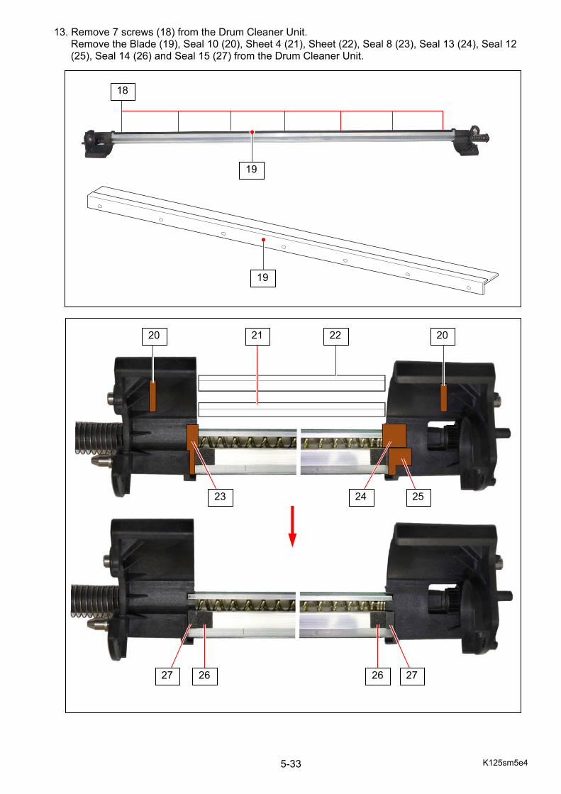
K125sm5e4 5-33
13. Remove 7 screws (18) from the Drum Cleaner Unit. Remove the Blade (19), Seal 10 (20), Sheet 4 (21), Sheet (22), Seal 8 (23), Seal 13 (24), Seal 12 (25), Seal 14 (26) and Seal 15 (27) from the Drum Cleaner Unit.
18
19
19
21 22 20 20
24
27 26 26 27
25 23
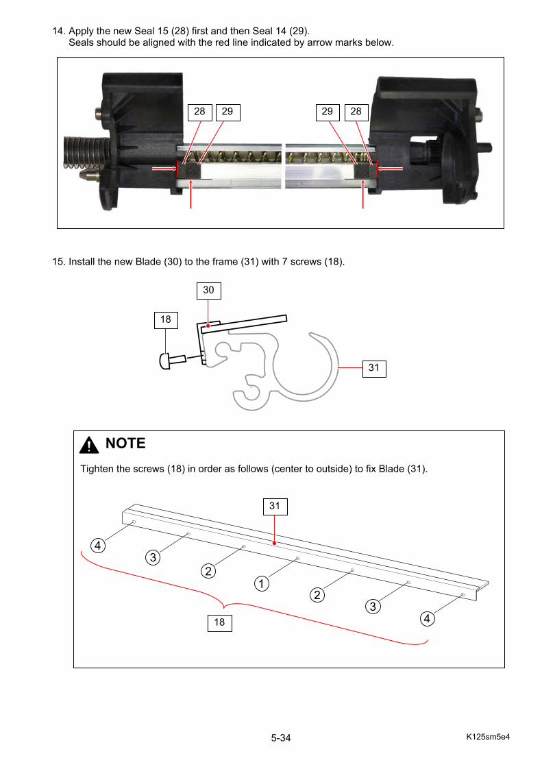
K125sm5e4 5-34
14. Apply the new Seal 15 (28) first and then Seal 14 (29). Seals should be aligned with the red line indicated by arrow marks below. 15. Install the new Blade (30) to the frame (31) with 7 screws (18).
28 29 29 28
NOTE Tighten the screws (18) in order as follows (center to outside) to fix Blade (31).
31
30
31
18
18
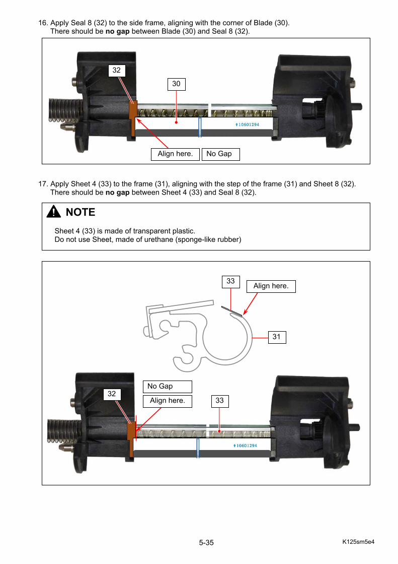
K125sm5e4 5-35
16. Apply Seal 8 (32) to the side frame, aligning with the corner of Blade (30). There should be no gap between Blade (30) and Seal 8 (32).
17. Apply Sheet 4 (33) to the frame (31), aligning with the step of the frame (31) and Sheet 8 (32).
There should be no gap between Sheet 4 (33) and Seal 8 (32).
32
Align here.
Align here.
No Gap
No Gap
30
Align here. 33
31
32
NOTE
Sheet 4 (33) is made of transparent plastic. Do not use Sheet, made of urethane (sponge-like rubber)
33
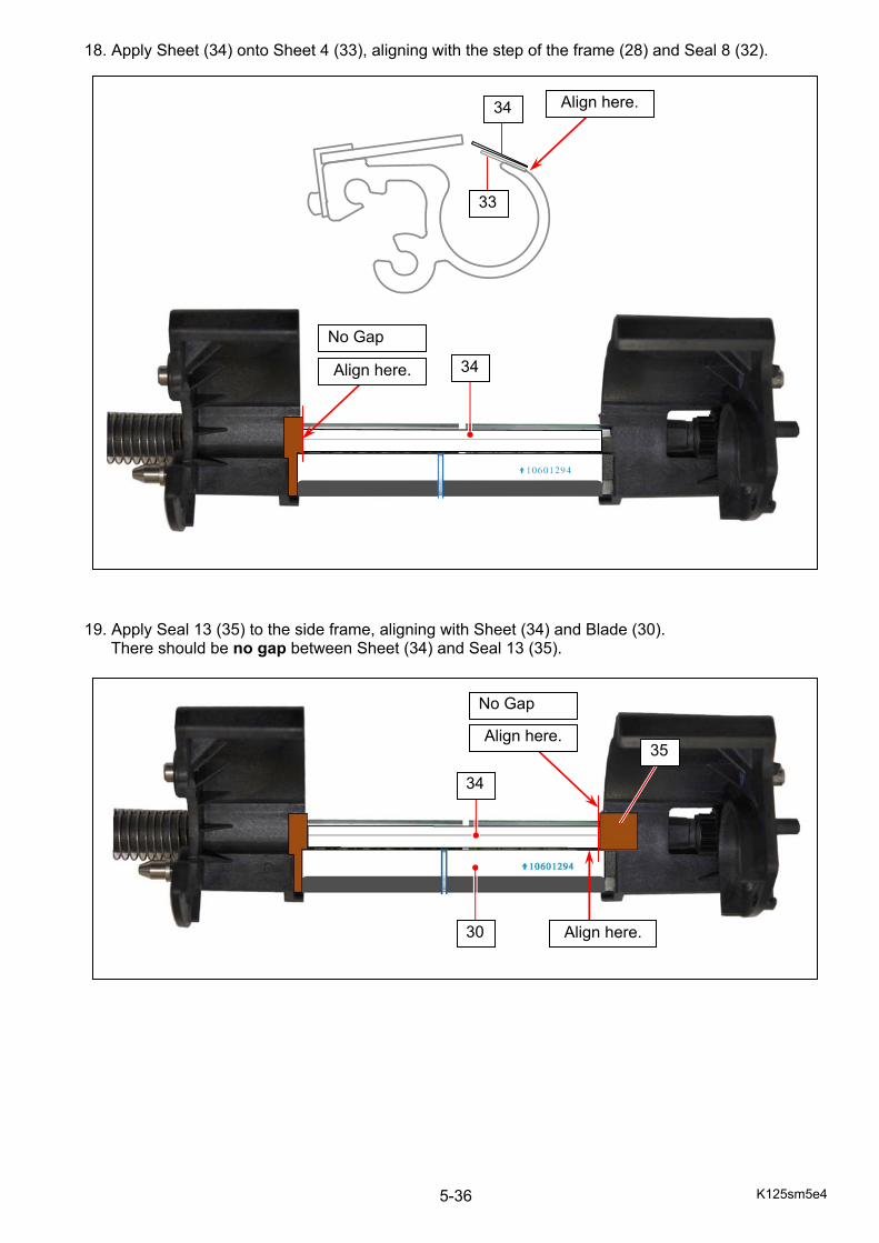
K125sm5e4 5-36
18. Apply Sheet (34) onto Sheet 4 (33), aligning with the step of the frame (28) and Seal 8 (32). 19. Apply Seal 13 (35) to the side frame, aligning with Sheet (34) and Blade (30).
There should be no gap between Sheet (34) and Seal 13 (35).
Align here.
No Gap
34
34
33
Align here.
Align here.
34
30
35 Align here.
No Gap
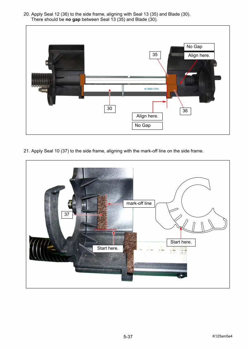
K125sm5e4 5-37
20. Apply Seal 12 (36) to the side frame, aligning with Seal 13 (35) and Blade (30). There should be no gap between Seal 13 (35) and Blade (30).
21. Apply Seal 10 (37) to the side frame, aligning with the mark-off line on the side frame.
35
36 30
No Gap
Align here.
Align here.
No Gap
mark-off line
37
Start here. Start here.
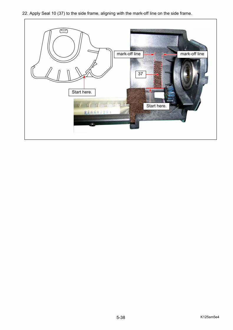
K125sm5e4 5-38
22. Apply Seal 10 (37) to the side frame, aligning with the mark-off line on the side frame.
Start here.
mark-off line mark-off line
37
Start here.
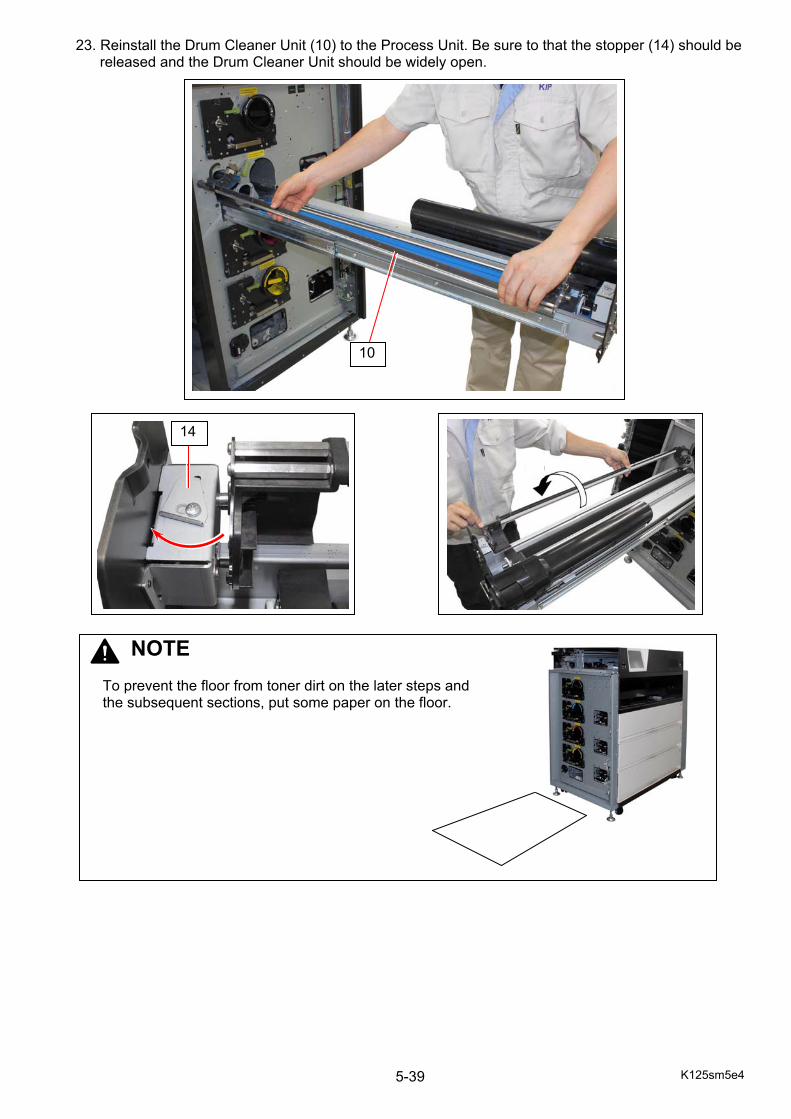
K125sm5e4 5-39
23. Reinstall the Drum Cleaner Unit (10) to the Process Unit. Be sure to that the stopper (14) should be released and the Drum Cleaner Unit should be widely open.
10
14
NOTE
To prevent the floor from toner dirt on the later steps and the subsequent sections, put some paper on the floor.
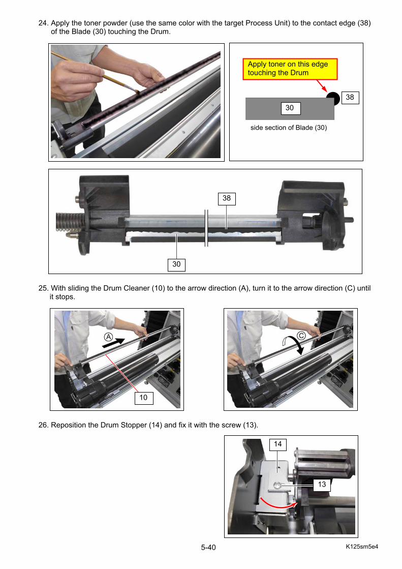
K125sm5e4 5-40
24. Apply the toner powder (use the same color with the target Process Unit) to the contact edge (38) of the Blade (30) touching the Drum. 25. With sliding the Drum Cleaner (10) to the arrow direction (A), turn it to the arrow direction (C) until
it stops. 26. Reposition the Drum Stopper (14) and fix it with the screw (13).
5
30 38
Apply toner on this edge touching the Drum
30
38
side section of Blade (30)
10
13
14
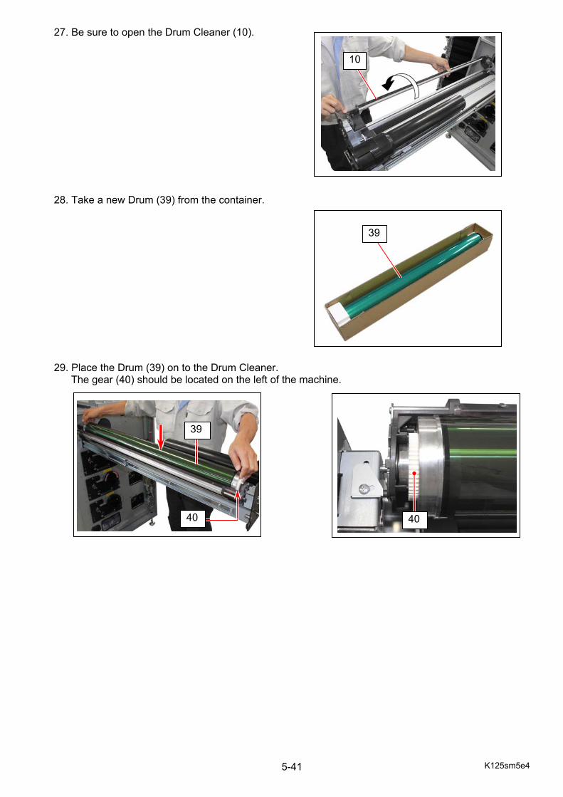
K125sm5e4 5-41
27. Be sure to open the Drum Cleaner (10). 28. Take a new Drum (39) from the container. 29. Place the Drum (39) on to the Drum Cleaner.
The gear (40) should be located on the left of the machine.
10
39
39
40
40
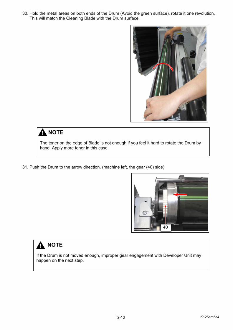
K125sm5e4 5-42
30. Hold the metal areas on both ends of the Drum (Avoid the green surface), rotate it one revolution. This will match the Cleaning Blade with the Drum surface. 31. Push the Drum to the arrow direction. (machine left, the gear (40) side)
NOTE The toner on the edge of Blade is not enough if you feel it hard to rotate the Drum by hand. Apply more toner in this case.
NOTE If the Drum is not moved enough, improper gear engagement with Developer Unit may happen on the next step.
40
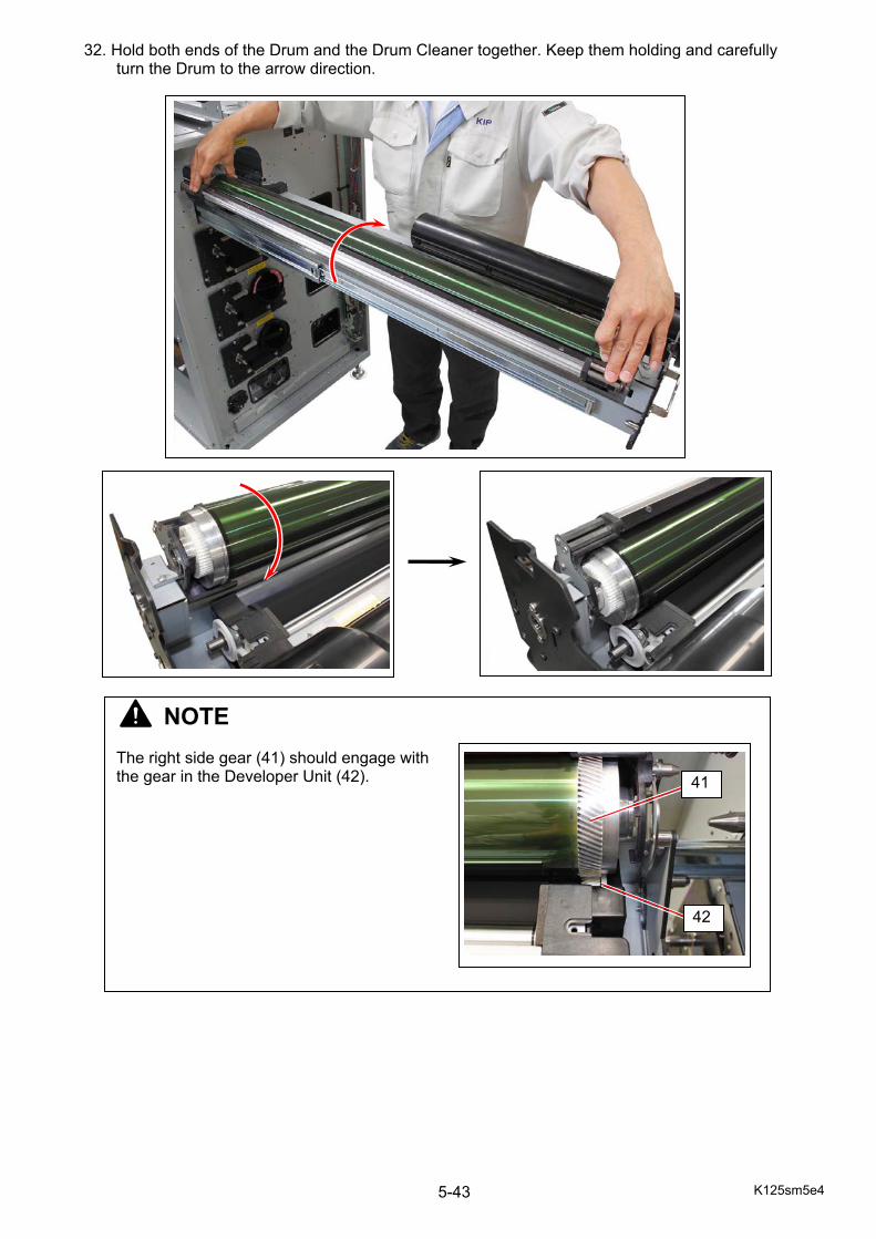
K125sm5e4 5-43
32. Hold both ends of the Drum and the Drum Cleaner together. Keep them holding and carefully turn the Drum to the arrow direction.
NOTE The right side gear (41) should engage with the gear in the Developer Unit (42).
41
42
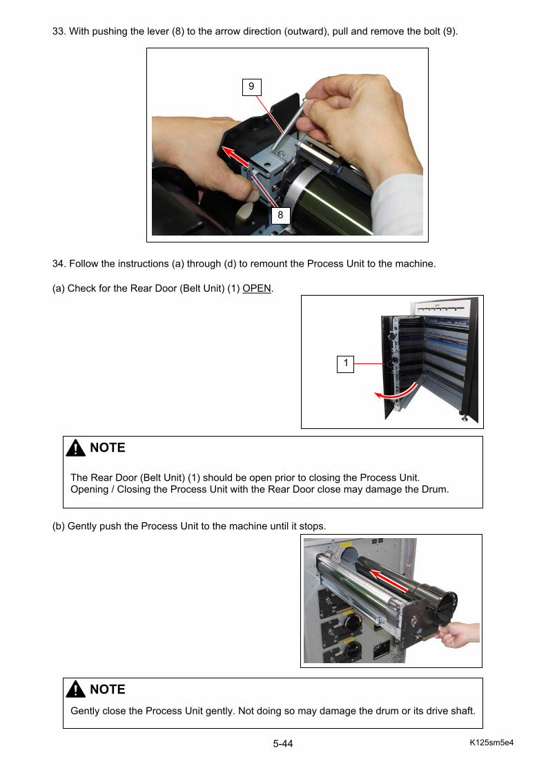
K125sm5e4 5-44
33. With pushing the lever (8) to the arrow direction (outward), pull and remove the bolt (9). 34. Follow the instructions (a) through (d) to remount the Process Unit to the machine. (a) Check for the Rear Door (Belt Unit) (1) OPEN.
(b) Gently push the Process Unit to the machine until it stops.
NOTE
The Rear Door (Belt Unit) (1) should be open prior to closing the Process Unit. Opening / Closing the Process Unit with the Rear Door close may damage the Drum.
1
NOTE
Gently close the Process Unit gently. Not doing so may damage the drum or its drive shaft.
8
9
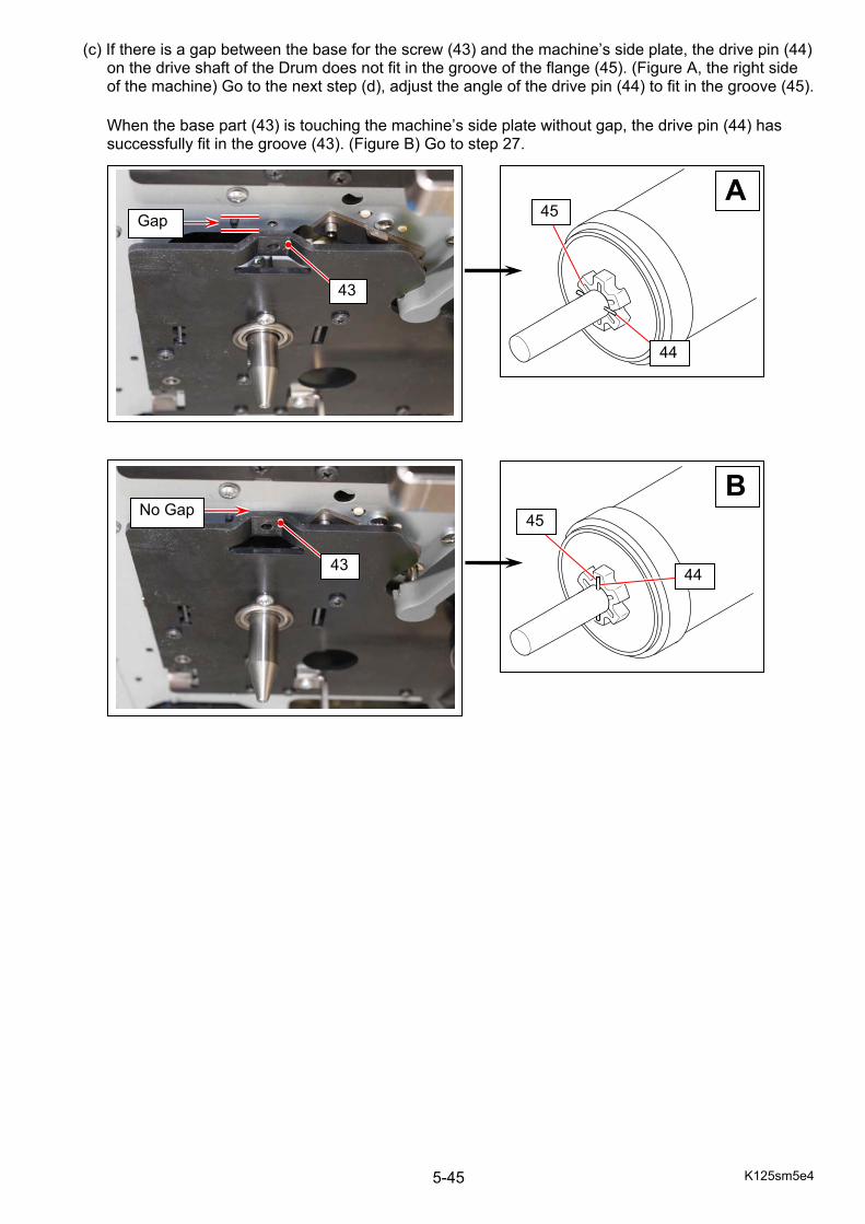
K125sm5e4 5-45
(c) If there is a gap between the base for the screw (43) and the machine’s side plate, the drive pin (44) on the drive shaft of the Drum does not fit in the groove of the flange (45). (Figure A, the right side of the machine) Go to the next step (d), adjust the angle of the drive pin (44) to fit in the groove (45). When the base part (43) is touching the machine’s side plate without gap, the drive pin (44) has successfully fit in the groove (43). (Figure B) Go to step 27.
Gap
43
44
45A
45
44
B
No Gap
43
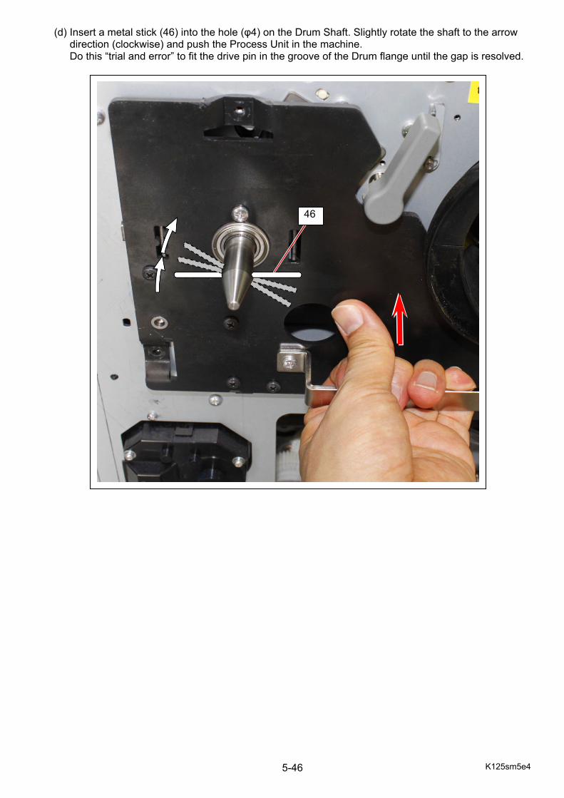
K125sm5e4 5-46
(d) Insert a metal stick (46) into the hole (φ4) on the Drum Shaft. Slightly rotate the shaft to the arrow direction (clockwise) and push the Process Unit in the machine. Do this “trial and error” to fit the drive pin in the groove of the Drum flange until the gap is resolved.
46
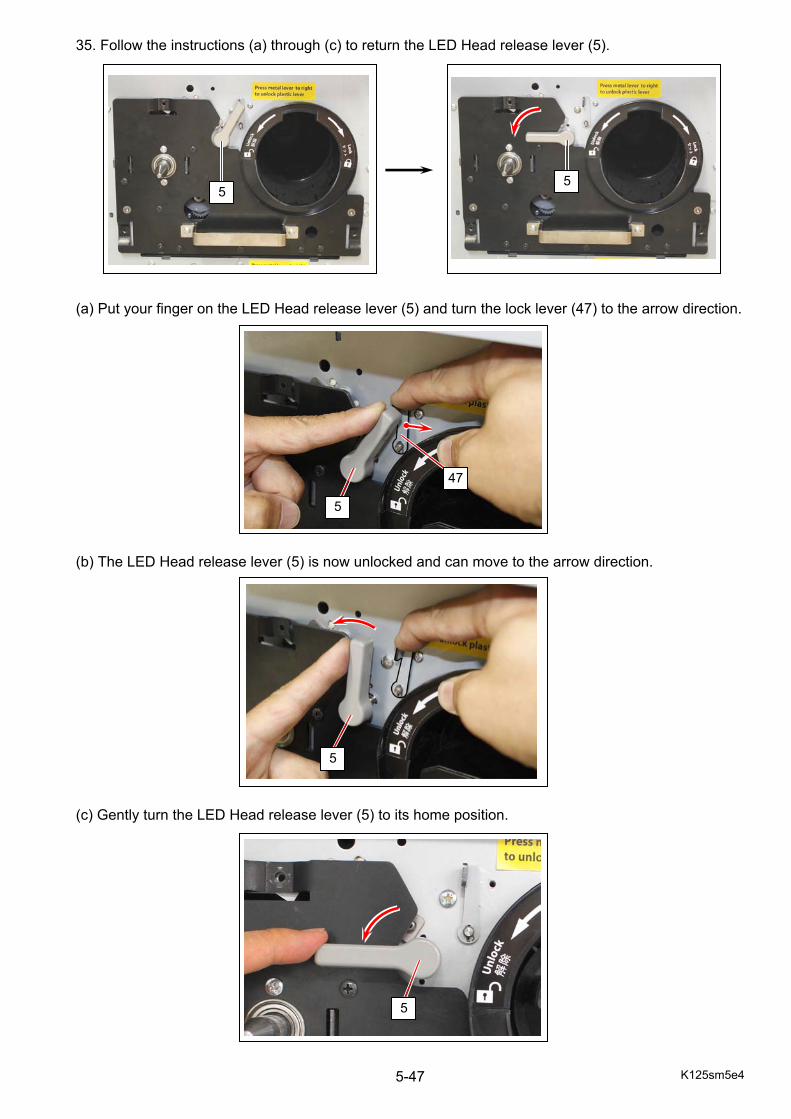
K125sm5e4 5-47
35. Follow the instructions (a) through (c) to return the LED Head release lever (5).
(a) Put your finger on the LED Head release lever (5) and turn the lock lever (47) to the arrow direction.
(b) The LED Head release lever (5) is now unlocked and can move to the arrow direction.
(c) Gently turn the LED Head release lever (5) to its home position.
5
5
47
5
5 5

K125sm5e4 5-48
36. Fix the Process Unit with 3 screws (3). For the screw on top, reinstall the stopper (4) together.
37. When setup of all the Process Unit of Yellow / Magenta / Cyan / Black is finished, close the Rear
Door (Belt Unit) (4).
1
3
3 3
3
4
4
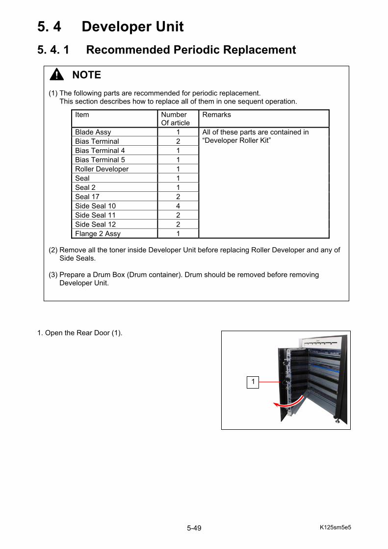
K125sm5e5 5-49
5. 4 Developer Unit
5. 4. 1 Recommended Periodic Replacement 1. Open the Rear Door (1).
NOTE (1) The following parts are recommended for periodic replacement.
This section describes how to replace all of them in one sequent operation. (2) Remove all the toner inside Developer Unit before replacing Roller Developer and any of
Side Seals. (3) Prepare a Drum Box (Drum container). Drum should be removed before removing
Developer Unit.
Item Number Of article
Remarks
Blade Assy 1 All of these parts are contained in “Developer Roller Kit” Bias Terminal 2
Bias Terminal 4 1 Bias Terminal 5 1 Roller Developer 1 Seal 1 Seal 2 1 Seal 17 2 Side Seal 10 4 Side Seal 11 2 Side Seal 12 2 Flange 2 Assy 1
1
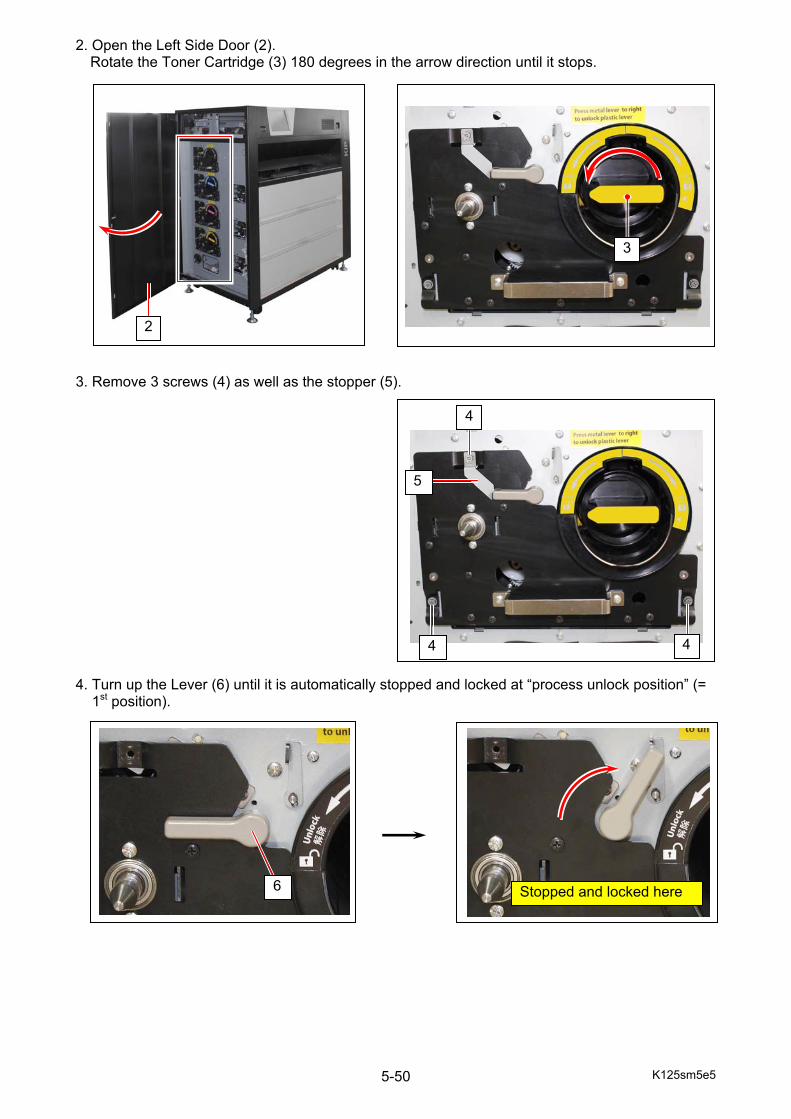
K125sm5e5 5-50
2. Open the Left Side Door (2). Rotate the Toner Cartridge (3) 180 degrees in the arrow direction until it stops.
3. Remove 3 screws (4) as well as the stopper (5). 4. Turn up the Lever (6) until it is automatically stopped and locked at “process unlock position” (= 1st position).
6
2
Stopped and locked here
3
4 4
4
5
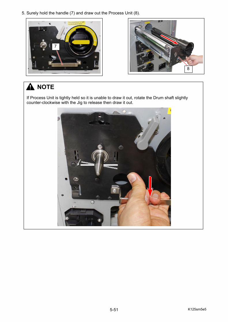
K125sm5e5 5-51
5. Surely hold the handle (7) and draw out the Process Unit (8).
NOTE If Process Unit is tightly held so it is unable to draw it out, rotate the Drum shaft slightly counter-clockwise with the Jig to release then draw it out.
8
7
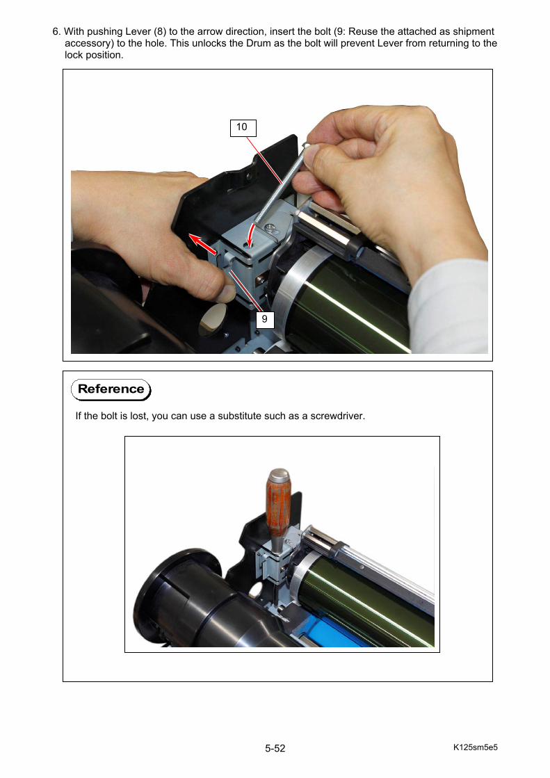
K125sm5e5 5-52
6. With pushing Lever (8) to the arrow direction, insert the bolt (9: Reuse the attached as shipment accessory) to the hole. This unlocks the Drum as the bolt will prevent Lever from returning to the lock position.
If the bolt is lost, you can use a substitute such as a screwdriver.
Reference
9
10

K125sm5e5 5-53
7. With firmly holding both ends of Drum Cleaner Unit (11) and Drum (12) together by both hands, gently move them up in the direction of arrow until they are stopped by the metal stopper. 8. With firmly hold both flanges (13), bring up and remove the Drum from the Process unit.
12
13
13
NOTE Keep the Drum in the Drum Box. Do not expose it to the light so long time.
11
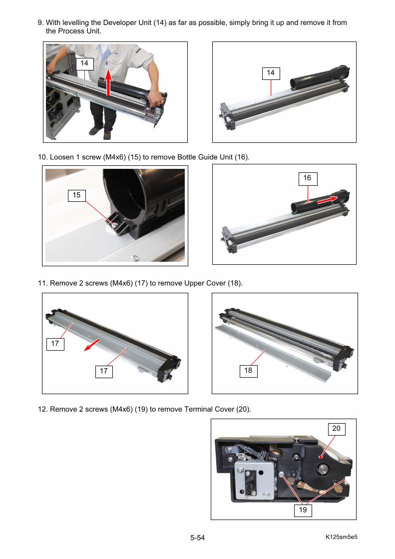
K125sm5e5 5-54
9. With levelling the Developer Unit (14) as far as possible, simply bring it up and remove it from the Process Unit. 10. Loosen 1 screw (M4x6) (15) to remove Bottle Guide Unit (16). 11. Remove 2 screws (M4x6) (17) to remove Upper Cover (18). 12. Remove 2 screws (M4x6) (19) to remove Terminal Cover (20).
14 14
15
17
18
17
16
19
20
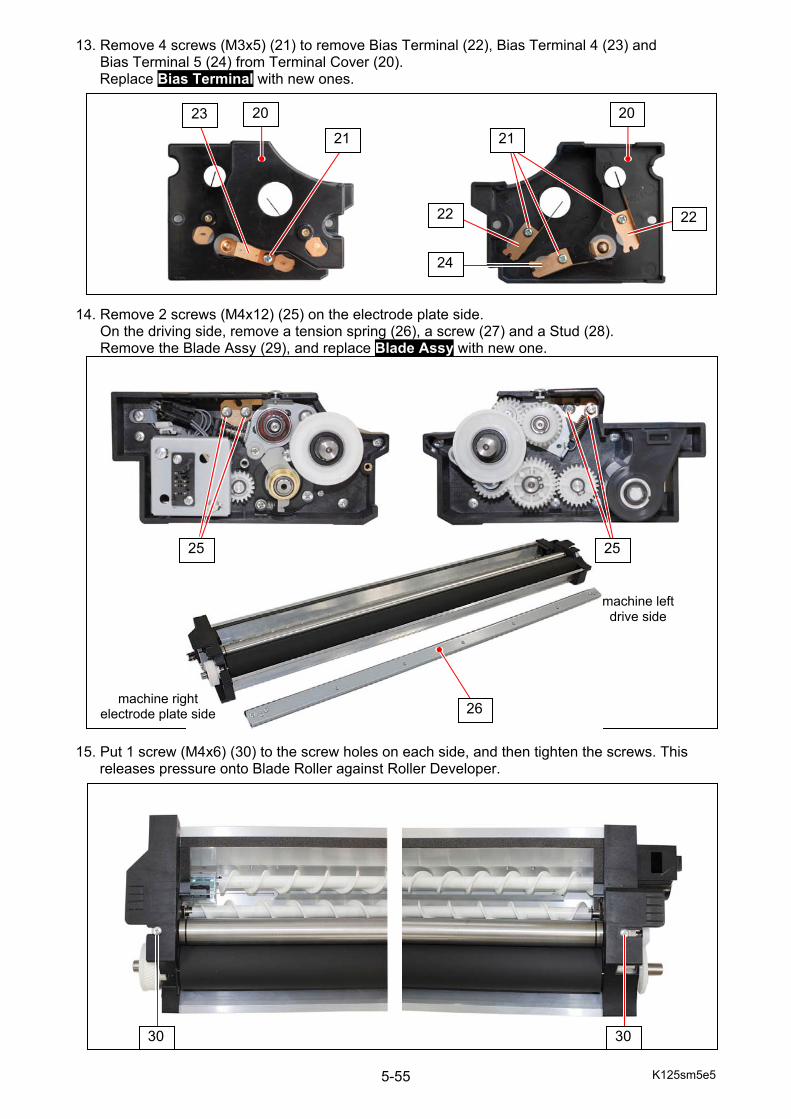
K125sm5e5 5-55
13. Remove 4 screws (M3x5) (21) to remove Bias Terminal (22), Bias Terminal 4 (23) and Bias Terminal 5 (24) from Terminal Cover (20).
Replace Bias Terminal with new ones. 14. Remove 2 screws (M4x12) (25) on the electrode plate side. On the driving side, remove a tension spring (26), a screw (27) and a Stud (28). Remove the Blade Assy (29), and replace Blade Assy with new one. 15. Put 1 screw (M4x6) (30) to the screw holes on each side, and then tighten the screws. This
releases pressure onto Blade Roller against Roller Developer.
30 30
26machine right
electrode plate side
machine leftdrive side
21 21
22 22
20 23 20
24
25 25
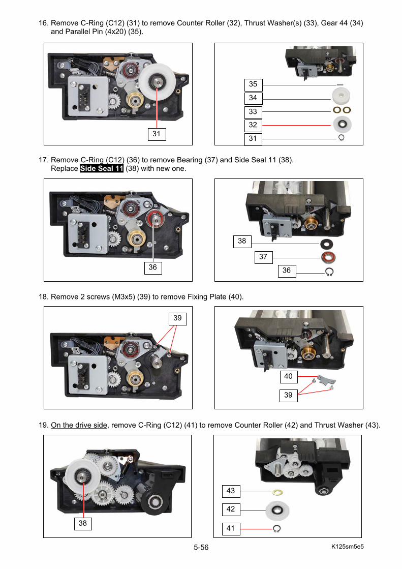
K125sm5e5 5-56
16. Remove C-Ring (C12) (31) to remove Counter Roller (32), Thrust Washer(s) (33), Gear 44 (34) and Parallel Pin (4x20) (35). 17. Remove C-Ring (C12) (36) to remove Bearing (37) and Side Seal 11 (38). Replace Side Seal 11 (38) with new one. 18. Remove 2 screws (M3x5) (39) to remove Fixing Plate (40). 19. On the drive side, remove C-Ring (C12) (41) to remove Counter Roller (42) and Thrust Washer (43).
42
41
43
31
36
39
38
35
31
32
33
38
37
36
39
40
34
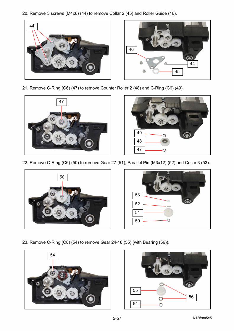
K125sm5e5 5-57
20. Remove 3 screws (M4x6) (44) to remove Collar 2 (45) and Roller Guide (46). 21. Remove C-Ring (C6) (47) to remove Counter Roller 2 (48) and C-Ring (C6) (49). 22. Remove C-Ring (C6) (50) to remove Gear 27 (51), Parallel Pin (M3x12) (52) and Collar 3 (53). 23. Remove C-Ring (C8) (54) to remove Gear 24-18 (55) (with Bearing (56)).
45
46
44
47
48
49
54
55
50
51
52
53
44
47
56
50
54
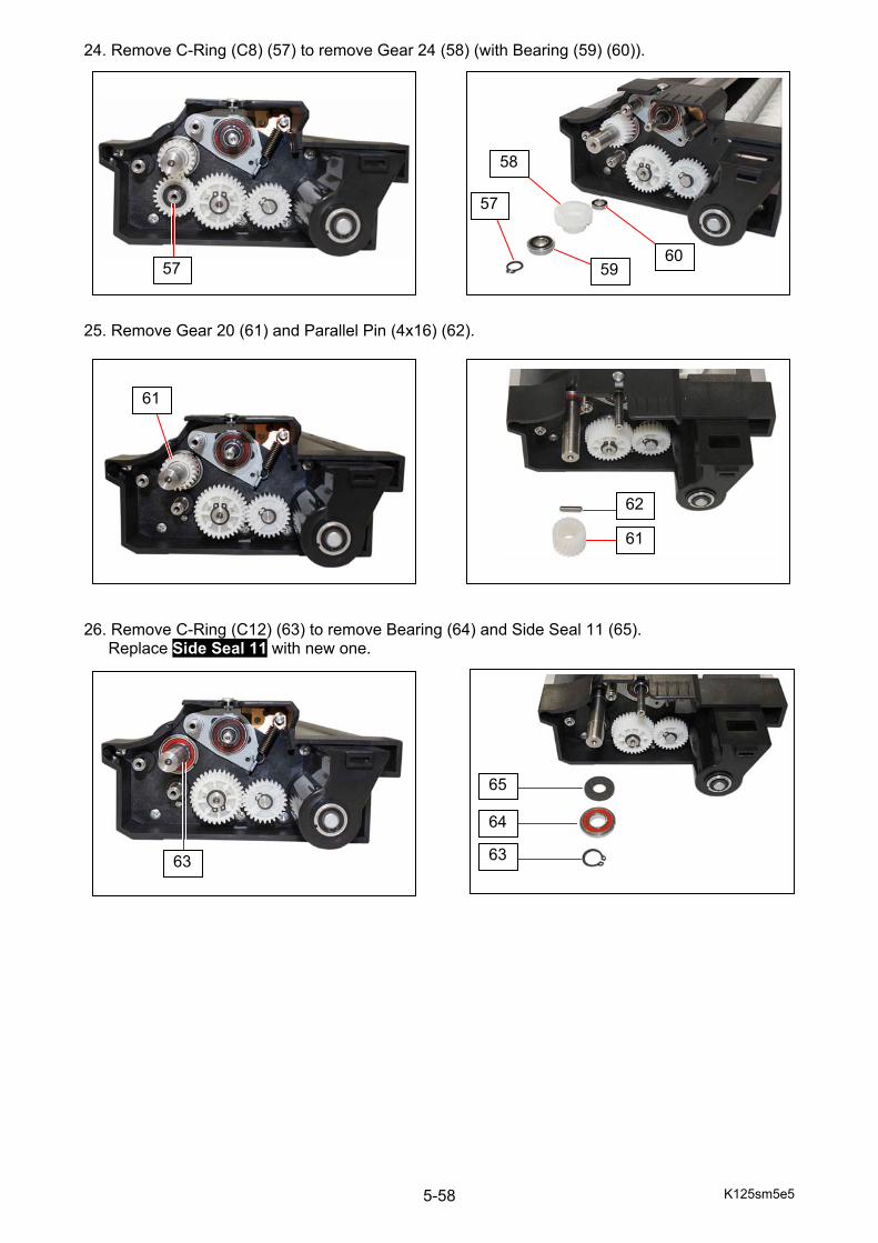
K125sm5e5 5-58
24. Remove C-Ring (C8) (57) to remove Gear 24 (58) (with Bearing (59) (60)). 25. Remove Gear 20 (61) and Parallel Pin (4x16) (62). 26. Remove C-Ring (C12) (63) to remove Bearing (64) and Side Seal 11 (65).
Replace Side Seal 11 with new one.
63
64
65
62
61
57
61
63
57
58
5960
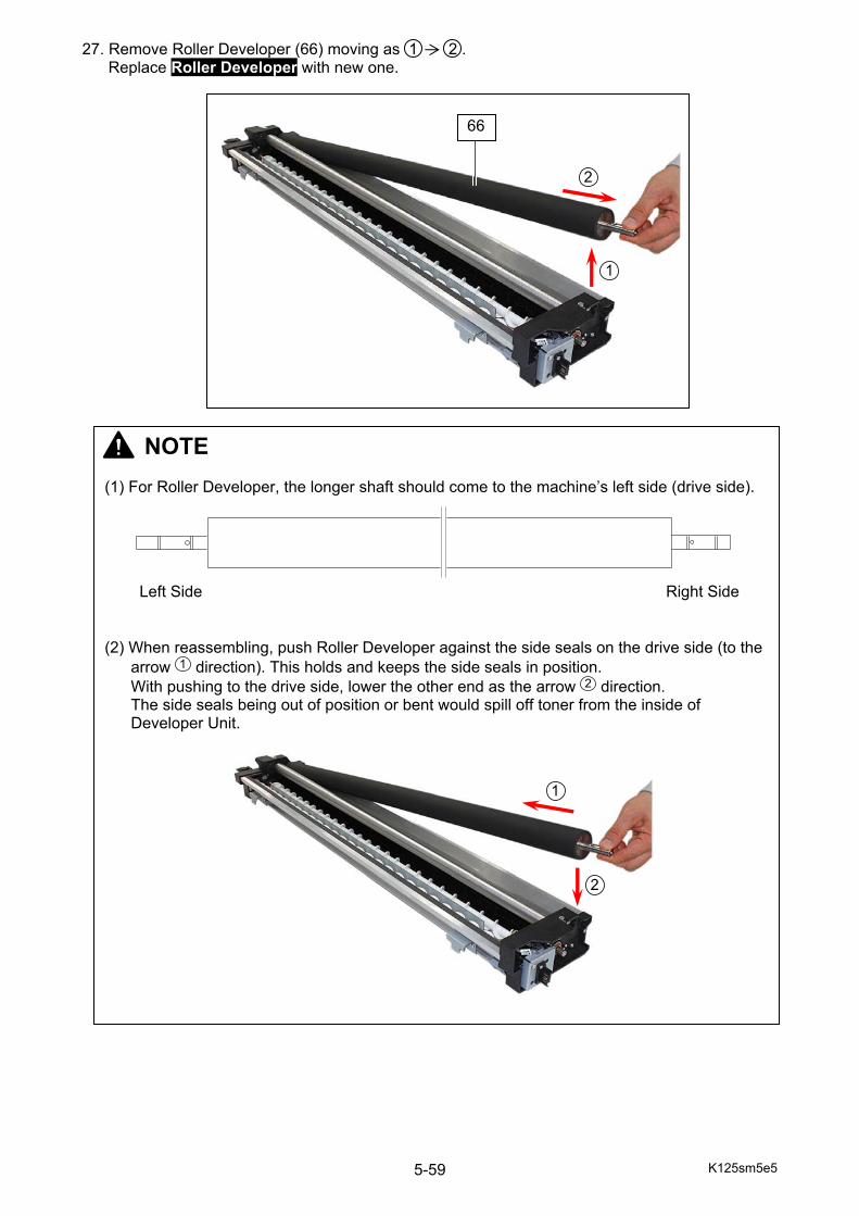
K125sm5e5 5-59
27. Remove Roller Developer (66) moving as 1 2 . Replace Roller Developer with new one.
66
NOTE (1) For Roller Developer, the longer shaft should come to the machine’s left side (drive side).
(2) When reassembling, push Roller Developer against the side seals on the drive side (to the
arrow direction). This holds and keeps the side seals in position. With pushing to the drive side, lower the other end as the arrow direction. The side seals being out of position or bent would spill off toner from the inside of Developer Unit.
Right Side Left Side
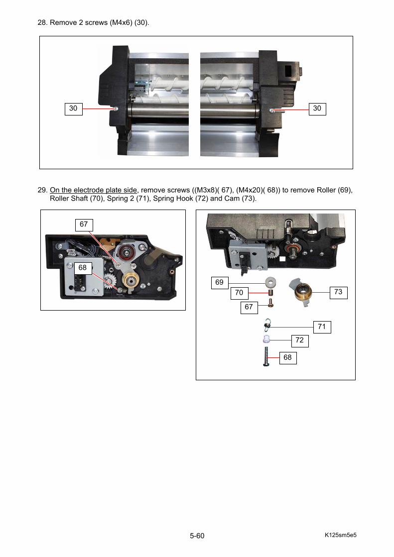
K125sm5e5 5-60
28. Remove 2 screws (M4x6) (30).
29. On the electrode plate side, remove screws ((M3x8)( 67), (M4x20)( 68)) to remove Roller (69), Roller Shaft (70), Spring 2 (71), Spring Hook (72) and Cam (73).
30 30
67
68
67
7069
73
68
72
71
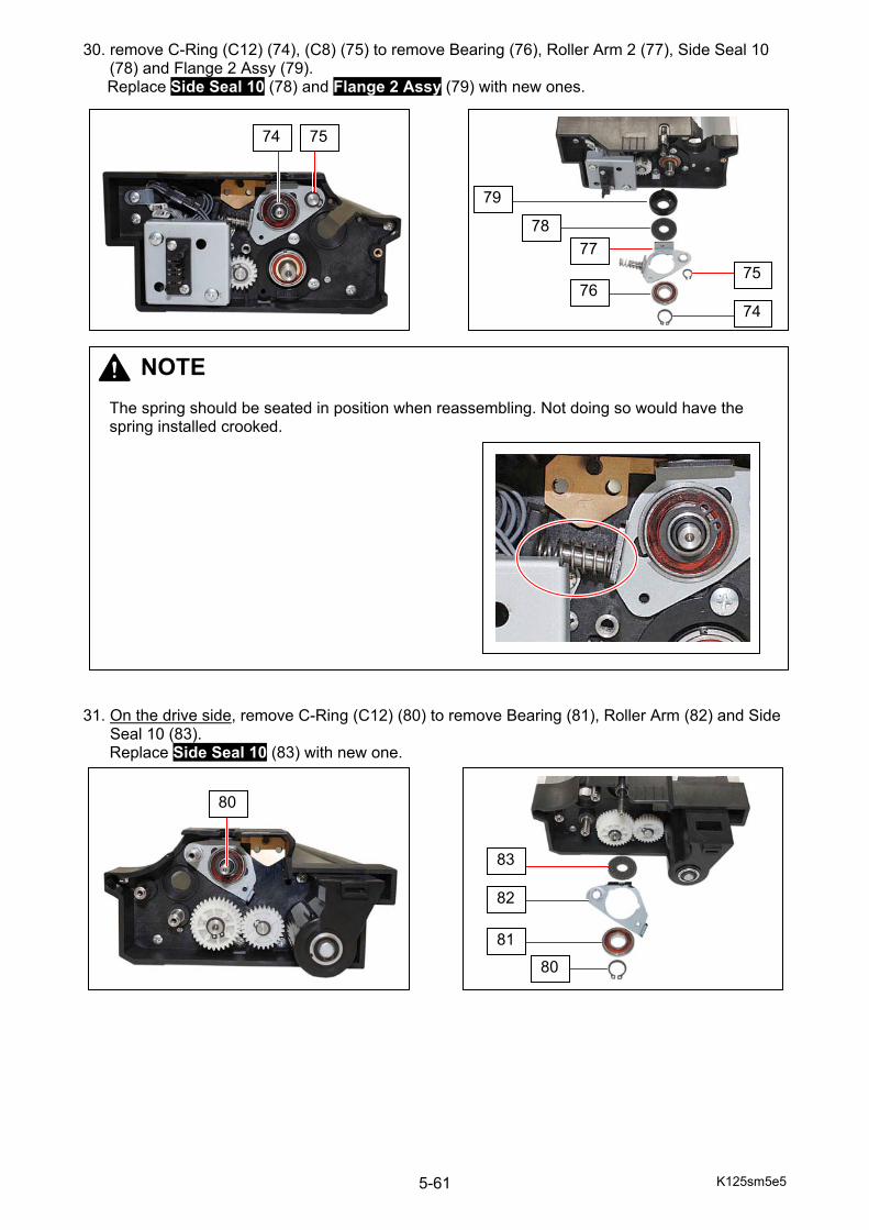
K125sm5e5 5-61
30. remove C-Ring (C12) (74), (C8) (75) to remove Bearing (76), Roller Arm 2 (77), Side Seal 10 (78) and Flange 2 Assy (79). Replace Side Seal 10 (78) and Flange 2 Assy (79) with new ones.
31. On the drive side, remove C-Ring (C12) (80) to remove Bearing (81), Roller Arm (82) and Side Seal 10 (83).
Replace Side Seal 10 (83) with new one.
74
7576
7778
79
74 75
NOTE The spring should be seated in position when reassembling. Not doing so would have the spring installed crooked.
76
80
80
81
82
83
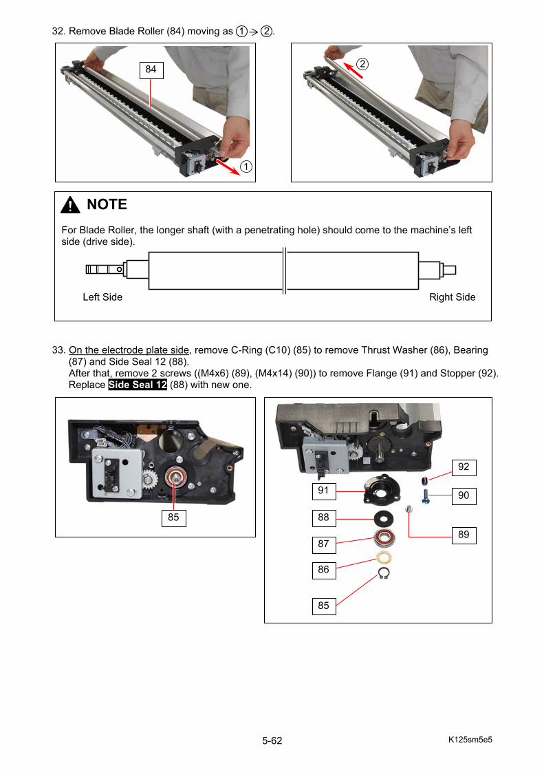
K125sm5e5 5-62
32. Remove Blade Roller (84) moving as 1 2 .
33. On the electrode plate side, remove C-Ring (C10) (85) to remove Thrust Washer (86), Bearing
(87) and Side Seal 12 (88). After that, remove 2 screws ((M4x6) (89), (M4x14) (90)) to remove Flange (91) and Stopper (92).
Replace Side Seal 12 (88) with new one.
84
NOTE For Blade Roller, the longer shaft (with a penetrating hole) should come to the machine’s left side (drive side).
Right Side Left Side
85
89
85
86
87
88
90
92
91
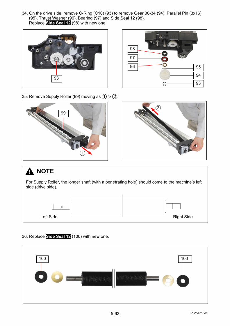
K125sm5e5 5-63
34. On the drive side, remove C-Ring (C10) (93) to remove Gear 30-34 (94), Parallel Pin (3x16) (95), Thrust Washer (96), Bearing (97) and Side Seal 12 (98). Replace Side Seal 12 (98) with new one.
35. Remove Supply Roller (99) moving as 1 2 .
36. Replace Side Seal 12 (100) with new one.
93
95
94
93
96
98
97
99
NOTE For Supply Roller, the longer shaft (with a penetrating hole) should come to the machine’s left side (drive side).
Right Side Left Side
100 100
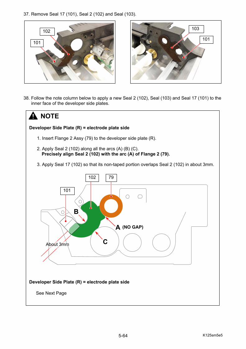
K125sm5e5 5-64
37. Remove Seal 17 (101), Seal 2 (102) and Seal (103). 38. Follow the note column below to apply a new Seal 2 (102), Seal (103) and Seal 17 (101) to the inner face of the developer side plates.
101
102 103
101
NOTE Developer Side Plate (R) = electrode plate side
1. Insert Flange 2 Assy (79) to the developer side plate (R). 2. Apply Seal 2 (102) along all the arcs (A) (B) (C).
Precisely align Seal 2 (102) with the arc (A) of Flange 2 (79). 3. Apply Seal 17 (102) so that its non-taped portion overlaps Seal 2 (102) in about 3mm.
Developer Side Plate (R) = electrode plate side
See Next Page
About 3mm
A
C
B
79102
101
(NO GAP)

K125sm5e5 5-65
NOTE Developer Side Plate (L) = drive side
1. Apply Seal (103) along the edge of the 2 holes (D) (E). 2. Apply Seal 17 (101) so that its non-taped portion overlaps Seal (103) in about 3mm.
103
101
DE
About 3mm
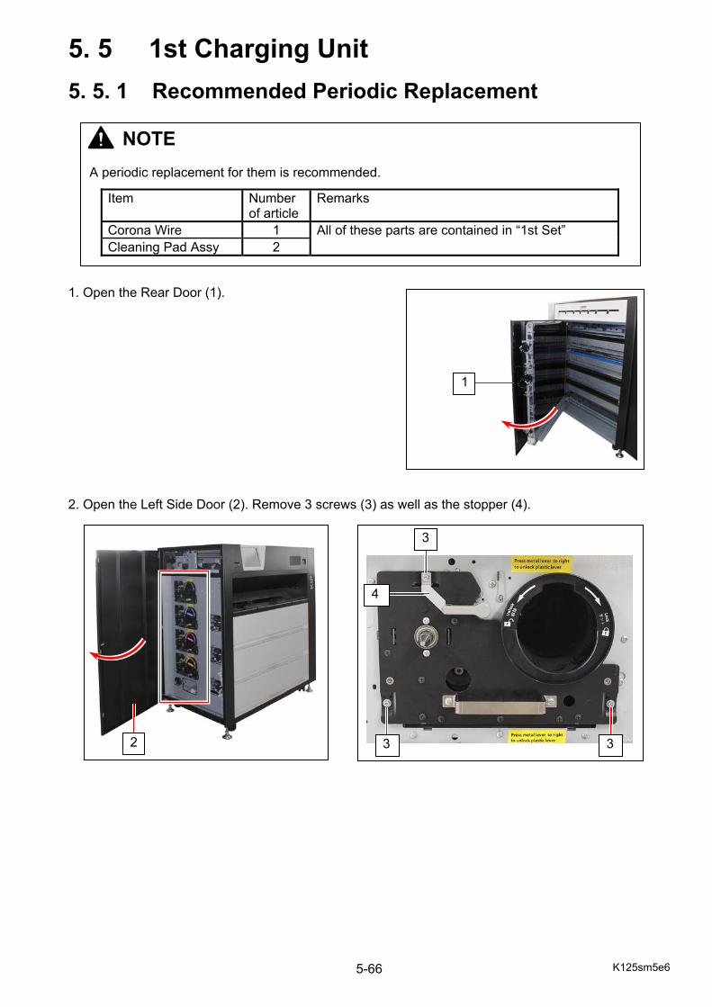
K125sm5e6 5-66
5. 5 1st Charging Unit
5. 5. 1 Recommended Periodic Replacement 1. Open the Rear Door (1). 2. Open the Left Side Door (2). Remove 3 screws (3) as well as the stopper (4).
NOTE A periodic replacement for them is recommended.
Item Number of article
Remarks
Corona Wire 1 All of these parts are contained in “1st Set” Cleaning Pad Assy 2
1
3 3
3
4
2
K125sm5e6 5-67
3. Turn up the Lever (5) until it is automatically stopped and locked at “process unlock position” (= 1st position). 4. Surely hold the handle (6) and draw out the Process Unit (7) full.
5 Stopped and locked here
NOTE If Process Unit is tightly held so it is unable to draw it out, rotate the Drum shaft slightly counter-clockwise with the Jig to release then draw it out.
6
7

K125sm5e6 5-68
5. Holding HV Head (8), gently draw 1st Charging Unit (9).
8
9
NOTE Carefully remove 1st Charging Unit from the machine. Do not fall or hit 1st Charging Unit to Drum as they are located close each other.
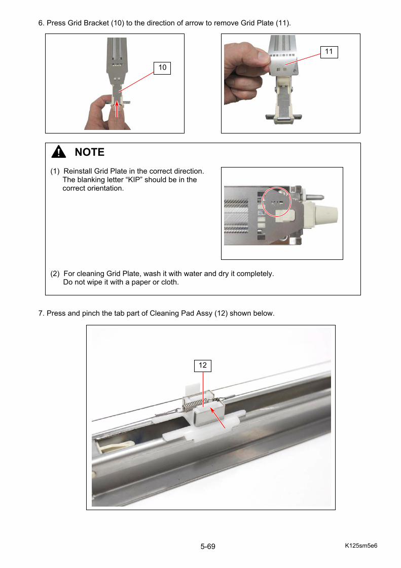
K125sm5e6 5-69
6. Press Grid Bracket (10) to the direction of arrow to remove Grid Plate (11). 7. Press and pinch the tab part of Cleaning Pad Assy (12) shown below.
NOTE (1) Reinstall Grid Plate in the correct direction.
The blanking letter “KIP” should be in the correct orientation.
(2) For cleaning Grid Plate, wash it with water and dry it completely.
Do not wipe it with a paper or cloth.
11
10
12
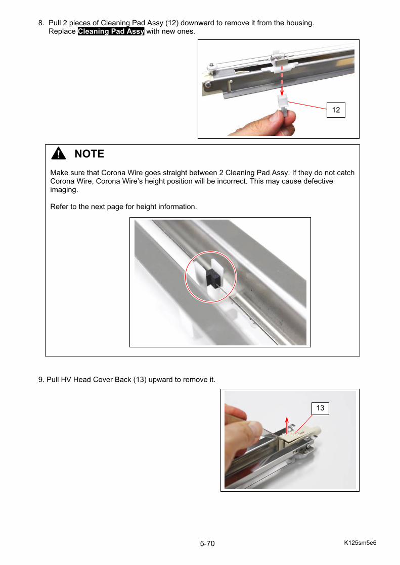
K125sm5e6 5-70
8. Pull 2 pieces of Cleaning Pad Assy (12) downward to remove it from the housing. Replace Cleaning Pad Assy with new ones. 9. Pull HV Head Cover Back (13) upward to remove it.
NOTE Make sure that Corona Wire goes straight between 2 Cleaning Pad Assy. If they do not catch Corona Wire, Corona Wire’s height position will be incorrect. This may cause defective imaging. Refer to the next page for height information.
12
13
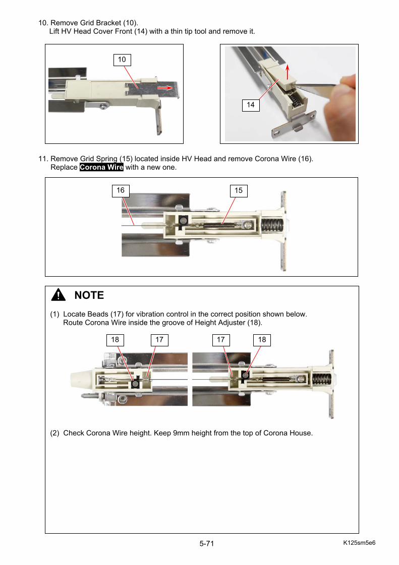
K125sm5e6 5-71
10. Remove Grid Bracket (10). Lift HV Head Cover Front (14) with a thin tip tool and remove it.
11. Remove Grid Spring (15) located inside HV Head and remove Corona Wire (16). Replace Corona Wire with a new one.
NOTE (1) Locate Beads (17) for vibration control in the correct position shown below.
Route Corona Wire inside the groove of Height Adjuster (18). (2) Check Corona Wire height. Keep 9mm height from the top of Corona House.
14
1516
17 18 18
10
17
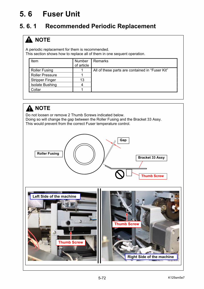
K125sm5e7 5-72
5. 6 Fuser Unit
5. 6. 1 Recommended Periodic Replacement
NOTE A periodic replacement for them is recommended. This section shows how to replace all of them in one sequent operation.
Item Number of article
Remarks
Roller Fusing 1 All of these parts are contained in “Fuser Kit” Roller Pressure 1 Stripper Finger 13 Isolate Bushing 4 Collar 1
NOTE
Do not loosen or remove 2 Thumb Screws indicated below. Doing so will change the gap between the Roller Fusing and the Bracket 33 Assy. This would prevent from the correct Fuser temperature control.
Gap
Bracket 33 Assy
Thumb Screw
Roller Fusing
Thumb Screw
Left Side of the machine
Right Side of the machine
Thumb Screw
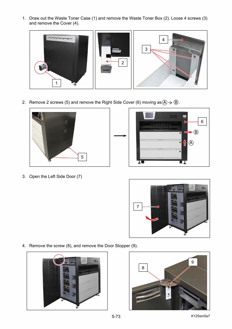
K125sm5e7 5-73
1. Draw out the Waste Toner Case (1) and remove the Waste Toner Box (2). Loose 4 screws (3)
and remove the Cover (4). 2. Remove 2 screws (5) and remove the Right Side Cover (6) moving as .
3. Open the Left Side Door (7) 4. Remove the screw (8), and remove the Door Stopper (9).
5
1
2
4
3
6
7
89
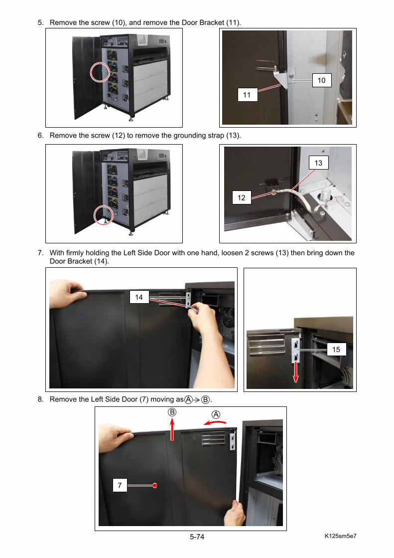
K125sm5e7 5-74
5. Remove the screw (10), and remove the Door Bracket (11).
6. Remove the screw (12) to remove the grounding strap (13). 7. With firmly holding the Left Side Door with one hand, loosen 2 screws (13) then bring down the
Door Bracket (14).
8. Remove the Left Side Door (7) moving as .
12
13
10
11
14
15
7
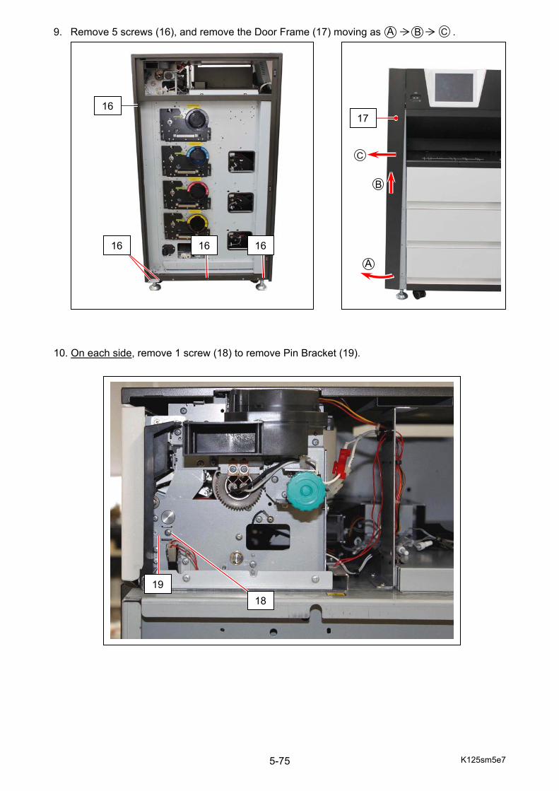
K125sm5e7 5-75
9. Remove 5 screws (16), and remove the Door Frame (17) moving as . 10. On each side, remove 1 screw (18) to remove Pin Bracket (19).
16
16 16 16
17
1819
K125sm5e7 5-76
11. Open the Fuser Exit Cover (20). 12. On each side, move the Lever (21) as for unlocking, and remove the Fuser Exit Cover. 13. Remove 2 screws (22) to remove per Stripper Finger Assy (23) from Stripping Nail Unit (24).
Replace Stripper Finger (25) with a new one.
20
21
24
22
23 23: in front of the white roller
25 25
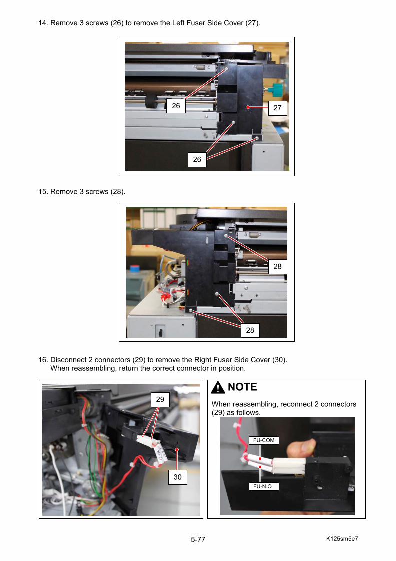
K125sm5e7 5-77
14. Remove 3 screws (26) to remove the Left Fuser Side Cover (27). 15. Remove 3 screws (28). 16. Disconnect 2 connectors (29) to remove the Right Fuser Side Cover (30). When reassembling, return the correct connector in position.
26
26
27
28
28
30
29NOTE
When reassembling, reconnect 2 connectors (29) as follows.
FU-N.O
FU-COM
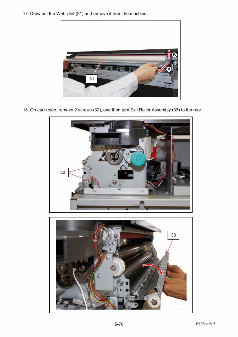
K125sm5e7 5-78
17. Draw out the Web Unit (31) and remove it from the machine. 18. On each side, remove 2 screws (32), and then turn Exit Roller Assembly (33) to the rear.
31
32
33
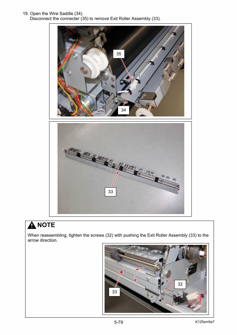
K125sm5e7 5-79
19. Open the Wire Saddle (34). Disconnect the connecter (35) to remove Exit Roller Assembly (33).
35
34
33
NOTE
When reassembling, tighten the screws (32) with pushing the Exit Roller Assembly (33) to the arrow direction.
33
32
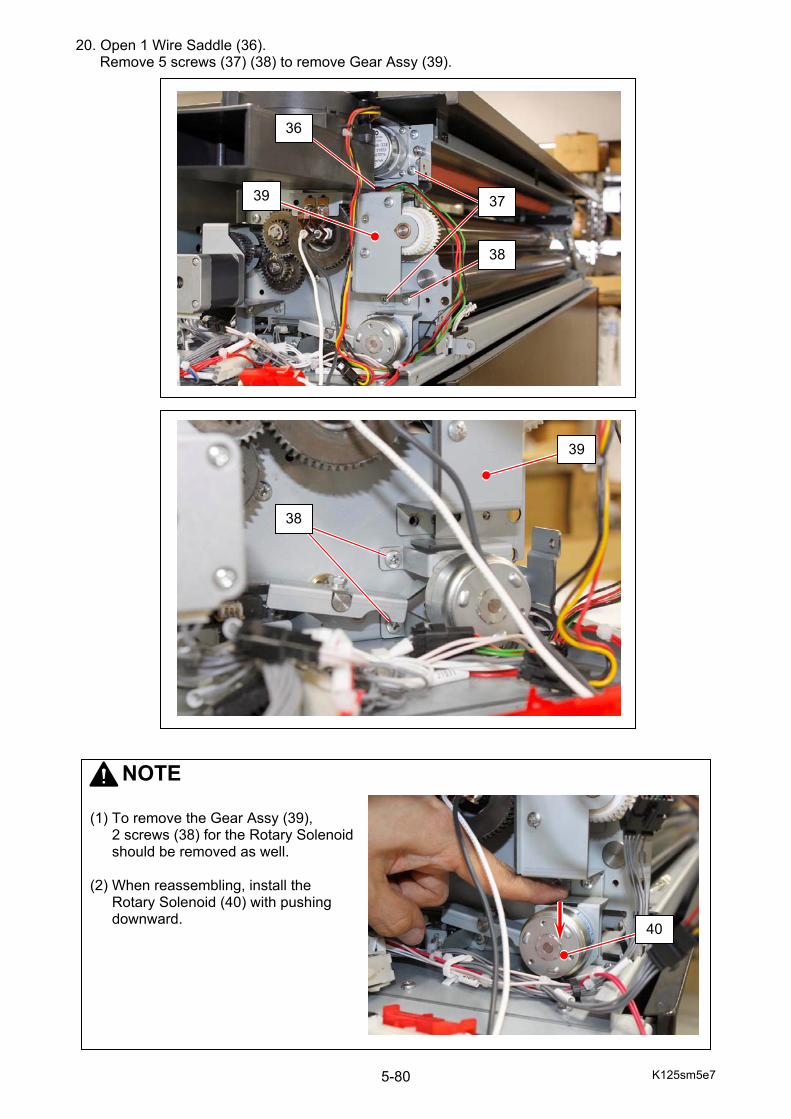
K125sm5e7 5-80
20. Open 1 Wire Saddle (36). Remove 5 screws (37) (38) to remove Gear Assy (39).
36
37
38
NOTE
(1) To remove the Gear Assy (39),
2 screws (38) for the Rotary Solenoid should be removed as well.
(2) When reassembling, install the
Rotary Solenoid (40) with pushing downward.
40
39
39
38
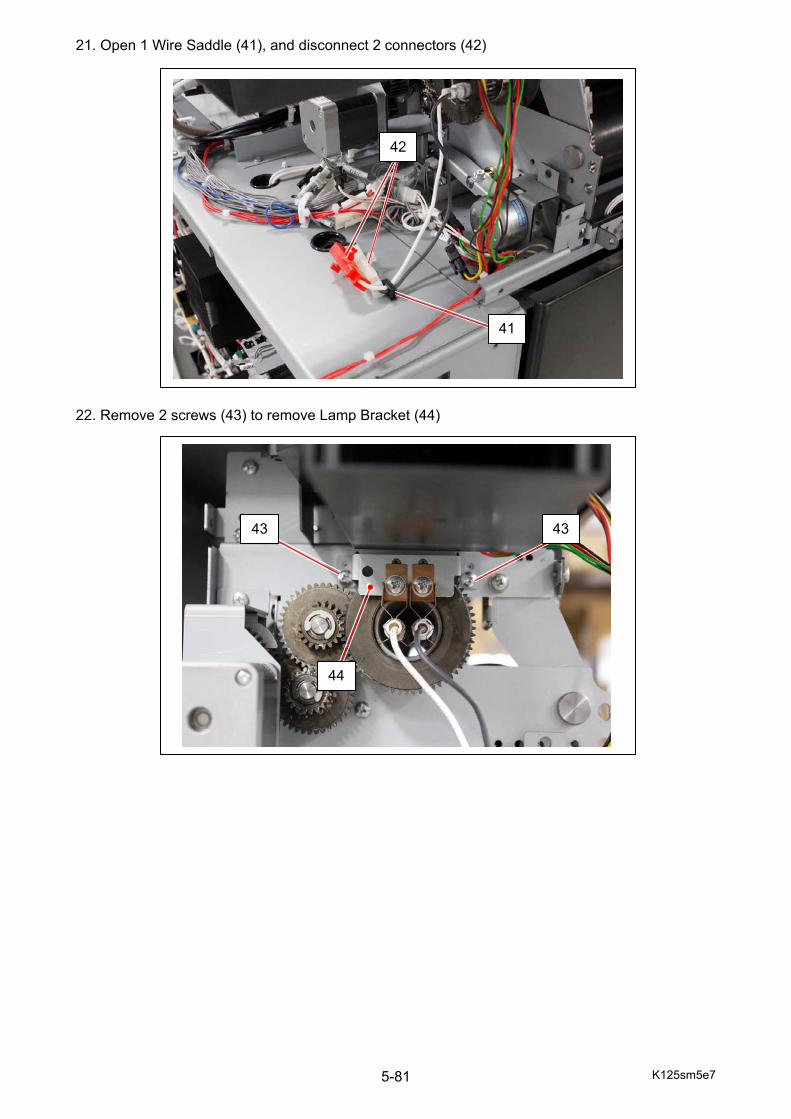
K125sm5e7 5-81
21. Open 1 Wire Saddle (41), and disconnect 2 connectors (42) 22. Remove 2 screws (43) to remove Lamp Bracket (44)
41
42
43 43
44
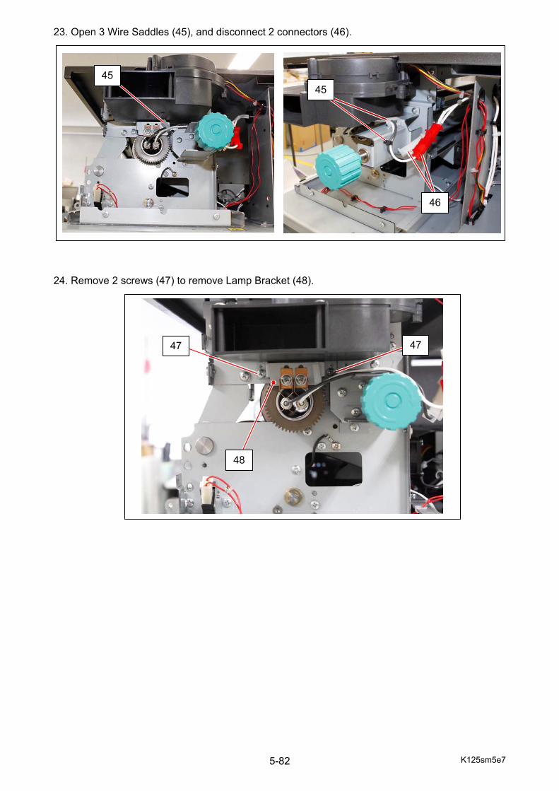
K125sm5e7 5-82
23. Open 3 Wire Saddles (45), and disconnect 2 connectors (46).
24. Remove 2 screws (47) to remove Lamp Bracket (48).
4545
46
47 47
48
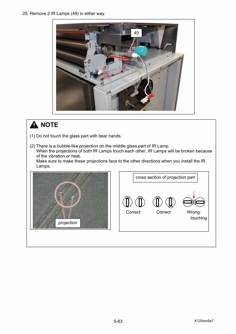
K125sm5e7 5-83
25. Remove 2 IR Lamps (49) in either way.
49
NOTE (1) Do not touch the glass part with bear hands. (2) There is a bubble-like projection on the middle glass part of IR Lamp.
When the projections of both IR Lamps touch each other, IR Lamps will be broken because of the vibration or heat. Make sure to make these projections face to the other directions when you install the IR Lamps.
cross section of projection part
projection
Correct Correct Wrong:touching
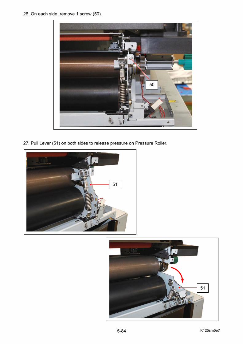
K125sm5e7 5-84
26. On each side, remove 1 screw (50). 27. Pull Lever (51) on both sides to release pressure on Pressure Roller.
50
51
51
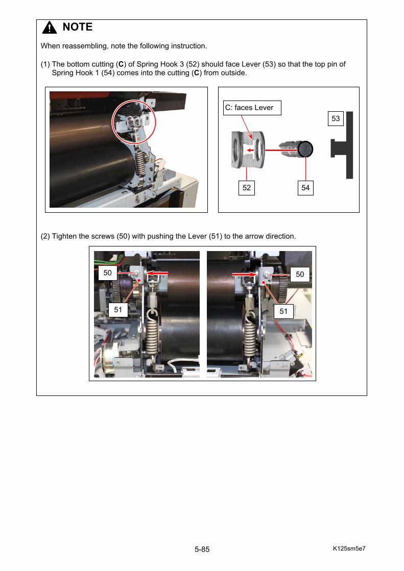
K125sm5e7 5-85
NOTE When reassembling, note the following instruction. (1) The bottom cutting (C) of Spring Hook 3 (52) should face Lever (53) so that the top pin of
Spring Hook 1 (54) comes into the cutting (C) from outside.
(2) Tighten the screws (50) with pushing the Lever (51) to the arrow direction.
53
52 54
C: faces Lever
50 50
51 51
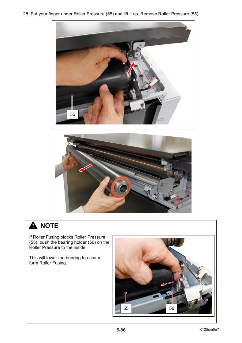
K125sm5e7 5-86
28. Put your finger under Roller Pressure (55) and lift it up. Remove Roller Pressure (55).
55
NOTE If Roller Fusing blocks Roller Pressure (55), push the bearing holder (56) on the Roller Pressure to the inside. This will lower the bearing to escape form Roller Fusing.
55 56
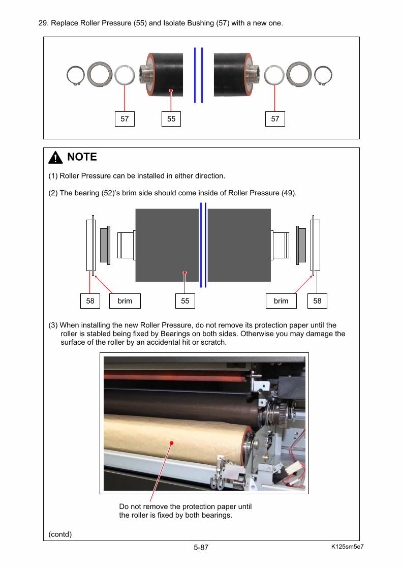
K125sm5e7 5-87
29. Replace Roller Pressure (55) and Isolate Bushing (57) with a new one.
5557 57
NOTE (1) Roller Pressure can be installed in either direction. (2) The bearing (52)’s brim side should come inside of Roller Pressure (49).
(3) When installing the new Roller Pressure, do not remove its protection paper until the roller is stabled being fixed by Bearings on both sides. Otherwise you may damage the surface of the roller by an accidental hit or scratch.
(contd)
58 58 brim brim 55
Do not remove the protection paper until the roller is fixed by both bearings.
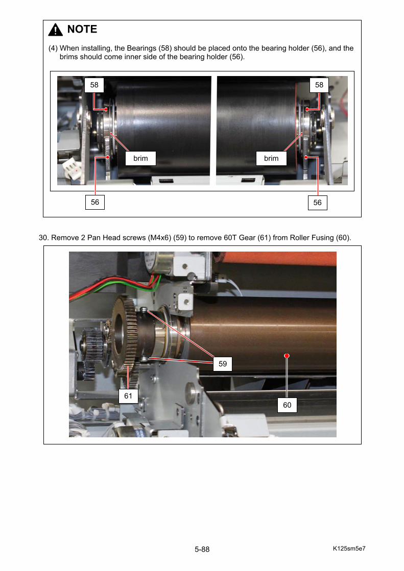
K125sm5e7 5-88
30. Remove 2 Pan Head screws (M4x6) (59) to remove 60T Gear (61) from Roller Fusing (60).
NOTE (4) When installing, the Bearings (58) should be placed onto the bearing holder (56), and the
brims should come inner side of the bearing holder (56).
brim brim
56
58 58
56
61
59
60
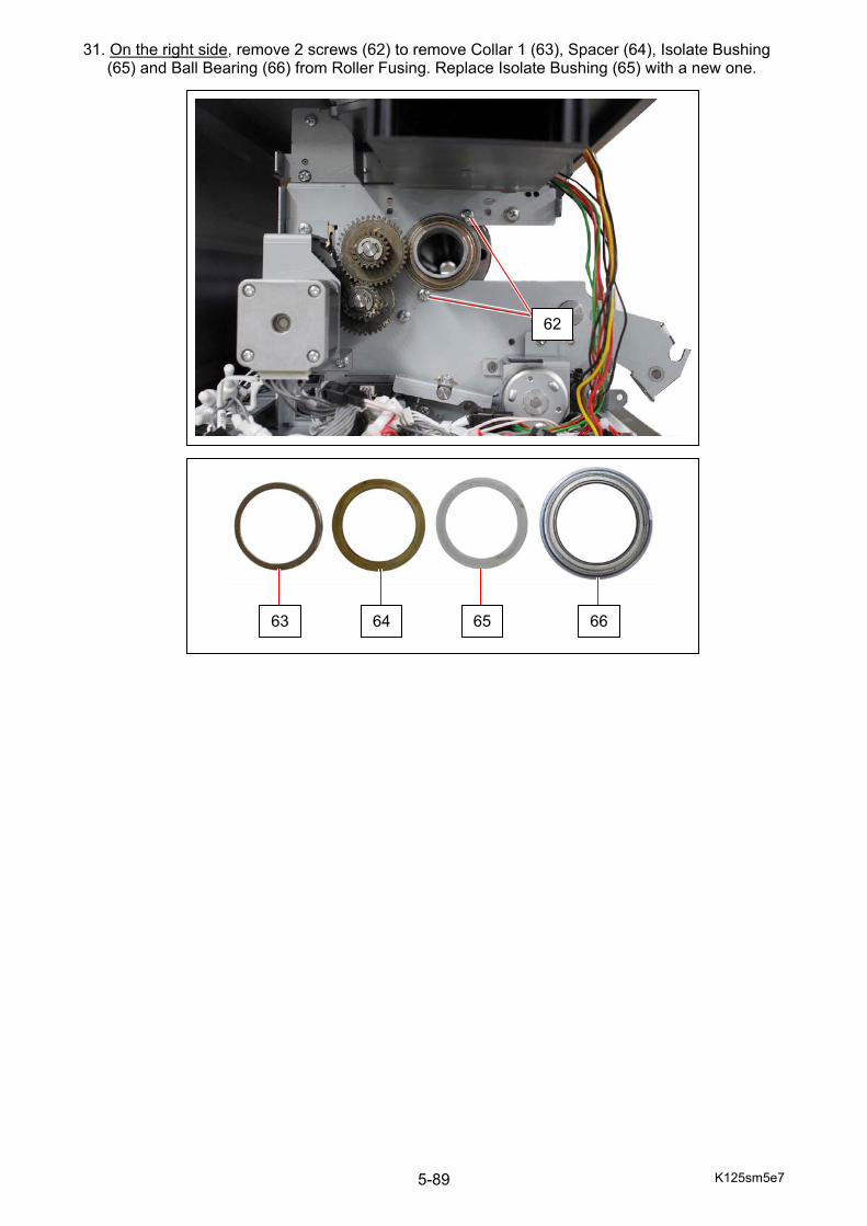
K125sm5e7 5-89
31. On the right side, remove 2 screws (62) to remove Collar 1 (63), Spacer (64), Isolate Bushing (65) and Ball Bearing (66) from Roller Fusing. Replace Isolate Bushing (65) with a new one.
62
63 64 65 66

K125sm5e7 5-90
32. On the left side, remove 2 Pan Head screws (M4x8) (67) to remove Spur Gear 50T (68), Spacer (69), Wave Washer (70) and Collar (71).
67
68
68 696969
7070 71 71
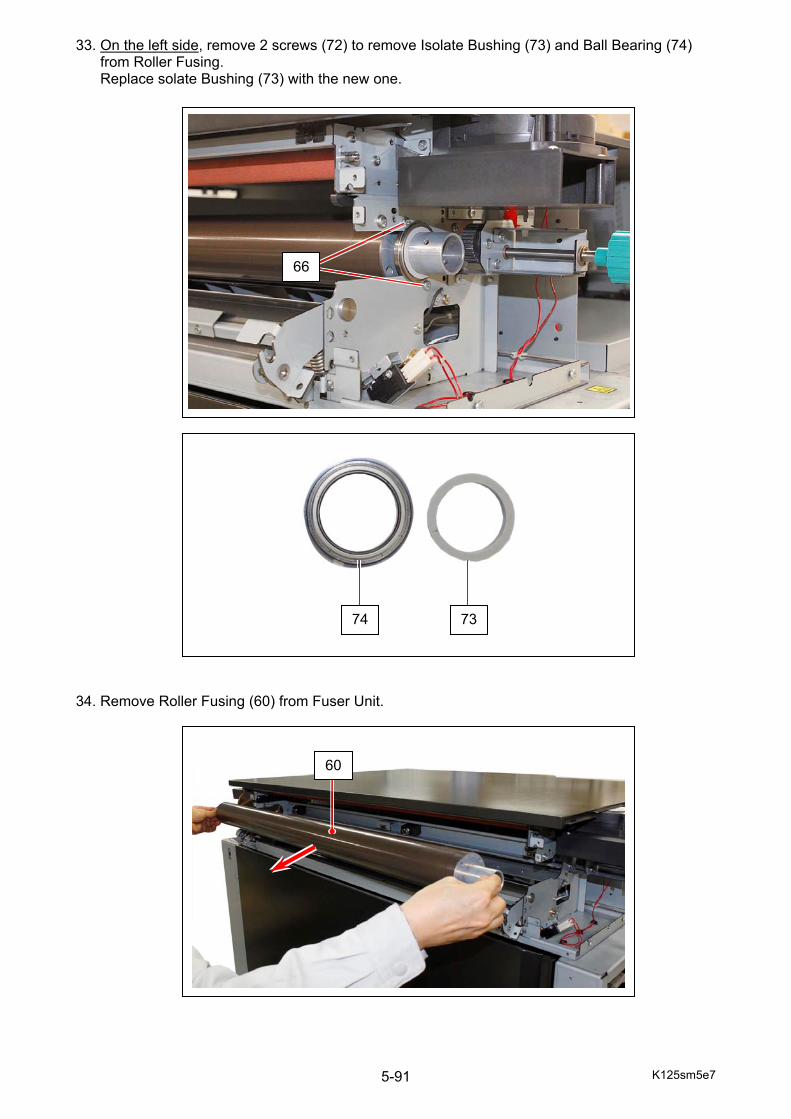
K125sm5e7 5-91
33. On the left side, remove 2 screws (72) to remove Isolate Bushing (73) and Ball Bearing (74) from Roller Fusing. Replace solate Bushing (73) with the new one. 34. Remove Roller Fusing (60) from Fuser Unit.
66
7374
60
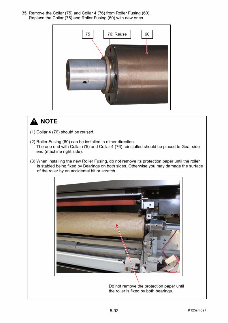
K125sm5e7 5-92
35. Remove the Collar (75) and Collar 4 (76) from Roller Fusing (60). Replace the Collar (75) and Roller Fusing (60) with new ones.
75 6076: Reuse
NOTE (1) Collar 4 (76) should be reused. (2) Roller Fusing (60) can be installed in either direction.
The one end with Collar (75) and Collar 4 (76) reinstalled should be placed to Gear side end (machine right side).
(3) When installing the new Roller Fusing, do not remove its protection paper until the roller
is stabled being fixed by Bearings on both sides. Otherwise you may damage the surface of the roller by an accidental hit or scratch.
Do not remove the protection paper until the roller is fixed by both bearings.
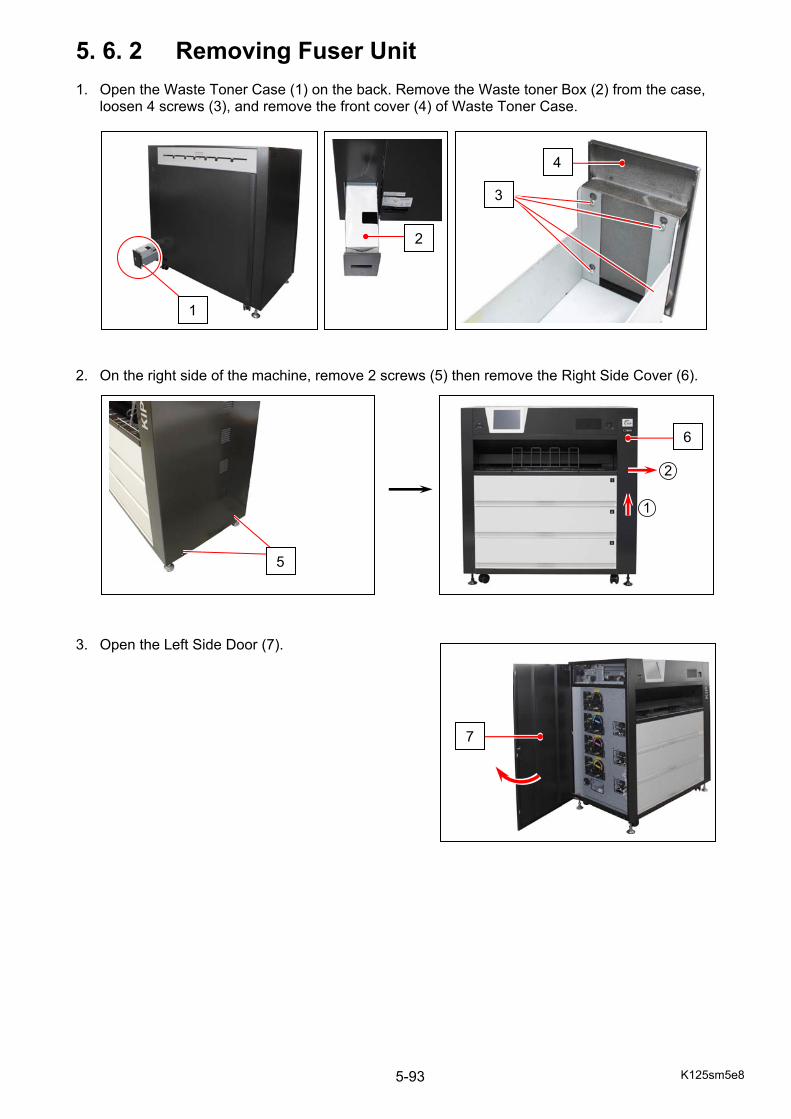
K125sm5e8 5-93
5. 6. 2 Removing Fuser Unit 1. Open the Waste Toner Case (1) on the back. Remove the Waste toner Box (2) from the case,
loosen 4 screws (3), and remove the front cover (4) of Waste Toner Case. 2. On the right side of the machine, remove 2 screws (5) then remove the Right Side Cover (6). 3. Open the Left Side Door (7).
5
1
2
4
3
7
6
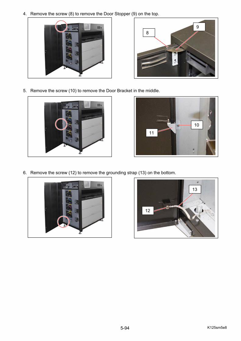
K125sm5e8 5-94
4. Remove the screw (8) to remove the Door Stopper (9) on the top. 5. Remove the screw (10) to remove the Door Bracket in the middle. 6. Remove the screw (12) to remove the grounding strap (13) on the bottom.
89
10
11
12
13
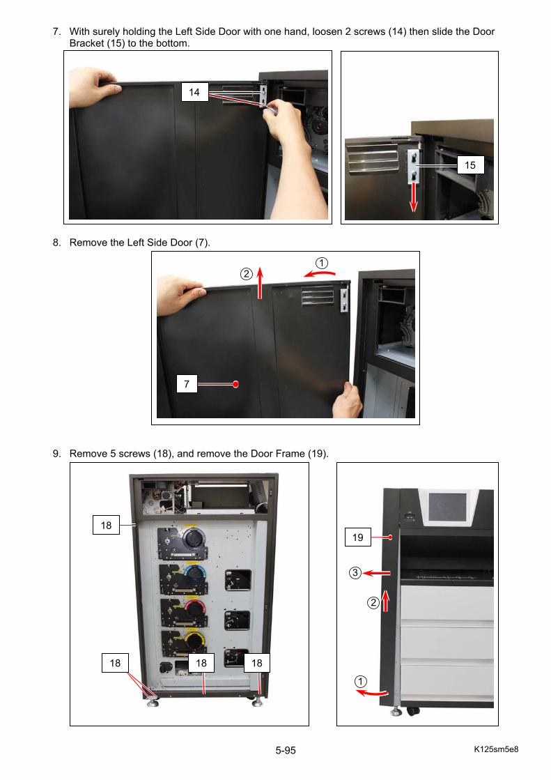
K125sm5e8 5-95
7. With surely holding the Left Side Door with one hand, loosen 2 screws (14) then slide the Door Bracket (15) to the bottom.
8. Remove the Left Side Door (7). 9. Remove 5 screws (18), and remove the Door Frame (19).
14
15
7
18
18 18 18
19
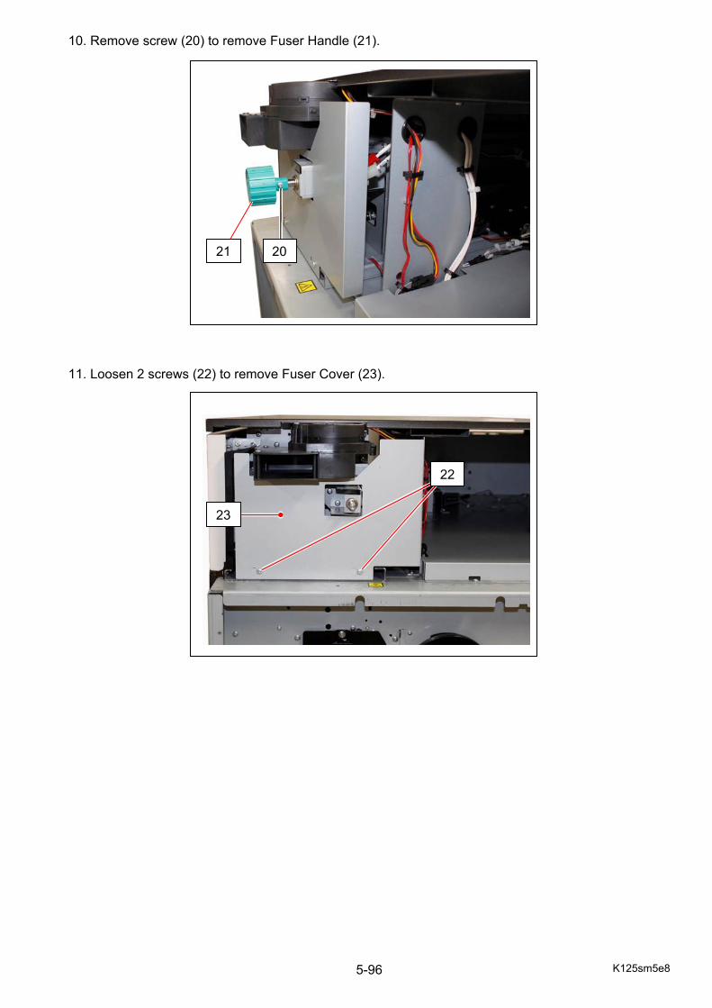
K125sm5e8 5-96
10. Remove screw (20) to remove Fuser Handle (21). 11. Loosen 2 screws (22) to remove Fuser Cover (23).
20 21
22
23
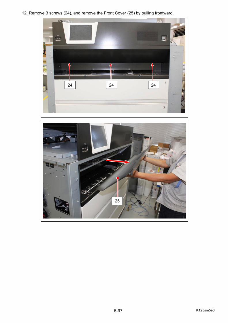
K125sm5e8 5-97
12. Remove 3 screws (24), and remove the Front Cover (25) by pulling frontward.
242424
25
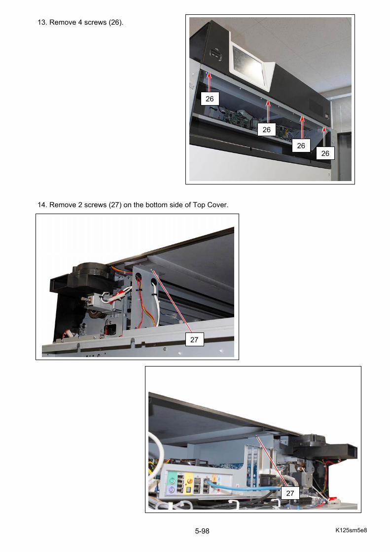
K125sm5e8 5-98
13. Remove 4 screws (26). 14. Remove 2 screws (27) on the bottom side of Top Cover.
26
26
26 26
27
27
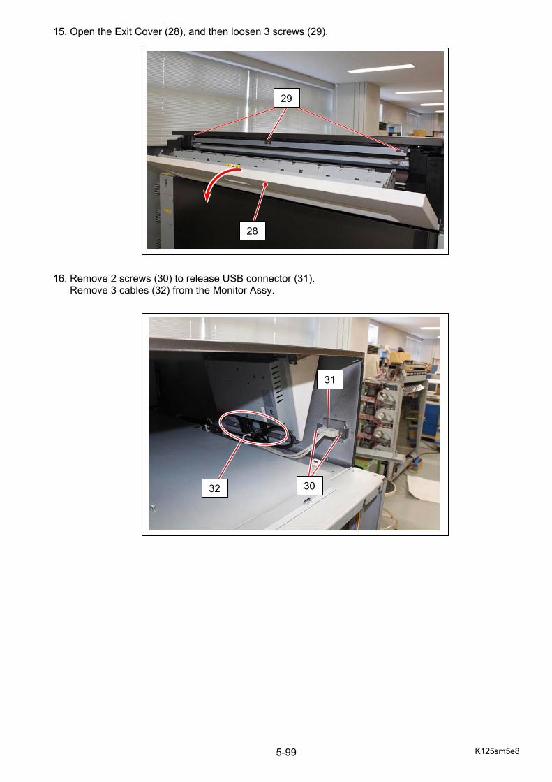
K125sm5e8 5-99
15. Open the Exit Cover (28), and then loosen 3 screws (29). 16. Remove 2 screws (30) to release USB connector (31). Remove 3 cables (32) from the Monitor Assy.
28
29
30
31
32
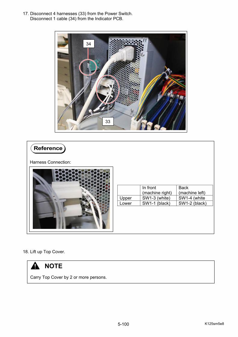
K125sm5e8 5-100
17. Disconnect 4 harnesses (33) from the Power Switch. Disconnect 1 cable (34) from the Indicator PCB. 18. Lift up Top Cover.
33
34
Reference
Harness Connection:
In front (machine right)
Back (machine left)
Upper SW1-3 (white) SW1-4 (white Lower SW1-1 (black) SW1-2 (black)
NOTE Carry Top Cover by 2 or more persons.
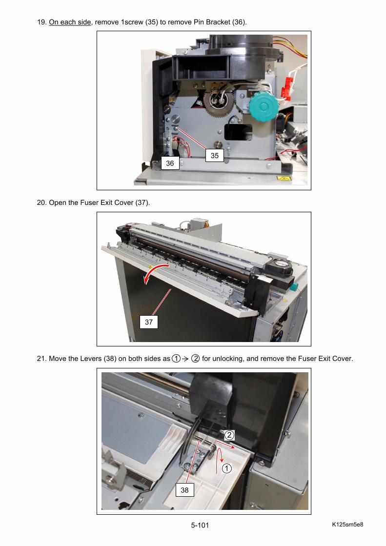
K125sm5e8 5-101
19. On each side, remove 1screw (35) to remove Pin Bracket (36). 20. Open the Fuser Exit Cover (37). 21. Move the Levers (38) on both sides as 1 2 for unlocking, and remove the Fuser Exit Cover.
3536
37
38
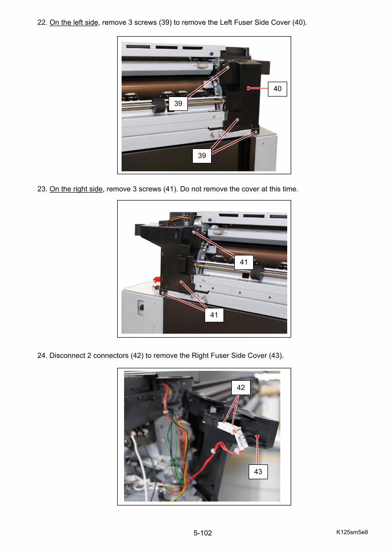
K125sm5e8 5-102
22. On the left side, remove 3 screws (39) to remove the Left Fuser Side Cover (40). 23. On the right side, remove 3 screws (41). Do not remove the cover at this time. 24. Disconnect 2 connectors (42) to remove the Right Fuser Side Cover (43).
39
39
40
41
41
43
42
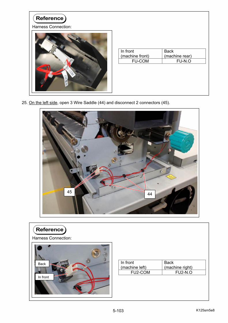
K125sm5e8 5-103
25. On the left side, open 3 Wire Saddle (44) and disconnect 2 connectors (45).
4445
Reference
Harness Connection:
In front (machine front)
Back (machine rear)
FU-COM FU-N.O
Reference
Harness Connection:
In front (machine left)
Back (machine right)
FU2-COM FU2-N.O
Back
In front
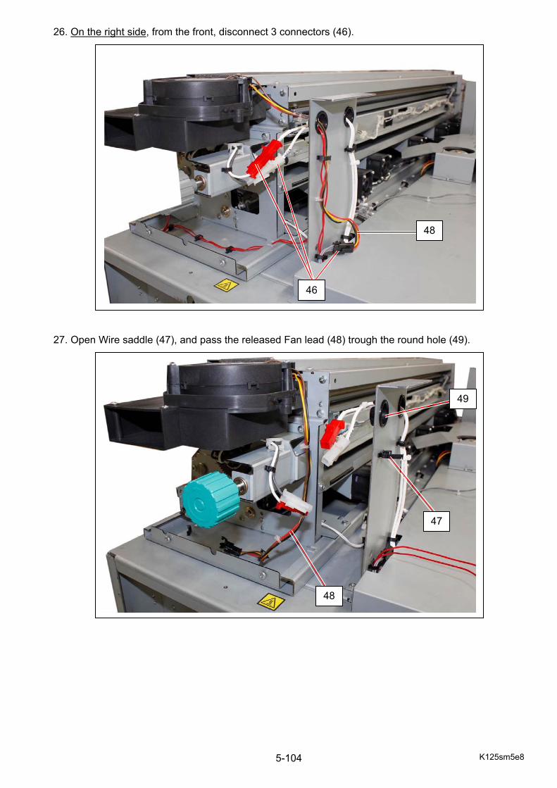
K125sm5e8 5-104
26. On the right side, from the front, disconnect 3 connectors (46). 27. Open Wire saddle (47), and pass the released Fan lead (48) trough the round hole (49).
46
48
47
48
49
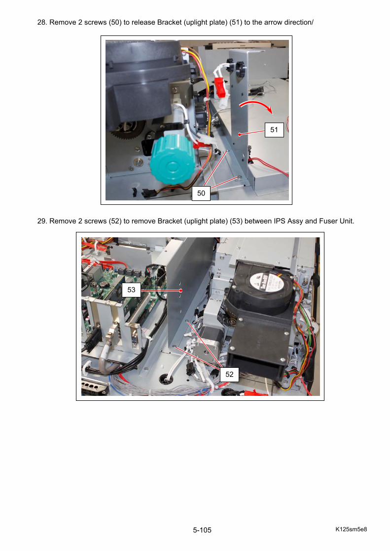
K125sm5e8 5-105
28. Remove 2 screws (50) to release Bracket (uplight plate) (51) to the arrow direction/ 29. Remove 2 screws (52) to remove Bracket (uplight plate) (53) between IPS Assy and Fuser Unit.
50
51
52
53
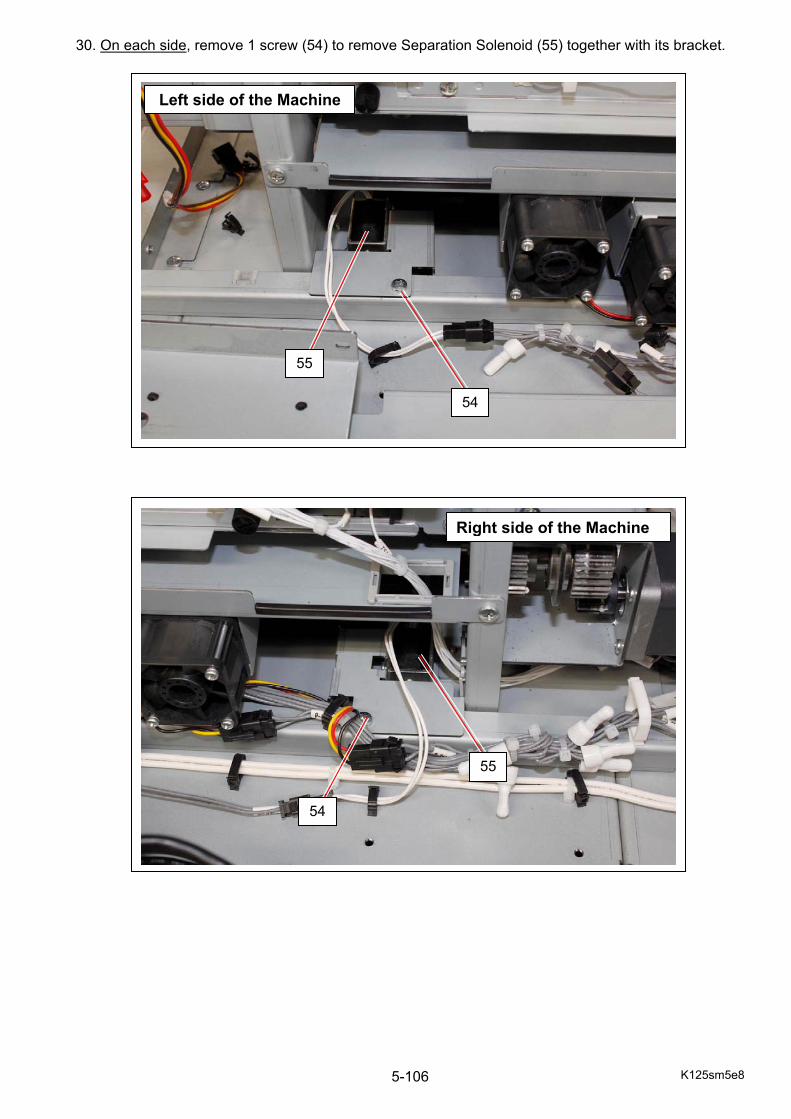
K125sm5e8 5-106
30. On each side, remove 1 screw (54) to remove Separation Solenoid (55) together with its bracket.
54
55
Left side of the Machine
54
55
Right side of the Machine

K125sm5e8 5-107
31. On the right side, disconnect all the harnesses from Fuser Unit. 32. Open the Rear Door.
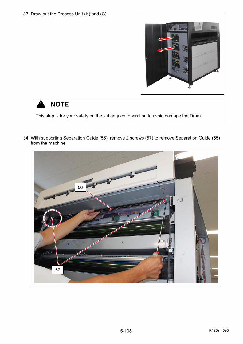
K125sm5e8 5-108
33. Draw out the Process Unit (K) and (C). 34. With supporting Separation Guide (56), remove 2 screws (57) to remove Separation Guide (55) from the machine.
NOTE This step is for your safety on the subsequent operation to avoid damage the Drum.
56
57
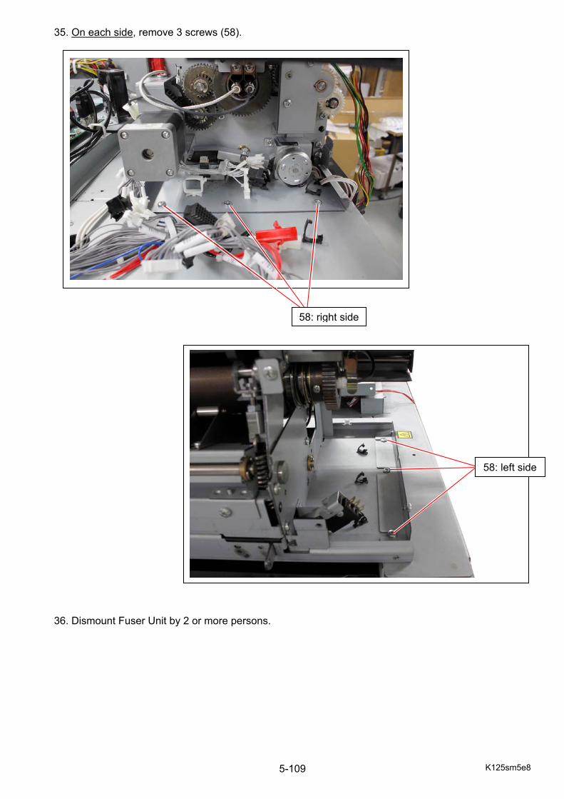
K125sm5e8 5-109
35. On each side, remove 3 screws (58). 36. Dismount Fuser Unit by 2 or more persons.
58: right side
58: left side
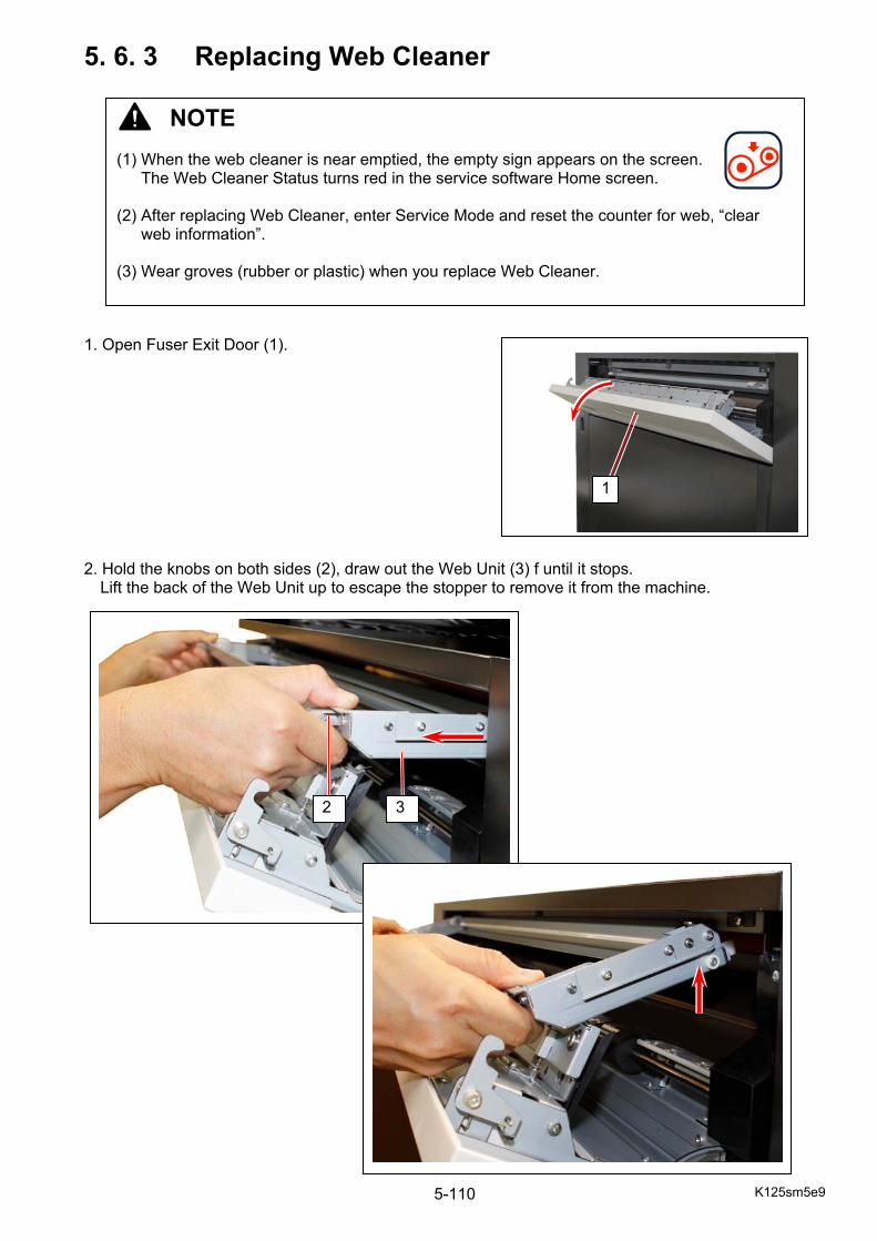
K125sm5e9 5-110
5. 6. 3 Replacing Web Cleaner
1. Open Fuser Exit Door (1).
2. Hold the knobs on both sides (2), draw out the Web Unit (3) f until it stops.
Lift the back of the Web Unit up to escape the stopper to remove it from the machine.
NOTE (1) When the web cleaner is near emptied, the empty sign appears on the screen.
The Web Cleaner Status turns red in the service software Home screen. (2) After replacing Web Cleaner, enter Service Mode and reset the counter for web, “clear
web information”.
(3) Wear groves (rubber or plastic) when you replace Web Cleaner.
1
3 2

K125sm5e9 5-111
4. Push both of the rolls of Web Cleaner (4) to the arrow direction (right hand side, machine left) to remove Web Cleaner (4). 5. Install the thicker roll of Web (5) to the shaft’s pin (6) on the back (inner) of your right hand side. Fit the pin (6) to the notch (7) on the core bar of the roll (5).
4
NOTE Install the Web in the correct direction noting its winding direction.
6
5
6
7
Knob
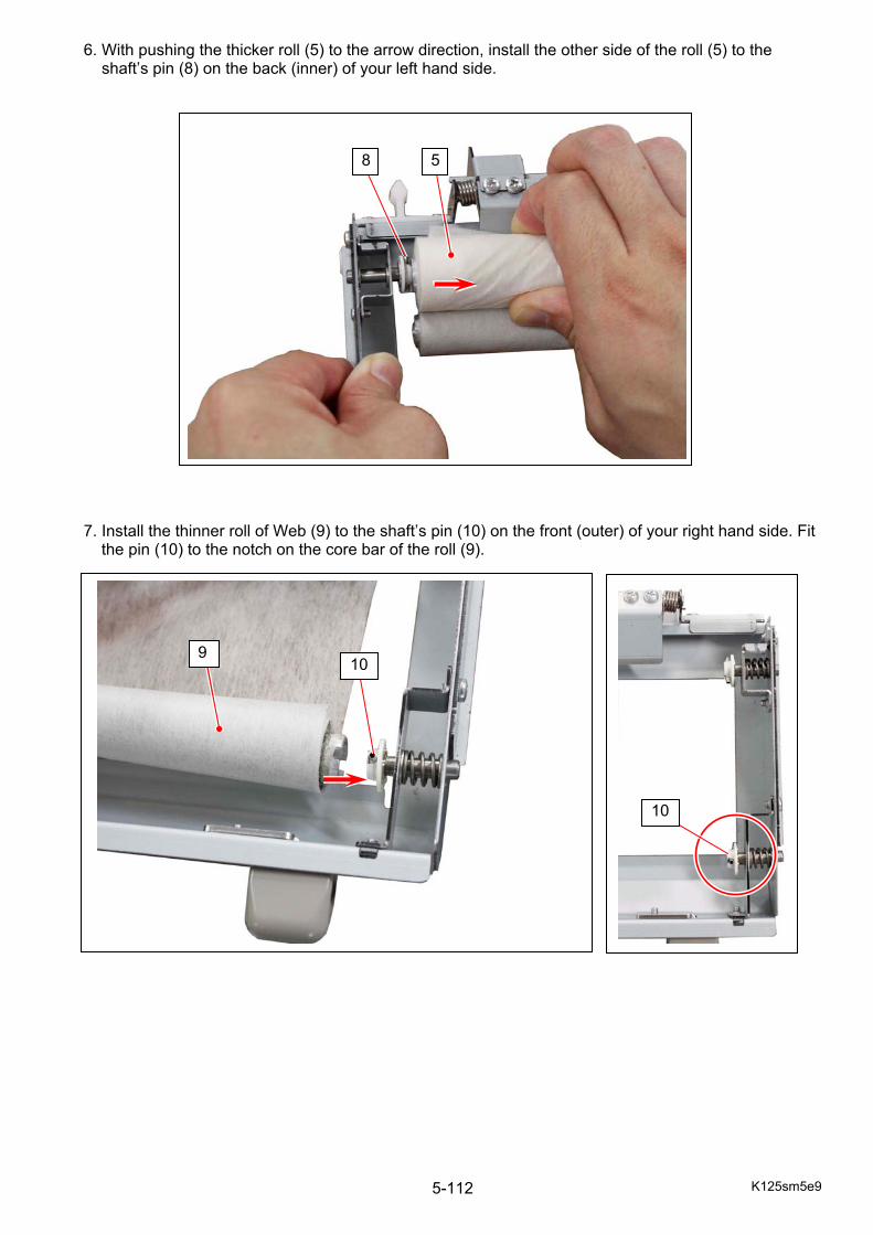
K125sm5e9 5-112
6. With pushing the thicker roll (5) to the arrow direction, install the other side of the roll (5) to the shaft’s pin (8) on the back (inner) of your left hand side. 7. Install the thinner roll of Web (9) to the shaft’s pin (10) on the front (outer) of your right hand side. Fit
the pin (10) to the notch on the core bar of the roll (9).
9
8 5
10
10
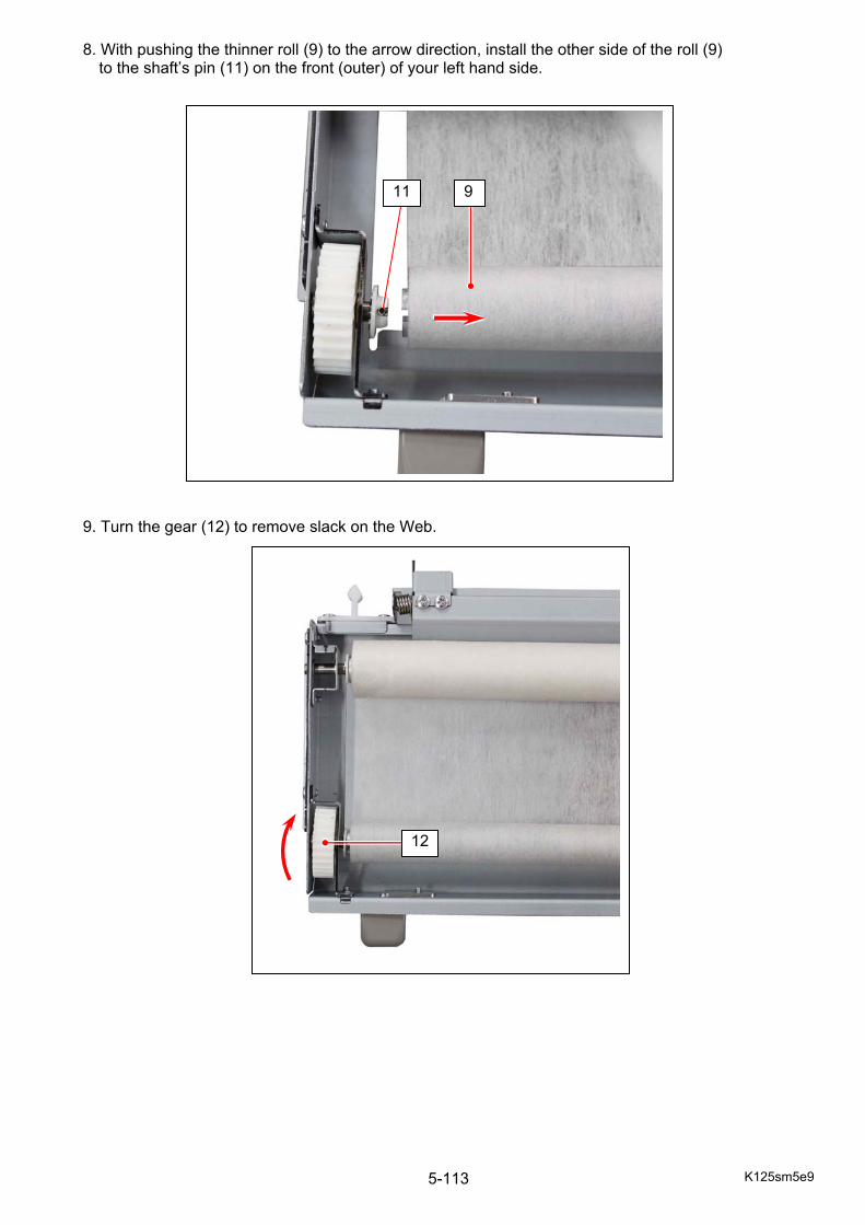
K125sm5e9 5-113
8. With pushing the thinner roll (9) to the arrow direction, install the other side of the roll (9) to the shaft’s pin (11) on the front (outer) of your left hand side. 9. Turn the gear (12) to remove slack on the Web.
12
11 9
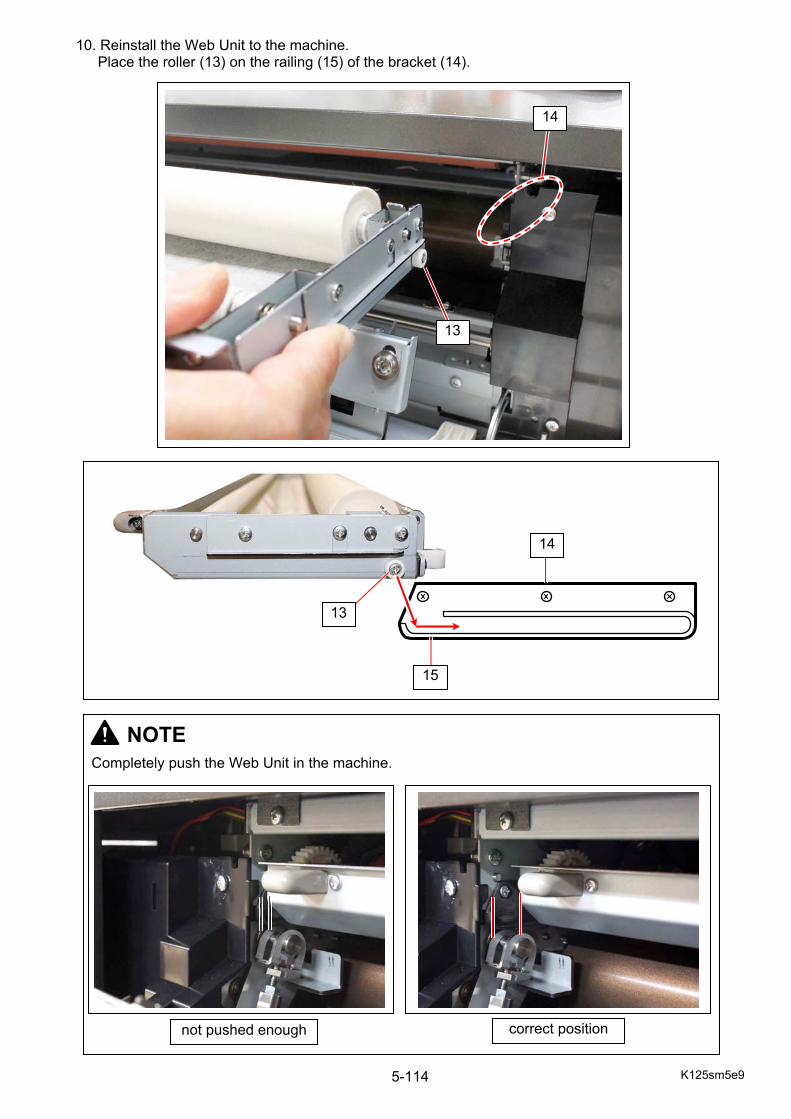
K125sm5e9 5-114
10. Reinstall the Web Unit to the machine. Place the roller (13) on the railing (15) of the bracket (14).
13
14
NOTE
Completely push the Web Unit in the machine.
not pushed enough correct position
15
14
13
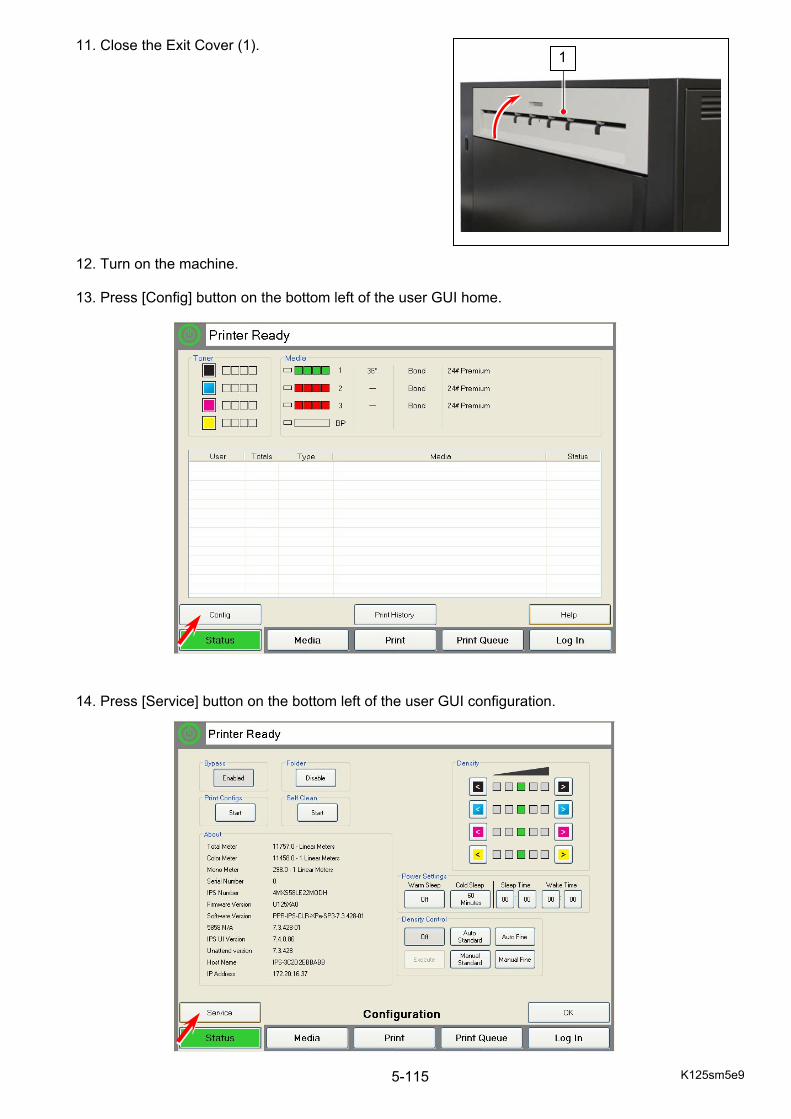
K125sm5e9 5-115
11. Close the Exit Cover (1). 12. Turn on the machine. 13. Press [Config] button on the bottom left of the user GUI home.
14. Press [Service] button on the bottom left of the user GUI configuration.
1
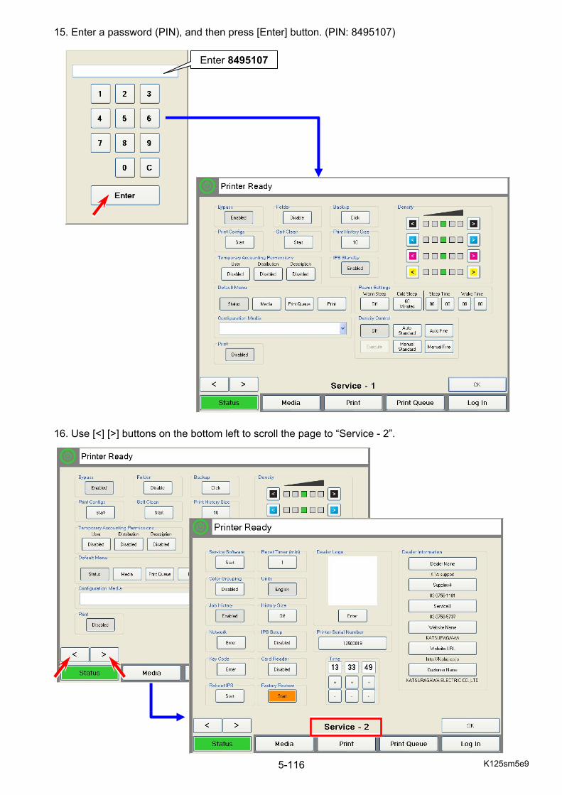
K125sm5e9 5-116
15. Enter a password (PIN), and then press [Enter] button. (PIN: 8495107)
16. Use [<] [>] buttons on the bottom left to scroll the page to “Service - 2”.
Enter 8495107
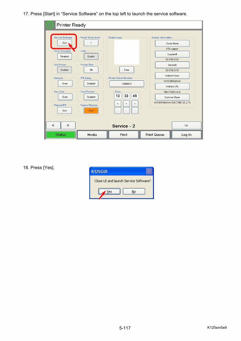
K125sm5e9 5-117
17. Press [Start] in “Service Software” on the top left to launch the service software. 18. Press [Yes].
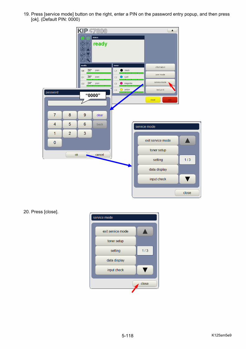
K125sm5e9 5-118
19. Press [service mode] button on the right, enter a PIN on the password entry popup, and then press [ok]. (Default PIN: 0000)
20. Press [close].
“0000”
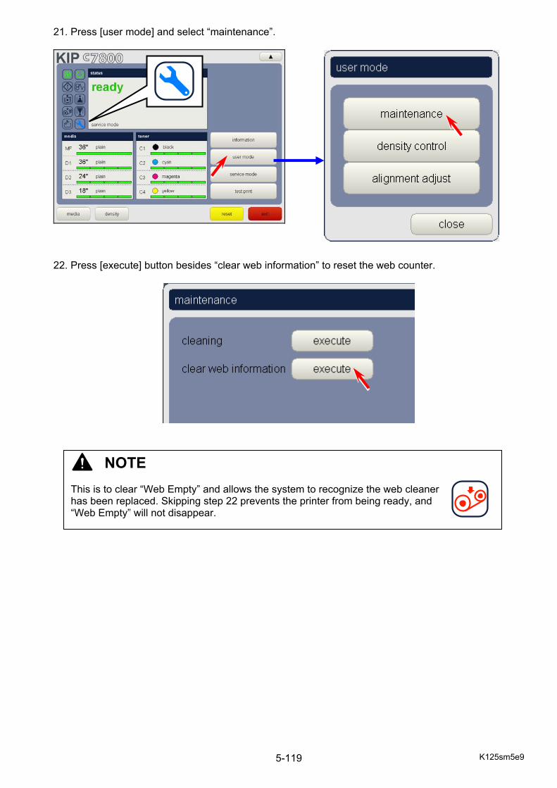
K125sm5e9 5-119
21. Press [user mode] and select “maintenance”.
22. Press [execute] button besides “clear web information” to reset the web counter.
NOTE This is to clear “Web Empty” and allows the system to recognize the web cleaner has been replaced. Skipping step 22 prevents the printer from being ready, and “Web Empty” will not disappear.
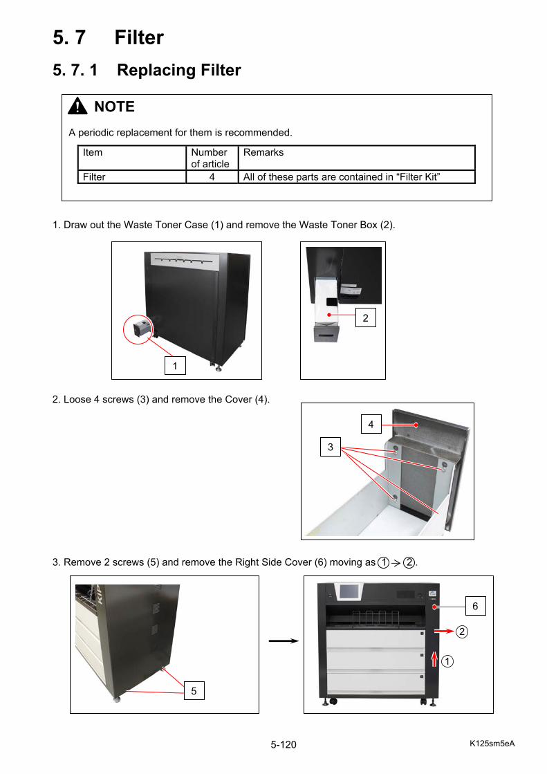
K125sm5eA 5-120
5. 7 Filter
5. 7. 1 Replacing Filter 1. Draw out the Waste Toner Case (1) and remove the Waste Toner Box (2). 2. Loose 4 screws (3) and remove the Cover (4). 3. Remove 2 screws (5) and remove the Right Side Cover (6) moving as 1 2 .
5
4
3
1
2
NOTE A periodic replacement for them is recommended.
Item Number of article
Remarks
Filter 4 All of these parts are contained in “Filter Kit”
6
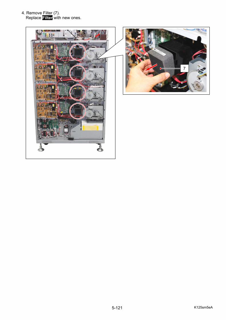
K125sm5eA 5-121
4. Remove Filter (7). Replace Filter with new ones.
7

K125sm5eB 5-122
5. 8 Belt Unit
5. 8. 1 Replacing BC Blade 1. Open the Rear Door (1). 2. Remove 2 door stopper screws (2) and fully open the Rear Door (1).
1
NOTE A periodic replacement for them is recommended.
Item Number of article
Remarks
BC Blade 1 Belt Cleaner Blade
1
2
2
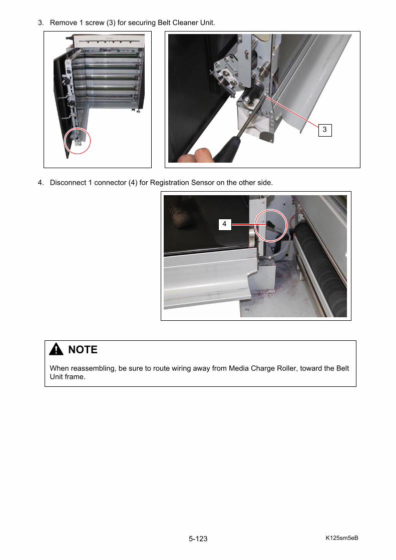
K125sm5eB 5-123
3. Remove 1 screw (3) for securing Belt Cleaner Unit. 4. Disconnect 1 connector (4) for Registration Sensor on the other side.
3
4
NOTE When reassembling, be sure to route wiring away from Media Charge Roller, toward the Belt Unit frame.
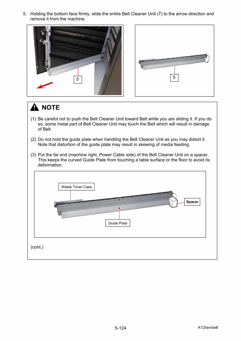
K125sm5eB 5-124
5. Holding the bottom face firmly, slide the entire Belt Cleaner Unit (7) to the arrow direction and remove it from the machine.
5
NOTE (1) Be careful not to push the Belt Cleaner Unit toward Belt while you are sliding it. If you do
so, some metal part of Belt Cleaner Unit may touch the Belt which will result in damage of Belt.
(2) Do not hold the guide plate when handling the Belt Cleaner Unit as you may distort it.
Note that distortion of the guide plate may result in skewing of media feeding. (3) Put the far end (machine right, Power Cable side) of the Belt Cleaner Unit on a spacer.
This keeps the curved Guide Plate from touching a table surface or the floor to avoid its deformation.
(cont.)
5
Waste Toner Case
Guide Plate
Spacer

K125sm5eB 5-125
NOTE (cont.) (4) When returning the Belt Cleaner Unit to the machine, be sure to fit the positioning pins
into the positioning holes. (Another side of the unit has 2 positioning pins as well.)
Positioning Hole
Positioning Pin
Near End (machine left) Belt Cleaner Unit: Hole Belt Unit: Pin
Far End (machine right) Belt Cleaner Unit: Pin Belt Unit: Hole
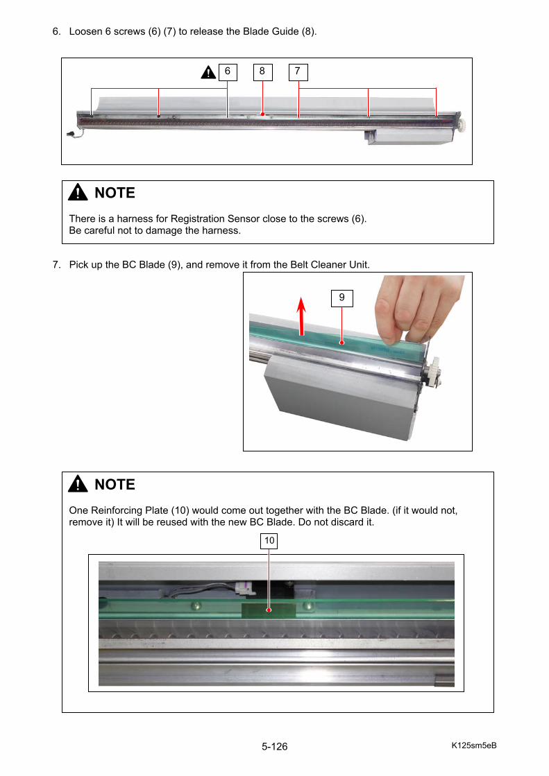
K125sm5eB 5-126
6. Loosen 6 screws (6) (7) to release the Blade Guide (8). 7. Pick up the BC Blade (9), and remove it from the Belt Cleaner Unit.
6 78
NOTE There is a harness for Registration Sensor close to the screws (6). Be careful not to damage the harness.
9
NOTE One Reinforcing Plate (10) would come out together with the BC Blade. (if it would not, remove it) It will be reused with the new BC Blade. Do not discard it.
10
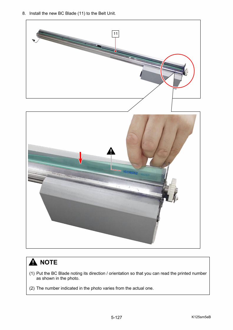
K125sm5eB 5-127
8. Install the new BC Blade (11) to the Belt Unit.
11
NOTE (1) Put the BC Blade noting its direction / orientation so that you can read the printed number
as shown in the photo. (2) The number indicated in the photo varies from the actual one.
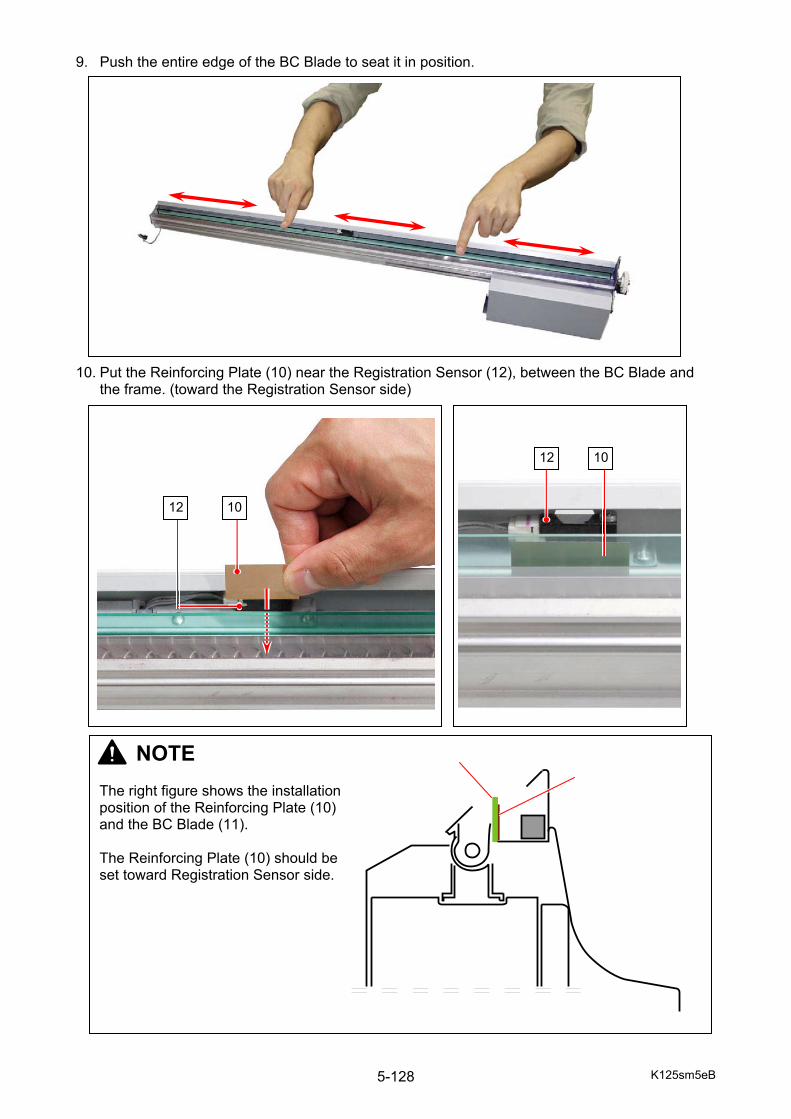
K125sm5eB 5-128
9. Push the entire edge of the BC Blade to seat it in position. 10. Put the Reinforcing Plate (10) near the Registration Sensor (12), between the BC Blade and
the frame. (toward the Registration Sensor side)
NOTE The right figure shows the installation position of the Reinforcing Plate (10) and the BC Blade (11). The Reinforcing Plate (10) should be set toward Registration Sensor side.
12 10
10 12
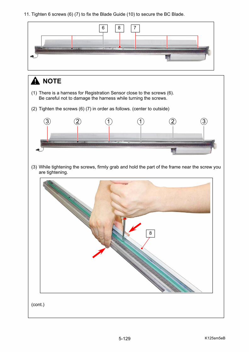
K125sm5eB 5-129
11. Tighten 6 screws (6) (7) to fix the Blade Guide (10) to secure the BC Blade.
6 78
NOTE (1) There is a harness for Registration Sensor close to the screws (6).
Be careful not to damage the harness while turning the screws. (2) Tighten the screws (6) (7) in order as follows. (center to outside) (3) While tightening the screws, firmly grab and hold the part of the frame near the screw you
are tightening. (cont.)
8
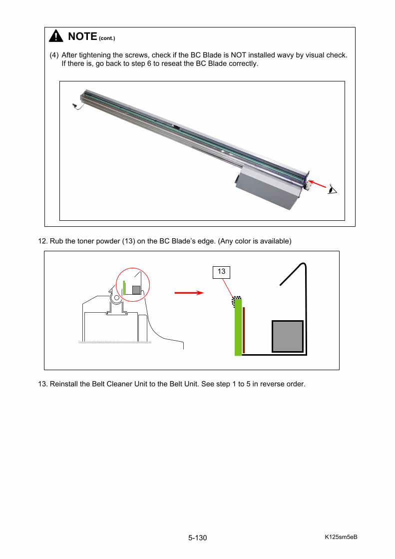
K125sm5eB 5-130
12. Rub the toner powder (13) on the BC Blade’s edge. (Any color is available) 13. Reinstall the Belt Cleaner Unit to the Belt Unit. See step 1 to 5 in reverse order.
NOTE (cont.) (4) After tightening the screws, check if the BC Blade is NOT installed wavy by visual check.
If there is, go back to step 6 to reseat the BC Blade correctly.
13
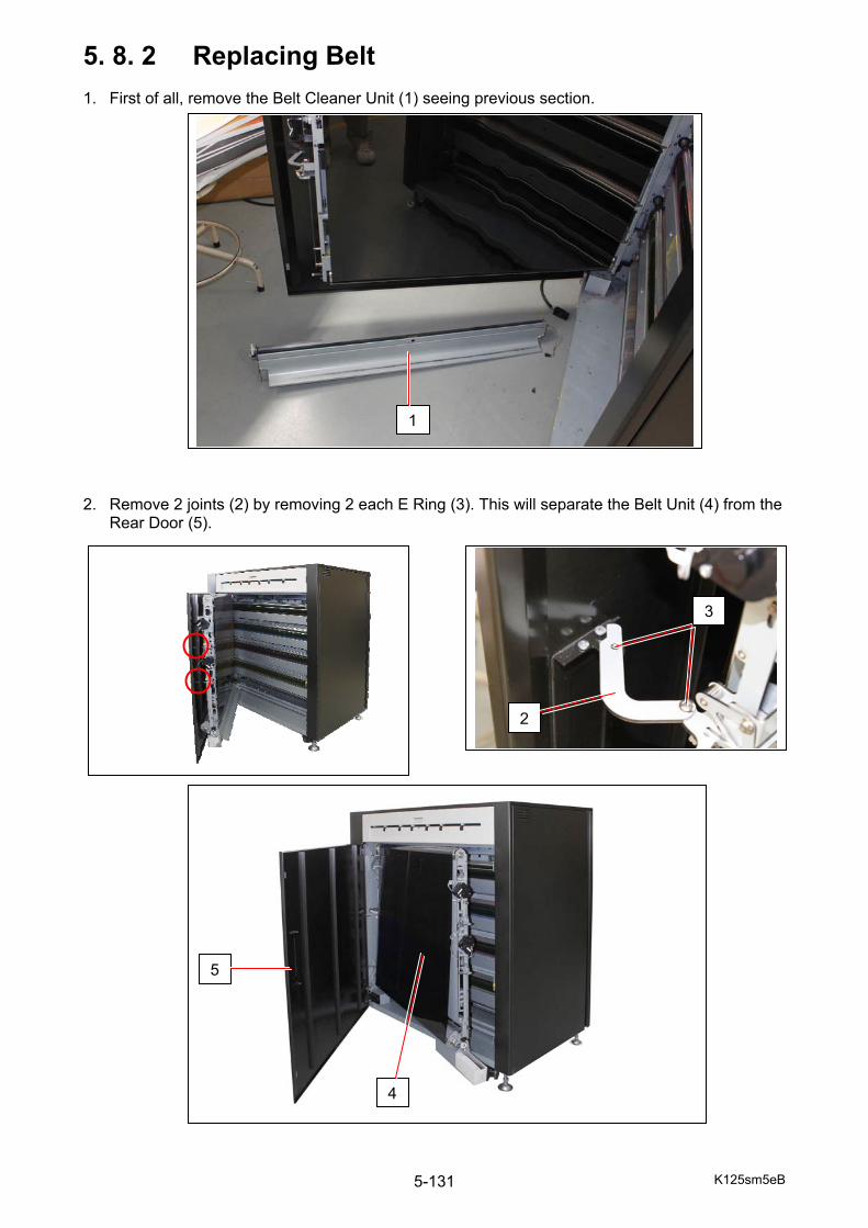
K125sm5eB 5-131
5. 8. 2 Replacing Belt 1. First of all, remove the Belt Cleaner Unit (1) seeing previous section. 2. Remove 2 joints (2) by removing 2 each E Ring (3). This will separate the Belt Unit (4) from the
Rear Door (5).
1
3
2
5
4
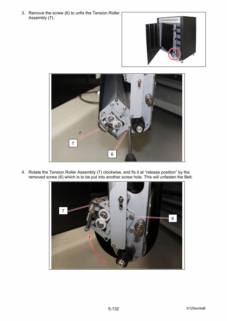
K125sm5eB 5-132
3. Remove the screw (6) to unfix the Tension Roller Assembly (7).
4. Rotate the Tension Roller Assembly (7) clockwise, and fix it at “release position” by the
removed screw (6) which is to be put into another screw hole. This will unfasten the Belt.
6
7
6
7
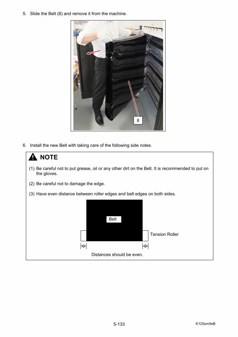
K125sm5eB 5-133
5. Slide the Belt (8) and remove it from the machine. 6. Install the new Belt with taking care of the following side notes.
8
NOTE (1) Be careful not to put grease, oil or any other dirt on the Belt. It is recommended to put on
the gloves. (2) Be careful not to damage the edge. (3) Have even distance between roller edges and belt edges on both sides. Tension Roller Distances should be even.
Belt
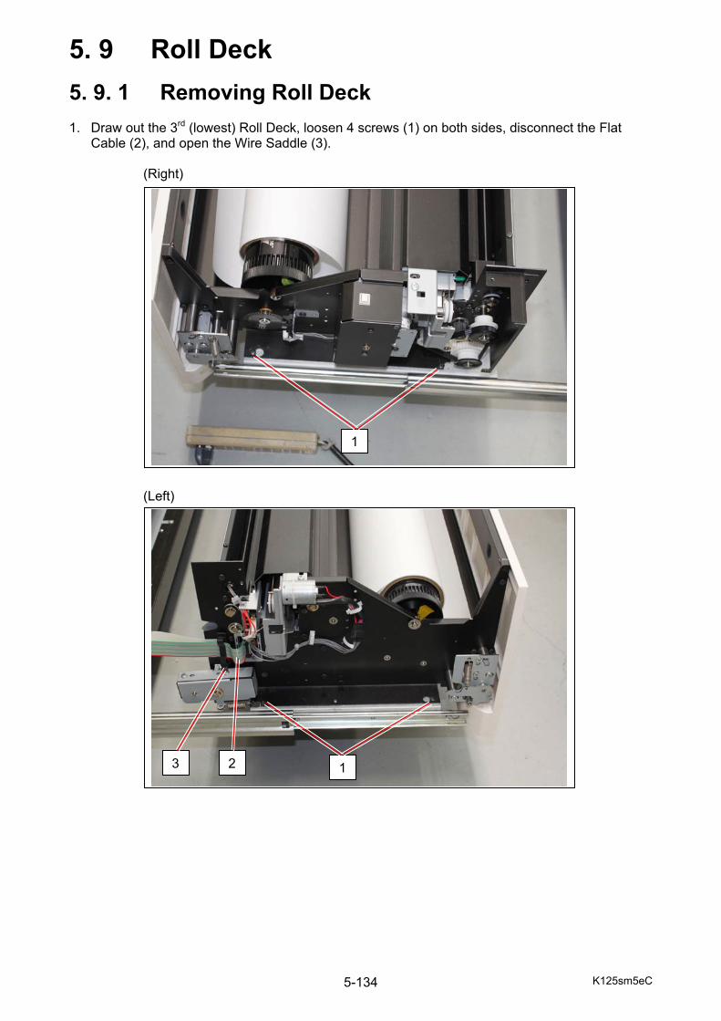
K125sm5eC 5-134
5. 9 Roll Deck
5. 9. 1 Removing Roll Deck 1. Draw out the 3rd (lowest) Roll Deck, loosen 4 screws (1) on both sides, disconnect the Flat
Cable (2), and open the Wire Saddle (3). (Right) (Left)
1
13 2

K125sm5eC 5-135
2. Remove the Wire Saddle (3), and then remove the entire 3rd Roll Deck (4) from the slide rails.
3 4
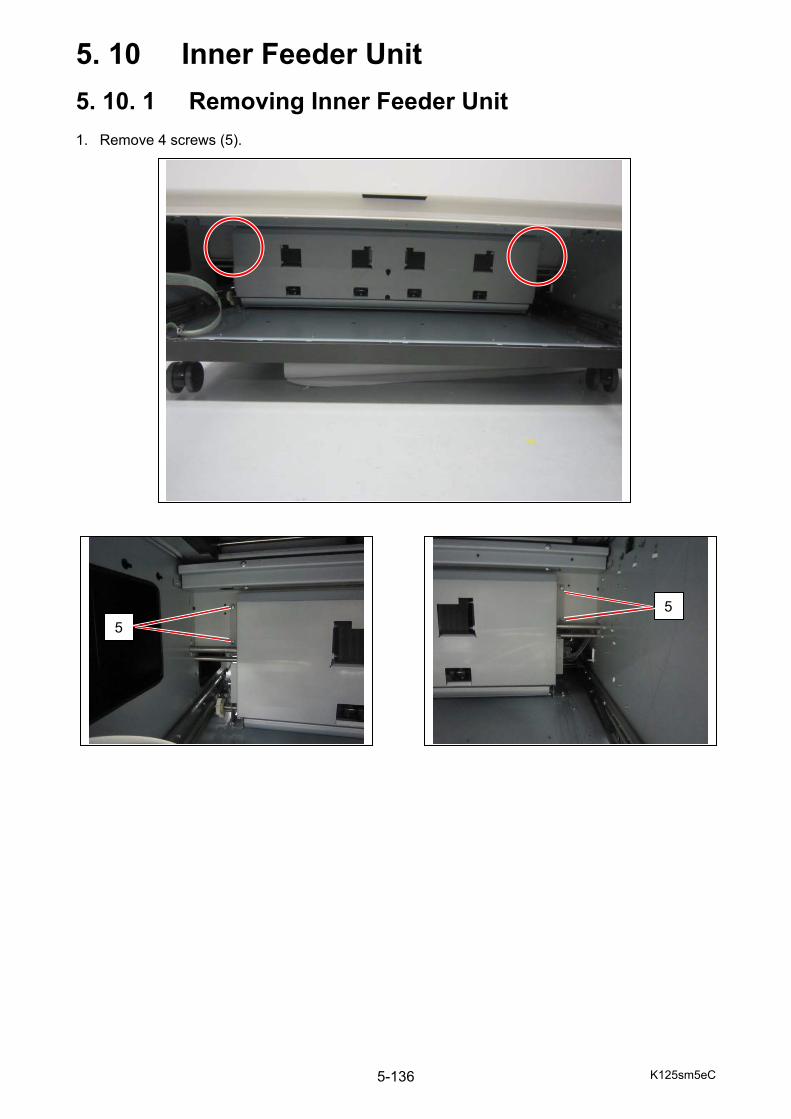
K125sm5eC 5-136
5. 10 Inner Feeder Unit
5. 10. 1 Removing Inner Feeder Unit 1. Remove 4 screws (5).
5 5
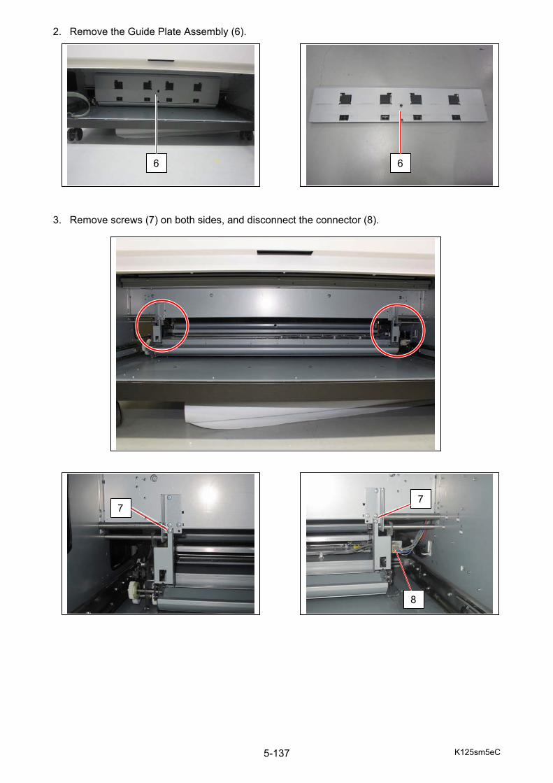
K125sm5eC 5-137
2. Remove the Guide Plate Assembly (6). 3. Remove screws (7) on both sides, and disconnect the connector (8).
6 6
7 7
8

K125sm5eC 5-138
4. Open the Left Side Door, remove 3 screws (9), and remove the harness cover (10). 5. Disconnect the connector (11).
9
10
11
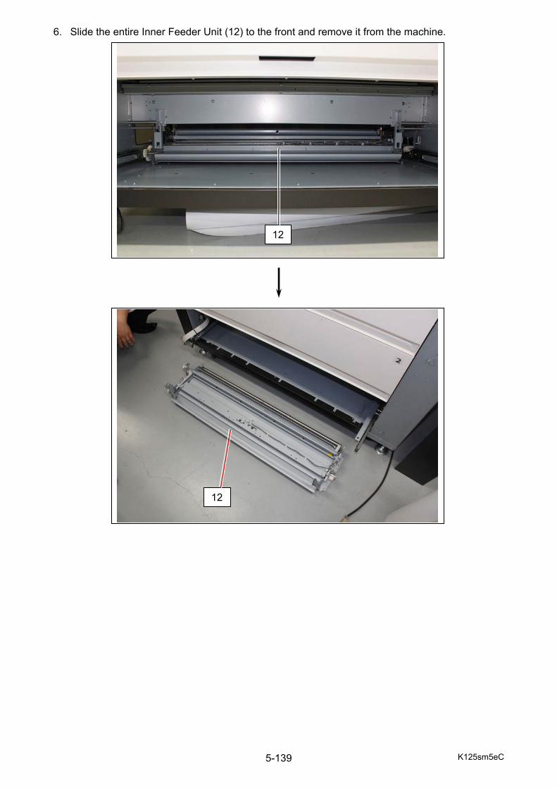
K125sm5eC 5-139
6. Slide the entire Inner Feeder Unit (12) to the front and remove it from the machine.
12
12

K125sm5eD 5-140
5. 11 Cutter Unit
5. 11. 1 Removing Cutter Unit 1. Draw out the Roll Deck (1). 2. Open Cutter Cover (2).
1
NOTE
Every Roll Deck drawer is equipped with the Cutter Unit.
2
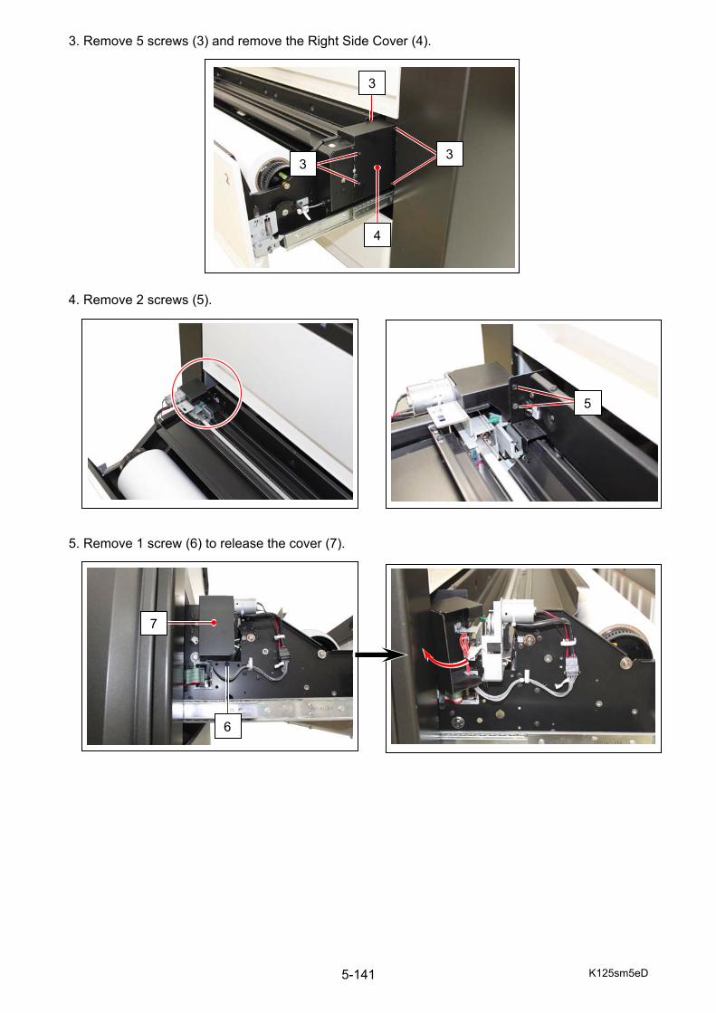
K125sm5eD 5-141
3. Remove 5 screws (3) and remove the Right Side Cover (4). 4. Remove 2 screws (5). 5. Remove 1 screw (6) to release the cover (7).
33
3
4
5
6
7
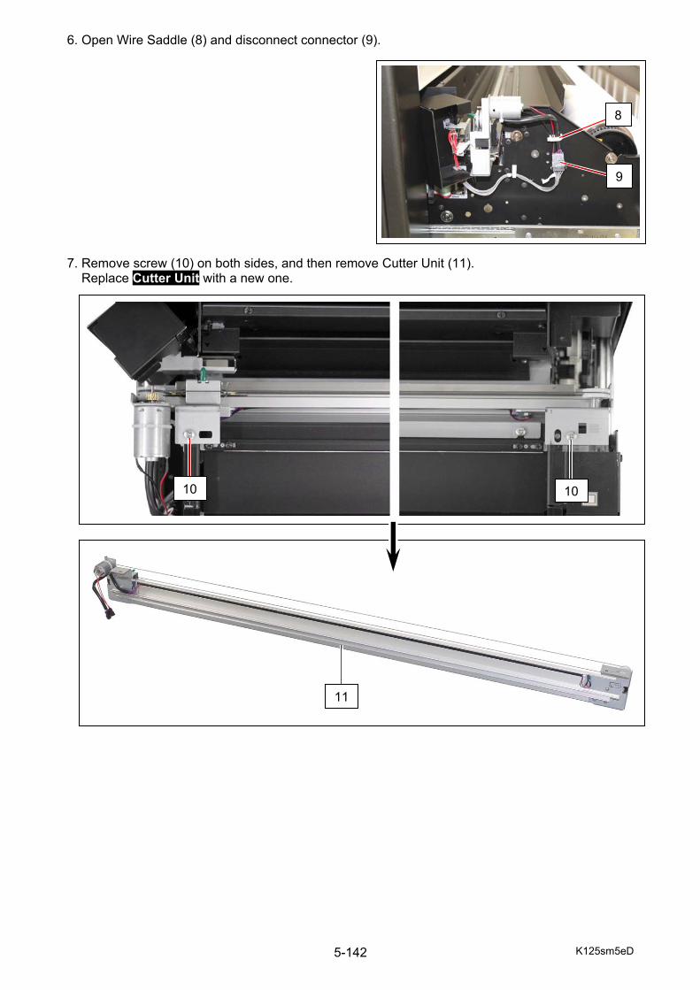
K125sm5eD 5-142
6. Open Wire Saddle (8) and disconnect connector (9). 7. Remove screw (10) on both sides, and then remove Cutter Unit (11). Replace Cutter Unit with a new one.
8
9
10
11
10
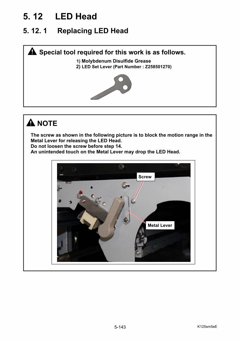
K125sm5eE 5-143
5. 12 LED Head
5. 12. 1 Replacing LED Head
NOTE
The screw as shown in the following picture is to block the motion range in the Metal Lever for releasing the LED Head. Do not loosen the screw before step 14. An unintended touch on the Metal Lever may drop the LED Head.
Screw
Metal Lever
Special tool required for this work is as follows.
1) Molybdenum Disulfide Grease 2) LED Set Lever (Part Number : Z258501270)
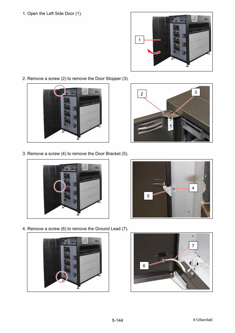
K125sm5eE 5-144
1. Open the Left Side Door (1). 2. Remove a screw (2) to remove the Door Stopper (3). 3. Remove a screw (4) to remove the Door Bracket (5). 4. Remove a screw (6) to remove the Ground Lead (7).
1
2 3
4
5
6
7
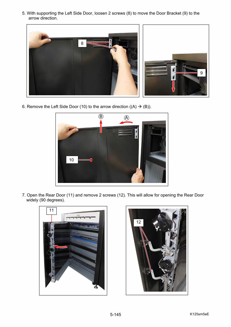
K125sm5eE 5-145
5. With supporting the Left Side Door, loosen 2 screws (8) to move the Door Bracket (9) to the arrow direction.
6. Remove the Left Side Door (10) to the arrow direction ((A) (B)). 7. Open the Rear Door (11) and remove 2 screws (12). This will allow for opening the Rear Door
widely (90 degrees).
10
8
9
11
12
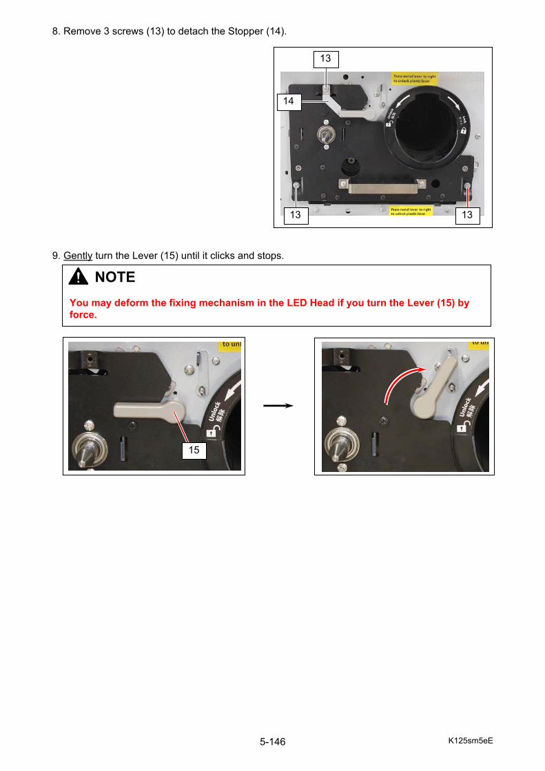
K125sm5eE 5-146
8. Remove 3 screws (13) to detach the Stopper (14).
9. Gently turn the Lever (15) until it clicks and stops.
15
13
13 13
14
NOTE You may deform the fixing mechanism in the LED Head if you turn the Lever (15) by force.
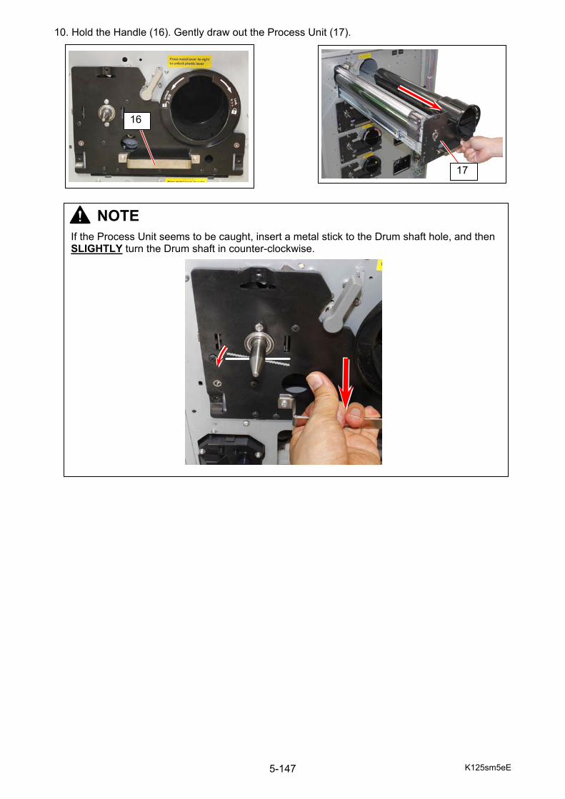
K125sm5eE 5-147
10. Hold the Handle (16). Gently draw out the Process Unit (17).
16
17
NOTE
If the Process Unit seems to be caught, insert a metal stick to the Drum shaft hole, and then SLIGHTLY turn the Drum shaft in counter-clockwise.
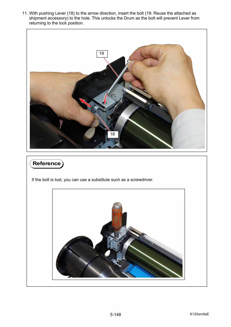
K125sm5eE 5-148
11. With pushing Lever (18) to the arrow direction, insert the bolt (19: Reuse the attached as shipment accessory) to the hole. This unlocks the Drum as the bolt will prevent Lever from returning to the lock position.
If the bolt is lost, you can use a substitute such as a screwdriver.
Reference
18
19
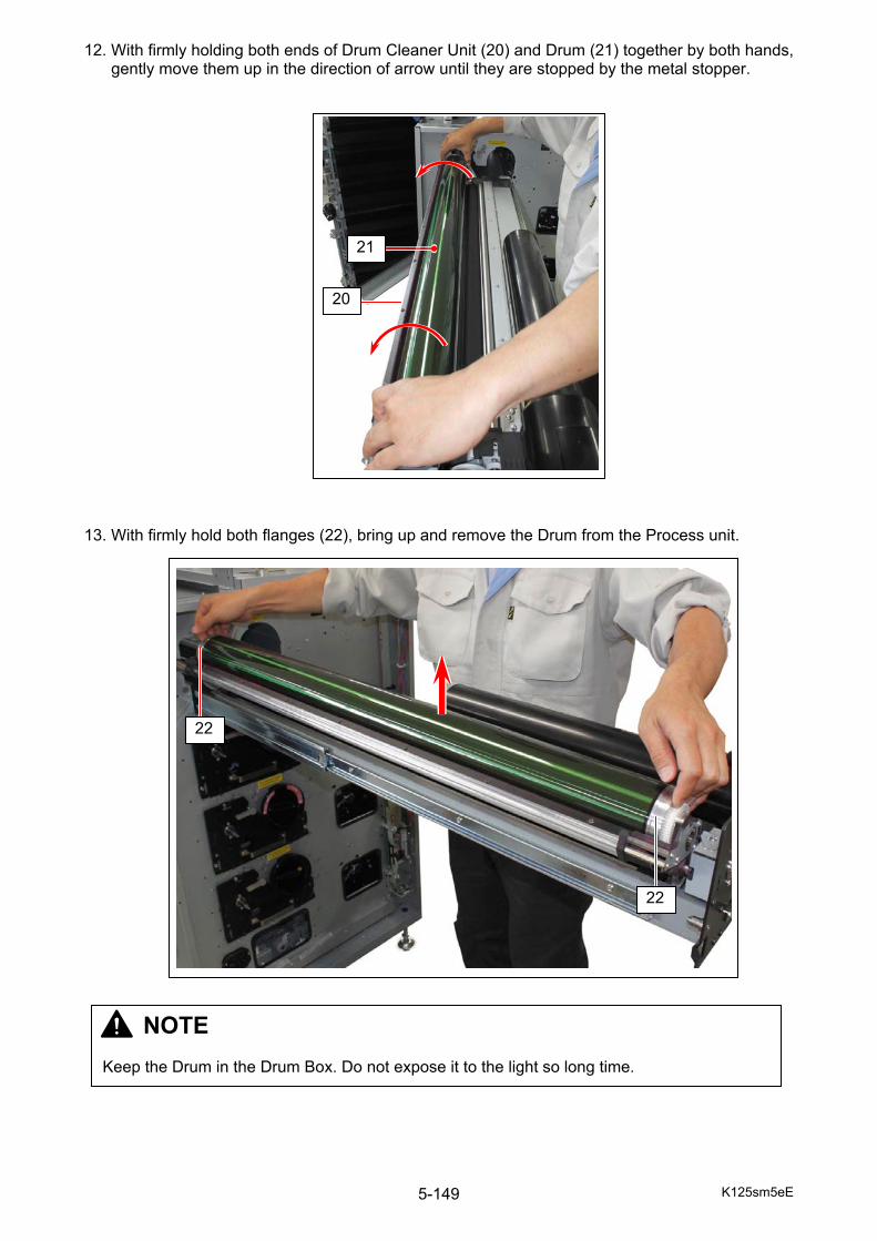
K125sm5eE 5-149
12. With firmly holding both ends of Drum Cleaner Unit (20) and Drum (21) together by both hands, gently move them up in the direction of arrow until they are stopped by the metal stopper. 13. With firmly hold both flanges (22), bring up and remove the Drum from the Process unit.
22
22
NOTE Keep the Drum in the Drum Box. Do not expose it to the light so long time.
20
21

K125sm5eE 5-150
14. Remove a screw (23). This screw (23) is just put in the hole and does not fix anything. It blocks and limits the Metal Lever’s (24) motion of range.
Surely hold the bottom of LED Head with left hand so as not to drop and damage it. Then press and hold the metal lever (24) toward arrow (A) and turn the lever (15) fully to arrow (B). This will unlock the LED Head. Place the LED Head inside the machine temporarily.
24
23
24
15 24
A
B
B
15
NOTE You may deform the fixing mechanism in the LED Head... - if you turn the Lever (15) by force without pressing the Metal Lever (24). - if you press the Metal Lever (24) by force.
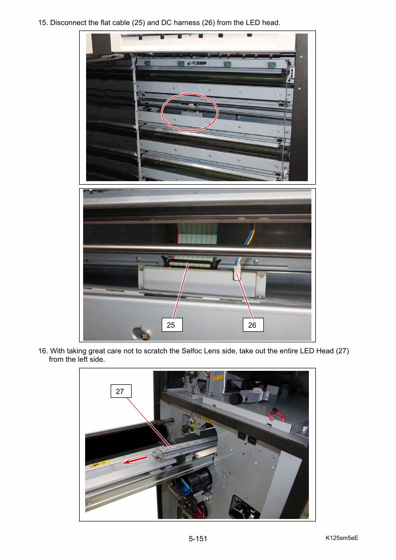
K125sm5eE 5-151
15. Disconnect the flat cable (25) and DC harness (26) from the LED head. 16. With taking great care not to scratch the Selfoc Lens side, take out the entire LED Head (27)
from the left side.
25 26
27
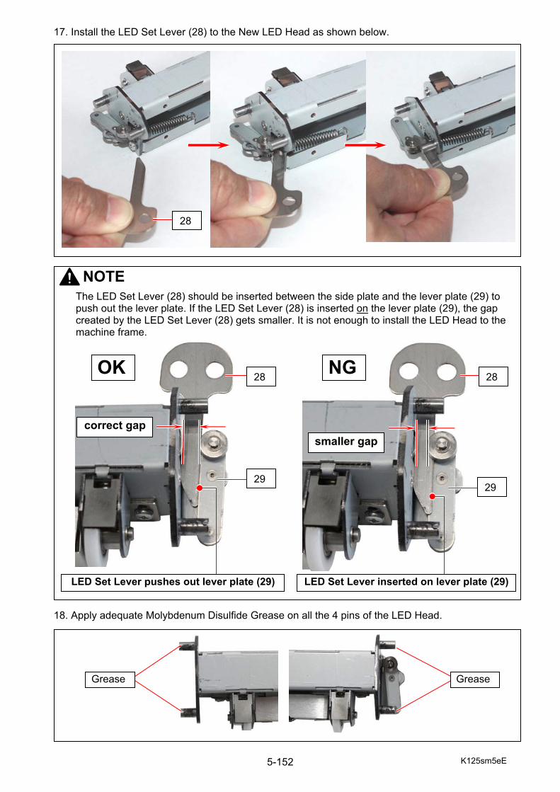
K125sm5eE 5-152
17. Install the LED Set Lever (28) to the New LED Head as shown below. 18. Apply adequate Molybdenum Disulfide Grease on all the 4 pins of the LED Head.
NOTE
The LED Set Lever (28) should be inserted between the side plate and the lever plate (29) to push out the lever plate. If the LED Set Lever (28) is inserted on the lever plate (29), the gap created by the LED Set Lever (28) gets smaller. It is not enough to install the LED Head to the machine frame.
correct gap
OK
29
LED Set Lever pushes out lever plate (29)
smaller gap
NG
29
28 28
28
LED Set Lever inserted on lever plate (29)
GreaseGrease
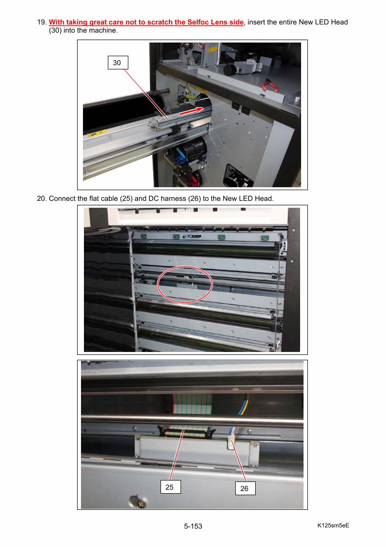
K125sm5eE 5-153
19. With taking great care not to scratch the Selfoc Lens side, insert the entire New LED Head (30) into the machine.
20. Connect the flat cable (25) and DC harness (26) to the New LED Head.
30
25 26

K125sm5eE 5-154
21. Follow the instruction below to bring up and support the LED Head. 21-1) Put your right hand in the machine from under the Drum Shaft (31).
Pick the top area as shown in the following picture to lift the LED Head. 21-2) Put your left hand in the machine from under the Drum Shaft.
Support the bottom of the LED Head on your left hand to bring it up. 21-3) With supporting by your left hand, support the bottom of the LED Head on your right hand.
31
Pick up here.
NOTE
Be careful not to attach grease from the Drum Shaft etc to the Selfoc Lens. If there is grease on the Selfoc Lens, completely remove grease from the Selfoc Lens with a soft cloth, and then wipe it with a soft cloth and alcohol.
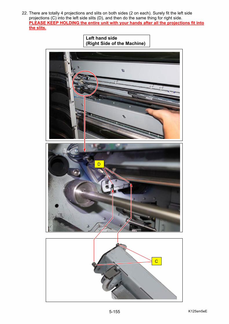
K125sm5eE 5-155
22. There are totally 4 projections and slits on both sides (2 on each). Surely fit the left side projections (C) into the left side slits (D), and then do the same thing for right side. PLEASE KEEP HOLDING the entire unit with your hands after all the projections fit into the slits.
D
Left hand side (Right Side of the Machine)
C

K125sm5eE 5-156
E
Right hand side (Left Side of the Machine)
NOTE
The plate (E) will be caught between the 2 metal small rollers.
D
C
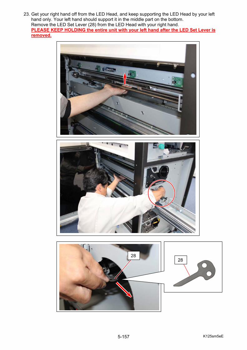
K125sm5eE 5-157
23. Get your right hand off from the LED Head, and keep supporting the LED Head by your left hand only. Your left hand should support it in the middle part on the bottom. Remove the LED Set Lever (28) from the LED Head with your right hand. PLEASE KEEP HOLDING the entire unit with your left hand after the LED Set Lever is removed.
28
28
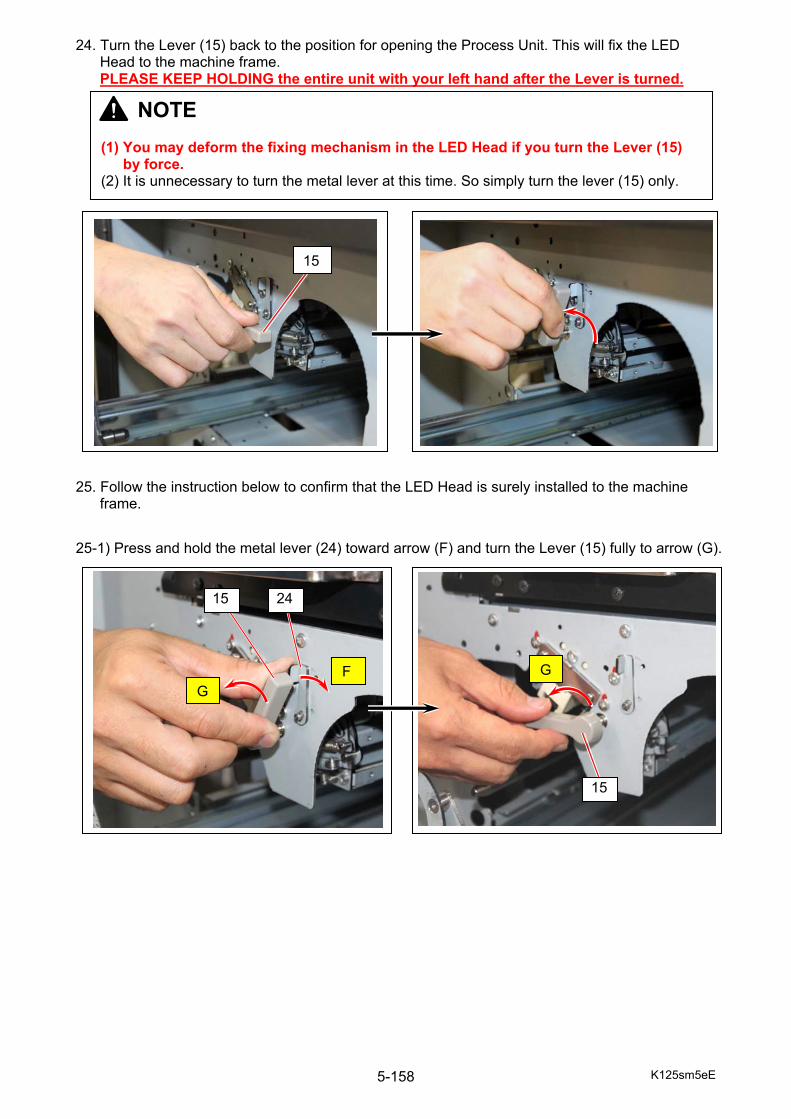
K125sm5eE 5-158
24. Turn the Lever (15) back to the position for opening the Process Unit. This will fix the LED Head to the machine frame. PLEASE KEEP HOLDING the entire unit with your left hand after the Lever is turned.
25. Follow the instruction below to confirm that the LED Head is surely installed to the machine
frame.
25-1) Press and hold the metal lever (24) toward arrow (F) and turn the Lever (15) fully to arrow (G).
15
24 15
15
FG
G
NOTE (1) You may deform the fixing mechanism in the LED Head if you turn the Lever (15)
by force. (2) It is unnecessary to turn the metal lever at this time. So simply turn the lever (15) only.
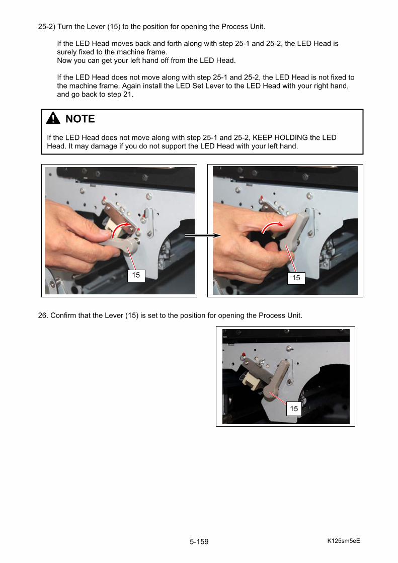
K125sm5eE 5-159
25-2) Turn the Lever (15) to the position for opening the Process Unit.
If the LED Head moves back and forth along with step 25-1 and 25-2, the LED Head is surely fixed to the machine frame. Now you can get your left hand off from the LED Head. If the LED Head does not move along with step 25-1 and 25-2, the LED Head is not fixed to the machine frame. Again install the LED Set Lever to the LED Head with your right hand, and go back to step 21.
26. Confirm that the Lever (15) is set to the position for opening the Process Unit.
15 15
15
NOTE If the LED Head does not move along with step 25-1 and 25-2, KEEP HOLDING the LED Head. It may damage if you do not support the LED Head with your left hand.
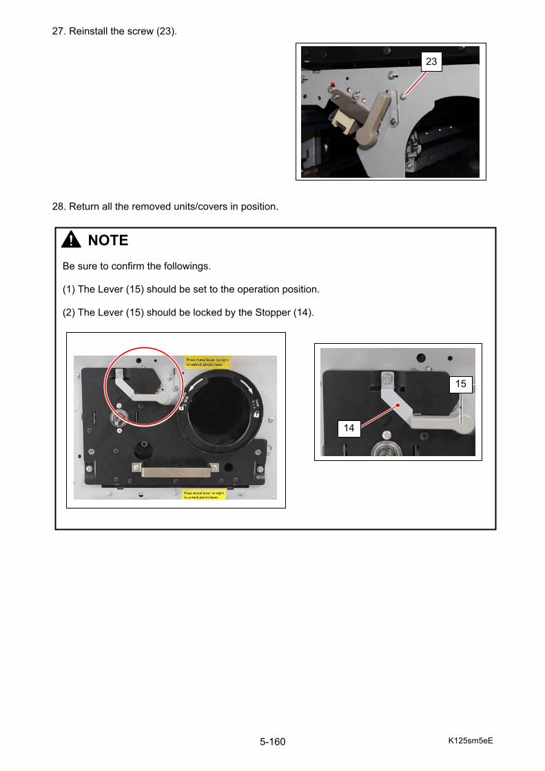
K125sm5eE 5-160
27. Reinstall the screw (23). 28. Return all the removed units/covers in position.
23
NOTE Be sure to confirm the followings. (1) The Lever (15) should be set to the operation position. (2) The Lever (15) should be locked by the Stopper (14).
14
15
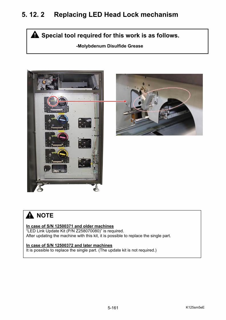
K125sm5eE 5-161
5. 12. 2 Replacing LED Head Lock mechanism
NOTE In case of S/N 12500371 and older machines “LED Link Update Kit (P/N Z258070080)” is required. After updating the machine with this kit, it is possible to replace the single part. In case of S/N 12500372 and later machines It is possible to replace the single part. (The update kit is not required.)
Special tool required for this work is as follows.
-Molybdenum Disulfide Grease
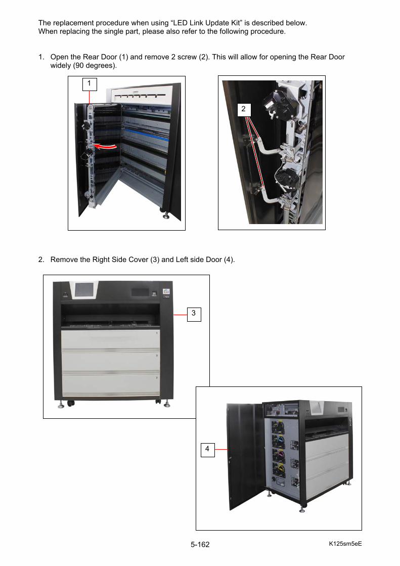
K125sm5eE 5-162
The replacement procedure when using “LED Link Update Kit” is described below. When replacing the single part, please also refer to the following procedure. 1. Open the Rear Door (1) and remove 2 screw (2). This will allow for opening the Rear Door
widely (90 degrees). 2. Remove the Right Side Cover (3) and Left side Door (4).
1
3
2
4

K125sm5eE 5-163
3. Draw out each Process Unit, remove the Drum (5) (K, C, M, Y) and put it in the Drum Packing Box. (Make sure to remove all Drums and put them into the Drum Packaging Box so as not to expose them to light)
4. Remove both Image Corona (6) and LED Head (7).
5
6
7
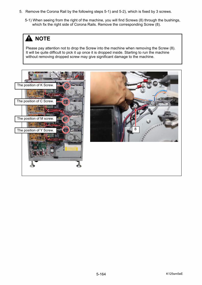
K125sm5eE 5-164
5. Remove the Corona Rail by the following steps 5-1) and 5-2), which is fixed by 3 screws.
5-1) When seeing from the right of the machine, you will find Screws (8) through the bushings, which fix the right side of Corona Rails. Remove the corresponding Screw (8).
8
The position of K Screw.
The position of C Screw.
The position of M screw.
The position of Y Screw.
NOTE Please pay attention not to drop the Screw into the machine when removing the Screw (8). It will be quite difficult to pick it up once it is dropped inside. Starting to run the machine without removing dropped screw may give significant damage to the machine.
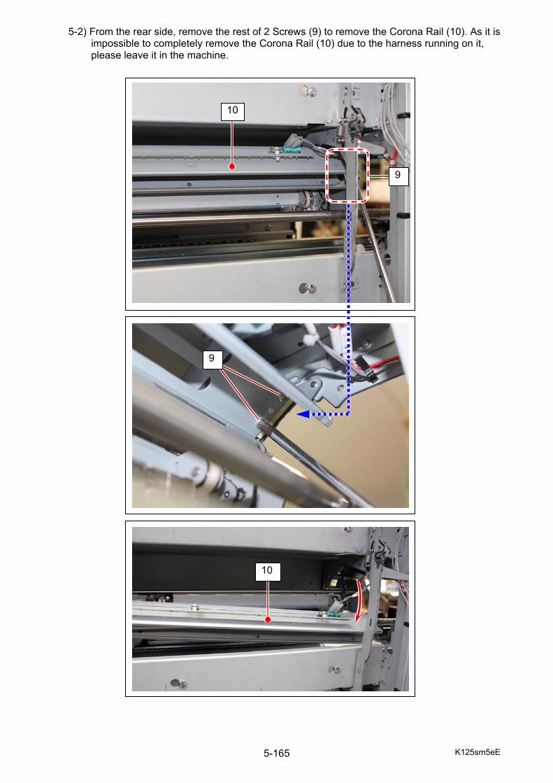
K125sm5eE 5-165
5-2) From the rear side, remove the rest of 2 Screws (9) to remove the Corona Rail (10). As it is impossible to completely remove the Corona Rail (10) due to the harness running on it, please leave it in the machine.
10
9
9
10
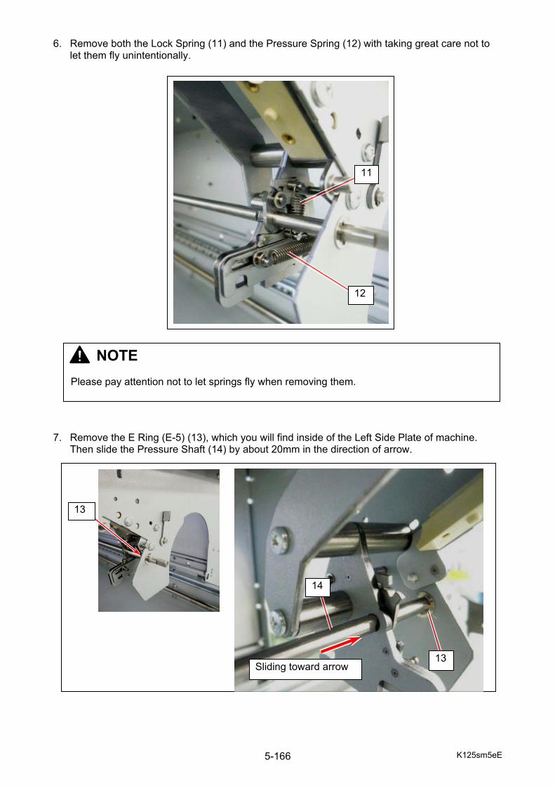
K125sm5eE 5-166
6. Remove both the Lock Spring (11) and the Pressure Spring (12) with taking great care not to
let them fly unintentionally.
7. Remove the E Ring (E-5) (13), which you will find inside of the Left Side Plate of machine.
Then slide the Pressure Shaft (14) by about 20mm in the direction of arrow.
11
12
13 Sliding toward arrow
14
13
NOTE Please pay attention not to let springs fly when removing them.
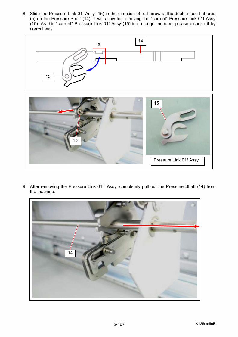
K125sm5eE 5-167
8. Slide the Pressure Link 01f Assy (15) in the direction of red arrow at the double-face flat area (a) on the Pressure Shaft (14). It will allow for removing the “current” Pressure Link 01f Assy (15). As this “current” Pressure Link 01f Assy (15) is no longer needed, please dispose it by correct way.
9. After removing the Pressure Link 01f Assy, completely pull out the Pressure Shaft (14) from
the machine.
a 14
15
Pressure Link 01f Assy
15
15
14
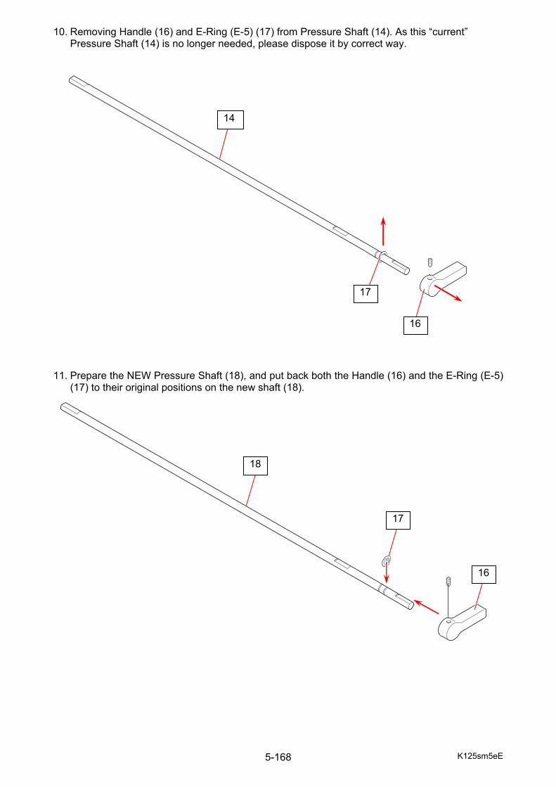
K125sm5eE 5-168
10. Removing Handle (16) and E-Ring (E-5) (17) from Pressure Shaft (14). As this “current” Pressure Shaft (14) is no longer needed, please dispose it by correct way.
11. Prepare the NEW Pressure Shaft (18), and put back both the Handle (16) and the E-Ring (E-5)
(17) to their original positions on the new shaft (18).
17
16
18
14
16
17
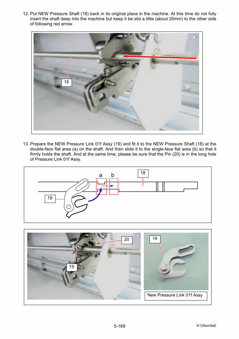
K125sm5eE 5-169
12. Put NEW Pressure Shaft (18) back in its original place in the machine. At this time do not fully insert the shaft deep into the machine but keep it be slid a little (about 20mm) to the other side of following red arrow.
13. Prepare the NEW Pressure Link 01f Assy (19) and fit it to the NEW Pressure Shaft (18) at the
double-face flat area (a) on the shaft. And then slide it to the single-face flat area (b) so that it firmly holds the shaft. And at the same time, please be sure that the Pin (20) is in the long hole of Pressure Link 01f Assy.
a 18
19
b
18
New Pressure Link 01f Assy
19
1920

K125sm5eE 5-170
14. On the other side of the machine (right side when seen from the front), insert the D-shape tip (21) of Pressure Shaft (18) to the D shape hole of Pressure Link 04b (22) then to the circular hole (23) of Pressure BKT (23).
15. Put E-Ring (E-5) (13) back in original place.
21
22
13
18
22
23
24
21
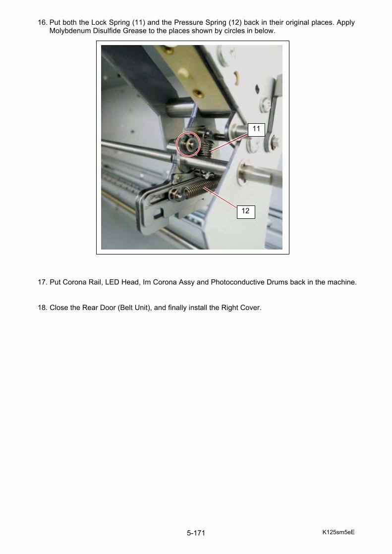
K125sm5eE 5-171
16. Put both the Lock Spring (11) and the Pressure Spring (12) back in their original places. Apply Molybdenum Disulfide Grease to the places shown by circles in below.
17. Put Corona Rail, LED Head, Im Corona Assy and Photoconductive Drums back in the machine.
18. Close the Rear Door (Belt Unit), and finally install the Right Cover.
11
12

K125sm6e1 6-1
Chapter 6
Maintenance
Page 6. 1 Recommended Periodic Replacement Parts 6- 2 6. 2 Periodical Maintenance 6- 3
6. 2. 1 Cleaning of Developer Roller 6- 4 6. 3 Recommended Service Tools & Devices 6- 6 6. 4 Internal Battery in Embedded Controller 6- 8 6. 5 Disposal of machine 6- 9

K125sm6e1 6-2
6. 1 Recommended Periodic Replacement Parts For keeping the machine quality in a satisfactory level, a periodic replacement for the following parts is recommended. A damaged part (even if it looks not) may result in a critical failure.
Part Name Contents Quantity Remarks Web - 1 Drum Kit DRUM 1
BRADE 1 SHEET 1 SEAL8 1 SEAL 10 2 SEAL 12 1 SEAL 13 1 SEAL 14 2 SEAL 15 1 SHEET 4 2
1st Set Corona Wire 1 Cleaning Pad Assy 2
BC Blade - 1 Cleaning Blade of Belt Cleaner Unit Developer Roller Kit BLADE ASSY 1
ROLLER DEVELOPER 1 BIAS TERMINAL 2 SEAL 17 2 SEAL 2 1 FLANGE 2 ASSY 1 SEAL 1 SIDE SEAL 10 4 SIDE SEAL 11 2 SIDE SEAL 12 2 BIAS TERMINAL 4 1 BIAS TERMINAL 5 1
Filter - 4 Ozone filters Fuser Kit Roller Fusing 1
Roller Pressure 1 Stripper Finger 13 ISOLATE BUSHING 4 COLLAR 1
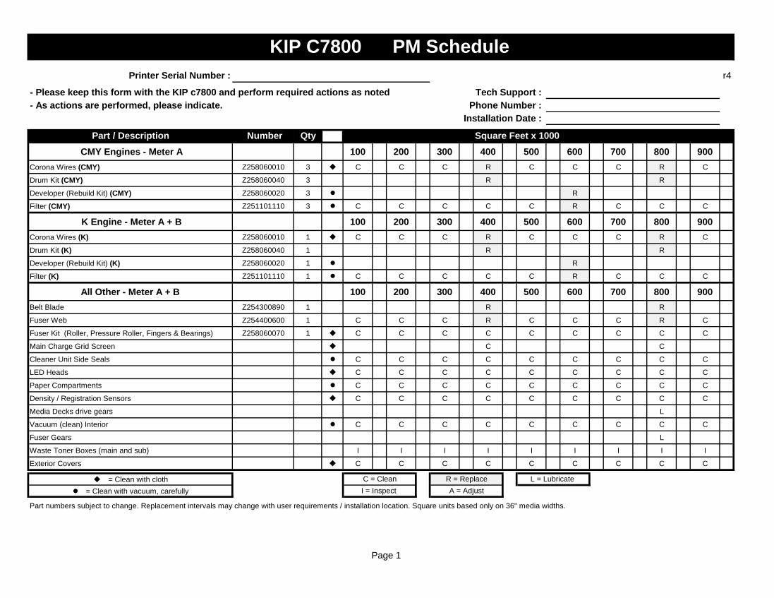
Page 1
Printer Serial Number : r4
- Please keep this form with the KIP c7800 and perform required actions as noted Tech Support : - As actions are performed, please indicate. Phone Number :
Installation Date :
Part / Description Number Qty Square Feet x 1000 CMY Engines - Meter A 100 200 300 400 500 600 700 800 900
Corona Wires (CMY) Z258060010 3 C C C R C C C R C
Drum Kit (CMY) Z258060040 3 R R
Developer (Rebuild Kit) (CMY) Z258060020 3 R
Filter (CMY) Z251101110 3 C C C C C R C C C
K Engine - Meter A + B 100 200 300 400 500 600 700 800 900Corona Wires (K) Z258060010 1 C C C R C C C R C
Drum Kit (K) Z258060040 1 R R
Developer (Rebuild Kit) (K) Z258060020 1 R
Filter (K) Z251101110 1 C C C C C R C C C
All Other - Meter A + B 100 200 300 400 500 600 700 800 900Belt Blade Z254300890 1 R R
Fuser Web Z254400600 1 C C C R C C C R C
Fuser Kit (Roller, Pressure Roller, Fingers & Bearings) Z258060070 1 C C C C C C C C C
Main Charge Grid Screen C C
Cleaner Unit Side Seals C C C C C C C C C
LED Heads C C C C C C C C C
Paper Compartments C C C C C C C C C
Density / Registration Sensors C C C C C C C C C
Media Decks drive gears L
Vacuum (clean) Interior C C C C C C C C C
Fuser Gears L
Waste Toner Boxes (main and sub) I I I I I I I I I
Exterior Covers C C C C C C C C C
= Clean with cloth = Clean with vacuum, carefully
Part numbers subject to change. Replacement intervals may change with user requirements / installation location. Square units based only on 36" media widths.
KIP C7800 PM Schedule
I = Inspect A = AdjustC = Clean R = Replace L = Lubricate
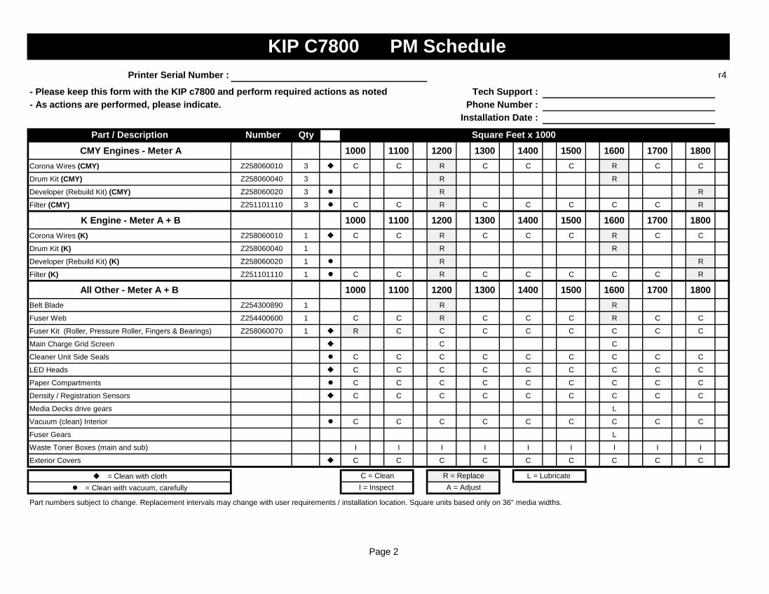
Page 2
Printer Serial Number : r4
- Please keep this form with the KIP c7800 and perform required actions as noted Tech Support : - As actions are performed, please indicate. Phone Number :
Installation Date :
Part / Description Number Qty Square Feet x 1000 CMY Engines - Meter A 1000 1100 1200 1300 1400 1500 1600 1700 1800
Corona Wires (CMY) Z258060010 3 C C R C C C R C C
Drum Kit (CMY) Z258060040 3 R R
Developer (Rebuild Kit) (CMY) Z258060020 3 R R
Filter (CMY) Z251101110 3 C C R C C C C C R
K Engine - Meter A + B 1000 1100 1200 1300 1400 1500 1600 1700 1800Corona Wires (K) Z258060010 1 C C R C C C R C C
Drum Kit (K) Z258060040 1 R R
Developer (Rebuild Kit) (K) Z258060020 1 R R
Filter (K) Z251101110 1 C C R C C C C C R
All Other - Meter A + B 1000 1100 1200 1300 1400 1500 1600 1700 1800Belt Blade Z254300890 1 R R
Fuser Web Z254400600 1 C C R C C C R C C
Fuser Kit (Roller, Pressure Roller, Fingers & Bearings) Z258060070 1 R C C C C C C C C
Main Charge Grid Screen C C
Cleaner Unit Side Seals C C C C C C C C C
LED Heads C C C C C C C C C
Paper Compartments C C C C C C C C C
Density / Registration Sensors C C C C C C C C C
Media Decks drive gears L
Vacuum (clean) Interior C C C C C C C C C
Fuser Gears L
Waste Toner Boxes (main and sub) I I I I I I I I I
Exterior Covers C C C C C C C C C
= Clean with cloth = Clean with vacuum, carefully
Part numbers subject to change. Replacement intervals may change with user requirements / installation location. Square units based only on 36" media widths.
KIP C7800 PM Schedule
C = Clean R = Replace L = Lubricate I = Inspect A = Adjust
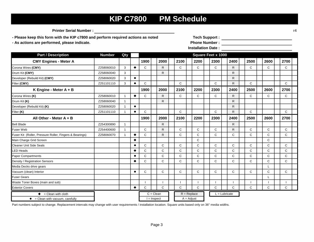
Page 3
Printer Serial Number : r4
- Please keep this form with the KIP c7800 and perform required actions as noted Tech Support : - As actions are performed, please indicate. Phone Number :
Installation Date :
Part / Description Number Qty Square Feet x 1000 CMY Engines - Meter A 1900 2000 2100 2200 2300 2400 2500 2600 2700
Corona Wires (CMY) Z258060010 3 C R C C C R C C C
Drum Kit (CMY) Z258060040 3 R R
Developer (Rebuild Kit) (CMY) Z258060020 3 R
Filter (CMY) Z251101110 3 C C C R C C
K Engine - Meter A + B 1900 2000 2100 2200 2300 2400 2500 2600 2700Corona Wires (K) Z258060010 1 C R C C C R C C C
Drum Kit (K) Z258060040 1 R R
Developer (Rebuild Kit) (K) Z258060020 1 R
Filter (K) Z251101110 1 C C C R C C
All Other - Meter A + B 1900 2000 2100 2200 2300 2400 2500 2600 2700Belt Blade Z254300890 1 R R
Fuser Web Z254400600 1 C R C C C R C C C
Fuser Kit (Roller, Pressure Roller, Fingers & Bearings) Z258060070 1 C R C C C C C C C
Main Charge Grid Screen C C
Cleaner Unit Side Seals C C C C C C C C C
LED Heads C C C C C C C C C
Paper Compartments C C C C C C C C C
Density / Registration Sensors C C C C C C C C C
Media Decks drive gears L
Vacuum (clean) Interior C C C C C C C C C
Fuser Gears L
Waste Toner Boxes (main and sub) I I I I I I I I I
Exterior Covers C C C C C C C C C
= Clean with cloth = Clean with vacuum, carefully
Part numbers subject to change. Replacement intervals may change with user requirements / installation location. Square units based only on 36" media widths.
KIP C7800 PM Schedule
C = Clean R = Replace L = Lubricate I = Inspect A = Adjust

Page 4
Printer Serial Number : r4
- Please keep this form with the KIP c7800 and perform required actions as noted Tech Support : - As actions are performed, please indicate. Phone Number :
Installation Date :
Part / Description Number Qty Square Feet x 1000 CMY Engines - Meter A 2800 2900 3000 3100 3200 3300 3400 3500 3600
Corona Wires (CMY) Z258060010 3 R C C C R C C C R
Drum Kit (CMY) Z258060040 3 R R R
Developer (Rebuild Kit) (CMY) Z258060020 3 R R
Filter (CMY) Z251101110 3 C R C C C R
K Engine - Meter A + B 2800 2900 3000 3100 3200 3300 3400 3500 3600Corona Wires (K) Z258060010 1 R C C C R C C C R
Drum Kit (K) Z258060040 1 R R R
Developer (Rebuild Kit) (K) Z258060020 1 R R
Filter (K) Z251101110 1 C R C C C R
All Other - Meter A + B 2800 2900 3000 3100 3200 3300 3400 3500 3600Belt Blade Z254300890 1 R R R
Fuser Web Z254400600 1 R C C C R C C C R
Fuser Kit (Roller, Pressure Roller, Fingers & Bearings) Z258060070 1 C C R C C C C C C
Main Charge Grid Screen C C
Cleaner Unit Side Seals C C C C C C C C C
LED Heads C C C C C C C C C
Paper Compartments C C C C C C C C C
Density / Registration Sensors C C C C C C C C C
Media Decks drive gears L
Vacuum (clean) Interior C C C C C C C C C
Fuser Gears L
Waste Toner Boxes (main and sub) I I I I I I I I I
Exterior Covers C C C C C C C C C
= Clean with cloth = Clean with vacuum, carefully
Part numbers subject to change. Replacement intervals may change with user requirements / installation location. Square units based only on 36" media widths.
KIP C7800 PM Schedule
C = Clean R = Replace L = Lubricate I = Inspect A = Adjust
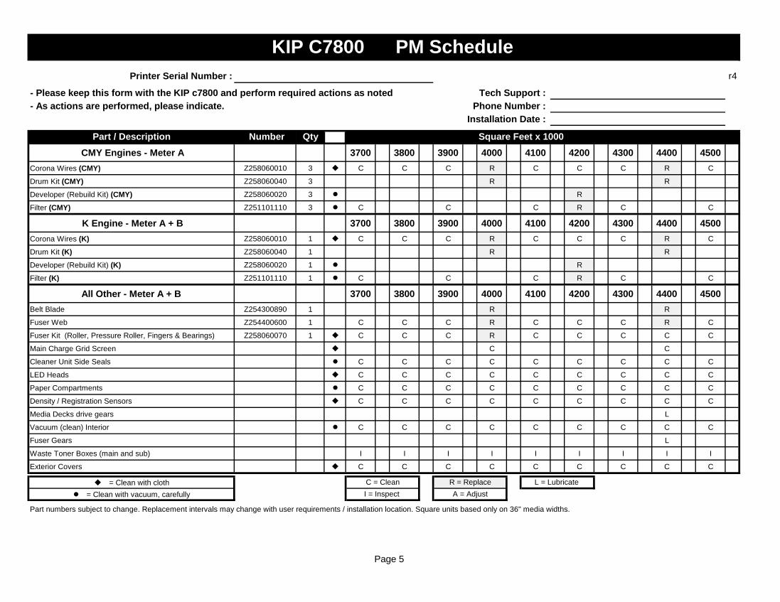
Page 5
Printer Serial Number : r4
- Please keep this form with the KIP c7800 and perform required actions as noted Tech Support : - As actions are performed, please indicate. Phone Number :
Installation Date :
Part / Description Number Qty Square Feet x 1000 CMY Engines - Meter A 3700 3800 3900 4000 4100 4200 4300 4400 4500
Corona Wires (CMY) Z258060010 3 C C C R C C C R C
Drum Kit (CMY) Z258060040 3 R R
Developer (Rebuild Kit) (CMY) Z258060020 3 R
Filter (CMY) Z251101110 3 C C C R C C
K Engine - Meter A + B 3700 3800 3900 4000 4100 4200 4300 4400 4500Corona Wires (K) Z258060010 1 C C C R C C C R C
Drum Kit (K) Z258060040 1 R R
Developer (Rebuild Kit) (K) Z258060020 1 R
Filter (K) Z251101110 1 C C C R C C
All Other - Meter A + B 3700 3800 3900 4000 4100 4200 4300 4400 4500Belt Blade Z254300890 1 R R
Fuser Web Z254400600 1 C C C R C C C R C
Fuser Kit (Roller, Pressure Roller, Fingers & Bearings) Z258060070 1 C C C R C C C C C
Main Charge Grid Screen C C
Cleaner Unit Side Seals C C C C C C C C C
LED Heads C C C C C C C C C
Paper Compartments C C C C C C C C C
Density / Registration Sensors C C C C C C C C C
Media Decks drive gears L
Vacuum (clean) Interior C C C C C C C C C
Fuser Gears L
Waste Toner Boxes (main and sub) I I I I I I I I I
Exterior Covers C C C C C C C C C
= Clean with cloth = Clean with vacuum, carefully
Part numbers subject to change. Replacement intervals may change with user requirements / installation location. Square units based only on 36" media widths.
KIP C7800 PM Schedule
C = Clean R = Replace L = Lubricate I = Inspect A = Adjust

Page 6
Printer Serial Number : r4
- Please keep this form with the KIP c7800 and perform required actions as noted Tech Support : - As actions are performed, please indicate. Phone Number :
Installation Date :
Part / Description Number Qty Square Feet x 1000 CMY Engines - Meter A 4600 4700 4800 4900 5000 5100 5200 5300 5400
Corona Wires (CMY) Z258060010 3 C C R C C C R C C
Drum Kit (CMY) Z258060040 3 R R
Developer (Rebuild Kit) (CMY) Z258060020 3 R R
Filter (CMY) Z251101110 3 C R C C C R
K Engine - Meter A + B 4600 4700 4800 4900 5000 5100 5200 5300 5400Corona Wires (K) Z258060010 1 C C R C C C R C C
Drum Kit (K) Z258060040 1 R R
Developer (Rebuild Kit) (K) Z258060020 1 R R
Filter (K) Z251101110 1 C R C C C R
All Other - Meter A + B 4600 4700 4800 4900 5000 5100 5200 5300 5400Belt Blade Z254300890 1 R R
Fuser Web Z254400600 1 C C R C C C R C C
Fuser Kit (Roller, Pressure Roller, Fingers & Bearings) Z258060070 1 C C C C R C C C C
Main Charge Grid Screen C C
Cleaner Unit Side Seals C C C C C C C C C
LED Heads C C C C C C C C C
Paper Compartments C C C C C C C C C
Density / Registration Sensors C C C C C C C C C
Media Decks drive gears L
Vacuum (clean) Interior C C C C C C C C C
Fuser Gears L
Waste Toner Boxes (main and sub) I I I I I I I I I
Exterior Covers C C C C C C C C C
= Clean with cloth = Clean with vacuum, carefully
Part numbers subject to change. Replacement intervals may change with user requirements / installation location. Square units based only on 36" media widths.
KIP C7800 PM Schedule
C = Clean R = Replace L = Lubricate I = Inspect A = Adjust
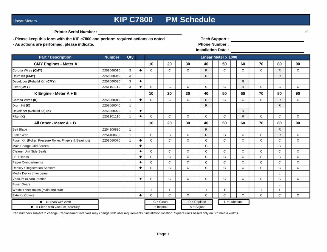
Page 1
Linear Meters
Printer Serial Number : r1
- Please keep this form with the KIP c7800 and perform required actions as noted Tech Support : - As actions are performed, please indicate. Phone Number :
Installation Date :
Part / Description Number Qty Linear Meter x 1000 CMY Engines - Meter A 10 20 30 40 50 60 70 80 90
Corona Wires (CMY) Z258060010 3 C C C R C C C R C
Drum Kit (CMY) Z258060040 3 R R
Developer (Rebuild Kit) (CMY) Z258060020 3 R
Filter (CMY) Z251101110 3 C C C C C R C C C
K Engine - Meter A + B 10 20 30 40 50 60 70 80 90Corona Wires (K) Z258060010 1 C C C R C C C R C
Drum Kit (K) Z258060040 1 R R
Developer (Rebuild Kit) (K) Z258060020 1 R
Filter (K) Z251101110 1 C C C C C R C C C
All Other - Meter A + B 10 20 30 40 50 60 70 80 90Belt Blade Z254300890 1 R R
Fuser Web Z254400600 1 C C C R C C C R C
Fuser Kit (Roller, Pressure Roller, Fingers & Bearings) Z258060070 1 C C C C C C C C C
Main Charge Grid Screen C C
Cleaner Unit Side Seals C C C C C C C C C
LED Heads C C C C C C C C C
Paper Compartments C C C C C C C C C
Density / Registration Sensors C C C C C C C C C
Media Decks drive gears L
Vacuum (clean) Interior C C C C C C C C C
Fuser Gears L
Waste Toner Boxes (main and sub) I I I I I I I I I
Exterior Covers C C C C C C C C C
= Clean with cloth = Clean with vacuum, carefully
Part numbers subject to change. Replacement intervals may change with user requirements / installation location. Square units based only on 36" media widths.
KIP C7800 PM Schedule
I = Inspect A = AdjustC = Clean R = Replace L = Lubricate
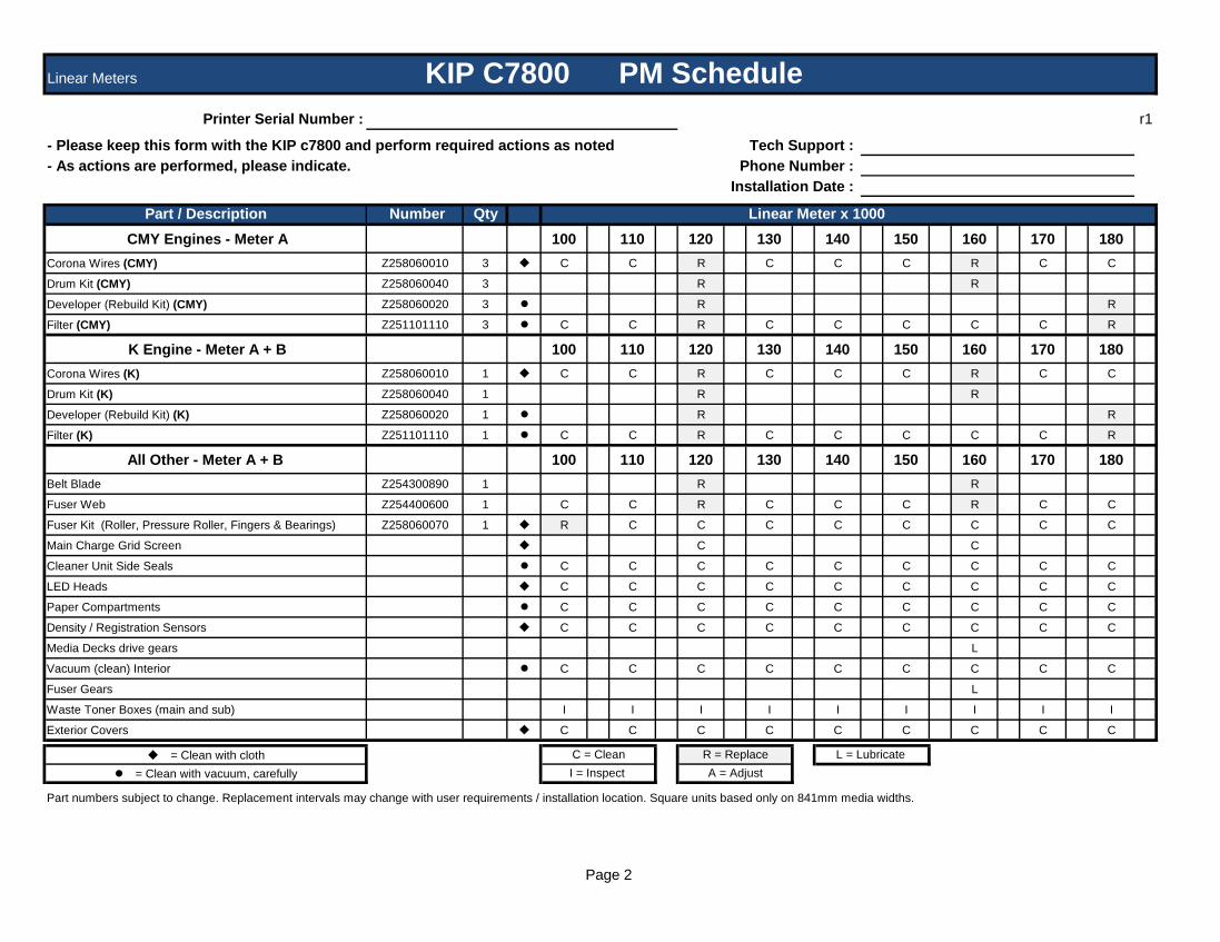
Page 2
Linear Meters
Printer Serial Number : r1
- Please keep this form with the KIP c7800 and perform required actions as noted Tech Support : - As actions are performed, please indicate. Phone Number :
Installation Date :
Part / Description Number Qty Linear Meter x 1000 CMY Engines - Meter A 100 110 120 130 140 150 160 170 180
Corona Wires (CMY) Z258060010 3 C C R C C C R C C
Drum Kit (CMY) Z258060040 3 R R
Developer (Rebuild Kit) (CMY) Z258060020 3 R R
Filter (CMY) Z251101110 3 C C R C C C C C R
K Engine - Meter A + B 100 110 120 130 140 150 160 170 180Corona Wires (K) Z258060010 1 C C R C C C R C C
Drum Kit (K) Z258060040 1 R R
Developer (Rebuild Kit) (K) Z258060020 1 R R
Filter (K) Z251101110 1 C C R C C C C C R
All Other - Meter A + B 100 110 120 130 140 150 160 170 180Belt Blade Z254300890 1 R R
Fuser Web Z254400600 1 C C R C C C R C C
Fuser Kit (Roller, Pressure Roller, Fingers & Bearings) Z258060070 1 R C C C C C C C C
Main Charge Grid Screen C C
Cleaner Unit Side Seals C C C C C C C C C
LED Heads C C C C C C C C C
Paper Compartments C C C C C C C C C
Density / Registration Sensors C C C C C C C C C
Media Decks drive gears L
Vacuum (clean) Interior C C C C C C C C C
Fuser Gears L
Waste Toner Boxes (main and sub) I I I I I I I I I
Exterior Covers C C C C C C C C C
= Clean with cloth = Clean with vacuum, carefully
Part numbers subject to change. Replacement intervals may change with user requirements / installation location. Square units based only on 841mm media widths.
KIP C7800 PM Schedule
C = Clean R = Replace L = Lubricate I = Inspect A = Adjust

Page 3
Linear Meters
Printer Serial Number : r1
- Please keep this form with the KIP c7800 and perform required actions as noted Tech Support : - As actions are performed, please indicate. Phone Number :
Installation Date :
Part / Description Number Qty Linear Meter x 1000 CMY Engines - Meter A 190 200 210 220 230 240 250 260 270
Corona Wires (CMY) Z258060010 3 C R C C C R C C C
Drum Kit (CMY) Z258060040 3 R R
Developer (Rebuild Kit) (CMY) Z258060020 3 R
Filter (CMY) Z251101110 3 C C C R C C
K Engine - Meter A + B 190 200 210 220 230 240 250 260 270Corona Wires (K) Z258060010 1 C R C C C R C C C
Drum Kit (K) Z258060040 1 R R
Developer (Rebuild Kit) (K) Z258060020 1 R
Filter (K) Z251101110 1 C C C R C C
All Other - Meter A + B 190 200 210 220 230 240 250 260 270Belt Blade Z254300890 1 R R
Fuser Web Z254400600 1 C R C C C R C C C
Fuser Kit (Roller, Pressure Roller, Fingers & Bearings) Z258060070 1 C R C C C C C C C
Main Charge Grid Screen C C
Cleaner Unit Side Seals C C C C C C C C C
LED Heads C C C C C C C C C
Paper Compartments C C C C C C C C C
Density / Registration Sensors C C C C C C C C C
Media Decks drive gears L
Vacuum (clean) Interior C C C C C C C C C
Fuser Gears L
Waste Toner Boxes (main and sub) I I I I I I I I I
Exterior Covers C C C C C C C C C
= Clean with cloth = Clean with vacuum, carefully
Part numbers subject to change. Replacement intervals may change with user requirements / installation location. Square units based only on 841mm media widths.
KIP C7800 PM Schedule
C = Clean R = Replace L = Lubricate I = Inspect A = Adjust

Page 4
Linear Meters
Printer Serial Number : r1
- Please keep this form with the KIP c7800 and perform required actions as noted Tech Support : - As actions are performed, please indicate. Phone Number :
Installation Date :
Part / Description Number Qty Linear Meter x 1000 CMY Engines - Meter A 280 290 300 310 320 330 340 350 360
Corona Wires (CMY) Z258060010 3 R C C C R C C C R
Drum Kit (CMY) Z258060040 3 R R R
Developer (Rebuild Kit) (CMY) Z258060020 3 R R
Filter (CMY) Z251101110 3 C R C C C R
K Engine - Meter A + B 280 290 300 310 320 330 340 350 360Corona Wires (K) Z258060010 1 R C C C R C C C R
Drum Kit (K) Z258060040 1 R R R
Developer (Rebuild Kit) (K) Z258060020 1 R R
Filter (K) Z251101110 1 C R C C C R
All Other - Meter A + B 280 290 300 310 320 330 340 350 360Belt Blade Z254300890 1 R R R
Fuser Web Z254400600 1 R C C C R C C C R
Fuser Kit (Roller, Pressure Roller, Fingers & Bearings) Z258060070 1 C C R C C C C C C
Main Charge Grid Screen C C
Cleaner Unit Side Seals C C C C C C C C C
LED Heads C C C C C C C C C
Paper Compartments C C C C C C C C C
Density / Registration Sensors C C C C C C C C C
Media Decks drive gears L
Vacuum (clean) Interior C C C C C C C C C
Fuser Gears L
Waste Toner Boxes (main and sub) I I I I I I I I I
Exterior Covers C C C C C C C C C
= Clean with cloth = Clean with vacuum, carefully
Part numbers subject to change. Replacement intervals may change with user requirements / installation location. Square units based only on 841mm media widths.
KIP C7800 PM Schedule
C = Clean R = Replace L = Lubricate I = Inspect A = Adjust
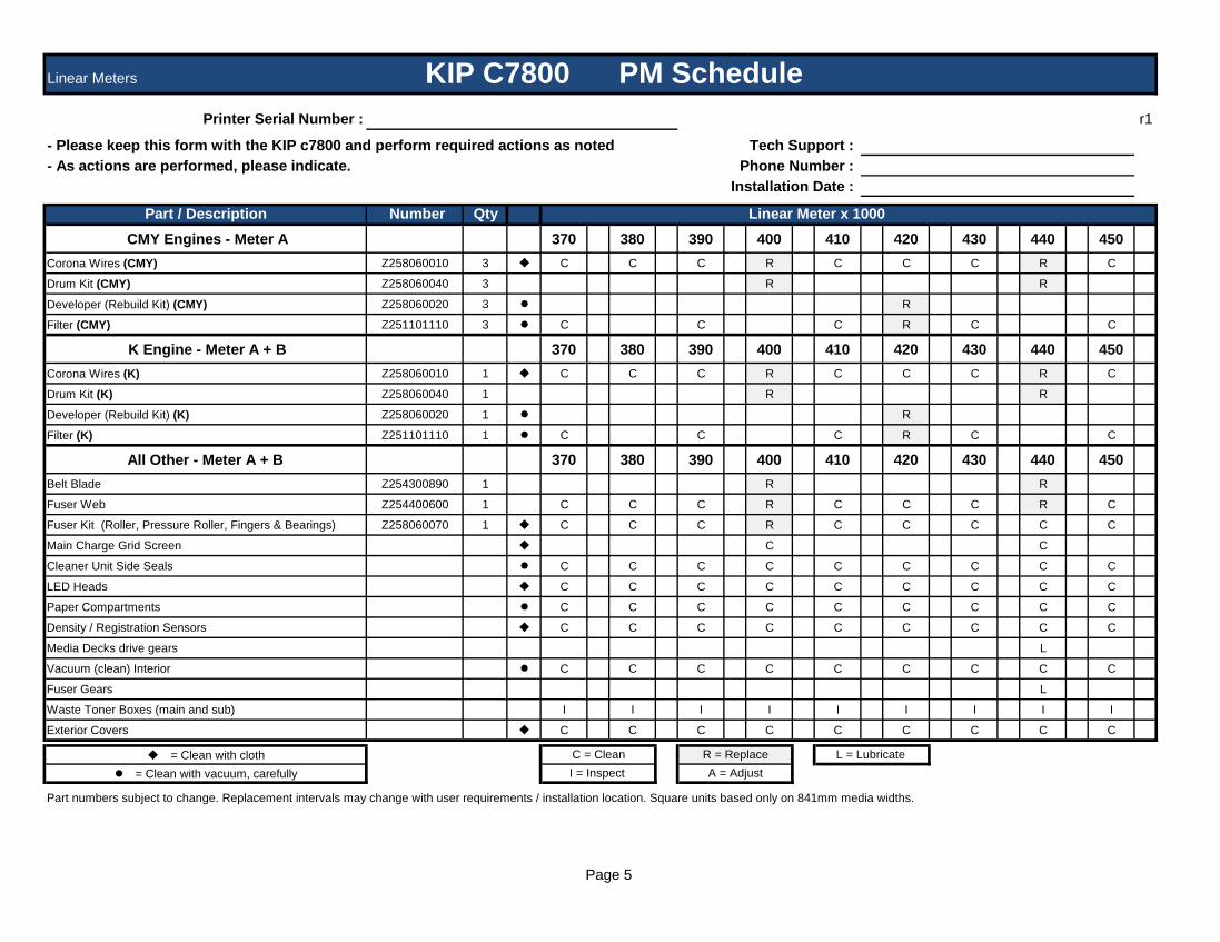
Page 5
Linear Meters
Printer Serial Number : r1
- Please keep this form with the KIP c7800 and perform required actions as noted Tech Support : - As actions are performed, please indicate. Phone Number :
Installation Date :
Part / Description Number Qty Linear Meter x 1000 CMY Engines - Meter A 370 380 390 400 410 420 430 440 450
Corona Wires (CMY) Z258060010 3 C C C R C C C R C
Drum Kit (CMY) Z258060040 3 R R
Developer (Rebuild Kit) (CMY) Z258060020 3 R
Filter (CMY) Z251101110 3 C C C R C C
K Engine - Meter A + B 370 380 390 400 410 420 430 440 450Corona Wires (K) Z258060010 1 C C C R C C C R C
Drum Kit (K) Z258060040 1 R R
Developer (Rebuild Kit) (K) Z258060020 1 R
Filter (K) Z251101110 1 C C C R C C
All Other - Meter A + B 370 380 390 400 410 420 430 440 450Belt Blade Z254300890 1 R R
Fuser Web Z254400600 1 C C C R C C C R C
Fuser Kit (Roller, Pressure Roller, Fingers & Bearings) Z258060070 1 C C C R C C C C C
Main Charge Grid Screen C C
Cleaner Unit Side Seals C C C C C C C C C
LED Heads C C C C C C C C C
Paper Compartments C C C C C C C C C
Density / Registration Sensors C C C C C C C C C
Media Decks drive gears L
Vacuum (clean) Interior C C C C C C C C C
Fuser Gears L
Waste Toner Boxes (main and sub) I I I I I I I I I
Exterior Covers C C C C C C C C C
= Clean with cloth = Clean with vacuum, carefully
Part numbers subject to change. Replacement intervals may change with user requirements / installation location. Square units based only on 841mm media widths.
KIP C7800 PM Schedule
C = Clean R = Replace L = Lubricate I = Inspect A = Adjust

Page 6
Linear Meters
Printer Serial Number : r1
- Please keep this form with the KIP c7800 and perform required actions as noted Tech Support : - As actions are performed, please indicate. Phone Number :
Installation Date :
Part / Description Number Qty Linear Meter x 1000 CMY Engines - Meter A 460 470 480 490 500 510 520 530 540
Corona Wires (CMY) Z258060010 3 C C R C C C R C C
Drum Kit (CMY) Z258060040 3 R R
Developer (Rebuild Kit) (CMY) Z258060020 3 R R
Filter (CMY) Z251101110 3 C R C C C R
K Engine - Meter A + B 460 470 480 490 500 510 520 530 540Corona Wires (K) Z258060010 1 C C R C C C R C C
Drum Kit (K) Z258060040 1 R R
Developer (Rebuild Kit) (K) Z258060020 1 R R
Filter (K) Z251101110 1 C R C C C R
All Other - Meter A + B 460 470 480 490 500 510 520 530 540Belt Blade Z254300890 1 R R
Fuser Web Z254400600 1 C C R C C C R C C
Fuser Kit (Roller, Pressure Roller, Fingers & Bearings) Z258060070 1 C C C C R C C C C
Main Charge Grid Screen C C
Cleaner Unit Side Seals C C C C C C C C C
LED Heads C C C C C C C C C
Paper Compartments C C C C C C C C C
Density / Registration Sensors C C C C C C C C C
Media Decks drive gears L
Vacuum (clean) Interior C C C C C C C C C
Fuser Gears L
Waste Toner Boxes (main and sub) I I I I I I I I I
Exterior Covers C C C C C C C C C
= Clean with cloth = Clean with vacuum, carefully
Part numbers subject to change. Replacement intervals may change with user requirements / installation location. Square units based only on 841mm media widths.
KIP C7800 PM Schedule
C = Clean R = Replace L = Lubricate I = Inspect A = Adjust

KIP C7800 Printer Preventative Maintenance
Procedure performed each 100,000 sq ft of: Meter A
Meter A + B
Step #1 - Prepare Machine Ask User about printer performance / image quality Print internal test prints and review quality Locate the “KIP C7800 PM Schedule” form and check off each item completed.
Replace noted items as this procedure progresses.
Step #2 - Corona Units x4 Clean 1st Charge wires and cases (Glass cleaner) Clean Grid Screen (use Simple Green, then rinse with water) Let dry on paper
towel /cloth.
Step #3 - Development Unit x4 Vacuum toner dust from ends of developer unit and around toner hopper inlet. Inspect all Development Rollers (Clean if required) Clean and lube gears as needed. (G501 grease / Lithium grease) Carefully vacuum drum cleaner blade side seals
Step #4 - Paper Decks x3 Vacuum paper dust. Inspected paper spools. Clean paper dust from each knife assembly.
Step #5 - Clean Interior of Printer Clean Transport belts with water and clean cloth and then wipe dry (do not use
any solvents!) Transfer guide plates etc.
Step #6 - Fuser Section Clean upper Nails with a dry cloth. Clean lower Nails with a dry cloth. Clean and lubricate gears as needed with high temperature grease
Step #7 - L.E.D Print Head x4 Clean LED lens. (Glass cleaner) Carefully dust the Density and Registration sensors (do this item last)
Step #8 - Density / Tests Print TP #31 and #18 - verify image quality Perform Optical Density Calibration
Step #9 Clean Exterior Panels
r3
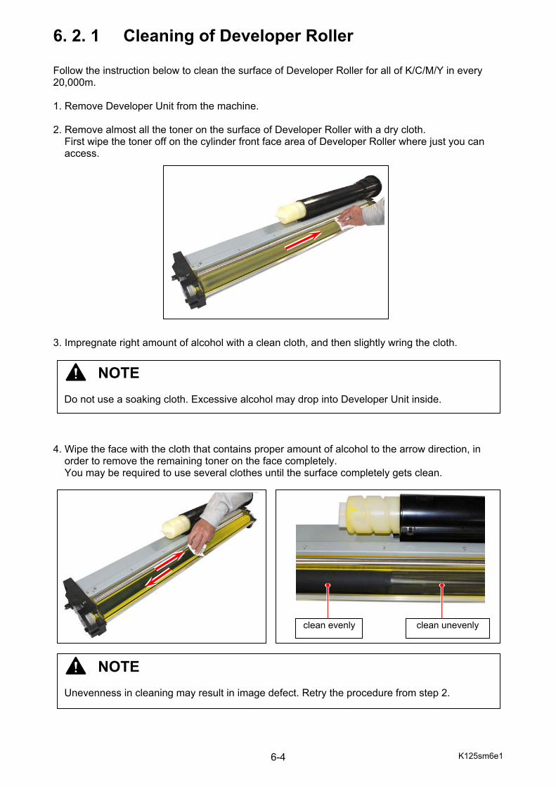
K125sm6e1 6-4
6. 2. 1 Cleaning of Developer Roller Follow the instruction below to clean the surface of Developer Roller for all of K/C/M/Y in every 20,000m. 1. Remove Developer Unit from the machine. 2. Remove almost all the toner on the surface of Developer Roller with a dry cloth.
First wipe the toner off on the cylinder front face area of Developer Roller where just you can access.
3. Impregnate right amount of alcohol with a clean cloth, and then slightly wring the cloth. 4. Wipe the face with the cloth that contains proper amount of alcohol to the arrow direction, in
order to remove the remaining toner on the face completely. You may be required to use several clothes until the surface completely gets clean.
NOTE Do not use a soaking cloth. Excessive alcohol may drop into Developer Unit inside.
clean evenly clean unevenly
NOTE Unevenness in cleaning may result in image defect. Retry the procedure from step 2.

K125sm6e1 6-5
5. Dry the face completely. Attach Dev Handle to the shaft of Developer Roller. Rotate Dev Handle to the arrow direction to face the next uncleaned area.
6. Wipe the next face in the same way of step 2 through 5.
7. Clean the whole surface of Developer Roller.
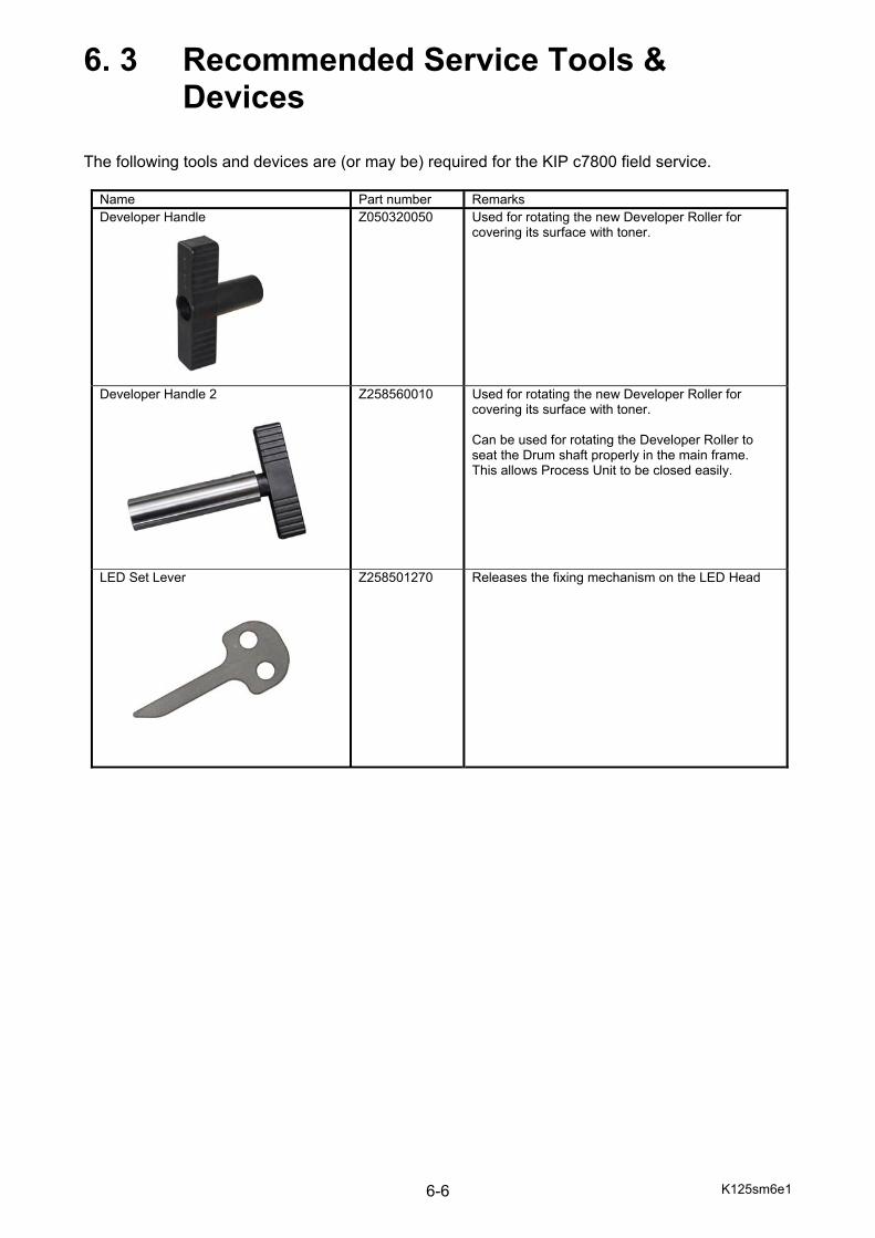
K125sm6e1 6-6
6. 3 Recommended Service Tools & Devices The following tools and devices are (or may be) required for the KIP c7800 field service.
Name Part number Remarks Developer Handle Z050320050
Used for rotating the new Developer Roller for covering its surface with toner.
Developer Handle 2 Z258560010 Used for rotating the new Developer Roller for covering its surface with toner. Can be used for rotating the Developer Roller to seat the Drum shaft properly in the main frame. This allows Process Unit to be closed easily.
LED Set Lever Z258501270 Releases the fixing mechanism on the LED Head

K125sm6e1 6-7
Name Part number Remarks Setup Toner (with case and brush) - This is used for applying the toner to;
- Cleaner Blade of Cleaner Unit at installation - Both side faces of new Cleaner Blade - Scraper of Developer Unit NOTE (1) Please use the toner from the Toner Cartridge. (2) Prepare the case and cosmetic brush to each color respectively to avoid the mixture of different color toner.
Water Level (0.02mm/1m) - This is used to level the printer to have correct Color Registration H. The specification is “0.02mm/1m”.
Densitometer - This is used to readjust the Target Density for some reason.
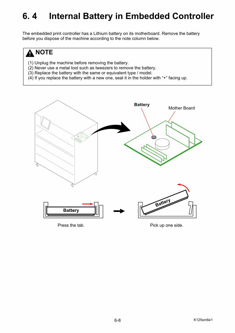
K125sm6e1 6-8
6. 4 Internal Battery in Embedded Controller The embedded print controller has a Lithium battery on its motherboard. Remove the battery before you dispose of the machine according to the note column below.
Battery Mother Board
Press the tab. Pick up one side.
NOTE
(1) Unplug the machine before removing the battery. (2) Never use a metal tool such as tweezers to remove the battery. (3) Replace the battery with the same or equivalent type / model. (4) If you replace the battery with a new one, seat it in the holder with “+” facing up.

K125sm6e1 6-9
6. 5 Disposal of machine Location of parts which should be removed from the waste machine 1. polychlorinated biphenyls (PCB) containing capacitors in accordance with Council Directive 96/59/EC of 16 September 1996 on the disposal of polychlorinated biphenyls and polychlorinated terphenyls (PCB/PCT)(1), 2. mercury containing components, such as switches or backlighting lamps, 3. batteries 4. printed circuit boards of mobile phones generally, and of other devices if the surface of the printed circuit board is greater than 10 square centimeters, 5. toner cartridges, liquid and pasty, as well as colour toner, 6. plastic containing brominated flame retardants, 7. liquid crystal displays (together with their casing where appropriate) of a surface greater than 100 square centimeters and all those back-lighted with gas discharge lamps, 8. external electric cables, 9. electrolyte capacitors containing substances of concern (height > 25 mm, diameter > 25 mm or proportionately similar volume)
3
4
4
4
4
4
4
4
2, 7
4
4
5
4
4
4
4
4
4
4
4
4
4
4
4
NOTE
The illustrated components below must be disposed of by a waste disposer.
NOTE
Flammable. Do not dispose of used toner or Toner Cartridge in the fire. Doing so may increase a risk of explosion.
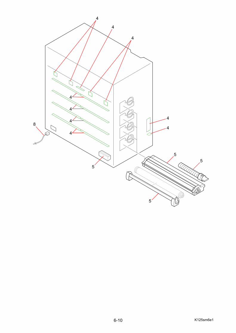
K125sm6e1 6-10
4
4
55
4
4
4
4
4
4
4
5
5
8

K125sm7e1
Chapter 7
Troubleshooting Page 7. 1 Operator Call Error 7- 1 7. 1. 1 Clearing Door Open Error 7- 1 U-1001, 1002, 1003 Roll Deck 1/2/3 Open 7- 1 U-1011, 1012, 1013 Roll Deck 1/2/3 Cutter Cover Open 7- 2 U-1100 Bypass Feeder Open 7- 2 U-1101 Left Side Door Open 7- 2 U-1103 Rear Door Open 7- 3 U-1104 Fuser Cover (Exit Door) Open 7- 3 U-1201, 1202, 1203, 1204 Process Unit 1/2/3/4 Open 7- 3 7. 1. 2 Clearing Jam Error 7- 4 J-0101 Roll Deck 1 Jam: Power ON 7- 4 J-0102 Roll Deck 2 Jam: Power ON 7- 5 J-0103 Roll Deck 3 Jam: Power ON 7- 5 J-0105 Bypass Feeder Jam: Power ON 7- 5 J-0111 Lower Feeder Jam: Power ON 7- 6 J-0112 Registration Jam: Power ON 7- 6 J-0131 Fuser Jam: Power ON 7- 6 J-0201 Roll Deck 1 Jam: LE Delay 7- 7 J-0202 Roll Deck 2 Jam: LE Delay 7- 7 J-0203 Roll Deck 3 Jam: LE Delay 7- 8 J-0205 Bypass Feeder Jam: LE Delay 7- 9 J-0211 Lower Feeder Jam: LE Delay 7-10 J-0231 Fuser Jam: LE Delay 7-11 J-0401 Roll Deck 1 Jam: Stay 7-12 J-0402 Roll Deck 2 Jam: Stay 7-12 J-0403 Roll Deck 3 Jam: Stay 7-13 J-0431 Fuser Jam: TE Stay 7-14 7. 1. 3 Other Operator Call Error 7-15 (1) Toner Empty 7-15 (2) Roll Empty 7-16 (3) Waste Toner Full 7-16 7. 2 Service Call Error 7-17 7. 2. 1 Clearing Service Call Error 7-17 01-11, 01-12, 01-13 Cutter Error 7-17 03-01 Dev Press Motor 1 Error 7-19 03-02 Drum Motor 1 Error 7-20 03-20 Image Corona 1 Output Error 7-21 03-21 Transfer Roller Bias 1 Output Error 7-21 03-23 Developer Bias 1 Output Error 7-21 03-30, 03-31, 03-32 LED Head 1 Error 7-22 03-36 Density Control 1 Error 7-22 03-40 Wire Cleaning Motor 1 Error 7-23 04-01 Dev Press Motor 2 Error 7-25 04-02 Drum Motor 2 Error 7-26 04-20 Image Corona 2 Output Error 7-27 04-21 Transfer Roller Bias 2 Output Error 7-27 04-23 Developer Bias 2 Output Error 7-27 04-30, 04-31, 04-32 LED Head 2 Error 7-28 04-36 Density Control 2 Error 7-28
K125sm7e1
04-40 Wire Cleaning Motor 2 Error 7-29 05-01 Dev Press Motor 3 Error 7-31 05-02 Drum Motor 3 Error 7-32 05-20 Image Corona 3 Output Error 7-33 05-21 Transfer Roller Bias 3 Output Error 7-33 05-23 Developer Bias 3 Output Error 7-33 05-30, 05-31, 05-32 LED Head 3 Error 7-34 05-36 Density Control 3 Error 7-34 05-40 Wire Cleaning Motor 3 Error 7-35 06-01 Dev Press Motor 4 Error 7-37 06-02 Drum Motor 4 Error 7-38 06-20 Image Corona 4 Output Error 7-39 06-21 Transfer Roller Bias 4 Output Error 7-39 06-23 Developer Bias 4 Output Error 7-39 06-30, 06-31, 06-32 LED Head 4 Error 7-40 06-36 Density Control 4 Error 7-40 06-40 Wire Cleaning Motor 4 Error 7-41 07-10 Media Charge Roller Set Motor Error 7-43 07-11 Transfer Roller Set Motor 1 Error 7-44 07-12 Transfer Roller Set Motor 2 Error 7-45 07-21, 07-22 Belt Skew Error 7-45 09-00 Fuser Temperature Rising Error 7-46 09-01 Fuser Abnormal High Temperature Error 7-47 09-02 Web End Error 7-48 09-03 Fuser Thermostat Error 7-48 0A-03 BUD Load Error 7-48 0A-20 Main Control PCB Communication Error 7-48 0A-21 Main Control PCB DDR Initialization Error 7-48 0C-01 Density Sensor Error 7-49 0C-11, 0C-12, 0C-13, 0C-14 Color Sensor Error 7-49 0C-21 LED Head Skew Adjustment Error 7-50 0C-22, 0C-23 LED Head Joint Adjustment Error 7-50 0C-24, 0C-25 Color Registration Calibration Error 7-50 0C-27 Cut Length Adjustment Error 7-50 0D-01, 0D-02, 0D-03, 0D-04 Cooling Fan Error 7-51 0D-05, 0D-06 DCP Cooling Fan Error 7-51 0D-07, 0D-08 IPS Cooling Fan Error 7-51 0D-09, 0D-0A Fuser Blower Error 7-52 7. 2. 2 Occurrence Condition of Service Call Error 7-53 7. 3 Troubleshooting - Image Quality 7-55 7. 3. 1 Basic Image Adjustment 7-55 7. 3. 2 Cause of Frequent Image Problem 7-56 7. 3. 3 Countermeasures - Image Quality 7-57 7. 3. 3. 1 Halftone is light (or dark) 7-57 7. 3. 3. 2 Halftone and solid images are too light 7-59 7. 3. 3. 3 Density is uneven 7-60 7. 3. 3. 4 Totally appeared foggy image 7-61 7. 3. 3. 5 Vertical thick line that looks not clear 7-62 7. 3. 3. 6 Vertical thin line that looks clear 7-63 7. 3. 3. 7 Vertical white line 7-64 7. 3. 3. 8 Void of image 7-65 7. 3. 3. 9 Dirt on the back of the print 7-66 7. 3. 3.10 Poor fusing 7-66 7. 3. 3.11 Complete white (No image) 7-67 7. 3. 3.12 Blur on dark image 7-68 7. 3 3.13 Complete solid image like “all black” 7-68 7. 3. 4 Checking for correct pressurization or Developer 7-69 7. 4 Internal Counter Error 7-73
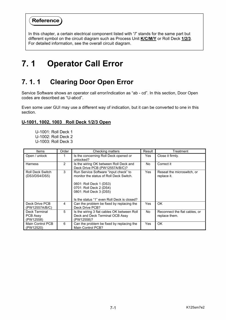
K125sm7e2 7-1
7. 1 Operator Call Error
7. 1. 1 Clearing Door Open Error Service Software shows an operator call error/indication as “ab - cd”. In this section, Door Open codes are described as “U-abcd”. Even some user GUI may use a different way of indication, but it can be converted to one in this section. U-1001, 1002, 1003 Roll Deck 1/2/3 Open U-1001: Roll Deck 1 U-1002: Roll Deck 2 U-1003: Roll Deck 3
Items Order Checking matters Result Treatment Open / unlock 1 Is the concerning Roll Deck opened or
unlocked? Yes Close it firmly.
Harness 2 Is the wiring OK between Roll Deck and Deck Drive PCB (PW12557A/B/C)?
No Correct it
Roll Deck Switch (DS3/DS4/DS5)
3 Run Service Software “input check” to monitor the status of Roll Deck Switch. 0601: Roll Deck 1 (DS3) 0701: Roll Deck 2 (DS4) 0801: Roll Deck 3 (DS5) Is the status “1” even Roll Deck is closed?
Yes Reseat the microswitch, or replace it.
Deck Drive PCB (PW12557A/B/C)
4 Can the problem be fixed by replacing the Deck Drive PCB?
Yes OK
Deck Terminal PCB Assy (PW12558)
5 Is the wiring 3 flat cables OK between Roll Deck and Deck Terminal OCB Assy (PW12558)?
No Reconnect the flat cables, or replace them.
Main Control PCB (PW12520)
6 Can the problem be fixed by replacing the Main Control PCB?
Yes OK
Reference
In this chapter, a certain electrical component listed with “/” stands for the same part but different symbol on the circuit diagram such as Process Unit K/C/M/Y or Roll Deck 1/2/3. For detailed information, see the overall circuit diagram.
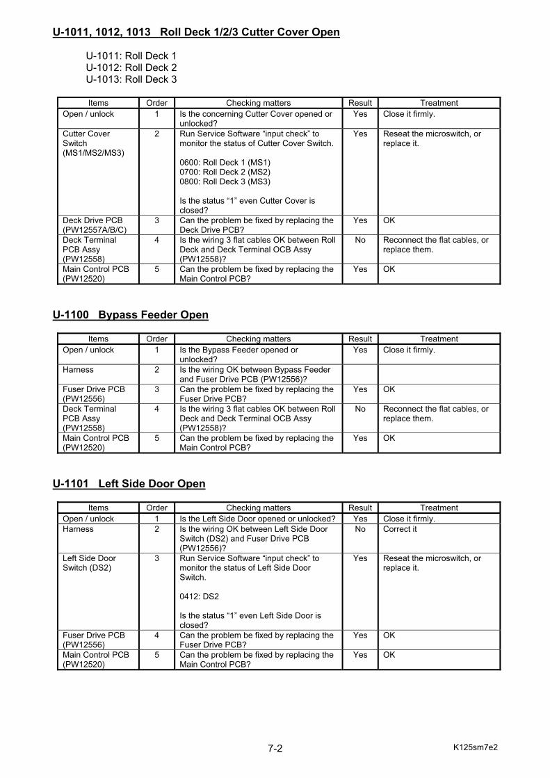
K125sm7e2 7-2
U-1011, 1012, 1013 Roll Deck 1/2/3 Cutter Cover Open U-1011: Roll Deck 1 U-1012: Roll Deck 2 U-1013: Roll Deck 3
Items Order Checking matters Result Treatment Open / unlock 1 Is the concerning Cutter Cover opened or
unlocked? Yes Close it firmly.
Cutter Cover Switch (MS1/MS2/MS3)
2 Run Service Software “input check” to monitor the status of Cutter Cover Switch. 0600: Roll Deck 1 (MS1) 0700: Roll Deck 2 (MS2) 0800: Roll Deck 3 (MS3) Is the status “1” even Cutter Cover is closed?
Yes Reseat the microswitch, or replace it.
Deck Drive PCB (PW12557A/B/C)
3 Can the problem be fixed by replacing the Deck Drive PCB?
Yes OK
Deck Terminal PCB Assy (PW12558)
4 Is the wiring 3 flat cables OK between Roll Deck and Deck Terminal OCB Assy (PW12558)?
No Reconnect the flat cables, or replace them.
Main Control PCB (PW12520)
5 Can the problem be fixed by replacing the Main Control PCB?
Yes OK
U-1100 Bypass Feeder Open
Items Order Checking matters Result Treatment Open / unlock 1 Is the Bypass Feeder opened or
unlocked? Yes Close it firmly.
Harness 2 Is the wiring OK between Bypass Feeder and Fuser Drive PCB (PW12556)?
Fuser Drive PCB (PW12556)
3 Can the problem be fixed by replacing the Fuser Drive PCB?
Yes OK
Deck Terminal PCB Assy (PW12558)
4 Is the wiring 3 flat cables OK between Roll Deck and Deck Terminal OCB Assy (PW12558)?
No Reconnect the flat cables, or replace them.
Main Control PCB (PW12520)
5 Can the problem be fixed by replacing the Main Control PCB?
Yes OK
U-1101 Left Side Door Open
Items Order Checking matters Result Treatment Open / unlock 1 Is the Left Side Door opened or unlocked? Yes Close it firmly. Harness 2 Is the wiring OK between Left Side Door
Switch (DS2) and Fuser Drive PCB (PW12556)?
No Correct it
Left Side Door Switch (DS2)
3 Run Service Software “input check” to monitor the status of Left Side Door Switch. 0412: DS2 Is the status “1” even Left Side Door is closed?
Yes Reseat the microswitch, or replace it.
Fuser Drive PCB (PW12556)
4 Can the problem be fixed by replacing the Fuser Drive PCB?
Yes OK
Main Control PCB (PW12520)
5 Can the problem be fixed by replacing the Main Control PCB?
Yes OK
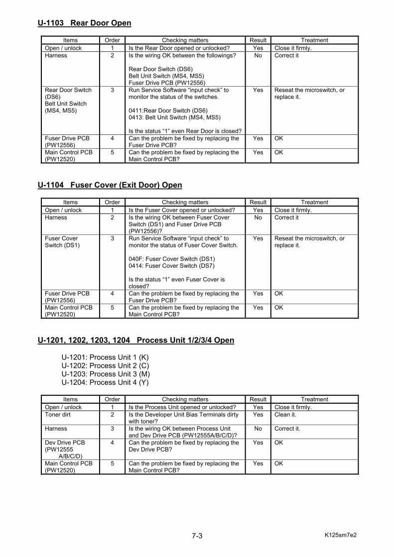
K125sm7e2 7-3
U-1103 Rear Door Open
Items Order Checking matters Result Treatment Open / unlock 1 Is the Rear Door opened or unlocked? Yes Close it firmly. Harness 2 Is the wiring OK between the followings?
Rear Door Switch (DS6) Belt Unit Switch (MS4, MS5) Fuser Drive PCB (PW12556)
No Correct it
Rear Door Switch (DS6) Belt Unit Switch (MS4, MS5)
3 Run Service Software “input check” to monitor the status of the switches. 0411:Rear Door Switch (DS6) 0413: Belt Unit Switch (MS4, MS5) Is the status “1” even Rear Door is closed?
Yes Reseat the microswitch, or replace it.
Fuser Drive PCB (PW12556)
4 Can the problem be fixed by replacing the Fuser Drive PCB?
Yes OK
Main Control PCB (PW12520)
5 Can the problem be fixed by replacing the Main Control PCB?
Yes OK
U-1104 Fuser Cover (Exit Door) Open
Items Order Checking matters Result Treatment Open / unlock 1 Is the Fuser Cover opened or unlocked? Yes Close it firmly. Harness 2 Is the wiring OK between Fuser Cover
Switch (DS1) and Fuser Drive PCB (PW12556)?
No Correct it
Fuser Cover Switch (DS1)
3 Run Service Software “input check” to monitor the status of Fuser Cover Switch. 040F: Fuser Cover Switch (DS1) 0414: Fuser Cover Switch (DS7) Is the status “1” even Fuser Cover is closed?
Yes Reseat the microswitch, or replace it.
Fuser Drive PCB (PW12556)
4 Can the problem be fixed by replacing the Fuser Drive PCB?
Yes OK
Main Control PCB (PW12520)
5 Can the problem be fixed by replacing the Main Control PCB?
Yes OK
U-1201, 1202, 1203, 1204 Process Unit 1/2/3/4 Open U-1201: Process Unit 1 (K) U-1202: Process Unit 2 (C) U-1203: Process Unit 3 (M) U-1204: Process Unit 4 (Y)
Items Order Checking matters Result Treatment Open / unlock 1 Is the Process Unit opened or unlocked? Yes Close it firmly. Toner dirt 2 Is the Developer Unit Bias Terminals dirty
with toner? Yes Clean it.
Harness 3 Is the wiring OK between Process Unit and Dev Drive PCB (PW12555A/B/C/D)?
No Correct it.
Dev Drive PCB (PW12555
A/B/C/D)
4 Can the problem be fixed by replacing the Dev Drive PCB?
Yes OK
Main Control PCB (PW12520)
5 Can the problem be fixed by replacing the Main Control PCB?
Yes OK
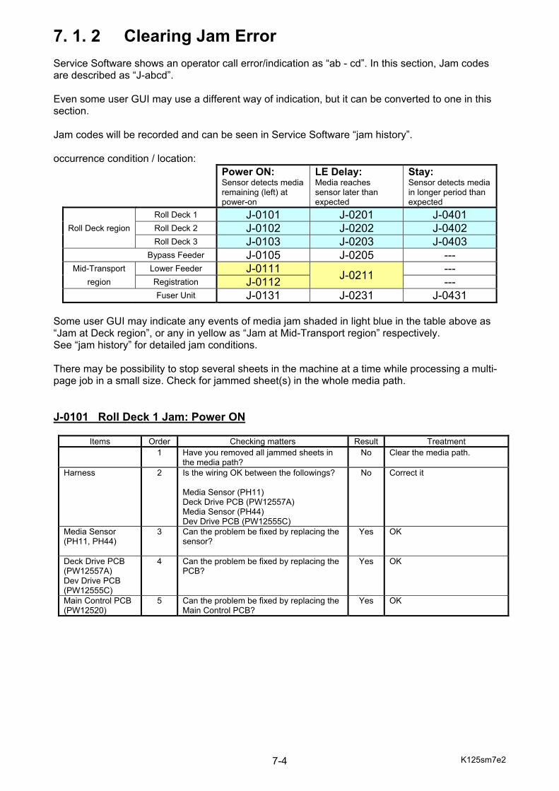
K125sm7e2 7-4
7. 1. 2 Clearing Jam Error Service Software shows an operator call error/indication as “ab - cd”. In this section, Jam codes are described as “J-abcd”. Even some user GUI may use a different way of indication, but it can be converted to one in this section. Jam codes will be recorded and can be seen in Service Software “jam history”. occurrence condition / location:
Power ON: Sensor detects media remaining (left) at power-on
LE Delay: Media reaches sensor later than expected
Stay: Sensor detects media in longer period than expected
Roll Deck 1 J-0101 J-0201 J-0401 Roll Deck region Roll Deck 2 J-0102 J-0202 J-0402
Roll Deck 3 J-0103 J-0203 J-0403 Bypass Feeder J-0105 J-0205 ---
Mid-Transport Lower Feeder J-0111 J-0211 --- region Registration J-0112 ---
Fuser Unit J-0131 J-0231 J-0431 Some user GUI may indicate any events of media jam shaded in light blue in the table above as “Jam at Deck region”, or any in yellow as “Jam at Mid-Transport region” respectively. See “jam history” for detailed jam conditions. There may be possibility to stop several sheets in the machine at a time while processing a multi-page job in a small size. Check for jammed sheet(s) in the whole media path. J-0101 Roll Deck 1 Jam: Power ON
Items Order Checking matters Result Treatment 1 Have you removed all jammed sheets in
the media path? No Clear the media path.
Harness 2 Is the wiring OK between the followings? Media Sensor (PH11) Deck Drive PCB (PW12557A) Media Sensor (PH44) Dev Drive PCB (PW12555C)
No Correct it
Media Sensor (PH11, PH44)
3 Can the problem be fixed by replacing the sensor?
Yes OK
Deck Drive PCB (PW12557A) Dev Drive PCB (PW12555C)
4 Can the problem be fixed by replacing the PCB?
Yes OK
Main Control PCB (PW12520)
5 Can the problem be fixed by replacing the Main Control PCB?
Yes OK
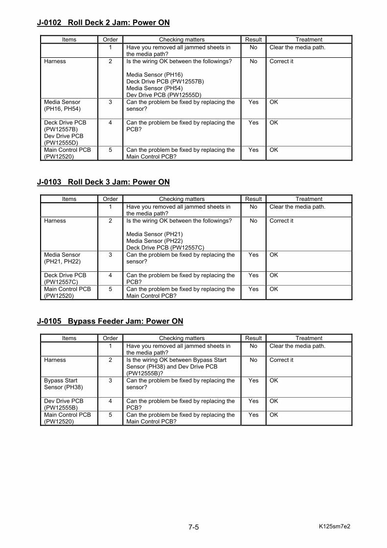
K125sm7e2 7-5
J-0102 Roll Deck 2 Jam: Power ON
Items Order Checking matters Result Treatment 1 Have you removed all jammed sheets in
the media path? No Clear the media path.
Harness 2 Is the wiring OK between the followings? Media Sensor (PH16) Deck Drive PCB (PW12557B) Media Sensor (PH54) Dev Drive PCB (PW12555D)
No Correct it
Media Sensor (PH16, PH54)
3 Can the problem be fixed by replacing the sensor?
Yes OK
Deck Drive PCB (PW12557B) Dev Drive PCB (PW12555D)
4 Can the problem be fixed by replacing the PCB?
Yes OK
Main Control PCB (PW12520)
5 Can the problem be fixed by replacing the Main Control PCB?
Yes OK
J-0103 Roll Deck 3 Jam: Power ON
Items Order Checking matters Result Treatment 1 Have you removed all jammed sheets in
the media path? No Clear the media path.
Harness 2 Is the wiring OK between the followings? Media Sensor (PH21) Media Sensor (PH22) Deck Drive PCB (PW12557C)
No Correct it
Media Sensor (PH21, PH22)
3 Can the problem be fixed by replacing the sensor?
Yes OK
Deck Drive PCB (PW12557C)
4 Can the problem be fixed by replacing the PCB?
Yes OK
Main Control PCB (PW12520)
5 Can the problem be fixed by replacing the Main Control PCB?
Yes OK
J-0105 Bypass Feeder Jam: Power ON
Items Order Checking matters Result Treatment 1 Have you removed all jammed sheets in
the media path? No Clear the media path.
Harness 2 Is the wiring OK between Bypass Start Sensor (PH38) and Dev Drive PCB (PW12555B)?
No Correct it
Bypass Start Sensor (PH38)
3 Can the problem be fixed by replacing the sensor?
Yes OK
Dev Drive PCB (PW12555B)
4 Can the problem be fixed by replacing the PCB?
Yes OK
Main Control PCB (PW12520)
5 Can the problem be fixed by replacing the Main Control PCB?
Yes OK
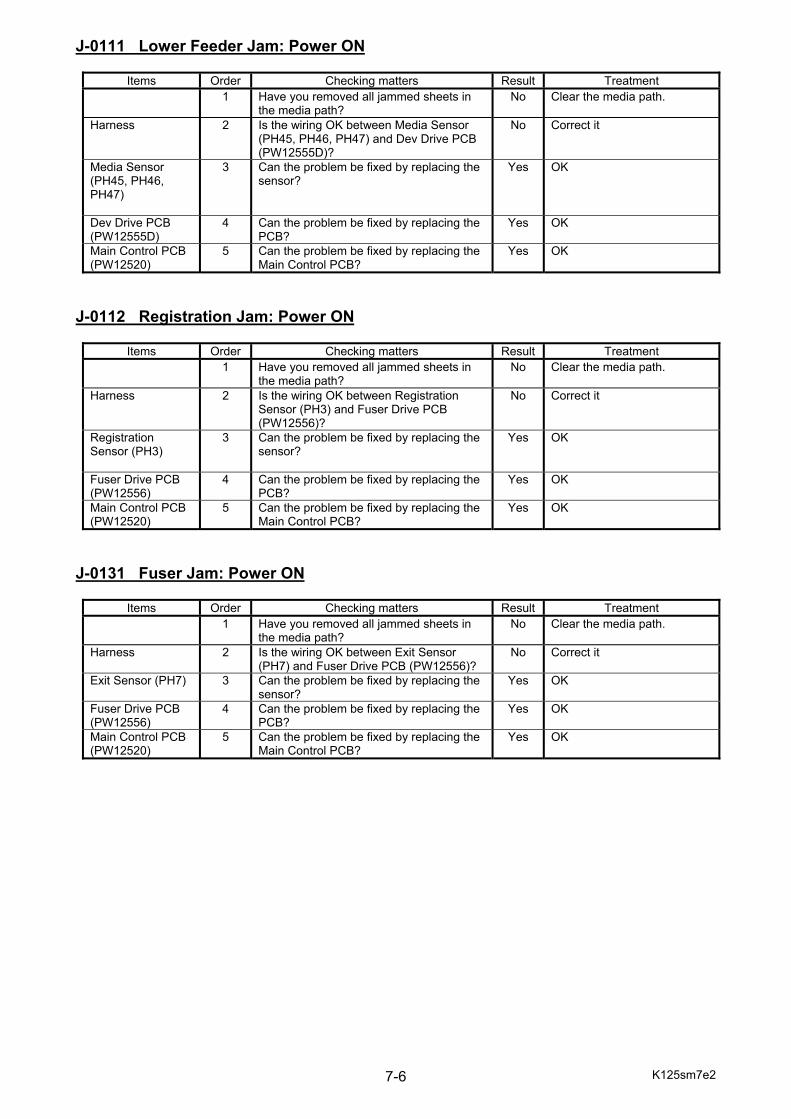
K125sm7e2 7-6
J-0111 Lower Feeder Jam: Power ON
Items Order Checking matters Result Treatment 1 Have you removed all jammed sheets in
the media path? No Clear the media path.
Harness 2 Is the wiring OK between Media Sensor (PH45, PH46, PH47) and Dev Drive PCB (PW12555D)?
No Correct it
Media Sensor (PH45, PH46, PH47)
3 Can the problem be fixed by replacing the sensor?
Yes OK
Dev Drive PCB (PW12555D)
4 Can the problem be fixed by replacing the PCB?
Yes OK
Main Control PCB (PW12520)
5 Can the problem be fixed by replacing the Main Control PCB?
Yes OK
J-0112 Registration Jam: Power ON
Items Order Checking matters Result Treatment 1 Have you removed all jammed sheets in
the media path? No Clear the media path.
Harness 2 Is the wiring OK between Registration Sensor (PH3) and Fuser Drive PCB (PW12556)?
No Correct it
Registration Sensor (PH3)
3 Can the problem be fixed by replacing the sensor?
Yes OK
Fuser Drive PCB (PW12556)
4 Can the problem be fixed by replacing the PCB?
Yes OK
Main Control PCB (PW12520)
5 Can the problem be fixed by replacing the Main Control PCB?
Yes OK
J-0131 Fuser Jam: Power ON
Items Order Checking matters Result Treatment 1 Have you removed all jammed sheets in
the media path? No Clear the media path.
Harness 2 Is the wiring OK between Exit Sensor (PH7) and Fuser Drive PCB (PW12556)?
No Correct it
Exit Sensor (PH7)
3 Can the problem be fixed by replacing the sensor?
Yes OK
Fuser Drive PCB (PW12556)
4 Can the problem be fixed by replacing the PCB?
Yes OK
Main Control PCB (PW12520)
5 Can the problem be fixed by replacing the Main Control PCB?
Yes OK
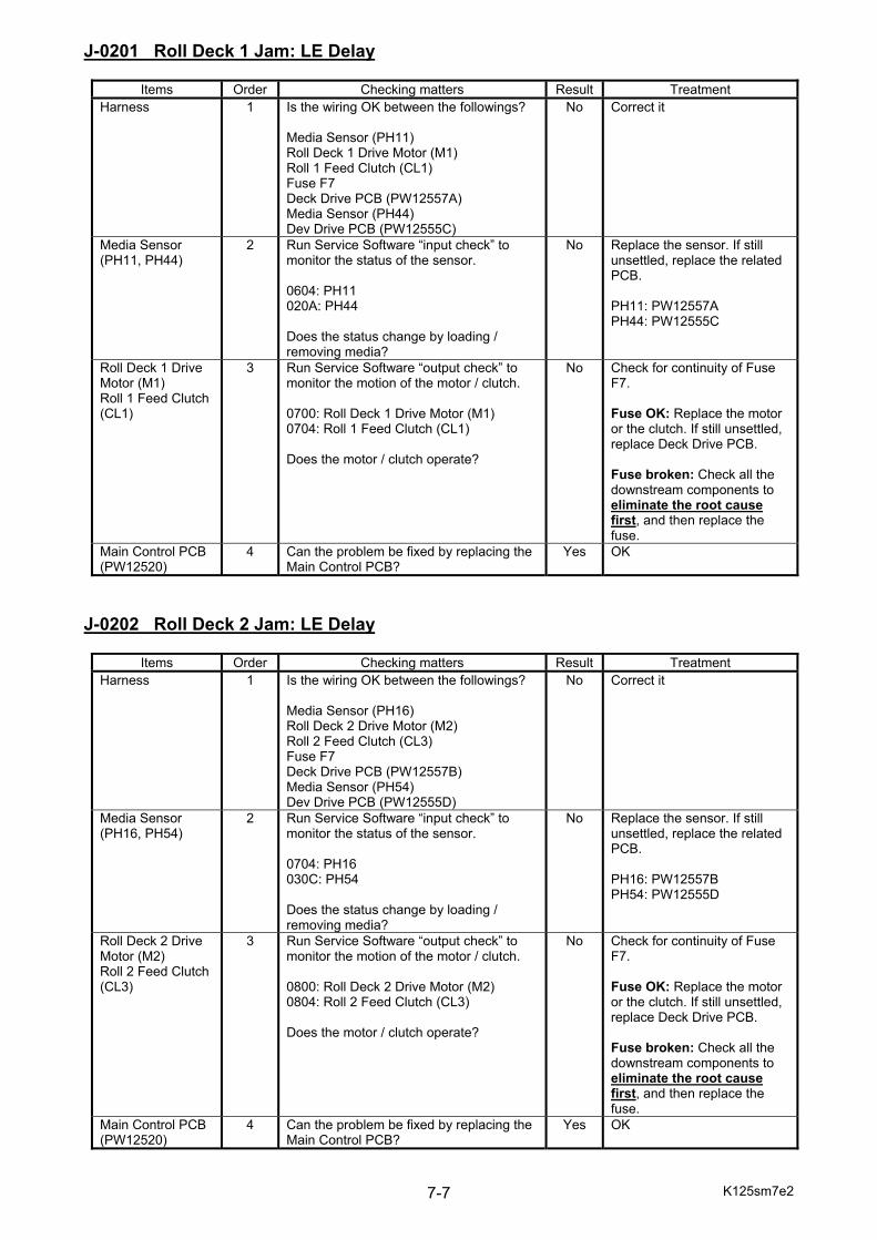
K125sm7e2 7-7
J-0201 Roll Deck 1 Jam: LE Delay
Items Order Checking matters Result Treatment Harness 1 Is the wiring OK between the followings?
Media Sensor (PH11) Roll Deck 1 Drive Motor (M1) Roll 1 Feed Clutch (CL1) Fuse F7 Deck Drive PCB (PW12557A) Media Sensor (PH44) Dev Drive PCB (PW12555C)
No Correct it
Media Sensor (PH11, PH44)
2 Run Service Software “input check” to monitor the status of the sensor. 0604: PH11 020A: PH44 Does the status change by loading / removing media?
No Replace the sensor. If still unsettled, replace the related PCB. PH11: PW12557A PH44: PW12555C
Roll Deck 1 Drive Motor (M1) Roll 1 Feed Clutch (CL1)
3 Run Service Software “output check” to monitor the motion of the motor / clutch. 0700: Roll Deck 1 Drive Motor (M1) 0704: Roll 1 Feed Clutch (CL1) Does the motor / clutch operate?
No Check for continuity of Fuse F7. Fuse OK: Replace the motor or the clutch. If still unsettled, replace Deck Drive PCB. Fuse broken: Check all the downstream components to eliminate the root cause first, and then replace the fuse.
Main Control PCB (PW12520)
4 Can the problem be fixed by replacing the Main Control PCB?
Yes OK
J-0202 Roll Deck 2 Jam: LE Delay
Items Order Checking matters Result Treatment Harness 1 Is the wiring OK between the followings?
Media Sensor (PH16) Roll Deck 2 Drive Motor (M2) Roll 2 Feed Clutch (CL3) Fuse F7 Deck Drive PCB (PW12557B) Media Sensor (PH54) Dev Drive PCB (PW12555D)
No Correct it
Media Sensor (PH16, PH54)
2 Run Service Software “input check” to monitor the status of the sensor. 0704: PH16 030C: PH54 Does the status change by loading / removing media?
No Replace the sensor. If still unsettled, replace the related PCB. PH16: PW12557B PH54: PW12555D
Roll Deck 2 Drive Motor (M2) Roll 2 Feed Clutch (CL3)
3 Run Service Software “output check” to monitor the motion of the motor / clutch. 0800: Roll Deck 2 Drive Motor (M2) 0804: Roll 2 Feed Clutch (CL3) Does the motor / clutch operate?
No Check for continuity of Fuse F7. Fuse OK: Replace the motor or the clutch. If still unsettled, replace Deck Drive PCB. Fuse broken: Check all the downstream components to eliminate the root cause first, and then replace the fuse.
Main Control PCB (PW12520)
4 Can the problem be fixed by replacing the Main Control PCB?
Yes OK
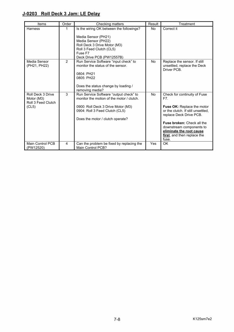
K125sm7e2 7-8
J-0203 Roll Deck 3 Jam: LE Delay
Items Order Checking matters Result Treatment Harness 1 Is the wiring OK between the followings?
Media Sensor (PH21) Media Sensor (PH22) Roll Deck 3 Drive Motor (M3) Roll 3 Feed Clutch (CL5) Fuse F7 Deck Drive PCB (PW12557B)
No Correct it
Media Sensor (PH21, PH22)
2 Run Service Software “input check” to monitor the status of the sensor. 0804: PH21 0805: PH22 Does the status change by loading / removing media?
No Replace the sensor. If still unsettled, replace the Deck Driver PCB.
Roll Deck 3 Drive Motor (M3) Roll 3 Feed Clutch (CL5)
3 Run Service Software “output check” to monitor the motion of the motor / clutch. 0900: Roll Deck 3 Drive Motor (M3) 0904: Roll 3 Feed Clutch (CL5) Does the motor / clutch operate?
No Check for continuity of Fuse F7. Fuse OK: Replace the motor or the clutch. If still unsettled, replace Deck Drive PCB. Fuse broken: Check all the downstream components to eliminate the root cause first, and then replace the fuse.
Main Control PCB (PW12520)
4 Can the problem be fixed by replacing the Main Control PCB?
Yes OK
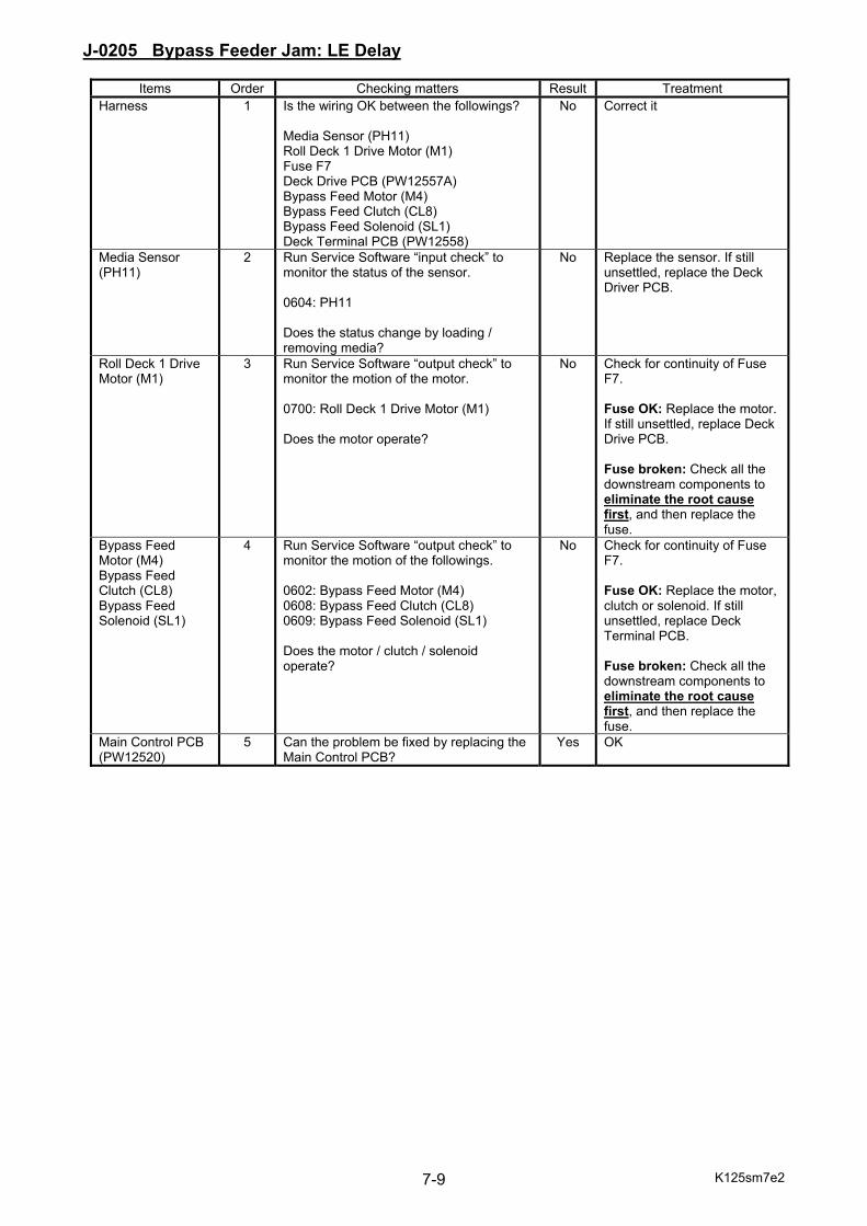
K125sm7e2 7-9
J-0205 Bypass Feeder Jam: LE Delay
Items Order Checking matters Result Treatment Harness 1 Is the wiring OK between the followings?
Media Sensor (PH11) Roll Deck 1 Drive Motor (M1) Fuse F7 Deck Drive PCB (PW12557A) Bypass Feed Motor (M4) Bypass Feed Clutch (CL8) Bypass Feed Solenoid (SL1) Deck Terminal PCB (PW12558)
No Correct it
Media Sensor (PH11)
2 Run Service Software “input check” to monitor the status of the sensor. 0604: PH11 Does the status change by loading / removing media?
No Replace the sensor. If still unsettled, replace the Deck Driver PCB.
Roll Deck 1 Drive Motor (M1)
3 Run Service Software “output check” to monitor the motion of the motor. 0700: Roll Deck 1 Drive Motor (M1) Does the motor operate?
No Check for continuity of Fuse F7. Fuse OK: Replace the motor. If still unsettled, replace Deck Drive PCB. Fuse broken: Check all the downstream components to eliminate the root cause first, and then replace the fuse.
Bypass Feed Motor (M4) Bypass Feed Clutch (CL8) Bypass Feed Solenoid (SL1)
4 Run Service Software “output check” to monitor the motion of the followings. 0602: Bypass Feed Motor (M4) 0608: Bypass Feed Clutch (CL8) 0609: Bypass Feed Solenoid (SL1) Does the motor / clutch / solenoid operate?
No Check for continuity of Fuse F7. Fuse OK: Replace the motor, clutch or solenoid. If still unsettled, replace Deck Terminal PCB. Fuse broken: Check all the downstream components to eliminate the root cause first, and then replace the fuse.
Main Control PCB (PW12520)
5 Can the problem be fixed by replacing the Main Control PCB?
Yes OK

K125sm7e2 7-10
J-0211 Lower Feeder Jam: LE Delay
Items Order Checking matters Result Treatment Harness 1 Is the wiring OK between the followings?
Media Sensor (PH46, PH47) Fuse F7 Dev Drive PCB (PW12555D) Registration Sensor (PH3) Fuser Drive PCB (PW12556) Lower Feeder Motor (M5) Lower Feeder Clutch (CL9) Deck Terminal PCB (PW12558)
No Correct it
Media Sensor (PH46, PH47)
2 Run Service Software “input check” to monitor the status of the sensor. 030E: PH46 030F: PH47 Does the status change by loading / removing media?
No Replace the sensor. If still unsettled, replace the Dev Driver PCB.
Registration Sensor (PH3)
3 Run Service Software “input check” to monitor the status of the sensor. 0404: PH3 Does the status change by loading / removing media?
No Replace the sensor. If still unsettled, replace the Fuser Driver PCB.
Lower Feeder Motor (M5) Lower Feeder Clutch (CL9)
4 Run Service Software “output check” to monitor the motion of the motor / clutch. 0600: Lower Feeder Motor (M5) 0607: Lower Feeder Clutch (CL9) Does the motor / clutch operate?
No Check for continuity of Fuse F7. Fuse OK: Replace the motor or the clutch. If still unsettled, replace Deck Terminal PCB. Fuse broken: Check all the downstream components to eliminate the root cause first, and then replace the fuse.
Main Control PCB (PW12520)
5 Can the problem be fixed by replacing the Main Control PCB?
Yes OK

K125sm7e2 7-11
J-0231 Fuser Jam: LE Delay
Items Order Checking matters Result Treatment Harness 1 Is the wiring OK between the followings?
Exit Sensor (PH7) Belt Unit Drive Motor (M6) Fuser Motor (M11) Fuse F5 Fuser Drive PCB (PW12556)
No Correct it
Exit Sensor (PH7)
2 Run Service Software “input check” to monitor the status of the sensor. 0409: PH7 Does the status change by loading / removing media?
No Replace the sensor. If still unsettled, replace the Fuser Driver PCB.
Belt Unit Drive Motor (M6)
4 Run Service Software “output check” to monitor the motion of the motor. 0500: Belt Unit Drive Motor (M6) Does the motor operate?
No Check for continuity of Fuse F5. Fuse OK: Replace the motor. If still unsettled, replace Fuser Drive PCB. Fuse broken: Check all the downstream components to eliminate the root cause first, and then replace the fuse.
Fuser Motor (M11) 4 Run Service Software “output check” to monitor the motion of the motor. 0501: Fuser Motor (M11) Does the motor operate?
No Check for continuity of Fuse F7. Fuse OK: Replace the motor. If still unsettled, replace Fuser Drive PCB. Fuse broken: Check all the downstream components to eliminate the root cause first, and then replace the fuse.
Main Control PCB (PW12520)
5 Can the problem be fixed by replacing the Main Control PCB?
Yes OK

K125sm7e2 7-12
J-0401 Roll Deck 1 Jam: Stay
Items Order Checking matters Result Treatment Harness 1 Is the wiring OK between the followings?
Roll 1 Standby Sensor (PH10) Roll Deck 1 Drive Motor (M1) Roll 1 Reverse Clutch (CL2) Fuse F7 Deck Drive PCB (PW12557A)
No Correct it
Roll 1 Standby Sensor (PH10)
2 Run Service Software “input check” to monitor the status of the sensor. 0603: PH10 Does the status change by loading / removing media?
No Replace the sensor. If still unsettled, replace Deck Drive PCB.
Roll Deck 1 Drive Motor (M1) Roll 1 Reverse Clutch (CL2)
3 Run Service Software “output check” to monitor the motion of the motor / clutch. 0700: Roll Deck 1 Drive Motor (M1) 0705: Roll 1 Reverse Clutch (CL2) Does the motor / clutch operate?
No Check for continuity of Fuse F7. Fuse OK: Replace the motor or the clutch. If still unsettled, replace Deck Drive PCB. Fuse broken: Check all the downstream components to eliminate the root cause first, and then replace the fuse.
Main Control PCB (PW12520)
4 Can the problem be fixed by replacing the Main Control PCB?
Yes OK
J-0402 Roll Deck 2 Jam: Stay
Items Order Checking matters Result Treatment Harness 1 Is the wiring OK between the followings?
Roll 2 Standby Sensor (PH15) Roll Deck 2 Drive Motor (M2) Roll 2 Reverse Clutch (CL4) Fuse F7 Deck Drive PCB (PW12557B)
No Correct it
Roll 2 Standby Sensor (PH15)
2 Run Service Software “input check” to monitor the status of the sensor. 0703: PH15 Does the status change by loading / removing media?
No Replace the sensor. If still unsettled, replace Deck Drive PCB.
Roll Deck 2 Drive Motor (M2) Roll 2 Reverse Clutch (CL4)
3 Run Service Software “output check” to monitor the motion of the motor / clutch. 0800: Roll Deck 2 Drive Motor (M2) 0805: Roll 2 Reverse Clutch (CL4) Does the motor / clutch operate?
No Check for continuity of Fuse F7. Fuse OK: Replace the motor or the clutch. If still unsettled, replace Deck Drive PCB. Fuse broken: Check all the downstream components to eliminate the root cause first, and then replace the fuse.
Main Control PCB (PW12520)
4 Can the problem be fixed by replacing the Main Control PCB?
Yes OK

K125sm7e2 7-13
J-0403 Roll Deck 3 Jam: Stay
Items Order Checking matters Result Treatment Harness 1 Is the wiring OK between the followings?
Roll 3 Standby Sensor (PH20) Roll Deck 3 Drive Motor (M3) Roll 3 Reverse Clutch (CL6) Fuse F7 Deck Drive PCB (PW12557C)
No Correct it
Roll 3 Standby Sensor (PH20)
2 Run Service Software “input check” to monitor the status of the sensor. 0803: PH20 Does the status change by loading / removing media?
No Replace the sensor. If still unsettled, replace Deck Drive PCB.
Roll Deck 3 Drive Motor (M3) Roll 3 Reverse Clutch (CL6)
3 Run Service Software “output check” to monitor the motion of the motor / clutch. 0900: Roll Deck 3 Drive Motor (M3) 0905: Roll 3 Reverse Clutch (CL6) Does the motor / clutch operate?
No Check for continuity of Fuse F7. Fuse OK: Replace the motor or the clutch. If still unsettled, replace Deck Drive PCB. Fuse broken: Check all the downstream components to eliminate the root cause first, and then replace the fuse.
Main Control PCB (PW12520)
4 Can the problem be fixed by replacing the Main Control PCB?
Yes OK
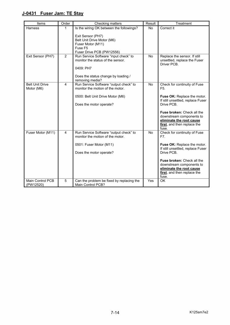
K125sm7e2 7-14
J-0431 Fuser Jam: TE Stay
Items Order Checking matters Result Treatment Harness 1 Is the wiring OK between the followings?
Exit Sensor (PH7) Belt Unit Drive Motor (M6) Fuser Motor (M11) Fuse F5 Fuser Drive PCB (PW12556)
No Correct it
Exit Sensor (PH7)
2 Run Service Software “input check” to monitor the status of the sensor. 0409: PH7 Does the status change by loading / removing media?
No Replace the sensor. If still unsettled, replace the Fuser Driver PCB.
Belt Unit Drive Motor (M6)
4 Run Service Software “output check” to monitor the motion of the motor. 0500: Belt Unit Drive Motor (M6) Does the motor operate?
No Check for continuity of Fuse F5. Fuse OK: Replace the motor. If still unsettled, replace Fuser Drive PCB. Fuse broken: Check all the downstream components to eliminate the root cause first, and then replace the fuse.
Fuser Motor (M11) 4 Run Service Software “output check” to monitor the motion of the motor. 0501: Fuser Motor (M11) Does the motor operate?
No Check for continuity of Fuse F7. Fuse OK: Replace the motor. If still unsettled, replace Fuser Drive PCB. Fuse broken: Check all the downstream components to eliminate the root cause first, and then replace the fuse.
Main Control PCB (PW12520)
5 Can the problem be fixed by replacing the Main Control PCB?
Yes OK
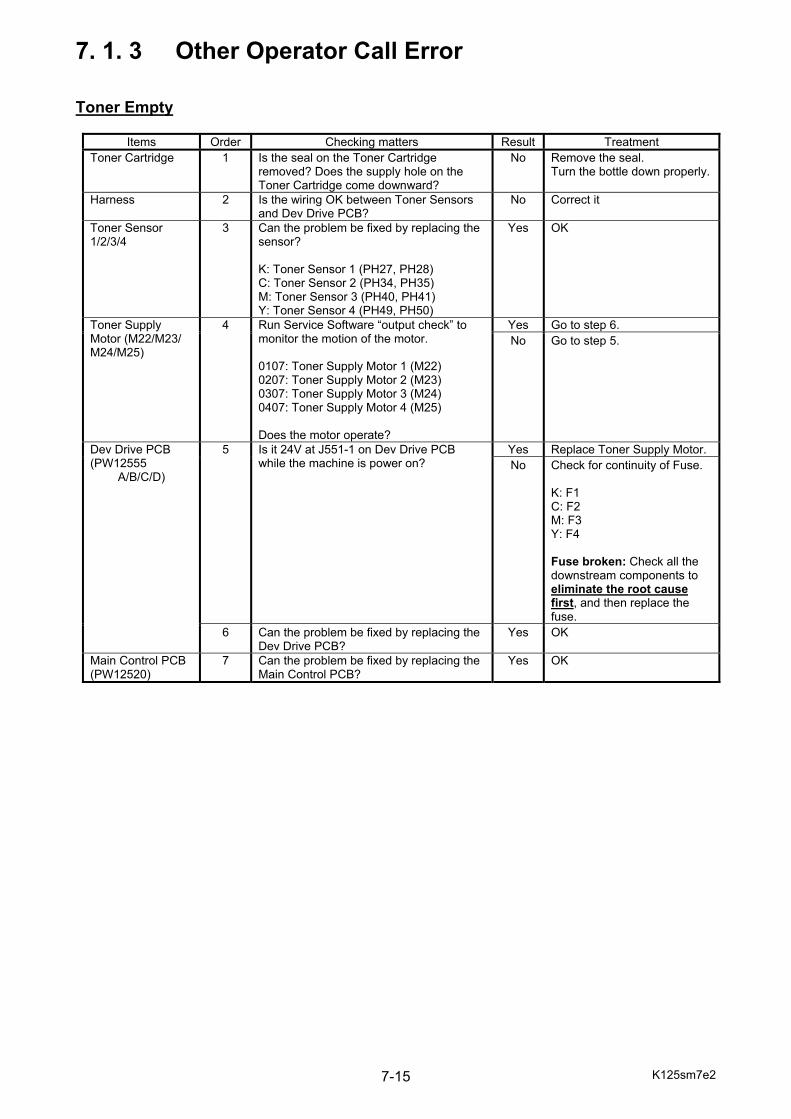
K125sm7e2 7-15
7. 1. 3 Other Operator Call Error Toner Empty
Items Order Checking matters Result Treatment Toner Cartridge 1 Is the seal on the Toner Cartridge
removed? Does the supply hole on the Toner Cartridge come downward?
No Remove the seal. Turn the bottle down properly.
Harness 2 Is the wiring OK between Toner Sensors and Dev Drive PCB?
No Correct it
Toner Sensor 1/2/3/4
3 Can the problem be fixed by replacing the sensor? K: Toner Sensor 1 (PH27, PH28) C: Toner Sensor 2 (PH34, PH35) M: Toner Sensor 3 (PH40, PH41) Y: Toner Sensor 4 (PH49, PH50)
Yes OK
Toner Supply Motor (M22/M23/ M24/M25)
4 Run Service Software “output check” to monitor the motion of the motor. 0107: Toner Supply Motor 1 (M22) 0207: Toner Supply Motor 2 (M23) 0307: Toner Supply Motor 3 (M24) 0407: Toner Supply Motor 4 (M25) Does the motor operate?
Yes Go to step 6. No Go to step 5.
Dev Drive PCB (PW12555
A/B/C/D)
5 Is it 24V at J551-1 on Dev Drive PCB while the machine is power on?
Yes Replace Toner Supply Motor.No Check for continuity of Fuse.
K: F1 C: F2 M: F3 Y: F4 Fuse broken: Check all the downstream components to eliminate the root cause first, and then replace the fuse.
6 Can the problem be fixed by replacing the Dev Drive PCB?
Yes OK
Main Control PCB (PW12520)
7 Can the problem be fixed by replacing the Main Control PCB?
Yes OK
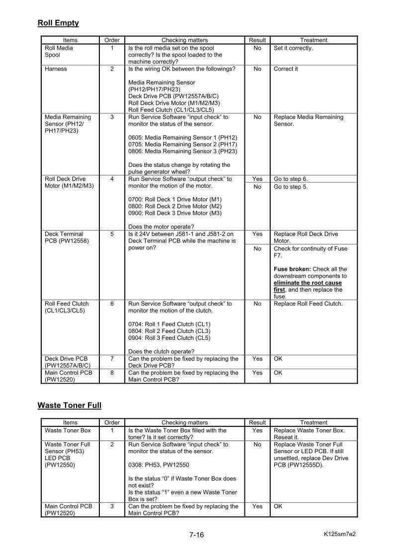
K125sm7e2 7-16
Roll Empty
Items Order Checking matters Result Treatment Roll Media Spool
1 Is the roll media set on the spool correctly? Is the spool loaded to the machine correctly?
No Set it correctly.
Harness 2 Is the wiring OK between the followings? Media Remaining Sensor (PH12/PH17/PH23) Deck Drive PCB (PW12557A/B/C) Roll Deck Drive Motor (M1/M2/M3) Roll Feed Clutch (CL1/CL3/CL5)
No Correct it
Media Remaining Sensor (PH12/ PH17/PH23)
3 Run Service Software “input check” to monitor the status of the sensor. 0605: Media Remaining Sensor 1 (PH12) 0705: Media Remaining Sensor 2 (PH17) 0806: Media Remaining Sensor 3 (PH23) Does the status change by rotating the pulse generator wheel?
No Replace Media Remaining Sensor.
Roll Deck Drive Motor (M1/M2/M3)
4
Run Service Software “output check” to monitor the motion of the motor. 0700: Roll Deck 1 Drive Motor (M1) 0800: Roll Deck 2 Drive Motor (M2) 0900: Roll Deck 3 Drive Motor (M3) Does the motor operate?
Yes Go to step 6. No Go to step 5.
Deck Terminal PCB (PW12558)
5
Is it 24V between J581-1 and J581-2 on Deck Terminal PCB while the machine is power on?
Yes Replace Roll Deck Drive Motor.
No Check for continuity of Fuse F7. Fuse broken: Check all the downstream components to eliminate the root cause first, and then replace the fuse.
Roll Feed Clutch (CL1/CL3/CL5)
6 Run Service Software “output check” to monitor the motion of the clutch. 0704: Roll 1 Feed Clutch (CL1) 0804: Roll 2 Feed Clutch (CL3) 0904: Roll 3 Feed Clutch (CL5) Does the clutch operate?
No Replace Roll Feed Clutch.
Deck Drive PCB (PW12557A/B/C)
7 Can the problem be fixed by replacing the Deck Drive PCB?
Yes OK
Main Control PCB (PW12520)
8 Can the problem be fixed by replacing the Main Control PCB?
Yes OK
Waste Toner Full
Items Order Checking matters Result Treatment Waste Toner Box 1 Is the Waste Toner Box filled with the
toner? Is it set correctly? Yes Replace Waste Toner Box.
Reseat it. Waste Toner Full Sensor (PH53) LED PCB (PW12550)
2 Run Service Software “input check” to monitor the status of the sensor. 0308: PH53, PW12550 Is the status “0” if Waste Toner Box does not exist? Is the status “1” even a new Waste Toner Box is set?
No Replace Waste Toner Full Sensor or LED PCB. If still unsettled, replace Dev Drive PCB (PW12555D).
Main Control PCB (PW12520)
3 Can the problem be fixed by replacing the Main Control PCB?
Yes OK
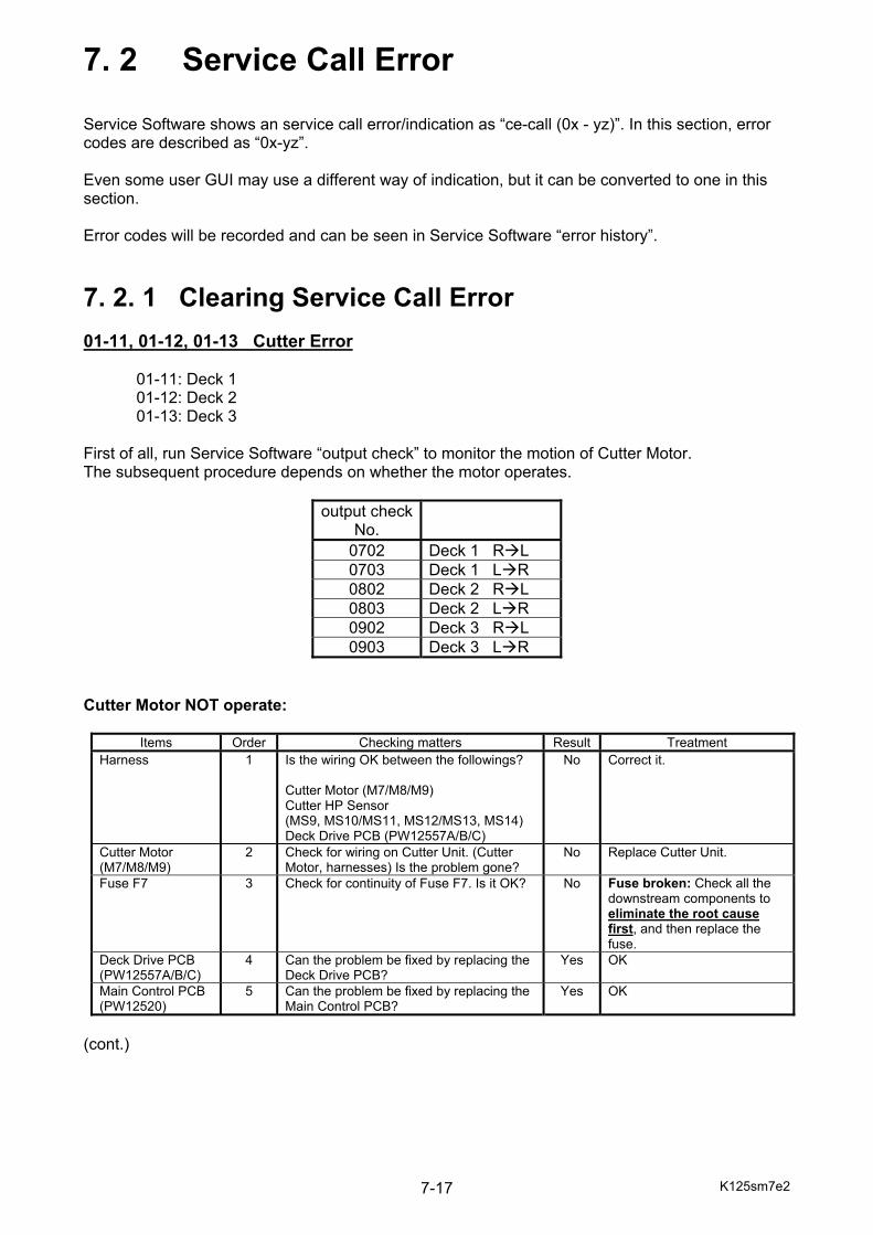
K125sm7e2 7-17
7. 2 Service Call Error Service Software shows an service call error/indication as “ce-call (0x - yz)”. In this section, error codes are described as “0x-yz”. Even some user GUI may use a different way of indication, but it can be converted to one in this section. Error codes will be recorded and can be seen in Service Software “error history”.
7. 2. 1 Clearing Service Call Error 01-11, 01-12, 01-13 Cutter Error 01-11: Deck 1 01-12: Deck 2 01-13: Deck 3 First of all, run Service Software “output check” to monitor the motion of Cutter Motor. The subsequent procedure depends on whether the motor operates.
output checkNo.
0702 Deck 1 R L 0703 Deck 1 L R 0802 Deck 2 R L 0803 Deck 2 L R 0902 Deck 3 R L 0903 Deck 3 L R
Cutter Motor NOT operate:
Items Order Checking matters Result Treatment Harness 1 Is the wiring OK between the followings?
Cutter Motor (M7/M8/M9) Cutter HP Sensor (MS9, MS10/MS11, MS12/MS13, MS14) Deck Drive PCB (PW12557A/B/C)
No Correct it.
Cutter Motor (M7/M8/M9)
2 Check for wiring on Cutter Unit. (Cutter Motor, harnesses) Is the problem gone?
No Replace Cutter Unit.
Fuse F7 3 Check for continuity of Fuse F7. Is it OK? No Fuse broken: Check all the downstream components to eliminate the root cause first, and then replace the fuse.
Deck Drive PCB (PW12557A/B/C)
4 Can the problem be fixed by replacing the Deck Drive PCB?
Yes OK
Main Control PCB (PW12520)
5 Can the problem be fixed by replacing the Main Control PCB?
Yes OK
(cont.)
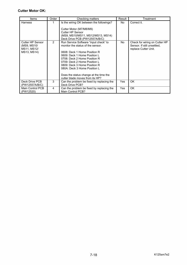
K125sm7e2 7-18
Cutter Motor OK:
Items Order Checking matters Result Treatment Harness 1 Is the wiring OK between the followings?
Cutter Motor (M7/M8/M9) Cutter HP Sensor (MS9, MS10/MS11, MS12/MS13, MS14) Deck Drive PCB (PW12557A/B/C)
No Correct it.
Cutter HP Sensor (MS9, MS10/ MS11, MS12/ MS13, MS14)
2 Run Service Software “input check” to monitor the status of the sensor. 0608: Deck 1 Home Position R 0609: Deck 1 Home Position L 0708: Deck 2 Home Position R 0709: Deck 2 Home Position L 0809: Deck 3 Home Position R 080A: Deck 3 Home Position L Does the status change at the time the cutter blade moves from its HP?
No Check for wiring on Cutter HP Sensor. If still unsettled, replace Cutter Unit.
Deck Drive PCB (PW12557A/B/C)
3 Can the problem be fixed by replacing the Deck Drive PCB?
Yes OK
Main Control PCB (PW12520)
4 Can the problem be fixed by replacing the Main Control PCB?
Yes OK

K125sm7e2 7-19
03-01 Dev Press Motor 1 Error First of all, run Service Software “output check” No.010B to monitor the motion of Dev Press Motor 1. The subsequent procedure depends on whether the motor operates. Dev Press Motor 1 NOT operate:
Items Order Checking matters Result Treatment Harness 1 Is the wiring OK between the followings?
Dev Press Motor 1 (M18) Dev Drive PCB (PW12555A) Fuse F1
No Correct it.
Dev Press Motor 1 (M18) Dev Drive PCB (PW12555A)
2 Can the problem be fixed by replacing Dev Press Motor or Dev Drive PCB?
Yes OK
Fuse F1 3 Check for continuity of Fuse F1. Is it OK? No Fuse broken: Check all the downstream components to eliminate the root cause first, and then replace the fuse.
Main Control PCB (PW12520)
4 Can the problem be fixed by replacing the Main Control PCB?
Yes OK
Dev Press Motor 1 OK:
Items Order Checking matters Result Treatment Harness 1 Is the wiring OK between Dev Press
Sensor (PH26) and Dev Drive PCB (PW12555A)?
No Correct it.
Dev Press Sensor (PH26)
2 Can the problem be fixed by replacing Dev Press Sensor?
Yes OK
Dev Drive PCB (PW12555A)
3 Can the problem be fixed by replacing Dev Drive PCB?
Yes OK
Main Control PCB (PW12520)
4 Can the problem be fixed by replacing the Main Control PCB?
Yes OK
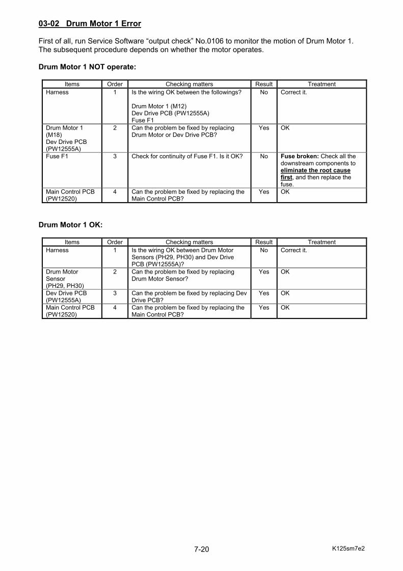
K125sm7e2 7-20
03-02 Drum Motor 1 Error First of all, run Service Software “output check” No.0106 to monitor the motion of Drum Motor 1. The subsequent procedure depends on whether the motor operates. Drum Motor 1 NOT operate:
Items Order Checking matters Result Treatment Harness 1 Is the wiring OK between the followings?
Drum Motor 1 (M12) Dev Drive PCB (PW12555A) Fuse F1
No Correct it.
Drum Motor 1 (M18) Dev Drive PCB (PW12555A)
2 Can the problem be fixed by replacing Drum Motor or Dev Drive PCB?
Yes OK
Fuse F1 3 Check for continuity of Fuse F1. Is it OK? No Fuse broken: Check all the downstream components to eliminate the root cause first, and then replace the fuse.
Main Control PCB (PW12520)
4 Can the problem be fixed by replacing the Main Control PCB?
Yes OK
Drum Motor 1 OK:
Items Order Checking matters Result Treatment Harness 1 Is the wiring OK between Drum Motor
Sensors (PH29, PH30) and Dev Drive PCB (PW12555A)?
No Correct it.
Drum Motor Sensor (PH29, PH30)
2 Can the problem be fixed by replacing Drum Motor Sensor?
Yes OK
Dev Drive PCB (PW12555A)
3 Can the problem be fixed by replacing Dev Drive PCB?
Yes OK
Main Control PCB (PW12520)
4 Can the problem be fixed by replacing the Main Control PCB?
Yes OK

K125sm7e2 7-21
03-20 Image Corona 1 Output Error
Items Order Checking matters Result Treatment Harness 1 Is the wiring OK between HV Power
Supply PCB 1 (HVP1) and Dev Drive PCB (PW12555A)?
No Correct it.
HV1 Harness Image Corona Wire
2 Is there any resistance between HV1 harness on HVP1 and the ground?
No Check HV1 harness and Image Corona Wire.
HV Power Supply PCB 1 (HVP1)
3 Can the problem be fixed by replacing the HV Power Supply PCB 1?
Yes OK
Dev Drive PCB (PW12555A)
4 Can the problem be fixed by replacing the Dev Drive PCB?
Yes OK
Main Control PCB (PW12520)
5 Can the problem be fixed by replacing the Main Control PCB?
Yes OK
03-21 Transfer Roller Bias 1 Output Error
Items Order Checking matters Result Treatment Harness 1 Is the wiring OK between HV Power
Supply PCB 1 (HVP1) and Dev Drive PCB (PW12555A)?
No Correct it.
HV1 Harness Transfer Roller 1
2 Is there any resistance between HV2 harness on HVP1 and the ground?
No Check HV2 harness and Transfer Roller.
TR M Lead 3 Is the harness CP23 correctly connected to the CP23 terminal on the HV Power Supply PCB?
No Connect it correctly.
4 Does the TR M Lead has any abnormality such as physical damage?
Yes Replace the TR M Lead.
HV Power Supply PCB 1 (HVP1)
5 Can the problem be fixed by replacing the HV Power Supply PCB 1?
Yes OK
Dev Drive PCB (PW12555A)
6 Can the problem be fixed by replacing the Dev Drive PCB?
Yes OK
Main Control PCB (PW12520)
7 Can the problem be fixed by replacing the Main Control PCB?
Yes OK
03-23 Developer Bias 1 Output Error
Items Order Checking matters Result Treatment Harness 1 Is the wiring OK between HV Power
Supply PCB 1 (HVP1) and Dev Drive PCB (PW12555A)?
No Correct it.
HV1 Harness Developer Unit (K)
2 Is there any resistance between OUT2 harness on HVP1 and the ground?
No Check OUT2 harness and Developer Unit.
HV Power Supply PCB 1 (HVP1)
3 Can the problem be fixed by replacing the HV Power Supply PCB 1?
Yes OK
Dev Drive PCB (PW12555A)
4 Can the problem be fixed by replacing the Dev Drive PCB?
Yes OK
Main Control PCB (PW12520)
5 Can the problem be fixed by replacing the Main Control PCB?
Yes OK

K125sm7e2 7-22
03-30, 03-31, 03-32 LED Head 1 Error 03-30: Head Array 1 03-31: Head Array 2 03-32: Head Array 3
Items Order Checking matters Result Treatment Harness 1 Is the wiring OK between the followings?
LED Head 1 (K) LED Terminal PCB (PW12521A) Main Control PCB (PW12520)
No Correct it.
LED Head LED Terminal PCB (PW12521A) Signal Cable
2 Can the problem be fixed by replacing LED Head, LED Terminal PCB or Signal Cable?
Yes OK
Fuse F9 3 Check for continuity of Fuse F9. Is it OK? No Fuse broken: Check all the downstream components to eliminate the root cause first, and then replace the fuse.
Main Control PCB (PW12520)
4 Can the problem be fixed by replacing the Main Control PCB?
Yes OK
03-36 Density Control 1 Error
Items Order Checking matters Result Treatment Toner Density Sensor (PH56) LED Head (K)
1 Does Toner Density Sensor or LED Head have toner dirt?
Yes Dust it off.
Harness 2 Is the wiring OK between Toner Density Sensor and Fuser Drive PCB (PW12556)?
No Correct it.
Toner Density Sensor (PH56)
3 Can the problem be fixed by replacing Density Sensor?
Yes OK
Fuser Drive PCB (PW12556)
4 Can the problem be fixed by replacing the Fuser Drive PCB?
Yes OK
Main Control PCB (PW12520)
5 Can the problem be fixed by replacing the Main Control PCB?
Yes OK

K125sm7e2 7-23
03-40 Wire Cleaning Motor 1 Error First of all, run Service Software “output check” to monitor the motion of Wire Cleaning Motor 1. The subsequent procedure depends on whether the motor operates.
output check No.
0109 Wire Cleaning Motor 1 R L 010A Wire Cleaning Motor 1 L R
Wire Cleaning Motor 1 NOT operate:
Items Order Checking matters Result Treatment Harness 1 Is the wiring OK between the followings?
Wire Cleaning Motor 1 (M27) Dev Drive PCB (PW12555A) Fuse F1
No Correct it.
Screw Shaft of Cleaning Pad
2 Does the screw shaft of Cleaning Pad have dirt or distortion?
Yes Clean or replace the screw shaft.
Wire Cleaning Motor 1 (M27) Dev Drive PCB (PW12555A)
Can the problem be fixed by replacing Wire Cleaning Motor or Dev Drive PCB?
Yes OK
Fuse F1 Check for continuity of Fuse F1. Is it OK? No Fuse broken: Check all the downstream components to eliminate the root cause first, and then replace the fuse.
Main Control PCB (PW12520)
Can the problem be fixed by replacing the Main Control PCB?
Yes OK
(cont.)
NOTE Wire Cleaning Motor Error and Cleaning Pad Home Position are NOT detected while operating “output check”. This means there is no “safety brake” to prevent Wire Cleaning Motor from operating even the Cleaning Pad reaches its home position (screw end). To avoid over current (overheat) on Wire Cleaning Motor, 1. Move Cleaning Pad in the middle of the corona unit by hand. 2. Stop the operation before it reaches the home position with noting its movement direction.

K125sm7e2 7-24
Wire Cleaning Motor 1 OK:
Items Order Checking matters Result Treatment Harness 1 Is the wiring OK between the followings?
Cleaning Pad 1 HP Sensor (MS15, MS19)Dev Drive PCB (PW12555A) Deck Terminal PCB (PW12558)
No Correct it.
Screw Shaft of Cleaning Pad
2 Does the screw shaft of Cleaning Pad have dirt or distortion?
Yes Clean or replace the screw shaft.
Cleaning Pad 1 HP Sensor R (MS19)
3 Draw out 1st Charging Unit (K). Rotate the screw to move Cleaning Pad to its HP R by hand. Reinstall the unit in the machine. Run Service Software “input check” to monitor the status of the switch. 0000: Cleaning Pad 1 HP R Is the status “1” with the unit installed? Is the status “0” if the unit is removed?
No Replace the microswitch.
Cleaning Pad 1 HP Sensor L (MS15)
4 Draw out 1st Charging Unit (K). Rotate the screw to move Cleaning Pad to its HP L by hand. Reinstall the unit in the machine. Run Service Software “input check” to monitor the status of the switch. 0503: Cleaning Pad 1 HP L Is the status “1” with the unit installed? Is the status “0” if the unit is removed?
No Replace the microswitch.
Dev Drive PCB (PW12555A)
5 Can the problem be fixed by replacing Dev Drive PCB?
Yes OK
Deck Terminal PCB (PW12558)
6 Can the problem be fixed by replacing Deck Terminal PCB?
Yes OK
Main Control PCB (PW12520)
7 Can the problem be fixed by replacing the Main Control PCB?
Yes OK

K125sm7e2 7-25
04-01 Dev Press Motor 2 Error First of all, run Service Software “output check” No.020B to monitor the motion of Dev Press Motor 2. The subsequent procedure depends on whether the motor operates. Dev Press Motor 2 NOT operate:
Items Order Checking matters Result Treatment Harness 1 Is the wiring OK between the followings?
Dev Press Motor 2 (M19) Dev Drive PCB (PW12555B) Fuse F2
No Correct it.
Dev Press Motor 2 (M19) Dev Drive PCB (PW12555B)
2 Can the problem be fixed by replacing Dev Press Motor or Dev Drive PCB?
Yes OK
Fuse F2 3 Check for continuity of Fuse F2. Is it OK? No Fuse broken: Check all the downstream components to eliminate the root cause first, and then replace the fuse.
Main Control PCB (PW12520)
4 Can the problem be fixed by replacing the Main Control PCB?
Yes OK
Dev Press Motor 2 OK:
Items Order Checking matters Result Treatment Harness 1 Is the wiring OK between Dev Press
Sensor (PH33) and Dev Drive PCB (PW12555B)?
No Correct it.
Dev Press Sensor (PH33)
2 Can the problem be fixed by replacing Dev Press Sensor?
Yes OK
Dev Drive PCB (PW12555B)
3 Can the problem be fixed by replacing Dev Drive PCB?
Yes OK
Main Control PCB (PW12520)
4 Can the problem be fixed by replacing the Main Control PCB?
Yes OK

K125sm7e2 7-26
04-02 Drum Motor 2 Error First of all, run Service Software “output check” No.0206 to monitor the motion of Drum Motor 2. The subsequent procedure depends on whether the motor operates. Drum Motor 2 NOT operate:
Items Order Checking matters Result Treatment Harness 1 Is the wiring OK between the followings?
Drum Motor 2 (M13) Dev Drive PCB (PW12555B) Fuse F2
No Correct it.
Drum Motor 2 (M13) Dev Drive PCB (PW12555B)
2 Can the problem be fixed by replacing Drum Motor or Dev Drive PCB?
Yes OK
Fuse F2 3 Check for continuity of Fuse F2. Is it OK? No Fuse broken: Check all the downstream components to eliminate the root cause first, and then replace the fuse.
Main Control PCB (PW12520)
4 Can the problem be fixed by replacing the Main Control PCB?
Yes OK
Drum Motor 2 OK:
Items Order Checking matters Result Treatment Harness 1 Is the wiring OK between Drum Motor
Sensors (PH36, PH37) and Dev Drive PCB (PW12555B)?
No Correct it.
Drum Motor Sensor (PH36, PH37)
2 Can the problem be fixed by replacing Drum Motor Sensor?
Yes OK
Dev Drive PCB (PW12555B)
3 Can the problem be fixed by replacing Dev Drive PCB?
Yes OK
Main Control PCB (PW12520)
4 Can the problem be fixed by replacing the Main Control PCB?
Yes OK

K125sm7e2 7-27
04-20 Image Corona 2 Output Error
Items Order Checking matters Result Treatment Harness 1 Is the wiring OK between HV Power
Supply PCB 2 (HVP2) and Dev Drive PCB (PW12555B)?
No Correct it.
HV1 Harness Image Corona Wire
2 Is there any resistance between HV1 harness on HVP2 and the ground?
No Check HV1 harness and Image Corona Wire.
HV Power Supply PCB 2 (HVP2)
3 Can the problem be fixed by replacing the HV Power Supply PCB?
Yes OK
Dev Drive PCB (PW12555A)
4 Can the problem be fixed by replacing the Dev Drive PCB?
Yes OK
Main Control PCB (PW12520)
5 Can the problem be fixed by replacing the Main Control PCB?
Yes OK
04-21 Transfer Roller Bias 2 Output Error
Items Order Checking matters Result Treatment Harness 1 Is the wiring OK between HV Power
Supply PCB 2 (HVP2) and Dev Drive PCB (PW12555B)?
No Correct it.
HV2 Harness Transfer Roller 2
2 Is there any resistance between HV2 harness on HVP2 and the ground?
No Check HV2 harness and Transfer Roller.
TR M Lead 3 Is the harness CP23 correctly connected to the CP23 terminal on the HV Power Supply PCB?
No Connect it correctly.
4 Does the TR M Lead has any abnormality such as physical damage?
Yes Replace the TR M Lead.
HV Power Supply PCB 2 (HVP2)
5 Can the problem be fixed by replacing the HV Power Supply PCB?
Yes OK
Dev Drive PCB (PW12555B)
6 Can the problem be fixed by replacing the Dev Drive PCB?
Yes OK
Main Control PCB (PW12520)
7 Can the problem be fixed by replacing the Main Control PCB?
Yes OK
04-23 Developer Bias 2 Output Error
Items Order Checking matters Result Treatment Harness 1 Is the wiring OK between HV Power
Supply PCB 2 (HVP2) and Dev Drive PCB (PW12555B)?
No Correct it.
OUT2 Harness Developer Unit (C)
2 Is there any resistance between OUT2 harness on HVP1 and the ground?
No Check OUT2 harness and Developer Unit.
HV Power Supply PCB 2 (HVP2)
3 Can the problem be fixed by replacing the HV Power Supply PCB?
Yes OK
Dev Drive PCB (PW12555B)
4 Can the problem be fixed by replacing the Dev Drive PCB?
Yes OK
Main Control PCB (PW12520)
5 Can the problem be fixed by replacing the Main Control PCB?
Yes OK

K125sm7e2 7-28
04-30, 04-31, 04-32 LED Head 2 Error 04-30: Head Array 1 04-31: Head Array 2 04-32: Head Array 3
Items Order Checking matters Result Treatment Harness 1 Is the wiring OK between the followings?
LED Head 2 (C) LED Terminal PCB (PW12521B) Main Control PCB (PW12520)
No Correct it.
LED Head LED Terminal PCB (PW12521B) Signal Cable
2 Can the problem be fixed by replacing LED Head, LED Terminal PCB or Signal Cable?
Yes OK
Fuse F10 3 Check for continuity of Fuse F10. Is it OK? No Fuse broken: Check all the downstream components to eliminate the root cause first, and then replace the fuse.
Main Control PCB (PW12520)
4 Can the problem be fixed by replacing the Main Control PCB?
Yes OK
04-36 Density Control 2 Error
Items Order Checking matters Result Treatment Toner Density Sensor (PH56) LED Head (C)
1 Does Toner Density Sensor or LED Head have toner dirt?
Yes Dust it off.
Harness 2 Is the wiring OK between Toner Density Sensor and Fuser Drive PCB (PW12556)?
No Correct it.
Toner Density Sensor (PH56)
3 Can the problem be fixed by replacing Density Sensor?
Yes OK
Fuser Drive PCB (PW12556)
4 Can the problem be fixed by replacing the Fuser Drive PCB?
Yes OK
Main Control PCB (PW12520)
5 Can the problem be fixed by replacing the Main Control PCB?
Yes OK
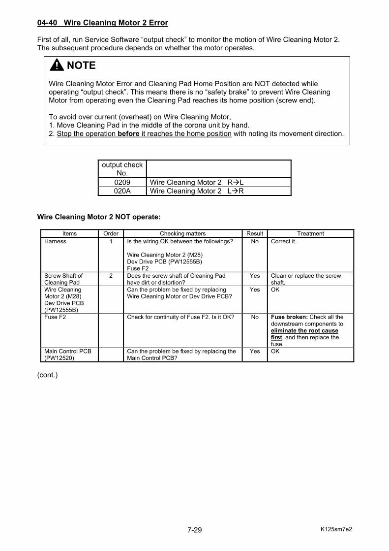
K125sm7e2 7-29
04-40 Wire Cleaning Motor 2 Error First of all, run Service Software “output check” to monitor the motion of Wire Cleaning Motor 2. The subsequent procedure depends on whether the motor operates.
output check No.
0209 Wire Cleaning Motor 2 R L 020A Wire Cleaning Motor 2 L R
Wire Cleaning Motor 2 NOT operate:
Items Order Checking matters Result Treatment Harness 1 Is the wiring OK between the followings?
Wire Cleaning Motor 2 (M28) Dev Drive PCB (PW12555B) Fuse F2
No Correct it.
Screw Shaft of Cleaning Pad
2 Does the screw shaft of Cleaning Pad have dirt or distortion?
Yes Clean or replace the screw shaft.
Wire Cleaning Motor 2 (M28) Dev Drive PCB (PW12555B)
Can the problem be fixed by replacing Wire Cleaning Motor or Dev Drive PCB?
Yes OK
Fuse F2 Check for continuity of Fuse F2. Is it OK? No Fuse broken: Check all the downstream components to eliminate the root cause first, and then replace the fuse.
Main Control PCB (PW12520)
Can the problem be fixed by replacing the Main Control PCB?
Yes OK
(cont.)
NOTE Wire Cleaning Motor Error and Cleaning Pad Home Position are NOT detected while operating “output check”. This means there is no “safety brake” to prevent Wire Cleaning Motor from operating even the Cleaning Pad reaches its home position (screw end). To avoid over current (overheat) on Wire Cleaning Motor, 1. Move Cleaning Pad in the middle of the corona unit by hand. 2. Stop the operation before it reaches the home position with noting its movement direction.
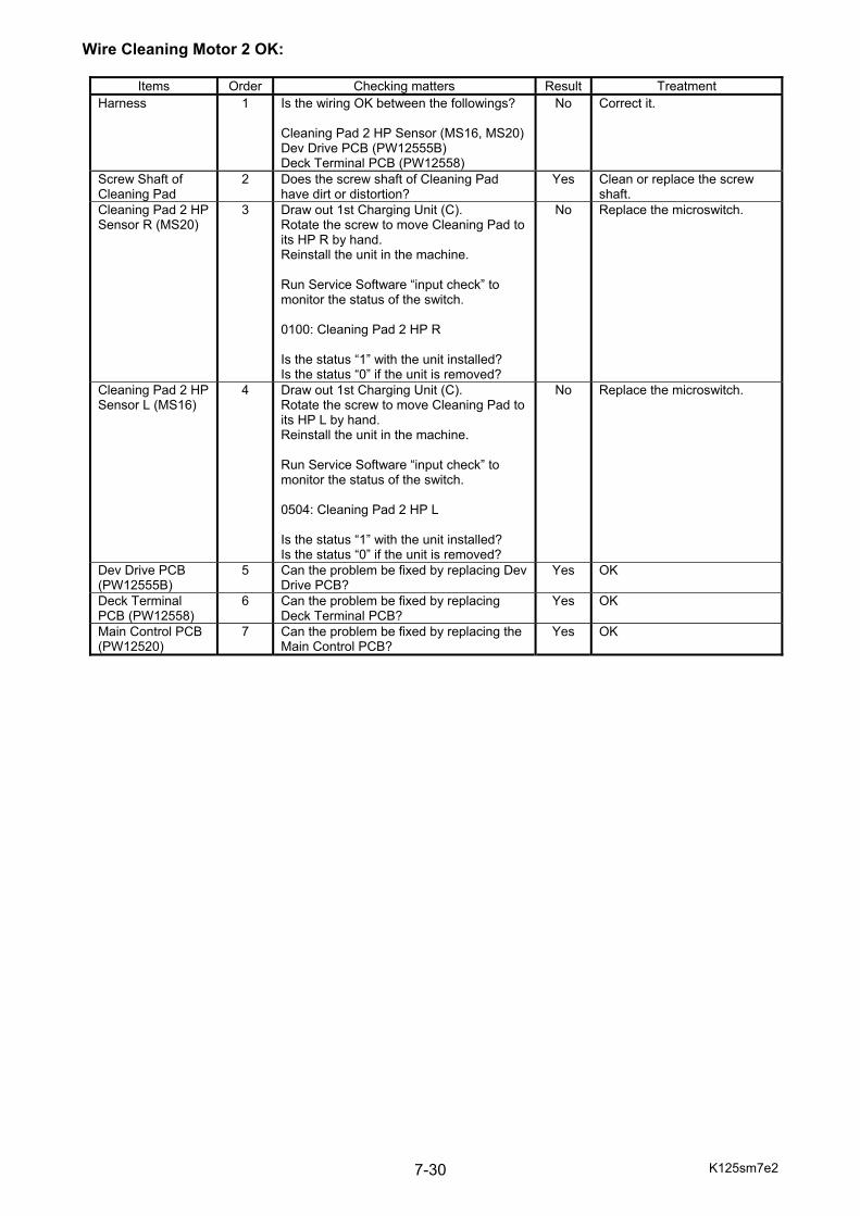
K125sm7e2 7-30
Wire Cleaning Motor 2 OK:
Items Order Checking matters Result Treatment Harness 1 Is the wiring OK between the followings?
Cleaning Pad 2 HP Sensor (MS16, MS20)Dev Drive PCB (PW12555B) Deck Terminal PCB (PW12558)
No Correct it.
Screw Shaft of Cleaning Pad
2 Does the screw shaft of Cleaning Pad have dirt or distortion?
Yes Clean or replace the screw shaft.
Cleaning Pad 2 HP Sensor R (MS20)
3 Draw out 1st Charging Unit (C). Rotate the screw to move Cleaning Pad to its HP R by hand. Reinstall the unit in the machine. Run Service Software “input check” to monitor the status of the switch. 0100: Cleaning Pad 2 HP R Is the status “1” with the unit installed? Is the status “0” if the unit is removed?
No Replace the microswitch.
Cleaning Pad 2 HP Sensor L (MS16)
4 Draw out 1st Charging Unit (C). Rotate the screw to move Cleaning Pad to its HP L by hand. Reinstall the unit in the machine. Run Service Software “input check” to monitor the status of the switch. 0504: Cleaning Pad 2 HP L Is the status “1” with the unit installed? Is the status “0” if the unit is removed?
No Replace the microswitch.
Dev Drive PCB (PW12555B)
5 Can the problem be fixed by replacing Dev Drive PCB?
Yes OK
Deck Terminal PCB (PW12558)
6 Can the problem be fixed by replacing Deck Terminal PCB?
Yes OK
Main Control PCB (PW12520)
7 Can the problem be fixed by replacing the Main Control PCB?
Yes OK

K125sm7e2 7-31
05-01 Dev Press Motor 3 Error First of all, run Service Software “output check” No.030B to monitor the motion of Dev Press Motor 3. The subsequent procedure depends on whether the motor operates. Dev Press Motor 3 NOT operate:
Items Order Checking matters Result Treatment Harness 1 Is the wiring OK between the followings?
Dev Press Motor 3 (M20) Dev Drive PCB (PW12555C) Fuse F3
No Correct it.
Dev Press Motor 3 (M20) Dev Drive PCB (PW12555C)
2 Can the problem be fixed by replacing Dev Press Motor or Dev Drive PCB?
Yes OK
Fuse F3 3 Check for continuity of Fuse F3. Is it OK? No Fuse broken: Check all the downstream components to eliminate the root cause first, and then replace the fuse.
Main Control PCB (PW12520)
4 Can the problem be fixed by replacing the Main Control PCB?
Yes OK
Dev Press Motor 3 OK:
Items Order Checking matters Result Treatment Harness 1 Is the wiring OK between Dev Press
Sensor (PH39) and Dev Drive PCB (PW12555C)?
No Correct it.
Dev Press Sensor (PH39)
2 Can the problem be fixed by replacing Dev Press Sensor?
Yes OK
Dev Drive PCB (PW12555C)
3 Can the problem be fixed by replacing Dev Drive PCB?
Yes OK
Main Control PCB (PW12520)
4 Can the problem be fixed by replacing the Main Control PCB?
Yes OK

K125sm7e2 7-32
05-02 Drum Motor 3 Error First of all, run Service Software “output check” No.0306 to monitor the motion of Drum Motor 3. The subsequent procedure depends on whether the motor operates. Drum Motor 3 NOT operate:
Items Order Checking matters Result Treatment Harness 1 Is the wiring OK between the followings?
Drum Motor 3 (M14) Dev Drive PCB (PW12555C) Fuse F3
No Correct it.
Drum Motor 3 (M14) Dev Drive PCB (PW12555C)
2 Can the problem be fixed by replacing Drum Motor or Dev Drive PCB?
Yes OK
Fuse F3 3 Check for continuity of Fuse F3. Is it OK? No Fuse broken: Check all the downstream components to eliminate the root cause first, and then replace the fuse.
Main Control PCB (PW12520)
4 Can the problem be fixed by replacing the Main Control PCB?
Yes OK
Drum Motor 3 OK:
Items Order Checking matters Result Treatment Harness 1 Is the wiring OK between Drum Motor
Sensors (PH42, PH43) and Dev Drive PCB (PW12555C)?
No Correct it.
Drum Motor Sensor (PH42, PH43)
2 Can the problem be fixed by replacing Drum Motor Sensor?
Yes OK
Dev Drive PCB (PW12555C)
3 Can the problem be fixed by replacing Dev Drive PCB?
Yes OK
Main Control PCB (PW12520)
4 Can the problem be fixed by replacing the Main Control PCB?
Yes OK
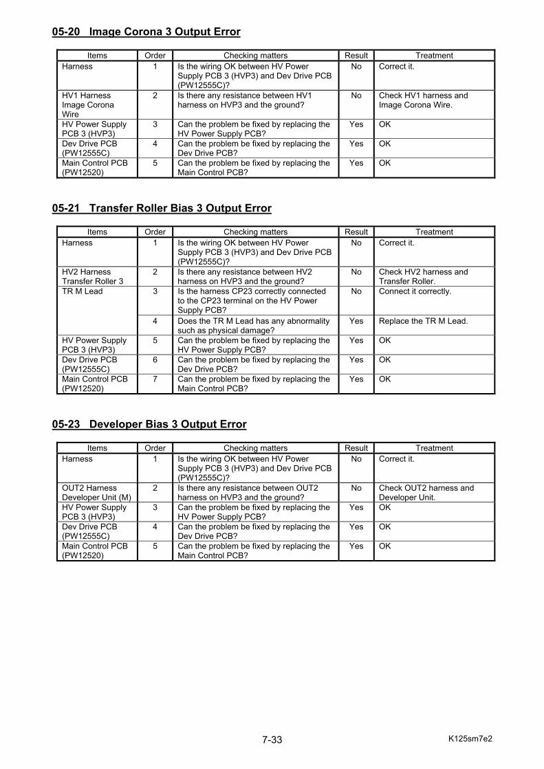
K125sm7e2 7-33
05-20 Image Corona 3 Output Error
Items Order Checking matters Result Treatment Harness 1 Is the wiring OK between HV Power
Supply PCB 3 (HVP3) and Dev Drive PCB (PW12555C)?
No Correct it.
HV1 Harness Image Corona Wire
2 Is there any resistance between HV1 harness on HVP3 and the ground?
No Check HV1 harness and Image Corona Wire.
HV Power Supply PCB 3 (HVP3)
3 Can the problem be fixed by replacing the HV Power Supply PCB?
Yes OK
Dev Drive PCB (PW12555C)
4 Can the problem be fixed by replacing the Dev Drive PCB?
Yes OK
Main Control PCB (PW12520)
5 Can the problem be fixed by replacing the Main Control PCB?
Yes OK
05-21 Transfer Roller Bias 3 Output Error
Items Order Checking matters Result Treatment Harness 1 Is the wiring OK between HV Power
Supply PCB 3 (HVP3) and Dev Drive PCB (PW12555C)?
No Correct it.
HV2 Harness Transfer Roller 3
2 Is there any resistance between HV2 harness on HVP3 and the ground?
No Check HV2 harness and Transfer Roller.
TR M Lead 3 Is the harness CP23 correctly connected to the CP23 terminal on the HV Power Supply PCB?
No Connect it correctly.
4 Does the TR M Lead has any abnormality such as physical damage?
Yes Replace the TR M Lead.
HV Power Supply PCB 3 (HVP3)
5 Can the problem be fixed by replacing the HV Power Supply PCB?
Yes OK
Dev Drive PCB (PW12555C)
6 Can the problem be fixed by replacing the Dev Drive PCB?
Yes OK
Main Control PCB (PW12520)
7 Can the problem be fixed by replacing the Main Control PCB?
Yes OK
05-23 Developer Bias 3 Output Error
Items Order Checking matters Result Treatment Harness 1 Is the wiring OK between HV Power
Supply PCB 3 (HVP3) and Dev Drive PCB (PW12555C)?
No Correct it.
OUT2 Harness Developer Unit (M)
2 Is there any resistance between OUT2 harness on HVP3 and the ground?
No Check OUT2 harness and Developer Unit.
HV Power Supply PCB 3 (HVP3)
3 Can the problem be fixed by replacing the HV Power Supply PCB?
Yes OK
Dev Drive PCB (PW12555C)
4 Can the problem be fixed by replacing the Dev Drive PCB?
Yes OK
Main Control PCB (PW12520)
5 Can the problem be fixed by replacing the Main Control PCB?
Yes OK
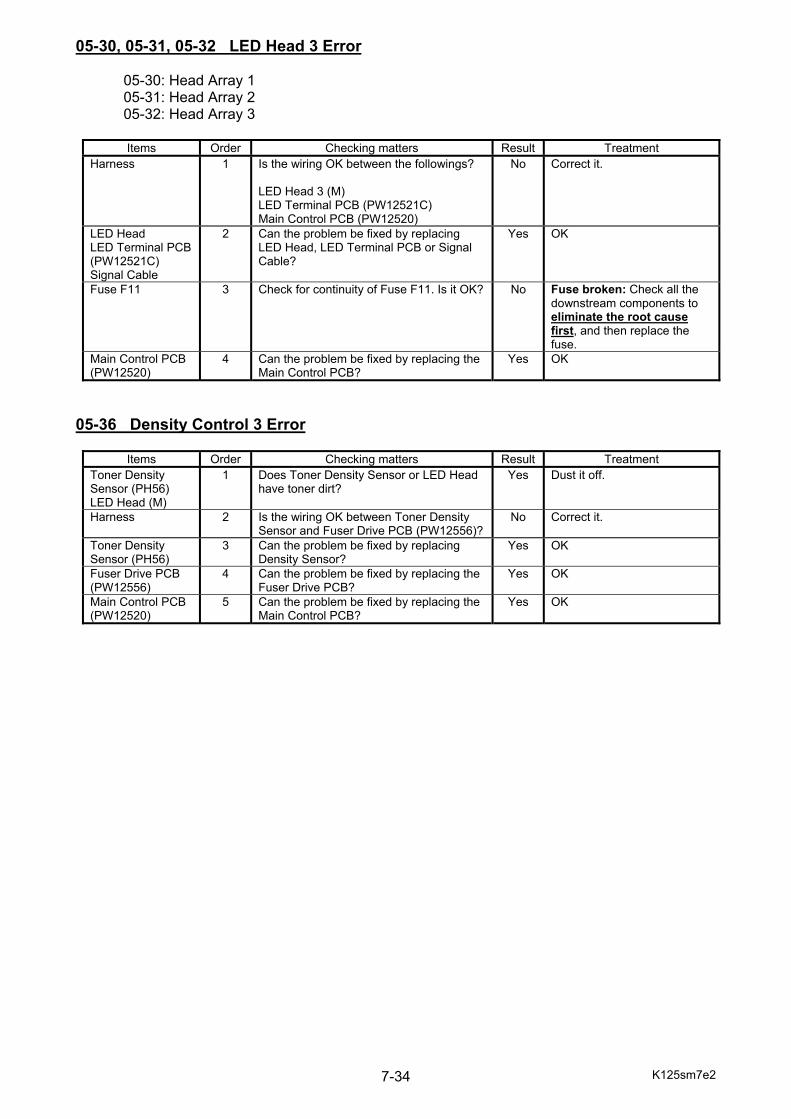
K125sm7e2 7-34
05-30, 05-31, 05-32 LED Head 3 Error 05-30: Head Array 1 05-31: Head Array 2 05-32: Head Array 3
Items Order Checking matters Result Treatment Harness 1 Is the wiring OK between the followings?
LED Head 3 (M) LED Terminal PCB (PW12521C) Main Control PCB (PW12520)
No Correct it.
LED Head LED Terminal PCB (PW12521C) Signal Cable
2 Can the problem be fixed by replacing LED Head, LED Terminal PCB or Signal Cable?
Yes OK
Fuse F11 3 Check for continuity of Fuse F11. Is it OK? No Fuse broken: Check all the downstream components to eliminate the root cause first, and then replace the fuse.
Main Control PCB (PW12520)
4 Can the problem be fixed by replacing the Main Control PCB?
Yes OK
05-36 Density Control 3 Error
Items Order Checking matters Result Treatment Toner Density Sensor (PH56) LED Head (M)
1 Does Toner Density Sensor or LED Head have toner dirt?
Yes Dust it off.
Harness 2 Is the wiring OK between Toner Density Sensor and Fuser Drive PCB (PW12556)?
No Correct it.
Toner Density Sensor (PH56)
3 Can the problem be fixed by replacing Density Sensor?
Yes OK
Fuser Drive PCB (PW12556)
4 Can the problem be fixed by replacing the Fuser Drive PCB?
Yes OK
Main Control PCB (PW12520)
5 Can the problem be fixed by replacing the Main Control PCB?
Yes OK

K125sm7e2 7-35
05-40 Wire Cleaning Motor 3 Error First of all, run Service Software “output check” to monitor the motion of Wire Cleaning Motor 3. The subsequent procedure depends on whether the motor operates.
output check No.
0309 Wire Cleaning Motor 3 R L 030A Wire Cleaning Motor 3 L R
Wire Cleaning Motor 3 NOT operate:
Items Order Checking matters Result Treatment Harness 1 Is the wiring OK between the followings?
Wire Cleaning Motor 3 (M29) Dev Drive PCB (PW12555C) Fuse F3
No Correct it.
Screw Shaft of Cleaning Pad
2 Does the screw shaft of Cleaning Pad have dirt or distortion?
Yes Clean or replace the screw shaft.
Wire Cleaning Motor 3 (M29) Dev Drive PCB (PW12555C)
Can the problem be fixed by replacing Wire Cleaning Motor or Dev Drive PCB?
Yes OK
Fuse F3 Check for continuity of Fuse F3. Is it OK? No Fuse broken: Check all the downstream components to eliminate the root cause first, and then replace the fuse.
Main Control PCB (PW12520)
Can the problem be fixed by replacing the Main Control PCB?
Yes OK
(cont.)
NOTE Wire Cleaning Motor Error and Cleaning Pad Home Position are NOT detected while operating “output check”. This means there is no “safety brake” to prevent Wire Cleaning Motor from operating even the Cleaning Pad reaches its home position (screw end). To avoid over current (overheat) on Wire Cleaning Motor, 1. Move Cleaning Pad in the middle of the corona unit by hand. 2. Stop the operation before it reaches the home position with noting its movement direction.

K125sm7e2 7-36
Wire Cleaning Motor 3 OK:
Items Order Checking matters Result Treatment Harness 1 Is the wiring OK between the followings?
Cleaning Pad 3 HP Sensor (MS17, MS21)Dev Drive PCB (PW12555C) Deck Terminal PCB (PW12558)
No Correct it.
Screw Shaft of Cleaning Pad
2 Does the screw shaft of Cleaning Pad have dirt or distortion?
Yes Clean or replace the screw shaft.
Cleaning Pad 3 HP Sensor R (MS21)
3 Draw out 1st Charging Unit (M). Rotate the screw to move Cleaning Pad to its HP R by hand. Reinstall the unit in the machine. Run Service Software “input check” to monitor the status of the switch. 0200: Cleaning Pad 3 HP R Is the status “1” with the unit installed? Is the status “0” if the unit is removed?
No Replace the microswitch.
Cleaning Pad 3 HP Sensor L (MS17)
4 Draw out 1st Charging Unit (M). Rotate the screw to move Cleaning Pad to its HP L by hand. Reinstall the unit in the machine. Run Service Software “input check” to monitor the status of the switch. 0505: Cleaning Pad 3 HP L Is the status “1” with the unit installed? Is the status “0” if the unit is removed?
No Replace the microswitch.
Dev Drive PCB (PW12555C)
5 Can the problem be fixed by replacing Dev Drive PCB?
Yes OK
Deck Terminal PCB (PW12558)
6 Can the problem be fixed by replacing Deck Terminal PCB?
Yes OK
Main Control PCB (PW12520)
7 Can the problem be fixed by replacing the Main Control PCB?
Yes OK
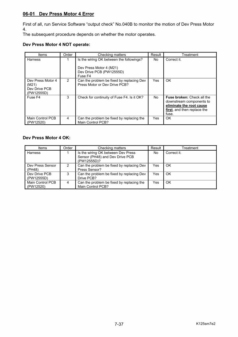
K125sm7e2 7-37
06-01 Dev Press Motor 4 Error First of all, run Service Software “output check” No.040B to monitor the motion of Dev Press Motor 4. The subsequent procedure depends on whether the motor operates. Dev Press Motor 4 NOT operate:
Items Order Checking matters Result Treatment Harness 1 Is the wiring OK between the followings?
Dev Press Motor 4 (M21) Dev Drive PCB (PW12555D) Fuse F4
No Correct it.
Dev Press Motor 4 (M21) Dev Drive PCB (PW12555D)
2 Can the problem be fixed by replacing Dev Press Motor or Dev Drive PCB?
Yes OK
Fuse F4 3 Check for continuity of Fuse F4. Is it OK? No Fuse broken: Check all the downstream components to eliminate the root cause first, and then replace the fuse.
Main Control PCB (PW12520)
4 Can the problem be fixed by replacing the Main Control PCB?
Yes OK
Dev Press Motor 4 OK:
Items Order Checking matters Result Treatment Harness 1 Is the wiring OK between Dev Press
Sensor (PH48) and Dev Drive PCB (PW12555D)?
No Correct it.
Dev Press Sensor (PH48)
2 Can the problem be fixed by replacing Dev Press Sensor?
Yes OK
Dev Drive PCB (PW12555D)
3 Can the problem be fixed by replacing Dev Drive PCB?
Yes OK
Main Control PCB (PW12520)
4 Can the problem be fixed by replacing the Main Control PCB?
Yes OK

K125sm7e2 7-38
06-02 Drum Motor 4 Error First of all, run Service Software “output check” No.0406 to monitor the motion of Drum Motor 4. The subsequent procedure depends on whether the motor operates. Drum Motor 4 NOT operate:
Items Order Checking matters Result Treatment Harness 1 Is the wiring OK between the followings?
Drum Motor 4 (M15) Dev Drive PCB (PW12555D) Fuse F4
No Correct it.
Drum Motor 4 (M15) Dev Drive PCB (PW12555D)
2 Can the problem be fixed by replacing Drum Motor or Dev Drive PCB?
Yes OK
Fuse F4 3 Check for continuity of Fuse F4. Is it OK? No Fuse broken: Check all the downstream components to eliminate the root cause first, and then replace the fuse.
Main Control PCB (PW12520)
4 Can the problem be fixed by replacing the Main Control PCB?
Yes OK
Drum Motor 4 OK:
Items Order Checking matters Result Treatment Harness 1 Is the wiring OK between Drum Motor
Sensors (PH51, PH52) and Dev Drive PCB (PW12555D)?
No Correct it.
Drum Motor Sensor (PH51, PH52)
2 Can the problem be fixed by replacing Drum Motor Sensor?
Yes OK
Dev Drive PCB (PW12555D)
3 Can the problem be fixed by replacing Dev Drive PCB?
Yes OK
Main Control PCB (PW12520)
4 Can the problem be fixed by replacing the Main Control PCB?
Yes OK

K125sm7e2 7-39
06-20 Image Corona 4 Output Error
Items Order Checking matters Result Treatment Harness 1 Is the wiring OK between HV Power
Supply PCB 4 (HVP4) and Dev Drive PCB (PW12555D)?
No Correct it.
HV1 Harness Image Corona Wire
2 Is there any resistance between HV1 harness on HVP4 and the ground?
No Check HV1 harness and Image Corona Wire.
HV Power Supply PCB 4 (HVP4)
3 Can the problem be fixed by replacing the HV Power Supply PCB?
Yes OK
Dev Drive PCB (PW12555D)
4 Can the problem be fixed by replacing the Dev Drive PCB?
Yes OK
Main Control PCB (PW12520)
5 Can the problem be fixed by replacing the Main Control PCB?
Yes OK
06-21 Transfer Roller Bias 4 Output Error
Items Order Checking matters Result Treatment Harness 1 Is the wiring OK between HV Power
Supply PCB 4 (HVP4) and Dev Drive PCB (PW12555D)?
No Correct it.
HV2 Harness Transfer Roller 4
2 Is there any resistance between HV2 harness on HVP4 and the ground?
No Check HV2 harness and Transfer Roller.
TR M Lead 3 Is the harness CP23 correctly connected to the CP23 terminal on the HV Power Supply PCB?
No Connect it correctly.
4 Does the TR M Lead has any abnormality such as physical damage?
Yes Replace the TR M Lead.
HV Power Supply PCB 4 (HVP4)
5 Can the problem be fixed by replacing the HV Power Supply PCB?
Yes OK
Dev Drive PCB (PW12555D)
6 Can the problem be fixed by replacing the Dev Drive PCB?
Yes OK
Main Control PCB (PW12520)
7 Can the problem be fixed by replacing the Main Control PCB?
Yes OK
06-23 Developer Bias 4 Output Error
Items Order Checking matters Result Treatment Harness 1 Is the wiring OK between HV Power
Supply PCB 4 (HVP4) and Dev Drive PCB (PW12555D)?
No Correct it.
OUT2 Harness Developer Unit (Y)
2 Is there any resistance between OUT2 harness on HVP4 and the ground?
No Check OUT2 harness and Developer Unit.
HV Power Supply PCB 4 (HVP4)
3 Can the problem be fixed by replacing the HV Power Supply PCB?
Yes OK
Dev Drive PCB (PW12555D)
4 Can the problem be fixed by replacing the Dev Drive PCB?
Yes OK
Main Control PCB (PW12520)
5 Can the problem be fixed by replacing the Main Control PCB?
Yes OK

K125sm7e2 7-40
06-30, 06-31, 06-32 LED Head 4 Error 06-30: Head Array 1 06-31: Head Array 2 06-32: Head Array 3
Items Order Checking matters Result Treatment Harness 1 Is the wiring OK between the followings?
LED Head 4 (Y) LED Terminal PCB (PW12521D) Main Control PCB (PW12520)
No Correct it.
LED Head LED Terminal PCB (PW12521D) Signal Cable
2 Can the problem be fixed by replacing LED Head, LED Terminal PCB or Signal Cable?
Yes OK
Fuse F12 3 Check for continuity of Fuse F12. Is it OK? No Fuse broken: Check all the downstream components to eliminate the root cause first, and then replace the fuse.
Main Control PCB (PW12520)
4 Can the problem be fixed by replacing the Main Control PCB?
Yes OK
06-36 Density Control 4 Error
Items Order Checking matters Result Treatment Toner Density Sensor (PH56) LED Head (Y)
1 Does Toner Density Sensor or LED Head have toner dirt?
Yes Dust it off.
Harness 2 Is the wiring OK between Toner Density Sensor and Fuser Drive PCB (PW12556)?
No Correct it.
Toner Density Sensor (PH56)
3 Can the problem be fixed by replacing Density Sensor?
Yes OK
Fuser Drive PCB (PW12556)
4 Can the problem be fixed by replacing the Fuser Drive PCB?
Yes OK
Main Control PCB (PW12520)
5 Can the problem be fixed by replacing the Main Control PCB?
Yes OK

K125sm7e2 7-41
06-40 Wire Cleaning Motor 4 Error First of all, run Service Software “output check” to monitor the motion of Wire Cleaning Motor 4. The subsequent procedure depends on whether the motor operates.
output check No.
0409 Wire Cleaning Motor 4 R L 040A Wire Cleaning Motor 4 L R
Wire Cleaning Motor 4 NOT operate:
Items Order Checking matters Result Treatment Harness 1 Is the wiring OK between the followings?
Wire Cleaning Motor 4 (M30) Dev Drive PCB (PW12555D) Fuse F3
No Correct it.
Screw Shaft of Cleaning Pad
2 Does the screw shaft of Cleaning Pad have dirt or distortion?
Yes Clean or replace the screw shaft.
Wire Cleaning Motor 4 (M30) Dev Drive PCB (PW12555D)
Can the problem be fixed by replacing Wire Cleaning Motor or Dev Drive PCB?
Yes OK
Fuse F4 Check for continuity of Fuse F4. Is it OK? No Fuse broken: Check all the downstream components to eliminate the root cause first, and then replace the fuse.
Main Control PCB (PW12520)
Can the problem be fixed by replacing the Main Control PCB?
Yes OK
(cont.)
NOTE Wire Cleaning Motor Error and Cleaning Pad Home Position are NOT detected while operating “output check”. This means there is no “safety brake” to prevent Wire Cleaning Motor from operating even the Cleaning Pad reaches its home position (screw end). To avoid over current (overheat) on Wire Cleaning Motor, 1. Move Cleaning Pad in the middle of the corona unit by hand. 2. Stop the operation before it reaches the home position with noting its movement direction.

K125sm7e2 7-42
Wire Cleaning Motor 4 OK:
Items Order Checking matters Result Treatment Harness 1 Is the wiring OK between the followings?
Cleaning Pad 4 HP Sensor (MS18, MS22)Dev Drive PCB (PW12555D) Deck Terminal PCB (PW12558)
No Correct it.
Screw Shaft of Cleaning Pad
2 Does the screw shaft of Cleaning Pad have dirt or distortion?
Yes Clean or replace the screw shaft.
Cleaning Pad 4 HP Sensor R (MS22)
3 Draw out 1st Charging Unit (Y). Rotate the screw to move Cleaning Pad to its HP R by hand. Reinstall the unit in the machine. Run Service Software “input check” to monitor the status of the switch. 0300: Cleaning Pad 4 HP R Is the status “1” with the unit installed? Is the status “0” if the unit is removed?
No Replace the microswitch.
Cleaning Pad 4 HP Sensor L (MS18)
4 Draw out 1st Charging Unit (Y). Rotate the screw to move Cleaning Pad to its HP L by hand. Reinstall the unit in the machine. Run Service Software “input check” to monitor the status of the switch. 0506: Cleaning Pad 4 HP L Is the status “1” with the unit installed? Is the status “0” if the unit is removed?
No Replace the microswitch.
Dev Drive PCB (PW12555D)
5 Can the problem be fixed by replacing Dev Drive PCB?
Yes OK
Deck Terminal PCB (PW12558)
6 Can the problem be fixed by replacing Deck Terminal PCB?
Yes OK
Main Control PCB (PW12520)
7 Can the problem be fixed by replacing the Main Control PCB?
Yes OK
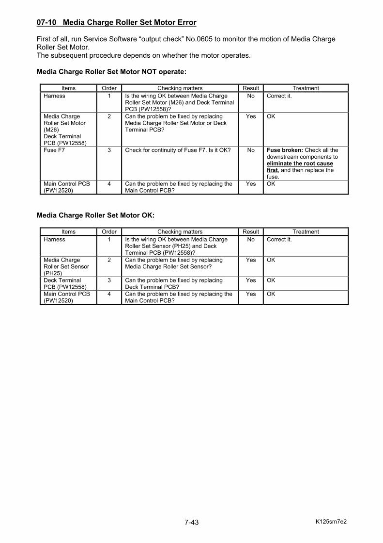
K125sm7e2 7-43
07-10 Media Charge Roller Set Motor Error First of all, run Service Software “output check” No.0605 to monitor the motion of Media Charge Roller Set Motor. The subsequent procedure depends on whether the motor operates. Media Charge Roller Set Motor NOT operate:
Items Order Checking matters Result Treatment Harness 1 Is the wiring OK between Media Charge
Roller Set Motor (M26) and Deck Terminal PCB (PW12558)?
No Correct it.
Media Charge Roller Set Motor (M26) Deck Terminal PCB (PW12558)
2 Can the problem be fixed by replacing Media Charge Roller Set Motor or Deck Terminal PCB?
Yes OK
Fuse F7 3 Check for continuity of Fuse F7. Is it OK? No Fuse broken: Check all the downstream components to eliminate the root cause first, and then replace the fuse.
Main Control PCB (PW12520)
4 Can the problem be fixed by replacing the Main Control PCB?
Yes OK
Media Charge Roller Set Motor OK:
Items Order Checking matters Result Treatment Harness 1 Is the wiring OK between Media Charge
Roller Set Sensor (PH25) and Deck Terminal PCB (PW12558)?
No Correct it.
Media Charge Roller Set Sensor (PH25)
2 Can the problem be fixed by replacing Media Charge Roller Set Sensor?
Yes OK
Deck Terminal PCB (PW12558)
3 Can the problem be fixed by replacing Deck Terminal PCB?
Yes OK
Main Control PCB (PW12520)
4 Can the problem be fixed by replacing the Main Control PCB?
Yes OK
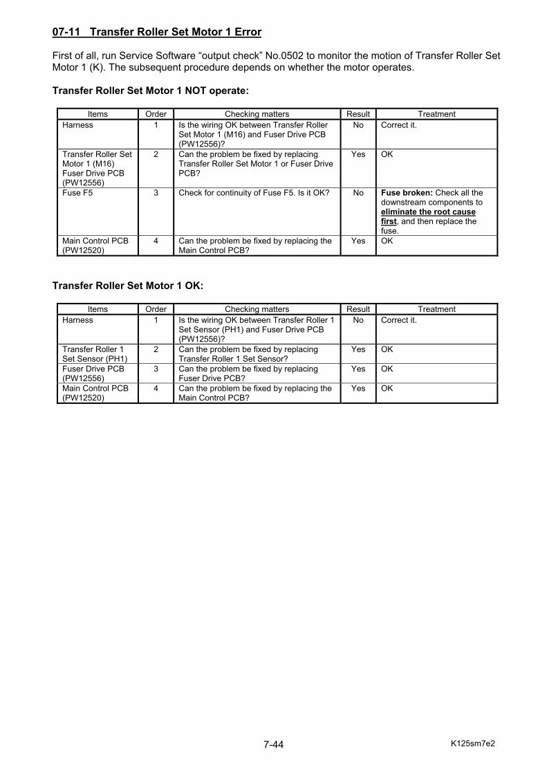
K125sm7e2 7-44
07-11 Transfer Roller Set Motor 1 Error First of all, run Service Software “output check” No.0502 to monitor the motion of Transfer Roller Set Motor 1 (K). The subsequent procedure depends on whether the motor operates. Transfer Roller Set Motor 1 NOT operate:
Items Order Checking matters Result Treatment Harness 1 Is the wiring OK between Transfer Roller
Set Motor 1 (M16) and Fuser Drive PCB (PW12556)?
No Correct it.
Transfer Roller Set Motor 1 (M16) Fuser Drive PCB (PW12556)
2 Can the problem be fixed by replacing Transfer Roller Set Motor 1 or Fuser Drive PCB?
Yes OK
Fuse F5 3 Check for continuity of Fuse F5. Is it OK? No Fuse broken: Check all the downstream components to eliminate the root cause first, and then replace the fuse.
Main Control PCB (PW12520)
4 Can the problem be fixed by replacing the Main Control PCB?
Yes OK
Transfer Roller Set Motor 1 OK:
Items Order Checking matters Result Treatment Harness 1 Is the wiring OK between Transfer Roller 1
Set Sensor (PH1) and Fuser Drive PCB (PW12556)?
No Correct it.
Transfer Roller 1 Set Sensor (PH1)
2 Can the problem be fixed by replacing Transfer Roller 1 Set Sensor?
Yes OK
Fuser Drive PCB (PW12556)
3 Can the problem be fixed by replacing Fuser Drive PCB?
Yes OK
Main Control PCB (PW12520)
4 Can the problem be fixed by replacing the Main Control PCB?
Yes OK
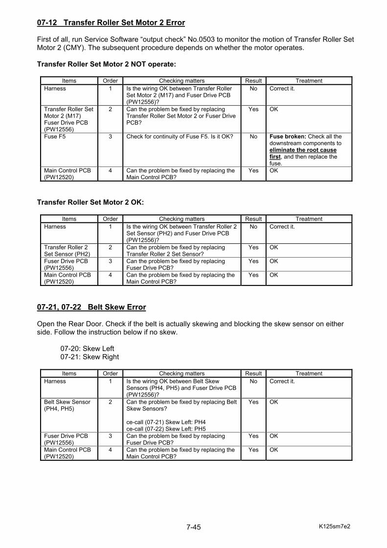
K125sm7e2 7-45
07-12 Transfer Roller Set Motor 2 Error First of all, run Service Software “output check” No.0503 to monitor the motion of Transfer Roller Set Motor 2 (CMY). The subsequent procedure depends on whether the motor operates. Transfer Roller Set Motor 2 NOT operate:
Items Order Checking matters Result Treatment Harness 1 Is the wiring OK between Transfer Roller
Set Motor 2 (M17) and Fuser Drive PCB (PW12556)?
No Correct it.
Transfer Roller Set Motor 2 (M17) Fuser Drive PCB (PW12556)
2 Can the problem be fixed by replacing Transfer Roller Set Motor 2 or Fuser Drive PCB?
Yes OK
Fuse F5 3 Check for continuity of Fuse F5. Is it OK? No Fuse broken: Check all the downstream components to eliminate the root cause first, and then replace the fuse.
Main Control PCB (PW12520)
4 Can the problem be fixed by replacing the Main Control PCB?
Yes OK
Transfer Roller Set Motor 2 OK:
Items Order Checking matters Result Treatment Harness 1 Is the wiring OK between Transfer Roller 2
Set Sensor (PH2) and Fuser Drive PCB (PW12556)?
No Correct it.
Transfer Roller 2 Set Sensor (PH2)
2 Can the problem be fixed by replacing Transfer Roller 2 Set Sensor?
Yes OK
Fuser Drive PCB (PW12556)
3 Can the problem be fixed by replacing Fuser Drive PCB?
Yes OK
Main Control PCB (PW12520)
4 Can the problem be fixed by replacing the Main Control PCB?
Yes OK
07-21, 07-22 Belt Skew Error Open the Rear Door. Check if the belt is actually skewing and blocking the skew sensor on either side. Follow the instruction below if no skew. 07-20: Skew Left 07-21: Skew Right
Items Order Checking matters Result Treatment Harness 1 Is the wiring OK between Belt Skew
Sensors (PH4, PH5) and Fuser Drive PCB (PW12556)?
No Correct it.
Belt Skew Sensor (PH4, PH5)
2 Can the problem be fixed by replacing Belt Skew Sensors? ce-call (07-21) Skew Left: PH4 ce-call (07-22) Skew Left: PH5
Yes OK
Fuser Drive PCB (PW12556)
3 Can the problem be fixed by replacing Fuser Drive PCB?
Yes OK
Main Control PCB (PW12520)
4 Can the problem be fixed by replacing the Main Control PCB?
Yes OK
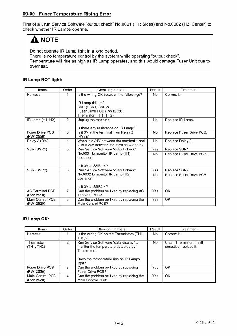
K125sm7e2 7-46
09-00 Fuser Temperature Rising Error First of all, run Service Software “output check” No.0001 (H1: Sides) and No.0002 (H2: Center) to check whether IR Lamps operate. IR Lamp NOT light:
Items Order Checking matters Result Treatment Harness 1 Is the wiring OK between the followings?
IR Lamp (H1, H2) SSR (SSR1, SSR2) Fuser Drive PCB (PW12556) Thermistor (TH1, TH2)
No Correct it.
IR Lamp (H1, H2) 2 Unplug the machine. Is there any resistance on IR Lamp?
No Replace IR Lamp.
Fuser Drive PCB (PW12556)
3 Is it 0V at the terminal 1 on Relay 2 (RY2)?
No Replace Fuser Drive PCB.
Relay 2 (RY2) 4 When it is 24V between the terminal 1 and 2, is it 24V between the terminal 4 and 8?
No Replace Relay 2.
SSR (SSR1) 5 Run Service Software “output check” No.0001 to monitor IR Lamp (H1) operation. Is it 0V at SSR1-4?
Yes Replace SSR1. No Replace Fuser Drive PCB.
SSR (SSR2) 6 Run Service Software “output check” No.0002 to monitor IR Lamp (H2) operation. Is it 0V at SSR2-4?
Yes Replace SSR2. No Replace Fuser Drive PCB.
AC Terminal PCB (PW12510)
7 Can the problem be fixed by replacing AC Terminal PCB?
Yes OK
Main Control PCB (PW12520)
8 Can the problem be fixed by replacing the Main Control PCB?
Yes OK
IR Lamp OK:
Items Order Checking matters Result Treatment Harness 1 Is the wiring OK on the Thermistors (TH1,
TH2)? No Correct it.
Thermistor (TH1, TH2)
2 Run Service Software “data display” to monitor the temperature detected by Thermistors. Does the temperature rise as IP Lamps light?
No Clean Thermistor. If still unsettled, replace it.
Fuser Drive PCB (PW12556)
3 Can the problem be fixed by replacing Fuser Drive PCB?
Yes OK
Main Control PCB (PW12520)
4 Can the problem be fixed by replacing the Main Control PCB?
Yes OK
NOTE Do not operate IR Lamp light in a long period. There is no temperature control by the system while operating “output check”. Temperature will rise as high as IR Lamp operates, and this would damage Fuser Unit due to overheat.

K125sm7e2 7-47
09-01 Fuser Abnormal High Temperature Error First of all, run Service Software “output check” No.0001 (H1: Sides) and No.0002 (H2: Center) to check whether IR Lamps operate properly. IR Lamp lights but not turn OFF:
Items Order Checking matters Result Treatment Harness 1 Is the wiring OK between the followings?
IR Lamp (H1, H2) SSR (SSR1, SSR2) Fuser Drive PCB (PW12556) Thermistor (TH1, TH2)
No Correct it.
Fuser Drive PCB (PW12556)
2 Run Service Software “output check”, and select [stop all]. Is it 24V at SSR1-4 and SSR2-4?
No Replace Fuser Drive PCB.
Yes If temperature rises at 24V, replace SSR1 or SSR2.
Main Control PCB (PW12520)
3 Can the problem be fixed by replacing the Main Control PCB?
Yes OK
IR Lamp controlled ON/OFF properly:
Items Order Checking matters Result Treatment Harness 1 Is the wiring OK on the Thermistors (TH1,
TH2)? No Correct it.
Thermistor (TH1, TH2)
2 Run Service Software “data display” to monitor the temperature detected by Thermistors. Does the temperature rise as IP Lamps light?
No Clean Thermistor. If still unsettled, replace it.
Fuser Drive PCB (PW12556)
3 Can the problem be fixed by replacing Fuser Drive PCB?
Yes OK
Main Control PCB (PW12520)
4 Can the problem be fixed by replacing the Main Control PCB?
Yes OK
NOTE Do not operate IR Lamp light in a long period. There is no temperature control by the system while operating “output check”. Temperature will rise as high as IR Lamp operates, and this would damage Fuser Unit due to overheat.
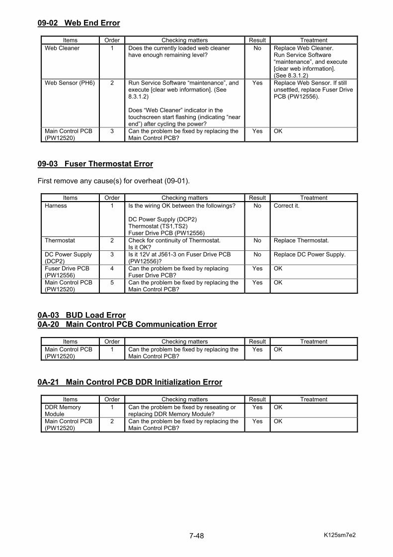
K125sm7e2 7-48
09-02 Web End Error
Items Order Checking matters Result Treatment Web Cleaner 1 Does the currently loaded web cleaner
have enough remaining level? No Replace Web Cleaner.
Run Service Software “maintenance”, and execute [clear web information]. (See 8.3.1.2)
Web Sensor (PH6) 2 Run Service Software “maintenance”, and execute [clear web information]. (See 8.3.1.2) Does “Web Cleaner” indicator in the touchscreen start flashing (indicating “near end”) after cycling the power?
Yes Replace Web Sensor. If still unsettled, replace Fuser Drive PCB (PW12556).
Main Control PCB (PW12520)
3 Can the problem be fixed by replacing the Main Control PCB?
Yes OK
09-03 Fuser Thermostat Error First remove any cause(s) for overheat (09-01).
Items Order Checking matters Result Treatment Harness 1 Is the wiring OK between the followings?
DC Power Supply (DCP2) Thermostat (TS1,TS2) Fuser Drive PCB (PW12556)
No Correct it.
Thermostat 2 Check for continuity of Thermostat. Is it OK?
No Replace Thermostat.
DC Power Supply (DCP2)
3 Is it 12V at J561-3 on Fuser Drive PCB (PW12556)?
No Replace DC Power Supply.
Fuser Drive PCB (PW12556)
4 Can the problem be fixed by replacing Fuser Drive PCB?
Yes OK
Main Control PCB (PW12520)
5 Can the problem be fixed by replacing the Main Control PCB?
Yes OK
0A-03 BUD Load Error 0A-20 Main Control PCB Communication Error
Items Order Checking matters Result Treatment Main Control PCB (PW12520)
1 Can the problem be fixed by replacing the Main Control PCB?
Yes OK
0A-21 Main Control PCB DDR Initialization Error
Items Order Checking matters Result Treatment DDR Memory Module
1 Can the problem be fixed by reseating or replacing DDR Memory Module?
Yes OK
Main Control PCB (PW12520)
2 Can the problem be fixed by replacing the Main Control PCB?
Yes OK
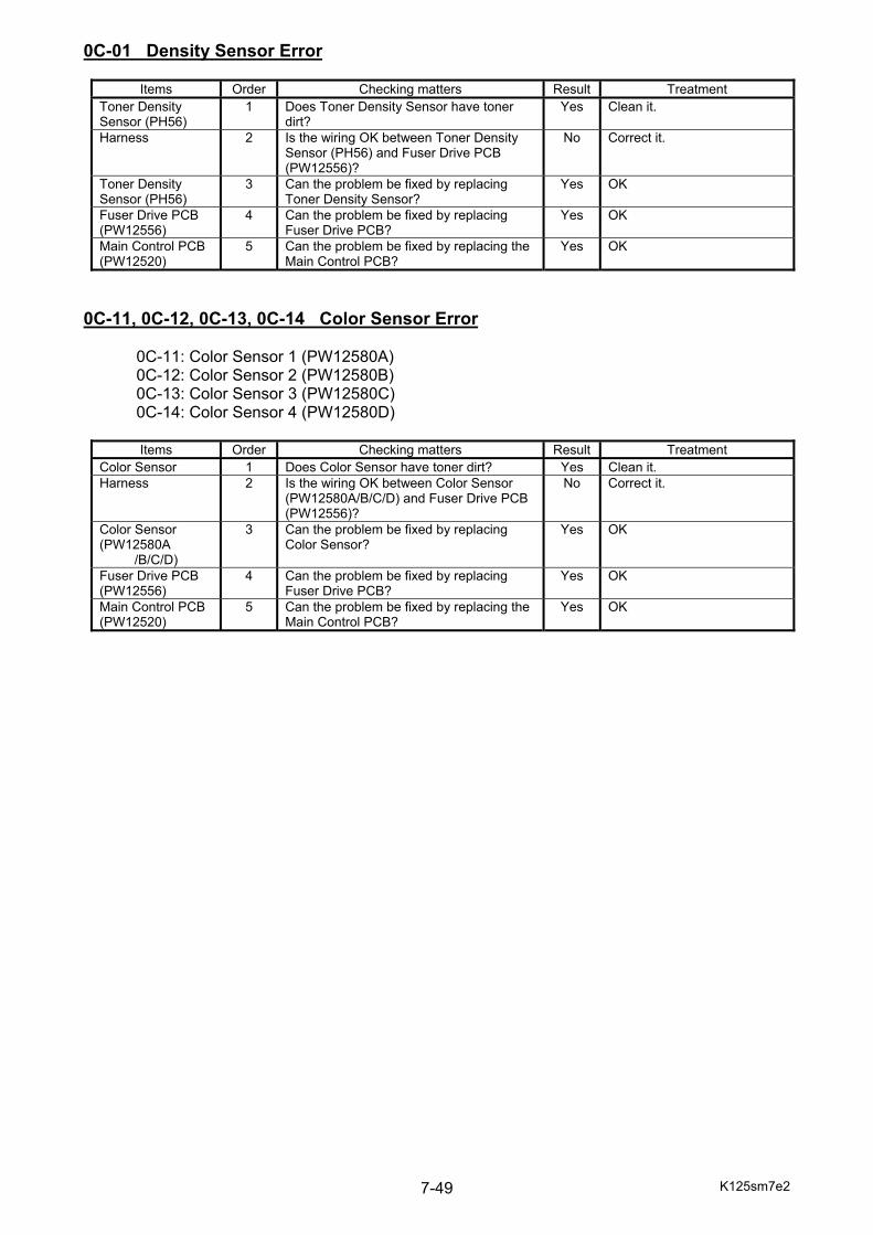
K125sm7e2 7-49
0C-01 Density Sensor Error
Items Order Checking matters Result Treatment Toner Density Sensor (PH56)
1 Does Toner Density Sensor have toner dirt?
Yes Clean it.
Harness 2 Is the wiring OK between Toner Density Sensor (PH56) and Fuser Drive PCB (PW12556)?
No Correct it.
Toner Density Sensor (PH56)
3 Can the problem be fixed by replacing Toner Density Sensor?
Yes OK
Fuser Drive PCB (PW12556)
4 Can the problem be fixed by replacing Fuser Drive PCB?
Yes OK
Main Control PCB (PW12520)
5 Can the problem be fixed by replacing the Main Control PCB?
Yes OK
0C-11, 0C-12, 0C-13, 0C-14 Color Sensor Error 0C-11: Color Sensor 1 (PW12580A) 0C-12: Color Sensor 2 (PW12580B) 0C-13: Color Sensor 3 (PW12580C) 0C-14: Color Sensor 4 (PW12580D)
Items Order Checking matters Result Treatment Color Sensor 1 Does Color Sensor have toner dirt? Yes Clean it. Harness 2 Is the wiring OK between Color Sensor
(PW12580A/B/C/D) and Fuser Drive PCB (PW12556)?
No Correct it.
Color Sensor (PW12580A
/B/C/D)
3 Can the problem be fixed by replacing Color Sensor?
Yes OK
Fuser Drive PCB (PW12556)
4 Can the problem be fixed by replacing Fuser Drive PCB?
Yes OK
Main Control PCB (PW12520)
5 Can the problem be fixed by replacing the Main Control PCB?
Yes OK
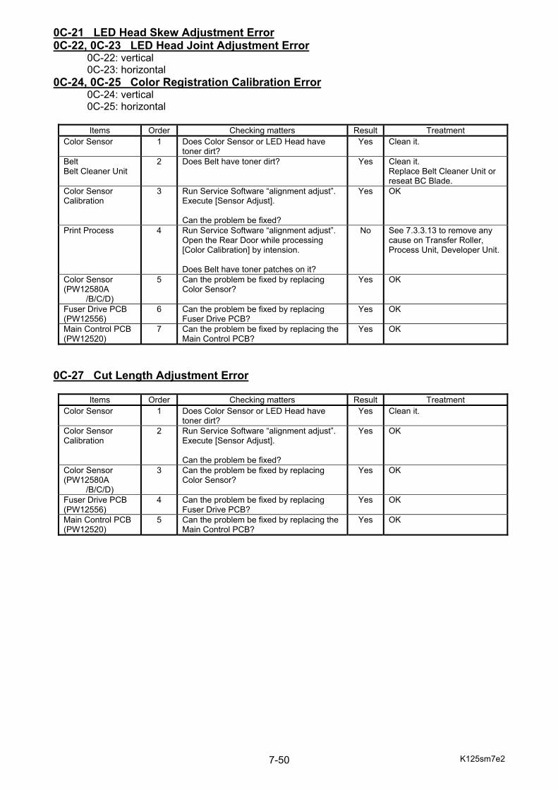
K125sm7e2 7-50
0C-21 LED Head Skew Adjustment Error 0C-22, 0C-23 LED Head Joint Adjustment Error 0C-22: vertical 0C-23: horizontal 0C-24, 0C-25 Color Registration Calibration Error 0C-24: vertical 0C-25: horizontal
Items Order Checking matters Result Treatment Color Sensor 1 Does Color Sensor or LED Head have
toner dirt? Yes Clean it.
Belt Belt Cleaner Unit
2 Does Belt have toner dirt? Yes Clean it. Replace Belt Cleaner Unit or reseat BC Blade.
Color Sensor Calibration
3 Run Service Software “alignment adjust”. Execute [Sensor Adjust]. Can the problem be fixed?
Yes OK
Print Process 4 Run Service Software “alignment adjust”. Open the Rear Door while processing [Color Calibration] by intension. Does Belt have toner patches on it?
No See 7.3.3.13 to remove any cause on Transfer Roller, Process Unit, Developer Unit.
Color Sensor (PW12580A
/B/C/D)
5 Can the problem be fixed by replacing Color Sensor?
Yes OK
Fuser Drive PCB (PW12556)
6 Can the problem be fixed by replacing Fuser Drive PCB?
Yes OK
Main Control PCB (PW12520)
7 Can the problem be fixed by replacing the Main Control PCB?
Yes OK
0C-27 Cut Length Adjustment Error
Items Order Checking matters Result Treatment Color Sensor 1 Does Color Sensor or LED Head have
toner dirt? Yes Clean it.
Color Sensor Calibration
2 Run Service Software “alignment adjust”. Execute [Sensor Adjust]. Can the problem be fixed?
Yes OK
Color Sensor (PW12580A
/B/C/D)
3 Can the problem be fixed by replacing Color Sensor?
Yes OK
Fuser Drive PCB (PW12556)
4 Can the problem be fixed by replacing Fuser Drive PCB?
Yes OK
Main Control PCB (PW12520)
5 Can the problem be fixed by replacing the Main Control PCB?
Yes OK

K125sm7e2 7-51
0D-01, 0D-02, 0D-03, 0D-04 Cooling Fan Error 0D-01: Cooling Fan 1 0D-02: Cooling Fan 2 0D-03: Cooling Fan 3 0D-04: Cooling Fan 4
Items Order Checking matters Result Treatment Harness 1 Is the wiring OK between the followings?
Cooling Fan (FM1/FM2/FM3/FM4) Dev Drive PCB (PW12555A/B/C/D)
No Correct it.
Cooling Fan 2 Can the problem be fixed by replacing the Cooling Fan?
Yes OK
Dev Drive PCB (PW12555
A/B/C/D)
3 Can the problem be fixed by replacing the Dev Drive PCB?
Yes OK
Main Control PCB (PW12520)
4 Can the problem be fixed by replacing the Main Control PCB?
Yes OK
0D-05, 0D-06 DCP Cooling Fan Error 0D-05: DCP Cooling Fan 1 0D-06: DCP Cooling Fan 2
Items Order Checking matters Result Treatment Harness 1 Is the wiring OK between the followings?
Cooling Fan (FM8/FM9) Dev Drive PCB (PW12555A/B)
No Correct it.
DCP Cooling Fan 2 Can the problem be fixed by replacing the DCP Cooling Fan?
Yes OK
Dev Drive PCB (PW12555A/B)
3 Can the problem be fixed by replacing the Dev Drive PCB?
Yes OK
Main Control PCB (PW12520)
4 Can the problem be fixed by replacing the Main Control PCB?
Yes OK
0D-07, 0D-08 IPS Cooling Fan Error 0D-07: IPS Cooling Fan 1 0D-08: IPS Cooling Fan 2
Items Order Checking matters Result Treatment Harness 1 Is the wiring OK between the followings?
Cooling Fan (FM10, FM11) Fuser Drive PCB (PW12556)
No Correct it.
IPS Cooling Fan 2 Can the problem be fixed by replacing the IPS Cooling Fan?
Yes OK
Fuser Drive PCB (PW12556)
3 Can the problem be fixed by replacing the Fuser Drive PCB?
Yes OK
Main Control PCB (PW12520)
4 Can the problem be fixed by replacing the Main Control PCB?
Yes OK

K125sm7e2 7-52
0D-09, 0D-0A Fuser Blower Error 0D-09: Fuser Blower 1 0D-0A: Fuser Blower 2
Items Order Checking matters Result Treatment Harness 1 Is the wiring OK between the followings?
Fuser Blower (BL1, BL2) Fuser Drive PCB (PW12556)
No Correct it.
Fuser Blower 2 Can the problem be fixed by replacing the Fuser Blower?
Yes OK
Fuser Drive PCB (PW12556)
3 Can the problem be fixed by replacing the Fuser Drive PCB?
Yes OK
Main Control PCB (PW12520)
4 Can the problem be fixed by replacing the Main Control PCB?
Yes OK
K125sm7e2 7-53
7. 2. 2 Occurrence Condition of Service Call Error
Error Code Error Name Error conditions 01-11 Roll Deck 1 Cutter Error Blade not detected at HP within 2 seconds. 01-12 Roll Deck 2 Cutter Error 01-13 Roll Deck 3 Cutter Error 03-01 Developer Press Motor 1 Error (1) Developer Unit (K) is not placed to the setting position
although 9 seconds has passed. (2) Developer Unit (K) is not separated although 9 seconds
has passed. 03-02 Drum Motor 1 Error “Abnormal output signal” shows “1” for longer than 100msec. 03-20 Image Corona 1 Output Error “Abnormal output signal” shows “1” for longer than 100msec. 03-21 Transfer Roller Bias 1 Output Error “Abnormal output signal” shows “1” for longer than 100msec. 03-23 Developer Bias 1 Output Error “Abnormal output signal” shows “1” for longer than 100msec. 03-30 LED Head 1 Array 1 Error Initialization of LED Head is failed 6 times at turning on or
when recovered from the Cold Sleep. 03-31 LED Head 1 Array 2 Error Initialization of LED Head is failed 6 times at turning on or
when recovered from the Cold Sleep. 03-32 LED Head 1 Array 3 Error Initialization of LED Head is failed 6 times at turning on or
when recovered from the Cold Sleep. 03-36 Density Control 1 error Density is not adjusted satisfactory by Density Control. 03-40 Wire Cleaning Motor 1 Error Wire Cleaner does not arrive at another end within 70
seconds since the start of cleaning. 04-01 Developer Press Motor 2 Error (1) Developer Unit (C) is not placed to the setting position
although 9 seconds has passed. (2) Developer Unit (C) is not separated although 9 seconds
has passed. 04-02 Drum Motor 2 Error “Abnormal output signal” shows “1” for longer than 100msec. 04-20 Image Corona 2 Output Error “Abnormal output signal” shows “1” for longer than 100msec. 04-21 Transfer Roller Bias 2 Output Error “Abnormal output signal” shows “1” for longer than 100msec. 04-23 Developer Bias 2 Output Error “Abnormal output signal” shows “1” for longer than 100msec. 04-30 LED Head 2 Array 1 Error Initialization of LED Head is failed 6 times at turning on or
when recovered from the Cold Sleep. 04-31 LED Head 2 Array 2 Error Initialization of LED Head is failed 6 times at turning on or
when recovered from the Cold Sleep. 04-32 LED Head 2 Array 3 Error Initialization of LED Head is failed 6 times at turning on or
when recovered from the Cold Sleep. 04-36 Density Control 2 error Density is not adjusted satisfactory by Density Control. 04-40 Wire Cleaning Motor 2 Error Wire Cleaner does not arrive at another end within 70
seconds since the start of cleaning. 05-01 Developer Press Motor 3 Error (1) Developer Unit (M) is not placed to the setting position
although 9 seconds has passed. (2) Developer Unit (M) is not separated although 9 seconds
has passed. 05-02 Drum Motor 3 Error “Abnormal output signal” shows “1” for longer than 100msec. 05-20 Image Corona 3 Output Error “Abnormal output signal” shows “1” for longer than 100msec. 05-21 Transfer Roller Bias 3 Output Error “Abnormal output signal” shows “1” for longer than 100msec. 05-23 Developer Bias 3 Output Error “Abnormal output signal” shows “1” for longer than 100msec. 05-30 LED Head 3 Array 1 Error Initialization of LED Head is failed 6 times at turning on or
when recovered from the Cold Sleep. 05-31 LED Head 3 Array 2 Error Initialization of LED Head is failed 6 times at turning on or
when recovered from the Cold Sleep. 05-32 LED Head 3 Array 3 Error Initialization of LED Head is failed 6 times at turning on or
when recovered from the Cold Sleep. 05-36 Density Control 3 error Density is not adjusted satisfactory by Density Control. 05-40 Wire Cleaning Motor 3 Error Wire Cleaner does not arrive at another end within 70
seconds since the start of cleaning. 06-01 Developer Press Motor 4 Error (1) Developer Unit (Y) is not placed to the setting position
although 9 seconds has passed. (2) Developer Unit (Y) is not separated although 9 seconds
has passed. 06-02 Drum Motor 4 Error “Abnormal output signal” shows “1” for longer than 100msec. 06-20 Image Corona 4 Output Error “Abnormal output signal” shows “1” for longer than 100msec. 06-21 Transfer Roller Bias 4 Output Error “Abnormal output signal” shows “1” for longer than 100msec. 06-23 Developer Bias 4 Output Error “Abnormal output signal” shows “1” for longer than 100msec. 06-30 LED Head 4 Array 1 Error Initialization of LED Head is failed 6 times at turning on or
when recovered from the Cold Sleep. 06-31 LED Head 4 Array 2 Error Initialization of LED Head is failed 6 times at turning on or
when recovered from the Cold Sleep. 06-32 LED Head 4 Array 3 Error Initialization of LED Head is failed 6 times at turning on or
when recovered from the Cold Sleep.
K125sm7e2 7-54
06-36 Density Control 4 error Density is not adjusted satisfactory by Density Control. 06-40 Wire Cleaning Motor 4 Error Wire Cleaner does not arrive at another end within 70
seconds since the start of cleaning. 07-10 Media Charge Roller Set Motor
Error (1) Media Charge Roller is not placed to the setting position
although 9 seconds has passed. (2) Media Charge Rollet is not separated although 9 seconds
has passed. 07-11 Transfer Roller Set Motor 1 Error (1) Transfer Roller (K) is not placed to the setting position
although 9 seconds has passed. (2) Transfer Roller (K) is not separated although 9 seconds
has passed. 07-12 Transfer Roller Set Motor 2 Error (1) Transfer Roller (CMY) is not placed to the setting position
although 9 seconds has passed. (2) Transfer Roller (CMY) is not separated although 9
seconds has passed. 07-21 Belt Skew L Error Skew Sensor L shows “1” for longer than 100msec. 07-22 Belt Skew R Error Skew Sensor R shows “1” for longer than 100msec. 09-00 Fuser Temperature Rising Error (1) Fuser is not heated up to 50Co within 6 minutes after
turning on. (before 02.00A: 2 minutes) (2) Fuser is not heated up to 100Co within 6 minutes since it
has heated up to 50Co. (before 02.00A: 2 minutes) (3) Fuser is not heated up to the ready temperature within 6
minutes since it has heated up to 100Co. (4) Fuser is cooled down to 100Co since once it has been
ready. 09-01 Fuser Abnormal High Temperature
Error When over 210Co is detected.
09-02 Web End Error Printing operation of 1500m after Web Sensor detected “1”. 09-03 Fuser Thermostat Error “Thermostat status signal” shows “1” continuously for longer
than 100msec. 0A-03 BUD Load Error An incorrect BUD is loaded at power on. 0A-20 Main Control PCB Communication
Error Communication error occurs on PW12520.
0A-21 Main Control PCB DDR Initialization Error
DDR Initialization failed at power on.
0C-01 Density Sensor Error Density Sensor Adjustment failed. 0C-11 Color Sensor 1 Error Color Sensor 1 calibration failed. 0C-12 Color Sensor 2 Error Color Sensor 2 calibration failed. 0C-13 Color Sensor 3 Error Color Sensor 3 calibration failed. 0C-14 Color Sensor 4 Error Color Sensor 4 calibration failed. 0C-21 LED Head Skew Adjustment Error LED Head Skew Adjustment failed. 0C-22 LED Head Joint Adjustment Error
vertical LED Head Joint Adjustment failed.
0C-23 LED Head Joint Adjustment Error horizontal
LED Head Joint Adjustment failed.
0C-24 Color Registration Calibration Errorvertical
Color Registration Calibration failed.
0C-25 Color Registration Calibration Errorhorizontal
Color Registration Calibration failed.
0C-27 Cut Length Adjustment Error Cut Length Adjustment failed. 0D-01 Cooling Fan 1 Error “Abnormal output signal” shows “1”. 0D-02 Cooling Fan 2 Error “Abnormal output signal” shows “1”. 0D-03 Cooling Fan 3 Error “Abnormal output signal” shows “1”. 0D-04 Cooling Fan 4 Error “Abnormal output signal” shows “1”. 0D-05 DCP Cooling Fan 1 Error “Abnormal output signal” shows “1”. 0D-06 DCP Cooling Fan 2 Error “Abnormal output signal” shows “1”. 0D-07 IPS Cooling Fan 1 Error “Abnormal output signal” shows “1”. 0D-08 IPS Cooling Fan 2 Error “Abnormal output signal” shows “1”. 0D-09 Fuser Blower 1 Error “Abnormal output signal” shows “1”. 0D-0A Fuser Blower 2 Error “Abnormal output signal” shows “1”.
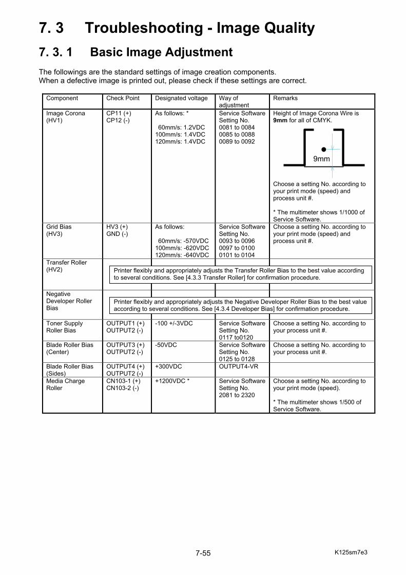
K125sm7e3 7-55
7. 3 Troubleshooting - Image Quality
7. 3. 1 Basic Image Adjustment The followings are the standard settings of image creation components. When a defective image is printed out, please check if these settings are correct.
Component Check Point Designated voltage Way of adjustment
Remarks
Image Corona (HV1)
CP11 (+) CP12 (-)
As follows: * 60mm/s: 1.2VDC
100mm/s: 1.4VDC 120mm/s: 1.4VDC
Service Software Setting No. 0081 to 0084 0085 to 0088 0089 to 0092
Height of Image Corona Wire is 9mm for all of CMYK. Choose a setting No. according to your print mode (speed) and process unit #. * The multimeter shows 1/1000 of Service Software.
Grid Bias (HV3)
HV3 (+) GND (-)
As follows: 60mm/s: -570VDC
100mm/s: -620VDC120mm/s: -640VDC
Service Software Setting No. 0093 to 0096 0097 to 0100 0101 to 0104
Choose a setting No. according to your print mode (speed) and process unit #.
Transfer Roller (HV2)
Negative Developer Roller Bias
Toner Supply Roller Bias
OUTPUT1 (+) OUTPUT2 (-)
-100 +/-3VDC Service Software Setting No. 0117 to0120
Choose a setting No. according to your process unit #.
Blade Roller Bias (Center)
OUTPUT3 (+) OUTPUT2 (-)
-50VDC Service Software Setting No. 0125 to 0128
Choose a setting No. according to your process unit #.
Blade Roller Bias (Sides)
OUTPUT4 (+) OUTPUT2 (-)
+300VDC OUTPUT4-VR
Media Charge Roller
CN103-1 (+) CN103-2 (-)
+1200VDC * Service Software Setting No. 2081 to 2320
Choose a setting No. according to your print mode (speed). * The multimeter shows 1/500 of Service Software.
9mm
Printer flexibly and appropriately adjusts the Transfer Roller Bias to the best value according to several conditions. See [4.3.3 Transfer Roller] for confirmation procedure.
Printer flexibly and appropriately adjusts the Negative Developer Roller Bias to the best value according to several conditions. See [4.3.4 Developer Bias] for confirmation procedure.

K125sm7e3 7-56
7. 3. 2 Cause of Frequent Image Problem If a defective image appears on the print frequently with keeping a constant interval, please check the length of interval to quickly find the suspicious part.
Interval Suspicious part 138mm Roller Developer 201mm Fusing Roller
209.4mm Belt Feed Roller 207mm Toner Supply Roller 251mm Drum 248mm Blade Roller
2,084mm Belt 110mm Transfer Roller
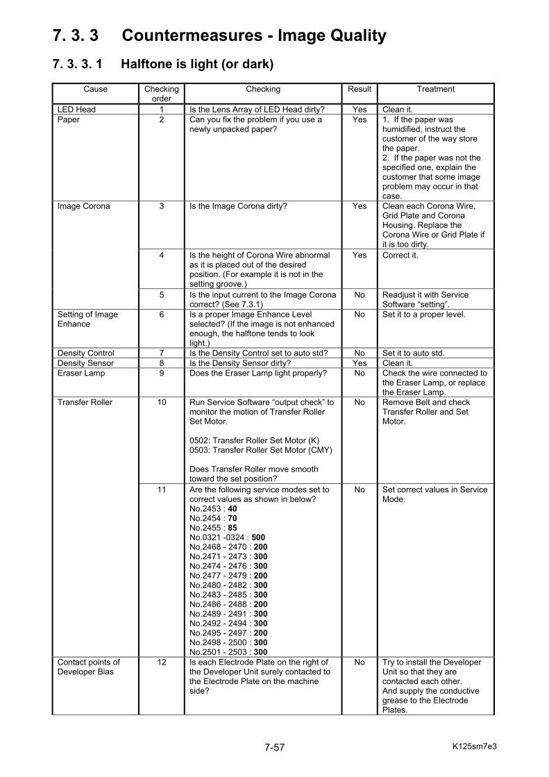
K125sm7e3 7-57
7. 3. 3 Countermeasures - Image Quality 7. 3. 3. 1 Halftone is light (or dark)
Cause Checking order
Checking Result Treatment
LED Head 1 Is the Lens Array of LED Head dirty? Yes Clean it. Paper 2 Can you fix the problem if you use a
newly unpacked paper? Yes 1. If the paper was
humidified, instruct the customer of the way store the paper. 2. If the paper was not the specified one, explain the customer that some image problem may occur in that case.
Image Corona 3 Is the Image Corona dirty? Yes Clean each Corona Wire, Grid Plate and Corona Housing. Replace the Corona Wire or Grid Plate if it is too dirty.
4 Is the height of Corona Wire abnormal as it is placed out of the desired position. (For example it is not in the setting groove.)
Yes Correct it.
5 Is the input current to the Image Corona correct? (See 7.3.1)
No Readjust it with Service Software “setting”.
Setting of Image Enhance
6 Is a proper Image Enhance Level selected? (If the image is not enhanced enough, the halftone tends to look light.)
No Set it to a proper level.
Density Control 7 Is the Density Control set to auto std? No Set it to auto std. Density Sensor 8 Is the Density Sensor dirty? Yes Clean it. Eraser Lamp 9 Does the Eraser Lamp light properly? No Check the wire connected to
the Eraser Lamp, or replace the Eraser Lamp.
Transfer Roller 10 Run Service Software “output check” to monitor the motion of Transfer Roller Set Motor. 0502: Transfer Roller Set Motor (K) 0503: Transfer Roller Set Motor (CMY) Does Transfer Roller move smooth toward the set position?
No Remove Belt and check Transfer Roller and Set Motor.
11 Are the following service modes set to correct values as shown in below? No.2453 : 40 No.2454 : 70 No.2455 : 85 No.0321 -0324 : 500 No.2468 - 2470 : 200 No.2471 - 2473 : 300 No.2474 - 2476 : 300 No.2477 - 2479 : 200 No.2480 - 2482 : 300 No.2483 - 2485 : 300 No.2486 - 2488 : 200 No.2489 - 2491 : 300 No.2492 - 2494 : 300 No.2495 - 2497 : 200 No.2498 - 2500 : 300 No.2501 - 2503 : 300
No Set correct values in Service Mode.
Contact points of Developer Bias
12 Is each Electrode Plate on the right of the Developer Unit surely contacted to the Electrode Plate on the machine side?
No Try to install the Developer Unit so that they are contacted each other. And supply the conductive grease to the Electrode Plates.

K125sm7e3 7-58
Set position of Developer Unit
13 Is the excentric cam (Developer Press Cam) stayed at the correct position with pressing the Developer Unit to the Drum?
No Check its driving mechanism and motor.
Developer Unit 14 Is Roller Developer evenly covered with the toner?
No Overhaul the Developer and find the cause.
HVP 15 Is proper voltage supplied to each roller of the Developer Unit?
No Adjust the voltage properly.
Developer Bias 16 Temporarily set Density Control to OFF. Find a proper Developer Bias. Does the print obtain enough Optical Density?
Yes Perform Density Lock. (See 9.1)
Main Control PCB (PW12520)
17 Can the problem be fixed by replacing the Main PCB?
Yes OK
Drum 18 Can the problem be fixed by replacing the Drum?
Yes OK
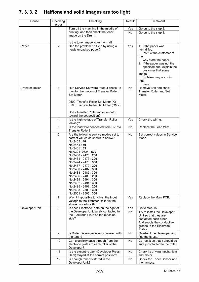
K125sm7e3 7-59
7. 3. 3. 2 Halftone and solid images are too light
Cause Checking order
Checking Result Treatment
1 Turn off the machine in the middle of printing, and then check the toner image on the Drum. Is the toner image looks normal?
Yes Go on to the step 3. No Go on to the step 8.
Paper 2 Can the problem be fixed by using a newly unpacked paper?
Yes 1. If the paper was humidified, instruct the customer of the way store the paper. 2. If the paper was not the specified one, explain the customer that some image problem may occur in that case.
Transfer Roller 3 Run Service Software “output check” to monitor the motion of Transfer Roller Set Motor. 0502: Transfer Roller Set Motor (K) 0503: Transfer Roller Set Motor (CMY) Does Transfer Roller move smooth toward the set position?
No Remove Belt and check Transfer Roller and Set Motor.
4 Is the high voltage of Transfer Roller leaking?
Yes Check the wiring.
5 Is the lead wire connected from HVP to Transfer Roller?
No Replace the Lead Wire.
6 Are the following service modes set to correct values as shown in below? No.2453 : 40 No.2454 : 70 No.2455 : 85 No.0321 -0324 : 500 No.2468 - 2470 : 200 No.2471 - 2473 : 300 No.2474 - 2476 : 300 No.2477 - 2479 : 200 No.2480 - 2482 : 300 No.2483 - 2485 : 300 No.2486 - 2488 : 200 No.2489 - 2491 : 300 No.2492 - 2494 : 300 No.2495 - 2497 : 200 No.2498 - 2500 : 300 No.2501 - 2503 : 300
No Set correct values in Service Mode.
7 Was it impossible to adjust the input voltage to the Transfer Roller in the above procedure 6?
Yes Replace the Main PCB.
Developer Unit 8 Is each Electrode Plate on the right of the Developer Unit surely contacted to the Electrode Plate on the machine side?
Yes Go to step 15. No Try to install the Developer
Unit so that they are contacted each other. And supply the conductive grease to the Electrode Plates.
9 Is Roller Developer evenly covered with the toner?
No Overhaul the Developer and find the cause.
10 Can electricity pass through from the electrode plates to each roller of the Developer?
No Correct it so that it should be surely contacted to the roller.
11 Is the excentric cam (Developer Press Cam) stayed at the correct position?
No Check its driving mechanism and motor.
12 Is enough toner is stored in the Developer Unit?
No Check the Toner Sensor and the harness.
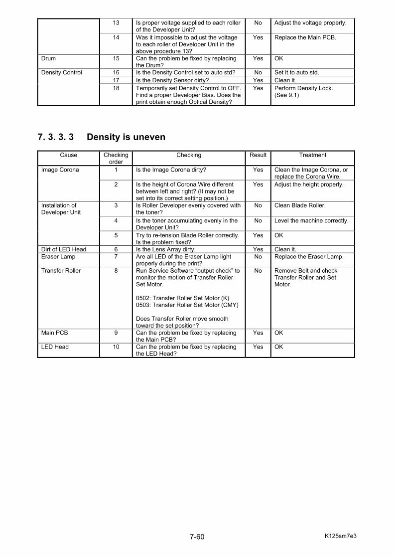
K125sm7e3 7-60
13 Is proper voltage supplied to each roller of the Developer Unit?
No Adjust the voltage properly.
14 Was it impossible to adjust the voltage to each roller of Developer Unit in the above procedure 13?
Yes Replace the Main PCB.
Drum 15 Can the problem be fixed by replacing the Drum?
Yes OK
Density Control 16 Is the Density Control set to auto std? No Set it to auto std. 17 Is the Density Sensor dirty? Yes Clean it. 18 Temporarily set Density Control to OFF.
Find a proper Developer Bias. Does the print obtain enough Optical Density?
Yes Perform Density Lock. (See 9.1)
7. 3. 3. 3 Density is uneven
Cause Checking order
Checking Result Treatment
Image Corona 1 Is the Image Corona dirty? Yes Clean the Image Corona, or replace the Corona Wire.
2 Is the height of Corona Wire different between left and right? (It may not be set into its correct setting position.)
Yes Adjust the height properly.
Installation of Developer Unit
3 Is Roller Developer evenly covered with the toner?
No Clean Blade Roller.
4 Is the toner accumulating evenly in the Developer Unit?
No Level the machine correctly.
5 Try to re-tension Blade Roller correctly. Is the problem fixed?
Yes OK
Dirt of LED Head 6 Is the Lens Array dirty Yes Clean it. Eraser Lamp 7 Are all LED of the Eraser Lamp light
properly during the print? No Replace the Eraser Lamp.
Transfer Roller 8 Run Service Software “output check” to monitor the motion of Transfer Roller Set Motor. 0502: Transfer Roller Set Motor (K) 0503: Transfer Roller Set Motor (CMY) Does Transfer Roller move smooth toward the set position?
No Remove Belt and check Transfer Roller and Set Motor.
Main PCB 9 Can the problem be fixed by replacing the Main PCB?
Yes OK
LED Head 10 Can the problem be fixed by replacing the LED Head?
Yes OK
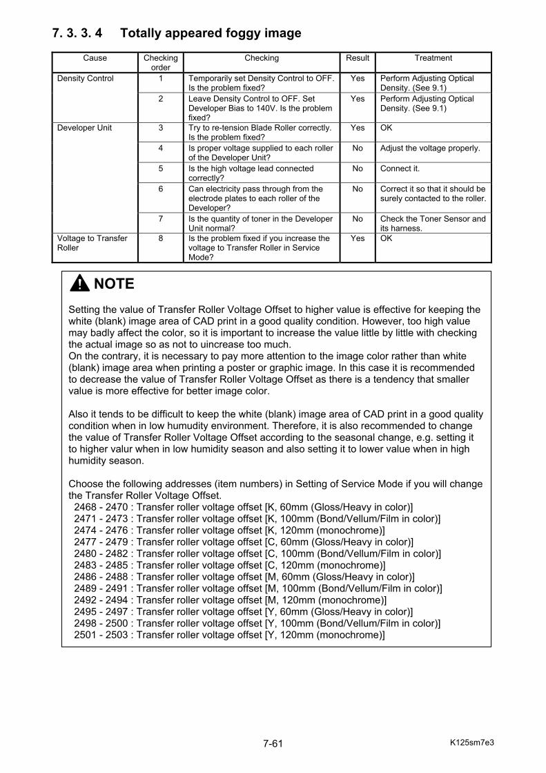
K125sm7e3 7-61
7. 3. 3. 4 Totally appeared foggy image
Cause Checking order
Checking Result Treatment
Density Control 1 Temporarily set Density Control to OFF. Is the problem fixed?
Yes Perform Adjusting Optical Density. (See 9.1)
2 Leave Density Control to OFF. Set Developer Bias to 140V. Is the problem fixed?
Yes Perform Adjusting Optical Density. (See 9.1)
Developer Unit 3 Try to re-tension Blade Roller correctly. Is the problem fixed?
Yes OK
4 Is proper voltage supplied to each roller of the Developer Unit?
No Adjust the voltage properly.
5 Is the high voltage lead connected correctly?
No Connect it.
6 Can electricity pass through from the electrode plates to each roller of the Developer?
No Correct it so that it should be surely contacted to the roller.
7 Is the quantity of toner in the Developer Unit normal?
No Check the Toner Sensor and its harness.
Voltage to Transfer Roller
8 Is the problem fixed if you increase the voltage to Transfer Roller in Service Mode?
Yes OK
NOTE Setting the value of Transfer Roller Voltage Offset to higher value is effective for keeping the white (blank) image area of CAD print in a good quality condition. However, too high value may badly affect the color, so it is important to increase the value little by little with checking the actual image so as not to uincrease too much. On the contrary, it is necessary to pay more attention to the image color rather than white (blank) image area when printing a poster or graphic image. In this case it is recommended to decrease the value of Transfer Roller Voltage Offset as there is a tendency that smaller value is more effective for better image color. Also it tends to be difficult to keep the white (blank) image area of CAD print in a good quality condition when in low humudity environment. Therefore, it is also recommended to change the value of Transfer Roller Voltage Offset according to the seasonal change, e.g. setting it to higher valur when in low humidity season and also setting it to lower value when in high humidity season. Choose the following addresses (item numbers) in Setting of Service Mode if you will change the Transfer Roller Voltage Offset. 2468 - 2470 : Transfer roller voltage offset [K, 60mm (Gloss/Heavy in color)] 2471 - 2473 : Transfer roller voltage offset [K, 100mm (Bond/Vellum/Film in color)] 2474 - 2476 : Transfer roller voltage offset [K, 120mm (monochrome)] 2477 - 2479 : Transfer roller voltage offset [C, 60mm (Gloss/Heavy in color)] 2480 - 2482 : Transfer roller voltage offset [C, 100mm (Bond/Vellum/Film in color)] 2483 - 2485 : Transfer roller voltage offset [C, 120mm (monochrome)] 2486 - 2488 : Transfer roller voltage offset [M, 60mm (Gloss/Heavy in color)] 2489 - 2491 : Transfer roller voltage offset [M, 100mm (Bond/Vellum/Film in color)] 2492 - 2494 : Transfer roller voltage offset [M, 120mm (monochrome)] 2495 - 2497 : Transfer roller voltage offset [Y, 60mm (Gloss/Heavy in color)] 2498 - 2500 : Transfer roller voltage offset [Y, 100mm (Bond/Vellum/Film in color)] 2501 - 2503 : Transfer roller voltage offset [Y, 120mm (monochrome)]

K125sm7e3 7-62
7. 3. 3. 5 Vertical thick line that looks not clear
Cause Checking order
Checking Result Treatment
Image Corona 1 Is the Image Corona dirty? Yes Clean each Corona Wire, Grid Plate and Corona Housing. Replace the Corona Wire or Grid Plate if it is too dirty.
2 Is the Wire Cleaner placed at the end of the unit?
No Check if there is any abnormality on the driving mechanism of Wire Cleaner, such as the breakage of Wire Cleaning Motor or distortion of sender shaft.
3 Is the wire cleaning operation completed within 90 seconds?
No Check if there is any abnormality on the driving mechanism of Wire Cleaner, such as the breakage of Wire Cleaning Motor or distortion of sender shaft.
Developer Unit 4 Is Roller Developer evenly covered with the toner?
No Overhaul the Developer Unit and check is there is any reason for this problem.
5 Is the Blade Roller dirty? Yes Reseat Blade in Developer Unit.
Drum Cleaner Unit 6 Is the Drum dirty? Yes Reseat Blade in Drum Cleaner, or use a new Drum Cleaner Unit.
LED Head 7 Is the LED Head dirty? Yes Clean it. Belt Cleaner Unit 8 Is the Belt dirty? Yes Reseat Blade in Belt
Cleaner, or use a new Belt Cleaner Unit.
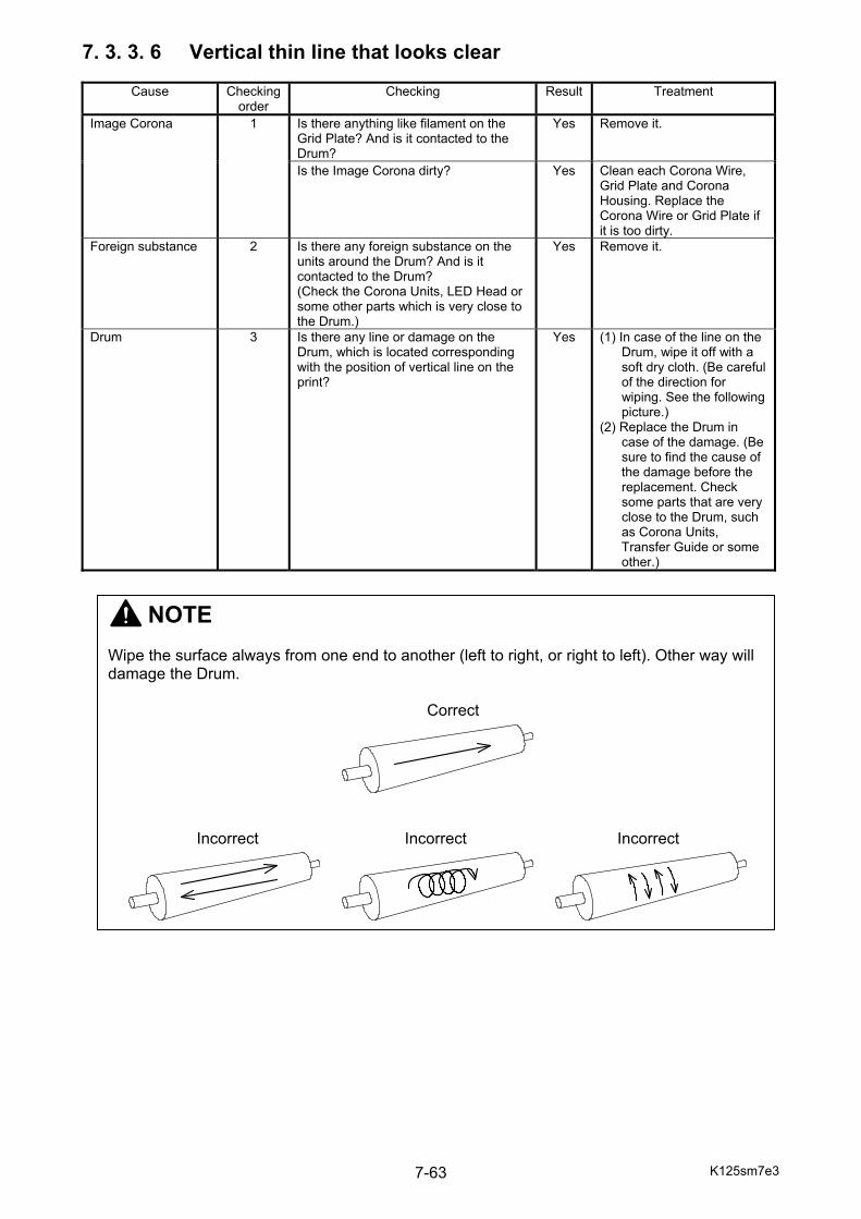
K125sm7e3 7-63
7. 3. 3. 6 Vertical thin line that looks clear
Cause Checking order
Checking Result Treatment
Image Corona 1 Is there anything like filament on the Grid Plate? And is it contacted to the Drum?
Yes Remove it.
Is the Image Corona dirty? Yes Clean each Corona Wire, Grid Plate and Corona Housing. Replace the Corona Wire or Grid Plate if it is too dirty.
Foreign substance 2 Is there any foreign substance on the units around the Drum? And is it contacted to the Drum? (Check the Corona Units, LED Head or some other parts which is very close to the Drum.)
Yes Remove it.
Drum 3 Is there any line or damage on the Drum, which is located corresponding with the position of vertical line on the print?
Yes (1) In case of the line on the Drum, wipe it off with a soft dry cloth. (Be careful of the direction for wiping. See the following picture.) (2) Replace the Drum in case of the damage. (Be sure to find the cause of the damage before the replacement. Check some parts that are very close to the Drum, such as Corona Units, Transfer Guide or some other.)
NOTE Wipe the surface always from one end to another (left to right, or right to left). Other way will damage the Drum. Correct Incorrect Incorrect Incorrect
K125sm7e3 7-64
7. 3. 3. 7 Vertical white line
Cause Checking order
Checking Result Treatment
Image Corona 1 Is there anything like filament on the Grid Plate? And is it contacted to the Drum?
Yes Remove it.
Dirt of the LED Head
2 Is the Lens Array of LED Head dirty? Yes Clean it with a soft dry cloth or lens cleaning cloth (paper).
Transfer Roller 3 Open the Rear Door while printing by intension. Is there any “no transferred” image area on the media even the Drum has toner image?
Yes Check for damage on the surface of Transfer Roller and Belt. Remove any cause of the damage, and then replace it.
Entrance of Fuser Unit
4 Is there any foreign substance or dirt around the entrance area of the Fuser Unit? And is it touching on unfused image side of the media?
Yes Clean it off
Drum 5 Is there any damage on the Drum, which is located corresponding with the position of white line on the print?
Yes Find the cause for the damage, remove the cause, and replace the Drum. (Please check some parts that are very close to the Drum, such as Corona Units, Transfer Guide or some other.)
LED Head 6 Can the problem be fixed by replacing the LED Head?
Yes OK
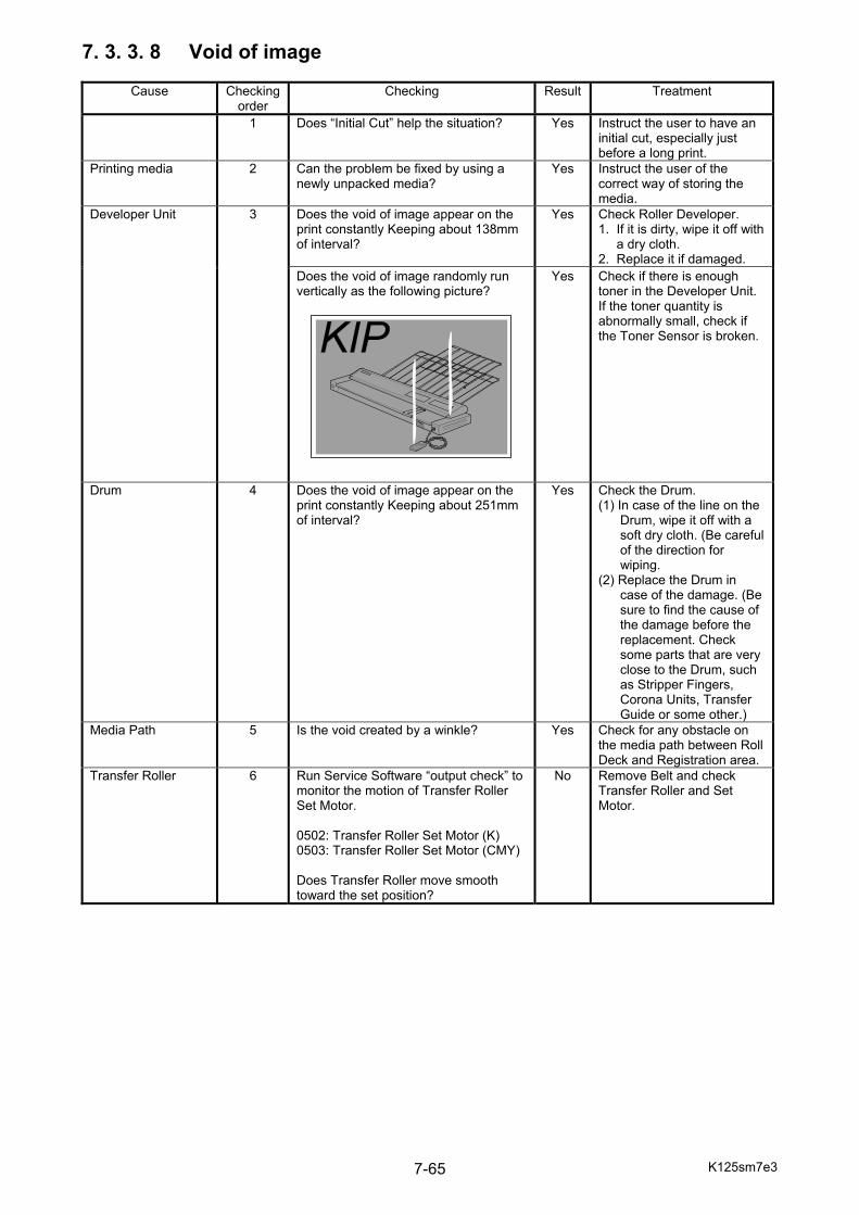
K125sm7e3 7-65
7. 3. 3. 8 Void of image
Cause Checking order
Checking Result Treatment
1 Does “Initial Cut” help the situation? Yes Instruct the user to have an initial cut, especially just before a long print.
Printing media 2 Can the problem be fixed by using a newly unpacked media?
Yes Instruct the user of the correct way of storing the media.
Developer Unit 3 Does the void of image appear on the print constantly Keeping about 138mm of interval?
Yes Check Roller Developer. 1. If it is dirty, wipe it off with a dry cloth. 2. Replace it if damaged.
Does the void of image randomly run vertically as the following picture?
Yes Check if there is enough toner in the Developer Unit. If the toner quantity is abnormally small, check if the Toner Sensor is broken.
Drum 4 Does the void of image appear on the print constantly Keeping about 251mm of interval?
Yes Check the Drum. (1) In case of the line on the Drum, wipe it off with a soft dry cloth. (Be careful of the direction for wiping. (2) Replace the Drum in case of the damage. (Be sure to find the cause of the damage before the replacement. Check some parts that are very close to the Drum, such as Stripper Fingers, Corona Units, Transfer Guide or some other.)
Media Path 5 Is the void created by a winkle? Yes Check for any obstacle on the media path between Roll Deck and Registration area.
Transfer Roller 6 Run Service Software “output check” to monitor the motion of Transfer Roller Set Motor. 0502: Transfer Roller Set Motor (K) 0503: Transfer Roller Set Motor (CMY) Does Transfer Roller move smooth toward the set position?
No Remove Belt and check Transfer Roller and Set Motor.

K125sm7e3 7-66
7. 3. 3. 9 Dirt on the back of the print
Cause Checking order
Checking Result Treatment
Media feeding area 1 Is there any suspicious dirt on the Roll Deck or Bypass Feeder?
Yes Clean it, and also find the cause of this dirt.
Belt 2 Is the Waste Toner Box (Belt) full? Yes Replace it. 3 Is the Belt dirty? Yes Reseat Blade in Belt
Cleaner, or use a new Belt Cleaner Unit.
Fuser Unit 4 Is the Fuser Entrance Guide dirty? Yes Clean it. 5 Is there a melt toner around the fuser
exit, such as Fuser Roller, Pressure Roller, fingers and other parts?
Yes Clean it off.
6 IS the Web Cleaner correctly set? No Reseat it. 7. 3. 3. 10 Poor fusing
Cause Checking order
Checking Result Treatment
Paper 1 Is the selection of media type on the Media Selector and the actual media type correctly matched with each other?
No Instruct the user to set the Media Selector correctly.
2 Can the problem be fixed by using a newly unpacked paper?
Yes 1. Instruct the user of the correct way of storing the media. 2. If the media is not a recommended one, explain the user that some image problem may occur in that case.
Fusing temperature setting
3 Run Service Software “data display” to monitor the Thermisters. 0001: fuser temperature #1 (Sides) 0002: fuser temperature #2 (Center) Is the detected temperature correct?
No Go to [7.2.2 09-00 Fuser Temperature Rising Error].
4 Run Service Software “setting” to check the current setting value for Fuser Temperature according to media type. Is the setting temperature correct?
No Set the fuser temperature correctly.
5 Is the pressure provided by the Pressure Roller correct?
No Adjust it correctly. See the figure below.
10mm 10mm
10mm 8mm 10mm
60mm/s 100mm/s 120mm/sPlain 145 155 160 Vellum 145 155 160 Film 130 140 145 Gross 145 155 160 Heavy 150 160 170
K125sm7e3 7-67
7. 3. 3. 11 Complete white (No image)
Cause Checking order
Checking Result Treatment
1 Is the LED Head set to operation position?
No Open the Left Side Door, turn the LED Head Release Lever to operation position and then secure the lever with the bracket.
Transfer Roller 2 Open the Rear Door while printing by intension. Does the Drum has toner image?
Yes Go to step 3 No Go to step 4
Transfer Roller and HVP
3 Check the voltage between the pin of orange wire of CN301 on the HVP and the ground. Is 24V supplied when the printer is ready?
No Check the Fuse. (K): F1 (C): F2 (M): F3 (Y): F4
Check the voltage between the 2nd pin of CN302 on the HVP and the ground. Is the voltage “L” during printing?
No Check the input harness from the Main PCB to the HVP.
Run Service Software “output check” to monitor the motion of Transfer Roller Set Motor. 0502: Transfer Roller Set Motor (K) 0503: Transfer Roller Set Motor (CMY) Does Transfer Roller move smooth toward the set position?
No Remove Belt and check Transfer Roller and Set Motor.
Is the high voltage lead line connected? No Connect it. Is the high voltage lead broken? Yes Replace it.
LED Head 4 Try to replace the connections of flat cables of suspected LED Head and correct one. Does the “correct” LED Head come to have the problem while the “suspected” one no longer has the problem?
Yes Replace the “suspected” LED Head.
No Replace the Main PCB.
Developer Unit 5 Is the excentric cam (Developer Press Cam) stayed at the correct position with pressing the Developer Unit to the Drum?
No Check its driving mechanism and motor.
6 Is Roller Developer evenly covered with the toner?
No Overhaul the Developer and find the cause.
7 Check the voltage between the 4th pin of CN302 on the HVP and the ground. Is the voltage “L” during printing?
No Check the input harness from the Main PCB to the HVP.
8 Is proper voltage supplied to each roller of the Developer Unit?
No Adjust the voltage properly.
9 Is the high voltage lead line connected? No Connect it. 10 Is the high voltage lead broken? Yes Replace it.
K125sm7e3 7-68
7. 3. 3. 12 Blur on dark image
Cause Checking order
Checking Result Treatment
Media 1 Does the media type selection match the actual media?
No Set it accordingly.
2 Can the problem be fixed by using a newly unpacked paper?
Yes 1. Instruct the user of the correct way of storing the media. 2. If the media is not a recommended one, explain the user that some image problem may occur in that case.
LED Head 3 Is the LED Head set to operation position?
No Open the Left Side Door, turn the LED Head Release Lever to operation position and then secure the lever with the bracket.
Fuser Temperature 4 Is the fuser temperature setting set correctly according to the selected media?
No Set it accordingly.
7. 3. 3. 13 Complete solid image like “all black”
Cause Checking order
Checking Result Treatment
1 Is the print provided with side margin? Yes Go to step 2 No No margin, go to step 3
LED Head or Main PCB
2 Try to replace the LED Head of defective color with the one of another color without problem. Does the problem come to occur on the replaced color?
Yes Replace the LED Head. No Replace the Main PCB.
Image Corona and HVP
3 Check the voltage between the pin of orange wire of CN301 on the HVP and the ground. Is 24V supplied when the printer is ready?
No Check the Fuse PCB.
4 Check the voltage between the 1st pin of CN302 on the HVP and the ground. Is the voltage “L” during printing?
No Check the input harness from the Main PCB to the HVP.
5 Is the input current to the Image Corona correct? (See 7.3.1)
No If 0V, replace HVP. Readjust it with Service Software “setting”.
6 Is the Corona Wire dirty? Yes Clean it. Replace if too dirty.7 Is the tension of Corona Wire proper? No Give a proper tension. 8 Is the high voltage lead line connected? No Connect it. 9 Is the high voltage lead broken? Yes Replace it.
10 Measure the resistance between the Corona Rail and the ground. Is it 0 ohm? (Normally it is overload)
Yes Leak is occurred on the Corona Rail. (1) Check if there is any foreign substance on the Corona Rail. (2) Check is any harness is broken.

K125sm7e3 7-69
7. 3. 4 Checking for correct pressurization or Developer Several image quality defects may possibly happen if the pressurization of Developer Unit is not correctly accomplished. Please take the following 4 types of checking and be sure that all requirements must be satisfied. Check 1 Draw out the Process Unit and bring up both Drum and Cleaner Unit in the direction of arrows. Rotate the Coupling on the right by hand to manually drive the Developer Pressurization mechanism, which moves the Developer Unit forward and backward. Be sure that the movement of Developer Unit is smooth without abnormal stress.
Coupling
Movement of developer must be smooth
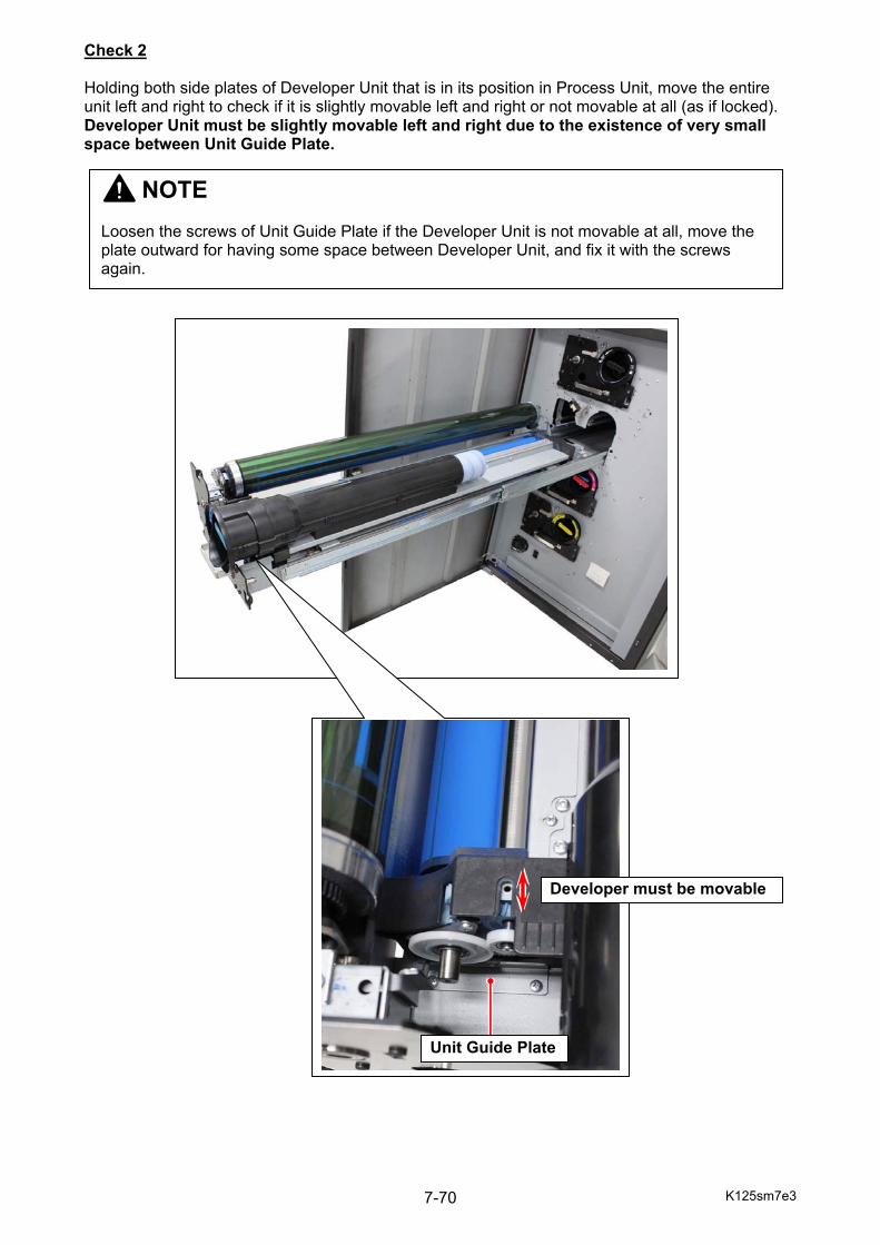
K125sm7e3 7-70
Check 2 Holding both side plates of Developer Unit that is in its position in Process Unit, move the entire unit left and right to check if it is slightly movable left and right or not movable at all (as if locked). Developer Unit must be slightly movable left and right due to the existence of very small space between Unit Guide Plate.
Unit Guide Plate
NOTE Loosen the screws of Unit Guide Plate if the Developer Unit is not movable at all, move the plate outward for having some space between Developer Unit, and fix it with the screws again.
Developer must be movable
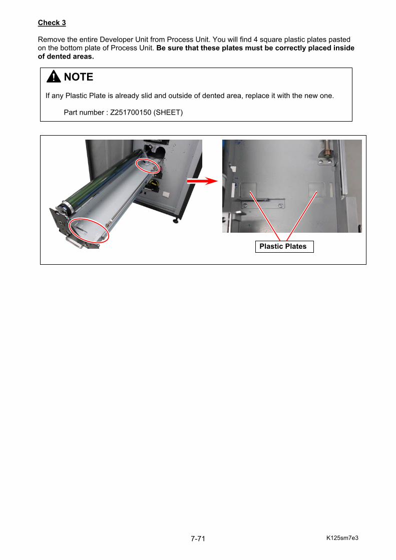
K125sm7e3 7-71
Check 3 Remove the entire Developer Unit from Process Unit. You will find 4 square plastic plates pasted on the bottom plate of Process Unit. Be sure that these plates must be correctly placed inside of dented areas.
Plastic Plates
NOTE If any Plastic Plate is already slid and outside of dented area, replace it with the new one. Part number : Z251700150 (SHEET)
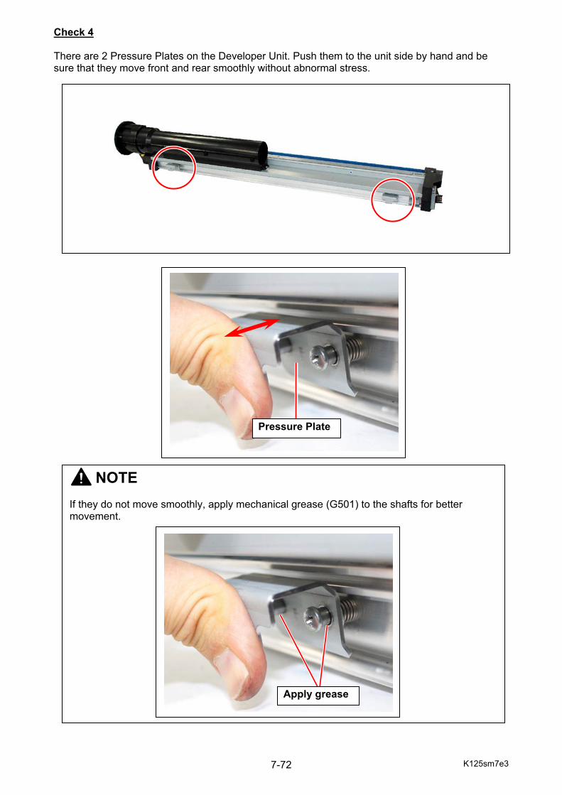
K125sm7e3 7-72
Check 4 There are 2 Pressure Plates on the Developer Unit. Push them to the unit side by hand and be sure that they move front and rear smoothly without abnormal stress.
Pressure Plate
NOTE If they do not move smoothly, apply mechanical grease (G501) to the shafts for better movement.
Apply grease
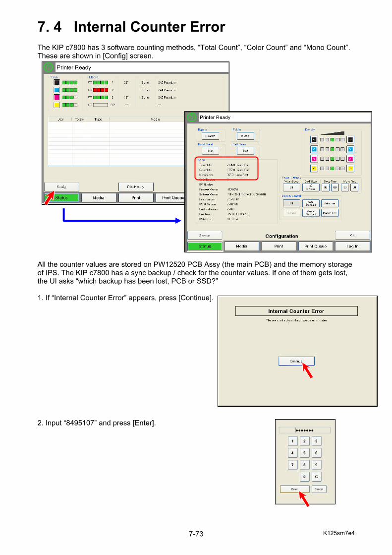
K125sm7e4 7-73
7. 4 Internal Counter Error The KIP c7800 has 3 software counting methods, “Total Count”, “Color Count” and “Mono Count”. These are shown in [Config] screen. All the counter values are stored on PW12520 PCB Assy (the main PCB) and the memory storage of IPS. The KIP c7800 has a sync backup / check for the counter values. If one of them gets lost, the UI asks “which backup has been lost, PCB or SSD?” 1. If “Internal Counter Error” appears, press [Continue]. 2. Input “8495107” and press [Enter].
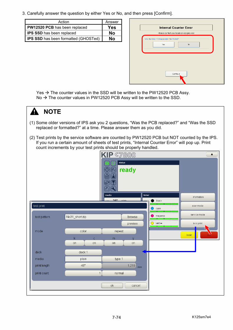
K125sm7e4 7-74
3. Carefully answer the question by either Yes or No, and then press [Confirm]. Yes The counter values in the SSD will be written to the PW12520 PCB Assy. No The counter values in PW12520 PCB Assy will be written to the SSD.
Action AnswerPW12520 PCB has been replaced Yes IPS SSD has been replaced No IPS SSD has been formatted (GHOSTed) No
NOTE (1) Some older versions of IPS ask you 2 questions, “Was the PCB replaced?” and “Was the SSD
replaced or formatted?” at a time. Please answer them as you did. (2) Test prints by the service software are counted by PW12520 PCB but NOT counted by the IPS.
If you run a certain amount of sheets of test prints, “Internal Counter Error” will pop up. Print count increments by your test prints should be properly handled.
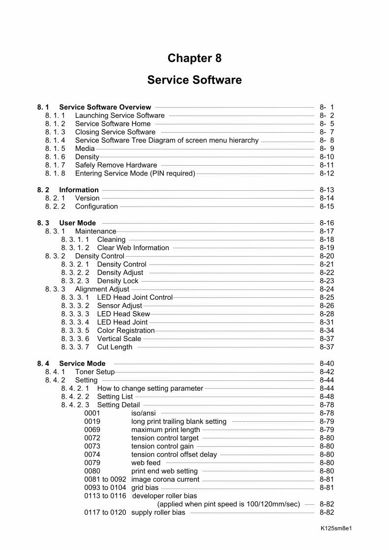
K125sm8e1
Chapter 8
Service Software 8. 1 Service Software Overview 8- 1 8. 1. 1 Launching Service Software 8- 2 8. 1. 2 Service Software Home 8- 5 8. 1. 3 Closing Service Software 8- 7 8. 1. 4 Service Software Tree Diagram of screen menu hierarchy 8- 8 8. 1. 5 Media 8- 9 8. 1. 6 Density 8-10 8. 1. 7 Safely Remove Hardware 8-11 8. 1. 8 Entering Service Mode (PIN required) 8-12 8. 2 Information 8-13 8. 2. 1 Version 8-14 8. 2. 2 Configuration 8-15 8. 3 User Mode 8-16 8. 3. 1 Maintenance 8-17 8. 3. 1. 1 Cleaning 8-18 8. 3. 1. 2 Clear Web Information 8-19 8. 3. 2 Density Control 8-20 8. 3. 2. 1 Density Control 8-21 8. 3. 2. 2 Density Adjust 8-22 8. 3. 2. 3 Density Lock 8-23 8. 3. 3 Alignment Adjust 8-24 8. 3. 3. 1 LED Head Joint Control 8-25 8. 3. 3. 2 Sensor Adjust 8-26 8. 3. 3. 3 LED Head Skew 8-28 8. 3. 3. 4 LED Head Joint 8-31 8. 3. 3. 5 Color Registration 8-34 8. 3. 3. 6 Vertical Scale 8-37 8. 3. 3. 7 Cut Length 8-37 8. 4 Service Mode 8-40 8. 4. 1 Toner Setup 8-42 8. 4. 2 Setting 8-44 8. 4. 2. 1 How to change setting parameter 8-44 8. 4. 2. 2 Setting List 8-48 8. 4. 2. 3 Setting Detail 8-78 0001 iso/ansi 8-78 0019 long print trailing blank setting 8-79 0069 maximum print length 8-79 0072 tension control target 8-80 0073 tension control gain 8-80 0074 tension control offset delay 8-80 0079 web feed 8-80 0080 print end web setting 8-80 0081 to 0092 image corona current 8-81 0093 to 0104 grid bias 8-81 0113 to 0116 developer roller bias (applied when pint speed is 100/120mm/sec) 8-82 0117 to 0120 supply roller bias 8-82
K124sm8e1
0125 to 0128 blade roller bias (applied when pint speed is 100/120mm/sec) 8-82 0139 to 0142 developer roller bias offset (applied when pint speed is 60mm/sec) 8-83 0143 to 0146 blade roller bias (applied when pint speed is 60mm/sec) 8-83 0201 flapper control solenoid pwm duty (long print) 8-83 0202 tension control target (long print) 8-84 0203 lower transfer tension control target 8-84 0204 lower transfer tension control gain 8-84 0205 mono print feed mode 8-85 0206 stacker select 8-85 0207 to 0226 flapper control solenoid pwm duty 8-86 0229 long print control change point 8-86 0241 image position vertical 8-87 0242 image position horizontal 8-87 0243 to 0250 led head joint horizontal 8-88 0251 to 0262 led head skew 8-89 0264 trailing image mask area 8-90 0265 leading image mask area 8-90 0293 to 0296 color registration horizontal 8-91 0302 / 0305 / 0308 / 0311 color registration vertical 8-92 0301 / 0303 / 0304 / 0306 / 0307 / 0309 / 0310 / 0312 led head joint vertical 8-93 0316 to 0319 color registration vertical offset 8-94 0321 to 0324 transfer roller current 8-94 0325 to 0327 transfer roller voltage select 8-94 0361 counter-a config 8-95 0362 counter-b config 8-95 0363 counter-a data 8-95 0366 counter-b data 8-95 0369 total counter data 8-95
0441 to 0456 transfer roller voltage (K, 60mm/s plain) 8-96 0457 to 0472 transfer roller voltage (K, 60mm/s tracing) 8-96 0473 to 0488 transfer roller voltage (K, 60mm/s film) 8-97 0489 to 0504 transfer roller voltage (K, 60mm/s gloss) 8-97 0505 to 0520 transfer roller voltage (K, 60mm/s heavy) 8-97 0521 to 0536 transfer roller voltage (K, 100mm/s plain) 8-98 0537 to 0552 transfer roller voltage (K, 100mm/s tracing) 8-98 0553 to 0568 transfer roller voltage (K, 100mm/s film) 8-99 0569 to 0584 transfer roller voltage (K, 100mm/s gloss) 8-99 0585 to 0600 transfer roller voltage (K, 100mm/s heavy) 8-99 0601 to 0616 transfer roller voltage (K, 120mm/s plain) 8-100 0617 to 0632 transfer roller voltage (K, 120mm/s tracing) 8-100 0633 to 0648 transfer roller voltage (K, 120mm/s film) 8-101 0649 to 0664 transfer roller voltage (K, 120mm/s gloss) 8-101 0665 to 0680 transfer roller voltage (K, 120mm/s heavy) 8-101 0681 to 0696 transfer roller voltage (C, 60mm/s plain) 8-102 0697 to 0712 transfer roller voltage (C, 60mm/s tracing) 8-102 0713 to 0728 transfer roller voltage (C, 60mm/s film) 8-103 0729 to 0744 transfer roller voltage (C, 60mm/s gloss) 8-103 0745 to 0760 transfer roller voltage (C, 60mm/s heavy) 8-103 0761 to 0776 transfer roller voltage (C, 100mm/s plain) 8-104 0777 to 0792 transfer roller voltage (C, 100mm/s tracing) 8-104 0793 to 0800, 1481 to 1488 transfer roller voltage (C, 100mm/s film) 8-105
0801 to 0812 light intensity correction 8-105 0813 to 0816 light gain 8-106 0844 to 0852 deck motor 8-106 0853 to 0855 lower transfer motor 8-106 0917 to 0919 cut length fine (deck #1-3) 8-107

K124sm8e1
0920 time of developer reset control - after print 8-107 1401 to 1470 image enhance table 8-108
1489 to 1504 transfer roller voltage (C, 100mm/s gloss) 8-110 1505 to 1520 transfer roller voltage (C, 100mm/s heavy) 8-110 1521 to 1536 transfer roller voltage (C, 120mm/s plain) 8-111 1537 to 1552 transfer roller voltage (C, 120mm/s tracing) 8-111 1553 to 1568 transfer roller voltage (C, 120mm/s film) 8-112 1569 to 1584 transfer roller voltage (C, 120mm/s gloss) 8-112 1585 to 1600 transfer roller voltage (C, 120mm/s heavy) 8-112 1601 to 1616 transfer roller voltage (M, 60mm/s plain) 8-113 1617 to 1632 transfer roller voltage (M, 60mm/s tracing) 8-113 1633 to 1648 transfer roller voltage (M, 60mm/s film) 8-114 1649 to 1664 transfer roller voltage (M, 60mm/s gloss) 8-114 1665 to 1680 transfer roller voltage (M, 60mm/s heavy) 8-114 1681 to 1696 transfer roller voltage (M, 100mm/s plain) 8-115 1697 to 1712 transfer roller voltage (M, 100mm/s tracing) 8-115 1713 to 1728 transfer roller voltage (M, 100mm/s film) 8-116 1729 to 1744 transfer roller voltage (M, 100mm/s gloss) 8-116 1745 to 1760 transfer roller voltage (M, 100mm/s heavy) 8-116 1761 to 1776 transfer roller voltage (M, 120mm/s plain) 8-117 1777 to 1792 transfer roller voltage (M, 120mm/s tracing) 8-117 1793 to 1808 transfer roller voltage (M, 120mm/s film) 8-118 1809 to 1824 transfer roller voltage (M, 120mm/s gloss) 8-118 1825 to 1840 transfer roller voltage (M, 120mm/s heavy) 8-118 1841 to 1856 transfer roller voltage (Y, 60Ym/s plain) 8-119 1857 to 1872 transfer roller voltage (Y, 60mm/s tracing) 8-119 1873 to 1888 transfer roller voltage (Y, 60mm/s film) 8-120 1889 to 1904 transfer roller voltage (Y, 60mm/s gloss) 8-120 1905 to 1920 transfer roller voltage (Y, 60mm/s heavy) 8-120 1921 to 1936 transfer roller voltage (Y, 100mm/s plain) 8-121 1937 to 1952 transfer roller voltage (Y, 100mm/s tracing) 8-121 1953 to 1968 transfer roller voltage (Y, 100mm/s film) 8-122 1969 to 1984 transfer roller voltage (Y, 100mm/s gloss) 8-122 1985 to 2000 transfer roller voltage (Y, 100mm/s heavy) 8-122 2001 to 2016 transfer roller voltage (Y, 120mm/s plain) 8-123 2017 to 2032 transfer roller voltage (Y, 120mm/s tracing) 8-123 2033 to 2048 transfer roller voltage (Y, 120mm/s film) 8-124 2049 to 2064 transfer roller voltage (Y, 120mm/s gloss) 8-124 2065 to 2080 transfer roller voltage (Y, 120mm/s heavy) 8-124 2081 to 2096 media charge roller voltage (60mm/s plain) 8-125 2097 to 2112 media charge roller voltage (60mm/s tracing) 8-125 2113 to 2128 media charge roller voltage (60mm/s film) 8-126 2129 to 2144 media charge roller voltage (60mm/s gloss) 8-126 2145 to 2160 media charge roller voltage (60mm/s heavy) 8-126 2161 to 2176 media charge roller voltage (100mm/s plain) 8-127 2177 to 2192 media charge roller voltage (100mm/s tracing) 8-127 2193 to 2208 media charge roller voltage (100mm/s film) 8-128 2209 to 2224 media charge roller voltage (100mm/s gloss) 8-128 2225 to 2240 media charge roller voltage (100mm/s heavy) 8-128 2241 to 2256 media charge roller voltage (120mm/s plain) 8-129 2257 to 2272 media charge roller voltage (120mm/s tracing) 8-129 2273 to 2288 media charge roller voltage (120mm/s film) 8-130 2289 to 2304 media charge roller voltage (120mm/s gloss) 8-130 2305 to 2320 media charge roller voltage (120mm/s heavy) 8-130
2321 to 2340 fuser temp (60mm/s) 8-131 2341 to 2360 fuser temp (100mm/s) 8-131 2361 to 2380 fuser temp (120mm/s) 8-132 2453 to 2455 auto adjust transfer voltage target current 8-132 2468 to 2503 transfer roller voltage offset 8-133 8. 4. 3 Data Display 8-134

K124sm8e1
8. 4. 3. 1 Data Display List 8-134 8. 4. 4 Input Check 8-136 8. 4. 4. 1 Signal List 8-137 8. 4. 5 Output Check 8-140 8. 4. 5. 1 How to select item to operate 8-140 8. 4. 5. 2 Component List 8-142 8. 4. 6 Error History 8-143 8. 4. 6. 1 How to see Error History 8-143 8. 4. 6. 2 How to clear Error History 8-144 8. 4. 7 Jam History 8-145 8. 4. 7. 1 How to see Jam History 8-145 8. 4. 7. 2 How to clear Jam History 8-146 8. 4. 8 Backup Data 8-147 8. 4. 8. 1 How to backup printer setting 8-147 8. 4. 8. 2 How to restore printer setting 8-150 8. 4. 9 Program Update 8-153 8. 4. 9. 1 How to send program file to printer 8-153 8. 4. 10 Change Password 8-157 8. 5 Test Print 8-158 8. 5. 1 How to use technical Test Print 8-161

K125sm8e2 8-1
8. 1 Service Software Overview “Service Software" is an integrated utility application that provides intuitive operability by using Touchscreen. Service Software is pre-installed to the embedded controller “IPS” and operates as an interface for monitoring, checking and setting configuration for field service. Launch the Service Software and now it is ready to access the printer’s Service Mode. User GUI
Service Software
Reference
In this chapter, a red arrow stands for “Press here.” A blue arrow stands for “the screen changes / pops up.”
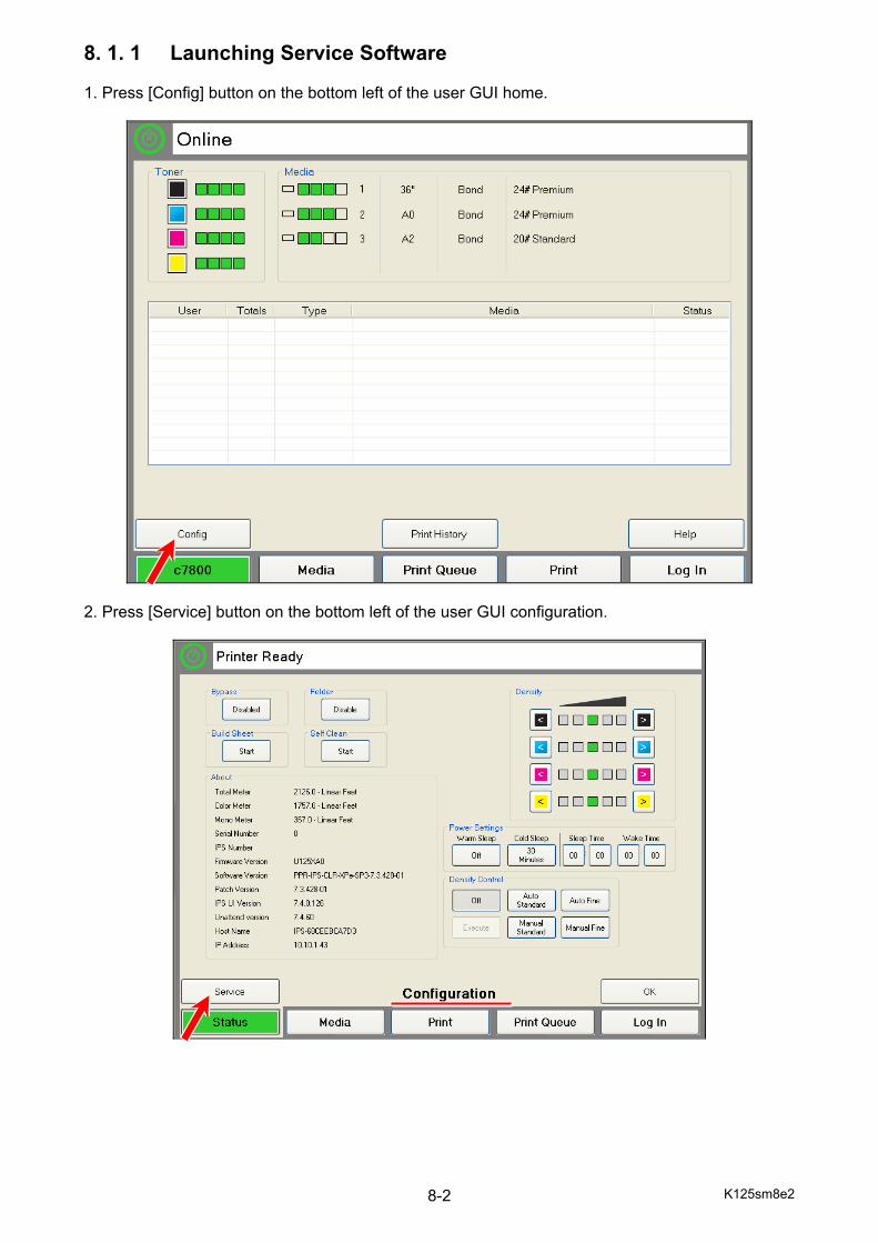
K125sm8e2 8-2
8. 1. 1 Launching Service Software 1. Press [Config] button on the bottom left of the user GUI home.
2. Press [Service] button on the bottom left of the user GUI configuration.
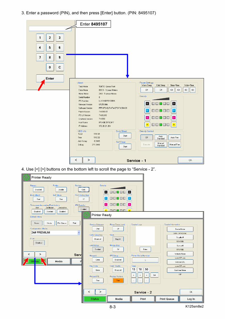
K125sm8e2 8-3
3. Enter a password (PIN), and then press [Enter] button. (PIN: 8495107)
4. Use [<] [>] buttons on the bottom left to scroll the page to “Service - 2”.
Enter 8495107
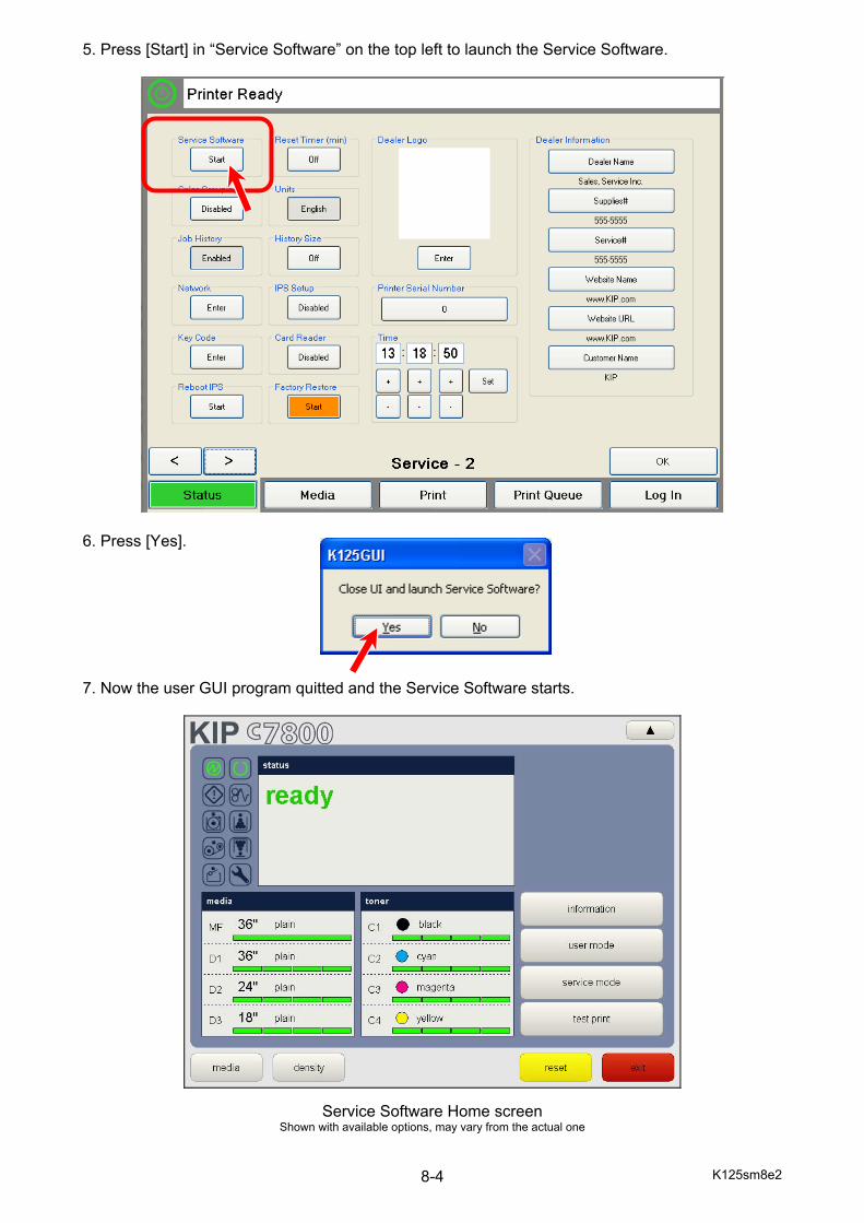
K125sm8e2 8-4
5. Press [Start] in “Service Software” on the top left to launch the Service Software.
6. Press [Yes]. 7. Now the user GUI program quitted and the Service Software starts.
Service Software Home screen Shown with available options, may vary from the actual one
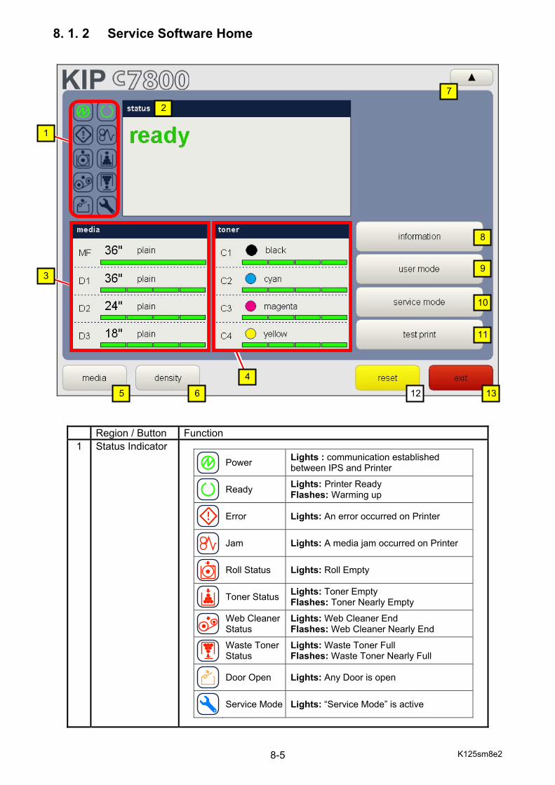
K125sm8e2 8-5
8. 1. 2 Service Software Home
Region / Button Function 1 Status Indicator
Power Lights : communication established
between IPS and Printer
Ready Lights: Printer Ready
Flashes: Warming up
Error Lights: An error occurred on Printer
Jam Lights: A media jam occurred on Printer
Roll Status Lights: Roll Empty
Toner Status Lights: Toner Empty
Flashes: Toner Nearly Empty
Web Cleaner Status
Lights: Web Cleaner End Flashes: Web Cleaner Nearly End
Waste Toner Status
Lights: Waste Toner Full Flashes: Waste Toner Nearly Full
Door Open Lights: Any Door is open
Service Mode Lights: “Service Mode” is active
2
1
3
4
5 6
7
8
9
10
11
12 13
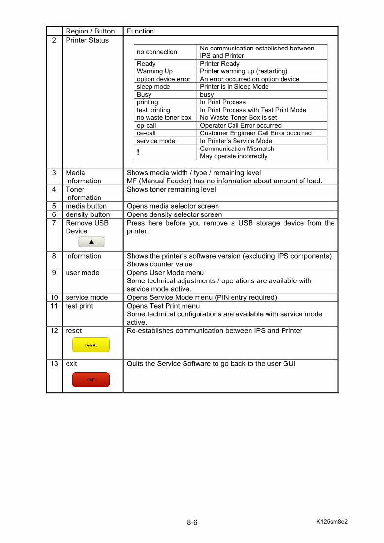
K125sm8e2 8-6
Region / Button Function
2 Printer Status no connection No communication established between
IPS and Printer Ready Printer Ready Warming Up Printer warming up (restarting) option device error An error occurred on option device sleep mode Printer is in Sleep Mode Busy busy printing In Print Process test printing In Print Process with Test Print Mode no waste toner box No Waste Toner Box is set op-call Operator Call Error occurred ce-call Customer Engineer Call Error occurred service mode In Printer’s Service Mode
! Communication Mismatch May operate incorrectly
3 Media
Information Shows media width / type / remaining level MF (Manual Feeder) has no information about amount of load.
4 Toner Information
Shows toner remaining level
5 media button Opens media selector screen 6 density button Opens density selector screen 7 Remove USB
Device
Press here before you remove a USB storage device from the printer.
8 Information Shows the printer’s software version (excluding IPS components) Shows counter value
9 user mode Opens User Mode menu Some technical adjustments / operations are available with service mode active.
10 service mode Opens Service Mode menu (PIN entry required) 11 test print Opens Test Print menu
Some technical configurations are available with service mode active.
12 reset
Re-establishes communication between IPS and Printer
13 exit
Quits the Service Software to go back to the user GUI
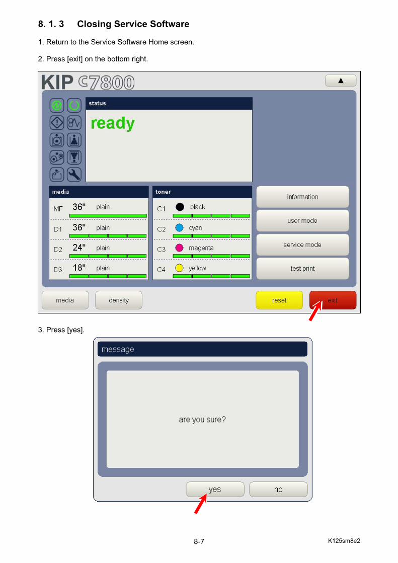
K125sm8e2 8-7
8. 1. 3 Closing Service Software 1. Return to the Service Software Home screen. 2. Press [exit] on the bottom right. 3. Press [yes].
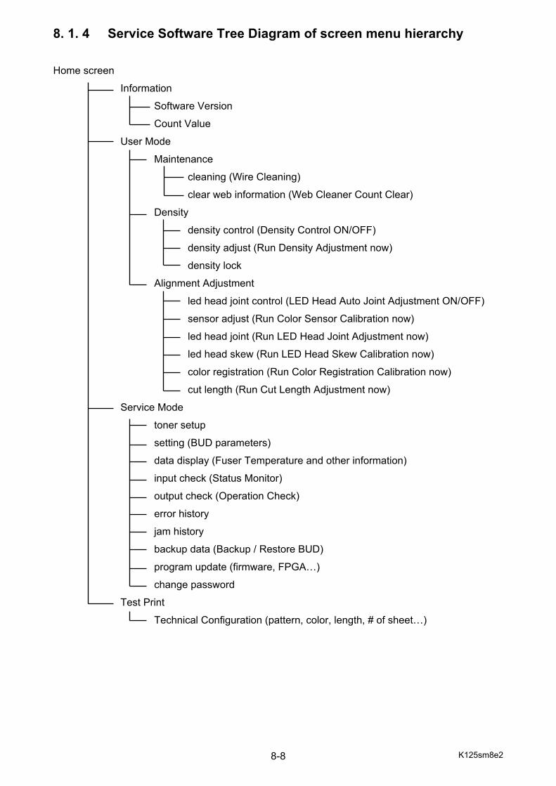
K125sm8e2 8-8
8. 1. 4 Service Software Tree Diagram of screen menu hierarchy Home screen
Information
Software Version
Count Value
User Mode
Maintenance
cleaning (Wire Cleaning)
clear web information (Web Cleaner Count Clear)
Density
density control (Density Control ON/OFF)
density adjust (Run Density Adjustment now)
density lock
Alignment Adjustment
led head joint control (LED Head Auto Joint Adjustment ON/OFF)
sensor adjust (Run Color Sensor Calibration now)
led head joint (Run LED Head Joint Adjustment now)
led head skew (Run LED Head Skew Calibration now)
color registration (Run Color Registration Calibration now)
cut length (Run Cut Length Adjustment now)
Service Mode
toner setup
setting (BUD parameters)
data display (Fuser Temperature and other information)
input check (Status Monitor)
output check (Operation Check)
error history
jam history
backup data (Backup / Restore BUD)
program update (firmware, FPGA…)
change password
Test Print
Technical Configuration (pattern, color, length, # of sheet…)
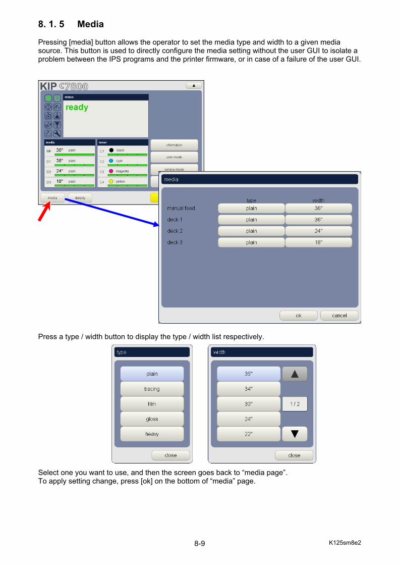
K125sm8e2 8-9
8. 1. 5 Media Pressing [media] button allows the operator to set the media type and width to a given media source. This button is used to directly configure the media setting without the user GUI to isolate a problem between the IPS programs and the printer firmware, or in case of a failure of the user GUI.
Press a type / width button to display the type / width list respectively. Select one you want to use, and then the screen goes back to “media page”. To apply setting change, press [ok] on the bottom of “media” page.

K125sm8e2 8-10
8. 1. 6 Density Pressing [density] button allows the operator to set the master density level.
Tap the arrow button to change the density level.
After the green cursor moves to the destination level, press [ok] on the bottom of “density” page.
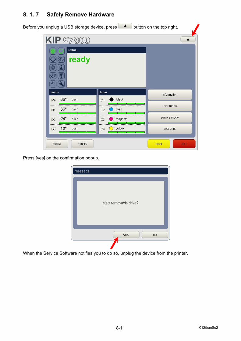
K125sm8e2 8-11
8. 1. 7 Safely Remove Hardware Before you unplug a USB storage device, press button on the top right.
Press [yes] on the confirmation popup.
When the Service Software notifies you to do so, unplug the device from the printer.
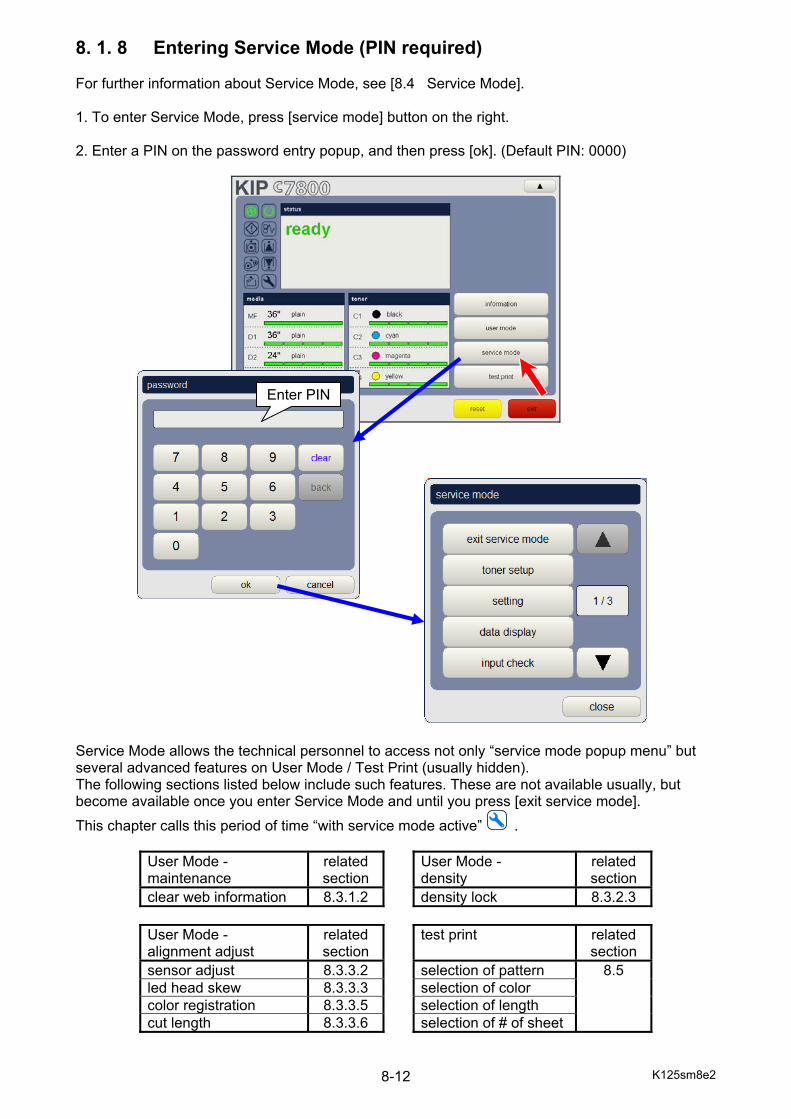
K125sm8e2 8-12
8. 1. 8 Entering Service Mode (PIN required) For further information about Service Mode, see [8.4 Service Mode]. 1. To enter Service Mode, press [service mode] button on the right. 2. Enter a PIN on the password entry popup, and then press [ok]. (Default PIN: 0000)
Service Mode allows the technical personnel to access not only “service mode popup menu” but several advanced features on User Mode / Test Print (usually hidden). The following sections listed below include such features. These are not available usually, but become available once you enter Service Mode and until you press [exit service mode].
This chapter calls this period of time “with service mode active” .
User Mode - maintenance
related section
User Mode - density
related section
clear web information 8.3.1.2 density lock 8.3.2.3
User Mode - alignment adjust
related section
test print related section
sensor adjust 8.3.3.2 selection of pattern 8.5 led head skew 8.3.3.3 selection of color color registration 8.3.3.5 selection of length cut length 8.3.3.6 selection of # of sheet
Enter PIN
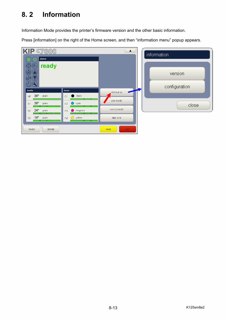
K125sm8e2 8-13
8. 2 Information Information Mode provides the printer’s firmware version and the other basic information. Press [information] on the right of the Home screen, and then “information menu” popup appears.
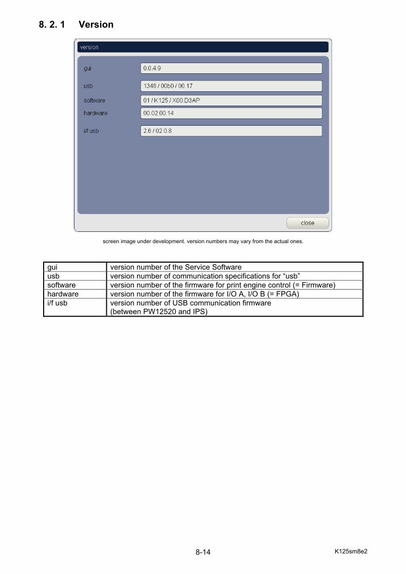
K125sm8e2 8-14
8. 2. 1 Version
screen image under development. version numbers may vary from the actual ones.
gui version number of the Service Software usb version number of communication specifications for “usb” software version number of the firmware for print engine control (= Firmware) hardware version number of the firmware for I/O A, I/O B (= FPGA) i/f usb version number of USB communication firmware
(between PW12520 and IPS)
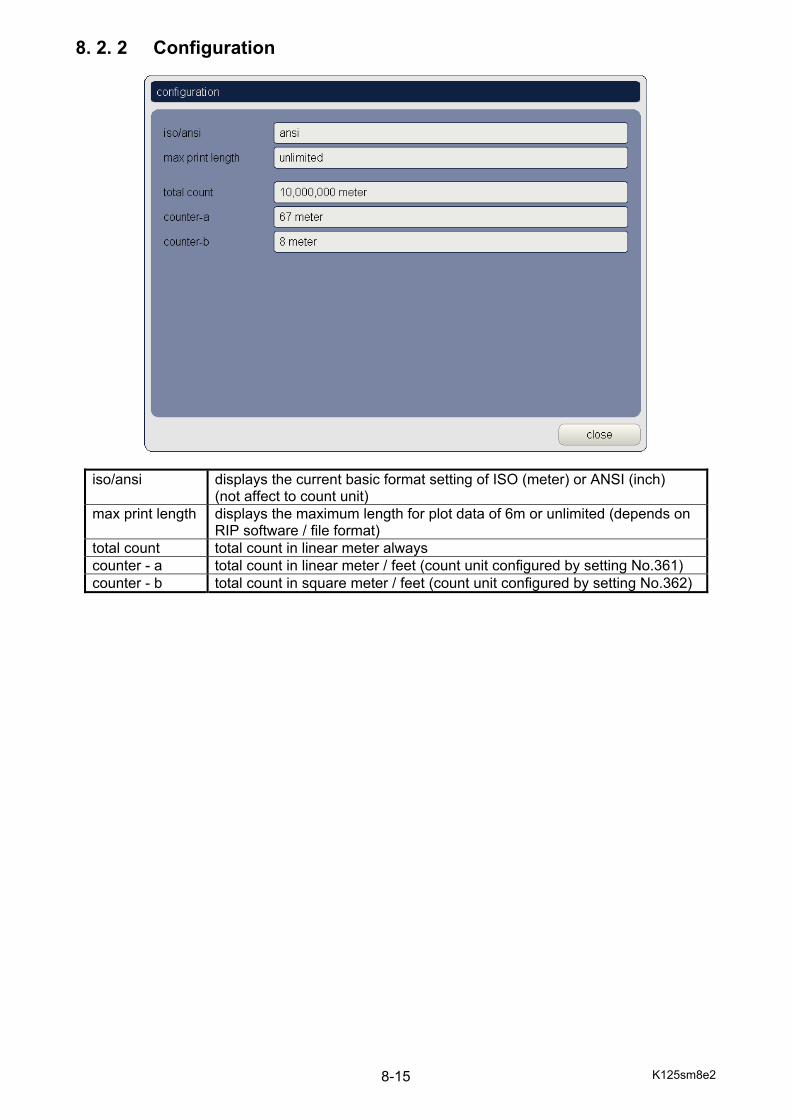
K125sm8e2 8-15
8. 2. 2 Configuration
iso/ansi displays the current basic format setting of ISO (meter) or ANSI (inch) (not affect to count unit)
max print length displays the maximum length for plot data of 6m or unlimited (depends on RIP software / file format)
total count total count in linear meter always counter - a total count in linear meter / feet (count unit configured by setting No.361) counter - b total count in square meter / feet (count unit configured by setting No.362)
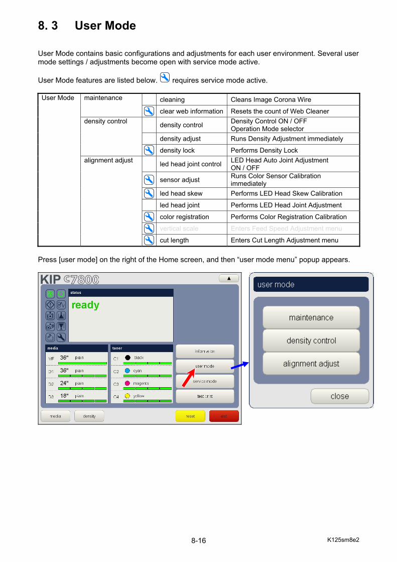
K125sm8e2 8-16
8. 3 User Mode User Mode contains basic configurations and adjustments for each user environment. Several user mode settings / adjustments become open with service mode active.
User Mode features are listed below. requires service mode active. User Mode maintenance cleaning Cleans Image Corona Wire
clear web information Resets the count of Web Cleaner density control density control Density Control ON / OFF
Operation Mode selector density adjust Runs Density Adjustment immediately
density lock Performs Density Lock alignment adjust led head joint control LED Head Auto Joint Adjustment
ON / OFF
sensor adjust Runs Color Sensor Calibration immediately
led head skew Performs LED Head Skew Calibration
led head joint Performs LED Head Joint Adjustment
color registration Performs Color Registration Calibration
vertical scale Enters Feed Speed Adjustment menu
cut length Enters Cut Length Adjustment menu
Press [user mode] on the right of the Home screen, and then “user mode menu” popup appears.
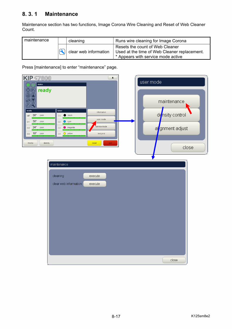
K125sm8e2 8-17
8. 3. 1 Maintenance Maintenance section has two functions, Image Corona Wire Cleaning and Reset of Web Cleaner Count. maintenance cleaning Runs wire cleaning for Image Corona
clear web information Resets the count of Web Cleaner Used at the time of Web Cleaner replacement. * Appears with service mode active
Press [maintenance] to enter “maintenance” page.
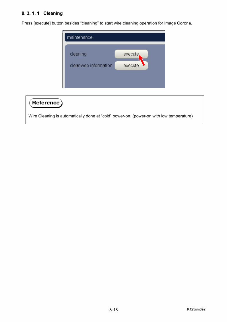
K125sm8e2 8-18
8. 3. 1. 1 Cleaning Press [execute] button besides “cleaning” to start wire cleaning operation for Image Corona.
Reference
Wire Cleaning is automatically done at “cold” power-on. (power-on with low temperature)
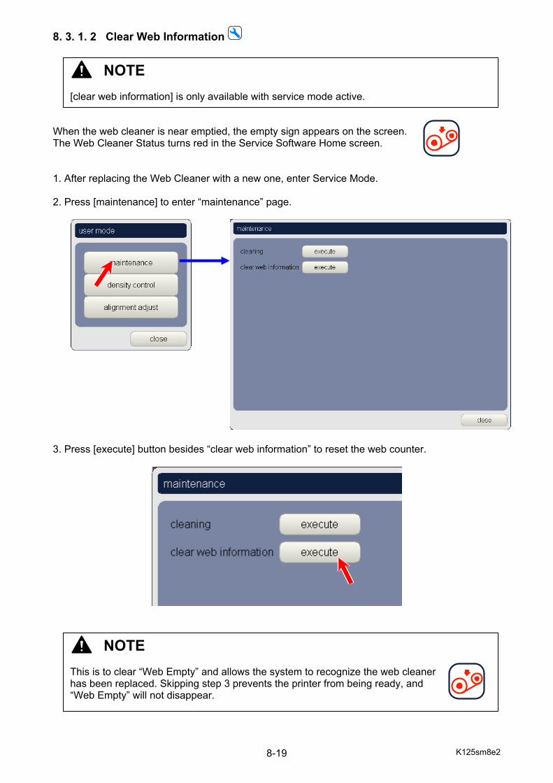
K125sm8e2 8-19
8. 3. 1. 2 Clear Web Information When the web cleaner is near emptied, the empty sign appears on the screen. The Web Cleaner Status turns red in the Service Software Home screen. 1. After replacing the Web Cleaner with a new one, enter Service Mode. 2. Press [maintenance] to enter “maintenance” page. 3. Press [execute] button besides “clear web information” to reset the web counter.
NOTE [clear web information] is only available with service mode active.
NOTE This is to clear “Web Empty” and allows the system to recognize the web cleaner has been replaced. Skipping step 3 prevents the printer from being ready, and “Web Empty” will not disappear.
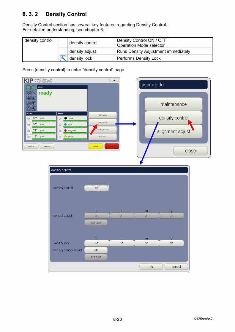
K125sm8e2 8-20
8. 3. 2 Density Control Density Control section has several key features regarding Density Control. For detailed understanding, see chapter 3. density control density control Density Control ON / OFF
Operation Mode selector density adjust Runs Density Adjustment immediately density lock Performs Density Lock
Press [density control] to enter “density control” page.
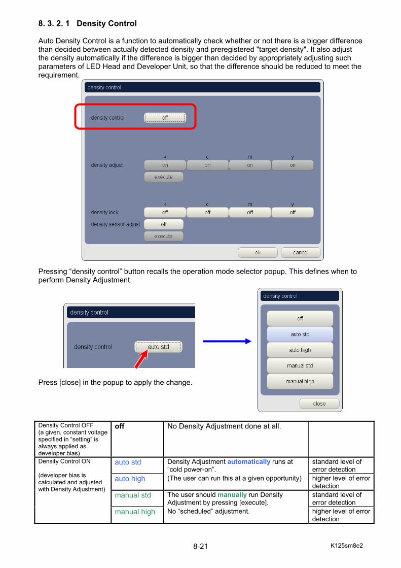
K125sm8e2 8-21
8. 3. 2. 1 Density Control Auto Density Control is a function to automatically check whether or not there is a bigger difference than decided between actually detected density and preregistered "target density". It also adjust the density automatically if the difference is bigger than decided by appropriately adjusting such parameters of LED Head and Developer Unit, so that the difference should be reduced to meet the requirement. Pressing “density control” button recalls the operation mode selector popup. This defines when to perform Density Adjustment. Press [close] in the popup to apply the change. Density Control OFF (a given, constant voltage specified in “setting” is always applied as developer bias)
off No Density Adjustment done at all.
Density Control ON (developer bias is calculated and adjusted with Density Adjustment)
auto std Density Adjustment automatically runs at “cold power-on”.
standard level of error detection
auto high (The user can run this at a given opportunity) higher level of error detection
manual std The user should manually run Density Adjustment by pressing [execute].
standard level of error detection
manual high No “scheduled” adjustment. higher level of error detection
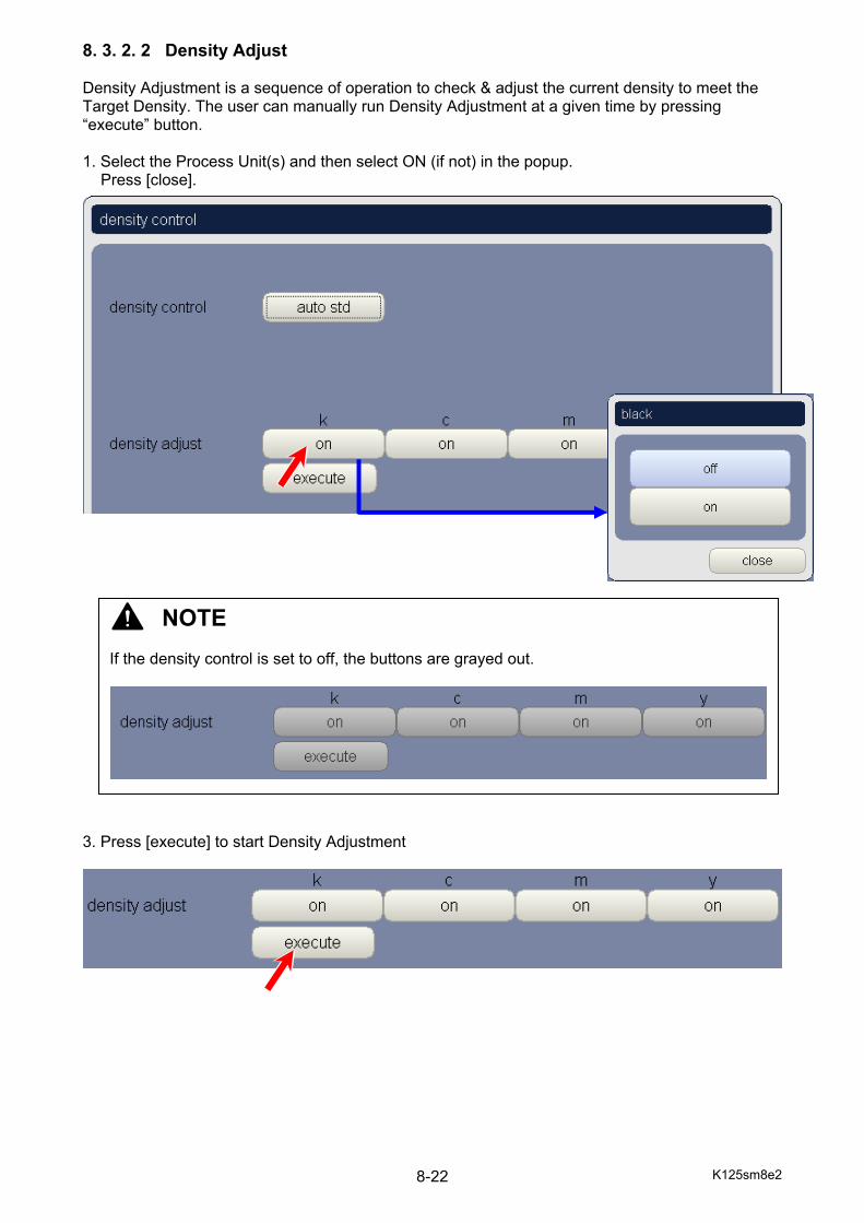
K125sm8e2 8-22
8. 3. 2. 2 Density Adjust Density Adjustment is a sequence of operation to check & adjust the current density to meet the Target Density. The user can manually run Density Adjustment at a given time by pressing “execute” button. 1. Select the Process Unit(s) and then select ON (if not) in the popup.
Press [close]. 3. Press [execute] to start Density Adjustment
NOTE If the density control is set to off, the buttons are grayed out.
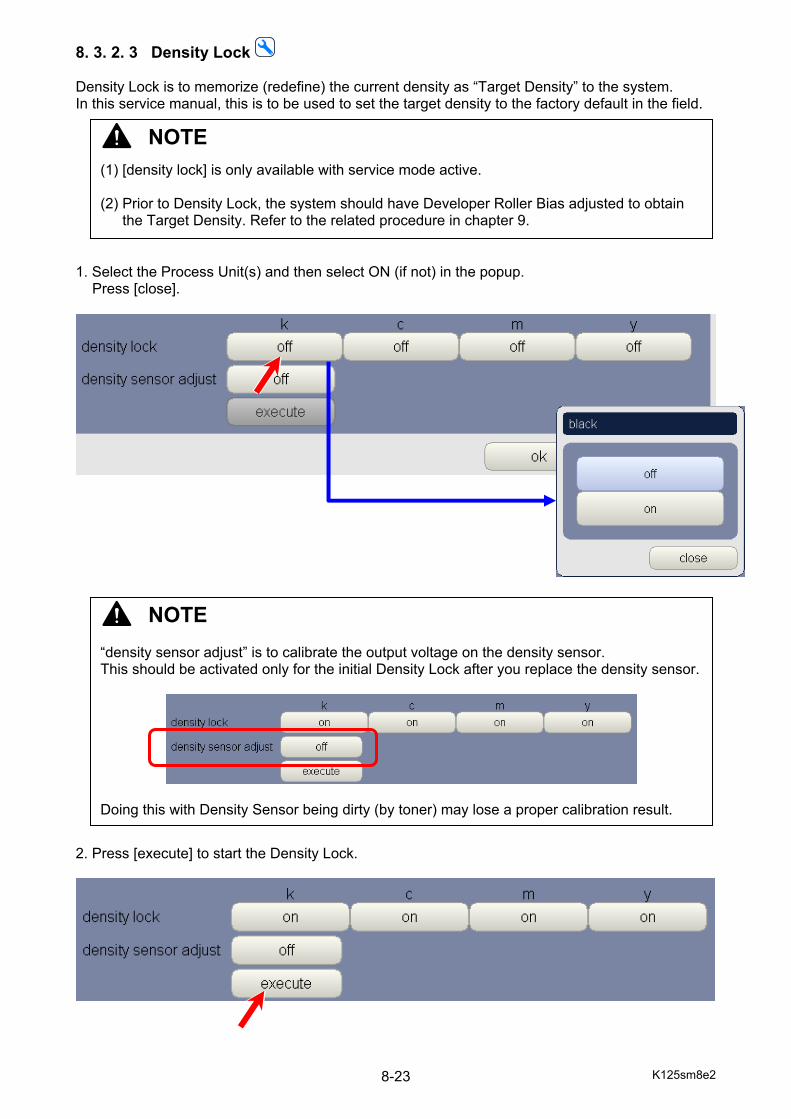
K125sm8e2 8-23
8. 3. 2. 3 Density Lock Density Lock is to memorize (redefine) the current density as “Target Density” to the system. In this service manual, this is to be used to set the target density to the factory default in the field. 1. Select the Process Unit(s) and then select ON (if not) in the popup.
Press [close].
2. Press [execute] to start the Density Lock.
NOTE “density sensor adjust” is to calibrate the output voltage on the density sensor. This should be activated only for the initial Density Lock after you replace the density sensor.
Doing this with Density Sensor being dirty (by toner) may lose a proper calibration result.
NOTE (1) [density lock] is only available with service mode active. (2) Prior to Density Lock, the system should have Developer Roller Bias adjusted to obtain
the Target Density. Refer to the related procedure in chapter 9.
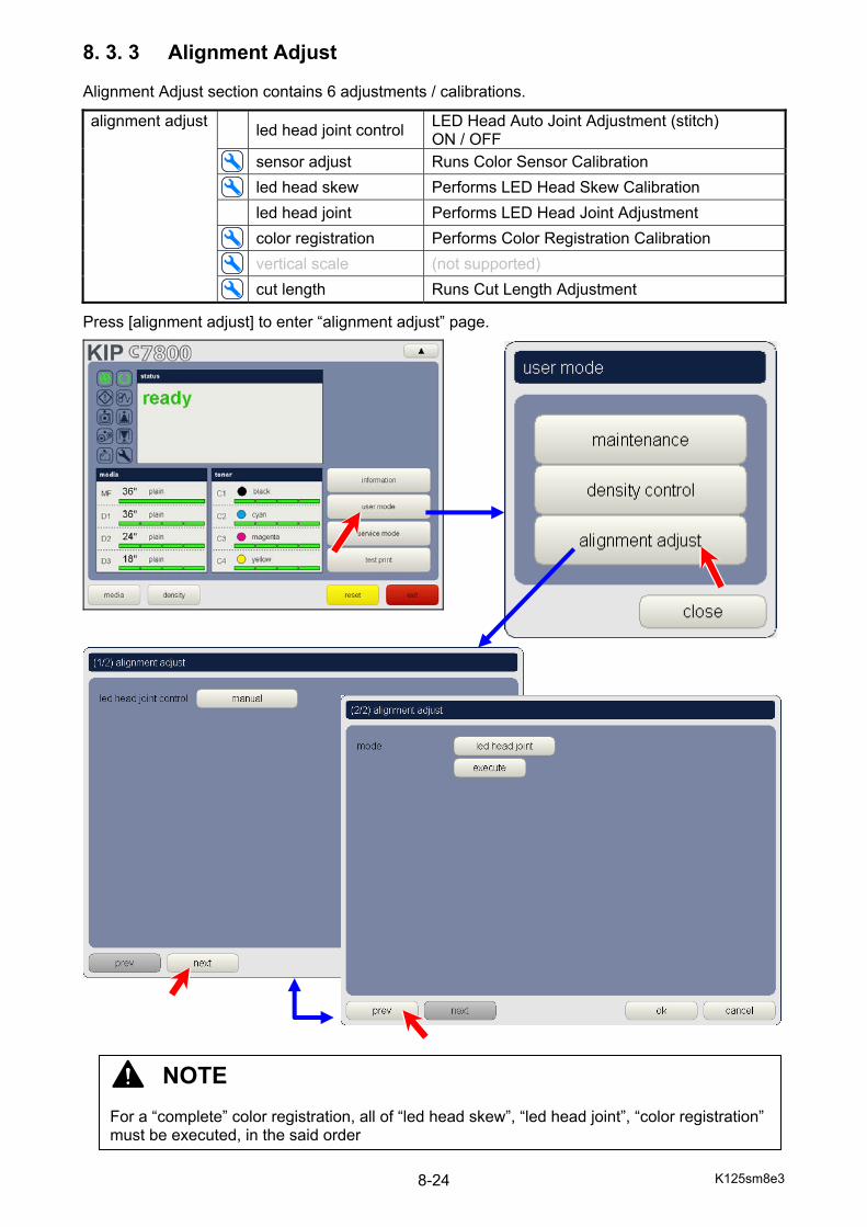
K125sm8e3 8-24
8. 3. 3 Alignment Adjust Alignment Adjust section contains 6 adjustments / calibrations.
alignment adjust led head joint control LED Head Auto Joint Adjustment (stitch) ON / OFF
sensor adjust Runs Color Sensor Calibration led head skew Performs LED Head Skew Calibration led head joint Performs LED Head Joint Adjustment color registration Performs Color Registration Calibration vertical scale (not supported) cut length Runs Cut Length Adjustment
Press [alignment adjust] to enter “alignment adjust” page.
NOTE For a “complete” color registration, all of “led head skew”, “led head joint”, “color registration” must be executed, in the said order
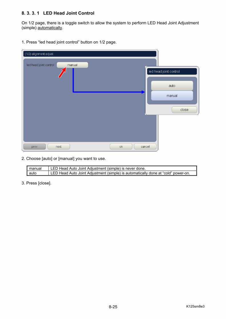
K125sm8e3 8-25
8. 3. 3. 1 LED Head Joint Control On 1/2 page, there is a toggle switch to allow the system to perform LED Head Joint Adjustment (simple) automatically. 1. Press “led head joint control” button on 1/2 page.
2. Choose [auto] or [manual] you want to use.
manual LED Head Auto Joint Adjustment (simple) is never done. auto LED Head Auto Joint Adjustment (simple) is automatically done at “cold” power-on.
3. Press [close].

K125sm8e3 8-26
8. 3. 3. 2 Sensor Adjust “sensor adjust” performs Color Sensor Calibration. If a ce-call error happens during the other operations in “alignment adjust”, first check and clean Color Sensor, and then run Color Sensor Calibration with “sensor adjust”. It takes about 1 minute to complete. No chart, paper, measuring instrument is required. 1. Press [next] on the bottom of 1/2 page.
NOTE [sensor adjust] is only available with service mode active.
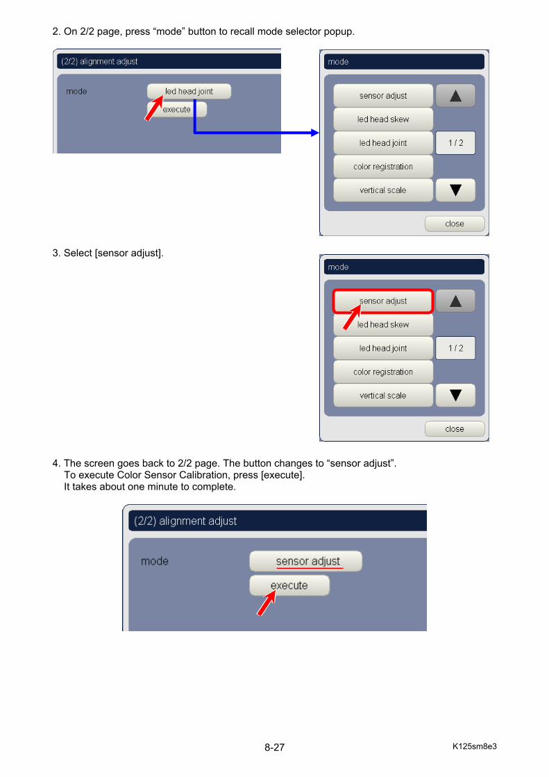
K125sm8e3 8-27
2. On 2/2 page, press “mode” button to recall mode selector popup.
3. Select [sensor adjust]. 4. The screen goes back to 2/2 page. The button changes to “sensor adjust”.
To execute Color Sensor Calibration, press [execute]. It takes about one minute to complete.
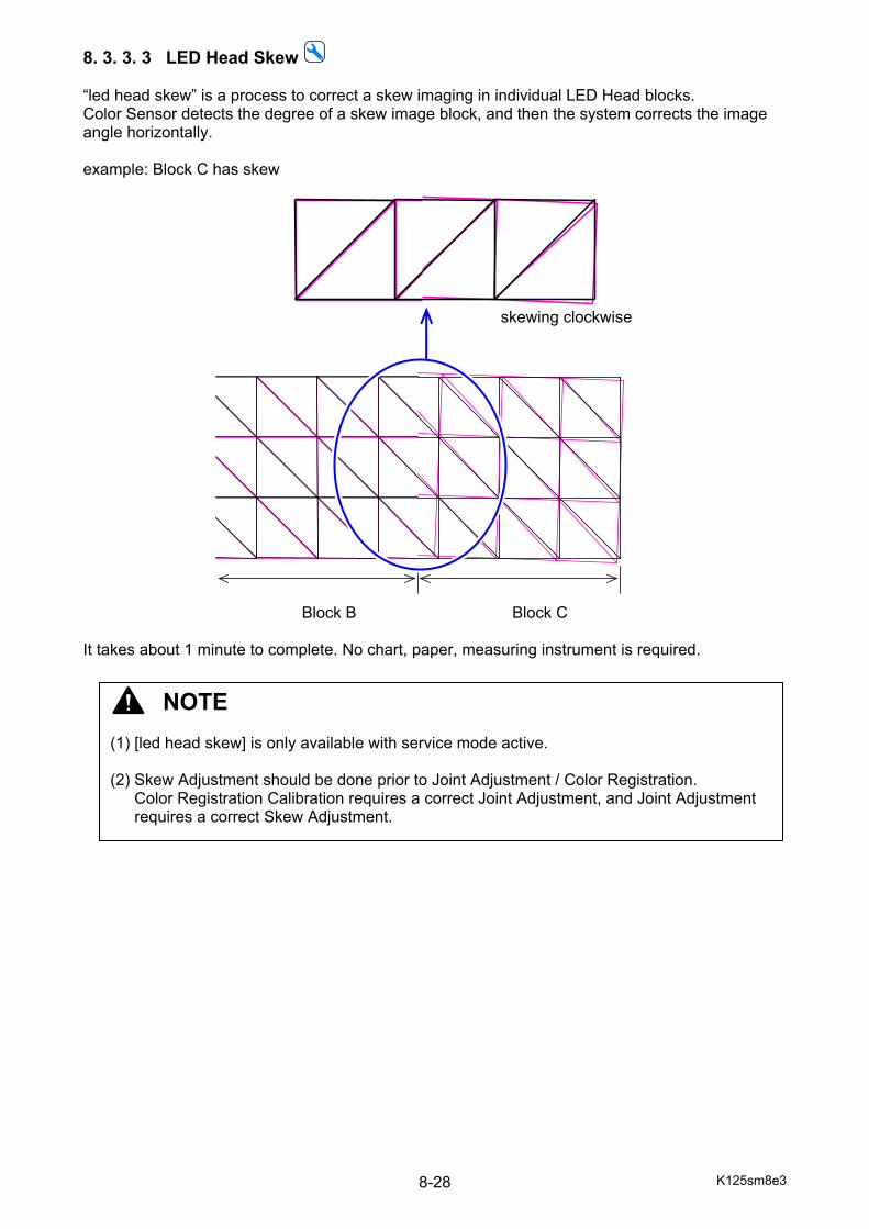
K125sm8e3 8-28
8. 3. 3. 3 LED Head Skew “led head skew” is a process to correct a skew imaging in individual LED Head blocks. Color Sensor detects the degree of a skew image block, and then the system corrects the image angle horizontally. example: Block C has skew
skewing clockwise
Block B Block C It takes about 1 minute to complete. No chart, paper, measuring instrument is required.
NOTE (1) [led head skew] is only available with service mode active. (2) Skew Adjustment should be done prior to Joint Adjustment / Color Registration.
Color Registration Calibration requires a correct Joint Adjustment, and Joint Adjustment requires a correct Skew Adjustment.
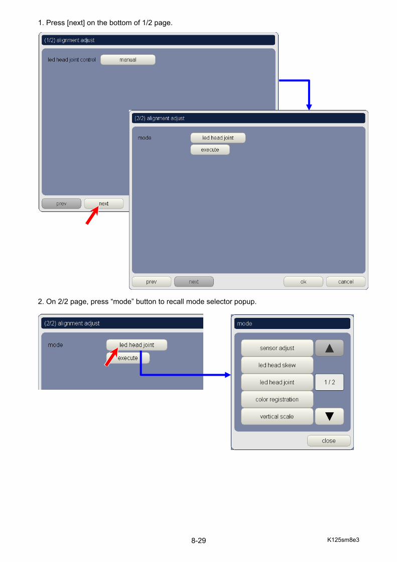
K125sm8e3 8-29
1. Press [next] on the bottom of 1/2 page. 2. On 2/2 page, press “mode” button to recall mode selector popup.

K125sm8e3 8-30
3. Select [led head skew]. 4. The screen goes back to 2/2 page. The button changes to “led head skew”.
To execute LED Head Skew Calibration, press [execute]. It takes about one minute to complete.
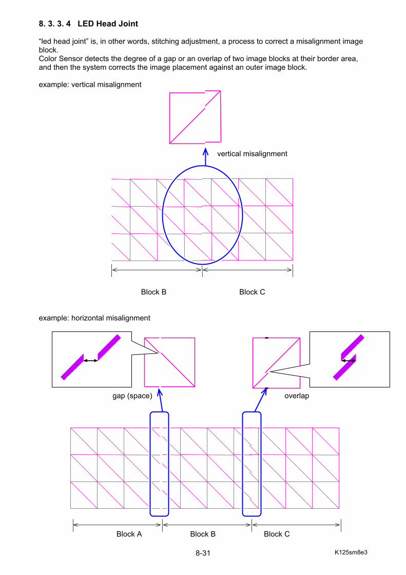
K125sm8e3 8-31
8. 3. 3. 4 LED Head Joint “led head joint” is, in other words, stitching adjustment, a process to correct a misalignment image block. Color Sensor detects the degree of a gap or an overlap of two image blocks at their border area, and then the system corrects the image placement against an outer image block. example: vertical misalignment
vertical misalignment
Block B Block C example: horizontal misalignment
gap (space) overlap
Block A Block B Block C
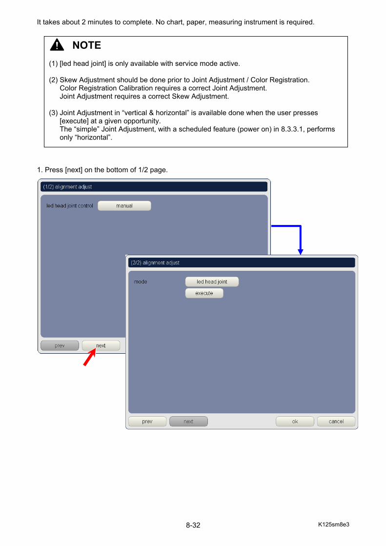
K125sm8e3 8-32
It takes about 2 minutes to complete. No chart, paper, measuring instrument is required. 1. Press [next] on the bottom of 1/2 page.
NOTE (1) [led head joint] is only available with service mode active. (2) Skew Adjustment should be done prior to Joint Adjustment / Color Registration.
Color Registration Calibration requires a correct Joint Adjustment. Joint Adjustment requires a correct Skew Adjustment.
(3) Joint Adjustment in “vertical & horizontal” is available done when the user presses
[execute] at a given opportunity. The “simple” Joint Adjustment, with a scheduled feature (power on) in 8.3.3.1, performs only “horizontal”.

K125sm8e3 8-33
2. On 2/2 page, press “mode” button to recall mode selector popup.
3. Select [led head joint]. 4. The screen goes back to 2/2 page. The button changes to “led head joint”.
To execute LED Head Joint Adjustment, press [execute]. It takes about two minutes to complete.
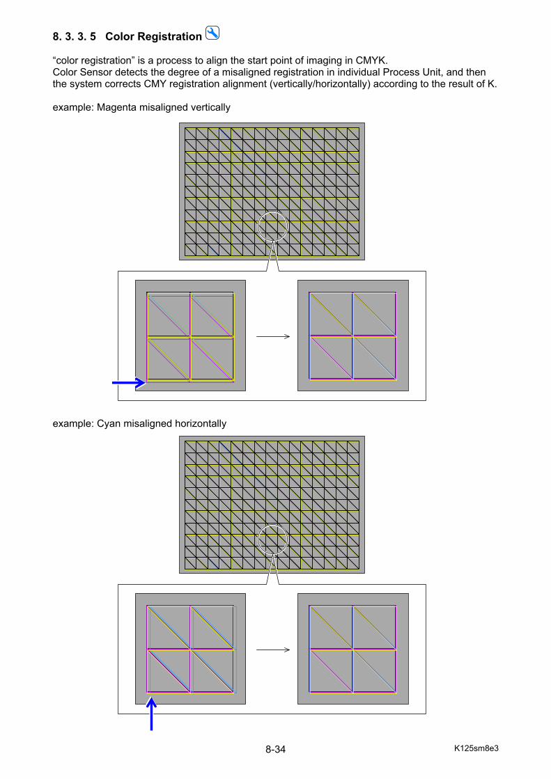
K125sm8e3 8-34
8. 3. 3. 5 Color Registration “color registration” is a process to align the start point of imaging in CMYK. Color Sensor detects the degree of a misaligned registration in individual Process Unit, and then the system corrects CMY registration alignment (vertically/horizontally) according to the result of K. example: Magenta misaligned vertically example: Cyan misaligned horizontally
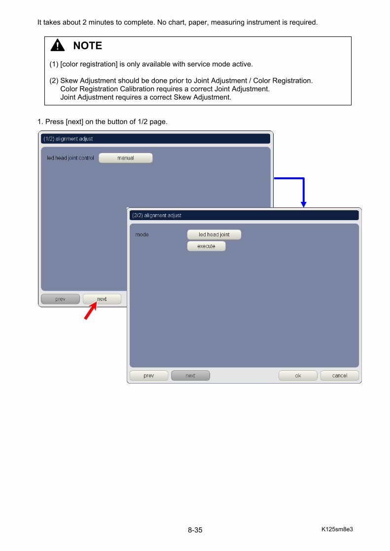
K125sm8e3 8-35
It takes about 2 minutes to complete. No chart, paper, measuring instrument is required. 1. Press [next] on the button of 1/2 page.
NOTE (1) [color registration] is only available with service mode active. (2) Skew Adjustment should be done prior to Joint Adjustment / Color Registration.
Color Registration Calibration requires a correct Joint Adjustment. Joint Adjustment requires a correct Skew Adjustment.
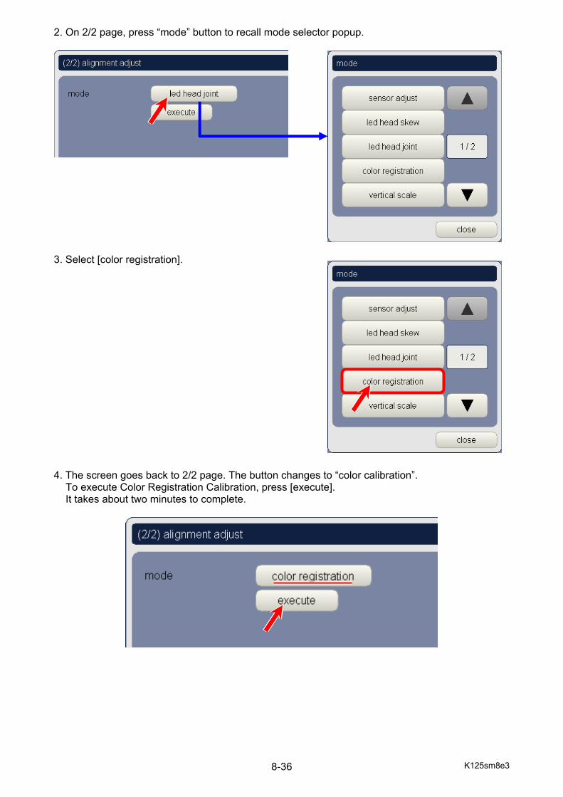
K125sm8e3 8-36
2. On 2/2 page, press “mode” button to recall mode selector popup.
3. Select [color registration]. 4. The screen goes back to 2/2 page. The button changes to “color calibration”.
To execute Color Registration Calibration, press [execute]. It takes about two minutes to complete.

K125sm8e3 8-37
8. 3. 3. 6 Vertical Scale
8. 3. 3. 7 Cut Length “cut length” is an automatic process to compensate the cut length and the leading registration at a time. In this process, the system automatically starts sample printing (5 sheets in 8.5 inch long and then another 5 in 48 inch) with a selected Roll Deck. Color Sensor detects the sheets’ feed distance, and then the system adjusts the Cutter operation timing to get 8.5 or 48 inch long sheet. It takes about 5 minutes for cut length adjustment against “all” decks to complete. For one deck only, it takes about 2 minutes. A plain paper / bond roll media (remaining 8 meters or longer, the width does not matter) should be loaded to a Roll Deck you want to have cut length adjustment. (Each Roll Deck has a parameter of “cutter timing”) Furthermore, during cut length adjustment, the system performs leading registration adjustment at the same time. When cult length adjustment is done against one Roll Deck, leading registration will be also adjusted to the Roll Deck, and the result will be applied to the other Roll Deck. (All Roll Decks uses a common parameter of “leading registration”) 1. Load a roll media in the Roll Deck to be adjusted.
NOTE [cut length] is only available with service mode active.
NOTE This mode is only for factory use. Please do not operate this in the field as it may negatively affect the Color Registration quality.
NOTE This mode is only for factory use. Please do not operate this in the field as it may negatively affect the Color Registration quality.
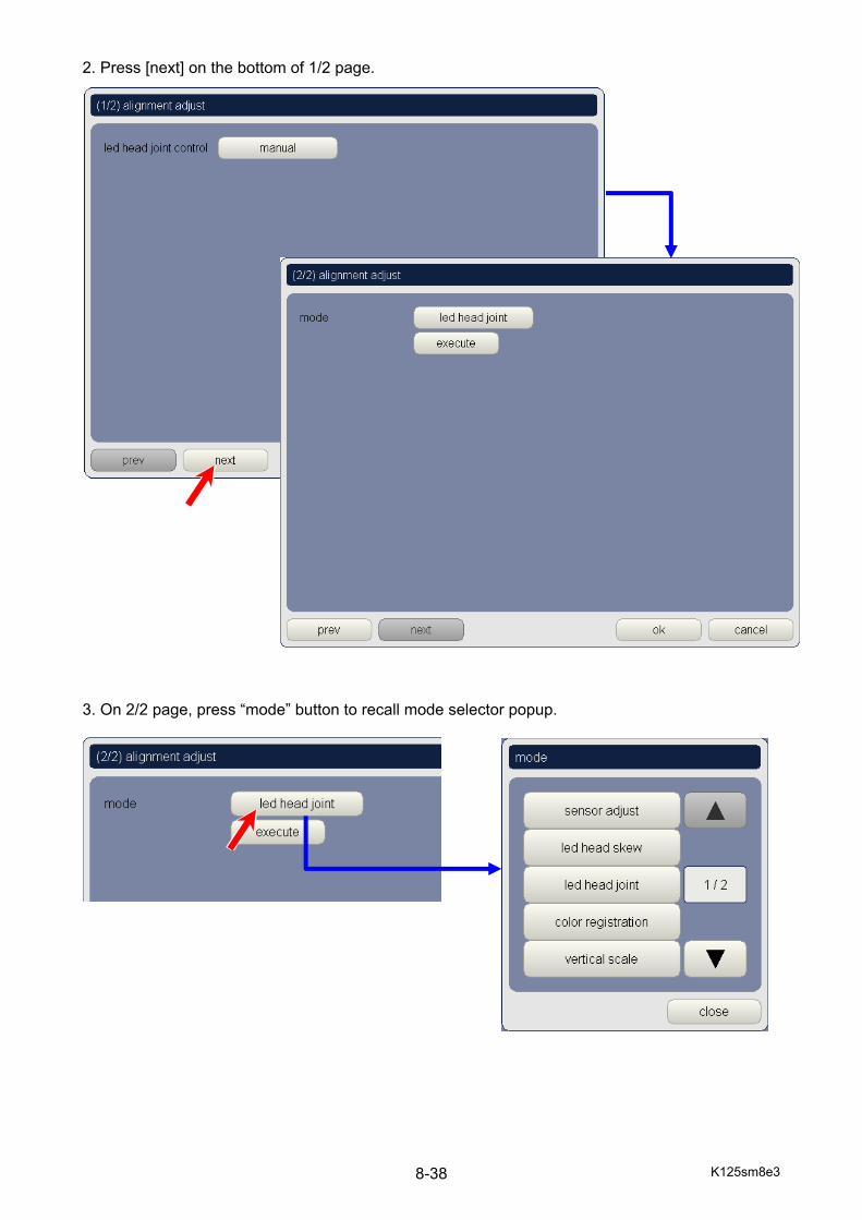
K125sm8e3 8-38
2. Press [next] on the bottom of 1/2 page. 3. On 2/2 page, press “mode” button to recall mode selector popup.
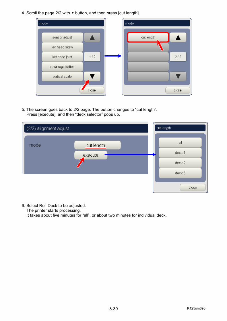
K125sm8e3 8-39
4. Scroll the page 2/2 with button, and then press [cut length]. 5. The screen goes back to 2/2 page. The button changes to “cut length”.
Press [execute], and then “deck selector” pops up.
6. Select Roll Deck to be adjusted.
The printer starts processing. It takes about five minutes for “all”, or about two minutes for individual deck.
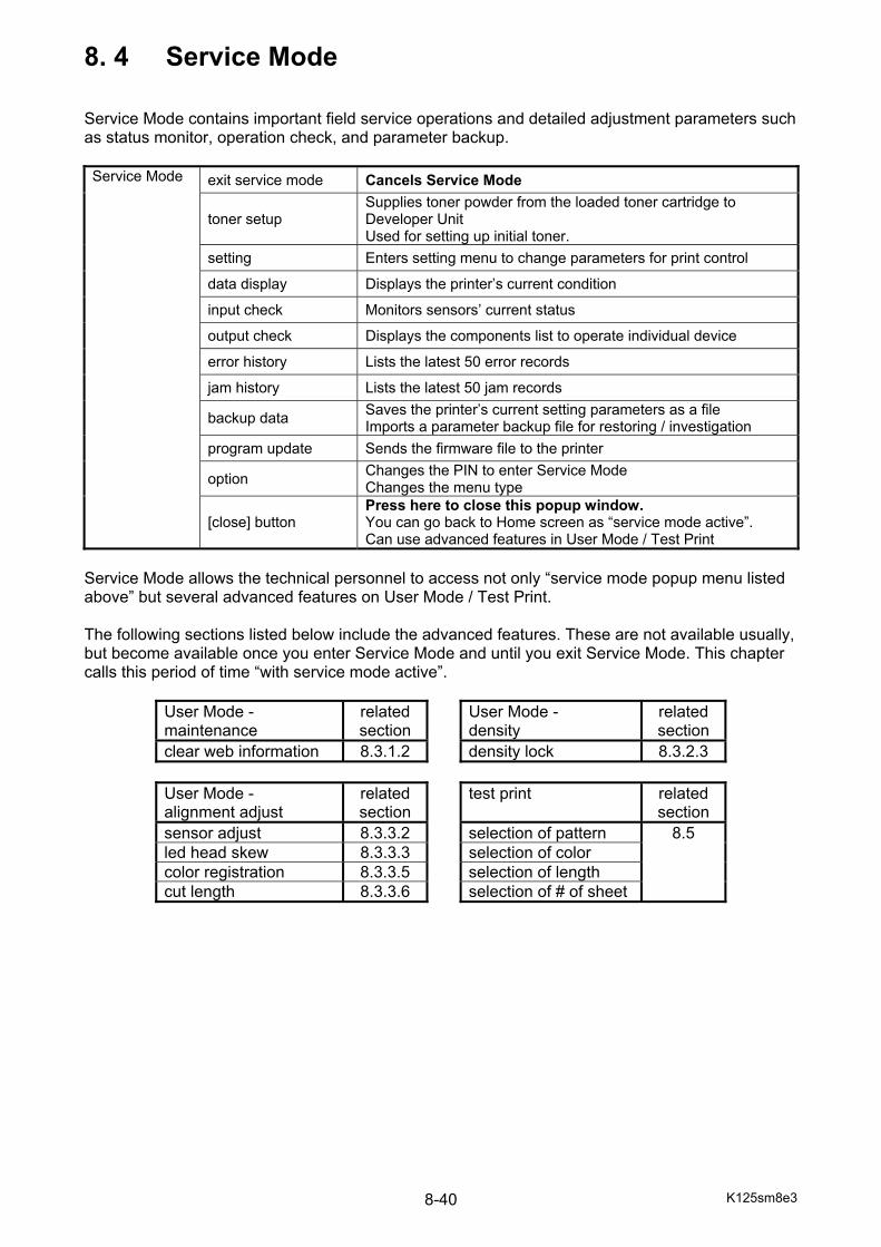
K125sm8e3 8-40
8. 4 Service Mode Service Mode contains important field service operations and detailed adjustment parameters such as status monitor, operation check, and parameter backup. Service Mode exit service mode Cancels Service Mode
toner setup Supplies toner powder from the loaded toner cartridge to Developer Unit Used for setting up initial toner.
setting Enters setting menu to change parameters for print control data display Displays the printer’s current condition input check Monitors sensors’ current status output check Displays the components list to operate individual device error history Lists the latest 50 error records jam history Lists the latest 50 jam records backup data Saves the printer’s current setting parameters as a file
Imports a parameter backup file for restoring / investigation program update Sends the firmware file to the printer option Changes the PIN to enter Service Mode
Changes the menu type
[close] button Press here to close this popup window. You can go back to Home screen as “service mode active”. Can use advanced features in User Mode / Test Print
Service Mode allows the technical personnel to access not only “service mode popup menu listed above” but several advanced features on User Mode / Test Print. The following sections listed below include the advanced features. These are not available usually, but become available once you enter Service Mode and until you exit Service Mode. This chapter calls this period of time “with service mode active”.
User Mode - maintenance
related section
User Mode - density
related section
clear web information 8.3.1.2 density lock 8.3.2.3
User Mode - alignment adjust
related section
test print related section
sensor adjust 8.3.3.2 selection of pattern 8.5 led head skew 8.3.3.3 selection of color color registration 8.3.3.5 selection of length cut length 8.3.3.6 selection of # of sheet
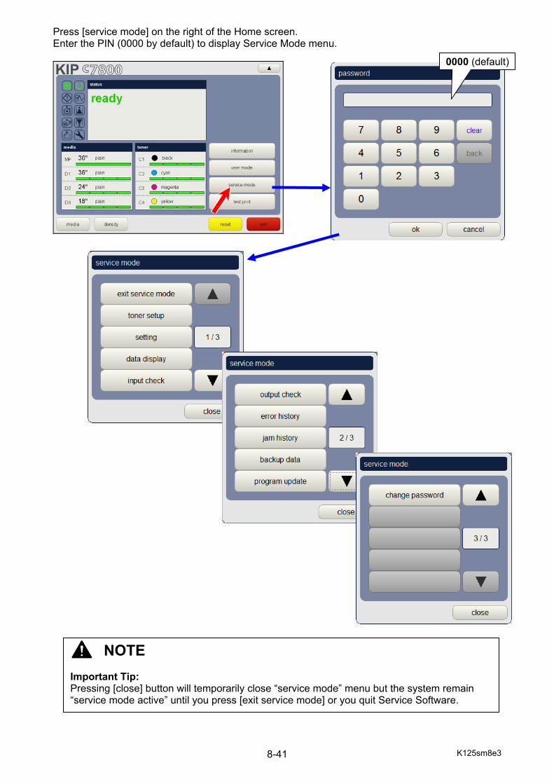
K125sm8e3 8-41
Press [service mode] on the right of the Home screen. Enter the PIN (0000 by default) to display Service Mode menu.
0000 (default)
NOTE Important Tip: Pressing [close] button will temporarily close “service mode” menu but the system remain “service mode active” until you press [exit service mode] or you quit Service Software.
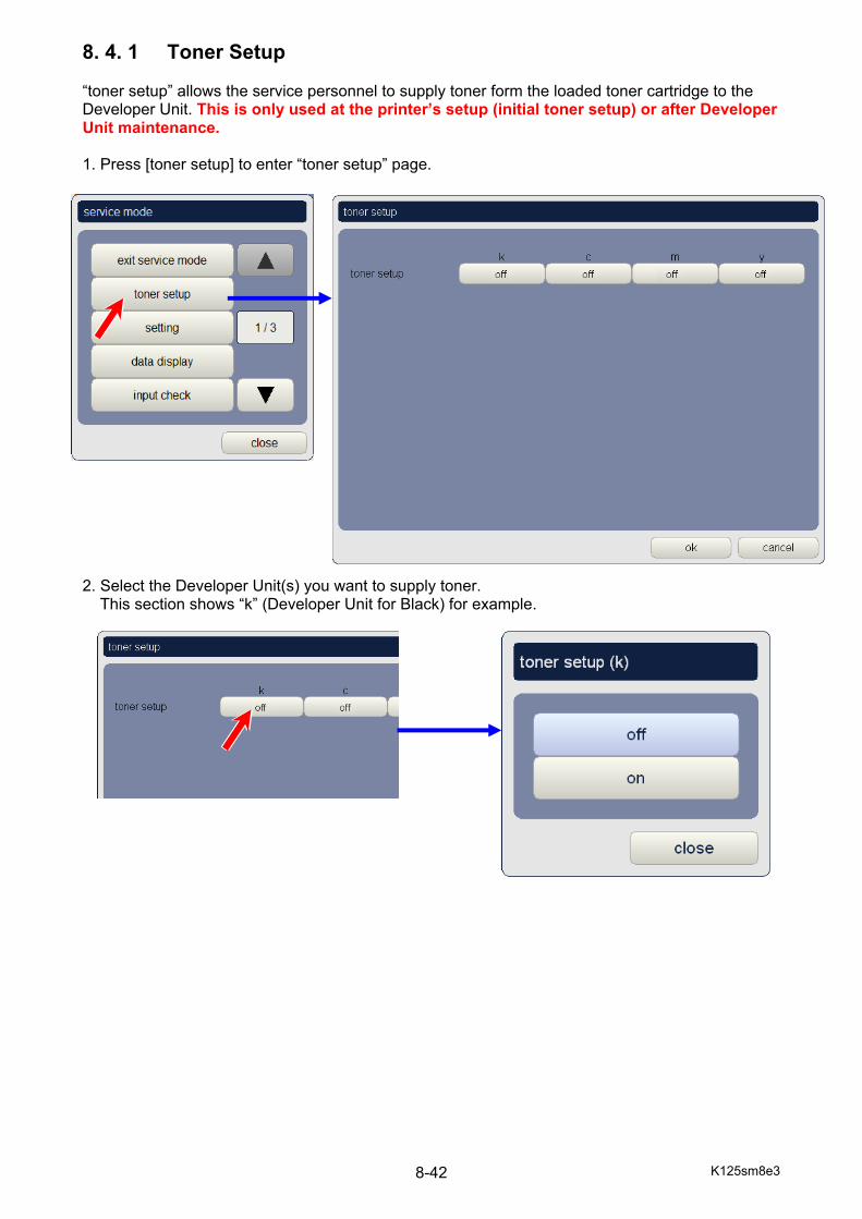
K125sm8e3 8-42
8. 4. 1 Toner Setup “toner setup” allows the service personnel to supply toner form the loaded toner cartridge to the Developer Unit. This is only used at the printer’s setup (initial toner setup) or after Developer Unit maintenance. 1. Press [toner setup] to enter “toner setup” page. 2. Select the Developer Unit(s) you want to supply toner.
This section shows “k” (Developer Unit for Black) for example.

K125sm8e3 8-43
3. Set “toner setup” to ON. 4. Press [close]. Toner Setup is now reserved. 5. Press [ok] on the bottom right to start toner supply on reserved Developer Unit(s). It takes about 10 minutes to complete.
K125sm8e3 8-44
8. 4. 2 Setting “setting” handles the printer’s parameters. “setting menu” separates many items in “setting” into several categories of counter, fuser, high voltage, image enhance, image/print position, motor, print density, print function. * Setting items and their setting values may be called “BUD (BackUpData)” in some sections. 8. 4. 2. 1 How to change setting parameter 1. Press [setting] to enter “setting menu”. In the “setting menu”, you can find a setting item by [all] (the entire numerical listing) or a category (filtered, listed only related items by the category name).
NOTE It is highly recommended to backup the current parameters prior to setting change. For backup procedure, see [8.4.8.1 How to create printer setting].
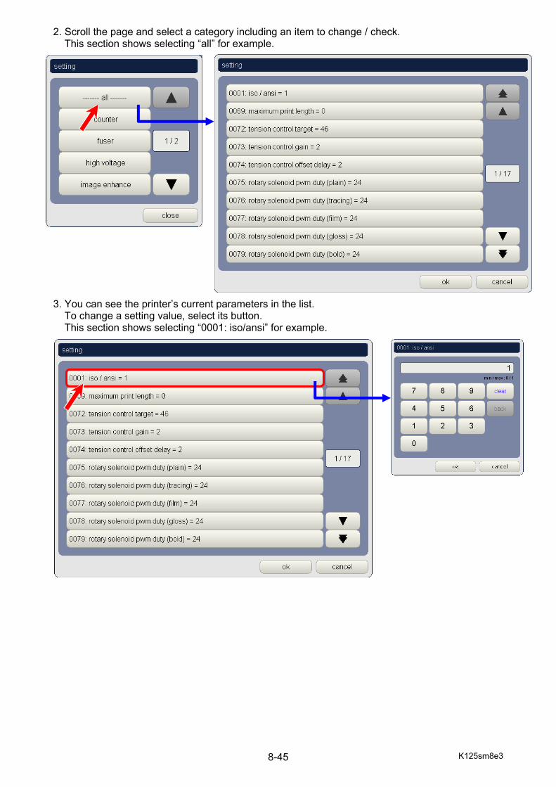
K125sm8e3 8-45
2. Scroll the page and select a category including an item to change / check. This section shows selecting “all” for example.
3. You can see the printer’s current parameters in the list.
To change a setting value, select its button. This section shows selecting “0001: iso/ansi” for example.
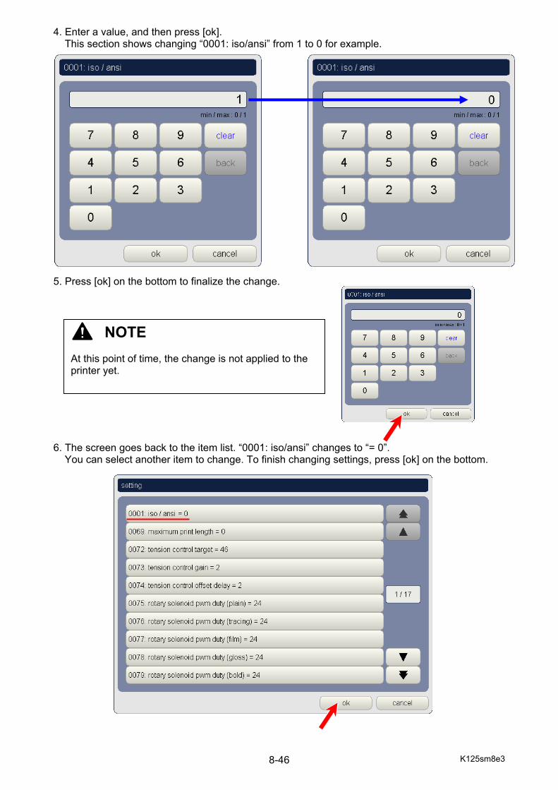
K125sm8e3 8-46
4. Enter a value, and then press [ok]. This section shows changing “0001: iso/ansi” from 1 to 0 for example.
5. Press [ok] on the bottom to finalize the change.
6. The screen goes back to the item list. “0001: iso/ansi” changes to “= 0”.
You can select another item to change. To finish changing settings, press [ok] on the bottom.
NOTE At this point of time, the change is not applied to the printer yet.
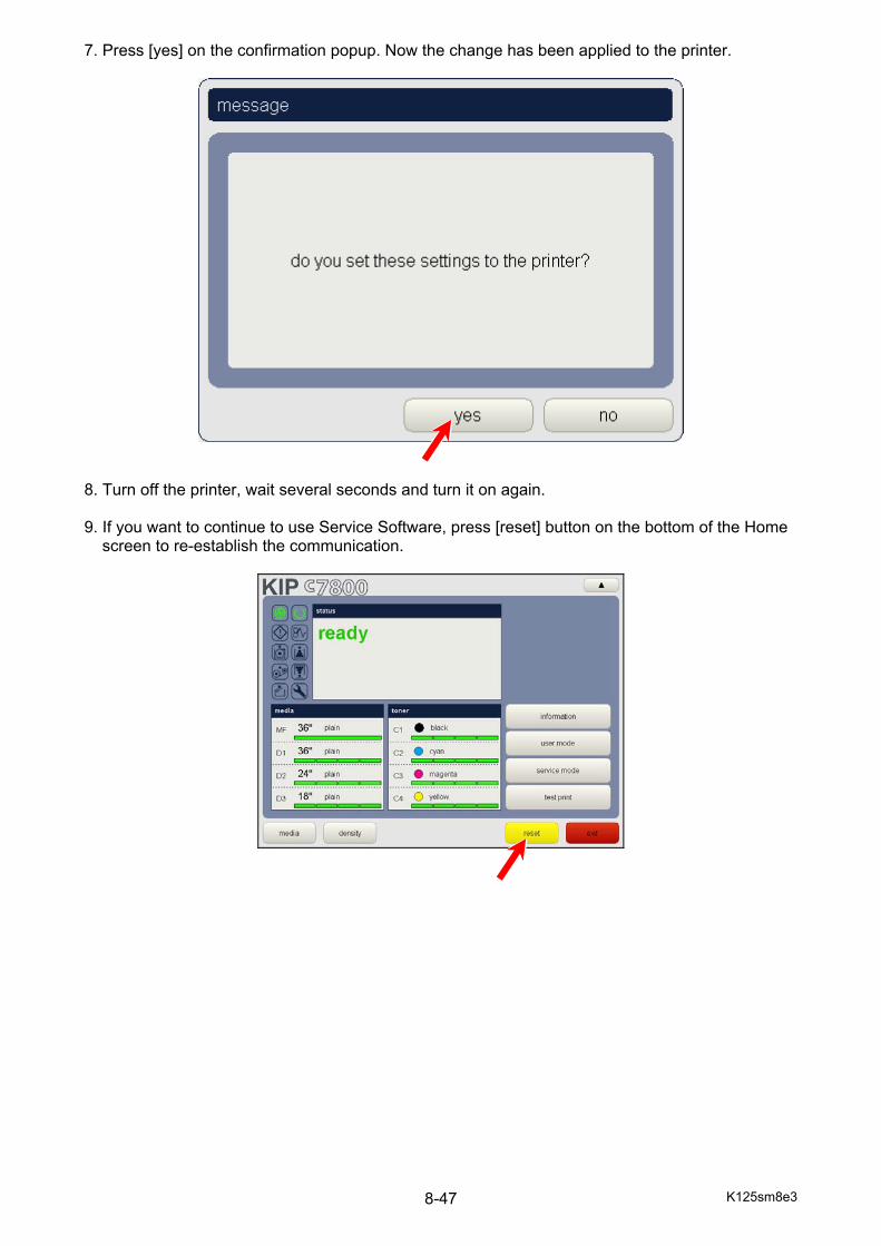
K125sm8e3 8-47
7. Press [yes] on the confirmation popup. Now the change has been applied to the printer.
8. Turn off the printer, wait several seconds and turn it on again. 9. If you want to continue to use Service Software, press [reset] button on the bottom of the Home
screen to re-establish the communication.
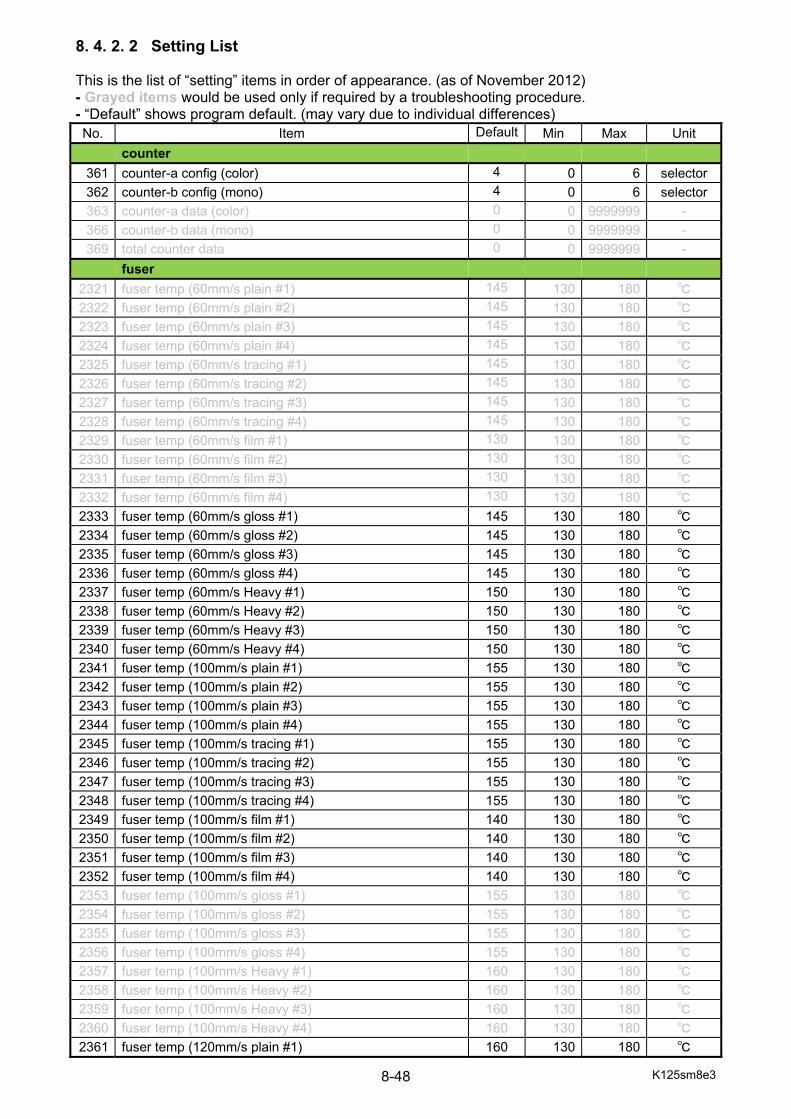
K125sm8e3 8-48
8. 4. 2. 2 Setting List This is the list of “setting” items in order of appearance. (as of November 2012) - Grayed items would be used only if required by a troubleshooting procedure. - “Default” shows program default. (may vary due to individual differences) No. Item Default Min Max Unit
counter 361 counter-a config (color) 4 0 6 selector 362 counter-b config (mono) 4 0 6 selector 363 counter-a data (color) 0 0 9999999 - 366 counter-b data (mono) 0 0 9999999 - 369 total counter data 0 0 9999999 -
fuser 2321 fuser temp (60mm/s plain #1) 145 130 180 ℃ 2322 fuser temp (60mm/s plain #2) 145 130 180 ℃ 2323 fuser temp (60mm/s plain #3) 145 130 180 ℃ 2324 fuser temp (60mm/s plain #4) 145 130 180 ℃ 2325 fuser temp (60mm/s tracing #1) 145 130 180 ℃ 2326 fuser temp (60mm/s tracing #2) 145 130 180 ℃ 2327 fuser temp (60mm/s tracing #3) 145 130 180 ℃ 2328 fuser temp (60mm/s tracing #4) 145 130 180 ℃ 2329 fuser temp (60mm/s film #1) 130 130 180 ℃ 2330 fuser temp (60mm/s film #2) 130 130 180 ℃ 2331 fuser temp (60mm/s film #3) 130 130 180 ℃ 2332 fuser temp (60mm/s film #4) 130 130 180 ℃ 2333 fuser temp (60mm/s gloss #1) 145 130 180 ℃ 2334 fuser temp (60mm/s gloss #2) 145 130 180 ℃ 2335 fuser temp (60mm/s gloss #3) 145 130 180 ℃ 2336 fuser temp (60mm/s gloss #4) 145 130 180 ℃ 2337 fuser temp (60mm/s Heavy #1) 150 130 180 ℃ 2338 fuser temp (60mm/s Heavy #2) 150 130 180 ℃ 2339 fuser temp (60mm/s Heavy #3) 150 130 180 ℃ 2340 fuser temp (60mm/s Heavy #4) 150 130 180 ℃ 2341 fuser temp (100mm/s plain #1) 155 130 180 ℃ 2342 fuser temp (100mm/s plain #2) 155 130 180 ℃ 2343 fuser temp (100mm/s plain #3) 155 130 180 ℃ 2344 fuser temp (100mm/s plain #4) 155 130 180 ℃ 2345 fuser temp (100mm/s tracing #1) 155 130 180 ℃ 2346 fuser temp (100mm/s tracing #2) 155 130 180 ℃ 2347 fuser temp (100mm/s tracing #3) 155 130 180 ℃ 2348 fuser temp (100mm/s tracing #4) 155 130 180 ℃ 2349 fuser temp (100mm/s film #1) 140 130 180 ℃ 2350 fuser temp (100mm/s film #2) 140 130 180 ℃ 2351 fuser temp (100mm/s film #3) 140 130 180 ℃ 2352 fuser temp (100mm/s film #4) 140 130 180 ℃ 2353 fuser temp (100mm/s gloss #1) 155 130 180 ℃ 2354 fuser temp (100mm/s gloss #2) 155 130 180 ℃ 2355 fuser temp (100mm/s gloss #3) 155 130 180 ℃ 2356 fuser temp (100mm/s gloss #4) 155 130 180 ℃ 2357 fuser temp (100mm/s Heavy #1) 160 130 180 ℃ 2358 fuser temp (100mm/s Heavy #2) 160 130 180 ℃ 2359 fuser temp (100mm/s Heavy #3) 160 130 180 ℃ 2360 fuser temp (100mm/s Heavy #4) 160 130 180 ℃ 2361 fuser temp (120mm/s plain #1) 160 130 180 ℃
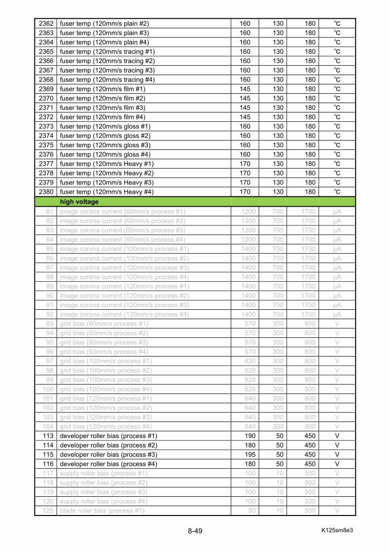
K125sm8e3 8-49
2362 fuser temp (120mm/s plain #2) 160 130 180 ℃ 2363 fuser temp (120mm/s plain #3) 160 130 180 ℃ 2364 fuser temp (120mm/s plain #4) 160 130 180 ℃ 2365 fuser temp (120mm/s tracing #1) 160 130 180 ℃ 2366 fuser temp (120mm/s tracing #2) 160 130 180 ℃ 2367 fuser temp (120mm/s tracing #3) 160 130 180 ℃ 2368 fuser temp (120mm/s tracing #4) 160 130 180 ℃ 2369 fuser temp (120mm/s film #1) 145 130 180 ℃ 2370 fuser temp (120mm/s film #2) 145 130 180 ℃ 2371 fuser temp (120mm/s film #3) 145 130 180 ℃ 2372 fuser temp (120mm/s film #4) 145 130 180 ℃ 2373 fuser temp (120mm/s gloss #1) 160 130 180 ℃ 2374 fuser temp (120mm/s gloss #2) 160 130 180 ℃ 2375 fuser temp (120mm/s gloss #3) 160 130 180 ℃ 2376 fuser temp (120mm/s gloss #4) 160 130 180 ℃ 2377 fuser temp (120mm/s Heavy #1) 170 130 180 ℃ 2378 fuser temp (120mm/s Heavy #2) 170 130 180 ℃ 2379 fuser temp (120mm/s Heavy #3) 170 130 180 ℃ 2380 fuser temp (120mm/s Heavy #4) 170 130 180 ℃
high voltage 81 image corona current (60mm/s process #1) 1200 700 1700 μA 82 image corona current (60mm/s process #2) 1200 700 1700 μA 83 image corona current (60mm/s process #3) 1200 700 1700 μA 84 image corona current (60mm/s process #4) 1200 700 1700 μA 85 image corona current (100mm/s process #1) 1400 700 1700 μA 86 image corona current (100mm/s process #2) 1400 700 1700 μA 87 image corona current (100mm/s process #3) 1400 700 1700 μA 88 image corona current (100mm/s process #4) 1400 700 1700 μA 89 image corona current (120mm/s process #1) 1400 700 1700 μA 90 image corona current (120mm/s process #2) 1400 700 1700 μA 91 image corona current (120mm/s process #3) 1400 700 1700 μA 92 image corona current (120mm/s process #4) 1400 700 1700 μA 93 grid bias (60mm/s process #1) 570 300 800 V 94 grid bias (60mm/s process #2) 570 300 800 V 95 grid bias (60mm/s process #3) 570 300 800 V 96 grid bias (60mm/s process #4) 570 300 800 V 97 grid bias (100mm/s process #1) 620 300 800 V 98 grid bias (100mm/s process #2) 620 300 800 V 99 grid bias (100mm/s process #3) 620 300 800 V
100 grid bias (100mm/s process #4) 620 300 800 V 101 grid bias (120mm/s process #1) 640 300 800 V 102 grid bias (120mm/s process #2) 640 300 800 V 103 grid bias (120mm/s process #3) 640 300 800 V 104 grid bias (120mm/s process #4) 640 300 800 V 113 developer roller bias (process #1) 190 50 450 V 114 developer roller bias (process #2) 180 50 450 V 115 developer roller bias (process #3) 195 50 450 V 116 developer roller bias (process #4) 180 50 450 V 117 supply roller bias (process #1) 100 10 500 V 118 supply roller bias (process #2) 100 10 500 V 119 supply roller bias (process #3) 100 10 500 V 120 supply roller bias (process #4) 100 10 500 V 125 blade roller bias (process #1) 50 10 500 V

K125sm8e3 8-50
126 blade roller bias (process #2) 50 10 500 V 127 blade roller bias (process #3) 50 10 500 V 128 blade roller bias (process #4) 50 10 500 V 139 developer roller bias offset (60mm/s process #1) -10 -50 50 V 140 developer roller bias offset (60mm/s process #2) -10 -50 50 V 141 developer roller bias offset (60mm/s process #3) -10 -50 50 V 142 developer roller bias offset (60mm/s process #4) -10 -50 50 V 143 blade roller bias (60mm/s process #1) 50 10 500 V 144 blade roller bias (60mm/s process #2) 50 10 500 V 145 blade roller bias (60mm/s process #3) 50 10 500 V 146 blade roller bias (60mm/s process #4) 50 10 500 V 321 transfer roller current (process #1) 500 50 500 μA 322 transfer roller current (process #2) 500 50 500 μA 323 transfer roller current (process #3) 500 50 500 μA 324 transfer roller current (process #4) 500 50 500 μA 325 transfer roller voltage select (process #2 120mm/s) 1 0 1 selector 326 transfer roller voltage select (process #3 120mm/s) 1 0 1 selector 327 transfer roller voltage select (process #4 120mm/s) 1 0 1 selector 441 transfer roller voltage (process #1 60mm/s plain #1 5% ) 1400 200 2000 V
442 transfer roller voltage (process #1 60mm/s plain #1 20% ) 1100 200 2000 V
443 transfer roller voltage (process #1 60mm/s plain #1 40% ) 900 200 2000 V
444 transfer roller voltage (process #1 60mm/s plain #1 60% ) 800 200 2000 V
445 transfer roller voltage (process #1 60mm/s plain #2 5% ) 1400 200 2000 V
446 transfer roller voltage (process #1 60mm/s plain #2 20% ) 1100 200 2000 V
447 transfer roller voltage (process #1 60mm/s plain #2 40% ) 900 200 2000 V
448 transfer roller voltage (process #1 60mm/s plain #2 60% ) 800 200 2000 V
449 transfer roller voltage (process #1 60mm/s plain #3 5% ) 1400 200 2000 V
450 transfer roller voltage (process #1 60mm/s plain #3 20% ) 1100 200 2000 V
451 transfer roller voltage (process #1 60mm/s plain #3 40% ) 900 200 2000 V
452 transfer roller voltage (process #1 60mm/s plain #3 60% ) 800 200 2000 V
453 transfer roller voltage (process #1 60mm/s plain #4 5% ) 1400 200 2000 V
454 transfer roller voltage (process #1 60mm/s plain #4 20% ) 1100 200 2000 V
455 transfer roller voltage (process #1 60mm/s plain #4 40% ) 900 200 2000 V
456 transfer roller voltage (process #1 60mm/s plain #4 60% ) 800 200 2000 V
457 transfer roller voltage (process #1 60mm/s tracing #1 5% ) 1400 200 2000 V
458 transfer roller voltage (process #1 60mm/s tracing #1 20% ) 1100 200 2000 V
459 transfer roller voltage (process #1 60mm/s tracing #1 40% ) 900 200 2000 V
460 transfer roller voltage (process #1 60mm/s tracing #1 60% ) 800 200 2000 V
461 transfer roller voltage (process #1 60mm/s tracing #2 5% ) 1400 200 2000 V
462 transfer roller voltage (process #1 60mm/s tracing #2 20% ) 1100 200 2000 V
463 transfer roller voltage (process #1 60mm/s tracing #2 40% ) 900 200 2000 V
464 transfer roller voltage (process #1 60mm/s tracing #2 60% ) 800 200 2000 V
465 transfer roller voltage (process #1 60mm/s tracing #3 5% ) 1400 200 2000 V
466 transfer roller voltage (process #1 60mm/s tracing #3 20% ) 1100 200 2000 V
467 transfer roller voltage (process #1 60mm/s tracing #3 40% ) 900 200 2000 V
468 transfer roller voltage (process #1 60mm/s tracing #3 60% ) 800 200 2000 V
469 transfer roller voltage (process #1 60mm/s tracing #4 5% ) 1400 200 2000 V
470 transfer roller voltage (process #1 60mm/s tracing #4 20% ) 1100 200 2000 V
471 transfer roller voltage (process #1 60mm/s tracing #4 40% ) 900 200 2000 V
472 transfer roller voltage (process #1 60mm/s tracing #4 60% ) 800 200 2000 V
473 transfer roller voltage (process #1 60mm/s film #1 5% ) 1300 200 2000 V
474 transfer roller voltage (process #1 60mm/s film #1 20% ) 1200 200 2000 V
475 transfer roller voltage (process #1 60mm/s film #1 40% ) 1000 200 2000 V

K125sm8e3 8-51
476 transfer roller voltage (process #1 60mm/s film #1 60% ) 750 200 2000 V
477 transfer roller voltage (process #1 60mm/s film #2 5% ) 1300 200 2000 V
478 transfer roller voltage (process #1 60mm/s film #2 20% ) 1200 200 2000 V
479 transfer roller voltage (process #1 60mm/s film #2 40% ) 1000 200 2000 V
480 transfer roller voltage (process #1 60mm/s film #2 60% ) 750 200 2000 V
481 transfer roller voltage (process #1 60mm/s film #3 5% ) 1300 200 2000 V
482 transfer roller voltage (process #1 60mm/s film #3 20% ) 1200 200 2000 V
483 transfer roller voltage (process #1 60mm/s film #3 40% ) 1000 200 2000 V
484 transfer roller voltage (process #1 60mm/s film #3 60% ) 750 200 2000 V
485 transfer roller voltage (process #1 60mm/s film #4 5% ) 1300 200 2000 V
486 transfer roller voltage (process #1 60mm/s film #4 20% ) 1200 200 2000 V
487 transfer roller voltage (process #1 60mm/s film #4 40% ) 1000 200 2000 V
488 transfer roller voltage (process #1 60mm/s film #4 60% ) 750 200 2000 V
489 transfer roller voltage (process #1 60mm/s gloss #1 5% ) 1400 200 2000 V
490 transfer roller voltage (process #1 60mm/s gloss #1 20% ) 1100 200 2000 V
491 transfer roller voltage (process #1 60mm/s gloss #1 40% ) 900 200 2000 V
492 transfer roller voltage (process #1 60mm/s gloss #1 60% ) 800 200 2000 V
493 transfer roller voltage (process #1 60mm/s gloss #2 5% ) 1400 200 2000 V
494 transfer roller voltage (process #1 60mm/s gloss #2 20% ) 1100 200 2000 V
495 transfer roller voltage (process #1 60mm/s gloss #2 40% ) 900 200 2000 V
496 transfer roller voltage (process #1 60mm/s gloss #2 60% ) 800 200 2000 V
497 transfer roller voltage (process #1 60mm/s gloss #3 5% ) 1400 200 2000 V
498 transfer roller voltage (process #1 60mm/s gloss #3 20% ) 1100 200 2000 V
499 transfer roller voltage (process #1 60mm/s gloss #3 40% ) 900 200 2000 V
500 transfer roller voltage (process #1 60mm/s gloss #3 60% ) 800 200 2000 V
501 transfer roller voltage (process #1 60mm/s gloss #4 5% ) 1400 200 2000 V
502 transfer roller voltage (process #1 60mm/s gloss #4 20% ) 1100 200 2000 V
503 transfer roller voltage (process #1 60mm/s gloss #4 40% ) 900 200 2000 V
504 transfer roller voltage (process #1 60mm/s gloss #4 60% ) 800 200 2000 V
505 transfer roller voltage (process #1 60mm/s heavy #1 5% ) 1400 200 2000 V
506 transfer roller voltage (process #1 60mm/s heavy #1 20% ) 1100 200 2000 V
507 transfer roller voltage (process #1 60mm/s heavy #1 40% ) 900 200 2000 V
508 transfer roller voltage (process #1 60mm/s heavy #1 60% ) 800 200 2000 V
509 transfer roller voltage (process #1 60mm/s heavy #2 5% ) 1400 200 2000 V
510 transfer roller voltage (process #1 60mm/s heavy #2 20% ) 1100 200 2000 V
511 transfer roller voltage (process #1 60mm/s heavy #2 40% ) 900 200 2000 V
512 transfer roller voltage (process #1 60mm/s heavy #2 60% ) 800 200 2000 V
513 transfer roller voltage (process #1 60mm/s heavy #3 5% ) 1400 200 2000 V
514 transfer roller voltage (process #1 60mm/s heavy #3 20% ) 1100 200 2000 V
515 transfer roller voltage (process #1 60mm/s heavy #3 40% ) 900 200 2000 V
516 transfer roller voltage (process #1 60mm/s heavy #3 60% ) 800 200 2000 V
517 transfer roller voltage (process #1 60mm/s heavy #4 5% ) 1400 200 2000 V
518 transfer roller voltage (process #1 60mm/s heavy #4 20% ) 1100 200 2000 V
519 transfer roller voltage (process #1 60mm/s heavy #4 40% ) 900 200 2000 V
520 transfer roller voltage (process #1 60mm/s heavy #4 60% ) 800 200 2000 V
521 transfer roller voltage (process #1 100mm/s plain #1 5% ) 1400 200 2000 V
522 transfer roller voltage (process #1 100mm/s plain #1 20% ) 1100 200 2000 V
523 transfer roller voltage (process #1 100mm/s plain #1 40% ) 900 200 2000 V
524 transfer roller voltage (process #1 100mm/s plain #1 60% ) 800 200 2000 V
525 transfer roller voltage (process #1 100mm/s plain #2 5% ) 1400 200 2000 V
526 transfer roller voltage (process #1 100mm/s plain #2 20% ) 1100 200 2000 V
527 transfer roller voltage (process #1 100mm/s plain #2 40% ) 900 200 2000 V
528 transfer roller voltage (process #1 100mm/s plain #2 60% ) 800 200 2000 V
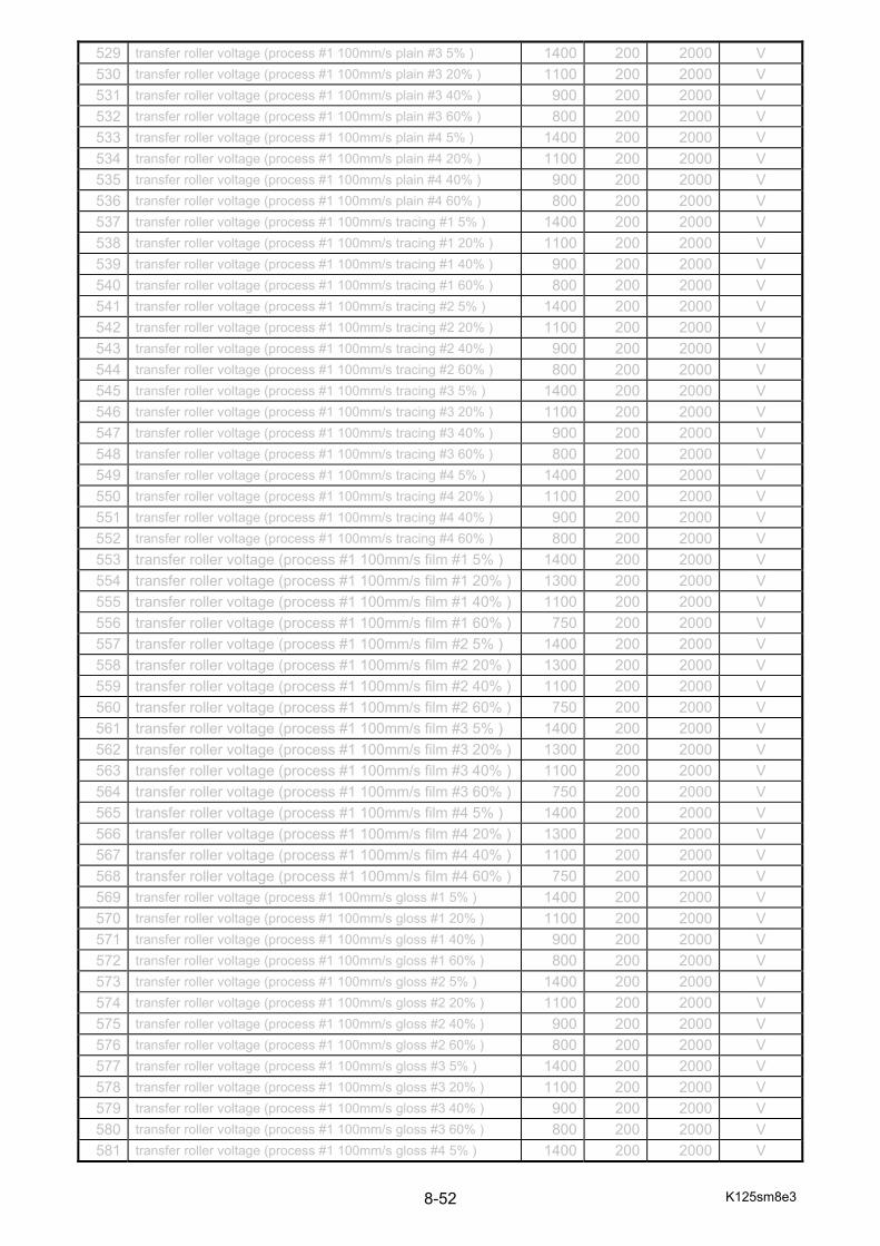
K125sm8e3 8-52
529 transfer roller voltage (process #1 100mm/s plain #3 5% ) 1400 200 2000 V
530 transfer roller voltage (process #1 100mm/s plain #3 20% ) 1100 200 2000 V
531 transfer roller voltage (process #1 100mm/s plain #3 40% ) 900 200 2000 V
532 transfer roller voltage (process #1 100mm/s plain #3 60% ) 800 200 2000 V
533 transfer roller voltage (process #1 100mm/s plain #4 5% ) 1400 200 2000 V
534 transfer roller voltage (process #1 100mm/s plain #4 20% ) 1100 200 2000 V
535 transfer roller voltage (process #1 100mm/s plain #4 40% ) 900 200 2000 V
536 transfer roller voltage (process #1 100mm/s plain #4 60% ) 800 200 2000 V
537 transfer roller voltage (process #1 100mm/s tracing #1 5% ) 1400 200 2000 V
538 transfer roller voltage (process #1 100mm/s tracing #1 20% ) 1100 200 2000 V
539 transfer roller voltage (process #1 100mm/s tracing #1 40% ) 900 200 2000 V
540 transfer roller voltage (process #1 100mm/s tracing #1 60% ) 800 200 2000 V
541 transfer roller voltage (process #1 100mm/s tracing #2 5% ) 1400 200 2000 V
542 transfer roller voltage (process #1 100mm/s tracing #2 20% ) 1100 200 2000 V
543 transfer roller voltage (process #1 100mm/s tracing #2 40% ) 900 200 2000 V
544 transfer roller voltage (process #1 100mm/s tracing #2 60% ) 800 200 2000 V
545 transfer roller voltage (process #1 100mm/s tracing #3 5% ) 1400 200 2000 V
546 transfer roller voltage (process #1 100mm/s tracing #3 20% ) 1100 200 2000 V
547 transfer roller voltage (process #1 100mm/s tracing #3 40% ) 900 200 2000 V
548 transfer roller voltage (process #1 100mm/s tracing #3 60% ) 800 200 2000 V
549 transfer roller voltage (process #1 100mm/s tracing #4 5% ) 1400 200 2000 V
550 transfer roller voltage (process #1 100mm/s tracing #4 20% ) 1100 200 2000 V
551 transfer roller voltage (process #1 100mm/s tracing #4 40% ) 900 200 2000 V
552 transfer roller voltage (process #1 100mm/s tracing #4 60% ) 800 200 2000 V
553 transfer roller voltage (process #1 100mm/s film #1 5% ) 1400 200 2000 V
554 transfer roller voltage (process #1 100mm/s film #1 20% ) 1300 200 2000 V
555 transfer roller voltage (process #1 100mm/s film #1 40% ) 1100 200 2000 V
556 transfer roller voltage (process #1 100mm/s film #1 60% ) 750 200 2000 V
557 transfer roller voltage (process #1 100mm/s film #2 5% ) 1400 200 2000 V
558 transfer roller voltage (process #1 100mm/s film #2 20% ) 1300 200 2000 V
559 transfer roller voltage (process #1 100mm/s film #2 40% ) 1100 200 2000 V
560 transfer roller voltage (process #1 100mm/s film #2 60% ) 750 200 2000 V
561 transfer roller voltage (process #1 100mm/s film #3 5% ) 1400 200 2000 V
562 transfer roller voltage (process #1 100mm/s film #3 20% ) 1300 200 2000 V
563 transfer roller voltage (process #1 100mm/s film #3 40% ) 1100 200 2000 V
564 transfer roller voltage (process #1 100mm/s film #3 60% ) 750 200 2000 V
565 transfer roller voltage (process #1 100mm/s film #4 5% ) 1400 200 2000 V
566 transfer roller voltage (process #1 100mm/s film #4 20% ) 1300 200 2000 V
567 transfer roller voltage (process #1 100mm/s film #4 40% ) 1100 200 2000 V
568 transfer roller voltage (process #1 100mm/s film #4 60% ) 750 200 2000 V
569 transfer roller voltage (process #1 100mm/s gloss #1 5% ) 1400 200 2000 V
570 transfer roller voltage (process #1 100mm/s gloss #1 20% ) 1100 200 2000 V
571 transfer roller voltage (process #1 100mm/s gloss #1 40% ) 900 200 2000 V
572 transfer roller voltage (process #1 100mm/s gloss #1 60% ) 800 200 2000 V
573 transfer roller voltage (process #1 100mm/s gloss #2 5% ) 1400 200 2000 V
574 transfer roller voltage (process #1 100mm/s gloss #2 20% ) 1100 200 2000 V
575 transfer roller voltage (process #1 100mm/s gloss #2 40% ) 900 200 2000 V
576 transfer roller voltage (process #1 100mm/s gloss #2 60% ) 800 200 2000 V
577 transfer roller voltage (process #1 100mm/s gloss #3 5% ) 1400 200 2000 V
578 transfer roller voltage (process #1 100mm/s gloss #3 20% ) 1100 200 2000 V
579 transfer roller voltage (process #1 100mm/s gloss #3 40% ) 900 200 2000 V
580 transfer roller voltage (process #1 100mm/s gloss #3 60% ) 800 200 2000 V
581 transfer roller voltage (process #1 100mm/s gloss #4 5% ) 1400 200 2000 V
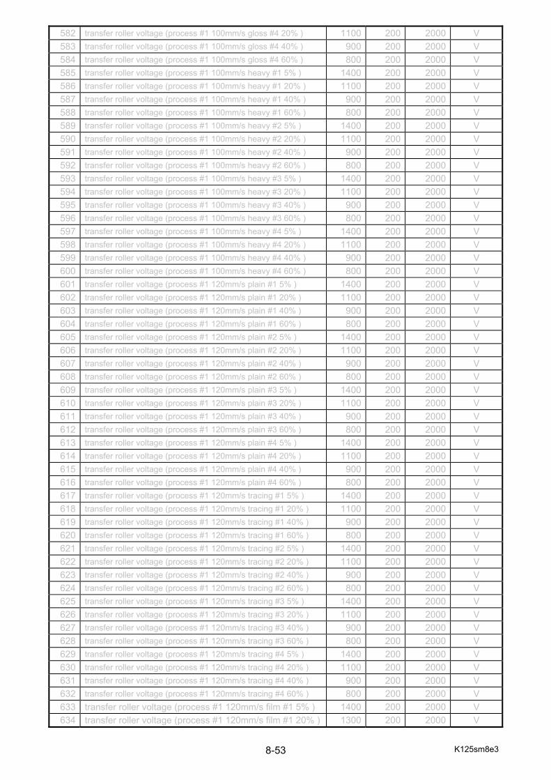
K125sm8e3 8-53
582 transfer roller voltage (process #1 100mm/s gloss #4 20% ) 1100 200 2000 V
583 transfer roller voltage (process #1 100mm/s gloss #4 40% ) 900 200 2000 V
584 transfer roller voltage (process #1 100mm/s gloss #4 60% ) 800 200 2000 V
585 transfer roller voltage (process #1 100mm/s heavy #1 5% ) 1400 200 2000 V
586 transfer roller voltage (process #1 100mm/s heavy #1 20% ) 1100 200 2000 V
587 transfer roller voltage (process #1 100mm/s heavy #1 40% ) 900 200 2000 V
588 transfer roller voltage (process #1 100mm/s heavy #1 60% ) 800 200 2000 V
589 transfer roller voltage (process #1 100mm/s heavy #2 5% ) 1400 200 2000 V
590 transfer roller voltage (process #1 100mm/s heavy #2 20% ) 1100 200 2000 V
591 transfer roller voltage (process #1 100mm/s heavy #2 40% ) 900 200 2000 V
592 transfer roller voltage (process #1 100mm/s heavy #2 60% ) 800 200 2000 V
593 transfer roller voltage (process #1 100mm/s heavy #3 5% ) 1400 200 2000 V
594 transfer roller voltage (process #1 100mm/s heavy #3 20% ) 1100 200 2000 V
595 transfer roller voltage (process #1 100mm/s heavy #3 40% ) 900 200 2000 V
596 transfer roller voltage (process #1 100mm/s heavy #3 60% ) 800 200 2000 V
597 transfer roller voltage (process #1 100mm/s heavy #4 5% ) 1400 200 2000 V
598 transfer roller voltage (process #1 100mm/s heavy #4 20% ) 1100 200 2000 V
599 transfer roller voltage (process #1 100mm/s heavy #4 40% ) 900 200 2000 V
600 transfer roller voltage (process #1 100mm/s heavy #4 60% ) 800 200 2000 V
601 transfer roller voltage (process #1 120mm/s plain #1 5% ) 1400 200 2000 V
602 transfer roller voltage (process #1 120mm/s plain #1 20% ) 1100 200 2000 V
603 transfer roller voltage (process #1 120mm/s plain #1 40% ) 900 200 2000 V
604 transfer roller voltage (process #1 120mm/s plain #1 60% ) 800 200 2000 V
605 transfer roller voltage (process #1 120mm/s plain #2 5% ) 1400 200 2000 V
606 transfer roller voltage (process #1 120mm/s plain #2 20% ) 1100 200 2000 V
607 transfer roller voltage (process #1 120mm/s plain #2 40% ) 900 200 2000 V
608 transfer roller voltage (process #1 120mm/s plain #2 60% ) 800 200 2000 V
609 transfer roller voltage (process #1 120mm/s plain #3 5% ) 1400 200 2000 V
610 transfer roller voltage (process #1 120mm/s plain #3 20% ) 1100 200 2000 V
611 transfer roller voltage (process #1 120mm/s plain #3 40% ) 900 200 2000 V
612 transfer roller voltage (process #1 120mm/s plain #3 60% ) 800 200 2000 V
613 transfer roller voltage (process #1 120mm/s plain #4 5% ) 1400 200 2000 V
614 transfer roller voltage (process #1 120mm/s plain #4 20% ) 1100 200 2000 V
615 transfer roller voltage (process #1 120mm/s plain #4 40% ) 900 200 2000 V
616 transfer roller voltage (process #1 120mm/s plain #4 60% ) 800 200 2000 V
617 transfer roller voltage (process #1 120mm/s tracing #1 5% ) 1400 200 2000 V
618 transfer roller voltage (process #1 120mm/s tracing #1 20% ) 1100 200 2000 V
619 transfer roller voltage (process #1 120mm/s tracing #1 40% ) 900 200 2000 V
620 transfer roller voltage (process #1 120mm/s tracing #1 60% ) 800 200 2000 V
621 transfer roller voltage (process #1 120mm/s tracing #2 5% ) 1400 200 2000 V
622 transfer roller voltage (process #1 120mm/s tracing #2 20% ) 1100 200 2000 V
623 transfer roller voltage (process #1 120mm/s tracing #2 40% ) 900 200 2000 V
624 transfer roller voltage (process #1 120mm/s tracing #2 60% ) 800 200 2000 V
625 transfer roller voltage (process #1 120mm/s tracing #3 5% ) 1400 200 2000 V
626 transfer roller voltage (process #1 120mm/s tracing #3 20% ) 1100 200 2000 V
627 transfer roller voltage (process #1 120mm/s tracing #3 40% ) 900 200 2000 V
628 transfer roller voltage (process #1 120mm/s tracing #3 60% ) 800 200 2000 V
629 transfer roller voltage (process #1 120mm/s tracing #4 5% ) 1400 200 2000 V
630 transfer roller voltage (process #1 120mm/s tracing #4 20% ) 1100 200 2000 V
631 transfer roller voltage (process #1 120mm/s tracing #4 40% ) 900 200 2000 V
632 transfer roller voltage (process #1 120mm/s tracing #4 60% ) 800 200 2000 V
633 transfer roller voltage (process #1 120mm/s film #1 5% ) 1400 200 2000 V
634 transfer roller voltage (process #1 120mm/s film #1 20% ) 1300 200 2000 V

K125sm8e3 8-54
635 transfer roller voltage (process #1 120mm/s film #1 40% ) 1100 200 2000 V
636 transfer roller voltage (process #1 120mm/s film #1 60% ) 750 200 2000 V
637 transfer roller voltage (process #1 120mm/s film #2 5% ) 1400 200 2000 V
638 transfer roller voltage (process #1 120mm/s film #2 20% ) 1300 200 2000 V
639 transfer roller voltage (process #1 120mm/s film #2 40% ) 1100 200 2000 V
640 transfer roller voltage (process #1 120mm/s film #2 60% ) 750 200 2000 V
641 transfer roller voltage (process #1 120mm/s film #3 5% ) 1400 200 2000 V
642 transfer roller voltage (process #1 120mm/s film #3 20% ) 1300 200 2000 V
643 transfer roller voltage (process #1 120mm/s film #3 40% ) 1100 200 2000 V
644 transfer roller voltage (process #1 120mm/s film #3 60% ) 750 200 2000 V
645 transfer roller voltage (process #1 120mm/s film #4 5% ) 1400 200 2000 V
646 transfer roller voltage (process #1 120mm/s film #4 20% ) 1300 200 2000 V
647 transfer roller voltage (process #1 120mm/s film #4 40% ) 1100 200 2000 V
648 transfer roller voltage (process #1 120mm/s film #4 60% ) 750 200 2000 V
649 transfer roller voltage (process #1 120mm/s gloss #1 5% ) 1400 200 2000 V
650 transfer roller voltage (process #1 120mm/s gloss #1 20% ) 1100 200 2000 V
651 transfer roller voltage (process #1 120mm/s gloss #1 40% ) 900 200 2000 V
652 transfer roller voltage (process #1 120mm/s gloss #1 60% ) 800 200 2000 V
653 transfer roller voltage (process #1 120mm/s gloss #2 5% ) 1400 200 2000 V
654 transfer roller voltage (process #1 120mm/s gloss #2 20% ) 1100 200 2000 V
655 transfer roller voltage (process #1 120mm/s gloss #2 40% ) 900 200 2000 V
656 transfer roller voltage (process #1 120mm/s gloss #2 60% ) 800 200 2000 V
657 transfer roller voltage (process #1 120mm/s gloss #3 5% ) 1400 200 2000 V
658 transfer roller voltage (process #1 120mm/s gloss #3 20% ) 1100 200 2000 V
659 transfer roller voltage (process #1 120mm/s gloss #3 40% ) 900 200 2000 V
660 transfer roller voltage (process #1 120mm/s gloss #3 60% ) 800 200 2000 V
661 transfer roller voltage (process #1 120mm/s gloss #4 5% ) 1400 200 2000 V
662 transfer roller voltage (process #1 120mm/s gloss #4 20% ) 1100 200 2000 V
663 transfer roller voltage (process #1 120mm/s gloss #4 40% ) 900 200 2000 V
664 transfer roller voltage (process #1 120mm/s gloss #4 60% ) 800 200 2000 V
665 transfer roller voltage (process #1 120mm/s heavy #1 5% ) 1400 200 2000 V
666 transfer roller voltage (process #1 120mm/s heavy #1 20% ) 1100 200 2000 V
667 transfer roller voltage (process #1 120mm/s heavy #1 40% ) 900 200 2000 V
668 transfer roller voltage (process #1 120mm/s heavy #1 60% ) 800 200 2000 V
669 transfer roller voltage (process #1 120mm/s heavy #2 5% ) 1400 200 2000 V
670 transfer roller voltage (process #1 120mm/s heavy #2 20% ) 1100 200 2000 V
671 transfer roller voltage (process #1 120mm/s heavy #2 40% ) 900 200 2000 V
672 transfer roller voltage (process #1 120mm/s heavy #2 60% ) 800 200 2000 V
673 transfer roller voltage (process #1 120mm/s heavy #3 5% ) 1400 200 2000 V
674 transfer roller voltage (process #1 120mm/s heavy #3 20% ) 1100 200 2000 V
675 transfer roller voltage (process #1 120mm/s heavy #3 40% ) 900 200 2000 V
676 transfer roller voltage (process #1 120mm/s heavy #3 60% ) 800 200 2000 V
677 transfer roller voltage (process #1 120mm/s heavy #4 5% ) 1400 200 2000 V
678 transfer roller voltage (process #1 120mm/s heavy #4 20% ) 1100 200 2000 V
679 transfer roller voltage (process #1 120mm/s heavy #4 40% ) 900 200 2000 V
680 transfer roller voltage (process #1 120mm/s heavy #4 60% ) 800 200 2000 V
681 transfer roller voltage (process #2 60mm/s plain #1 5% ) 1400 200 2000 V
682 transfer roller voltage (process #2 60mm/s plain #1 20% ) 1100 200 2000 V
683 transfer roller voltage (process #2 60mm/s plain #1 40% ) 900 200 2000 V
684 transfer roller voltage (process #2 60mm/s plain #1 60% ) 800 200 2000 V
685 transfer roller voltage (process #2 60mm/s plain #2 5% ) 1400 200 2000 V
686 transfer roller voltage (process #2 60mm/s plain #2 20% ) 1100 200 2000 V
687 transfer roller voltage (process #2 60mm/s plain #2 40% ) 900 200 2000 V
K125sm8e3 8-55
688 transfer roller voltage (process #2 60mm/s plain #2 60% ) 800 200 2000 V
689 transfer roller voltage (process #2 60mm/s plain #3 5% ) 1400 200 2000 V
690 transfer roller voltage (process #2 60mm/s plain #3 20% ) 1100 200 2000 V
691 transfer roller voltage (process #2 60mm/s plain #3 40% ) 900 200 2000 V
692 transfer roller voltage (process #2 60mm/s plain #3 60% ) 800 200 2000 V
693 transfer roller voltage (process #2 60mm/s plain #4 5% ) 1400 200 2000 V
694 transfer roller voltage (process #2 60mm/s plain #4 20% ) 1100 200 2000 V
695 transfer roller voltage (process #2 60mm/s plain #4 40% ) 900 200 2000 V
696 transfer roller voltage (process #2 60mm/s plain #4 60% ) 800 200 2000 V
697 transfer roller voltage (process #2 60mm/s tracing #1 5% ) 1400 200 2000 V
698 transfer roller voltage (process #2 60mm/s tracing #1 20% ) 1100 200 2000 V
699 transfer roller voltage (process #2 60mm/s tracing #1 40% ) 900 200 2000 V
700 transfer roller voltage (process #2 60mm/s tracing #1 60% ) 800 200 2000 V
701 transfer roller voltage (process #2 60mm/s tracing #2 5% ) 1400 200 2000 V
702 transfer roller voltage (process #2 60mm/s tracing #2 20% ) 1100 200 2000 V
703 transfer roller voltage (process #2 60mm/s tracing #2 40% ) 900 200 2000 V
704 transfer roller voltage (process #2 60mm/s tracing #2 60% ) 800 200 2000 V
705 transfer roller voltage (process #2 60mm/s tracing #3 5% ) 1400 200 2000 V
706 transfer roller voltage (process #2 60mm/s tracing #3 20% ) 1100 200 2000 V
707 transfer roller voltage (process #2 60mm/s tracing #3 40% ) 900 200 2000 V
708 transfer roller voltage (process #2 60mm/s tracing #3 60% ) 800 200 2000 V
709 transfer roller voltage (process #2 60mm/s tracing #4 5% ) 1400 200 2000 V
710 transfer roller voltage (process #2 60mm/s tracing #4 20% ) 1100 200 2000 V
711 transfer roller voltage (process #2 60mm/s tracing #4 40% ) 900 200 2000 V
712 transfer roller voltage (process #2 60mm/s tracing #4 60% ) 800 200 2000 V
713 transfer roller voltage (process #2 60mm/s film #1 5% ) 1050 200 2000 V
714 transfer roller voltage (process #2 60mm/s film #1 20% ) 950 200 2000 V
715 transfer roller voltage (process #2 60mm/s film #1 40% ) 800 200 2000 V
716 transfer roller voltage (process #2 60mm/s film #1 60% ) 600 200 2000 V
717 transfer roller voltage (process #2 60mm/s film #2 5% ) 1050 200 2000 V
718 transfer roller voltage (process #2 60mm/s film #2 20% ) 950 200 2000 V
719 transfer roller voltage (process #2 60mm/s film #2 40% ) 800 200 2000 V
720 transfer roller voltage (process #2 60mm/s film #2 60% ) 600 200 2000 V
721 transfer roller voltage (process #2 60mm/s film #3 5% ) 1050 200 2000 V
722 transfer roller voltage (process #2 60mm/s film #3 20% ) 950 200 2000 V
723 transfer roller voltage (process #2 60mm/s film #3 40% ) 800 200 2000 V
724 transfer roller voltage (process #2 60mm/s film #3 60% ) 600 200 2000 V
725 transfer roller voltage (process #2 60mm/s film #4 5% ) 1050 200 2000 V
726 transfer roller voltage (process #2 60mm/s film #4 20% ) 950 200 2000 V
727 transfer roller voltage (process #2 60mm/s film #4 40% ) 800 200 2000 V
728 transfer roller voltage (process #2 60mm/s film #4 60% ) 600 200 2000 V
729 transfer roller voltage (process #2 60mm/s gloss #1 5% ) 1400 200 2000 V
730 transfer roller voltage (process #2 60mm/s gloss #1 20% ) 1100 200 2000 V
731 transfer roller voltage (process #2 60mm/s gloss #1 40% ) 900 200 2000 V
732 transfer roller voltage (process #2 60mm/s gloss #1 60% ) 800 200 2000 V
733 transfer roller voltage (process #2 60mm/s gloss #2 5% ) 1400 200 2000 V
734 transfer roller voltage (process #2 60mm/s gloss #2 20% ) 1100 200 2000 V
735 transfer roller voltage (process #2 60mm/s gloss #2 40% ) 900 200 2000 V
736 transfer roller voltage (process #2 60mm/s gloss #2 60% ) 800 200 2000 V
737 transfer roller voltage (process #2 60mm/s gloss #3 5% ) 1400 200 2000 V
738 transfer roller voltage (process #2 60mm/s gloss #3 20% ) 1100 200 2000 V
739 transfer roller voltage (process #2 60mm/s gloss #3 40% ) 900 200 2000 V
740 transfer roller voltage (process #2 60mm/s gloss #3 60% ) 800 200 2000 V

K125sm8e3 8-56
741 transfer roller voltage (process #2 60mm/s gloss #4 5% ) 1400 200 2000 V
742 transfer roller voltage (process #2 60mm/s gloss #4 20% ) 1100 200 2000 V
743 transfer roller voltage (process #2 60mm/s gloss #4 40% ) 900 200 2000 V
744 transfer roller voltage (process #2 60mm/s gloss #4 60% ) 800 200 2000 V
745 transfer roller voltage (process #2 60mm/s heavy #1 5% ) 1400 200 2000 V
746 transfer roller voltage (process #2 60mm/s heavy #1 20% ) 1100 200 2000 V
747 transfer roller voltage (process #2 60mm/s heavy #1 40% ) 900 200 2000 V
748 transfer roller voltage (process #2 60mm/s heavy #1 60% ) 800 200 2000 V
749 transfer roller voltage (process #2 60mm/s heavy #2 5% ) 1400 200 2000 V
750 transfer roller voltage (process #2 60mm/s heavy #2 20% ) 1100 200 2000 V
751 transfer roller voltage (process #2 60mm/s heavy #2 40% ) 900 200 2000 V
752 transfer roller voltage (process #2 60mm/s heavy #2 60% ) 800 200 2000 V
753 transfer roller voltage (process #2 60mm/s heavy #3 5% ) 1400 200 2000 V
754 transfer roller voltage (process #2 60mm/s heavy #3 20% ) 1100 200 2000 V
755 transfer roller voltage (process #2 60mm/s heavy #3 40% ) 900 200 2000 V
756 transfer roller voltage (process #2 60mm/s heavy #3 60% ) 800 200 2000 V
757 transfer roller voltage (process #2 60mm/s heavy #4 5% ) 1400 200 2000 V
758 transfer roller voltage (process #2 60mm/s heavy #4 20% ) 1100 200 2000 V
759 transfer roller voltage (process #2 60mm/s heavy #4 40% ) 900 200 2000 V
760 transfer roller voltage (process #2 60mm/s heavy #4 60% ) 800 200 2000 V
761 transfer roller voltage (process #2 100mm/s plain #1 5% ) 1400 200 2000 V
762 transfer roller voltage (process #2 100mm/s plain #1 20% ) 1100 200 2000 V
763 transfer roller voltage (process #2 100mm/s plain #1 40% ) 900 200 2000 V
764 transfer roller voltage (process #2 100mm/s plain #1 60% ) 800 200 2000 V
765 transfer roller voltage (process #2 100mm/s plain #2 5% ) 1400 200 2000 V
766 transfer roller voltage (process #2 100mm/s plain #2 20% ) 1100 200 2000 V
767 transfer roller voltage (process #2 100mm/s plain #2 40% ) 900 200 2000 V
768 transfer roller voltage (process #2 100mm/s plain #2 60% ) 800 200 2000 V
769 transfer roller voltage (process #2 100mm/s plain #3 5% ) 1400 200 2000 V
770 transfer roller voltage (process #2 100mm/s plain #3 20% ) 1100 200 2000 V
771 transfer roller voltage (process #2 100mm/s plain #3 40% ) 900 200 2000 V
772 transfer roller voltage (process #2 100mm/s plain #3 60% ) 800 200 2000 V
773 transfer roller voltage (process #2 100mm/s plain #4 5% ) 1400 200 2000 V
774 transfer roller voltage (process #2 100mm/s plain #4 20% ) 1100 200 2000 V
775 transfer roller voltage (process #2 100mm/s plain #4 40% ) 900 200 2000 V
776 transfer roller voltage (process #2 100mm/s plain #4 60% ) 800 200 2000 V
777 transfer roller voltage (process #2 100mm/s tracing #1 5% ) 1400 200 2000 V
778 transfer roller voltage (process #2 100mm/s tracing #1 20% ) 1100 200 2000 V
779 transfer roller voltage (process #2 100mm/s tracing #1 40% ) 900 200 2000 V
780 transfer roller voltage (process #2 100mm/s tracing #1 60% ) 800 200 2000 V
781 transfer roller voltage (process #2 100mm/s tracing #2 5% ) 1400 200 2000 V
782 transfer roller voltage (process #2 100mm/s tracing #2 20% ) 1100 200 2000 V
783 transfer roller voltage (process #2 100mm/s tracing #2 40% ) 900 200 2000 V
784 transfer roller voltage (process #2 100mm/s tracing #2 60% ) 800 200 2000 V
785 transfer roller voltage (process #2 100mm/s tracing #3 5% ) 1400 200 2000 V
786 transfer roller voltage (process #2 100mm/s tracing #3 20% ) 1100 200 2000 V
787 transfer roller voltage (process #2 100mm/s tracing #3 40% ) 900 200 2000 V
788 transfer roller voltage (process #2 100mm/s tracing #3 60% ) 800 200 2000 V
789 transfer roller voltage (process #2 100mm/s tracing #4 5% ) 1400 200 2000 V
790 transfer roller voltage (process #2 100mm/s tracing #4 20% ) 1100 200 2000 V
791 transfer roller voltage (process #2 100mm/s tracing #4 40% ) 900 200 2000 V
792 transfer roller voltage (process #2 100mm/s tracing #4 60% ) 800 200 2000 V
793 transfer roller voltage (process #2 100mm/s film #1 5% ) 1100 200 2000 V

K125sm8e3 8-57
794 transfer roller voltage (process #2 100mm/s film #1 20% ) 1000 200 2000 V
795 transfer roller voltage (process #2 100mm/s film #1 40% ) 850 200 2000 V
796 transfer roller voltage (process #2 100mm/s film #1 60% ) 600 200 2000 V
797 transfer roller voltage (process #2 100mm/s film #2 5% ) 1100 200 2000 V
798 transfer roller voltage (process #2 100mm/s film #2 20% ) 1000 200 2000 V
799 transfer roller voltage (process #2 100mm/s film #2 40% ) 850 200 2000 V
800 transfer roller voltage (process #2 100mm/s film #2 60% ) 600 200 2000 V
1481 transfer roller voltage (process #2 100mm/s film #3 5% ) 1100 200 2000 V
1482 transfer roller voltage (process #2 100mm/s film #3 20% ) 1000 200 2000 V
1483 transfer roller voltage (process #2 100mm/s film #3 40% ) 850 200 2000 V
1484 transfer roller voltage (process #2 100mm/s film #3 60% ) 600 200 2000 V
1485 transfer roller voltage (process #2 100mm/s film #4 5% ) 1100 200 2000 V
1486 transfer roller voltage (process #2 100mm/s film #4 20% ) 1000 200 2000 V
1487 transfer roller voltage (process #2 100mm/s film #4 40% ) 850 200 2000 V
1488 transfer roller voltage (process #2 100mm/s film #4 60% ) 600 200 2000 V
1489 transfer roller voltage (process #2 100mm/s gloss #1 5% ) 1400 200 2000 V
1490 transfer roller voltage (process #2 100mm/s gloss #1 20% ) 1100 200 2000 V
1491 transfer roller voltage (process #2 100mm/s gloss #1 40% ) 900 200 2000 V
1492 transfer roller voltage (process #2 100mm/s gloss #1 60% ) 800 200 2000 V
1493 transfer roller voltage (process #2 100mm/s gloss #2 5% ) 1400 200 2000 V
1494 transfer roller voltage (process #2 100mm/s gloss #2 20% ) 1100 200 2000 V
1495 transfer roller voltage (process #2 100mm/s gloss #2 40% ) 900 200 2000 V
1496 transfer roller voltage (process #2 100mm/s gloss #2 60% ) 800 200 2000 V
1497 transfer roller voltage (process #2 100mm/s gloss #3 5% ) 1400 200 2000 V
1498 transfer roller voltage (process #2 100mm/s gloss #3 20% ) 1100 200 2000 V
1499 transfer roller voltage (process #2 100mm/s gloss #3 40% ) 900 200 2000 V
1500 transfer roller voltage (process #2 100mm/s gloss #3 60% ) 800 200 2000 V
1501 transfer roller voltage (process #2 100mm/s gloss #4 5% ) 1400 200 2000 V
1502 transfer roller voltage (process #2 100mm/s gloss #4 20% ) 1100 200 2000 V
1503 transfer roller voltage (process #2 100mm/s gloss #4 40% ) 900 200 2000 V
1504 transfer roller voltage (process #2 100mm/s gloss #4 60% ) 800 200 2000 V
1505 transfer roller voltage (process #2 100mm/s heavy #1 5% ) 1400 200 2000 V
1506 transfer roller voltage (process #2 100mm/s heavy #1 20% ) 1100 200 2000 V
1507 transfer roller voltage (process #2 100mm/s heavy #1 40% ) 900 200 2000 V
1508 transfer roller voltage (process #2 100mm/s heavy #1 60% ) 800 200 2000 V
1509 transfer roller voltage (process #2 100mm/s heavy #2 5% ) 1400 200 2000 V
1510 transfer roller voltage (process #2 100mm/s heavy #2 20% ) 1100 200 2000 V
1511 transfer roller voltage (process #2 100mm/s heavy #2 40% ) 900 200 2000 V
1512 transfer roller voltage (process #2 100mm/s heavy #2 60% ) 800 200 2000 V
1513 transfer roller voltage (process #2 100mm/s heavy #3 5% ) 1400 200 2000 V
1514 transfer roller voltage (process #2 100mm/s heavy #3 20% ) 1100 200 2000 V
1515 transfer roller voltage (process #2 100mm/s heavy #3 40% ) 900 200 2000 V
1516 transfer roller voltage (process #2 100mm/s heavy #3 60% ) 800 200 2000 V
1517 transfer roller voltage (process #2 100mm/s heavy #4 5% ) 1400 200 2000 V
1518 transfer roller voltage (process #2 100mm/s heavy #4 20% ) 1100 200 2000 V
1519 transfer roller voltage (process #2 100mm/s heavy #4 40% ) 900 200 2000 V
1520 transfer roller voltage (process #2 100mm/s heavy #4 60% ) 800 200 2000 V
1521 transfer roller voltage (process #2 120mm/s plain #1 5% ) 1400 200 2000 V
1522 transfer roller voltage (process #2 120mm/s plain #1 20% ) 1100 200 2000 V
1523 transfer roller voltage (process #2 120mm/s plain #1 40% ) 900 200 2000 V
1524 transfer roller voltage (process #2 120mm/s plain #1 60% ) 800 200 2000 V
1525 transfer roller voltage (process #2 120mm/s plain #2 5% ) 1400 200 2000 V
1526 transfer roller voltage (process #2 120mm/s plain #2 20% ) 1100 200 2000 V
K125sm8e3 8-58
1527 transfer roller voltage (process #2 120mm/s plain #2 40% ) 900 200 2000 V
1528 transfer roller voltage (process #2 120mm/s plain #2 60% ) 800 200 2000 V
1529 transfer roller voltage (process #2 120mm/s plain #3 5% ) 1400 200 2000 V
1530 transfer roller voltage (process #2 120mm/s plain #3 20% ) 1100 200 2000 V
1531 transfer roller voltage (process #2 120mm/s plain #3 40% ) 900 200 2000 V
1532 transfer roller voltage (process #2 120mm/s plain #3 60% ) 800 200 2000 V
1533 transfer roller voltage (process #2 120mm/s plain #4 5% ) 1400 200 2000 V
1534 transfer roller voltage (process #2 120mm/s plain #4 20% ) 1100 200 2000 V
1535 transfer roller voltage (process #2 120mm/s plain #4 40% ) 900 200 2000 V
1536 transfer roller voltage (process #2 120mm/s plain #4 60% ) 800 200 2000 V
1537 transfer roller voltage (process #2 120mm/s tracing #1 5% ) 1400 200 2000 V
1538 transfer roller voltage (process #2 120mm/s tracing #1 20% ) 1100 200 2000 V
1539 transfer roller voltage (process #2 120mm/s tracing #1 40% ) 900 200 2000 V
1540 transfer roller voltage (process #2 120mm/s tracing #1 60% ) 800 200 2000 V
1541 transfer roller voltage (process #2 120mm/s tracing #2 5% ) 1400 200 2000 V
1542 transfer roller voltage (process #2 120mm/s tracing #2 20% ) 1100 200 2000 V
1543 transfer roller voltage (process #2 120mm/s tracing #2 40% ) 900 200 2000 V
1544 transfer roller voltage (process #2 120mm/s tracing #2 60% ) 800 200 2000 V
1545 transfer roller voltage (process #2 120mm/s tracing #3 5% ) 1400 200 2000 V
1546 transfer roller voltage (process #2 120mm/s tracing #3 20% ) 1100 200 2000 V
1547 transfer roller voltage (process #2 120mm/s tracing #3 40% ) 900 200 2000 V
1548 transfer roller voltage (process #2 120mm/s tracing #3 60% ) 800 200 2000 V
1549 transfer roller voltage (process #2 120mm/s tracing #4 5% ) 1400 200 2000 V
1550 transfer roller voltage (process #2 120mm/s tracing #4 20% ) 1100 200 2000 V
1551 transfer roller voltage (process #2 120mm/s tracing #4 40% ) 900 200 2000 V
1552 transfer roller voltage (process #2 120mm/s tracing #4 60% ) 800 200 2000 V
1553 transfer roller voltage (process #2 120mm/s film #1 5% ) 1100 200 2000 V
1554 transfer roller voltage (process #2 120mm/s film #1 20% ) 1000 200 2000 V
1555 transfer roller voltage (process #2 120mm/s film #1 40% ) 850 200 2000 V
1556 transfer roller voltage (process #2 120mm/s film #1 60% ) 600 200 2000 V
1557 transfer roller voltage (process #2 120mm/s film #2 5% ) 1100 200 2000 V
1558 transfer roller voltage (process #2 120mm/s film #2 20% ) 1000 200 2000 V
1559 transfer roller voltage (process #2 120mm/s film #2 40% ) 850 200 2000 V
1560 transfer roller voltage (process #2 120mm/s film #2 60% ) 600 200 2000 V
1561 transfer roller voltage (process #2 120mm/s film #3 5% ) 1100 200 2000 V
1562 transfer roller voltage (process #2 120mm/s film #3 20% ) 1000 200 2000 V
1563 transfer roller voltage (process #2 120mm/s film #3 40% ) 850 200 2000 V
1564 transfer roller voltage (process #2 120mm/s film #3 60% ) 600 200 2000 V
1565 transfer roller voltage (process #2 120mm/s film #4 5% ) 1100 200 2000 V
1566 transfer roller voltage (process #2 120mm/s film #4 20% ) 1000 200 2000 V
1567 transfer roller voltage (process #2 120mm/s film #4 40% ) 850 200 2000 V
1568 transfer roller voltage (process #2 120mm/s film #4 60% ) 600 200 2000 V
1569 transfer roller voltage (process #2 120mm/s gloss #1 5% ) 1400 200 2000 V
1570 transfer roller voltage (process #2 120mm/s gloss #1 20% ) 1100 200 2000 V
1571 transfer roller voltage (process #2 120mm/s gloss #1 40% ) 900 200 2000 V
1572 transfer roller voltage (process #2 120mm/s gloss #1 60% ) 800 200 2000 V
1573 transfer roller voltage (process #2 120mm/s gloss #2 5% ) 1400 200 2000 V
1574 transfer roller voltage (process #2 120mm/s gloss #2 20% ) 1100 200 2000 V
1575 transfer roller voltage (process #2 120mm/s gloss #2 40% ) 900 200 2000 V
1576 transfer roller voltage (process #2 120mm/s gloss #2 60% ) 800 200 2000 V
1577 transfer roller voltage (process #2 120mm/s gloss #3 5% ) 1400 200 2000 V
1578 transfer roller voltage (process #2 120mm/s gloss #3 20% ) 1100 200 2000 V
1579 transfer roller voltage (process #2 120mm/s gloss #3 40% ) 900 200 2000 V

K125sm8e3 8-59
1580 transfer roller voltage (process #2 120mm/s gloss #3 60% ) 800 200 2000 V
1581 transfer roller voltage (process #2 120mm/s gloss #4 5% ) 1400 200 2000 V
1582 transfer roller voltage (process #2 120mm/s gloss #4 20% ) 1100 200 2000 V
1583 transfer roller voltage (process #2 120mm/s gloss #4 40% ) 900 200 2000 V
1584 transfer roller voltage (process #2 120mm/s gloss #4 60% ) 800 200 2000 V
1585 transfer roller voltage (process #2 120mm/s heavy #1 5% ) 1400 200 2000 V
1586 transfer roller voltage (process #2 120mm/s heavy #1 20% ) 1100 200 2000 V
1587 transfer roller voltage (process #2 120mm/s heavy #1 40% ) 900 200 2000 V
1588 transfer roller voltage (process #2 120mm/s heavy #1 60% ) 800 200 2000 V
1589 transfer roller voltage (process #2 120mm/s heavy #2 5% ) 1400 200 2000 V
1590 transfer roller voltage (process #2 120mm/s heavy #2 20% ) 1100 200 2000 V
1591 transfer roller voltage (process #2 120mm/s heavy #2 40% ) 900 200 2000 V
1592 transfer roller voltage (process #2 120mm/s heavy #2 60% ) 800 200 2000 V
1593 transfer roller voltage (process #2 120mm/s heavy #3 5% ) 1400 200 2000 V
1594 transfer roller voltage (process #2 120mm/s heavy #3 20% ) 1100 200 2000 V
1595 transfer roller voltage (process #2 120mm/s heavy #3 40% ) 900 200 2000 V
1596 transfer roller voltage (process #2 120mm/s heavy #3 60% ) 800 200 2000 V
1597 transfer roller voltage (process #2 120mm/s heavy #4 5% ) 1400 200 2000 V
1598 transfer roller voltage (process #2 120mm/s heavy #4 20% ) 1100 200 2000 V
1599 transfer roller voltage (process #2 120mm/s heavy #4 40% ) 900 200 2000 V
1600 transfer roller voltage (process #2 120mm/s heavy #4 60% ) 800 200 2000 V
1601 transfer roller voltage (process #3 60mm/s plain #1 5% ) 1400 200 2000 V
1602 transfer roller voltage (process #3 60mm/s plain #1 20% ) 1100 200 2000 V
1603 transfer roller voltage (process #3 60mm/s plain #1 40% ) 900 200 2000 V
1604 transfer roller voltage (process #3 60mm/s plain #1 60% ) 800 200 2000 V
1605 transfer roller voltage (process #3 60mm/s plain #2 5% ) 1400 200 2000 V
1606 transfer roller voltage (process #3 60mm/s plain #2 20% ) 1100 200 2000 V
1607 transfer roller voltage (process #3 60mm/s plain #2 40% ) 900 200 2000 V
1608 transfer roller voltage (process #3 60mm/s plain #2 60% ) 800 200 2000 V
1609 transfer roller voltage (process #3 60mm/s plain #3 5% ) 1400 200 2000 V
1610 transfer roller voltage (process #3 60mm/s plain #3 20% ) 1100 200 2000 V
1611 transfer roller voltage (process #3 60mm/s plain #3 40% ) 900 200 2000 V
1612 transfer roller voltage (process #3 60mm/s plain #3 60% ) 800 200 2000 V
1613 transfer roller voltage (process #3 60mm/s plain #4 5% ) 1400 200 2000 V
1614 transfer roller voltage (process #3 60mm/s plain #4 20% ) 1100 200 2000 V
1615 transfer roller voltage (process #3 60mm/s plain #4 40% ) 900 200 2000 V
1616 transfer roller voltage (process #3 60mm/s plain #4 60% ) 800 200 2000 V
1617 transfer roller voltage (process #3 60mm/s tracing #1 5% ) 1400 200 2000 V
1618 transfer roller voltage (process #3 60mm/s tracing #1 20% ) 1100 200 2000 V
1619 transfer roller voltage (process #3 60mm/s tracing #1 40% ) 900 200 2000 V
1620 transfer roller voltage (process #3 60mm/s tracing #1 60% ) 800 200 2000 V
1621 transfer roller voltage (process #3 60mm/s tracing #2 5% ) 1400 200 2000 V
1622 transfer roller voltage (process #3 60mm/s tracing #2 20% ) 1100 200 2000 V
1623 transfer roller voltage (process #3 60mm/s tracing #2 40% ) 900 200 2000 V
1624 transfer roller voltage (process #3 60mm/s tracing #2 60% ) 800 200 2000 V
1625 transfer roller voltage (process #3 60mm/s tracing #3 5% ) 1400 200 2000 V
1626 transfer roller voltage (process #3 60mm/s tracing #3 20% ) 1100 200 2000 V
1627 transfer roller voltage (process #3 60mm/s tracing #3 40% ) 900 200 2000 V
1628 transfer roller voltage (process #3 60mm/s tracing #3 60% ) 800 200 2000 V
1629 transfer roller voltage (process #3 60mm/s tracing #4 5% ) 1400 200 2000 V
1630 transfer roller voltage (process #3 60mm/s tracing #4 20% ) 1100 200 2000 V
1631 transfer roller voltage (process #3 60mm/s tracing #4 40% ) 900 200 2000 V
1632 transfer roller voltage (process #3 60mm/s tracing #4 60% ) 800 200 2000 V

K125sm8e3 8-60
1633 transfer roller voltage (process #3 60mm/s film #1 5% ) 800 200 2000 V
1634 transfer roller voltage (process #3 60mm/s film #1 20% ) 700 200 2000 V
1635 transfer roller voltage (process #3 60mm/s film #1 40% ) 600 200 2000 V
1636 transfer roller voltage (process #3 60mm/s film #1 60% ) 450 200 2000 V
1637 transfer roller voltage (process #3 60mm/s film #2 5% ) 800 200 2000 V
1638 transfer roller voltage (process #3 60mm/s film #2 20% ) 700 200 2000 V
1639 transfer roller voltage (process #3 60mm/s film #2 40% ) 600 200 2000 V
1640 transfer roller voltage (process #3 60mm/s film #2 60% ) 450 200 2000 V
1641 transfer roller voltage (process #3 60mm/s film #3 5% ) 800 200 2000 V
1642 transfer roller voltage (process #3 60mm/s film #3 20% ) 700 200 2000 V
1643 transfer roller voltage (process #3 60mm/s film #3 40% ) 600 200 2000 V
1644 transfer roller voltage (process #3 60mm/s film #3 60% ) 450 200 2000 V
1645 transfer roller voltage (process #3 60mm/s film #4 5% ) 800 200 2000 V
1646 transfer roller voltage (process #3 60mm/s film #4 20% ) 700 200 2000 V
1647 transfer roller voltage (process #3 60mm/s film #4 40% ) 600 200 2000 V
1648 transfer roller voltage (process #3 60mm/s film #4 60% ) 450 200 2000 V
1649 transfer roller voltage (process #3 60mm/s gloss #1 5% ) 1400 200 2000 V
1650 transfer roller voltage (process #3 60mm/s gloss #1 20% ) 1100 200 2000 V
1651 transfer roller voltage (process #3 60mm/s gloss #1 40% ) 900 200 2000 V
1652 transfer roller voltage (process #3 60mm/s gloss #1 60% ) 800 200 2000 V
1653 transfer roller voltage (process #3 60mm/s gloss #2 5% ) 1400 200 2000 V
1654 transfer roller voltage (process #3 60mm/s gloss #2 20% ) 1100 200 2000 V
1655 transfer roller voltage (process #3 60mm/s gloss #2 40% ) 900 200 2000 V
1656 transfer roller voltage (process #3 60mm/s gloss #2 60% ) 800 200 2000 V
1657 transfer roller voltage (process #3 60mm/s gloss #3 5% ) 1400 200 2000 V
1658 transfer roller voltage (process #3 60mm/s gloss #3 20% ) 1100 200 2000 V
1659 transfer roller voltage (process #3 60mm/s gloss #3 40% ) 900 200 2000 V
1660 transfer roller voltage (process #3 60mm/s gloss #3 60% ) 800 200 2000 V
1661 transfer roller voltage (process #3 60mm/s gloss #4 5% ) 1400 200 2000 V
1662 transfer roller voltage (process #3 60mm/s gloss #4 20% ) 1100 200 2000 V
1663 transfer roller voltage (process #3 60mm/s gloss #4 40% ) 900 200 2000 V
1664 transfer roller voltage (process #3 60mm/s gloss #4 60% ) 800 200 2000 V
1665 transfer roller voltage (process #3 60mm/s heavy #1 5% ) 1400 200 2000 V
1666 transfer roller voltage (process #3 60mm/s heavy #1 20% ) 1100 200 2000 V
1667 transfer roller voltage (process #3 60mm/s heavy #1 40% ) 900 200 2000 V
1668 transfer roller voltage (process #3 60mm/s heavy #1 60% ) 800 200 2000 V
1669 transfer roller voltage (process #3 60mm/s heavy #2 5% ) 1400 200 2000 V
1670 transfer roller voltage (process #3 60mm/s heavy #2 20% ) 1100 200 2000 V
1671 transfer roller voltage (process #3 60mm/s heavy #2 40% ) 900 200 2000 V
1672 transfer roller voltage (process #3 60mm/s heavy #2 60% ) 800 200 2000 V
1673 transfer roller voltage (process #3 60mm/s heavy #3 5% ) 1400 200 2000 V
1674 transfer roller voltage (process #3 60mm/s heavy #3 20% ) 1100 200 2000 V
1675 transfer roller voltage (process #3 60mm/s heavy #3 40% ) 900 200 2000 V
1676 transfer roller voltage (process #3 60mm/s heavy #3 60% ) 800 200 2000 V
1677 transfer roller voltage (process #3 60mm/s heavy #4 5% ) 1400 200 2000 V
1678 transfer roller voltage (process #3 60mm/s heavy #4 20% ) 1100 200 2000 V
1679 transfer roller voltage (process #3 60mm/s heavy #4 40% ) 900 200 2000 V
1680 transfer roller voltage (process #3 60mm/s heavy #4 60% ) 800 200 2000 V
1681 transfer roller voltage (process #3 100mm/s plain #1 5% ) 1400 200 2000 V
1682 transfer roller voltage (process #3 100mm/s plain #1 20% ) 1100 200 2000 V
1683 transfer roller voltage (process #3 100mm/s plain #1 40% ) 900 200 2000 V
1684 transfer roller voltage (process #3 100mm/s plain #1 60% ) 800 200 2000 V
1685 transfer roller voltage (process #3 100mm/s plain #2 5% ) 1400 200 2000 V
K125sm8e3 8-61
1686 transfer roller voltage (process #3 100mm/s plain #2 20% ) 1100 200 2000 V
1687 transfer roller voltage (process #3 100mm/s plain #2 40% ) 900 200 2000 V
1688 transfer roller voltage (process #3 100mm/s plain #2 60% ) 800 200 2000 V
1689 transfer roller voltage (process #3 100mm/s plain #3 5% ) 1400 200 2000 V
1690 transfer roller voltage (process #3 100mm/s plain #3 20% ) 1100 200 2000 V
1691 transfer roller voltage (process #3 100mm/s plain #3 40% ) 900 200 2000 V
1692 transfer roller voltage (process #3 100mm/s plain #3 60% ) 800 200 2000 V
1693 transfer roller voltage (process #3 100mm/s plain #4 5% ) 1400 200 2000 V
1694 transfer roller voltage (process #3 100mm/s plain #4 20% ) 1100 200 2000 V
1695 transfer roller voltage (process #3 100mm/s plain #4 40% ) 900 200 2000 V
1696 transfer roller voltage (process #3 100mm/s plain #4 60% ) 800 200 2000 V
1697 transfer roller voltage (process #3 100mm/s tracing #1 5% ) 1400 200 2000 V
1698 transfer roller voltage (process #3 100mm/s tracing #1 20% ) 1100 200 2000 V
1699 transfer roller voltage (process #3 100mm/s tracing #1 40% ) 900 200 2000 V
1700 transfer roller voltage (process #3 100mm/s tracing #1 60% ) 800 200 2000 V
1701 transfer roller voltage (process #3 100mm/s tracing #2 5% ) 1400 200 2000 V
1702 transfer roller voltage (process #3 100mm/s tracing #2 20% ) 1100 200 2000 V
1703 transfer roller voltage (process #3 100mm/s tracing #2 40% ) 900 200 2000 V
1704 transfer roller voltage (process #3 100mm/s tracing #2 60% ) 800 200 2000 V
1705 transfer roller voltage (process #3 100mm/s tracing #3 5% ) 1400 200 2000 V
1706 transfer roller voltage (process #3 100mm/s tracing #3 20% ) 1100 200 2000 V
1707 transfer roller voltage (process #3 100mm/s tracing #3 40% ) 900 200 2000 V
1708 transfer roller voltage (process #3 100mm/s tracing #3 60% ) 800 200 2000 V
1709 transfer roller voltage (process #3 100mm/s tracing #4 5% ) 1400 200 2000 V
1710 transfer roller voltage (process #3 100mm/s tracing #4 20% ) 1100 200 2000 V
1711 transfer roller voltage (process #3 100mm/s tracing #4 40% ) 900 200 2000 V
1712 transfer roller voltage (process #3 100mm/s tracing #4 60% ) 800 200 2000 V
1713 transfer roller voltage (process #3 100mm/s film #1 5% ) 800 200 2000 V
1714 transfer roller voltage (process #3 100mm/s film #1 20% ) 700 200 2000 V
1715 transfer roller voltage (process #3 100mm/s film #1 40% ) 600 200 2000 V
1716 transfer roller voltage (process #3 100mm/s film #1 60% ) 450 200 2000 V
1717 transfer roller voltage (process #3 100mm/s film #2 5% ) 800 200 2000 V
1718 transfer roller voltage (process #3 100mm/s film #2 20% ) 700 200 2000 V
1719 transfer roller voltage (process #3 100mm/s film #2 40% ) 600 200 2000 V
1720 transfer roller voltage (process #3 100mm/s film #2 60% ) 450 200 2000 V
1721 transfer roller voltage (process #3 100mm/s film #3 5% ) 800 200 2000 V
1722 transfer roller voltage (process #3 100mm/s film #3 20% ) 700 200 2000 V
1723 transfer roller voltage (process #3 100mm/s film #3 40% ) 600 200 2000 V
1724 transfer roller voltage (process #3 100mm/s film #3 60% ) 450 200 2000 V
1725 transfer roller voltage (process #3 100mm/s film #4 5% ) 800 200 2000 V
1726 transfer roller voltage (process #3 100mm/s film #4 20% ) 700 200 2000 V
1727 transfer roller voltage (process #3 100mm/s film #4 40% ) 600 200 2000 V
1728 transfer roller voltage (process #3 100mm/s film #4 60% ) 450 200 2000 V
1729 transfer roller voltage (process #3 100mm/s gloss #1 5% ) 1400 200 2000 V
1730 transfer roller voltage (process #3 100mm/s gloss #1 20% ) 1100 200 2000 V
1731 transfer roller voltage (process #3 100mm/s gloss #1 40% ) 900 200 2000 V
1732 transfer roller voltage (process #3 100mm/s gloss #1 60% ) 800 200 2000 V
1733 transfer roller voltage (process #3 100mm/s gloss #2 5% ) 1400 200 2000 V
1734 transfer roller voltage (process #3 100mm/s gloss #2 20% ) 1100 200 2000 V
1735 transfer roller voltage (process #3 100mm/s gloss #2 40% ) 900 200 2000 V
1736 transfer roller voltage (process #3 100mm/s gloss #2 60% ) 800 200 2000 V
1737 transfer roller voltage (process #3 100mm/s gloss #3 5% ) 1400 200 2000 V
1738 transfer roller voltage (process #3 100mm/s gloss #3 20% ) 1100 200 2000 V
K125sm8e3 8-62
1739 transfer roller voltage (process #3 100mm/s gloss #3 40% ) 900 200 2000 V
1740 transfer roller voltage (process #3 100mm/s gloss #3 60% ) 800 200 2000 V
1741 transfer roller voltage (process #3 100mm/s gloss #4 5% ) 1400 200 2000 V
1742 transfer roller voltage (process #3 100mm/s gloss #4 20% ) 1100 200 2000 V
1743 transfer roller voltage (process #3 100mm/s gloss #4 40% ) 900 200 2000 V
1744 transfer roller voltage (process #3 100mm/s gloss #4 60% ) 800 200 2000 V
1745 transfer roller voltage (process #3 100mm/s heavy #1 5% ) 1400 200 2000 V
1746 transfer roller voltage (process #3 100mm/s heavy #1 20% ) 1100 200 2000 V
1747 transfer roller voltage (process #3 100mm/s heavy #1 40% ) 900 200 2000 V
1748 transfer roller voltage (process #3 100mm/s heavy #1 60% ) 800 200 2000 V
1749 transfer roller voltage (process #3 100mm/s heavy #2 5% ) 1400 200 2000 V
1750 transfer roller voltage (process #3 100mm/s heavy #2 20% ) 1100 200 2000 V
1751 transfer roller voltage (process #3 100mm/s heavy #2 40% ) 900 200 2000 V
1752 transfer roller voltage (process #3 100mm/s heavy #2 60% ) 800 200 2000 V
1753 transfer roller voltage (process #3 100mm/s heavy #3 5% ) 1400 200 2000 V
1754 transfer roller voltage (process #3 100mm/s heavy #3 20% ) 1100 200 2000 V
1755 transfer roller voltage (process #3 100mm/s heavy #3 40% ) 900 200 2000 V
1756 transfer roller voltage (process #3 100mm/s heavy #3 60% ) 800 200 2000 V
1757 transfer roller voltage (process #3 100mm/s heavy #4 5% ) 1400 200 2000 V
1758 transfer roller voltage (process #3 100mm/s heavy #4 20% ) 1100 200 2000 V
1759 transfer roller voltage (process #3 100mm/s heavy #4 40% ) 900 200 2000 V
1760 transfer roller voltage (process #3 100mm/s heavy #4 60% ) 800 200 2000 V
1761 transfer roller voltage (process #3 120mm/s plain #1 5% ) 1400 200 2000 V
1762 transfer roller voltage (process #3 120mm/s plain #1 20% ) 1100 200 2000 V
1763 transfer roller voltage (process #3 120mm/s plain #1 40% ) 900 200 2000 V
1764 transfer roller voltage (process #3 120mm/s plain #1 60% ) 800 200 2000 V
1765 transfer roller voltage (process #3 120mm/s plain #2 5% ) 1400 200 2000 V
1766 transfer roller voltage (process #3 120mm/s plain #2 20% ) 1100 200 2000 V
1767 transfer roller voltage (process #3 120mm/s plain #2 40% ) 900 200 2000 V
1768 transfer roller voltage (process #3 120mm/s plain #2 60% ) 800 200 2000 V
1769 transfer roller voltage (process #3 120mm/s plain #3 5% ) 1400 200 2000 V
1770 transfer roller voltage (process #3 120mm/s plain #3 20% ) 1100 200 2000 V
1771 transfer roller voltage (process #3 120mm/s plain #3 40% ) 900 200 2000 V
1772 transfer roller voltage (process #3 120mm/s plain #3 60% ) 800 200 2000 V
1773 transfer roller voltage (process #3 120mm/s plain #4 5% ) 1400 200 2000 V
1774 transfer roller voltage (process #3 120mm/s plain #4 20% ) 1100 200 2000 V
1775 transfer roller voltage (process #3 120mm/s plain #4 40% ) 900 200 2000 V
1776 transfer roller voltage (process #3 120mm/s plain #4 60% ) 800 200 2000 V
1777 transfer roller voltage (process #3 120mm/s tracing #1 5% ) 1400 200 2000 V
1778 transfer roller voltage (process #3 120mm/s tracing #1 20% ) 1100 200 2000 V
1779 transfer roller voltage (process #3 120mm/s tracing #1 40% ) 900 200 2000 V
1780 transfer roller voltage (process #3 120mm/s tracing #1 60% ) 800 200 2000 V
1781 transfer roller voltage (process #3 120mm/s tracing #2 5% ) 1400 200 2000 V
1782 transfer roller voltage (process #3 120mm/s tracing #2 20% ) 1100 200 2000 V
1783 transfer roller voltage (process #3 120mm/s tracing #2 40% ) 900 200 2000 V
1784 transfer roller voltage (process #3 120mm/s tracing #2 60% ) 800 200 2000 V
1785 transfer roller voltage (process #3 120mm/s tracing #3 5% ) 1400 200 2000 V
1786 transfer roller voltage (process #3 120mm/s tracing #3 20% ) 1100 200 2000 V
1787 transfer roller voltage (process #3 120mm/s tracing #3 40% ) 900 200 2000 V
1788 transfer roller voltage (process #3 120mm/s tracing #3 60% ) 800 200 2000 V
1789 transfer roller voltage (process #3 120mm/s tracing #4 5% ) 1400 200 2000 V
1790 transfer roller voltage (process #3 120mm/s tracing #4 20% ) 1100 200 2000 V
1791 transfer roller voltage (process #3 120mm/s tracing #4 40% ) 900 200 2000 V
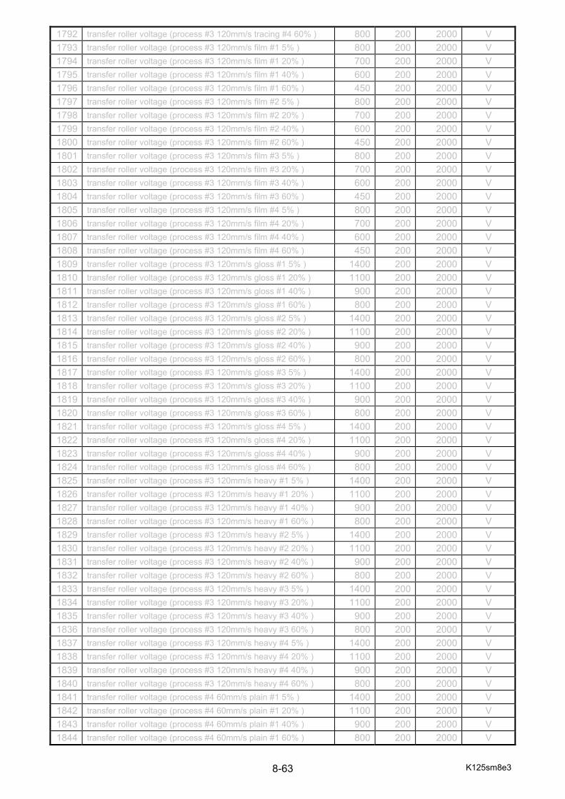
K125sm8e3 8-63
1792 transfer roller voltage (process #3 120mm/s tracing #4 60% ) 800 200 2000 V
1793 transfer roller voltage (process #3 120mm/s film #1 5% ) 800 200 2000 V
1794 transfer roller voltage (process #3 120mm/s film #1 20% ) 700 200 2000 V
1795 transfer roller voltage (process #3 120mm/s film #1 40% ) 600 200 2000 V
1796 transfer roller voltage (process #3 120mm/s film #1 60% ) 450 200 2000 V
1797 transfer roller voltage (process #3 120mm/s film #2 5% ) 800 200 2000 V
1798 transfer roller voltage (process #3 120mm/s film #2 20% ) 700 200 2000 V
1799 transfer roller voltage (process #3 120mm/s film #2 40% ) 600 200 2000 V
1800 transfer roller voltage (process #3 120mm/s film #2 60% ) 450 200 2000 V
1801 transfer roller voltage (process #3 120mm/s film #3 5% ) 800 200 2000 V
1802 transfer roller voltage (process #3 120mm/s film #3 20% ) 700 200 2000 V
1803 transfer roller voltage (process #3 120mm/s film #3 40% ) 600 200 2000 V
1804 transfer roller voltage (process #3 120mm/s film #3 60% ) 450 200 2000 V
1805 transfer roller voltage (process #3 120mm/s film #4 5% ) 800 200 2000 V
1806 transfer roller voltage (process #3 120mm/s film #4 20% ) 700 200 2000 V
1807 transfer roller voltage (process #3 120mm/s film #4 40% ) 600 200 2000 V
1808 transfer roller voltage (process #3 120mm/s film #4 60% ) 450 200 2000 V
1809 transfer roller voltage (process #3 120mm/s gloss #1 5% ) 1400 200 2000 V
1810 transfer roller voltage (process #3 120mm/s gloss #1 20% ) 1100 200 2000 V
1811 transfer roller voltage (process #3 120mm/s gloss #1 40% ) 900 200 2000 V
1812 transfer roller voltage (process #3 120mm/s gloss #1 60% ) 800 200 2000 V
1813 transfer roller voltage (process #3 120mm/s gloss #2 5% ) 1400 200 2000 V
1814 transfer roller voltage (process #3 120mm/s gloss #2 20% ) 1100 200 2000 V
1815 transfer roller voltage (process #3 120mm/s gloss #2 40% ) 900 200 2000 V
1816 transfer roller voltage (process #3 120mm/s gloss #2 60% ) 800 200 2000 V
1817 transfer roller voltage (process #3 120mm/s gloss #3 5% ) 1400 200 2000 V
1818 transfer roller voltage (process #3 120mm/s gloss #3 20% ) 1100 200 2000 V
1819 transfer roller voltage (process #3 120mm/s gloss #3 40% ) 900 200 2000 V
1820 transfer roller voltage (process #3 120mm/s gloss #3 60% ) 800 200 2000 V
1821 transfer roller voltage (process #3 120mm/s gloss #4 5% ) 1400 200 2000 V
1822 transfer roller voltage (process #3 120mm/s gloss #4 20% ) 1100 200 2000 V
1823 transfer roller voltage (process #3 120mm/s gloss #4 40% ) 900 200 2000 V
1824 transfer roller voltage (process #3 120mm/s gloss #4 60% ) 800 200 2000 V
1825 transfer roller voltage (process #3 120mm/s heavy #1 5% ) 1400 200 2000 V
1826 transfer roller voltage (process #3 120mm/s heavy #1 20% ) 1100 200 2000 V
1827 transfer roller voltage (process #3 120mm/s heavy #1 40% ) 900 200 2000 V
1828 transfer roller voltage (process #3 120mm/s heavy #1 60% ) 800 200 2000 V
1829 transfer roller voltage (process #3 120mm/s heavy #2 5% ) 1400 200 2000 V
1830 transfer roller voltage (process #3 120mm/s heavy #2 20% ) 1100 200 2000 V
1831 transfer roller voltage (process #3 120mm/s heavy #2 40% ) 900 200 2000 V
1832 transfer roller voltage (process #3 120mm/s heavy #2 60% ) 800 200 2000 V
1833 transfer roller voltage (process #3 120mm/s heavy #3 5% ) 1400 200 2000 V
1834 transfer roller voltage (process #3 120mm/s heavy #3 20% ) 1100 200 2000 V
1835 transfer roller voltage (process #3 120mm/s heavy #3 40% ) 900 200 2000 V
1836 transfer roller voltage (process #3 120mm/s heavy #3 60% ) 800 200 2000 V
1837 transfer roller voltage (process #3 120mm/s heavy #4 5% ) 1400 200 2000 V
1838 transfer roller voltage (process #3 120mm/s heavy #4 20% ) 1100 200 2000 V
1839 transfer roller voltage (process #3 120mm/s heavy #4 40% ) 900 200 2000 V
1840 transfer roller voltage (process #3 120mm/s heavy #4 60% ) 800 200 2000 V
1841 transfer roller voltage (process #4 60mm/s plain #1 5% ) 1400 200 2000 V
1842 transfer roller voltage (process #4 60mm/s plain #1 20% ) 1100 200 2000 V
1843 transfer roller voltage (process #4 60mm/s plain #1 40% ) 900 200 2000 V
1844 transfer roller voltage (process #4 60mm/s plain #1 60% ) 800 200 2000 V

K125sm8e3 8-64
1845 transfer roller voltage (process #4 60mm/s plain #2 5% ) 1400 200 2000 V
1846 transfer roller voltage (process #4 60mm/s plain #2 20% ) 1100 200 2000 V
1847 transfer roller voltage (process #4 60mm/s plain #2 40% ) 900 200 2000 V
1848 transfer roller voltage (process #4 60mm/s plain #2 60% ) 800 200 2000 V
1849 transfer roller voltage (process #4 60mm/s plain #3 5% ) 1400 200 2000 V
1850 transfer roller voltage (process #4 60mm/s plain #3 20% ) 1100 200 2000 V
1851 transfer roller voltage (process #4 60mm/s plain #3 40% ) 900 200 2000 V
1852 transfer roller voltage (process #4 60mm/s plain #3 60% ) 800 200 2000 V
1853 transfer roller voltage (process #4 60mm/s plain #4 5% ) 1400 200 2000 V
1854 transfer roller voltage (process #4 60mm/s plain #4 20% ) 1100 200 2000 V
1855 transfer roller voltage (process #4 60mm/s plain #4 40% ) 900 200 2000 V
1856 transfer roller voltage (process #4 60mm/s plain #4 60% ) 800 200 2000 V
1857 transfer roller voltage (process #4 60mm/s tracing #1 5% ) 1400 200 2000 V
1858 transfer roller voltage (process #4 60mm/s tracing #1 20% ) 1100 200 2000 V
1859 transfer roller voltage (process #4 60mm/s tracing #1 40% ) 900 200 2000 V
1860 transfer roller voltage (process #4 60mm/s tracing #1 60% ) 800 200 2000 V
1861 transfer roller voltage (process #4 60mm/s tracing #2 5% ) 1400 200 2000 V
1862 transfer roller voltage (process #4 60mm/s tracing #2 20% ) 1100 200 2000 V
1863 transfer roller voltage (process #4 60mm/s tracing #2 40% ) 900 200 2000 V
1864 transfer roller voltage (process #4 60mm/s tracing #2 60% ) 800 200 2000 V
1865 transfer roller voltage (process #4 60mm/s tracing #3 5% ) 1400 200 2000 V
1866 transfer roller voltage (process #4 60mm/s tracing #3 20% ) 1100 200 2000 V
1867 transfer roller voltage (process #4 60mm/s tracing #3 40% ) 900 200 2000 V
1868 transfer roller voltage (process #4 60mm/s tracing #3 60% ) 800 200 2000 V
1869 transfer roller voltage (process #4 60mm/s tracing #4 5% ) 1400 200 2000 V
1870 transfer roller voltage (process #4 60mm/s tracing #4 20% ) 1100 200 2000 V
1871 transfer roller voltage (process #4 60mm/s tracing #4 40% ) 900 200 2000 V
1872 transfer roller voltage (process #4 60mm/s tracing #4 60% ) 800 200 2000 V
1873 transfer roller voltage (process #4 60mm/s film #1 5% ) 500 200 2000 V
1874 transfer roller voltage (process #4 60mm/s film #1 20% ) 400 200 2000 V
1875 transfer roller voltage (process #4 60mm/s film #1 40% ) 350 200 2000 V
1876 transfer roller voltage (process #4 60mm/s film #1 60% ) 300 200 2000 V
1877 transfer roller voltage (process #4 60mm/s film #2 5% ) 500 200 2000 V
1878 transfer roller voltage (process #4 60mm/s film #2 20% ) 400 200 2000 V
1879 transfer roller voltage (process #4 60mm/s film #2 40% ) 350 200 2000 V
1880 transfer roller voltage (process #4 60mm/s film #2 60% ) 300 200 2000 V
1881 transfer roller voltage (process #4 60mm/s film #3 5% ) 500 200 2000 V
1882 transfer roller voltage (process #4 60mm/s film #3 20% ) 400 200 2000 V
1883 transfer roller voltage (process #4 60mm/s film #3 40% ) 350 200 2000 V
1884 transfer roller voltage (process #4 60mm/s film #3 60% ) 300 200 2000 V
1885 transfer roller voltage (process #4 60mm/s film #4 5% ) 500 200 2000 V
1886 transfer roller voltage (process #4 60mm/s film #4 20% ) 400 200 2000 V
1887 transfer roller voltage (process #4 60mm/s film #4 40% ) 350 200 2000 V
1888 transfer roller voltage (process #4 60mm/s film #4 60% ) 300 200 2000 V
1889 transfer roller voltage (process #4 60mm/s gloss #1 5% ) 1400 200 2000 V
1890 transfer roller voltage (process #4 60mm/s gloss #1 20% ) 1100 200 2000 V
1891 transfer roller voltage (process #4 60mm/s gloss #1 40% ) 900 200 2000 V
1892 transfer roller voltage (process #4 60mm/s gloss #1 60% ) 800 200 2000 V
1893 transfer roller voltage (process #4 60mm/s gloss #2 5% ) 1400 200 2000 V
1894 transfer roller voltage (process #4 60mm/s gloss #2 20% ) 1100 200 2000 V
1895 transfer roller voltage (process #4 60mm/s gloss #2 40% ) 900 200 2000 V
1896 transfer roller voltage (process #4 60mm/s gloss #2 60% ) 800 200 2000 V
1897 transfer roller voltage (process #4 60mm/s gloss #3 5% ) 1400 200 2000 V
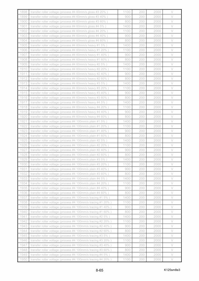
K125sm8e3 8-65
1898 transfer roller voltage (process #4 60mm/s gloss #3 20% ) 1100 200 2000 V
1899 transfer roller voltage (process #4 60mm/s gloss #3 40% ) 900 200 2000 V
1900 transfer roller voltage (process #4 60mm/s gloss #3 60% ) 800 200 2000 V
1901 transfer roller voltage (process #4 60mm/s gloss #4 5% ) 1400 200 2000 V
1902 transfer roller voltage (process #4 60mm/s gloss #4 20% ) 1100 200 2000 V
1903 transfer roller voltage (process #4 60mm/s gloss #4 40% ) 900 200 2000 V
1904 transfer roller voltage (process #4 60mm/s gloss #4 60% ) 800 200 2000 V
1905 transfer roller voltage (process #4 60mm/s heavy #1 5% ) 1400 200 2000 V
1906 transfer roller voltage (process #4 60mm/s heavy #1 20% ) 1100 200 2000 V
1907 transfer roller voltage (process #4 60mm/s heavy #1 40% ) 900 200 2000 V
1908 transfer roller voltage (process #4 60mm/s heavy #1 60% ) 800 200 2000 V
1909 transfer roller voltage (process #4 60mm/s heavy #2 5% ) 1400 200 2000 V
1910 transfer roller voltage (process #4 60mm/s heavy #2 20% ) 1100 200 2000 V
1911 transfer roller voltage (process #4 60mm/s heavy #2 40% ) 900 200 2000 V
1912 transfer roller voltage (process #4 60mm/s heavy #2 60% ) 800 200 2000 V
1913 transfer roller voltage (process #4 60mm/s heavy #3 5% ) 1400 200 2000 V
1914 transfer roller voltage (process #4 60mm/s heavy #3 20% ) 1100 200 2000 V
1915 transfer roller voltage (process #4 60mm/s heavy #3 40% ) 900 200 2000 V
1916 transfer roller voltage (process #4 60mm/s heavy #3 60% ) 800 200 2000 V
1917 transfer roller voltage (process #4 60mm/s heavy #4 5% ) 1400 200 2000 V
1918 transfer roller voltage (process #4 60mm/s heavy #4 20% ) 1100 200 2000 V
1919 transfer roller voltage (process #4 60mm/s heavy #4 40% ) 900 200 2000 V
1920 transfer roller voltage (process #4 60mm/s heavy #4 60% ) 800 200 2000 V
1921 transfer roller voltage (process #4 100mm/s plain #1 5% ) 1400 200 2000 V
1922 transfer roller voltage (process #4 100mm/s plain #1 20% ) 1100 200 2000 V
1923 transfer roller voltage (process #4 100mm/s plain #1 40% ) 900 200 2000 V
1924 transfer roller voltage (process #4 100mm/s plain #1 60% ) 800 200 2000 V
1925 transfer roller voltage (process #4 100mm/s plain #2 5% ) 1400 200 2000 V
1926 transfer roller voltage (process #4 100mm/s plain #2 20% ) 1100 200 2000 V
1927 transfer roller voltage (process #4 100mm/s plain #2 40% ) 900 200 2000 V
1928 transfer roller voltage (process #4 100mm/s plain #2 60% ) 800 200 2000 V
1929 transfer roller voltage (process #4 100mm/s plain #3 5% ) 1400 200 2000 V
1930 transfer roller voltage (process #4 100mm/s plain #3 20% ) 1100 200 2000 V
1931 transfer roller voltage (process #4 100mm/s plain #3 40% ) 900 200 2000 V
1932 transfer roller voltage (process #4 100mm/s plain #3 60% ) 800 200 2000 V
1933 transfer roller voltage (process #4 100mm/s plain #4 5% ) 1400 200 2000 V
1934 transfer roller voltage (process #4 100mm/s plain #4 20% ) 1100 200 2000 V
1935 transfer roller voltage (process #4 100mm/s plain #4 40% ) 900 200 2000 V
1936 transfer roller voltage (process #4 100mm/s plain #4 60% ) 800 200 2000 V
1937 transfer roller voltage (process #4 100mm/s tracing #1 5% ) 1400 200 2000 V
1938 transfer roller voltage (process #4 100mm/s tracing #1 20% ) 1100 200 2000 V
1939 transfer roller voltage (process #4 100mm/s tracing #1 40% ) 900 200 2000 V
1940 transfer roller voltage (process #4 100mm/s tracing #1 60% ) 800 200 2000 V
1941 transfer roller voltage (process #4 100mm/s tracing #2 5% ) 1400 200 2000 V
1942 transfer roller voltage (process #4 100mm/s tracing #2 20% ) 1100 200 2000 V
1943 transfer roller voltage (process #4 100mm/s tracing #2 40% ) 900 200 2000 V
1944 transfer roller voltage (process #4 100mm/s tracing #2 60% ) 800 200 2000 V
1945 transfer roller voltage (process #4 100mm/s tracing #3 5% ) 1400 200 2000 V
1946 transfer roller voltage (process #4 100mm/s tracing #3 20% ) 1100 200 2000 V
1947 transfer roller voltage (process #4 100mm/s tracing #3 40% ) 900 200 2000 V
1948 transfer roller voltage (process #4 100mm/s tracing #3 60% ) 800 200 2000 V
1949 transfer roller voltage (process #4 100mm/s tracing #4 5% ) 1400 200 2000 V
1950 transfer roller voltage (process #4 100mm/s tracing #4 20% ) 1100 200 2000 V

K125sm8e3 8-66
1951 transfer roller voltage (process #4 100mm/s tracing #4 40% ) 900 200 2000 V
1952 transfer roller voltage (process #4 100mm/s tracing #4 60% ) 800 200 2000 V
1953 transfer roller voltage (process #4 100mm/s film #1 5% ) 500 200 2000 V
1954 transfer roller voltage (process #4 100mm/s film #1 20% ) 400 200 2000 V
1955 transfer roller voltage (process #4 100mm/s film #1 40% ) 350 200 2000 V
1956 transfer roller voltage (process #4 100mm/s film #1 60% ) 300 200 2000 V
1957 transfer roller voltage (process #4 100mm/s film #2 5% ) 500 200 2000 V
1958 transfer roller voltage (process #4 100mm/s film #2 20% ) 400 200 2000 V
1959 transfer roller voltage (process #4 100mm/s film #2 40% ) 350 200 2000 V
1960 transfer roller voltage (process #4 100mm/s film #2 60% ) 300 200 2000 V
1961 transfer roller voltage (process #4 100mm/s film #3 5% ) 500 200 2000 V
1962 transfer roller voltage (process #4 100mm/s film #3 20% ) 400 200 2000 V
1963 transfer roller voltage (process #4 100mm/s film #3 40% ) 350 200 2000 V
1964 transfer roller voltage (process #4 100mm/s film #3 60% ) 300 200 2000 V
1965 transfer roller voltage (process #4 100mm/s film #4 5% ) 500 200 2000 V
1966 transfer roller voltage (process #4 100mm/s film #4 20% ) 400 200 2000 V
1967 transfer roller voltage (process #4 100mm/s film #4 40% ) 350 200 2000 V
1968 transfer roller voltage (process #4 100mm/s film #4 60% ) 300 200 2000 V
1969 transfer roller voltage (process #4 100mm/s gloss #1 5% ) 1400 200 2000 V
1970 transfer roller voltage (process #4 100mm/s gloss #1 20% ) 1100 200 2000 V
1971 transfer roller voltage (process #4 100mm/s gloss #1 40% ) 900 200 2000 V
1972 transfer roller voltage (process #4 100mm/s gloss #1 60% ) 800 200 2000 V
1973 transfer roller voltage (process #4 100mm/s gloss #2 5% ) 1400 200 2000 V
1974 transfer roller voltage (process #4 100mm/s gloss #2 20% ) 1100 200 2000 V
1975 transfer roller voltage (process #4 100mm/s gloss #2 40% ) 900 200 2000 V
1976 transfer roller voltage (process #4 100mm/s gloss #2 60% ) 800 200 2000 V
1977 transfer roller voltage (process #4 100mm/s gloss #3 5% ) 1400 200 2000 V
1978 transfer roller voltage (process #4 100mm/s gloss #3 20% ) 1100 200 2000 V
1979 transfer roller voltage (process #4 100mm/s gloss #3 40% ) 900 200 2000 V
1980 transfer roller voltage (process #4 100mm/s gloss #3 60% ) 800 200 2000 V
1981 transfer roller voltage (process #4 100mm/s gloss #4 5% ) 1400 200 2000 V
1982 transfer roller voltage (process #4 100mm/s gloss #4 20% ) 1100 200 2000 V
1983 transfer roller voltage (process #4 100mm/s gloss #4 40% ) 900 200 2000 V
1984 transfer roller voltage (process #4 100mm/s gloss #4 60% ) 800 200 2000 V
1985 transfer roller voltage (process #4 100mm/s heavy #1 5% ) 1400 200 2000 V
1986 transfer roller voltage (process #4 100mm/s heavy #1 20% ) 1100 200 2000 V
1987 transfer roller voltage (process #4 100mm/s heavy #1 40% ) 900 200 2000 V
1988 transfer roller voltage (process #4 100mm/s heavy #1 60% ) 800 200 2000 V
1989 transfer roller voltage (process #4 100mm/s heavy #2 5% ) 1400 200 2000 V
1990 transfer roller voltage (process #4 100mm/s heavy #2 20% ) 1100 200 2000 V
1991 transfer roller voltage (process #4 100mm/s heavy #2 40% ) 900 200 2000 V
1992 transfer roller voltage (process #4 100mm/s heavy #2 60% ) 800 200 2000 V
1993 transfer roller voltage (process #4 100mm/s heavy #3 5% ) 1400 200 2000 V
1994 transfer roller voltage (process #4 100mm/s heavy #3 20% ) 1100 200 2000 V
1995 transfer roller voltage (process #4 100mm/s heavy #3 40% ) 900 200 2000 V
1996 transfer roller voltage (process #4 100mm/s heavy #3 60% ) 800 200 2000 V
1997 transfer roller voltage (process #4 100mm/s heavy #4 5% ) 1400 200 2000 V
1998 transfer roller voltage (process #4 100mm/s heavy #4 20% ) 1100 200 2000 V
1999 transfer roller voltage (process #4 100mm/s heavy #4 40% ) 900 200 2000 V
2000 transfer roller voltage (process #4 100mm/s heavy #4 60% ) 800 200 2000 V
2001 transfer roller voltage (process #4 120mm/s plain #1 5% ) 1400 200 2000 V
2002 transfer roller voltage (process #4 120mm/s plain #1 20% ) 1100 200 2000 V
2003 transfer roller voltage (process #4 120mm/s plain #1 40% ) 900 200 2000 V
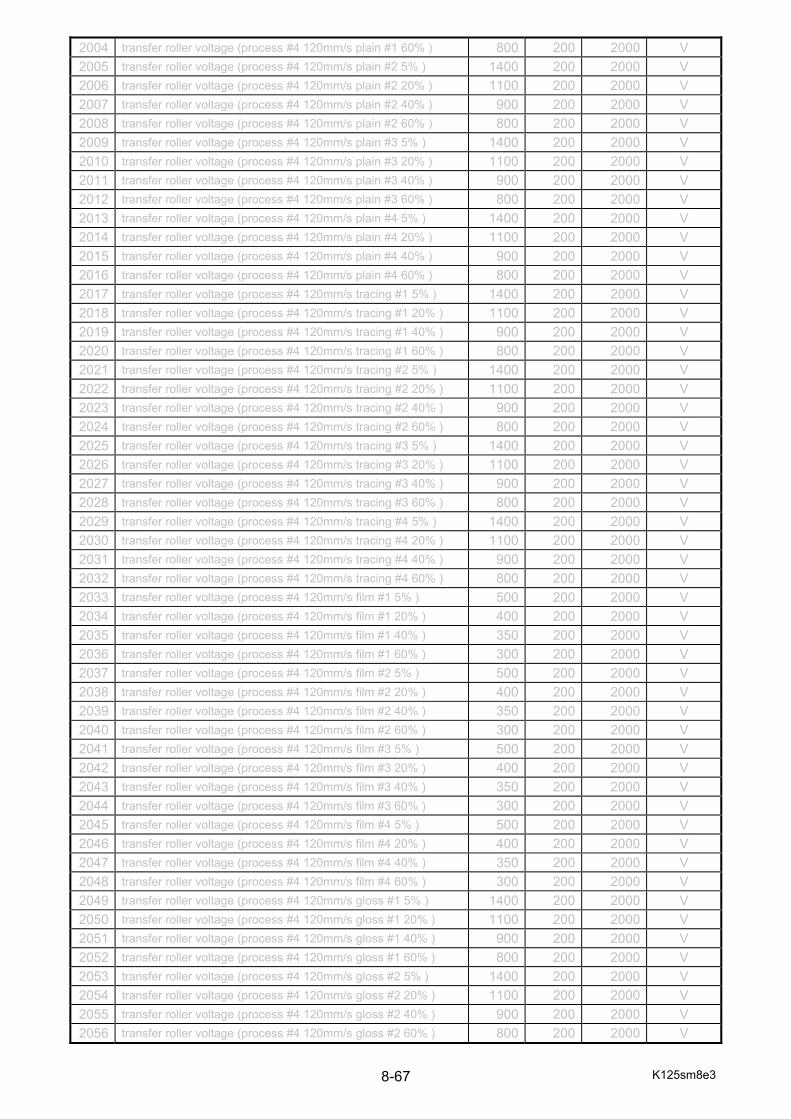
K125sm8e3 8-67
2004 transfer roller voltage (process #4 120mm/s plain #1 60% ) 800 200 2000 V
2005 transfer roller voltage (process #4 120mm/s plain #2 5% ) 1400 200 2000 V
2006 transfer roller voltage (process #4 120mm/s plain #2 20% ) 1100 200 2000 V
2007 transfer roller voltage (process #4 120mm/s plain #2 40% ) 900 200 2000 V
2008 transfer roller voltage (process #4 120mm/s plain #2 60% ) 800 200 2000 V
2009 transfer roller voltage (process #4 120mm/s plain #3 5% ) 1400 200 2000 V
2010 transfer roller voltage (process #4 120mm/s plain #3 20% ) 1100 200 2000 V
2011 transfer roller voltage (process #4 120mm/s plain #3 40% ) 900 200 2000 V
2012 transfer roller voltage (process #4 120mm/s plain #3 60% ) 800 200 2000 V
2013 transfer roller voltage (process #4 120mm/s plain #4 5% ) 1400 200 2000 V
2014 transfer roller voltage (process #4 120mm/s plain #4 20% ) 1100 200 2000 V
2015 transfer roller voltage (process #4 120mm/s plain #4 40% ) 900 200 2000 V
2016 transfer roller voltage (process #4 120mm/s plain #4 60% ) 800 200 2000 V
2017 transfer roller voltage (process #4 120mm/s tracing #1 5% ) 1400 200 2000 V
2018 transfer roller voltage (process #4 120mm/s tracing #1 20% ) 1100 200 2000 V
2019 transfer roller voltage (process #4 120mm/s tracing #1 40% ) 900 200 2000 V
2020 transfer roller voltage (process #4 120mm/s tracing #1 60% ) 800 200 2000 V
2021 transfer roller voltage (process #4 120mm/s tracing #2 5% ) 1400 200 2000 V
2022 transfer roller voltage (process #4 120mm/s tracing #2 20% ) 1100 200 2000 V
2023 transfer roller voltage (process #4 120mm/s tracing #2 40% ) 900 200 2000 V
2024 transfer roller voltage (process #4 120mm/s tracing #2 60% ) 800 200 2000 V
2025 transfer roller voltage (process #4 120mm/s tracing #3 5% ) 1400 200 2000 V
2026 transfer roller voltage (process #4 120mm/s tracing #3 20% ) 1100 200 2000 V
2027 transfer roller voltage (process #4 120mm/s tracing #3 40% ) 900 200 2000 V
2028 transfer roller voltage (process #4 120mm/s tracing #3 60% ) 800 200 2000 V
2029 transfer roller voltage (process #4 120mm/s tracing #4 5% ) 1400 200 2000 V
2030 transfer roller voltage (process #4 120mm/s tracing #4 20% ) 1100 200 2000 V
2031 transfer roller voltage (process #4 120mm/s tracing #4 40% ) 900 200 2000 V
2032 transfer roller voltage (process #4 120mm/s tracing #4 60% ) 800 200 2000 V
2033 transfer roller voltage (process #4 120mm/s film #1 5% ) 500 200 2000 V
2034 transfer roller voltage (process #4 120mm/s film #1 20% ) 400 200 2000 V
2035 transfer roller voltage (process #4 120mm/s film #1 40% ) 350 200 2000 V
2036 transfer roller voltage (process #4 120mm/s film #1 60% ) 300 200 2000 V
2037 transfer roller voltage (process #4 120mm/s film #2 5% ) 500 200 2000 V
2038 transfer roller voltage (process #4 120mm/s film #2 20% ) 400 200 2000 V
2039 transfer roller voltage (process #4 120mm/s film #2 40% ) 350 200 2000 V
2040 transfer roller voltage (process #4 120mm/s film #2 60% ) 300 200 2000 V
2041 transfer roller voltage (process #4 120mm/s film #3 5% ) 500 200 2000 V
2042 transfer roller voltage (process #4 120mm/s film #3 20% ) 400 200 2000 V
2043 transfer roller voltage (process #4 120mm/s film #3 40% ) 350 200 2000 V
2044 transfer roller voltage (process #4 120mm/s film #3 60% ) 300 200 2000 V
2045 transfer roller voltage (process #4 120mm/s film #4 5% ) 500 200 2000 V
2046 transfer roller voltage (process #4 120mm/s film #4 20% ) 400 200 2000 V
2047 transfer roller voltage (process #4 120mm/s film #4 40% ) 350 200 2000 V
2048 transfer roller voltage (process #4 120mm/s film #4 60% ) 300 200 2000 V
2049 transfer roller voltage (process #4 120mm/s gloss #1 5% ) 1400 200 2000 V
2050 transfer roller voltage (process #4 120mm/s gloss #1 20% ) 1100 200 2000 V
2051 transfer roller voltage (process #4 120mm/s gloss #1 40% ) 900 200 2000 V
2052 transfer roller voltage (process #4 120mm/s gloss #1 60% ) 800 200 2000 V
2053 transfer roller voltage (process #4 120mm/s gloss #2 5% ) 1400 200 2000 V
2054 transfer roller voltage (process #4 120mm/s gloss #2 20% ) 1100 200 2000 V
2055 transfer roller voltage (process #4 120mm/s gloss #2 40% ) 900 200 2000 V
2056 transfer roller voltage (process #4 120mm/s gloss #2 60% ) 800 200 2000 V

K125sm8e3 8-68
2057 transfer roller voltage (process #4 120mm/s gloss #3 5% ) 1400 200 2000 V
2058 transfer roller voltage (process #4 120mm/s gloss #3 20% ) 1100 200 2000 V
2059 transfer roller voltage (process #4 120mm/s gloss #3 40% ) 900 200 2000 V
2060 transfer roller voltage (process #4 120mm/s gloss #3 60% ) 800 200 2000 V
2061 transfer roller voltage (process #4 120mm/s gloss #4 5% ) 1400 200 2000 V
2062 transfer roller voltage (process #4 120mm/s gloss #4 20% ) 1100 200 2000 V
2063 transfer roller voltage (process #4 120mm/s gloss #4 40% ) 900 200 2000 V
2064 transfer roller voltage (process #4 120mm/s gloss #4 60% ) 800 200 2000 V
2065 transfer roller voltage (process #4 120mm/s heavy #1 5% ) 1400 200 2000 V
2066 transfer roller voltage (process #4 120mm/s heavy #1 20% ) 1100 200 2000 V
2067 transfer roller voltage (process #4 120mm/s heavy #1 40% ) 900 200 2000 V
2068 transfer roller voltage (process #4 120mm/s heavy #1 60% ) 800 200 2000 V
2069 transfer roller voltage (process #4 120mm/s heavy #2 5% ) 1400 200 2000 V
2070 transfer roller voltage (process #4 120mm/s heavy #2 20% ) 1100 200 2000 V
2071 transfer roller voltage (process #4 120mm/s heavy #2 40% ) 900 200 2000 V
2072 transfer roller voltage (process #4 120mm/s heavy #2 60% ) 800 200 2000 V
2073 transfer roller voltage (process #4 120mm/s heavy #3 5% ) 1400 200 2000 V
2074 transfer roller voltage (process #4 120mm/s heavy #3 20% ) 1100 200 2000 V
2075 transfer roller voltage (process #4 120mm/s heavy #3 40% ) 900 200 2000 V
2076 transfer roller voltage (process #4 120mm/s heavy #3 60% ) 800 200 2000 V
2077 transfer roller voltage (process #4 120mm/s heavy #4 5% ) 1400 200 2000 V
2078 transfer roller voltage (process #4 120mm/s heavy #4 20% ) 1100 200 2000 V
2079 transfer roller voltage (process #4 120mm/s heavy #4 40% ) 900 200 2000 V
2080 transfer roller voltage (process #4 120mm/s heavy #4 60% ) 800 200 2000 V
2081 media charge roller bias (60mm/s plain #1 5%) 1200 200 2000 V
2082 media charge roller bias (60mm/s plain #1 20%) 1200 200 2000 V
2083 media charge roller bias (60mm/s plain #1 40%) 1200 200 2000 V
2084 media charge roller bias (60mm/s plain #1 60%) 1200 200 2000 V
2085 media charge roller bias (60mm/s plain #2 5%) 1200 200 2000 V
2086 media charge roller bias (60mm/s plain #2 20%) 1200 200 2000 V
2087 media charge roller bias (60mm/s plain #2 40%) 1200 200 2000 V
2088 media charge roller bias (60mm/s plain #2 60%) 1200 200 2000 V
2089 media charge roller bias (60mm/s plain #3 5%) 1200 200 2000 V
2090 media charge roller bias (60mm/s plain #3 20%) 1200 200 2000 V
2091 media charge roller bias (60mm/s plain #3 40%) 1200 200 2000 V
2092 media charge roller bias (60mm/s plain #3 60%) 1200 200 2000 V
2093 media charge roller bias (60mm/s plain #4 5%) 1200 200 2000 V
2094 media charge roller bias (60mm/s plain #4 20%) 1200 200 2000 V
2095 media charge roller bias (60mm/s plain #4 40%) 1200 200 2000 V
2096 media charge roller bias (60mm/s plain #4 60%) 1200 200 2000 V
2097 media charge roller bias (60mm/s tracing #1 5%) 1200 200 2000 V
2098 media charge roller bias (60mm/s tracing #1 20%) 1200 200 2000 V
2099 media charge roller bias (60mm/s tracing #1 40%) 1200 200 2000 V
2100 media charge roller bias (60mm/s tracing #1 60%) 1200 200 2000 V
2101 media charge roller bias (60mm/s tracing #2 5%) 1200 200 2000 V
2102 media charge roller bias (60mm/s tracing #2 20%) 1200 200 2000 V
2103 media charge roller bias (60mm/s tracing #2 40%) 1200 200 2000 V
2104 media charge roller bias (60mm/s tracing #2 60%) 1200 200 2000 V
2105 media charge roller bias (60mm/s tracing #3 5%) 1200 200 2000 V
2106 media charge roller bias (60mm/s tracing #3 20%) 1200 200 2000 V
2107 media charge roller bias (60mm/s tracing #3 40%) 1200 200 2000 V
2108 media charge roller bias (60mm/s tracing #3 60%) 1200 200 2000 V
2109 media charge roller bias (60mm/s tracing #4 5%) 1200 200 2000 V
K125sm8e3 8-69
2110 media charge roller bias (60mm/s tracing #4 20%) 1200 200 2000 V
2111 media charge roller bias (60mm/s tracing #4 40%) 1200 200 2000 V
2112 media charge roller bias (60mm/s tracing #4 60%) 1200 200 2000 V
2113 media charge roller bias (60mm/s film #1 5%) 1200 200 2000 V
2114 media charge roller bias (60mm/s film #1 20%) 1200 200 2000 V
2115 media charge roller bias (60mm/s film #1 40%) 1200 200 2000 V
2116 media charge roller bias (60mm/s film #1 60%) 1200 200 2000 V
2117 media charge roller bias (60mm/s film #2 5%) 1200 200 2000 V
2118 media charge roller bias (60mm/s film #2 20%) 1200 200 2000 V
2119 media charge roller bias (60mm/s film #2 40%) 1200 200 2000 V
2120 media charge roller bias (60mm/s film #2 60%) 1200 200 2000 V
2121 media charge roller bias (60mm/s film #3 5%) 1200 200 2000 V
2122 media charge roller bias (60mm/s film #3 20%) 1200 200 2000 V
2123 media charge roller bias (60mm/s film #3 40%) 1200 200 2000 V
2124 media charge roller bias (60mm/s film #3 60%) 1200 200 2000 V
2125 media charge roller bias (60mm/s film #4 5%) 1200 200 2000 V
2126 media charge roller bias (60mm/s film #4 20%) 1200 200 2000 V
2127 media charge roller bias (60mm/s film #4 40%) 1200 200 2000 V
2128 media charge roller bias (60mm/s film #4 60%) 1200 200 2000 V
2129 media charge roller bias (60mm/s gloss #1 5%) 1200 200 2000 V
2130 media charge roller bias (60mm/s gloss #1 20%) 1200 200 2000 V
2131 media charge roller bias (60mm/s gloss #1 40%) 1200 200 2000 V
2132 media charge roller bias (60mm/s gloss #1 60%) 1200 200 2000 V
2133 media charge roller bias (60mm/s gloss #2 5%) 1200 200 2000 V
2134 media charge roller bias (60mm/s gloss #2 20%) 1200 200 2000 V
2135 media charge roller bias (60mm/s gloss #2 40%) 1200 200 2000 V
2136 media charge roller bias (60mm/s gloss #2 60%) 1200 200 2000 V
2137 media charge roller bias (60mm/s gloss #3 5%) 1200 200 2000 V
2138 media charge roller bias (60mm/s gloss #3 20%) 1200 200 2000 V
2139 media charge roller bias (60mm/s gloss #3 40%) 1200 200 2000 V
2140 media charge roller bias (60mm/s gloss #3 60%) 1200 200 2000 V
2141 media charge roller bias (60mm/s gloss #4 5%) 1200 200 2000 V
2142 media charge roller bias (60mm/s gloss #4 20%) 1200 200 2000 V
2143 media charge roller bias (60mm/s gloss #4 40%) 1200 200 2000 V
2144 media charge roller bias (60mm/s gloss #4 60%) 1200 200 2000 V
2145 media charge roller bias (60mm/s heavy #1 5%) 1200 200 2000 V
2146 media charge roller bias (60mm/s heavy #1 20%) 1200 200 2000 V
2147 media charge roller bias (60mm/s heavy #1 40%) 1200 200 2000 V
2148 media charge roller bias (60mm/s heavy #1 60%) 1200 200 2000 V
2149 media charge roller bias (60mm/s heavy #2 5%) 1200 200 2000 V
2150 media charge roller bias (60mm/s heavy #2 20%) 1200 200 2000 V
2151 media charge roller bias (60mm/s heavy #2 40%) 1200 200 2000 V
2152 media charge roller bias (60mm/s heavy #2 60%) 1200 200 2000 V
2153 media charge roller bias (60mm/s heavy #3 5%) 1200 200 2000 V
2154 media charge roller bias (60mm/s heavy #3 20%) 1200 200 2000 V
2155 media charge roller bias (60mm/s heavy #3 40%) 1200 200 2000 V
2156 media charge roller bias (60mm/s heavy #3 60%) 1200 200 2000 V
2157 media charge roller bias (60mm/s heavy #4 5%) 1200 200 2000 V
2158 media charge roller bias (60mm/s heavy #4 20%) 1200 200 2000 V
2159 media charge roller bias (60mm/s heavy #4 40%) 1200 200 2000 V
2160 media charge roller bias (60mm/s heavy #4 60%) 1200 200 2000 V
2161 media charge roller bias (100mm/s plain #1 5%) 1200 200 2000 V
2162 media charge roller bias (100mm/s plain #1 20%) 1200 200 2000 V
K125sm8e3 8-70
2163 media charge roller bias (100mm/s plain #1 40%) 1200 200 2000 V
2164 media charge roller bias (100mm/s plain #1 60%) 1200 200 2000 V
2165 media charge roller bias (100mm/s plain #2 5%) 1200 200 2000 V
2166 media charge roller bias (100mm/s plain #2 20%) 1200 200 2000 V
2167 media charge roller bias (100mm/s plain #2 40%) 1200 200 2000 V
2168 media charge roller bias (100mm/s plain #2 60%) 1200 200 2000 V
2169 media charge roller bias (100mm/s plain #3 5%) 1200 200 2000 V
2170 media charge roller bias (100mm/s plain #3 20%) 1200 200 2000 V
2171 media charge roller bias (100mm/s plain #3 40%) 1200 200 2000 V
2172 media charge roller bias (100mm/s plain #3 60%) 1200 200 2000 V
2173 media charge roller bias (100mm/s plain #4 5%) 1200 200 2000 V
2174 media charge roller bias (100mm/s plain #4 20%) 1200 200 2000 V
2175 media charge roller bias (100mm/s plain #4 40%) 1200 200 2000 V
2176 media charge roller bias (100mm/s plain #4 60%) 1200 200 2000 V
2177 media charge roller bias (100mm/s tracing #1 5%) 1200 200 2000 V
2178 media charge roller bias (100mm/s tracing #1 20%) 1200 200 2000 V
2179 media charge roller bias (100mm/s tracing #1 40%) 1200 200 2000 V
2180 media charge roller bias (100mm/s tracing #1 60%) 1200 200 2000 V
2181 media charge roller bias (100mm/s tracing #2 5%) 1200 200 2000 V
2182 media charge roller bias (100mm/s tracing #2 20%) 1200 200 2000 V
2183 media charge roller bias (100mm/s tracing #2 40%) 1200 200 2000 V
2184 media charge roller bias (100mm/s tracing #2 60%) 1200 200 2000 V
2185 media charge roller bias (100mm/s tracing #3 5%) 1200 200 2000 V
2186 media charge roller bias (100mm/s tracing #3 20%) 1200 200 2000 V
2187 media charge roller bias (100mm/s tracing #3 40%) 1200 200 2000 V
2188 media charge roller bias (100mm/s tracing #3 60%) 1200 200 2000 V
2189 media charge roller bias (100mm/s tracing #4 5%) 1200 200 2000 V
2190 media charge roller bias (100mm/s tracing #4 20%) 1200 200 2000 V
2191 media charge roller bias (100mm/s tracing #4 40%) 1200 200 2000 V
2192 media charge roller bias (100mm/s tracing #4 60%) 1200 200 2000 V
2193 media charge roller bias (100mm/s film #1 5%) 1200 200 2000 V
2194 media charge roller bias (100mm/s film #1 20%) 1200 200 2000 V
2195 media charge roller bias (100mm/s film #1 40%) 1200 200 2000 V
2196 media charge roller bias (100mm/s film #1 60%) 1200 200 2000 V
2197 media charge roller bias (100mm/s film #2 5%) 1200 200 2000 V
2198 media charge roller bias (100mm/s film #2 20%) 1200 200 2000 V
2199 media charge roller bias (100mm/s film #2 40%) 1200 200 2000 V
2200 media charge roller bias (100mm/s film #2 60%) 1200 200 2000 V
2201 media charge roller bias (100mm/s film #3 5%) 1200 200 2000 V
2202 media charge roller bias (100mm/s film #3 20%) 1200 200 2000 V
2203 media charge roller bias (100mm/s film #3 40%) 1200 200 2000 V
2204 media charge roller bias (100mm/s film #3 60%) 1200 200 2000 V
2205 media charge roller bias (100mm/s film #4 5%) 1200 200 2000 V
2206 media charge roller bias (100mm/s film #4 20%) 1200 200 2000 V
2207 media charge roller bias (100mm/s film #4 40%) 1200 200 2000 V
2208 media charge roller bias (100mm/s film #4 60%) 1200 200 2000 V
2209 media charge roller bias (100mm/s gloss #1 5%) 1200 200 2000 V
2210 media charge roller bias (100mm/s gloss #1 20%) 1200 200 2000 V
2211 media charge roller bias (100mm/s gloss #1 40%) 1200 200 2000 V
2212 media charge roller bias (100mm/s gloss #1 60%) 1200 200 2000 V
2213 media charge roller bias (100mm/s gloss #2 5%) 1200 200 2000 V
2214 media charge roller bias (100mm/s gloss #2 20%) 1200 200 2000 V
2215 media charge roller bias (100mm/s gloss #2 40%) 1200 200 2000 V
K125sm8e3 8-71
2216 media charge roller bias (100mm/s gloss #2 60%) 1200 200 2000 V
2217 media charge roller bias (100mm/s gloss #3 5%) 1200 200 2000 V
2218 media charge roller bias (100mm/s gloss #3 20%) 1200 200 2000 V
2219 media charge roller bias (100mm/s gloss #3 40%) 1200 200 2000 V
2220 media charge roller bias (100mm/s gloss #3 60%) 1200 200 2000 V
2221 media charge roller bias (100mm/s gloss #4 5%) 1200 200 2000 V
2222 media charge roller bias (100mm/s gloss #4 20%) 1200 200 2000 V
2223 media charge roller bias (100mm/s gloss #4 40%) 1200 200 2000 V
2224 media charge roller bias (100mm/s gloss #4 60%) 1200 200 2000 V
2225 media charge roller bias (100mm/s heavy #1 5%) 1200 200 2000 V
2226 media charge roller bias (100mm/s heavy #1 20%) 1200 200 2000 V
2227 media charge roller bias (100mm/s heavy #1 40%) 1200 200 2000 V
2228 media charge roller bias (100mm/s heavy #1 60%) 1200 200 2000 V
2229 media charge roller bias (100mm/s heavy #2 5%) 1200 200 2000 V
2230 media charge roller bias (100mm/s heavy #2 20%) 1200 200 2000 V
2231 media charge roller bias (100mm/s heavy #2 40%) 1200 200 2000 V
2232 media charge roller bias (100mm/s heavy #2 60%) 1200 200 2000 V
2233 media charge roller bias (100mm/s heavy #3 5%) 1200 200 2000 V
2234 media charge roller bias (100mm/s heavy #3 20%) 1200 200 2000 V
2235 media charge roller bias (100mm/s heavy #3 40%) 1200 200 2000 V
2236 media charge roller bias (100mm/s heavy #3 60%) 1200 200 2000 V
2237 media charge roller bias (100mm/s heavy #4 5%) 1200 200 2000 V
2238 media charge roller bias (100mm/s heavy #4 20%) 1200 200 2000 V
2239 media charge roller bias (100mm/s heavy #4 40%) 1200 200 2000 V
2240 media charge roller bias (100mm/s heavy #4 60%) 1200 200 2000 V
2241 media charge roller bias (120mm/s plain #1 5%) 1200 200 2000 V
2242 media charge roller bias (120mm/s plain #1 20%) 1200 200 2000 V
2243 media charge roller bias (120mm/s plain #1 40%) 1200 200 2000 V
2244 media charge roller bias (120mm/s plain #1 60%) 1200 200 2000 V
2245 media charge roller bias (120mm/s plain #2 5%) 1200 200 2000 V
2246 media charge roller bias (120mm/s plain #2 20%) 1200 200 2000 V
2247 media charge roller bias (120mm/s plain #2 40%) 1200 200 2000 V
2248 media charge roller bias (120mm/s plain #2 60%) 1200 200 2000 V
2249 media charge roller bias (120mm/s plain #3 5%) 1200 200 2000 V
2250 media charge roller bias (120mm/s plain #3 20%) 1200 200 2000 V
2251 media charge roller bias (120mm/s plain #3 40%) 1200 200 2000 V
2252 media charge roller bias (120mm/s plain #3 60%) 1200 200 2000 V
2253 media charge roller bias (120mm/s plain #4 5%) 1200 200 2000 V
2254 media charge roller bias (120mm/s plain #4 20%) 1200 200 2000 V
2255 media charge roller bias (120mm/s plain #4 40%) 1200 200 2000 V
2256 media charge roller bias (120mm/s plain #4 60%) 1200 200 2000 V
2257 media charge roller bias (120mm/s tracing #1 5%) 1200 200 2000 V
2258 media charge roller bias (120mm/s tracing #1 20%) 1200 200 2000 V
2259 media charge roller bias (120mm/s tracing #1 40%) 1200 200 2000 V
2260 media charge roller bias (120mm/s tracing #1 60%) 1200 200 2000 V
2261 media charge roller bias (120mm/s tracing #2 5%) 1200 200 2000 V
2262 media charge roller bias (120mm/s tracing #2 20%) 1200 200 2000 V
2263 media charge roller bias (120mm/s tracing #2 40%) 1200 200 2000 V
2264 media charge roller bias (120mm/s tracing #2 60%) 1200 200 2000 V
2265 media charge roller bias (120mm/s tracing #3 5%) 1200 200 2000 V
2266 media charge roller bias (120mm/s tracing #3 20%) 1200 200 2000 V
2267 media charge roller bias (120mm/s tracing #3 40%) 1200 200 2000 V
2268 media charge roller bias (120mm/s tracing #3 60%) 1200 200 2000 V
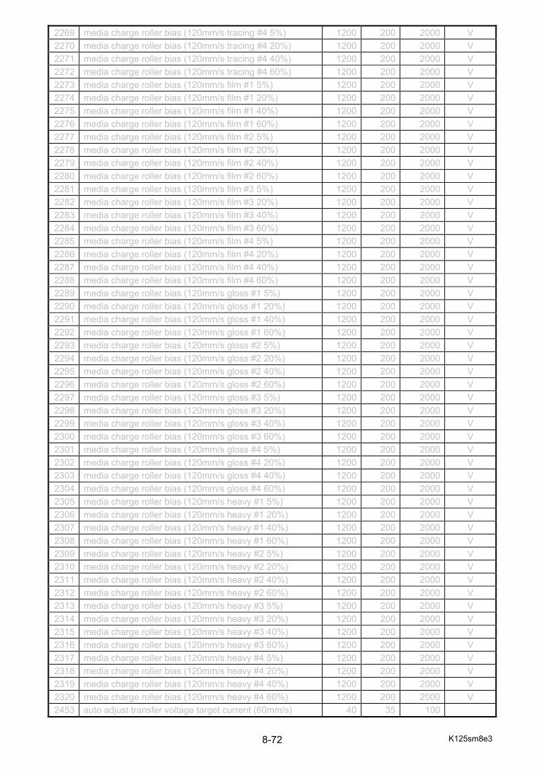
K125sm8e3 8-72
2269 media charge roller bias (120mm/s tracing #4 5%) 1200 200 2000 V
2270 media charge roller bias (120mm/s tracing #4 20%) 1200 200 2000 V
2271 media charge roller bias (120mm/s tracing #4 40%) 1200 200 2000 V
2272 media charge roller bias (120mm/s tracing #4 60%) 1200 200 2000 V
2273 media charge roller bias (120mm/s film #1 5%) 1200 200 2000 V
2274 media charge roller bias (120mm/s film #1 20%) 1200 200 2000 V
2275 media charge roller bias (120mm/s film #1 40%) 1200 200 2000 V
2276 media charge roller bias (120mm/s film #1 60%) 1200 200 2000 V
2277 media charge roller bias (120mm/s film #2 5%) 1200 200 2000 V
2278 media charge roller bias (120mm/s film #2 20%) 1200 200 2000 V
2279 media charge roller bias (120mm/s film #2 40%) 1200 200 2000 V
2280 media charge roller bias (120mm/s film #2 60%) 1200 200 2000 V
2281 media charge roller bias (120mm/s film #3 5%) 1200 200 2000 V
2282 media charge roller bias (120mm/s film #3 20%) 1200 200 2000 V
2283 media charge roller bias (120mm/s film #3 40%) 1200 200 2000 V
2284 media charge roller bias (120mm/s film #3 60%) 1200 200 2000 V
2285 media charge roller bias (120mm/s film #4 5%) 1200 200 2000 V
2286 media charge roller bias (120mm/s film #4 20%) 1200 200 2000 V
2287 media charge roller bias (120mm/s film #4 40%) 1200 200 2000 V
2288 media charge roller bias (120mm/s film #4 60%) 1200 200 2000 V
2289 media charge roller bias (120mm/s gloss #1 5%) 1200 200 2000 V
2290 media charge roller bias (120mm/s gloss #1 20%) 1200 200 2000 V
2291 media charge roller bias (120mm/s gloss #1 40%) 1200 200 2000 V
2292 media charge roller bias (120mm/s gloss #1 60%) 1200 200 2000 V
2293 media charge roller bias (120mm/s gloss #2 5%) 1200 200 2000 V
2294 media charge roller bias (120mm/s gloss #2 20%) 1200 200 2000 V
2295 media charge roller bias (120mm/s gloss #2 40%) 1200 200 2000 V
2296 media charge roller bias (120mm/s gloss #2 60%) 1200 200 2000 V
2297 media charge roller bias (120mm/s gloss #3 5%) 1200 200 2000 V
2298 media charge roller bias (120mm/s gloss #3 20%) 1200 200 2000 V
2299 media charge roller bias (120mm/s gloss #3 40%) 1200 200 2000 V
2300 media charge roller bias (120mm/s gloss #3 60%) 1200 200 2000 V
2301 media charge roller bias (120mm/s gloss #4 5%) 1200 200 2000 V
2302 media charge roller bias (120mm/s gloss #4 20%) 1200 200 2000 V
2303 media charge roller bias (120mm/s gloss #4 40%) 1200 200 2000 V
2304 media charge roller bias (120mm/s gloss #4 60%) 1200 200 2000 V
2305 media charge roller bias (120mm/s heavy #1 5%) 1200 200 2000 V
2306 media charge roller bias (120mm/s heavy #1 20%) 1200 200 2000 V
2307 media charge roller bias (120mm/s heavy #1 40%) 1200 200 2000 V
2308 media charge roller bias (120mm/s heavy #1 60%) 1200 200 2000 V
2309 media charge roller bias (120mm/s heavy #2 5%) 1200 200 2000 V
2310 media charge roller bias (120mm/s heavy #2 20%) 1200 200 2000 V
2311 media charge roller bias (120mm/s heavy #2 40%) 1200 200 2000 V
2312 media charge roller bias (120mm/s heavy #2 60%) 1200 200 2000 V
2313 media charge roller bias (120mm/s heavy #3 5%) 1200 200 2000 V
2314 media charge roller bias (120mm/s heavy #3 20%) 1200 200 2000 V
2315 media charge roller bias (120mm/s heavy #3 40%) 1200 200 2000 V
2316 media charge roller bias (120mm/s heavy #3 60%) 1200 200 2000 V
2317 media charge roller bias (120mm/s heavy #4 5%) 1200 200 2000 V
2318 media charge roller bias (120mm/s heavy #4 20%) 1200 200 2000 V
2319 media charge roller bias (120mm/s heavy #4 40%) 1200 200 2000 V
2320 media charge roller bias (120mm/s heavy #4 60%) 1200 200 2000 V
2453 auto adjust transfer voltage target current (60mm/s) 40 35 100

K125sm8e3 8-73
2454 auto adjust transfer voltage target current (100mm/s) 70 35 100
2455 auto adjust transfer voltage target current (120mm/s) 85 35 100
2468 transfer roller voltage offset (process #1 60mm/s large) 200 0 500 V 2469 transfer roller voltage offset (process #1 60mm/s middle) 200 0 500 V 2470 transfer roller voltage offset (process #1 60mm/s small) 200 0 500 V 2471 transfer roller voltage offset (process #1 100mm/s large) 300 0 500 V 2472 transfer roller voltage offset (process #1 100mm/s middle) 300 0 500 V 2473 transfer roller voltage offset (process #1 100mm/s small) 300 0 500 V 2474 transfer roller voltage offset (process #1 120mm/s large) 300 0 500 V 2475 transfer roller voltage offset (process #1 120mm/s middle) 300 0 500 V 2476 transfer roller voltage offset (process #1 120mm/s small) 300 0 500 V 2477 transfer roller voltage offset (process #2 60mm/s large) 200 0 500 V 2478 transfer roller voltage offset (process #2 60mm/s middle) 200 0 500 V 2479 transfer roller voltage offset (process #2 60mm/s small) 200 0 500 V 2480 transfer roller voltage offset (process #2 100mm/s large) 300 0 500 V 2481 transfer roller voltage offset (process #2 100mm/s middle) 300 0 500 V 2482 transfer roller voltage offset (process #2 100mm/s small) 300 0 500 V 2483 transfer roller voltage offset (process #2 120mm/s large) 300 0 500 V 2484 transfer roller voltage offset (process #2 120mm/s middle) 300 0 500 V 2485 transfer roller voltage offset (process #2 120mm/s small) 300 0 500 V 2486 transfer roller voltage offset (process #3 60mm/s large) 200 0 500 V 2487 transfer roller voltage offset (process #3 60mm/s middle) 200 0 500 V 2488 transfer roller voltage offset (process #3 60mm/s small) 200 0 500 V 2489 transfer roller voltage offset (process #3 100mm/s large) 300 0 500 V 2490 transfer roller voltage offset (process #3 100mm/s middle) 300 0 500 V 2491 transfer roller voltage offset (process #3 100mm/s small) 300 0 500 V 2492 transfer roller voltage offset (process #3 120mm/s large) 300 0 500 V 2493 transfer roller voltage offset (process #3 120mm/s middle) 300 0 500 V 2494 transfer roller voltage offset (process #3 120mm/s small) 300 0 500 V 2495 transfer roller voltage offset (process #4 60mm/s large) 200 0 500 V 2496 transfer roller voltage offset (process #4 60mm/s middle) 200 0 500 V 2497 transfer roller voltage offset (process #4 60mm/s small) 200 0 500 V 2498 transfer roller voltage offset (process #4 100mm/s large) 300 0 500 V 2499 transfer roller voltage offset (process #4 100mm/s middle) 300 0 500 V 2500 transfer roller voltage offset (process #4 100mm/s small) 300 0 500 V 2501 transfer roller voltage offset (process #4 120mm/s large) 300 0 500 V 2502 transfer roller voltage offset (process #4 120mm/s middle) 300 0 500 V 2503 transfer roller voltage offset (process #4 120mm/s small) 300 0 500 V
image enhance 1401 image enhance table #1 1-a 5 0 15 - 1402 image enhance table #1 2-a 5 0 15 - 1403 image enhance table #1 3-a 5 0 15 - 1404 image enhance table #1 4-a 5 0 15 - 1405 image enhance table #1 5-a 5 0 15 - 1406 image enhance table #1 1-b 2 0 15 - 1407 image enhance table #1 2-b 2 0 15 - 1408 image enhance table #1 3-b 2 0 15 - 1409 image enhance table #1 4-b 2 0 15 - 1410 image enhance table #1 5-b 2 0 15 - 1411 image enhance table #2 1-a 5 0 15 - 1412 image enhance table #2 2-a 6 0 15 - 1413 image enhance table #2 3-a 10 0 15 - 1414 image enhance table #2 4-a 13 0 15 -
K125sm8e3 8-74
1415 image enhance table #2 5-a 15 0 15 - 1416 image enhance table #2 1-b 2 0 15 - 1417 image enhance table #2 2-b 5 0 15 - 1418 image enhance table #2 3-b 6 0 15 - 1419 image enhance table #2 4-b 10 0 15 - 1420 image enhance table #2 5-b 13 0 15 - 1421 image enhance table #3 1-a 5 0 15 - 1422 image enhance table #3 2-a 6 0 15 - 1423 image enhance table #3 3-a 10 0 15 - 1424 image enhance table #3 4-a 13 0 15 - 1425 image enhance table #3 5-a 15 0 15 - 1426 image enhance table #3 1-b 2 0 15 - 1427 image enhance table #3 2-b 5 0 15 - 1428 image enhance table #3 3-b 6 0 15 - 1429 image enhance table #3 4-b 10 0 15 - 1430 image enhance table #3 5-b 13 0 15 - 1431 image enhance table #4 1-a 5 0 15 - 1432 image enhance table #4 2-a 6 0 15 - 1433 image enhance table #4 3-a 6 0 15 - 1434 image enhance table #4 4-a 6 0 15 - 1435 image enhance table #4 5-a 6 0 15 - 1436 image enhance table #4 1-b 2 0 15 - 1437 image enhance table #4 2-b 5 0 15 - 1438 image enhance table #4 3-b 5 0 15 - 1439 image enhance table #4 4-b 5 0 15 - 1440 image enhance table #4 5-b 5 0 15 - 1441 image enhance table #5 1-a 5 0 15 - 1442 image enhance table #5 2-a 6 0 15 - 1443 image enhance table #5 3-a 10 0 15 - 1444 image enhance table #5 4-a 13 0 15 - 1445 image enhance table #5 5-a 15 0 15 - 1446 image enhance table #5 1-b 2 0 15 - 1447 image enhance table #5 2-b 5 0 15 - 1448 image enhance table #5 3-b 6 0 15 - 1449 image enhance table #5 4-b 10 0 15 - 1450 image enhance table #5 5-b 13 0 15 - 1451 image enhance table #6 1-a 5 0 15 - 1452 image enhance table #6 2-a 6 0 15 - 1453 image enhance table #6 3-a 10 0 15 - 1454 image enhance table #6 4-a 13 0 15 - 1455 image enhance table #6 5-a 15 0 15 - 1456 image enhance table #6 1-b 2 0 15 - 1457 image enhance table #6 2-b 5 0 15 - 1458 image enhance table #6 3-b 6 0 15 - 1459 image enhance table #6 4-b 10 0 15 - 1460 image enhance table #6 5-b 13 0 15 - 1461 image enhance table #7 1-a 5 0 15 - 1462 image enhance table #7 2-a 6 0 15 - 1463 image enhance table #7 3-a 10 0 15 - 1464 image enhance table #7 4-a 13 0 15 - 1465 image enhance table #7 5-a 15 0 15 - 1466 image enhance table #7 1-b 2 0 15 - 1467 image enhance table #7 2-b 5 0 15 -
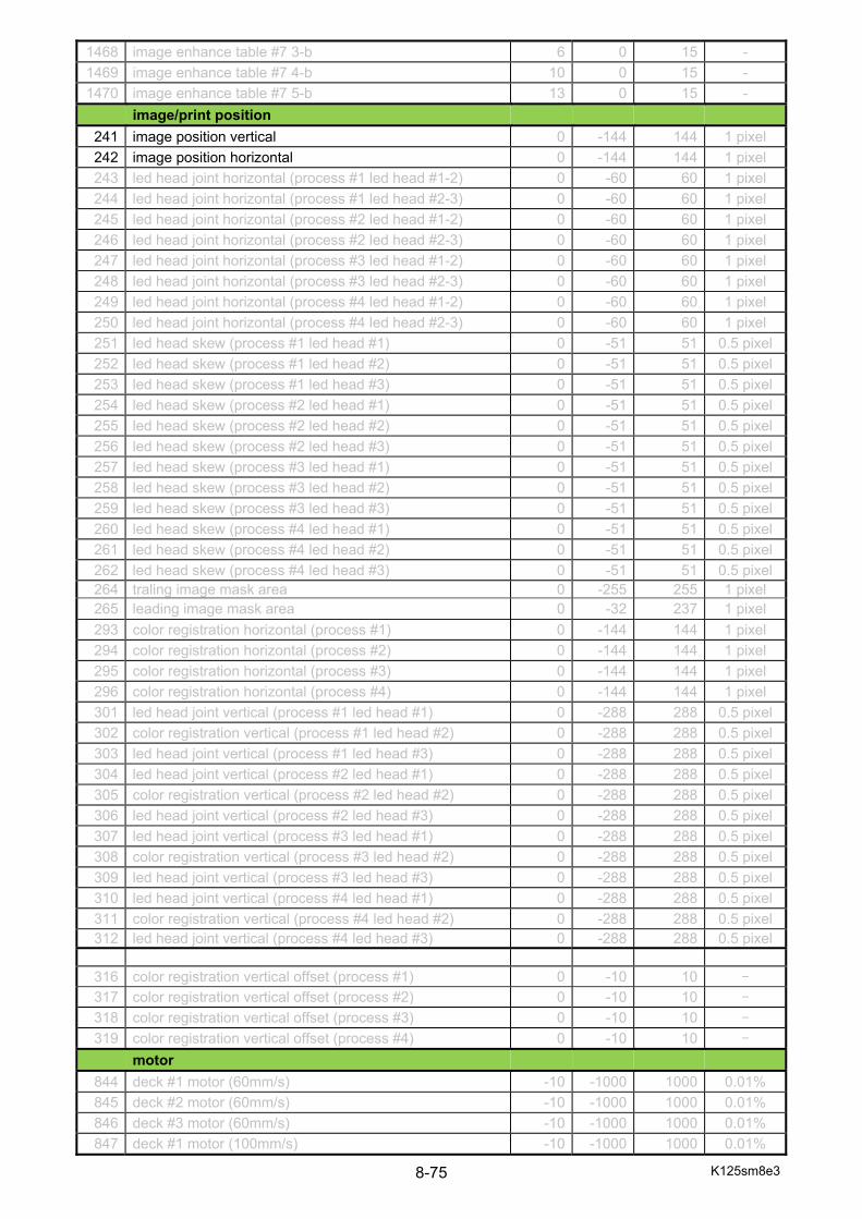
K125sm8e3 8-75
1468 image enhance table #7 3-b 6 0 15 - 1469 image enhance table #7 4-b 10 0 15 - 1470 image enhance table #7 5-b 13 0 15 -
image/print position 241 image position vertical 0 -144 144 1 pixel 242 image position horizontal 0 -144 144 1 pixel 243 led head joint horizontal (process #1 led head #1-2) 0 -60 60 1 pixel 244 led head joint horizontal (process #1 led head #2-3) 0 -60 60 1 pixel 245 led head joint horizontal (process #2 led head #1-2) 0 -60 60 1 pixel 246 led head joint horizontal (process #2 led head #2-3) 0 -60 60 1 pixel 247 led head joint horizontal (process #3 led head #1-2) 0 -60 60 1 pixel 248 led head joint horizontal (process #3 led head #2-3) 0 -60 60 1 pixel 249 led head joint horizontal (process #4 led head #1-2) 0 -60 60 1 pixel 250 led head joint horizontal (process #4 led head #2-3) 0 -60 60 1 pixel 251 led head skew (process #1 led head #1) 0 -51 51 0.5 pixel252 led head skew (process #1 led head #2) 0 -51 51 0.5 pixel253 led head skew (process #1 led head #3) 0 -51 51 0.5 pixel254 led head skew (process #2 led head #1) 0 -51 51 0.5 pixel255 led head skew (process #2 led head #2) 0 -51 51 0.5 pixel256 led head skew (process #2 led head #3) 0 -51 51 0.5 pixel257 led head skew (process #3 led head #1) 0 -51 51 0.5 pixel258 led head skew (process #3 led head #2) 0 -51 51 0.5 pixel259 led head skew (process #3 led head #3) 0 -51 51 0.5 pixel260 led head skew (process #4 led head #1) 0 -51 51 0.5 pixel261 led head skew (process #4 led head #2) 0 -51 51 0.5 pixel262 led head skew (process #4 led head #3) 0 -51 51 0.5 pixel264 traling image mask area 0 -255 255 1 pixel 265 leading image mask area 0 -32 237 1 pixel 293 color registration horizontal (process #1) 0 -144 144 1 pixel 294 color registration horizontal (process #2) 0 -144 144 1 pixel 295 color registration horizontal (process #3) 0 -144 144 1 pixel 296 color registration horizontal (process #4) 0 -144 144 1 pixel 301 led head joint vertical (process #1 led head #1) 0 -288 288 0.5 pixel302 color registration vertical (process #1 led head #2) 0 -288 288 0.5 pixel303 led head joint vertical (process #1 led head #3) 0 -288 288 0.5 pixel304 led head joint vertical (process #2 led head #1) 0 -288 288 0.5 pixel305 color registration vertical (process #2 led head #2) 0 -288 288 0.5 pixel306 led head joint vertical (process #2 led head #3) 0 -288 288 0.5 pixel307 led head joint vertical (process #3 led head #1) 0 -288 288 0.5 pixel308 color registration vertical (process #3 led head #2) 0 -288 288 0.5 pixel309 led head joint vertical (process #3 led head #3) 0 -288 288 0.5 pixel310 led head joint vertical (process #4 led head #1) 0 -288 288 0.5 pixel311 color registration vertical (process #4 led head #2) 0 -288 288 0.5 pixel312 led head joint vertical (process #4 led head #3) 0 -288 288 0.5 pixel
316 color registration vertical offset (process #1) 0 -10 10 -
317 color registration vertical offset (process #2) 0 -10 10 -
318 color registration vertical offset (process #3) 0 -10 10 -
319 color registration vertical offset (process #4) 0 -10 10 -
motor 844 deck #1 motor (60mm/s) -10 -1000 1000 0.01% 845 deck #2 motor (60mm/s) -10 -1000 1000 0.01% 846 deck #3 motor (60mm/s) -10 -1000 1000 0.01% 847 deck #1 motor (100mm/s) -10 -1000 1000 0.01%
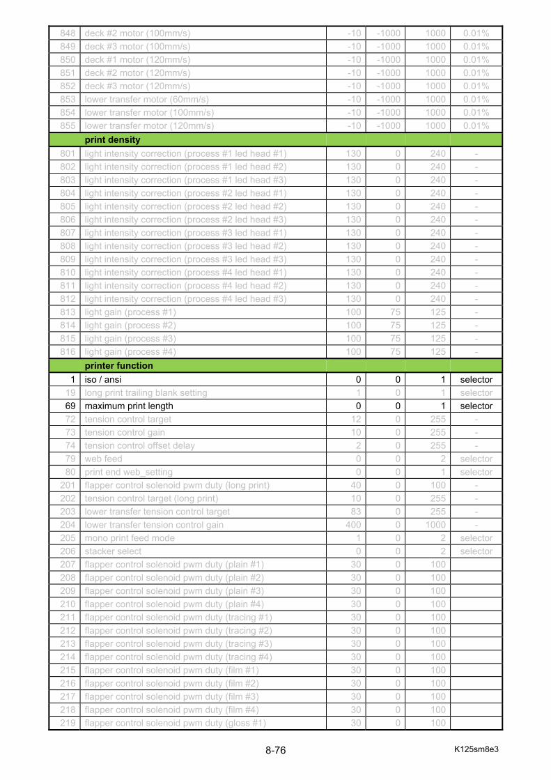
K125sm8e3 8-76
848 deck #2 motor (100mm/s) -10 -1000 1000 0.01% 849 deck #3 motor (100mm/s) -10 -1000 1000 0.01% 850 deck #1 motor (120mm/s) -10 -1000 1000 0.01% 851 deck #2 motor (120mm/s) -10 -1000 1000 0.01% 852 deck #3 motor (120mm/s) -10 -1000 1000 0.01% 853 lower transfer motor (60mm/s) -10 -1000 1000 0.01% 854 lower transfer motor (100mm/s) -10 -1000 1000 0.01% 855 lower transfer motor (120mm/s) -10 -1000 1000 0.01%
print density 801 light intensity correction (process #1 led head #1) 130 0 240 - 802 light intensity correction (process #1 led head #2) 130 0 240 - 803 light intensity correction (process #1 led head #3) 130 0 240 - 804 light intensity correction (process #2 led head #1) 130 0 240 - 805 light intensity correction (process #2 led head #2) 130 0 240 - 806 light intensity correction (process #2 led head #3) 130 0 240 - 807 light intensity correction (process #3 led head #1) 130 0 240 - 808 light intensity correction (process #3 led head #2) 130 0 240 - 809 light intensity correction (process #3 led head #3) 130 0 240 - 810 light intensity correction (process #4 led head #1) 130 0 240 - 811 light intensity correction (process #4 led head #2) 130 0 240 - 812 light intensity correction (process #4 led head #3) 130 0 240 - 813 light gain (process #1) 100 75 125 - 814 light gain (process #2) 100 75 125 - 815 light gain (process #3) 100 75 125 - 816 light gain (process #4) 100 75 125 -
printer function 1 iso / ansi 0 0 1 selector
19 long print trailing blank setting 1 0 1 selector 69 maximum print length 0 0 1 selector 72 tension control target 12 0 255 - 73 tension control gain 10 0 255 - 74 tension control offset delay 2 0 255 - 79 web feed 0 0 2 selector 80 print end web_setting 0 0 1 selector
201 flapper control solenoid pwm duty (long print) 40 0 100 - 202 tension control target (long print) 10 0 255 - 203 lower transfer tension control target 83 0 255 - 204 lower transfer tension control gain 400 0 1000 - 205 mono print feed mode 1 0 2 selector 206 stacker select 0 0 2 selector 207 flapper control solenoid pwm duty (plain #1) 30 0 100
208 flapper control solenoid pwm duty (plain #2) 30 0 100
209 flapper control solenoid pwm duty (plain #3) 30 0 100
210 flapper control solenoid pwm duty (plain #4) 30 0 100
211 flapper control solenoid pwm duty (tracing #1) 30 0 100
212 flapper control solenoid pwm duty (tracing #2) 30 0 100
213 flapper control solenoid pwm duty (tracing #3) 30 0 100
214 flapper control solenoid pwm duty (tracing #4) 30 0 100
215 flapper control solenoid pwm duty (film #1) 30 0 100
216 flapper control solenoid pwm duty (film #2) 30 0 100
217 flapper control solenoid pwm duty (film #3) 30 0 100
218 flapper control solenoid pwm duty (film #4) 30 0 100
219 flapper control solenoid pwm duty (gloss #1) 30 0 100

K125sm8e3 8-77
220 flapper control solenoid pwm duty (gloss #2) 30 0 100
221 flapper control solenoid pwm duty (gloss #3) 30 0 100
222 flapper control solenoid pwm duty (gloss #4) 30 0 100
223 flapper control solenoid pwm duty (heavy #1) 30 0 100
224 flapper control solenoid pwm duty (heavy #2) 30 0 100
225 flapper control solenoid pwm duty (heavy #3) 30 0 100
226 flapper control solenoid pwm duty (heavy #4) 30 0 100
229 long print control change point 20 20 30 917 cut length fine (deck #1) 0 -50 50 0.1mm 918 cut length fine (deck #2) 0 -50 50 0.1mm 919 cut length fine (deck #3) 0 -50 50 0.1mm 920 time of developer reset control – after print 5 0 60 1
revolution
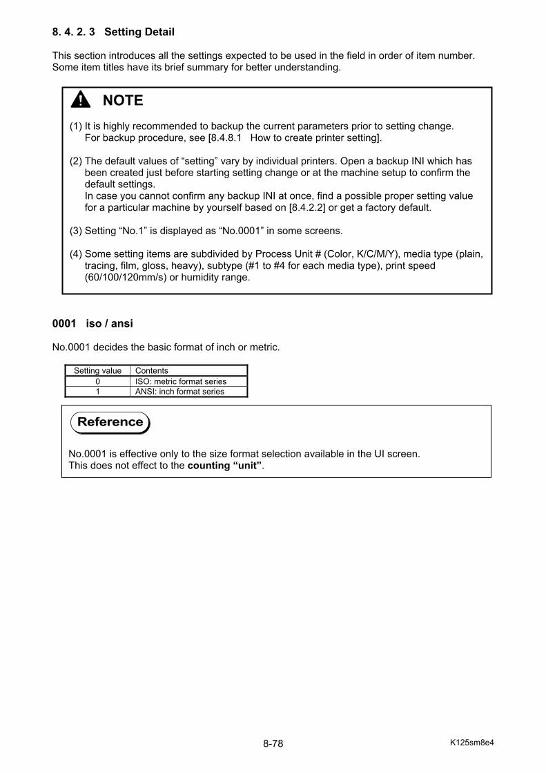
K125sm8e4 8-78
8. 4. 2. 3 Setting Detail This section introduces all the settings expected to be used in the field in order of item number. Some item titles have its brief summary for better understanding. 0001 iso / ansi No.0001 decides the basic format of inch or metric.
Setting value Contents 0 ISO: metric format series 1 ANSI: inch format series
Reference
No.0001 is effective only to the size format selection available in the UI screen. This does not effect to the counting “unit”.
NOTE (1) It is highly recommended to backup the current parameters prior to setting change.
For backup procedure, see [8.4.8.1 How to create printer setting]. (2) The default values of “setting” vary by individual printers. Open a backup INI which has
been created just before starting setting change or at the machine setup to confirm the default settings. In case you cannot confirm any backup INI at once, find a possible proper setting value for a particular machine by yourself based on [8.4.2.2] or get a factory default.
(3) Setting “No.1” is displayed as “No.0001” in some screens. (4) Some setting items are subdivided by Process Unit # (Color, K/C/M/Y), media type (plain,
tracing, film, gloss, heavy), subtype (#1 to #4 for each media type), print speed (60/100/120mm/s) or humidity range.
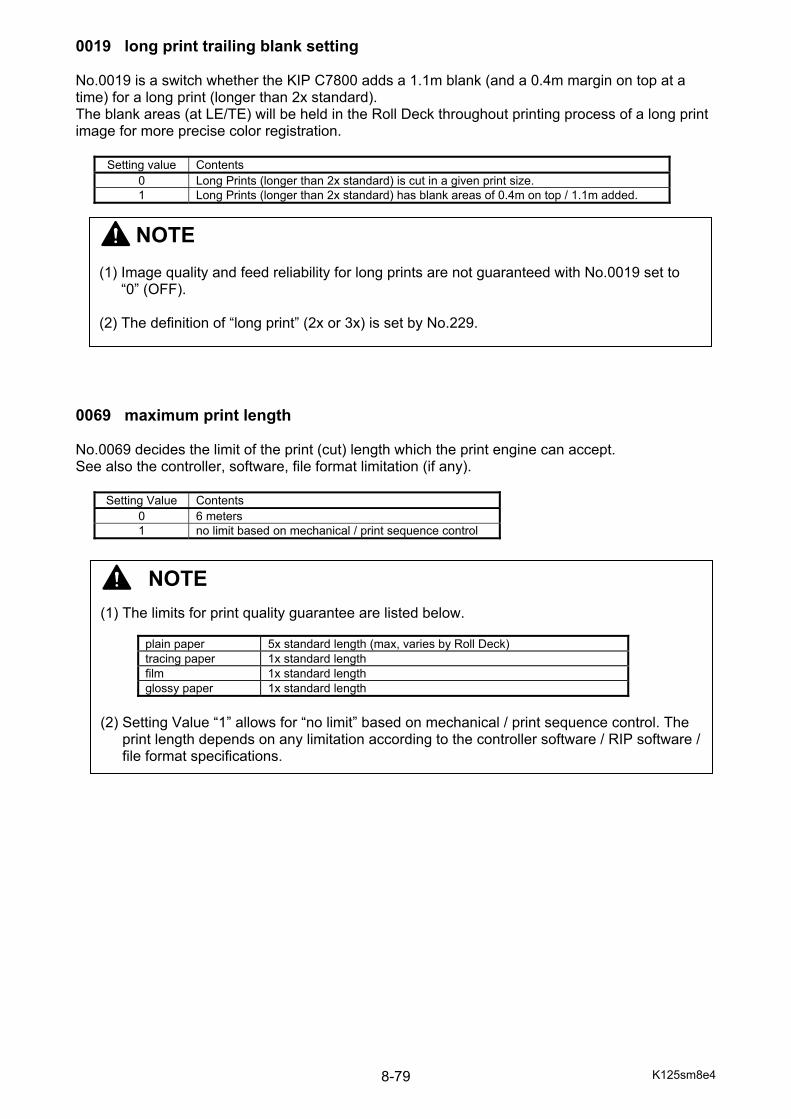
K125sm8e4 8-79
0019 long print trailing blank setting No.0019 is a switch whether the KIP C7800 adds a 1.1m blank (and a 0.4m margin on top at a time) for a long print (longer than 2x standard). The blank areas (at LE/TE) will be held in the Roll Deck throughout printing process of a long print image for more precise color registration.
Setting value Contents 0 Long Prints (longer than 2x standard) is cut in a given print size. 1 Long Prints (longer than 2x standard) has blank areas of 0.4m on top / 1.1m added.
0069 maximum print length No.0069 decides the limit of the print (cut) length which the print engine can accept. See also the controller, software, file format limitation (if any).
Setting Value Contents 0 6 meters 1 no limit based on mechanical / print sequence control
NOTE (1) The limits for print quality guarantee are listed below.
plain paper 5x standard length (max, varies by Roll Deck) tracing paper 1x standard length film 1x standard length glossy paper 1x standard length
(2) Setting Value “1” allows for “no limit” based on mechanical / print sequence control. The
print length depends on any limitation according to the controller software / RIP software / file format specifications.
NOTE (1) Image quality and feed reliability for long prints are not guaranteed with No.0019 set to
“0” (OFF). (2) The definition of “long print” (2x or 3x) is set by No.229.
K125sm8e4 8-80
0072 tension control target No.0072 is a parameter of the Fuser Tension Sensor to decide the Target Tension. (the standard angle of Fuser Entrance Guide) Increase the value to raise the Target Tension. 0073 tension control gain No.0073 is a parameter of speed change of Fuser Motor to maintain the Target Tension. Increasing the value gets a bigger unit of speed change of Fuser Motor. 0074 tension control offset delay No.0074 is a correction factor of speed change of Fuser Motor to maintain the Target Tension. Increasing the value gets a bigger unit of speed change of Fuser Motor. 0079 web feed No.0079 is a mode selector to change the pace of forwarding web cleaner. The faster web proceeds, the more cleaning performance comes.
Setting value Contents 0 Web proceeds by the standard speed, 0.15mm in 500mm printing. 1 Web proceeds by the standard speed, 0.3mm in 500mm printing. 2 Web proceeds by the standard speed, 0.6mm in 500mm printing.
0080 print end web setting No.0080 is a switch whether the KIP c7800 forwards the web cleaner in 3mm every after completion of a print operation.
Setting value Contents 0 Inactive 1 Web proceeds by 3mm after completion of a print operation to provide fresh web
cleaner surface.
NOTE This setting has been factory-adjusted. Keep the value unchanged.
NOTE Tension Control has been factory-adjusted in cooperation with No.0073 to 0079. Keep the value unchanged or Tension Control may malfunction.
NOTE Tension Control has been factory-adjusted in cooperation with No.0073 to 0079. Keep the value unchanged or Tension Control may malfunction.
K125sm8e4 8-81
0081 to 0092 image corona current No.0081 to 0092 set the output current to Image Corona. Increase the value for darker imaging.
Item No. Setting Item Setting Range
Step of Increment
0081 image corona current (K) 60mm/s 700 to 1700 1 micro A 0082 image corona current (C) 60mm/s 0083 image corona current (M) 60mm/s 0084 image corona current (Y) 60mm/s 0085 image corona current (K) 100mm/s 0086 image corona current (C) 100mm/s 0087 image corona current (M) 100mm/s 0088 image corona current (Y) 100mm/s 0089 image corona current (K) 120mm/s 0090 image corona current (C) 120mm/s 0091 image corona current (M) 120mm/s 0092 image corona current (Y) 120mm/s
0093 to 0104 grid bias No.0098 to 0104 set the output voltage to the Grid Plate. Increase the value for darker imaging.
Item No. Setting Item Setting Range
Step of Increment
0093 grid bias (K) 60mm/s 300 to 800 1V 0094 grid bias (C) 60mm/s 0095 grid bias (M) 60mm/s 0096 grid bias (Y) 60mm/s 0097 grid bias (K) 100mm/s 0098 grid bias (C) 100mm/s 0099 grid bias (M) 100mm/s 0100 grid bias (Y) 100mm/s 0101 grid bias (K) 120mm/s 0102 grid bias (C) 120mm/s 0103 grid bias (M) 120mm/s 0104 grid bias (Y) 120mm/s
NOTE This setting has been factory-adjusted. Keep the value unchanged.
NOTE This setting has been factory-adjusted. Keep the value unchanged.
K125sm8e4 8-82
0113 to 0116 developer roller bias (applied when pint speed is 100/120mm/sec) These are the voltage applied to the Developer Roller. These are applied when all of the following conditions are satisfied. - Auto Density Control is set to OFF. (Not applied when it is ON) - Density level is set to level 3 (of 5 levels) - Print speed is 100mm/sec (Bond/Vellum/Film in color mode) or 120mm/sec (monochrome) Increment of the value raise the voltage and eventually the printed image gets darker.
Item No. Setting Item Setting Range
Step of Increment
0113 developer roller bias (K) 100/120mm/sec 50 to 450 1V 0114 developer roller bias (C) 100/120mm/sec 0115 developer roller bias (M) 100/120mm/sec 0116 developer roller bias (Y) 100/120mm/sec
These are to be used for preparation of executing Density Lock. 0117 to 0120 supply roller bias No.0117 to 0120 set the output voltage to the Toner Supply Roller. Increase the value for darker imaging.
Item No. Setting Item Setting Range
Step of Increment
0117 supply roller bias (K) 10 to 500 1V 0118 supply roller bias (C) 0119 supply roller bias (M) 0120 supply roller bias (Y)
0125 to 0128 blade roller bias (applied when pint speed is 100/120mm/sec) No.0125 to 0128 set the output voltage to the Blade Roller, which is applied when print speed is 100mm/sec (Bond/Vellum/Film in color mode) or 120mm/sec (monochrome). Increment of the value makes toner layer on developer Roller thicker.
Item No. Setting Item Setting Range
Step of Increment
0125 blade roller bias (K) 100/120mm/sec 10 to 500 1V 0126 blade roller bias (C) 100/120mm/sec 0127 blade roller bias (M) 100/120mm/sec 0128 blade roller bias (Y) 100/120mm/sec
NOTE This setting has been factory-adjusted. Keep the value unchanged.
NOTE This setting has been factory-adjusted. Keep the value unchanged.
K125sm8e4 8-83
0139 to 0142 developer roller bias offset (applied when pint speed is 60mm/sec) These modes specify the offset of developer roller bias, which is applied only when the print speed is 60mm/sec (Gloss and Heavy in color mode). Setting value stands for the voltage differential from the standard developer roller bias which is specified by BUD No.113 to 116. If developer roller bias is set to 180 (-180V) in BUD No.113 (developer roller bias [K]) and also voltage differential is set to +10V in BUD No.139 (developer roller bias offset), the actual voltage applied to the developer roller is -170V being calculated by the following formula. -180 + 10 = -170 Increment of the value makes the printed image darker.
Item No. Setting Item Setting Range
Step of Increment
0139 Developer roller bias offset (K) 60mm/sec -50 to 50 1V 0140 Developer roller bias offset (C) 60mm/sec 0141 Developer roller bias offset (M) 60mm/sec 0142 Developer roller bias offset (Y) 60mm/sec
0143 to 0146 blade roller bias (applied when pint speed is 60mm/sec) No.0143 to 0146 set the output voltage to the Blade Roller, which is applied when print speed is 60mm/sec (monochrome). Increment of the value makes toner layer on developer Roller thicker.
Item No. Setting Item Setting Range
Step of Increment
0125 blade roller bias (K) 60mm/sec 10 to 500 1V 0126 blade roller bias (C) 60mm/sec 0127 blade roller bias (M) 60mm/sec 0128 blade roller bias (Y) 60mm/sec
0201 flapper control solenoid pwm duty (long print) This is the same with No.0207 to 0226 and is only applied to long prints.
Setting Range 0 to 100
NOTE Tension Control has been factory-adjusted in cooperation with No.0202. Keep the value unchanged or Tension Control may malfunction.
K125sm8e4 8-84
0202 tension control target (long print) This is the same with No.0072 and is only applied to long prints.
Setting Range 0 to 255
0203 lower transfer tension control target No.0203 is a parameter of the Lower Transfer Tension Sensor to decide the Target Tension on the mid-feed region. Increase the value to raise the Target Tension.
Setting Range 0 to 255
0204 lower transfer tension control gain No.0204 is a parameter of speed change of Feed Motor for mid-feed region to maintain the Target Tension. Increasing the value gets a bigger unit of speed change of Feed Motor.
Setting Range 0 to 255
NOTE This setting has been factory-adjusted. Keep the value unchanged.
NOTE This setting has been factory-adjusted. Keep the value unchanged.
NOTE Tension Control has been factory-adjusted in cooperation with No.0203. Keep the value unchanged or Tension Control may malfunction.
K125sm8e4 8-85
0205 mono print feed mode No.0205 decides the operation position for Process Units C/M/Y in monochrome printing. In monochrome printing, only the Process Unit K operates and the other Process Units C/M/Y stay at “standby position”. This feature allows the Process Units C/M/Y to operate as the color printing (without C/M/Y toner). Therefore, the media is transported by not only the Process Unit K but all the 4 Process Units to ensure media feed performance for narrower media.
Setting value Contents 0 Process Unit C/M/Y remains standby position while processing monochrome printing 1 Process Unit C/M/Y may move to operation position while processing monochrome
printing according to the fixed conditions. 2 Process Unit C/M/Y moves to operation position while processing monochrome
printing 0206 stacker select No.0206 is to recognize a finishing device (folder, stacker).
Setting value Contents 0 No Auto Stacker is used. / Folder is set to the printer. 1 (reserved: do not use) 2 Auto Stacker is used.
K125sm8e4 8-86
0207 to 0226 flapper control solenoid pwm duty The Fuser Entrance Guide detects its tilt due to pressure from the media tension. It has a rotary solenoid on its shaft, machine right side. These are a parameter of torque change on the rotary solenoid to decide the detection fineness of the tilted angle. Increasing the value increases the duty on the motion (= rises the torque) of the rotary solenoid, thus the Fuser Entrance Guide tilts in a less angle by a certain pressure. This is because the Fuser Entrance Guide can bear stronger media tension.
Item No. Setting Item
0207 flapper control solenoid pwm duty (plain #1) 0208 flapper control solenoid pwm duty (plain #2) 0209 flapper control solenoid pwm duty (plain #3) 0210 flapper control solenoid pwm duty (plain #4) 0211 flapper control solenoid pwm duty (tracing paper #1) 0212 flapper control solenoid pwm duty (tracing paper #2) 0213 flapper control solenoid pwm duty (tracing paper #3) 0214 flapper control solenoid pwm duty (tracing paper #4) 0215 flapper control solenoid pwm duty (film #1) 0216 flapper control solenoid pwm duty (film #2) 0217 flapper control solenoid pwm duty (film #3) 0218 flapper control solenoid pwm duty (film #4) 0219 flapper control solenoid pwm duty (glossy #1) 0220 flapper control solenoid pwm duty (glossy #2) 0221 flapper control solenoid pwm duty (glossy #3) 0222 flapper control solenoid pwm duty (glossy #4) 0223 flapper control solenoid pwm duty (heavy #1) 0224 flapper control solenoid pwm duty (heavy #2) 0225 flapper control solenoid pwm duty (heavy #3) 0226 flapper control solenoid pwm duty (heavy #4)
0229 long print control change point This defines the minimum length of “long print”. Setting value 20 defines that the long print is “twice as long as each standard portrait length”. Defined lengths are different per media widths such as; - 841mm wide roll media : 2378mm or longer is judges as long print (1189mm x2=2378mm) - 594mm side roll media : 1982mm or longer is judges as long print (841mm x2=1982mm)
Setting Range Step of Increment 20 to 30 0.1m
When a print is longer than (or just as long as) the defined length, the printer takes automatic tension control by the Tension Roller in the Bottom Transportation Unit. Maximum length available is "3 times as long as standard size" which is achieved when this is set to 30.
NOTE Tension Control has been factory-adjusted in cooperation with No.0207 to 0226. Keep the value unchanged or Tension Control may malfunction.
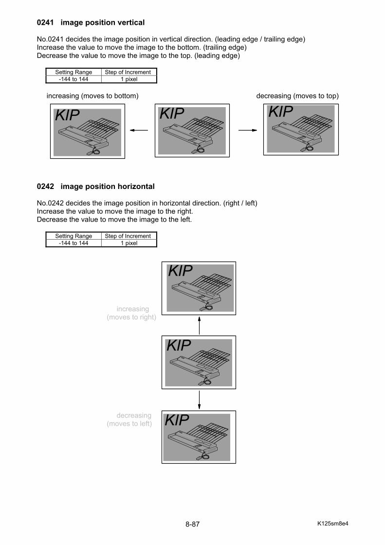
K125sm8e4 8-87
0241 image position vertical No.0241 decides the image position in vertical direction. (leading edge / trailing edge) Increase the value to move the image to the bottom. (trailing edge) Decrease the value to move the image to the top. (leading edge)
Setting Range Step of Increment -144 to 144 1 pixel
increasing (moves to bottom) decreasing (moves to top)
0242 image position horizontal No.0242 decides the image position in horizontal direction. (right / left) Increase the value to move the image to the right. Decrease the value to move the image to the left.
Setting Range Step of Increment -144 to 144 1 pixel
increasing (moves to right) decreasing (moves to left)
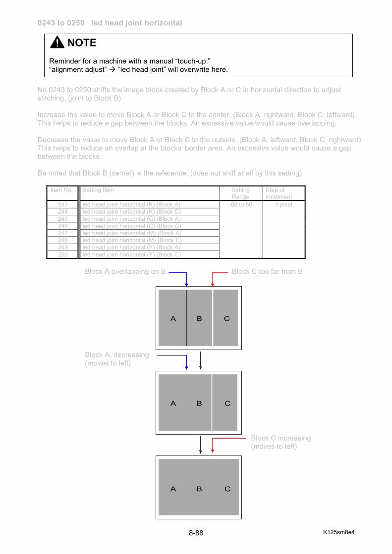
K125sm8e4 8-88
0243 to 0250 led head joint horizontal No.0243 to 0250 shifts the image block created by Block A or C in horizontal direction to adjust stitching. (joint to Block B) Increase the value to move Block A or Block C to the center. (Block A: rightward, Block C: leftward) This helps to reduce a gap between the blocks. An excessive value would cause overlapping. Decrease the value to move Block A or Block C to the outside. (Block A: leftward, Block C: rightward) This helps to reduce an overlap at the blocks’ border area. An excessive value would cause a gap between the blocks. Be noted that Block B (center) is the reference. (does not shift at all by this setting)
Item No. Setting Item Setting Range
Step of Increment
243 led head joint horizontal (K) (Block A) -60 to 60 1 pixel 244 led head joint horizontal (K) (Block C) 245 led head joint horizontal (C) (Block A) 246 led head joint horizontal (C) (Block C) 247 led head joint horizontal (M) (Block A) 248 led head joint horizontal (M) (Block C) 249 led head joint horizontal (Y) (Block A) 250 led head joint horizontal (Y) (Block C)
Block A overlapping on B Block C too far from B
Block A: decreasing (moves to left) Block C increasing (moves to left)
A B C
A B C
A B C
NOTE Reminder for a machine with a manual “touch-up.” “alignment adjust“ “led head joint” will overwrite here.
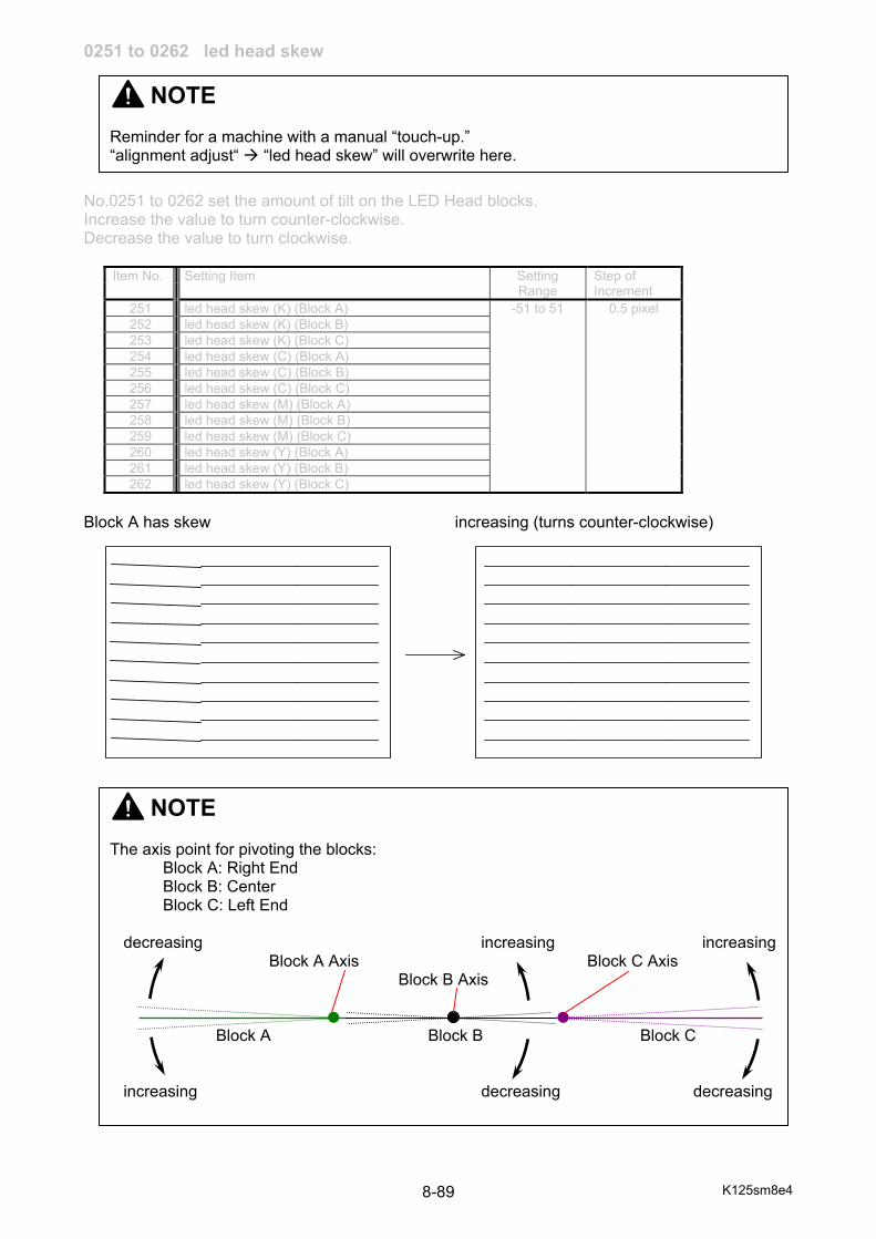
K125sm8e4 8-89
0251 to 0262 led head skew No.0251 to 0262 set the amount of tilt on the LED Head blocks. Increase the value to turn counter-clockwise. Decrease the value to turn clockwise.
Item No. Setting Item Setting Range
Step of Increment
251 led head skew (K) (Block A) -51 to 51 0.5 pixel 252 led head skew (K) (Block B) 253 led head skew (K) (Block C) 254 led head skew (C) (Block A) 255 led head skew (C) (Block B) 256 led head skew (C) (Block C) 257 led head skew (M) (Block A) 258 led head skew (M) (Block B) 259 led head skew (M) (Block C) 260 led head skew (Y) (Block A) 261 led head skew (Y) (Block B) 262 led head skew (Y) (Block C)
Block A has skew increasing (turns counter-clockwise)
NOTE The axis point for pivoting the blocks: Block A: Right End Block B: Center Block C: Left End decreasing increasing increasing Block A Axis Block C Axis
Block B Axis Block A Block B Block C increasing decreasing decreasing
NOTE Reminder for a machine with a manual “touch-up.” “alignment adjust“ “led head skew” will overwrite here.
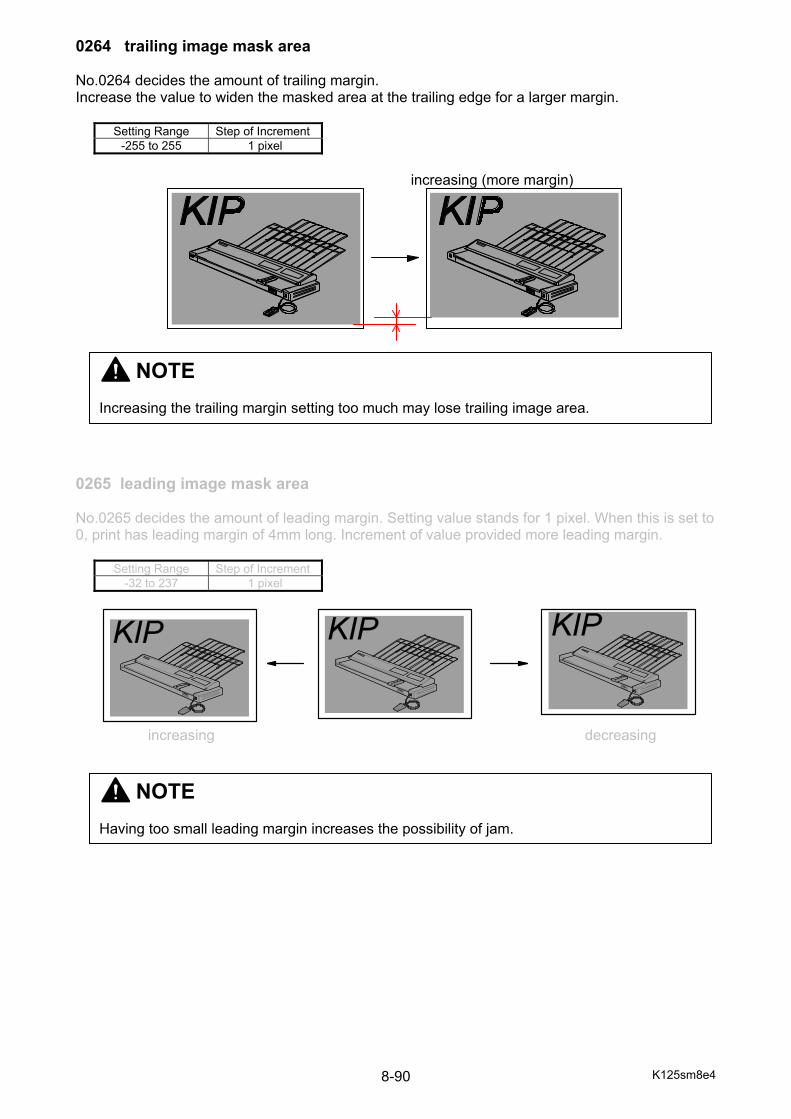
K125sm8e4 8-90
0264 trailing image mask area No.0264 decides the amount of trailing margin. Increase the value to widen the masked area at the trailing edge for a larger margin.
Setting Range Step of Increment -255 to 255 1 pixel
increasing (more margin) 0265 leading image mask area No.0265 decides the amount of leading margin. Setting value stands for 1 pixel. When this is set to 0, print has leading margin of 4mm long. Increment of value provided more leading margin.
Setting Range Step of Increment -32 to 237 1 pixel
increasing decreasing
NOTE Increasing the trailing margin setting too much may lose trailing image area.
NOTE Having too small leading margin increases the possibility of jam.
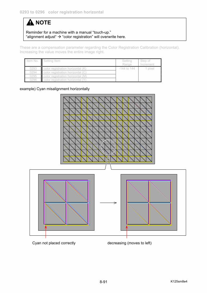
K125sm8e4 8-91
0293 to 0296 color registration horizontal These are a compensation parameter regarding the Color Registration Calibration (horizontal). Increasing the value moves the entire image right.
Item No. Setting Item Setting Range
Step of Increment
0293 color registration horizontal (K) -144 to 144 1 pixel 0294 color registration horizontal (C) 0295 color registration horizontal (M) 0296 color registration horizontal (Y)
example) Cyan misalignment horizontally Cyan not placed correctly decreasing (moves to left)
NOTE Reminder for a machine with a manual “touch-up.” “alignment adjust“ “color registration” will overwrite here.

K125sm8e4 8-92
0302 / 0305 / 0308 / 0311 color registration vertical These are a compensation parameter regarding the Color Registration Calibration (vertical). Increasing the value moves the entire image toward the trailing edge.
Item No. Setting Item Setting Range
Step of Increment
0302 color registration vertical (K) -288 to 288 0.5 pixel 0305 color registration vertical (C) 0308 color registration vertical (M) 0311 color registration vertical (Y)
example) Magenta misalignment vertically Magenta not placed correctly decreasing (moves to top)
NOTE Reminder for a machine with a manual “touch-up.” “alignment adjust“ “color registration” will overwrite here.
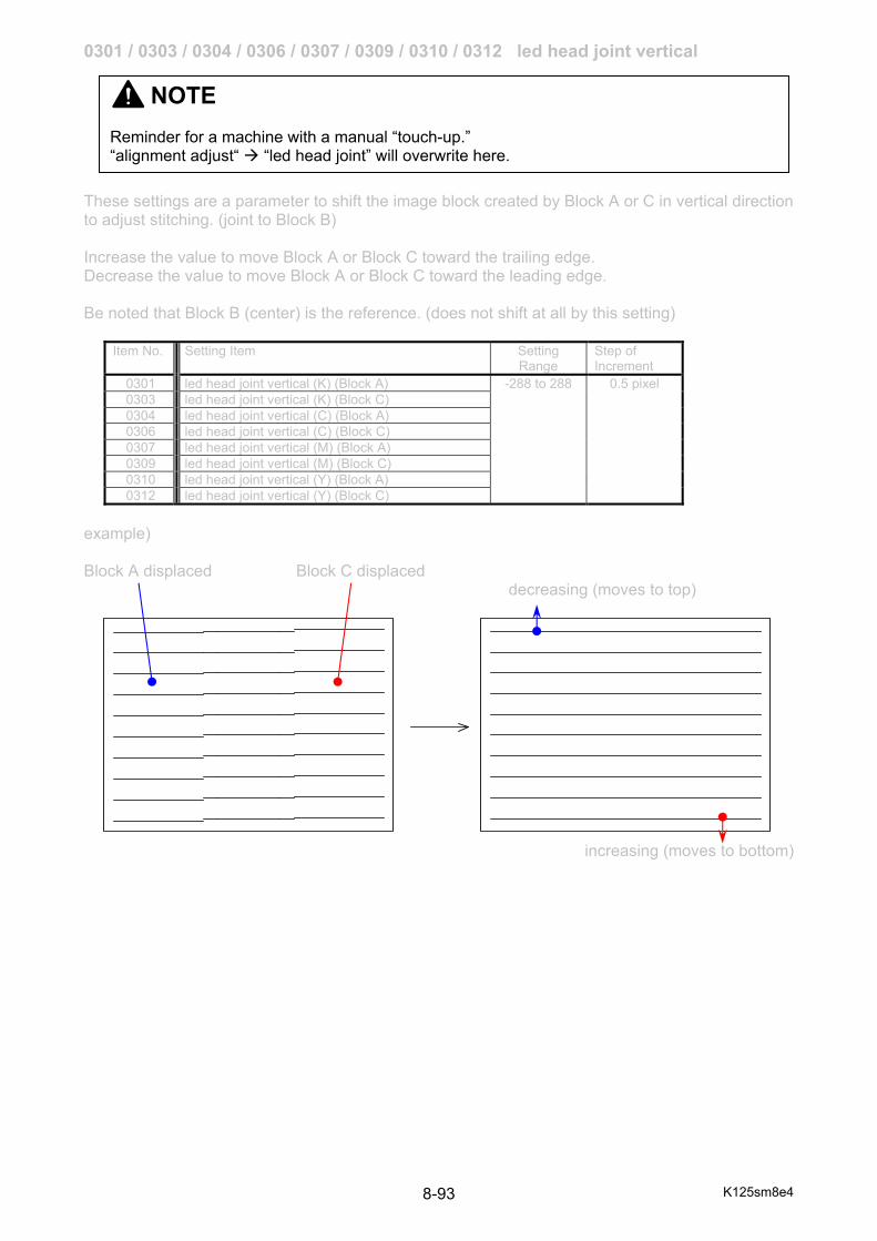
K125sm8e4 8-93
0301 / 0303 / 0304 / 0306 / 0307 / 0309 / 0310 / 0312 led head joint vertical These settings are a parameter to shift the image block created by Block A or C in vertical direction to adjust stitching. (joint to Block B) Increase the value to move Block A or Block C toward the trailing edge. Decrease the value to move Block A or Block C toward the leading edge. Be noted that Block B (center) is the reference. (does not shift at all by this setting)
Item No. Setting Item Setting Range
Step of Increment
0301 led head joint vertical (K) (Block A) -288 to 288 0.5 pixel 0303 led head joint vertical (K) (Block C) 0304 led head joint vertical (C) (Block A) 0306 led head joint vertical (C) (Block C) 0307 led head joint vertical (M) (Block A) 0309 led head joint vertical (M) (Block C) 0310 led head joint vertical (Y) (Block A) 0312 led head joint vertical (Y) (Block C)
example) Block A displaced Block C displaced decreasing (moves to top)
increasing (moves to bottom)
NOTE Reminder for a machine with a manual “touch-up.” “alignment adjust“ “led head joint” will overwrite here.
K125sm8e4 8-94
0316 to 0319 color registration vertical offset These are a touch-up offset for color registration vertical that will be effective on the result of any auto adjustment/calibration. Increasing the value moves the entire image toward the trailing edge.
Item No. Setting Item Setting Range
0316 Color registration vertical offset (K) -10 to 10 0317 Color registration vertical offset (C) 0318 Color registration vertical offset (M) 0319 Color registration vertical offset (Y)
0321 to 0324 transfer roller current No.321 to 324 set a limitation of the output current to Transfer Roller. When this is set to 500 the output voltage to Transfer Roller is fixed to certain value.
Item No. Setting Item Setting Range
Step of Increment
0321 transfer roller current (K) 50 to 500 1 micro A 0322 transfer roller current (C) 0323 transfer roller current (M) 0324 transfer roller current (Y)
0325 to 0327 transfer roller voltage select These are a mode selector whether Transfer Roller Bias is applied to Transfer Rollers C / M / Y while printing in Print Mode “mono” (120mm/s) with the rollers at “standby position” controlled by “No.205 mono print .feed mode”. According to the current setting of “mono print feed mode” even if Transfer Rollers C / M / Y are not set in operation position, Transfer Roller Bias C / M / Y will be applied to help media feed balance.
Item No. Setting Item Setting Range
0325 transfer roller voltage select (C) 0 or 1 0326 transfer roller voltage select (M) 0327 transfer roller voltage select (Y)
Setting value Contents 0 No Transfer Roller Bias is applied to the selected Transfer
Roller of C / M / Y staying at standby position. 1 Transfer Roller Bias applied to the selected Transfer Roller of
C / M / Y in mono print even Transfer Rollers stay at standby position.
NOTE This setting has been factory-adjusted. Keep the value unchanged.
NOTE This must be set to 500, and no other value is acceptable.
K125sm8e4 8-95
0361 counter-a config 0362 counter-b config No.0361 / No.0362 decide the counting unit for Counter A (color) / Counter B (mono).
Setting value Contents 0 1 linear meter 1 0.1 linear meter 2 1 square meter 3 0.1 square meter 4 1 linear foot 5 1 square foot 6 size count
0363 counter-a data 0366 counter-b data 0369 total counter data No.0363 / No.0366 / No.0369 rewrites the counter value for Counter A / Counter B / Total Count logically.
Reference
Size Count: A4/A3 : 1 count A2 : 2 counts A1 : 3 counts A0 : 5 counts
NOTE (1) This is not to be used when you replace PW12520 PCB and restore the settings with a
backup INI. The counter values are always saved in a backup INI file. Importing the file asks you to import the counter values as well as “setting” parameters.
(2) This is not to be used when you replace the memory storage (SSD) in the controller. The
counter values will synchronize with the value on the PW12520 memory.

K125sm8e4 8-96
0441 to 0456 transfer roller voltage (K, 60mm/s plain) No.0441 to 0520 set the output voltage to the Transfer Roller for Black that is applied when the print speed is 60mm/sec. Increment or decrement of the value affects the density or degree of foggy background. Note that change of the value for only film related items (473 to 488) actually affects the print result. Items for all other medias are disabled, so nothing happens even if you change the value.
0457 to 0472 transfer roller voltage (K, 60mm/s tracing)
Item No. Setting Item Subtype Humidity%RH
Setting Range
Step of increment
0441 transfer roller voltage (K) Plain, 60mm/s #1 5% 200 to 2000 1V 0442 transfer roller voltage (K) Plain, 60mm/s 20% 0443 transfer roller voltage (K) Plain, 60mm/s 40% 0444 transfer roller voltage (K) Plain, 60mm/s 60% 0445 transfer roller voltage (K) Plain, 60mm/s #2 5% 0446 transfer roller voltage (K) Plain, 60mm/s 20% 0447 transfer roller voltage (K) Plain, 60mm/s 40% 0448 transfer roller voltage (K) Plain, 60mm/s 60% 0449 transfer roller voltage (K) Plain, 60mm/s #3 5% 0450 transfer roller voltage (K) Plain, 60mm/s 20% 0451 transfer roller voltage (K) Plain, 60mm/s 40% 0452 transfer roller voltage (K) Plain, 60mm/s 60% 0453 transfer roller voltage (K) Plain, 60mm/s #4 5% 0454 transfer roller voltage (K) Plain, 60mm/s 20% 0455 transfer roller voltage (K) Plain, 60mm/s 40% 0456 transfer roller voltage (K) Plain, 60mm/s 60%
Item No. Setting Item Subtype Humidity%RH
Setting Range
Step of increment
0457 transfer roller voltage (K) Tracing, 60mm/s #1 5% 200 to 2000 1V 0458 transfer roller voltage (K) Tracing, 60mm/s 20% 0459 transfer roller voltage (K) Tracing, 60mm/s 40% 0460 transfer roller voltage (K) Tracing, 60mm/s 60% 0461 transfer roller voltage (K) Tracing, 60mm/s #2 5% 0462 transfer roller voltage (K) Tracing, 60mm/s 20% 0463 transfer roller voltage (K) Tracing, 60mm/s 40% 0464 transfer roller voltage (K) Tracing, 60mm/s 60% 0465 transfer roller voltage (K) Tracing, 60mm/s #3 5% 0466 transfer roller voltage (K) Tracing, 60mm/s 20% 0467 transfer roller voltage (K) Tracing, 60mm/s 40% 0468 transfer roller voltage (K) Tracing, 60mm/s 60% 0469 transfer roller voltage (K) Tracing, 60mm/s #4 5% 0470 transfer roller voltage (K) Tracing, 60mm/s 20% 0471 transfer roller voltage (K) Tracing, 60mm/s 40% 0472 transfer roller voltage (K) Tracing, 60mm/s 60%

K125sm8e4 8-97
0473 to 0488 transfer roller voltage (K, 60mm/s film)
0489 to 0504 transfer roller voltage (K, 60mm/s gloss)
0505 to 0520 transfer roller voltage (K, 60mm/s heavy)
Item No. Setting Item Subtype Humidity%RH
Setting Range
Step of increment
0473 transfer roller voltage (K) Film, 60mm/s #1 5% 200 to 2000 1V 0474 transfer roller voltage (K) Film, 60mm/s 20% 0475 transfer roller voltage (K) Film, 60mm/s 40% 0476 transfer roller voltage (K) Film, 60mm/s 60% 0477 transfer roller voltage (K) Film, 60mm/s #2 5% 0478 transfer roller voltage (K) Film, 60mm/s 20% 0479 transfer roller voltage (K) Film, 60mm/s 40% 0480 transfer roller voltage (K) Film, 60mm/s 60% 0481 transfer roller voltage (K) Film, 60mm/s #3 5% 0482 transfer roller voltage (K) Film, 60mm/s 20% 0483 transfer roller voltage (K) Film, 60mm/s 40% 0484 transfer roller voltage (K) Film, 60mm/s 60% 0485 transfer roller voltage (K) Film, 60mm/s #4 5% 0486 transfer roller voltage (K) Film, 60mm/s 20% 0487 transfer roller voltage (K) Film, 60mm/s 40% 0488 transfer roller voltage (K) Film, 60mm/s 60%
Item No. Setting Item Subtype Humidity%RH
Setting Range
Step of increment
0489 transfer roller voltage (K) Glossy, 60mm/s #1 5% 200 to 2000 1V 0490 transfer roller voltage (K) Glossy, 60mm/s 20% 0491 transfer roller voltage (K) Glossy, 60mm/s 40% 0492 transfer roller voltage (K) Glossy, 60mm/s 60% 0493 transfer roller voltage (K) Glossy, 60mm/s #2 5% 0494 transfer roller voltage (K) Glossy, 60mm/s 20% 0495 transfer roller voltage (K) Glossy, 60mm/s 40% 0496 transfer roller voltage (K) Glossy, 60mm/s 60% 0497 transfer roller voltage (K) Glossy, 60mm/s #3 5% 0498 transfer roller voltage (K) Glossy, 60mm/s 20% 0499 transfer roller voltage (K) Glossy, 60mm/s 40% 0500 transfer roller voltage (K) Glossy, 60mm/s 60% 0501 transfer roller voltage (K) Glossy, 60mm/s #4 5% 0502 transfer roller voltage (K) Glossy, 60mm/s 20% 0503 transfer roller voltage (K) Glossy, 60mm/s 40% 0504 transfer roller voltage (K) Glossy, 60mm/s 60%
Item No. Setting Item Subtype Humidity%RH
Setting Range
Step of increment
0505 transfer roller voltage (K) Heavy, 60mm/s #1 5% 200 to 2000 1V 0506 transfer roller voltage (K) Heavy, 60mm/s 20% 0507 transfer roller voltage (K) Heavy, 60mm/s 40% 0508 transfer roller voltage (K) Heavy, 60mm/s 60% 0509 transfer roller voltage (K) Heavy, 60mm/s #2 5% 0510 transfer roller voltage (K) Heavy, 60mm/s 20% 0511 transfer roller voltage (K) Heavy, 60mm/s 40% 0512 transfer roller voltage (K) Heavy, 60mm/s 60% 0513 transfer roller voltage (K) Heavy, 60mm/s #3 5% 0514 transfer roller voltage (K) Heavy, 60mm/s 20% 0515 transfer roller voltage (K) Heavy, 60mm/s 40% 0516 transfer roller voltage (K) Heavy, 60mm/s 60% 0517 transfer roller voltage (K) Heavy, 60mm/s #4 5% 0518 transfer roller voltage (K) Heavy, 60mm/s 20% 0519 transfer roller voltage (K) Heavy, 60mm/s 40% 0520 transfer roller voltage (K) Heavy, 60mm/s 60%
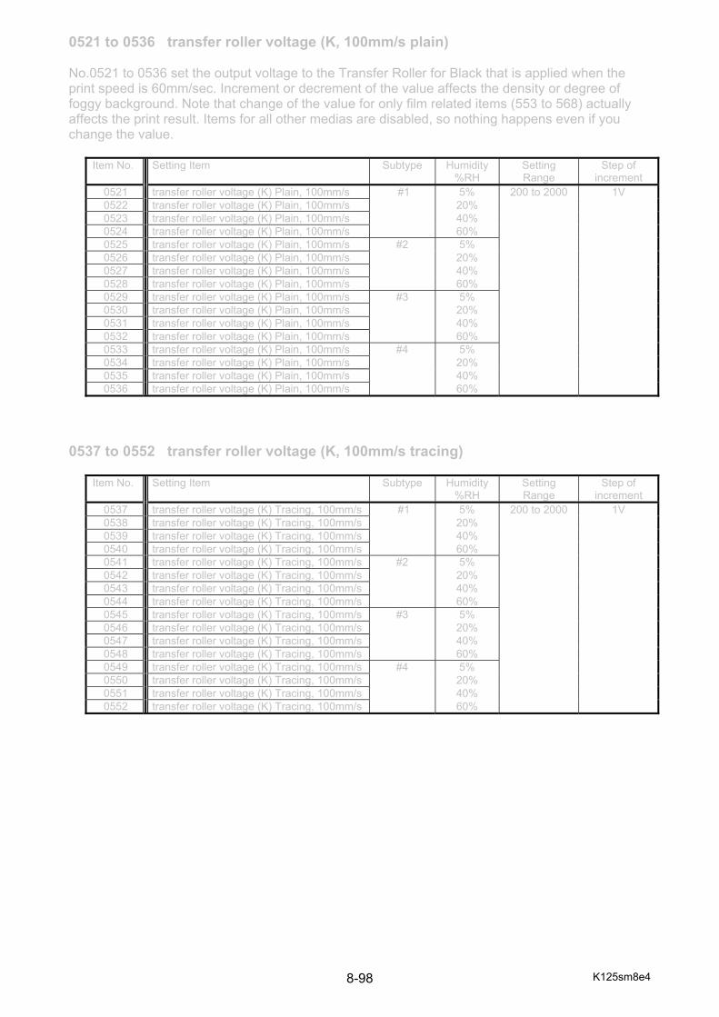
K125sm8e4 8-98
0521 to 0536 transfer roller voltage (K, 100mm/s plain) No.0521 to 0536 set the output voltage to the Transfer Roller for Black that is applied when the print speed is 60mm/sec. Increment or decrement of the value affects the density or degree of foggy background. Note that change of the value for only film related items (553 to 568) actually affects the print result. Items for all other medias are disabled, so nothing happens even if you change the value.
0537 to 0552 transfer roller voltage (K, 100mm/s tracing)
Item No. Setting Item Subtype Humidity%RH
Setting Range
Step of increment
0521 transfer roller voltage (K) Plain, 100mm/s #1 5% 200 to 2000 1V 0522 transfer roller voltage (K) Plain, 100mm/s 20% 0523 transfer roller voltage (K) Plain, 100mm/s 40% 0524 transfer roller voltage (K) Plain, 100mm/s 60% 0525 transfer roller voltage (K) Plain, 100mm/s #2 5% 0526 transfer roller voltage (K) Plain, 100mm/s 20% 0527 transfer roller voltage (K) Plain, 100mm/s 40% 0528 transfer roller voltage (K) Plain, 100mm/s 60% 0529 transfer roller voltage (K) Plain, 100mm/s #3 5% 0530 transfer roller voltage (K) Plain, 100mm/s 20% 0531 transfer roller voltage (K) Plain, 100mm/s 40% 0532 transfer roller voltage (K) Plain, 100mm/s 60% 0533 transfer roller voltage (K) Plain, 100mm/s #4 5% 0534 transfer roller voltage (K) Plain, 100mm/s 20% 0535 transfer roller voltage (K) Plain, 100mm/s 40% 0536 transfer roller voltage (K) Plain, 100mm/s 60%
Item No. Setting Item Subtype Humidity%RH
Setting Range
Step of increment
0537 transfer roller voltage (K) Tracing, 100mm/s #1 5% 200 to 2000 1V 0538 transfer roller voltage (K) Tracing, 100mm/s 20% 0539 transfer roller voltage (K) Tracing, 100mm/s 40% 0540 transfer roller voltage (K) Tracing, 100mm/s 60% 0541 transfer roller voltage (K) Tracing, 100mm/s #2 5% 0542 transfer roller voltage (K) Tracing, 100mm/s 20% 0543 transfer roller voltage (K) Tracing, 100mm/s 40% 0544 transfer roller voltage (K) Tracing, 100mm/s 60% 0545 transfer roller voltage (K) Tracing, 100mm/s #3 5% 0546 transfer roller voltage (K) Tracing, 100mm/s 20% 0547 transfer roller voltage (K) Tracing, 100mm/s 40% 0548 transfer roller voltage (K) Tracing, 100mm/s 60% 0549 transfer roller voltage (K) Tracing, 100mm/s #4 5% 0550 transfer roller voltage (K) Tracing, 100mm/s 20% 0551 transfer roller voltage (K) Tracing, 100mm/s 40% 0552 transfer roller voltage (K) Tracing, 100mm/s 60%

K125sm8e4 8-99
0553 to 0568 transfer roller voltage (K, 100mm/s film)
0569 to 0584 transfer roller voltage (K, 100mm/s gloss)
0585 to 0600 transfer roller voltage (K, 100mm/s heavy)
Item No. Setting Item Subtype Humidity%RH
Setting Range
Step of increment
0553 transfer roller voltage (K) Film, 100mm/s #1 5% 200 to 2000 1V 0554 transfer roller voltage (K) Film, 100mm/s 20% 0555 transfer roller voltage (K) Film, 100mm/s 40% 0556 transfer roller voltage (K) Film, 100mm/s 60% 0557 transfer roller voltage (K) Film, 100mm/s #2 5% 0558 transfer roller voltage (K) Film, 100mm/s 20% 0559 transfer roller voltage (K) Film, 100mm/s 40% 0560 transfer roller voltage (K) Film, 100mm/s 60% 0561 transfer roller voltage (K) Film, 100mm/s #3 5% 0562 transfer roller voltage (K) Film, 100mm/s 20% 0563 transfer roller voltage (K) Film, 100mm/s 40% 0564 transfer roller voltage (K) Film, 100mm/s 60% 0565 transfer roller voltage (K) Film, 100mm/s #4 5% 0566 transfer roller voltage (K) Film, 100mm/s 20% 0567 transfer roller voltage (K) Film, 100mm/s 40% 0568 transfer roller voltage (K) Film, 100mm/s 60%
Item No. Setting Item Subtype Humidity%RH
Setting Range
Step of increment
0569 transfer roller voltage (K) Glossy, 100mm/s #1 5% 200 to 2000 1V 0570 transfer roller voltage (K) Glossy, 100mm/s 20% 0571 transfer roller voltage (K) Glossy, 100mm/s 40% 0572 transfer roller voltage (K) Glossy, 100mm/s 60% 0573 transfer roller voltage (K) Glossy, 100mm/s #2 5% 0574 transfer roller voltage (K) Glossy, 100mm/s 20% 0575 transfer roller voltage (K) Glossy, 100mm/s 40% 0576 transfer roller voltage (K) Glossy, 100mm/s 60% 0577 transfer roller voltage (K) Glossy, 100mm/s #3 5% 0578 transfer roller voltage (K) Glossy, 100mm/s 20% 0579 transfer roller voltage (K) Glossy, 100mm/s 40% 0580 transfer roller voltage (K) Glossy, 100mm/s 60% 0581 transfer roller voltage (K) Glossy, 100mm/s #4 5% 0582 transfer roller voltage (K) Glossy, 100mm/s 20% 0583 transfer roller voltage (K) Glossy, 100mm/s 40% 0584 transfer roller voltage (K) Glossy, 100mm/s 60%
Item No. Setting Item Subtype Humidity%RH
Setting Range
Step of increment
0585 transfer roller voltage (K) Heavy, 100mm/s #1 5% 200 to 2000 1V 0586 transfer roller voltage (K) Heavy, 100mm/s 20% 0587 transfer roller voltage (K) Heavy, 100mm/s 40% 0588 transfer roller voltage (K) Heavy, 100mm/s 60% 0589 transfer roller voltage (K) Heavy, 100mm/s #2 5% 0590 transfer roller voltage (K) Heavy, 100mm/s 20% 0591 transfer roller voltage (K) Heavy, 100mm/s 40% 0592 transfer roller voltage (K) Heavy, 100mm/s 60% 0593 transfer roller voltage (K) Heavy, 100mm/s #3 5% 0594 transfer roller voltage (K) Heavy, 100mm/s 20% 0595 transfer roller voltage (K) Heavy, 100mm/s 40% 0596 transfer roller voltage (K) Heavy, 100mm/s 60% 0597 transfer roller voltage (K) Heavy, 100mm/s #4 5% 0598 transfer roller voltage (K) Heavy, 100mm/s 20% 0599 transfer roller voltage (K) Heavy, 100mm/s 40% 0600 transfer roller voltage (K) Heavy, 100mm/s 60%

K125sm8e4 8-100
0601 to 0616 transfer roller voltage (K, 120mm/s plain) No.0601 to 0616 set the output voltage to the Transfer Roller for Black that is applied when the print speed is 60mm/sec. Increment or decrement of the value affects the density or degree of foggy background. Note that change of the value for only film related items (633 to 648) actually affects the print result. Items for all other medias are disabled, so nothing happens even if you change the value.
0617 to 0632 transfer roller voltage (K, 120mm/s tracing)
Item No. Setting Item Subtype Humidity%RH
Setting Range
Step of increment
0601 transfer roller voltage (K) Plain, 120mm/s #1 5% 200 to 2000 1V 0602 transfer roller voltage (K) Plain, 120mm/s 20% 0603 transfer roller voltage (K) Plain, 120mm/s 40% 0604 transfer roller voltage (K) Plain, 120mm/s 60% 0605 transfer roller voltage (K) Plain, 120mm/s #2 5% 0606 transfer roller voltage (K) Plain, 120mm/s 20% 0607 transfer roller voltage (K) Plain, 120mm/s 40% 0608 transfer roller voltage (K) Plain, 120mm/s 60% 0609 transfer roller voltage (K) Plain, 120mm/s #3 5% 0610 transfer roller voltage (K) Plain, 120mm/s 20% 0611 transfer roller voltage (K) Plain, 120mm/s 40% 0612 transfer roller voltage (K) Plain, 120mm/s 60% 0613 transfer roller voltage (K) Plain, 120mm/s #4 5% 0614 transfer roller voltage (K) Plain, 120mm/s 20% 0615 transfer roller voltage (K) Plain, 120mm/s 40% 0616 transfer roller voltage (K) Plain, 120mm/s 60%
Item No. Setting Item Subtype Humidity%RH
Setting Range
Step of increment
0617 transfer roller voltage (K) Tracing, 120mm/s #1 5% 200 to 2000 1V 0618 transfer roller voltage (K) Tracing, 120mm/s 20% 0619 transfer roller voltage (K) Tracing, 120mm/s 40% 0620 transfer roller voltage (K) Tracing, 120mm/s 60% 0621 transfer roller voltage (K) Tracing, 120mm/s #2 5% 0622 transfer roller voltage (K) Tracing, 120mm/s 20% 0623 transfer roller voltage (K) Tracing, 120mm/s 40% 0624 transfer roller voltage (K) Tracing, 120mm/s 60% 0625 transfer roller voltage (K) Tracing, 120mm/s #3 5% 0626 transfer roller voltage (K) Tracing, 120mm/s 20% 0627 transfer roller voltage (K) Tracing, 120mm/s 40% 0628 transfer roller voltage (K) Tracing, 120mm/s 60% 0629 transfer roller voltage (K) Tracing, 120mm/s #4 5% 0630 transfer roller voltage (K) Tracing, 120mm/s 20% 0631 transfer roller voltage (K) Tracing, 120mm/s 40% 0632 transfer roller voltage (K) Tracing, 120mm/s 60%

K125sm8e4 8-101
0633 to 0648 transfer roller voltage (K, 120mm/s film)
0649 to 0664 transfer roller voltage (K, 120mm/s gloss)
0665 to 0680 transfer roller voltage (K, 120mm/s heavy)
Item No. Setting Item Subtype Humidity%RH
Setting Range
Step of increment
0633 transfer roller voltage (K) Film, 120mm/s #1 5% 200 to 2000 1V 0634 transfer roller voltage (K) Film, 120mm/s 20% 0635 transfer roller voltage (K) Film, 120mm/s 40% 0636 transfer roller voltage (K) Film, 120mm/s 60% 0637 transfer roller voltage (K) Film, 120mm/s #2 5% 0638 transfer roller voltage (K) Film, 120mm/s 20% 0639 transfer roller voltage (K) Film, 120mm/s 40% 0640 transfer roller voltage (K) Film, 120mm/s 60% 0641 transfer roller voltage (K) Film, 120mm/s #3 5% 0642 transfer roller voltage (K) Film, 120mm/s 20% 0643 transfer roller voltage (K) Film, 120mm/s 40% 0644 transfer roller voltage (K) Film, 120mm/s 60% 0645 transfer roller voltage (K) Film, 120mm/s #4 5% 0646 transfer roller voltage (K) Film, 120mm/s 20% 0647 transfer roller voltage (K) Film, 120mm/s 40% 0648 transfer roller voltage (K) Film, 120mm/s 60%
Item No. Setting Item Subtype Humidity%RH
Setting Range
Step of increment
0649 transfer roller voltage (K) Glossy, 120mm/s #1 5% 200 to 2000 1V 0650 transfer roller voltage (K) Glossy, 120mm/s 20% 0651 transfer roller voltage (K) Glossy, 120mm/s 40% 0652 transfer roller voltage (K) Glossy, 120mm/s 60% 0653 transfer roller voltage (K) Glossy, 120mm/s #2 5% 0654 transfer roller voltage (K) Glossy, 120mm/s 20% 0655 transfer roller voltage (K) Glossy, 120mm/s 40% 0656 transfer roller voltage (K) Glossy, 120mm/s 60% 0657 transfer roller voltage (K) Glossy, 120mm/s #3 5% 0658 transfer roller voltage (K) Glossy, 120mm/s 20% 0659 transfer roller voltage (K) Glossy, 120mm/s 40% 0660 transfer roller voltage (K) Glossy, 120mm/s 60% 0661 transfer roller voltage (K) Glossy, 120mm/s #4 5% 0662 transfer roller voltage (K) Glossy, 120mm/s 20% 0663 transfer roller voltage (K) Glossy, 120mm/s 40% 0664 transfer roller voltage (K) Glossy, 120mm/s 60%
Item No. Setting Item Subtype Humidity%RH
Setting Range
Step of increment
0665 transfer roller voltage (K) Heavy, 120mm/s #1 5% 200 to 2000 1V 0666 transfer roller voltage (K) Heavy, 120mm/s 20% 0667 transfer roller voltage (K) Heavy, 120mm/s 40% 0668 transfer roller voltage (K) Heavy, 120mm/s 60% 0669 transfer roller voltage (K) Heavy, 120mm/s #2 5% 0670 transfer roller voltage (K) Heavy, 120mm/s 20% 0671 transfer roller voltage (K) Heavy, 120mm/s 40% 0672 transfer roller voltage (K) Heavy, 120mm/s 60% 0673 transfer roller voltage (K) Heavy, 120mm/s #3 5% 0674 transfer roller voltage (K) Heavy, 120mm/s 20% 0675 transfer roller voltage (K) Heavy, 120mm/s 40% 0676 transfer roller voltage (K) Heavy, 120mm/s 60% 0677 transfer roller voltage (K) Heavy, 120mm/s #4 5% 0678 transfer roller voltage (K) Heavy, 120mm/s 20% 0679 transfer roller voltage (K) Heavy, 120mm/s 40% 0680 transfer roller voltage (K) Heavy, 120mm/s 60%

K125sm8e4 8-102
0681 to 0696 transfer roller voltage (C, 60mm/s plain) No.0681 to 0696 set the output voltage to the Transfer Roller for Cyan that is applied when the print speed is 60mm/sec. Increment or decrement of the value affects the density or degree of foggy background. Note that change of the value for only film related items (713 to 728) actually affects the print result. Items for all other medias are disabled, so nothing happens even if you change the value.
0697 to 0712 transfer roller voltage (C, 60mm/s tracing)
Item No. Setting Item Subtype Humidity%RH
Setting Range
Step of increment
0681 transfer roller voltage (C) Plain, 60mm/s #1 5% 200 to 2000 1V 0682 transfer roller voltage (C) Plain, 60mm/s 20% 0683 transfer roller voltage (C) Plain, 60mm/s 40% 0684 transfer roller voltage (C) Plain, 60mm/s 60% 0685 transfer roller voltage (C) Plain, 60mm/s #2 5% 0686 transfer roller voltage (C) Plain, 60mm/s 20% 0687 transfer roller voltage (C) Plain, 60mm/s 40% 0688 transfer roller voltage (C) Plain, 60mm/s 60% 0689 transfer roller voltage (C) Plain, 60mm/s #3 5% 0690 transfer roller voltage (C) Plain, 60mm/s 20% 0691 transfer roller voltage (C) Plain, 60mm/s 40% 0692 transfer roller voltage (C) Plain, 60mm/s 60% 0693 transfer roller voltage (C) Plain, 60mm/s #4 5% 0694 transfer roller voltage (C) Plain, 60mm/s 20% 0695 transfer roller voltage (C) Plain, 60mm/s 40% 0696 transfer roller voltage (C) Plain, 60mm/s 60%
Item No. Setting Item Subtype Humidity%RH
Setting Range
Step of increment
0697 transfer roller voltage (C) Tracing, 60mm/s #1 5% 200 to 2000 1V 0698 transfer roller voltage (C) Tracing, 60mm/s 20% 0699 transfer roller voltage (C) Tracing, 60mm/s 40% 0700 transfer roller voltage (C) Tracing, 60mm/s 60% 0701 transfer roller voltage (C) Tracing, 60mm/s #2 5% 0702 transfer roller voltage (C) Tracing, 60mm/s 20% 0703 transfer roller voltage (C) Tracing, 60mm/s 40% 0704 transfer roller voltage (C) Tracing, 60mm/s 60% 0705 transfer roller voltage (C) Tracing, 60mm/s #3 5% 0706 transfer roller voltage (C) Tracing, 60mm/s 20% 0707 transfer roller voltage (C) Tracing, 60mm/s 40% 0708 transfer roller voltage (C) Tracing, 60mm/s 60% 0709 transfer roller voltage (C) Tracing, 60mm/s #4 5% 0710 transfer roller voltage (C) Tracing, 60mm/s 20% 0711 transfer roller voltage (C) Tracing, 60mm/s 40% 0712 transfer roller voltage (C) Tracing, 60mm/s 60%
K125sm8e4 8-103
0713 to 0728 transfer roller voltage (C, 60mm/s film)
0729 to 0744 transfer roller voltage (C, 60mm/s gloss)
0745 to 0760 transfer roller voltage (C, 60mm/s heavy)
Item No. Setting Item Subtype Humidity%RH
Setting Range
Step of increment
0713 transfer roller voltage (C) Film, 60mm/s #1 5% 200 to 2000 1V 0714 transfer roller voltage (C) Film, 60mm/s 20% 0715 transfer roller voltage (C) Film, 60mm/s 40% 0716 transfer roller voltage (C) Film, 60mm/s 60% 0717 transfer roller voltage (C) Film, 60mm/s #2 5% 0718 transfer roller voltage (C) Film, 60mm/s 20% 0719 transfer roller voltage (C) Film, 60mm/s 40% 0720 transfer roller voltage (C) Film, 60mm/s 60% 0721 transfer roller voltage (C) Film, 60mm/s #3 5% 0722 transfer roller voltage (C) Film, 60mm/s 20% 0723 transfer roller voltage (C) Film, 60mm/s 40% 0724 transfer roller voltage (C) Film, 60mm/s 60% 0725 transfer roller voltage (C) Film, 60mm/s #4 5% 0726 transfer roller voltage (C) Film, 60mm/s 20% 0727 transfer roller voltage (C) Film, 60mm/s 40% 0728 transfer roller voltage (C) Film, 60mm/s 60%
Item No. Setting Item Subtype Humidity%RH
Setting Range
Step of increment
0729 transfer roller voltage (C) Glossy, 60mm/s #1 5% 200 to 2000 1V 0730 transfer roller voltage (C) Glossy, 60mm/s 20% 0731 transfer roller voltage (C) Glossy, 60mm/s 40% 0732 transfer roller voltage (C) Glossy, 60mm/s 60% 0733 transfer roller voltage (C) Glossy, 60mm/s #2 5% 0734 transfer roller voltage (C) Glossy, 60mm/s 20% 0735 transfer roller voltage (C) Glossy, 60mm/s 40% 0736 transfer roller voltage (C) Glossy, 60mm/s 60% 0737 transfer roller voltage (C) Glossy, 60mm/s #3 5% 0738 transfer roller voltage (C) Glossy, 60mm/s 20% 0739 transfer roller voltage (C) Glossy, 60mm/s 40% 0740 transfer roller voltage (C) Glossy, 60mm/s 60% 0741 transfer roller voltage (C) Glossy, 60mm/s #4 5% 0742 transfer roller voltage (C) Glossy, 60mm/s 20% 0743 transfer roller voltage (C) Glossy, 60mm/s 40% 0744 transfer roller voltage (C) Glossy, 60mm/s 60%
Item No. Setting Item Subtype Humidity%RH
Setting Range
Step of increment
0745 transfer roller voltage (C) Heavy, 60mm/s #1 5% 200 to 2000 1V 0746 transfer roller voltage (C) Heavy, 60mm/s 20% 0747 transfer roller voltage (C) Heavy, 60mm/s 40% 0748 transfer roller voltage (C) Heavy, 60mm/s 60% 0749 transfer roller voltage (C) Heavy, 60mm/s #2 5% 0750 transfer roller voltage (C) Heavy, 60mm/s 20% 0751 transfer roller voltage (C) Heavy, 60mm/s 40% 0752 transfer roller voltage (C) Heavy, 60mm/s 60% 0753 transfer roller voltage (C) Heavy, 60mm/s #3 5% 0754 transfer roller voltage (C) Heavy, 60mm/s 20% 0755 transfer roller voltage (C) Heavy, 60mm/s 40% 0756 transfer roller voltage (C) Heavy, 60mm/s 60% 0757 transfer roller voltage (C) Heavy, 60mm/s #4 5% 0758 transfer roller voltage (C) Heavy, 60mm/s 20% 0759 transfer roller voltage (C) Heavy, 60mm/s 40% 0760 transfer roller voltage (C) Heavy, 60mm/s 60%
K125sm8e4 8-104
0761 to 0776 transfer roller voltage (C, 100mm/s plain) No.0761 to 0776 set the output voltage to the Transfer Roller for Cyan that is applied when the print speed is 100mm/sec. Increment or decrement of the value affects the density or degree of foggy background. Note that change of the value for only film related items (0793 to 0800, and 1481 to 1488) actually affects the print result. Items for all other medias are disabled, so nothing happens even if you change the value.
0777 to 0792 transfer roller voltage (C, 100mm/s tracing)
Item No. Setting Item Subtype Humidity%RH
Setting Range
Step of increment
0761 transfer roller voltage (C) Plain, 100mm/s #1 5% 200 to 2000 1V 0762 transfer roller voltage (C) Plain, 100mm/s 20% 0763 transfer roller voltage (C) Plain, 100mm/s 40% 0764 transfer roller voltage (C) Plain, 100mm/s 60% 0765 transfer roller voltage (C) Plain, 100mm/s #2 5% 0766 transfer roller voltage (C) Plain, 100mm/s 20% 0767 transfer roller voltage (C) Plain, 100mm/s 40% 0768 transfer roller voltage (C) Plain, 100mm/s 60% 0769 transfer roller voltage (C) Plain, 100mm/s #3 5% 0770 transfer roller voltage (C) Plain, 100mm/s 20% 0771 transfer roller voltage (C) Plain, 100mm/s 40% 0772 transfer roller voltage (C) Plain, 100mm/s 60% 0773 transfer roller voltage (C) Plain, 100mm/s #4 5% 0774 transfer roller voltage (C) Plain, 100mm/s 20% 0775 transfer roller voltage (C) Plain, 100mm/s 40% 0776 transfer roller voltage (C) Plain, 100mm/s 60%
Item No. Setting Item Subtype Humidity%RH
Setting Range
Step of increment
0777 transfer roller voltage (C) Tracing, 100mm/s #1 5% 200 to 2000 1V 0778 transfer roller voltage (C) Tracing, 100mm/s 20% 0779 transfer roller voltage (C) Tracing, 100mm/s 40% 0780 transfer roller voltage (C) Tracing, 100mm/s 60% 0781 transfer roller voltage (C) Tracing, 100mm/s #2 5% 0782 transfer roller voltage (C) Tracing, 100mm/s 20% 0783 transfer roller voltage (C) Tracing, 100mm/s 40% 0784 transfer roller voltage (C) Tracing, 100mm/s 60% 0785 transfer roller voltage (C) Tracing, 100mm/s #3 5% 0786 transfer roller voltage (C) Tracing, 100mm/s 20% 0787 transfer roller voltage (C) Tracing, 100mm/s 40% 0788 transfer roller voltage (C) Tracing, 100mm/s 60% 0789 transfer roller voltage (C) Tracing, 100mm/s #4 5% 0790 transfer roller voltage (C) Tracing, 100mm/s 20% 0791 transfer roller voltage (C) Tracing, 100mm/s 40% 0792 transfer roller voltage (C) Tracing, 100mm/s 60%
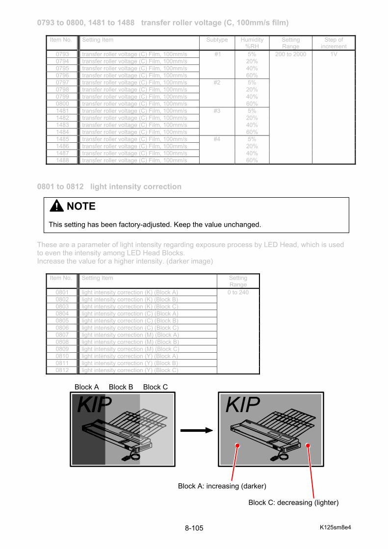
K125sm8e4 8-105
0793 to 0800, 1481 to 1488 transfer roller voltage (C, 100mm/s film)
0801 to 0812 light intensity correction These are a parameter of light intensity regarding exposure process by LED Head, which is used to even the intensity among LED Head Blocks. Increase the value for a higher intensity. (darker image)
Item No. Setting Item Setting Range
0801 light intensity correction (K) (Block A) 0 to 240 0802 light intensity correction (K) (Block B) 0803 light intensity correction (K) (Block C) 0804 light intensity correction (C) (Block A) 0805 light intensity correction (C) (Block B) 0806 light intensity correction (C) (Block C) 0807 light intensity correction (M) (Block A) 0808 light intensity correction (M) (Block B) 0809 light intensity correction (M) (Block C) 0810 light intensity correction (Y) (Block A) 0811 light intensity correction (Y) (Block B) 0812 light intensity correction (Y) (Block C)
Block A Block B Block C Block A: increasing (darker) Block C: decreasing (lighter)
Item No. Setting Item Subtype Humidity%RH
Setting Range
Step of increment
0793 transfer roller voltage (C) Film, 100mm/s #1 5% 200 to 2000 1V 0794 transfer roller voltage (C) Film, 100mm/s 20% 0795 transfer roller voltage (C) Film, 100mm/s 40% 0796 transfer roller voltage (C) Film, 100mm/s 60% 0797 transfer roller voltage (C) Film, 100mm/s #2 5% 0798 transfer roller voltage (C) Film, 100mm/s 20% 0799 transfer roller voltage (C) Film, 100mm/s 40% 0800 transfer roller voltage (C) Film, 100mm/s 60% 1481 transfer roller voltage (C) Film, 100mm/s #3 5% 1482 transfer roller voltage (C) Film, 100mm/s 20% 1483 transfer roller voltage (C) Film, 100mm/s 40% 1484 transfer roller voltage (C) Film, 100mm/s 60% 1485 transfer roller voltage (C) Film, 100mm/s #4 5% 1486 transfer roller voltage (C) Film, 100mm/s 20% 1487 transfer roller voltage (C) Film, 100mm/s 40% 1488 transfer roller voltage (C) Film, 100mm/s 60%
NOTE This setting has been factory-adjusted. Keep the value unchanged.
K125sm8e4 8-106
0813 to 0816 light gain These are a correction factor of light intensity regarding exposure process by LED Head. This will be effective on all LED Head Blocks on a particular process unit at a time. Increase the value for a higher intensity. (darker image) (basically 100)
Item No. Setting Item Setting Range
0813 light gain (K) 75 to 125 0814 light gain (C) 0815 light gain (M) 0816 light gain (Y)
0844 to 0852 deck motor No.0844 to 0852 decides the operation speed of Roll Deck Motor. Increase the value for a higher motor speed. (faster) Decrease the value for a lower motor speed. (slower)
Item No. Setting Item Setting Range Step of increment
0844 deck motor (Roll 1) 60mm/s -1000 to 1000 0.01% 0845 deck motor (Roll 2) 60mm/s 0846 deck motor (Roll 3) 60mm/s 0847 deck motor (Roll 1) 100mm/s 0848 deck motor (Roll 2) 100mm/s 0849 deck motor (Roll 3) 100mm/s 0850 deck motor (Roll 1) 120mm/s 0851 deck motor (Roll 2) 120mm/s 0852 deck motor (Roll 3) 120mm/s
0853 to 0855 lower transfer motor No.0853 to 0855 decides the operation speed of Lower Transport Motor. Increase the value for a higher motor speed. (faster) Decrease the value for a lower motor speed. (slower)
Item No. Setting Item Setting Range Step of increment
853 lower transfer motor (60mm/s) -1000 to 1000 0.01% 854 lower transfer motor (100mm/s) 855 lower transfer motor (120mm/s)
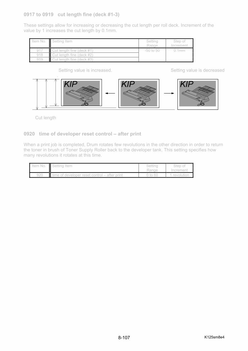
K125sm8e4 8-107
0917 to 0919 cut length fine (deck #1-3) These settings allow for increasing or decreasing the cut length per roll deck. Increment of the value by 1 increases the cut length by 0.1mm.
Item No. Setting Item Setting Range
Step of Increment
917 Cut length fine (deck #1) -50 to 50 0.1mm 918 Cut length fine (deck #2) 919 Cut length fine (deck #3)
Setting value is increased. Setting value is decreased
. Cut length 0920 time of developer reset control – after print When a print job is completed, Drum rotates few revolutions in the other direction in order to return the toner in brush of Toner Supply Roller back to the developer tank. This setting specifies how many revolutions it rotates at this time.
Item No. Setting Item Setting Range
Step of Increment
920 time of developer reset control – after print 0 to 60 1 revolution
K125sm8e4 8-108
1401 to 1470 image enhance table These are a parameter to decide the strength compensation for isolated pixel images, which is handled by Image Enhancement (IE). Selecting a higher value (= higher IE Level) enhances visual strength of isolated pixel images (looks darker).
Setting Value
IE Level Description
0 0 dot gets darker in the lowest degree 1 1 2 2 degree of image enhancement: less 3 3 4 4 5 5 6 6 7 7 8 8 9 9
10 10 11 11 12 12 13 13 degree of image enhancement: more 14 14 15 15 dot gets darker in the highest degree
(cont.)
NOTE This setting has been factory-adjusted. Keep the value unchanged.
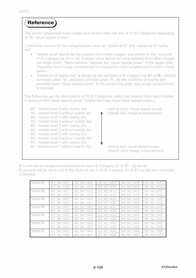
K125sm8e4 8-109
(cont.) IE Level can be assigned (customized) to each IE Category A1 to B5. (10 items) IE process will be set to one of the Mode (a set of 10 IE Category, #1 to #7) by the print controller. (7 Modes)
Mode #1 A1: No.1401 A2: No.1402 A3: No.1403 A4: No.1404 A5: No.1405 B1: No.1406 B2: No.1407 B3: No.1408 B4: No.1409 B5: No.1410 Mode #2 A1: No.1411 A2: No.1412 A3: No.1413 A4: No.1414 A5: No.1415 B1: No.1416 B2: No.1417 B3: No.1418 B4: No.1419 B5: No.1420 Mode #3 A1: No.1421 A2: No.1422 A3: No.1423 A4: No.1424 A5: No.1425 B1: No.1426 B2: No.1427 B3: No.1428 B4: No.1429 B5: No.1430 Mode #4 A1: No.1431 A2: No.1432 A3: No.1433 A4: No.1434 A5: No.1435 B1: No.1436 B2: No.1437 B3: No.1438 B4: No.1439 B5: No.1440 Mode #5 A1: No.1441 A2: No.1442 A3: No.1443 A4: No.1444 A5: No.1445 B1: No.1446 B2: No.1447 B3: No.1448 B4: No.1449 B5: No.1450 Mode #6 A1: No.1451 A2: No.1452 A3: No.1453 A4: No.1454 A5: No.1455 B1: No.1456 B2: No.1457 B3: No.1458 B4: No.1459 B5: No.1460 Mode #7 A1: No.1461 A2: No.1462 A3: No.1463 A4: No.1464 A5: No.1465 B1: No.1466 B2: No.1467 B3: No.1468 B4: No.1469 B5: No.1470
The printer categorizes every single pixel of print data into any of 10 IE Categories depending on its “visual appeal power”. 2 elements concern for the categorization, such as “isolate level” and “existence of nearby dot”.
• “Isolate level” stands for the isolation from other images, and shown by the “numeral” of IE Category as A1 or A2. A larger value stands for more isolation from other images (as single pixel). “More isolation” reduces the “visual appeal power” of the target pixel. Therefore more image enhancement is required for more isolated pixel to print it much darker.
• “Existence of nearby dot” is shown by the alphabet of IE Category as A1 or B1. Nearby dot exists when “B”, and does not exist when “A”. As the existence of nearby dot provides more “visual appeal power” to the concerning pixel, less image enhancement is required.
The followings are the descriptions of 10 IE Categories, which are ordered from top to bottom in terms of their visual appeal power. (Upper item has more visual appeal power.) B5 : Isolate level 5 with nearby dot Having much visual appeal power A5 : Isolate level 5 without nearby dot (Needs less image enhancement) B4 : Isolate level 4 with nearby dot A4 : Isolate level 4 without nearby dot B3 : Isolate level 3 with nearby dot A3 : Isolate level 3 without nearby dot B2 : Isolate level 2 with nearby dot A2 : Isolate level 2 without nearby dot B1 : Isolate level 1 with nearby dot A1 : Isolate level 1 without nearby dot Having less visual appeal power (Needs more image enhancement)
Reference
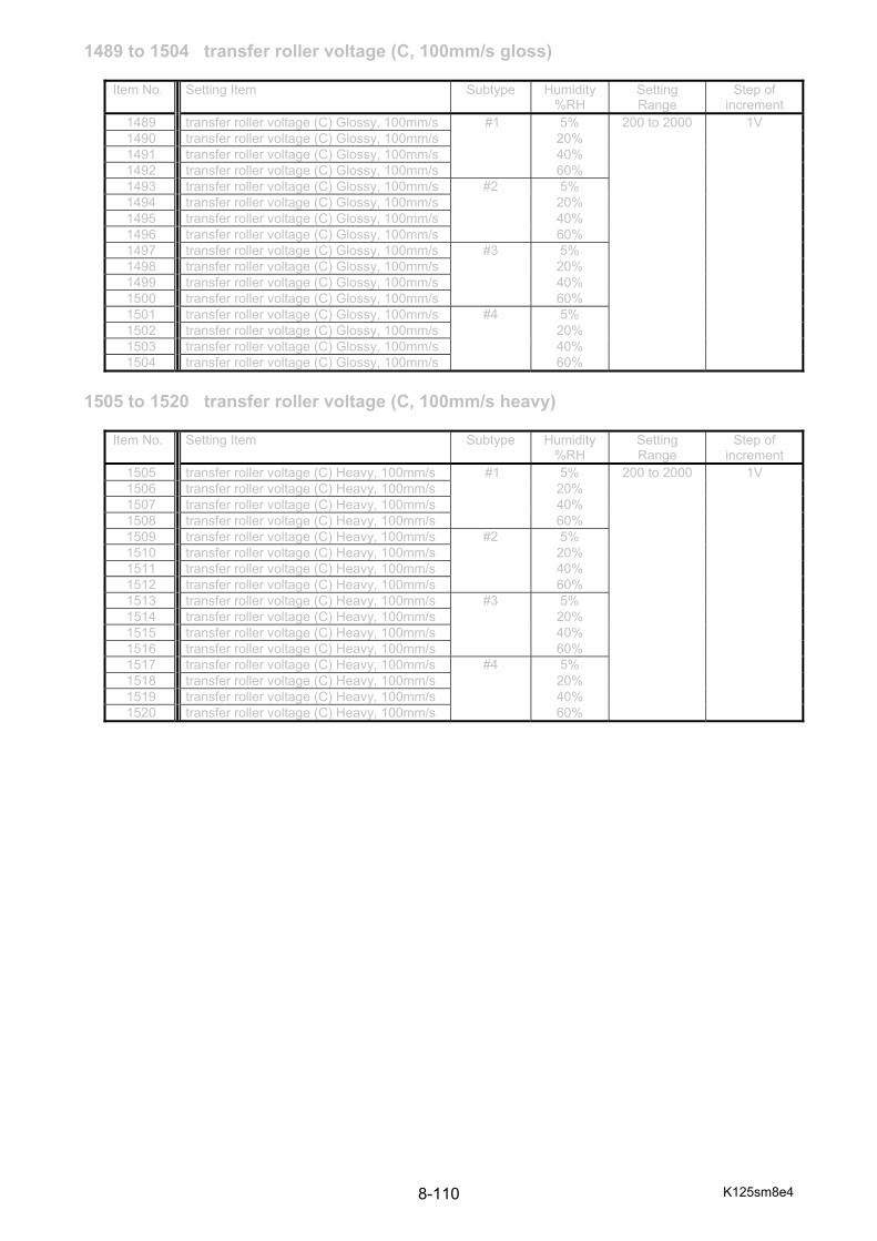
K125sm8e4 8-110
1489 to 1504 transfer roller voltage (C, 100mm/s gloss)
1505 to 1520 transfer roller voltage (C, 100mm/s heavy)
Item No. Setting Item Subtype Humidity%RH
Setting Range
Step of increment
1489 transfer roller voltage (C) Glossy, 100mm/s #1 5% 200 to 2000 1V 1490 transfer roller voltage (C) Glossy, 100mm/s 20% 1491 transfer roller voltage (C) Glossy, 100mm/s 40% 1492 transfer roller voltage (C) Glossy, 100mm/s 60% 1493 transfer roller voltage (C) Glossy, 100mm/s #2 5% 1494 transfer roller voltage (C) Glossy, 100mm/s 20% 1495 transfer roller voltage (C) Glossy, 100mm/s 40% 1496 transfer roller voltage (C) Glossy, 100mm/s 60% 1497 transfer roller voltage (C) Glossy, 100mm/s #3 5% 1498 transfer roller voltage (C) Glossy, 100mm/s 20% 1499 transfer roller voltage (C) Glossy, 100mm/s 40% 1500 transfer roller voltage (C) Glossy, 100mm/s 60% 1501 transfer roller voltage (C) Glossy, 100mm/s #4 5% 1502 transfer roller voltage (C) Glossy, 100mm/s 20% 1503 transfer roller voltage (C) Glossy, 100mm/s 40% 1504 transfer roller voltage (C) Glossy, 100mm/s 60%
Item No. Setting Item Subtype Humidity%RH
Setting Range
Step of increment
1505 transfer roller voltage (C) Heavy, 100mm/s #1 5% 200 to 2000 1V 1506 transfer roller voltage (C) Heavy, 100mm/s 20% 1507 transfer roller voltage (C) Heavy, 100mm/s 40% 1508 transfer roller voltage (C) Heavy, 100mm/s 60% 1509 transfer roller voltage (C) Heavy, 100mm/s #2 5% 1510 transfer roller voltage (C) Heavy, 100mm/s 20% 1511 transfer roller voltage (C) Heavy, 100mm/s 40% 1512 transfer roller voltage (C) Heavy, 100mm/s 60% 1513 transfer roller voltage (C) Heavy, 100mm/s #3 5% 1514 transfer roller voltage (C) Heavy, 100mm/s 20% 1515 transfer roller voltage (C) Heavy, 100mm/s 40% 1516 transfer roller voltage (C) Heavy, 100mm/s 60% 1517 transfer roller voltage (C) Heavy, 100mm/s #4 5% 1518 transfer roller voltage (C) Heavy, 100mm/s 20% 1519 transfer roller voltage (C) Heavy, 100mm/s 40% 1520 transfer roller voltage (C) Heavy, 100mm/s 60%

K125sm8e4 8-111
1521 to 1536 transfer roller voltage (C, 120mm/s plain) No.1521 to 1536 set the output voltage to the Transfer Roller for Cyan that is applied when the print speed is 120mm/sec. Increment or decrement of the value affects the density or degree of foggy background. Note that change of the value for only film related items (1553 to 1568) actually affects the print result. Items for all other medias are disabled, so nothing happens even if you change the value.
1537 to 1552 transfer roller voltage (C, 120mm/s tracing)
Item No. Setting Item Subtype Humidity%RH
Setting Range
Step of increment
1521 transfer roller voltage (C) Plain, 120mm/s #1 5% 200 to 2000 1V 1522 transfer roller voltage (C) Plain, 120mm/s 20% 1523 transfer roller voltage (C) Plain, 120mm/s 40% 1524 transfer roller voltage (C) Plain, 120mm/s 60% 1525 transfer roller voltage (C) Plain, 120mm/s #2 5% 1526 transfer roller voltage (C) Plain, 120mm/s 20% 1527 transfer roller voltage (C) Plain, 120mm/s 40% 1528 transfer roller voltage (C) Plain, 120mm/s 60% 1529 transfer roller voltage (C) Plain, 120mm/s #3 5% 1530 transfer roller voltage (C) Plain, 120mm/s 20% 1531 transfer roller voltage (C) Plain, 120mm/s 40% 1532 transfer roller voltage (C) Plain, 120mm/s 60% 1533 transfer roller voltage (C) Plain, 120mm/s #4 5% 1534 transfer roller voltage (C) Plain, 120mm/s 20% 1535 transfer roller voltage (C) Plain, 120mm/s 40% 1536 transfer roller voltage (C) Plain, 120mm/s 60%
Item No. Setting Item Subtype Humidity%RH
Setting Range
Step of increment
1537 transfer roller voltage (C) Tracing, 120mm/s #1 5% 200 to 2000 1V 1538 transfer roller voltage (C) Tracing, 120mm/s 20% 1539 transfer roller voltage (C) Tracing, 120mm/s 40% 1540 transfer roller voltage (C) Tracing, 120mm/s 60% 1541 transfer roller voltage (C) Tracing, 120mm/s #2 5% 1542 transfer roller voltage (C) Tracing, 120mm/s 20% 1543 transfer roller voltage (C) Tracing, 120mm/s 40% 1544 transfer roller voltage (C) Tracing, 120mm/s 60% 1545 transfer roller voltage (C) Tracing, 120mm/s #3 5% 1546 transfer roller voltage (C) Tracing, 120mm/s 20% 1547 transfer roller voltage (C) Tracing, 120mm/s 40% 1548 transfer roller voltage (C) Tracing, 120mm/s 60% 1549 transfer roller voltage (C) Tracing, 120mm/s #4 5% 1550 transfer roller voltage (C) Tracing, 120mm/s 20% 1551 transfer roller voltage (C) Tracing, 120mm/s 40% 1552 transfer roller voltage (C) Tracing, 120mm/s 60%
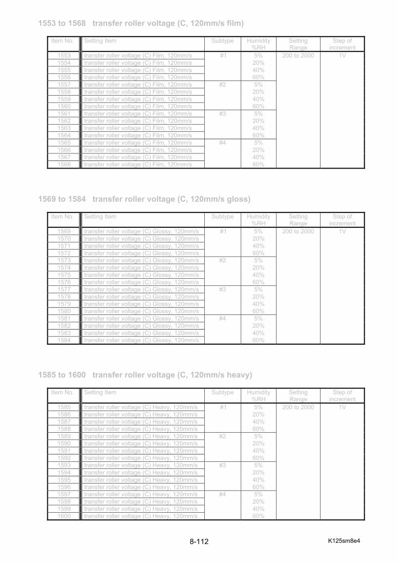
K125sm8e4 8-112
1553 to 1568 transfer roller voltage (C, 120mm/s film)
1569 to 1584 transfer roller voltage (C, 120mm/s gloss)
1585 to 1600 transfer roller voltage (C, 120mm/s heavy)
Item No. Setting Item Subtype Humidity%RH
Setting Range
Step of increment
1553 transfer roller voltage (C) Film, 120mm/s #1 5% 200 to 2000 1V 1554 transfer roller voltage (C) Film, 120mm/s 20% 1555 transfer roller voltage (C) Film, 120mm/s 40% 1556 transfer roller voltage (C) Film, 120mm/s 60% 1557 transfer roller voltage (C) Film, 120mm/s #2 5% 1558 transfer roller voltage (C) Film, 120mm/s 20% 1559 transfer roller voltage (C) Film, 120mm/s 40% 1560 transfer roller voltage (C) Film, 120mm/s 60% 1561 transfer roller voltage (C) Film, 120mm/s #3 5% 1562 transfer roller voltage (C) Film, 120mm/s 20% 1563 transfer roller voltage (C) Film, 120mm/s 40% 1564 transfer roller voltage (C) Film, 120mm/s 60% 1565 transfer roller voltage (C) Film, 120mm/s #4 5% 1566 transfer roller voltage (C) Film, 120mm/s 20% 1567 transfer roller voltage (C) Film, 120mm/s 40% 1568 transfer roller voltage (C) Film, 120mm/s 60%
Item No. Setting Item Subtype Humidity%RH
Setting Range
Step of increment
1569 transfer roller voltage (C) Glossy, 120mm/s #1 5% 200 to 2000 1V 1570 transfer roller voltage (C) Glossy, 120mm/s 20% 1571 transfer roller voltage (C) Glossy, 120mm/s 40% 1572 transfer roller voltage (C) Glossy, 120mm/s 60% 1573 transfer roller voltage (C) Glossy, 120mm/s #2 5% 1574 transfer roller voltage (C) Glossy, 120mm/s 20% 1575 transfer roller voltage (C) Glossy, 120mm/s 40% 1576 transfer roller voltage (C) Glossy, 120mm/s 60% 1577 transfer roller voltage (C) Glossy, 120mm/s #3 5% 1578 transfer roller voltage (C) Glossy, 120mm/s 20% 1579 transfer roller voltage (C) Glossy, 120mm/s 40% 1580 transfer roller voltage (C) Glossy, 120mm/s 60% 1581 transfer roller voltage (C) Glossy, 120mm/s #4 5% 1582 transfer roller voltage (C) Glossy, 120mm/s 20% 1583 transfer roller voltage (C) Glossy, 120mm/s 40% 1584 transfer roller voltage (C) Glossy, 120mm/s 60%
Item No. Setting Item Subtype Humidity%RH
Setting Range
Step of increment
1585 transfer roller voltage (C) Heavy, 120mm/s #1 5% 200 to 2000 1V 1586 transfer roller voltage (C) Heavy, 120mm/s 20% 1587 transfer roller voltage (C) Heavy, 120mm/s 40% 1588 transfer roller voltage (C) Heavy, 120mm/s 60% 1589 transfer roller voltage (C) Heavy, 120mm/s #2 5% 1590 transfer roller voltage (C) Heavy, 120mm/s 20% 1591 transfer roller voltage (C) Heavy, 120mm/s 40% 1592 transfer roller voltage (C) Heavy, 120mm/s 60% 1593 transfer roller voltage (C) Heavy, 120mm/s #3 5% 1594 transfer roller voltage (C) Heavy, 120mm/s 20% 1595 transfer roller voltage (C) Heavy, 120mm/s 40% 1596 transfer roller voltage (C) Heavy, 120mm/s 60% 1597 transfer roller voltage (C) Heavy, 120mm/s #4 5% 1598 transfer roller voltage (C) Heavy, 120mm/s 20% 1599 transfer roller voltage (C) Heavy, 120mm/s 40% 1600 transfer roller voltage (C) Heavy, 120mm/s 60%

K125sm8e4 8-113
1601 to 1616 transfer roller voltage (M, 60mm/s plain) No.1601 to 1616 set the output voltage to the Transfer Roller for Magenta that is applied when the print speed is 60mm/sec. Increment or decrement of the value affects the density or degree of foggy background. Note that change of the value for only film related items (1633 to 1648) actually affects the print result. Items for all other medias are disabled, so nothing happens even if you change the value.
1617 to 1632 transfer roller voltage (M, 60mm/s tracing)
Item No. Setting Item Subtype Humidity%RH
Setting Range
Step of increment
1601 transfer roller voltage (M) Plain, 60mm/s #1 5% 200 to 2000 1V 1602 transfer roller voltage (M) Plain, 60mm/s 20% 1603 transfer roller voltage (M) Plain, 60mm/s 40% 1604 transfer roller voltage (M) Plain, 60mm/s 60% 1605 transfer roller voltage (M) Plain, 60mm/s #2 5% 1606 transfer roller voltage (M) Plain, 60mm/s 20% 1607 transfer roller voltage (M) Plain, 60mm/s 40% 1608 transfer roller voltage (M) Plain, 60mm/s 60% 1609 transfer roller voltage (M) Plain, 60mm/s #3 5% 1610 transfer roller voltage (M) Plain, 60mm/s 20% 1611 transfer roller voltage (M) Plain, 60mm/s 40% 1612 transfer roller voltage (M) Plain, 60mm/s 60% 1613 transfer roller voltage (M) Plain, 60mm/s #4 5% 1614 transfer roller voltage (M) Plain, 60mm/s 20% 1615 transfer roller voltage (M) Plain, 60mm/s 40% 1616 transfer roller voltage (M) Plain, 60mm/s 60%
Item No. Setting Item Subtype Humidity%RH
Setting Range
Step of increment
1617 transfer roller voltage (M) Tracing, 60mm/s #1 5% 200 to 2000 1V 1618 transfer roller voltage (M) Tracing, 60mm/s 20% 1619 transfer roller voltage (M) Tracing, 60mm/s 40% 1620 transfer roller voltage (M) Tracing, 60mm/s 60% 1621 transfer roller voltage (M) Tracing, 60mm/s #2 5% 1622 transfer roller voltage (M) Tracing, 60mm/s 20% 1623 transfer roller voltage (M) Tracing, 60mm/s 40% 1624 transfer roller voltage (M) Tracing, 60mm/s 60% 1625 transfer roller voltage (M) Tracing, 60mm/s #3 5% 1626 transfer roller voltage (M) Tracing, 60mm/s 20% 1627 transfer roller voltage (M) Tracing, 60mm/s 40% 1628 transfer roller voltage (M) Tracing, 60mm/s 60% 1629 transfer roller voltage (M) Tracing, 60mm/s #4 5% 1630 transfer roller voltage (M) Tracing, 60mm/s 20% 1631 transfer roller voltage (M) Tracing, 60mm/s 40% 1632 transfer roller voltage (M) Tracing, 60mm/s 60%
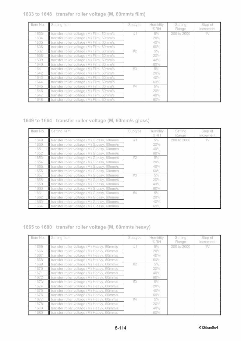
K125sm8e4 8-114
1633 to 1648 transfer roller voltage (M, 60mm/s film)
1649 to 1664 transfer roller voltage (M, 60mm/s gloss)
1665 to 1680 transfer roller voltage (M, 60mm/s heavy)
Item No. Setting Item Subtype Humidity%RH
Setting Range
Step of increment
1633 transfer roller voltage (M) Film, 60mm/s #1 5% 200 to 2000 1V 1634 transfer roller voltage (M) Film, 60mm/s 20% 1635 transfer roller voltage (M) Film, 60mm/s 40% 1636 transfer roller voltage (M) Film, 60mm/s 60% 1637 transfer roller voltage (M) Film, 60mm/s #2 5% 1638 transfer roller voltage (M) Film, 60mm/s 20% 1639 transfer roller voltage (M) Film, 60mm/s 40% 1640 transfer roller voltage (M) Film, 60mm/s 60% 1641 transfer roller voltage (M) Film, 60mm/s #3 5% 1642 transfer roller voltage (M) Film, 60mm/s 20% 1643 transfer roller voltage (M) Film, 60mm/s 40% 1644 transfer roller voltage (M) Film, 60mm/s 60% 1645 transfer roller voltage (M) Film, 60mm/s #4 5% 1646 transfer roller voltage (M) Film, 60mm/s 20% 1647 transfer roller voltage (M) Film, 60mm/s 40% 1648 transfer roller voltage (M) Film, 60mm/s 60%
Item No. Setting Item Subtype Humidity%RH
Setting Range
Step of increment
1649 transfer roller voltage (M) Glossy, 60mm/s #1 5% 200 to 2000 1V 1650 transfer roller voltage (M) Glossy, 60mm/s 20% 1651 transfer roller voltage (M) Glossy, 60mm/s 40% 1652 transfer roller voltage (M) Glossy, 60mm/s 60% 1653 transfer roller voltage (M) Glossy, 60mm/s #2 5% 1654 transfer roller voltage (M) Glossy, 60mm/s 20% 1655 transfer roller voltage (M) Glossy, 60mm/s 40% 1656 transfer roller voltage (M) Glossy, 60mm/s 60% 1657 transfer roller voltage (M) Glossy, 60mm/s #3 5% 1658 transfer roller voltage (M) Glossy, 60mm/s 20% 1659 transfer roller voltage (M) Glossy, 60mm/s 40% 1660 transfer roller voltage (M) Glossy, 60mm/s 60% 1661 transfer roller voltage (M) Glossy, 60mm/s #4 5% 1662 transfer roller voltage (M) Glossy, 60mm/s 20% 1663 transfer roller voltage (M) Glossy, 60mm/s 40% 1664 transfer roller voltage (M) Glossy, 60mm/s 60%
Item No. Setting Item Subtype Humidity%RH
Setting Range
Step of increment
1665 transfer roller voltage (M) Heavy, 60mm/s #1 5% 200 to 2000 1V 1666 transfer roller voltage (M) Heavy, 60mm/s 20% 1667 transfer roller voltage (M) Heavy, 60mm/s 40% 1668 transfer roller voltage (M) Heavy, 60mm/s 60% 1669 transfer roller voltage (M) Heavy, 60mm/s #2 5% 1670 transfer roller voltage (M) Heavy, 60mm/s 20% 1671 transfer roller voltage (M) Heavy, 60mm/s 40% 1672 transfer roller voltage (M) Heavy, 60mm/s 60% 1673 transfer roller voltage (M) Heavy, 60mm/s #3 5% 1674 transfer roller voltage (M) Heavy, 60mm/s 20% 1675 transfer roller voltage (M) Heavy, 60mm/s 40% 1676 transfer roller voltage (M) Heavy, 60mm/s 60% 1677 transfer roller voltage (M) Heavy, 60mm/s #4 5% 1678 transfer roller voltage (M) Heavy, 60mm/s 20% 1679 transfer roller voltage (M) Heavy, 60mm/s 40% 1680 transfer roller voltage (M) Heavy, 60mm/s 60%
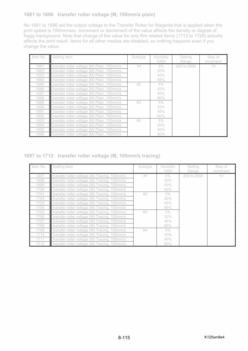
K125sm8e4 8-115
1681 to 1696 transfer roller voltage (M, 100mm/s plain) No.1681 to 1696 set the output voltage to the Transfer Roller for Magenta that is applied when the print speed is 100mm/sec. Increment or decrement of the value affects the density or degree of foggy background. Note that change of the value for only film related items (1713 to 1728) actually affects the print result. Items for all other medias are disabled, so nothing happens even if you change the value.
1697 to 1712 transfer roller voltage (M, 100mm/s tracing)
Item No. Setting Item Subtype Humidity%RH
Setting Range
Step of increment
1681 transfer roller voltage (M) Plain, 100mm/s #1 5% 200 to 2000 1V 1682 transfer roller voltage (M) Plain, 100mm/s 20% 1683 transfer roller voltage (M) Plain, 100mm/s 40% 1684 transfer roller voltage (M) Plain, 100mm/s 60% 1685 transfer roller voltage (M) Plain, 100mm/s #2 5% 1686 transfer roller voltage (M) Plain, 100mm/s 20% 1687 transfer roller voltage (M) Plain, 100mm/s 40% 1688 transfer roller voltage (M) Plain, 100mm/s 60% 1689 transfer roller voltage (M) Plain, 100mm/s #3 5% 1690 transfer roller voltage (M) Plain, 100mm/s 20% 1691 transfer roller voltage (M) Plain, 100mm/s 40% 1692 transfer roller voltage (M) Plain, 100mm/s 60% 1693 transfer roller voltage (M) Plain, 100mm/s #4 5% 1694 transfer roller voltage (M) Plain, 100mm/s 20% 1695 transfer roller voltage (M) Plain, 100mm/s 40% 1696 transfer roller voltage (M) Plain, 100mm/s 60%
Item No. Setting Item Subtype Humidity %RH
Setting Range
Step of increment
1697 transfer roller voltage (M) Tracing, 100mm/s #1 5% 200 to 2000 1V 1698 transfer roller voltage (M) Tracing, 100mm/s 20% 1699 transfer roller voltage (M) Tracing, 100mm/s 40% 1700 transfer roller voltage (M) Tracing, 100mm/s 60% 1701 transfer roller voltage (M) Tracing, 100mm/s #2 5% 1702 transfer roller voltage (M) Tracing, 100mm/s 20% 1703 transfer roller voltage (M) Tracing, 100mm/s 40% 1704 transfer roller voltage (M) Tracing, 100mm/s 60% 1705 transfer roller voltage (M) Tracing, 100mm/s #3 5% 1706 transfer roller voltage (M) Tracing, 100mm/s 20% 1707 transfer roller voltage (M) Tracing, 100mm/s 40% 1708 transfer roller voltage (M) Tracing, 100mm/s 60% 1709 transfer roller voltage (M) Tracing, 100mm/s #4 5% 1710 transfer roller voltage (M) Tracing, 100mm/s 20% 1711 transfer roller voltage (M) Tracing, 100mm/s 40% 1712 transfer roller voltage (M) Tracing, 100mm/s 60%

K125sm8e4 8-116
1713 to 1728 transfer roller voltage (M, 100mm/s film)
1729 to 1744 transfer roller voltage (M, 100mm/s gloss)
1745 to 1760 transfer roller voltage (M, 100mm/s heavy)
Item No. Setting Item Subtype Humidity%RH
Setting Range
Step of increment
1713 transfer roller voltage (M) Film, 100mm/s #1 5% 200 to 2000 1V 1714 transfer roller voltage (M) Film, 100mm/s 20% 1715 transfer roller voltage (M) Film, 100mm/s 40% 1716 transfer roller voltage (M) Film, 100mm/s 60% 1717 transfer roller voltage (M) Film, 100mm/s #2 5% 1718 transfer roller voltage (M) Film, 100mm/s 20% 1719 transfer roller voltage (M) Film, 100mm/s 40% 1720 transfer roller voltage (M) Film, 100mm/s 60% 1721 transfer roller voltage (M) Film, 100mm/s #3 5% 1722 transfer roller voltage (M) Film, 100mm/s 20% 1723 transfer roller voltage (M) Film, 100mm/s 40% 1724 transfer roller voltage (M) Film, 100mm/s 60% 1725 transfer roller voltage (M) Film, 100mm/s #4 5% 1726 transfer roller voltage (M) Film, 100mm/s 20% 1727 transfer roller voltage (M) Film, 100mm/s 40% 1728 transfer roller voltage (M) Film, 100mm/s 60%
Item No. Setting Item Subtype Humidity%RH
Setting Range
Step of increment
1729 transfer roller voltage (M) Glossy, 100mm/s #1 5% 200 to 2000 1V 1730 transfer roller voltage (M) Glossy, 100mm/s 20% 1731 transfer roller voltage (M) Glossy, 100mm/s 40% 1732 transfer roller voltage (M) Glossy, 100mm/s 60% 1733 transfer roller voltage (M) Glossy, 100mm/s #2 5% 1734 transfer roller voltage (M) Glossy, 100mm/s 20% 1735 transfer roller voltage (M) Glossy, 100mm/s 40% 1736 transfer roller voltage (M) Glossy, 100mm/s 60% 1737 transfer roller voltage (M) Glossy, 100mm/s #3 5% 1738 transfer roller voltage (M) Glossy, 100mm/s 20% 1739 transfer roller voltage (M) Glossy, 100mm/s 40% 1740 transfer roller voltage (M) Glossy, 100mm/s 60% 1741 transfer roller voltage (M) Glossy, 100mm/s #4 5% 1742 transfer roller voltage (M) Glossy, 100mm/s 20% 1743 transfer roller voltage (M) Glossy, 100mm/s 40% 1744 transfer roller voltage (M) Glossy, 100mm/s 60%
Item No. Setting Item Subtype Humidity%RH
Setting Range
Step of increment
1745 transfer roller voltage (M) Heavy, 100mm/s #1 5% 200 to 2000 1V 1746 transfer roller voltage (M) Heavy, 100mm/s 20% 1747 transfer roller voltage (M) Heavy, 100mm/s 40% 1748 transfer roller voltage (M) Heavy, 100mm/s 60% 1749 transfer roller voltage (M) Heavy, 100mm/s #2 5% 1750 transfer roller voltage (M) Heavy, 100mm/s 20% 1751 transfer roller voltage (M) Heavy, 100mm/s 40% 1752 transfer roller voltage (M) Heavy, 100mm/s 60% 1753 transfer roller voltage (M) Heavy, 100mm/s #3 5% 1754 transfer roller voltage (M) Heavy, 100mm/s 20% 1755 transfer roller voltage (M) Heavy, 100mm/s 40% 1756 transfer roller voltage (M) Heavy, 100mm/s 60% 1757 transfer roller voltage (M) Heavy, 100mm/s #4 5% 1758 transfer roller voltage (M) Heavy, 100mm/s 20% 1759 transfer roller voltage (M) Heavy, 100mm/s 40% 1760 transfer roller voltage (M) Heavy, 100mm/s 60%

K125sm8e4 8-117
1761 to 1776 transfer roller voltage (M, 120mm/s plain) No.1761 to 1776 set the output voltage to the Transfer Roller for Magenta that is applied when the print speed is 120mm/sec. Increment or decrement of the value affects the density or degree of foggy background. Note that change of the value for only film related items (1793 to 1808) actually affects the print result. Items for all other medias are disabled, so nothing happens even if you change the value.
1777 to 1792 transfer roller voltage (M, 120mm/s tracing)
Item No. Setting Item Subtype Humidity%RH
Setting Range
Step of increment
1761 transfer roller voltage (M) Plain, 120mm/s #1 5% 200 to 2000 1V 1762 transfer roller voltage (M) Plain, 120mm/s 20% 1763 transfer roller voltage (M) Plain, 120mm/s 40% 1764 transfer roller voltage (M) Plain, 120mm/s 60% 1765 transfer roller voltage (M) Plain, 120mm/s #2 5% 1766 transfer roller voltage (M) Plain, 120mm/s 20% 1767 transfer roller voltage (M) Plain, 120mm/s 40% 1768 transfer roller voltage (M) Plain, 120mm/s 60% 1769 transfer roller voltage (M) Plain, 120mm/s #3 5% 1770 transfer roller voltage (M) Plain, 120mm/s 20% 1771 transfer roller voltage (M) Plain, 120mm/s 40% 1772 transfer roller voltage (M) Plain, 120mm/s 60% 1773 transfer roller voltage (M) Plain, 120mm/s #4 5% 1774 transfer roller voltage (M) Plain, 120mm/s 20% 1775 transfer roller voltage (M) Plain, 120mm/s 40% 1776 transfer roller voltage (M) Plain, 120mm/s 60%
Item No. Setting Item Subtype Humidity %RH
Setting Range
Step of increment
1777 transfer roller voltage (M) Tracing, 120mm/s #1 5% 200 to 2000 1V 1778 transfer roller voltage (M) Tracing, 120mm/s 20% 1779 transfer roller voltage (M) Tracing, 120mm/s 40% 1780 transfer roller voltage (M) Tracing, 120mm/s 60% 1781 transfer roller voltage (M) Tracing, 120mm/s #2 5% 1782 transfer roller voltage (M) Tracing, 120mm/s 20% 1783 transfer roller voltage (M) Tracing, 120mm/s 40% 1784 transfer roller voltage (M) Tracing, 120mm/s 60% 1785 transfer roller voltage (M) Tracing, 120mm/s #3 5% 1786 transfer roller voltage (M) Tracing, 120mm/s 20% 1787 transfer roller voltage (M) Tracing, 120mm/s 40% 1788 transfer roller voltage (M) Tracing, 120mm/s 60% 1789 transfer roller voltage (M) Tracing, 120mm/s #4 5% 1790 transfer roller voltage (M) Tracing, 120mm/s 20% 1791 transfer roller voltage (M) Tracing, 120mm/s 40% 1792 transfer roller voltage (M) Tracing, 120mm/s 60%

K125sm8e4 8-118
1793 to 1808 transfer roller voltage (M, 120mm/s film)
1809 to 1824 transfer roller voltage (M, 120mm/s gloss)
1825 to 1840 transfer roller voltage (M, 120mm/s heavy)
Item No. Setting Item Subtype Humidity%RH
Setting Range
Step of increment
1793 transfer roller voltage (M) Film, 120mm/s #1 5% 200 to 2000 1V 1794 transfer roller voltage (M) Film, 120mm/s 20% 1795 transfer roller voltage (M) Film, 120mm/s 40% 1796 transfer roller voltage (M) Film, 120mm/s 60% 1797 transfer roller voltage (M) Film, 120mm/s #2 5% 1798 transfer roller voltage (M) Film, 120mm/s 20% 1799 transfer roller voltage (M) Film, 120mm/s 40% 1800 transfer roller voltage (M) Film, 120mm/s 60% 1801 transfer roller voltage (M) Film, 120mm/s #3 5% 1802 transfer roller voltage (M) Film, 120mm/s 20% 1803 transfer roller voltage (M) Film, 120mm/s 40% 1804 transfer roller voltage (M) Film, 120mm/s 60% 1805 transfer roller voltage (M) Film, 120mm/s #4 5% 1806 transfer roller voltage (M) Film, 120mm/s 20% 1807 transfer roller voltage (M) Film, 120mm/s 40% 1808 transfer roller voltage (M) Film, 120mm/s 60%
Item No. Setting Item Subtype Humidity%RH
Setting Range
Step of increment
1809 transfer roller voltage (M) Glossy, 120mm/s #1 5% 200 to 2000 1V 1810 transfer roller voltage (M) Glossy, 120mm/s 20% 1811 transfer roller voltage (M) Glossy, 120mm/s 40% 1812 transfer roller voltage (M) Glossy, 120mm/s 60% 1813 transfer roller voltage (M) Glossy, 120mm/s #2 5% 1814 transfer roller voltage (M) Glossy, 120mm/s 20% 1815 transfer roller voltage (M) Glossy, 120mm/s 40% 1816 transfer roller voltage (M) Glossy, 120mm/s 60% 1817 transfer roller voltage (M) Glossy, 120mm/s #3 5% 1818 transfer roller voltage (M) Glossy, 120mm/s 20% 1819 transfer roller voltage (M) Glossy, 120mm/s 40% 1820 transfer roller voltage (M) Glossy, 120mm/s 60% 1821 transfer roller voltage (M) Glossy, 120mm/s #4 5% 1822 transfer roller voltage (M) Glossy, 120mm/s 20% 1823 transfer roller voltage (M) Glossy, 120mm/s 40% 1824 transfer roller voltage (M) Glossy, 120mm/s 60%
Item No. Setting Item Subtype Humidity%RH
Setting Range
Step of increment
1825 transfer roller voltage (M) Heavy, 120mm/s #1 5% 200 to 2000 1V 1826 transfer roller voltage (M) Heavy, 120mm/s 20% 1827 transfer roller voltage (M) Heavy, 120mm/s 40% 1828 transfer roller voltage (M) Heavy, 120mm/s 60% 1829 transfer roller voltage (M) Heavy, 120mm/s #2 5% 1830 transfer roller voltage (M) Heavy, 120mm/s 20% 1831 transfer roller voltage (M) Heavy, 120mm/s 40% 1832 transfer roller voltage (M) Heavy, 120mm/s 60% 1833 transfer roller voltage (M) Heavy, 120mm/s #3 5% 1834 transfer roller voltage (M) Heavy, 120mm/s 20% 1835 transfer roller voltage (M) Heavy, 120mm/s 40% 1836 transfer roller voltage (M) Heavy, 120mm/s 60% 1837 transfer roller voltage (M) Heavy, 120mm/s #4 5% 1838 transfer roller voltage (M) Heavy, 120mm/s 20% 1839 transfer roller voltage (M) Heavy, 120mm/s 40% 1840 transfer roller voltage (M) Heavy, 120mm/s 60%

K125sm8e4 8-119
1841 to 1856 transfer roller voltage (Y, 60Ym/s plain) No.1841 to 1856 set the output voltage to the Transfer Roller for Yellow that is applied when the print speed is 60mm/sec. Increment or decrement of the value affects the density or degree of foggy background. Note that change of the value for only film related items (1873 to 1888) actually affects the print result. Items for all other medias are disabled, so nothing happens even if you change the value.
1857 to 1872 transfer roller voltage (Y, 60mm/s tracing)
Item No. Setting Item Subtype Humidity%RH
Setting Range
Step of increment
1841 transfer roller voltage (Y) Plain, 60mm/s #1 5% 200 to 2000 1V 1842 transfer roller voltage (Y) Plain, 60mm/s 20% 1843 transfer roller voltage (Y) Plain, 60mm/s 40% 1844 transfer roller voltage (Y) Plain, 60mm/s 60% 1845 transfer roller voltage (Y) Plain, 60mm/s #2 5% 1846 transfer roller voltage (Y) Plain, 60mm/s 20% 1847 transfer roller voltage (Y) Plain, 60mm/s 40% 1848 transfer roller voltage (Y) Plain, 60mm/s 60% 1849 transfer roller voltage (Y) Plain, 60mm/s #3 5% 1850 transfer roller voltage (Y) Plain, 60mm/s 20% 1851 transfer roller voltage (Y) Plain, 60mm/s 40% 1852 transfer roller voltage (Y) Plain, 60mm/s 60% 1853 transfer roller voltage (Y) Plain, 60mm/s #4 5% 1854 transfer roller voltage (Y) Plain, 60mm/s 20% 1855 transfer roller voltage (Y) Plain, 60mm/s 40% 1856 transfer roller voltage (Y) Plain, 60mm/s 60%
Item No. Setting Item Subtype Humidity%RH
Setting Range
Step of increment
1857 transfer roller voltage (Y) Tracing, 60mm/s #1 5% 200 to 2000 1V 1858 transfer roller voltage (Y) Tracing, 60mm/s 20% 1859 transfer roller voltage (Y) Tracing, 60mm/s 40% 1860 transfer roller voltage (Y) Tracing, 60mm/s 60% 1861 transfer roller voltage (Y) Tracing, 60mm/s #2 5% 1862 transfer roller voltage (Y) Tracing, 60mm/s 20% 1863 transfer roller voltage (Y) Tracing, 60mm/s 40% 1864 transfer roller voltage (Y) Tracing, 60mm/s 60% 1865 transfer roller voltage (Y) Tracing, 60mm/s #3 5% 1866 transfer roller voltage (Y) Tracing, 60mm/s 20% 1867 transfer roller voltage (Y) Tracing, 60mm/s 40% 1868 transfer roller voltage (Y) Tracing, 60mm/s 60% 1869 transfer roller voltage (Y) Tracing, 60mm/s #4 5% 1870 transfer roller voltage (Y) Tracing, 60mm/s 20% 1871 transfer roller voltage (Y) Tracing, 60mm/s 40% 1872 transfer roller voltage (Y) Tracing, 60mm/s 60%
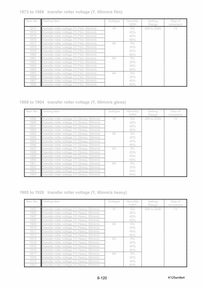
K125sm8e4 8-120
1873 to 1888 transfer roller voltage (Y, 60mm/s film)
1889 to 1904 transfer roller voltage (Y, 60mm/s gloss)
1905 to 1920 transfer roller voltage (Y, 60mm/s heavy)
Item No. Setting Item Subtype Humidity%RH
Setting Range
Step of increment
1873 transfer roller voltage (Y) Film, 60mm/s #1 5% 200 to 2000 1V 1874 transfer roller voltage (Y) Film, 60mm/s 20% 1875 transfer roller voltage (Y) Film, 60mm/s 40% 1876 transfer roller voltage (Y) Film, 60mm/s 60% 1877 transfer roller voltage (Y) Film, 60mm/s #2 5% 1878 transfer roller voltage (Y) Film, 60mm/s 20% 1879 transfer roller voltage (Y) Film, 60mm/s 40% 1880 transfer roller voltage (Y) Film, 60mm/s 60% 1881 transfer roller voltage (Y) Film, 60mm/s #3 5% 1882 transfer roller voltage (Y) Film, 60mm/s 20% 1883 transfer roller voltage (Y) Film, 60mm/s 40% 1884 transfer roller voltage (Y) Film, 60mm/s 60% 1885 transfer roller voltage (Y) Film, 60mm/s #4 5% 1886 transfer roller voltage (Y) Film, 60mm/s 20% 1887 transfer roller voltage (Y) Film, 60mm/s 40% 1888 transfer roller voltage (Y) Film, 60mm/s 60%
Item No. Setting Item Subtype Humidity%RH
Setting Range
Step of increment
1889 transfer roller voltage (Y) Glossy, 60mm/s #1 5% 200 to 2000 1V 1890 transfer roller voltage (Y) Glossy, 60mm/s 20% 1891 transfer roller voltage (Y) Glossy, 60mm/s 40% 1892 transfer roller voltage (Y) Glossy, 60mm/s 60% 1893 transfer roller voltage (Y) Glossy, 60mm/s #2 5% 1894 transfer roller voltage (Y) Glossy, 60mm/s 20% 1895 transfer roller voltage (Y) Glossy, 60mm/s 40% 1896 transfer roller voltage (Y) Glossy, 60mm/s 60% 1897 transfer roller voltage (Y) Glossy, 60mm/s #3 5% 1898 transfer roller voltage (Y) Glossy, 60mm/s 20% 1899 transfer roller voltage (Y) Glossy, 60mm/s 40% 1900 transfer roller voltage (Y) Glossy, 60mm/s 60% 1901 transfer roller voltage (Y) Glossy, 60mm/s #4 5% 1902 transfer roller voltage (Y) Glossy, 60mm/s 20% 1903 transfer roller voltage (Y) Glossy, 60mm/s 40% 1904 transfer roller voltage (Y) Glossy, 60mm/s 60%
Item No. Setting Item Subtype Humidity%RH
Setting Range
Step of increment
1905 transfer roller voltage (Y) Heavy, 60mm/s #1 5% 200 to 2000 1V 1906 transfer roller voltage (Y) Heavy, 60mm/s 20% 1907 transfer roller voltage (Y) Heavy, 60mm/s 40% 1908 transfer roller voltage (Y) Heavy, 60mm/s 60% 1909 transfer roller voltage (Y) Heavy, 60mm/s #2 5% 1910 transfer roller voltage (Y) Heavy, 60mm/s 20% 1911 transfer roller voltage (Y) Heavy, 60mm/s 40% 1912 transfer roller voltage (Y) Heavy, 60mm/s 60% 1913 transfer roller voltage (Y) Heavy, 60mm/s #3 5% 1914 transfer roller voltage (Y) Heavy, 60mm/s 20% 1915 transfer roller voltage (Y) Heavy, 60mm/s 40% 1916 transfer roller voltage (Y) Heavy, 60mm/s 60% 1917 transfer roller voltage (Y) Heavy, 60mm/s #4 5% 1918 transfer roller voltage (Y) Heavy, 60mm/s 20% 1919 transfer roller voltage (Y) Heavy, 60mm/s 40% 1920 transfer roller voltage (Y) Heavy, 60mm/s 60%

K125sm8e4 8-121
1921 to 1936 transfer roller voltage (Y, 100mm/s plain) No.1921 to 1936 set the output voltage to the Transfer Roller for Yellow that is applied when the print speed is 100mm/sec. Increment or decrement of the value affects the density or degree of foggy background. Note that change of the value for only film related items (1953 to 1968) actually affects the print result. Items for all other medias are disabled, so nothing happens even if you change the value.
1937 to 1952 transfer roller voltage (Y, 100mm/s tracing)
Item No. Setting Item Subtype Humidity%RH
Setting Range
Step of increment
1921 transfer roller voltage (Y) Plain, 100mm/s #1 5% 200 to 2000 1V 1922 transfer roller voltage (Y) Plain, 100mm/s 20% 1923 transfer roller voltage (Y) Plain, 100mm/s 40% 1924 transfer roller voltage (Y) Plain, 100mm/s 60% 1925 transfer roller voltage (Y) Plain, 100mm/s #2 5% 1926 transfer roller voltage (Y) Plain, 100mm/s 20% 1927 transfer roller voltage (Y) Plain, 100mm/s 40% 1928 transfer roller voltage (Y) Plain, 100mm/s 60% 1929 transfer roller voltage (Y) Plain, 100mm/s #3 5% 1930 transfer roller voltage (Y) Plain, 100mm/s 20% 1931 transfer roller voltage (Y) Plain, 100mm/s 40% 1932 transfer roller voltage (Y) Plain, 100mm/s 60% 1933 transfer roller voltage (Y) Plain, 100mm/s #4 5% 1934 transfer roller voltage (Y) Plain, 100mm/s 20% 1935 transfer roller voltage (Y) Plain, 100mm/s 40% 1936 transfer roller voltage (Y) Plain, 100mm/s 60%
Item No. Setting Item Subtype Humidity %RH
Setting Range
Step of increment
1937 transfer roller voltage (Y) Tracing, 100mm/s #1 5% 200 to 2000 1V 1938 transfer roller voltage (Y) Tracing, 100mm/s 20% 1939 transfer roller voltage (Y) Tracing, 100mm/s 40% 1940 transfer roller voltage (Y) Tracing, 100mm/s 60% 1941 transfer roller voltage (Y) Tracing, 100mm/s #2 5% 1942 transfer roller voltage (Y) Tracing, 100mm/s 20% 1943 transfer roller voltage (Y) Tracing, 100mm/s 40% 1944 transfer roller voltage (Y) Tracing, 100mm/s 60% 1945 transfer roller voltage (Y) Tracing, 100mm/s #3 5% 1946 transfer roller voltage (Y) Tracing, 100mm/s 20% 1947 transfer roller voltage (Y) Tracing, 100mm/s 40% 1948 transfer roller voltage (Y) Tracing, 100mm/s 60% 1949 transfer roller voltage (Y) Tracing, 100mm/s #4 5% 1950 transfer roller voltage (Y) Tracing, 100mm/s 20% 1951 transfer roller voltage (Y) Tracing, 100mm/s 40% 1952 transfer roller voltage (Y) Tracing, 100mm/s 60%

K125sm8e4 8-122
1953 to 1968 transfer roller voltage (Y, 100mm/s film)
1969 to 1984 transfer roller voltage (Y, 100mm/s gloss)
1985 to 2000 transfer roller voltage (Y, 100mm/s heavy)
Item No. Setting Item Subtype Humidity%RH
Setting Range
Step of increment
1953 transfer roller voltage (Y) Film, 100mm/s #1 5% 200 to 2000 1V 1954 transfer roller voltage (Y) Film, 100mm/s 20% 1955 transfer roller voltage (Y) Film, 100mm/s 40% 1956 transfer roller voltage (Y) Film, 100mm/s 60% 1957 transfer roller voltage (Y) Film, 100mm/s #2 5% 1958 transfer roller voltage (Y) Film, 100mm/s 20% 1959 transfer roller voltage (Y) Film, 100mm/s 40% 1960 transfer roller voltage (Y) Film, 100mm/s 60% 1961 transfer roller voltage (Y) Film, 100mm/s #3 5% 1962 transfer roller voltage (Y) Film, 100mm/s 20% 1963 transfer roller voltage (Y) Film, 100mm/s 40% 1964 transfer roller voltage (Y) Film, 100mm/s 60% 1965 transfer roller voltage (Y) Film, 100mm/s #4 5% 1966 transfer roller voltage (Y) Film, 100mm/s 20% 1967 transfer roller voltage (Y) Film, 100mm/s 40% 1968 transfer roller voltage (Y) Film, 100mm/s 60%
Item No. Setting Item Subtype Humidity%RH
Setting Range
Step of increment
1969 transfer roller voltage (Y) Glossy, 100mm/s #1 5% 200 to 2000 1V 1970 transfer roller voltage (Y) Glossy, 100mm/s 20% 1971 transfer roller voltage (Y) Glossy, 100mm/s 40% 1972 transfer roller voltage (Y) Glossy, 100mm/s 60% 1973 transfer roller voltage (Y) Glossy, 100mm/s #2 5% 1974 transfer roller voltage (Y) Glossy, 100mm/s 20% 1975 transfer roller voltage (Y) Glossy, 100mm/s 40% 1976 transfer roller voltage (Y) Glossy, 100mm/s 60% 1977 transfer roller voltage (Y) Glossy, 100mm/s #3 5% 1978 transfer roller voltage (Y) Glossy, 100mm/s 20% 1979 transfer roller voltage (Y) Glossy, 100mm/s 40% 1980 transfer roller voltage (Y) Glossy, 100mm/s 60% 1981 transfer roller voltage (Y) Glossy, 100mm/s #4 5% 1982 transfer roller voltage (Y) Glossy, 100mm/s 20% 1983 transfer roller voltage (Y) Glossy, 100mm/s 40% 1984 transfer roller voltage (Y) Glossy, 100mm/s 60%
Item No. Setting Item Subtype Humidity%RH
Setting Range
Step of increment
1985 transfer roller voltage (Y) Heavy, 100mm/s #1 5% 200 to 2000 1V 1986 transfer roller voltage (Y) Heavy, 100mm/s 20% 1987 transfer roller voltage (Y) Heavy, 100mm/s 40% 1988 transfer roller voltage (Y) Heavy, 100mm/s 60% 1989 transfer roller voltage (Y) Heavy, 100mm/s #2 5% 1990 transfer roller voltage (Y) Heavy, 100mm/s 20% 1991 transfer roller voltage (Y) Heavy, 100mm/s 40% 1992 transfer roller voltage (Y) Heavy, 100mm/s 60% 1993 transfer roller voltage (Y) Heavy, 100mm/s #3 5% 1994 transfer roller voltage (Y) Heavy, 100mm/s 20% 1995 transfer roller voltage (Y) Heavy, 100mm/s 40% 1996 transfer roller voltage (Y) Heavy, 100mm/s 60% 1997 transfer roller voltage (Y) Heavy, 100mm/s #4 5% 1998 transfer roller voltage (Y) Heavy, 100mm/s 20% 1999 transfer roller voltage (Y) Heavy, 100mm/s 40% 2000 transfer roller voltage (Y) Heavy, 100mm/s 60%
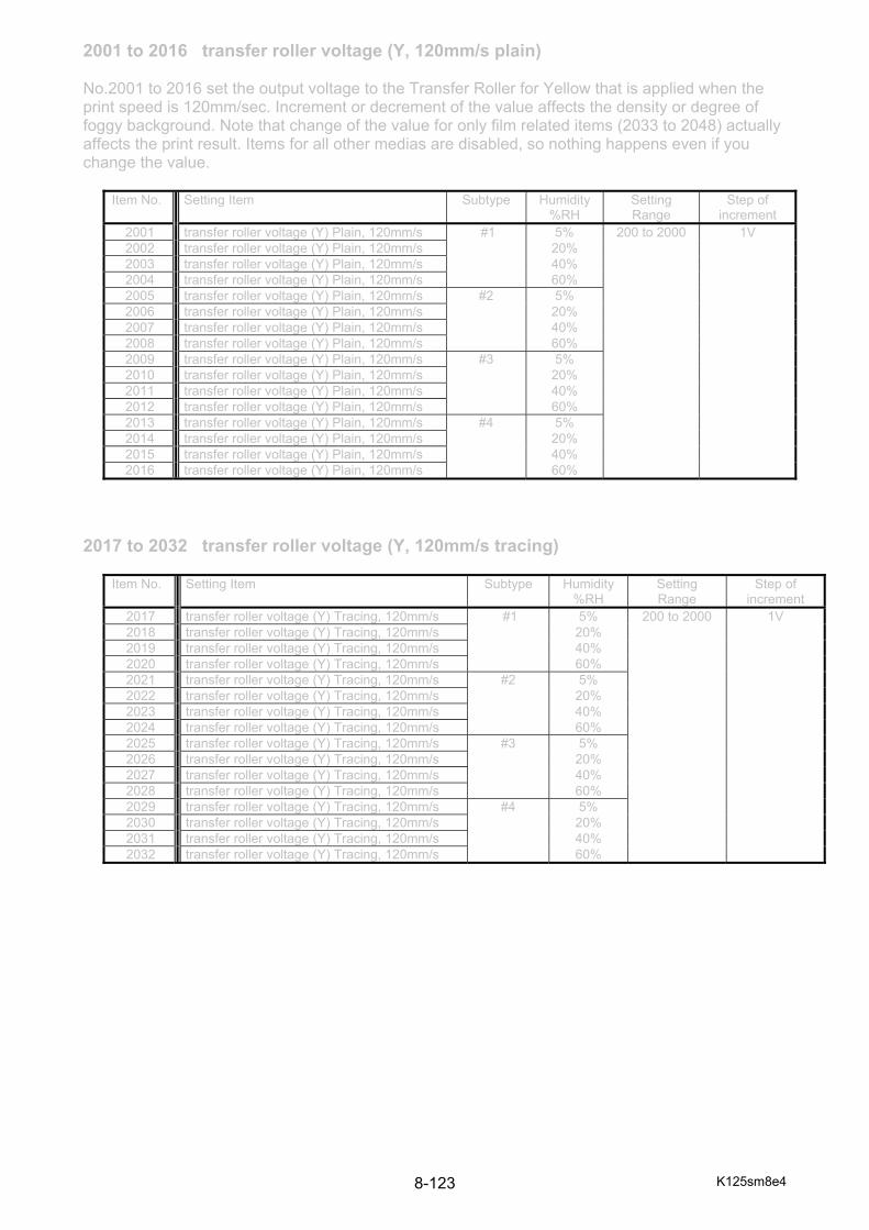
K125sm8e4 8-123
2001 to 2016 transfer roller voltage (Y, 120mm/s plain) No.2001 to 2016 set the output voltage to the Transfer Roller for Yellow that is applied when the print speed is 120mm/sec. Increment or decrement of the value affects the density or degree of foggy background. Note that change of the value for only film related items (2033 to 2048) actually affects the print result. Items for all other medias are disabled, so nothing happens even if you change the value.
2017 to 2032 transfer roller voltage (Y, 120mm/s tracing)
Item No. Setting Item Subtype Humidity%RH
Setting Range
Step of increment
2001 transfer roller voltage (Y) Plain, 120mm/s #1 5% 200 to 2000 1V 2002 transfer roller voltage (Y) Plain, 120mm/s 20% 2003 transfer roller voltage (Y) Plain, 120mm/s 40% 2004 transfer roller voltage (Y) Plain, 120mm/s 60% 2005 transfer roller voltage (Y) Plain, 120mm/s #2 5% 2006 transfer roller voltage (Y) Plain, 120mm/s 20% 2007 transfer roller voltage (Y) Plain, 120mm/s 40% 2008 transfer roller voltage (Y) Plain, 120mm/s 60% 2009 transfer roller voltage (Y) Plain, 120mm/s #3 5% 2010 transfer roller voltage (Y) Plain, 120mm/s 20% 2011 transfer roller voltage (Y) Plain, 120mm/s 40% 2012 transfer roller voltage (Y) Plain, 120mm/s 60% 2013 transfer roller voltage (Y) Plain, 120mm/s #4 5% 2014 transfer roller voltage (Y) Plain, 120mm/s 20% 2015 transfer roller voltage (Y) Plain, 120mm/s 40% 2016 transfer roller voltage (Y) Plain, 120mm/s 60%
Item No. Setting Item Subtype Humidity %RH
Setting Range
Step of increment
2017 transfer roller voltage (Y) Tracing, 120mm/s #1 5% 200 to 2000 1V 2018 transfer roller voltage (Y) Tracing, 120mm/s 20% 2019 transfer roller voltage (Y) Tracing, 120mm/s 40% 2020 transfer roller voltage (Y) Tracing, 120mm/s 60% 2021 transfer roller voltage (Y) Tracing, 120mm/s #2 5% 2022 transfer roller voltage (Y) Tracing, 120mm/s 20% 2023 transfer roller voltage (Y) Tracing, 120mm/s 40% 2024 transfer roller voltage (Y) Tracing, 120mm/s 60% 2025 transfer roller voltage (Y) Tracing, 120mm/s #3 5% 2026 transfer roller voltage (Y) Tracing, 120mm/s 20% 2027 transfer roller voltage (Y) Tracing, 120mm/s 40% 2028 transfer roller voltage (Y) Tracing, 120mm/s 60% 2029 transfer roller voltage (Y) Tracing, 120mm/s #4 5% 2030 transfer roller voltage (Y) Tracing, 120mm/s 20% 2031 transfer roller voltage (Y) Tracing, 120mm/s 40% 2032 transfer roller voltage (Y) Tracing, 120mm/s 60%

K125sm8e4 8-124
2033 to 2048 transfer roller voltage (Y, 120mm/s film)
2049 to 2064 transfer roller voltage (Y, 120mm/s gloss)
2065 to 2080 transfer roller voltage (Y, 120mm/s heavy)
Item No. Setting Item Subtype Humidity%RH
Setting Range
Step of increment
2033 transfer roller voltage (Y) Film, 120mm/s #1 5% 200 to 2000 1V 2034 transfer roller voltage (Y) Film, 120mm/s 20% 2035 transfer roller voltage (Y) Film, 120mm/s 40% 2036 transfer roller voltage (Y) Film, 120mm/s 60% 2037 transfer roller voltage (Y) Film, 120mm/s #2 5% 2038 transfer roller voltage (Y) Film, 120mm/s 20% 2039 transfer roller voltage (Y) Film, 120mm/s 40% 2040 transfer roller voltage (Y) Film, 120mm/s 60% 2041 transfer roller voltage (Y) Film, 120mm/s #3 5% 2042 transfer roller voltage (Y) Film, 120mm/s 20% 2043 transfer roller voltage (Y) Film, 120mm/s 40% 2044 transfer roller voltage (Y) Film, 120mm/s 60% 2045 transfer roller voltage (Y) Film, 120mm/s #4 5% 2046 transfer roller voltage (Y) Film, 120mm/s 20% 2047 transfer roller voltage (Y) Film, 120mm/s 40% 2048 transfer roller voltage (Y) Film, 120mm/s 60%
Item No. Setting Item Subtype Humidity%RH
Setting Range
Step of increment
2049 transfer roller voltage (Y) Glossy, 120mm/s #1 5% 200 to 2000 1V 2050 transfer roller voltage (Y) Glossy, 120mm/s 20% 2051 transfer roller voltage (Y) Glossy, 120mm/s 40% 2052 transfer roller voltage (Y) Glossy, 120mm/s 60% 2053 transfer roller voltage (Y) Glossy, 120mm/s #2 5% 2054 transfer roller voltage (Y) Glossy, 120mm/s 20% 2055 transfer roller voltage (Y) Glossy, 120mm/s 40% 2056 transfer roller voltage (Y) Glossy, 120mm/s 60% 2057 transfer roller voltage (Y) Glossy, 120mm/s #3 5% 2058 transfer roller voltage (Y) Glossy, 120mm/s 20% 2059 transfer roller voltage (Y) Glossy, 120mm/s 40% 2060 transfer roller voltage (Y) Glossy, 120mm/s 60% 2061 transfer roller voltage (Y) Glossy, 120mm/s #4 5% 2062 transfer roller voltage (Y) Glossy, 120mm/s 20% 2063 transfer roller voltage (Y) Glossy, 120mm/s 40% 2064 transfer roller voltage (Y) Glossy, 120mm/s 60%
Item No. Setting Item Subtype Humidity%RH
Setting Range
Step of increment
2065 transfer roller voltage (Y) Heavy, 120mm/s #1 5% 200 to 2000 1V 2066 transfer roller voltage (Y) Heavy, 120mm/s 20% 2067 transfer roller voltage (Y) Heavy, 120mm/s 40% 2068 transfer roller voltage (Y) Heavy, 120mm/s 60% 2069 transfer roller voltage (Y) Heavy, 120mm/s #2 5% 2070 transfer roller voltage (Y) Heavy, 120mm/s 20% 2071 transfer roller voltage (Y) Heavy, 120mm/s 40% 2072 transfer roller voltage (Y) Heavy, 120mm/s 60% 2073 transfer roller voltage (Y) Heavy, 120mm/s #3 5% 2074 transfer roller voltage (Y) Heavy, 120mm/s 20% 2075 transfer roller voltage (Y) Heavy, 120mm/s 40% 2076 transfer roller voltage (Y) Heavy, 120mm/s 60% 2077 transfer roller voltage (Y) Heavy, 120mm/s #4 5% 2078 transfer roller voltage (Y) Heavy, 120mm/s 20% 2079 transfer roller voltage (Y) Heavy, 120mm/s 40% 2080 transfer roller voltage (Y) Heavy, 120mm/s 60%

K125sm8e4 8-125
2081 to 2096 media charge roller voltage (60mm/s plain) No.2081 to 2160 set the output voltage to the Media Charge Roller in the print speed of 60mm/s. Increase the value to strengthen the sticking force onto the Media Charge Roller.
2097 to 2112 media charge roller voltage (60mm/s tracing)
Item No. Setting Item Subtype Humidity%RH
Setting Range
Step of increment
2081 media charge roller bias Plain, 60mm/s #1 5% 200 to 2000 1V 2082 media charge roller bias Plain, 60mm/s 20% 2083 media charge roller bias Plain, 60mm/s 40% 2084 media charge roller bias Plain, 60mm/s 60% 2085 media charge roller bias Plain, 60mm/s #2 5% 2086 media charge roller bias Plain, 60mm/s 20% 2087 media charge roller bias Plain, 60mm/s 40% 2088 media charge roller bias Plain, 60mm/s 60% 2089 media charge roller bias Plain, 60mm/s #3 5% 2090 media charge roller bias Plain, 60mm/s 20% 2091 media charge roller bias Plain, 60mm/s 40% 2092 media charge roller bias Plain, 60mm/s 60% 2093 media charge roller bias Plain, 60mm/s #4 5% 2094 media charge roller bias Plain, 60mm/s 20% 2095 media charge roller bias Plain, 60mm/s 40% 2096 media charge roller bias Plain, 60mm/s 60%
Item No. Setting Item Subtype Humidity%RH
Setting Range
Step of increment
2097 media charge roller bias Tracing, 60mm/s #1 5% 200 to 2000 1V 2098 media charge roller bias Tracing, 60mm/s 20% 2099 media charge roller bias Tracing, 60mm/s 40% 2100 media charge roller bias Tracing, 60mm/s 60% 2101 media charge roller bias Tracing, 60mm/s #2 5% 2102 media charge roller bias Tracing, 60mm/s 20% 2103 media charge roller bias Tracing, 60mm/s 40% 2104 media charge roller bias Tracing, 60mm/s 60% 2105 media charge roller bias Tracing, 60mm/s #3 5% 2106 media charge roller bias Tracing, 60mm/s 20% 2107 media charge roller bias Tracing, 60mm/s 40% 2108 media charge roller bias Tracing, 60mm/s 60% 2109 media charge roller bias Tracing, 60mm/s #4 5% 2110 media charge roller bias Tracing, 60mm/s 20% 2111 media charge roller bias Tracing, 60mm/s 40% 2112 media charge roller bias Tracing, 60mm/s 60%

K125sm8e4 8-126
2113 to 2128 media charge roller voltage (60mm/s film)
2129 to 2144 media charge roller voltage (60mm/s gloss)
2145 to 2160 media charge roller voltage (60mm/s heavy)
Item No. Setting Item Subtype Humidity%RH
Setting Range
Step of increment
2113 media charge roller bias Film, 60mm/s #1 5% 200 to 2000 1V 2114 media charge roller bias Film, 60mm/s 20% 2115 media charge roller bias Film, 60mm/s 40% 2116 media charge roller bias Film, 60mm/s 60% 2117 media charge roller bias Film, 60mm/s #2 5% 2118 media charge roller bias Film, 60mm/s 20% 2119 media charge roller bias Film, 60mm/s 40% 2120 media charge roller bias Film, 60mm/s 60% 2121 media charge roller bias Film, 60mm/s #3 5% 2122 media charge roller bias Film, 60mm/s 20% 2123 media charge roller bias Film, 60mm/s 40% 2124 media charge roller bias Film, 60mm/s 60% 2125 media charge roller bias Film, 60mm/s #4 5% 2126 media charge roller bias Film, 60mm/s 20% 2127 media charge roller bias Film, 60mm/s 40% 2128 media charge roller bias Film, 60mm/s 60%
Item No. Setting Item Subtype Humidity%RH
Setting Range
Step of increment
2129 media charge roller bias Gloss, 60mm/s #1 5% 200 to 2000 1V 2130 media charge roller bias Gloss, 60mm/s 20% 2131 media charge roller bias Gloss, 60mm/s 40% 2132 media charge roller bias Gloss, 60mm/s 60% 2133 media charge roller bias Gloss, 60mm/s #2 5% 2134 media charge roller bias Gloss, 60mm/s 20% 2135 media charge roller bias Gloss, 60mm/s 40% 2136 media charge roller bias Gloss, 60mm/s 60% 2137 media charge roller bias Gloss, 60mm/s #3 5% 2138 media charge roller bias Gloss, 60mm/s 20% 2139 media charge roller bias Gloss, 60mm/s 40% 2140 media charge roller bias Gloss, 60mm/s 60% 2141 media charge roller bias Gloss, 60mm/s #4 5% 2142 media charge roller bias Gloss, 60mm/s 20% 2143 media charge roller bias Gloss, 60mm/s 40% 2144 media charge roller bias Gloss, 60mm/s 60%
Item No. Setting Item Subtype Humidity%RH
Setting Range
Step of increment
2145 media charge roller bias Heavy, 60mm/s #1 5% 200 to 2000 1V 2146 media charge roller bias Heavy, 60mm/s 20% 2147 media charge roller bias Heavy, 60mm/s 40% 2148 media charge roller bias Heavy, 60mm/s 60% 2149 media charge roller bias Heavy, 60mm/s #2 5% 2150 media charge roller bias Heavy, 60mm/s 20% 2151 media charge roller bias Heavy, 60mm/s 40% 2152 media charge roller bias Heavy, 60mm/s 60% 2153 media charge roller bias Heavy, 60mm/s #3 5% 2154 media charge roller bias Heavy, 60mm/s 20% 2155 media charge roller bias Heavy, 60mm/s 40% 2156 media charge roller bias Heavy, 60mm/s 60% 2157 media charge roller bias Heavy, 60mm/s #4 5% 2158 media charge roller bias Heavy, 60mm/s 20% 2159 media charge roller bias Heavy, 60mm/s 40% 2160 media charge roller bias Heavy, 60mm/s 60%

K125sm8e4 8-127
2161 to 2176 media charge roller voltage (100mm/s plain) No.2161 to 2240 set the output voltage to the Media Charge Roller in the print speed of 100mm/s. Increase the value to strengthen the sticking force onto the Media Charge Roller.
2177 to 2192 media charge roller voltage (100mm/s tracing)
Item No. Setting Item Subtype Humidity%RH
Setting Range
Step of increment
2161 media charge roller bias Plain, 100mm/s #1 5% 200 to 2000 1V 2162 media charge roller bias Plain, 100mm/s 20% 2163 media charge roller bias Plain, 100mm/s 40% 2164 media charge roller bias Plain, 100mm/s 60% 2165 media charge roller bias Plain, 100mm/s #2 5% 2166 media charge roller bias Plain, 100mm/s 20% 2167 media charge roller bias Plain, 100mm/s 40% 2168 media charge roller bias Plain, 100mm/s 60% 2169 media charge roller bias Plain, 100mm/s #3 5% 2170 media charge roller bias Plain, 100mm/s 20% 2171 media charge roller bias Plain, 100mm/s 40% 2172 media charge roller bias Plain, 100mm/s 60% 2173 media charge roller bias Plain, 100mm/s #4 5% 2174 media charge roller bias Plain, 100mm/s 20% 2175 media charge roller bias Plain, 100mm/s 40% 2176 media charge roller bias Plain, 100mm/s 60%
Item No. Setting Item Subtype Humidity%RH
Setting Range
Step of increment
2177 media charge roller bias Tracing, 100mm/s #1 5% 200 to 2000 1V 2178 media charge roller bias Tracing, 100mm/s 20% 2179 media charge roller bias Tracing, 100mm/s 40% 2180 media charge roller bias Tracing, 100mm/s 60% 2181 media charge roller bias Tracing, 100mm/s #2 5% 2182 media charge roller bias Tracing, 100mm/s 20% 2183 media charge roller bias Tracing, 100mm/s 40% 2184 media charge roller bias Tracing, 100mm/s 60% 2185 media charge roller bias Tracing, 100mm/s #3 5% 2186 media charge roller bias Tracing, 100mm/s 20% 2187 media charge roller bias Tracing, 100mm/s 40% 2188 media charge roller bias Tracing, 100mm/s 60% 2189 media charge roller bias Tracing, 100mm/s #4 5% 2190 media charge roller bias Tracing, 100mm/s 20% 2191 media charge roller bias Tracing, 100mm/s 40% 2192 media charge roller bias Tracing, 100mm/s 60%
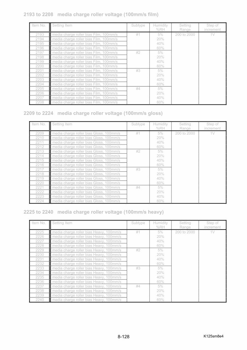
K125sm8e4 8-128
2193 to 2208 media charge roller voltage (100mm/s film)
2209 to 2224 media charge roller voltage (100mm/s gloss)
2225 to 2240 media charge roller voltage (100mm/s heavy)
Item No. Setting Item Subtype Humidity%RH
Setting Range
Step of increment
2193 media charge roller bias Film, 100mm/s #1 5% 200 to 2000 1V 2194 media charge roller bias Film, 100mm/s 20% 2195 media charge roller bias Film, 100mm/s 40% 2196 media charge roller bias Film, 100mm/s 60% 2197 media charge roller bias Film, 100mm/s #2 5% 2198 media charge roller bias Film, 100mm/s 20% 2199 media charge roller bias Film, 100mm/s 40% 2200 media charge roller bias Film, 100mm/s 60% 2201 media charge roller bias Film, 100mm/s #3 5% 2202 media charge roller bias Film, 100mm/s 20% 2203 media charge roller bias Film, 100mm/s 40% 2204 media charge roller bias Film, 100mm/s 60% 2205 media charge roller bias Film, 100mm/s #4 5% 2206 media charge roller bias Film, 100mm/s 20% 2207 media charge roller bias Film, 100mm/s 40% 2208 media charge roller bias Film, 100mm/s 60%
Item No. Setting Item Subtype Humidity%RH
Setting Range
Step of increment
2209 media charge roller bias Gloss, 100mm/s #1 5% 200 to 2000 1V 2210 media charge roller bias Gloss, 100mm/s 20% 2211 media charge roller bias Gloss, 100mm/s 40% 2212 media charge roller bias Gloss, 100mm/s 60% 2213 media charge roller bias Gloss, 100mm/s #2 5% 2214 media charge roller bias Gloss, 100mm/s 20% 2215 media charge roller bias Gloss, 100mm/s 40% 2216 media charge roller bias Gloss, 100mm/s 60% 2217 media charge roller bias Gloss, 100mm/s #3 5% 2218 media charge roller bias Gloss, 100mm/s 20% 2219 media charge roller bias Gloss, 100mm/s 40% 2220 media charge roller bias Gloss, 100mm/s 60% 2221 media charge roller bias Gloss, 100mm/s #4 5% 2222 media charge roller bias Gloss, 100mm/s 20% 2223 media charge roller bias Gloss, 100mm/s 40% 2224 media charge roller bias Gloss, 100mm/s 60%
Item No. Setting Item Subtype Humidity%RH
Setting Range
Step of increment
2225 media charge roller bias Heavy, 100mm/s #1 5% 200 to 2000 1V 2226 media charge roller bias Heavy, 100mm/s 20% 2227 media charge roller bias Heavy, 100mm/s 40% 2228 media charge roller bias Heavy, 100mm/s 60% 2229 media charge roller bias Heavy, 100mm/s #2 5% 2230 media charge roller bias Heavy, 100mm/s 20% 2231 media charge roller bias Heavy, 100mm/s 40% 2232 media charge roller bias Heavy, 100mm/s 60% 2233 media charge roller bias Heavy, 100mm/s #3 5% 2234 media charge roller bias Heavy, 100mm/s 20% 2235 media charge roller bias Heavy, 100mm/s 40% 2236 media charge roller bias Heavy, 100mm/s 60% 2237 media charge roller bias Heavy, 100mm/s #4 5% 2238 media charge roller bias Heavy, 100mm/s 20% 2239 media charge roller bias Heavy, 100mm/s 40% 2240 media charge roller bias Heavy, 100mm/s 60%
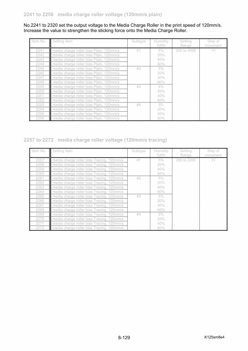
K125sm8e4 8-129
2241 to 2256 media charge roller voltage (120mm/s plain) No.2241 to 2320 set the output voltage to the Media Charge Roller in the print speed of 120mm/s. Increase the value to strengthen the sticking force onto the Media Charge Roller.
2257 to 2272 media charge roller voltage (120mm/s tracing)
Item No. Setting Item Subtype Humidity%RH
Setting Range
Step of increment
2241 media charge roller bias Plain, 120mm/s #1 5% 200 to 2000 1V 2242 media charge roller bias Plain, 120mm/s 20% 2243 media charge roller bias Plain, 120mm/s 40% 2244 media charge roller bias Plain, 120mm/s 60% 2245 media charge roller bias Plain, 120mm/s #2 5% 2246 media charge roller bias Plain, 120mm/s 20% 2247 media charge roller bias Plain, 120mm/s 40% 2248 media charge roller bias Plain, 120mm/s 60% 2249 media charge roller bias Plain, 120mm/s #3 5% 2250 media charge roller bias Plain, 120mm/s 20% 2251 media charge roller bias Plain, 120mm/s 40% 2252 media charge roller bias Plain, 120mm/s 60% 2253 media charge roller bias Plain, 120mm/s #4 5% 2254 media charge roller bias Plain, 120mm/s 20% 2255 media charge roller bias Plain, 120mm/s 40% 2256 media charge roller bias Plain, 120mm/s 60%
Item No. Setting Item Subtype Humidity%RH
Setting Range
Step of increment
2257 media charge roller bias Tracing, 120mm/s #1 5% 200 to 2000 1V 2258 media charge roller bias Tracing, 120mm/s 20% 2259 media charge roller bias Tracing, 120mm/s 40% 2260 media charge roller bias Tracing, 120mm/s 60% 2261 media charge roller bias Tracing, 120mm/s #2 5% 2262 media charge roller bias Tracing, 120mm/s 20% 2263 media charge roller bias Tracing, 120mm/s 40% 2264 media charge roller bias Tracing, 120mm/s 60% 2265 media charge roller bias Tracing, 120mm/s #3 5% 2266 media charge roller bias Tracing, 120mm/s 20% 2267 media charge roller bias Tracing, 120mm/s 40% 2268 media charge roller bias Tracing, 120mm/s 60% 2269 media charge roller bias Tracing, 120mm/s #4 5% 2270 media charge roller bias Tracing, 120mm/s 20% 2271 media charge roller bias Tracing, 120mm/s 40% 2272 media charge roller bias Tracing, 120mm/s 60%
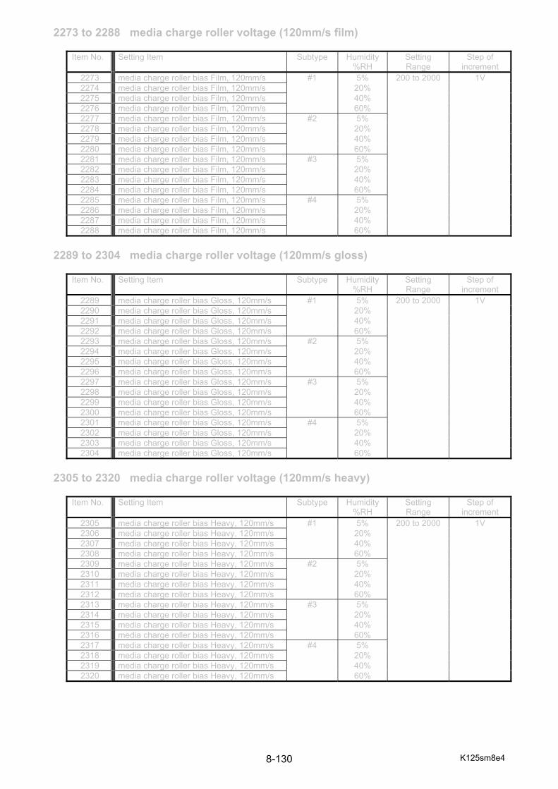
K125sm8e4 8-130
2273 to 2288 media charge roller voltage (120mm/s film)
2289 to 2304 media charge roller voltage (120mm/s gloss)
2305 to 2320 media charge roller voltage (120mm/s heavy)
Item No. Setting Item Subtype Humidity%RH
Setting Range
Step of increment
2273 media charge roller bias Film, 120mm/s #1 5% 200 to 2000 1V 2274 media charge roller bias Film, 120mm/s 20% 2275 media charge roller bias Film, 120mm/s 40% 2276 media charge roller bias Film, 120mm/s 60% 2277 media charge roller bias Film, 120mm/s #2 5% 2278 media charge roller bias Film, 120mm/s 20% 2279 media charge roller bias Film, 120mm/s 40% 2280 media charge roller bias Film, 120mm/s 60% 2281 media charge roller bias Film, 120mm/s #3 5% 2282 media charge roller bias Film, 120mm/s 20% 2283 media charge roller bias Film, 120mm/s 40% 2284 media charge roller bias Film, 120mm/s 60% 2285 media charge roller bias Film, 120mm/s #4 5% 2286 media charge roller bias Film, 120mm/s 20% 2287 media charge roller bias Film, 120mm/s 40% 2288 media charge roller bias Film, 120mm/s 60%
Item No. Setting Item Subtype Humidity%RH
Setting Range
Step of increment
2289 media charge roller bias Gloss, 120mm/s #1 5% 200 to 2000 1V 2290 media charge roller bias Gloss, 120mm/s 20% 2291 media charge roller bias Gloss, 120mm/s 40% 2292 media charge roller bias Gloss, 120mm/s 60% 2293 media charge roller bias Gloss, 120mm/s #2 5% 2294 media charge roller bias Gloss, 120mm/s 20% 2295 media charge roller bias Gloss, 120mm/s 40% 2296 media charge roller bias Gloss, 120mm/s 60% 2297 media charge roller bias Gloss, 120mm/s #3 5% 2298 media charge roller bias Gloss, 120mm/s 20% 2299 media charge roller bias Gloss, 120mm/s 40% 2300 media charge roller bias Gloss, 120mm/s 60% 2301 media charge roller bias Gloss, 120mm/s #4 5% 2302 media charge roller bias Gloss, 120mm/s 20% 2303 media charge roller bias Gloss, 120mm/s 40% 2304 media charge roller bias Gloss, 120mm/s 60%
Item No. Setting Item Subtype Humidity%RH
Setting Range
Step of increment
2305 media charge roller bias Heavy, 120mm/s #1 5% 200 to 2000 1V 2306 media charge roller bias Heavy, 120mm/s 20% 2307 media charge roller bias Heavy, 120mm/s 40% 2308 media charge roller bias Heavy, 120mm/s 60% 2309 media charge roller bias Heavy, 120mm/s #2 5% 2310 media charge roller bias Heavy, 120mm/s 20% 2311 media charge roller bias Heavy, 120mm/s 40% 2312 media charge roller bias Heavy, 120mm/s 60% 2313 media charge roller bias Heavy, 120mm/s #3 5% 2314 media charge roller bias Heavy, 120mm/s 20% 2315 media charge roller bias Heavy, 120mm/s 40% 2316 media charge roller bias Heavy, 120mm/s 60% 2317 media charge roller bias Heavy, 120mm/s #4 5% 2318 media charge roller bias Heavy, 120mm/s 20% 2319 media charge roller bias Heavy, 120mm/s 40% 2320 media charge roller bias Heavy, 120mm/s 60%
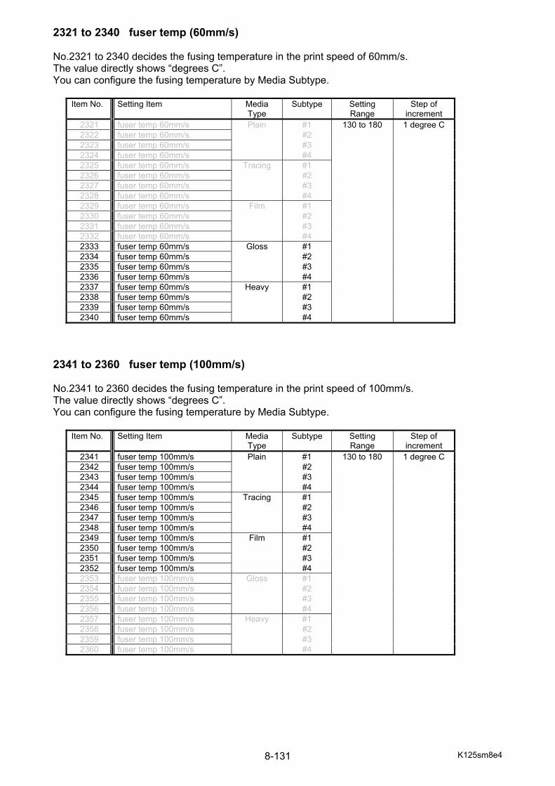
K125sm8e4 8-131
2321 to 2340 fuser temp (60mm/s) No.2321 to 2340 decides the fusing temperature in the print speed of 60mm/s. The value directly shows “degrees C”. You can configure the fusing temperature by Media Subtype.
2341 to 2360 fuser temp (100mm/s) No.2341 to 2360 decides the fusing temperature in the print speed of 100mm/s. The value directly shows “degrees C”. You can configure the fusing temperature by Media Subtype.
Item No. Setting Item Media Type
Subtype Setting Range
Step of increment
2321 fuser temp 60mm/s Plain #1 130 to 180 1 degree C 2322 fuser temp 60mm/s #2 2323 fuser temp 60mm/s #3 2324 fuser temp 60mm/s #4 2325 fuser temp 60mm/s Tracing #1 2326 fuser temp 60mm/s #2 2327 fuser temp 60mm/s #3 2328 fuser temp 60mm/s #4 2329 fuser temp 60mm/s Film #1 2330 fuser temp 60mm/s #2 2331 fuser temp 60mm/s #3 2332 fuser temp 60mm/s #4 2333 fuser temp 60mm/s Gloss #1 2334 fuser temp 60mm/s #2 2335 fuser temp 60mm/s #3 2336 fuser temp 60mm/s #4 2337 fuser temp 60mm/s Heavy #1 2338 fuser temp 60mm/s #2 2339 fuser temp 60mm/s #3 2340 fuser temp 60mm/s #4
Item No. Setting Item Media Type
Subtype Setting Range
Step of increment
2341 fuser temp 100mm/s Plain #1 130 to 180 1 degree C 2342 fuser temp 100mm/s #2 2343 fuser temp 100mm/s #3 2344 fuser temp 100mm/s #4 2345 fuser temp 100mm/s Tracing #1 2346 fuser temp 100mm/s #2 2347 fuser temp 100mm/s #3 2348 fuser temp 100mm/s #4 2349 fuser temp 100mm/s Film #1 2350 fuser temp 100mm/s #2 2351 fuser temp 100mm/s #3 2352 fuser temp 100mm/s #4 2353 fuser temp 100mm/s Gloss #1 2354 fuser temp 100mm/s #2 2355 fuser temp 100mm/s #3 2356 fuser temp 100mm/s #4 2357 fuser temp 100mm/s Heavy #1 2358 fuser temp 100mm/s #2 2359 fuser temp 100mm/s #3 2360 fuser temp 100mm/s #4
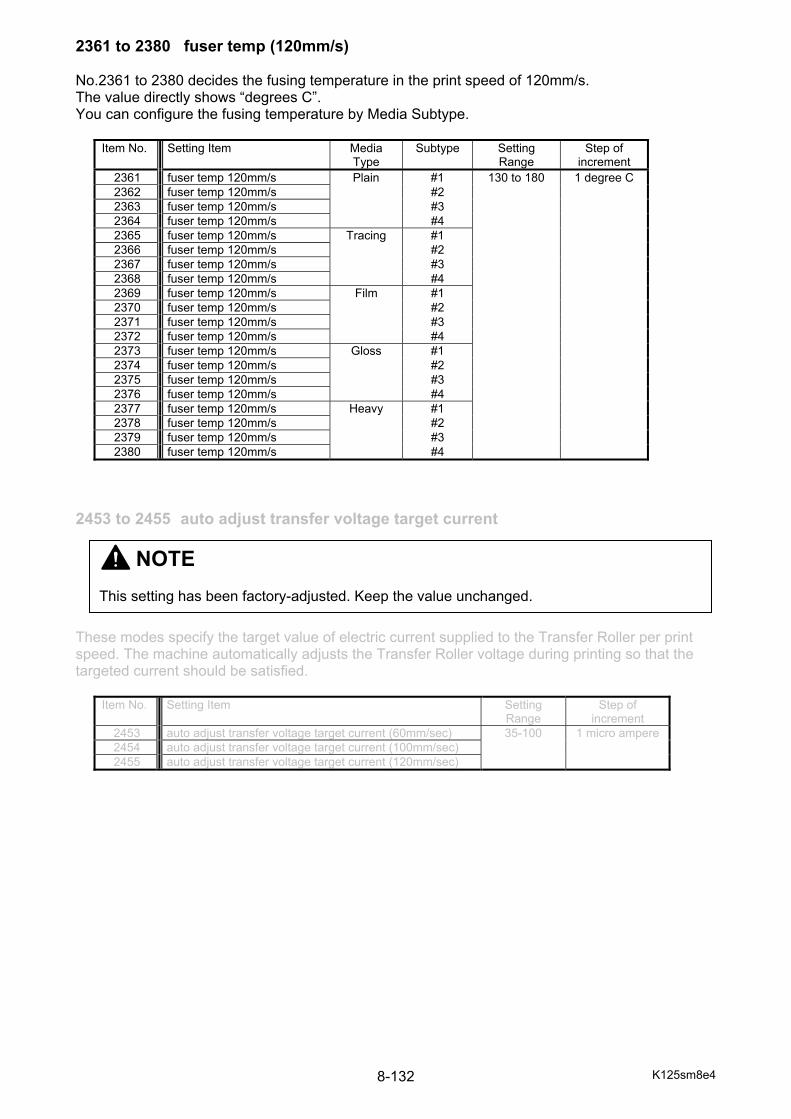
K125sm8e4 8-132
2361 to 2380 fuser temp (120mm/s) No.2361 to 2380 decides the fusing temperature in the print speed of 120mm/s. The value directly shows “degrees C”. You can configure the fusing temperature by Media Subtype.
2453 to 2455 auto adjust transfer voltage target current These modes specify the target value of electric current supplied to the Transfer Roller per print speed. The machine automatically adjusts the Transfer Roller voltage during printing so that the targeted current should be satisfied.
Item No. Setting Item Setting Range
Step of increment
2453 auto adjust transfer voltage target current (60mm/sec) 35-100 1 micro ampere2454 auto adjust transfer voltage target current (100mm/sec) 2455 auto adjust transfer voltage target current (120mm/sec)
Item No. Setting Item Media Type
Subtype Setting Range
Step of increment
2361 fuser temp 120mm/s Plain #1 130 to 180 1 degree C 2362 fuser temp 120mm/s #2 2363 fuser temp 120mm/s #3 2364 fuser temp 120mm/s #4 2365 fuser temp 120mm/s Tracing #1 2366 fuser temp 120mm/s #2 2367 fuser temp 120mm/s #3 2368 fuser temp 120mm/s #4 2369 fuser temp 120mm/s Film #1 2370 fuser temp 120mm/s #2 2371 fuser temp 120mm/s #3 2372 fuser temp 120mm/s #4 2373 fuser temp 120mm/s Gloss #1 2374 fuser temp 120mm/s #2 2375 fuser temp 120mm/s #3 2376 fuser temp 120mm/s #4 2377 fuser temp 120mm/s Heavy #1 2378 fuser temp 120mm/s #2 2379 fuser temp 120mm/s #3 2380 fuser temp 120mm/s #4
NOTE This setting has been factory-adjusted. Keep the value unchanged.
K125sm8e4 8-133
2468 to 2503 transfer roller voltage offset These items specify the voltages that are applied to the Transfer Roller. The voltage specified here is applied to the Transfer Roller only when a printing media is running between Drum and concerning Transfer Roller. Setting value stands for "additional XV" against the optimum voltage calculated automatically by the Auto Transfer Roller Voltage Adjustment function. (When there no media is running between drum and concerning Transfer Roller, the optimum voltage calculated by the Auto Transfer Roller Voltage Adjustment function is simply applied as it is.) Setting the value of Transfer Roller Voltage Offset to higher value is effective for keeping the white (blank) image area of CAD print in a good quality condition. On the contrary, decrement of the value for a poster/graphic image tends to be more effective for better image color.
Item No. Setting Item Setting Range
Step of increment
2468 transfer roller voltage offset (process #1 60mm/s large) 0-500 1 V 2469 transfer roller voltage offset (process #1 60mm/s middle) 2470 transfer roller voltage offset (process #1 60mm/s short) 2471 transfer roller voltage offset (process #1 100mm/s large) 2472 transfer roller voltage offset (process #1 100mm/s middle) 2473 transfer roller voltage offset (process #1 100mm/s short) 2474 transfer roller voltage offset (process #1 120mm/s large) 2475 transfer roller voltage offset (process #1 120mm/s middle) 2476 transfer roller voltage offset (process #1 120mm/s short) 2477 transfer roller voltage offset (process #1 60mm/s large) 2478 transfer roller voltage offset (process #2 60mm/s middle) 2479 transfer roller voltage offset (process #2 60mm/s short) 2480 transfer roller voltage offset (process #2 100mm/s large) 2481 transfer roller voltage offset (process #2 100mm/s middle) 2482 transfer roller voltage offset (process #2 100mm/s short) 2483 transfer roller voltage offset (process #2 120mm/s large) 2484 transfer roller voltage offset (process #2 120mm/s middle) 2485 transfer roller voltage offset (process #2 120mm/s short) 2486 transfer roller voltage offset (process #3 60mm/s large) 2487 transfer roller voltage offset (process #3 60mm/s middle) 2488 transfer roller voltage offset (process #3 60mm/s short) 2489 transfer roller voltage offset (process #3 100mm/s large) 2490 transfer roller voltage offset (process #3 100mm/s middle) 2491 transfer roller voltage offset (process #3 100mm/s short) 2492 transfer roller voltage offset (process #3 120mm/s large) 2493 transfer roller voltage offset (process #3 120mm/s middle) 2494 transfer roller voltage offset (process #3 120mm/s short) 2495 transfer roller voltage offset (process #4 60mm/s large) 2496 transfer roller voltage offset (process #4 60mm/s middle) 2497 transfer roller voltage offset (process #4 60mm/s short) 2498 transfer roller voltage offset (process #4 100mm/s large) 2499 transfer roller voltage offset (process #4 100mm/s middle) 2500 transfer roller voltage offset (process #4 100mm/s short) 2501 transfer roller voltage offset (process #4 120mm/s large) 2502 transfer roller voltage offset (process #4 120mm/s middle) 2503 transfer roller voltage offset (process #4 120mm/s short)
When no media is running between the Drum and the concerning Transfer Roller, the optimum voltage calculated by the Auto Transfer Roller Voltage Adjustment function is simply applied without being compensated by the offset voltage specified here. When media arrives the concerning Transfer Roller, the voltage applied to the Transfer Roller is the sum of "optimum voltage" and "offset voltage".
Reference
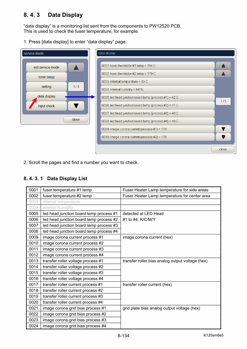
K125sm8e5 8-134
8. 4. 3 Data Display “data display” is a monitoring list sent from the components to PW12520 PCB. This is used to check the fuser temperature, for example. 1. Press [data display] to enter “data display” page. 2. Scroll the pages and find a number you want to check. 8. 4. 3. 1 Data Display List
0001 fuser temperature #1 temp Fuser Heater Lamp temperature for side areas 0002 fuser temperature #2 temp Fuser Heater Lamp temperature for center area 0003 internal temperature 0004 internal humidity 0005 led head junction board temp process #1 detected at LED Head 0006 led head junction board temp process #2 #1 to #4: K/C/M/Y 0007 led head junction board temp process #3 0008 led head junction board temp process #4 0009 image corona current process #1 image corona current (hex) 0010 image corona current process #2 0011 image corona current process #3 0012 image corona current process #4 0013 transfer roller voltage process #1 transfer roller bias analog output voltage (hex) 0014 transfer roller voltage process #2 0015 transfer roller voltage process #3 0016 transfer roller voltage process #4 0017 transfer roller current process #1 transfer roller current (hex) 0018 transfer roller current process #2 0019 transfer roller current process #3 0020 transfer roller current process #4 0021 image corona grid bias process #1 grid plate bias analog output voltage (hex) 0022 image corona grid bias process #2 0023 image corona grid bias process #3 0024 image corona grid bias process #4
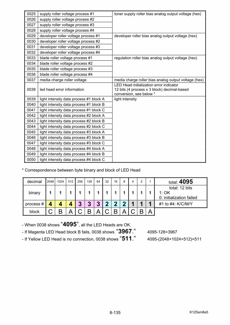
K125sm8e5 8-135
0025 supply roller voltage process #1 toner supply roller bias analog output voltage (hex) 0026 supply roller voltage process #2 0027 supply roller voltage process #3 0028 supply roller voltage process #4 0029 developer roller voltage process #1 developer roller bias analog output voltage (hex) 0030 developer roller voltage process #2 0031 developer roller voltage process #3 0032 developer roller voltage process #4 0033 blade roller voltage process #1 regulation roller bias analog output voltage (hex) 0034 blade roller voltage process #2 0035 blade roller voltage process #3 0036 blade roller voltage process #4 0037 media charge roller voltage media charge roller bias analog output voltage (hex)
0038 led head error information LED Head initialization error indicator 12 bits (4 process x 3 block) decimal-based conversion, see below *
0039 light intensity data process #1 block A light intensity 0040 light intensity data process #1 block B 0041 light intensity data process #1 block C 0042 light intensity data process #2 block A 0043 light intensity data process #2 block B 0044 light intensity data process #2 block C 0045 light intensity data process #3 block A 0046 light intensity data process #3 block B 0047 light intensity data process #3 block C 0048 light intensity data process #4 block A 0049 light intensity data process #4 block B 0050 light intensity data process #4 block C
* Correspondence between byte binary and block of LED Head
decimal 2048 1024 512 256 128 64 32 16 8 4 2 1 total: 4095 binary 1 1 1 1 1 1 1 1 1 1 1 1
total: 12 bits 1: OK 0: initialization failed
process # 4 4 4 3 3 3 2 2 2 1 1 1 #1 to #4: K/C/M/Y
block C B A C B A C B A C B A - When 0038 shows “4095”, all the LED Heads are OK.
- If Magenta LED Head block B fails, 0038 shows “3967.” 4095-128=3967
- If Yellow LED Head is no connection, 0038 shows “511.” 4095-(2048+1024+512)=511

K125sm8e5 8-136
8. 4. 4 Input Check “input check” is to monitor the current input signal status sent from electric components. Press [input check] to enter “input check” page. Input Check has 9 groups and you can change the page with [next] [prev] buttons on the bottom left of “input check” page.
(1/9) process 1 Process Unit (K) HV, Developer Unit (K), Bypass Feeder Sensors
(2/9) process 2 Process Unit (C) HV, Developer Unit (C) (3/9) process 3 Process Unit (M) HV, Developer Unit (M)
(4/9) process 4 Process Unit (Y) HV, Developer Unit (Y), Lower Feeder, Waste Toner Box (Drum)
(5/9) belt / fuser Belt Unit, Fuser Unit, Rear Door, Left Door (6/9) paper feed Media charge Roller (7/9) deck 1 Roll Deck 1 Sensors, Cutter Unit 1 (8/9) deck 2 Roll Deck 2 Sensors, Cutter Unit 2 (9/9) deck 3 Roll Deck 3 Sensors, Cutter Unit 3
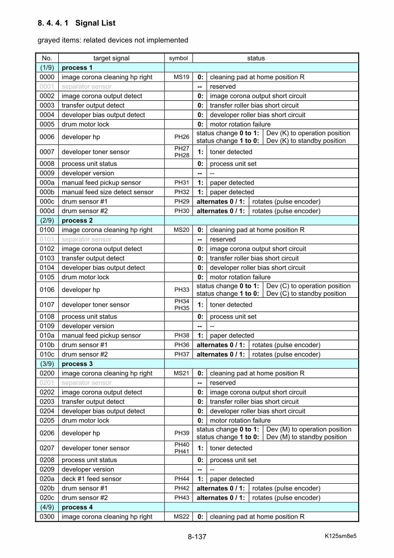
K125sm8e5 8-137
8. 4. 4. 1 Signal List grayed items: related devices not implemented
No. target signal symbol status (1/9) process 1 0000 image corona cleaning hp right MS19 0: cleaning pad at home position R 0001 separator sensor -- reserved 0002 image corona output detect 0: image corona output short circuit 0003 transfer output detect 0: transfer roller bias short circuit 0004 developer bias output detect 0: developer roller bias short circuit 0005 drum motor lock 0: motor rotation failure
0006 developer hp PH26 status change 0 to 1:status change 1 to 0:
Dev (K) to operation position Dev (K) to standby position
0007 developer toner sensor PH27PH28 1: toner detected
0008 process unit status 0: process unit set 0009 developer version -- -- 000a manual feed pickup sensor PH31 1: paper detected 000b manual feed size detect sensor PH32 1: paper detected 000c drum sensor #1 PH29 alternates 0 / 1: rotates (pulse encoder) 000d drum sensor #2 PH30 alternates 0 / 1: rotates (pulse encoder) (2/9) process 2 0100 image corona cleaning hp right MS20 0: cleaning pad at home position R 0101 separator sensor -- reserved 0102 image corona output detect 0: image corona output short circuit 0103 transfer output detect 0: transfer roller bias short circuit 0104 developer bias output detect 0: developer roller bias short circuit 0105 drum motor lock 0: motor rotation failure
0106 developer hp PH33 status change 0 to 1:status change 1 to 0:
Dev (C) to operation position Dev (C) to standby position
0107 developer toner sensor PH34PH35 1: toner detected
0108 process unit status 0: process unit set 0109 developer version -- -- 010a manual feed pickup sensor PH38 1: paper detected 010b drum sensor #1 PH36 alternates 0 / 1: rotates (pulse encoder) 010c drum sensor #2 PH37 alternates 0 / 1: rotates (pulse encoder) (3/9) process 3 0200 image corona cleaning hp right MS21 0: cleaning pad at home position R 0201 separator sensor -- reserved 0202 image corona output detect 0: image corona output short circuit 0203 transfer output detect 0: transfer roller bias short circuit 0204 developer bias output detect 0: developer roller bias short circuit 0205 drum motor lock 0: motor rotation failure
0206 developer hp PH39 status change 0 to 1:status change 1 to 0:
Dev (M) to operation position Dev (M) to standby position
0207 developer toner sensor PH40PH41 1: toner detected
0208 process unit status 0: process unit set 0209 developer version -- -- 020a deck #1 feed sensor PH44 1: paper detected 020b drum sensor #1 PH42 alternates 0 / 1: rotates (pulse encoder) 020c drum sensor #2 PH43 alternates 0 / 1: rotates (pulse encoder) (4/9) process 4 0300 image corona cleaning hp right MS22 0: cleaning pad at home position R
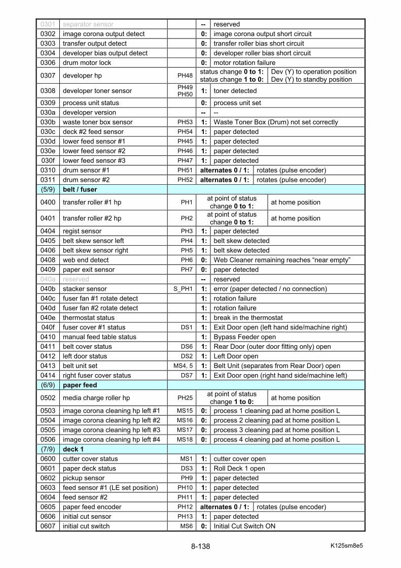
K125sm8e5 8-138
0301 separator sensor -- reserved 0302 image corona output detect 0: image corona output short circuit 0303 transfer output detect 0: transfer roller bias short circuit 0304 developer bias output detect 0: developer roller bias short circuit 0306 drum motor lock 0: motor rotation failure
0307 developer hp PH48 status change 0 to 1:status change 1 to 0:
Dev (Y) to operation position Dev (Y) to standby position
0308 developer toner sensor PH49PH50 1: toner detected
0309 process unit status 0: process unit set 030a developer version -- -- 030b waste toner box sensor PH53 1: Waste Toner Box (Drum) not set correctly 030c deck #2 feed sensor PH54 1: paper detected 030d lower feed sensor #1 PH45 1: paper detected 030e lower feed sensor #2 PH46 1: paper detected 030f lower feed sensor #3 PH47 1: paper detected 0310 drum sensor #1 PH51 alternates 0 / 1: rotates (pulse encoder) 0311 drum sensor #2 PH52 alternates 0 / 1: rotates (pulse encoder) (5/9) belt / fuser
0400 transfer roller #1 hp PH1 at point of status change 0 to 1: at home position
0401 transfer roller #2 hp PH2 at point of status change 0 to 1: at home position
0404 regist sensor PH3 1: paper detected 0405 belt skew sensor left PH4 1: belt skew detected 0406 belt skew sensor right PH5 1: belt skew detected 0408 web end detect PH6 0: Web Cleaner remaining reaches “near empty” 0409 paper exit sensor PH7 0: paper detected 040a reserved -- reserved 040b stacker sensor S_PH1 1: error (paper detected / no connection) 040c fuser fan #1 rotate detect 1: rotation failure 040d fuser fan #2 rotate detect 1: rotation failure 040e thermostat status 1: break in the thermostat 040f fuser cover #1 status DS1 1: Exit Door open (left hand side/machine right) 0410 manual feed table status 1: Bypass Feeder open 0411 belt cover status DS6 1: Rear Door (outer door fitting only) open 0412 left door status DS2 1: Left Door open 0413 belt unit set MS4, 5 1: Belt Unit (separates from Rear Door) open 0414 right fuser cover status DS7 1: Exit Door open (right hand side/machine left) (6/9) paper feed
0502 media charge roller hp PH25 at point of status change 1 to 0: at home position
0503 image corona cleaning hp left #1 MS15 0: process 1 cleaning pad at home position L 0504 image corona cleaning hp left #2 MS16 0: process 2 cleaning pad at home position L 0505 image corona cleaning hp left #3 MS17 0: process 3 cleaning pad at home position L 0506 image corona cleaning hp left #4 MS18 0: process 4 cleaning pad at home position L (7/9) deck 1 0600 cutter cover status MS1 1: cutter cover open 0601 paper deck status DS3 1: Roll Deck 1 open 0602 pickup sensor PH9 1: paper detected 0603 feed sensor #1 (LE set position) PH10 1: paper detected 0604 feed sensor #2 PH11 1: paper detected 0605 paper feed encoder PH12 alternates 0 / 1: rotates (pulse encoder) 0606 initial cut sensor PH13 1: paper detected 0607 initial cut switch MS6 0: Initial Cut Switch ON
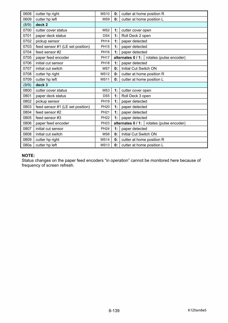
K125sm8e5 8-139
0608 cutter hp right MS10 0: cutter at home position R 0609 cutter hp left MS9 0: cutter at home position L (8/9) deck 2 0700 cutter cover status MS2 1: cutter cover open 0701 paper deck status DS4 1: Roll Deck 2 open 0702 pickup sensor PH14 1: paper detected 0703 feed sensor #1 (LE set position) PH15 1: paper detected 0704 feed sensor #2 PH16 1: paper detected 0705 paper feed encoder PH17 alternates 0 / 1: rotates (pulse encoder) 0706 initial cut sensor PH18 1: paper detected 0707 initial cut switch MS7 0: Initial Cut Switch ON 0708 cutter hp right MS12 0: cutter at home position R 0709 cutter hp left MS11 0: cutter at home position L (9/9) deck 3 0800 cutter cover status MS3 1: cutter cover open 0801 paper deck status DS5 1: Roll Deck 3 open 0802 pickup sensor PH19 1: paper detected 0803 feed sensor #1 (LE set position) PH20 1: paper detected 0804 feed sensor #2 PH21 1: paper detected 0805 feed sensor #3 PH22 1: paper detected 0806 paper feed encoder PH23 alternates 0 / 1: rotates (pulse encoder) 0807 initial cut sensor PH24 1: paper detected 0808 initial cut switch MS8 0: Initial Cut Switch ON 0809 cutter hp right MS14 0: cutter at home position R 080a cutter hp left MS13 0: cutter at home position L
NOTE: Status changes on the paper feed encoders “in operation” cannot be monitored here because of frequency of screen refresh.
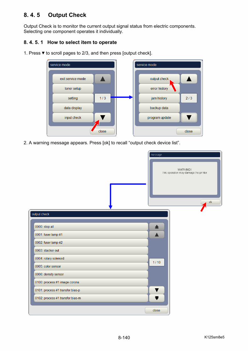
K125sm8e5 8-140
8. 4. 5 Output Check Output Check is to monitor the current output signal status from electric components. Selecting one component operates it individually. 8. 4. 5. 1 How to select item to operate 1. Press to scroll pages to 2/3, and then press [output check]. 2. A warning message appears. Press [ok] to recall “output check device list”.
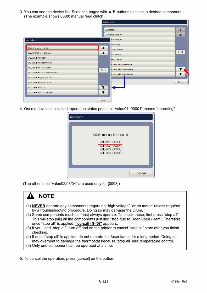
K125sm8e5 8-141
3. You can see the device list. Scroll the pages with ▲▼ buttons to select a desired component. (The example shows 0608: manual feed clutch) 4. Once a device is selected, operation status pops up. “value01: 00001” means “operating”. (The other lines “value02/03/04” are used only for [0008]) 5. To cancel the operation, press [cancel] on the bottom.
NOTE (1) NEVER operate any components regarding “high voltage” “drum motor” unless required
by a troubleshooting procedure. Doing so may damage the Drum. (2) Some components (such as fans) always operate. To check these, first press “stop all”.
This will stop (kill) all the components just like “stop due to Door Open / Jam”. Therefore, once “stop all” is applied, “ce-call (ff-f0)” appears.
(3) If you used “stop all”, turn off and on the printer to cancel “stop all” state after you finish checking.
(4) If once “stop all” is applied, do not operate the fuser lamps for a long period. Doing so may overheat to damage the thermostat because “stop all” kills temperature control.
(5) Only one component can be operated at a time.
K125sm8e5 8-142
8. 4. 5. 2 Component List Never operate grayed components.
No. target No. target
0000 stop all 0404 process #4 developer bias-p 0001 fuser lamp #1 H1 0405 process #4 developer bias-m 0002 fuser lamp #2 H2 0406 process #4 drum motor M150003 (reserved) 0407 process #4 toner bottle motor M250004 flapper control solenoid SL2 0408 process #4 eraser lamp 0005 color sensor 0409 process #4 image corona cleaning (R L) M300006 density sensor 040a process #4 image corona cleaning reverse M300007 sleep mode 040b process #4 developer set motor M210008 color sensor position 040c process #4 cooling fan FM40100 process #1 image corona 040d media charge bias 0101 process #1 transfer bias-p 0500 belt motor M60102 process #1 transfer bias-m 0501 fuser motor M110104 process #1 developer bias-p 0502 transfer roller #1 set motor M160105 process #1 developer bias-m 0503 transfer roller #2 set motor M170106 process #1 drum motor M12 0506 web motor M100107 process #1 toner bottle motor M22 0507 fuser cooling fan #1 BL10108 process #1 eraser lamp 0508 fuser cooling fan #2 BL20109 process #1 image corona cleaning (R L) M27 0509 pressure fan #1 #2 FM5, FM6010a process #1 image corona cleaning reverse M27 050a stacker fan S_BL1, S_BL2010b process #1 developer set motor M18 050b pressure fan #3 FM7010c process #1 cooling fan FM1 050c separate guide solenoid SL3, SL4010d pressure fan #4 #5 FM12, FM13 050d stacker motor S_M1010e pressure fan #6 #7 FM14, FM15 0600 paper feed motor M50200 process #2 image corona 0601 paper feed motor reverse M50201 process #2 transfer bias-p 0602 manual feed motor M40202 process #2 transfer bias-m 0605 media charge roller set motor M260204 process #2 developer bias-p 0606 paper feed clutch #1 (Reserved) 0205 process #2 developer bias-m 0607 paper feed clutch CL90206 process #2 drum motor M13 0608 manual feed clutch CL80207 process #2 toner bottle motor M23 0609 manual feed solenoid SL10208 process #2 eraser lamp 0700 deck #1 motor M10209 process #2 image corona cleaning (R L) M28 0701 deck #1 motor reverse M1020a process #2 image corona cleaning reverse M28 0702 deck #1 cutter motor M7020b process #2 developer set motor M19 0703 deck #1 cutter motor reverse M7020c process #2 cooling fan FM2 0704 deck #1 pickup clutch CL10300 process #3 image corona 0705 deck #1 rewind clutch CL20301 process #3 transfer bias-p 0800 deck #2 motor M20302 process #3 transfer bias-m 0801 deck #2 motor reverse M20304 process #3 developer bias-p 0802 deck #2 cutter motor M80305 process #3 developer bias-m 0803 deck #2 cutter motor reverse M80306 process #3 drum motor M14 0804 deck #2 pickup clutch CL30307 process #3 toner bottle motor M24 0805 deck #2 rewind clutch CL40308 process #3 eraser lamp 0900 deck #3 motor M30309 process #3 image corona cleaning (R L) M29 0901 deck #3 motor reverse M3030a process #3 image corona cleaning reverse M29 0902 deck #3 cutter motor M9030b process #3 developer set motor M20 0903 deck #3 cutter motor reverse M9030c process #3 cooling fan FM3 0904 deck #3 pickup clutch CL50400 process #4 image corona 0905 deck #3 rewind clutch CL60401 process #4 transfer bias-p -- 0402 process #4 transfer bias-m --
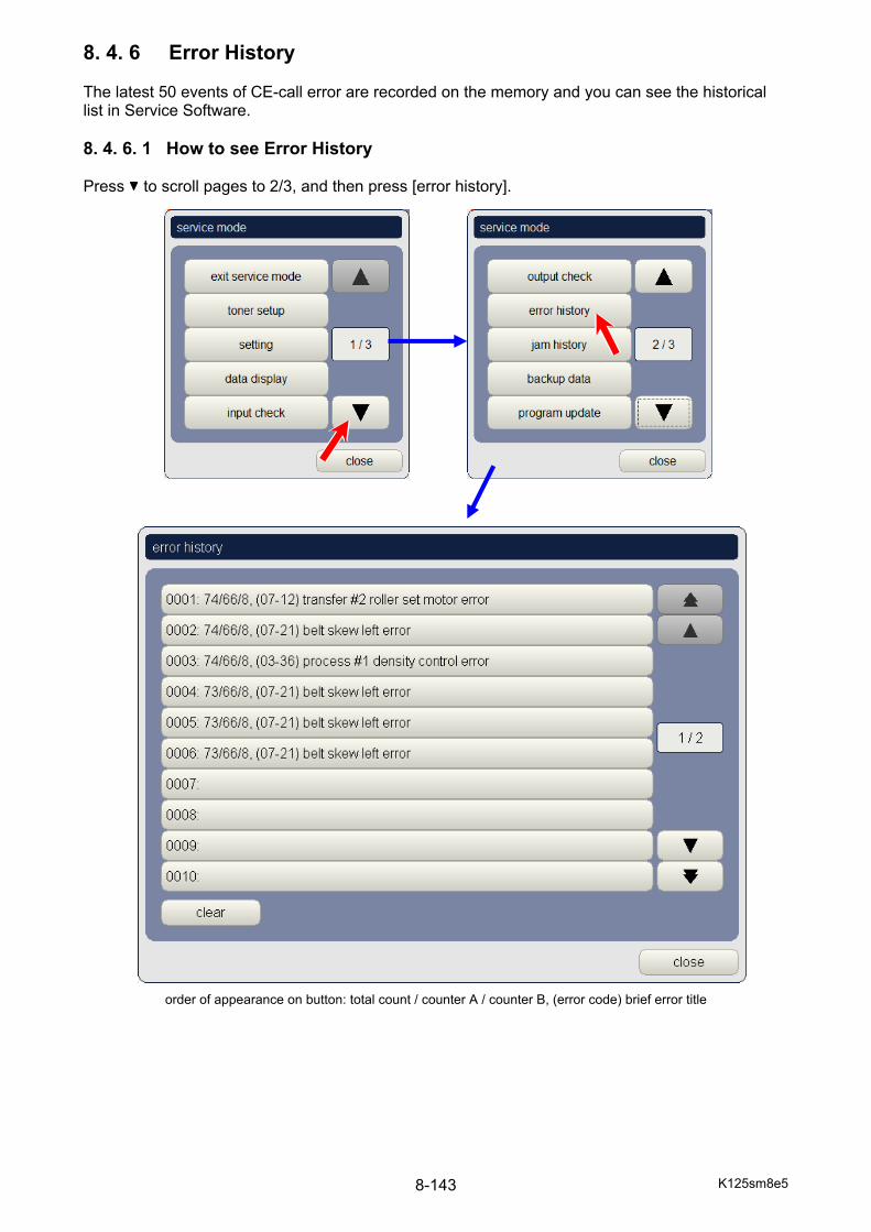
K125sm8e5 8-143
8. 4. 6 Error History The latest 50 events of CE-call error are recorded on the memory and you can see the historical list in Service Software. 8. 4. 6. 1 How to see Error History Press to scroll pages to 2/3, and then press [error history].
order of appearance on button: total count / counter A / counter B, (error code) brief error title
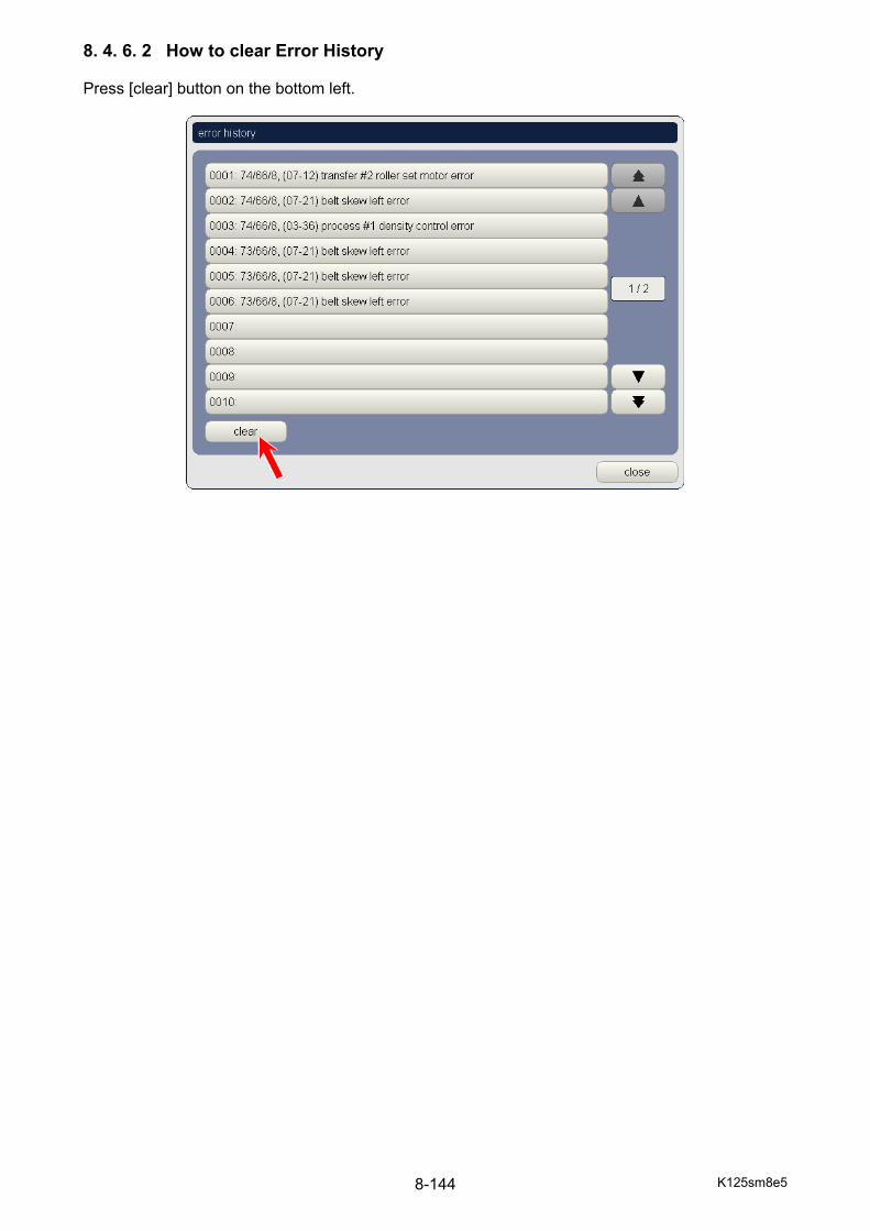
K125sm8e5 8-144
8. 4. 6. 2 How to clear Error History Press [clear] button on the bottom left.
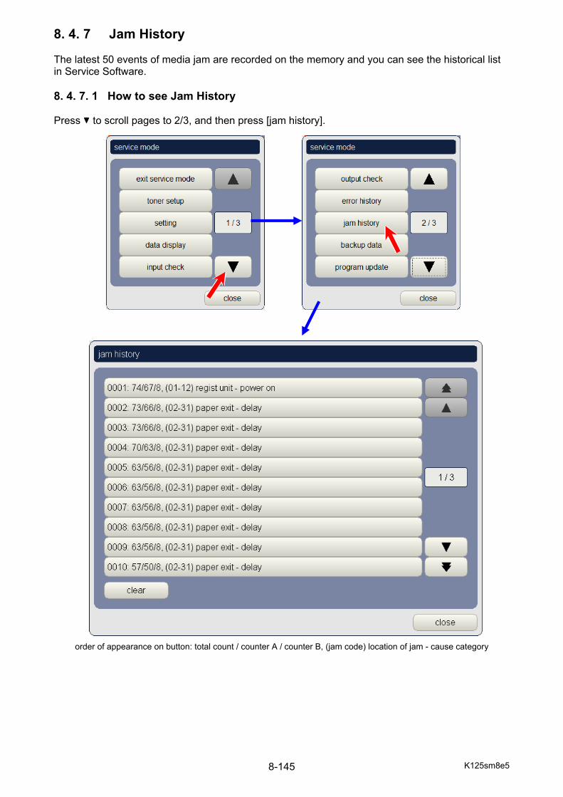
K125sm8e5 8-145
8. 4. 7 Jam History The latest 50 events of media jam are recorded on the memory and you can see the historical list in Service Software. 8. 4. 7. 1 How to see Jam History Press to scroll pages to 2/3, and then press [jam history].
order of appearance on button: total count / counter A / counter B, (jam code) location of jam - cause category
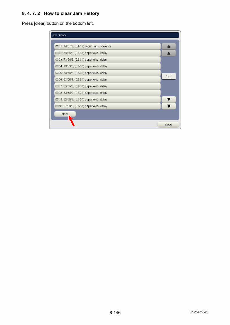
K125sm8e5 8-146
8. 4. 7. 2 How to clear Jam History Press [clear] button on the bottom left.
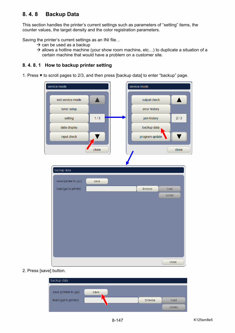
K125sm8e5 8-147
8. 4. 8 Backup Data This section handles the printer’s current settings such as parameters of “setting” items, the counter values, the target density and the color registration parameters. Saving the printer’s current settings as an INI file…
can be used as a backup allows a hotline machine (your show room machine, etc…) to duplicate a situation of a certain machine that would have a problem on a customer site.
8. 4. 8. 1 How to backup printer setting 1. Press to scroll pages to 2/3, and then press [backup data] to enter “backup” page. 2. Press [save] button.

K125sm8e5 8-148
3. Enter a file name and press [ok]. The file name “YYYYMMddmmss” is automatically given.
4. If the system is ready to use your USB storage device, you can choose the location of the
default storage directory on the controller or your removable storage. A location popup will appear. Select “E:\” to save the INI file to the removable storage. (Drive letter depends)
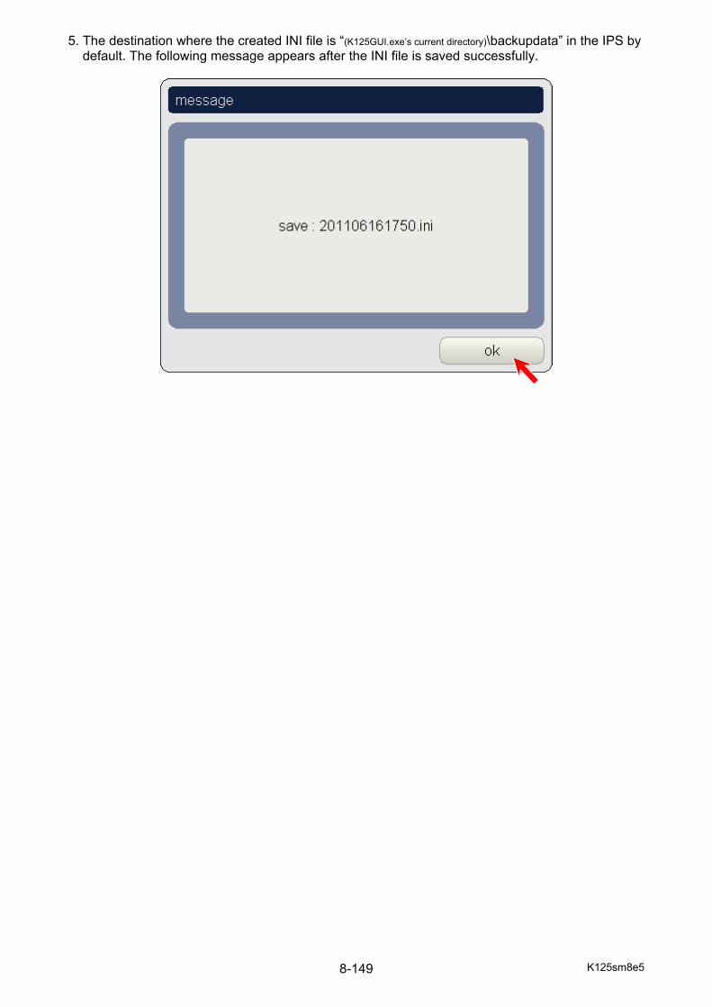
K125sm8e5 8-149
5. The destination where the created INI file is “(K125GUI.exe’s current directory)\backupdata” in the IPS by default. The following message appears after the INI file is saved successfully.

K125sm8e5 8-150
8. 4. 8. 2 How to restore printer setting 1. Press to scroll pages to 2/3, and then press [backup data] to enter “backup” page. 2. Press [browse] button.
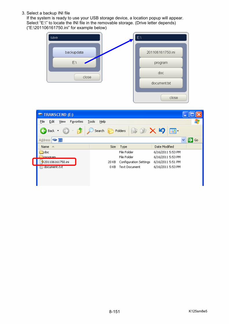
K125sm8e5 8-151
3. Select a backup INI file If the system is ready to use your USB storage device, a location popup will appear. Select “E:\” to locate the INI file in the removable storage. (Drive letter depends) (“E:\201106161750.ini” for example below)
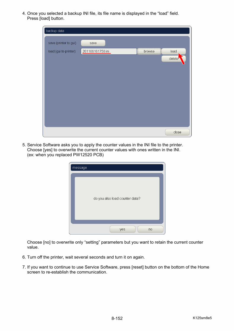
K125sm8e5 8-152
4. Once you selected a backup INI file, its file name is displayed in the “load” field. Press [load] button.
5. Service Software asks you to apply the counter values in the INI file to the printer.
Choose [yes] to overwrite the current counter values with ones written in the INI. (ex: when you replaced PW12520 PCB)
Choose [no] to overwrite only “setting” parameters but you want to retain the current counter value.
6. Turn off the printer, wait several seconds and turn it on again. 7. If you want to continue to use Service Software, press [reset] button on the bottom of the Home
screen to re-establish the communication.
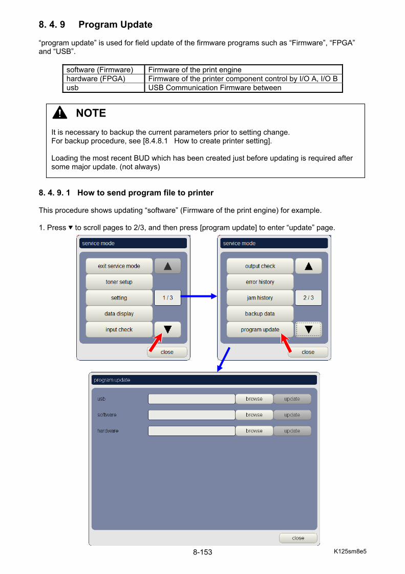
K125sm8e5 8-153
8. 4. 9 Program Update “program update” is used for field update of the firmware programs such as “Firmware”, “FPGA” and “USB”.
software (Firmware) Firmware of the print engine hardware (FPGA) Firmware of the printer component control by I/O A, I/O Busb USB Communication Firmware between
8. 4. 9. 1 How to send program file to printer This procedure shows updating “software” (Firmware of the print engine) for example. 1. Press to scroll pages to 2/3, and then press [program update] to enter “update” page.
NOTE It is necessary to backup the current parameters prior to setting change. For backup procedure, see [8.4.8.1 How to create printer setting]. Loading the most recent BUD which has been created just before updating is required after some major update. (not always)

K125sm8e5 8-154
2. Press [browse] button in a category of “usb” “software” “hardware” you will update.
3. Locate a firmware. The default destination is as follows. A USB storage device is added to the
location list if installed to the printer.
software (K125GUI.exe’s current directory)\program\software hardware (K125GUI.exe’s current directory)\program\hardware usb (K125GUI.exe’s current directory)\program\usb
NOTE File Name: (as of July 2011)
software = Firmware of the print engine K125_****.rom hardware = FPGA (I/O A, I/O B…) PW12520_FPGA_****.rom usb = (USB Communication) PW12520_USB_****.rom
The version number may vary by time of issue.
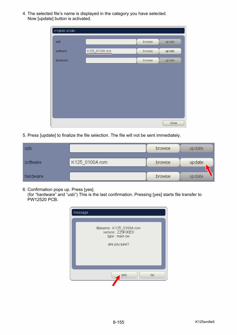
K125sm8e5 8-155
4. The selected file’s name is displayed in the category you have selected. Now [update] button is activated.
5. Press [update] to finalize the file selection. The file will not be sent immediately.
6. Confirmation pops up. Press [yes].
(for “hardware” and “usb”) This is the last confirmation. Pressing [yes] starts file transfer to PW12520 PCB.
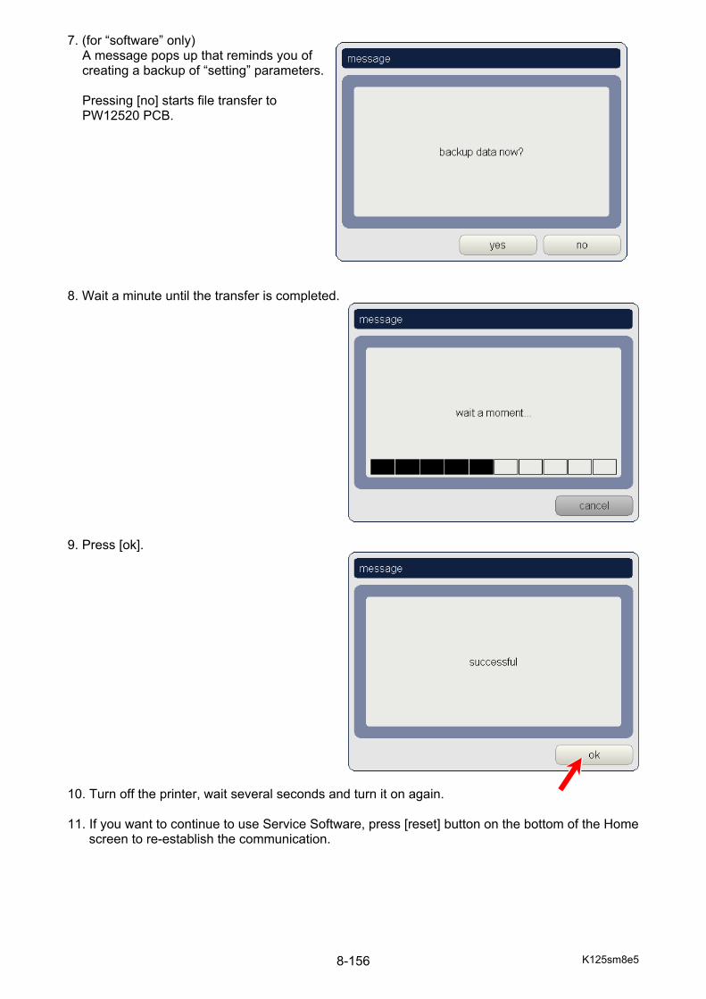
K125sm8e5 8-156
7. (for “software” only) A message pops up that reminds you of creating a backup of “setting” parameters. Pressing [no] starts file transfer to PW12520 PCB.
8. Wait a minute until the transfer is completed.
9. Press [ok].
10. Turn off the printer, wait several seconds and turn it on again. 11. If you want to continue to use Service Software, press [reset] button on the bottom of the Home
screen to re-establish the communication.

K125sm8e5 8-157
8. 4. 10 Change Password It is possible to change the password (PIN) that is used to enter Service Mode. 1. Press to scroll pages to 3/3, and then press [option] [change password]. 2. Enter a new PIN and press [ok]. Note that the system will not ask the current password entry. 3. Enter the new PIN again for confirmation and press [ok]. TIP: change return menu layer It is possible to change how many menu layers to be returned by pressing [cancel] in service mode. Press to scroll pages to 3/3, and then press [option] [menu type]. type 1: Pressing [cancel] is equal to pressing [close] in service mode menu sub window. For example, when you press [cancel] in “fuser” section, the screen will go back to Home with service mode active. type 2: Pressing [cancel] goes back to service mode menu sub window. For example, when you press [cancel] in “fuser” section, you will see service mode menu to select “setting”, “input check”, “backup data”, etc. type 3: Pressing [cancel] goes back to setting subsection sub window. For example, when you press [cancel] in “fuser” section, you will see setting section sub window to select “fuser”, “high voltage”, “printer function”, etc.
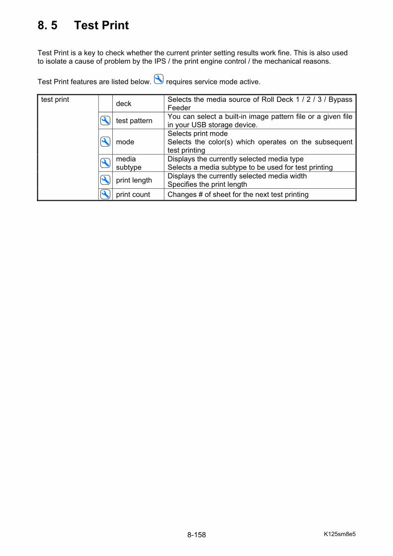
K125sm8e5 8-158
8. 5 Test Print Test Print is a key to check whether the current printer setting results work fine. This is also used to isolate a cause of problem by the IPS / the print engine control / the mechanical reasons.
Test Print features are listed below. requires service mode active. test print deck Selects the media source of Roll Deck 1 / 2 / 3 / Bypass
Feeder
test pattern You can select a built-in image pattern file or a given file in your USB storage device.
mode
Selects print mode Selects the color(s) which operates on the subsequent test printing
media subtype
Displays the currently selected media type Selects a media subtype to be used for test printing
print length Displays the currently selected media width
Specifies the print length print count Changes # of sheet for the next test printing
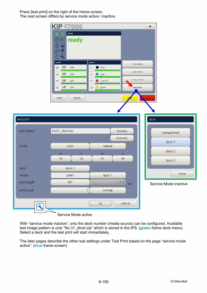
K125sm8e5 8-159
Press [test print] on the right of the Home screen. The next screen differs by service mode active / inactive.
Service Mode inactive Service Mode active With “service mode inactive”, only the deck number (media source) can be configured. Available test image pattern is only “No.31_short.zip” which is stored in the IPS. (green frame deck menu) Select a deck and the test print will start immediately. The later pages describe the other sub settings under Test Print based on the page “service mode active”. (blue frame screen)

K125sm8e5 8-160
Region / Button Function 1 test pattern
file name name of the image pattern file *.zip
2 browse Locates an image pattern file. The default folder is “(K125GUI.exe’s current directory)\testprint”.
3 preview Shows the preview image of currently selected test pattern 4 mode selector Selects the print mode for test printing
monochrome Operates Process Unit K alone color Operates all the 4 Process Units
heavy Operates all the 4 Process Units with heavier media
5 repeat Repeats the selected pattern in the later part of the sheet if the
pattern is smaller than the sheet 6 LED Head activator Enables or disables LED Head(s). When disabled by setting to
"off" the concerning color image is not printed. 7 media source Selects the deck number of Deck 1 / 2 / 3 / bypass feeder 8 media type Shows the currently selected media type
(no switch function here) 9 media subtype Selects a media subtype categorized in the currently selected
type 10 print length Shows the print length by default it is based on the standard
length. Specifies the print length manually
11 print count Sets # of sheet for the test printing 12 print mode Usually “normal” is used to set # of sheet. 13 ok Starts test printing according to the given settings above
1 2
3
4 5
6
7
8 9
10
11 12
13
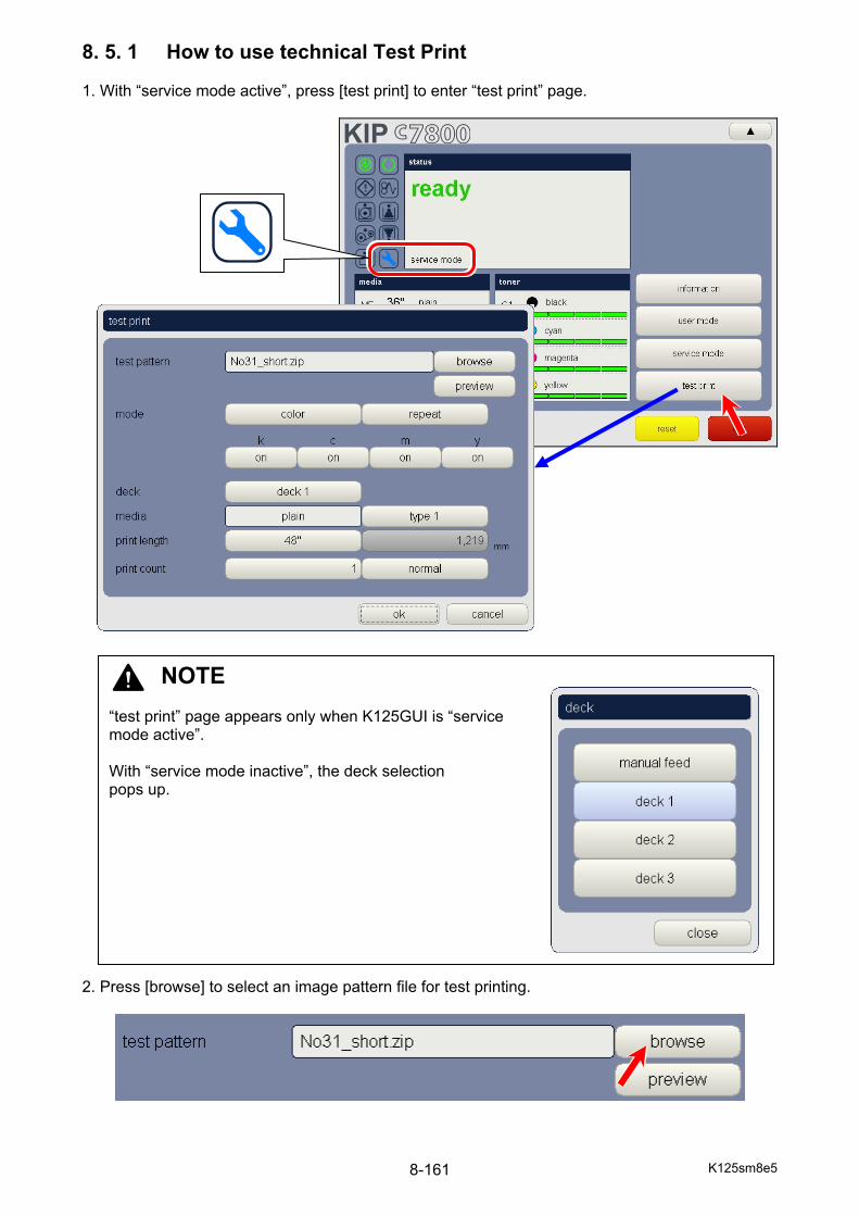
K125sm8e5 8-161
8. 5. 1 How to use technical Test Print 1. With “service mode active”, press [test print] to enter “test print” page.
2. Press [browse] to select an image pattern file for test printing.
NOTE “test print” page appears only when K125GUI is “service mode active”. With “service mode inactive”, the deck selection pops up.
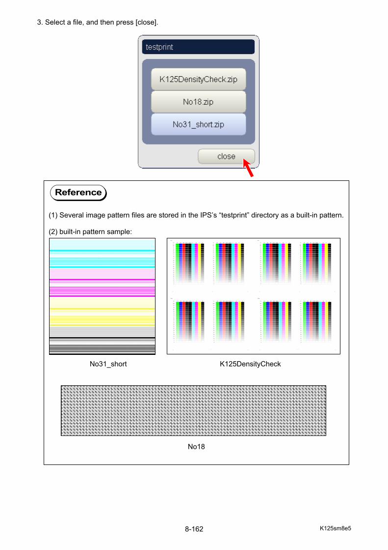
K125sm8e5 8-162
3. Select a file, and then press [close].
Reference
(1) Several image pattern files are stored in the IPS’s “testprint” directory as a built-in pattern. (2) built-in pattern sample:
No31_short K125DensityCheck
No18
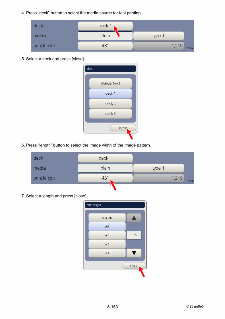
K125sm8e5 8-163
4. Press “deck” button to select the media source for test printing.
5. Select a deck and press [close]. 6. Press “length” button to select the image width of the image pattern.
7. Select a length and press [close].
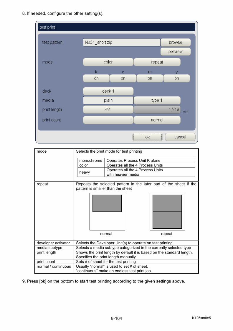
K125sm8e5 8-164
8. If needed, configure the other setting(s).
mode Selects the print mode for test printing
monochrome Operates Process Unit K alone color Operates all the 4 Process Units
heavy Operates all the 4 Process Units with heavier media
repeat Repeats the selected pattern in the later part of the sheet if the
pattern is smaller than the sheet
normal repeat
developer activator Selects the Developer Unit(s) to operate on test printing media subtype Selects a media subtype categorized in the currently selected type print length Shows the print length by default it is based on the standard length.
Specifies the print length manually print count Sets # of sheet for the test printing normal / continuous Usually “normal” is used to set # of sheet.
“continuous” make an endless test print job. 9. Press [ok] on the bottom to start test printing according to the given settings above.

K125sm9e1
Chapter 9
Adjustments
Page 9. 1 Adjusting Optical Density 9- 1 9. 2 Readjustment of Tension Sensor 9-13 9. 3 Belt Skew Adjustment 9-18 9. 3. 1 Before Skew Correction Adjustment 9-18 9. 3. 2 Skew Correction Adjustment 9-25
K125sm9e2 9-1
9. 1 Adjusting Optical Density Density Control is a process to reproduce a satisfactory image quality (called “Target Density”) regardless of the printer’s environment such as temperature condition, by compensating Developer Bias. For further detailed description, see chapter 3. The Target Density has been factory-adjusted. This section describes how to set the “factory default” Target Density in the field, without a backup INI. This procedure requires a roll of 20# Standard Bond, and a densitometer. Readjust CMYK optical densities to the following target values by taking the following (1) to (35).
Color Target densities Bond (EU and NA)
(Example : 20lb bondPlain paper (Asia) (Example : SHNK)
K 0.88 +/-0.03 0.93 +/-0.03 C 0.83 +/-0.03 0.88 +/-0.03 M 0.83 +/-0.03 0.88 +/-0.03 Y 0.68 +/-0.03 0.73 +/-0.03
1. On the Service Software, choose user mode and then choose density control. 2. Set density control to off. (This is important. Make sure to set it to off before starting
adjustment.)
Reference
This section includes a brief operation procedure of the service software. For basic functions and notices excluded in this section, review chapter 8 as needed.
K125sm9e2 9-2
3. On the Service Software, choose service mode and enter the service password 0000 (default) to enter the service mode.
4. Choose setting. 5. Choose high voltage. 6. Check the values of Backup Data No.113 to 116 (developer roller bias), and confirm that
they are set to the following starting values. (If not, please set to the following values manually.)
BUD No. Standard K developer roller bias (process #1) 0113 190
C developer roller bias (process #2) 0114 180
M developer roller bias (process #3) 0115 195
Y developer roller bias (process #4) 0116 180
190
180
195
180
K125sm9e2 9-3
7. On the Service Software, choose as [service mode] - [setting] - [print density]. 8. Manually set all Backup Data No.801 to 812 (light intensity correction) to the following
starting values (130).
BUD No. Standard K Light intensity correction (process #1 led head #1) 0801 130
K Light intensity correction (process #1 led head #2) 0802 130
K Light intensity correction (process #1 led head #3) 0803 130
C Light intensity correction (process #2 led head #1) 0804 130
C Light intensity correction (process #2 led head #2) 0805 130
C Light intensity correction (process #2 led head #3) 0806 130
M Light intensity correction (process #3 led head #1) 0807 130
M Light intensity correction (process #3 led head #2) 0808 130
M Light intensity correction (process #3 led head #3) 0809 130
Y Light intensity correction (process #4 led head #1) 0810 130
Y Light intensity correction (process #4 led head #2) 0811 130
Y Light intensity correction (process #4 led head #3) 0812 130
K125sm9e2 9-4
9. On the Service Software, choose as [service mode] - [setting] - [print density]. 10. Check the values of Backup Data No.813 to 816 (light gain), and confirm that they are set to
the following starting values. (If not, please set to the following values manually.)
BUD No. Standard K light gain (process #1) 813 100
C light gain (process #2) 814 100
M light gain (process #3) 815 100
Y light gain (process #4) 816 100 11. Set a 36” wide roll media (bond or plain paper) to the printer.

K125sm9e2 9-5
12. On the Service Software, choose test print. 13. Press browse and select No31_short.zip in the list. (This is the test pattern No.31) 14. Print this pattern by 36”x48” with bond or plain paper. Test pattern No.31 15. Each color consists of 23 different types of images. Please find the 18th image from the top in
each color, which is to be used to balance the densities among 3 image blocks. 18th image (used for balancing the densities among 3 blocks)
1 2 3 4 5 6 7 8 9 10 11 12 13 14151617 18
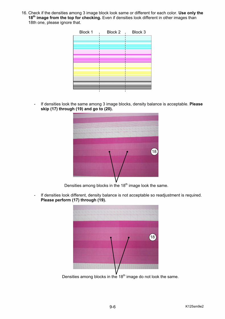
K125sm9e2 9-6
16. Check if the densities among 3 image block look same or different for each color. Use only the 18th image from the top for checking. Even if densities look different in other images than 18th one, please ignore that.
Block 1 Block 2 Block 3
- If densities look the same among 3 image blocks, density balance is acceptable. Please skip (17) through (19) and go to (20).
Densities among blocks in the 18th image look the same.
- If densities look different, density balance is not acceptable so readjustment is required. Please perform (17) through (19).
Densities among blocks in the 18th image do not look the same.
18
18
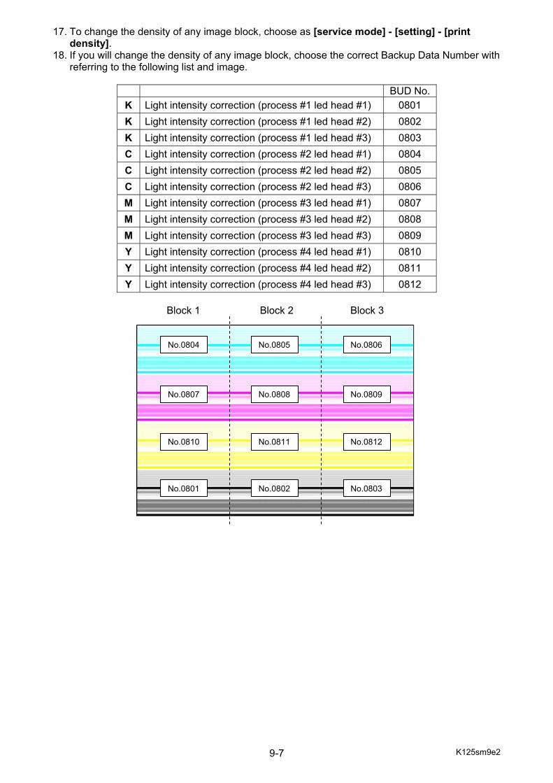
K125sm9e2 9-7
17. To change the density of any image block, choose as [service mode] - [setting] - [print density].
18. If you will change the density of any image block, choose the correct Backup Data Number with referring to the following list and image.
BUD No.
K Light intensity correction (process #1 led head #1) 0801 K Light intensity correction (process #1 led head #2) 0802 K Light intensity correction (process #1 led head #3) 0803 C Light intensity correction (process #2 led head #1) 0804 C Light intensity correction (process #2 led head #2) 0805 C Light intensity correction (process #2 led head #3) 0806 M Light intensity correction (process #3 led head #1) 0807 M Light intensity correction (process #3 led head #2) 0808 M Light intensity correction (process #3 led head #3) 0809 Y Light intensity correction (process #4 led head #1) 0810 Y Light intensity correction (process #4 led head #2) 0811 Y Light intensity correction (process #4 led head #3) 0812
Block 1 Block 2 Block 3
No.0801 No.0802 No.0803
No.0804 No.0805 No.0806
No.0807 No.0808 No.0809
No.0810 No.0811 No.0812
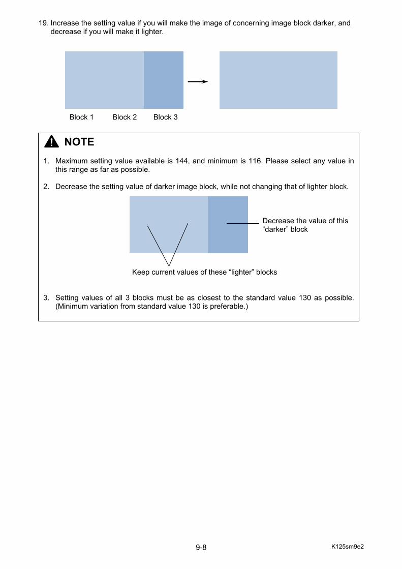
K125sm9e2 9-8
19. Increase the setting value if you will make the image of concerning image block darker, and decrease if you will make it lighter.
Block 1 Block 2 Block 3
NOTE 1. Maximum setting value available is 144, and minimum is 116. Please select any value in
this range as far as possible. 2. Decrease the setting value of darker image block, while not changing that of lighter block. Decrease the value of this “darker” block Keep current values of these “lighter” blocks 3. Setting values of all 3 blocks must be as closest to the standard value 130 as possible.
(Minimum variation from standard value 130 is preferable.)
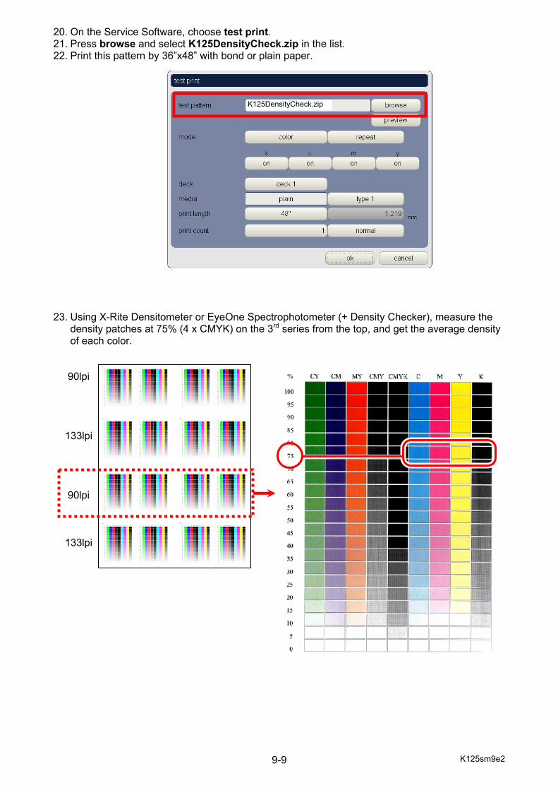
K125sm9e2 9-9
20. On the Service Software, choose test print. 21. Press browse and select K125DensityCheck.zip in the list. 22. Print this pattern by 36”x48” with bond or plain paper. 23. Using X-Rite Densitometer or EyeOne Spectrophotometer (+ Density Checker), measure the
density patches at 75% (4 x CMYK) on the 3rd series from the top, and get the average density of each color.
90lpi 133lpi 90lpi 133lpi
K125DensityCheck.zip
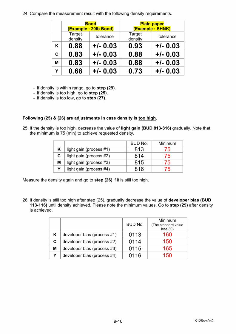
K125sm9e2 9-10
24. Compare the measurement result with the following density requirements.
Bond (Example : 20lb Bond)
Plain paper (Example : SHNK)
Target density tolerance Target
density tolerance
K 0.88 +/- 0.03 0.93 +/- 0.03 C 0.83 +/- 0.03 0.88 +/- 0.03 M 0.83 +/- 0.03 0.88 +/- 0.03 Y 0.68 +/- 0.03 0.73 +/- 0.03
- If density is within range, go to step (29). - If density is too high, go to step (25). - If density is too low, go to step (27).
Following (25) & (26) are adjustments in case density is too high. 25. If the density is too high, decrease the value of light gain (BUD 813-816) gradually. Note that
the minimum is 75 (min) to achieve requested density.
BUD No. Minimum K light gain (process #1) 813 75 C light gain (process #2) 814 75 M light gain (process #3) 815 75 Y light gain (process #4) 816 75
Measure the density again and go to step (26) if it is still too high. 26. If density is still too high after step (25), gradually decrease the value of developer bias (BUD
113-116) until density achieved. Please note the minimum values. Go to step (29) after density is achieved.
BUD No. Minimum
(The standard value less 30)
K developer bias (process #1) 0113 160 C developer bias (process #2) 0114 150 M developer bias (process #3) 0115 165 Y developer bias (process #4) 0116 150
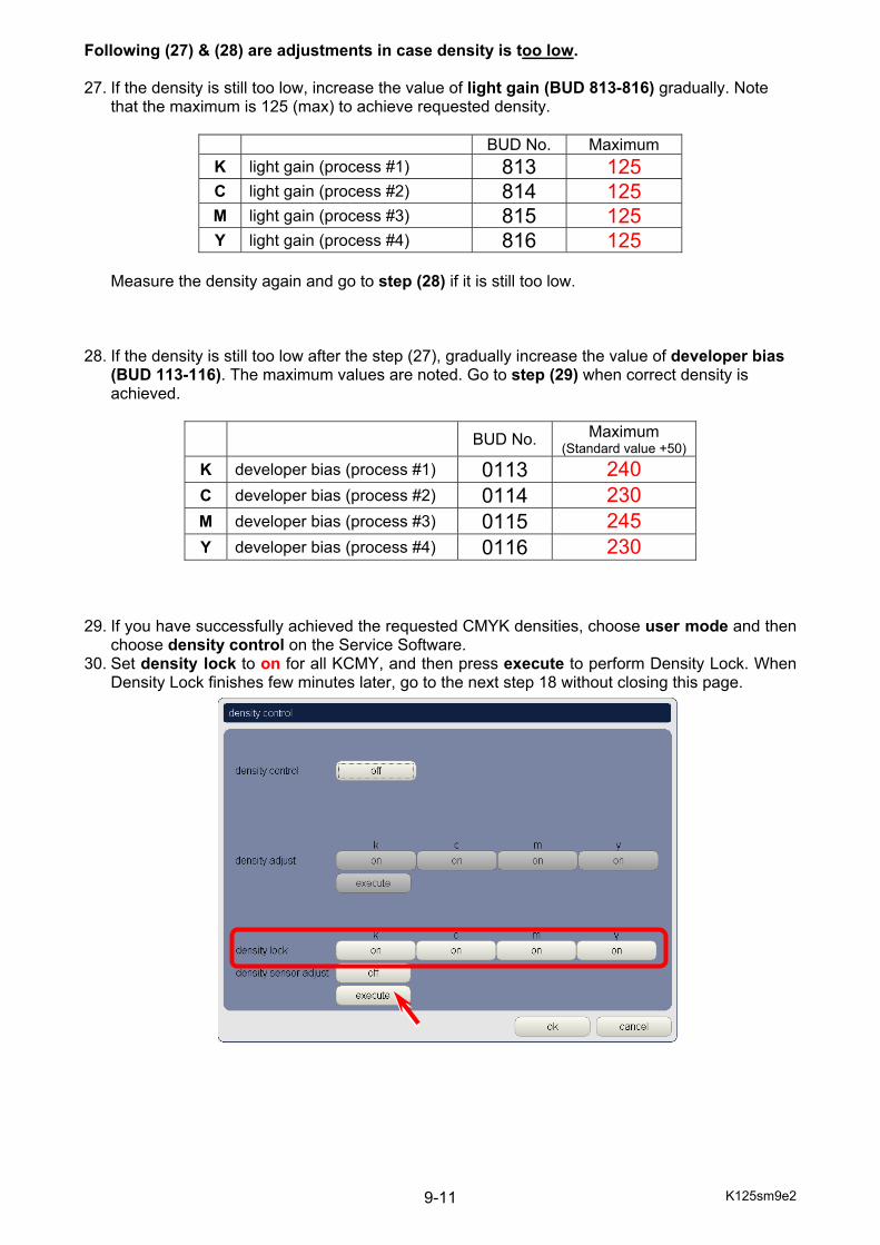
K125sm9e2 9-11
Following (27) & (28) are adjustments in case density is too low. 27. If the density is still too low, increase the value of light gain (BUD 813-816) gradually. Note
that the maximum is 125 (max) to achieve requested density.
BUD No. Maximum K light gain (process #1) 813 125 C light gain (process #2) 814 125 M light gain (process #3) 815 125 Y light gain (process #4) 816 125
Measure the density again and go to step (28) if it is still too low.
28. If the density is still too low after the step (27), gradually increase the value of developer bias
(BUD 113-116). The maximum values are noted. Go to step (29) when correct density is achieved.
BUD No. Maximum
(Standard value +50) K developer bias (process #1) 0113 240 C developer bias (process #2) 0114 230 M developer bias (process #3) 0115 245 Y developer bias (process #4) 0116 230
29. If you have successfully achieved the requested CMYK densities, choose user mode and then
choose density control on the Service Software. 30. Set density lock to on for all KCMY, and then press execute to perform Density Lock. When
Density Lock finishes few minutes later, go to the next step 18 without closing this page.
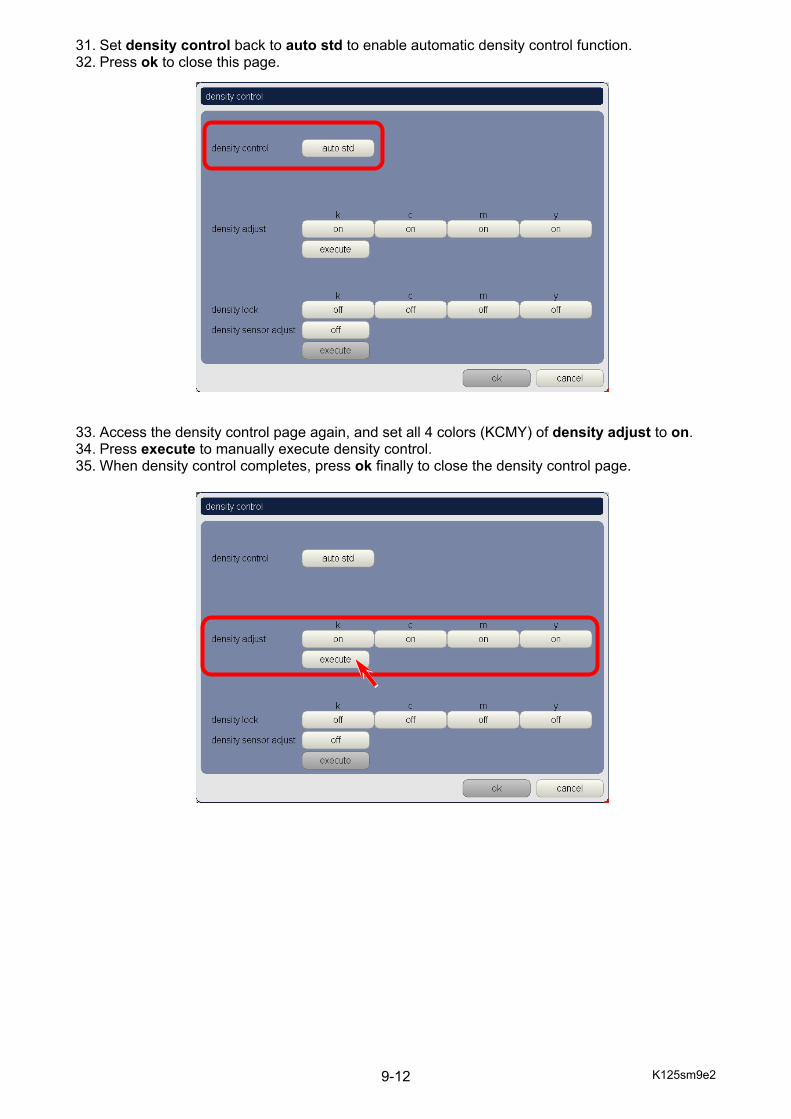
K125sm9e2 9-12
31. Set density control back to auto std to enable automatic density control function. 32. Press ok to close this page. 33. Access the density control page again, and set all 4 colors (KCMY) of density adjust to on. 34. Press execute to manually execute density control. 35. When density control completes, press ok finally to close the density control page.

K125sm9e3 9-13
9. 2 Readjustment of Tension Sensor The distance between Tension Sensor and Arm should be decided according to the output voltage from Tension Sensor. After replacing Tension Sensor, checking the output voltage with using a multimeter is required in order to adjust positioning.
NOTE The Bracket 34 on the right next to the Sensor Bracket is a stopper for Fuser Entrance Guide. Never loosen the screw on the Bracket 34.
Tension Sensor
Arm
Bracket 34 Screw
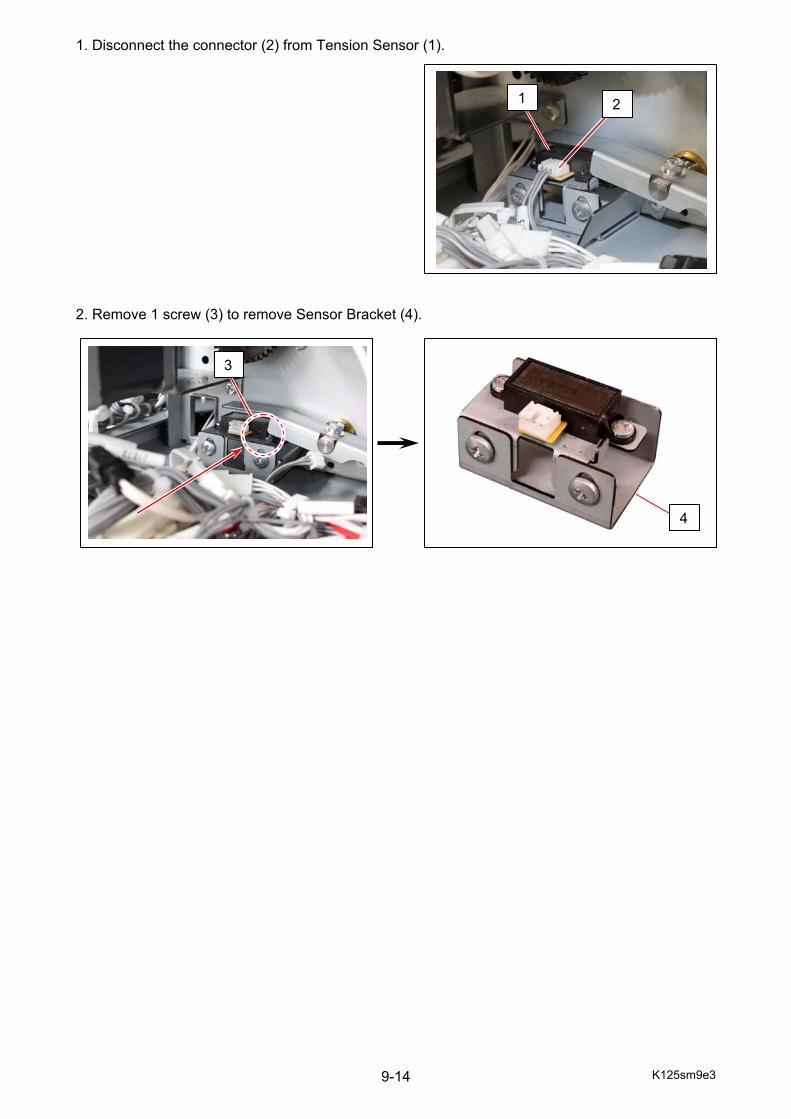
K125sm9e3 9-14
1. Disconnect the connector (2) from Tension Sensor (1). 2. Remove 1 screw (3) to remove Sensor Bracket (4).
2 1
3
4
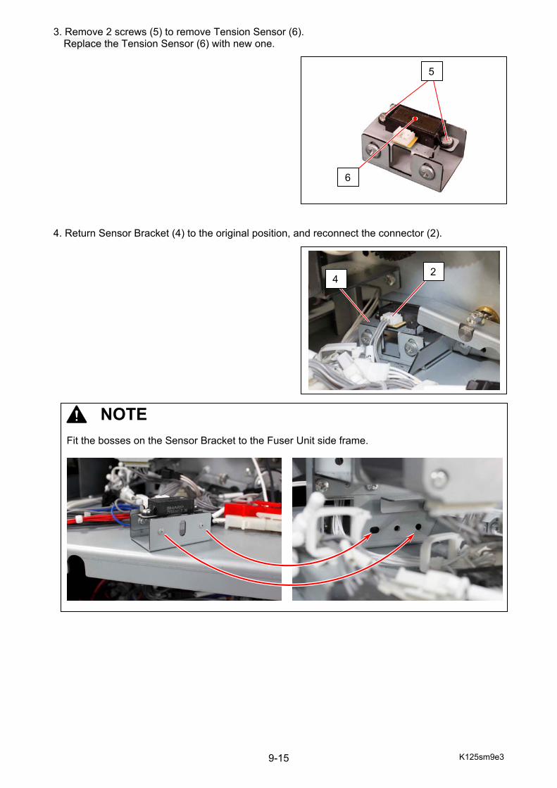
K125sm9e3 9-15
3. Remove 2 screws (5) to remove Tension Sensor (6). Replace the Tension Sensor (6) with new one.
4. Return Sensor Bracket (4) to the original position, and reconnect the connector (2).
NOTE
Fit the bosses on the Sensor Bracket to the Fuser Unit side frame.
2 4
5
6
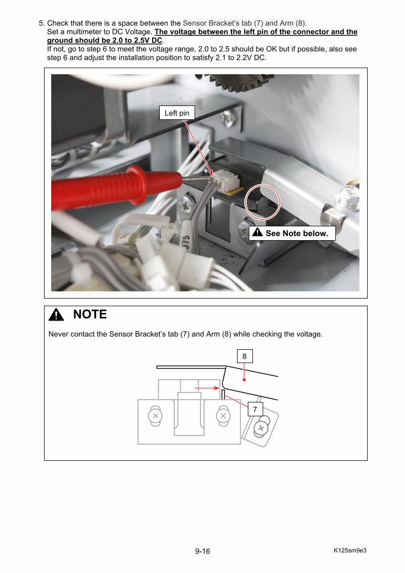
K125sm9e3 9-16
5. Check that there is a space between the Sensor Bracket’s tab (7) and Arm (8). Set a multimeter to DC Voltage. The voltage between the left pin of the connector and the ground should be 2.0 to 2.5V DC. If not, go to step 6 to meet the voltage range. 2.0 to 2.5 should be OK but if possible, also see step 6 and adjust the installation position to satisfy 2.1 to 2.2V DC.
Left pin
NOTE Never contact the Sensor Bracket’s tab (7) and Arm (8) while checking the voltage.
See Note below.
8
7
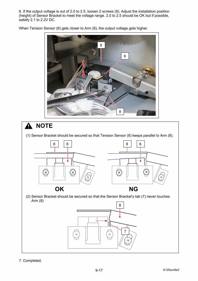
K125sm9e3 9-17
6. If the output voltage is out of 2.0 to 2.5, loosen 2 screws (9). Adjust the installation position (height) of Sensor Bracket to meet the voltage range. 2.0 to 2.5 should be OK but if possible, satisfy 2.1 to 2.2V DC. When Tension Sensor (6) gets closer to Arm (8), the output voltage gets higher. 7. Completed.
9
NOTE (1) Sensor Bracket should be secured so that Tension Sensor (6) keeps parallel to Arm (8).
(2) Sensor Bracket should be secured so that the Sensor Bracket’s tab (7) never touches Arm (8)
8
OK
6 8
NG
8 6
8
7
6

K125sm9e4 9-18
9. 3 Belt Skew Adjustment
9. 3. 1 Before Skew Correction Adjustment There are 3 possible causes of Belt Skew Error listed below.
(1) Re-confirm the leveling. The KIP c7800 requires a quite precise level. Poor leveling may cause Belt Skew. Re-confirm the leveling, and try leveling again if necessary.
(2) Clean Belt inner surface and Skew Correction Roller. Toner / oil dirt sticking on some areas listed below may cause Belt Skew. - Outside circumferences of the inner surface on both Belt rims - On the flared end part of the Skew Correction Roller Even slight amount of the nature oil on your hand would do. Wipe the said areas with an alcohol-moistured cloth.
(3) Check for smooth movement of Skew Correction Roller. If the Skew Correction Roller’s movement is not enough smooth when the roller is tensioned/released, it may cause Belt Skew. Checking procedure is shown on the next page.
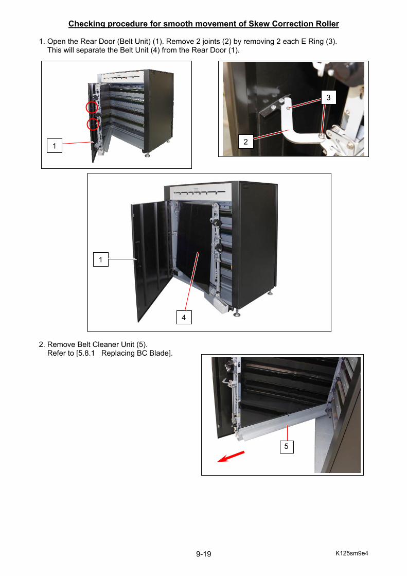
K125sm9e4 9-19
Checking procedure for smooth movement of Skew Correction Roller 1. Open the Rear Door (Belt Unit) (1). Remove 2 joints (2) by removing 2 each E Ring (3). This will separate the Belt Unit (4) from the Rear Door (1). 2. Remove Belt Cleaner Unit (5). Refer to [5.8.1 Replacing BC Blade].
2
1
4
1
3
5

K125sm9e4 9-20
3. Remove the screw (6) to unfix the Tension Roller Assembly (7). 4. Rotate the Tension Roller Assembly (7) clockwise, and fix it at “release position” by the screw
(6) which is to be put into another screw hole. This will unfasten the Belt.
6
7
6
7
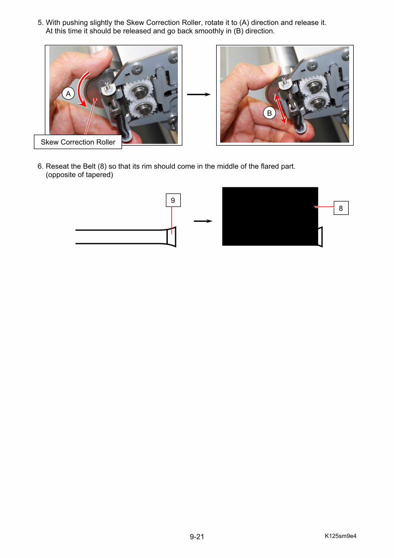
K125sm9e4 9-21
5. With pushing slightly the Skew Correction Roller, rotate it to (A) direction and release it. At this time it should be released and go back smoothly in (B) direction. 6. Reseat the Belt (8) so that its rim should come in the middle of the flared part. (opposite of tapered)
A
Skew Correction Roller
B
98
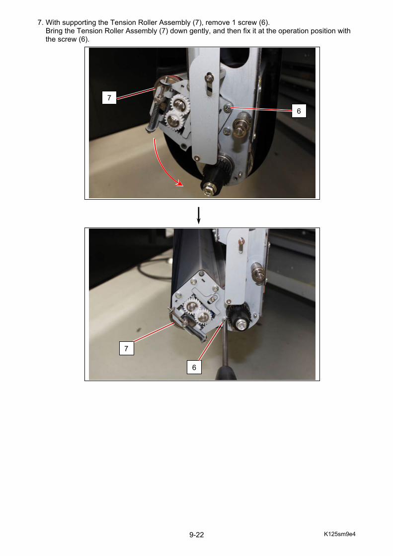
K125sm9e4 9-22
7. With supporting the Tension Roller Assembly (7), remove 1 screw (6). Bring the Tension Roller Assembly (7) down gently, and then fix it at the operation position with
the screw (6).
6
7
6
7
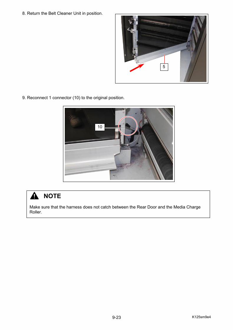
K125sm9e4 9-23
8. Return the Belt Cleaner Unit in position. 9. Reconnect 1 connector (10) to the original position.
5
10
NOTE Make sure that the harness does not catch between the Rear Door and the Media Charge Roller.
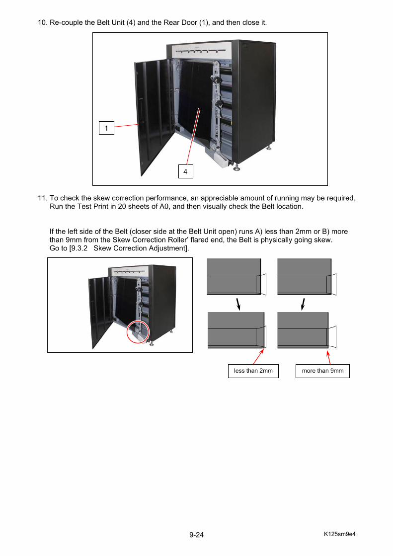
K125sm9e4 9-24
10. Re-couple the Belt Unit (4) and the Rear Door (1), and then close it. 11. To check the skew correction performance, an appreciable amount of running may be required. Run the Test Print in 20 sheets of A0, and then visually check the Belt location.
If the left side of the Belt (closer side at the Belt Unit open) runs A) less than 2mm or B) more than 9mm from the Skew Correction Roller’ flared end, the Belt is physically going skew. Go to [9.3.2 Skew Correction Adjustment].
4
1
less than 2mm more than 9mm
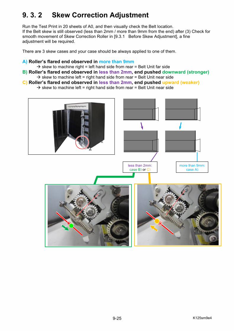
K125sm9e4 9-25
9. 3. 2 Skew Correction Adjustment Run the Test Print in 20 sheets of A0, and then visually check the Belt location. If the Belt skew is still observed (less than 2mm / more than 9mm from the end) after (3) Check for smooth movement of Skew Correction Roller in [9.3.1 Before Skew Adjustment], a fine adjustment will be required. There are 3 skew cases and your case should be always applied to one of them. A) Roller’s flared end observed in more than 9mm skew to machine right = left hand side from rear = Belt Unit far side B) Roller’s flared end observed in less than 2mm, end pushed downward (stronger) skew to machine left = right hand side from rear = Belt Unit near side C) Roller’s flared end observed in less than 2mm, end pushed upward (weaker) skew to machine left = right hand side from rear = Belt Unit near side
less than 2mm: case B) or C)
more than 9mm: case A)
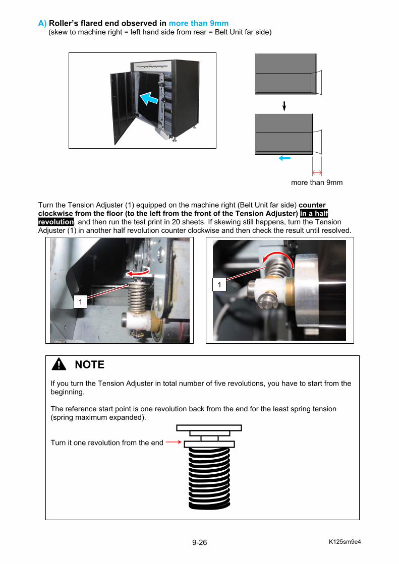
K125sm9e4 9-26
A) Roller’s flared end observed in more than 9mm (skew to machine right = left hand side from rear = Belt Unit far side)
Turn the Tension Adjuster (1) equipped on the machine right (Belt Unit far side) counter clockwise from the floor (to the left from the front of the Tension Adjuster) in a half revolution, and then run the test print in 20 sheets. If skewing still happens, turn the Tension Adjuster (1) in another half revolution counter clockwise and then check the result until resolved.
more than 9mm
1
NOTE If you turn the Tension Adjuster in total number of five revolutions, you have to start from the beginning. The reference start point is one revolution back from the end for the least spring tension (spring maximum expanded). Turn it one revolution from the end
1
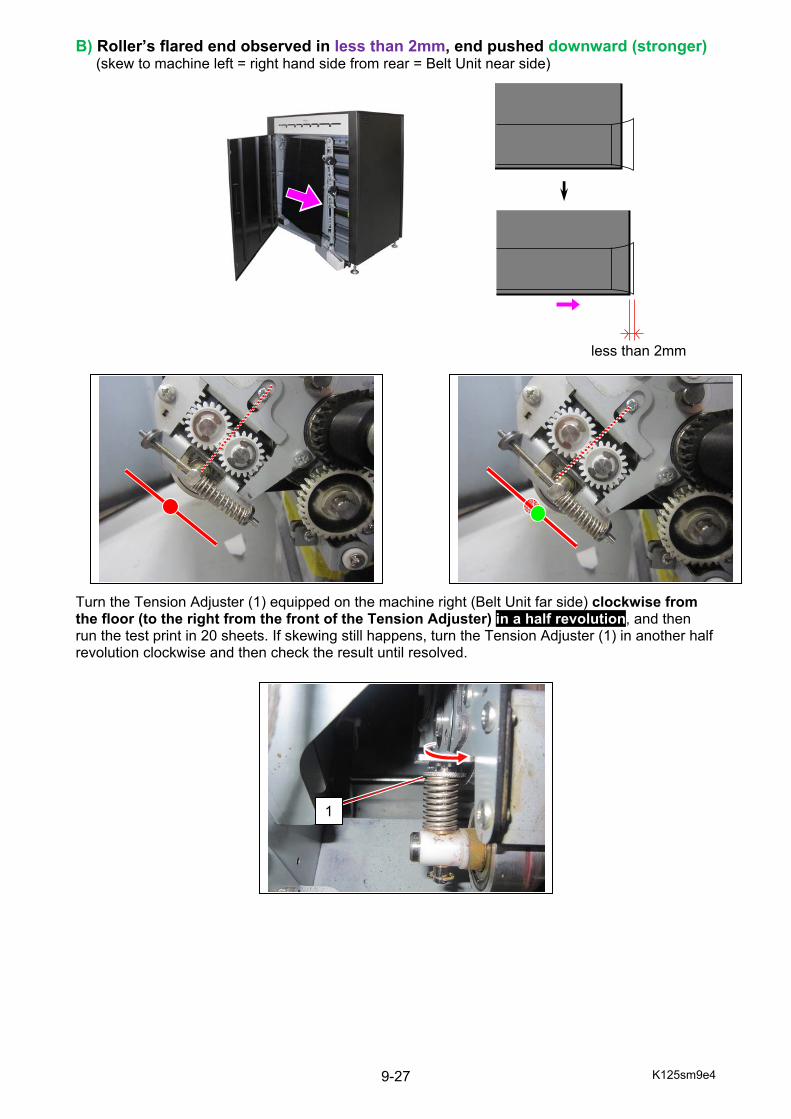
K125sm9e4 9-27
B) Roller’s flared end observed in less than 2mm, end pushed downward (stronger) (skew to machine left = right hand side from rear = Belt Unit near side) Turn the Tension Adjuster (1) equipped on the machine right (Belt Unit far side) clockwise from the floor (to the right from the front of the Tension Adjuster) in a half revolution, and then run the test print in 20 sheets. If skewing still happens, turn the Tension Adjuster (1) in another half revolution clockwise and then check the result until resolved.
less than 2mm
1
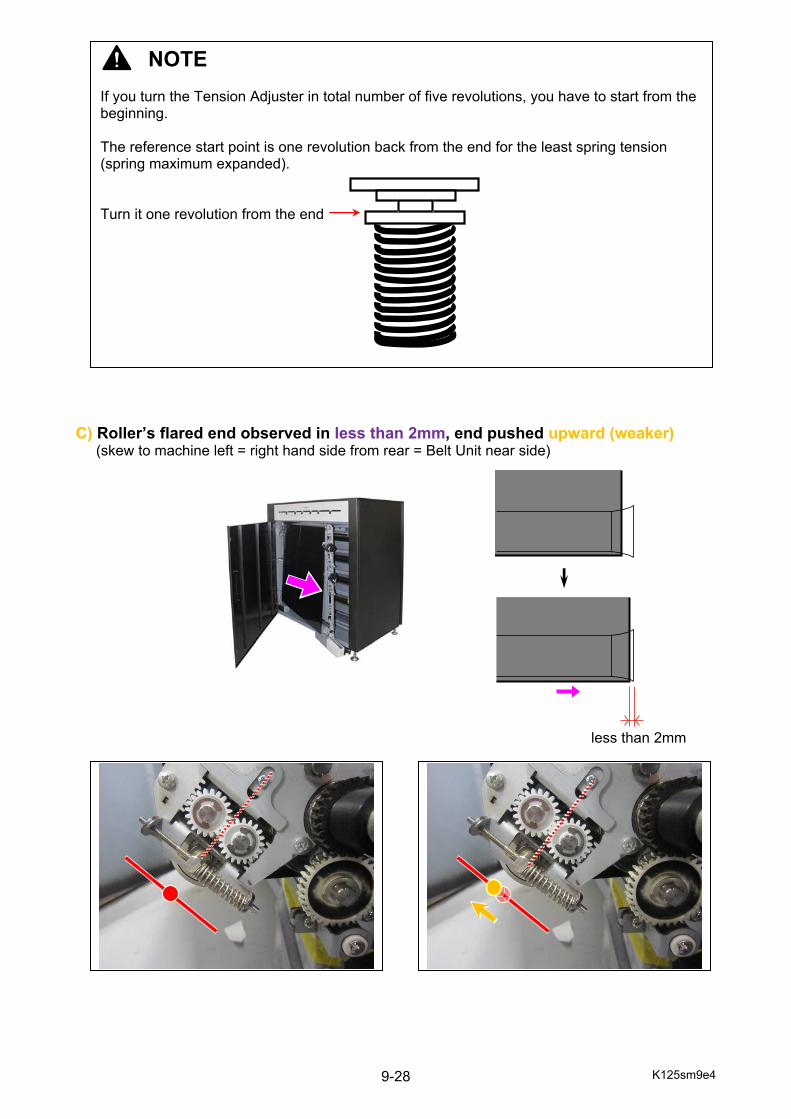
K125sm9e4 9-28
C) Roller’s flared end observed in less than 2mm, end pushed upward (weaker) (skew to machine left = right hand side from rear = Belt Unit near side)
NOTE If you turn the Tension Adjuster in total number of five revolutions, you have to start from the beginning. The reference start point is one revolution back from the end for the least spring tension (spring maximum expanded). Turn it one revolution from the end
less than 2mm
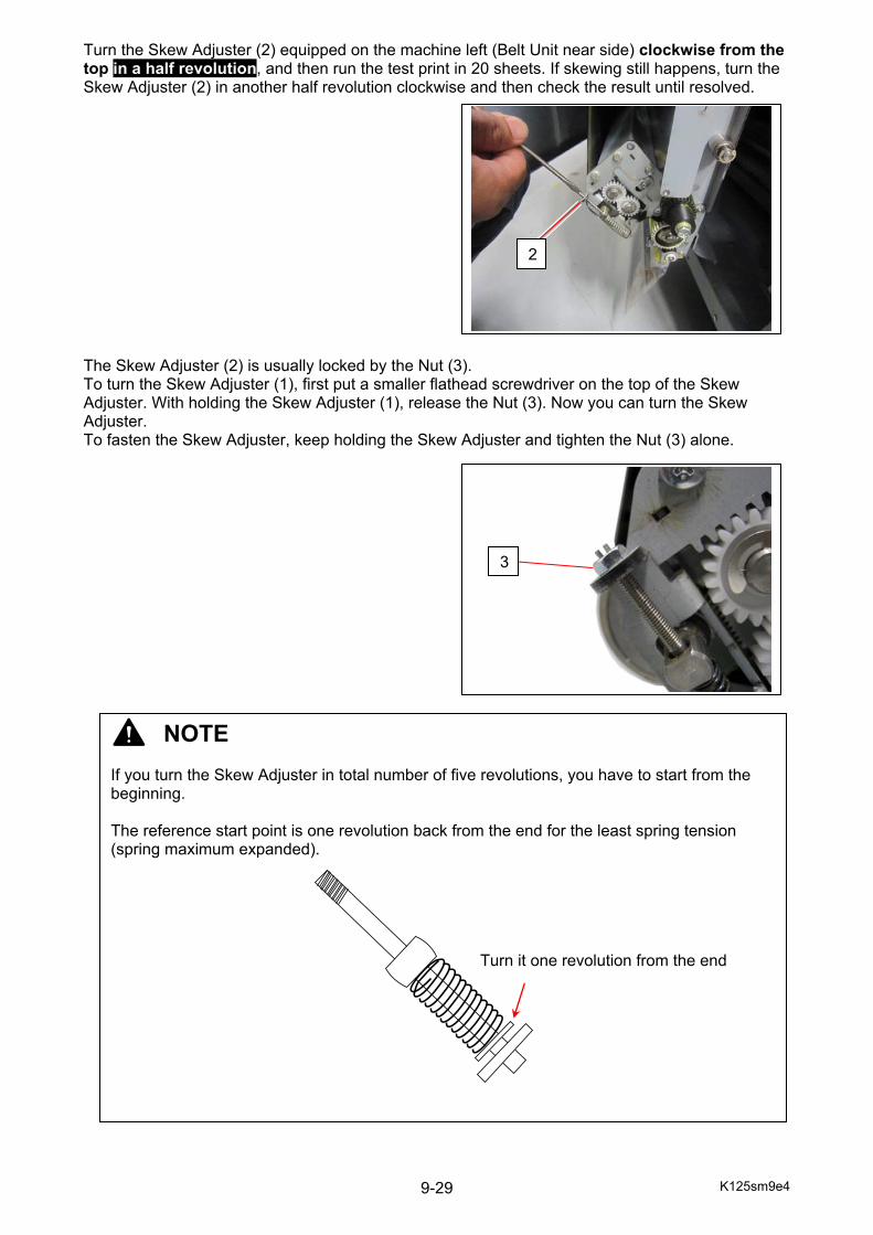
K125sm9e4 9-29
Turn the Skew Adjuster (2) equipped on the machine left (Belt Unit near side) clockwise from the top in a half revolution, and then run the test print in 20 sheets. If skewing still happens, turn the Skew Adjuster (2) in another half revolution clockwise and then check the result until resolved. The Skew Adjuster (2) is usually locked by the Nut (3). To turn the Skew Adjuster (1), first put a smaller flathead screwdriver on the top of the Skew Adjuster. With holding the Skew Adjuster (1), release the Nut (3). Now you can turn the Skew Adjuster. To fasten the Skew Adjuster, keep holding the Skew Adjuster and tighten the Nut (3) alone.
NOTE If you turn the Skew Adjuster in total number of five revolutions, you have to start from the beginning. The reference start point is one revolution back from the end for the least spring tension (spring maximum expanded). Turn it one revolution from the end
2
3

K125sm10e1
Chapter 10
Appendix
PRIMARYCircuit Diagram
KIP C7800
SECONDARY Circuit Diagram
KIP C7800