Kinetic plasma microinstabilities Gentle beam instability Ion- and electron-acoustic instability...
22
Kinetic plasma microinstabilities • Gentle beam instability • Ion- and electron-acoustic instability • Current-driven cyclotron instability • Loss-cone instabilities • Anisotropy-driven waves • Ion beam instabilities • Cyclotron maser instability
-
Upload
rolf-stephens -
Category
Documents
-
view
231 -
download
2
Transcript of Kinetic plasma microinstabilities Gentle beam instability Ion- and electron-acoustic instability...
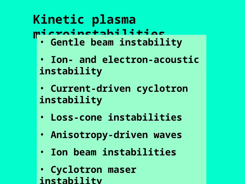
Kinetic plasma microinstabilities
• Gentle beam instability
• Ion- and electron-acoustic instability
• Current-driven cyclotron instability
• Loss-cone instabilities
• Anisotropy-driven waves
• Ion beam instabilities
• Cyclotron maser instability
• Drift-wave instability
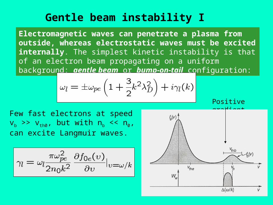
Gentle beam instability I
Electromagnetic waves can penetrate a plasma from outside, whereas electrostatic waves must be excited internally. The simplest kinetic instability is that of an electron beam propagating on a uniform background: gentle beam or bump-on-tail configuration:
Positive gradient
Few fast electrons at speed vb >> vth0, but with nb << n0, can excite Langmuir waves.
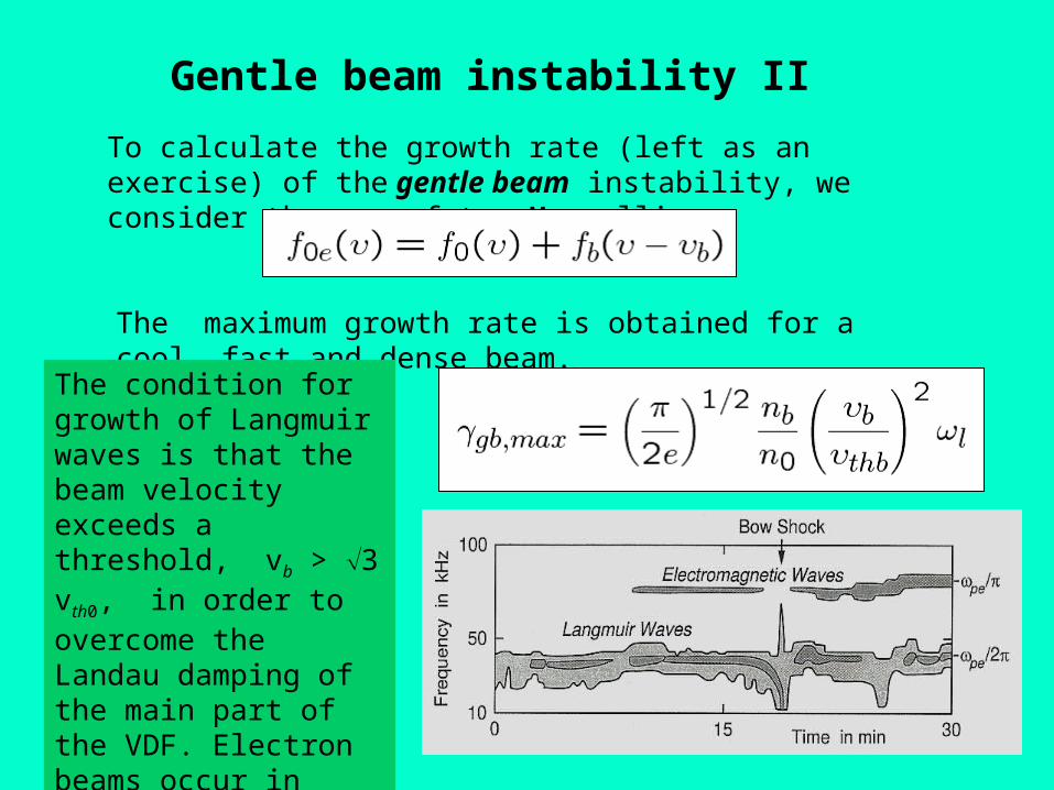
Gentle beam instability II
To calculate the growth rate (left as an exercise) of the gentle beam instability, we consider the sum of two Maxwellians:
The maximum growth rate is obtained for a cool, fast and dense beam.
The condition for growth of Langmuir waves is that the beam velocity exceeds a threshold, vb > 3 vth0, in order to overcome the Landau damping of the main part of the VDF. Electron beams occur in front of the bow shock and often in the solar corona during solar flares.
Ion-acoustic instability I
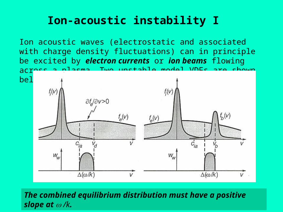
Ion acoustic waves (electrostatic and associated with charge density fluctuations) can in principle be excited by electron currents or ion beams flowing across a plasma. Two unstable model VDFs are shown below.
The combined equilibrium distribution must have a positive slope at /k.
Ion-acoustic instability II
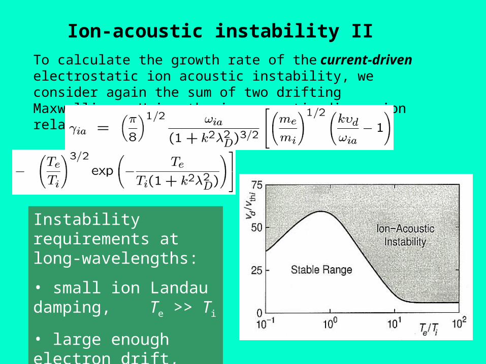
To calculate the growth rate of the current-driven electrostatic ion acoustic instability, we consider again the sum of two drifting Maxwellians. Using the ion-acoustic dispersion relation yields the growth rate:
Instability requirements at long-wavelengths:
• small ion Landau damping, Te >> Ti
• large enough electron drift, vd >> cia
Electron-acoustic instability
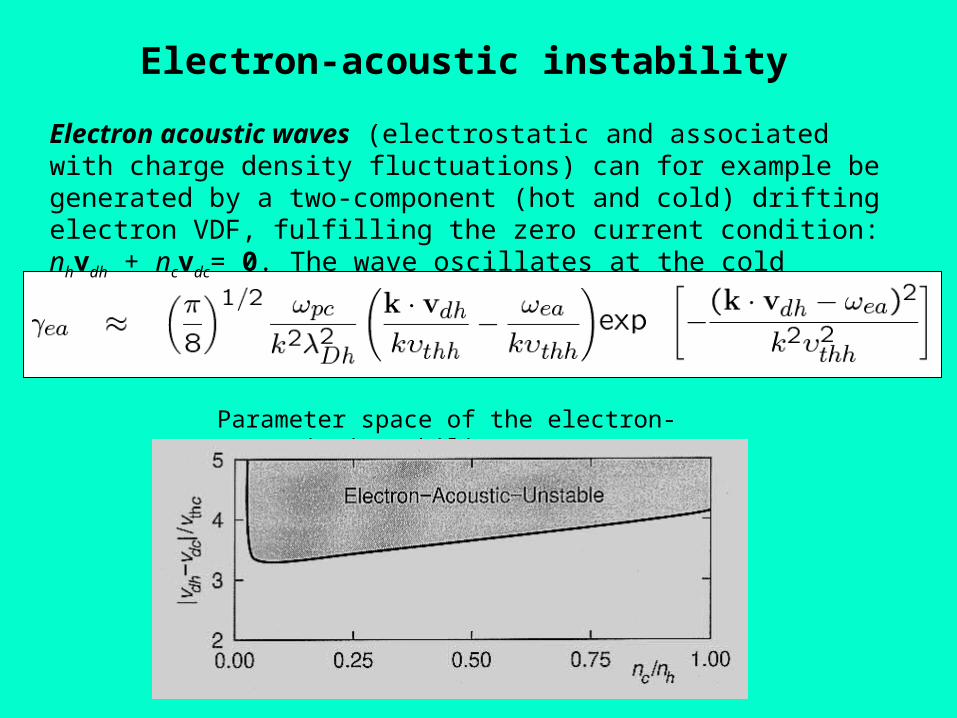
Electron acoustic waves (electrostatic and associated with charge density fluctuations) can for example be generated by a two-component (hot and cold) drifting electron VDF, fulfilling the zero current condition: nhvdh + ncvdc= 0. The wave oscillates at the cold electron plasma frequency, ea pc. Growth rate:
Parameter space of the electron-acoustic instability
Current-driven cyclotron instabilities
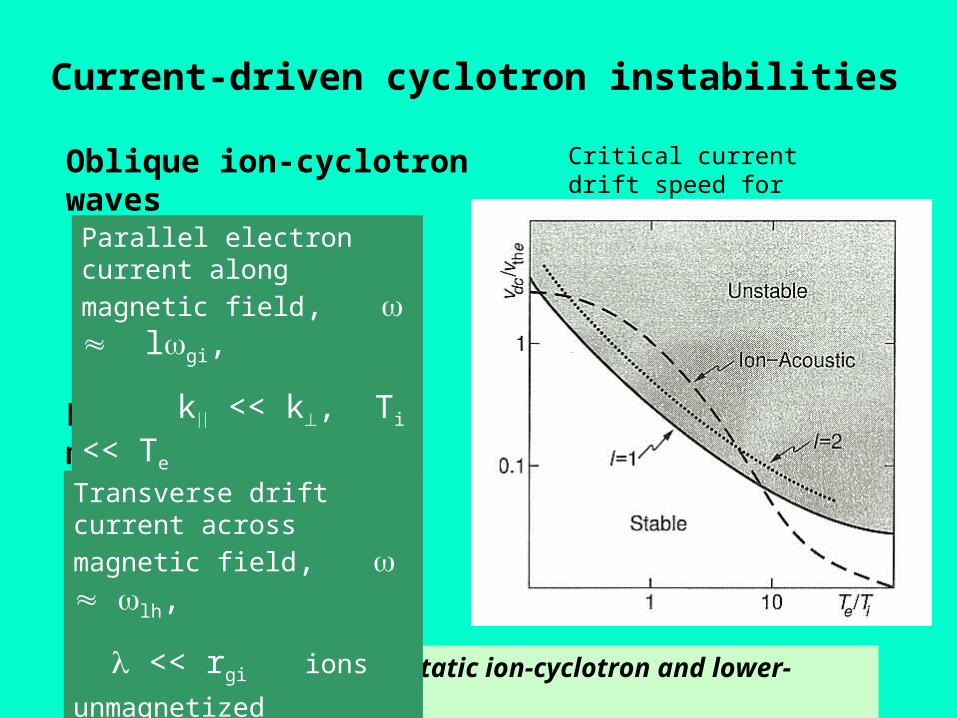
Currents can drive electrostatic ion-cyclotron and lower-hybrid modes.
Oblique ion-cyclotron waves
Lower-hybrid modes
Critical current drift speed for the ion-cyclotron wave
Parallel electron current along
magnetic field, lgi,
k << k, Ti << Te
Transverse drift current across
magnetic field, lh,
<< rgi ions unmagnetized
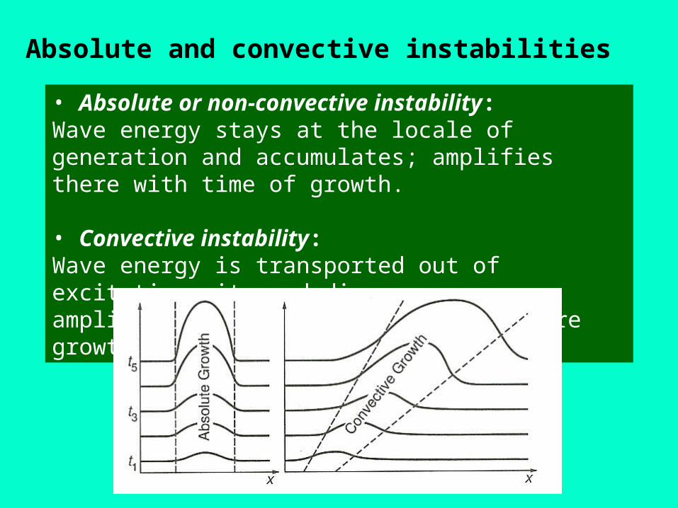
Absolute and convective instabilities
• Absolute or non-convective instability:Wave energy stays at the locale of generation and accumulates; amplifies there with time of growth.
• Convective instability:Wave energy is transported out of excitation site and disperses;amplifies only over that distance where growth rate is positive.
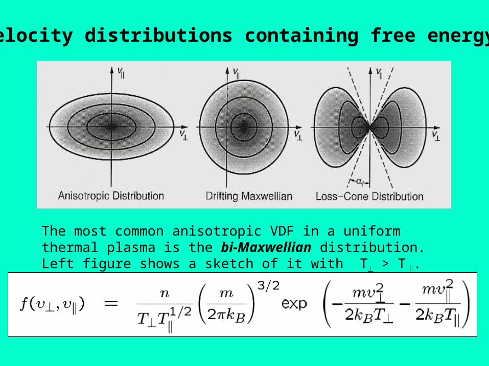
Velocity distributions containing free energy
The most common anisotropic VDF in a uniform thermal plasma is the bi-Maxwellian distribution. Left figure shows a sketch of it with T > T .
Loss-cone instabilities
Electrostatic electron- and ion-cyclotron waves are very important electrostatic waves, because they occur at principle plasma resonances,
• contribute substantially to wave-particle energy exchange
• are purely of kinetic origin
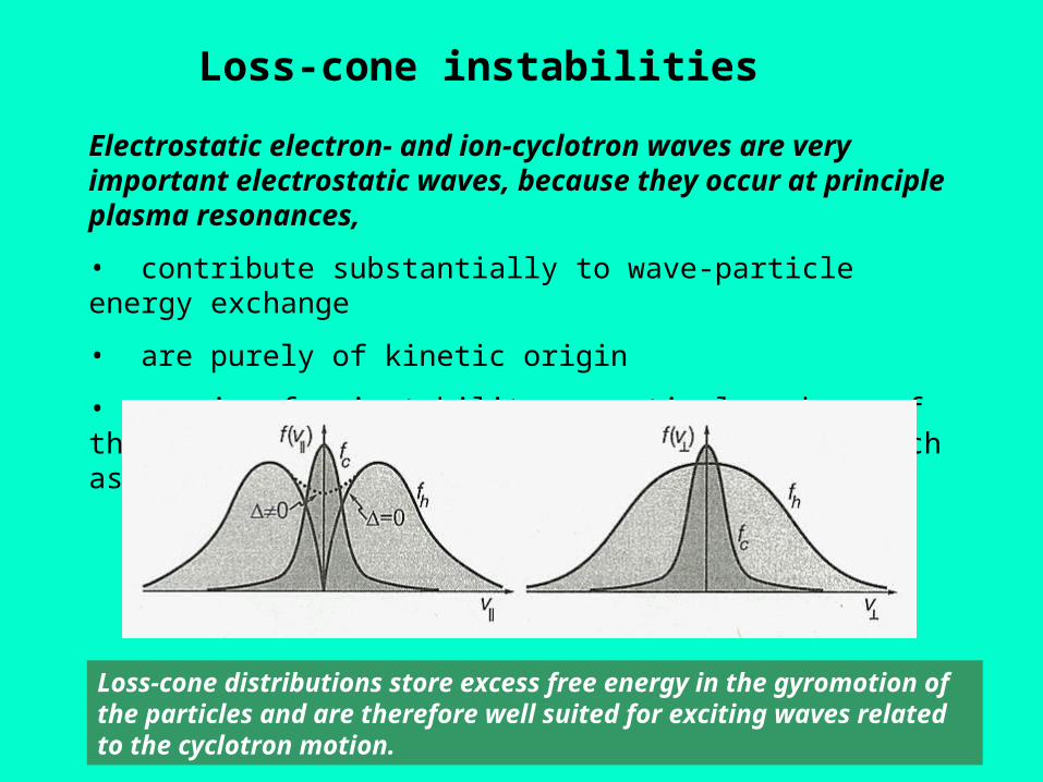
• require for instability a particular shape of the VDF, with enhanced perpendicular energy, such as thermal anisotropy or a loss-cone
Loss-cone distributions store excess free energy in the gyromotion of the particles and are therefore well suited for exciting waves related to the cyclotron motion.
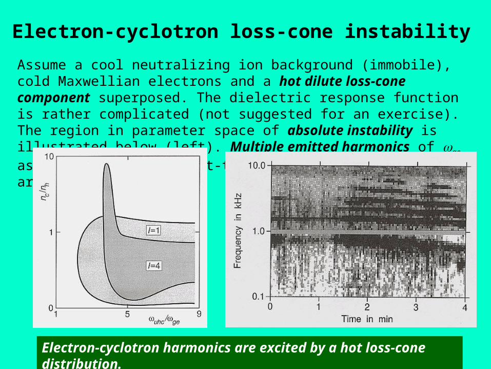
Electron-cyclotron loss-cone instability
Electron-cyclotron harmonics are excited by a hot loss-cone distribution.
Assume a cool neutralizing ion background (immobile), cold Maxwellian electrons and a hot dilute loss-cone component superposed. The dielectric response function is rather complicated (not suggested for an exercise). The region in parameter space of absolute instability is illustrated below (left). Multiple emitted harmonics of ge as observed in the night-time equatorial magnetosphere are shown on the right.
Ion-cyclotron loss-cone instability
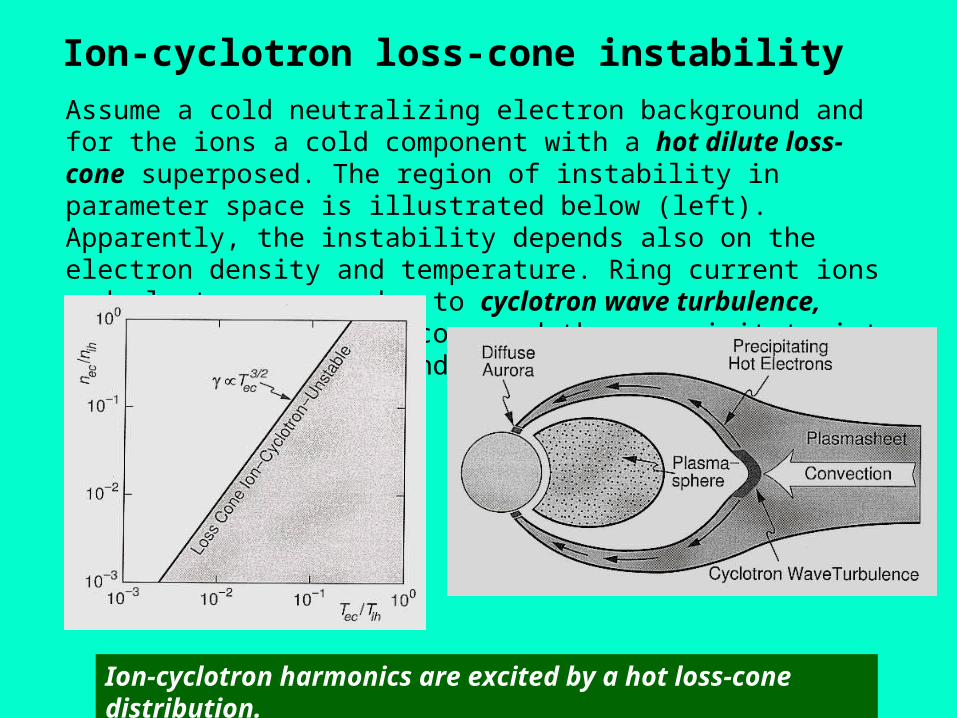
Ion-cyclotron harmonics are excited by a hot loss-cone distribution.
Assume a cold neutralizing electron background and for the ions a cold component with a hot dilute loss-cone superposed. The region of instability in parameter space is illustrated below (left). Apparently, the instability depends also on the electron density and temperature. Ring current ions and electrons can, due to cyclotron wave turbulence, scatter into the loss cone and thus precipitate into the polar ionosphere and create aurora (right figure).
Plasma wave electric field spectra
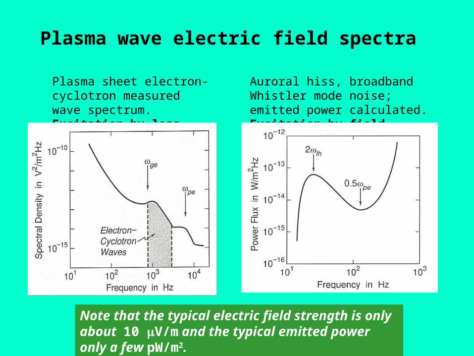
Plasma sheet electron-cyclotron measured wave spectrum. Excitation by loss-cone
Auroral hiss, broadband Whistler mode noise; emitted power calculated. Excitation by field-aligned beam
Note that the typical electric field strength is only about 10 V/m and the typical emitted power only a few pW/m2.
Cyclotron resonance mechanism
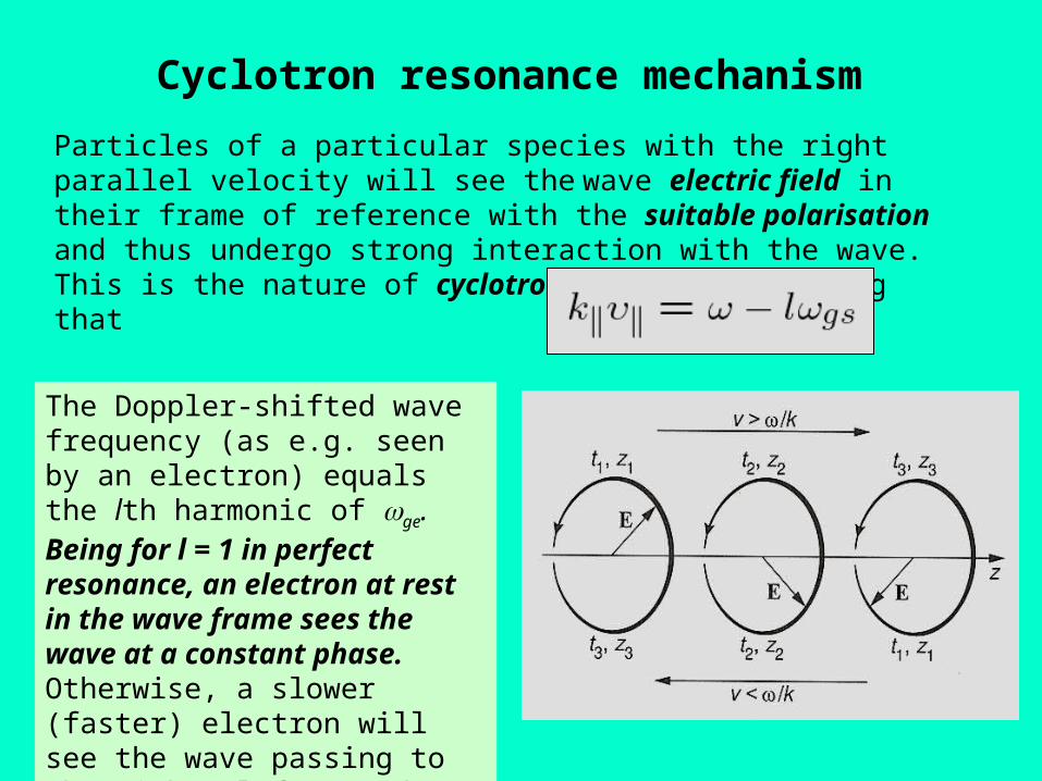
The Doppler-shifted wave frequency (as e.g. seen by an electron) equals the lth harmonic of ge. Being for l = 1 in perfect resonance, an electron at rest in the wave frame sees the wave at a constant phase. Otherwise, a slower (faster) electron will see the wave passing to the right (left), and thus it sees an (L) R-wave (not) polarised in the sense of its gyration.
Particles of a particular species with the right parallel velocity will see the wave electric field in their frame of reference with the suitable polarisation and thus undergo strong interaction with the wave. This is the nature of cyclotron resonance, implying that
Whistler instability I
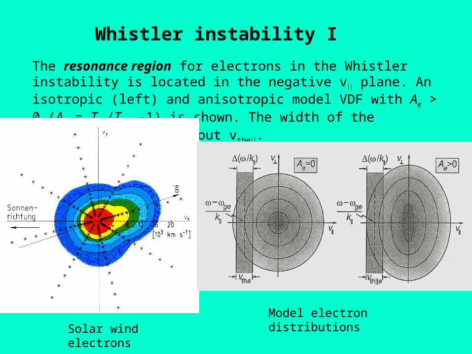
The resonance region for electrons in the Whistler instability is located in the negative v plane. An isotropic (left) and anisotropic model VDF with Ae > 0 (Ae = Te/Te -1) is shown. The width of the resonant region is about vthe.
Solar wind electronsModel electron distributions
Whistler instability II
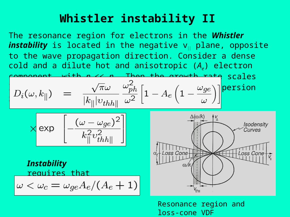
The resonance region for electrons in the Whistler instability is located in the negative v plane, opposite to the wave propagation direction. Consider a dense cold and a dilute hot and anisotropic (Ae) electron component, with nh << nc. Then the growth rate scales like, nh/nc. The imaginary part of the dispersion reads:
Resonance region and loss-cone VDF
Instability requires that
Resonant ion beam instability
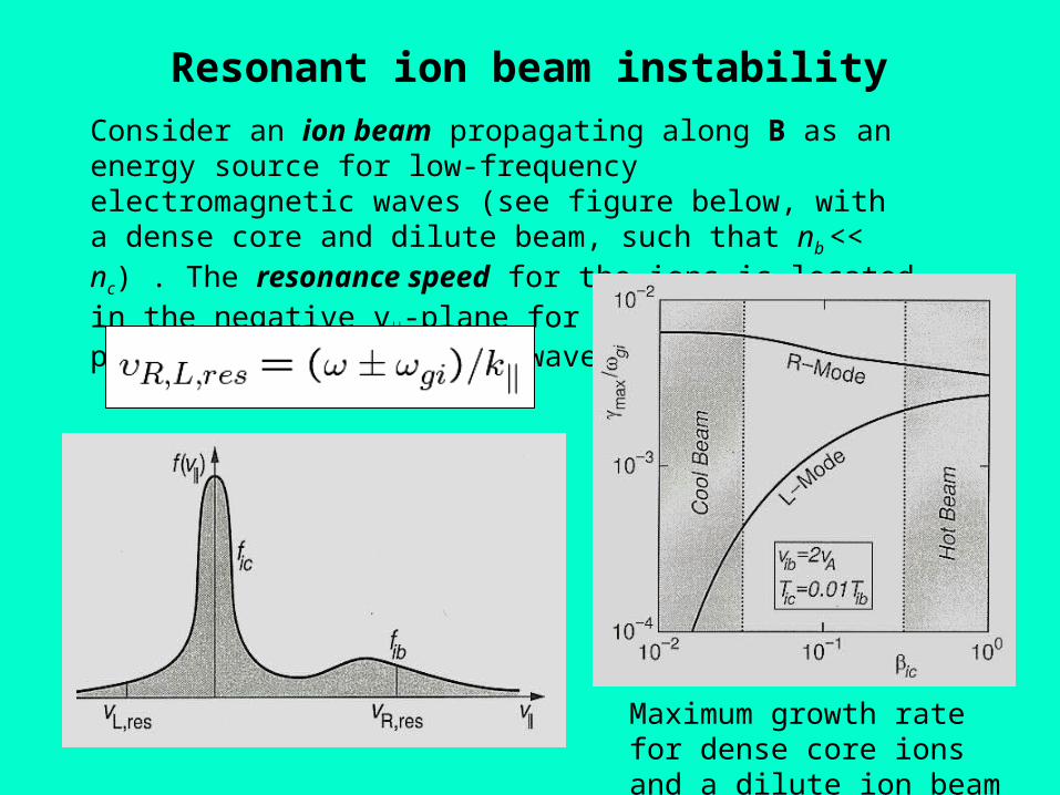
Consider an ion beam propagating along B as an energy source for low-frequency electromagnetic waves (see figure below, with a dense core and dilute beam, such that nb << nc) . The resonance speed for the ions is located in the negative v-plane for L-waves and positive v-plane for R-waves and given by:
Maximum growth rate for dense core ions and a dilute ion beam
Solar wind proton beam and temperature anisotropy
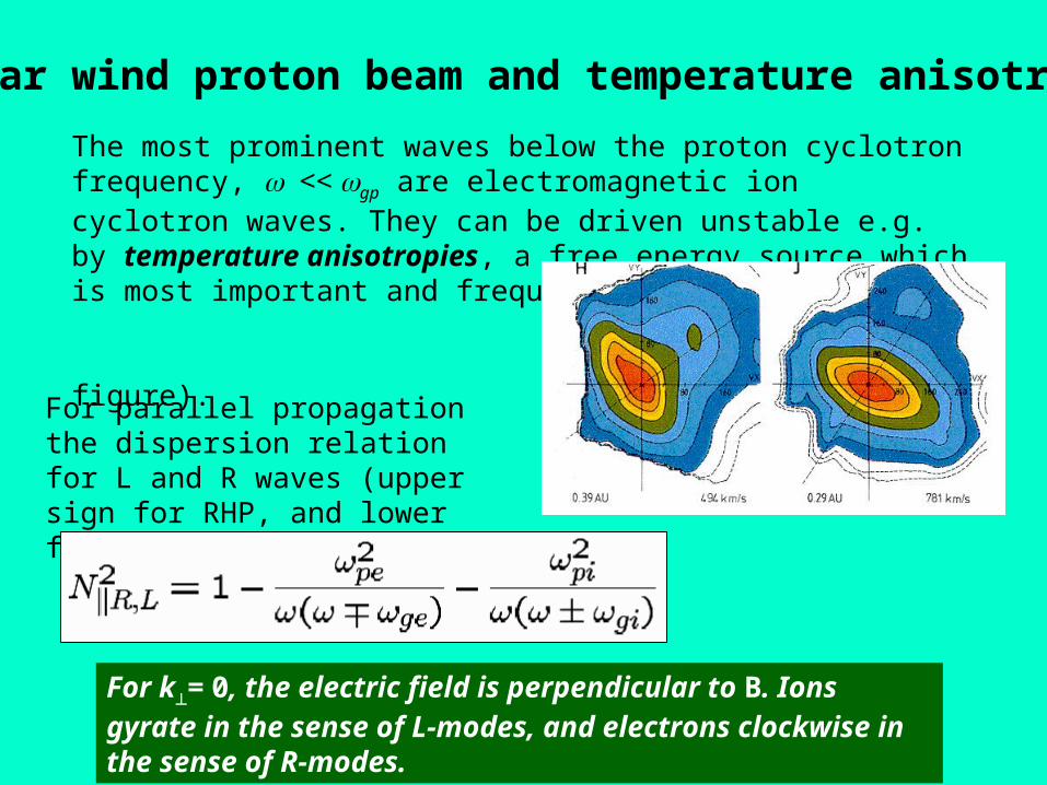
The most prominent waves below the proton cyclotron frequency, << gp are electromagnetic ion cyclotron waves. They can be driven unstable e.g. by temperature anisotropies, a free energy source which is most important and frequent in the solar wind (see the right figure).
For parallel propagation the dispersion relation for L and R waves (upper sign for RHP, and lower for LHP) reads:
For k= 0, the electric field is perpendicular to B. Ions gyrate in the sense of L-modes, and electrons clockwise in the sense of R-modes.
R-wave regulation of solar wind proton beam
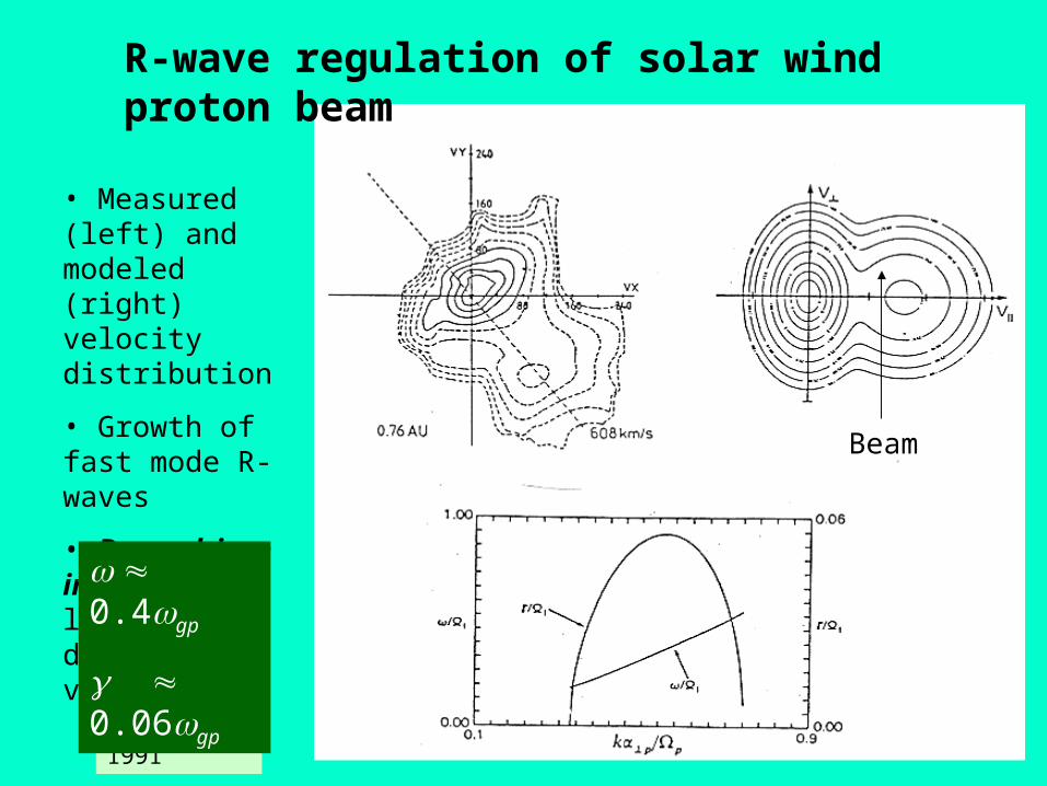
Marsch, 1991
• Measured (left) and modeled (right) velocity distribution
• Growth of fast mode R-waves
• Beam-driven instability, large beam drift speed, vb
0.4gp
0.06gp
Beam
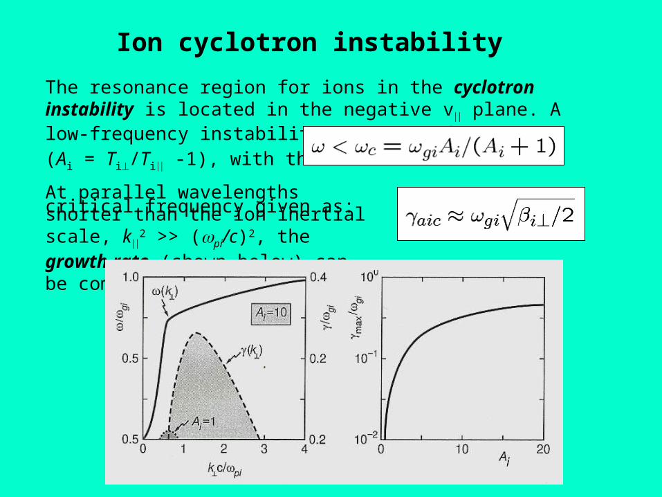
Ion cyclotron instability
The resonance region for ions in the cyclotron instability is located in the negative v plane. A low-frequency instability can occur for Ai > 0 (Ai = Ti/Ti -1), with the critical frequency given as:
At parallel wavelengths shorter than the ion inertial scale, k
2 >> (pi/c)2, the growth rate (shown below) can be comparatively large:
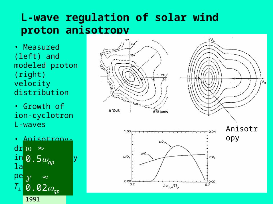
L-wave regulation of solar wind proton anisotropy
• Measured (left) and modeled proton (right) velocity distribution
• Growth of ion-cyclotron L-waves
• Anisotropy-driven instability by large
perpendicular T
Marsch, 1991
0.5gp
0.02gp
Anisotropy
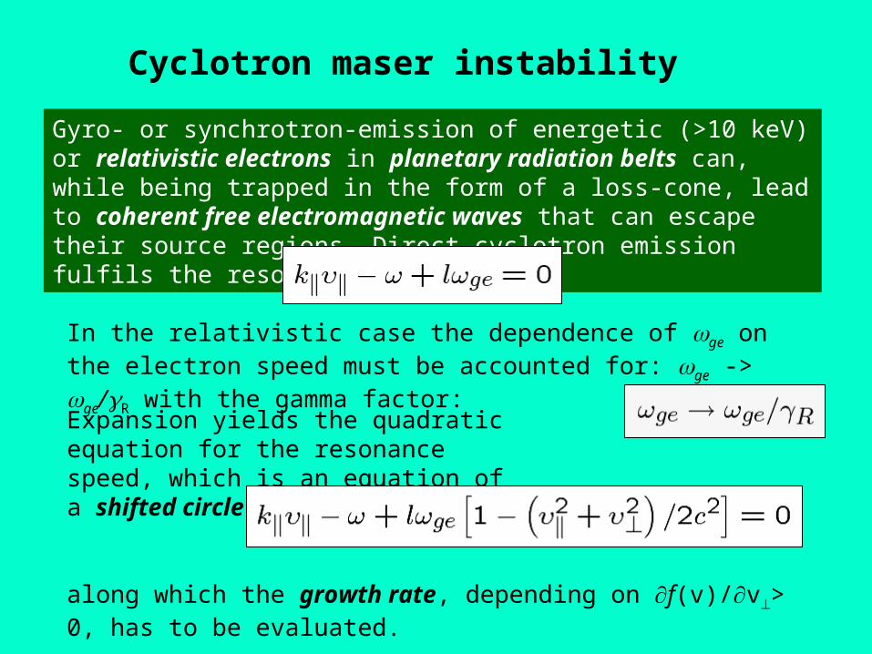
Cyclotron maser instability
Gyro- or synchrotron-emission of energetic (>10 keV) or relativistic electrons in planetary radiation belts can, while being trapped in the form of a loss-cone, lead to coherent free electromagnetic waves that can escape their source regions. Direct cyclotron emission fulfils the resonance condition:
In the relativistic case the dependence of ge on the electron speed must be accounted for: ge -> ge/R with the gamma factor:
Expansion yields the quadratic equation for the resonance speed, which is an equation of a shifted circle,
along which the growth rate, depending on f(v)/v> 0, has to be evaluated.