Franz Reuleaux and the History of Kinematics and Theory of Machines

vtuso
lution
.inKINEMATICS OF MACHINES (10ME44)
QUESTION BANK
1. Define link, Inversion, Kinematic pair, Kinematic chain, Machine
2. List inversions of a four bar chain and explain whit worth quick return motion
mechanism
3. Explain Pantograph
4. Explain Ackerman steering gear mechanism with a neat sketch
5. Explain ratchet and pawl mechanism
6. Explain drag link mechanism
7. Determine the degrees of freedom for the following links
8. With a neat sketch derive the Length of arc of contact Derivation
9. Two gears in mesh have a module of 8mm and a pressure angle of 200. The larger
gear has 57 teeth while the pinion has 23 teeth. If the addendum on pinion and gear
wheel are equal to one module, find
a) The number of pairs of teeth in contact
b) The angle of action of the pinion and the gear wheel
10. With a neat sketch list the classification of followers
11. Two gear wheel mesh externally and are to give a velocity ratio of 3. The teeth are of
in volute form of module 6mm and standard addendum one module. Pressure
angle=180. Pinion rotates at 90 rpm. Find
a) Number of teeth on each wheel so that interference is just avoided
b) Length of path of contact
c) Length of arc of contact
d) Maximum velocity of sliding between teeth
12. Explain law of Gearing with a neat sketch
13. Define Train value and velocity ratio and explain different methods to find velocity
ratio or train value?
14. In an epicyclic gear train as shown in the fig 1. the arm A is fixed to the shaft ‘S’.
The wheel ‘B’ having 100 teeth rotates freely on this shaft ‘S’ wheel ‘F’ 150 teeth
Vtusolution.in
Vtusolution.in

vtuso
lution
.inseparately driven. If the arm A runs at 200 rpm, wheel F at 100 rpm in the same
direction find (1) No of teeth of gear C (2)Speed of wheel ‘B’
15. The gear train shown in the fig 2 Gear A Meshes with gear B. In the compound gear
B-C, Gear C meshes with gear D, rotating relative to A around the same axis of A. If
the gear A is fixed arm F is used as the driving member, determine the speed ratio
ND/NF. Number of teeth on wheels A,B, C and D are 61,61,62,60 respectively.
16. List different types of quick return motion mechanisms and explain Drag link
mechanism?
17. Sketch Peaucellier mechanism and Roberts mechanism?
18. Explain Geneva mechanism with a neat sketch?
19. Explain condition for correct steering in Motor car?
20. An epicyclic gear train is shown in fig 3. The wheel A is fixed and the input at the
arm R is 3kw at 600 rpm. Find the speed of wheel D and the torque on it and the
torque required to hold the wheel ‘A’ neglect frictional losses.
21. Explain torque in an epicyclic gear train?
22. The fig 4 shows an epicyclic gear train. Wheel E is fixed and wheels C and D are
integrally cast and mount on the same pin. If arm A makes one revolution per sec
counterclockwise determine the speed and direction of rotation of the wheels B and F
23. A cam rotating clockwise at uniform speed of 300 rpm operates a reciprocating
follower through a roller 1.5cm diameter. The follower motion is defined as below
a. Outward during 1500 with UARM
b. Dwell for next 300
c. Return during next 1200 with SHM
d. Dwell for the remaining period
Stroke of the follower is 3cm.minimum radius of the cam is 3cm.Draw the cam
profile the follower axis passes through the cam
24. Define Gear train and explain different types of gear train
25. In an epicyclic gear train, the internal wheels A, B and the compound wheel C and D
rotate independently about the axis ‘O’. The wheels E and F rotate on a pin fixed to
the arm G. E gears with A and C, and F gears with B and D. All the wheels have
Vtusolution.in
Vtusolution.in

vtuso
lution
.insame pitch and the number of teeth on E and F are 18,c=28,D=26 1. Sketch the
arrangement 2. Find the number of teeth on A and B 3. If the arm G makes 150 rpm
CW and A is fixed, find speed of B 4. If the arm G makes 150 rpm CW and wheel A
makes 15 rpm CCW, find the speed of B.
26. An eplicyclic gear train is shown in fig the number of teeth on wheel A,B and C are
48,24 and 50 respectively. If the arm rotates 400rpm clockwise find
a. Speed of wheel C when A is fixed
b. Speed of wheel A when C is fixed
Vtusolution.in
Vtusolution.in

vtuso
lution
.inCHAPTER – 1
Quick return motion mechanisms.
Quick return mechanisms are used in machine tools such as shapers and power driven saws
for the purpose of giving the reciprocating cutting tool a slow cutting stroke and a quick
return stroke with a constant angular velocity of the driving crank. Some of the common
types of quick return motion mechanisms are discussed below. The ratio of time required for
the cutting stroke to the time required for the return stroke is called the time ratio and is
greater than unity.
Drag link mechanism
This is one of the inversions of four bar mechanism, with four turning pairs. Here, link 2 is
the input link, moving with constant angular velocity in anti-clockwise direction. Point C of
the mechanism is connected to the tool post E of the machine. During cutting stroke,tool post
moves from E1 to E2. The corresponding positions of C are C1 and C2 as shown in the fig.
For the point C to move from C1 to C2, point B moves from B1 to B2, in anti-clockwise
direction. IE, cutting stroke takes place when input link moves through angle B1AB2 in anti-
clockwise direction and return stroke takes place when input link
The time ratio is given by the following equation.
Whitworth quick return motion mechanism:
This is first inversion of slider mechanism, where, crank 1 is fixed. Input is given to link
2, which moves at constant speed. Point C of the mechanism is connected to the tool post
Vtusolution.in
Vtusolution.in

vtuso
lution
.inD of the machine. During cutting stroke, tool post moves from D1 to D11. The
corresponding positions of C are C1 and C11 as shown in the fig. 1.38. For the point C to
move from C1 to C11, point B moves from B1 to B11, in anti-clockwise direction. I.E.,
cutting stroke takes place when input link moves through angle B1O2B11 in anticlockwise
direction and return stroke takes place when input link moves through angle B11O2B1 in
anti-clockwise direction.
Crank and slotted lever quick return motion mechanism
This is second inversion of slider mechanism, where, connecting rod is fixed. Input is given
to link 2, which moves at constant speed. Point C of the mechanism is connected to
the tool post D of the machine. During cutting stroke, tool post moves from D1 to D11.The
corresponding positions of C are C1 and C11 as shown in the fig. 1.39. For the point C to
move from C1 to C11, point B moves from B1 to B11, in anti-clockwise direction. I.E.,
cutting stroke takes place when input link moves through angle B1O2B11 in anticlockwise
direction and return stroke takes place when input link moves through angle B11O2B1 in
anti-clockwise direction.
Vtusolution.in
Vtusolution.in

vtuso
lution
.in
Straight line motion mechanisms
Straight line motion mechanisms are mechanisms, having a point that moves along a
straight line, or nearly along a straight line, without being guided by a plane surface.
Condition for exact straight line motion:
If point B (fig.1.40) moves on the circumference of a circle with center O and radius OA,
then, point C, which is an extension of AB traces a straight line perpendicular to AO,
provided product of AB and AC is constant.
Vtusolution.in
Vtusolution.in

vtuso
lution
.in
Locus of pt.C will be a straight line, ┴ to AE if, is constant
Proof:
Peaucellier exact straight line motion mechanism:
Fig. Here, AE is the input link and point E moves along a circular path of radius AE = AB.
Also, EC = ED = PC = PD and BC = BD. Point P of the mechanism moves along exact
straight line, perpendicular to BA extended.
To prove B, E and P lie on same straight line:
Triangles BCD, ECD and PCD are all isosceles triangles having common base CD and
apex points being B, E and P. Therefore points B, E and P always lie on the perpendicular
bisector of CD. Hence these three points always lie on the same straight line.
To prove product of BE and BP is constant.
In triangles BFC and PFC,
BC2 FB2 FC2 and PC2 PF 2 FC2
BC2 PC2 FB2 PF 2 FB PFFB PFBP BE
But since BC and PC are constants, product of BP and BE is constant, which is the
condition for exact straight line motion. Thus point P always moves along a straight line
perpendicular to BA as shown in the fig.1.41.
Vtusolution.in
Vtusolution.in
vtuso
lution
.in
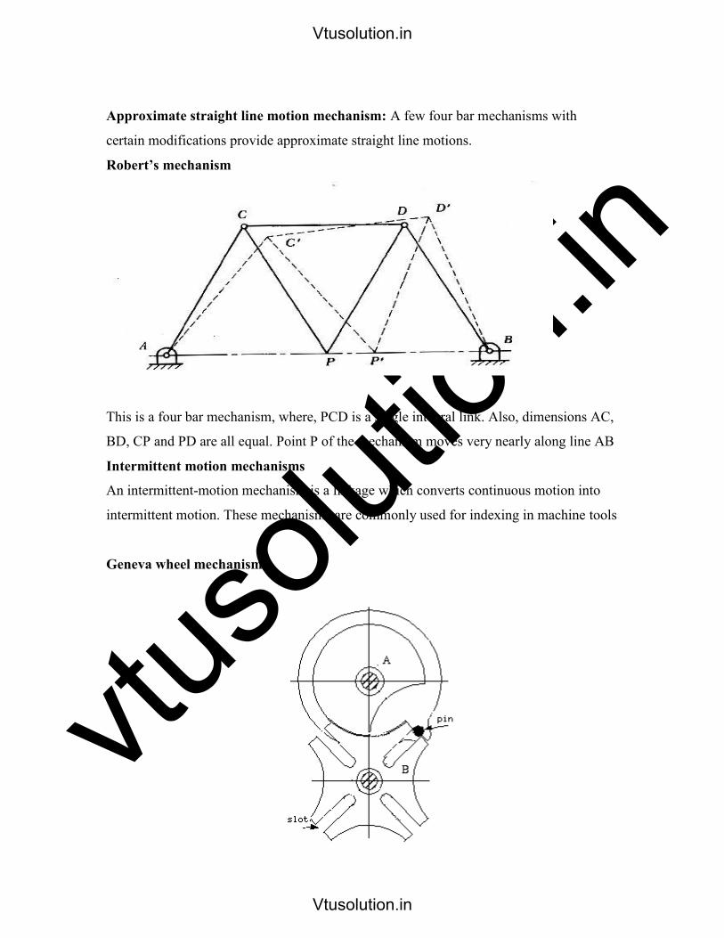
Approximate straight line motion mechanism: A few four bar mechanisms with
certain modifications provide approximate straight line motions.
Robert’s mechanism
This is a four bar mechanism, where, PCD is a single integral link. Also, dimensions AC,
BD, CP and PD are all equal. Point P of the mechanism moves very nearly along line AB
Intermittent motion mechanisms
An intermittent-motion mechanism is a linkage which converts continuous motion into
intermittent motion. These mechanisms are commonly used for indexing in machine tools
Geneva wheel mechanism
Vtusolution.in
Vtusolution.in

vtuso
lution
.in
In the mechanism shown (Fig.1.43), link A is driver and it contains a pin which engages
with the slots in the driven link B. The slots are positioned in such a manner, that the pin
enters and leaves them tangentially avoiding impact loading during transmission of
motion. In the mechanism shown, the driven member makes one-fourth of a revolution
for each revolution of the driver. The locking plate, which is mounted on the driver,
prevents the driven member from rotating except during the indexing period.
Ratchet and pawl mechanism
Ratchets are used to transform motion of rotation or translation into intermittent rotation
or translation. In the fig.1.44, A is the ratchet wheel and C is the pawl. As lever B is made
to oscillate, the ratchet wheel will rotate anticlockwise with an intermittent motion. A
holding pawl D is provided to prevent the reverse motion of ratchet wheel.
Other mechanisms
Toggle mechanism
Vtusolution.in
Vtusolution.in

vtuso
lution
.in
Toggle mechanisms are used, where large resistances are to be overcome through short
distances. Here, effort applied will be small but acts over large distance. In the mechanism
shown in fig.1.45, 2 is the input link, to which, power is supplied and 6 is the
output link, which has to overcome external resistance. Links 4 and 5 are of equal length.
Considering the equilibrium condition of slider 6,
For small angles of α, F (effort) is much smaller than P(resistance).
This mechanism is used in rock crushers, presses, riveting machines etc.
Pantograph
Pantographs are used for reducing or enlarging drawings and maps. They are also used
for guiding cutting tools or torches to fabricate complicated shapes.
In the mechanism shown in fig.1.46 path traced by point A will be magnified by point E
to scale, as discussed below.
In the mechanism shown, AB = CD; AD =BC and OAE lie on a straight line.
When point A moves to A, E moves to Eand OAEalso lies on a straight line.
From the fig.1.46, ODA OCE and ODAOCE.
Hooke’s joint (Universal joints)
Hooke’s joins is used to connect two nonparallel but intersecting shafts. In its basic
Vtusolution.in
Vtusolution.in

vtuso
lution
.inshape, it has two U –shaped yokes ‘a’ and ‘b’ and a center block or cross-shaped piece,
C. fig The universal joint can transmit power between two shafts intersecting at around 300
angles (α). However, the angular velocity ratio is not uniform during the cycle of operation.
The amount of fluctuation depends on the angle (α) between the two shafts.
For uniform transmission of motion, a pair of universal joints should be used fig.
Intermediate shaft 3 connects input shaft 1 and output shaft 2 with two
universal joints. The angle α between 1 and 2 is equal to angle α between 2 and 3. When
shaft 1 has uniform rotation, shaft 3 varies in speed; however, this variation is compensated
by the universal joint between shafts 2 and 3. One of the important
applications of universal joint is in automobiles, where it is used to transmit power from
engine to the wheel axle.
Steering gear mechanism
The steering mechanism is used in automobiles for changing the directions of the wheel
axles with reference to the chassis, so as to move the automobile in the desired path.
Usually, the two back wheels will have a common axis, which is fixed in direction with
reference to the chassis and the steering is done by means of front wheels.
Vtusolution.in
Vtusolution.in
vtuso
lution
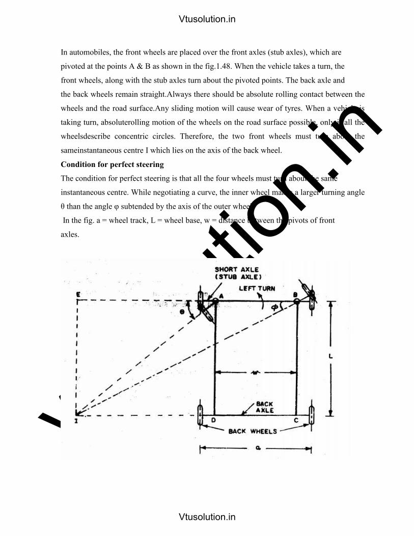
.inIn automobiles, the front wheels are placed over the front axles (stub axles), which are
pivoted at the points A & B as shown in the fig.1.48. When the vehicle takes a turn, the
front wheels, along with the stub axles turn about the pivoted points. The back axle and
the back wheels remain straight.Always there should be absolute rolling contact between the
wheels and the road surface.Any sliding motion will cause wear of tyres. When a vehicle is
taking turn, absoluterolling motion of the wheels on the road surface possible, only if all the
wheelsdescribe concentric circles. Therefore, the two front wheels must turn about the
sameinstantaneous centre I which lies on the axis of the back wheel.
Condition for perfect steering
The condition for perfect steering is that all the four wheels must turn about the same
instantaneous centre. While negotiating a curve, the inner wheel makes a larger turning angle
θ than the angle φ subtended by the axis of the outer wheel.
In the fig. a = wheel track, L = wheel base, w = distance between the pivots of front
axles.
Vtusolution.in
Vtusolution.in

vtuso
lution
.inThis is the fundamental equation for correct steering. If this condition is satisfied, there will
be no skidding of the wheels when the vehicle takes a turn.
Ackermann steering gear mechanism
Ackerman steering mechanism, RSAB is a four bar chain as shown in fig.1.50. Links RA
and SB which are equal in length are integral with the stub axles. These links are
connected with each other through track rod AB. When the vehicle is in straight ahead
position, links RA and SB make equal angles α with the center line of the vehicle. The
dotted lines in fig.1.50 indicate the position of the mechanism when the vehicle is turning
left. Angle α can be determined using the above equation. The values of θ and φ to be taken
in this equation are those found for correct steering using the equation L
This mechanism gives correct steering in only three positions. One, when θ = 0 and other
two each corresponding to the turn to right or left (at a fixed turning angle, as determined
by equation .The correct values of φ, [φc] corresponding to different values of θ, for correct
steering can be determined using equation [2]. For the given dimensions of the mechanism,
Vtusolution.in
Vtusolution.in
vtuso
lution
.inactual values of φ, [φa] can be obtained for different values of θ. T he difference between φc
and φa will be very small for small angles of θ, but the difference will be substantial, for
larger values of θ. Such a difference will reduce the life of tyres because of greater wear on
account of slipping.
But for larger values of θ, the automobile must take a sharp turn; hence is will be moving
at a slow speed. At low speeds, wear of the tyres is less. Therefore, the greater difference
between φc and φa larger values of θ ill not matter.
As this mechanism employs only turning pairs, friction and wear in the mechanism will
be less. Hence its maintenance will be easier and is commonly employed in automobiles.
Vtusolution.in
Vtusolution.in
vtuso
lution
.inCHAPTER 2 and 3
VELOCITY AND ACCELERATION
• Introduction
Kinematics deals with study of relative motion between the various parts of the machines.
Kinematics does not involve study of forces. Thus motion leads study of displacement,
velocity and acceleration of a part of the machine. Study of Motions of various parts of a
machine is important for determining their velocities and accelerations at different moments.
As dynamic forces are a function of acceleration and acceleration is a function of velocities,
study of velocity and acceleration will be useful in the design of mechanism of a machine.
The mechanism will be represented by a line diagram which is known as configuration
diagram. The analysis can be carried out both by graphical method as well as analytical
method.
• Some important Definitions
Displacement: All particles of a body move in parallel planes and travel by same distance is
known, linear displacement and is denoted by ‘x’.
A body rotating about a fired point in such a way that all particular move in circular path
angular displacement
Velocity: Rate of change of displacement is velocity. Velocity can be linear velocity of
angular velocity. Relation between linear velocity and angular velocity.
Some important Definitions
Displacement: All particles of a body move in parallel planes and travel by same distance is
known, linear displacement and is denoted by ‘x’.
A body rotating about a fired point in such a way that all particular move in circular path
angular displacement and is denoted by ‘ ’.
Velocity: Rate of change of displacement is velocity. Velocity can be linear velocity of
angular velocity.Linear velocity is Rate of change of linear displacement,Angular velocity is
Rate of change of angular displacement ,Relation between linear velocity and angular
velocity.
Acceleration: Rate of change of velocity
Absolute velocity: Velocity of a point with respect to a fixed point (zero velocity point).A
Vtusolution.in
Vtusolution.in

vtuso
lution
.in2
Va = 2 x r
Va = 2 x O2 A
Ex: Vao2 is absolute velocity.
Relative velocity: Velocity of a point with respect to another point ‘x’
B
Ex: Vba Velocity of point B with respect to A
Note: Capital letters are used for configuration diagram. Small letters are used for velocity
vector diagram.
This is absolute velocity
Velocity of point A with respect to O2 fixed point, zero velocity point.
B
A
Vba = or Vab
Vba = or Vab Equal in magnitude but opposite in direction.
B
O4
Vb Absolute velocity is velocity of B with respect to O4 (fixed point, zero
velocity point)
3
O 2 O 4
2
A 3
4
O 2
Vtusolution.in
Vtusolution.in

vtuso
lution
.in
Velocity vector diagram
Vector O2a = Va= Absolute velocity
Vector ab = Vab
Relative velocity
ba = Va
Vab is equal magnitude with Vba but is apposite in direction.
Vector O4 b = Vb absolute velocity.
To illustrate the difference between absolute velocity and relative velocity. Let, us consider a
simple situation.
A link AB moving in a vertical plane such that the link is inclined at 30o to the horizontal
with point A is moving horizontally at 4 m/s and point B moving vertically upwards. Find
velocity of B.
Va = 4 m/s ab Absolute velocity Horizontal direction
Vb = ? ab Absolute velocity Vertical direction
b V ba
V ab
V b
O 2 , O 4
a
Vtusolution.in
Vtusolution.in

vtuso
lution
.in Velocity of B with respect to A is equal in magnitude to velocity of A with respect to B but
opposite in direction. Relative Velocity Equation
Fig. 1 Point O is fixed and End A is a point on rigid body.Relative Velocity Equation of
Two Points on a Rigid link
1. By graphical method
2. By relative velocity method
3. By instantaneous method
x A
R sin
A
y B
x
Rigid body
y A
B
R cos
x B
O 4
y a
y
R
A
x A x
Rigid body
O
known in directors only ( )
C
O
V b
V ba
a V a
V ab 30
o
B
4 m/s A
Vtusolution.in
Vtusolution.in

vtuso
lution
.in By Graphical Method
The following points are to be considered while solving problems by this method.
1. Draw the configuration design to a suitable scale.
2. Locate all fixed point in a mechanism as a common point in velocity diagram.
3. Choose a suitable scale for the vector diagram velocity.
4. The velocity vector of each rotating link is r to the link.
5. Velocity of each link in mechanism has both magnitude and direction. Start from a
point whose magnitude and direction is known.
6. The points of the velocity diagram are indicated by small letters.
To explain the method let us take a few specific examples.
1. Four – Bar Mechanism: In a four bar chain ABCD link AD is fixed and in 15 cm long.
The crank AB is 4 cm long rotates at 180 rpm (cw) while link CD rotates about D is 8 cm
long BC = AD and | BAD = 60o. Find angular velocity of link
CD.
C
Configuration Diagram
Velocity vector diagram
Vb = r = ba x AB = x4 = 50.24 cm/sec
60 o
ω BA
A D
B
15 cm
15 cm
8 cm
Vtusolution.in
Vtusolution.in

vtuso
lution
.in
Choose a suitable scale
1 cm = 20 m/s = ab
Vcb = bc
Vc = dc = 38 cm/sec = Vcd
We know that V =ω R
Vcd = CD x CD
ωcD = Vcd 38 4.75rad/sec (cw)
CD 8
2. Slider Crank Mechanism:
In a crank and slotted lever mechanism crank rotates of 300 rpm in a counter
clockwise direction. Find
(i) Angular velocity of connecting rod and (ii) Velocity
of slider.
Configuration diagram
Step 1: Determine the magnitude and velocity of point A with respect to 0,
VA = O1A x O2A = x60
= 600 mm/sec
60 mm
45 o
A
B
150 mm
r to CD
r to BC
r to AB
a, d
b
c V cb
Vtusolution.in
Vtusolution.in

vtuso
lution
.inStep 2: Choose a suitable scale to draw velocity vector diagram.
3. Shaper Mechanism:
In a crank and slotted lever mechanisms crank O2A rotates at rad/sec in CCW
direction. Determine the velocity of slider.
6
Configuration diagram
Scale 1 cm = ……x…. m/s a
Velocity vector diagram d O 1 O 2
V DC
c b
V BA V AO2 = V A
V BO1
4
O 1
O 2
C
B
3
2
ω
5 D
Scale 1 cm = ……x…. m
Velocity vector diagram
O
V a a
b
r to AB r to OA
Along sides B
Vtusolution.in
Vtusolution.in

vtuso
lution
.inTo Determine Velocity of Rubbing
Two links of a mechanism having turning point will be connected by pins. When the
links are motion they rub against pin surface. The velocity of rubbing of pins depends on the
angular velocity of links relative to each other as well as direction.
For example: In a four bar mechanism we have pins at points A, B, C and D.
Problem 1:
In a four bar mechanism, the dimensions of the links are as given below:
AB = 50 mm, BC = 66 mm
CD = 56 mm and AD = 100 mm
At a given instant when |DAB 60o the angular velocity of link AB is 10.5
rad/sec in CCW direction.
Determine,
i) Velocity of point C
ii) Velocity of point E on link BC when BE = 40 mm iii) The
angular velocity of link BC and CD
iv) The velocity of an offset point F on link BC, if BF = 45 mm, CF = 30 mm and
BCF is read clockwise.
v) The velocity of an offset point G on link CD, if CG = 24 mm, DG = 44 mm
and DCG is read clockwise.
vi) The velocity of rubbing of pins A, B, C and D. The ratio of the pins are 30
mm, 40 mm, 25 mm and 35 mm respectively.
Solution:
Step -1: Construct the configuration diagram selecting a suitable scale.
Scale: 1 cm = 20 mm
Vtusolution.in
Vtusolution.in

vtuso
lution
.in Step – 2: Given the angular velocity of link AB and its direction of rotation determine
velocity of point with respect to A (A is fixed hence, it is zero velocity point).
Vba = BA x BA
= 10.5 x 0.05 = 0.525 m/s
Step – 3: To draw velocity vector diagram choose a suitable scale, say 1 cm = 0.2 m/s.
First locate zero velocity points.
• Draw a line r to link AB in the direction of rotation of link AB (CCW) equal to
0.525 m/s.
b
• From b draw a line r to BC and from d. Draw d line r to CD to interest at C.
• Vcb is given vector bc Vbc = 0.44 m/s
• Vcd is given vector dc Vcd = 0.39 m/s
Step – 4: To determine velocity of point E (Absolute velocity) on link BC, first locate the
position of point E on velocity vector diagram. This can be done by taking corresponding
ratios of lengths of links to vector distance i.e.
be BE
bc BC
be = BE x Vcb = 0.04 x 0.44 = 0.24 m/s
C
f
V ed
a, d
e, g
V ba = 0.525 m/s
60 o
A D
B
C
F
G
Vtusolution.in
Vtusolution.in

vtuso
lution
.in BC 0.066
Join e on velocity vector diagram to zero velocity points a, d / vector de = Ve = 0.415
m/s.
Step 5: To determine angular velocity of links BC and CD, we know Vbc and Vcd.
Vbc =ω BC x BC
ωBC = Vbc 0.44 6.6 r / s . (cw) BC 0.066
Similarly, Vcd = ωCD x CD
ωCD = Vcd 0.39 6.96 r /s (CCW) CD 0.056
Step – 6: To determine velocity of an offset point F
• Draw a line r to CF from C on velocity vector diagram.
• Draw a line r to BF from b on velocity vector diagram to intersect the previously
drawn line at ‘f’.
• From the point f to zero velocity point a, d and measure vector fa to get Vf = 0.495
m/s.
Step – 7: To determine velocity of an offset point.
• Draw a line r to GC from C on velocity vector diagram.
• Draw a line r to DG from d on velocity vector diagram to intersect previously drawn
line at g.
• Measure vector dg to get velocity of point G.
Vg = dg 0.305 m/s
Step – 8: To determine rubbing velocity at pins
• Rubbing velocity at pin A will be
Vpa = ab x r of pin A Vpa = 10.5 x 0.03
= 0.315 m/s
• Rubbing velocity at pin B will be
Vpb = ( ab + cb) x rpb of point at B.
[ ab CCW and cbCW]
Vpb = (10.5 + 6.6) x 0.04 = 0.684 m/s.
Rubbing velocity at point C will be
Vtusolution.in
Vtusolution.in

vtuso
lution
.in= 6.96 x 0.035 = 0.244 m/s
Problem 2:
In a slider crank mechanism the crank is 200 mm long and rotates at 40 rad/sec in a
CCW direction. The length of the connecting rod is 800 mm. When the crank turns through
60o from Inner-dead centre.
Determine,
i) The velocity of the slider
ii) Velocity of point E located at a distance of 200 mm on the connecting rod extended.
iii) The position and velocity of point F on the connecting rod having the least
absolute velocity.
iv) The angular velocity of connecting rod.
v) The velocity of rubbing of pins of crank shaft, crank and cross head having pins
diameters 80,60 and 100 mm respectively.
Solution:
Step 1: Draw the configuration diagram by selecting a suitable scale.
E
Va = Woa x OA
Va = 40 x 0.2
Va = 8 m/s
Step 2: Choose a suitable scale for velocity vector diagram and draw the velocity vector
diagram.
• Mark zero velocity point o, g.
• Draw oa r to link OA equal to 8 m/s
45 o
B
F
A
O G
Vtusolution.in
Vtusolution.in

vtuso
lution
.in Scale: 1 cm = 2 m/s
• From a draw a line r to AB and from o, g draw a horizontal line (representing the
line of motion of slider B) to intersect the previously drawn line at b.
• ab give Vba=4.8 m/sec
Step – 3: To mark point ‘e’ since ‘E’ is on the extension of link AB drawn be =
BE AB
x ab mark the point e on extension of vector ba. Join e to o, g. ge will give
velocity of point E.
Ve = ge=8.4 m/sec
Step 4: To mark point F on link AB such that this has least velocity (absolute).
Draw a line r to ab passing through o, g to cut the vector ab at f. From f to
o, g. gf will have the least absolute velocity.
To mark the position of F on link AB.
Find BF by using the relation.
fb ab
BF AB
BF fb x AB=200mm ab
Step – 5: To determine the angular velocity of connecting rod.
We know that Vab = ab x AB
ab = Vab = 6 rad/sec AB
Step – 6: To determine velocity of rubbing of pins.
• Vpcrankshaft = ao x radius of crankshaft pin
e
a
f
b o, g
Vtusolution.in
Vtusolution.in
vtuso
lution
.in= 8 x 0.08
= 0.64 m/s
• VPcrank pin = ( ab + oa) rcrank pin= (6 +8)0.06 =0.84 m/sec
• VP cross head = ab x rcross head = 6 x 0.1 = 0.6 m/sec
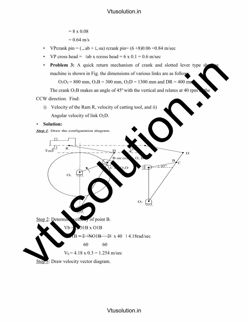
• Problem 3: A quick return mechanism of crank and slotted lever type shaping
machine is shown in Fig. the dimensions of various links are as follows.
O1O2 = 800 mm, O1B = 300 mm, O2D = 1300 mm and DR = 400 mm
The crank O1B makes an angle of 45o with the vertical and relates at 40 rpm in the
CCW direction. Find:
i) Velocity of the Ram R, velocity of cutting tool, and ii)
Angular velocity of link O2D.
• Solution:
Step 2: Determine velocity of point B.
Vb = O1B x O1B
O1B = 2 NO1B 2 x 40 4.18rad/sec
60 60
Vb = 4.18 x 0.3 = 1.254 m/sec
Step 3: Draw velocity vector diagram.
Vtusolution.in
Vtusolution.in

vtuso
lution
.in
Draw O1b r to link O1B equal to 1.254 m/s. o From b draw a line along the line of O2B
and from O1O2 draw a line r to O2B. This intersects at c bc will measure velocity of
sliding of slider and O2C will measure the velocity of C on link O2C.
Since point D is on the extension of link O2C measure O2d such that
From d draw a line r to link DR and from O1O2. Draw a line along the line of stroke of
Ram R (horizontal), These two lines will intersect at point r O2r will give the velocity of
Ram R.
To determine the angular velocity of link O2D determine Vd =O2d .
• Problem 4: Figure below shows a toggle mechanisms in which the crank OA rotates at
120 rpm. Find the velocity and acceleration of the slider D.
• Solution:
Configuration Diagram
Step 1: Draw the configuration diagram choosing a suitable scal.
Choose a suita ble scale 1 cm = 0.3 m/sec
r O 1 O 2
d
b
c
Vtusolution.in
Vtusolution.in
vtuso
lution
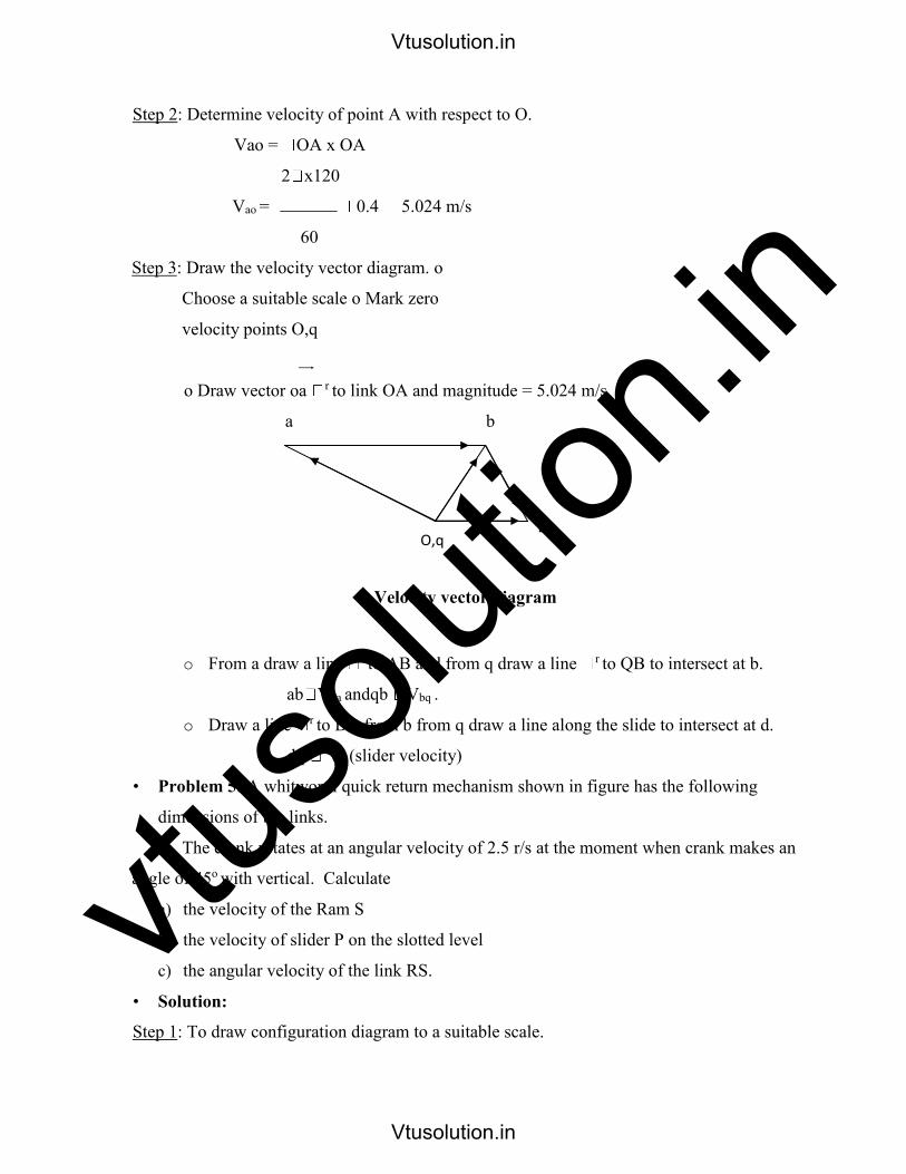
.inStep 2: Determine velocity of point A with respect to O.
Vao = OA x OA
2 x120
Vao = 0.4 5.024 m/s
60
Step 3: Draw the velocity vector diagram. o
Choose a suitable scale o Mark zero
velocity points O,q
o Draw vector oa r to link OA and magnitude = 5.024 m/s.
a b
Velocity vector diagram
o From a draw a line r to AB and from q draw a line r to QB to intersect at b.
ab Vba andqb Vbq .
o Draw a line r to BD from b from q draw a line along the slide to intersect at d.
dq Vd (slider velocity)
• Problem 5: A whitworth quick return mechanism shown in figure has the following
dimensions of the links.
The crank rotates at an angular velocity of 2.5 r/s at the moment when crank makes an
angle of 45o with vertical. Calculate
a) the velocity of the Ram S
b) the velocity of slider P on the slotted level
c) the angular velocity of the link RS.
• Solution:
Step 1: To draw configuration diagram to a suitable scale.
D O,q
Vtusolution.in
Vtusolution.in

vtuso
lution
.in
Configuration Diagram
Step 2: To determine the absolute velocity of point P.
VP = OP x OP
2 x240
Vao = x 0.24 0.6m/s
60
Step 3: Draw the velocity vector diagram by choosing a suitable scale.
P
Velocity vector diagram
o Draw op
r link OP = 0.6 m.
q
r
S
O, a, g
0.6 m
S
R
A
O
B
P on slider Q on BA 45
o
Vtusolution.in
Vtusolution.in

vtuso
lution
.ino From O, a, g draw a line r to AP/AQ and from P draw a line along AP to
intersect previously draw, line at q. Pq = Velocity of sliding.
aq= Velocity of Q with respect to A.
Vqa = aq=
o Angular velocity of link RS = RS sr rad/sec
SR
• Problem 6: A toggle mechanism is shown in figure along with the diagrams of the links
in mm. find the velocities of the points B and C and the angular velocities of links AB,
BQ and BC. The crank rotates at 50 rpm in the clockwise direction.
All dimensions are in mm O
• Solution
Step 1: Draw the configuration diagram to a suitable scale.
Step 2: Calculate the magnitude of velocity of A with respect to O.
Va = OA x OA
Va = 2 x 50 x 0.03 0.05 m/s 0.1507m/s
60
Vtusolution.in
Vtusolution.in

vtuso
lution
.in
Vector velocity diagram
Step 3: Draw the velocity vector diagram by choosing a suitable scale.
o Draw Oa r to link OA = 0.15 m/s
o From a draw a link r to AB and from O, q draw a link r to BQ to intersect at b.
ab Vba and qb Vb 0.13m / s
ab = ab 0.74r / s(ccw) bq
qb 1.3 r / s (ccw)
AB aB
o From b draw a line r to Be and from O, q these two lines intersect at C.
OC VC 0.106m / s bC VCb
BC bc 1.33 r / s (ccw) BC
Problem 7: The mechanism of a stone crusher has the dimensions as shown in figure in
mm. If crank rotates at 120 rpm CW. Find the velocity of point K when crank OA is
inclined at 30o to the horizontal. What will be the torque required at the crank to
overcome a horizontal force of 40 kN at K.
b a
O, q c
Vtusolution.in
Vtusolution.in

vtuso
lution
.in
Configuration diagram
Solution:
Step 1: Draw the configuration diagram to a suitable scale.
Step 2: Given speed of crank OA determine velocity of A with respect to ‘o’.
Va = OA x OA = 2 x 120 x 0.1 1.26 m/s
60
Velocity vector diagram
Step 3: Draw the velocity vector diagram by selecting a suitable scale.
Vtusolution.in
Vtusolution.in

vtuso
lution
.ino Draw Oa r to link OA = 1.26 m/s o From a draw a link r to AB and from q draw a
link r to BQ to intersect at b. o From b draw a line r to BC and from a, draw a line r to AC to intersect at c. o From c draw a line r to CD and from m draw a line r to
MD to intersect at d.
o From d draw a line r to KD and from m draw a line r to KM to x intersect the
previously drawn line at k.
o Since we have to determine the torque required at OA to overcome a horizontal force
of 40 kN at K. Draw a the horizontal line from o, q, m and c line r to this line from
k.
T IP T OP
V = R T = F x P F = T
r
OA TOA = Fk Vk horizontal
TOA = = N-m
Problem 8: In the mechanism shown in figure link OA = 320 mm, AC
= 680 mm and OQ = 650 mm.
Determine,
i) The angular velocity of the cylinder
ii) The sliding velocity of the plunger
iii) The absolute velocity of the plunger
When the crank OA rotates at 20 rad/sec clockwise.
• Solution:
Step 2: Draw the velocity vector diagram o Determine velocity
of point A with respect to O.
TOA
=
Fk
Vk h
z
OA
Step 1 : Draw the configuration diagram.
A
O R
B on AR (point on AR below Q)
60 o C
Vtusolution.in
Vtusolution.in

vtuso
lution
.inVa = OA x OA = 20 x 0.32 = 6.4 m/s
o Select a suitable scale to draw the velocity vector diagram.
o Mark the zero velocity point. Draw vector oa r to link OA equal to 6.4 m/s.
a
b
o From a draw a line r to AB and from o, q, draw a line perpendicular to AB. o To
mark point c on ab
We know that ab AB ac AC
ac ab x AC =
AB
o Mark point c on ab and joint this to zero velocity point. o Angular velocity of
cylinder will be.
ab = Vab = 5.61 rad/sec (c ) AB
o Studying velocity of player will be
qb = 4.1 m/s
OC
o Absolute velocity of plunger == 4.22 m/s qc
• Problem 9: In a swiveling joint mechanism shown in figure link AB is the driving
crank which rotates at 300 rpm clockwise. The length of the various links are:
Determine,
i) The velocity of slider block S ii) The angular velocity of link EF iii) The
velocity of link EF in the swivel block.
• Solution:
O, q c
Vtusolution.in
Vtusolution.in

vtuso
lution
.in
Step 2: Determine the velocity of point B with respect to A.
Vb = BA x BA
Vb = x 0.1 = 3.14 m/s
Step 3: Draw the velocity vector diagram choosing a suitable scale. o Mark
zero velocity point a, d, o, g.
Velocity vector diagram
o From ‘a’ draw a line r to AB and equal to 3.14 m/s.
o From ‘b’ draw a line r to DC to intersect at C.
o Mark a point ‘e’ on vector bc such that be bcx BE
BC
a, d, o, g
c
b
P
f
S
Vtusolution.in
Vtusolution.in

vtuso
lution
.ino From ‘e’ draw a line r to PE and from ‘a,d’ draw a line along PE to intersect
at P.
o Extend the vector ep to ef such that ef ef x EF EP
o From ‘f’ draw a line r to Sf and from zero velocity point draw a line along the slider
‘S’ to intersect the previously drawn line at S.
o Velocity of slider gS 2.6m/s . Angular Velocity of link EF.
o Velocity of link F in the swivel block = OP 1.85 m/s .
• Problem 10: Figure shows two wheels 2 and 4 which rolls on a fixed link 1. The angular
uniform velocity of wheel is 2 is 10 rod/sec. Determine the angular velocity of links 3
and 4, and also the relative velocity of point D with respect to point E.
• Solution:
Step 1: Draw the configuration diagram.
Step 2: Given 2 = 10 rad/sec. Calculate velocity of B with respect to G.
Vb = 2 x BG
Vb = 10 x 43 = 430 mm/sec.
Step 3: Draw the velocity vector diagram by choosing a suitable scale.
B
mm 50
40 mm
30 o 60 mm
3
2
G
2
B
C
D
F
4
A
Vtusolution.in
Vtusolution.in

vtuso
lution
.in Redrawn configuration diagram
• Velocity vector diagram
o Draw gb= 0.43 m/s r to BG.
o From b draw a line r to BC and from ‘f’ draw a line r to CF to intersect at C.
o From b draw a line r to BE and from g, f draw a line r to GE to intersect at e. o
From c draw a line r to CD and from f draw a line r to FD to intersect at d.
• Problem 11: For the mechanism shown in figure link 2 rotates at constant angular
velocity of 1 rad/sec construct the velocity polygon and determine.
i) Velocity of point D.
ii) Angular velocity of link BD. iii)
Velocity of slider C.
• Solution:
e g, f d
b
c
30 o
G
E
F
D
C
50 mm
Vtusolution.in
Vtusolution.in

vtuso
lution
.in4 Step 2:
Determine velocity of A with respect to O2.
Vb = 2 x O2A
Vb = 1 x 50.8 = 50.8 mm/sec.
Step 3: Draw the velocity vector diagram, locate zero velocity points O2O6.
a
o From O2, O6 draw a line r to O2A in the direction of rotation equal to 50.8 mm/sec.
o From a draw a line r to Ac and from O2, O6 draw a line along the line of stocks of c
to intersect the previously drawn line at c.
o Mark point b on vector ac such that ab ab xAB AC
o From b draw a line r to BD and from O2, O6 draw a line r to O6D to intersect at d.
Step 4: Vd = O6d = 32 mm/sec
ADDITIONAL PROBLEMS FOR PRACTICE
O 2 O 6 C
b
V d
d U db
Vtusolution.in
Vtusolution.in

vtuso
lution
.in• Problem 1: In a slider crank mechanism shown in offset by a perpendicular distance of
50 mm from the centre C. AB and BC are 750 mm and 200 mm long respectively crank
BC is rotating e at a uniform speed of 200 rpm. Draw the velocity vector diagram and
determine velocity of slider A and angular velocity of link AB.
• Problem 2: For the mechanism shown in figure determine the velocities at points C, E
and F and the angular velocities of links, BC, CDE and EF.
C All dimensions are in mm
50
• The crank op of a crank and slotted lever mechanism shown in figure rotates at 100 rpm
in the CCW direction. Various lengths of the links are OP = 90 mm, OA = 300 mm, AR
= 480 mm and RS = 330 mm. The slider moves along an axis perpendicular to r AO and
in 120 mm from O. Determine the velocity of the slider when |AOP is 135o and also
mention the maximum velocity of slider.
D
B O
45 o
A
C
F
E B
A
120
D
150 100
100 rpm
60
120 o
120
A
C
50 mm
B
Vtusolution.in
Vtusolution.in

vtuso
lution
.in• Problem 4: Find the velocity of link 4 of the scotch yoke mechanism shown in figure.
The angular speed of link 2 is 200 rad/sec CCW, link O2P = 40 mm.
• Problem 5: In the mechanism shown in figure link AB rotates uniformly in C direction
at 240 rpm. Determine the linear velocity of B and angular velocity of EF.
AB = 160 mm
BC = 160 mm
CD = 100 mm
AD = 200 mm
EF = 200 mm
CE = 40 mm
II Method
Instantaneous Method
To explain instantaneous centre let us consider a plane body P having a nonlinear
motion relative to another body q consider two points A and B on body P having velocities as
Va and Vb respectively in the direction shown.
A V a
V b B
I P
q
F
B
A
E C
45 o
100 mm
45 o
3
P 4
2
Q on link 4
Vtusolution.in
Vtusolution.in

vtuso
lution
.inIf a line is drawn r to Va, at A the body can be imagined to rotate about some point
on the line. Thirdly, centre of rotation of the body also lies on a line r to the direction of Vb
at B. If the intersection of the two lines is at I, the body P will be rotating about I at that
instant. The point I is known as the instantaneous centre of rotation for the body P. The
position of instantaneous centre changes with the motion of the body.
Fig. 2
In case of the r lines drawn from A and B meet outside the body P as shown in Fig 2.
Fig. 3
If the direction of Va and Vb are parallel to the r at A and B met at . This is the case when
the body has linear motion.
• Number of Instantaneous Centers
The number of instantaneous centers in a mechanism depends upon number of links.
If N is the number of instantaneous centers and n is the number of links.
• Types of Instantaneous Centers
There are three types of instantaneous centers namely fixed, permanent and neither
fixed nor permanent.
Example: Four bar mechanism. n = 4. n n 1
4 4 1
N = = 6
A V a
I at
B V b
A V a
V b B
I
P
q
Vtusolution.in
Vtusolution.in
vtuso
lution
.inFixed instantaneous center I12, I14
Permanent instantaneous center I23, I34
Neither fixed nor permanent instantaneous center I13, I24
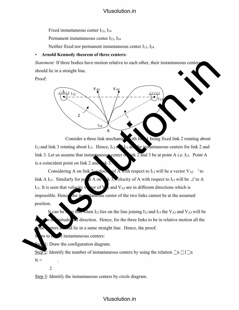
• Arnold Kennedy theorem of three centers:
Statement: If three bodies have motion relative to each other, their instantaneous centers
should lie in a straight line.
Proof:
Consider a three link mechanism with link 1 being fixed link 2 rotating about
I12 and link 3 rotating about I13. Hence, I12 and I13 are the instantaneous centers for link 2 and
link 3. Let us assume that instantaneous center of link 2 and 3 be at point A i.e. I23. Point A
is a coincident point on link 2 and link 3.
Considering A on link 2, velocity of A with respect to I12 will be a vector VA2 r to
link A I12. Similarly for point A on link 3, velocity of A with respect to I13 will be r to A
I13. It is seen that velocity vector of VA2 and VA3 are in different directions which is
impossible. Hence, the instantaneous center of the two links cannot be at the assumed
position.
It can be seen that when I23 lies on the line joining I12 and I13 the VA2 and VA3 will be
same in magnitude and direction. Hence, for the three links to be in relative motion all the
three centers should lie in a same straight line. Hence, the proof.
Steps to locate instantaneous centers:
Step 1: Draw the configuration diagram.
Step 2: Identify the number of instantaneous centers by using the relation n 1 n
N = .
2
Step 3: Identify the instantaneous centers by circle diagram.
I 12 V A3
2
V A2
I 13
I 23 A
3
1
Vtusolution.in
Vtusolution.in

vtuso
lution
.inStep 4: Locate all the instantaneous centers by making use of Kennedy’s theorem.
To illustrate the procedure let us consider an example.
A slider crank mechanism has lengths of crank and connecting rod equal to 200 mm
and 200 mm respectively locate all the instantaneous centers of the mechanism for the
position of the crank when it has turned through 30o from IOC. Also find velocity of slider
and angular velocity of connecting rod if crank rotates at 40 rad/sec.
Step 1: Draw configuration diagram to a suitable scale.
Step 2: Determine the number of links in the mechanism and find number of instantaneous
centers. n 1 n N =
2
4 4 1
n = 4 links N = = 6
Step 3: Identify instantaneous centers. o Suit it is a 4-bar link the
resulting figure will be a square.
1 I12 2
2
30 o
I 12
I 12
4
B
I 13
A 3
800 I 23 200 2
I 24
O 1 1
I 14 to I 14 to
Vtusolution.in
Vtusolution.in

vtuso
lution
.in I41 I23 OR
4 I34 3
o Locate fixed and permanent instantaneous centers. To locate neither fixed nor
permanent instantaneous centers use Kennedy’s three centers theorem.
Step 4: Velocity of different points. Va = 2 AI12 = 40 x
0.2 = 8 m/s also Va = 2 x A13
3 = Va
AI13
Vb = 3 x BI13 = Velocity of slider.
I 12 I 23 I 34
1 2 3 4
I 13 I 24
I 14
I 24
I 13
Vtusolution.in
Vtusolution.in

vtuso
lution
.in CHAPTER – 5
Gears Trains
A gear train is two or more gear working together by meshing their teeth and turning each
other in a system to generate power and speed. It reduces speed and increases torque. To
create large gear ratio, gears are connected together to form gear trains. They often consist of
multiple gears in the train.
The most common of the gear train is the gear pair connecting parallel shafts. The teeth of
this type can be spur, helical or herringbone. The angular velocity is simply the reverse of the
tooth ratio.
Any combination of gear wheels employed to transmit motion from one
shaft to the other is called a gear train. The meshing of two gears may be
idealized as two smooth discs with their edges touching and no slip between
them. This ideal diameter is called the Pitch Circle Diameter (PCD) of the
gear.
Simple Gear Trains
The typical spur gears as shown in diagram. The direction of rotation is reversed from one
gear to another. It has no affect on the gear ratio. The teeth on the gears must all be the same
size so if gear A advances one tooth, so does B and C.
t = number of teeth on the gear,
D = Pitch circle diameter, N = speed in rpm
D
m = module =
t
and module must be the same for all
gears otherwise they would not mesh.
DA DB D m = = = C
tA tB tC
DA = m tA; DB = m tB and DC = m tC
= angular velocity.
GEAR 'A' GEAR 'B' GEAR 'C'
D
Vtusolution.in
Vtusolution.in
vtuso
lution
.inv = linear velocity on the circle. v = = r (Idler gear)
2
Application:
a) to connect gears where a large center distance is required
b) to obtain desired direction of motion of the driven gear ( CW or CCW)
c) to obtain high speed ratio
Torque & Efficiency
The power transmitted by a torque T N-m applied to a shaft rotating at N rev/min is given
by:
P 2 NT
60
In an ideal gear box, the input and output powers are the same so;
P 2 N1T1 2 N2 T2
60 60
T2 N1 GR
N1T1 N2 T2
T1 N2
It follows that if the speed is reduced, the torque is increased and vice versa. In a real gear
box, power is lost through friction and the power output is smaller than the power input. The
efficiency is defined as:
Power out 2 N2T2 60 N2T2
Power In 2 N1T1 60 N1T1
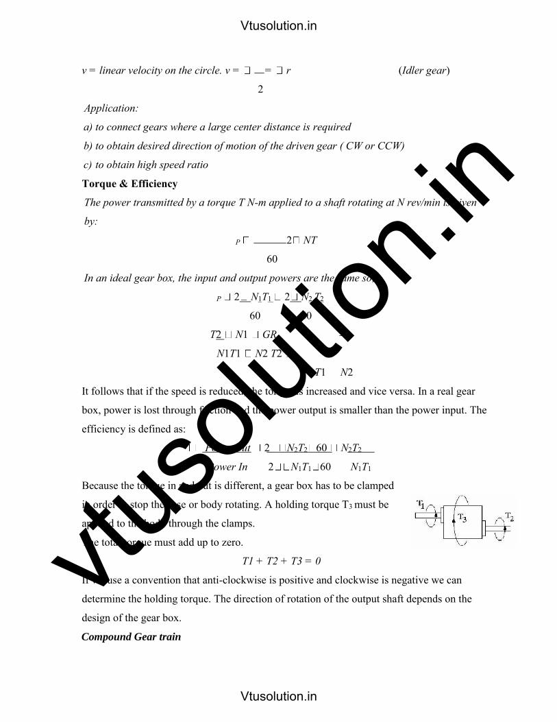
Because the torque in and out is different, a gear box has to be clamped
in order to stop the case or body rotating. A holding torque T3 must be
applied to the body through the clamps.
The total torque must add up to zero.
T1 + T2 + T3 = 0
If we use a convention that anti-clockwise is positive and clockwise is negative we can
determine the holding torque. The direction of rotation of the output shaft depends on the
design of the gear box.
Compound Gear train
Vtusolution.in
Vtusolution.in

vtuso
lution
.inCompound gears are simply a chain of simple gear trains with the input of the second
being the output of the first. A chain of two pairs is shown below. Gear B is the output
of the first pair and gear C is the input of the second pair. Gears B and C are locked to
the same shaft and revolve at the same speed.
For large velocities ratios, compound gear train
arrangement is preferred.
The velocity of each tooth on A and B are the same
GEAR 'D' so: A tA = B tB -as they are simple gears.
Likewise for C and D, C tC = D tD.
Reverted Gear train
The driver and driven axes lies on the same line. These
are used in speed reducers, clocks and machine tools.
GR NA tB tD
ND tA tC
If R and T=Pitch circle radius & number of teeth of the gear
RA + RB = RC + RD and tA + tB = tC + tD
Vtusolution.in
Vtusolution.in

vtuso
lution
.in
Observe point p and you will see that gear B also revolves once on its own axis. Any object
orbiting around a center must rotate once. Now consider that B is free to rotate on its shaft
and meshes with C.
Suppose the arm is held stationary and gear C is rotated once. B spins about its own center
and the
Now consider that C is unable to rotate and the arm A is revolved once. Gear B will revolve
Vtusolution.in
Vtusolution.in
vtuso
lution
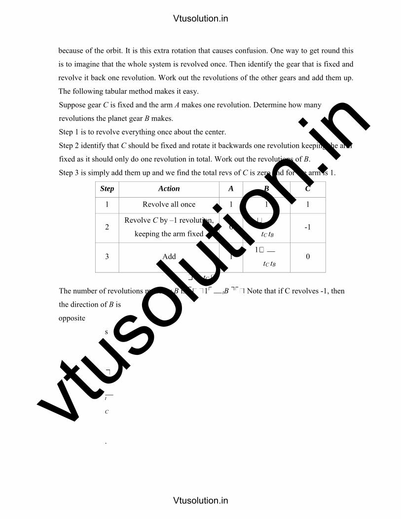
.inbecause of the orbit. It is this extra rotation that causes confusion. One way to get round this
is to imagine that the whole system is revolved once. Then identify the gear that is fixed and
revolve it back one revolution. Work out the revolutions of the other gears and add them up.
The following tabular method makes it easy.
Suppose gear C is fixed and the arm A makes one revolution. Determine how many
revolutions the planet gear B makes.
Step 1 is to revolve everything once about the center.
Step 2 identify that C should be fixed and rotate it backwards one revolution keeping the arm
fixed as it should only do one revolution in total. Work out the revolutions of B.
Step 3 is simply add them up and we find the total revs of C is zero and for the arm is 1.
Step Action A B C
1 Revolve all once 1 1 1
2 Revolve C by –1 revolution,
keeping the arm fixed 0
tC tB -1
3 Add 1 1
tC tB 0
tC
The number of revolutions made by B is 1 tB Note that if C revolves -1, then
the direction of B is
opposite
s
o
t
C
.
Vtusolution.in
Vtusolution.in

vtuso
lution
.int
B
Example: A simple epicyclic gear has a fixed sun gear with 100 teeth and a planet gear with
50 teeth. If the arm is revolved once, how many times does the planet gear revolve?
Solution:
Step Action A B C
1 Revolve all once 1 1 1
2 Revolve C by –1 revolution,
keeping the arm fixed 0 -1
3 Add 1 3 0
Gear B makes 3 revolutions for every one of the arm.
The design so far considered has no identifiable input and output. We need a design that puts
an input and output shaft on the same axis. This can be done several ways.
Problem 1: In an ecicyclic gear train shown in figure, the arm A is fixed to the shaft S. The
wheel B having 100 teeth rotates freely on the shaft S. The wheel F having 150 teeth driven
separately. If the arm rotates at 200 rpm and wheel F at 100 rpm in the same direction; find
(a) number of teeth on the gear C and (b) speed of wheel B.
Solution:
TB=100; TF=150; NA=200rpm; NF=100rpm:
Vtusolution.in
Vtusolution.in
vtuso
lution
.inSince the module is same for all gears : the number
of teeth on the gearsis proportional to the pitch cirlce:
The gear B and gear F rotates in the opposite directions:
The Gear B rotates at 350 rpm in the same direction of gears F and Arm A.
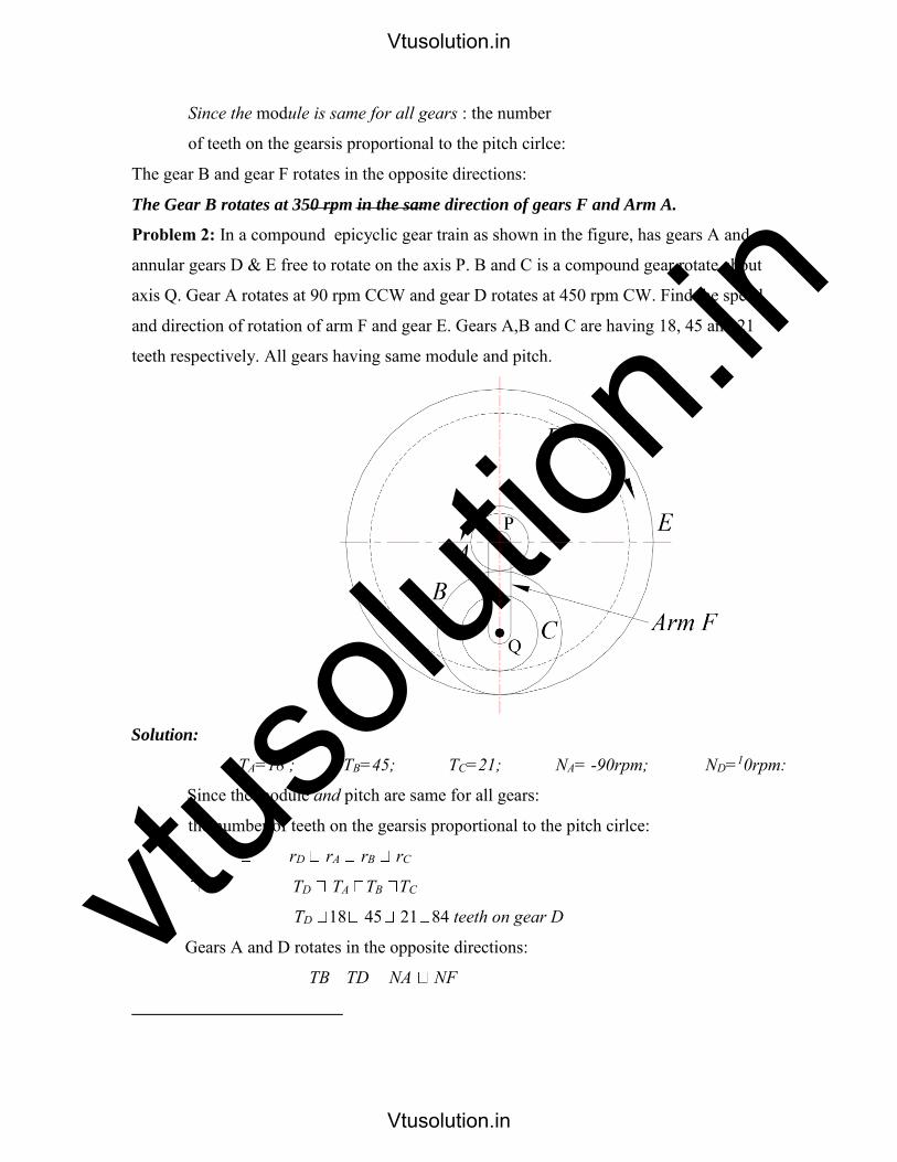
Problem 2: In a compound epicyclic gear train as shown in the figure, has gears A and an
annular gears D & E free to rotate on the axis P. B and C is a compound gear rotate about
axis Q. Gear A rotates at 90 rpm CCW and gear D rotates at 450 rpm CW. Find the speed
and direction of rotation of arm F and gear E. Gears A,B and C are having 18, 45 and 21
teeth respectively. All gears having same module and pitch.
Solution:
TA=18 ; TB=45; TC=21; NA= -90rpm; ND=10rpm:
Since the module and pitch are same for all gears:
the number of teeth on the gearsis proportional to the pitch cirlce:
rD rA rB rC
TD TA TB TC
TD 18 45 21 84 teeth on gear D
Gears A and D rotates in the opposite directions:
TB TD NA NF
Vtusolution.in
Vtusolution.in

vtuso
lution
.inProblem 3: In an epicyclic gear of sun and planet type shown in figure 3, the pitch circle
diameter of the annular wheel A is to be nearly 216mm and module 4mm. When the annular
ring is stationary, the spider that carries three planet wheels P of equal size to make one
revolution for every five revolution of the driving spindle carrying the sun wheel.
Determine the number of teeth for all the wheels and the exact pitch circle diameter of the
annular wheel. If an input torque of 20 N-m is applied to the spindle carrying the sun wheel,
determine the fixed torque on the annular wheel.
Solution: Module being the same for all the meshing gears:
Operation Spider
arm L
Sun Wheel S
TS
Planet wheel P
TP
Annular wheel A
TA = 54
Arm L is fixed &
Sun wheel S is
given +1
revolution
0 +1 TS TP
TS TP
TS
TP TA TA
Multiply by m
(S rotates through
m revolution)
0 m
TS m
TP
TS m
TA
Add n revolutions
to all elements n m+n
n TS m
TP
n TS m
TA
Vtusolution.in
Vtusolution.in

vtuso
lution
.in
Problem 4: The gear train shown in figure 4 is used in
an indexing mechanism of a milling machine. The
drive is from gear wheels A and B to the bevel gear
wheel D through the gear train. The following table
gives the number of teeth on each gear.
How many revolutions does D makes for one Figure 4
revolution of A under the following situations:
a. If A and B are having the same speed
and same direction
b. If A and B are having the same speed and opposite direction
c. If A is making 72 rpm and B is at rest
d. If A is making 72 rpm and B 36 rpm in the same direction
Solution:
Gear D is external to the epicyclic train and thus C and D constitute an ordinary
train.
Operation Arm
C (60) E (28) F (24) A (72) B (72) G (28) H (24)
Arm or C is fixed
& wheel A is
given
+1 revolution
0 -1
28 7
24 6 +1 -1 +1
28 7
24 6
Multiply by m
(A rotates through
m revolution)
0 -m m +m -m +m m
Add n revolutions
to all elements n n - m n m n + m n - m n + m n m
(i) For one revolution of A: n + m = 1 (1)
Vtusolution.in
Vtusolution.in

vtuso
lution
.inFor A and B for same speed and direction: n + m = n – m (2)
From (1) and (2): n = 1 and m = 0
If C or arm makes one revolution, then revolution made by D is given by:
ND TC 60
2
NC TD 30
ND 2NC
(ii) A and B same speed, opposite direction: (n + m) = - (n – m) (3) n = 0; m
= 1
When C is fixed and A makes one revolution, D does not make any revolution.
(iii) A is making 72 rpm: (n + m) = 72
B at rest (n – m) = 0 n = m = 36 rpm
C makes 36 rpm and D makes 36 72 rpm
(iv) A is making 72 rpm and B making 36 rpm
(n + m) = 72 rpm and (n – m) = 36
rpm
(n + (n – m)) = 72; n = 54
D makes 54 108 rpm
Problem 5: Figure 5 shows a compound
epicyclic gear train, gears S1 and S2 being rigidly
attached to the shaft Q. If the shaft P rotates at
1000 rpm clockwise, while the
Q
annular A2 is driven in counter clockwise
direction at 500 rpm, determine the speed and
direction of rotation of shaft Q. The number of
teeth in the wheels are S1 = 24; S2 = 40;
A1 = 100; A2 = 120.
Solution: Consider the gear train P A1 S1:
Vtusolution.in
Vtusolution.in

vtuso
lution
.inOperation
Arm
P
A1
(100) S1 (24)
OR Operation
Arm
P
A1
(100) S1 (24)
Arm P is fixed &
wheel A1 is given
+1 revolution
0 +1
100 P1
P1 24
Arm P is fixed
& wheel A1 is
given -1
revolution
0 -1
A1
P1
P1 S1
A1
S1
Multiply by m
(A1 rotates through
m revolution)
0 +m m
0 -1
100 25
24 6
Add n revolutions
to all elements n n+ m n m
Add +1
revolutions to
all elements
+1 0 1
If A1 is fixed: n+ m; gives n = - m
Now consider whole gear train:
Operation A1
(100)
A2
(120)
S1 (24), S2 (40)
and Q Arm P
A1 is fixed &
wheel A2 is given
+1 revolution
0 +1
120 P2
P2 40
3
3
Multiply by m
(A1 rotates through
m revolution)
0 +m 3m m
Add n revolutions
to all elements n n+ m n 3m n m
When P makes 1000 rpm: n m = 1000
(1) and A2 makes – 500 rpm: n+ m = -500 (2)
from (1) and (2): 500 m m 1000
Vtusolution.in
Vtusolution.in

vtuso
lution
.in31 1000 500 31 49m
m 949rpm
and n 949 500 449rpm
NQ = n – 3 m = 449 – (3 -949) = 3296 rpm
Vtusolution.in
Vtusolution.in

vtuso
lution
.inChapter 6- SPUR GEARS
Spur gears: Spur gears are the most common type of gears. They have straight teeth, and
are mounted on parallel shafts. Sometimes, many spur gears are used at once to create
very large gear reductions. Each time a gear tooth engages a tooth on the other gear,
the teeth collide, and this impact makes a noise. It also increases the stress on the gear
teeth. To reduce the noise and stress in the gears, most of the gears in your car are
helical.
Spur gears (Emerson Power Transmission Corp)
External contact Internal contact
Spur gears are the most commonly used gear type. They are characterized by teeth,
which are perpendicular to the face of the gear. Spur gears are most commonly available,
and are generally the least expensive.
• Limitations: Spur gears generally cannot be used when a direction change between
the two shafts is required.
• Advantages: Spur gears are easy to find, inexpensive, and efficient.
2. Parallel helical gears: The teeth on helical gears are cut at an angle to the face of the
gear. When two teeth on a helical gear system engage, the contact starts at one end of
the tooth and gradually spreads as the gears rotate, until the two teeth are in full
engagement.
Helical gears
Vtusolution.in
Vtusolution.in

vtuso
lution
.in(Emerson Power Transmission Corp) Herringbone gears
This gradual engagement makes helical gears operate much more smoothly and quietly than
spur gears. For this reason, helical gears are used in almost all car transmission.
Because of the angle of the teeth on helical gears, they create a thrust load on the gear when
they mesh. Devices that use helical gears have bearings that can support this thrust load.
One interesting thing about helical gears is that if the angles of the gear teeth are correct,
they can be mounted on perpendicular shafts, adjusting the rotation angle by 90 degrees.
Helical gears to have the following differences from spur gears of the same size:
o Tooth strength is greater because the teeth are longer,
o Greater surface contact on the teeth allows a helical gear to carry more load than a spur
gear
o The longer surface of contact reduces the efficiency of a helical gear relative to a spur
gear
Rack and pinion (The rack is like a gear whose axis is at
infinity.): Racks are straight gears that are used to convert
rotational motion to translational motion by means of a
gear mesh. (They are in theory a gear with an infinite pitch
diameter). In theory, the torque and angular velocity of the
pinion gear are related to the Force and the velocity of the rack by the radius of the
pinion gear, as is shown.
Perhaps the most well-known application of a rack is the rack and pinion steering system
used on many cars in the past
Gears for connecting intersecting shafts: Bevel gears are useful when the direction of
a shaft's rotation needs to be changed. They are usually mounted on shafts that are 90
degrees apart, but can be designed to work at other angles as well.
The teeth on bevel gears can be straight, spiral or hypoid. Straight bevel gear teeth actually
have the same problem as straight spur gear teeth, as each tooth engages; it impacts the
corresponding tooth all at once.
Just like with spur gears, the solution to this problem is to curve the gear teeth. These spiral
teeth engage just like helical teeth: the contact starts at one end of the gear and
progressively spreads across the whole tooth.
Vtusolution.in
Vtusolution.in

vtuso
lution
.in
Straight bevel gears Spiral bevel gears
On straight and spiral bevel gears, the shafts must be perpendicular to each other, but they
must also be in the same plane. The hypoid gear, can engage with the axes in different
planes.
This feature is used in many car differentials. The ring gear of the differential and the
input pinion gear are both hypoid. This allows the input pinion to be mounted lower than
the axis of the ring gear. Figure shows the input pinion engaging the ring gear of the
differential. Since the driveshaft of the car is connected to the input pinion, this also
lowers the driveshaft. This means that the driveshaft
Hypoid gears (Emerson Power Transmission Corp)
doesn't pass into the passenger compartment of the car as much, making more room for people
and cargo.
Neither parallel nor intersecting shafts: Helical gears may be used to mesh two shafts that
are not parallel, although they are still primarily use in parallel shaft applications. A special
application in which helical gears are used is a crossed gear mesh, in which the two shafts are
perpendicular to each other.
Vtusolution.in
Vtusolution.in
vtuso
lution
.in
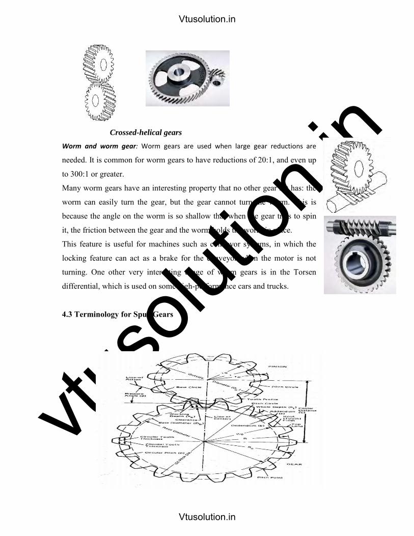
Crossed-helical gears
Worm and worm gear: Worm gears are used when large gear reductions are
needed. It is common for worm gears to have reductions of 20:1, and even up
to 300:1 or greater.
Many worm gears have an interesting property that no other gear set has: the
worm can easily turn the gear, but the gear cannot turn the worm. This is
because the angle on the worm is so shallow that when the gear tries to spin
it, the friction between the gear and the worm holds the worm in place.
This feature is useful for machines such as conveyor systems, in which the
locking feature can act as a brake for the conveyor when the motor is not
turning. One other very interesting usage of worm gears is in the Torsen
differential, which is used on some high-performance cars and trucks.
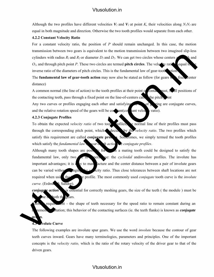
4.3 Terminology for Spur Gears
Vtusolution.in
Vtusolution.in

vtuso
lution
.in Addendum: The radial distance between the Pitch Circle and the top of the teeth.
Arc of Action: Is the arc of the Pitch Circle between the beginning and the end of the engagement of a given pair of teeth.
Arc of Approach: Is the arc of the Pitch Circle between the first point of contact of the gear teeth and the Pitch Point.
Arc of Recession: That arc of the Pitch Circle between the Pitch Point and the last point of contact of the gear teeth.
Backlash: Play between mating teeth.
Base Circle: The circle from which is generated the involute curve upon which the tooth profile is based.
Center Distance: The distance between centers of two gears.
Chordal Addendum: The distance between a chord, passing through the points where the Pitch Circle crosses the tooth profile, and the tooth top.
Chordal Thickness: The thickness of the tooth measured along a chord passing through the points where the Pitch Circle crosses the tooth profile.
Circular Pitch: Millimeter of Pitch Circle circumference per tooth.
Circular Thickness: The thickness of the tooth measured along an arc following the Pitch Circle
Clearance: The distance between the top of a tooth and the bottom of the space into which it fits on the meshing gear.
Contact Ratio: The ratio of the length of the Arc of Action to the Circular Pitch.
Dedendum: The radial distance between the bottom of the tooth to pitch circle.
Diametral Pitch: Teeth per mm of diameter.
Face: The working surface of a gear tooth, located between the pitch diameter and the top of the tooth.
Face Width: The width of the tooth measured parallel to the gear axis.
Flank: The working surface of a gear tooth, located between the pitch diameter and the bottom of the teeth
Gear: The larger of two meshed gears. If both gears are the same size, they are both called "gears".
Land: The top surface of the tooth.
Vtusolution.in
Vtusolution.in

vtuso
lution
.inLine of Action: That line along which the point of contact between gear teeth travels, between the first point of contact and the last.
Module: Millimeter of Pitch Diameter to Teeth.
Pinion: The smaller of two meshed gears.
Pitch Circle: The circle, the radius of which is equal to the distance from the center of the gear to the pitch point.
Diametral pitch: Teeth per millimeter of pitch diameter.
Pitch Point: The point of tangency of the pitch circles of two meshing gears, where the Line of Centers crosses the pitch circles.
Pressure Angle: Angle between the Line of Action and a line perpendicular to the Line of Centers.
Profile Shift: An increase in the Outer Diameter and Root Diameter of a gear, introduced to lower the practical tooth number or acheive a non-standard Center Distance.
Ratio: Ratio of the numbers of teeth on mating gears.
Root Circle: The circle that passes through the bottom of the tooth spaces.
Root Diameter: The diameter of the Root Circle.
Working Depth: The depth to which a tooth extends into the space between teeth on the mating gear.
4.2 Gear-Tooth Action
4.2.1 Fundamental Law of Gear-Tooth Action
Figure 5.2 shows two mating gear teeth, in
which
• Tooth profile 1 drives tooth profile 2 by acting
at the instantaneous contact point K.
• N1N2 is the common normal of the two profiles.
• N1 is the foot of the perpendicular from O1 to
N1N2
• N2 is the foot of the perpendicular from O2 to
N1N2.
Vtusolution.in
Vtusolution.in
vtuso
lution
.inAlthough the two profiles have different velocities V1 and V2 at point K, their velocities along N1N2 are
equal in both magnitude and direction. Otherwise the two tooth profiles would separate from each other.
4.2.2 Constant Velocity Ratio
For a constant velocity ratio, the position of P should remain unchanged. In this case, the motion
transmission between two gears is equivalent to the motion transmission between two imagined slip-less
cylinders with radius R1 and R2 or diameter D1 and D2. We can get two circles whose centers are at O1 and
O2, and through pitch point P. These two circles are termed pitch circles. The velocity ratio is equal to the
inverse ratio of the diameters of pitch circles. This is the fundamental law of gear-tooth action.
The fundamental law of gear-tooth action may now also be stated as follow (for gears with fixed center
distance)
A common normal (the line of action) to the tooth profiles at their point of contact must, in all positions of
the contacting teeth, pass through a fixed point on the line-of-centers called the pitch point
Any two curves or profiles engaging each other and satisfying the law of gearing are conjugate curves,
and the relative rotation speed of the gears will be constant(constant velocity ratio).
4.2.3 Conjugate Profiles
To obtain the expected velocity ratio of two tooth profiles, the normal line of their profiles must pass
through the corresponding pitch point, which is decided by the velocity ratio. The two profiles which
satisfy this requirement are called conjugate profiles. Sometimes, we simply termed the tooth profiles
which satisfy the fundamental law of gear-tooth action the conjugate profiles.
Although many tooth shapes are possible for which a mating tooth could be designed to satisfy the
fundamental law, only two are in general use: the cycloidal andinvolute profiles. The involute has
important advantages; it is easy to manufacture and the center distance between a pair of involute gears
can be varied without changing the velocity ratio. Thus close tolerances between shaft locations are not
required when using the involute profile. The most commonly used conjugate tooth curve is the involute
curve. (Erdman & Sandor).
conjugate action : It is essential for correctly meshing gears, the size of the teeth ( the module ) must be
the same for both the gears.
Another requirement - the shape of teeth necessary for the speed ratio to remain constant during an
increment of rotation; this behavior of the contacting surfaces (ie. the teeth flanks) is known as conjugate
action.
4.3 Involute Curve
The following examples are involute spur gears. We use the word involute because the contour of gear
teeth curves inward. Gears have many terminologies, parameters and principles. One of the important
concepts is the velocity ratio, which is the ratio of the rotary velocity of the driver gear to that of the
driven gears.
Vtusolution.in
Vtusolution.in

vtuso
lution
.in
4.1 Generation of the Involute Curve
The curve most commonly used for gear-tooth
profiles is the involute of a circle. This involute
curve is the path traced by a point on a line as the line
rolls without slipping on the circumference of a
circle. It may also be defined as a path traced by the
end of a string, which is originally wrapped on a
circle when the string is unwrapped from the
circle. The circle from which the involute is derived is called the base circle.
Figure 4.3 Involute curve
4.2 Properties of Involute Curves
1. The line rolls without slipping on the circle.
2. For any instant, the instantaneous center of the motion of the line is its point of tangent with the circle.
Note: We have not defined the term instantaneous center previously. The instantaneous center or
instant center is defined in two ways.
1. When two bodies have planar relative motion, the instant center is a point on one body about which
the other rotates at the instant considered.
2. When two bodies have planar relative motion, the instant center is the point at which the bodies are
relatively at rest at the instant considered.
3. The normal at any point of an involute is tangent to the base circle. Because of the property (2) of the
involute curve, the motion of the point that is tracing the involute is perpendicular to the line at any
instant, and hence the curve traced will also be perpendicular to the line at any instant.
There is no involute curve within the base circle.
Cycloidal profile:
Vtusolution.in
Vtusolution.in

vtuso
lution
.inEpicycliodal Profile:
Hypocycliodal Profile:
The involute profile of gears has important advantages;
• It is easy to manufacture and the center distance between a pair of involute gears can be varied
without changing the velocity ratio. Thus close tolerances between shaft locations are not
required. The most commonly used conjugate tooth curve is the involute curve. (Erdman &
Sandor).
2. In involute gears, the pressure angle, remains constant between the point of tooth engagement
and disengagement. It is necessary for smooth running and less wear of gears.
But in cycloidal gears, the pressure angle is maximum at the beginning of engagement, reduces to zero
at pitch point, starts increasing and again becomes maximum at the end of engagement. This results in
less smooth running of gears.
3. The face and flank of involute teeth are generated by a single curve where as in cycloidalgears,
double curves (i.e. epi-cycloid and hypo-cycloid) are required for the face and flank respectively. Thus
the involute teeth are easy to manufacture than cycloidal teeth.
In involute system, the basic rack has straight teeth and the same can be cut with simple tools.
Advantages of Cycloidal gear teeth:
1. Since the cycloidal teeth have wider flanks, therefore the cycloidal gears are stronger than the involute
gears, for the same pitch. Due to this reason, the cycloidal teeth are preferred specially for cast teeth.
Vtusolution.in
Vtusolution.in

vtuso
lution
.in2. In cycloidal gears, the contact takes place between a convex flank and a concave surface, where as in
involute gears the convex surfaces are in contact. This condition results in less wear in cycloidal gears
as compared to involute gears. However the difference in wear is negligible
3. In cycloidal gears, the interference does not occur at all. Though there are advantages of cycloidal gears
but they are outweighed by the greater simplicity and flexibility of the involute gears.
Properties of involute teeth:
1. A normal drawn to an involute at pitch point is a tangent to the base circle.
2. Pressure angle remains constant during the mesh of an involute gears.
3. The involute tooth form of gears is insensitive to the centre distance and depends only on the
dimensions of the base circle.
4. The radius of curvature of an involute is equal to the length of tangent to the base circle.
5. Basic rack for involute tooth profile has straight line form.
6. The common tangent drawn from the pitch point to the base circle of the two involutes is the line of
action and also the path of contact of the involutes.
7. When two involutes gears are in mesh and rotating, they exhibit constant angular velocity ratio and is
inversely proportional to the size of base circles. (Law of Gearing or conjugate action)
8. Manufacturing of gears is easy due to single curvature of profile.
System of Gear Teeth
The following four systems of gear teeth are commonly used in practice:
1. 14 ½O Composite system
2. 14 ½O Full depth involute system
3. 20O Full depth involute system
4. 20O Stub involute system
The 14½O composite system is used for general purpose gears.
It is stronger but has no interchangeability. The tooth profile of this system has cycloidal curves at the top
and bottom and involute curve at the middle portion.
The teeth are produced by formed milling cutters or hobs.
The tooth profile of the 14½O full depth involute system was developed using gear hobs for spur and
helical gears.
The tooth profile of the 20o full depth involute system may be cut by hobs.
The increase of the pressure angle from 14½o to 20o results in a stronger tooth, because the tooth acting as
a beam is wider at the base.
The 20o stub involute system has a strong tooth to take heavy loads.
Vtusolution.in
Vtusolution.in

vtuso
lution
.in4.2.2 Constant Velocity Ratio
For a constant velocity ratio, the position of P should remain unchanged. In this case, the motion
transmission between two gears is equivalent to the motion transmission between two imagined
slip-less cylinders with radius R1 and R2 or diameter D1 and D2. We can get two circles whose
centers are at O1 and O2, and through pitch point P. These two circles are termed pitch circles.
The velocity ratio is equal to the inverse ratio of the diameters of pitch circles. This is the
fundamental law of gear-tooth action.
The fundamental law of gear-tooth action may now also be stated as follow (for gears with
fixed center distance)
A common normal (the line of action) to the tooth profiles at their point of contact must, in all
positions of the contacting teeth, pass through a fixed point on the line-of-centers called the pitch
point
Any two curves or profiles engaging each other and satisfying the law of gearing are conjugate
curves, and the relative rotation speed of the gears will be constant(constant velocity ratio).
4.2.3 Conjugate Profiles
To obtain the expected velocity ratio of two tooth profiles, the normal line of their profiles must
pass through the corresponding pitch point, which is decided by the velocity ratio. The two
profiles which satisfy this requirement are called conjugate profiles. Sometimes, we simply
termed the tooth profiles which satisfy the fundamental law of gear-tooth action the conjugate
profiles.
Although many tooth shapes are possible for which a mating tooth could be designed to satisfy
the fundamental law, only two are in general use: the cycloidal andinvolute profiles. The involute
has important advantages; it is easy to manufacture and the center distance between a pair of
involute gears can be varied without changing the velocity ratio. Thus close tolerances between
shaft locations are not required when using the involute profile. The most commonly used
conjugate tooth curve is the involute curve. (Erdman & Sandor).
conjugate action : It is essential for correctly meshing gears, the size of the teeth ( the module )
must be the same for both the gears.
Another requirement - the shape of teeth necessary for the speed ratio to remain constant during
an increment of rotation; this behavior of the contacting surfaces (ie. the teeth flanks) is known
as conjugate action.
Vtusolution.in
Vtusolution.in
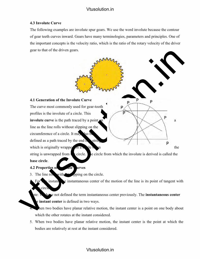
vtuso
lution
.in4.3 Involute Curve
The following examples are involute spur gears. We use the word involute because the contour
of gear teeth curves inward. Gears have many terminologies, parameters and principles. One of
the important concepts is the velocity ratio, which is the ratio of the rotary velocity of the driver
gear to that of the driven gears.
4.1 Generation of the Involute Curve
The curve most commonly used for gear-tooth
profiles is the involute of a circle. This
involute curve is the path traced by a point on a
line as the line rolls without slipping on the
circumference of a circle. It may also be
defined as a path traced by the end of a string,
which is originally wrapped on a circle when the
string is unwrapped from the circle. The circle from which the involute is derived is called the
base circle.
4.2 Properties of Involute Curves
3. The line rolls without slipping on the circle.
4. For any instant, the instantaneous center of the motion of the line is its point of tangent with
the circle.
Note: We have not defined the term instantaneous center previously. The instantaneous center
or instant center is defined in two ways.
4. When two bodies have planar relative motion, the instant center is a point on one body about
which the other rotates at the instant considered.
5. When two bodies have planar relative motion, the instant center is the point at which the
bodies are relatively at rest at the instant considered.
Vtusolution.in
Vtusolution.in

vtuso
lution
.in6. The normal at any point of an involute is tangent to the base circle. Because of the property
(2) of the involute curve, the motion of the point that is tracing the involute is perpendicular to
the line at any instant, and hence the curve traced will also be perpendicular to the line at any
instant.
There is no involute curve within the base circle.
Cycloidal profile:
Epicycliodal Profile:
Hypocycliodal Profile:
The involute profile of gears has important advantages;
• It is easy to manufacture and the center distance between a pair of involute gears can be
varied without changing the velocity ratio. Thus close tolerances between shaft locations
are not required. The most commonly used conjugate tooth curve is the involute curve.
(Erdman & Sandor).
Vtusolution.in
Vtusolution.in

vtuso
lution
.in4. In involute gears, the pressure angle, remains constant between the point of tooth
engagement and disengagement. It is necessary for smooth running and less wear of gears.
But in cycloidal gears, the pressure angle is maximum at the beginning of engagement,
reduces to zero at pitch point, starts increasing and again becomes maximum at the end of
engagement. This results in less smooth running of gears.
5. The face and flank of involute teeth are generated by a single curve where as in
cycloidalgears, double curves (i.e. epi-cycloid and hypo-cycloid) are required for the face and
flank respectively. Thus the involute teeth are easy to manufacture than cycloidal teeth.
In involute system, the basic rack has straight teeth and the same can be cut with simple tools.
Advantages of Cycloidal gear teeth:
9. Since the cycloidal teeth have wider flanks, therefore the cycloidal gears are stronger than
theinvolute gears, for the same pitch. Due to this reason, the cycloidal teeth are preferred
specially for cast teeth.
10. In cycloidal gears, the contact takes place between a convex flank and a concave surface,
where as in involute gears the convex surfaces are in contact. This condition results in less
wear in cycloidal gears as compared to involute gears. However the difference in wear is
negligible
11. In cycloidal gears, the interference does not occur at all. Though there are advantages of
cycloidal gears but they are outweighed by the greater simplicity and flexibility of the involute
gears.
Properties of involute teeth:
1. A normal drawn to an involute at pitch point is a tangent to the base circle.
2. Pressure angle remains constant during the mesh of an involute gears.
3. The involute tooth form of gears is insensitive to the centre distance and depends only on
thedimensions of the base circle.
12. The radius of curvature of an involute is equal to the length of tangent to the base circle.
13. Basic rack for involute tooth profile has straight line form.
14. The common tangent drawn from the pitch point to the base circle of the two involutes is
theline of action and also the path of contact of the involutes.
15. When two involutes gears are in mesh and rotating, they exhibit constant angular velocity
ratioand is inversely proportional to the size of base circles. (Law of Gearing or conjugate
action)
Vtusolution.in
Vtusolution.in

vtuso
lution
.in16. Manufacturing of gears is easy due to single curvature of profile.
System of Gear Teeth
The following four systems of gear teeth are commonly used in practice:
5. 14 ½O Composite system
6. 14 ½O Full depth involute system
7. 20O Full depth involute system
8. 20O Stub involute system
The 14½O composite system is used for general purpose gears.
It is stronger but has no interchangeability. The tooth profile of this system has cycloidal curves
at the top and bottom and involute curve at the middle portion.
The teeth are produced by formed milling cutters or hobs.
The tooth profile of the 14½O full depth involute system was developed using gear hobs for spur
and helical gears.
The tooth profile of the 20o full depth involute system may be cut by hobs.
The increase of the pressure angle from 14½o to 20o results in a stronger tooth, because the tooth
acting as a beam is wider at the base.
The 20o stub involute system has a strong tooth to take heavy loads.
Involutometry
The study of the geometry of the involute profile for gear teeth is called involumetry. Consider
an involute of base circle radius ra and two points B and C on the involute as shown in figure.
Draw normal to the involute from the points B and C. The normal BE and CF are tangents to the
Base circle.
Vtusolution.in
Vtusolution.in

vtuso
lution
.inLet ra= base circle radius of gear rb= radius of point B on the involute rc= radius of point C on the
involute and
From the properties of the Involute:
Arc AE = Length BE and
Arc AF = Length CF
2rc
Using this equation and knowing tooth thickness at any point on the tooth, it is possible to
calculate the thickness of the tooth at any point
Number of Pairs of Teeth in Contact
Continuous motion transfer requires two pairs of teeth in contact at the ends of the path of
contact, though there is only one pair in contact in the middle of the path, as in Figure.
The average number of teeth in contact is an important parameter - if it is too low due to the use
of inappropriate profile shifts or to an excessive centre distance.The manufacturing inaccuracies
may lead to loss of kinematic continuity - that is to impact, vibration and noise.
The average number of teeth in contact is also a guide to load sharing between teeth; it is termed
the contact ratio
Length of path of contact for Rack and Pinion:
R
r
Vtusolution.in
Vtusolution.in
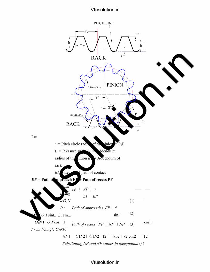
vtuso
lution
.in
Let
r = Pitch circle radius of the pinion = O1P
= Pressure angle ra. = Addendu m
radius of the pinion a = Addendum of
rack
EF = Length of path of contact
EF = Path of approach EP + Path of recess PF
From
triang
leO1N
P :
NP O1Psin rsin
O1N O1Pcos rcos
From triangle O1NF:
NF O1F2 O1N2 12 ra2 r2 cos2 12
Substituting NP and NF values in theequation (3)
sin AP a
EP EP
Path of approach EP a
sin
Path of recess PF NF NP
(1)
(2)
(3)
Vtusolution.in
Vtusolution.in
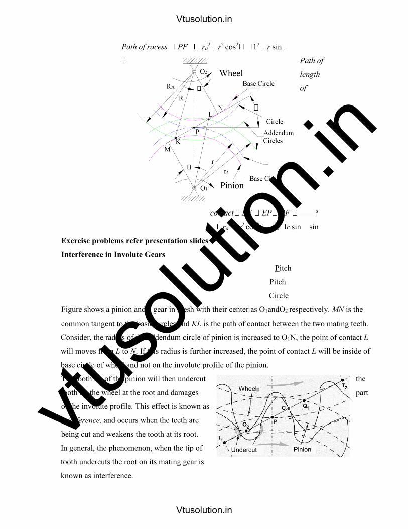
vtuso
lution
.inPath of racess PF ra
2 r2 cos2 12 r sin
Path of
length
of
contact EF EP PF a
ra2 r2 cos2 1
2 r sin sin
Exercise problems refer presentation slides
Interference in Involute Gears
Pitch
Pitch
Circle
Figure shows a pinion and a gear in mesh with their center as O1andO2 respectively. MN is the
common tangent to the basic circles and KL is the path of contact between the two mating teeth.
Consider, the radius of the addendum circle of pinion is increased to O1N, the point of contact L
will moves from L to N. If this radius is further increased, the point of contact L will be inside of
base circle of wheel and not on the involute profile of the pinion.
The tooth tip of the pinion will then undercut the
tooth on the wheel at the root and damages part
of the involute profile. This effect is known as
interference, and occurs when the teeth are
being cut and weakens the tooth at its root.
In general, the phenomenon, when the tip of
tooth undercuts the root on its mating gear is
known as interference.
Wheel
Undercut Pinion
Vtusolution.in
Vtusolution.in

vtuso
lution
.inSimilarly, if the radius of the addendum circles of the wheel increases beyond O2M, then the tip
of tooth on wheel will cause interference with the tooth on pinion. The points M and N are called
interference points.
Interference may be avoided if the path of the contact does not extend beyond interference
points. The limiting value of the radius of the addendum circle of the pinion is O1N and of the
wheel is O2M.
The interference may only be prevented, if the point of contact between the two teeth is always
on the involute profiles and if the addendum circles of the two mating gears cut the common
tangent to the base circles at the points of tangency.
When interference is just prevented, the maximum length of path of contact is MN.
Methods to avoid Interference
1. Height of the teeth may be reduced.
2. Under cut of the radial flank of the pinion.
3. Centre distance may be increased. It leads to increase in pressure angle.
4. By tooth correction, the pressure angle, centre distance and base circles remain unchanged,
buttooth thickness of gear will be greater than the pinion tooth thickness. Minimum
number of teeth on the pinion avoid Interference
The pinion turns clockwise and drives the gear as shown in Figure.
Points M and N are called interference points. i.e., if the contact takes place beyond M and N,
interference will occur.
The limiting value of addendum circle radius of pinion is O1N and the limiting value of
addendum circle radius of gear is O2M. Considering the critical addendum circle radius of gear,
the limiting number of teeth on gear can be calculated.
Let
Ф = pressure angle
R = pitch circle radius of gear = ½mT r =
pitch circle radius of pinion = ½mt T & t =
number of teeth on gear & pinion
m = module
aw = Addendum constant of gear (or) wheel ap = Addendum
constant of pinion aw. m = Addendum of gear ap. m = Addendum of
pinion
Vtusolution.in
Vtusolution.in

vtuso
lution
.inMinimum number of teeth on the wheel avoid Interference
From triangle O2MP, applying cosine rule and simplifying, The limiting radius of wheel addendum
circle:
Minimum number of teeth on the pinion for involute rack to avoid Interference
The rack is part of toothed wheel of infinite
diameter. The base circle diameter and
profile of the involute teeth are straight lines.
PITCH LINE
RACK
Let t= Minimum number of teeth on the pinion r=
Pitch circle radius of the pinion = ½ mt
= Pressure angle
AR.m= Addendum of rack
The straight profiles of the rack are tangential to the pinion profiles at the point of contact and
perpendicular to the tangent PM. Point L is the limit of interference.
Backlash:
The gap between the non-drive face of the pinion tooth and the adjacent wheel tooth is known as
backlash.
Vtusolution.in
Vtusolution.in
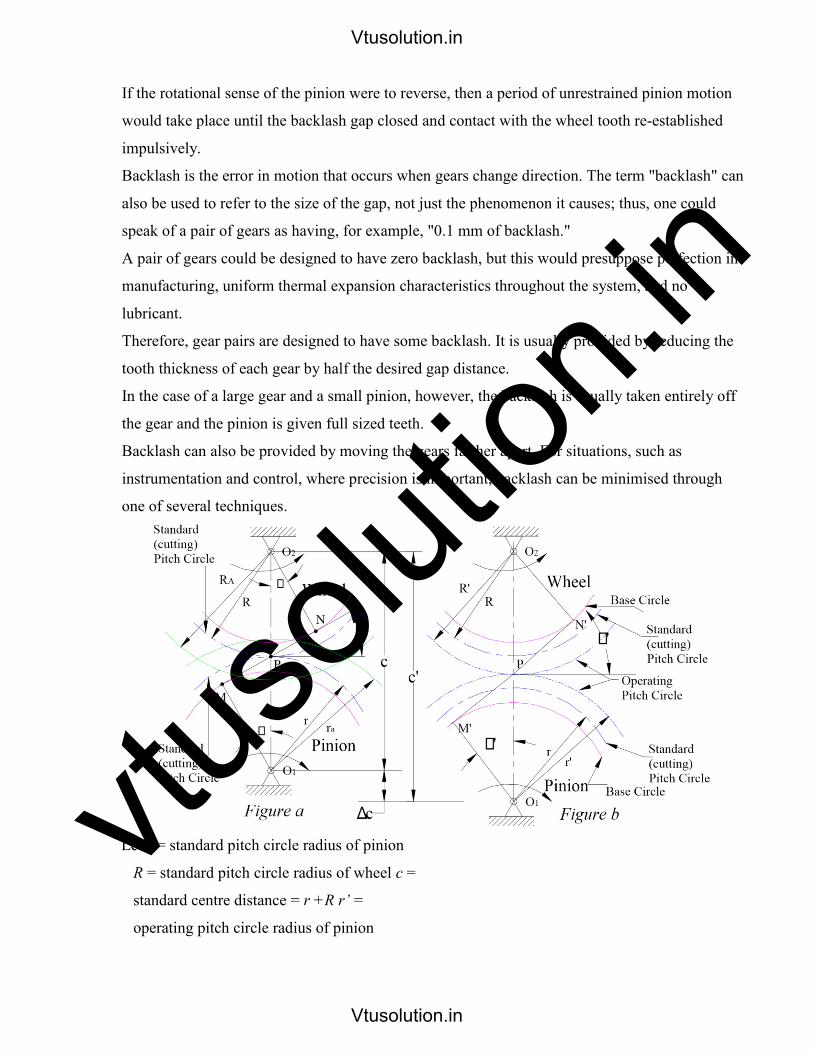
vtuso
lution
.inIf the rotational sense of the pinion were to reverse, then a period of unrestrained pinion motion
would take place until the backlash gap closed and contact with the wheel tooth re-established
impulsively.
Backlash is the error in motion that occurs when gears change direction. The term "backlash" can
also be used to refer to the size of the gap, not just the phenomenon it causes; thus, one could
speak of a pair of gears as having, for example, "0.1 mm of backlash."
A pair of gears could be designed to have zero backlash, but this would presuppose perfection in
manufacturing, uniform thermal expansion characteristics throughout the system, and no
lubricant.
Therefore, gear pairs are designed to have some backlash. It is usually provided by reducing the
tooth thickness of each gear by half the desired gap distance.
In the case of a large gear and a small pinion, however, the backlash is usually taken entirely off
the gear and the pinion is given full sized teeth.
Backlash can also be provided by moving the gears farther apart. For situations, such as
instrumentation and control, where precision is important, backlash can be minimised through
one of several techniques.
Let r = standard pitch circle radius of pinion
R = standard pitch circle radius of wheel c =
standard centre distance = r +R r’ =
operating pitch circle radius of pinion
Vtusolution.in
Vtusolution.in

vtuso
lution
.inR’ = operating pitch circle radius of wheel
c’ = operating centre distance = r’ + R’
Ф = Standard pressure angle
Ф’ = operating pressure angle h = tooth thickness of pinion on
standard pitch circle= p/2 h’ = tooth thickness of pinion on
operating pitch circle
Let
H = tooth thickness of gear on standard pitch circle
H1 = tooth thickness of gear on operating pitch circle p =
standard circular pitch = 2п r/ t = 2пR/T
p’ = operating circular pitch = 2п r1/t = 2пR1/T
∆C = change in centre distance B
= Backlash t = number of
teeth on pinion
T = number of teeth on gear.
Involute gears have the invaluable ability of providing conjugate action when the gears' centre
distance is varied either deliberately or involuntarily due to manufacturing and/or mounting
errors.
There is an infinite number of possible centre distances for a given pair of profile shifted gears,
however we consider only the particular case known as the extended centre distance.
Non Standard Gears:
The important reason for using non standard gears are to eliminate undercutting, to prevent
interference and to maintain a reasonable contact ratio.
The two main non- standard gear systems:
(1) Long and short Addendum system and
(2) Extended centre distance system.
Long and Short Addendum System:
The addendum of the wheel and the addendum of the pinion are generally made of equal lengths.
Here the profile/rack cutter is advanced to a certain increment towards the gear blank and the
same quantity of increment will be withdrawn from the pinion blank.
Vtusolution.in
Vtusolution.in
vtuso
lution
.inTherefore an increased addendum for the pinion and a decreased addendum for the gear is
obtained. The amount of increase in the addendum of the pinion should be exactly equal to the
addendum of the wheel is reduced.
The effect is to move the contact region from the pinion centre towards the gear centre, thus
reducing approach length and increasing the recess length. In this method there is no change in
pressure angle and the centre distance remains standard.
Extended centre distance system:
Reduction in interference with constant contact ratio can be obtained by increasing the centre
distance. The effect of changing the centre distance is simply in increasing the pressure angle.
In this method when the pinion is being cut, the profile cutter is withdrawn a certain amount from
the centre of the pinion so the addendum line of the cutter passes through the interference point
of pinion. The result is increase in tooth thickness and decrease in tooth space.
Now If the pinion is meshed with the gear, it will be found that the centre distance has been
increased because of the decreased tooth space. Increased centre distance will have two
undesirable effects.
Vtusolution.in
Vtusolution.in