ME44 KINEMATICS OF MACHINES -...
30
ME 44 Kinematics of Machines Chapter 4: Gears Dr. T.V.Govindaraju. SSEC 1 Dr.T.V.Govindaraju Principal, Shirdi Sai Engineering College Anekal, Bangalore-562 106 email: [email protected] ME44 KINEMATICS OF MACHINES
Transcript of ME44 KINEMATICS OF MACHINES -...
ME 44 Kinematics of Machines Chapter 4: Gears
Dr. T.V.Govindaraju. SSEC1
Dr.T.V.GovindarajuPrincipal, Shirdi Sai Engineering College
Anekal, Bangalore-562 106
email: [email protected]
ME44 KINEMATICS OF MACHINES
ME 44 Kinematics of Machines Chapter 4: Gears
Dr. T.V.Govindaraju. SSEC2
4.0 Gears:
Introduction: The slip and creep in the belt or rope drives is a common phenomenon, in thetransmission of motion or power between two shafts. The effect of slip is to reduce the velocityratio of the drive. In precision machine, in which a definite velocity ratio is importance (as inwatch mechanism, special purpose machines..etc), the only positive drive is by means of gears ortoothed wheels.
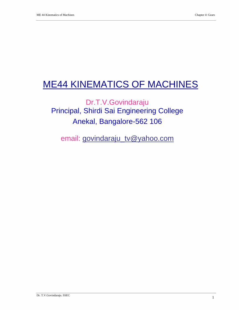
Friction Wheels: Kinematiclly, the motion andpower transmitted by gears is equivalent to thattransmitted by friction wheels or discs in contactwith sufficient friction between them. In order tounderstand motion transmitted by two toothedwheels, let us consider the two discs placed togetheras shown in the figure 4.1.
When one of the discs is rotated, the other disc will be rotate as long as the tangential forceexerted by the driving disc does not exceed the maximum frictional resistance between the twodiscs. But when the tangential force exceeds the frictional resistance, slipping will take placebetween the two discs. Thus the friction drive is not positive a drive, beyond certain limit.
Gears are machine elements that transmit motion by means of successively engaging teeth. Thegear teeth act like small levers. Gears are highly efficient (nearly 95%) due to primarily rollingcontact between the teeth, thus the motion transmitted is considered as positive.
Gears essentially allow positive engagement between teeth so high forces can be transmittedwhile still undergoing essentially rolling contact. Gears do not depend on friction and do bestwhen friction is minimized.
Some common places that gears can normally be found are:
Printing machinery parts Newspaper Industry Book binding machinesRotary die cuttingmachines
Plastics machinery builders Injection molding machinery
Blow molding machinery Motorcycle Transmissions (streetand race applications)
Heavy earth moving topersonal vehicles
Agricultural equipment Polymer pumps High volume water pumps formunicipalities
High volume vacuumpumps
Turbo boosters for automotiveapplications
Marine applications
Boat out drives Special offshore racing drivesystems
Canning and bottlingmachinery builders
Hoists and Cranes Commercial and Militaryoperations
Military offroad vehicles
Automotive prototype andreproduction
Low volume automotiveproduction
Stamping presses
Diesel engine builders Special gear box builders Many different specialmachine tool builders
Figure 4.1
ME 44 Kinematics of Machines Chapter 4: Gears
Dr. T.V.Govindaraju. SSEC3
4.1 Gear Classification: Gears may be classified according to the relative position of the axes ofrevolution. The axes may be
1. Gears for connecting parallel shafts,2. Gears for connecting intersecting shafts,3. Gears for neither parallel nor intersecting shafts.
Gears for connecting parallel shafts
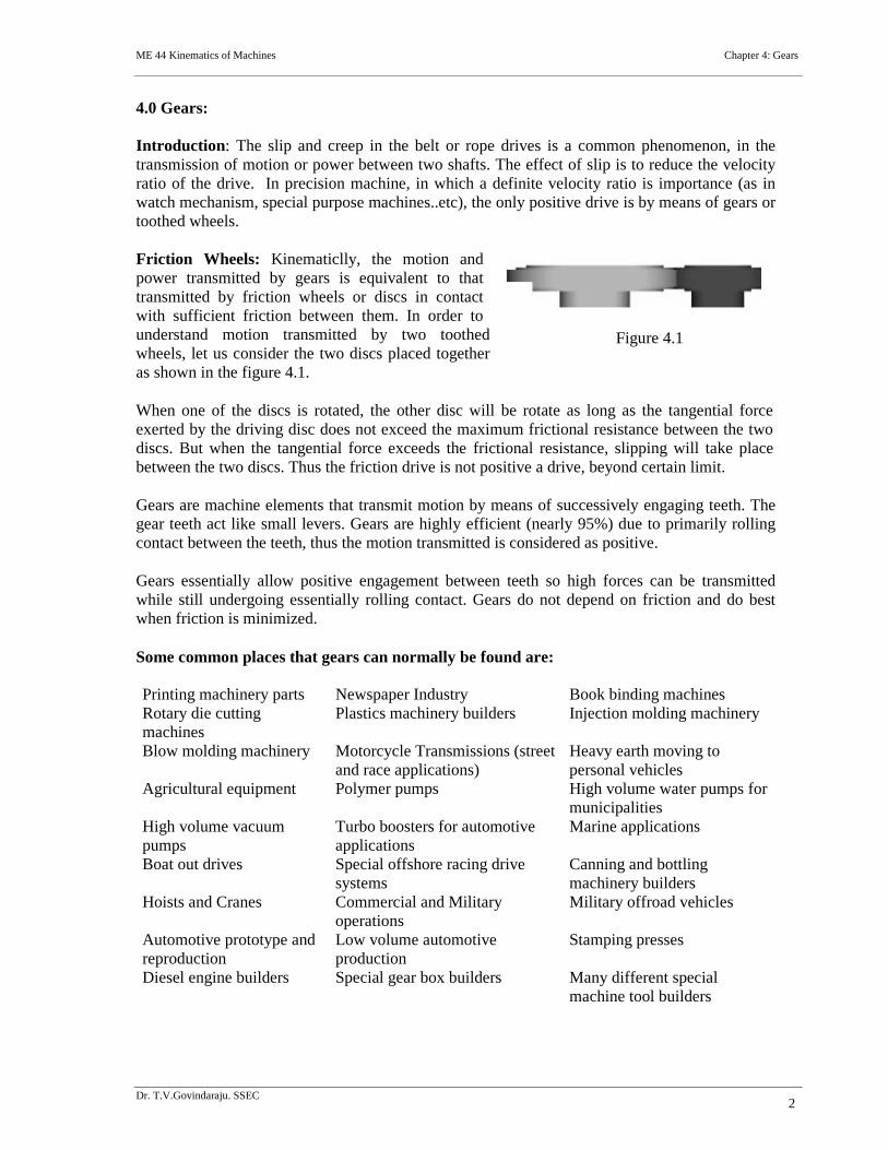
1. Spur gears: Spur gears are the most common type of gears. They have straight teeth, andare mounted on parallel shafts. Sometimes, many spur gears are used at once to create verylarge gear reductions. Each time a gear tooth engages a tooth on the other gear, the teethcollide, and this impact makes a noise. It also increases the stress on the gear teeth. Toreduce the noise and stress in the gears, most of the gears in your car are helical.
Spur gears are the most commonly used gear type. They are characterized by teeth, which areperpendicular to the face of the gear. Spur gears are most commonly available, and aregenerally the least expensive.
Limitations: Spur gears generally cannot be used when a direction change between the twoshafts is required.
Advantages: Spur gears are easy to find, inexpensive, and efficient.
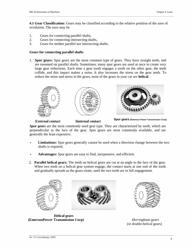
2. Parallel helical gears: The teeth on helical gears are cut at an angle to the face of the gear.When two teeth on a helical gear system engage, the contact starts at one end of the toothand gradually spreads as the gears rotate, until the two teeth are in full engagement.
Helical gears(EmersonPower Transmission Corp) Herringbone gears
(or double-helical gears)
External contact Iinternal contactSpur gears (Emerson Power Transmission Corp)
ME 44 Kinematics of Machines Chapter 4: Gears
Dr. T.V.Govindaraju. SSEC4
This gradual engagement makes helical gears operate much more smoothly and quietly than spurgears. For this reason, helical gears are used in almost all car transmission.
Because of the angle of the teeth on helical gears, they create a thrust load on the gear when theymesh. Devices that use helical gears have bearings that can support this thrust load.
One interesting thing about helical gears is that if the angles of the gear teeth are correct, theycan be mounted on perpendicular shafts, adjusting the rotation angle by 90 degrees.
Helical gears to have the following differences from spur gears of the same size:
o Tooth strength is greater because the teeth are longer,o Greater surface contact on the teeth allows a helical gear to carry more load than a spur
gearo The longer surface of contact reduces the efficiency of a helical gear relative to a spur
gear
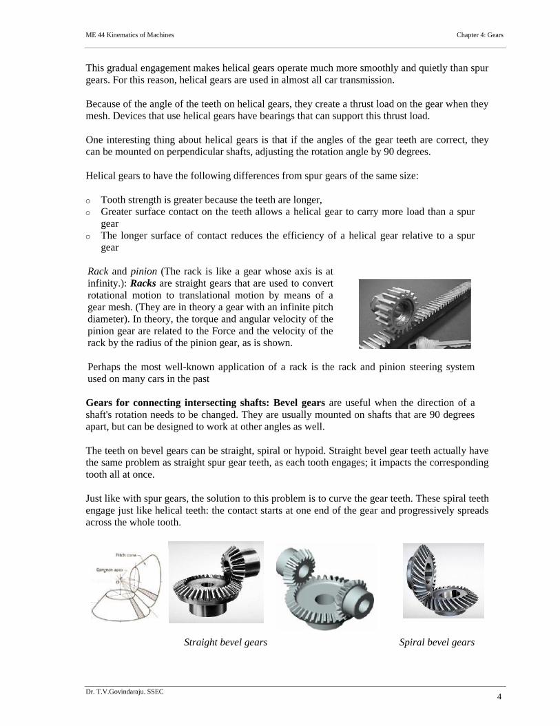
Rack and pinion (The rack is like a gear whose axis is atinfinity.): Racks are straight gears that are used to convertrotational motion to translational motion by means of agear mesh. (They are in theory a gear with an infinite pitchdiameter). In theory, the torque and angular velocity of thepinion gear are related to the Force and the velocity of therack by the radius of the pinion gear, as is shown.
Perhaps the most well-known application of a rack is the rack and pinion steering systemused on many cars in the past
Gears for connecting intersecting shafts: Bevel gears are useful when the direction of ashaft's rotation needs to be changed. They are usually mounted on shafts that are 90 degreesapart, but can be designed to work at other angles as well.
The teeth on bevel gears can be straight, spiral or hypoid. Straight bevel gear teeth actually havethe same problem as straight spur gear teeth, as each tooth engages; it impacts the correspondingtooth all at once.
Just like with spur gears, the solution to this problem is to curve the gear teeth. These spiral teethengage just like helical teeth: the contact starts at one end of the gear and progressively spreadsacross the whole tooth.
Straight bevel gears Spiral bevel gears
ME 44 Kinematics of Machines Chapter 4: Gears
Dr. T.V.Govindaraju. SSEC5
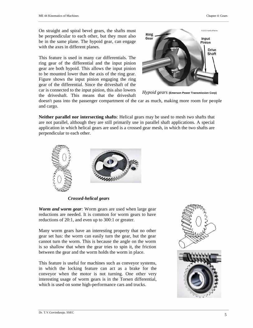
On straight and spiral bevel gears, the shafts mustbe perpendicular to each other, but they must alsobe in the same plane. The hypoid gear, can engagewith the axes in different planes.
This feature is used in many car differentials. Thering gear of the differential and the input piniongear are both hypoid. This allows the input pinionto be mounted lower than the axis of the ring gear.Figure shows the input pinion engaging the ringgear of the differential. Since the driveshaft of thecar is connected to the input pinion, this also lowersthe driveshaft. This means that the driveshaftdoesn't pass into the passenger compartment of the car as much, making more room for peopleand cargo.
Neither parallel nor intersecting shafts: Helical gears may be used to mesh two shafts thatare not parallel, although they are still primarily use in parallel shaft applications. A specialapplication in which helical gears are used is a crossed gear mesh, in which the two shafts areperpendicular to each other.
Crossed-helical gears
Worm and worm gear: Worm gears are used when large gearreductions are needed. It is common for worm gears to havereductions of 20:1, and even up to 300:1 or greater.
Many worm gears have an interesting property that no othergear set has: the worm can easily turn the gear, but the gearcannot turn the worm. This is because the angle on the wormis so shallow that when the gear tries to spin it, the frictionbetween the gear and the worm holds the worm in place.
This feature is useful for machines such as conveyor systems,in which the locking feature can act as a brake for theconveyor when the motor is not turning. One other veryinteresting usage of worm gears is in the Torsen differential,which is used on some high-performance cars and trucks.
Hypoid gears (Emerson Power Transmission Corp)
ME 44 Kinematics of Machines Chapter 4: Gears
Dr. T.V.Govindaraju. SSEC6
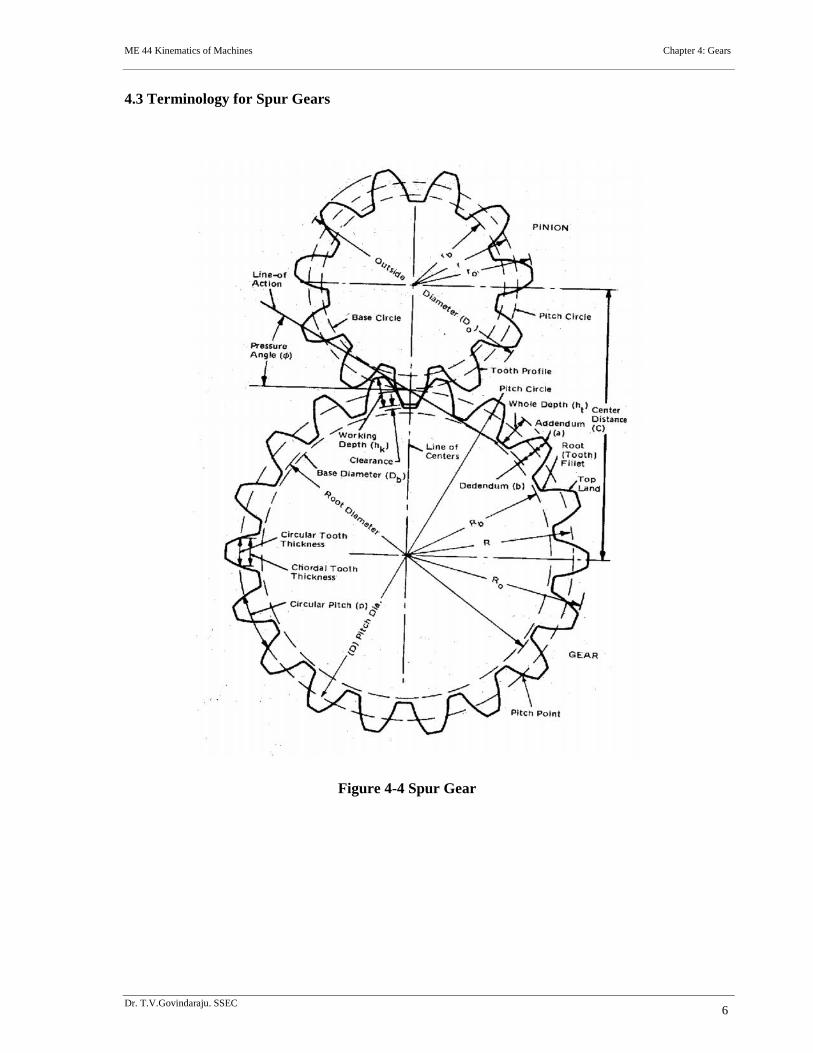
4.3 Terminology for Spur Gears
Figure 4-4 Spur Gear
ME 44 Kinematics of Machines Chapter 4: Gears
Dr. T.V.Govindaraju. SSEC7
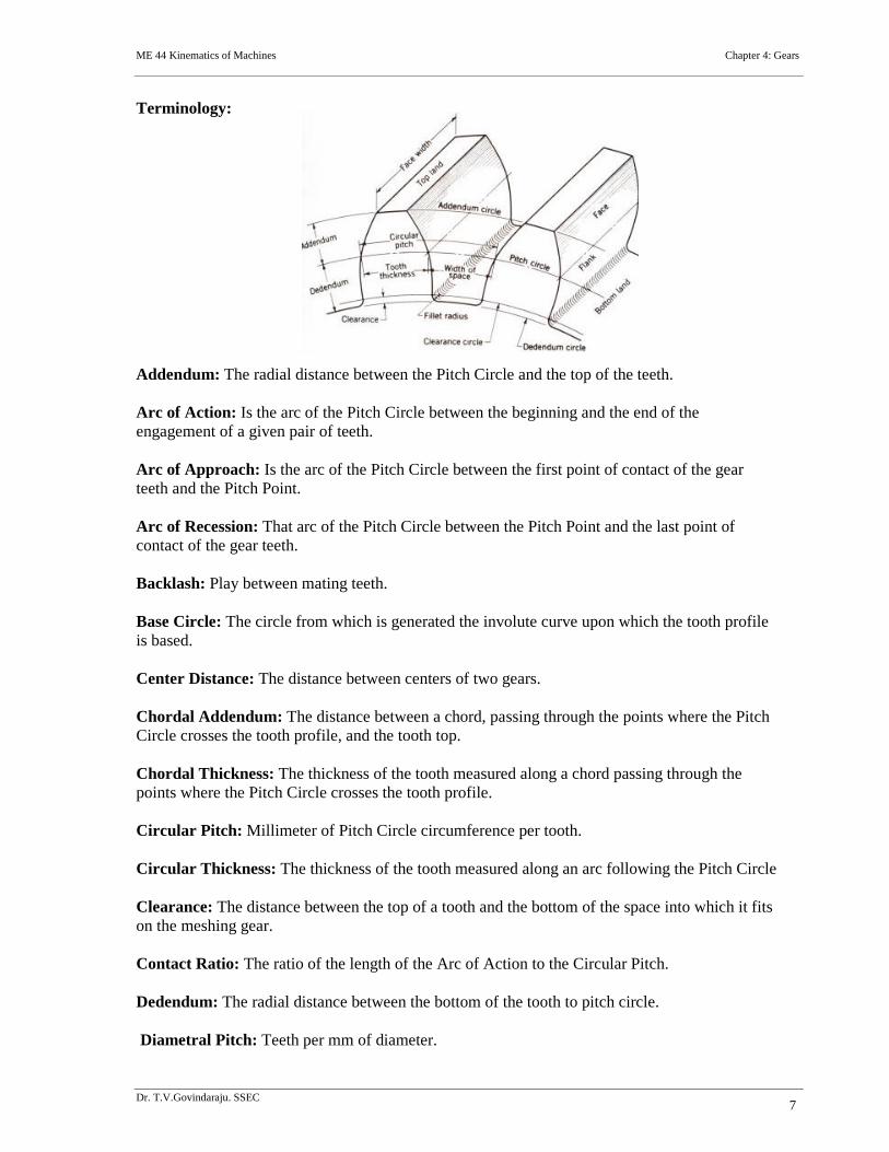
Terminology:
Addendum: The radial distance between the Pitch Circle and the top of the teeth.
Arc of Action: Is the arc of the Pitch Circle between the beginning and the end of theengagement of a given pair of teeth.
Arc of Approach: Is the arc of the Pitch Circle between the first point of contact of the gearteeth and the Pitch Point.
Arc of Recession: That arc of the Pitch Circle between the Pitch Point and the last point ofcontact of the gear teeth.
Backlash: Play between mating teeth.
Base Circle: The circle from which is generated the involute curve upon which the tooth profileis based.
Center Distance: The distance between centers of two gears.
Chordal Addendum: The distance between a chord, passing through the points where the PitchCircle crosses the tooth profile, and the tooth top.
Chordal Thickness: The thickness of the tooth measured along a chord passing through thepoints where the Pitch Circle crosses the tooth profile.
Circular Pitch: Millimeter of Pitch Circle circumference per tooth.
Circular Thickness: The thickness of the tooth measured along an arc following the Pitch Circle
Clearance: The distance between the top of a tooth and the bottom of the space into which it fitson the meshing gear.
Contact Ratio: The ratio of the length of the Arc of Action to the Circular Pitch.
Dedendum: The radial distance between the bottom of the tooth to pitch circle.
Diametral Pitch: Teeth per mm of diameter.
ME 44 Kinematics of Machines Chapter 4: Gears
Dr. T.V.Govindaraju. SSEC8
Face: The working surface of a gear tooth, located between the pitch diameter and the top of thetooth.
Face Width: The width of the tooth measured parallel to the gear axis.
Flank: The working surface of a gear tooth, located between the pitch diameter and the bottomof the teeth
Gear: The larger of two meshed gears. If both gears are the same size, they are both called"gears".
Land: The top surface of the tooth.
Line of Action: That line along which the point of contact between gear teeth travels, betweenthe first point of contact and the last.
Module: Millimeter of Pitch Diameter to Teeth.
Pinion: The smaller of two meshed gears.
Pitch Circle: The circle, the radius of which is equal to the distance from the center of the gearto the pitch point.
Diametral pitch: Teeth per millimeter of pitch diameter.
Pitch Point: The point of tangency of the pitch circles of two meshing gears, where the Line ofCenters crosses the pitch circles.
Pressure Angle: Angle between the Line of Action and a line perpendicular to the Line ofCenters.
Profile Shift: An increase in the Outer Diameter and Root Diameter of a gear, introduced tolower the practical tooth number or acheive a non-standard Center Distance.
Ratio: Ratio of the numbers of teeth on mating gears.
Root Circle: The circle that passes through the bottom of the tooth spaces.
Root Diameter: The diameter of the Root Circle.
Working Depth: The depth to which a tooth extends into the space between teeth on the matinggear.
ME 44 Kinematics of Machines Chapter 4: Gears
Dr. T.V.Govindaraju. SSEC9
4.2 Gear-Tooth Action
4.2.1 Fundamental Law of Gear-ToothAction
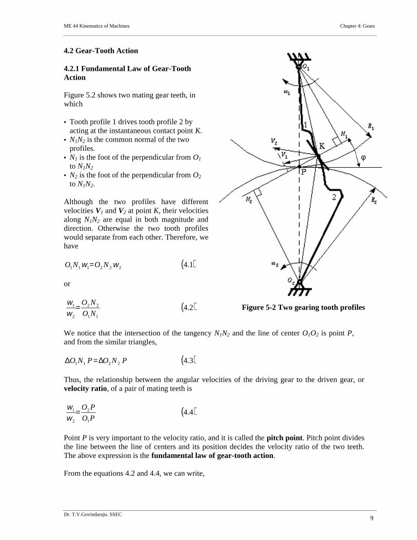
Figure 5.2 shows two mating gear teeth, inwhich
Tooth profile 1 drives tooth profile 2 byacting at the instantaneous contact point K.
N1N2 is the common normal of the twoprofiles.
N1 is the foot of the perpendicular from O1
to N1N2
N2 is the foot of the perpendicular from O2
to N1N2.
Although the two profiles have differentvelocities V1 and V2 at point K, their velocitiesalong N1N2 are equal in both magnitude anddirection. Otherwise the two tooth profileswould separate from each other. Therefore, wehave
1.4222111 NONO
or
2.411
22
2
1
NO
NO
We notice that the intersection of the tangency N1N2 and the line of center O1O2 is point P,and from the similar triangles,
3.42211 PNOPNO
Thus, the relationship between the angular velocities of the driving gear to the driven gear, orvelocity ratio, of a pair of mating teeth is
4.41
2
2
1
PO
PO
Point P is very important to the velocity ratio, and it is called the pitch point. Pitch point dividesthe line between the line of centers and its position decides the velocity ratio of the two teeth.The above expression is the fundamental law of gear-tooth action.
From the equations 4.2 and 4.4, we can write,
Figure 5-2 Two gearing tooth profiles
ME 44 Kinematics of Machines Chapter 4: Gears
Dr. T.V.Govindaraju. SSEC10
5.411
22
1
2
2
1
NO
NO
PO
PO
which determines the ratio of the radii of the two base circles. The radii of the base circles isgiven by:
6.4coscos 222111 PONOandPONO
Also the centre distance between the base circles:
7.4coscoscos
221122112121
NONONONOPOPOOO
where is the pressure angle or the angle of obliquity. It is the angle which the common normalto the base circles make with the common tangent to the pitch circles.
4.2.2 Constant Velocity Ratio
For a constant velocity ratio, the position of P should remain unchanged. In this case, the motiontransmission between two gears is equivalent to the motion transmission between two imaginedslip-less cylinders with radius R1 and R2 or diameter D1 and D2. We can get two circles whosecenters are at O1 and O2, and through pitch point P. These two circles are termed pitch circles.The velocity ratio is equal to the inverse ratio of the diameters of pitch circles. This is thefundamental law of gear-tooth action.
The fundamental law of gear-tooth action may now also be stated as follow (for gears withfixed center distance)
A common normal (the line of action) to the tooth profiles at their point of contact must, in allpositions of the contacting teeth, pass through a fixed point on the line-of-centers called the pitchpointAny two curves or profiles engaging each other and satisfying the law of gearing are conjugatecurves, and the relative rotation speed of the gears will be constant(constant velocity ratio).
4.2.3 Conjugate Profiles
To obtain the expected velocity ratio of two tooth profiles, the normal line of their profiles mustpass through the corresponding pitch point, which is decided by the velocity ratio. The twoprofiles which satisfy this requirement are called conjugate profiles. Sometimes, we simplytermed the tooth profiles which satisfy the fundamental law of gear-tooth action the conjugateprofiles.
Although many tooth shapes are possible for which a mating tooth could be designed to satisfythe fundamental law, only two are in general use: the cycloidal and involute profiles. Theinvolute has important advantages; it is easy to manufacture and the center distance between apair of involute gears can be varied without changing the velocity ratio. Thus close tolerancesbetween shaft locations are not required when using the involute profile. The most commonlyused conjugate tooth curve is the involute curve. (Erdman & Sandor).
ME 44 Kinematics of Machines Chapter 4: Gears
Dr. T.V.Govindaraju. SSEC11
conjugate action : It is essential for correctly meshing gears, the size of the teeth ( the module )must be the same for both the gears.
Another requirement - the shape of teeth necessary for the speed ratio to remain constant duringan increment of rotation; this behavior of the contacting surfaces (ie. the teeth flanks) is knownas conjugate action.
4.3 Involute Curve
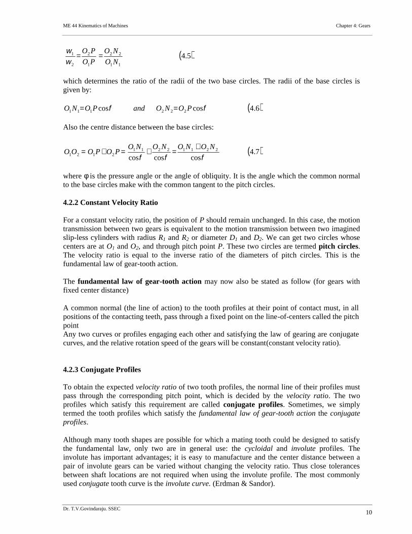
The following examples are involute spur gears. We use the word involute because the contourof gear teeth curves inward. Gears have many terminologies, parameters and principles. One ofthe important concepts is the velocity ratio, which is the ratio of the rotary velocity of the drivergear to that of the driven gears.
4.1 Generation of the Involute Curve
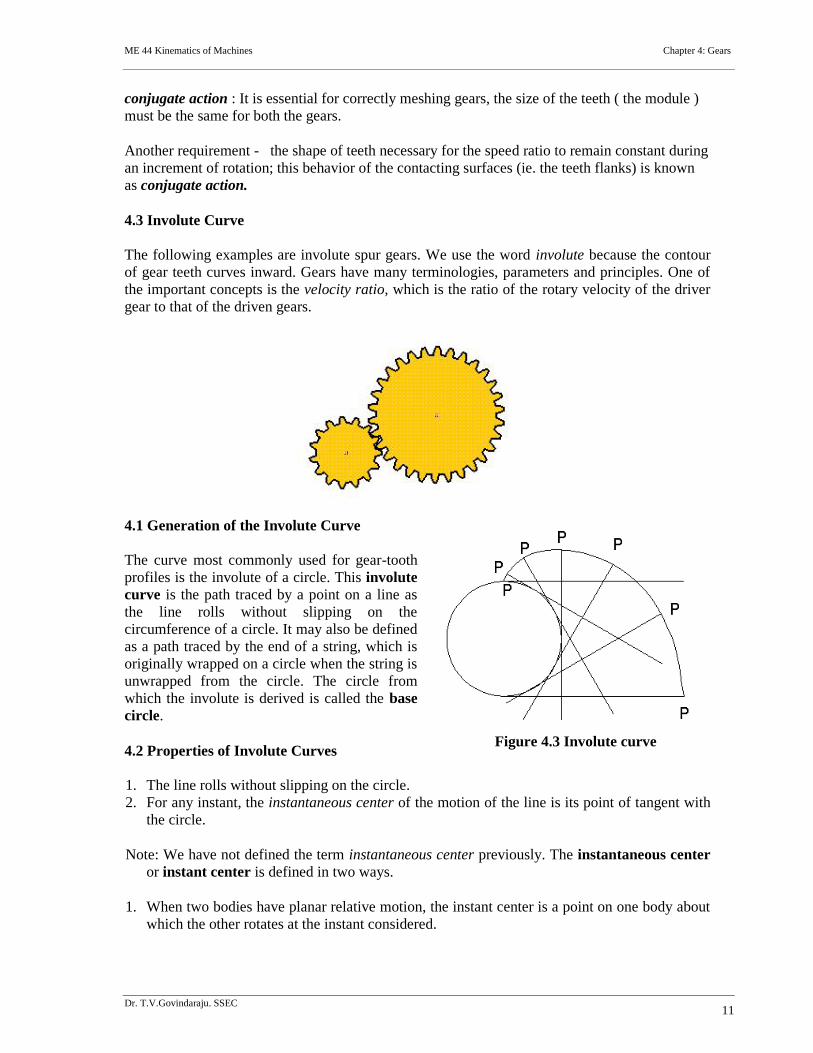
The curve most commonly used for gear-toothprofiles is the involute of a circle. This involutecurve is the path traced by a point on a line asthe line rolls without slipping on thecircumference of a circle. It may also be definedas a path traced by the end of a string, which isoriginally wrapped on a circle when the string isunwrapped from the circle. The circle fromwhich the involute is derived is called the basecircle.
4.2 Properties of Involute Curves
1. The line rolls without slipping on the circle.2. For any instant, the instantaneous center of the motion of the line is its point of tangent with
the circle.
Note: We have not defined the term instantaneous center previously. The instantaneous centeror instant center is defined in two ways.
1. When two bodies have planar relative motion, the instant center is a point on one body aboutwhich the other rotates at the instant considered.
Figure 4.3 Involute curve
ME 44 Kinematics of Machines Chapter 4: Gears
Dr. T.V.Govindaraju. SSEC12
2. When two bodies have planar relative motion, the instant center is the point at which thebodies are relatively at rest at the instant considered.
3. The normal at any point of an involute is tangent to the base circle. Because of the property(2) of the involute curve, the motion of the point that is tracing the involute is perpendicularto the line at any instant, and hence the curve traced will also be perpendicular to the line atany instant.
There is no involute curve within the base circle.
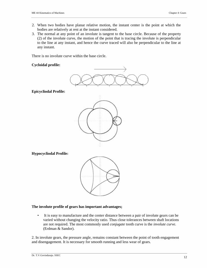
Cycloidal profile:
Epicycliodal Profile:
Hypocycliodal Profile:
The involute profile of gears has important advantages;
• It is easy to manufacture and the center distance between a pair of involute gears can bevaried without changing the velocity ratio. Thus close tolerances between shaft locationsare not required. The most commonly used conjugate tooth curve is the involute curve.(Erdman & Sandor).
2. In involute gears, the pressure angle, remains constant between the point of tooth engagementand disengagement. It is necessary for smooth running and less wear of gears.
ME 44 Kinematics of Machines Chapter 4: Gears
Dr. T.V.Govindaraju. SSEC13
But in cycloidal gears, the pressure angle is maximum at the beginning of engagement,reduces to zero at pitch point, starts increasing and again becomes maximum at the end ofengagement. This results in less smooth running of gears.
3. The face and flank of involute teeth are generated by a single curve where as in cycloidalgears, double curves (i.e. epi-cycloid and hypo-cycloid) are required for the face and flankrespectively. Thus the involute teeth are easy to manufacture than cycloidal teeth.
In involute system, the basic rack has straight teeth and the same can be cut with simple tools.
Advantages of Cycloidal gear teeth:
1. Since the cycloidal teeth have wider flanks, therefore the cycloidal gears are stronger than theinvolute gears, for the same pitch. Due to this reason, the cycloidal teeth are preferred speciallyfor cast teeth.
2. In cycloidal gears, the contact takes place between a convex flank and a concave surface,where as in involute gears the convex surfaces are in contact. This condition results in less wearin cycloidal gears as compared to involute gears. However the difference in wear is negligible
3. In cycloidal gears, the interference does not occur at all. Though there are advantages ofcycloidal gears but they are outweighed by the greater simplicity and flexibility of the involutegears.
Properties of involute teeth:
1. A normal drawn to an involute at pitch point is a tangent to the base circle.
2. Pressure angle remains constant during the mesh of an involute gears.
3. The involute tooth form of gears is insensitive to the centre distance and depends only on thedimensions of the base circle.
4. The radius of curvature of an involute is equal to the length of tangent to the base circle.
5. Basic rack for involute tooth profile has straight line form.
6. The common tangent drawn from the pitch point to the base circle of the two involutes is theline of action and also the path of contact of the involutes.
7. When two involutes gears are in mesh and rotating, they exhibit constant angular velocity ratioand is inversely proportional to the size of base circles. (Law of Gearing or conjugate action)
8. Manufacturing of gears is easy due to single curvature of profile.
ME 44 Kinematics of Machines Chapter 4: Gears
Dr. T.V.Govindaraju. SSEC14
The 14½O composite system is used for general purpose gears.
It is stronger but has no interchangeability. The tooth profile of this system has cycloidal curvesat the top and bottom and involute curve at the middle portion.
The teeth are produced by formed milling cutters or hobs.
The tooth profile of the 14½O full depth involute system was developed using gear hobs for spurand helical gears.
The tooth profile of the 20o full depth involute system may be cut by hobs.
The increase of the pressure angle from 14½o to 20o results in a stronger tooth, because the toothacting as a beam is wider at the base.
The 20o stub involute system has a strong tooth to take heavy loads.
System of Gear Teeth
The following four systems of gear teeth are commonly used in practice:
1. 14 ½O Composite system
2. 14 ½O Full depth involute system
3. 20O Full depth involute system
4. 20O Stub involute system
ME 44 Kinematics of Machines Chapter 4: Gears
Dr. T.V.Govindaraju. SSEC15
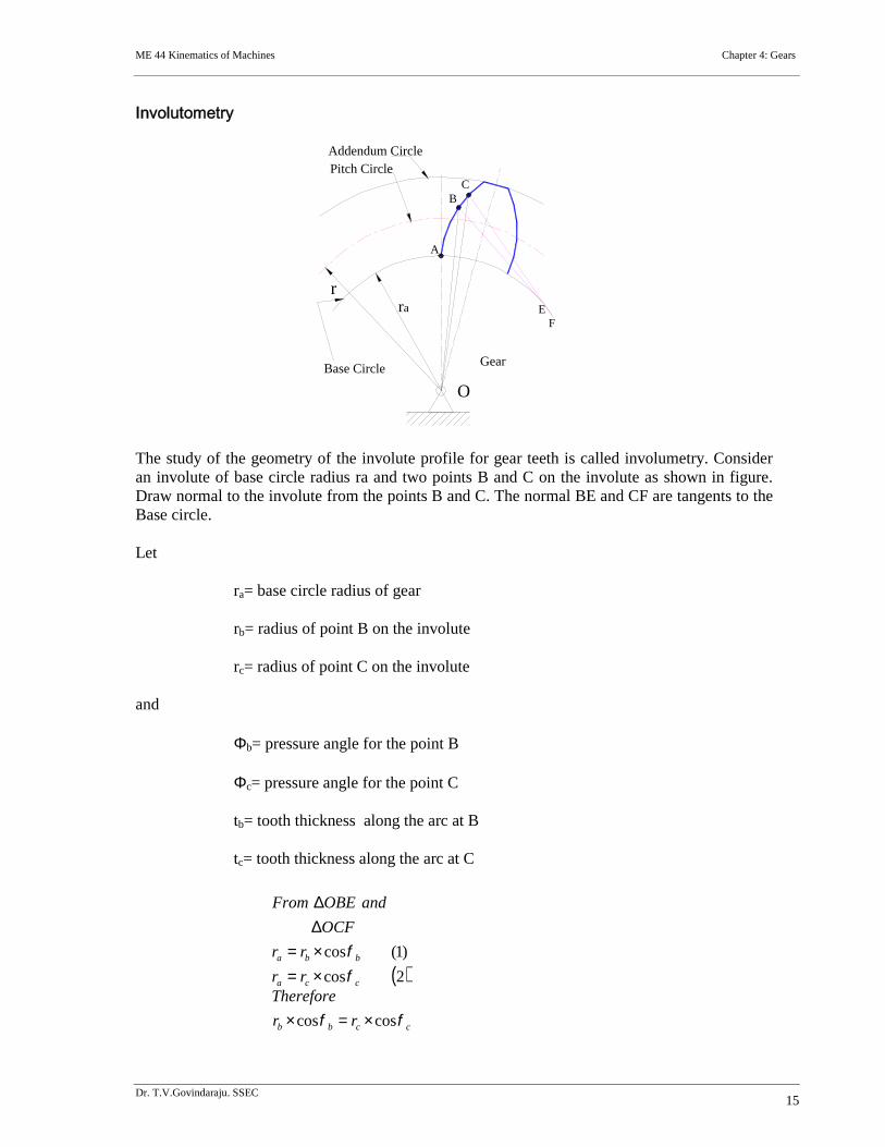
Involutometry
The study of the geometry of the involute profile for gear teeth is called involumetry. Consideran involute of base circle radius ra and two points B and C on the involute as shown in figure.Draw normal to the involute from the points B and C. The normal BE and CF are tangents to theBase circle.
Let
ra= base circle radius of gear
rb= radius of point B on the involute
rc= radius of point C on the involute
and
b= pressure angle for the point B
c= pressure angle for the point C
tb= tooth thickness along the arc at B
tc= tooth thickness along the arc at C
ra
Pitch CircleAddendum Circle
Base Circle
EF
BC
Gear
O
A
r
2cos
)1(cos
cca
bba
rr
rr
OCF
andOBEFrom
ccbb rr
Therefore
coscos
ME 44 Kinematics of Machines Chapter 4: Gears
Dr. T.V.Govindaraju. SSEC16
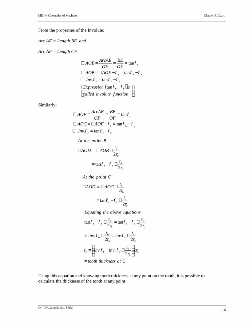
From the properties of the Involute:
Arc AE = Length BE and
Arc AF = Length CF
Similarly:
Using this equation and knowing tooth thickness at any point on the tooth, it is possible tocalculate the thickness of the tooth at any point
functioninvolutecalled
isExpression
Inv
AOEAOBOE
BE
OE
ArcAEAOE
bb
bbb
bbb
b
tan
tan.
tan
tan
ccc
CCc
c
Inv
AOFAOCOF
BE
OF
ArcAFAOF
tan.
tan
tan
b
bbb
b
b
r
t
r
tAOBAOD
BpotheAt
2tan
2
int
c
ccc
b
c
r
t
r
tAOCAOD
CpotheAt
2tan
2
int
Catthicknesstooth
rr
tinvinvt
r
tinv
r
tinv
r
t
r
t
equationsabovetheEquating
cb
bcbc
c
cc
b
bb
c
ccc
b
bbb
22
..
2.
2.
2tan
2tan
:
ME 44 Kinematics of Machines Chapter 4: Gears
Dr. T.V.Govindaraju. SSEC17
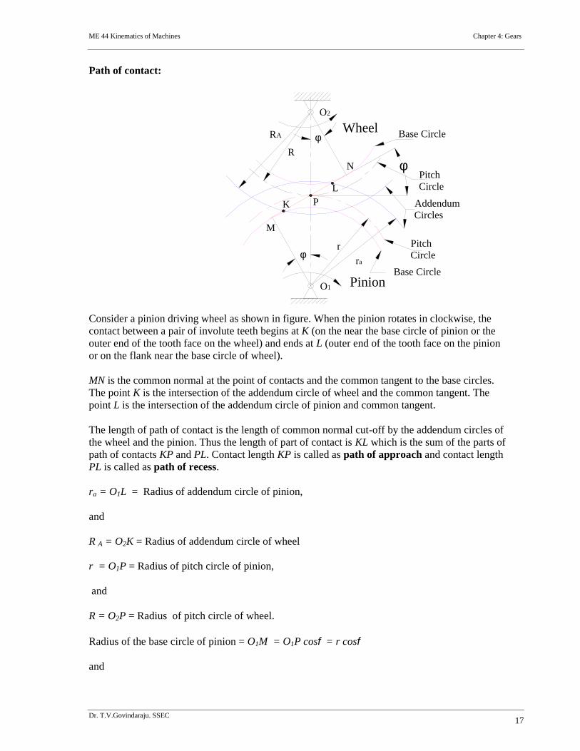
Path of contact:
Consider a pinion driving wheel as shown in figure. When the pinion rotates in clockwise, thecontact between a pair of involute teeth begins at K (on the near the base circle of pinion or theouter end of the tooth face on the wheel) and ends at L (outer end of the tooth face on the pinionor on the flank near the base circle of wheel).
MN is the common normal at the point of contacts and the common tangent to the base circles.The point K is the intersection of the addendum circle of wheel and the common tangent. Thepoint L is the intersection of the addendum circle of pinion and common tangent.
The length of path of contact is the length of common normal cut-off by the addendum circles ofthe wheel and the pinion. Thus the length of part of contact is KL which is the sum of the parts ofpath of contacts KP and PL. Contact length KP is called as path of approach and contact lengthPL is called as path of recess.
ra = O1L = Radius of addendum circle of pinion,
and
R A = O2K = Radius of addendum circle of wheel
r = O1P = Radius of pitch circle of pinion,
and
R = O2P = Radius of pitch circle of wheel.
Radius of the base circle of pinion = O1M = O1P cos = r cos
and
PitchCircle
Pinion
WheelO2
O1
P
Base Circle
Base Circle
PitchCircle
AddendumCircles
r
ra
RA
RN
K
L
M
ME 44 Kinematics of Machines Chapter 4: Gears
Dr. T.V.Govindaraju. SSEC18
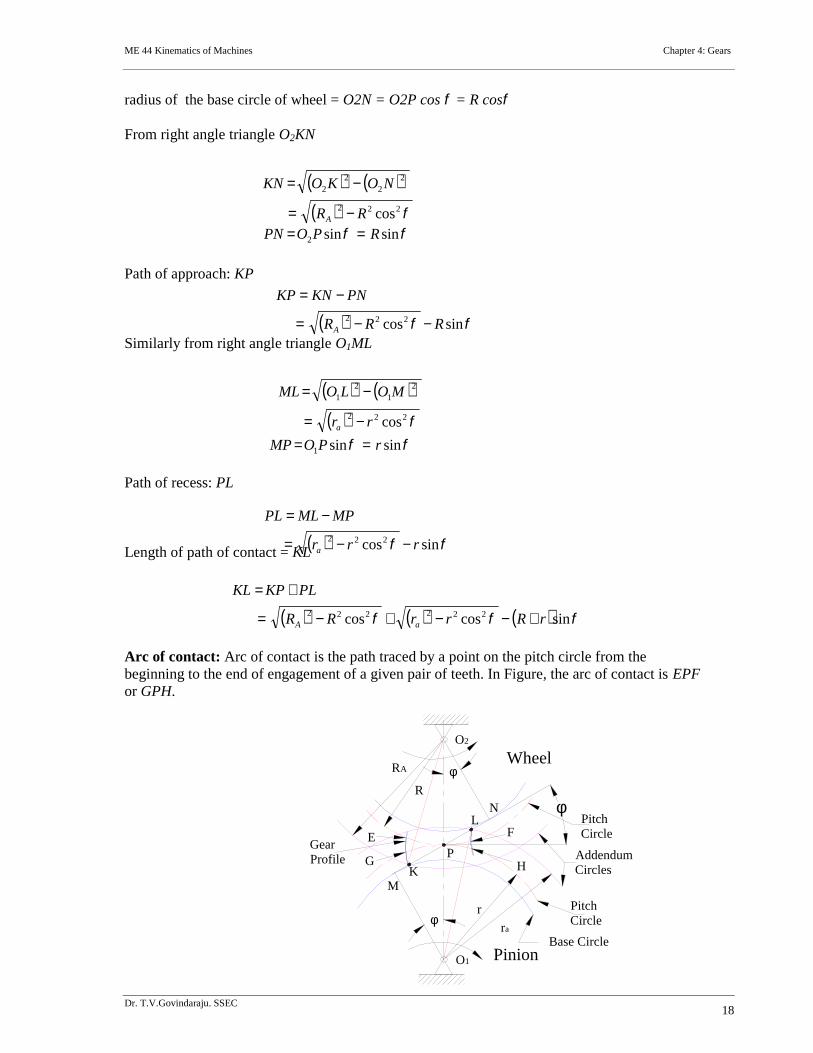
radius of the base circle of wheel = O2N = O2P cos = R cos
From right angle triangle O2KN
Path of approach: KP
Similarly from right angle triangle O1ML
Path of recess: PL
Length of path of contact = KL
Arc of contact: Arc of contact is the path traced by a point on the pitch circle from thebeginning to the end of engagement of a given pair of teeth. In Figure, the arc of contact is EPFor GPH.
222
22
22
cosRR
NOKOKN
A
sinsin2 RPOPN
sincos222 RRR
PNKNKP
A
222
21
21
cosrr
MOLOML
a
sinsin1 rPOMP
sincos222 rrr
MPMLPL
a
sincoscos 222222 rRrrRR
PLKPKL
aA
M
L
K
NR
RA
ra
r
AddendumCircles
PitchCircle
Base Circle
P
O1
O2
Wheel
Pinion
PitchCircle
H
FE
GGearProfile
ME 44 Kinematics of Machines Chapter 4: Gears
Dr. T.V.Govindaraju. SSEC19
Considering the arc of contact GPH.
The arc GP is known as arc of approach and the arc PH is called arc of recess. The anglessubtended by these arcs at O1 are called angle of approach and angle of recess respectively.
Length of arc of approach = arc GP
Length of arc of recess = arc PH
Length of arc contact = arc GPH = arc GP + arc PH
Contact Ratio (or Number of Pairs of Teeth in Contact)
The contact ratio or the number of pairs of teeth in contact is defined as the ratio of the length ofthe arc of contact to the circular pitch.
Mathematically,
Where: and m = Module.
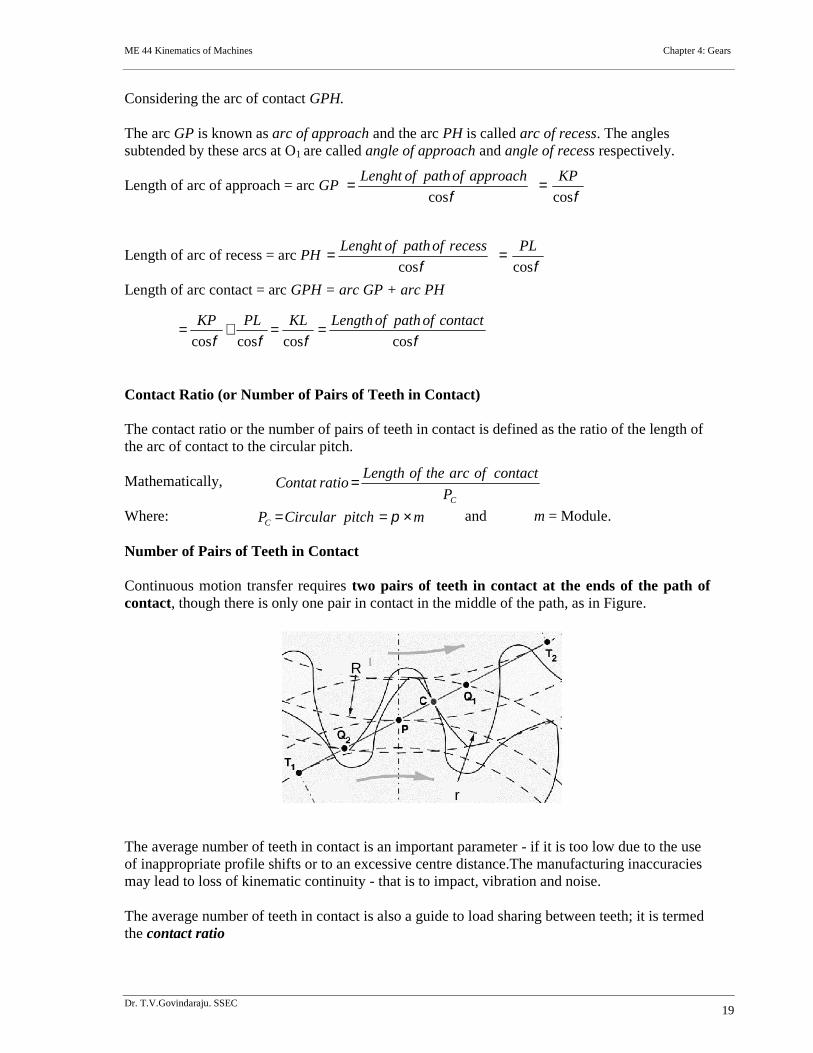
Number of Pairs of Teeth in Contact
Continuous motion transfer requires two pairs of teeth in contact at the ends of the path ofcontact, though there is only one pair in contact in the middle of the path, as in Figure.
The average number of teeth in contact is an important parameter - if it is too low due to the useof inappropriate profile shifts or to an excessive centre distance.The manufacturing inaccuraciesmay lead to loss of kinematic continuity - that is to impact, vibration and noise.
The average number of teeth in contact is also a guide to load sharing between teeth; it is termedthe contact ratio
coscos
KPapproachofpathofLenght
coscos
PLrecessofpathofLenght
coscoscoscos
contactofpathofLengthKLPLKP
CP
contactofarctheofLengthratioContat
mpitchCircularPC
R
r
ME 44 Kinematics of Machines Chapter 4: Gears
Dr. T.V.Govindaraju. SSEC20
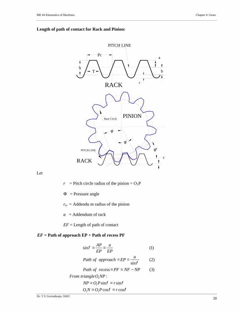
Length of path of contact for Rack and Pinion:
Let
r = Pitch circle radius of the pinion = O1P
= Pressure angle
ra. = Addendu m radius of the pinion
a = Addendum of rack
EF = Length of path of contact
EF = Path of approach EP + Path of recess PF
PITCH LINE
RACK c
T
Pca
bh
Base Circle
c
RACK
PINION
PITCH LINE
coscos
sinsin
:
)3(
)2(sin
)1(sin
11
1
1
rPONO
rPONP
NPOtriangleFrom
NPNFPFrecessofPath
aEPapproachofPath
EP
a
EP
AP
ME 44 Kinematics of Machines Chapter 4: Gears
Dr. T.V.Govindaraju. SSEC21
From triangle O1NF:
Exercise problems refer presentation slides
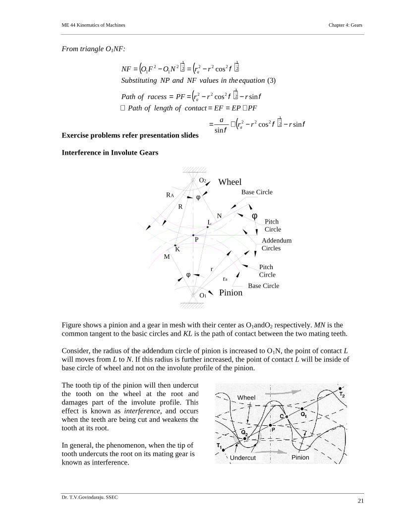
Interference in Involute Gears
Figure shows a pinion and a gear in mesh with their center as O1andO2 respectively. MN is thecommon tangent to the basic circles and KL is the path of contact between the two mating teeth.
Consider, the radius of the addendum circle of pinion is increased to O1N, the point of contact Lwill moves from L to N. If this radius is further increased, the point of contact L will be inside ofbase circle of wheel and not on the involute profile of the pinion.
The tooth tip of the pinion will then undercutthe tooth on the wheel at the root anddamages part of the involute profile. Thiseffect is known as interference, and occurswhen the teeth are being cut and weakens thetooth at its root.
In general, the phenomenon, when the tip oftooth undercuts the root on its mating gear isknown as interference.
sincossin
sincos
)3(
cos
2
1222
2
1222
2
12222
12
12
1
rrra
PFEPEFcontactoflengthofPath
rrrPFracessofPath
equationtheinvaluesNFandNPngSubstituti
rrNOFONF
a
a
a
PitchCircle
Pinion
WheelO2
O1
P
Base Circle
Base Circle
PitchCircle
AddendumCircles
r
ra
RA
RN
K
L
M
Wheel
Undercut Pinion
ME 44 Kinematics of Machines Chapter 4: Gears
Dr. T.V.Govindaraju. SSEC22
Similarly, if the radius of the addendum circles of the wheel increases beyond O2M, then the tipof tooth on wheel will cause interference with the tooth on pinion. The points M and N are calledinterference points.
Interference may be avoided if the path of the contact does not extend beyond interferencepoints. The limiting value of the radius of the addendum circle of the pinion is O1N and of thewheel is O2M.
The interference may only be prevented, if the point of contact between the two teeth is alwayson the involute profiles and if the addendum circles of the two mating gears cut the commontangent to the base circles at the points of tangency.
When interference is just prevented, the maximum length of path of contact is MN.
Methods to avoid Interference
1. Height of the teeth may be reduced.
2. Under cut of the radial flank of the pinion.
3. Centre distance may be increased. It leads to increase in pressure angle.
4. By tooth correction, the pressure angle, centre distance and base circles remain unchanged, buttooth thickness of gear will be greater than the pinion tooth thickness.
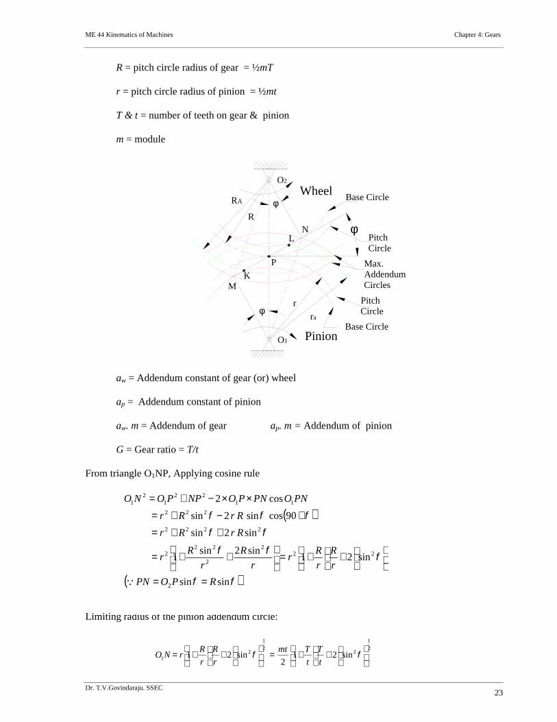
Minimum number of teeth on the pinion avoid Interference
The pinion turns clockwise and drives the gear as shown in Figure.
Points M and N are called interference points. i.e., if the contact takes place beyond M and N,interference will occur.
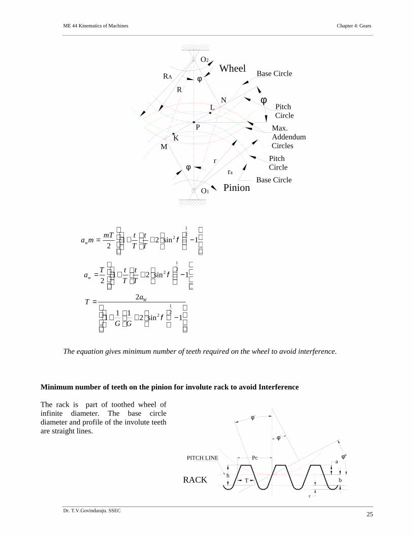
The limiting value of addendum circle radius of pinion is O1N and the limiting value ofaddendum circle radius of gear is O2M. Considering the critical addendum circle radius of gear,the limiting number of teeth on gear can be calculated.
Let
Ф = pressure angle
sinrMPapproachofpathMaximum sinRPNrecessofpathMaximum
sinRrPNMPMN
MNcontactofpathoflengthMaximum
tan
cos
sinRr
RrcontactofarcoflengthMaximum
ME 44 Kinematics of Machines Chapter 4: Gears
Dr. T.V.Govindaraju. SSEC23
R = pitch circle radius of gear = ½mT
r = pitch circle radius of pinion = ½mt
T & t = number of teeth on gear & pinion
m = module
aw = Addendum constant of gear (or) wheel
ap = Addendum constant of pinion
aw. m = Addendum of gear ap. m = Addendum of pinion
G = Gear ratio = T/t
From triangle O1NP, Applying cosine rule
Limiting radius of the pinion addendum circle:
PitchCircle
Pinion
WheelO2
O1
P
Base Circle
Base Circle
PitchCircle
Max.AddendumCircles
r
ra
RA
RN
K
L
M
sinsin
sin21sin2sin
1
sin2sin
90cossin2sin
cos2
2
222
2
222
2222
222
1122
12
1
RPOPN
r
R
r
Rr
r
R
r
Rr
RrRr
RrRr
PNOPNPONPPONO
2
1
22
1
21 sin21
2sin21
t
T
t
Tmt
r
R
r
RrNO
ME 44 Kinematics of Machines Chapter 4: Gears
Dr. T.V.Govindaraju. SSEC24
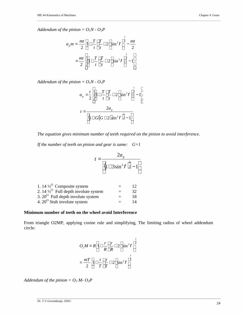
Addendum of the pinion = O1N - O1P
Addendum of the pinion = O1N - O1P
The equation gives minimum number of teeth required on the pinion to avoid interference.
If the number of teeth on pinion and gear is same: G=1
1. 14 ½O Composite system = 122. 14 ½O Full depth involute system = 323. 20O Full depth involute system = 184. 20O Stub involute system = 14
Minimum number of teeth on the wheel avoid Interference
From triangle O2MP, applying cosine rule and simplifying, The limiting radius of wheel addendumcircle:
Addendum of the pinion = O2 M- O2P
1sin212
2sin21
2
2
1
2
2
1
2
t
T
t
Tmt
mt
t
T
t
Tmtmap
1sin21
2
1sin212
2
12
2
1
2
GG
at
t
T
t
Tta
p
p
1sin31
2
2
12
pat
2
1
2
2
1
22
sin212
sin21
T
t
T
tmT
R
r
R
rRMO
ME 44 Kinematics of Machines Chapter 4: Gears
Dr. T.V.Govindaraju. SSEC25
The equation gives minimum number of teeth required on the wheel to avoid interference.
Minimum number of teeth on the pinion for involute rack to avoid Interference
The rack is part of toothed wheel ofinfinite diameter. The base circlediameter and profile of the involute teethare straight lines.
PitchCircle
Pinion
WheelO2
O1
P
Base Circle
Base Circle
PitchCircle
Max.AddendumCircles
r
ra
RA
RN
K
L
M
1sin21
2
2
1
2 T
t
T
tmTmaw
1sin21
2
2
1
2 T
t
T
tTaw
1sin211
1
2
2
1
2 GG
aT W
PITCH LINE
RACK
c
T
Pca
bh
ME 44 Kinematics of Machines Chapter 4: Gears
Dr. T.V.Govindaraju. SSEC26
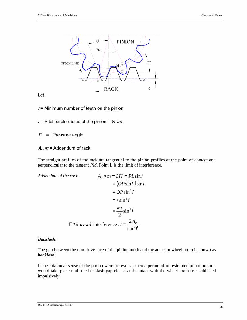
Let
t = Minimum number of teeth on the pinion
r = Pitch circle radius of the pinion = ½ mt
= Pressure angle
AR.m = Addendum of rack
The straight profiles of the rack are tangential to the pinion profiles at the point of contact andperpendicular to the tangent PM. Point L is the limit of interference.
Addendum of the rack:
Backlash:
The gap between the non-drive face of the pinion tooth and the adjacent wheel tooth is known asbacklash.
If the rotational sense of the pinion were to reverse, then a period of unrestrained pinion motionwould take place until the backlash gap closed and contact with the wheel tooth re-establishedimpulsively.
PITCH LINE
PINION
RACK
c
M
L
HP
K
2
2
2
2
sin
2:ceinterferen
sin2
sin
sin
sinsin
sin
R
R
AtavoidTo
mt
r
OP
OP
PLLHmA
ME 44 Kinematics of Machines Chapter 4: Gears
Dr. T.V.Govindaraju. SSEC27
Backlash is the error in motion that occurs when gears change direction. The term "backlash" canalso be used to refer to the size of the gap, not just the phenomenon it causes; thus, one couldspeak of a pair of gears as having, for example, "0.1 mm of backlash."
A pair of gears could be designed to have zero backlash, but this would presuppose perfection inmanufacturing, uniform thermal expansion characteristics throughout the system, and nolubricant.
Therefore, gear pairs are designed to have some backlash. It is usually provided by reducing thetooth thickness of each gear by half the desired gap distance.
In the case of a large gear and a small pinion, however, the backlash is usually taken entirely offthe gear and the pinion is given full sized teeth.
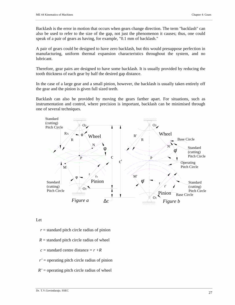
Backlash can also be provided by moving the gears farther apart. For situations, such asinstrumentation and control, where precision is important, backlash can be minimised throughone of several techniques.
Let
r = standard pitch circle radius of pinion
R = standard pitch circle radius of wheel
c = standard centre distance = r +R
r’ = operating pitch circle radius of pinion
R’ = operating pitch circle radius of wheel
M'
N'
RR'
r'r
Base Circle
Base Circle
P
O1
O2
Wheel
Pinion
M
NR
RA
rar
P
O1
O2
Wheel
Pinion
Standard(cutting)Pitch Circle
Standard(cutting)Pitch Circle
c
Standard(cutting)Pitch Circle
Standard(cutting)Pitch Circle
c
c' OperatingPitch Circle
'
'
Figure a Figure b
ME 44 Kinematics of Machines Chapter 4: Gears
Dr. T.V.Govindaraju. SSEC28
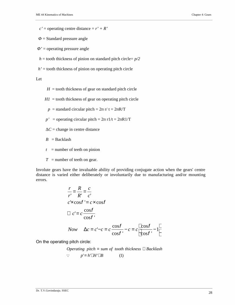
c’ = operating centre distance = r’ + R’
Ф = Standard pressure angle
Ф’ = operating pressure angle
h = tooth thickness of pinion on standard pitch circle= p/2
h’ = tooth thickness of pinion on operating pitch circle
Let
H = tooth thickness of gear on standard pitch circle
H1 = tooth thickness of gear on operating pitch circle
p = standard circular pitch = 2п r/ t = 2пR/T
p’ = operating circular pitch = 2п r1/t = 2пR1/T
∆C = change in centre distance
B = Backlash
t = number of teeth on pinion
T = number of teeth on gear.
Involute gears have the invaluable ability of providing conjugate action when the gears' centredistance is varied either deliberately or involuntarily due to manufacturing and/or mountingerrors.
On the operating pitch circle:
1'cos
cos
'cos
cos'
'cos
cos'
cos'cos''''
ccccccNow
cc
ccc
c
R
R
r
r
)1(''' BHhp
BacklashthicknesstoothofsumpitchOperating
ME 44 Kinematics of Machines Chapter 4: Gears
Dr. T.V.Govindaraju. SSEC29
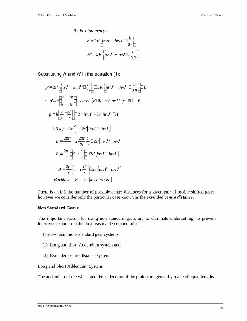
Substituting h’ and H’ in the equation (1):
There is an infinite number of possible centre distances for a given pair of profile shifted gears,however we consider only the particular case known as the extended centre distance.
Non Standard Gears:
The important reason for using non standard gears are to eliminate undercutting, to preventinterference and to maintain a reasonable contact ratio.
The two main non- standard gear systems:
(1) Long and short Addendum system and
(2) Extended centre distance system.
Long and Short Addendum System:
The addendum of the wheel and the addendum of the pinion are generally made of equal lengths.
R
hinvinvRH
r
hinvinvrh
tryinvolutomeBy
2'..'2'
2'..'2'
:
Binvcinvcc
c
c
chp
BRrinvRrinvR
R
r
rhp
BR
hinvinvR
r
hinvinvrp
'.'2.'2''
'
'''.2''.2''
'
2'..'2
2'..'2'
.'.'2'
'2
.'.'2'
2
22
'2
.'.'2'
2
invinvcc
crr
tB
invinvcc
c
t
r
t
rB
invinvcc
chpB
.'.'2
.'.'2'
'2
invinvcBBacklash
invinvcr
rrr
tB
ME 44 Kinematics of Machines Chapter 4: Gears
Dr. T.V.Govindaraju. SSEC30
Here the profile/rack cutter is advanced to a certain increment towards the gear blank and thesame quantity of increment will be withdrawn from the pinion blank.
Therefore an increased addendum for the pinion and a decreased addendum for the gear isobtained. The amount of increase in the addendum of the pinion should be exactly equal to theaddendum of the wheel is reduced.
The effect is to move the contact region from the pinion centre towards the gear centre, thusreducing approach length and increasing the recess length. In this method there is no change inpressure angle and the centre distance remains standard.
Extended centre distance system:
Reduction in interference with constant contact ratio can be obtained by increasing the centredistance. The effect of changing the centre distance is simply in increasing the pressure angle.
In this method when the pinion is being cut, the profile cutter is withdrawn a certain amountfrom the centre of the pinion so the addendum line of the cutter passes through the interferencepoint of pinion. The result is increase in tooth thickness and decrease in tooth space.
Now If the pinion is meshed with the gear, it will be found that the centre distance has beenincreased because of the decreased tooth space. Increased centre distance will have twoundesirable effects.
NOTE: Please refer presentation slides also for more figure, photos and exercise problems
References:
1. Theory of Machines and Mechanisms by Joseph Edward Shigley and John JosephUicker,Jr. McGraw-Hill International Editions.
2. Kinematics and Dynamics of Machines by George H.Martin. McGraw-HillPublications.
3. Mechanisms and Dynamics of Machinery by Hamilton H. Mabie and Fred W.Ocvirk. John Wiley and Sons.
4. Theory of Machines by V.P.Singh. Dhanpat Rai and Co.
5. The Theory of Machines through solved problems by J.S.Rao. New ageinternational publishers.
6. A text book of Theory of Machines by Dr.R.K.Bansal. Laxmi Publications (P) Ltd.
7. Internet: Many Web based e notes
Dear Staff and Students, please give the feed back to improve the contents.