keyestudio Mini Tank Robot -...
31
keyestudio www.keyestudio.cc keyestudio Mini Tank Robot Catalog 1. Introduction ................................................................................................................................... 1 2. Parameters ..................................................................................................................................... 1 3. Component list .............................................................................................................................. 1 4. Application of Arduino.................................................................................................................. 2 5. Project details .............................................................................................................................. 12 Project 1: Obstacle-avoidance Tank ........................................................................................ 12 Project 2: Bluetooth control Tank Robot................................................................................. 19 Project 3: Ultrasonic ranging Tank Robot ............................................................................... 25
Transcript of keyestudio Mini Tank Robot -...
keyestudio
www.keyestudio.cc
keyestudio Mini Tank Robot
Catalog
1. Introduction ................................................................................................................................... 1
2. Parameters ..................................................................................................................................... 1
3. Component list .............................................................................................................................. 1
4. Application of Arduino .................................................................................................................. 2
5. Project details .............................................................................................................................. 12
Project 1: Obstacle-avoidance Tank ........................................................................................ 12
Project 2: Bluetooth control Tank Robot ................................................................................. 19
Project 3: Ultrasonic ranging Tank Robot ............................................................................... 25
keyestudio
www.keyestudio.cc 1
1. Introduction
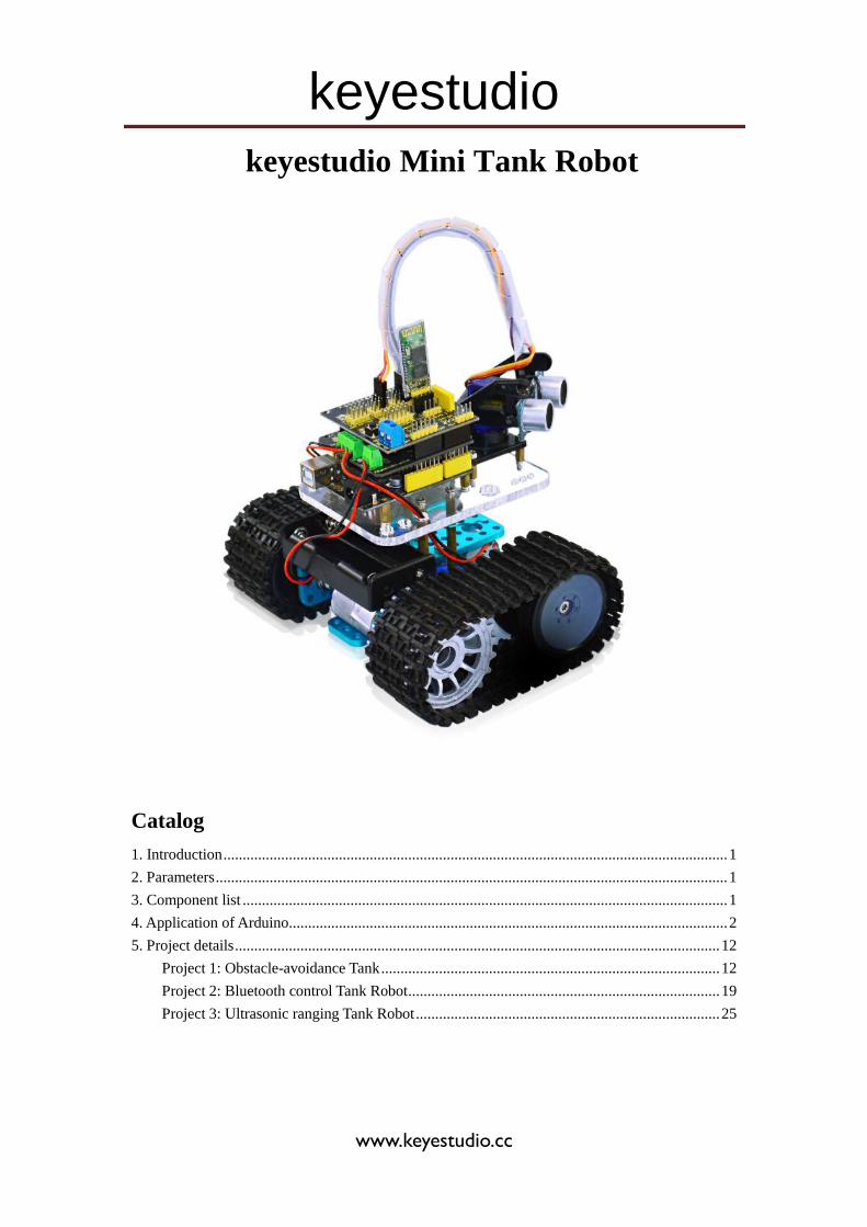
Mini tank robot is a learning application development system of microcontroller based on
Arduino. It has functions such as ultrasonic obstacle avoidance, Bluetooth remote control. This kit
contains many interesting programs. It can also be expanded with external circuit modules to have
other functions. This kit is designed to help you interestingly learn Arduino. You can learn
Arduino MCU development ability while having fun.
2. Parameters
1. Motor parameters: 6V, 150rpm/min
2. Use L298P driver module for motor control.
3. Equipped with Ultrasonic module, can detect whether there are obstacles ahead, and the
distance between the Tank robot and the obstacles to realize obstacle avoidance function.
4. Equipped with Bluetooth wireless module, can remotely control the robot after
pairing with mobile phone Bluetooth.
5. Can be connected to external 7 ~ 12V power supply; with various sensor modules,
it can realize various functions.
3. Component list
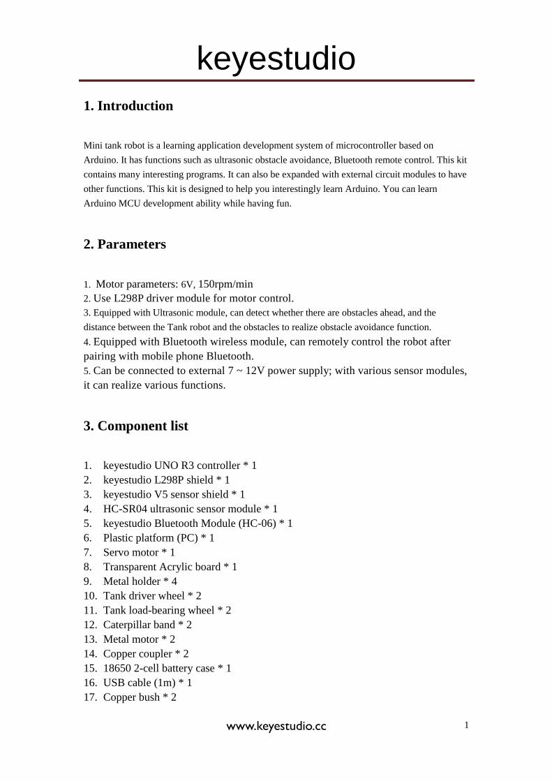
1. keyestudio UNO R3 controller * 1
2. keyestudio L298P shield * 1
3. keyestudio V5 sensor shield * 1
4. HC-SR04 ultrasonic sensor module * 1
5. keyestudio Bluetooth Module (HC-06) * 1
6. Plastic platform (PC) * 1
7. Servo motor * 1
8. Transparent Acrylic board * 1
9. Metal holder * 4
10. Tank driver wheel * 2
11. Tank load-bearing wheel * 2
12. Caterpillar band * 2
13. Metal motor * 2
14. Copper coupler * 2
15. 18650 2-cell battery case * 1
16. USB cable (1m) * 1
17. Copper bush * 2
keyestudio
www.keyestudio.cc 2
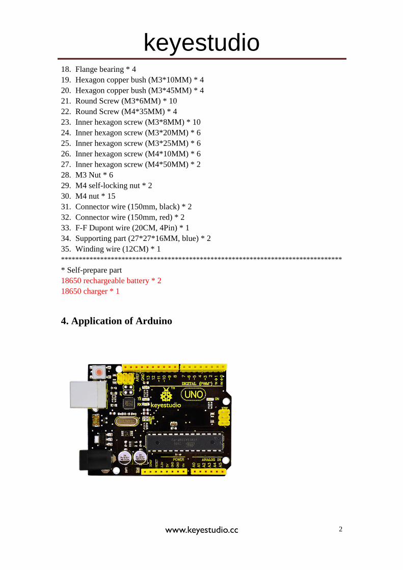
18. Flange bearing * 4
19. Hexagon copper bush (M3*10MM) * 4
20. Hexagon copper bush (M3*45MM) * 4
21. Round Screw (M3*6MM) * 10
22. Round Screw (M4*35MM) * 4
23. Inner hexagon screw (M3*8MM) * 10
24. Inner hexagon screw (M3*20MM) * 6
25. Inner hexagon screw (M3*25MM) * 6
26. Inner hexagon screw (M4*10MM) * 6
27. Inner hexagon screw (M4*50MM) * 2
28. M3 Nut * 6
29. M4 self-locking nut * 2
30. M4 nut * 15
31. Connector wire (150mm, black) * 2
32. Connector wire (150mm, red) * 2
33. F-F Dupont wire (20CM, 4Pin) * 1
34. Supporting part (27*27*16MM, blue) * 2
35. Winding wire (12CM) * 1
*******************************************************************************
* Self-prepare part
18650 rechargeable battery * 2
18650 charger * 1
4. Application of Arduino
keyestudio
www.keyestudio.cc 3
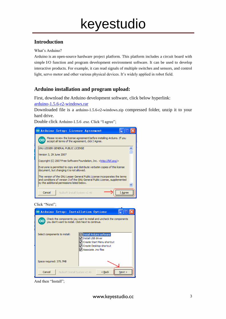
Introduction
What’s Arduino?
Arduino is an open-source hardware project platform. This platform includes a circuit board with
simple I/O function and program development environment software. It can be used to develop
interactive products. For example, it can read signals of multiple switches and sensors, and control
light, servo motor and other various physical devices. It’s widely applied in robot field.
Arduino installation and program upload:
First, download the Arduino development software, click below hyperlink:
arduino-1.5.6-r2-windows.rar
Downloaded file is a arduino-1.5.6-r2-windows.zip compressed folder, unzip it to your
hard drive.
Double click Arduino-1.5.6 .exe. Click “I agree”;
Click “Next”;
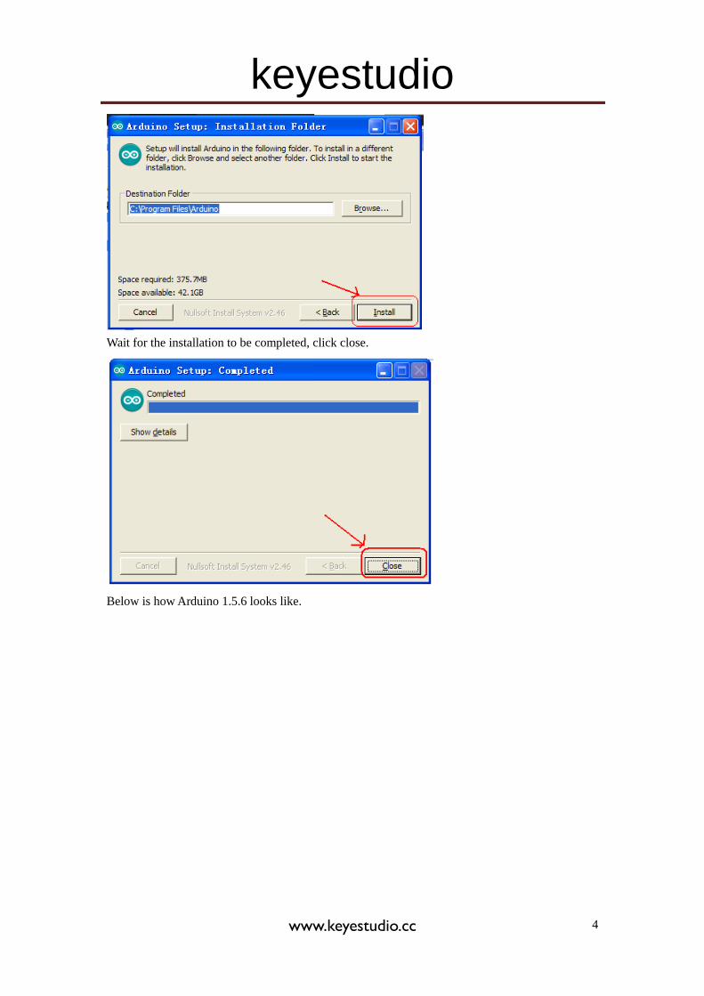
And then “Install”;
keyestudio
www.keyestudio.cc 4
Wait for the installation to be completed, click close.
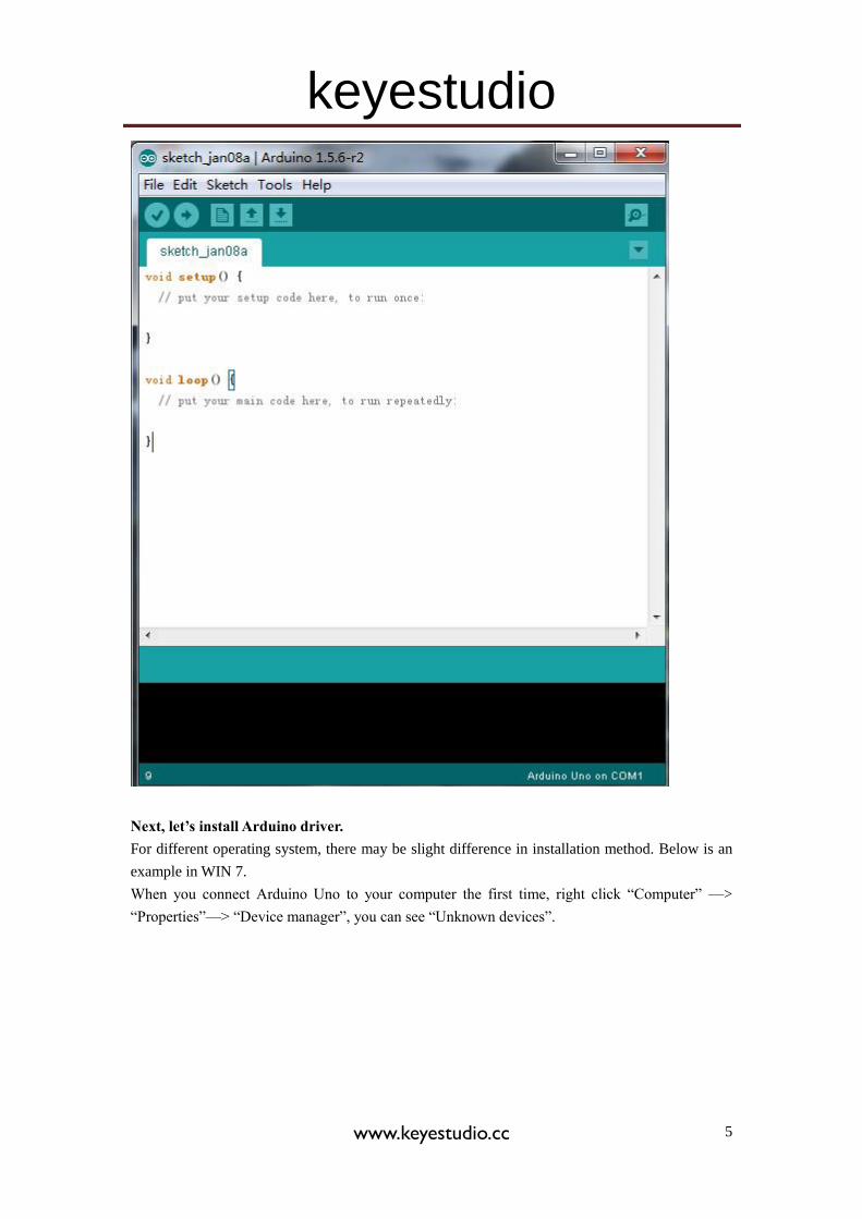
Below is how Arduino 1.5.6 looks like.
keyestudio
www.keyestudio.cc 5
Next, let’s install Arduino driver.
For different operating system, there may be slight difference in installation method. Below is an
example in WIN 7.
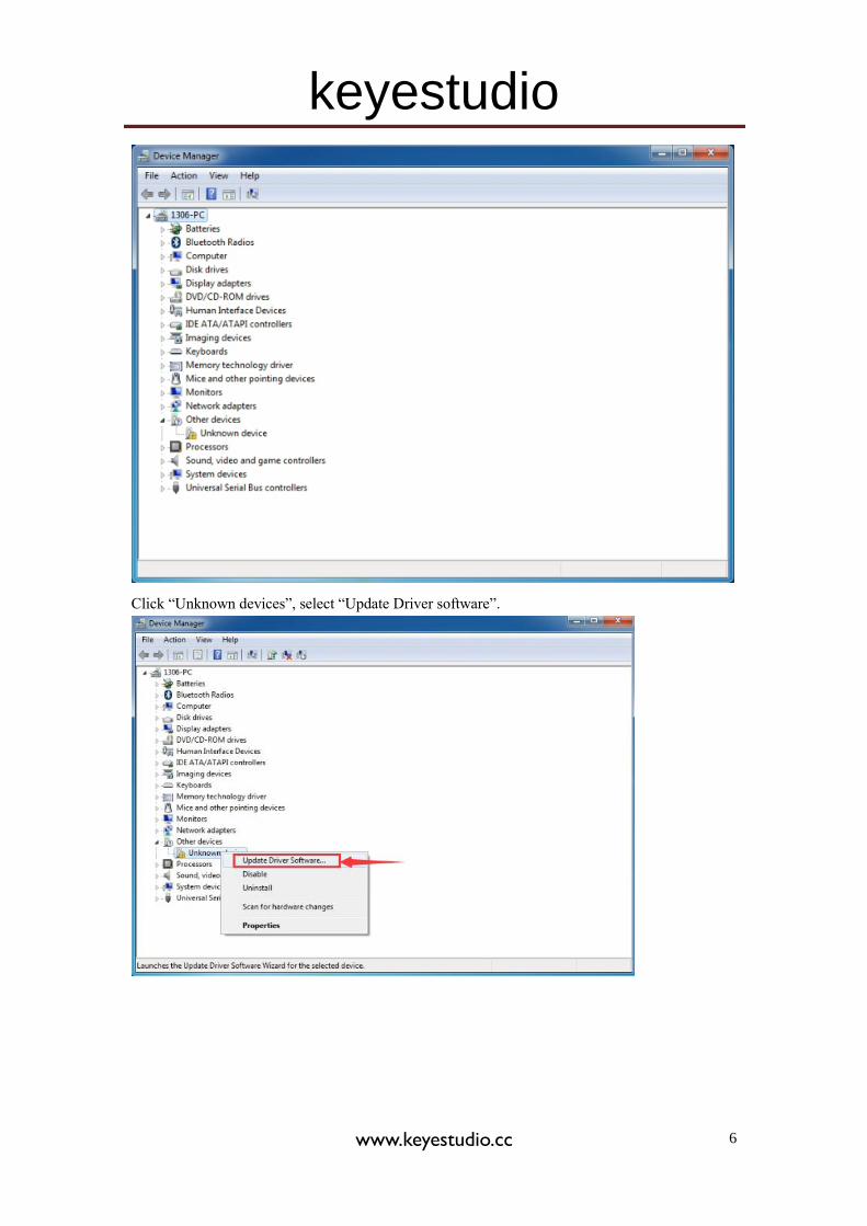
When you connect Arduino Uno to your computer the first time, right click “Computer” —>
“Properties”—> “Device manager”, you can see “Unknown devices”.
keyestudio
www.keyestudio.cc 6
Click “Unknown devices”, select “Update Driver software”.
keyestudio
www.keyestudio.cc 7
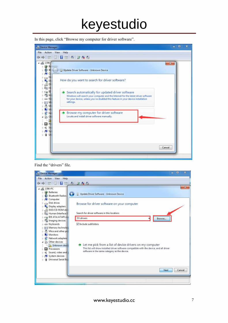
In this page, click “Browse my computer for driver software”.
Find the “drivers” file.
keyestudio
www.keyestudio.cc 8
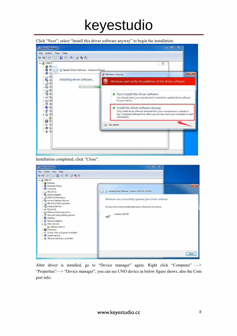
Click “Next”; select “Install this driver software anyway” to begin the installation.
Installation completed; click “Close”.
After driver is installed, go to “Device manager” again. Right click “Computer” —>
“Properties”—> “Device manager”, you can see UNO device as below figure shows, also the Com
port info.
keyestudio
www.keyestudio.cc 9
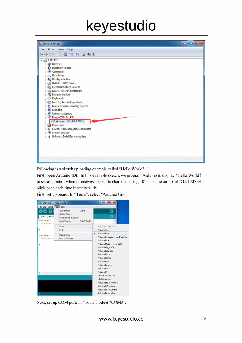
Following is a sketch uploading example called “Hello World!”.
First, open Arduino IDE. In this example sketch, we program Arduino to display “Hello World!”
in serial monitor when it receives a specific character string “R”; also the on-board D13 LED will
blink once each time it receives “R”.
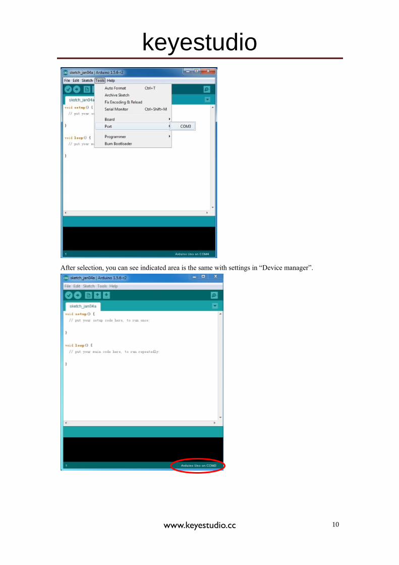
First, set up board; In “Tools”, select “Arduino Uno”.
Next, set up COM port; In “Tools”, select “COM3”.
keyestudio
www.keyestudio.cc 10
After selection, you can see indicated area is the same with settings in “Device manager”.
keyestudio
www.keyestudio.cc 11
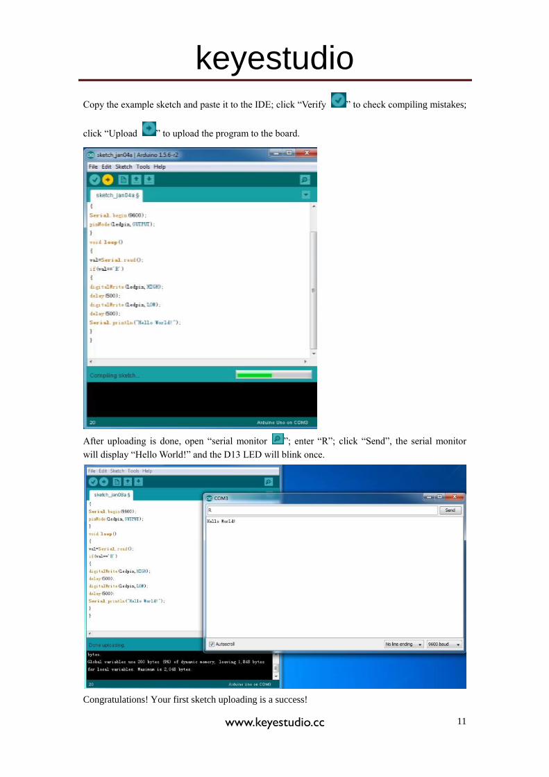
Copy the example sketch and paste it to the IDE; click “Verify ” to check compiling mistakes;
click “Upload ” to upload the program to the board.
After uploading is done, open “serial monitor ”; enter “R”; click “Send”, the serial monitor
will display “Hello World!” and the D13 LED will blink once.
Congratulations! Your first sketch uploading is a success!
keyestudio
www.keyestudio.cc 12
5. Project details
Project 1: Obstacle-avoidance Tank
Introduction
This project is a simple obstacle avoidance tank robot system based on Arduino, including the
software and hardware design. The controller part is a UNO board. Ultrasonic sensor and servo
motors are used to detect whether there are obstacles ahead, and feedback the signal to UNO.
UNO will analyze the signal to determine and control the motors movement to adjust Tank
moving direction. Therefore the tank robot can automatically avoid obstacles.
Working principle
1. Ultrasonic ranging: the controller sends out a a high level signal of more than 10μs, when the
output pin receives the high level signal, the timer will be on; when the signal changes to low level,
we can read the time period of the timer, which is the time used for this ultrasonic wave
transceiving. Together with its transmission speed, we can calculate the distance.
2. After we use the ultrasonic sensor to detect the distance from an obstacle, we can control the
movement of the Tank according to the data.
3. If the distance from the obstacle is < 10cm, the Tank moves backward; if the distance
is >=25cm, the Tank moves forward; if the distance is <25cm, we control the movement of the
servo motors to measure the distance of the left and right. If both the distance are <10cm, the Tank
moves backward; if the distance are both >= 10cm, and distance on the left is more than the
distance on the right, the Tank moves to the left; if distance on the left is <= the distance on the
right, the Tank moves to the right.
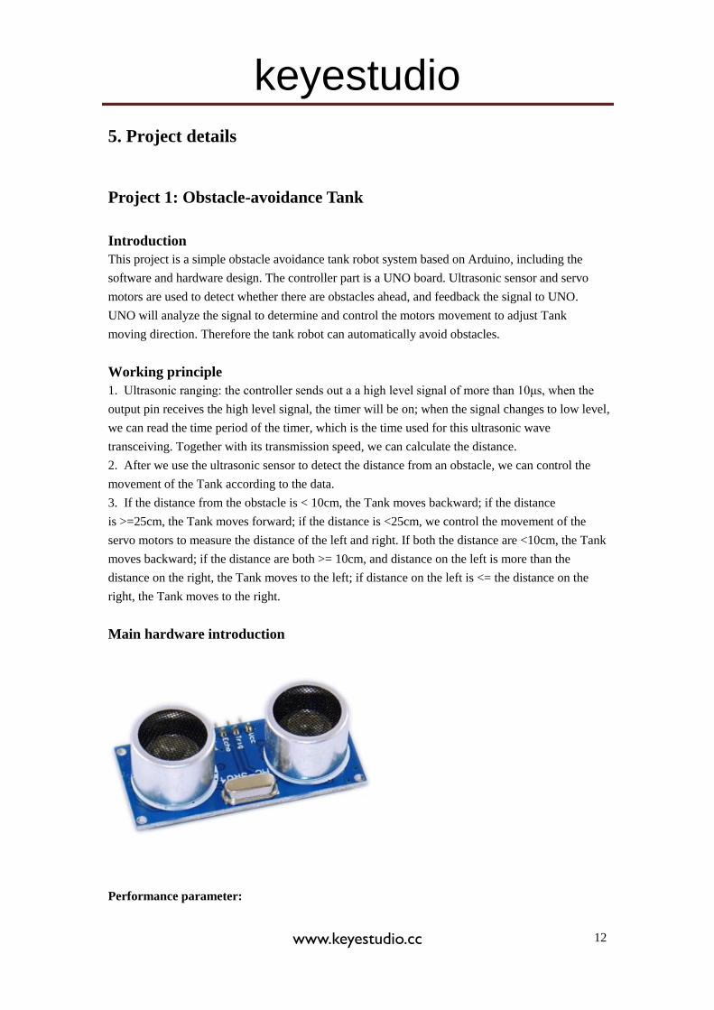
Main hardware introduction
Performance parameter:
keyestudio
www.keyestudio.cc 13
1. Working voltage: DC5V
2. Static Current: <2mA
3. Level output: high 5V
4. Level output: low 0V
5. Induction angle: <15°
6. Detecting range : 2cm-450cm
7. Detecting accuracy: 0.3cm
Detecting principle
(1) use IO port to trigger the ranging, with at least 10μs high level signal;
(2) the module automatically sends 8 40khz square waves and automatically detect whether there
is returned waves;
(3) if there is signal returned, the IO port will output a low level signal. The lasting time of the
high level signal is the time between the launching and receiving of the ultrasonic signal. The
detecting range= (high level lasting time*speed of sound(340M/S))/2 。
Usage:
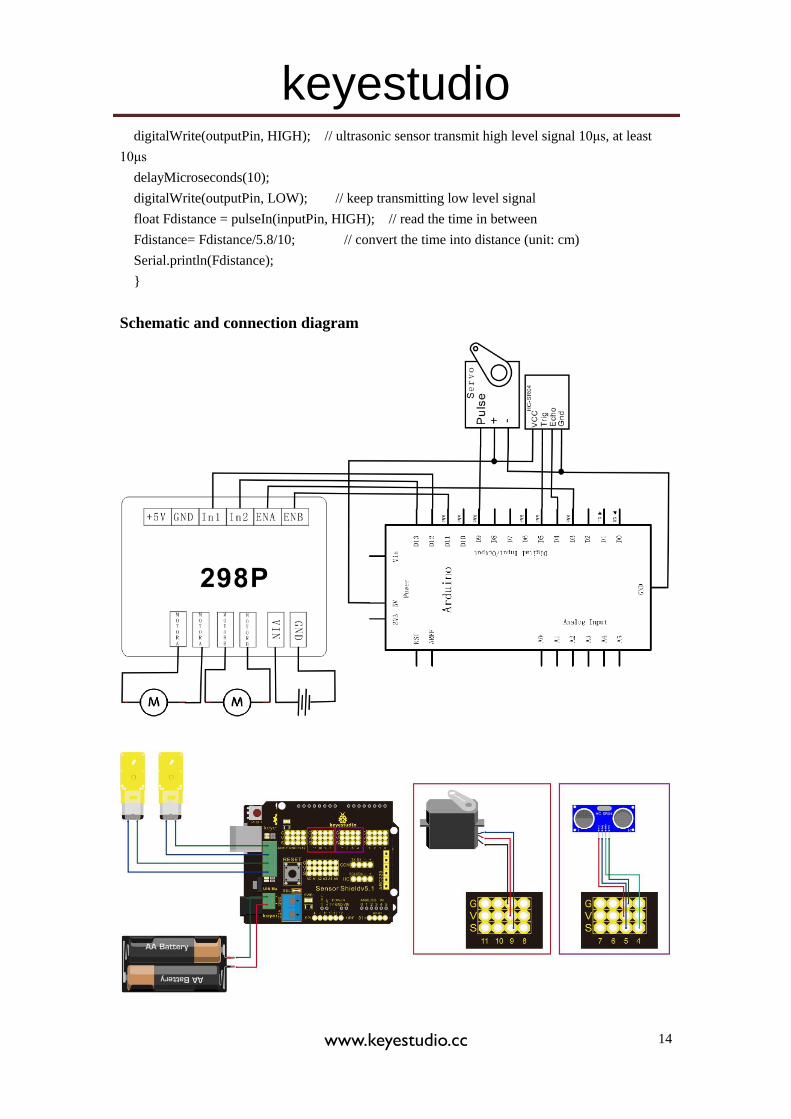
1. The sensor has 4 pins, Vcc, Trig, Echo, and Gnd. Vcc and Gnd is for power supply, Trig as
signal transmitting end (connect to D5), Echo as signal receiving end (connect to D4).
2. Open serial monitor; set baud rate to 9600; we can see the distance value from the obstacle in
cm.
Module test program:
int inputPin = 4; // set Echo pin to D4
int outputPin =5; // set Trig pin to D4
void setup()
{
Serial.begin(9600);
pinMode(inputPin, INPUT); // define sensor pin as input
pinMode(outputPin, OUTPUT); // define sensor pin as output
}
void loop()
{
digitalWrite(outputPin, LOW); // ultrasonic sensor transmit low level signal 2μs
delayMicroseconds(2);
keyestudio
www.keyestudio.cc 14
digitalWrite(outputPin, HIGH); // ultrasonic sensor transmit high level signal 10μs, at least
10μs
delayMicroseconds(10);
digitalWrite(outputPin, LOW); // keep transmitting low level signal
float Fdistance = pulseIn(inputPin, HIGH); // read the time in between
Fdistance= Fdistance/5.8/10; // convert the time into distance (unit: cm)
Serial.println(Fdistance);
}
Schematic and connection diagram
keyestudio
www.keyestudio.cc 15
Obstacle avoidance Tank Robot program
/*
L = Left
R = Right
F = forward
B = backward
*/
#include <Servo.h>
int pinLB = 12; // define pin 12
int pinLF = 3; // define pin 3
int pinRB = 13; // define pin 13
int pinRF = 11; // define pin 11
////////////////////////////////
int inputPin = 4; // define pin for sensor echo
int outputPin =5; // define pin for sensor trig
int Fspeedd = 0; // forward speed
int Rspeedd = 0; // right speed
int Lspeedd = 0; // left speed
int directionn = 0; // forward=8 backward=2 left=4 right=6
Servo myservo; // set myservo
int delay_time = 250; // settling time after steering servo motor moving B
int Fgo = 8; // Move F
int Rgo = 6; // move to the R
int Lgo = 4; // move to the L
int Bgo = 2; // move B
void setup()
{
Serial.begin(9600); // Define motor output pin
pinMode(pinLB,OUTPUT); // pin 12
pinMode(pinLF,OUTPUT); // pin 3 (PWM)
pinMode(pinRB,OUTPUT); // pin 13
pinMode(pinRF,OUTPUT); // pin 11 (PWM)
pinMode(inputPin, INPUT); // define input pin for sensor
pinMode(outputPin, OUTPUT); // define output pin for sensor
myservo.attach(9); // Define servo motor output pin to D9 (PWM)
}
void advance() // move forward
{
digitalWrite(pinLB,LOW); // right wheel moves forward
digitalWrite(pinRB, LOW); // left wheel moves forward
analogWrite(pinLF,255);
keyestudio
www.keyestudio.cc 16
analogWrite(pinRF,255);
}
void stopp() // stop
{
digitalWrite(pinLB,HIGH);
digitalWrite(pinRB,HIGH);
analogWrite(pinLF,0);
analogWrite(pinRF,0);
}
void right() // turn right (single wheel)
{
digitalWrite(pinLB,HIGH); // wheel on the left moves forward
digitalWrite(pinRB,LOW); // wheel on the right moves backward
analogWrite(pinLF, 255);
analogWrite(pinRF,255);
}
void left() // turn left (single wheel)
{
digitalWrite(pinLB,LOW); // wheel on the left moves backward
digitalWrite(pinRB,HIGH); // wheel on the right moves forward
analogWrite(pinLF, 255);
analogWrite(pinRF,255);
}
void back() // move backward
{
digitalWrite(pinLB,HIGH); // motor moves to left rear
digitalWrite(pinRB,HIGH); // motor moves to right rear
analogWrite(pinLF,255);
analogWrite(pinRF,255);
}
void detection() // measure 3 angles (0.90.179)
{
int delay_time = 250; // stabilizing time for servo motor after moving backward
ask_pin_F(); // read the distance ahead
if(Fspeedd < 10) // if distance ahead is <10cm
{
stopp(); // clear data
delay(100);
back(); // move backward for 0.2S
delay(200);
}
keyestudio
www.keyestudio.cc 17
if(Fspeedd < 25) // if distance ahead is <25cm
{
stopp();
delay(100); // clear data
ask_pin_L(); // read distance on the left
delay(delay_time); // stabilizing time for servo motor
ask_pin_R(); // read distance on the right
delay(delay_time); // stabilizing time for servo motor
if(Lspeedd > Rspeedd) // if distance on the left is >distance on the right
{
directionn = Lgo; // move to the L
}
if(Lspeedd <= Rspeedd) // if distance on the left is <= distance on the right
{
directionn = Rgo; // move to the right
}
if (Lspeedd < 10 && Rspeedd < 10) // if distance on left and right are both <10cm
{
directionn = Bgo; // move backward
}
}
else // if distance ahead is >25cm
{
directionn = Fgo; // move forward
}
}
void ask_pin_F() // measure the distance ahead
{
myservo.write(90);
digitalWrite(outputPin, LOW); // ultrasonic sensor transmit low level signal 2μs
delayMicroseconds(2);
digitalWrite(outputPin, HIGH); // ultrasonic sensor transmit high level signal10μs, at
least 10μs
delayMicroseconds(10);
digitalWrite(outputPin, LOW); // keep transmitting low level signal
float Fdistance = pulseIn(inputPin, HIGH); // read the time in between
Fdistance= Fdistance/5.8/10; // convert time into distance (unit: cm)
Fspeedd = Fdistance; // read the distance into Fspeedd
}
keyestudio
www.keyestudio.cc 18
void ask_pin_L() // measure distance on the left
{
myservo.write(5);
delay(delay_time);
digitalWrite(outputPin, LOW); // ultrasonic sensor transmit low level signal 2μs
delayMicroseconds(2);
digitalWrite(outputPin, HIGH); // ultrasonic sensor transmit high level signal10μs, at
least 10μs
delayMicroseconds(10);
digitalWrite(outputPin, LOW); // keep transmitting low level signal
float Ldistance = pulseIn(inputPin, HIGH); // read the time in between
Ldistance= Ldistance/5.8/10; // convert time into distance (unit: cm)
Lspeedd = Ldistance; // read the distance into Lspeedd
}
void ask_pin_R() // measure distance on the right
{
myservo.write(177);
delay(delay_time);
digitalWrite(outputPin, LOW); // ultrasonic sensor transmit low level signal 2μs
delayMicroseconds(2);
digitalWrite(outputPin, HIGH); // ultrasonic sensor transmit high level signal10μs, at
least 10μs
delayMicroseconds(10);
digitalWrite(outputPin, LOW); // keep transmitting low level signal
float Rdistance = pulseIn(inputPin, HIGH); // read the time in between
Rdistance= Rdistance/5.8/10; // convert time into distance (unit: cm)
Rspeedd = Rdistance; // read the distance into Rspeedd
}
void loop()
{
myservo.write(90); // home set the servo motor, ready for next measurement
detection(); // measure the angle and determine which direction to move
if(directionn == 2) // if directionn= 2
{
back();
delay(800); // go backward
left() ;
delay(200); // Move slightly to the left (to prevent stuck in dead end)
}
if(directionn == 6) // if directionn = 6
{
back();
keyestudio
www.keyestudio.cc 19
delay(100);
right();
delay(600); // turn right
}
if(directionn == 4) // if directionn = 4
{
back();
delay(600);
left();
delay(600); // turn left
}
if(directionn == 8) // if directionn = 8
{
advance(); // move forward
delay(100);
}
}
Project 2: Bluetooth control Tank Robot
Introduction
This project is a tank robot system based on Bluetooth communication, including software and
hardware design. The controller part is a UNO board. A Bluetooth module is used to receive the
Bluetooth signal from the cellphone and feedback the signal to the UNO. UNO will analyze the
signal to determine and control the motors movement to adjust car moving direction. Therefore
the tank robot can be controlled by cellphone.
Working principle
1. The Bluetooth module is connected to UNO; the module communicates with cell phone through
a Bluetooth APP.
2. The Bluetooth APP on the cell phone will pass information of “U”“D”“L”“R”“S” to the
Bluetooth module.
3. The Bluetooth module will pass the information to the UNO, so the UNO can determine car
movement according to the information received.
4. When the UNO receives a “U”, the car goes straight forward; when it receives a “D”, the car
goes backward; “L” for turning left; “R” for turning right; and “S” for stop.
Main hardware introduction
keyestudio
www.keyestudio.cc 20
Bluetooth communication:
The term “Bluetooth” is derived from a Denmark king’s name in 10th century. The king is named
Harald Blatand, while “Blatand” in English means Bluetooth.
The so-called Bluetooth technology is actually a type of short distance wireless transmission
technology. We can use “Bluetooth” to effectively simplify the communication between terminal
devices such as laptop and mobile phone. It can also simplify communication between these
devices and the Internet, thus improving the speed and efficiency of data transmission between
them, widening the application scope of wireless communication.
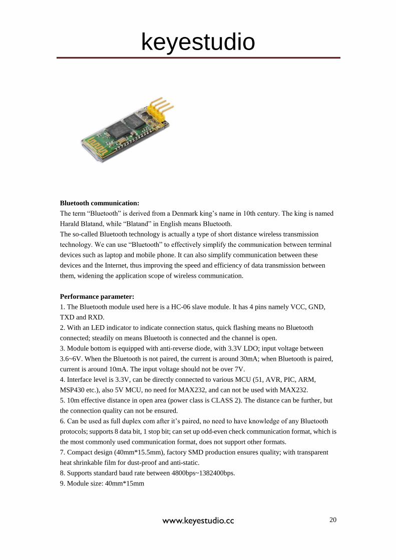
Performance parameter:
1. The Bluetooth module used here is a HC-06 slave module. It has 4 pins namely VCC, GND,
TXD and RXD.
2. With an LED indicator to indicate connection status, quick flashing means no Bluetooth
connected; steadily on means Bluetooth is connected and the channel is open.
3. Module bottom is equipped with anti-reverse diode, with 3.3V LDO; input voltage between
3.6~6V. When the Bluetooth is not paired, the current is around 30mA; when Bluetooth is paired,
current is around 10mA. The input voltage should not be over 7V.
4. Interface level is 3.3V, can be directly connected to various MCU (51, AVR, PIC, ARM,
MSP430 etc.), also 5V MCU, no need for MAX232, and can not be used with MAX232.
5. 10m effective distance in open area (power class is CLASS 2). The distance can be further, but
the connection quality can not be ensured.
6. Can be used as full duplex com after it’s paired, no need to have knowledge of any Bluetooth
protocols; supports 8 data bit, 1 stop bit; can set up odd-even check communication format, which is
the most commonly used communication format, does not support other formats.
7. Compact design (40mm*15.5mm), factory SMD production ensures quality; with transparent
heat shrinkable film for dust-proof and anti-static.
8. Supports standard baud rate between 4800bps~1382400bps.
9. Module size: 40mm*15mm
keyestudio
www.keyestudio.cc 21
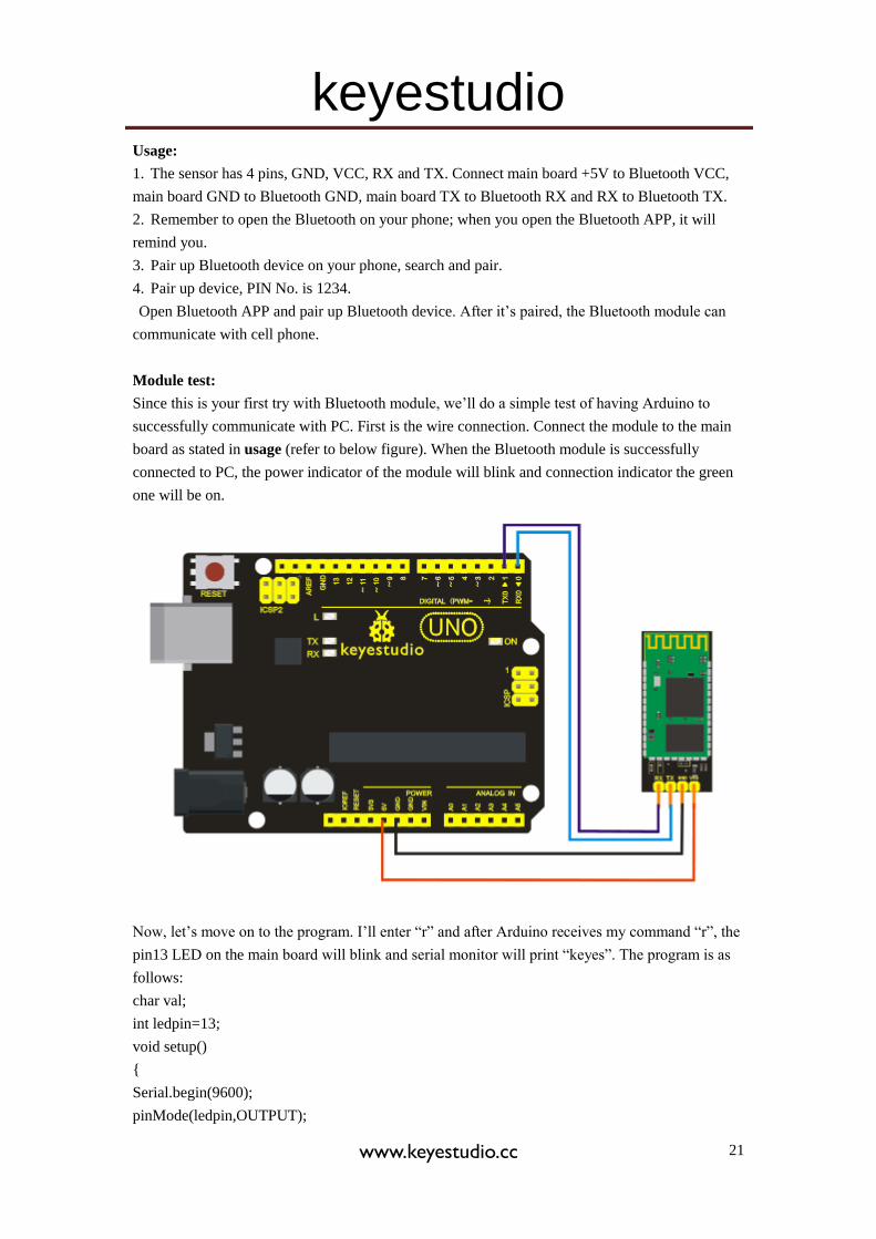
Usage:
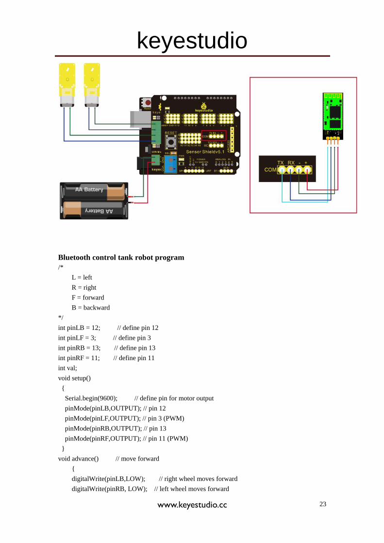
1. The sensor has 4 pins, GND, VCC, RX and TX. Connect main board +5V to Bluetooth VCC,
main board GND to Bluetooth GND, main board TX to Bluetooth RX and RX to Bluetooth TX.
2. Remember to open the Bluetooth on your phone; when you open the Bluetooth APP, it will
remind you.
3. Pair up Bluetooth device on your phone, search and pair.
4. Pair up device, PIN No. is 1234.
Open Bluetooth APP and pair up Bluetooth device. After it’s paired, the Bluetooth module can
communicate with cell phone.
Module test:
Since this is your first try with Bluetooth module, we’ll do a simple test of having Arduino to
successfully communicate with PC. First is the wire connection. Connect the module to the main
board as stated in usage (refer to below figure). When the Bluetooth module is successfully
connected to PC, the power indicator of the module will blink and connection indicator the green
one will be on.
Now, let’s move on to the program. I’ll enter “r” and after Arduino receives my command “r”, the
pin13 LED on the main board will blink and serial monitor will print “keyes”. The program is as
follows:
char val;
int ledpin=13;
void setup()
{
Serial.begin(9600);
pinMode(ledpin,OUTPUT);
keyestudio
www.keyestudio.cc 22
}
void loop()
{
val=Serial.read();
if(val=='r')
{
digitalWrite(ledpin,HIGH);
delay((500);
digitalWrite(ledpin,LOW);
delay(500);
Serial.println("keyes");
}
}
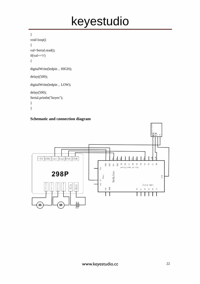
Schematic and connection diagram
keyestudio
www.keyestudio.cc 23
Bluetooth control tank robot program
/*
L = left
R = right
F = forward
B = backward
*/
int pinLB = 12; // define pin 12
int pinLF = 3; // define pin 3
int pinRB = 13; // define pin 13
int pinRF = 11; // define pin 11
int val;
void setup()
{
Serial.begin(9600); // define pin for motor output
pinMode(pinLB,OUTPUT); // pin 12
pinMode(pinLF,OUTPUT); // pin 3 (PWM)
pinMode(pinRB,OUTPUT); // pin 13
pinMode(pinRF,OUTPUT); // pin 11 (PWM)
}
void advance() // move forward
{
digitalWrite(pinLB,LOW); // right wheel moves forward
digitalWrite(pinRB, LOW); // left wheel moves forward
keyestudio
www.keyestudio.cc 24
analogWrite(pinLF,255);
analogWrite(pinRF,255);
}
void stopp() // stop
{
digitalWrite(pinLB,HIGH);
digitalWrite(pinRB,HIGH);
analogWrite(pinLF,0);
analogWrite(pinRF,0);
}
void right() // turn right (single wheel)
{
digitalWrite(pinLB,HIGH); // left wheel moves forward
digitalWrite(pinRB,LOW); // right wheel moves backward
analogWrite(pinLF, 255);
analogWrite(pinRF,255);
}
void left() // turn left (single wheel)
{
digitalWrite(pinLB,LOW); // left wheel moves forward
digitalWrite(pinRB,HIGH); // right wheel moves backward
analogWrite(pinLF, 255);
analogWrite(pinRF,255);
}
void back() // move backward
{
digitalWrite(pinLB,HIGH); // motor moves to left rear
digitalWrite(pinRB,HIGH); // motor moves to right rear
analogWrite(pinLF,255);
analogWrite(pinRF,255);
}
void loop()
{
val=Serial.read();
if(val=='U')advance();
if(val=='D')back();
if(val=='L')left() ;
if(val=='R')right();
if(val=='S')stopp();
}
keyestudio
www.keyestudio.cc 25
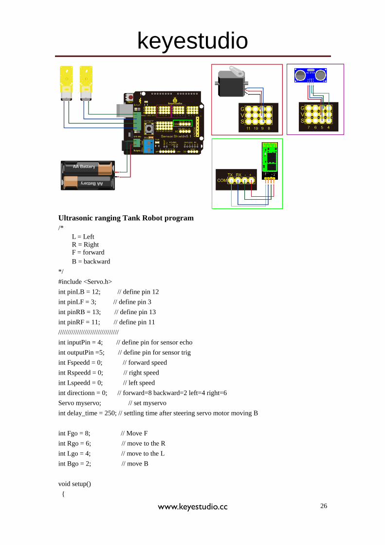
Project 3: Ultrasonic ranging Tank Robot
Introduction
In project 1, we use the ultrasonic sensor module for the tank to realize obstacle
avoidance function. In project 2, we use a HC-06 Bluetooth module for the tank, so the tank
can be controlled form a cellphone terminal.
This project is based on project 1 and project 2. Here, we apply echo sounding method for the
ranging. The trig end of ultrasonic sensor will launch ultrasonic wave in a specific direction. At
the same time, the timer begins to count; when the ultrasonic wave encounters an obstacle, it’s
reflected back; when the echo end receives the signal, the timer stops the count. With the traveling
speed of the wave and the traveling time, we can calculate the distance between the launching
point and the obstacle.
Also,we will use the HC-06 Bluetooth module for the Tank to communicate with the terminal.
The tank will send the measured distance to the terminal, so we can see clearly the distance
between the tank and the obstacle while the tank is on.
This robot can be used in outdoor exploration or terrain exploration in a confined space.
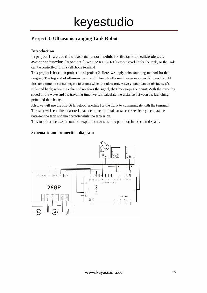
Schematic and connection diagram
keyestudio
www.keyestudio.cc 26
Ultrasonic ranging Tank Robot program
/*
L = Left
R = Right
F = forward
B = backward
*/
#include <Servo.h>
int pinLB = 12; // define pin 12
int pinLF = 3; // define pin 3
int pinRB = 13; // define pin 13
int pinRF = 11; // define pin 11
////////////////////////////////
int inputPin = 4; // define pin for sensor echo
int outputPin =5; // define pin for sensor trig
int Fspeedd = 0; // forward speed
int Rspeedd = 0; // right speed
int Lspeedd = 0; // left speed
int directionn = 0; // forward=8 backward=2 left=4 right=6
Servo myservo; // set myservo
int delay_time = 250; // settling time after steering servo motor moving B
int Fgo = 8; // Move F
int Rgo = 6; // move to the R
int Lgo = 4; // move to the L
int Bgo = 2; // move B
void setup()
{
keyestudio
www.keyestudio.cc 27
Serial.begin(9600); // Define motor output pin
pinMode(pinLB,OUTPUT); // pin 12
pinMode(pinLF,OUTPUT); // pin 3 (PWM)
pinMode(pinRB,OUTPUT); // pin 13
pinMode(pinRF,OUTPUT); // pin 11 (PWM)
pinMode(inputPin, INPUT); // define input pin for sensor
pinMode(outputPin, OUTPUT); // define output pin for sensor
myservo.attach(9); // Define servo motor output pin to D9 (PWM)
}
void advance() // move forward
{
digitalWrite(pinLB,LOW); // right wheel moves forward
digitalWrite(pinRB, LOW); // left wheel moves forward
analogWrite(pinLF,255);
analogWrite(pinRF,255);
}
void stopp() // stop
{
digitalWrite(pinLB,HIGH);
digitalWrite(pinRB,HIGH);
analogWrite(pinLF,0);
analogWrite(pinRF,0);
}
void right() // turn right (single wheel)
{
digitalWrite(pinLB,HIGH); // wheel on the left moves forward
digitalWrite(pinRB,LOW); // wheel on the right moves backward
analogWrite(pinLF, 255);
analogWrite(pinRF,255);
}
void left() // turn left (single wheel)
{
digitalWrite(pinLB,LOW); // wheel on the left moves backward
digitalWrite(pinRB,HIGH); // wheel on the right moves forward
analogWrite(pinLF, 255);
analogWrite(pinRF,255);
}
void back() // move backward
{
digitalWrite(pinLB,HIGH); // motor moves to left rear
digitalWrite(pinRB,HIGH); // motor moves to right rear
keyestudio
www.keyestudio.cc 28
analogWrite(pinLF,255);
analogWrite(pinRF,255);
}
void detection() // measure 3 angles (0.90.179)
{
int delay_time = 250; // stabilizing time for servo motor after moving backward
ask_pin_F(); // read the distance ahead
if(Fspeedd < 10) // if distance ahead is <10cm
{
stopp(); // clear data
delay(100);
back(); // move backward for 0.2S
delay(200);
}
if(Fspeedd < 25) // if distance ahead is <25cm
{
stopp();
delay(100); // clear data
ask_pin_L(); // read distance on the left
delay(delay_time); // stabilizing time for servo motor
ask_pin_R(); // read distance on the right
delay(delay_time); // stabilizing time for servo motor
if(Lspeedd > Rspeedd) // if distance on the left is >distance on the right
{
directionn = Lgo; // move to the L
}
if(Lspeedd <= Rspeedd) // if distance on the left is <= distance on the right
{
directionn = Rgo; // move to the right
}
if (Lspeedd < 10 && Rspeedd < 10) // if distance on left and right are both <10cm
{
directionn = Bgo; // move backward
}
}
else // if distance ahead is >25cm
{
directionn = Fgo; // move forward
}
keyestudio
www.keyestudio.cc 29
}
void ask_pin_F() // measure the distance ahead
{
myservo.write(90);
digitalWrite(outputPin, LOW); // ultrasonic sensor transmit low level signal 2μs
delayMicroseconds(2);
digitalWrite(outputPin, HIGH); // ultrasonic sensor transmit high level signal10μs, at
least 10μs
delayMicroseconds(10);
digitalWrite(outputPin, LOW); // keep transmitting low level signal
float Fdistance = pulseIn(inputPin, HIGH); // read the time in between
Fdistance= Fdistance/5.8/10; // convert time into distance (unit: cm)
Fspeedd = Fdistance; // read the distance into Fspeedd
Serial.print("Fspeedd = ");
Serial.print(Fspeedd );
Serial.println(" cm");
}
void ask_pin_L() // measure distance on the left
{
myservo.write(5);
delay(delay_time);
digitalWrite(outputPin, LOW); // ultrasonic sensor transmit low level signal 2μs
delayMicroseconds(2);
digitalWrite(outputPin, HIGH); // ultrasonic sensor transmit high level signal10μs, at
least 10μs
delayMicroseconds(10);
digitalWrite(outputPin, LOW); // keep transmitting low level signal
float Ldistance = pulseIn(inputPin, HIGH); // read the time in between
Ldistance= Ldistance/5.8/10; // convert time into distance (unit: cm)
Lspeedd = Ldistance; // read the distance into Lspeedd
Serial.print("Lspeedd = ");
Serial.print(Lspeedd );
Serial.print(" cm ");
}
void ask_pin_R() // measure distance on the right
{
myservo.write(177);
delay(delay_time);
digitalWrite(outputPin, LOW); // ultrasonic sensor transmit low level signal 2μs
delayMicroseconds(2);
digitalWrite(outputPin, HIGH); // ultrasonic sensor transmit high level signal10μs, at
keyestudio
www.keyestudio.cc 30
least 10μs
delayMicroseconds(10);
digitalWrite(outputPin, LOW); // keep transmitting low level signal
float Rdistance = pulseIn(inputPin, HIGH); // read the time in between
Rdistance= Rdistance/5.8/10; // convert time into distance (unit: cm)
Rspeedd = Rdistance; // read the distance into Rspeedd
Serial.print(" Rspeedd = ");
Serial.print(Rspeedd );
Serial.println(" cm");
}
void loop()
{
myservo.write(90); // home set the servo motor, ready for next measurement
detection(); // measure the angle and determine which direction to move
if(directionn == 2) // if directionn= 2
{
back();
delay(800); // go backward
left() ;
delay(200); // Move slightly to the left (to prevent stuck in dead end)
}
if(directionn == 6) // if directionn = 6
{
back();
delay(100);
right();
delay(600); // turn right
}
if(directionn == 4) // if directionn = 4
{
back();
delay(600);
left();
delay(600); // turn left
}
if(directionn == 8) // if directionn = 8
{
advance(); // move forward
delay(100);
}
}


![[XLS]dep.ky.govdep.ky.gov/formslibrary/Documents/TankSpreadsheetv6a.xls · Web viewHints Glossary Tank#10 Tank#9 Tank#8 Tank#7 Tank#6 Tank#5 Tank#4 Tank#3 Tank#2 Tank#1 Summary Instructions](https://static.fdocuments.in/doc/165x107/5ab43ede7f8b9a1a048ba1de/xlsdepky-viewhints-glossary-tank10-tank9-tank8-tank7-tank6-tank5-tank4.jpg)