Keyboard300 Quick Start Guide - IC Realtime · 5 Keyboard Control NVS ... ID ID shortcut Shortcut...
31
Keyboard300 Quick Start Guide Version 1.0.0
Transcript of Keyboard300 Quick Start Guide - IC Realtime · 5 Keyboard Control NVS ... ID ID shortcut Shortcut...
Keyboard300 Quick Start Guide
Version 1.0.0
i
Table of Contents
1 Features and Specifications ....................................................................................... 1
1.1 Features ............................................................................................................. 1
1.2 Front Panel ......................................................................................................... 1
1.3 Rear Panel ......................................................................................................... 2
1.4 Port Features ..................................................................................................... 3
1.5 Power .................................................................................................................. 3
2 Menu Operation ........................................................................................................... 4
2.1 Boot up and Shut down ..................................................................................... 4
2.1.1 Boot up ..................................................................................................... 4
2.1.2 Shut Down ................................................................................................ 4
2.2 Main Menu List................................................................................................... 4
2.3 Menu Operation ................................................................................................. 5
2.3.1 System ...................................................................................................... 5
2.3.2 Control point ............................................................................................. 7
2.3.3 Account ..................................................................................................... 8
2.3.4 Version ..................................................................................................... 9
2.3.5 Model ........................................................................................................ 9
2.4 Zones ................................................................................................................ 10
3 Keyboard Control DVR .............................................................................................. 11
3.1 Connection ....................................................................................................... 11
3.1.1 RS232 Serial Port Connection ............................................................. 11
3.1.2 Via RS485 Connection .......................................................................... 11
3.1.3 Multi-keyboard link via RS485 .............................................................. 11
3.2 Network Connection (For network keyboard only) ....................................... 12
3.2.1 RJ45 port connection ............................................................................ 12
3.3 DVR and Keyboard Setup .............................................................................. 13
3.3.1 DVR Setup ............................................................................................. 13
3.3.2 Network Connection Setup ................................................................... 13
ii
3.4 Operation .......................................................................................................... 14
3.4.1 Login ....................................................................................................... 14
3.4.2 Logout ..................................................................................................... 14
3.4.3 Playback ................................................................................................. 14
3.4.4 Record .................................................................................................... 14
3.4.5 PTZ Control and Video Color ............................................................... 14
3.4.6 Tour ......................................................................................................... 15
3.4.7 1-Window/Multiple-Window Switch ...................................................... 15
4 Network Keyboard Control Speed Dome ................................................................ 16
4.1 Cable Connection ............................................................................................ 16
4.2 Keyboard Setup ............................................................................................... 16
4.3 Operation .......................................................................................................... 16
4.3.1 Speed Dome Menu ............................................................................... 16
4.3.2 Iris/Zoom/Focus ..................................................................................... 17
4.3.3 Preset ..................................................................................................... 17
4.3.4 Scan ........................................................................................................ 17
4.3.5 Pan .......................................................................................................... 18
4.3.6 Tour ......................................................................................................... 18
4.3.7 Pattern .................................................................................................... 19
5 Keyboard Control NVS .............................................................................................. 20
5.1 Connection ....................................................................................................... 20
5.2 Keyboard Setup ............................................................................................... 20
5.3 Operation .......................................................................................................... 20
5.3.1 Login ....................................................................................................... 20
5.3.2 Exit .......................................................................................................... 20
5.3.3 1-Window/Multiple-Window Switch ...................................................... 20
6 Keyboard Upgrade .................................................................................................... 22
6.1 Control Keyboard Upgrade ............................................................................. 22
6.2 Network Keyboard Upgrade ........................................................................... 22
7 Make COM Cable ...................................................................................................... 23
7.1 Make RS232 COM Cable ............................................................................... 23
iii
7.2 Make RS485 COM Cable ............................................................................... 23
7.3 25-pin Port and Switch Box Connection ........................................................ 23
Appendix Toxic or Hazardous Materials or Elements ................................................... 25

iv
Welcome
Thank you for purchasing our keyboard!
This quick start guide is designed to be a reference tool for the operation of your system.
Before the operation please read the following safeguards and warnings carefully!
Please keep it well for future reference.

v
Important Safeguarding and Warnings
1.Electrical safety
All installation and operation here should conform to your local electrical safety codes.
We assume no liability or responsibility for all the fires or electrical shock caused by improper
handling or installation.
2.Transportation security
Heavy stress, violent vibration or water splash are not allowed during transportation, storage and
installation.
3.Installation
Keep upwards. Handle with care.
Do not place objects on the network keyboard
4.Qualified engineers needed
All the examination and repair work should be done by the qualified service engineers.
We are not liable for any problems caused by unauthorized modifications or attempted repair.
5.Environment
The keyboard should be used in a cool, dry place away from direct sunlight, inflammable,
explosive substances and etc.
6. Accessories
Be sure to use all the accessories recommended by manufacturer.
Before installation, please open the package and check all the components are included.
1
1 Features and Specifications
1.1 Features
This series keyboard has the following features
One keyboard can control multiple DVRs, or you can use multiple keyboards to control one
DVR.
Support dome operation.
Support RS485 port and RS232 port.
Support PTZ operation via joystick
Support all operations you get from DVR front panel function keys
Support keyboard lock function
Support multiple-level operation rights
Support cascade connection
Support single or multiple DVRs’s menu setup
On-screen menu, user-friendly procedure. It is very easy for you to operate
Can control network video server and network video decoder
Support network ports connection
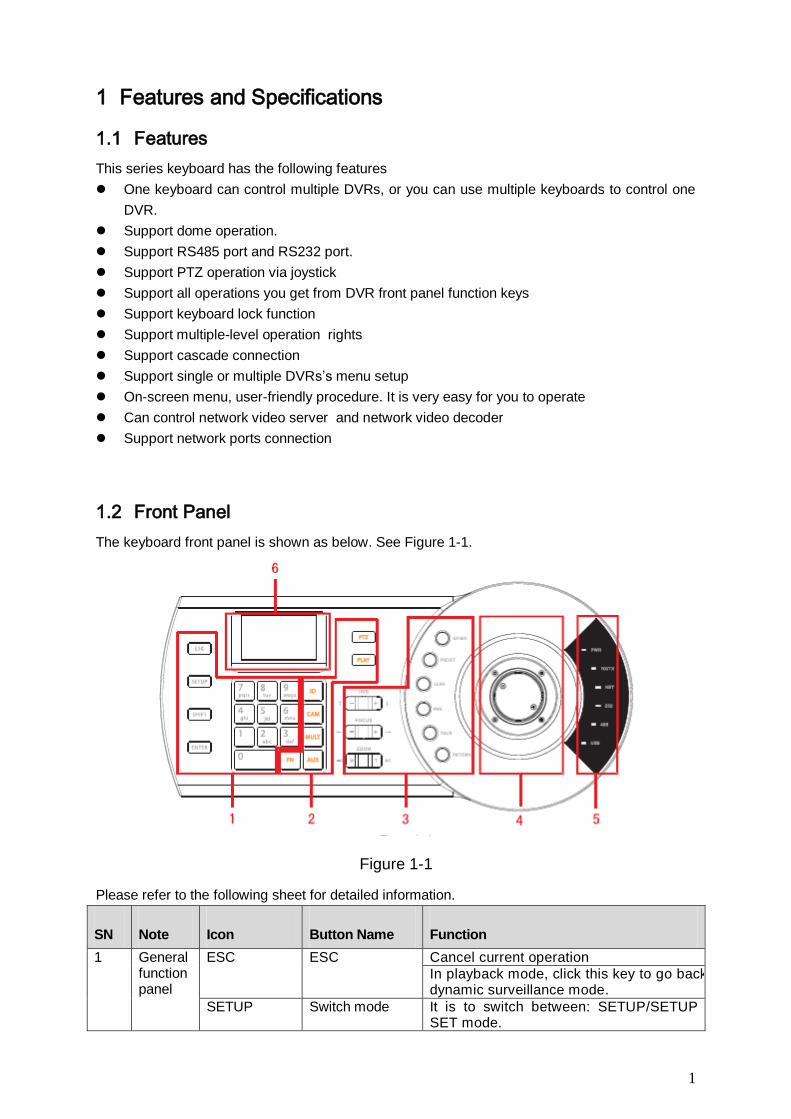
1.2 Front Panel
The keyboard front panel is shown as below. See Figure 1-1.
Figure 1-1
Please refer to the following sheet for detailed information.
SN Note Icon Button Name Function
1 General function panel
ESC ESC Cancel current operation
In playback mode, click this key to go back to dynamic surveillance mode.
SETUP Switch mode It is to switch between: SETUP/SETUP SET mode.
2
SN Note Icon Button Name Function
In SETUP mode, system supports
【 MULT 】 , 【 CAM 】 , 【 PTZ 】
combination operation.
SHIFT Change input method
Switch between input methods
ENTER Confirm button Confirm current operation
0~9 Character and numerals
Switch between numeral/characters, click Shift to switch.
2 DVR control panel
ID ID shortcut Shortcut key to go to ID zone search
CAM Device channel number
Control DVR channel.
MULT Split button Control DVR window split
AUX Auxiliary Go to video color interface and open DVR local PTZ interface.
FN Function key Work with the number buttons.
【FN】+1: Go to DVR assistant interface.
【FN】+2: Tour
PTZ PTZ button Control channel PTZ.
PLAY Playback button Control DVR playback
3 Speed dome control panel
IRIS iris Control iris.
FOCUS focus Control focus
ZOOM zoom Control zoom.
OTHER Speed dome menu
Go to speed dome menu.
PERSET Preset Go to preset setup interface.
SCAN Scan Go to scan setup interface.
PAN Pan Go to pan setup menu.
TOUR Tour Go to tour setup menu.
PATTERN Pattern Go to pattern setup menu.
4 Joystick
- - Aux menu and function operation.
5 Indicator light panel
PWR Power indicator light
The light is on when the keyboard is properly connected to the power supplying.
TR/TX Network data receive and send indicator light
The light is flashing when the keyboard is connected to the network.
NET Network indicator light
The light is on when the device is connected to the network.
232 RS232 indicator light
The light is flashing when there is 232 data transmission.
485 RS485 indicator light
The light is flashing when there is 485 data transmission.
USB USB indicator light
The light is on when the keyboard is connected to the USB device. The light is on when the keyboard is connected to the PC.
6 LCD - - OSD menu
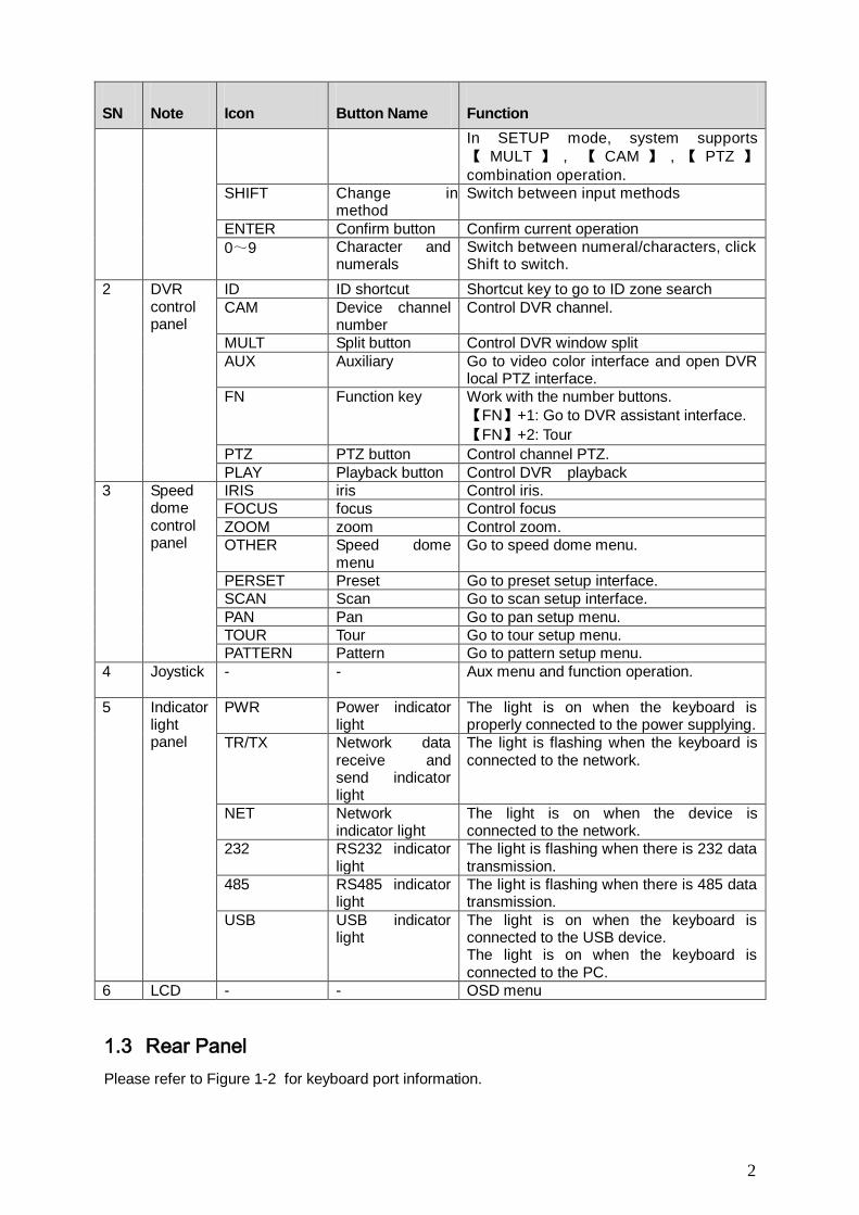
1.3 Rear Panel
Please refer to Figure 1-2 for keyboard port information.
3
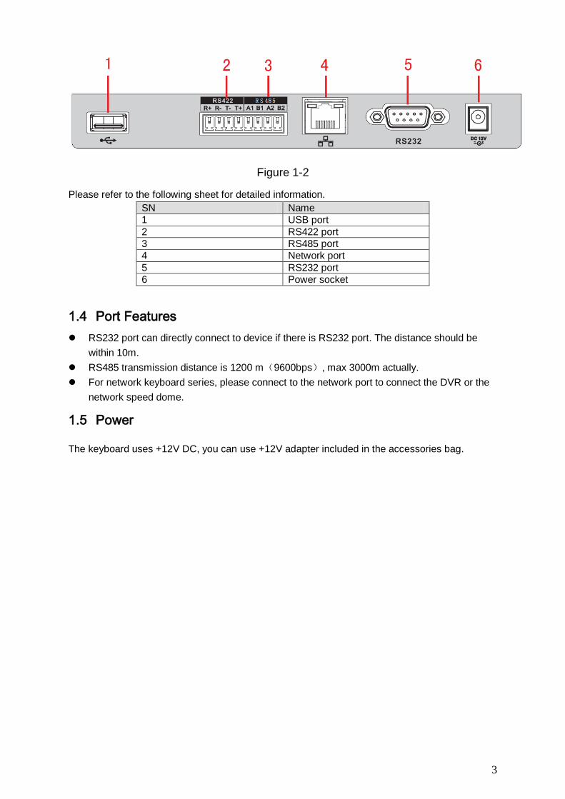
Figure 1-2
Please refer to the following sheet for detailed information.
SN Name
1 USB port
2 RS422 port
3 RS485 port
4 Network port
5 RS232 port
6 Power socket
1.4 Port Features
RS232 port can directly connect to device if there is RS232 port. The distance should be
within 10m.
RS485 transmission distance is 1200 m(9600bps), max 3000m actually.
For network keyboard series, please connect to the network port to connect the DVR or the
network speed dome.
1.5 Power
The keyboard uses +12V DC, you can use +12V adapter included in the accessories bag.
4
2 Menu Operation
2.1 Boot up and Shut down
2.1.1 Boot up
Connect the keyboard to the proper power supplying source. The power indicator light is on. You
can see the welcome interface after the device properly booted up.
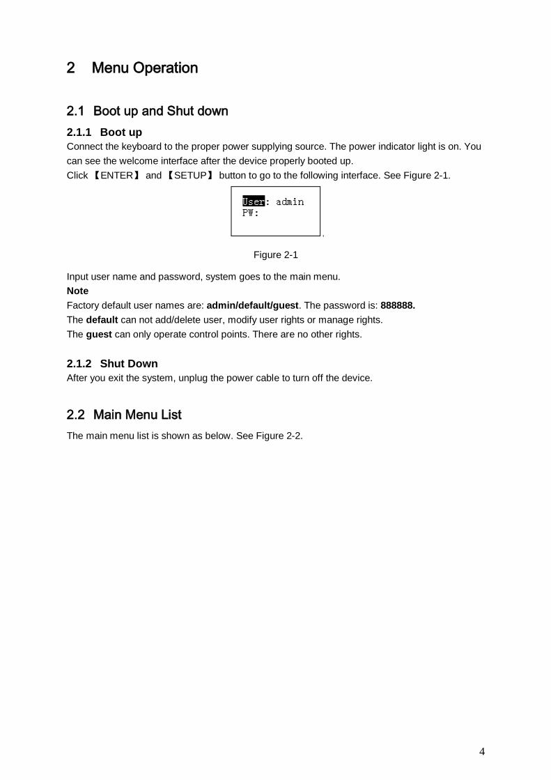
Click 【ENTER】 and 【SETUP】 button to go to the following interface. See Figure 2-1.
Figure 2-1
Input user name and password, system goes to the main menu.
Note
Factory default user names are: admin/default/guest. The password is: 888888.
The default can not add/delete user, modify user rights or manage rights.
The guest can only operate control points. There are no other rights.
2.1.2 Shut Down
After you exit the system, unplug the power cable to turn off the device.
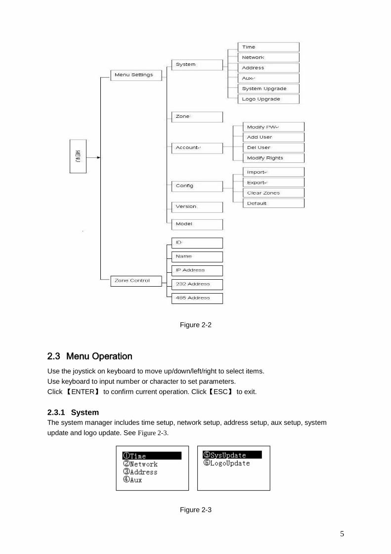
2.2 Main Menu List
The main menu list is shown as below. See Figure 2-2.
5
Figure 2-2
2.3 Menu Operation
Use the joystick on keyboard to move up/down/left/right to select items.
Use keyboard to input number or character to set parameters.
Click 【ENTER】 to confirm current operation. Click【ESC】 to exit.
2.3.1 System
The system manager includes time setup, network setup, address setup, aux setup, system
update and logo update. See Figure 2-3.
Figure 2-3
6
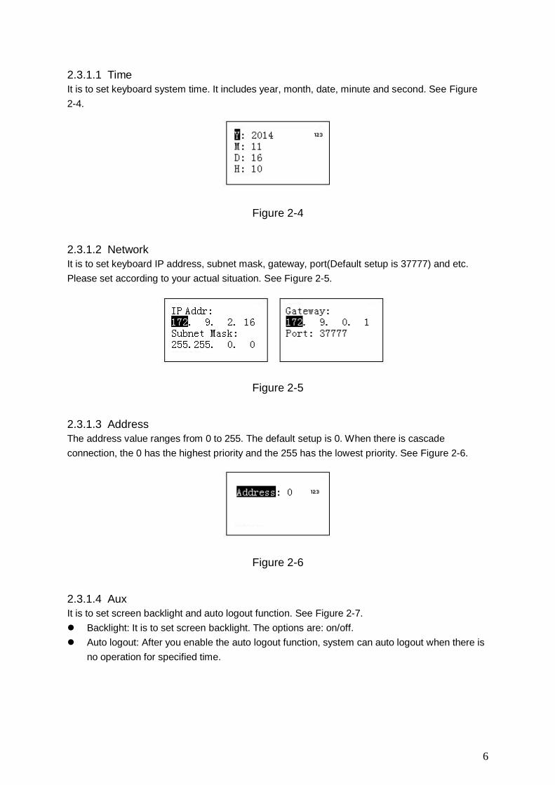
2.3.1.1 Time
It is to set keyboard system time. It includes year, month, date, minute and second. See Figure
2-4.
Figure 2-4
2.3.1.2 Network
It is to set keyboard IP address, subnet mask, gateway, port(Default setup is 37777) and etc.
Please set according to your actual situation. See Figure 2-5.
Figure 2-5
2.3.1.3 Address
The address value ranges from 0 to 255. The default setup is 0. When there is cascade
connection, the 0 has the highest priority and the 255 has the lowest priority. See Figure 2-6.
Figure 2-6
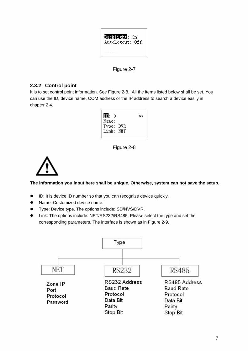
2.3.1.4 Aux
It is to set screen backlight and auto logout function. See Figure 2-7.
Backlight: It is to set screen backlight. The options are: on/off.
Auto logout: After you enable the auto logout function, system can auto logout when there is
no operation for specified time.
7
Figure 2-7
2.3.2 Control point
It is to set control point information. See Figure 2-8. All the items listed below shall be set. You
can use the ID, device name, COM address or the IP address to search a device easily in
chapter 2.4.
Figure 2-8
The information you input here shall be unique. Otherwise, system can not save the setup.
ID: It is device ID number so that you can recognize device quickly.
Name: Customized device name.
Type: Device type. The options include: SD/NVS/DVR.
Link: The options include: NET/RS232/RS485. Please select the type and set the
corresponding parameters. The interface is shown as in Figure 2-9.
8
Figure 2-9
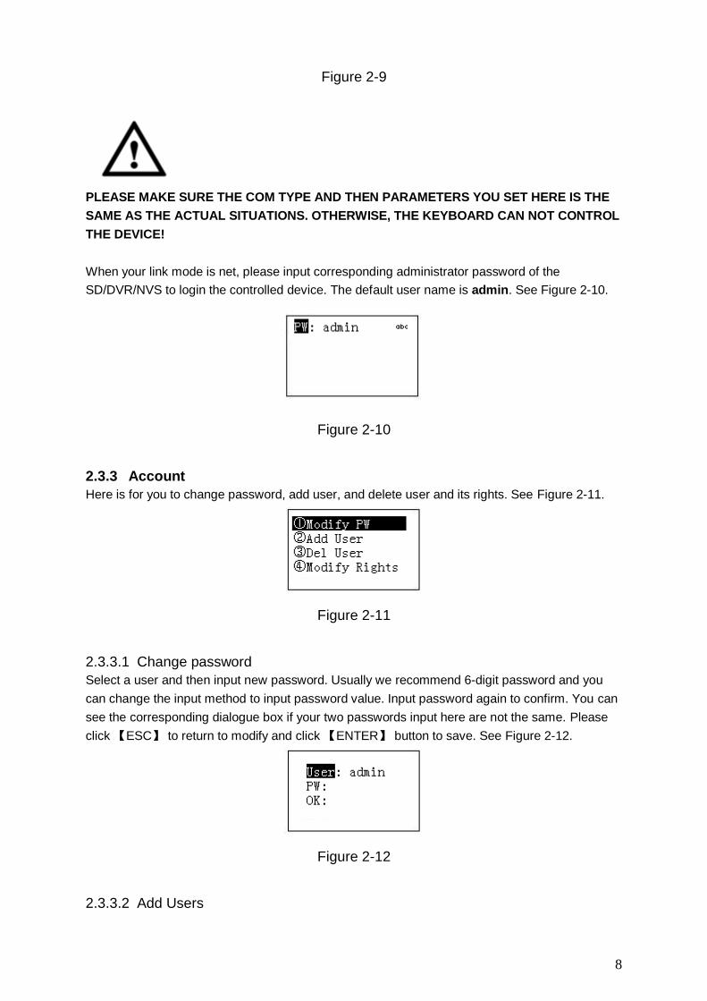
PLEASE MAKE SURE THE COM TYPE AND THEN PARAMETERS YOU SET HERE IS THE
SAME AS THE ACTUAL SITUATIONS. OTHERWISE, THE KEYBOARD CAN NOT CONTROL
THE DEVICE!
When your link mode is net, please input corresponding administrator password of the
SD/DVR/NVS to login the controlled device. The default user name is admin. See Figure 2-10.
Figure 2-10
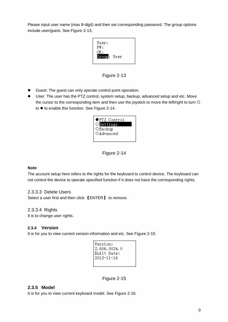
2.3.3 Account
Here is for you to change password, add user, and delete user and its rights. See Figure 2-11.
Figure 2-11
2.3.3.1 Change password
Select a user and then input new password. Usually we recommend 6-digit password and you
can change the input method to input password value. Input password again to confirm. You can
see the corresponding dialogue box if your two passwords input here are not the same. Please
click 【ESC】 to return to modify and click 【ENTER】 button to save. See Figure 2-12.
Figure 2-12
2.3.3.2 Add Users
9
Please input user name (max 8-digit) and then set corresponding password. The group options
include user/guest. See Figure 2-13,
Figure 2-13
Guest: The guest can only operate control point operation.
User: The user has the PTZ control, system setup, backup, advanced setup and etc. Move
the cursor to the corresponding item and then use the joystick to move the left/right to turn
to to enable this function. See Figure 2-14.
Figure 2-14
Note
The account setup here refers to the rights for the keyboard to control device. The keyboard can
not control the device to operate specified function if it does not have the corresponding rights.
2.3.3.3 Delete Users
Select a user first and then click 【ENTER】 to remove.
2.3.3.4 Rights
It is to change user rights.
2.3.4 Version
It is for you to view current version information and etc. See Figure 2-15.
Figure 2-15
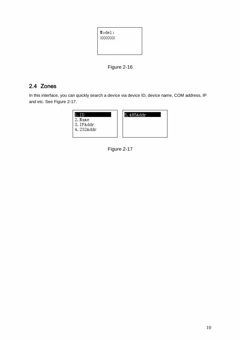
2.3.5 Model
It is for you to view current keyboard model. See Figure 2-16.
10
Figure 2-16
2.4 Zones
In this interface, you can quickly search a device via device ID, device name, COM address, IP
and etc. See Figure 2-17.
Figure 2-17
11
3 Keyboard Control DVR
3.1 Connection
3.1.1 RS232 Serial Port Connection
You can use one RS232 cable to connect DVR serial port and keyboard serial port together.
DVR address number ranges from 1 to 255,please refer to DVR user’s manual for more
information.
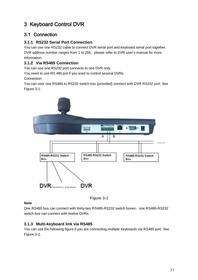
3.1.2 Via RS485 Connection
You can use one RS232 port connects to one DVR only.
You need to use RS 485 pot if you want to control several DVRs.
Connection
You can user one RS485 to RS232 switch box (provided) connect with DVR RS232 port. See
Figure 3-1.
Figure 3-1
Note
One RS485 bus can connect with thirty-two RS485-RS232 switch boxes,one RS485-RS232
switch box can connect with twelve DVRs.
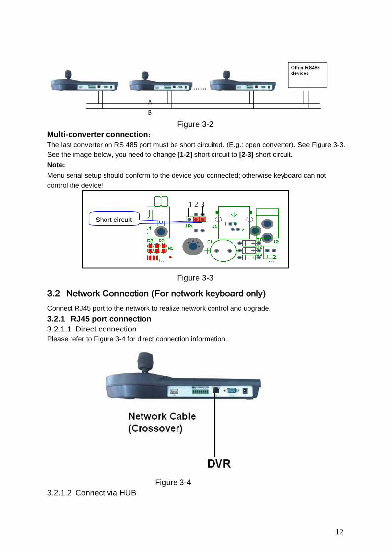
3.1.3 Multi-keyboard link via RS485
You can use the following figure if you are connecting multiple keyboards via RS485 port. See
Figure 3-2.
12
Figure 3-2
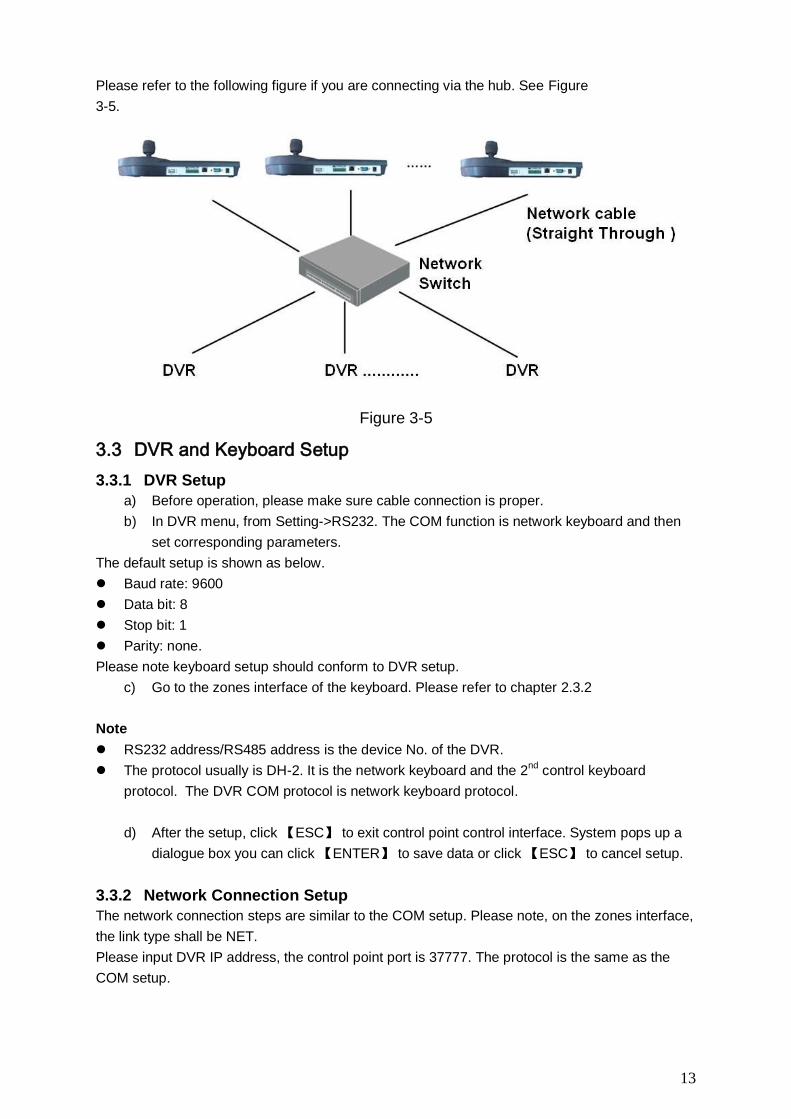
Multi-converter connection:
The last converter on RS 485 port must be short circuited. (E.g.: open converter). See Figure 3-3.
See the image below, you need to change [1-2] short circuit to [2-3] short circuit.
Note:
Menu serial setup should conform to the device you connected; otherwise keyboard can not
control the device!
Figure 3-3
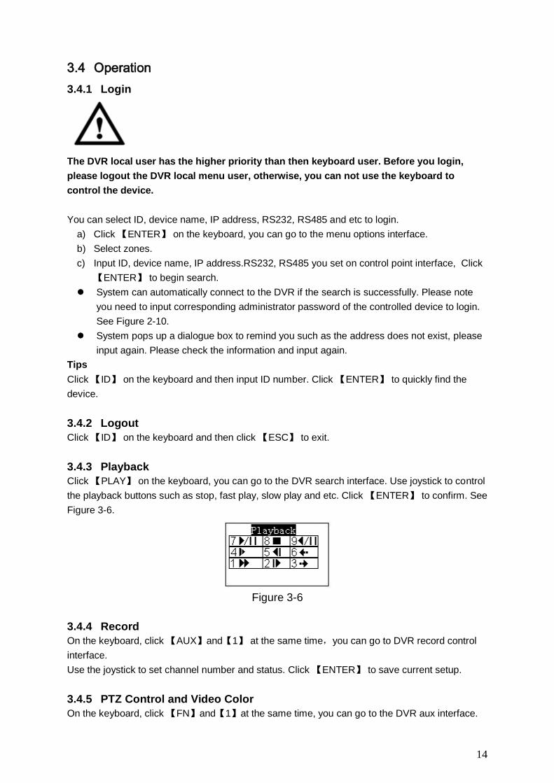
3.2 Network Connection (For network keyboard only)
Connect RJ45 port to the network to realize network control and upgrade.
3.2.1 RJ45 port connection
3.2.1.1 Direct connection
Please refer to Figure 3-4 for direct connection information.
Figure 3-4
3.2.1.2 Connect via HUB
Short circuit
1 2 3
13
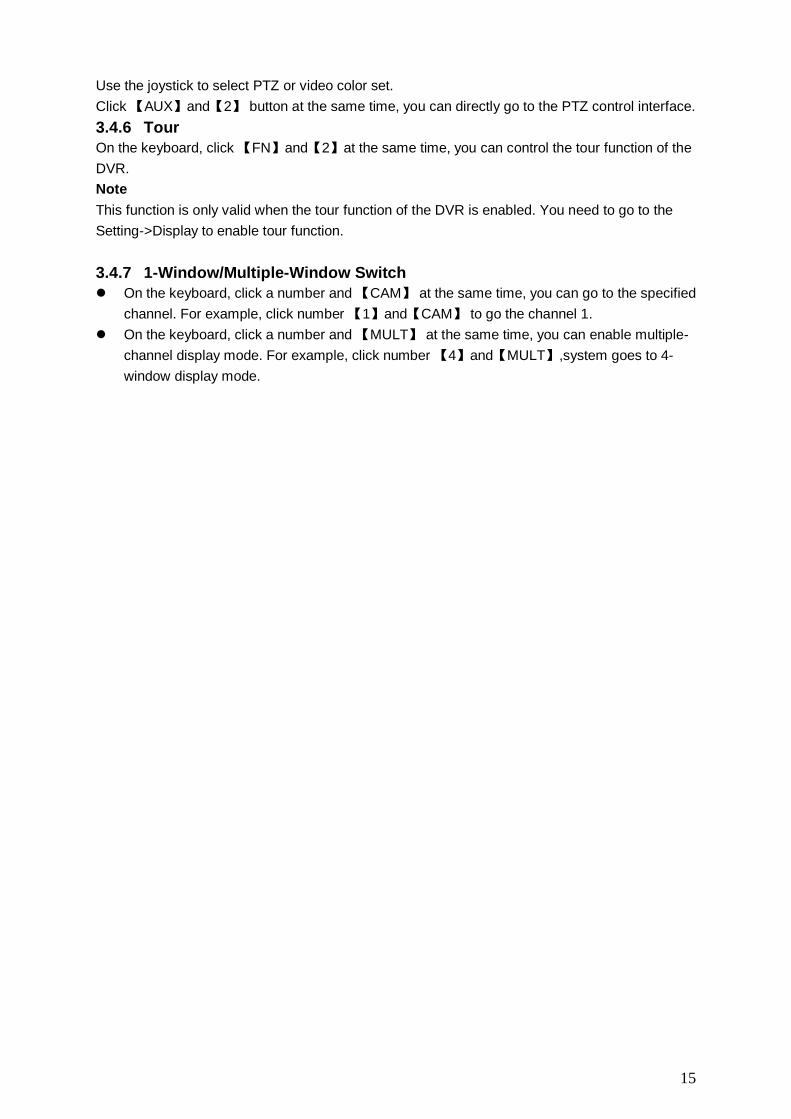
Please refer to the following figure if you are connecting via the hub. See Figure
3-5.
Figure 3-5
3.3 DVR and Keyboard Setup
3.3.1 DVR Setup
a) Before operation, please make sure cable connection is proper.
b) In DVR menu, from Setting->RS232. The COM function is network keyboard and then
set corresponding parameters.
The default setup is shown as below.
Baud rate: 9600
Data bit: 8
Stop bit: 1
Parity: none.
Please note keyboard setup should conform to DVR setup.
c) Go to the zones interface of the keyboard. Please refer to chapter 2.3.2
Note
RS232 address/RS485 address is the device No. of the DVR.
The protocol usually is DH-2. It is the network keyboard and the 2nd
control keyboard
protocol. The DVR COM protocol is network keyboard protocol.
d) After the setup, click 【ESC】 to exit control point control interface. System pops up a
dialogue box you can click 【ENTER】 to save data or click 【ESC】 to cancel setup.
3.3.2 Network Connection Setup
The network connection steps are similar to the COM setup. Please note, on the zones interface,
the link type shall be NET.
Please input DVR IP address, the control point port is 37777. The protocol is the same as the
COM setup.
14
3.4 Operation
3.4.1 Login
The DVR local user has the higher priority than then keyboard user. Before you login,
please logout the DVR local menu user, otherwise, you can not use the keyboard to
control the device.
You can select ID, device name, IP address, RS232, RS485 and etc to login.
a) Click 【ENTER】 on the keyboard, you can go to the menu options interface.
b) Select zones.
c) Input ID, device name, IP address.RS232, RS485 you set on control point interface, Click
【ENTER】 to begin search.
System can automatically connect to the DVR if the search is successfully. Please note
you need to input corresponding administrator password of the controlled device to login.
See Figure 2-10.
System pops up a dialogue box to remind you such as the address does not exist, please
input again. Please check the information and input again.
Tips
Click 【ID】 on the keyboard and then input ID number. Click 【ENTER】 to quickly find the
device.
3.4.2 Logout
Click 【ID】 on the keyboard and then click 【ESC】 to exit.
3.4.3 Playback
Click 【PLAY】 on the keyboard, you can go to the DVR search interface. Use joystick to control
the playback buttons such as stop, fast play, slow play and etc. Click 【ENTER】 to confirm. See
Figure 3-6.
Figure 3-6
3.4.4 Record
On the keyboard, click 【AUX】and【1】 at the same time,you can go to DVR record control
interface.
Use the joystick to set channel number and status. Click 【ENTER】 to save current setup.
3.4.5 PTZ Control and Video Color
On the keyboard, click 【FN】and【1】at the same time, you can go to the DVR aux interface.
15
Use the joystick to select PTZ or video color set.
Click 【AUX】and【2】 button at the same time, you can directly go to the PTZ control interface.
3.4.6 Tour
On the keyboard, click 【FN】and【2】at the same time, you can control the tour function of the
DVR.
Note
This function is only valid when the tour function of the DVR is enabled. You need to go to the
Setting->Display to enable tour function.
3.4.7 1-Window/Multiple-Window Switch
On the keyboard, click a number and 【CAM】 at the same time, you can go to the specified
channel. For example, click number 【1】and【CAM】 to go the channel 1.
On the keyboard, click a number and 【MULT】 at the same time, you can enable multiple-
channel display mode. For example, click number 【4】and【MULT】,system goes to 4-
window display mode.
16
4 Network Keyboard Control Speed Dome
4.1 Cable Connection
Please connect keyboard A/B line to speed dome A/B line connection is right.
4.2 Keyboard Setup
a) Please make sure keyboard A/B line and speed dome A/B line connection is right.
b) Set speed dome address so that the speed dome address and the keyboard RS485
address are the same.
c) Go to the zones interface of the keyboard. Please refer to chapter 2.3.2
Note
Please select protocol according to the speed dome type. The default setup is DH-SD.
Please login WEB of the speed dome, from main interface->Setup->System->PTZ to
view speed dome address, protocol, COM setup and etc.
d) After the setup, click 【ESC】 to exit control point control interface. System pops up a
dialogue box you can click 【ENTER】 to save data or click 【ESC】 to cancel setup.
4.3 Operation
On the keyboard, click 【ID】 to go to the control point interface to set speed dome ID to connect to
the speed dome.
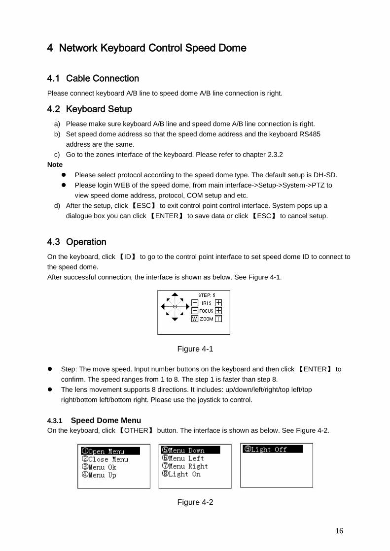
After successful connection, the interface is shown as below. See Figure 4-1.
Figure 4-1
Step: The move speed. Input number buttons on the keyboard and then click 【ENTER】 to
confirm. The speed ranges from 1 to 8. The step 1 is faster than step 8.
The lens movement supports 8 directions. It includes: up/down/left/right/top left/top
right/bottom left/bottom right. Please use the joystick to control.
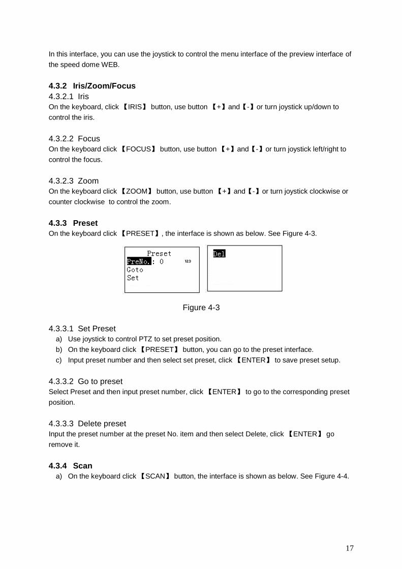
4.3.1 Speed Dome Menu
On the keyboard, click 【OTHER】 button. The interface is shown as below. See Figure 4-2.
Figure 4-2
17
In this interface, you can use the joystick to control the menu interface of the preview interface of
the speed dome WEB.
4.3.2 Iris/Zoom/Focus
4.3.2.1 Iris
On the keyboard, click 【IRIS】 button, use button 【+】and【-】or turn joystick up/down to
control the iris.
4.3.2.2 Focus
On the keyboard click 【FOCUS】 button, use button 【+】and【-】or turn joystick left/right to
control the focus.
4.3.2.3 Zoom
On the keyboard click 【ZOOM】 button, use button 【+】and【-】or turn joystick clockwise or
counter clockwise to control the zoom.
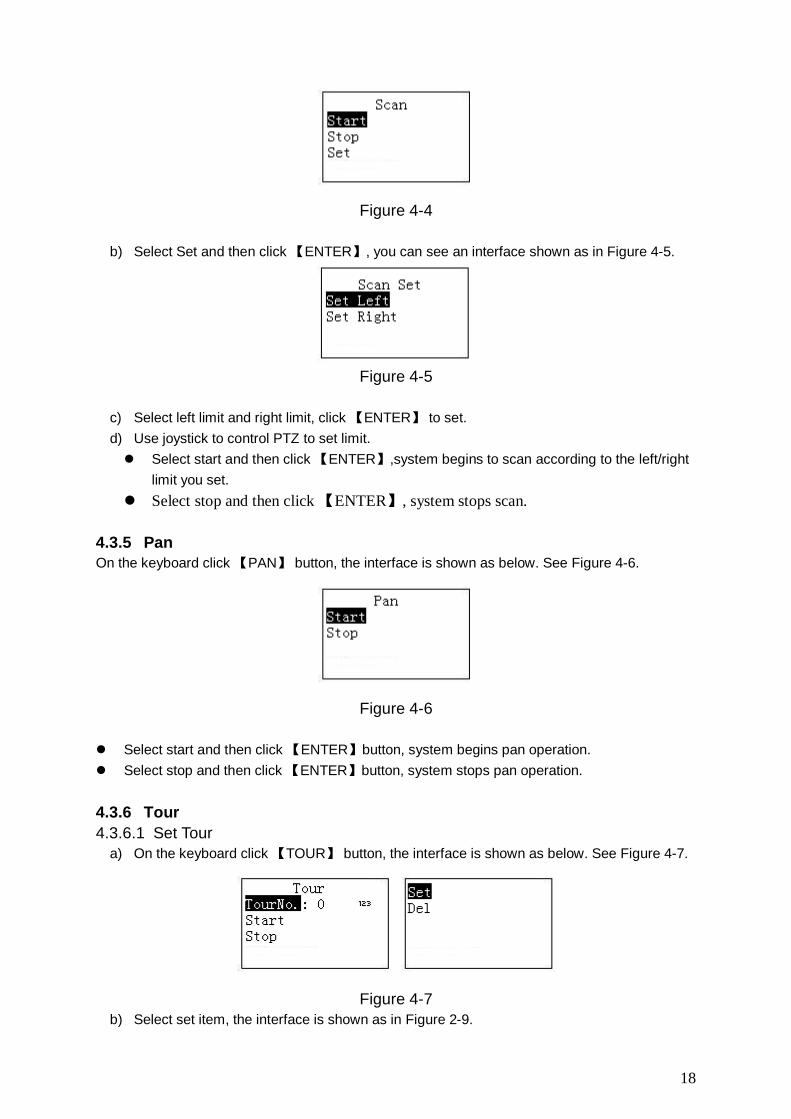
4.3.3 Preset
On the keyboard click 【PRESET】, the interface is shown as below. See Figure 4-3.
Figure 4-3
4.3.3.1 Set Preset
a) Use joystick to control PTZ to set preset position.
b) On the keyboard click 【PRESET】 button, you can go to the preset interface.
c) Input preset number and then select set preset, click 【ENTER】 to save preset setup.
4.3.3.2 Go to preset
Select Preset and then input preset number, click 【ENTER】 to go to the corresponding preset
position.
4.3.3.3 Delete preset
Input the preset number at the preset No. item and then select Delete, click 【ENTER】 go
remove it.
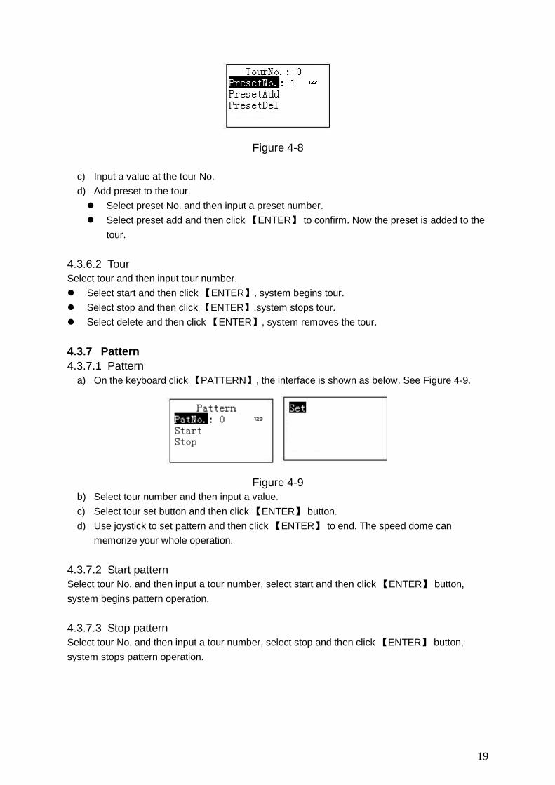
4.3.4 Scan
a) On the keyboard click 【SCAN】 button, the interface is shown as below. See Figure 4-4.
18
Figure 4-4
b) Select Set and then click 【ENTER】, you can see an interface shown as in Figure 4-5.
Figure 4-5
c) Select left limit and right limit, click 【ENTER】 to set.
d) Use joystick to control PTZ to set limit.
Select start and then click 【ENTER】,system begins to scan according to the left/right
limit you set.
Select stop and then click 【ENTER】, system stops scan.
4.3.5 Pan
On the keyboard click 【PAN】 button, the interface is shown as below. See Figure 4-6.
Figure 4-6
Select start and then click 【ENTER】button, system begins pan operation.
Select stop and then click 【ENTER】button, system stops pan operation.
4.3.6 Tour
4.3.6.1 Set Tour
a) On the keyboard click 【TOUR】 button, the interface is shown as below. See Figure 4-7.
Figure 4-7
b) Select set item, the interface is shown as in Figure 2-9.
19
Figure 4-8
c) Input a value at the tour No.
d) Add preset to the tour.
Select preset No. and then input a preset number.
Select preset add and then click 【ENTER】 to confirm. Now the preset is added to the
tour.
4.3.6.2 Tour
Select tour and then input tour number.
Select start and then click 【ENTER】, system begins tour.
Select stop and then click 【ENTER】,system stops tour.
Select delete and then click 【ENTER】, system removes the tour.
4.3.7 Pattern
4.3.7.1 Pattern
a) On the keyboard click 【PATTERN】, the interface is shown as below. See Figure 4-9.
Figure 4-9
b) Select tour number and then input a value.
c) Select tour set button and then click 【ENTER】 button.
d) Use joystick to set pattern and then click 【ENTER】 to end. The speed dome can
memorize your whole operation.
4.3.7.2 Start pattern
Select tour No. and then input a tour number, select start and then click 【ENTER】 button,
system begins pattern operation.
4.3.7.3 Stop pattern
Select tour No. and then input a tour number, select stop and then click 【ENTER】 button,
system stops pattern operation.
20
5 Keyboard Control NVS
5.1 Connection
Connect the network cable to the RJ45 network port of the keyboard, now you can implement
network control and upgrade.
5.2 Keyboard Setup
a) On the keyboard to set control point setup, Please refer to chapter 2.3.2. The link type
shall be NET.
Note
Please input NVS IP address and the default port value is 37777.
The protocol usually is DH-2. It is the network keyboard and the 2nd
control keyboard
protocol. The DVR COM protocol is network keyboard protocol.
b) After the setup, click 【ESC】 to exit.
5.3 Operation
5.3.1 Login
a) You can use ID, device name, or IP address to login the device.
b) On the keyboard click 【ENTER】, you can go to the menu option interface.
c) Select control point.
d) Input ID, device name, or IP address and then click 【ENTER】 to search.
System automatically connects to the NVS if the search is successful. Please note you
need to input corresponding administrator password of the NVS to login. See Figure 2-10.
You can see the corresponding dialogue box such as the “IP address does not exist.
Please input again!” Please check the information and input again.
Tips
On the keyboard click 【ID】and then input ID, click 【ENTER】 button to quickly find ID and
connect to the device you want to control.
5.3.2 Exit
On the keyboard click 【ID】 and then click 【ESC】, you can exit menu.
5.3.3 1-Window/Multiple-Window Switch
On the keyboard, click a number and 【AUX】 at the same time to select corresponding
VGA port number. For example, click number 【1】and【AUX】 to go to video from the
VGA 1.
On the keyboard, click a number and 【CAM】 at the same time, you can go to the specified
channel. For example, click number 【1】and【CAM】 to go the channel 1.Or you can click
a number and 【SETUP】 to go to a channel. But the value here ranges from 1 to 9. That is
to say, you can go to channel 1-channel 9 only.
21
On the keyboard, click a number and 【MULT】 at the same time, you can enable multiple-
channel display mode. For example, click number 【4】and【MULT】,system goes to 4-
window display mode.
22
6 Keyboard Upgrade
6.1 Control Keyboard Upgrade
Control keyboard does not support remote upgrade. Please ship your control keyboard back to
our factory to upgrade.
6.2 Network Keyboard Upgrade
Before upgrade, please make sure your network keyboard is well connected. You can use
command “PING” to test network connection, the return value TTL should be less than 255.
Please download upgrade file to your local PC. You can download upgrade file from our website
or from our local service engineer.
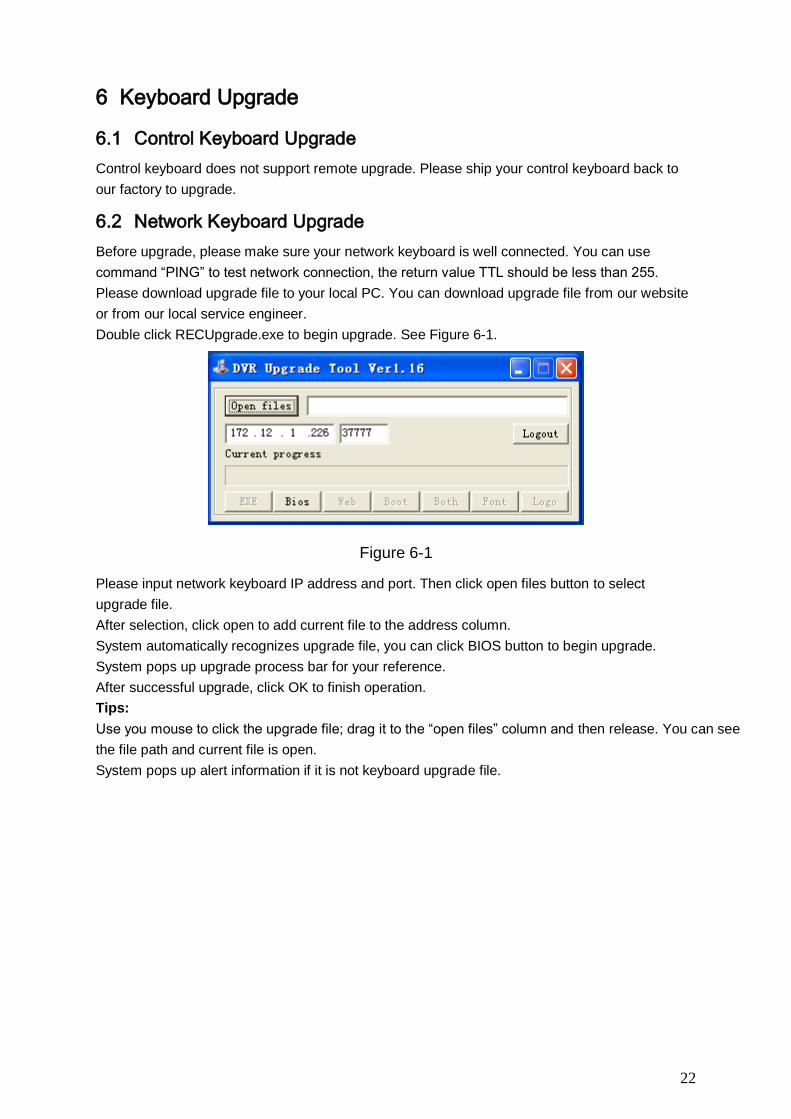
Double click RECUpgrade.exe to begin upgrade. See Figure 6-1.
Figure 6-1
Please input network keyboard IP address and port. Then click open files button to select
upgrade file.
After selection, click open to add current file to the address column.
System automatically recognizes upgrade file, you can click BIOS button to begin upgrade.
System pops up upgrade process bar for your reference.
After successful upgrade, click OK to finish operation.
Tips:
Use you mouse to click the upgrade file; drag it to the “open files” column and then release. You can see
the file path and current file is open.
System pops up alert information if it is not keyboard upgrade file.
23
7 Make COM Cable
The keyboard standard accessories bag includes the following items:
One DB9
Seven DB9
One six-pin crystal port
One 25-pin (DB25)
One 485 switch box. (Including one power sourcing.)
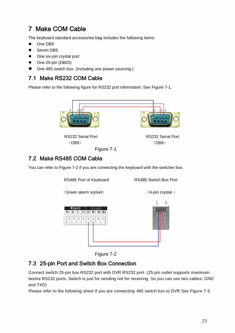
7.1 Make RS232 COM Cable
Please refer to the following figure for RS232 port information. See Figure 7-1.
RS232 Serial Port RS232 Serial Port
(DB9) (DB9)
Figure 7-1
7.2 Make RS485 COM Cable
You can refer to Figure 7-2 if you are connecting the keyboard with the switcher box.
RS485 Port of Keyboard RS485 Switch Box Port
(Green alarm socket) (6-pin crystal )
Figure 7-2
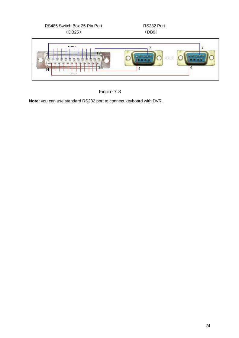
7.3 25-pin Port and Switch Box Connection
Connect switch 25-pin box RS232 port with DVR RS232 port. (25-pin outlet supports maximum
twelve RS232 ports. Switch is just for sending not for receiving. So you can use two cables: GND
and TXD)
Please refer to the following sheet if you are connecting 485 switch box to DVR See Figure 7-3.
24
RS485 Switch Box 25-Pin Port RS232 Port
(DB25) (DB9)
Figure 7-3
Note: you can use standard RS232 port to connect keyboard with DVR.
25
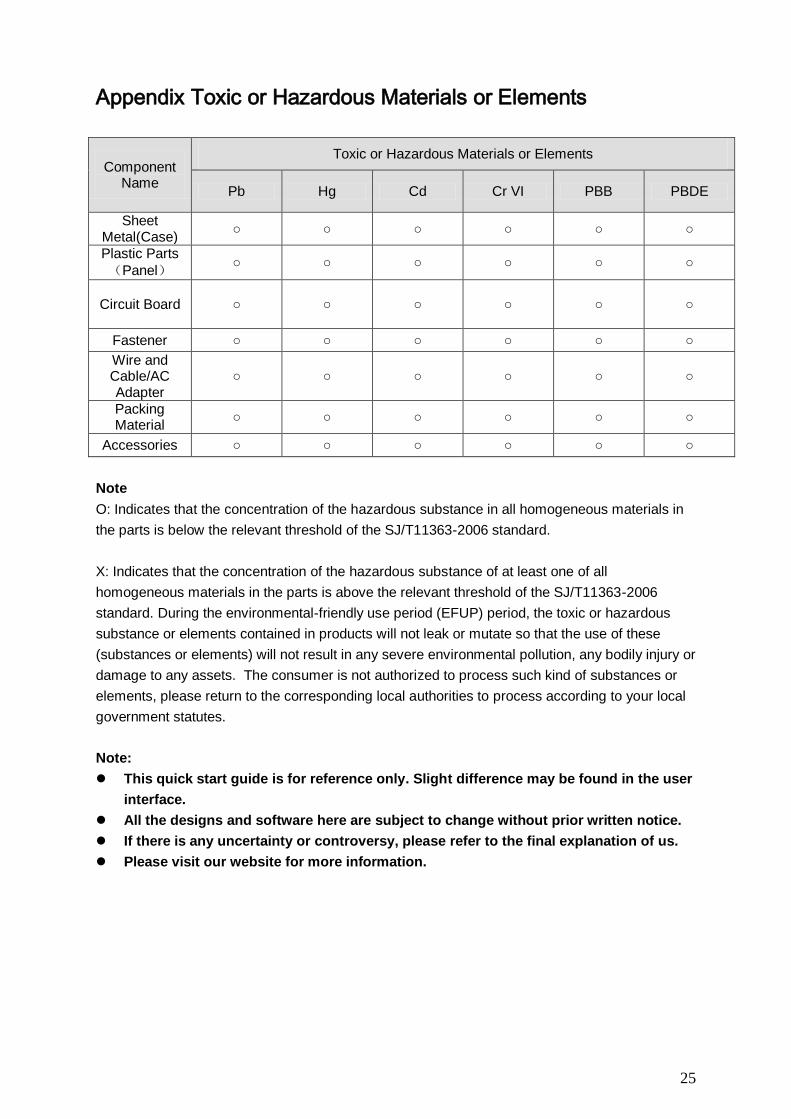
Appendix Toxic or Hazardous Materials or Elements
Component Name
Toxic or Hazardous Materials or Elements
Pb Hg Cd Cr VI PBB PBDE
Sheet Metal(Case)
○ ○ ○ ○ ○ ○
Plastic Parts
(Panel) ○ ○ ○ ○ ○ ○
Circuit Board ○ ○ ○ ○ ○ ○
Fastener ○ ○ ○ ○ ○ ○
Wire and Cable/AC Adapter
○ ○ ○ ○ ○ ○
Packing Material
○ ○ ○ ○ ○ ○
Accessories ○ ○ ○ ○ ○ ○
Note
O: Indicates that the concentration of the hazardous substance in all homogeneous materials in
the parts is below the relevant threshold of the SJ/T11363-2006 standard.
X: Indicates that the concentration of the hazardous substance of at least one of all
homogeneous materials in the parts is above the relevant threshold of the SJ/T11363-2006
standard. During the environmental-friendly use period (EFUP) period, the toxic or hazardous
substance or elements contained in products will not leak or mutate so that the use of these
(substances or elements) will not result in any severe environmental pollution, any bodily injury or
damage to any assets. The consumer is not authorized to process such kind of substances or
elements, please return to the corresponding local authorities to process according to your local
government statutes.
Note:
This quick start guide is for reference only. Slight difference may be found in the user
interface.
All the designs and software here are subject to change without prior written notice.
If there is any uncertainty or controversy, please refer to the final explanation of us.
Please visit our website for more information.