Kee Anchor Operation & Maintenance Manual · Kee Anchor Operation & Maintenance Manual ... point...
23
Kee Anchor Operation & Maintenance Manual SAFETY AT THE HIGHEST LEVEL SAFESITE LIMITED A KEE SAFETY COMPANY
Transcript of Kee Anchor Operation & Maintenance Manual · Kee Anchor Operation & Maintenance Manual ... point...
Kee Anchor Operation & Maintenance Manual
S A F E T Y A T T H E H I G H E S T L E V E L
SAFESITELIM
ITE
D
A K E E S A F E T Y C O M PA N Y

2

3
INTRODUCTIONThe CE Approved Weightanka® is a Portable Deadweight Anchor device which is an item of Personal Protective Equipment (PPE). Weightanka® has been specifically designed to provide short term safety for low frequency operations where collective protection is not provided. The unit is ideal for short termmaintenance operations to flat roofs or to the plant and equipment installed at roof level such as AC units, telecommunications equipment etc. Weightanka® is extremely compact, portable, and easily assembled.
The Weightanka® has been designed to be used with an approved shock absorbing rope grab and rope and full body harness to provide safe access at all times.
The unit is fully galvanised to BS EN ISO 1461: Hot DipGalvanised Coatings Specification and test methods. The Rubber Coated Base Weights are supplied with suction cups. These protect the roof membrane, increase friction resistance and enable the anchor to be used on all roof membranes, even in wet weather.
Weightanka® fully complies with Class E of BS EN 795:Protection against falls from height - Anchor devices -Requirements and testing.
The system also conforms to BS7883 - Code of practice for the design, selection, installation, use and maintenance of anchor devices conforming to BS EN 795 & ISO 14567 - Personal protective equipment for protection against falls from aheight - Single - point anchor devices, and is approved to meet the PPE Directive.
The unit has also been designed to ensure compliance with thefollowing Regulations:
Construction (Design & Management) RegulationsWork at Height RegulationsConstruction (Health, Safety & Welfare) RegulationsWorkplace (Health, Safety & Welfare) RegulationsManual Handling Operations Regulations
BUILDING HEIGHT & SAFE WORKINGIt is essential that a risk assessment is carried out by a competent person to ensure that the product is used safely. Part of the assessment will consider the building’s height and the combination of PPE to be used in conjunction with the Weightanka®.
Safesite recommends that, as far as reasonably practicable, the Weightanka® should be used as a fall restraint solutionrather than fall arrest. When used for fall restraint, theWeightanka® must be used in conjunction with PPE that prevents the operative from reaching the leading edge. Weighanka®should then be positioned so that the rope remains taughtas the user approaches the edge. If the above is not possible and a fall arrest solution is required then a sufficiently detailed risk assessment, method statement and rescue policy must be produced by a competent person. Care must also be taken to use the correct combination of PPE to minimize the distance & consequence of a potential fall.
Kee Anchor System Overview

4
Generally the length of the shock absorbing rope grab deviceshould not exceed the height of the building in order to avoid the possibility of the pendulum effect. To prevent this, the Weightanka® should be placed perpendicular to the leading edge where the operative is likely to be working. The rope grab line should remain taught at all times when working at the leading edge. No part of the Weightanka® should be placed closer than 2.5m from the nearest roof edge. The unit should not be placed on any surfaces affected by ice, grease or similar slippery conditions which may impair the performance of the unit.
ROOF PITCH & SAFE WORKINGWeightanka® can be used on any flat roof or industrial steel cladded pitched roof up to 15° pitch provided that the unit ispositioned on the opposite pitch to where the operative intends to work. When placed on a roof slope, the Weightanka® mustbe at least 2.5m from the ridge. In all cases, the roof structuremust be capable of taking the load of the Weightanka® combined with the weight of the operative, plus any additional equipment required.
LEGAL REQUIREMENTSThe Work at Height Regulations 2005 require that the employer/ building owner has a rescue plan and policy in place for all fall arrest systems.
TESTING & CE APPROVALWeightanka® has been extensively tested by to BS EN 795: Protection against falls from a height - Anchor devices - Requirements and testing. The unit was tested on the following roof surfaces and has been awarded CE Approval accordingly.Single Ply Membrane Paving Slabs HT Mineral Grade Felt AsphaltSwept Stone Chippings Steel Cladding
EN 795 REVIEWThis standard was reviewed & published in 2012 and was hamonised in December 2015. Test houses are now able to provide CE certificates to this new version of the standard. The new version remains very similar to the original and the 100kg test weight remains unchanged, but the free fall distancehas been changed and test houses have to calculate this togenerate a 9kN force.
Full independent test documentation is available upon request.
Once this dynamic load has been applied an additional 200kg static load is applied, thus representing an extreme rescue situation where a rescuer has no choice but to abseil to the casualty.
(Safesite does not recommend connecting a second person [fall arrest] to the system under any circumstances, including in the event of a rescue)
Kee Anchor System Overview

5
STABILISER ARM – DW1014010The Stabiliser Arm is placed on top of adjacent Rubber Coated Base Weights prior to fitting Top and Bottom Cross Arms.Material : galvanised steel to BS EN ISO 1461. Net weight : 3.5kg.
RUBBER COATED BASE WEIGHTS – DW1013010These base weights provide the maximum friction with the roof membrane. Each Rubber Coated Base Weight has a centrally tapped hole to accept the Weight Locating Pin.Material : galvanised steel to BS EN ISO 1461. Net weight : 16kg.
STANDARD WEIGHT – DW1012010The standard weights are Galvanised. The central hole of the standard weights is un-threaded, and designed to accept the unthreaded portion of the Weight Locating Pin. IT IS ESSENTIAL THE CORRECT NUMBER OF WEIGHTS ARE USED DEPENDENT UPON ROOF MEMBRANE.Material : galvanised steel to BS EN ISO 1461. Net weight : 25kg.
BOTTOM CROSS ARM – DW1015B10The Bottom Cross Arm is used to connect the Base Weights.This cross arm has a threaded spreader plate to accept the pedestal fixing bolt. A second tapped hole and spreader plate is provided for use as a restraint anchor point.Material : galvanised steel to BS EN ISO 1461. Net weight : 16kg.
TOP CROSS ARM – DW1015T10The Top Cross Arm is used to connect the Base Weights.Material : galvanised steel to BS EN ISO 1461. Net weight :15kg.
Kee Anchor Components EN 795
1500mm
1600mm
150mmØ22mm
1600mm
1500mm
150mmØ22mm
120mm
356mm
356mm Ø M16
356mm
356mm 120mm
Ø22mm
1110mm
1060mm
80mm
TOMMY BAR – DWATBAR10For use when tightening the eyebolt into the pedestal. The length and diameter of the tommy bar is specially designed to apply the correct force when tightening the eyebolt. The tommy bar should ONLY be used with the eyebolt centrally positioned and with one hand turning each end. NEVER use the tommy bar with the eyebolt positioned at one end as this would result in too much force being applied which could damage the eyebolt.Material : galvanised steel to BS EN ISO 1461. Net weight : 0.15kg.
400mm
Ø 10mm
6
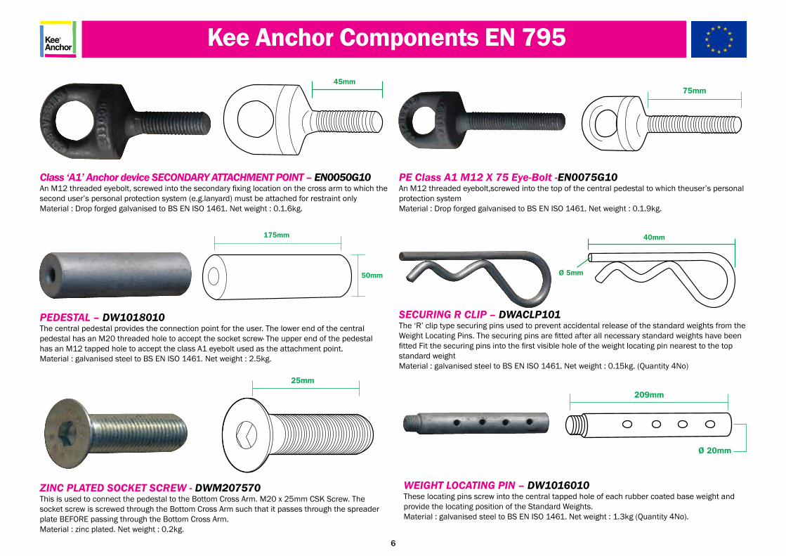
Class ‘A1’ Anchor device SECONDARY ATTACHMENT POINT – EN0050G10An M12 threaded eyebolt, screwed into the secondary fixing location on the cross arm to which the second user’s personal protection system (e.g.lanyard) must be attached for restraint onlyMaterial : Drop forged galvanised to BS EN ISO 1461. Net weight : 0.1.6kg.
ZINC PLATED SOCKET SCREW - DWM207570This is used to connect the pedestal to the Bottom Cross Arm. M20 x 25mm CSK Screw. The socket screw is screwed through the Bottom Cross Arm such that it passes through the spreader plate BEFORE passing through the Bottom Cross Arm.Material : zinc plated. Net weight : 0.2kg.
PE Class A1 M12 X 75 Eye-Bolt -EN0075G10An M12 threaded eyebolt,screwed into the top of the central pedestal to which theuser’s personal protection systemMaterial : Drop forged galvanised to BS EN ISO 1461. Net weight : 0.1.9kg.
PEDESTAL – DW1018010The central pedestal provides the connection point for the user. The lower end of the centralpedestal has an M20 threaded hole to accept the socket screw· The upper end of the pedestalhas an M12 tapped hole to accept the class A1 eyebolt used as the attachment point.Material : galvanised steel to BS EN ISO 1461. Net weight : 2.5kg.
Kee Anchor Components EN 795
75mm45mm
175mm
50mm
25mm
WEIGHT LOCATING PIN – DW1016010These locating pins screw into the central tapped hole of each rubber coated base weight and provide the locating position of the Standard Weights.Material : galvanised steel to BS EN ISO 1461. Net weight : 1.3kg (Quantity 4No).
SECURING R CLIP – DWACLP101The ‘R’ clip type securing pins used to prevent accidental release of the standard weights from the Weight Locating Pins. The securing pins are fitted after all necessary standard weights have been fitted Fit the securing pins into the first visible hole of the weight locating pin nearest to the top standard weightMaterial : galvanised steel to BS EN ISO 1461. Net weight : 0.15kg. (Quantity 4No)
209mm
Ø 20mm
40mm
Ø 5mm

7
Kee Anchor Components EN 795
SYSTEM PLAQUE - SL 111Provides details of the system and approvals. Material : Plastic. Net weight : 1/3 oz.
POLYTHENE WASHER - PWH003840This washer is positioned between the warning disc and the pedestalMaterial : PVC. Net weight : 0.002kg.
PPE WARNING DISC - PP00FA040 or PP00FR040Fall Arrest Warning Disc This disc provides information on use and date of test. Positioned under the eyebolt and above the polythene washer.Material : PVC. Net weight : 0.003kg.
PPE WARNING DISC - PP00FR040Fall Restraint Warning Disc This disc provides information on use and date of test.. Positioned under the eyebolts on central pedestal secondary fixing location on cross arm and above the polythene washer.Material : PVC. Net weight : 0,003kg.
38mm
64mm
64mm

8
Kee Anchor Compliance to EN 795 Class E
MINIMUM EDGE DISTANCE2.5m (8’2”)
WEIGHTANKA
MINIMUM FREE FALL DISTANCE6.75m (22’2”) FALL ARREST
WEIGHTANKA - SEE TABLE FOR TECHNICAL INFORMATION
WEIGHTANKA SYSTEMThe CE Approved Weightanka® is a Portable Deadweight Anchor device which is an item of Personal Protective Equipment (PPE). Weightanka® has been specifically designed to provide short term safety for low frequency operations where collective protection is not provided. The unit is ideal for short term maintenance operations to flat roofs or to the plant and equipment installed at roof level such as AC units, telecommunications equipment etc. Weightanka® is extremely compact, portable, and easily assembled.

9
Kee Anchor Compliance to EN 795 Class E
2.5m (8’2”) Minimum
PITCHED ROOFSAFE WORKING PRACTICE15º Maximum
Type of Roof Surface Quantity of Rubber Weights
Quantity of Galvanised Weights
Bituminous Asphalt
Total Mass - 250kg (551lb 3oz) 4 6
Mineral FeltTotal Mass - 250kg (551lb 3oz) 4 6
Single Ply Membrane (Flat, Smooth)
Total Mass - 300kg (661lb 6oz) 4 8
(Embossed)Total Mass - 400kg (881lb 13oz) 4 12
Loose Stones (All loose stones to be brushed) On Asphalt Base
Total Mass - 250kgs 4 6
On Mastic BaseTotal Mass - 250kg (551lb 3oz) 4 6
Concrete
Total Mass - 250kg (551lb 3oz) 4 6
Steel Cladding Total Mass - 300kg (661lb 6oz) 4 8
WEIGHTANKA PRODUCT

10
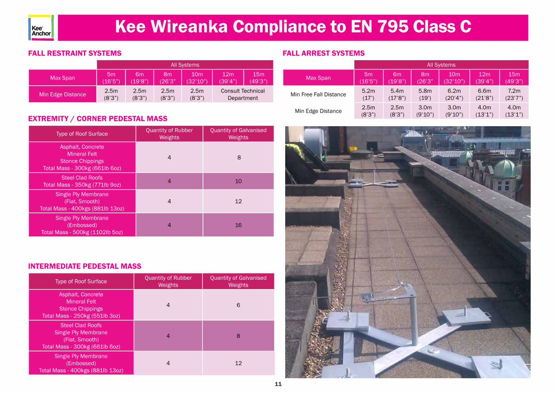
Kee Wireanka Compliance to EN 795 Class CWIREANKA SYSTEMThe Wireanka® System consists of a series of Weightanka’s® linked via the KeeLine® horizontal lifeline system.
Wireanka can be designed as a complete restraint or fall arrest system for up to two users and complies with EN 795 Class C & E and ISO 14567.A series of Weightanka’s® can be linked at approximate 15m centres via the KeeLine® horizontal life line. The KeeLine® horizontal life line provides the operative with hands-free operation so that whena bracket is encountered, the shuttle attaching the operative to the systemglides over the bracket without the need to detach. This type of installation is ideal if a free standing solution is required in order to avoid roof membrane penetration, or the roof design is not suitable for structural fixings associated with horizontal lifeline installations. This configuration of equipment ensures compliance with HSG 33 requiring “demarcated” safe areas/routes to ensure operatives remain within a specific area.
Consideration must be given to ensure that when designed as a “fall restraint” system the operatives remain unable to reach any roof edge/void. It is essential the combination of PPE is appropriate for the particular designed system.
EXTREMITY
INTERMEDIATEMINIMUM EDGEDISTANCE
EXTREMITY
MAXIMUM SPAN
MINIMUM FREE FALLDISTANCE SEE TABLES
TYPICAL WIREANKA LAYOUT - SEE TABLE FOR TECHNICAL INFORMATION
11
Kee Wireanka Compliance to EN 795 Class C
Type of Roof Surface Quantity of Rubber Weights
Quantity of Galvanised Weights
Asphalt, ConcreteMineral Felt
Stonce ChippingsTotal Mass - 250kg (551lb 3oz)
4 6
Steel Clad RoofsSingle Ply Membrane
(Flat, Smooth)Total Mass - 300kg (661lb 6oz)
4 8
Single Ply Membrane(Embossed)
Total Mass - 400kgs (881lb 13oz)4 12
INTERMEDIATE PEDESTAL MASS
Type of Roof Surface Quantity of Rubber Weights
Quantity of Galvanised Weights
Asphalt, ConcreteMineral Felt
Stonce ChippingsTotal Mass - 300kg (661lb 6oz)
4 8
Steel Clad RoofsTotal Mass - 350kg (771lb 9oz) 4 10
Single Ply Membrane(Flat, Smooth)
Total Mass - 400kgs (881lb 13oz)4 12
Single Ply Membrane(Embossed)
Total Mass - 500kg (1102lb 5oz)4 16
EXTREMITY / CORNER PEDESTAL MASS
FALL RESTRAINT SYSTEMSAll Systems
Max Span 5m(16’5”)
6m(19’8”)
8m(26’3”
10m(32’10”)
12m(39’4”)
15m(49’3”)
Min Edge Distance 2.5m(8’3”)
2.5m(8’3”)
2.5m(8’3”)
2.5m(8’3”)
Consult Technical Department
FALL ARREST SYSTEMSAll Systems
Max Span 5m(16’5”)
6m(19’8”)
8m(26’3”
10m(32’10”)
12m(39’4”)
15m(49’3”)
Min Free Fall Distance 5.2m(17’)
5.4m(17’8”)
5.8m(19’)
6.2m(20’4”)
6.6m(21’8”)
7.2m(23’7”)
Min Edge Distance 2.5m(8’3”)
2.5m(8’3”)
3.0m(9’10”)
3.0m(9’10”)
4.0m(13’1”)
4.0m(13’1”)

12
MINIMUM EDGEDISTANCE
ACCESSANKA
ACCESSANKA - SEE TABLE FOR TECHNICAL INFORMATION
Kee Accessanka Compliance to EN 795 Class BACCESSANKAAccessanka® is designed as an accessory to Weightanka® to provide a portable anchor device for rope access workers, allowing them to work safely. It does not penetrate the roof, is suitable for most flat roof surfaces and requires no attachment to structural members. When correctly installed, the system is extremely stable and will not migrate across the roof surface either in normal use or when arresting the fall of both a worker and rescuer up to 200Kg limit.
Accessanka® conforms to Class B EN 795, BS 7883 & ISO 14567.

13
Kee Accessanka Compliance to EN 795 Class B
Accessanka
Min Edge Distance 2.5m (8’2”) Min Parapet Legs Distance From Edge 260mm (10.2”)
INTERMEDIATE PEDESTAL MASS

14
PERSONAL FALL PROTECTION SYSTEMSPersonal fall protection systems are required when an operative isworking at an elevated level with an unprotected side or edge,which can be at any height. The system must be designed insuch a way to prevent the operative from free falling more than2m (6’6”) or striking a lower level. There are two ways that a com-pany can accomplish this task: Fall Restraint or Fall Arrest.
FALL RESTRAINT SYSTEMThis system does exactly what it states. It is designed in such away as to restrain the user from falling by not allowing the userto get to the leading edge. With this system the free fall distanceis ZERO. Belts can be used with this type of system but a fullbody harness is recommended. If any possibility of a free fallexists then the user needs to use a Fall Arrest system.
FALL ARREST SYSTEMA fall arrest system consists of the following components:Anchor, Connector, Body support and Retrieval.• Anchors need to have a minimum breaking strength of10kN or be engineered for a specific system and have asafety factor of 2:1.• Connectors can consist of one of several different means. Apositioning lanyard, a deceleration lanyard, a self-retractinglanyard/life line or a climbing aid device.• Body support is a full body harness. A full body harness
distributes the fall impact throughout the body and allowsthe user to better absorb a fall.• When working in a fall arrest situation it is a legalrequirement for the employer/building owner to have arescue policy and plan in place and not to rely solely onthe emergency services. Anyone responsible for or workingat height must be trained fully on correct rescue proceduresincluding how to use the rescue kit provided. Should anemergency occur, a competent first aider should be presentto assist with the casualty and to follow the standard firstaid guidance for the recovery of a person.
KEY COMPONENTS OF A FALL ARREST SYSTEMThere are a number of issues that need to be addressed whenconsidering using a fall arrest system.
IMPACT FORCEM (EUROPEAN)The maximum impact force for a full body harness is 6kN and10kN for the anchorage point. Calculating the impact force isdifficult because there are so many variables. These variablesinclude fall distance, person’s weight, and attachment method(self retracting life line, shock-absorbing lanyards, etc.).
EQUIPMENT COMPATIBILITYIt is important that the equipment being used is compatiblewith one another. The entire system needs to be measured byits weakest link. Conventional locking snap hooks need to be usedwith compatible D-ring connectors. It is a general recommendationthat a user does not mix fall protection equipment from variousmanufacturers in order to avoid a compatibility issue and toensure maximum manufacturer guarantee of quality and use.
FREE FALL DISTANCEIn layman’s terms, it is the distance that a person falls before anypart of the system starts to arrest the fall. Free fall is measuredfrom the anchorage point to the point in which the systemstarted to arrest the fall. This distance excludes decelerationdistance and lanyard/harness elongation. Maximum free falldistance is 2m (6’6”) or striking a lower level.
TOTAL FALL DISTANCEIs measured as the distance the operative fell from the pointat which they were standing to the position of their feet afterthe fall. Free fall and deceleration distances are included inthe measurement. See falling distances diagram.
ANCHORAGE POINTSNeed to be rated at a minimum of 10kN (2248lbs) per person.If engineered, they need to have a 2:1 safety factor. (Minimum USA requirement is 5000lbs.).
Consideration of fall protectionsystem & PPE should include:
1m - system deflection2m - height of person2m - shock absorbing lanyardup to 1.75m - absorber extension
In this instance, a minimumdistance for fall arrest of 6.75m will be required. Limitations and dangers of using a restraint system on
a sloping roofFall restraint system
unsuitable for this roof arrangement
Personal Fall Protection Systems

15
DIAGRAM AAnchor point above user. (In this case 1m (3.28’) above user’s harness attachment point)(Preferred Option)Free fall distance: 0.5m (1.64’)Fall factor = 0.5/1.5 = 0.3 (1.64/4.92 = 0.3
DIAGRAM BAnchor point at shoulder level.(Non-preferred option)Free fall distance: 1.5m (4.92’)Fall factor = 1.5/1.5 = 1.0 (4.92/4.92 = 1.0)
DIAGRAM CAnchor point at foot level.(To be avoided)Free fall distance: 3.0m (9.84’)Fall factor = 3.0/1.5 = 2.0 (9.84/4.92 = 2.0)
NOTE: The lower human figure in each diagram indicates the position of the user at the end of the free fall. This is the point at which the energy absorber begins to deploy and should not be confused with the position the user would be in at the end of the arrest of the fall.
KEYF = Free fall distance
(Source BS 8437:2005)
The above diagram shows three fall arrest situations. In each case the fall arrest system is based on a 1.5m (4.92’) long energy absorbing lanyard and a distance between the attachment point on the user’s harness and their feet of 1.5m (4’92”). The free fall distance is the vertical distance between the position of the user’s feet immediately before the fall, and the position of the user’s feet at the point at which the lanyard has become taut and started to arrest the fall. (Figure F in the diagram)
Minimum Height Requirements

16
Before commencing any work at height activity please ensure you are adequately trained and competent to carry out the task and able to use the safetyequipment provided by your employer/building owner.
In situations where a work at height activity involves a “fall arrest” situation, it is a legal requirement for your employer/building owner to provide the anchoragepoint, rescue plan, policy, training and equipment to complete a rescue. It is not the responsibility of the emergency services to conduct such a rescue.
Should a rescue become necessary it is extremely important that the procedures detailed in the “roof permit to work,” rescue policy and plan are followed.Try to make contact with the casualty to establish if they are conscious or unconscious. If they are unconscious then time is of the essence.
Contact the emergency services and request an ambulance and fire/rescue support. Inform them of the exact address, location and site contact details ofwhere you are working (This should be contained within the “permit to work”). Confirm that you are trained and competent to commence the rescueprocedure.
Call your site contact and inform them of the situation and that you have already contacted the emergency services. Request they bring a competent FirstAider to assist you at ground level by receiving the casualty. Before commencing the actual rescue, ensure that you are safely connected to an alternative suit-able anchorage point (where possible). Ensure you work in “fall restraint” at all times whilst conducting the rescue procedure. Check you have all the Rescue Kit components as shown in the diagram below.
Before commencing the actual rescue, ensure that you are safely connected to an alternative suitable anchorage point (where possible). Ensure you work in “fall restraint” at all times whilst conducting the rescue procedure. Check you have all the Rescue Kit components as shown in the diagram above.
Webbing/Rope Sling Kernmantel Rope
Edge Protector
Screw Gate Karabiner(EN341, EN1496 & ANSI Z359.1)
Rescue Hub
Rope Grab(EN353-2 &ANSI Z359.1 )
Work at Height Rescue

17
a. Connecting to the same or an alternative suitable anchorage point. Connect the Rescue Hub device using the ScrewGate Karabiner fitted directly to the Rescue Hub. Ensure the Screw Gate is tightened once connected to the anchoragepoint.
c. Start walking towards the area where the casualty has fallenwhilst still holding the Rescue Rope Grab. When you reach thisarea, kneel down and continue to pull out sufficient rope toreach the “D” ring on the casualty’s harness.
d. Ensure the Edge Protector is connected to the anchorage point, this may need to be extended in some cases via a webbing orrope sling. Place the Edge Protector over the edge ready for the rescue operation.
b. Pull the end of the Kernmantel Rope which has the RescueRope Grab attached. The Kernmantel Rope will start to feed outof the rescue bag and run through the Rescue Hub.
Rescue Kit Operation

18
e. Whilst holding the Rescue Rope Grab unscrewthe Screw Gate as shown above.
f. Turn the Rescue Rope Grab over and pushthe lever in an upwards direction.
g.The Rescue Rope Grab will now open. h. Ensure you have adopted a “fall restraint”position. Carefully lean over the leading edgeand pass the open Rescue Rope Grab (with thearrow in the up direction) around the back ofthe casualty’s rope. (cont)
i. . (cont) Ensure the casualty’s rope is correctly positioned inside the Rescue Rope Grab. Close the Rescue Rope Grab.
j. Once the Rescue Rope Grab is closed ensurethe Screw Gate is then tightened into position.
k.Position the Rescue Kernmantel Rope over the Edge Protector. Now carefully lowerthe Rescue Rope Grab down towards the casualty. The Rescue Rope Grab device will descendeasily under gravity to the “D” ring of the casualty’s harness.
Rescue Kit Operation

19
l. Return to the anchorage point where the Rescue Hub isconnected. Pull any excess Kernmantel Rope through theRescue Hub by pulling the free end of the rope which isstored in the bag.
m. Once the Rescue Hub Kernmantel Rope is taught, rotate & lower the locking pin so that it engages with the body of the hub. When in place correctly, the hub cannot turn.
n. Lift up the black handle as shown above.
o. With the black handle in position push in the silver ballbearing positioned in the centre of the white plate as shownabove.
p. Now open the top third of the Rescue Hub and it willautomatically lock into place.
q. Detach the pin.
Rescue Kit Operation

20
r. Start winding the Rescue Hub in a clockwise direction so that the Kernmantel Rope passes through the hub. If the rope does not move through the hub, pull on the free end of the rope. Continue to wind until the casualty’s primary rope becomes slack.
s. Once the casualty’s primary rope is slack enough to detach their primary hook/karabiner from the anchorage point, stopwinding and engage the locking pin by lifting, rotating & then lowering it. Ensure the pin is engaged against the body of the Rescue Hub. When in place correctly the Hub cannot turn.
t. You can now remove the casualty’s slack primary rope fromthe anchorage point as shown above.
u. Close the Rescue Hub by pressing in the silver ball bearing in the centre of the white plate. Once closed fold down theplastic handle.
Rescue Kit Operation

21
v. Pass the loose end of the Kernmantel Rope around the pig tailof the Rescue Hub. Hold the rope firmly in one hand. Totake the load off the casualty, simply rotate and pull the Locking Pinupwards and rotate sufficiently so that the pin is disengaged fromthe Rescue Hub. Whilst holding the Kernmantel Rope youcan move back towards the area where the casualty fell.
w. Once you are in a comfortable position and able to hold the casualty with one hand, take the casualty’s primary rope whichyou previously disconnected from the anchorage point. When ready, carefully position yourself so you are able to attach thisprimary rope to the Rescue Hub Rope (Kernmantel Rope) as shown above. Ensure that you keep holding theRescue Hub Kernmantel Rope at all times. Gradually lower the casualty’s primary rope until the hook reaches the casualty’s “D”ring. Ensure you are still holding the Rescue Hub Kernmantel Rope. You can now let the casualty’s primary rope fall to theground so that it can be used as a guy rope by those at ground level who are ready to assist/receive the casualty.
x. Begin to lower the casualty gradually, continually observingthem and communicating with both the casualty and thoseat ground level who are receiving/assisting the casualty. Thecompetent first aider must then follow the standard UK first aidguidance for the recovery of a person. The casualty must thenbe seen by the ambulance crew, even if they appear to haverecovered.
Rescue Kit Operation

22
• Periodic inspections by a competent person are recommended by the manufacturer. In UK/Europe these are required under Regulation 5 of the Workplace (Health Safety & Welfare) Regulation, BS EN 365 & BS 7883. The frequency will depend upon environment, location and utilisation, but should be at least every 12 months (6 months Accessanka).
• Walk & visually inspect the complete system installation (where applicable) in relation to the general client’s needs. Establish if any modifications, additional products are required to reflect any refurbishment or additional plant and equipment that has been installed and requires access.
• Check installation configuration (where applicable) is complete as per the original installation drawing/plan.• Ensure the system has not been modified/tampered with by unauthorised persons.
DETAILED COMPONENT INSPECTION:-
Cross Frame Components.• Check arms on cross for distortion or dents. • Check metal plate for distortion or cracks.• Check for any general corrosion.
Vertical pins and clips• Check for distortion along length. Ensure that this does not affect the fitting of the weight.• Ensure thread is in good condition and the pin can be connected.• Look for signs of cracks in metal - especially around any “bruised” areas.• Check for any general corrosion.• Check clips are still present and in good order to lock and unlock (ease of movement).
Counter weights• Check the encapsulated rubber pads on the weights are in good order - no tears or rubber missing.• Check handle for dents, cracking etc. • Check for any general corrosion.• Any galvanised components showing signs of corrosion, wire brush thoroughly and apply galvanised spray / paint as appropriate.• If rusted significantly take digital photographs and include in the inspection report.• Once all other inspection points are completed, check that the whole device is fixed securely in position with no obvious distortions in balance.
Accessanka • For signs of corrosion, wear, distortion or other defects on all parts including bolts and nuts;• That there is no wear or distortion of the holes through which the various bolts are passed when assembling the Accessanka® components;• For wear of the horizontal rope guides where the anchor lines pass over them. If the depth of any groove is greater than 1mm, the outer beam should be returned to the manufacturer for repair. Should any doubt arise about the safety of any part of the system, do not use it and remove it from service immediately.• That the Three instruction notices are still intact and legible on the top cross arm. (Replacements notices are available from the technical department.) Unless stored out of use.
System Plaque• Check system plaque (where applicable) position & mark up to reflect date of the next required inspection. Establish if additional plaques are required due to any refurbishment works.• In the event of a fall the Dead Weight Anchor MUST be returned to the manufacturer for re-testing.
Kee Anchor Annual Recertification

KeeAnchor
SAFESITE
LIM
ITE
D
A K E E S A F E T Y C O M PA N Y
Safesite LimitedSafesite HousePriestley Way, CrawleyWest Sussex RH10 9NA
Phone: +44 (0) 1293 529977Fax: +44 (0) 1293 [email protected]