Anchor Applicator - nordco.com · Anchor Applicator Model F . Operation and . Maintenance . Manual...
88
Anchor Applicator Model F Operation and Maintenance Manual Applies to S/N 680313 & Above Reorder Part: 49456801 Last Revision: Rev. B MAY 2016 Read and fully understand the precautions contained in this manual before operating or servicing this machine. Refer to Section 1 for important safety information.
Transcript of Anchor Applicator - nordco.com · Anchor Applicator Model F . Operation and . Maintenance . Manual...

Anchor Applicator Model F
Operation and Maintenance
Manual
Applies to S/N 680313 & Above Reorder Part: 49456801
Last Revision: Rev. B MAY 2016
Read and fully understand the precautions contained in this manual before operating
or servicing this machine. Refer to Section 1 for important safety information.

Release/Revisions
Release/Rev Date Change Description Rev. B 5/12/2016 Updated Illustration on page 56 of manual. Changes
to hydraulic, electrical and mechanical sheets. Removed Opto Box References.
All rights reserved. In view of the constant improvements to our equipment, the specification data and other technical information included in this manual are subject to change. No part of this manual may be reproduced in any form or by any means without our written permission.

This manual is a guide for the operation and routine maintenance of a NORDCO Railroad Maintenance Machine. It covers product technical information, basic operating and maintenance procedures, and safety information and is provided for use by the qualified personnel who will supervise, operate or service the equipment described herein. Measurements in this manual are given in both metric and customary U.S. unit equivalents. Personnel responsible for the operation and maintenance of this equipment should thoroughly study the manual before commencing operation or maintenance procedures.
This manual should be considered a permanent part of your machine and should remain with the machine at all times. Additional copies of this manual are available either as a part (Operation Manual only) or a whole (operation and parts manual), at a nominal cost, through our Part Sales Department. Additional service information, parts, and application information is available through these Nordco product support resources:
NORDCO Sales: Milwaukee, Wisconsin (414) 766-2180
[email protected] NORDCO Parts:
Milwaukee, Wisconsin 1-800-647-1724 [email protected]
NORDCO Service: 1-800-445-9258
[email protected] We ask that if you have any comments or suggestions about this manual, let us hear from you. We are here to be of service to you, our customers. Direct your comments and inquiries to:
Technical Documentation Department
NORDCO Inc. 245 W. Forest Hill Avenue
Oak Creek, WI 53154

HAZARDOUS MATERIAL DATA In an effort to provide information necessary for your employee safety training program and to meet the requirements of OSHA Hazard Communication Standard 1910.1200, we have OSHA Form 20 Safety Data Sheets available that cover the material contained in this machine. If you are interested in receiving this information, please refer to the Name, model, and Serial Number of your machine when calling or writing, and direct your inquiries to:
Vice-President of Operations
NORDCO Inc. 245 W. Forest Hill Avenue
Oak Creek, WI 53154
Fax: (414) 766-2299 Phone: (414) 766-2249
Anchor Applicator Model F CONTENTS
MAY 2016 (49456801) I Contents
TABLE OF CONTENTS Section 1 - SAFETY........................................................................................................................................................... 1-1
General ................................................................................................................................................................... 1-1 Follow Safety Instructions ....................................................................................................................................... 1-1 General Safety Tips ................................................................................................................................................. 1-2 Prior to Working ................................................................................................................................................. 1-2 While Starting Machine ...................................................................................................................................... 1-3 While Operating/Traveling .................................................................................................................................. 1-3 While Parked ...................................................................................................................................................... 1-3 During Maintenance ........................................................................................................................................... 1-3 Safety Alerts ............................................................................................................................................................ 1-4 Lockout/Tagout Requirements ................................................................................................................................ 1-5 Decals on this Machine ........................................................................................................................................... 1-6
Section 2 - GENERAL INFORMATION ........................................................................................................................ 2-1
About this Manual .................................................................................................................................................... 2-1 Machine Specifications ............................................................................................................................................ 2-2
Section 3 – PREOPERATION, SETUP, OPERATION BEFORE OPERATION Operator Stations, Work and Travel ....................................................................................................................... 3-1 Workhead ................................................................................................................................................................ 3-1 Propulsion/Drive System ......................................................................................................................................... 3-1 Boom/Winch ............................................................................................................................................................ 3-1 Hydraulic System..................................................................................................................................................... 3-2 OPERATOR CONTROLS ............................................................................................................................................. 3-4
Logic Box Control Panel .......................................................................................................................................... 3-4 Engine Gauges and Switches ......................................................................................................................... 3-5
Manual Controls - Work Operation ................................................................................................................. 3-6 Automatic Controls - Work Operation ............................................................................................................. 3-7
Remote Operator Control Box ................................................................................................................................. 3-9 Status Indicator Light Boxes .................................................................................................................................. 3-11 Work Station Controls - Footswitches ................................................................................................................... 3-12 Travel Station Controls - Footswitches.................................................................................................................. 3-13 Remote Controls and Indicators ............................................................................................................................ 3-14
PREPARING THE MACHINE FOR WORK ................................................................................................................ 3-15 Pre-Operational Checklist ..................................................................................................................................... 3-15 Engine Operation .................................................................................................................................................. 3-16 Startup Checks ...................................................................................................................................................... 3-16
LOCKUPS ................................................................................................................................................................... 3-17 Clamp Arm ............................................................................................................................................................ 3-17 Guide Wheel ......................................................................................................................................................... 3-17 Setoff Cylinder ....................................................................................................................................................... 3-17 Boom and Winch ................................................................................................................................................... 3-17 Dump Bin ............................................................................................................................................................... 3-17 Sliding Canopy ...................................................................................................................................................... 3-17 Lockup Chart ......................................................................................................................................................... 3-17
TRAVEL ...................................................................................................................................................................... 3-20 Engine Speeds ...................................................................................................................................................... 3-20 Propelling and Braking .......................................................................................................................................... 3-20 On Inclines .......................................................................................................................................................... 3-20
- Continued on Next Page -
CONTENTS Anchor Applicator Model F
Contents II MAY 2016 (49456801)
MACHINE SET-UP ...................................................................................................................................................... 3-21
Changing Anchor Type .......................................................................................................................................... 3-21 Component Selection Chart .......................................................................................................................... 3-22
Chute Adjustments ................................................................................................................................................ 3-23 Chute Door Distance (Between Doors) ......................................................................................................... 3-23 Chute Door Width ......................................................................................................................................... 3-23 Chute Lateral Alignment ................................................................................................................................ 3-24 Chute Arm Angle ........................................................................................................................................... 3-24 Chute In/Out Height ...................................................................................................................................... 3-25
Adjusting for Different Size Rail or Ties ................................................................................................................ 3-26 Clamp Arm Pivot Pins ................................................................................................................................... 3-26
Clamp Arm Stops .......................................................................................................................................... 3-28 Toggle Linkage .............................................................................................................................................. 3-30 Chute Up-Down Stop .................................................................................................................................... 3-30 Chute Arm Angle ........................................................................................................................................... 3-30 Prox Switch Adjustments .............................................................................................................................. 3-31 Down Prox Switch .................................................................................................................................... 3-31 Box Prox Switch ....................................................................................................................................... 3-32
Setup for 14-inch Ties ........................................................................................................................................... 3-33 Sliding Jaw Opening Width ........................................................................................................................... 3-33
Slide Out Canopy .................................................................................................................................................. 3-33 Setting Up Curtains (Optional) .............................................................................................................................. 3-34
MACHINE OPERATION
Definitions: Automatic Cycle Manual Shutdown .................................................................................................... 3-35 Definitions: Automatic Cycle Auto Shutdown ........................................................................................................ 3-35 Definitions: Emergency Shutdown ........................................................................................................................ 3-35 Automatic Operation.............................................................................................................................................. 3-36 Restart after Automatic Shutdown ................................................................................................................ 3-37 Restart after Manual Shutdown ..................................................................................................................... 3-37 Manual Operation .................................................................................................................................................. 3-38 Winch Operation ................................................................................................................................................... 3-39 Emergency Pump Operation ................................................................................................................................. 3-39
AFTER OPERATION ................................................................................................................................................... 3-40
General .................................................................................................................................................................. 3-40 Parking or Locating Machine ................................................................................................................................. 3-40 Rotating Machine .................................................................................................................................................. 3-40 Towing ................................................................................................................................................................... 3-41 Brake Lockup for Towing .............................................................................................................................. 3-42
- Continued on Next Page -
Anchor Applicator Model F CONTENTS
MAY 2016 (49456801) III Contents
Section 4 - MAINTENANCE AND SERVICE GENERAL ..................................................................................................................................................................... 4-1 RECOMMENDED LUBRICANTS ................................................................................................................................. 4-2 MAINTENANCE ITEMS
Daily (8 Hours) ........................................................................................................................................................ 4-3 Weekly (40 Hours) .................................................................................................................................................. 4-6 Monthly (150 Hours ................................................................................................................................................. 4-9 Quarterly (500 Hours) ............................................................................................................................................ 4-11 Yearly (2000 Hours) .............................................................................................................................................. 4-11
SECTION 5 - TROUBLESHOOTING GENERAL ..................................................................................................................................................................... 5-1 Engine Troubleshooting ................................................................................................................................................. 5-2 Electrical Troubleshooting ............................................................................................................................................. 5-3 Hydraulic System Troubleshooting ................................................................................................................................ 5-7 Mechanical Troubleshooting ........................................................................................................................................ 5-10 Logic Sequence Chart ................................................................................................................................................. 5-14

CONTENTS Anchor Applicator Model F
Contents IV MAY 2016 (49456801)
NOTES

Anchor Applicator Model F SAFETY
MAY 2016 (49456801) Section 1-1
SAFETY Please read and comply with all of the safety precautions in this manual BEFORE operating this machine. GENERAL DO NOT use this machine for machine operations other than for which it was intended. NORDCO is not responsible for any modifications made without authorization or written approval. Replace all NORDCO and OEM parts with genuine NORDCO or OEM parts. Use of non-OEM parts could compromise the safety of your machine. FRA regulations require that a copy of this Operation Manual be kept on the machine at all times. Additional copies of the Operation Manual only can be ordered from Nordco Parts Sales at 1-800-647-1724. FOLLOW SAFETY INSTRUCTIONS Carefully read all safety messages in this manual. Learn how to operate the machine and how to use controls properly. Do not let anyone operate this machine without instruction. Failure to understand the contents of this manual could result in serious personal injury or death.
SAFETY ALERT SYMBOLS! These are the safety-alert symbols.
These symbols means pay attention! Your safety is at risk!
DANGER is used to indicate a definite hazardous situation which, if not avoided, WILL result in severe bodily harm or even death.
WARNING indicates a potentially hazardous situation which, if not avoided, COULD result in severe bodily harm or even death.
CAUTION indicates a potentially hazardous situation which, if not avoided, MAY result in minor or moderate injury.
CAUTION without the safety “!” means that failure to follow the alert may result in machine damage.
SAFETY means that the following points are instructions for safely operating the machine or the specific component of the machine.
SAFETY Anchor Applicator Model F
Section 1-2 MAY 2016 (49456801)
GENERAL SAFETY TIPS Only trained and authorized personnel should be allowed to operate this machine. In addition, all personnel at the worksite (gang) should be aware of the safety concerns and their individual responsibilities prior to working this machine.
1. Handle fuel safely. It is highly
flammable and prolonged breathing of fumes may cause bodily harm.
2. Prepare for emergencies. Keep a
first aid kit and fire extinguisher handy.
3. Wear adequate protective gear:
a. Safety Glasses b. Good-fitting pants and shirt c. Safety-toed work boots d. Leather gloves e. Hard hat
SAFETY PRIOR TO WORKING All personnel at the worksite (gang) should be aware of the safety concerns and their individual responsibilities prior to working this machine:
• Review the operating instructions if you are unsure of anything.
• Use the “pre-operational checklist” to check the machine for obvious faults. Repair or replace as necessary PRIOR to operating the machine.
• Before climbing onto the machine, make certain the area around and under the machine is clear of obstructions and personnel.
• Use care when climbing onto the machine. Always use the steps and handrails provided. (If an area does not have tread grips, walkways, or other methods to access the area, then DO NOT attempt to access that area.)
• Make seat and control adjustments PRIOR to starting the machine. ALWAYS wear a seatbelt.
• Know the weather forecast and plan your work speeds accordingly.
• There are guards on this machine. These are to be removed ONLY when service or maintenance is being performed on that area of the machine. Make certain they have been re-installed PRIOR to starting the machine.
• Check and service the fire extinguisher at regular intervals. Make certain all personnel are trained in its use. Note - Non-use of fire extinguisher still requires that it be recharged at the interval stated on its last inspection notice.
• Keep the stairs and platform free and clear of ice, tools and personal items. Use the accessories provided on the machine (tool box, cup holder, coat hook, etc.) to properly store your gear.
• Never climb onto the machine while it is in motion.
• There are lockups on this machine that are used for both work and travel. These should be kept clear and free of debris, grease, etc. See Lockup section for instructions on their use.
• Inspect safety decals and replace when they become unreadable or are damaged. (See “Safety Decals” at the end of this Safety section).
Anchor Applicator Model F SAFETY
MAY 2016 (49456801) Section 1-3
SAFETY WHILE STARTING THE MACHINE NORDCO recommends the use of a Command position. This means that the machine is never running unless someone is at or near the main control panel or remote control boxes. To prevent injury to personnel or damage to the machine, it is highly recommended to:
1. Only start and operate the machine from the operator’s seat.
2. Use the “STARTUP Checklist” to
check the machine controls and gauges to make certain all systems are operating correctly.
SAFETY WHILE OPERATING/TRAVELING
1. Never allow more riders than seats and
seatbelts allow. This machine was designed to be operated by one person.
2. The machine is to be operated from
the Operator’s seat only. Do NOT stand and operate this machine.
3. Press the EMERGENCY STOP
pushbutton on the center control console in emergencies and potentially dangerous situations.
4. If personnel or bystanders are near the
machine during operation, give a warning signal using the air horn. If they fail to respond to this warning, stop operation immediately.
5. Slow down the work cycle and use
slower travel speeds in congested or populated areas.
6. Halt work if visibility is poor. Strong
rains, fog, and extremely dusty conditions can affect visibility in your work area. Wait for the weather to improve before continuining work.
SAFETY WHILE PARKED When leaving a machine engine running, make certain that the parking brake is applied and the electrical interlock button has been activated. NEVER stop and park this machine on an incline unless the machine wheels have been chocked. SAFETY DURING MAINTENANCE The following guidelines are suggested when performing maintenance:
1. Always chock the wheels 2. Alert others in the area that service
or maintenance is being performed on this machine.
3. Become familiar with, and use, your company’s lockout/tagout procedures when performing maintenance on this machine. See LOCKOUT/TAGOUT REQUIREMENTS later in this Safety Section for a chart on energy sources located on this machine.
4. Do not start the engine if repairs or work is being performed alone. You should always have at least two people working together if the engine must be run during service. One person needs to remain in the command position (at the controls), ready to stop the machine and shut off engine if the need arises.
5. Collect oils and fuels and dispose of them properly. There is a danger of scalding when working with engine oils.
6. Use only Nordco supplied repair parts for this machine. Use of non-OEM designed parts could comprise the integrity of this machine.
7. There are welding cautions on this machine. Pay attention to them PRIOR to welding.
8. Kits supplied by Nordco have welding instructions included. Welding of any components NOT of Nordco’s manufacture or failure to follow these instructions may affect the stability of this machine.
SAFETY Anchor Applicator Model F
Section 1-4 MAY 2016 (49456801)
MACHINE SAFETY ALERTS
DANGER ALERTS Improper use of this machine for any type of operation can cause serious injury or
death. To avoid serious injury or death, make certain that the area around and under the machine is clear of all personnel and obstructions BEFORE travelling or working.
Serious injury or death can result from reaching into working components while machine is running. Make all observations from a distance and SHUT OFF machine while making adjustments. Shut off engine when checking battery electrolyte level. Do not check or fill battery in presence of open flame, sparks, or when smoking. Battery fumes are flammable and/or explosive and if ignited will result in severe bodily injury or death. Do not ride on tow bar between the machine and the towing vehicle. Falling from a moving vehicle may cause serious injury or death.
MACHINE SAFETY ALERTS
WARNING ALERTS
Failure to engage all lockup devices before propelling at travel speed can result in injury to personnel and/or extensive damage to the machine. Remove hoses/fittings only when system is not pressurized. High pressure leaks can cause personal injury. Always turn off machine when performing maintenance, making adjustments, or whenever unintended movement of
machine could occur; unless directed otherwise. Failure to comply could result in personal injury and/or damage to the machine. Exhaust emissions caused by the use of the engine on this machine may cause cancer, birth defects, or other reproductive harm if inhaled. Disconnect the battery before servicing this machine. Failure to do so could result in personal injury from accidental engine startup. When machine is to be turned using the turntable, raise machine only high enough for the wheels to clear the rail.
MACHINE SAFETY ALERTS
CAUTION ALERTS When dry cycling the workhead, the machine MUST be mounted on the jackstands or damage to the workhead will occur.
Anchor Applicator Model F SAFETY
MAY 2016 (49456801) Section 1-5
LOCKOUT AND/OR TAGOUT REQUIREMENTS The following list suggests lockout procedures to use on all components of the machine that require lockout due to the storage of various forms of energy. It is your company’s responsibility to Lockout/Tagout Procedures based on this list, train you in their proper and safe use, and to periodically inspect your work area to verify that you are complying with the procedures. Lockout/Tagout Procedures must be followed! NORDCO has provided the means to lockout this machine. NORDCO cannot be held responsible for injury caused by failure to comply with your company’s Lockout/Tagout Procedures.
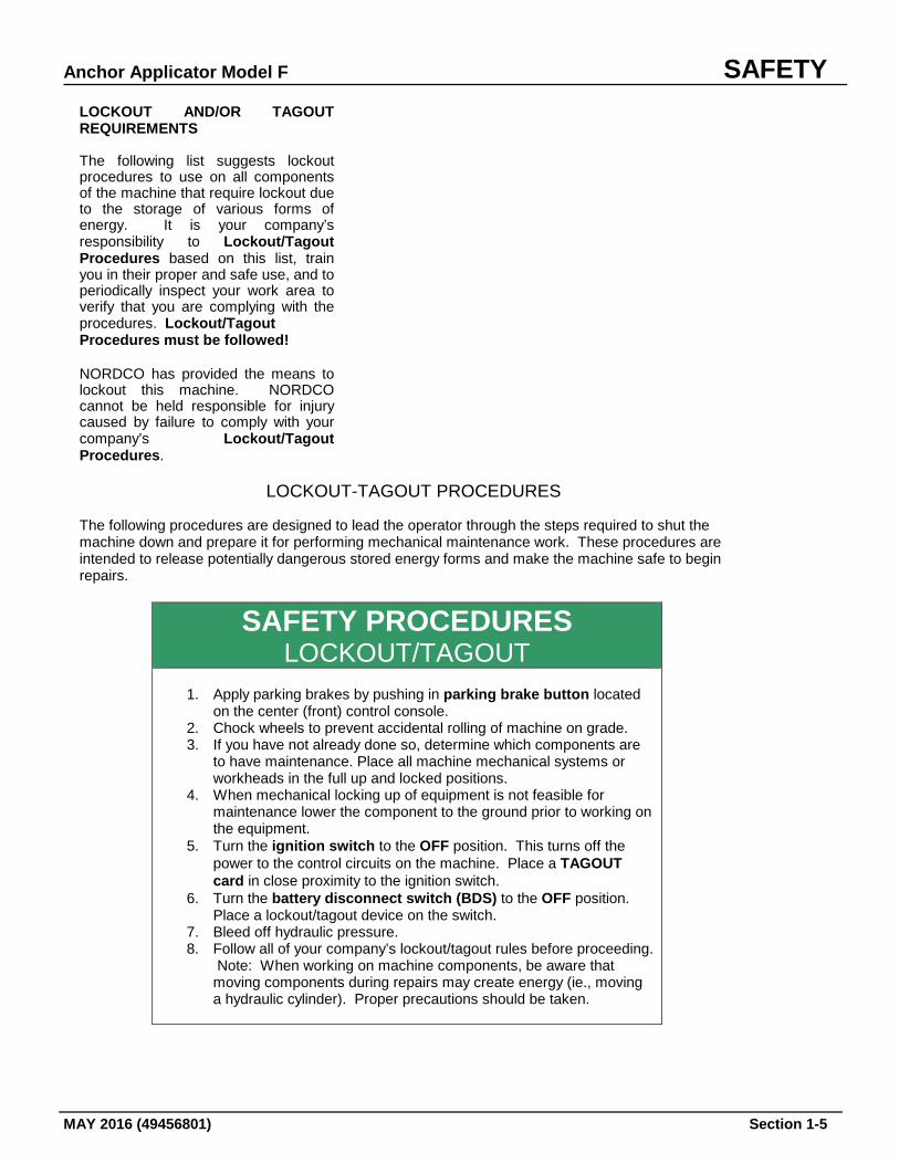
LOCKOUT-TAGOUT PROCEDURES The following procedures are designed to lead the operator through the steps required to shut the machine down and prepare it for performing mechanical maintenance work. These procedures are intended to release potentially dangerous stored energy forms and make the machine safe to begin repairs.
SAFETY PROCEDURES LOCKOUT/TAGOUT
1. Apply parking brakes by pushing in parking brake button located
on the center (front) control console. 2. Chock wheels to prevent accidental rolling of machine on grade. 3. If you have not already done so, determine which components are
to have maintenance. Place all machine mechanical systems or workheads in the full up and locked positions.
4. When mechanical locking up of equipment is not feasible for maintenance lower the component to the ground prior to working on the equipment.
5. Turn the ignition switch to the OFF position. This turns off the power to the control circuits on the machine. Place a TAGOUT card in close proximity to the ignition switch.
6. Turn the battery disconnect switch (BDS) to the OFF position. Place a lockout/tagout device on the switch.
7. Bleed off hydraulic pressure. 8. Follow all of your company’s lockout/tagout rules before proceeding.
Note: When working on machine components, be aware that moving components during repairs may create energy (ie., moving a hydraulic cylinder). Proper precautions should be taken.
SAFETY Anchor Applicator Model F
Section 1-6 MAY 2016 (49456801)
SAFETY DECALS ON THIS MACHINE Safety decals and plaques that have been placed on this machine are to be kept clean and legible. Replace any decals or plaques that have become illegible or are missing. When repairing or replacing components that had safety decals on them, it is your responsibility to replace the safety decals. These can be ordered from the Parts Sales Department. Safety Decals on this Machine are:
PART NO. DESCRIPTION LOCATION
5642 0001 General Machine Cautions Inside Cab 5642 0002 Caution! Watch Your Step Each stairway 5642 0004 Danger! Pinch Points On workhead 5642 0005 Warning! Hand Hazard On workhead 5642 0006 Danger! Before Servicing... Logic Box Sides 5642 4501 Caution! Before Welding... Logic Box Face
Battery Box 5642 0010 Lockout Area Logic Box Face 5642 0011 Lockout Area Battery Box 5642 0012 Lockup Points All areas requiring
Lockups for travel.
Anchor Applicator Model F GENERAL
MAY 2016 (49456801) Section 2-1
GENERAL
This manual contains operation and maintenance information for the Anchor Applicator Model “F” manufactured by NORDCO INC., Oak Creek, Wisconsin. Information regarding the operation and maintenance of this machine can be found behind the appropriate tabs. Information regarding operation and maintenance of OEM parts not of NORDCO manufacture can be found at the back of this manual, behind the tab marked Component Data. Become familiar with all safety instructions, controls and instruments before operating this machine. Follow all instructions carefully. ABOUT THIS MANUAL This manual has been broken down into sections which have been separated by index tabs. Behind each index tab is a blue colored section for troubleshooting the applicable section.
Mechanical has individual parts breakdown drawings and lists for each assembly Hydraulic includes adjustment instructions and troubleshooting for the hydraulic system; and all piping and functional drawings for a standard machine and optional equipment Electrical, includes all electrical schematics, logic box, control box, and cable drawings for the machine; and troubleshooting instructions Component Data includes parts breakdowns and service instructions for components installed on the machine that are not of NORDCO’s manufacture
GENERAL Anchor Applicator Model F
Section 2-2 MAY 2016 (49456801)
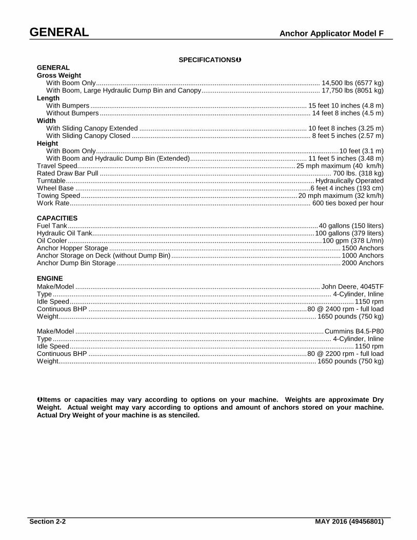
SPECIFICATIONS GENERAL Gross Weight With Boom Only ....................................................................................................................... 14,500 lbs (6577 kg) With Boom, Large Hydraulic Dump Bin and Canopy ............................................................... 17,750 lbs (8051 kg) Length With Bumpers ................................................................................................................... 15 feet 10 inches (4.8 m) Without Bumpers ................................................................................................................ 14 feet 8 inches (4.5 m) Width With Sliding Canopy Extended ......................................................................................... 10 feet 8 inches (3.25 m) With Sliding Canopy Closed ............................................................................................... 8 feet 5 inches (2.57 m) Height With Boom Only ................................................................................................................................. 10 feet (3.1 m) With Boom and Hydraulic Dump Bin (Extended) .............................................................. 11 feet 5 inches (3.48 m) Travel Speed.................................................................................................................... 25 mph maximum (40 km/h) Rated Draw Bar Pull ........................................................................................................................... 700 lbs. (318 kg) Turntable .................................................................................................................................... Hydraulically Operated Wheel Base .............................................................................................................................6 feet 4 inches (193 cm) Towing Speed ................................................................................................................... 20 mph maximum (32 km/h) Work Rate ................................................................................................................................ 600 ties boxed per hour CAPACITIES Fuel Tank ..................................................................................................................................... 40 gallons (150 liters) Hydraulic Oil Tank...................................................................................................................... 100 gallons (379 liters) Oil Cooler ....................................................................................................................................... 100 gpm (378 L/mn) Anchor Hopper Storage ........................................................................................................................... 1500 Anchors Anchor Storage on Deck (without Dump Bin) .......................................................................................... 1000 Anchors Anchor Dump Bin Storage ....................................................................................................................... 2000 Anchors ENGINE Make/Model .................................................................................................................................. John Deere, 4045TF Type .................................................................................................................................................... 4-Cylinder, Inline Idle Speed ....................................................................................................................................................... 1150 rpm Continuous BHP .................................................................................................................... 80 @ 2400 rpm - full load Weight ......................................................................................................................................... 1650 pounds (750 kg) Make/Model .................................................................................................................................... Cummins B4.5-P80 Type .................................................................................................................................................... 4-Cylinder, Inline Idle Speed ....................................................................................................................................................... 1150 rpm Continuous BHP .................................................................................................................... 80 @ 2200 rpm - full load Weight ......................................................................................................................................... 1650 pounds (750 kg) Items or capacities may vary according to options on your machine. Weights are approximate Dry Weight. Actual weight may vary according to options and amount of anchors stored on your machine. Actual Dry Weight of your machine is as stenciled.
Anchor Applicator Model F GENERAL
MAY 2016 (49456801) Section 2-3
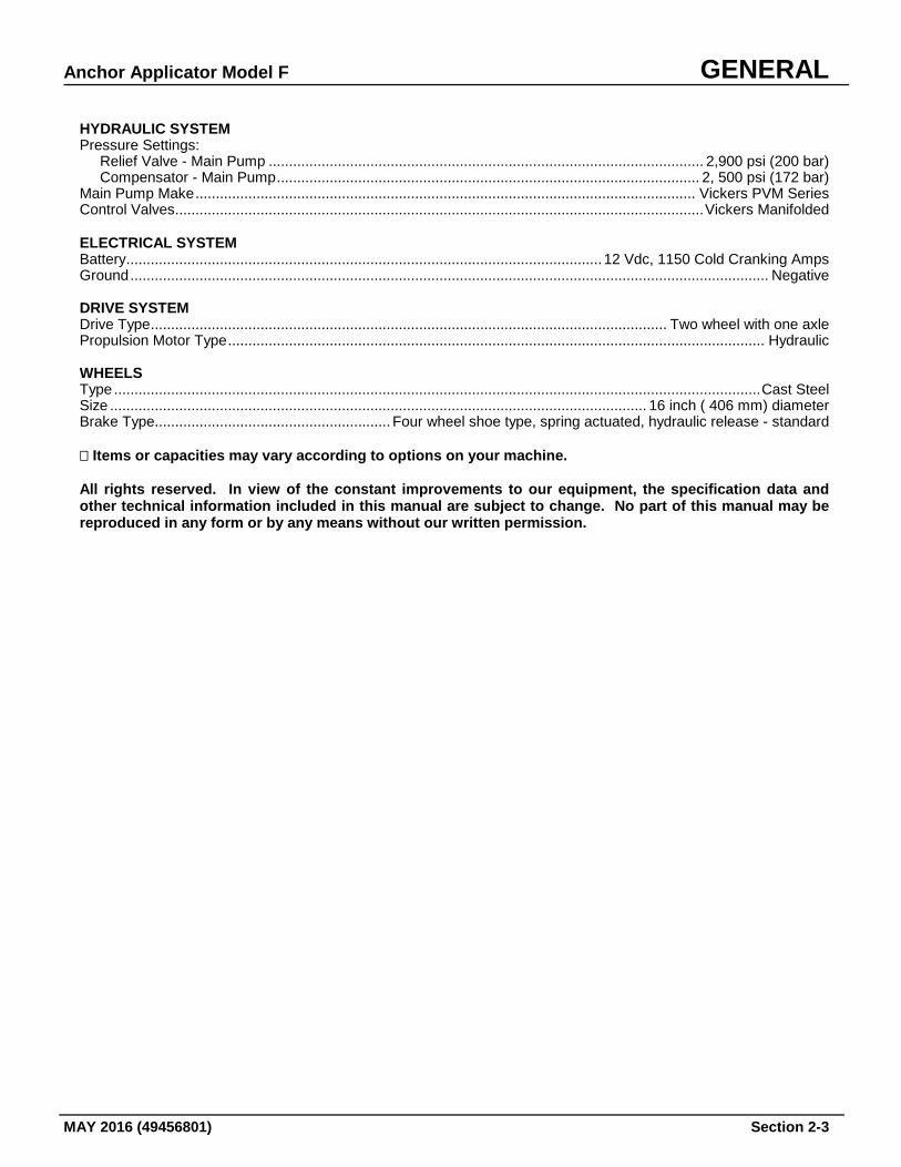
HYDRAULIC SYSTEM Pressure Settings: Relief Valve - Main Pump ........................................................................................................... 2,900 psi (200 bar) Compensator - Main Pump ........................................................................................................ 2, 500 psi (172 bar) Main Pump Make ........................................................................................................................... Vickers PVM Series Control Valves .................................................................................................................................. Vickers Manifolded ELECTRICAL SYSTEM Battery ..................................................................................................................... 12 Vdc, 1150 Cold Cranking Amps Ground ............................................................................................................................................................. Negative DRIVE SYSTEM Drive Type ............................................................................................................................... Two wheel with one axle Propulsion Motor Type .................................................................................................................................... Hydraulic WHEELS Type ............................................................................................................................................................... Cast Steel Size .................................................................................................................................... 16 inch ( 406 mm) diameter Brake Type.......................................................... Four wheel shoe type, spring actuated, hydraulic release - standard � Items or capacities may vary according to options on your machine. All rights reserved. In view of the constant improvements to our equipment, the specification data and other technical information included in this manual are subject to change. No part of this manual may be reproduced in any form or by any means without our written permission.

GENERAL Anchor Applicator Model F
Section 2-4 MAY 2016 (49456801)
--- Page Intentionally Left Blank --
Anchor Applicator Model F PRE-OPERATION/STARTUP
MAY 2016 (49456801) Section 3-1
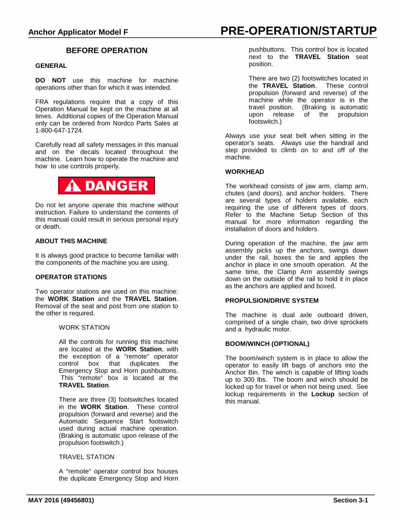
BEFORE OPERATION GENERAL DO NOT use this machine for machine operations other than for which it was intended. FRA regulations require that a copy of this Operation Manual be kept on the machine at all times. Additional copies of the Operation Manual only can be ordered from Nordco Parts Sales at 1-800-647-1724. Carefully read all safety messages in this manual and on the decals located throughout the machine. Learn how to operate the machine and how to use controls properly.
Do not let anyone operate this machine without instruction. Failure to understand the contents of this manual could result in serious personal injury or death. ABOUT THIS MACHINE It is always good practice to become familiar with the components of the machine you are using. OPERATOR STATIONS Two operator stations are used on this machine: the WORK Station and the TRAVEL Station. Removal of the seat and post from one station to the other is required.
WORK STATION
All the controls for running this machine are located at the WORK Station, with the exception of a “remote“ operator control box that duplicates the Emergency Stop and Horn pushbuttons. This “remote“ box is located at the TRAVEL Station.
There are three (3) footswitches located in the WORK Station. These control propulsion (forward and reverse) and the Automatic Sequence Start footswitch used during actual machine operation. (Braking is automatic upon release of the propulsion footswitch.)
TRAVEL STATION
A “remote“ operator control box houses the duplicate Emergency Stop and Horn
pushbuttons. This control box is located next to the TRAVEL Station seat position.
There are two (2) footswitches located in the TRAVEL Station. These control propulsion (forward and reverse) of the machine while the operator is in the travel position. (Braking is automatic upon release of the propulsion footswitch.)
Always use your seat belt when sitting in the operator’s seats. Always use the handrail and step provided to climb on to and off of the machine. WORKHEAD The workhead consists of jaw arm, clamp arm, chutes (and doors), and anchor holders. There are several types of holders available, each requiring the use of different types of doors. Refer to the Machine Setup Section of this manual for more information regarding the installation of doors and holders. During operation of the machine, the jaw arm assembly picks up the anchors, swings down under the rail, boxes the tie and applies the anchor in place in one smooth operation. At the same time, the Clamp Arm assembly swings down on the outside of the rail to hold it in place as the anchors are applied and boxed. PROPULSION/DRIVE SYSTEM The machine is dual axle outboard driven, comprised of a single chain, two drive sprockets and a hydraulic motor. BOOM/WINCH (OPTIONAL) The boom/winch system is in place to allow the operator to easily lift bags of anchors into the Anchor Bin. The winch is capable of lifting loads up to 300 lbs. The boom and winch should be locked up for travel or when not being used. See lockup requirements in the Lockup section of this manual.
PRE-OPERATION/STARTUP Anchor Applicator Model F
Section 3-2 MAY 2016 (49456801)
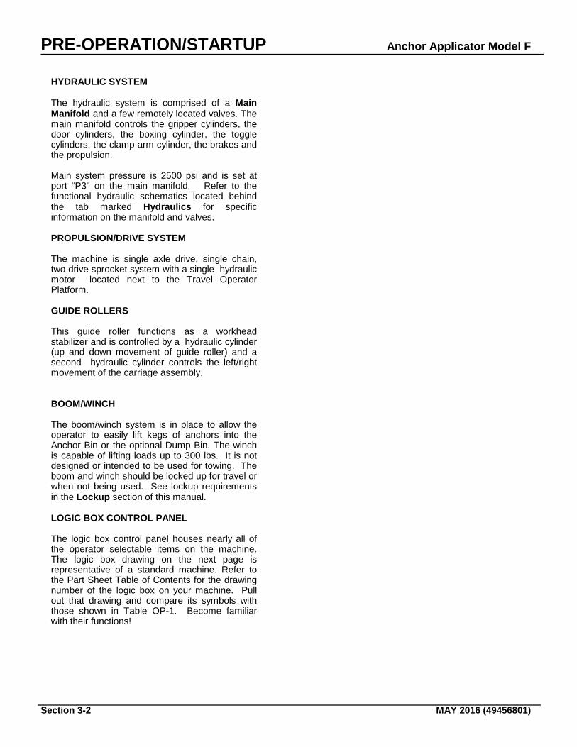
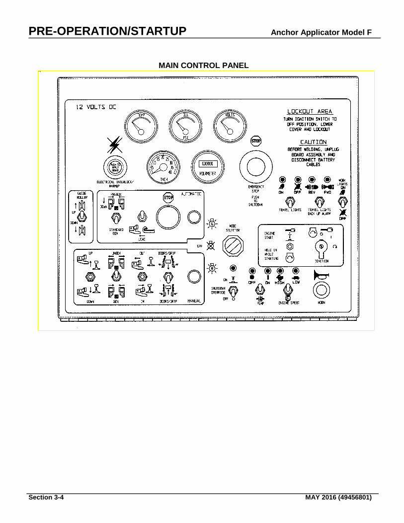
HYDRAULIC SYSTEM The hydraulic system is comprised of a Main Manifold and a few remotely located valves. The main manifold controls the gripper cylinders, the door cylinders, the boxing cylinder, the toggle cylinders, the clamp arm cylinder, the brakes and the propulsion. Main system pressure is 2500 psi and is set at port “P3" on the main manifold. Refer to the functional hydraulic schematics located behind the tab marked Hydraulics for specific information on the manifold and valves. PROPULSION/DRIVE SYSTEM The machine is single axle drive, single chain, two drive sprocket system with a single hydraulic motor located next to the Travel Operator Platform. GUIDE ROLLERS This guide roller functions as a workhead stabilizer and is controlled by a hydraulic cylinder (up and down movement of guide roller) and a second hydraulic cylinder controls the left/right movement of the carriage assembly. BOOM/WINCH The boom/winch system is in place to allow the operator to easily lift kegs of anchors into the Anchor Bin or the optional Dump Bin. The winch is capable of lifting loads up to 300 lbs. It is not designed or intended to be used for towing. The boom and winch should be locked up for travel or when not being used. See lockup requirements in the Lockup section of this manual. LOGIC BOX CONTROL PANEL The logic box control panel houses nearly all of the operator selectable items on the machine. The logic box drawing on the next page is representative of a standard machine. Refer to the Part Sheet Table of Contents for the drawing number of the logic box on your machine. Pull out that drawing and compare its symbols with those shown in Table OP-1. Become familiar with their functions!

Anchor Applicator Model F PRE-OPERATION/STARTUP
MAY 2016 (49456801) Section 3-3
THIS PAGE INTENTIONALLY LEFT BLANK
PRE-OPERATION/STARTUP Anchor Applicator Model F
Section 3-4 MAY 2016 (49456801)
MAIN CONTROL PANEL
Anchor Applicator Model F PRE-OPERATION/STARTUP
MAY 2016 (49456801) Section 3-5
Control or Instrument
Control Type
Function
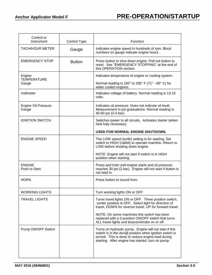
TACH/HOUR METER
Gauge
Indicates engine speed in hundreds of rpm. Block numbers on gauge indicate engine hours.
EMERGENCY STOP
Button
Press button to shut down engine. Pull out button to reset. See "EMERGENCY STOPPING" at the end of this OPERATION section.
Engine TEMPERATURE Gauge
Indicates temperature of engine or cooling system. Normal reading is 160° to 185° F (71° - 85° C) for water cooled engines.
Voltmeter
Indicates voltage of battery. Normal reading is 13-15 volts.
Engine Oil Pressure Gauge
Indicates oil pressure. Does not indicate oil level. Measurement in psi graduations. Normal reading is 40-60 psi (3-4 bar).
IGNITION SWITCH
Switches power to all circuits. Activates starter (when held fully clockwise). USED FOR NORMAL ENGINE SHUTDOWN.
ENGINE SPEED
The LOW speed (turtle) setting is for starting. Set switch to HIGH (rabbit) to operate machine. Return to LOW before shutting down engine. NOTE: Engine will not start if switch is in HIGH position when starting.
ENGINE Push to Start
Press and hold until engine starts and oil pressure reaches 30 psi (2 bar). Engine will not start if button is not held in.
HORN
Press button to sound horn.
WORKING LIGHTS
Turn working lights ON or OFF
TRAVEL LIGHTS
Turns travel lights ON or OFF. Three position switch, center position is OFF. Select light for direction of travel, DOWN for reverse travel, UP for forward travel. NOTE: On some machines this switch has been replaced with a 2-position ON/OFF switch that turns ALL travel lights and beacon/strobe on or off.
Pump ON/OFF Switch
Turns on hydraulic pump. Engine will not start if this switch is in the Aon@ position when ignition switch is turned. This is done to reduce engine load during starting. After engine has started, turn on pump.
PRE-OPERATION/STARTUP Anchor Applicator Model F
Section 3-6 MAY 2016 (49456801)
Control or Instrument
Control Type
Function
Mode Selector Switch
Used to select the desired operational mode (Auto or Manual), or to turn power OFF from the Manual Mode. For AUTO mode, the switch must be momentarily rotated to the right position. When properly rotated, the green pilot light on the Auto Control Panel will illuminate. To stop the auto mode, you must depress the Auto Stop push button on the Auto Control Panel. For MANUAL mode, the switch must be moved to the left position and kept there. When properly rotated, the red pilot light on the Manual Control Panel will illuminate. To stop the manual mode, you must move the Mode Selector Switch to the center position.
Park Switch (Electrical Interlock/Warmup)
When pushed in, disables all electrical input to the workheads. Also locks brakes. Should be used during machine warmup or inspection.
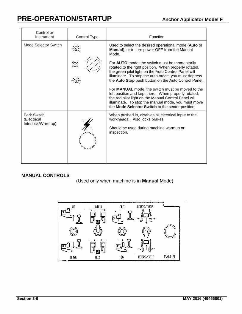
MANUAL CONTROLS (Used only when machine is in Manual Mode)
Anchor Applicator Model F PRE-OPERATION/STARTUP
MAY 2016 (49456801) Section 3-7
Control or Instrument
International Symbol
Function
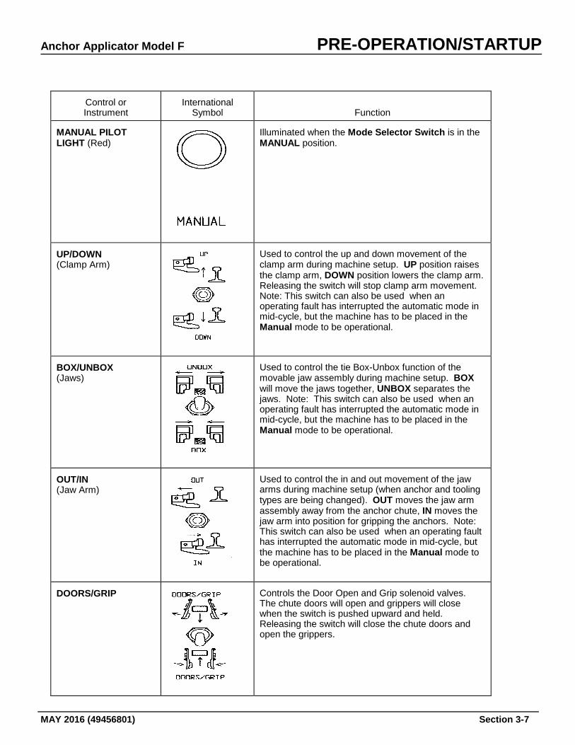
MANUAL PILOT LIGHT (Red)
Illuminated when the Mode Selector Switch is in the MANUAL position.
UP/DOWN (Clamp Arm)
Used to control the up and down movement of the clamp arm during machine setup. UP position raises the clamp arm, DOWN position lowers the clamp arm. Releasing the switch will stop clamp arm movement. Note: This switch can also be used when an operating fault has interrupted the automatic mode in mid-cycle, but the machine has to be placed in the Manual mode to be operational.
BOX/UNBOX (Jaws)
Used to control the tie Box-Unbox function of the movable jaw assembly during machine setup. BOX will move the jaws together, UNBOX separates the jaws. Note: This switch can also be used when an operating fault has interrupted the automatic mode in mid-cycle, but the machine has to be placed in the Manual mode to be operational.
OUT/IN (Jaw Arm)
Used to control the in and out movement of the jaw arms during machine setup (when anchor and tooling types are being changed). OUT moves the jaw arm assembly away from the anchor chute, IN moves the jaw arm into position for gripping the anchors. Note: This switch can also be used when an operating fault has interrupted the automatic mode in mid-cycle, but the machine has to be placed in the Manual mode to be operational.
DOORS/GRIP
Controls the Door Open and Grip solenoid valves. The chute doors will open and grippers will close when the switch is pushed upward and held. Releasing the switch will close the chute doors and open the grippers.
PRE-OPERATION/STARTUP Anchor Applicator Model F
Section 3-8 MAY 2016 (49456801)
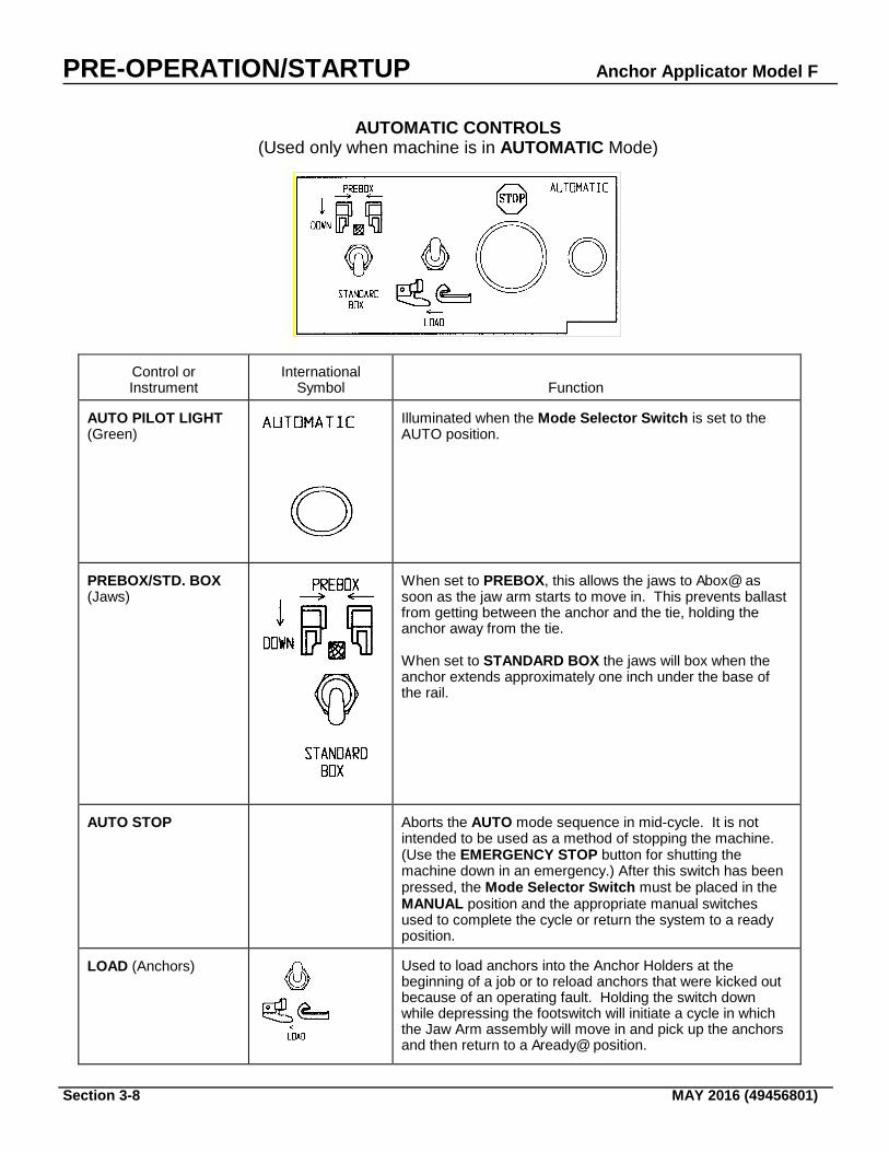
AUTOMATIC CONTROLS (Used only when machine is in AUTOMATIC Mode)
Control or Instrument
International Symbol
Function
AUTO PILOT LIGHT (Green)
Illuminated when the Mode Selector Switch is set to the AUTO position.
PREBOX/STD. BOX (Jaws)
When set to PREBOX, this allows the jaws to Abox@ as soon as the jaw arm starts to move in. This prevents ballast from getting between the anchor and the tie, holding the anchor away from the tie. When set to STANDARD BOX the jaws will box when the anchor extends approximately one inch under the base of the rail.
AUTO STOP
Aborts the AUTO mode sequence in mid-cycle. It is not intended to be used as a method of stopping the machine. (Use the EMERGENCY STOP button for shutting the machine down in an emergency.) After this switch has been pressed, the Mode Selector Switch must be placed in the MANUAL position and the appropriate manual switches used to complete the cycle or return the system to a ready position.
LOAD (Anchors)
Used to load anchors into the Anchor Holders at the beginning of a job or to reload anchors that were kicked out because of an operating fault. Holding the switch down while depressing the footswitch will initiate a cycle in which the Jaw Arm assembly will move in and pick up the anchors and then return to a Aready@ position.

Anchor Applicator Model F PRE-OPERATION/STARTUP
MAY 2016 (49456801) Section 3-9
REMOTE OPERATOR CONTROL BOX The Remote Operator Control Box shown below is all-inclusive and is for symbol reference purposes only. This configuration may not reflect the box that is on your machine.
TABLE OP-2 REMOTE OPERATOR CONTROL BOX
PRE-OPERATION/STARTUP Anchor Applicator Model F
Section 3-10 MAY 2016 (49456801)
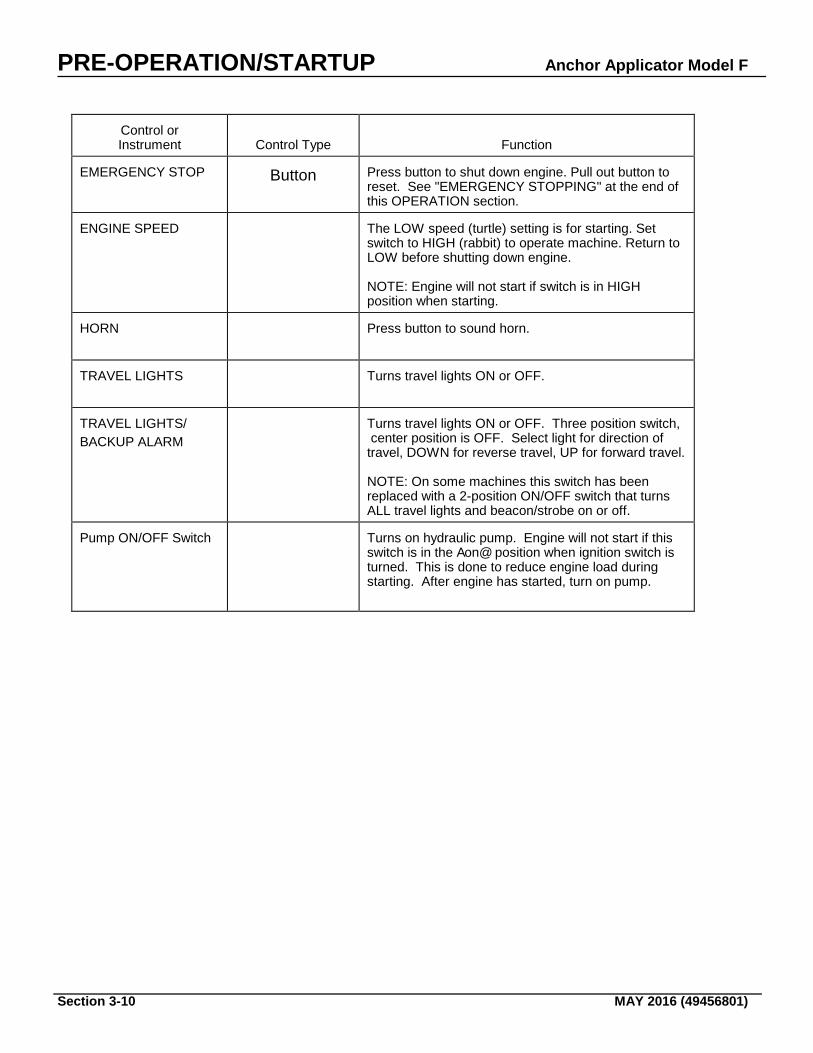
Control or Instrument
Control Type
Function
EMERGENCY STOP
Button
Press button to shut down engine. Pull out button to reset. See "EMERGENCY STOPPING" at the end of this OPERATION section.
ENGINE SPEED
The LOW speed (turtle) setting is for starting. Set switch to HIGH (rabbit) to operate machine. Return to LOW before shutting down engine. NOTE: Engine will not start if switch is in HIGH position when starting.
HORN
Press button to sound horn.
TRAVEL LIGHTS
Turns travel lights ON or OFF.
TRAVEL LIGHTS/ BACKUP ALARM
Turns travel lights ON or OFF. Three position switch, center position is OFF. Select light for direction of travel, DOWN for reverse travel, UP for forward travel. NOTE: On some machines this switch has been replaced with a 2-position ON/OFF switch that turns ALL travel lights and beacon/strobe on or off.
Pump ON/OFF Switch
Turns on hydraulic pump. Engine will not start if this switch is in the Aon@ position when ignition switch is turned. This is done to reduce engine load during starting. After engine has started, turn on pump.
Anchor Applicator Model F PRE-OPERATION/STARTUP
MAY 2016 (49456801) Section 3-11
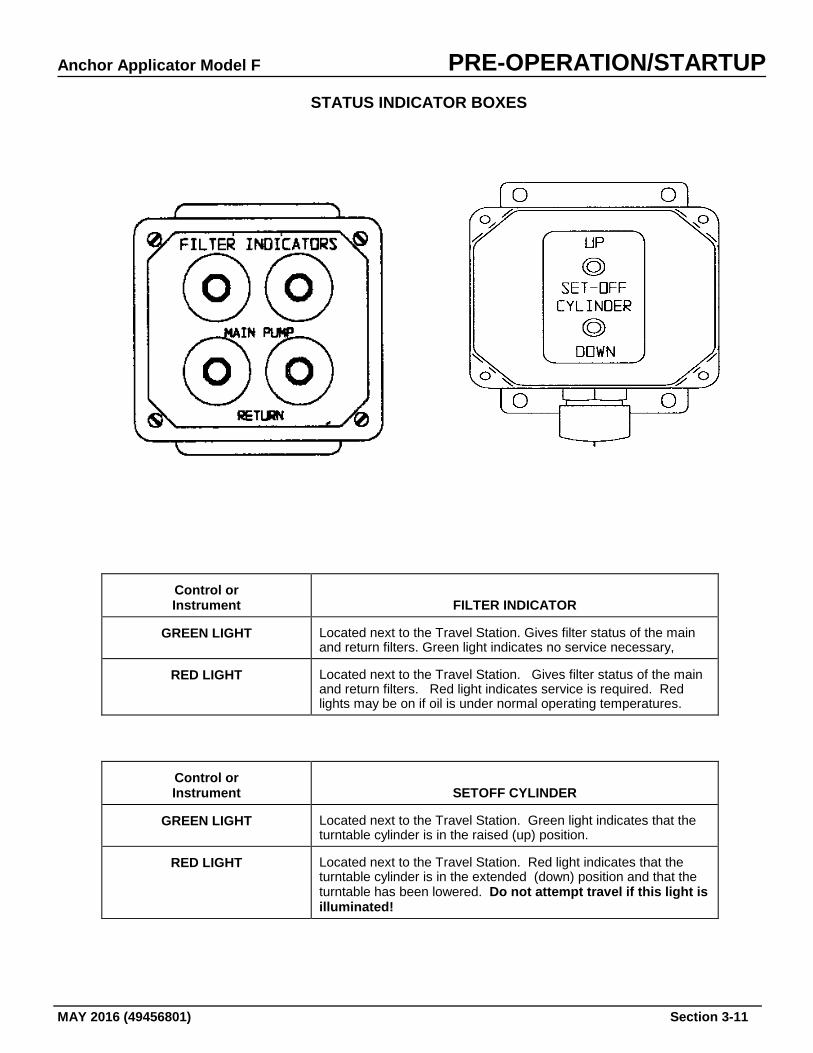
STATUS INDICATOR BOXES
Control or Instrument
FILTER INDICATOR
GREEN LIGHT
Located next to the Travel Station. Gives filter status of the main and return filters. Green light indicates no service necessary,
RED LIGHT
Located next to the Travel Station. Gives filter status of the main and return filters. Red light indicates service is required. Red lights may be on if oil is under normal operating temperatures.
Control or Instrument
SETOFF CYLINDER
GREEN LIGHT
Located next to the Travel Station. Green light indicates that the turntable cylinder is in the raised (up) position.
RED LIGHT
Located next to the Travel Station. Red light indicates that the turntable cylinder is in the extended (down) position and that the turntable has been lowered. Do not attempt travel if this light is illuminated!
PRE-OPERATION/STARTUP Anchor Applicator Model F
Section 3-12 MAY 2016 (49456801)
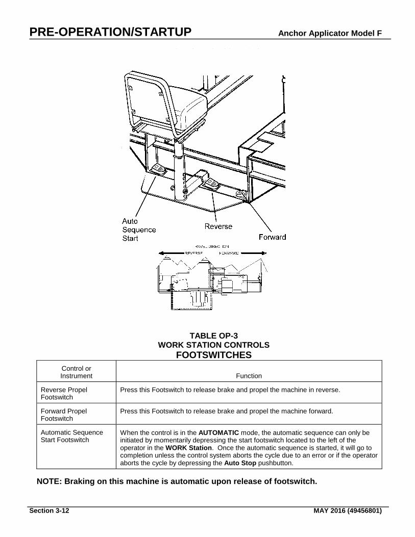
WORK STATION CONTROLS FOOTSWITCHES TABLE OP-3 WORK STATION CONTROLS FOOTSWITCHES
Control or Instrument
Function
Reverse Propel Footswitch
Press this Footswitch to release brake and propel the machine in reverse.
Forward Propel Footswitch
Press this Footswitch to release brake and propel the machine forward.
Automatic Sequence Start Footswitch
When the control is in the AUTOMATIC mode, the automatic sequence can only be initiated by momentarily depressing the start footswitch located to the left of the operator in the WORK Station. Once the automatic sequence is started, it will go to completion unless the control system aborts the cycle due to an error or if the operator aborts the cycle by depressing the Auto Stop pushbutton.
NOTE: Braking on this machine is automatic upon release of footswitch.
Anchor Applicator Model F PRE-OPERATION/STARTUP
MAY 2016 (49456801) Section 3-13
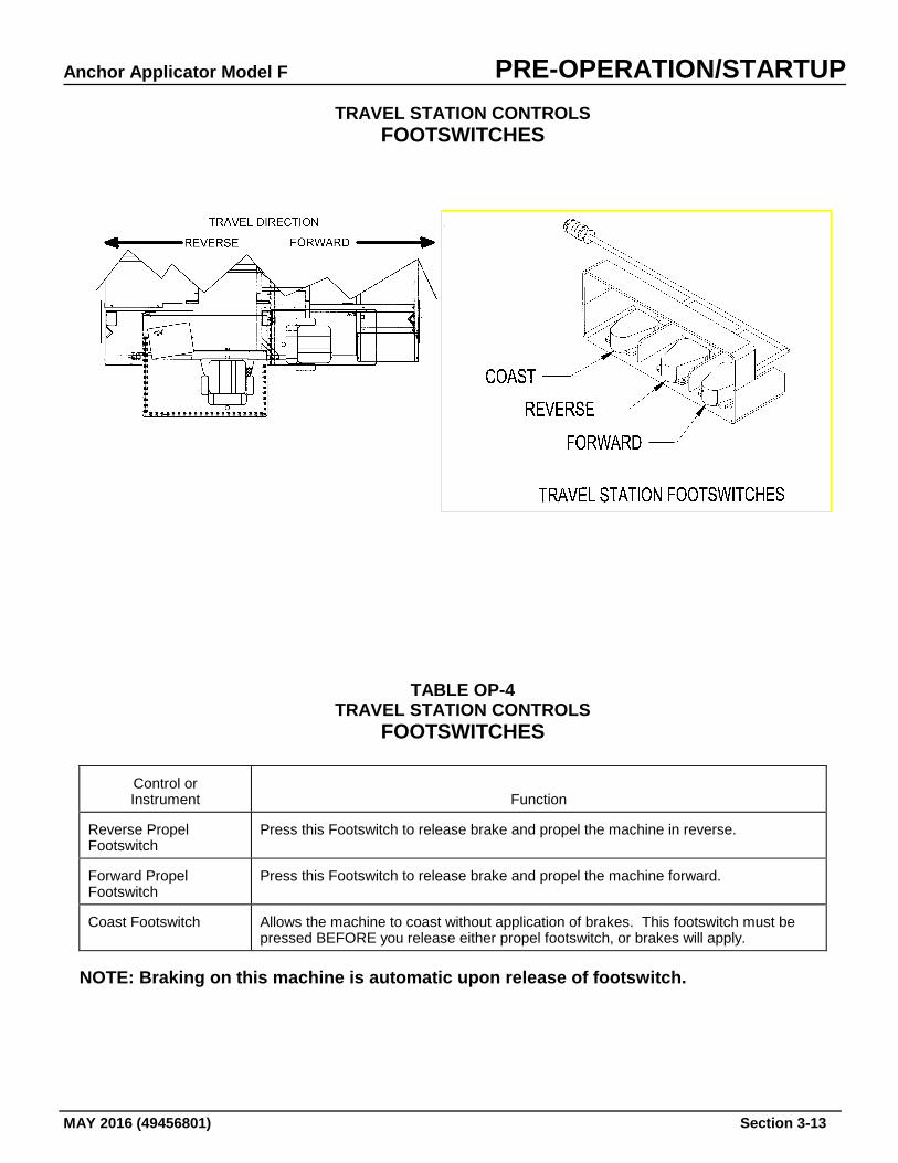
TRAVEL STATION CONTROLS FOOTSWITCHES
TABLE OP-4 TRAVEL STATION CONTROLS FOOTSWITCHES
Control or Instrument
Function
Reverse Propel Footswitch
Press this Footswitch to release brake and propel the machine in reverse.
Forward Propel Footswitch
Press this Footswitch to release brake and propel the machine forward.
Coast Footswitch
Allows the machine to coast without application of brakes. This footswitch must be pressed BEFORE you release either propel footswitch, or brakes will apply.
NOTE: Braking on this machine is automatic upon release of footswitch.
PRE-OPERATION/STARTUP Anchor Applicator Model F
Section 3-14 MAY 2016 (49456801)
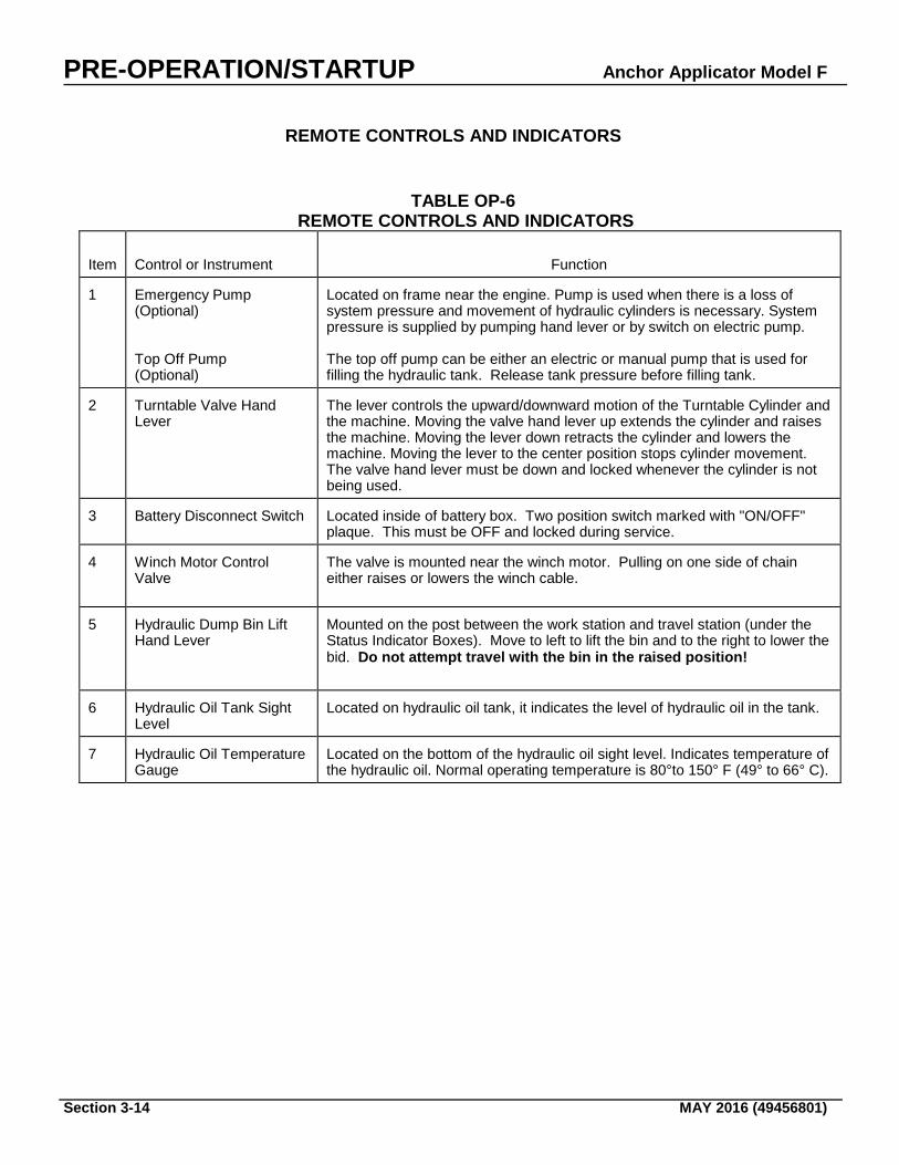
REMOTE CONTROLS AND INDICATORS
TABLE OP-6 REMOTE CONTROLS AND INDICATORS Item
Control or Instrument
Function
1
Emergency Pump (Optional) Top Off Pump (Optional)
Located on frame near the engine. Pump is used when there is a loss of system pressure and movement of hydraulic cylinders is necessary. System pressure is supplied by pumping hand lever or by switch on electric pump. The top off pump can be either an electric or manual pump that is used for filling the hydraulic tank. Release tank pressure before filling tank.
2
Turntable Valve Hand Lever
The lever controls the upward/downward motion of the Turntable Cylinder and the machine. Moving the valve hand lever up extends the cylinder and raises the machine. Moving the lever down retracts the cylinder and lowers the machine. Moving the lever to the center position stops cylinder movement. The valve hand lever must be down and locked whenever the cylinder is not being used.
3
Battery Disconnect Switch
Located inside of battery box. Two position switch marked with "ON/OFF" plaque. This must be OFF and locked during service.
4
Winch Motor Control Valve
The valve is mounted near the winch motor. Pulling on one side of chain either raises or lowers the winch cable.
5
Hydraulic Dump Bin Lift Hand Lever
Mounted on the post between the work station and travel station (under the Status Indicator Boxes). Move to left to lift the bin and to the right to lower the bid. Do not attempt travel with the bin in the raised position!
6
Hydraulic Oil Tank Sight Level
Located on hydraulic oil tank, it indicates the level of hydraulic oil in the tank.
7
Hydraulic Oil Temperature Gauge
Located on the bottom of the hydraulic oil sight level. Indicates temperature of the hydraulic oil. Normal operating temperature is 80°to 150° F (49° to 66° C).
Anchor Applicator Model F PRE-OPERATION/STARTUP
MAY 2016 (49456801) Section 3-15
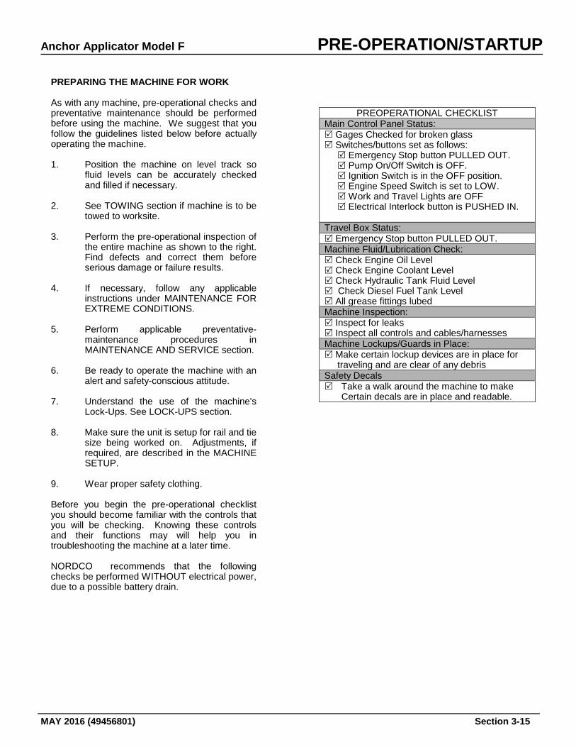
PREPARING THE MACHINE FOR WORK As with any machine, pre-operational checks and preventative maintenance should be performed before using the machine. We suggest that you follow the guidelines listed below before actually operating the machine. 1. Position the machine on level track so
fluid levels can be accurately checked and filled if necessary.
2. See TOWING section if machine is to be
towed to worksite. 3. Perform the pre-operational inspection of
the entire machine as shown to the right. Find defects and correct them before serious damage or failure results.
4. If necessary, follow any applicable
instructions under MAINTENANCE FOR EXTREME CONDITIONS.
5. Perform applicable preventative-
maintenance procedures in MAINTENANCE AND SERVICE section.
6. Be ready to operate the machine with an
alert and safety-conscious attitude. 7. Understand the use of the machine's
Lock-Ups. See LOCK-UPS section. 8. Make sure the unit is setup for rail and tie
size being worked on. Adjustments, if required, are described in the MACHINE SETUP.
9. Wear proper safety clothing. Before you begin the pre-operational checklist you should become familiar with the controls that you will be checking. Knowing these controls and their functions may will help you in troubleshooting the machine at a later time. NORDCO recommends that the following checks be performed WITHOUT electrical power, due to a possible battery drain.
PREOPERATIONAL CHECKLIST Main Control Panel Status: Gages Checked for broken glass Switches/buttons set as follows: Emergency Stop button PULLED OUT. Pump On/Off Switch is OFF. Ignition Switch is in the OFF position. Engine Speed Switch is set to LOW. Work and Travel Lights are OFF Electrical Interlock button is PUSHED IN. Travel Box Status: Emergency Stop button PULLED OUT. Machine Fluid/Lubrication Check: Check Engine Oil Level Check Engine Coolant Level Check Hydraulic Tank Fluid Level Check Diesel Fuel Tank Level All grease fittings lubed Machine Inspection: Inspect for leaks Inspect all controls and cables/harnesses Machine Lockups/Guards in Place: Make certain lockup devices are in place for traveling and are clear of any debris Safety Decals Take a walk around the machine to make
Certain decals are in place and readable.
PRE-OPERATION/STARTUP Anchor Applicator Model F
Section 3-16 MAY 2016 (49456801)
Engine Operation
Before starting a new or overhauled
engine that has been in storage, consult the engine manual for initial start instruction.
Failure to follow those instructions can result in serious engine damage.
Exhaust emissions caused by the
use of this machine may cause cancer, birth defects or other reproductive harm
If inhaled. NOTE: Avoid unnecessary idling. 1. Ensure the suction strainer valve on the
hydraulic oil tank is open and the Battery Disconnect Switch is ON.
2. Make certain EMERGENCY STOP
pushbuttons on both the main control panel and workhead control box have been pulled out. Set engine speed switch to LOW and pump switch to OFF. NOTE: Engine will not start if the engine speed switch is set to HIGH.
1. Hold the Magnetic Override switch (MO)
(labeled ENGINE/PUSH TO START) in and turn the ignition switch to the right until the engine starts. Release the ignition switch (will spring back to centered position) and continue holding the MO switch until oil pressure reaches 30 psi (2 bar or 207 kPa). Allow 5-7 minutes of warmup if first start of the day.
If the machine is equipped with glow plugs, push and hold the momentary push button for 15 seconds prior to cranking the engine. NOTE: Engine will not start if engine speed switch is in HIGH position, emergency stop pushbuttons are pushed in, if the MO is not held in, or if pump switch is ON.
2. If the engine fails to start within 30 seconds, allow the starting motor to cool a few minutes before trying again.
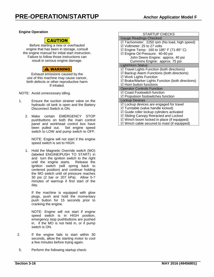
5. Perform the following startup check:
STARTUP CHECKS Gauge Readings Checked: Tachometer: 2250 rpm (No load, high speed) Voltmeter: 25 to 27 volts Engine Temp: 160 to 185° F (71-85° C) Engine Oil Pressure: 40-60 psi John Deere Engine: approx. 40 psi Cummins Engine: approx. 75 psi Light/Horn Status: Travel Lights Function (both directions) Backup Alarm Functions (both directions) Work Lights Function Brake/Marker Lights Function (both directions) Horn button functions Operator Controls Function Coast Footswitch function Propulsion footswitches function Lockup Devices Lockup devices are engaged for travel Turntable (valve handle locked) Guide roller lockup cylinders activated Sliding Canopy Retracted and Locked Winch boom locked in place (if equipped) Winch cable secured to mast (if equipped)
Anchor Applicator Model F PRE-OPERATION/STARTUP
MAY 2016 (49456801) Section 3-17
LOCK-UPS
Failure to engage all lockup devices before propelling at travel speed can result in injury to personnel and/or damage to the machine.
These are required to be in the locked up position prior to working travel through crossings, switches or other rail obstructions or during high speed travel (non-working travel). See next page for details on when lockups are to be used. Use the following procedures to install or remove lock-ups. Clamp Arm Lock Located on the frame floor to the left and right of the Clamp Arms. This lock is used to secure the Clamp Arm in the UP position for traveling. Use the following procedure to lock the clamp arms:
1. Put mode selector switch in the MANUAL position. (Red LED will illuminate, indicating machine is in manual mode.)
2. Raise the Clamp Arm by holding the Clamp Arm UP/DOWN Switch in the UP position.
3. Insert lockpin. Note: Removal of the lockup may require use of Step #2 to take the weight of the assembly off of the lockup pin. UGuide Wheel Lockpin U
Used to lock the rail guide wheel in the UP position. There are two (2) guide wheel assemblies on this machine. The first is located on the flooring between the TRAVEL Station and the Dump Bin, the second is located next to the hydraulic tank on the operator side of the machine. To install the lockpin:
1. Manually raise the guide wheel assembly until a hole appears.
2. Insert pin into hole. Set-Off Cylinder Lockup To make certain that the turntable cannot be lowered without your knowledge, lock up the turntable control valve lever in the down position (only way it can be locked). Some machines are equipped with Status Indicator Boxes that will show the status of the setoff cylinder, whether up (green light) or down (red light).
Dump Bin Lockups The hydraulic dump bin allows this machine to carry additional anchors. It was not designed to be in the raised position during working operations, except to dump more anchors into the primary bin. The dump bin should be in the locked UP position to 1) prevent the bin from drifting down when adding anchors, and 2) during maintenance when access to the hydraulic cylinder is needed. Boom and Winch Lock-ups The optional boom assembly has a boom interlock handle that enables the operators to unlock the boom to move the assembly over the track. When the interlock handle is pulled down and rotated until the roll pin is in its seated, locked position, the boom has free swing movement. When locking up the boom, pull the interlock handle down and rotate it until the roll pin is free from its seated position. Release the handle. Swing the boom so that it is parallel with the track and the spring loaded pin engages the lock-up hole. Sliding Canopy The sliding canopy interlock handle enables the operators to unlock the sliding canopy from the main canopy and pull it out and over the operator from When the interlock handle is pulled down and rotated until the roll pin is in its seated, locked position, the boom has free swing movement. When locking up the boom, pull the interlock handle down and rotate it until the roll pin is free from its seated position. Release the handle. Swing the boom so that it is parallel with the track and the spring loaded pin engages the lock-up hole.
PRE-OPERATION/STARTUP Anchor Applicator Model F
Section 3-18 MAY 2016 (49456801)
TABLE OP-9. LOCK-UPS
Lock-up
LOCATION
TOTAL
WHEN USED
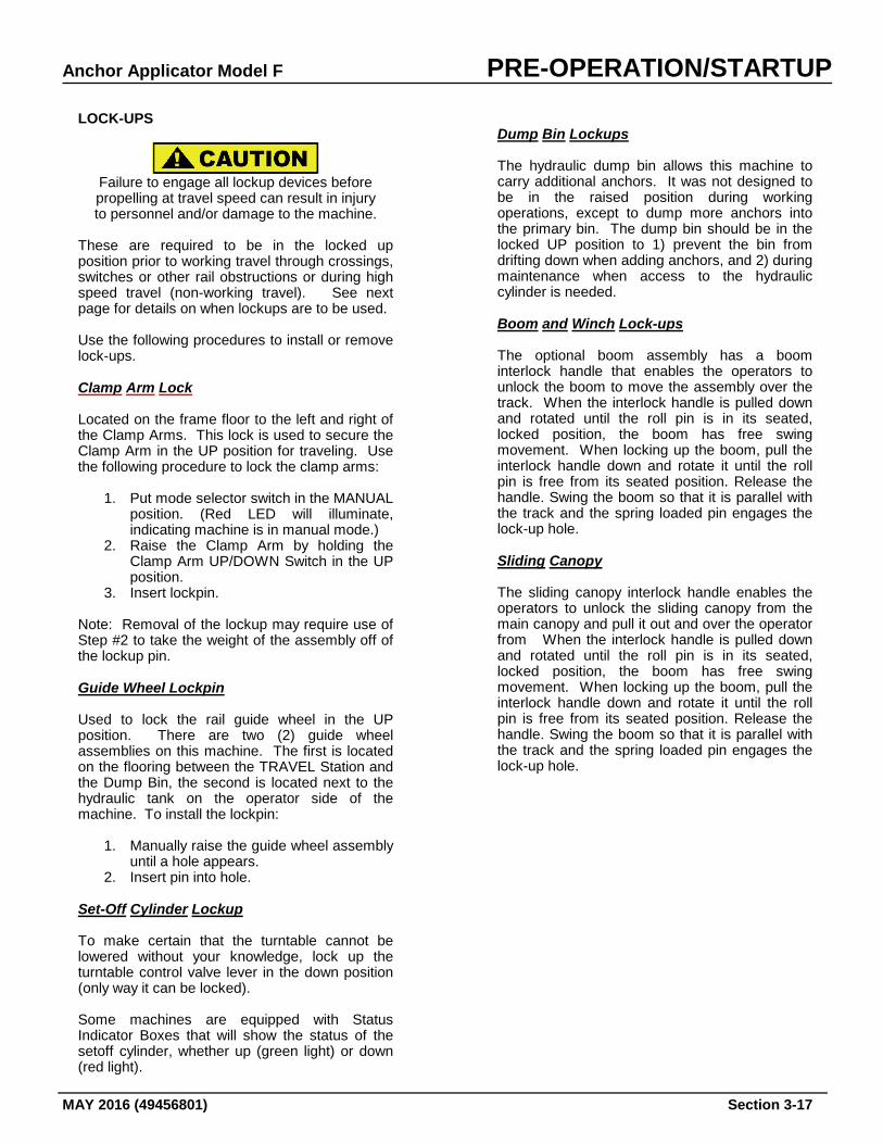
Clamp Arm
To the right or left of the Clamp Arm.
2
During working travel through crossings, at switches, frogs, and other rail obstructions, and during high speed (non-working) travel. Note: Clamp Arm must be fully raised for lock pin to be inserted.
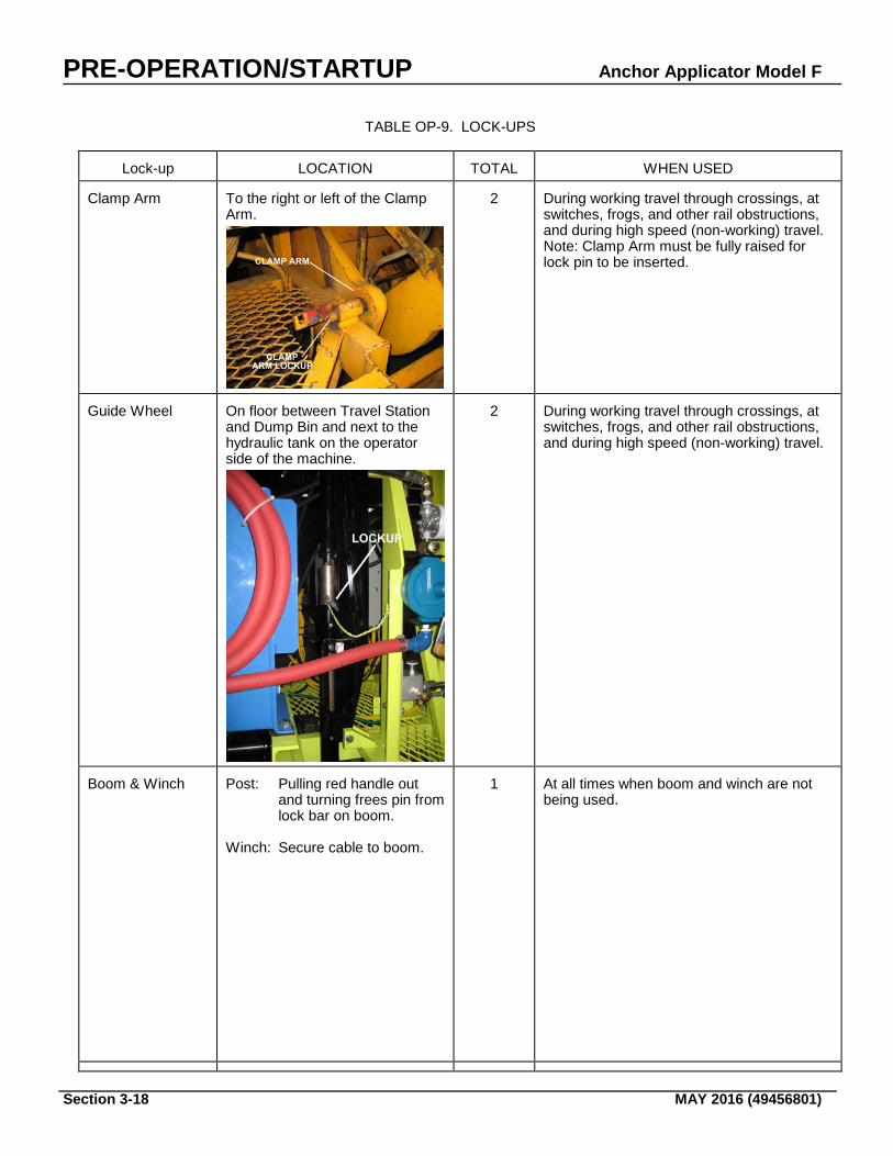
Guide Wheel
On floor between Travel Station and Dump Bin and next to the hydraulic tank on the operator side of the machine.
2
During working travel through crossings, at switches, frogs, and other rail obstructions, and during high speed (non-working) travel.
Boom & Winch
Post: Pulling red handle out
and turning frees pin from lock bar on boom.
Winch: Secure cable to boom.
1
At all times when boom and winch are not being used.
Anchor Applicator Model F PRE-OPERATION/STARTUP
MAY 2016 (49456801) Section 3-19
Lock-up
LOCATION
TOTAL
WHEN USED
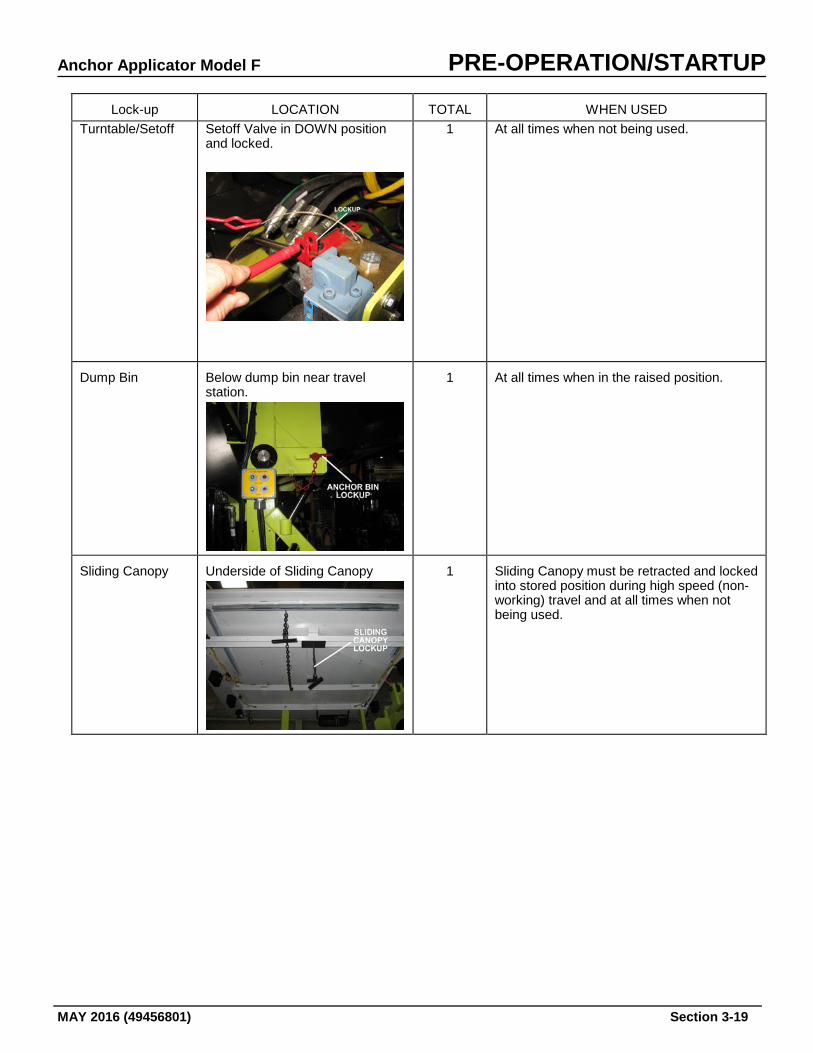
Turntable/Setoff Setoff Valve in DOWN position and locked.
1 At all times when not being used.
Dump Bin
Below dump bin near travel station.
1
At all times when in the raised position.
Sliding Canopy
Underside of Sliding Canopy
1
Sliding Canopy must be retracted and locked into stored position during high speed (non-working) travel and at all times when not being used.
PRE-OPERATION/SETUP Anchor Applicator Model F
Section 3-20 MAY 2016 (49456801)
TRAVEL It is important that you read about and understand all operating controls, Cautions, Warnings, and Dangers before traveling.
Do not permit unauthorized personnel to ride on
the decks outside the cab. Falling from a moving Vehicle will cause serious injury or death.
Make certain that the area around and under
The machine is clear of all personnel and obstructions before traveling or working.
Failure to do so will cause serious injury or death.
ENGINE SPEEDS Engine speed is controlled by the switch on the Main Control Panel. Engine speed settings are slow and fast. When idling, the switch should be set to LOW, for traveling or work operations, you should have the engine speed switch in the HIGH position. PROPELLING AND BRAKING Before traveling (either in work or travel modes) determine the method of braking and set the controls to either “deadman”
(brakes automatically apply upon release of propulsion pedal) or “service”
(brakes are applied only when brake pedal is applied).
Propelling for Non-Working Travel 1. Put the machine in the TRAVEL position. 2. Make certain that all lockups are engaged. 3. Put the Propel Speed switch in the HIGH
(2X) position. 4. Press the appropriate foot switch to propel
the machine. Propelling for Working Travel 1. Put the machine in the WORK position. 2. All lockups should be unlocked – with the
exception of the turntable lockup. 3. Put the Propel Speed switch in the LOW (4X)
position. 4. Press the appropriate footswitch to propel the
machine.
Propelling on Steep Grades (Work or Travel)
Switching from 2X to 4X while traveling at speeds
in excess of 10 mph will result in dynamic braking, which may cause bodily injury.
1. Put the machine in the TRAVEL position. 2. Put the Propel Speed switch in the LOW (4X)
position. 3. Make certain that brakes function properly. 4. Press the appropriate foot switch to propel
the machine.
Anchor Applicator Model F PRE-OPERATION/SETUP
MAY 2016 (49456801) Section 3-21
Machine Setup Instructions in this section are provided for changing the type of anchors to be used and for making adjustments to the machine to compensate for different rail sizes. Some of these procedures will be required as part of the scheduled routine maintenance and are referenced on the maintenance chart located in the Maintenance and Service section of this manual. Read and understand all OPERATION procedures, warnings, and cautions before making adjustments.
Serious injury or death can result from reaching into working components while machine is running. Make all observations from a distance and SHUT OFF machine while making adjustments.
Always turn off machine when performing maintenance, making adjustments, or whenever unintended movement of machine could occur; unless directed otherwise. Failure to comply could result in severe personal injury and/or damage to the machine. NOTE: All adjustments in this section require the machine to be in the MANUAL mode of operation. CHANGING ANCHOR TYPE Each time a different type of anchor is to be used, compatible anchor holders and chute doors must also be installed and adjusted. (Chute door adjustments are given later in this section.) Refer to the table on the next page for specific components for each type of anchor. To change anchor types: 1. Start engine and put Mode Selector
Switch in the MANUAL position.
2. Use Clamp Arm Up/Down Switch to raise clamp arm and install clamp arm lock pin.
3. Use Jaw Arm In/Out Switch to move
jaw arm out. 4. Turn ignition key switch to OFF and
remove keys. 5. Remove spring post nuts and spring
from each door. 6. Remove hinge pins and doors. 7. Disconnect hydraulic line from holder at
quick disconnect (located at frame about two feet from holders on hydraulic line on each side of anchor bin).
8. Remove hairpin cotters, holder pins, and
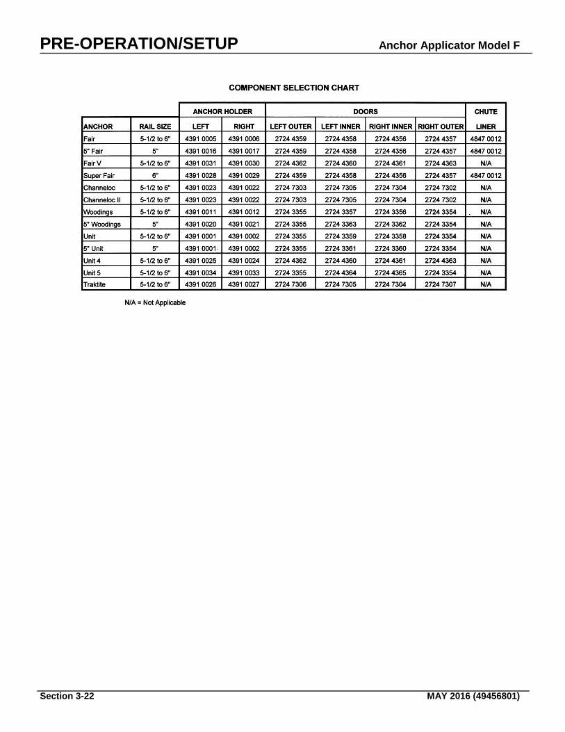
anchor holders. 9. Select type of anchor components to be
used for the job (i.e., Fair, Channeloc, Woodings, Unit, etc.). The table on the next page calls out the component part numbers for each type of anchor and must be followed to determine the right and left hand parts. The part number for each component is cast into each part.
Note: The hinge pin, tool holder pin, the door spring and the spring post nuts are standard parts and can be used with all anchor conversions.
10. Install each anchor holder into position
on the sliding jaws. Align holes and secure with holder pin and hairpin cotter.
11. Connect hydraulic lines to anchor holders
at quick disconnects. 12. Install appropriate doors, as specifed in
the table on the next page, and secure with hinge pins.
13. Install the end loops of each spring over
the spring posts at each doors and secure with post nuts.
14. Each time tooling is changed for a
different type of anchor, chute adjustments must be made to accommodate the new anchors. Proceed to CHUTE ADJUSTMENTS before attempting to operate the machine.
PRE-OPERATION/SETUP Anchor Applicator Model F
Section 3-22 MAY 2016 (49456801)
Anchor Applicator Model F PRE-OPERATION/SETUP
MAY 2016 (49456801) Section 3-23
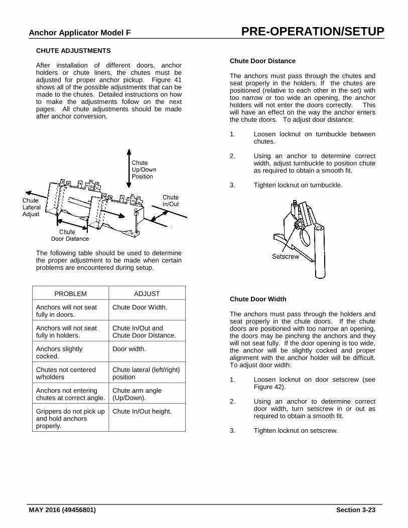
CHUTE ADJUSTMENTS After installation of different doors, anchor holders or chute liners, the chutes must be adjusted for proper anchor pickup. Figure 41 shows all of the possible adjustments that can be made to the chutes. Detailed instructions on how to make the adjustments follow on the next pages. All chute adjustments should be made after anchor conversion.
The following table should be used to determine the proper adjustment to be made when certain problems are encountered during setup.
PROBLEM
ADJUST
Anchors will not seat fully in doors.
Chute Door Width.
Anchors will not seat fully in holders.
Chute In/Out and Chute Door Distance.
Anchors slightly cocked.
Door width.
Chutes not centered w/holders
Chute lateral (left/right) position
Anchors not entering chutes at correct angle.
Chute arm angle (Up/Down).
Grippers do not pick up and hold anchors properly.
Chute In/Out height.
Chute Door Distance The anchors must pass through the chutes and seat properly in the holders. If the chutes are positioned (relative to each other in the set) with too narrow or too wide an opening, the anchor holders will not enter the doors correctly. This will have an effect on the way the anchor enters the chute doors. To adjust door distance: 1. Loosen locknut on turnbuckle between
chutes.
2. Using an anchor to determine correct width, adjust turnbuckle to position chute as required to obtain a smooth fit.
3. Tighten locknut on turnbuckle.
Chute Door Width The anchors must pass through the holders and seat properly in the chute doors. If the chute doors are positioned with too narrow an opening, the doors may be pinching the anchors and they will not seat fully. If the door opening is too wide, the anchor will be slightly cocked and proper alignment with the anchor holder will be difficult. To adjust door width: 1. Loosen locknut on door setscrew (see
Figure 42).
2. Using an anchor to determine correct door width, turn setscrew in or out as required to obtain a smooth fit.
3. Tighten locknut on setscrew.
PRE-OPERATION/SETUP Anchor Applicator Model F
Section 3-24 MAY 2016 (49456801)
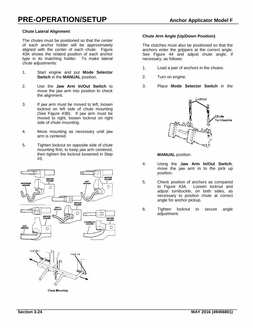
Chute Lateral Alignment The chutes must be positioned so that the center of each anchor holder will be approximately aligned with the center of each chute. Figure 43A shows the related position of each anchor type in its matching holder. To make lateral chute adjustments: 1. Start engine and put Mode Selector
Switch in the MANUAL position.
2. Use the Jaw Arm In/Out Switch to move the jaw arm into position to check the alignment.
3. If jaw arm must be moved to left, loosen locknut on left side of chute mounting (See Figure 43B). If jaw arm must be moved to right, loosen locknut on right side of chute mounting.
4. Move mounting as necessary until jaw
arm is centered. 5. Tighten locknut on opposite side of chute
mounting first, to keep jaw arm centered, then tighten the locknut loosened in Step #3.
Chute Arm Angle (Up/Down Position) The clutches must also be positioned so that the anchors enter the grippers at the correct angle. See Figure 44 and adjust chute angle, if necessary, as follows: 1. Load a pair of anchors in the chutes.
2. Turn on engine.
3. Place Mode Selector Switch in the
MANUAL position.
4. Using the Jaw Arm In/Out Switch, move the jaw arm in to the pick up position.
5. Check position of anchors as compared to Figure 43A. Loosen locknut and adjust turnbuckle, on both sides, as necessary to position chute at correct angle for anchor pickup.
6. Tighten locknut to secure angle adjustment.
Anchor Applicator Model F PRE-OPERATION/SETUP
MAY 2016 (49456801) Section 3-25
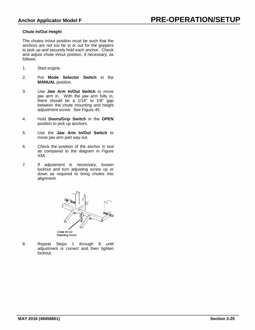
Chute In/Out Height The chutes in/out position must be such that the anchors are not too far in or out for the grippers to pick up and securely hold each anchor. Check and adjust chute in/out position, if necessary, as follows: 1. Start engine.
2. Put Mode Selector Switch in the
MANUAL position.
3. Use Jaw Arm In/Out Switch to move jaw arm in. With the jaw arm fully in, there should be a 1/16" to 1/8" gap between the chute mounting and height adjustment screw. See Figure 45.
4. Hold Doors/Grip Switch in the OPEN
position to pick up anchors. 5. Use the Jaw Arm In/Out Switch to
move jaw arm part way out. 6. Check the position of the anchor in tool
as compared to the diagram in Figure 43A.
7. If adjustment is necessary, loosen
locknut and turn adjusting screw up or down as required to bring chutes into alignment.
8. Repeat Steps 1 through 8 until adjustment is correct and then tighten locknut.
PRE-OPERATION/SETUP Anchor Applicator Model F
Section 3-26 MAY 2016 (49456801)
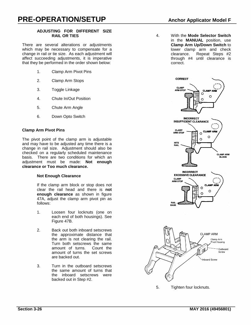
ADJUSTING FOR DIFFERENT SIZE RAIL OR TIES
There are several alterations or adjustments which may be necessary to compensate for a change in rail or tie size. As each adjustment will affect succeeding adjustments, it is imperative that they be performed in the order shown below:
1. Clamp Arm Pivot Pins
2. Clamp Arm Stops
3. Toggle Linkage
4. Chute In/Out Position
5. Chute Arm Angle
6. Down Opto Switch Clamp Arm Pivot Pins The pivot point of the clamp arm is adjustable and may have to be adjusted any time there is a change in rail size. Adjustment should also be checked on a regularly scheduled maintenance basis. There are two conditions for which an adjustment must be made: Not enough clearance or Too much clearance.
Not Enough Clearance
If the clamp arm block or stop does not clear the rail head and there is not enough clearance as shown in figure 47A, adjust the clamp arm pivot pin as follows:
1. Loosen four locknuts (one on
each end of both housings). See Figure 47B.
2. Back out both inboard setscrews
the approximate distance that the arm is not clearing the rail. Turn both setscrews the same amount of turns. Count the amount of turns the set screws are backed out.
3. Turn in the outboard setscrews
the same amount of turns that the inboard setscrews were backed out in Step #2.
4. With the Mode Selector Switch
in the MANUAL position, use Clamp Arm Up/Down Switch to lower clamp arm and check clearance. Repeat Steps #2 through #4 until clearance is correct.
5. Tighten four locknuts.
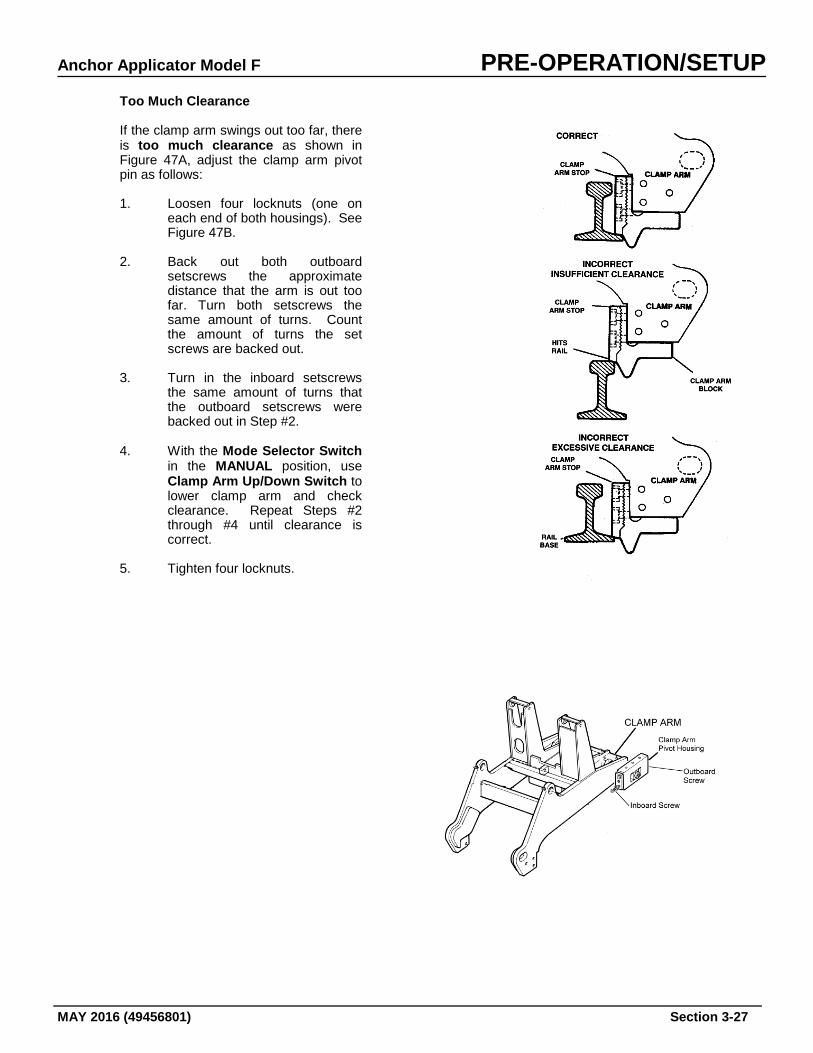
Anchor Applicator Model F PRE-OPERATION/SETUP
MAY 2016 (49456801) Section 3-27
Too Much Clearance
If the clamp arm swings out too far, there is too much clearance as shown in Figure 47A, adjust the clamp arm pivot pin as follows:
1. Loosen four locknuts (one on
each end of both housings). See Figure 47B.
2. Back out both outboard
setscrews the approximate distance that the arm is out too far. Turn both setscrews the same amount of turns. Count the amount of turns the set screws are backed out.
3. Turn in the inboard setscrews
the same amount of turns that the outboard setscrews were backed out in Step #2.
4. With the Mode Selector Switch
in the MANUAL position, use Clamp Arm Up/Down Switch to lower clamp arm and check clearance. Repeat Steps #2 through #4 until clearance is correct.
5. Tighten four locknuts.
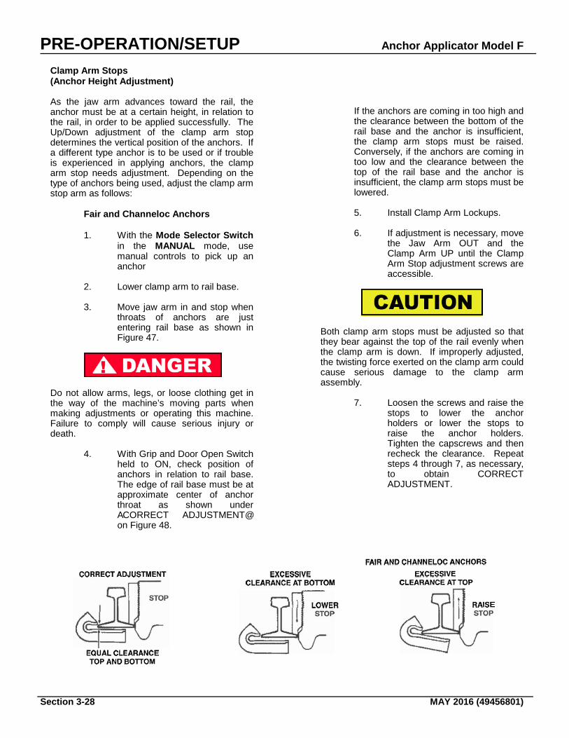
PRE-OPERATION/SETUP Anchor Applicator Model F
Section 3-28 MAY 2016 (49456801)
Clamp Arm Stops (Anchor Height Adjustment) As the jaw arm advances toward the rail, the anchor must be at a certain height, in relation to the rail, in order to be applied successfully. The Up/Down adjustment of the clamp arm stop determines the vertical position of the anchors. If a different type anchor is to be used or if trouble is experienced in applying anchors, the clamp arm stop needs adjustment. Depending on the type of anchors being used, adjust the clamp arm stop arm as follows:
Fair and Channeloc Anchors
1. With the Mode Selector Switch in the MANUAL mode, use manual controls to pick up an anchor
2. Lower clamp arm to rail base.
3. Move jaw arm in and stop when
throats of anchors are just entering rail base as shown in Figure 47.
Do not allow arms, legs, or loose clothing get in the way of the machine’s moving parts when making adjustments or operating this machine. Failure to comply will cause serious injury or death.
4. With Grip and Door Open Switch
held to ON, check position of anchors in relation to rail base. The edge of rail base must be at approximate center of anchor throat as shown under ACORRECT ADJUSTMENT@ on Figure 48.
If the anchors are coming in too high and the clearance between the bottom of the rail base and the anchor is insufficient, the clamp arm stops must be raised. Conversely, if the anchors are coming in too low and the clearance between the top of the rail base and the anchor is insufficient, the clamp arm stops must be lowered. 5. Install Clamp Arm Lockups.
6. If adjustment is necessary, move
the Jaw Arm OUT and the Clamp Arm UP until the Clamp Arm Stop adjustment screws are accessible.
Both clamp arm stops must be adjusted so that they bear against the top of the rail evenly when the clamp arm is down. If improperly adjusted, the twisting force exerted on the clamp arm could cause serious damage to the clamp arm assembly.
7. Loosen the screws and raise the stops to lower the anchor holders or lower the stops to raise the anchor holders. Tighten the capscrews and then recheck the clearance. Repeat steps 4 through 7, as necessary, to obtain CORRECT ADJUSTMENT.
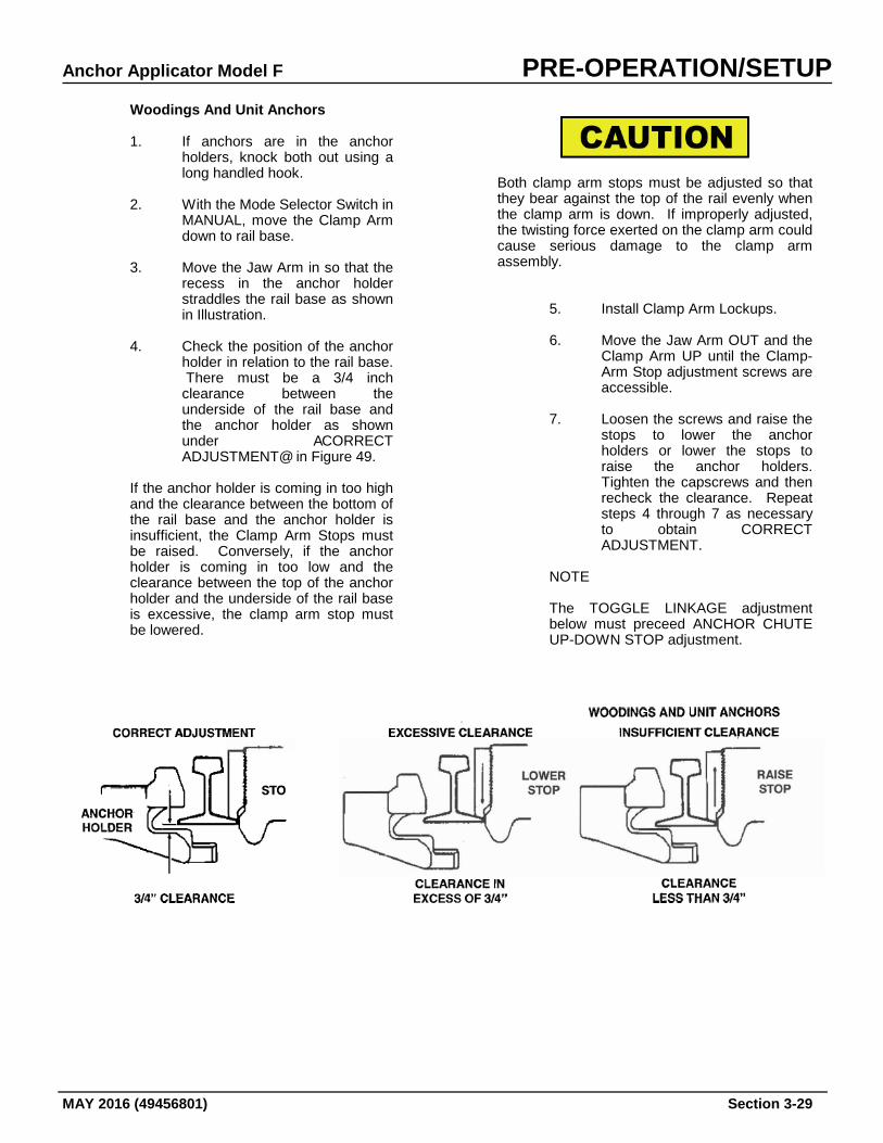
Anchor Applicator Model F PRE-OPERATION/SETUP
MAY 2016 (49456801) Section 3-29
Woodings And Unit Anchors
1. If anchors are in the anchor holders, knock both out using a long handled hook.
2. With the Mode Selector Switch in
MANUAL, move the Clamp Arm down to rail base.
3. Move the Jaw Arm in so that the
recess in the anchor holder straddles the rail base as shown in Illustration.
4. Check the position of the anchor
holder in relation to the rail base. There must be a 3/4 inch clearance between the underside of the rail base and the anchor holder as shown under ACORRECT ADJUSTMENT@ in Figure 49.
If the anchor holder is coming in too high and the clearance between the bottom of the rail base and the anchor holder is insufficient, the Clamp Arm Stops must be raised. Conversely, if the anchor holder is coming in too low and the clearance between the top of the anchor holder and the underside of the rail base is excessive, the clamp arm stop must be lowered.
Both clamp arm stops must be adjusted so that they bear against the top of the rail evenly when the clamp arm is down. If improperly adjusted, the twisting force exerted on the clamp arm could cause serious damage to the clamp arm assembly.
5. Install Clamp Arm Lockups.
6. Move the Jaw Arm OUT and the Clamp Arm UP until the Clamp-Arm Stop adjustment screws are accessible.
7. Loosen the screws and raise the
stops to lower the anchor holders or lower the stops to raise the anchor holders. Tighten the capscrews and then recheck the clearance. Repeat steps 4 through 7 as necessary to obtain CORRECT ADJUSTMENT.
NOTE
The TOGGLE LINKAGE adjustment below must preceed ANCHOR CHUTE UP-DOWN STOP adjustment.

PRE-OPERATION/SETUP Anchor Applicator Model F
Section 3-30 MAY 2016 (49456801)
Toggle Linkage The Toggle Linkage must be adjusted anytime different rail widths are encountered. Adjustment of the Toggle Linkage is based on the fact that the Driving Cylinders must be at the end of their stroke when anchors are fully applied. Refer to Figure 50 and adjust toggle linkage as follows: 1. Apply a set of anchors using the
MANUAL mode (see MANUAL OPERATION). But, release the Jaw Arm IN-OUT switch as soon as anchors are fully applied or the piston rods are fully extended.
2. Measure the rod stroke ON BOTH
CYLINDERS.
a. If the piston rod extends 9-5/8” and the anchor is fully applied without being over driven, the linkage is adjusted correctly.
b. If the piston rod is less than 9-
5/8", the toggle linkage must be shortened. This will lengthen the piston rod stroke.
c. If the piston rod is fully extended
but the anchor is short of application, the toggle linkage must be lengthened.
d. If the piston rod is fully extended
but the anchor is overdriven, (loose or broken), the toggle linkage must be shortened.
Make adjustment certain adjustment is correct on both arms to prevent twisting damage to the jaw arm assembly. 3. Remove Lock Pin and adjust toggle
linkage, if necessary, as follows:
a. Turn Toggle Turnbuckle CW to lengthen toggle linkage; or
b. Turn toggle Turnbuckle CCW to
shorten toggle linkage.
NOTE One Aflat@ rotation of turnbuckle will adjust length approximately 0.028 inch. 4. Install Lock Pin to secure adjustment. 5. Apply a set of anchors and recheck
length of piston stroke to make sure it is 9-5/8 inch when anchors are fully applied.
Anchor Chute Up-down Stop After the toggle linkage has been adjusted you must re-adjust the Chute In/Out Position. Refer to Chute Adjustments earlier in this manual for instructions on how to adjust the Chute In/Out Position. Chute Arm Angle After adjusting the chute Up/Down Stop described above, it may be necessary to also adjust the chute arm angle. Use the MANUAL mode to pick up a set of anchors. If the anchors are not staying in the holders, adjust the angle as described under Chute Adjustments earlier in this section.
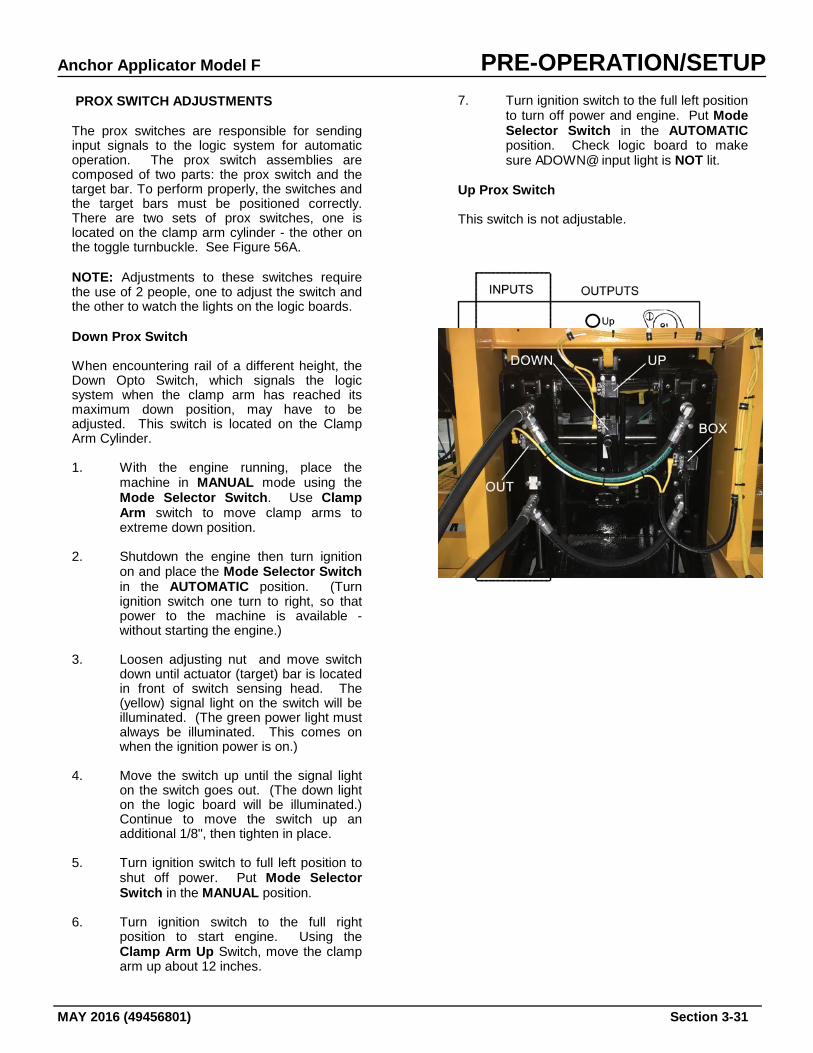
Anchor Applicator Model F PRE-OPERATION/SETUP
MAY 2016 (49456801) Section 3-31
PROX SWITCH ADJUSTMENTS The prox switches are responsible for sending input signals to the logic system for automatic operation. The prox switch assemblies are composed of two parts: the prox switch and the target bar. To perform properly, the switches and the target bars must be positioned correctly. There are two sets of prox switches, one is located on the clamp arm cylinder - the other on the toggle turnbuckle. See Figure 56A. NOTE: Adjustments to these switches require the use of 2 people, one to adjust the switch and the other to watch the lights on the logic boards. Down Prox Switch When encountering rail of a different height, the Down Opto Switch, which signals the logic system when the clamp arm has reached its maximum down position, may have to be adjusted. This switch is located on the Clamp Arm Cylinder. 1. With the engine running, place the
machine in MANUAL mode using the Mode Selector Switch. Use Clamp Arm switch to move clamp arms to extreme down position.
2. Shutdown the engine then turn ignition
on and place the Mode Selector Switch in the AUTOMATIC position. (Turn ignition switch one turn to right, so that power to the machine is available - without starting the engine.)
3. Loosen adjusting nut and move switch
down until actuator (target) bar is located in front of switch sensing head. The (yellow) signal light on the switch will be illuminated. (The green power light must always be illuminated. This comes on when the ignition power is on.)
4. Move the switch up until the signal light
on the switch goes out. (The down light on the logic board will be illuminated.) Continue to move the switch up an additional 1/8", then tighten in place.
5. Turn ignition switch to full left position to
shut off power. Put Mode Selector Switch in the MANUAL position.
6. Turn ignition switch to the full right
position to start engine. Using the Clamp Arm Up Switch, move the clamp arm up about 12 inches.
7. Turn ignition switch to the full left position to turn off power and engine. Put Mode Selector Switch in the AUTOMATIC position. Check logic board to make sure ADOWN@ input light is NOT lit.
Up Prox Switch This switch is not adjustable.
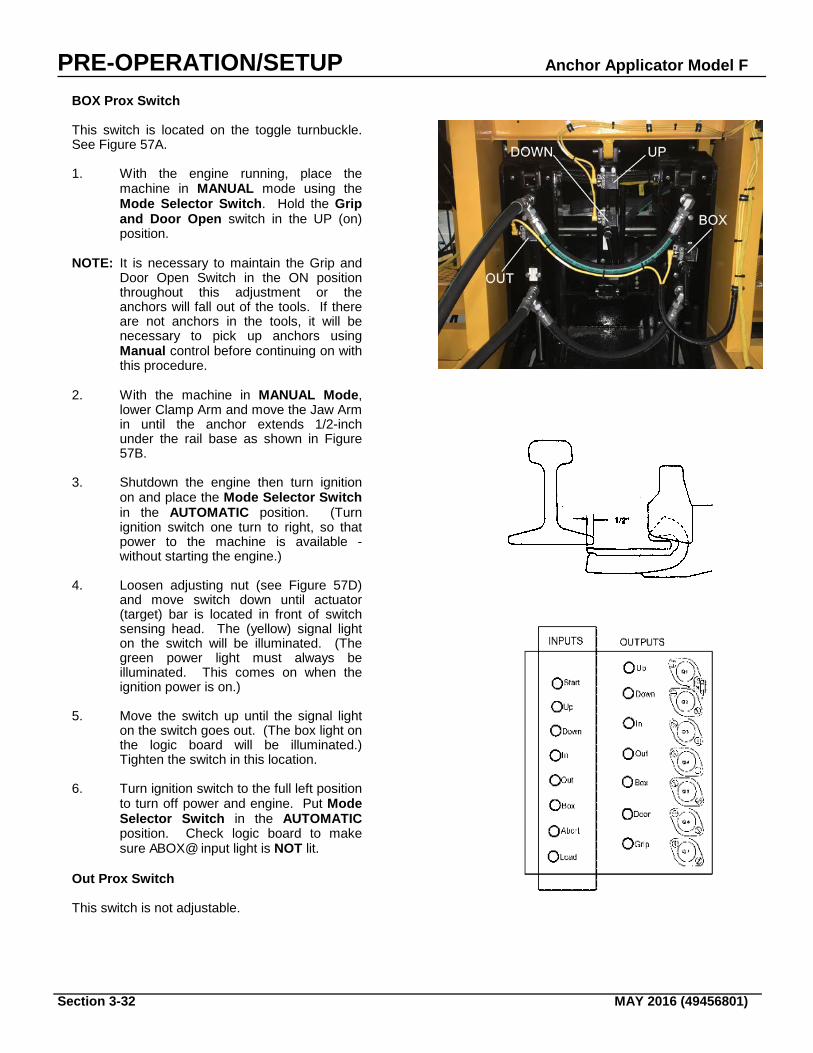
PRE-OPERATION/SETUP Anchor Applicator Model F
Section 3-32 MAY 2016 (49456801)
BOX Prox Switch This switch is located on the toggle turnbuckle. See Figure 57A. 1. With the engine running, place the
machine in MANUAL mode using the Mode Selector Switch. Hold the Grip and Door Open switch in the UP (on) position.
NOTE: It is necessary to maintain the Grip and
Door Open Switch in the ON position throughout this adjustment or the anchors will fall out of the tools. If there are not anchors in the tools, it will be necessary to pick up anchors using Manual control before continuing on with this procedure.
2. With the machine in MANUAL Mode,
lower Clamp Arm and move the Jaw Arm in until the anchor extends 1/2-inch under the rail base as shown in Figure 57B.
3. Shutdown the engine then turn ignition
on and place the Mode Selector Switch in the AUTOMATIC position. (Turn ignition switch one turn to right, so that power to the machine is available - without starting the engine.)
4. Loosen adjusting nut (see Figure 57D)
and move switch down until actuator (target) bar is located in front of switch sensing head. The (yellow) signal light on the switch will be illuminated. (The green power light must always be illuminated. This comes on when the ignition power is on.)
5. Move the switch up until the signal light
on the switch goes out. (The box light on the logic board will be illuminated.) Tighten the switch in this location.
6. Turn ignition switch to the full left position
to turn off power and engine. Put Mode Selector Switch in the AUTOMATIC position. Check logic board to make sure ABOX@ input light is NOT lit.
Out Prox Switch This switch is not adjustable.
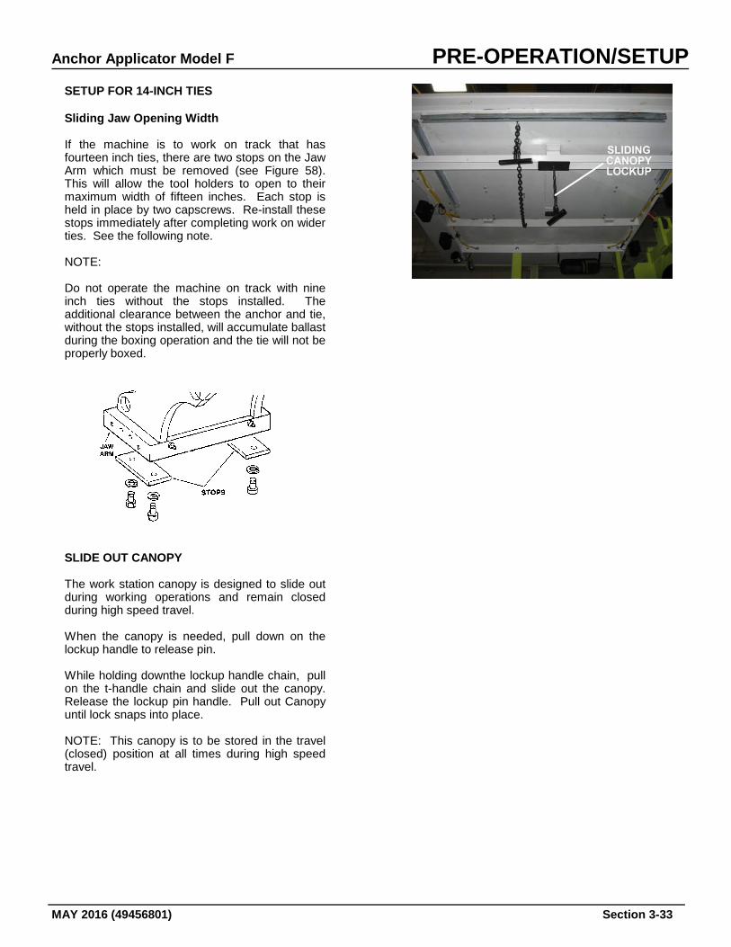
Anchor Applicator Model F PRE-OPERATION/SETUP
MAY 2016 (49456801) Section 3-33
SETUP FOR 14-INCH TIES Sliding Jaw Opening Width If the machine is to work on track that has fourteen inch ties, there are two stops on the Jaw Arm which must be removed (see Figure 58). This will allow the tool holders to open to their maximum width of fifteen inches. Each stop is held in place by two capscrews. Re-install these stops immediately after completing work on wider ties. See the following note. NOTE: Do not operate the machine on track with nine inch ties without the stops installed. The additional clearance between the anchor and tie, without the stops installed, will accumulate ballast during the boxing operation and the tie will not be properly boxed.
SLIDE OUT CANOPY The work station canopy is designed to slide out during working operations and remain closed during high speed travel. When the canopy is needed, pull down on the lockup handle to release pin. While holding downthe lockup handle chain, pull on the t-handle chain and slide out the canopy. Release the lockup pin handle. Pull out Canopy until lock snaps into place. NOTE: This canopy is to be stored in the travel (closed) position at all times during high speed travel.
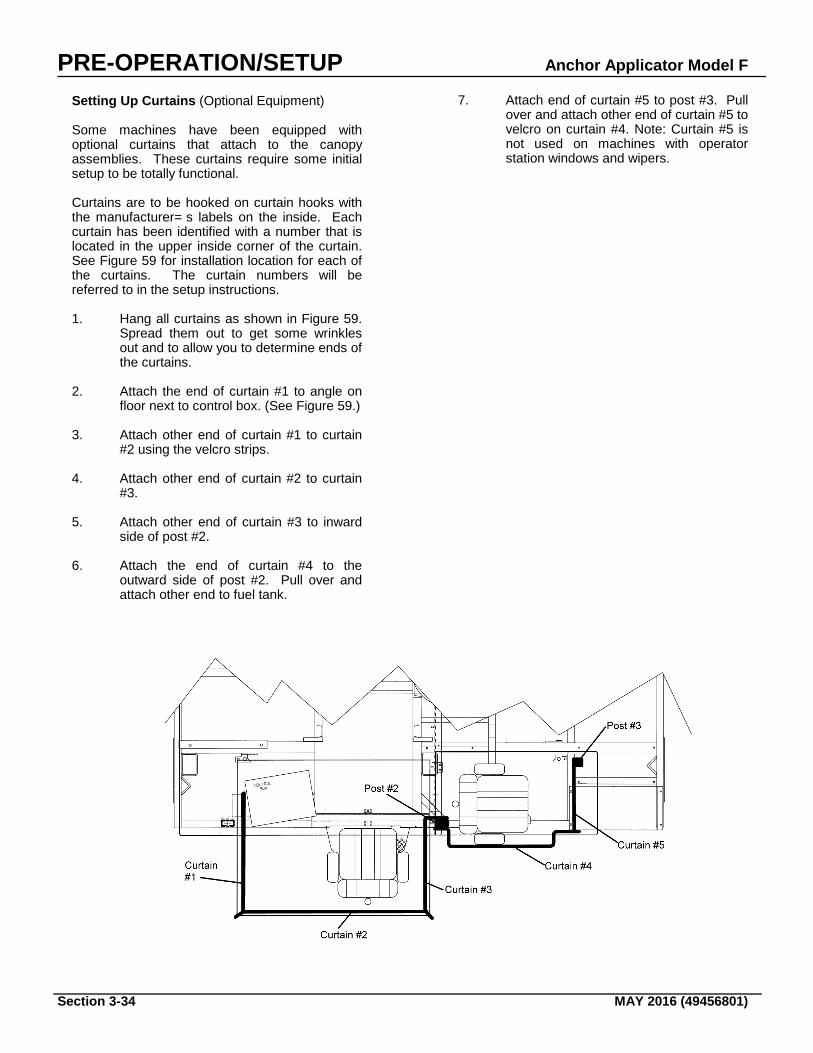
PRE-OPERATION/SETUP Anchor Applicator Model F
Section 3-34 MAY 2016 (49456801)
Setting Up Curtains (Optional Equipment) Some machines have been equipped with optional curtains that attach to the canopy assemblies. These curtains require some initial setup to be totally functional. Curtains are to be hooked on curtain hooks with the manufacturer= s labels on the inside. Each curtain has been identified with a number that is located in the upper inside corner of the curtain. See Figure 59 for installation location for each of the curtains. The curtain numbers will be referred to in the setup instructions. 1. Hang all curtains as shown in Figure 59.
Spread them out to get some wrinkles out and to allow you to determine ends of the curtains.
2. Attach the end of curtain #1 to angle on
floor next to control box. (See Figure 59.) 3. Attach other end of curtain #1 to curtain
#2 using the velcro strips. 4. Attach other end of curtain #2 to curtain
#3. 5. Attach other end of curtain #3 to inward
side of post #2. 6. Attach the end of curtain #4 to the
outward side of post #2. Pull over and attach other end to fuel tank.
7. Attach end of curtain #5 to post #3. Pull over and attach other end of curtain #5 to velcro on curtain #4. Note: Curtain #5 is not used on machines with operator station windows and wipers.
Anchor Applicator Model F OPERATION
MAY 2016 (49456801) Section 3-35
MACHINE OPERATION
To avoid serious injury or death, make certain that the area around and under the machine is clear of all personnel and obstructions BEFORE travelling or working.
Improper use of this machine for any type of operation can cause serious
injury or death.
Do not permite unauthorized personnel to ride in or on the
machine. Falling from a moving vehicle may cause serious injury or
death. Before operating this machine you should be aware of the difference between the two types of Automatic Cycle Shutdowns and the Emergency Shutdown of the machine.
AUTOMATIC CYCLE MANUAL SHUTDOWN
The automatic sequence can be stopped at any time by depressing the Auto Stop button located inside the Automatic portion on the operator= s control panel. This is considered a AManual@ Shutdown of the Automatic Cycle. Refer to Restart After Manual Shutdown for instructions on restarting the machine.
AUTOMATIC CYCLE AUTO SHUTDOWN
If the anchors, sliding jaws, or any other part of the jaw arm assembly should hit the tie, the rail, a large stone or any other object which offers abnormal opposition, prior to the application of the anchor, a pressure switch signals the logic system that an operating fault exists. The
operating sequence is immediately interrupted and the machine automatically returns to the ready position. Refer to Restart After Automatic Shutdown for instructions on restarting the machine.
EMERGENCY SHUTDOWN
The emergency shutdown should be used only when the engine does not respond to the normal stop engine procedure or in the event of an emergency where time is critical.
To shut down the engine, push the EMERGENCY STOP pushbutton located in the upper center of the Logic Box control panel or on either Remote Operator Control Box. Never use the emergency shutdown system except in an emergency. DO NOT USE THIS METHOD AS A SHORTCUT TO TURNING OFF THE ENGINE!!
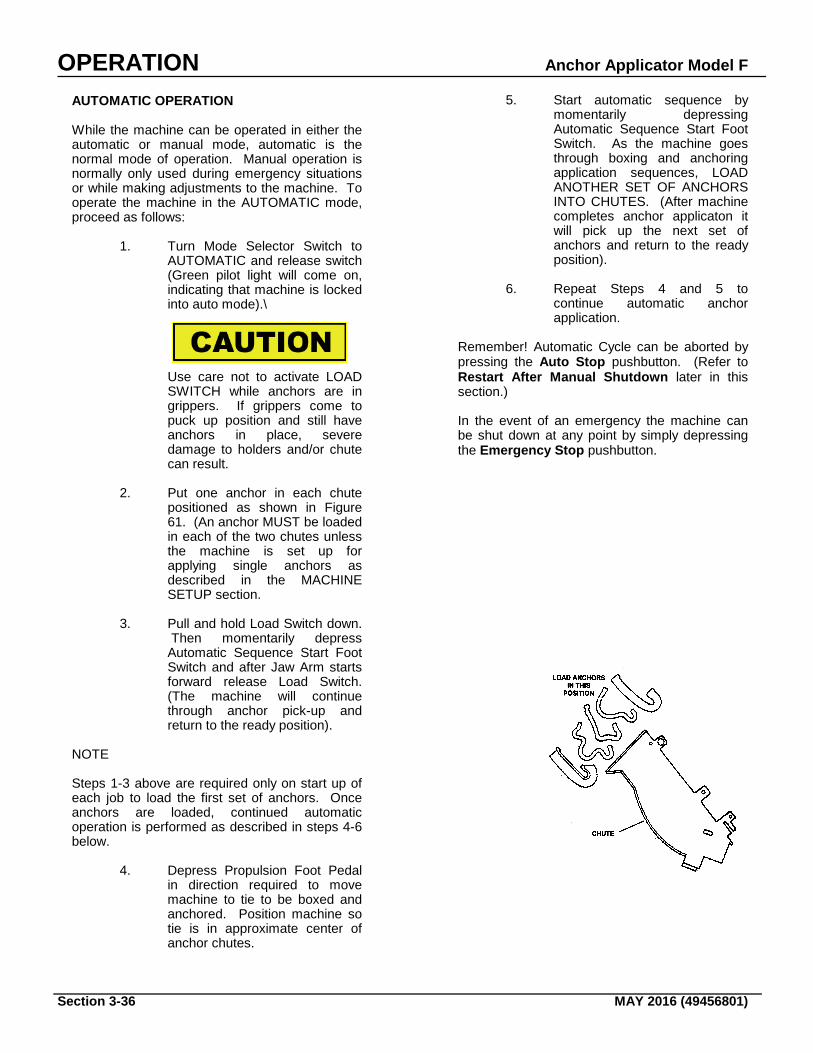
OPERATION Anchor Applicator Model F
Section 3-36 MAY 2016 (49456801)
AUTOMATIC OPERATION While the machine can be operated in either the automatic or manual mode, automatic is the normal mode of operation. Manual operation is normally only used during emergency situations or while making adjustments to the machine. To operate the machine in the AUTOMATIC mode, proceed as follows:
1. Turn Mode Selector Switch to AUTOMATIC and release switch (Green pilot light will come on, indicating that machine is locked into auto mode).\
Use care not to activate LOAD SWITCH while anchors are in grippers. If grippers come to puck up position and still have anchors in place, severe damage to holders and/or chute can result.
2. Put one anchor in each chute
positioned as shown in Figure 61. (An anchor MUST be loaded in each of the two chutes unless the machine is set up for applying single anchors as described in the MACHINE SETUP section.
3. Pull and hold Load Switch down.
Then momentarily depress Automatic Sequence Start Foot Switch and after Jaw Arm starts forward release Load Switch. (The machine will continue through anchor pick-up and return to the ready position).
NOTE Steps 1-3 above are required only on start up of each job to load the first set of anchors. Once anchors are loaded, continued automatic operation is performed as described in steps 4-6 below.
4. Depress Propulsion Foot Pedal in direction required to move machine to tie to be boxed and anchored. Position machine so tie is in approximate center of anchor chutes.
5. Start automatic sequence by momentarily depressing Automatic Sequence Start Foot Switch. As the machine goes through boxing and anchoring application sequences, LOAD ANOTHER SET OF ANCHORS INTO CHUTES. (After machine completes anchor applicaton it will pick up the next set of anchors and return to the ready position).
6. Repeat Steps 4 and 5 to
continue automatic anchor application.
Remember! Automatic Cycle can be aborted by pressing the Auto Stop pushbutton. (Refer to Restart After Manual Shutdown later in this section.) In the event of an emergency the machine can be shut down at any point by simply depressing the Emergency Stop pushbutton.
Anchor Applicator Model F OPERATION
MAY 2016 (49456801) Section 3-37
RESTART AFTER AUTOMATIC SHUTDOWN When an automatic stop has been carried out, return the machine to service as follows: 1. Correct the operating fault. If the
machine was not centered properly over the tie, spot the machine so that there will be no interference with the jaw arm assembly and the tie. If a stone or object in the ballast is causing the operating fault, remove the object.
2. Check to be certain both anchors are in
the holders. If both anchors are in the holders, restart the automatic cycle by depressing the Start Sequence Foot Switch momentarily. If one of both anchors are missing, proceed to step 3.
3. If one anchor is still in a holder, depress
STOP pushbutton (to de-energize the system) and remove anchor using a long handle hook. Only when both anchors are empty restart machine as described under AUTOMATIC OPERATION.
RESTART AFTER MANUAL SHUTDOWN The automatic sequence can be stopped at any time by depressing the Auto Stop button located inside the Automatic portion on the operator= s control panel. When a manual stop has been executed, the machine is returned to service as follows: 1. If the machine was stopped due to a
hazardous condition or obstruction, the hazard must be remedied or the obstruction removed before operation is continued. If one or both of the anchors has dropped out, refer to the instructions under AUTOMATIC OPERATION for the proper procedure on anchor pickup and continued operation.
2. With both anchors in place either
a. Return the control system to the AUTOMATIC mode. As soon as the Mode Selector is switched to automatic the gripper cylinders are activated and the anchors will be held during the machine’s return to the ready position. Restart the automatic cycle by momentarily depressing the foot switch; or
b. Complete the aborted cycle
manually as described under
MANUAL OPERATION below. In the event of an emergency, use the red EMERGENCY STOP pushbutton on the control panel. This will shut down the machine.
OPERATION Anchor Applicator Model F
Section 3-38 MAY 2016 (49456801)
MANUAL OPERATION The machine is normally operated in the automatic mode, however, all of the hydraulic sequences of the machine can be operated by using the manual switches. Manual operation is used mainly to complete an aborted automatic operation or while making adjustments to the machine as described under the MACHINE SETUP. To operate the machine through a complete cycle proceed as follows: NOTE: If the machine is to be operated manually, after an automatic sequence, it will first be necessary to break the (locked in) automatic circuit by depressing the STOP pushbutton OR switching the Mode Selector Switch to MANUAL. The steps below describe a compete manual anchor application procedure from start to finish. To complete an aborted automatic cycle, it may not be necessary to go through all the steps. However, it is recommended you read the entire list of instructions before using the Manual Mode. Then, after putting the machine in the Manual Mode, start at the step following the procedure where the automatic cycle was aborted.
1. Put Mode Selector Switch in MANUAL position (Red pilot light will come on indicating machine is in manual mode).
2. Move Jaw Arm out by holding
Jaw Arm In-Out Switch forward in OUT position and release switch when arm has reached the full out position.
3. Raise the clamp arm by holding
Clamp Arm Up-Down Switch forward in the UP position.
Under no circumstances apply a single anchor unless machine has been properly prepared for this type of operation. Applying a single anchor without making the proper adjustments will damage the unload gripper cylinder rod.
4. Put one anchor in each chute as
shown in Illustration 10.
5. Bring jaw arm into pickup position by holding Jaw Arm In-Out Switch down in the IN
position. Release switch when arm has reached full in position.
6. Pick up anchors by holding Door
Open and Grip Switch up in the on position. This switch must be held in the on position until the anchors are to be applied as described in Step 9 below. Releasing this switch too soon will drop the anchors before they can be applied.
7. Move Jaw Arm back by holding
Jaw Arm In-Out Switch down in the OUT position. Release switch when arm is fully out.
8. Lower Clamp Arm by holding
Clamp Arm Up-Down Switch in the DOWN position. Release switch when arm is fully down.
9. Bring Jaw Arm in to apply
anchors by holding Jaw Arm In-Out Switch down in the IN position - as the anchors just begin to enter under rail hold Box-Unbox Switch up in the BOX position and release the Door Open and Grip Switch.
10. Release Box-Unbox Switch after
anchors have been applied. 11. Return Jaw Arm to OUT position
by holding Jaw Arm In-Out Switch in OUT position until arm is fully out.
12. Return clamp arm to raised
position by holding Clamp Arm Switch up in the UP position. This returns machine to a “Ready” position.
Anchor Applicator Model F OPERATION
MAY 2016 (49456801) Section 3-39
Winch Operation Your machine is equipped with a hydraulic winch for loading materials onto the deck of the machine. In order for the winch to be fully operational, it must have the interlock pin set so that the boom can swing fully from left to right without the lock resetting in another hole. This is accomplished by pulling the interlock handle on the boom mast out until the spring compresses enough to allow the spring pin to move behind the bar located beneath the bracket. Releasing handle allows free movement of boom. To move the winch assembly, pull down on the t-handle until pin releases from hole. Move to new location, release handle. To raise a load: Pull chain handle to left or right* To stop a load: Release chain handle To lower the load: Pull chain handle to the left or right* *Depends on the position of the boom and where you are standing. Under no circumstances is the winch to be used for towing or for lifting loads in excess of 300 pounds. After winch work is complete, secure cable to boom. Refer to LOCKUP section for instructions on locking up the boom and winch assembly. Emergency Procedures 1. If a hydraulic hose fails, shut down the
machine immediately, determine cause of failure, correct condition.
2. If indications on gauges are not within
the normal range, shut down the engine. Repair before further operation.
3. Emergency cylinder actuation requires
the optional Hand Pump. See below. EMERGENCY PUMP OPERATION Refer to the Preface of the Hydraulic Section.
OPERATION Anchor Applicator Model F
Section 3-40 MAY 2016 (49456801)
AFTER OPERATION General 1. Install lock-ups. See LOCK-UPS section. 2. Press the Electrical Interlock Button on
the Main Control Panel. 3. Set engine speed to low position and turn
pump off. Let engine idle for 5 minutes. 4. Shut off engine by returning ignition
switch to the full counterclockwise position.
5. Return all switches to their "Pre-
Operational" state using the Pre-Operational Checklist as a guide.
6. Lower logic box cover and secure with
padlocks.
Never shut off battery disconnect switch with engine running. This could cause damage to the voltage regulator, alternator, and/or electrical system. 7. Turn off battery disconnect switch. Lock
battery box. Parking or Locating Machine 1. Park or locate machine on level track
area, if possible; and where it will not be exposed to excessive dust.
2. If the machine was towed, disconnect
towing vehicle and set the brakes. Move the towing vehicle well clear of the parked machine.
Rotating Machine
The machine has a turntable which allows the machine to be lifted off of the tracks and rotated. The only function of this turntable is to rotate the machine. The turntable base is stored on the rear deck of the machine.
When machine is to be turned using the turntable, raise machine only high enough for the wheels to clear the rail. Any machine can be hazardous when
raised. Take all necessary precautions before raising the machine. Do NOT, under any
circumstances, climb under this machine when using the turntable
To lift and rotate the machine, proceed with the following steps: 1. Center turntable base across two solid
and level ties. 2. Unlock set-off valve handle. Slowly lift
handle to lower turntable until it comes into contact with ties.
3. Hold valve hand lever until the machine
is fully raised off the track. Center the hand lever to lock in place.
4. Use manpower to rotate the machine.
The wheels should be directly above the track after rotating the machine.
5. Slowly move the Set-Off Valve hand
lever downward. The Turntable Cylinder will retract and the machine will lower onto the track.
6. Lock up set-off valve.
Anchor Applicator Model F OPERATION
MAY 2016 (49456801) Section 3-41
Towing Maximum towing speed is 20 mph. Reduce speed accordingly as dictated by weather or track conditions.
Do not ride on tow bar between the machine and the towing vehicle. Falling
from a moving vehicle may cause serious injury or death.
Remember that the machine weight may approach the weight of the towing vehicle. Maintain increased stopping distance accordingly. The following steps must be taken before towing your machine: 1. Install Lock-Ups. See LOCK-UPS
section. 2. Make certain turntable has been raised. 3. Remove drive chain(s) if machine is to
be towed a long distance. 4. Inspect the towing vehicle coupler for
damage or loose parts. 5. Back towing vehicle to the machine and
engage the couplers. Keep hands and fingers clear of the coupling device and all other pinch points.
6. Ensure that the coupling device is fully
engaged, closed, and locked.
To avoid serious personal injury, stay clear of brake springs when using hydraulic compression to place brake lock pins. 7. Install Brake Lock Pins, using
instructions on next page. 8. Ensure that the coupling device and rear
frame members on the towing vehicles will not interfere with or restrict motion of any part of the machine when maneuvering.
9. When towing is complete, engage brake
by removing the Brake Lock Pins.
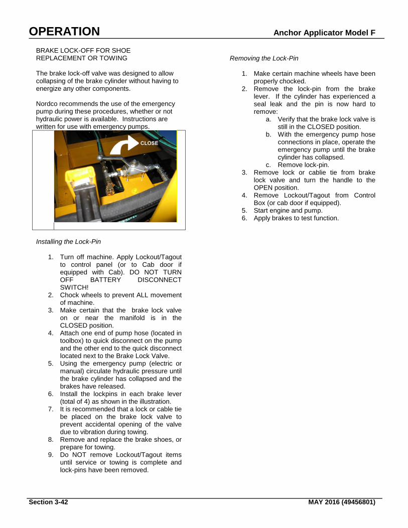
OPERATION Anchor Applicator Model F
Section 3-42 MAY 2016 (49456801)
BRAKE LOCK-OFF FOR SHOE REPLACEMENT OR TOWING The brake lock-off valve was designed to allow collapsing of the brake cylinder without having to energize any other components. Nordco recommends the use of the emergency pump during these procedures, whether or not hydraulic power is available. Instructions are written for use with emergency pumps.
Installing the Lock-Pin
1. Turn off machine. Apply Lockout/Tagout to control panel (or to Cab door if equipped with Cab). DO NOT TURN OFF BATTERY DISCONNECT SWITCH!
2. Chock wheels to prevent ALL movement of machine.
3. Make certain that the brake lock valve on or near the manifold is in the CLOSED position.
4. Attach one end of pump hose (located in toolbox) to quick disconnect on the pump and the other end to the quick disconnect located next to the Brake Lock Valve.
5. Using the emergency pump (electric or manual) circulate hydraulic pressure until the brake cylinder has collapsed and the brakes have released.
6. Install the lockpins in each brake lever (total of 4) as shown in the illustration.
7. It is recommended that a lock or cable tie be placed on the brake lock valve to prevent accidental opening of the valve due to vibration during towing.
8. Remove and replace the brake shoes, or prepare for towing.
9. Do NOT remove Lockout/Tagout items until service or towing is complete and lock-pins have been removed.
Removing the Lock-Pin
1. Make certain machine wheels have been properly chocked.
2. Remove the lock-pin from the brake lever. If the cylinder has experienced a seal leak and the pin is now hard to remove:
a. Verify that the brake lock valve is still in the CLOSED position.
b. With the emergency pump hose connections in place, operate the emergency pump until the brake cylinder has collapsed.
c. Remove lock-pin. 3. Remove lock or cablie tie from brake
lock valve and turn the handle to the OPEN position.
4. Remove Lockout/Tagout from Control Box (or cab door if equipped).
5. Start engine and pump. 6. Apply brakes to test function.
Anchor Applicator Model F MAINTENANCE
MAY 2016 (49456801) Section 4-1
-GENERAL Sound service and maintenance practices will ensure that the machine continues to meet your demanding requirements. At each scheduled maintenance interval, perform all previous maintenance operations in addition to the ones specified. NOTE: Recommended service intervals are for
normal operating conditions. Service more often if engine is operated under adverse conditions. Neglecting maintenance can result in failures or permanent damage to equipment.
SAFETY DURING MAINTENANCE Alert others in the area that service or maintenance is being performed on this machine. Become familiar with, and use, lockout/tagout procedures when performing maintenance on this machine. See LOCKOUT/TAGOUT REQUIREMENTS in the Safety Section of this manual. Do not start the engine if repairs or work is being performed alone. You should always have at least two people working together if the engine must be run during service. One person needs to remain in the command position (at the controls), ready to stop the machine and shut off engine if the need arises.
NORDCO'S SERVICE NETWORK Need assistance? It's only a phone call away! As the owner of a NORDCO product, you have a complete network of service technicians that are prepared to meet your parts and service needs. If you experience problems, contact NORDCO's Service Manager. REQUESTING ASSISTANCE If you have any questions regarding maintenance and service on this machine, please call your local Nordco Representative or: Nordco Service Manager 1-800-445-9258 (USA and Canada) The process will be faster if you have the following information in hand before calling: 1. The Machine Name 2. The Type or Model of Machine 3. The Serial Number SERVICE POINTS Service points on this machine (adjustments, inspections, lubrication, etc.) are listed on the follow
Always perform LOTO procedures when performing maintenance, making adjustments, or whenever unintended movement of machine could occur; unless directed otherwise. Failure to comply will result in severe personal injury and/or damage to the machine.
To avoid serious injury or death, make certain that the area around and under the machine is clear of all personnel and obstructions BEFORE traveling or working
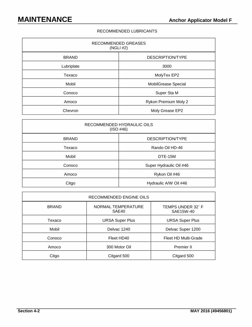
MAINTENANCE Anchor Applicator Model F
Section 4-2 MAY 2016 (49456801)
RECOMMENDED LUBRICANTS
RECOMMENDED GREASES (NGLI #2) BRAND
DESCRIPTION/TYPE
Lubriplate
3000
Texaco
MolyTex EP2
Mobil
MobilGrease Special
Conoco
Super Sta M
Amoco
Rykon Premium Moly 2
Chevron
Moly Grease EP2
RECOMMENDED HYDRAULIC OILS (ISO #46) BRAND
DESCRIPTION/TYPE
Texaco
Rando Oil HD-46
Mobil
DTE-15M
Conoco
Super Hydraulic Oil #46
Amoco
Rykon Oil #46
Citgo
Hydraulic A/W Oil #46
RECOMMENDED ENGINE OILS BRAND
NORMAL TEMPERATURE SAE40
TEMPS UNDER 32˚ F
SAE15W-40 Texaco
URSA Super Plus
URSA Super Plus
Mobil
Delvac 1240
Delvac Super 1200
Conoco
Fleet HD40
Fleet HD Multi-Grade
Amoco
300 Motor Oil
Premier II
Citgo
Citgard 500
Citgard 500
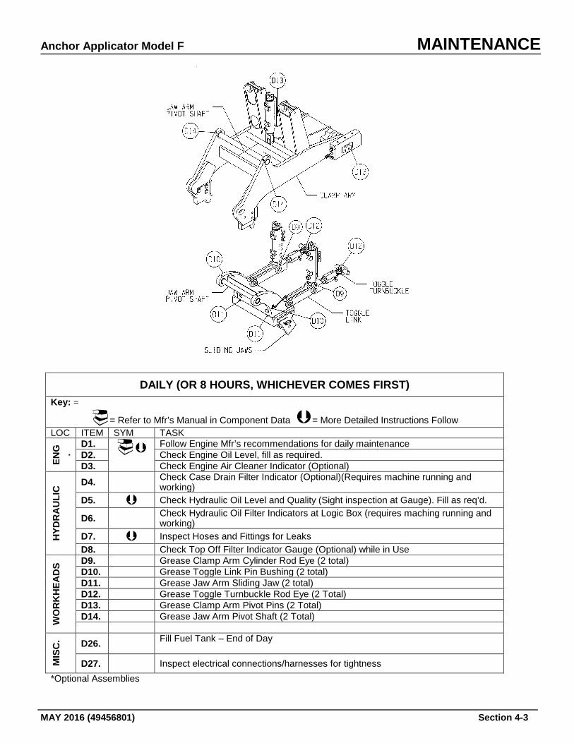
Anchor Applicator Model F MAINTENANCE
MAY 2016 (49456801) Section 4-3
DAILY (OR 8 HOURS, WHICHEVER COMES FIRST) Key: =
= Refer to Mfr’s Manual in Component Data = More Detailed Instructions Follow LOC ITEM SYM TASK
ENG .
D1. Follow Engine Mfr’s recommendations for daily maintenance D2. Check Engine Oil Level, fill as required. D3. Check Engine Air Cleaner Indicator (Optional)
HYD
RA
ULI
C D4. Check Case Drain Filter Indicator (Optional)(Requires machine running and
working) D5. Check Hydraulic Oil Level and Quality (Sight inspection at Gauge). Fill as req’d.
D6. Check Hydraulic Oil Filter Indicators at Logic Box (requires maching running and working)
D7. Inspect Hoses and Fittings for Leaks D8. Check Top Off Filter Indicator Gauge (Optional) while in Use
WO
RK
HEA
DS
D9. Grease Clamp Arm Cylinder Rod Eye (2 total) D10. Grease Toggle Link Pin Bushing (2 total) D11. Grease Jaw Arm Sliding Jaw (2 total) D12. Grease Toggle Turnbuckle Rod Eye (2 Total) D13. Grease Clamp Arm Pivot Pins (2 Total) D14. Grease Jaw Arm Pivot Shaft (2 Total)
MIS
C. D26. Fill Fuel Tank – End of Day
D27. Inspect electrical connections/harnesses for tightness
*Optional Assemblies
MAINTENANCE Anchor Applicator Model F
Section 4-4 MAY 2016 (49456801)
Detailed Daily Instructions
D2. Check Engine Oil Level
Check the oil level daily with the engine stopped. If necessary, add sufficient oil to raise the level to the proper mark on the dipstick. All diesel engines are designed to use some oil, so periodic addition of oil is normal. If the oil level is constantly above normal and excess lube oil has not been added to the crankcase, contact the engine maker's authorized service outlet listed in the Engine Manual. Fuel or coolant dilution of lube oil can result in serious engine damage. Never operate the engine with the oil level below the "L" (low) mark or above the "H" (high) mark on the oil dipstick. Wait at least 15 minutes after shutting off the engine to check the oil. This allows time for the oil to drain to the oil pan. Check Engine Manufacturer’s Manual for Engine Oil Capacity.
D5. Check Hydraulic Oil Level and Quality – Sight Inspection Only
Inspect the oil level on a daily basis (or every 10 hours of operation) by reading the sight gauge located on the side of the reservoir. At full level, the oil should be to the top of the sight gauge. The hydraulic system uses SAE-20 (ISO 46) oil. Before filling the system with hydraulic oil, be sure that the fluid is as specified and that it is clean. Do not use cloth strainers or fluid that has been stored in contaminated containers. Care should be taken to keep the hydraulic oil free of dust, water, sealing compounds and other foreign matter. While using the sight gauge, verify oil quality. If oil becomes dark or milky colored, it should be changed immediately. NOTE: Always add hydraulic oil to reservoir through a filter. NEVER OVERFILL RESERVOIR. Never use hydraulic brake fluid in lieu of hydraulic oil.
Anchor Applicator Model F MAINTENANCE
MAY 2016 (49456801) Section 4-5
D7. Inspect Hoses and Fittings for Leaks 1. Look for loose or disconnected hoses. An oil spot below the machine is a good indication of a loose hose or hydraulic component. 2. Make certain shut-off valve on suction strainer is OPEN. Opening valve can often correct what appears to be a malfunction. 3. Inspect all vital hose connections, especially at main pump and the main pump hose connection at the manifold. 4. Look for cover damage and/or indications of twisted, worn, crimped, brittle, cracked, or leaking hoses. Hoses with their outer cover worn through or otherwise damages should be considered unfit for further service.
D27. Inspect Electrical Connections/Harnesses for Tightness Daily inspection of the harnesses connected to the controllers, operator control box, footswitches, and logic box are required. Harnesses that may not have proper connection could cause problems in starting and stopping the machine. In addition to harness connections, the footswitch should be inspected on a regular basis to guard against wear, deterioration, etc. If you notice excessive wear or breakdown, replace the switch.
MAINTENANCE Anchor Applicator Model F
Section 4-6 MAY 2016 (49456801)
WEEKLY (OR 40 HOURS, WHICHEVER COMES FIRST) Key: =
= Refer to Mfr’s Manual in Component Data = More Detailed Instructions Follow LOC ITEM SYM TASK
MIS
C.
W1. Perform all Daily Lubrication and Maintenance Procedures W2. Check Battery Condition. W3. Oil Propulsion Chains W4. Oil Propulsion Chain Adjusting Nuts W5. Grease Axle Bearings W6. Check Suction Strainer Elementa
WO
RK
HEA
DS
W10. Oil Toggle Turnbuckle Threads (2 Turnbuckles) W11. Oil Chute Up/Down Turnbuckle Threads (2 Turnbuckles) W12. Oil Chute Door Hinge Pin (4 Total) W13. Oil Chute Door Width Turnbuckle Threads W14. Oil Chute Mounting Lateral Adjustment Screws W15. Oil Chute In/Out Adjusting Screw
a. Check Suction Strainer Element first 40 hours of operation and yearly after initial inspection.
Anchor Applicator Model F MAINTENANCE
MAY 2016 (49456801) Section 4-7
Detailed Weekly Instructions
W3. Oil Propulsion Chains When inspecting the drive chain, the chain should be nearly taut, with 1/4" (.635 Cm) play when depressed at the center. If not, adjustment is necessary see below. If the chain is too tight, the eccentricity of the sprockets may cause the chain to stretch and/or break. If the chain is too loose, the starting and stopping of the machine will shock load the chain, resulting in short chain life or failure. A worn or stretched chain will also cause short sprocket life as the load will not be carried by all of the teeth on the sprocket - resulting in excessive load on a few teeth. To adjust the drive chain: 1. Remove propulsion chain guard. 2. Unscrew the adjusting screw locknut, but do not remove it from the screw. 3. Turn adjusting screw clockwise (CW) to tighten the chain or counter-clockwise (CCW) to loosen the chain. 4. Once the desired tightness has been reached, tighten the adjusting screw locknut. 5. Reinstall the chain guard.
W6. Grease Axle Bearings
Periodic inspection of the axle bearings for wear and breakdown are required to keep this machine functioning properly. Inspect hardware for proper fit and secure all loose nuts and bolts. The wheel bearing grease fittings are located on the underside of the pillow blocks. Remote wheel bearing grease fittings for the wheels are located on the outside of the frame close to each axle. Weather conditions affect the time intervals of greasing. In general, a small amount of grease should be ok. Overgreasing may cause seal failure. Grease hardens with age. When this occurs, the bearing should be taken apart, cleaned, and relubricated following the manufacturer’s instructions on the component data sheet. If supplied, check automatic greasing assemblies for proper charge.
MAINTENANCE Anchor Applicator Model F
Section 4-8 MAY 2016 (49456801)
W7. Check Suction Strainer Element Located on the side of the reservoir, remove and inspect the filter after the first 40 hours of operation and every year thereafter. Clean as required. To access filter: 1. Turn off engine, Make certain suction valve is closed (off)(ccw). 2. Remove padlock (1) and pull out plug attached to cable. 3. Using Allen wrench, turn screw (2) inside of plug housing clockwise to open (counterclockwise to close). 4. Remove six capscrews and lift off front cover. Reverse process to reattach cover. NOTE:If for any reason removal of suction line filter is necessary, you must seal the hydraulic tank to prevent external contamination.
Anchor Applicator Model F MAINTENANCE
MAY 2016 (49456801) Section 4-9
MONTHLY (OR 150 HOURS, WHICHEVER COMES FIRST) Key: =
= Refer to Mfr’s Manual in Component Data = More Detailed Instructions Follow LOC ITEM SYM TASK
MIS
CEL
LAN
EOU
S M1. Perform all Daily and Weekly Lubrication and Maintenance Procedures M2. Check Fan, Alternator and Generator Belts M3. Change Engine Oil and Filters M4. Check Brake Shoes for Wear M5. Run Pressure Checks on Main Pump and Propulsion M6. Check Oil Cooler, clean as necessary M7. Grease Winch Boom
Detailed Monthly Instructions
M2. Check Fan, Alternator and Generator Belts
Check the belts and tighten the fan drive, battery-charging alternator and other accessory drive belts. Belts should be neither too tight nor too loose. Belts that are too tight impose excess loads on the crankshaft, fan, and/or alternator bearings, shortening both belt and bearing life. Excessively overtightened belts can result in crankshaft breakage. A loose belt will slip and may cause damage to accessory components. Replace all belts in a set when one is worn. Single belts of similar size should not be used as a substitute for a matched belt set. Premature belt wear can result because of belt length variation.
MAINTENANCE Anchor Applicator Model F
Section 4-10 MAY 2016 (49456801)
M4. Check Brake Shoes for Wear Replace brake shoes when the pad is less than 1/4 (.64 cm) thick. To replace brake shoes: 1. Override the brake valve cylinder on the
main manifold until the cylinder collapses. 2. Once the cylinder has been collapsed,
close the brake shut-off valve located behind the left main manifold. This will trap oil in the cylinder and keep the cylinder collapsed.
3. Insert the Brake lockup pins. 4. Turn off machine, following
Lockup/Tagout procedures. 5. Remove the lower cotter pin and pin
holding brake shoe bracket to brake lever. (See Item #1 in Figure).
6. Lift up the brake bracket to gain access to
the brake shoe. 7. Remove brake shoe mounting hardware
and replace brake shoe. Make certain you have reinstalled the mounting hardware!
8. Lower the brake bracket and reinstall the
pin and cotter pin. Repeat Steps 5 through 8 for all brake shoes that need replacing. After that is done, continue on with the following steps: 9. Remove the brake lockup pins. 10. Return machine to service following the
Lockout/Tagout procedures. Turn on machine.
11. Open shut-off valve.
M5. Run Pressure Checks on Main Pump and Propulsion
Pressure checks should be performed every 250 hours or monthly after the engine and hydraulics have thoroughly warmed up (oil temperature has reached 100°F [37.8°C] minimum). Before performing these checks, read and understand all OPERATION instructions, warnings and cautions.
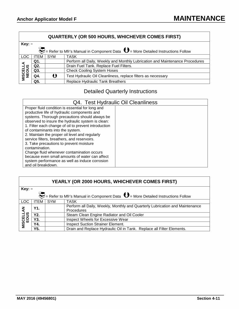
Anchor Applicator Model F MAINTENANCE
MAY 2016 (49456801) Section 4-11
QUARTERLY (OR 500 HOURS, WHICHEVER COMES FIRST) Key: =
= Refer to Mfr’s Manual in Component Data = More Detailed Instructions Follow LOC ITEM SYM TASK
MIS
CEL
LAN
EOU
S
Q1. Perform all Daily, Weekly and Monthly Lubrication and Maintenance Procedures Q2. Drain Fuel Tank. Replace Fuel Filters. Q3. Check Cooling System Hoses Q4. Test Hydraulic Oil Cleanliness, replace filters as necessary Q5. Replace Hydraulic Tank Breathers
Detailed Quarterly Instructions
Q4. Test Hydraulic Oil Cleanliness
Proper fluid condition is essential for long and productive life of hydraulic components and systems. Thorough precautions should always be observed to insure the hydraulic system is clean: 1. Filter each change of oil to prevent introduction of contaminants into the system. 2. Maintain the proper oil level and regularly service filters, breathers, and reservoirs. 3. Take precautions to prevent moisture contamination. Change fluid whenever contamination occurs because even small amounts of water can affect system performance as well as induce corrosion and oil breakdown.
YEARLY (OR 2000 HOURS, WHICHEVER COMES FIRST) Key: =
= Refer to Mfr’s Manual in Component Data = More Detailed Instructions Follow LOC ITEM SYM TASK
MIS
CEL
LAN
EOU
S
Y1. Perform all Daily, Weekly, Monthly and Quarterly Lubrication and Maintenance Procedures
Y2. Steam Clean Engine Radiator and Oil Cooler Y3. Inspect Wheels for Excessive Wear Y4. Inspect Suction Strainer Element. Y5. Drain and Replace Hydraulic Oil in Tank. Replace all Filter Elements.
MAINTENANCE Anchor Applicator Model F
Section 4-12 MAY 2016 (49456801)
MAINTENANCE FOR EXTREME CONDITIONS Cold Weather
General Problems
Extreme cold generally causes fluids to thicken or gel, presents a risk of freezing and weakening the battery, can crack electrical insulation, can cause difficult starting, and causes rubber and plastic parts to become hard, brittle and easily damaged.
Lubricants
Use the correct grade of lubricants wherever they are used on the machine. Drain and refill if the lubricant is not correct for cold weather operation. See Lubrication under SERVICE AND MAINTENANCE. Cold weather also can cause moisture to accumulate in lubricants. If water is found in any lubricant, drain and refill.
Fuel System
Precautions can be taken to keep moisture out of the fuel system.
1. Keep fuel tank as full as possible to
avoid condensation.
2. Remove ice and snow from the area of the filler opening before refilling. Whenever moisture does accumulate in the fuel system, drain water from tank and filters.
If fuel is seriously contaminated with moisture, drain, flush, and refill fuel tank.
Battery
Keep battery fully charged. Cranking power of battery is reduced in extreme cold.
Engine Operation
Run engine at LOW SPEED only long enough to circulate the oil through the engine, then increase speed to warm up the engine. Extended idling during extremely cold temperatures can cause incomplete combustion and heavy deposit formations on the valves.
Machine Storage
1. Park machine in a sheltered place if
possible.
2. Wet mud or snow should be cleaned from wheels, axles and hubs before it freezes.
3. When the machine is shut down in
extremely cold weather, remove the battery and store it in a moderately warm place. Reinstall battery just prior to starting.
Hot Weather
General
Precautions must be taken to avoid overheating. Check temperature gauge frequently for indications of overheating. When overheated, allow engine to idle until temperature is reduced.
Cooling System
Deutz engines: Check condition of cooling fins frequently. Keep fins and air duct clean and free of dirt that would reduce efficiency. Replace cracked, frayed, or excessively worn belts.
Lubrication
Lubricate the machine with correct grade of lubricants according to lubrication instructions. Change filter elements at shorter intervals than specified in the Maintenance procedures.
Air Cleaners
Check restriction indicator frequently. Service air cleaner at intervals specified in the engine manual.
Rainy or Humid Conditions
Fuel Tank
Keep fuel tank as full as possible and service filters more often than normal.
Lubrication
Keep all moving parts well lubricated.
Paint
If paint is chipped or scratched, the affected area should be refinished immediately to
Anchor Applicator Model F MAINTENANCE
MAY 2016 (49456801) Section 4-13
prevent rapid formation of rust. Remove all loose paint with paint remover, sandpaper, or sandblasting equipment. Apply two coats of primer and, when dry, apply finishing coat of paint.
Dusty or Sandy Areas
General
Sand and dust are abrasives which can cause wear on many parts of the machine. Airborne sand and dust can clog the air cleaners, cooler and radiator. Try to store machine in sheltered area when not in use.
Air Cleaners
Check the air cleaner indicator frequently and reduce the service intervals for the air cleaner. Clean the air cleaner as often as necessary to prevent it from becoming clogged. Lubrication
Lubricate the machine more often then specified in the Lubrication Chart. Clean all fittings and openings thoroughly before lubrication to keep out sand and dust. Take similar precautions with lubricant containers.
Salt Water Areas In salt water areas, keep the machine as clean as possible. Salt water vapor in the air causes corrosion of exposed parts. After operation, wash with fresh water if available. Keep all lubrication points wiped clean and well lubricated.

MAINTENANCE Anchor Applicator Model F
Section 4-14 MAY 2016 (49456801)
This page intentially left blank
Anchor Applicator Model F TROUBLESHOOTING
MAY 2016 (49456801) Section 5-1
TROUBLESHOOTING - GENERAL Troubleshooting is a matter of quickly and logically isolating the cause of a problem and taking corrective action. Operating experience, a thorough understanding of the information in this manual, and accurate maintenance and operation records are the best troubleshooting tools an operator can have. This machine is a group of rather simple systems. If you understand the basic workings of these systems individually and how they relate to each other, troubleshooting becomes a relatively simple task. This general portion of the troubleshooting guide has been broken down into four sections, engine, hydraulics, electrical, and mechanical; and is intended to give you basic troubleshooting guidelines. Local conditions and operating methods may result in problems, causes and remedies not covered in this guide. To use the guide most efficiently, locate a problem that matches the one being experience and, in a step-by-step method, check the causes listed until the correct remedy is found and the problem solved.
Always turn off machine and perform LOTO procedures when performing maintenance, making adjustments, or whenever unintended movement of machine could occur; unless directed otherwise. Failure to comply will result in severe personal injury and/or damage to the machine.
TROUBLESHOOTING Anchor Applicator Model F
Section 5-2 MAY 2016 (49456801)
ENGINE TROUBLESHOOTING When the temperature of diesel fuel is elevated, as occurs when the fuel is circulated through an operating engine, it may pose the following hazards which should be guarded against. Refer to the engine manual for details. The following precautions should be taken to minimize the possibilities of injuries from heated diesel fuel: 1. Whenever possible, it is recommended
that the engine and fuel be given an opportunity to cool down to ambient temperature before performing service operations which could result in the spillage of fuel from the engine or machine fuel system. When this is not possible, protective clothing (face shield, insulated gloves, apron) should be worn when performing these operations.
2. Keep open flames, sparks or other
potential ignition sources away and do not smoke during vehicle refueling and service operations which could result in the escape of liquid or vaporized diesel fuel.
3. Engine or machine fuel systems service
operations should be performed in a well
ventilated area that is kept free of bystanders.
For engine problems not listed in the troubleshooting charts, please refer to the Engine Manual.
Exhaust emissions caused by the use of this machine may cause cancer, birth defects, or other reproductive harm if inhaled.
Disconnect the battery before servicing this machine. Failure to do so could result in personal injury from accidental engine startup. Before starting a new or overhauled engine that has been in storage, consult the engine manufacturers manual for intial startup instructions. Failure to follow those instructions can result in serious engine damage.
Anchor Applicator Model F TROUBLESHOOTING
MAY 2016 (49456801) Section 5-3
ELECTRICAL TROUBLESHOOTING INSPECTION Inspect the electrical system for clues to the malfunction. Check to see if the unit can be operated without further damage to the system. Always check these items before turning on switches or running the machine: 1. Look for bare wires that could cause
grounds or shorts. Shorted wires can damage the charging system.
2. Look for loose or broken wires. 3. Inspect all connections, especially
battery connection points. Cleaning harness connectors or ground connections can often correct what appears to be a malfunction.
4. Check the battery electrolyte level.
Continued loss of electrolyte fluid indicates overcharing or cracked battery case.
5. Inspect for overheated parts after the unit
has been stopped for a while. They will often smell like burned insulation. Put your hand on the alternator. Heat in these parts, when the machine has not been operated for some time, is a sure clue to charging circuit problems.
Many electrical failures cannot be detected even if the machine is started. If your visual inspection does not indicate the possible malfunction refer to the electrical system troubleshooting guide that follows.
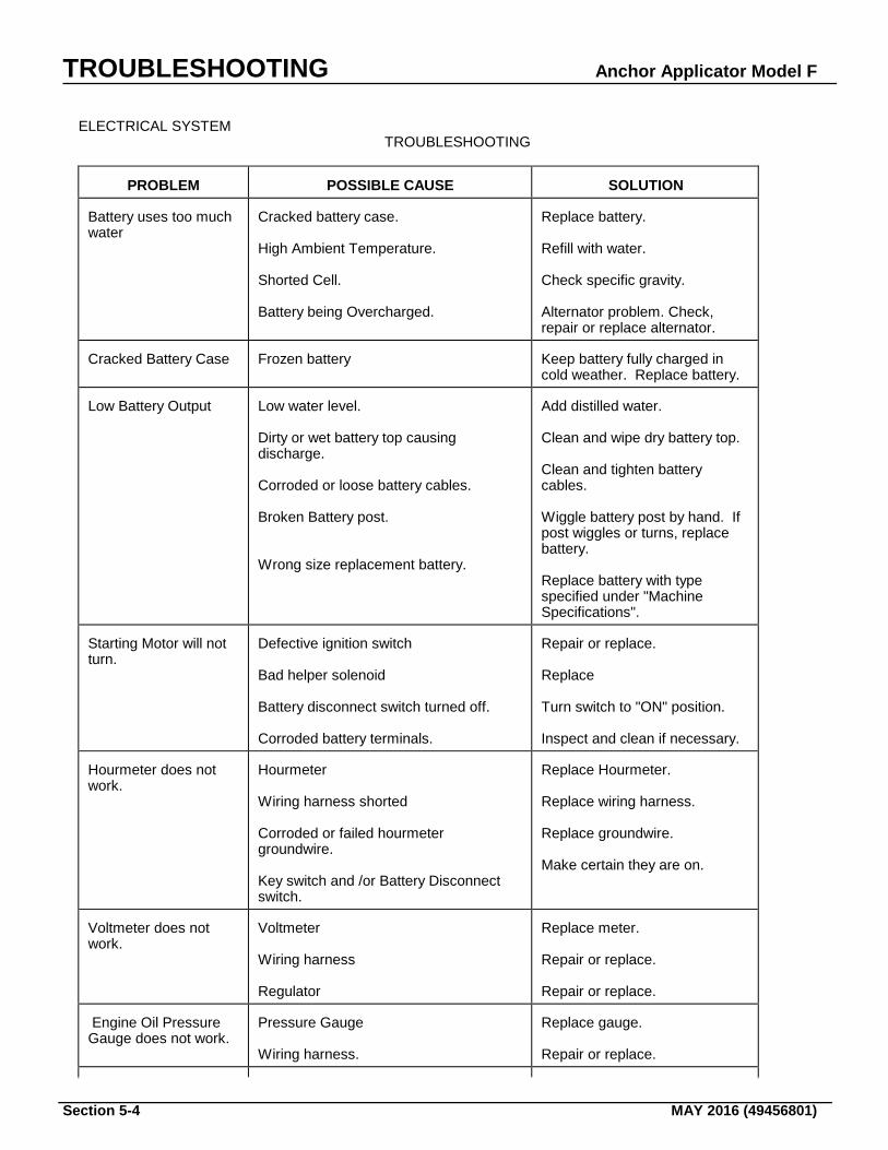
TROUBLESHOOTING Anchor Applicator Model F
Section 5-4 MAY 2016 (49456801)
ELECTRICAL SYSTEM TROUBLESHOOTING
PROBLEM
POSSIBLE CAUSE
SOLUTION
Battery uses too much water
Cracked battery case. High Ambient Temperature. Shorted Cell. Battery being Overcharged.
Replace battery. Refill with water. Check specific gravity. Alternator problem. Check, repair or replace alternator.
Cracked Battery Case
Frozen battery
Keep battery fully charged in cold weather. Replace battery.
Low Battery Output
Low water level. Dirty or wet battery top causing discharge. Corroded or loose battery cables. Broken Battery post. Wrong size replacement battery.
Add distilled water. Clean and wipe dry battery top. Clean and tighten battery cables. Wiggle battery post by hand. If post wiggles or turns, replace battery. Replace battery with type specified under "Machine Specifications".
Starting Motor will not turn.
Defective ignition switch Bad helper solenoid Battery disconnect switch turned off. Corroded battery terminals.
Repair or replace. Replace Turn switch to "ON" position. Inspect and clean if necessary.
Hourmeter does not work.
Hourmeter Wiring harness shorted Corroded or failed hourmeter groundwire. Key switch and /or Battery Disconnect switch.
Replace Hourmeter. Replace wiring harness. Replace groundwire. Make certain they are on.
Voltmeter does not work.
Voltmeter Wiring harness Regulator
Replace meter. Repair or replace. Repair or replace.
Engine Oil Pressure Gauge does not work.
Pressure Gauge Wiring harness.
Replace gauge. Repair or replace.
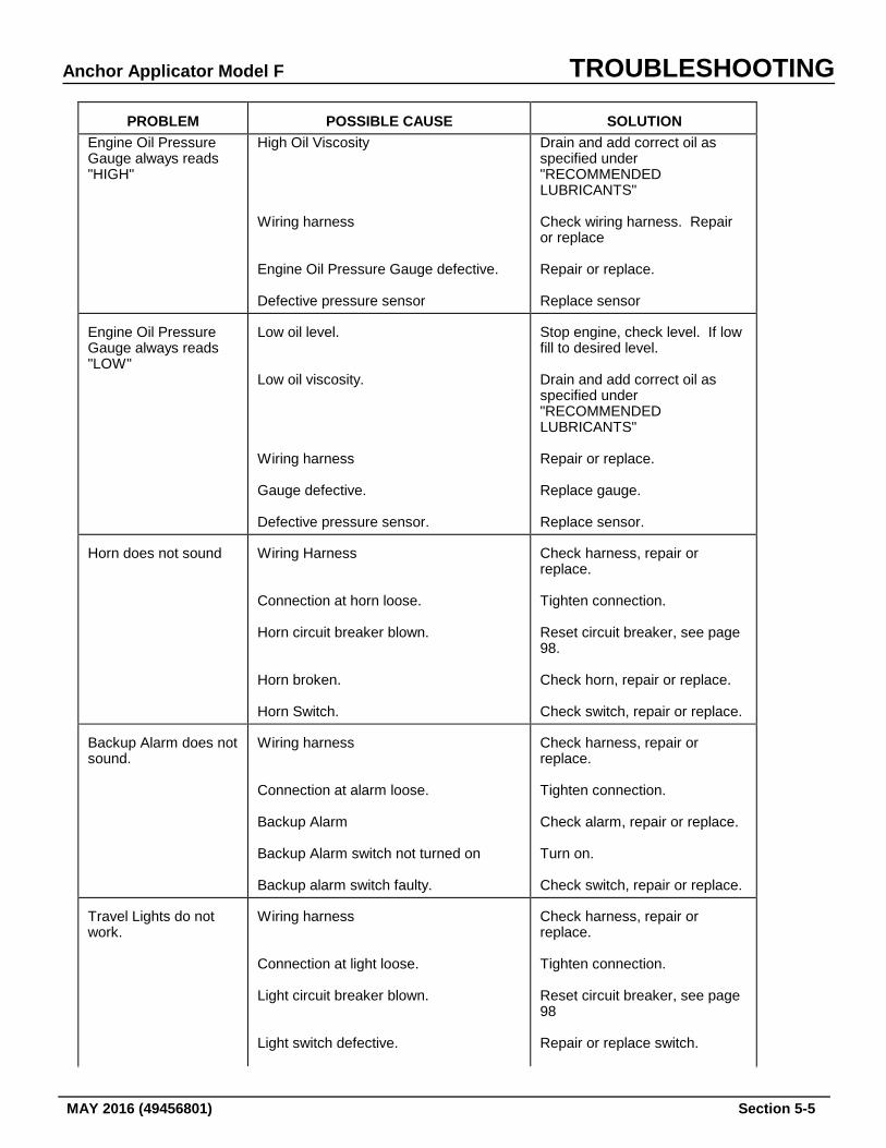
Anchor Applicator Model F TROUBLESHOOTING
MAY 2016 (49456801) Section 5-5
PROBLEM
POSSIBLE CAUSE
SOLUTION
Engine Oil Pressure Gauge always reads "HIGH"
High Oil Viscosity Wiring harness Engine Oil Pressure Gauge defective. Defective pressure sensor
Drain and add correct oil as specified under "RECOMMENDED LUBRICANTS" Check wiring harness. Repair or replace Repair or replace. Replace sensor
Engine Oil Pressure Gauge always reads "LOW"
Low oil level. Low oil viscosity. Wiring harness Gauge defective. Defective pressure sensor.
Stop engine, check level. If low fill to desired level. Drain and add correct oil as specified under "RECOMMENDED LUBRICANTS" Repair or replace. Replace gauge. Replace sensor.
Horn does not sound
Wiring Harness Connection at horn loose. Horn circuit breaker blown. Horn broken. Horn Switch.
Check harness, repair or replace. Tighten connection. Reset circuit breaker, see page 98. Check horn, repair or replace. Check switch, repair or replace.
Backup Alarm does not sound.
Wiring harness Connection at alarm loose. Backup Alarm Backup Alarm switch not turned on Backup alarm switch faulty.
Check harness, repair or replace. Tighten connection. Check alarm, repair or replace. Turn on. Check switch, repair or replace.
Travel Lights do not work.
Wiring harness Connection at light loose. Light circuit breaker blown. Light switch defective.
Check harness, repair or replace. Tighten connection. Reset circuit breaker, see page 98 Repair or replace switch.
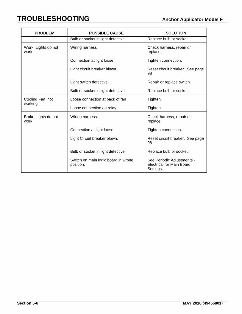
TROUBLESHOOTING Anchor Applicator Model F
Section 5-6 MAY 2016 (49456801)
PROBLEM
POSSIBLE CAUSE
SOLUTION
Bulb or socket in light defective. Replace bulb or socket. Work Lights do not work.
Wiring harness Connection at light loose. Light circuit breaker blown. Light switch defective. Bulb or socket in light defective.
Check harness, repair or replace. Tighten connection. Reset circuit breaker. See page 98 Repair or replace switch. Replace bulb or socket.
Cooling Fan not working
Loose connection at back of fan Loose connection on relay.
Tighten. Tighten.
Brake Lights do not work
Wiring harness. Connection at light loose. Light Circuit breaker blown. Bulb or socket in light defective. Switch on main logic board in wrong position.
Check harness, repair or replace. Tighten connection. Reset circuit breaker. See page 98 Replace bulb or socket. See Periodic Adjustments - Electrical for Main Board Settings.
Anchor Applicator Model F TROUBLESHOOTING
MAY 2016 (49456801) Section 5-7
HYDRAULIC SYSTEM Particularly after start-up of an installation, components should be checked regularly at short intervals for correct operation and possible leakage. INSPECTION Inspect the hydraulic system for clues to the malfunction. Check to see if the unit can be operated without further damage. If not, shut down machine immediately. Always check these items before starting the machine: 1. Check hydraulic oil level. 2. Look for loose or disconnected hoses. An oil
spot below the machine is a good indication of a loose hose or hydraulic component.
3. Make certain shut-off valve is OPEN.
Opening valve can often correct what appears to be a malfunction.
4. Inspect all vital hose connections, especially
at main pump and the main pump hose connection at the manifold.
5. Look for cover damage and/or indications of
twisted, worn, crimped, brittle, cracked, or leaking hoses. Hoses with their outer cover worn through or otherwise damages should be considered unfit for further service.
While machine is running, and before working, inspect for leaks. If the machine has not been run for some time, oil may thicken causing a variety of malfunctions. If this is true, make certain that the oil tank has been properly drained, cleaned and refilled. If your visual inspection does not indicate the possible malfunction, refer to the troubleshooting guide that follows. FLUID CONTAMINATION Contamination comes in many forms. It may be air, water and cutting oils, rust, chips and grit. It is usually easier to keep contaminants out of a system rather than remove them after they are in the system. Bulk handling and the re-use of oil containers almost guarantees you that "new" oil will be dirty. Make it a practice to filter all "new" oil before adding it to your system. Make it another practice to change filters on a regular basis before they become clogged. LOCATING LEAK SOURCES
Petroleum oils are used in most hydraulic application to lubricate parts as well as transmit power. As oil temperature increases, however, the lubricating film thins out. The result is rubbing parts supported by the oil film move closer together; friction and wear increase; seal materials age more quickly, become stiff and hard, and may readily permit leakage. The first step in locating leaks is to eliminate the possibility that an over-filled reservoir or spill created the "suspected" leak. The next step would be to clean the suspected area and watch. Leaks usually occur in fittings, hoses, O-rings, and other seals. Most leaks occur at fittings, but too often, finding the fitting that is leaking is difficult because the fluid runs along the hose and drips off at some other point. Leaks in high pressure lines sometimes are difficult to pin-point because the fluid comes out as a mist. Once you find the location of a leak, the specific cause has to tbe determined before it can be corrected. A scratch in a fitting seat or a cut in a seal lip that is big enough to leak excessively can still be too small to find with the naked eye. The use of a magnifying glass would assist you. HOSE LIFE Hose leakage or failure many times occurs where the end fitting grips the hose. Check the system for pressure spikes or surge. If bulges or bubbles occur on a flexible hose, a leak is taking place within the layers. The hose should be replaced. High oil temperatures (over 200 degrees Fahrenheit, 93 degrees celcius) quickly harden or stiffen a rubber hose. When pressure pulses flex a hardened hose, it fails by cracking. Every increase of 25Ε F (14ΕC) cuts hose life in half. Use a replacement hose rated for actual fluid temperatures. Keep a log of hose use so replacement can be made before failure occurs. If a hose is installed with a twist in it, high operating pressures tend to force it straight. This can loosen the fitting or even burst the hose at the point of the strain.
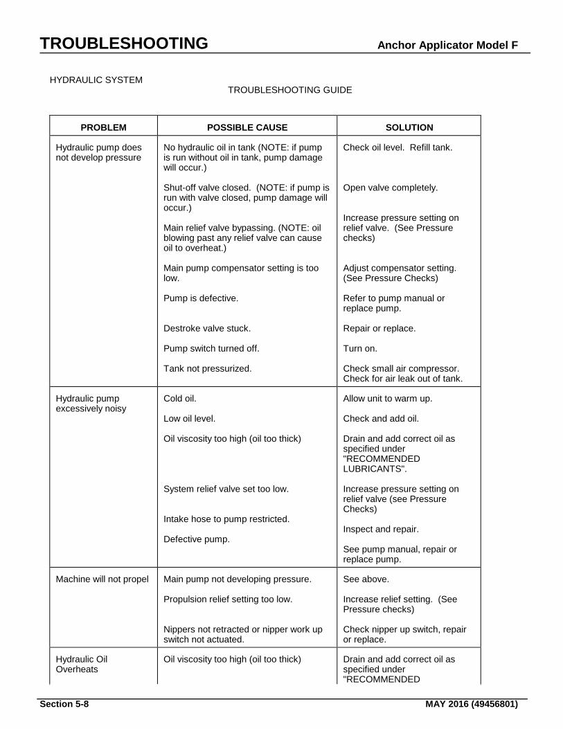
TROUBLESHOOTING Anchor Applicator Model F
Section 5-8 MAY 2016 (49456801)
HYDRAULIC SYSTEM TROUBLESHOOTING GUIDE
PROBLEM
POSSIBLE CAUSE
SOLUTION
Hydraulic pump does not develop pressure
No hydraulic oil in tank (NOTE: if pump is run without oil in tank, pump damage will occur.) Shut-off valve closed. (NOTE: if pump is run with valve closed, pump damage will occur.) Main relief valve bypassing. (NOTE: oil blowing past any relief valve can cause oil to overheat.) Main pump compensator setting is too low. Pump is defective. Destroke valve stuck. Pump switch turned off. Tank not pressurized.
Check oil level. Refill tank. Open valve completely. Increase pressure setting on relief valve. (See Pressure checks) Adjust compensator setting. (See Pressure Checks) Refer to pump manual or replace pump. Repair or replace. Turn on. Check small air compressor. Check for air leak out of tank.
Hydraulic pump excessively noisy
Cold oil. Low oil level. Oil viscosity too high (oil too thick) System relief valve set too low. Intake hose to pump restricted. Defective pump.
Allow unit to warm up. Check and add oil. Drain and add correct oil as specified under "RECOMMENDED LUBRICANTS". Increase pressure setting on relief valve (see Pressure Checks) Inspect and repair. See pump manual, repair or replace pump.
Machine will not propel
Main pump not developing pressure. Propulsion relief setting too low. Nippers not retracted or nipper work up switch not actuated.
See above. Increase relief setting. (See Pressure checks) Check nipper up switch, repair or replace.
Hydraulic Oil Overheats
Oil viscosity too high (oil too thick)
Drain and add correct oil as specified under "RECOMMENDED
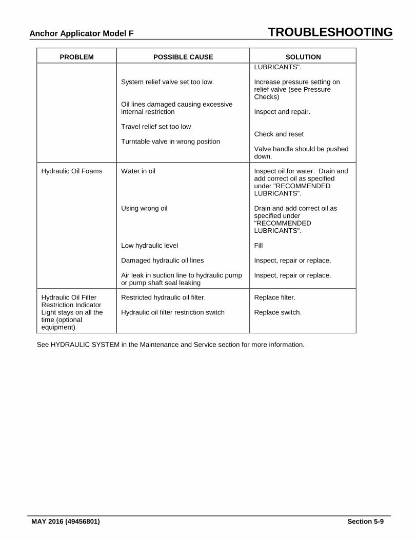
Anchor Applicator Model F TROUBLESHOOTING
MAY 2016 (49456801) Section 5-9
PROBLEM
POSSIBLE CAUSE
SOLUTION
System relief valve set too low. Oil lines damaged causing excessive internal restriction Travel relief set too low Turntable valve in wrong position
LUBRICANTS". Increase pressure setting on relief valve (see Pressure Checks) Inspect and repair. Check and reset Valve handle should be pushed down.
Hydraulic Oil Foams
Water in oil Using wrong oil Low hydraulic level Damaged hydraulic oil lines Air leak in suction line to hydraulic pump or pump shaft seal leaking
Inspect oil for water. Drain and add correct oil as specified under "RECOMMENDED LUBRICANTS". Drain and add correct oil as specified under "RECOMMENDED LUBRICANTS". Fill Inspect, repair or replace. Inspect, repair or replace.
Hydraulic Oil Filter Restriction Indicator Light stays on all the time (optional equipment)
Restricted hydraulic oil filter. Hydraulic oil filter restriction switch
Replace filter. Replace switch.
See HYDRAULIC SYSTEM in the Maintenance and Service section for more information.
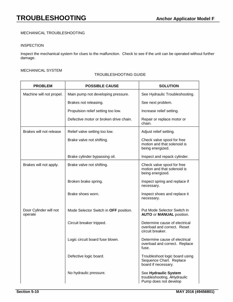
TROUBLESHOOTING Anchor Applicator Model F
Section 5-10 MAY 2016 (49456801)
MECHANICAL TROUBLESHOOTING INSPECTION Inspect the mechanical system for clues to the malfunction. Check to see if the unit can be operated without further damage. MECHANICAL SYSTEM TROUBLESHOOTING GUIDE
PROBLEM
POSSIBLE CAUSE
SOLUTION
Machine will not propel.
Main pump not developing pressure. Brakes not releasing. Propulsion relief setting too low. Defective motor or broken drive chain.
See Hydraulic Troubleshooting. See next problem. Increase relief setting. Repair or replace motor or chain.
Brakes will not release
Relief valve setting too low. Brake valve not shifting. Brake cylinder bypassing oil.
Adjust relief setting. Check valve spool for free motion and that solenoid is being energized. Inspect and repack cylinder.
Brakes will not apply.
Brake valve not shifting. Broken brake spring. Brake shoes worn.
Check valve spool for free motion and that solenoid is being energized. Inspect spring and replace if necessary. Inspect shoes and replace it necessary.
Door Cylinder will not operate
Mode Selector Switch in OFF position. Circuit breaker tripped. Logic circuit board fuse blown. Defective logic board. No hydraulic pressure.
Put Mode Selector Switch in AUTO or MANUAL position. Determine cause of electrical overload and correct. Reset circuit breaker. Determine cause of electrical overload and correct. Replace fuse. Troubleshoot logic board using Sequence Chart. Replace board if necessary. See Hydraulic System troubleshooting, AHydraulic Pump does not develop
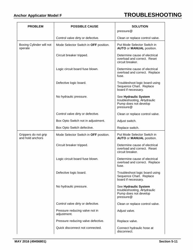
Anchor Applicator Model F TROUBLESHOOTING
MAY 2016 (49456801) Section 5-11
PROBLEM
POSSIBLE CAUSE
SOLUTION
Control valve dirty or defective.
pressure@ Clean or replace control valve.
Boxing Cylinder will not operate
Mode Selector Switch in OFF position. Circuit breaker tripped. Logic circuit board fuse blown. Defective logic board. No hydraulic pressure. Control valve dirty or defective. Box Opto Switch not in adjustment. Box Opto Switch defective.
Put Mode Selector Switch in AUTO or MANUAL position. Determine cause of electrical overload and correct. Reset circuit breaker. Determine cause of electrical overload and correct. Replace fuse. Troubleshoot logic board using Sequence Chart. Replace board if necessary. See Hydraulic System troubleshooting, AHydraulic Pump does not develop pressure@ Clean or replace control valve. Adjust switch. Replace switch.
Grippers do not grip and hold anchors
Mode Selector Switch in OFF position. Circuit breaker tripped. Logic circuit board fuse blown. Defective logic board. No hydraulic pressure. Control valve dirty or defective. Pressure reducing valve not in adjustment. Pressure reducing valve defective. Quick disconnect not connected.
Put Mode Selector Switch in AUTO or MANUAL position. Determine cause of electrical overload and correct. Reset circuit breaker. Determine cause of electrical overload and correct. Replace fuse. Troubleshoot logic board using Sequence Chart. Replace board if necessary. See Hydraulic System troubleshooting, AHydraulic Pump does not develop pressure@ Clean or replace control valve. Adjust valve. Replace valve. Connect hydraulic hose at disconnect.
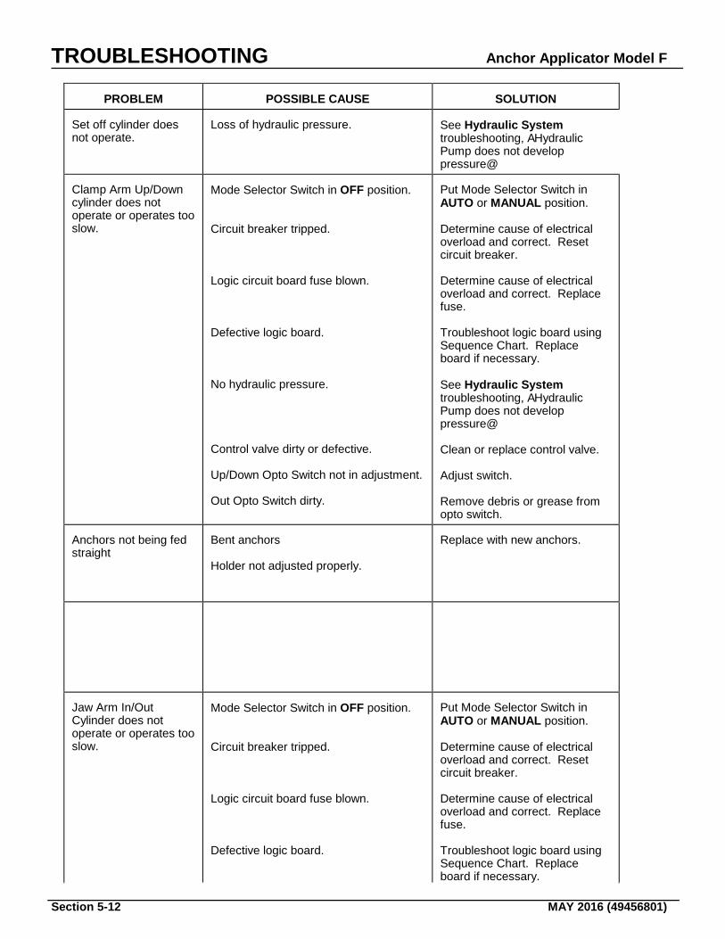
TROUBLESHOOTING Anchor Applicator Model F
Section 5-12 MAY 2016 (49456801)
PROBLEM
POSSIBLE CAUSE
SOLUTION
Set off cylinder does not operate.
Loss of hydraulic pressure.
See Hydraulic System troubleshooting, AHydraulic Pump does not develop pressure@
Clamp Arm Up/Down cylinder does not operate or operates too slow.
Mode Selector Switch in OFF position. Circuit breaker tripped. Logic circuit board fuse blown. Defective logic board. No hydraulic pressure. Control valve dirty or defective. Up/Down Opto Switch not in adjustment. Out Opto Switch dirty.
Put Mode Selector Switch in AUTO or MANUAL position. Determine cause of electrical overload and correct. Reset circuit breaker. Determine cause of electrical overload and correct. Replace fuse. Troubleshoot logic board using Sequence Chart. Replace board if necessary. See Hydraulic System troubleshooting, AHydraulic Pump does not develop pressure@ Clean or replace control valve. Adjust switch. Remove debris or grease from opto switch.
Anchors not being fed straight
Bent anchors Holder not adjusted properly.
Replace with new anchors.
Jaw Arm In/Out Cylinder does not operate or operates too slow.
Mode Selector Switch in OFF position. Circuit breaker tripped. Logic circuit board fuse blown. Defective logic board.
Put Mode Selector Switch in AUTO or MANUAL position. Determine cause of electrical overload and correct. Reset circuit breaker. Determine cause of electrical overload and correct. Replace fuse. Troubleshoot logic board using Sequence Chart. Replace board if necessary.
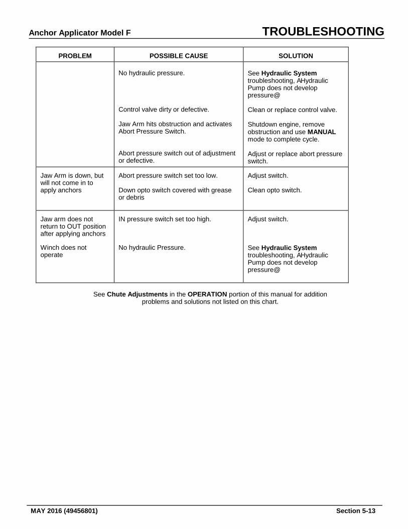
Anchor Applicator Model F TROUBLESHOOTING
MAY 2016 (49456801) Section 5-13
PROBLEM
POSSIBLE CAUSE
SOLUTION
No hydraulic pressure. Control valve dirty or defective. Jaw Arm hits obstruction and activates Abort Pressure Switch. Abort pressure switch out of adjustment or defective.
See Hydraulic System troubleshooting, AHydraulic Pump does not develop pressure@ Clean or replace control valve. Shutdown engine, remove obstruction and use MANUAL mode to complete cycle. Adjust or replace abort pressure switch.
Jaw Arm is down, but will not come in to apply anchors
Abort pressure switch set too low. Down opto switch covered with grease or debris
Adjust switch. Clean opto switch.
Jaw arm does not return to OUT position after applying anchors
IN pressure switch set too high.
Adjust switch.
Winch does not operate
No hydraulic Pressure.
See Hydraulic System troubleshooting, AHydraulic Pump does not develop pressure@
See Chute Adjustments in the OPERATION portion of this manual for addition problems and solutions not listed on this chart.

TROUBLESHOOTING Anchor Applicator Model F
Section 5-14 MAY 2016 (49456801)