Karsnitz Instructor PPT Ch 08 - Technical Drawingpages.jh.edu/~maliyou1/EngDesign/Karsnitz...
22
12/1/2017 1 Chapter 8 Technical Drawing Technical Drawings • Multiview drawings – Also called three-view drawings – Simple objects take three views • Front, top, one side • Title block – Identifies who did the design – Gives date, scale, and tolerance
Transcript of Karsnitz Instructor PPT Ch 08 - Technical Drawingpages.jh.edu/~maliyou1/EngDesign/Karsnitz...

12/1/2017
1
Chapter 8
Technical Drawing
Technical Drawings
• Multiview drawings– Also called three-view drawings
– Simple objects take three views• Front, top, one side
• Title block– Identifies who did the design
– Gives date, scale, and tolerance
12/1/2017
2
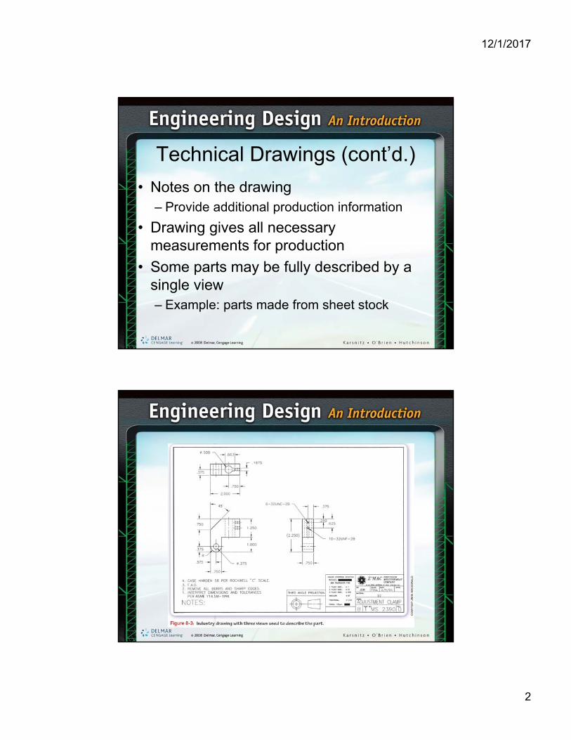
Technical Drawings (cont’d.)
• Notes on the drawing– Provide additional production information
• Drawing gives all necessary measurements for production
• Some parts may be fully described by a single view– Example: parts made from sheet stock
12/1/2017
3
Technical Drawings (cont’d.)
• Two views are all that is needed for some circular parts
• Some parts may need more than three views– Interior structure not perpendicular to one of
the normal planes
Technical Drawings (cont’d.)
• Most drawings today are done by computer
• Orthographic drawings– Precise
– Answer all design and production questions
12/1/2017
4
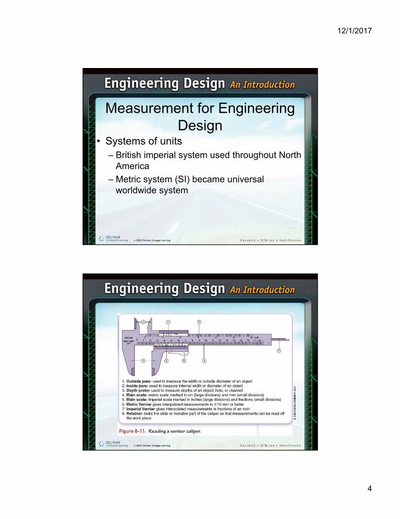
Measurement for Engineering Design
• Systems of units– British imperial system used throughout North
America
– Metric system (SI) became universal worldwide system
12/1/2017
5
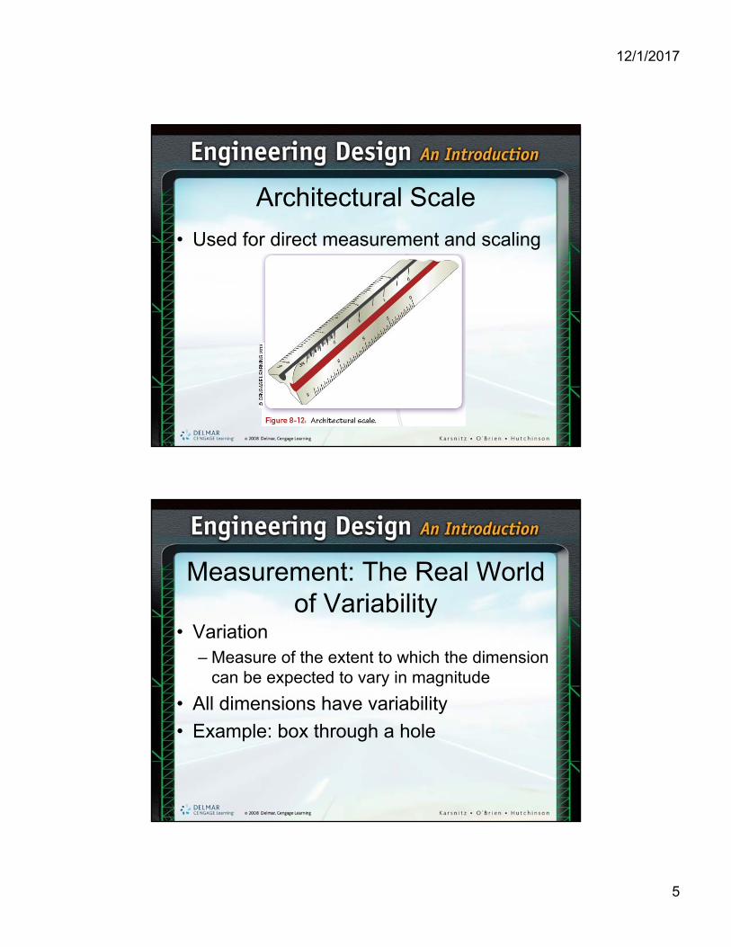
Architectural Scale
• Used for direct measurement and scaling
Measurement: The Real World of Variability
• Variation– Measure of the extent to which the dimension
can be expected to vary in magnitude
• All dimensions have variability
• Example: box through a hole

12/1/2017
6
Accuracy and Precision
• Accuracy– Degree of conformity of a measured or
calculated value to its actual value
• Precision– Degree to which several measurements or
calculations show the same result
– Also known as repeatability or reproducibility

12/1/2017
7
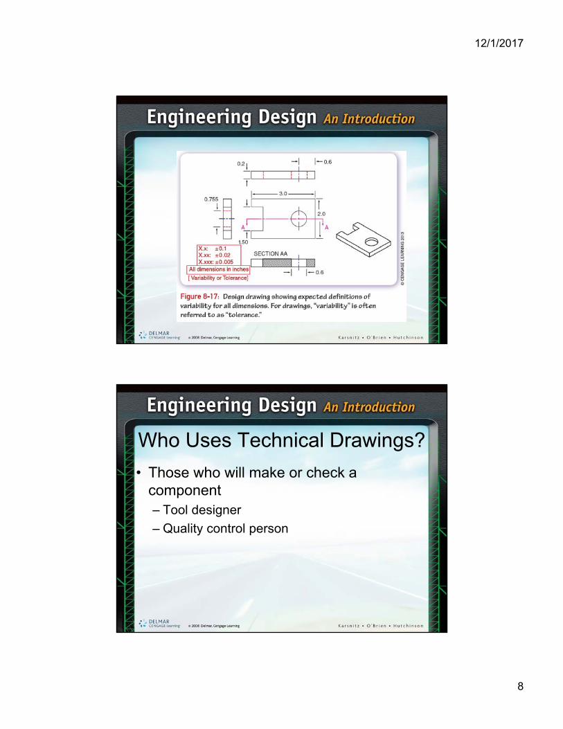
Simple Rules for Variability of Measurement
• Variability typically referred to as tolerance
• When using a physical measuring device:– Take a fraction of the smallest viewable
dimension as the variability
• When using a commercial instrument:– Use the published accuracy
12/1/2017
8
Who Uses Technical Drawings?
• Those who will make or check a component– Tool designer
– Quality control person
12/1/2017
9
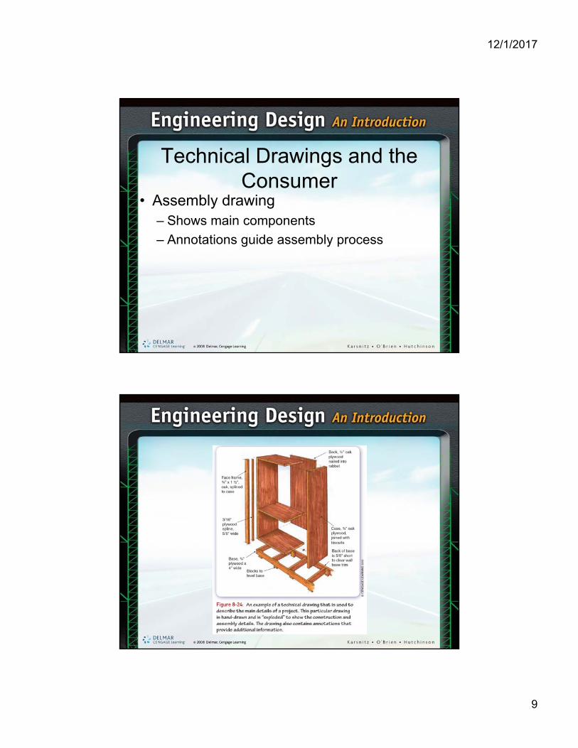
Technical Drawings and the Consumer
• Assembly drawing– Shows main components
– Annotations guide assembly process
12/1/2017
10
Technical Drawing Standards
• Convention– Refers to the way something is usually done
• American National Standards Institute (ANSI)– Established standards for technical drawings
– Used in the U.S., Canada, and other countries
Technical Drawing Standards (cont’d.)
• International Organization for Standardization (ISO)– Similar standards based on the metric system
– Used outside of the U.S. and Canada
12/1/2017
11
Technical Drawings and the Engineering Process
• Primary purpose of a technical drawing– Communicate a solution between members of
design and production teams
• Revision of drawings– Done by engineering change notice (ECN)
Drafting and CAD
• History– Drawings made on vellum using pencil and
ink
– AutoCAD and similar programs became popular in the 1980s
– Solid modeling software used today to create 3-D models of parts

12/1/2017
12
Isometric and Oblique Pictorial Drawings
• Projection– Exact representation of a 3-D object projected
onto a plane from a specific location
• Common projections– Isometric
– Dimetric
– Trimetric
12/1/2017
13
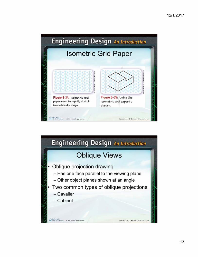
Isometric Grid Paper
Oblique Views
• Oblique projection drawing– Has one face parallel to the viewing plane
– Other object planes shown at an angle
• Two common types of oblique projections– Cavalier
– Cabinet

12/1/2017
14
Orthographic Drawing and Sketching
• Arrangement of views– First-angle projection
– Third-angle projection
• Angle of projection– Refers to the arrangement of views in an
orthographic drawing
Envisioning an Object in Three Views
• Spatial ability– Ability to visualize sides of a complex object
– Developed through practice

12/1/2017
15
Spacing Between Views
• No standards apply to spaces between views
• Dimensioning guidelines– Dimensions should be placed between the
views• Whenever possible
12/1/2017
16
Scale
• Most objects cannot be drawn true to size
• Scale– Indicates relationship between drawing and
actual size
– Should be clearly marked in the title block
Line Conventions
• Object lines– Outline and detail an object’s shape
• Construction lines– Used to lay out drawings and sketches
• Hidden lines– Dashed lines
– Used to represent edge of a surface hidden from view
12/1/2017
17
Line Conventions (cont’d.)
• Centerlines– Used to identify the location of a hole or arc
center
• Extension lines– Used to extend edges of an object so they
may be located with dimension lines
• Dimension lines– Used to indicate size of an object or feature
Section Views
• Provides view of an object as if it were cut by a saw
• Cutting plane line– Located in the top view
– Represents the location of the cutting plane passing through the object

12/1/2017
18
Auxiliary Views
• Used to show a surface not parallel to any of the principal view planes
• Projection line– Horizontal or vertical line that can be used to
locate entities in an adjacent view
12/1/2017
19
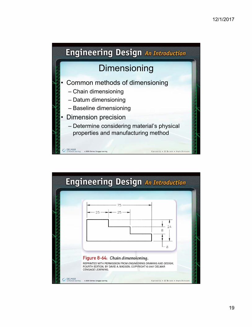
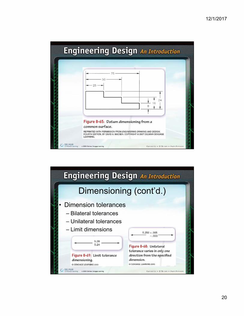
Dimensioning
• Common methods of dimensioning– Chain dimensioning
– Datum dimensioning
– Baseline dimensioning
• Dimension precision– Determine considering material’s physical
properties and manufacturing method
12/1/2017
20
Dimensioning (cont’d.)
• Dimension tolerances– Bilateral tolerances
– Unilateral tolerances
– Limit dimensions

12/1/2017
21
Dimensioning (cont’d.)
• Types of features that must be dimensioned– Hole
– Fillet
– Round
– Chamfer
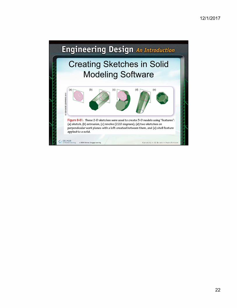
Computer-Aided Design
• Parametric modeling– CAD modeling method
– Each feature uses a parameter to define the size and geometry
– Creates relationships between features
• Solid modeling– Mathematically describes both interior and
exterior of an object
12/1/2017
22
Creating Sketches in Solid Modeling Software