KA07 manual - Velleman · Add a real time clock shield to your projects to ensure ... provides...
12
Add a real time clock shield to your projects to ensure accurate and easy timekeeping. While the shield keeps track of time and date, the controller can focus on other tasks. ILLUSTRATED ASSEMBLY MANUAL HKA07IP’1 KA07 RTC shield for Arduino ® Features • based on Maxim-Dallas DS1307 IC • counts seconds, minutes, hours, date of month, day of the week, year and leap-year • 12 or 24h system selectable • AM/PM indication • large user community • requires 1 Arduino UNO™ (not included) • stackable design: the shield can be stacked with other shields Specifications • I2C interface • accuracy: 20ppm (depends on crystal) • power consumption: 1.5mA • with backup battery holder (500nA when running on battery) • dimensions: 68 x 53mm / 2.67 x 2.08”
Transcript of KA07 manual - Velleman · Add a real time clock shield to your projects to ensure ... provides...

Add a real time clock shield to your projects to ensure accurate and easy timekeeping. While the shield keeps track of time and date, the controller can focus on other tasks.
ILLUSTRATED ASSEMBLY MANUAL HKA07IP’1ILLUSTRATED ASSEMBLY MANUAL HKA07IP’1
KA07
RTC shield for Arduino®
Features• based on Maxim-Dallas DS1307 IC• counts seconds, minutes, hours, date of month, day of the week, year and leap-year• 12 or 24h system selectable• AM/PM indication• large user community• requires 1 Arduino UNO™ (not included)• stackable design: the shield can be stacked with other shields
Specifi cations• I2C interface• accuracy: 20ppm (depends on crystal)• power consumption: 1.5mA• with backup battery holder (500nA when running on battery)• dimensions: 68 x 53mm / 2.67 x 2.08”

ForumForumParticipate our Velleman Projects Forum
Subscribing our newsletter?, visit www.vellemanprojects.eu

Velleman N.V.Legen Heirweg 33
9890 Gavere(België)
- 5 -
assembly hints
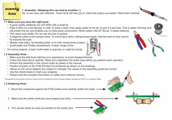
1. Assembly (Skipping this can lead to troubles ! )Ok, so we have your attention. These hints will help you to make this project successful. Read them carefully.
1.1 Make sure you have the right tools:• A good quality soldering iron (25-40W) with a small tip.• Wipe it often on a wet sponge or cloth, to keep it clean; then apply solder to the tip, to give it a wet look. This is called ‘thinning’ and
will protect the tip, and enables you to make good connections. When solder rolls off the tip, it needs cleaning.• Thin raisin-core solder. Do not use any fl ux or grease.• A diagonal cutter to trim excess wires. To avoid injury when cutting excess leads, hold the lead so they cannot
fl y towards the eyes.• Needle nose pliers, for bending leads, or to hold components in place.• Small blade and Phillips screwdrivers. A basic range is fi ne.
For some projects, a basic multi-meter is required, or might be handy.
1.2 Assembly Hints :• Make sure the skill level matches your experience, to avoid disappointments.• Follow the instructions carefully. Read and understand the entire step before you perform each operation. • Perform the assembly in the correct order as stated in this manual.• Position all parts on the PCB (Printed Circuit Board) as shown on the drawings. • Values on the circuit diagram are subject to changes, the values in this assembly guide are correct*.• Use the check-boxes to mark your progress.• Please read the included information on safety and customer service.
* Typographical inaccuracies excluded. Always look for possible last minute manual updates, indicated as ‘NOTE’ on a separate leafl et.
1.3 Soldering Hints :
1. Mount the component against the PCB surface and carefully solder the leads.
2. Make sure the solder joints are cone-shaped and shiny.
3. Trim excess leads as close as possible to the solder joint.
Make sure the skill level matches your experience, to avoid disappointments.

- 5 -
DO NOT BLINDLY FOLLOW THE ORDER OF THE COMPONENTS ON THE TAPE. ALWAYS CHECK THEIR
VALUE ON THE PARTS LIST!
1. Assembly (Skipping this can lead to troubles ! )Ok, so we have your attention. These hints will help you to make this project successful. Read them carefully.
1.1 Make sure you have the right tools:• A good quality soldering iron (25-40W) with a small tip.• Wipe it often on a wet sponge or cloth, to keep it clean; then apply solder to the tip, to give it a wet look. This is called ‘thinning’ and
will protect the tip, and enables you to make good connections. When solder rolls off the tip, it needs cleaning.• Thin raisin-core solder. Do not use any fl ux or grease.• A diagonal cutter to trim excess wires. To avoid injury when cutting excess leads, hold the lead so they cannot
fl y towards the eyes.• Needle nose pliers, for bending leads, or to hold components in place.• Small blade and Phillips screwdrivers. A basic range is fi ne.
For some projects, a basic multi-meter is required, or might be handy.
1.2 Assembly Hints :• Make sure the skill level matches your experience, to avoid disappointments.• Follow the instructions carefully. Read and understand the entire step before you perform each operation. • Perform the assembly in the correct order as stated in this manual.• Position all parts on the PCB (Printed Circuit Board) as shown on the drawings. • Values on the circuit diagram are subject to changes, the values in this assembly guide are correct*.• Use the check-boxes to mark your progress.• Please read the included information on safety and customer service.
* Typographical inaccuracies excluded. Always look for possible last minute manual updates, indicated as ‘NOTE’ on a separate leafl et.
1.3 Soldering Hints :
1. Mount the component against the PCB surface and carefully solder the leads.
2. Make sure the solder joints are cone-shaped and shiny.
3. Trim excess leads as close as possible to the solder joint.

- 6 - - 7 -
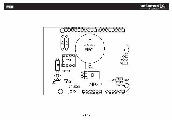
Construction
R1: 470 (4 - 7 - 1 - B) R2: 2K2 (2 - 2 - 2 - B) R3: 2K2 (2 - 2 - 2 - B)
R...
Resistors 1
IC-socket4
Ceramic capacitor
Crystal
9
2
3
IC1: 8p
C1: 100nF (104)
X1: 32.768 MHz
C2: 100µF
JP1: Enable SQW output JP2: I2C interface JP3: I2C interface
LED7
Male headers8
Battery holder6
Electrolytic capacitor5
CONSTRUCTIONI
CR2032 VBAT SK6: 2 x 3p
c...
c...
Crystal
X1: 32.768 MHz
Watch the polarity!
LD1: Green (5mm)C (-)
Watch the polarity!
Watch the position of the notch!
2 x 8p
2
3
Solder
1
Jumper wire
A
B

- 6 - - 7 -
Construction
Female headers9
JP1: Enable SQW output JP2: I2C interface JP3: I2C interface
LED
Male headers
SK6: 2 x 3p
2 x 6p
LD1: Green (5mm)
2 x 8p
Do not cut the connector pins!
2
3
Solder
1 2
3
Solder
1
IC10
Watch the position of the notch!
IC1: DS1307
A
B

- 8 - - 9 -
General information
General informationII
Back-up battery: provides power to the shield when the Arduino Uno is not active.
Place jumpers JP2 and JP3 when using the shield with the Arduino Uno rev2 or Arduino 2009.
The IC drives an LED, which blinks at the same frequency as the SQW output. Select via jumper JP1 whether this signal goes to pin A3 of the shield.
The IC drives an LED, which blinks at the same frequency as the SQW output. Select via jumper JP1 whether this signal goes to pin A3 of the shield.
The library allows you to manage the frequency of the LED. Use command RTC.sqw(x). Values for ‘x’:
0: LED off1: 1 Hz2: 4096 Hz3: 8192 Hz4: 32768 Hz
X11
X22
VBAT3
GND4
VCC 8
SQW/OUT 7
SCL 6
SDA 5
DS1307
IC1
VCC
LED5MMLD1
VCCGND
SCL
VCC
A5
A4
GNDGND
SDA
VCC
GND
A5A4A3
GND
SDA
SCL
A3
GND
470R1
100nC1
100ÁC2
32.768KX1
CR2032BATTERY
SQWJP1
JP2 JP3
2k2R2
2k2R3
ARDUINO UNO
/RESE
T0
3V1
5V2
GND2
3
GND1
4
VIN5
A06
A17
A28
A39
A4/SD
A10
A5/SC
L11
D012
D113
D214
D315
D416
D517
D618
D719
D820
D921
D10
22D1
123
D13
25
D12
24
GND
26
SDA
28SC
L29
30
MISO 31
MOSI 32
SCK 33
GND 34
RESET 35
AREF
27
ARDUINO UNO*
Download the library from www.vellemanprojects.eu.

- 8 - - 9 -
Schematic diagram
General information
Back-up battery: provides power to the shield when the Arduino Uno is not active.
Place jumpers JP2 and JP3 when using the shield with the Arduino Uno rev2 or Arduino 2009. X11
X22
VBAT3
GND4
VCC 8
SQW/OUT 7
SCL 6
SDA 5
DS1307
IC1
VCC
LED5MMLD1
VCCGND
SCL
VCC
A5
A4
GNDGND
SDA
VCC
GND
A5A4A3
GND
SDA
SCL
A3
GND
470R1
100nC1
100ÁC2
32.768KX1
CR2032BATTERY
SQWJP1
JP2 JP3
2k2R2
2k2R3
ARDUINO UNO
/RESE
T0
3V1
5V2
GND2
3
GND1
4
VIN5
A06
A17
A28
A39
A4/SD
A10
A5/SC
L11
D012
D113
D214
D315
D416
D517
D618
D719
D820
D921
D10
22D1
123
D13
25
D12
24
GND
26
SDA
28SC
L29
30
MISO 31
MOSI 32
SCK 33
GND 34
RESET 35
AREF
27
ARDUINO UNO*
- 10 -
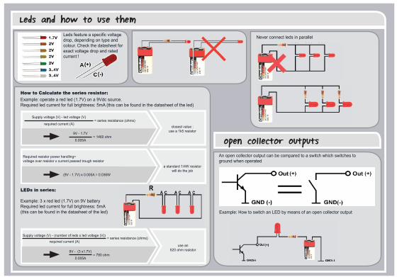
PCB Leds and how to use them
- 10 -
Supply voltage (V) - led voltage (V)
required current (A)= series resistance (ohms)
required current (A)= series resistance (ohms)
Required resistor power handling= voltage over resistor x current passed trough resistor
9V - 1.7V
0.005A= 1460 ohm
9V - (3 x1.7V)
0.005A= 780 ohm
(9V - 1.7V) x 0.005A = 0.036W
closest value : use a 1k5 resistor
use an 820 ohm resistor
a standard 1/4W resistor will do the job
Supply voltage (V) - (number of leds x led voltage (V))
How to Calculate the series resistor:Example: operate a red led (1.7V) on a 9Vdc source. Required led current for full brightness: 5mA (this can be found in the datasheet of the led)
LEDs in series:
Example: 3 x red led (1.7V) on 9V battery Required led current for full brightness: 5mA (this can be found in the datasheet of the led)
Leds feature a specifi c voltage drop, depending on type and colour. Check the datasheet for exact voltage drop and rated current !
Never connect leds in parallel
Leds and how to use them
An open collector output can be compared to a switch which switches to ground when operated
Example: How to switch an LED by means of an open collector output
open collector outputs

The new Velleman Projects catalogue is now available. Download your copy here:
www.vellemanprojects.eu
Modifi cations and typographical errors reserved - © Velleman nv. HKA07’IP Velleman NV, Legen Heirweg 33 - 9890 Gavere.