Juniper Networks TX Matrix testing (including STM … Networks TX Matrix testing (including STM-256...
43
1 Hands-on evaluation of new routers and switches (activity 9.7) Juniper Networks TX Matrix testing (including STM-256 card and DWDM PIC) TF-NGN Ljubljana, 4-5 July 2006 Marcin Garstka [email protected]
-
Upload
nguyenngoc -
Category
Documents
-
view
228 -
download
3
Transcript of Juniper Networks TX Matrix testing (including STM … Networks TX Matrix testing (including STM-256...

1
Hands-on evaluation of new routers and switches
(activity 9.7)
Juniper Networks TX Matrix testing(including STM-256 card and DWDM PIC)
TF-NGN
Ljubljana, 4-5 July 2006
Marcin Garstka

2
Motto:
To prove that TX is really a singlerouter in multiple chassis.

3
Juniper Networks TX Matrix testing:• 20-21 June 2006• Amsterdam, Juniper POC lab• Participants:
– Marcin Garstka (PSNC)– Josef Voytech (CESNET)– Carsten Rosche (Fraunhofer-IMK Sankt Augustin)– Cătălin Meiroşu (Terena)– Jean-Marc Uze (Juniper)– Holger Metschulat (Juniper)– Andre Stiphout (Juniper POC lab)
4
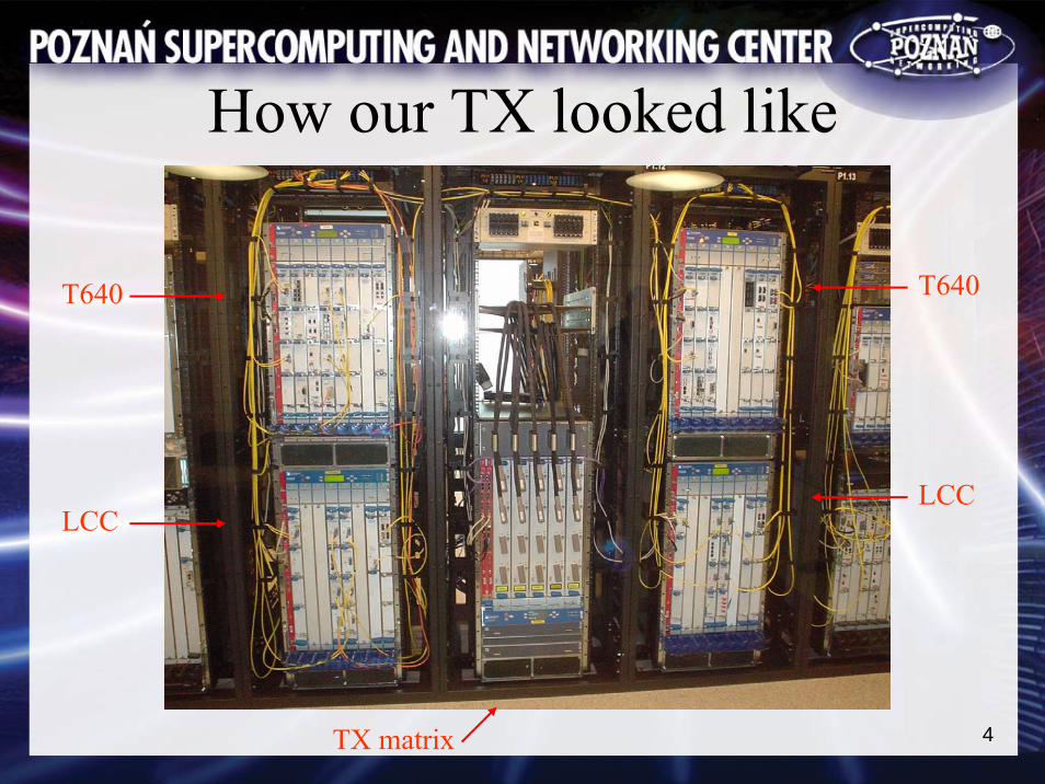
How our TX looked like
TX matrix
LCCLCC
T640 T640

5
How hard we worked

6
Our group with TX
7
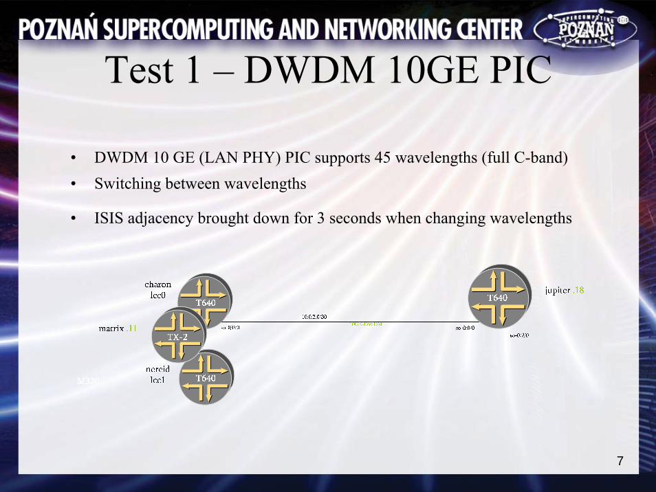
Test 1 – DWDM 10GE PIC
• DWDM 10 GE (LAN PHY) PIC supports 45 wavelengths (full C-band)• Switching between wavelengths
• ISIS adjacency brought down for 3 seconds when changing wavelengths

8
Test 1 – DWDM 10GE PIC – configuration
andre@matrix# set interfaces ge-0/0/0 optics-options wavelength 1549.32
[edit]
andre@matrix# show interfaces ge-0/0/0
description matrix-jupiter-DWDM;
optics-options {
wavelength 1549.32;
}
9
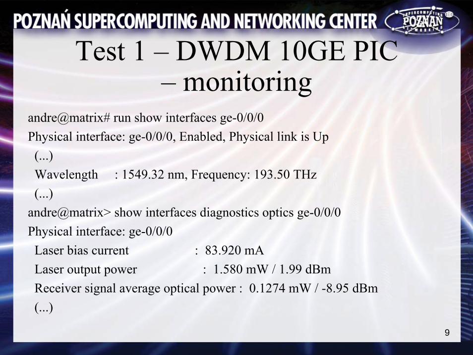
Test 1 – DWDM 10GE PIC – monitoring
andre@matrix# run show interfaces ge-0/0/0 Physical interface: ge-0/0/0, Enabled, Physical link is Up(...)Wavelength : 1549.32 nm, Frequency: 193.50 THz(...)
andre@matrix> show interfaces diagnostics optics ge-0/0/0 Physical interface: ge-0/0/0
Laser bias current : 83.920 mA Laser output power : 1.580 mW / 1.99 dBmReceiver signal average optical power : 0.1274 mW / -8.95 dBm(...)

10
Test 2 – STM-256 card test
• Eight 10Gps streams generated from Agilent testers, transmitted over STM-256 link between two routers (four streams in one direction, for in the other)
• IPv4 test with packet size 40B (said to be the worst case for many routers)
• IPv6 test with packet size 60B• IPv4 in MPLS test with packet size 40B

11
Test 2 – lab setup
matrix .11
jupiter .18
vega .200
nereidlcc1
charonlcc0
so-6/0/0 so-6/0/0STM256-SR2
so-8/0/0
10.0.1.0/30
STM64-SR2
so-0/2/0
10.0.3.0/30
so-0/2/0
STM64-SR2
10.0.4.0/30
so-0/0/0
so-3
/0/0
STM
64
201/1
10.2
0.11
.0/3
0
so-3
/2/0
STM
64
202/2
10.2
0.21
.0/3
0
so-4
/0/0
STM
64
203/2
10.2
0.31
.0/3
0
so-4
/2/0
STM
64
204/2
10.2
0.41
.0/3
0
so-3
/0/0
STM
64
101/1
10.1
0.11
.0/3
0
so-3
/2/0
STM
64
102/1
10.1
0.21
.0/3
0
so-4
/0/0
STM
64
103/1
10.1
0.31
.0/3
0
so-4
/2/0
STM
64
104/1
10.1
0.41
.0/3
0

12
No packet loss
Sent and received traffic
No packet loss
Test 2 – sample results (IPv4 test)

13
Test 2 – sample graphsGraphs generated by MG-SOFT from statistics gathered from one of the routers (statistics in one direction)
All statistics on IP or MPLS leyer (without PPP/HDLC headers)
Max bandwidth in theory:
• Sonet (with overheads) – 39,813Mbps
• For IPv4 (40B packets) – 31,296 Mbps
• For IPv6 (60B packets) – 35,486 Mbps
• For MPLS (40B packets) – 31,828 Mbps
IPv4
IPv6
MPLS

14
Test 2 – with filtering etcTests with TCP packets, variable packet size (60-256B), variable TCP ports
100,000 BGP prefixes inserted from each Agilent (800,000 prefixes total)
Tests:
• Packet filtering (1000 terms, applied in and out, only negative hits, filteringon IP addresses)
• Packet counting (1000 counters, counting on TCP ports)
• Filter based forwarding (1000 terms with only negative hits, last hit positive,filtering on IP addresses)
Results:
• No impact on bandwidth
• A few microsecond increase of latency
15
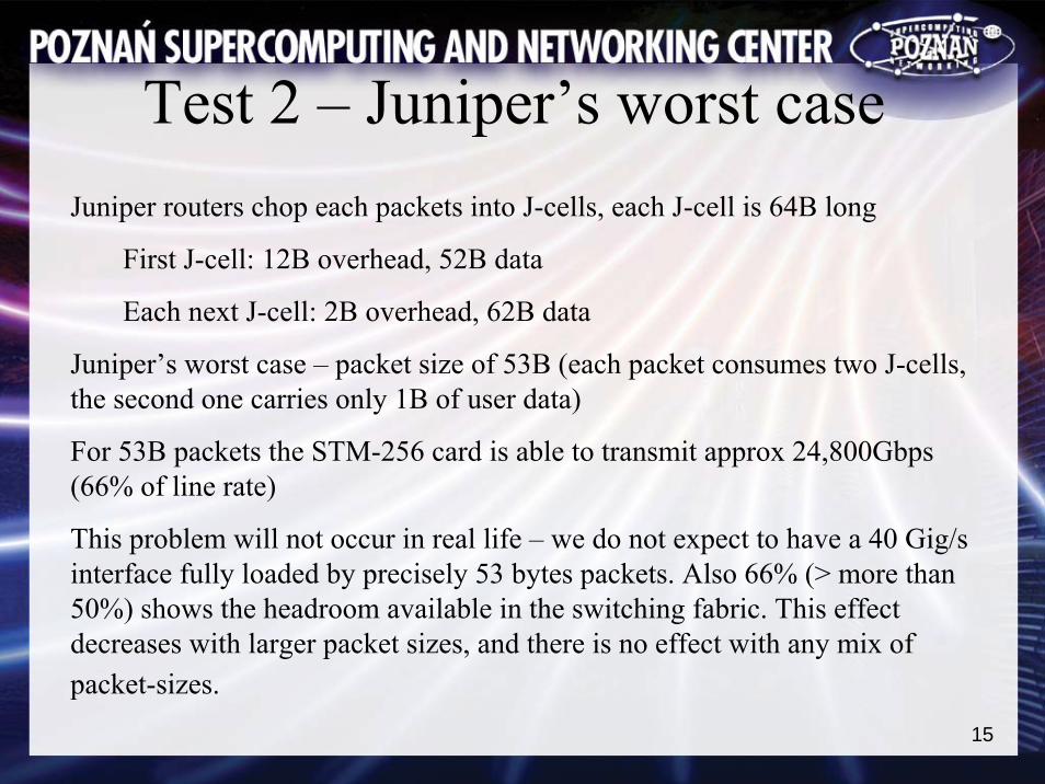
Test 2 – Juniper’s worst caseJuniper routers chop each packets into J-cells, each J-cell is 64B long
First J-cell: 12B overhead, 52B data
Each next J-cell: 2B overhead, 62B data
Juniper’s worst case – packet size of 53B (each packet consumes two J-cells, the second one carries only 1B of user data)
For 53B packets the STM-256 card is able to transmit approx 24,800Gbps (66% of line rate)
This problem will not occur in real life – we do not expect to have a 40 Gig/sinterface fully loaded by precisely 53 bytes packets. Also 66% (> more than50%) shows the headroom available in the switching fabric. This effect decreases with larger packet sizes, and there is no effect with any mix of packet-sizes.

16
Test 2 – results• STM-256 card tested with IPv4, IPv6 and MPLS packets
• Line rate even for short packets
• Packet filters, packet counters and policy based routing do not affect bandwidth

17
Test 3 – TX reliability• Failover between TX Routing Engines
• LCC (Line Card Chassis) switching off and on so
-3/0
/0ST
M64
10.1
0.11
.0/3
0
so-3
/2/0
STM
64
10.1
0.21
.0/3
0
so-11 /2/0STM
64
1 0.20.21.0/30
so-11/0/0ST M
64
10.20.11.0 /30

18
Test 3 – TX reliability• The active Routing Engine was removed from the TX
• The router switched to the other Routing Engine
• Packet loss was monitored during the switchover
• No packet loss detected – non-stop forwarding
• Graceful RE switchover (graceful restart must be supported by adjacent/neighbouring routers)
• All routing protocols adjacencies went down and were re-established on the other Routing Engine
• Forwarding plane was not affected – non-stop forwarding
19
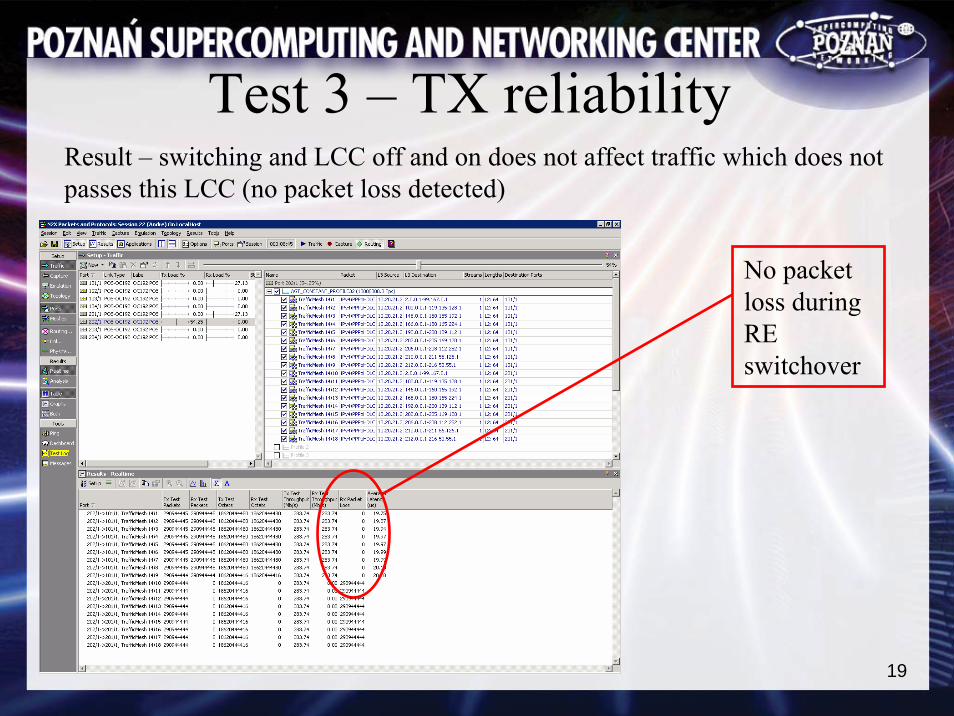
Test 3 – TX reliability
No packet loss during RE switchover
Result – switching and LCC off and on does not affect traffic which does not passes this LCC (no packet loss detected)
20
Test 4 – forwarding planeLatency measured when packets are transmitted:
• between two PICs on the same PFE
• between two PICs on different PFEs, the same FPC
• between two PICs on different FPCs, the same line-card chassis
• between two PICs on different line-card chassis
Test for IPv4, IPv6 and MPLS

21
Test 4 – lab setupso
-4/1
/0ST
M64
10.1
0.11
.0/3
0
so-4
/3/0
STM
64
10.1
0.21
.0/3
0
so-4
/0/0
STM
64
10.1
0.31
.0/3
0
so-4
/2/0
STM
64
10.1
0.41
.0/3
0
so- 11/2/0STM
6 4
10.20.21.0/30
so-11/0/0ST M
64
10.20.11.0 /30
so-4
/1/0
STM
64
10.1
0.11
.0/3
0
so-4
/3/0
STM
64
10.1
0.21
.0/3
0
so-4
/0/0
STM
64
10.1
0.31
.0/3
0
so-4
/2/0
STM
64
10.1
0.41
.0/3
0
s o-12/2/0STM
64
10.20.41.0/3 0
so-12/0/0S TM
64
10.20.31 .0/30
matrix .11
nereidlcc1
charonlcc0
so-3
/0/0
STM
64
101/1
10.1
0.11
.0/3
0
so-3
/2/0
STM
64
102/1
10.1
0.21
.0/3
0
so-4
/0/0
STM
64
103/1
10.1
0.31
.0/3
0
so-4
/2/0
STM
64
104/1
10.1
0.41
.0/3
0
Intra-PFE, Intra-FPC Inter-FPC Inter-LCC

22
Test 4 – forwarding planeAverage latency in microseconds, measured by Agilent testers
IPv4 IPv6 MPLSSame PFE 15 14.2 14.6Different PFEs, same FPC 21.6 24.3 not tested*Different FPCs, same LCC 21.8 20.7 21.2Different LCCs 21.3 20.8 21
Results:
• Shorter latency in the ‘Same PFE’ test is as a result of packet processing on PFE (without transmitting to the central switching matrix).
• In other cases latency do not depend on whether packets are received and transmitted on the same LCC or on different LCCs (in all cases packets are processed by the central switching matrix).
* One MPLS test was missed unintentionally.

23
Test 5 – convergance of routing protocols
5a – BGP convergence inter- and intra-LCC
5b – ISIS convergence inter- and intra-LCC
5c –indirect next-hop for iBGP
For all tests the protocols have been configured with default behaviours,except spf-delay which was brought down from default 200ms to 50ms (minimum)

24
Test 5 – BGP convergence
so-3
/2/0
STM
64
10.2
0.21
.0/3
0
so-3
/0/0
STM
64
10.1
0.11
.0/3
0
so-2/0/0STM
64
10.20.11.0/30
For intra-LCC test
For inter-LCC test
The same prefixes injected from 202/1 and 201/1 (500,000 prefixes/16 – /24)
iBGP between routers, eBGP to Agilent testers
Traffic generated from 101/1 and monitored on 202/1 and 201/1
Matrix has higher LP for jupiter – prefers routes from jupiter and sends traffic to 202/1

25
Test 5 – BGP convergence275,000 routes (/24) from 202/1 withdrawn and then readvertised
Convergence time measured
Test repeated in inter-LCC and intra-LCC configuration

26
Test 5 – BGP convergence
advertise – single chassis – 49 sec advertise – multiple chassis – 47 sec
withdraw – single chassis – 56 sec withdraw – multiple chassis – 57 sec

27
Test 5 – ISIS convergence
so-3
/2/0
STM
64
10.2
0.21
.0/3
0
so-3
/0/0
STM
64
10.1
0.11
.0/3
0
so-2/0/0STM
64
10.20.11.0/30
For intra-LCC test
For inter-LCC test
Testers 202/1 and 201/1 emulate 5 routers with 5000 routes each (the same routes on both testers)
Jupiter and vega prefer routes from locally connected testers
Matrix prefers routes from jupiter
Traffic generated from 101/1 and monitored on 202/1 and 201/1
Matrix sends traffic to 202/1
28
Test 5 – ISIS convergenceEmulate link failure between vega and tester
ISIS convergence time measured
Test repeated in inter-LCC and intra-LCC configuration

29
Test 5 – ISIS convergence
Link up – single chassis – 3 sec link up – multiple chassis – 3 sec
Link failure – single chassis – 4 sec link failure – multiple chassis – 3 sec

30
Test 5 – BGP and ISIS convergenceResults – times for intra- and inter-LCC convergence are very similar.
Explanation – routing information is always processed by TX.

31
Test 5 – indirect next-hop for iBGPIndirect next-hop convergence is possible when the protocol (BGP) next-hopdoes not change, i.e. there is only an IGP failure, somewhere in the network
When the ISIS/OSPF next hop changes (because of topology change) the BGP routes do not need to be removed from routing table and installed again – convergance is much faster
Convergence time in our test (with 500,000 routes):
• eBGP (without indirect next-hop) – 80 sec
• iBGP (with indirect next-hop) – 10 sec

32
Test 6 – Bidirectional Forwarding Detection (BFD)
Faster convergence of routing protocol when interface state do not change to down, e.g. link failure between two Ethernet switches (or sometimes SDH switches with Ethernet client interfaces)
Shorter dead times than with routing protocols
Can be used with BGP (single hop eBGP only), ISIS, OSPF, static route, RIP, LDP, RSVP based LDP
33
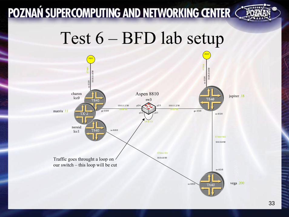
Test 6 – BFD lab setup
matrix .11
jupiter .18
vega .200
nereidlcc1
charonlcc0
so-8/0/0
10.0.11.2/30
ge-3/3/010GE-SX
STM64-SR2
so-0/2/0
10.0.3.0/30
ge-3/3/0so-0/2/0
STM64-SR2
10.0.4.0/30
so-0/0/0
so-3
/2/0
STM
64
202/2
10.2
0.21
.0/3
0
so-3
/2/0
STM
64
102/1
10.1
0.21
.0/3
0
p2/3p2/4
p2/2 p2/110GE-SX
10GE-LX
sw310.0.11.1/30
Traffic goes throught a loop on our switch – this loop will be cut
Aspen 8810

34
Test 6 – BFD testISIS with default hello time – 9 seconds
Expected time for ISIS to detect the failure of the loop on switch – between 18 and 27 seconds
Test results:Without BFD (22 sec recovery,20,000,000 packets lost
With BFD (0.3 sec recovery,304,000 packets lost
35
Test 6 – BFD test resultsBFD makes routing protocol convergence much faster
One recommended value with current implementation is to use a detection-time of 250 ms for up to 100 sessions
36
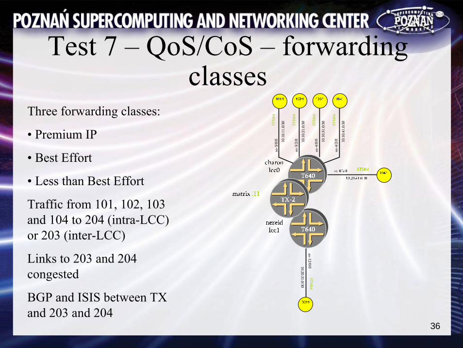
Test 7 – QoS/CoS – forwarding classes
Three forwarding classes:
• Premium IP
• Best Effort
• Less than Best Effort
Traffic from 101, 102, 103 and 104 to 204 (intra-LCC) or 203 (inter-LCC)
Links to 203 and 204 congested
BGP and ISIS between TX and 203 and 204
so-3
/0/0
STM
64
10.1
0.11
.0/3
0
so-3
/2/0
STM
64
10.1
0.21
.0/3
0
so-4
/0/0
STM
64
10.1
0.31
.0/3
0
so-4
/2/0
STM
64
10.1
0.41
.0/3
0
so-12 /0/0STM
64
10 .20.31.0/30
37
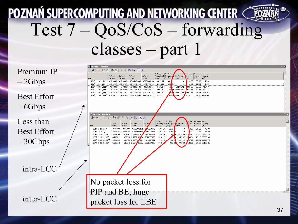
Test 7 – QoS/CoS – forwarding classes – part 1
Premium IP – 2Gbps
Best Effort – 6Gbps
Less than Best Effort – 30Gbps
No packet loss for PIP and BE, huge packet loss for LBE
intra-LCC
inter-LCC

38
Test 7 – QoS/CoS – forwarding classes – part 2
Premium IP – 2Gbps
Best Effort – 20Gbps
Less than Best Effort – 18Gbps
No packet loss for PIP, huge packet loss for BE, almost all traffic lost for LBE
intra-LCC
inter-LCC
39
Test 7 – QoS/CoS – forwarding classes – results
• PIP traffic has no packet loss
• BE has priority over LBE
• No ISIS adjacency or BGP session drop detected on congested links
CoS features behave according to service definition.
Results are the same for intra-LCC and inter-LCC traffic.

40
Test 7 – QoS/CoS – head of line blocking
Head of line blocking occures when traffic which should be transmitted via a congested interface blocks input queue on its ingress interface, which affects other on the same ingress interface – traffic which should not be congested

41
Test 7 – QoS/CoS – head of line blocking
Traffic:
• 203 to 101 – 100% of bandwidth
• 204 to 101 – 50% of bandwidth
• 204 to 102 – 50% of bandwidth
Link to 101 is congested
If TX has head of line blocking problem, the congestetion on 101 will affect traffic from 204 to 102
so-3
/0/0
STM
64
10.1
0.11
.0/3
0
so-3
/2/0
STM
64
10.1
0.21
.0/3
0
so-4
/0/0
STM
64
10.1
0.31
.0/3
0
so-4
/2/0
STM
64
10.1
0.41
.0/3
0
so-12 /0/0STM
64
10 .20.31.0/30

42
Test 7 – QoS/CoS – head of line blocking - results
Traffic from 204 to 102 was not affected.
No head of line blocking in this test scenario.No packet loss between 204 and 102

43
Many thanks to Jean-Marc Uzefor organising this testing.