June 11, 2010 Br¼ssel, Belgium The way to the full electric
35
Reiner John Infineon Technologies AG, Germany Ovidiu Vermesan SINTEF, Norway Marco Otella, Italy CRF Piedro Perlo, Italy CRF The way to the full electric vehicle (FEV) E3CAR June 11, 2010 Brüssel, Belgium Copyright 2010 Confidential Association for European NanoElectronics ActivitieS Green Car initiative
Transcript of June 11, 2010 Br¼ssel, Belgium The way to the full electric

Reiner John Infineon Technologies AG, GermanyOvidiu Vermesan SINTEF, NorwayMarco Otella, Italy CRFPiedro Perlo, Italy CRF
The way to the full electric vehicle (FEV)E3CAR
June 11, 2010 Brüssel, Belgium
Copyright 2010Confidential
Association for European NanoElectronics ActivitieS
Green Car initiative

Outline
The way to the full electric vehicle (EV)
! Objectives of the project and participating partners E3Car project in generalE3Car functional domains and research focus
! Major technological challenges and possible technological approach Component Efficiency based on Silicon technologiesSystem integration based on Modul- and Functional Integration (Powertrain, Safety, Energy sources)
! Exploitation potential Examples in the projectElectric vehicle outlook
! www.green-cars-initiative.eu/documents/Report_WS_EC-MS_Electric_Vehicle_R-D.pdf/view

Electrical and Hybrid Vehicles
Porsche Cayenne Hybrid SUVSource: Porsche/Audi
BluecarSource: Pininfarina/Bolloré
Tesla RoadsterSource: Tesla
Think CitySource: Think
Mila EV Source: Magna Steyr
i-MiEVSource: Mitsubishi
LeafSource: Nissan
PhyllaSource: Fiat
Renault Electric Concepts Source: Renault
Peugeot BB1 Source: Peugeot

Well to Wheel Conversion Efficiency
Efficiency of themal conversion processesis limited at 40 -45%
Coal Mine Utility Distribution Electrical Vehicle (EV)
97% 45% 93%
Charger
91% 97%
Transmission
85%
Battery
91%
Motor
Coal to electricity 40% 24%EV 60%
88%
PowerControlGrid
Engine (FUDS *) Transmission
Oil Well Refinery Distribution Combustion Engine Car
96% 90% 93% 28% 90%
Oil supply 80% Car 23% 18%Urban traffic* Highly efficient Diesel
*

Smart Power Electronics and Technologies enabling Regenerative Mobile Efficiency (RME)
100% x 60% = 60% Supply chain efficiency
Power plant
IGBT Module
Middle-voltageAC 30KV
LocalFar
IGBT, MOSFET, VHV CMOS, SiC, GaNIGBT, Modules
AC 220/380V Board netAC
ACAC
DC DC DCAC
DCAC AC AC
DC AC
Power plant
IGBT Module
High-voltageAC 380KV
LocalFar
Grid = Energy transfer E-Mobility
IGBT, Modules
Generator-voltage30KV
ACAC
ACDC DC DC
ACDC
AC AC ACDC AC
Charger
91% 97%
Transmission
85%
Battery
91%
Motor
88%
PowerControl93%100%
* Efficency is set to 100% because primary energy is not wasted

EV as Strategic Option in the Multi Billion $ Energy Household
http://rutledgecapital.com/2009/05/30/china-energy-mix/http://www.chinadaily.com.cn/bizchina/2009-08/10/content_8548057.htm
CHINA´s way to renewable energyCountries will choose mobility based on efficiency and cost
Oil supply (80%) ICE Car (23% eff. Diesel)x = 18%
Burn Coal (40%)
renewable (100%)
EV (60%)
EV (60%)
x
x
=
= 60%
24%
China Germany Norway Canada
weak automotive Industry
strong automotive Industry urban Non urban
80% life in 10% area
burning coal
EV 危機 EV, Diesel EV, DieselEV
renewable energy
機 + Replace Oil + Save Bill $ of coal by efficiency+ enable path to highly competitive automotive industry
Opt 1
Opt 2
Opt 3
High Emission
Low Emission
Zero Emission
China

Evolution and Phases of EV´s in Europe

Generations, needs and volume markets
Volume market cost
EV 1G
EV 2G
EV 3G
EV to GRID
EV to Cost
EV to Needs
> 40.000�
15.000�
20202015 2025
400KM 501KM TESLA
1000KM JPN

1899 >100kmh
1900 50kmWheel drive
1941 ~80km
1945 ~65km
MissingFossil oilresources
1971 92km
1991 250Km
1992 70km
1993
1996 220km
2008 300km
Evolution and Phases of EV´s:Market break troug after 100y?
2010 160km

Research in E-Mobility: Think big, Think different, Think holistic

Global competitors
Renewable Mobility: The global challenge

Team Blue
StandardizationChina practise since 3000yUS, J are one country
Standardization:Grid, Car, Tax, rules, Infrastructure, networking among thenational clusters and among the automotive manufacturerMobility needsPopulation: 500 MioDistance: 2000 kmEnergy basis: 25% Coal+25% NG
Mobility needsUS 300 Mio + China 1300 Mio + J 100 MioDistance: 4000 km
Advantages" US +C ->Non competitive Automotive
industry: J -> highly advanced AI" Standardization," Early Mass market
TeamRed
Europe and the Global competition

Mobility : Distance records 500KM
Leaders of the Eco class for production cars on the World Solar Challenge (now known as the Global Green Challenge) have set a new �world record� for distance traveled on one charge in a standard production Tesla Roadster of 501 kms or 313 miles. The car had about 3 miles of range left when the drive was completed.
Tesla Goes 313 Miles on Single Charge By Tony Borroz October 27, 2009 | 6:18 pm |Categories: EVs and Hybrids, PerformanceRead More http://www.wired.com/autopia/2009/10/tesla-313-miles/#ixzz0qLRDT5KI
501 km @ TESLAby Simon Hackett27.10.2009

Mobility : Distance records
One of the biggest problems that stands between electric vehicles and becoming mainstream is limitedbattery life. But there has been some progress in that area lately: the Japan Electric Vehicle Club [JP], a civic group based in Tokyo, announced today a Mira EV customized by the group traveled exactly1,003.184 kilometers without a recharge.The club shattered its own record from last month when another electric vehicle drove 555.6km (345 miles) from Tokyo to Osaka on a single charge. The new record was made possible by driving the car at a driving course in Shimotsuma, Japan, which is apparently the world�s longest.Powered by a Sanyo lithium-ion battery (built by assembling 8,320 cylindrical lithium-ion batteries), thecar ran for 27 and a half hours at around 40km/h on average.The club had a team of 17 people at the course who took turns at the wheel. It will ask the Guinness World Records to officially recognize the drive soon.
555.6 Km in Osaka1003 KM @ 40Km/h on MIRA EVby Japan Electric Vehicle Club 25.05.2010
Danielle Demetriou in Tokyo Published: 6:50PM BST 25 May 2010

Brühl, 18. Mai 2010 �Anschaffungskosten unter 30.000 Euro anbieten, worin Fördermittel oder Gutschriften eingerechnet sind. Vorreservierungen sollen ab Juli 2010 entgegengenommen werden.
Mobility : Cost records
Batterie: 48 Module laminierte Lithium-Ionen-BatterieKapazität: 24 kWh -> 160 Km -> 15KW/100kmLeistung: über 90 kW Energiedichte: 140 Wh/kg -> 171 Kg BatteryLeistungsdichte: 2.5 kW/kg Ladezeit: Schnelllader DC 50kW (0-80%): unter 30 Minuten AC200V Aufladung: unter 8 Stunden

Synergy of research programs and plattform in Europe for electro mobility
EV2.0
NanoelectronicsDevices
Components
MaterialsBatteries
ElectricalMotors
PassiveComponents
Embedded Systems
Architectures
LightingAircondition
Communication Systems
MechatronicSystems
Fully IntegratedPower train
EV2.0 EV2.0
EE33CarCar POLLUX
CASTOR
LIB2015

E3CAR Technology Platform Embedding
NationalClusters
E3Car POLLUX
FP7
CASTOR

ENIAC E3Car Project Vision:# Build a solid nanoelectronics technology base for Europe.# Establish standard designs and platforms for electrical/hybrid
vehicles with a significant industrial, economic, innovation and societal impact to enable the path to the all electrical vehicle.
# Development of efficient and smart semiconductor components for the first industrial generation of energy efficient electricalvehicles.

E3Car covers 3 EVs functional domains
Energy (Batteries, super capacitors, range extender, grid connection)
Propulsion (Power converters and motor-generators)
Auxiliary systems (Power supply only)
Power and signal distribution(Wiring, harnesses and intra vehicle communication)
Chassis (Steering, brake, suspensions and correlated functions)
Body and board control(HMI, vehicle entertainment, navigation,vehicle to vehicle (V2V and vehicle to infrastructure (V2I)
communication
E3Car

E3Car Project Targets

ENIAC E3Car Objectives / Key factsObjectives:Research and development of nanoelectronics technologies, devices, circuit architectures and modules to build efficient components for Electrical Vehicles (EVs) and demonstrations in the final systems.
Key facts:11 European countries involved22 Deliverables as Prototypes or Demonstrators 33 Project partners44 M� Budget -> 3500 PM
28 Design/Supply chains 36 Months duration

33 Project Partners cover the whole Value Chain
NederlandCzech
RepublicIrelandFinlandSpainFranceItalyNorwayBelgiumAustriaGermany
Germany
Austria
Italy France
France
Tier1 OEMSemiconductorResearch
WP Lead 1,6
WP Lead 2
WP Lead 4
WP Lead 3
WP Lead 7
WP Lead 8
Germany
AMS
Audi
FIATON SEMI
CNR
BRNO
WP Lead 5
Funded by EU and 11 national countries

E3CAR our Funding Partner

Major technological challenges and possible technological approach# Conversion of the drive train system$ modular and scalable electronic control systems$ intergrated and networking energy source in terms of
power dissimination and usage# Conversion of mobility and regenerative energy
- Offboard grid operation- Onboard energy harvesting (high efficient cells)
# Conversion of Urban traffic and mobility needs- Energy harvesting -> charging stations
! Mass market volume to drive the price
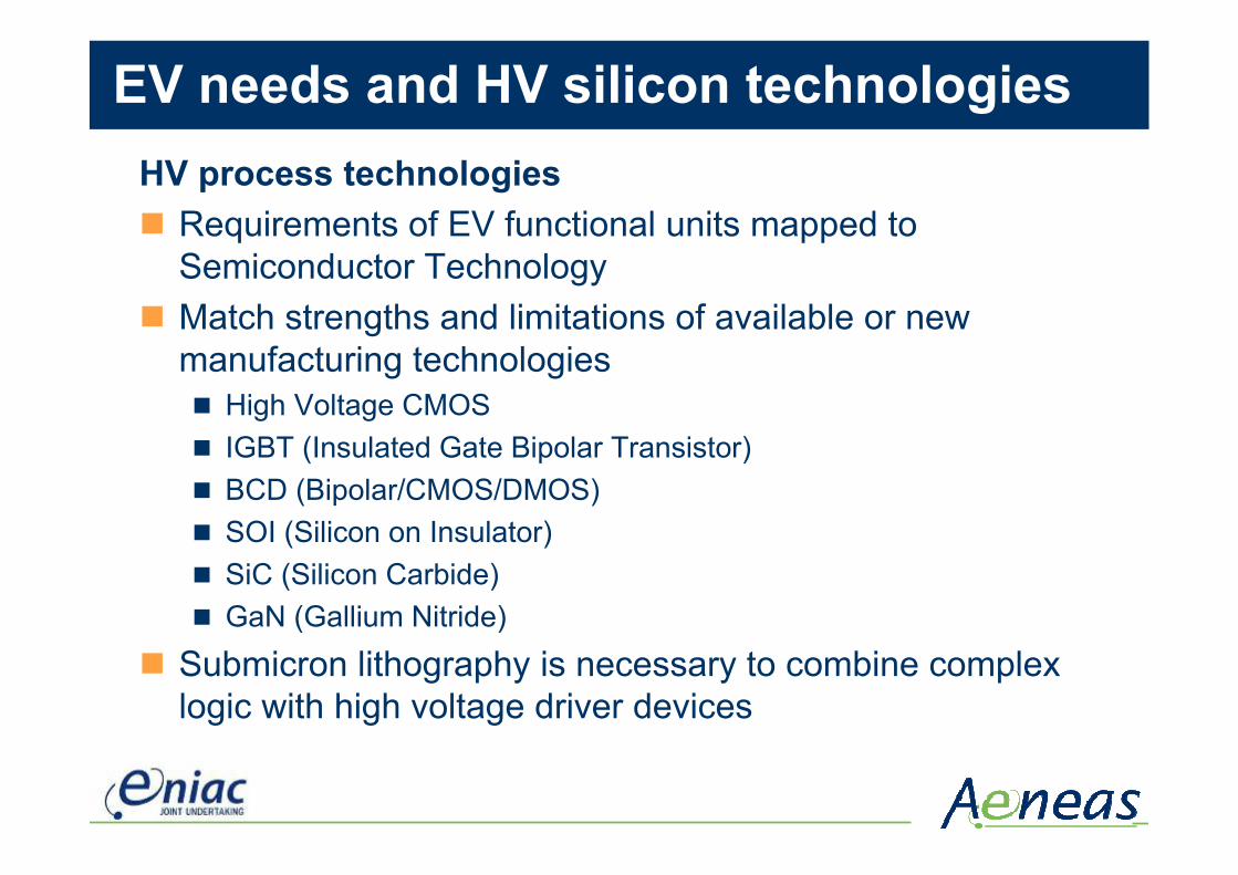
EV needs and HV silicon technologiesHV process technologies# Requirements of EV functional units mapped to
Semiconductor Technology# Match strengths and limitations of available or new
manufacturing technologies# High Voltage CMOS # IGBT (Insulated Gate Bipolar Transistor)# BCD (Bipolar/CMOS/DMOS)# SOI (Silicon on Insulator)# SiC (Silicon Carbide)# GaN (Gallium Nitride)
# Submicron lithography is necessary to combine complex logic with high voltage driver devices

Efficiency and Power technology
Structured in clusters of car classes based on rated power and DC-link voltage
Think
FiatClass A
Power Conversion -> +8% efficiency
Inverter Module

Power Management# Topologies - stack structures of Batteries (Li-Ion) or super
capacitors# Functional structures of battery management systems
translated in semiconductor technologies:# Addressing of battery cell# Monitoring of battery cell # Redundancy concepts for defect battery cells# Sizing of Battery cell balancing currents driving # Scalability of stack structures# Scalability of addressing structures to enabling redundancy# digital/analog and analog/digital conversion
# Potential:# HV CMOS Technologies will enable modular and scalable battery
managements system
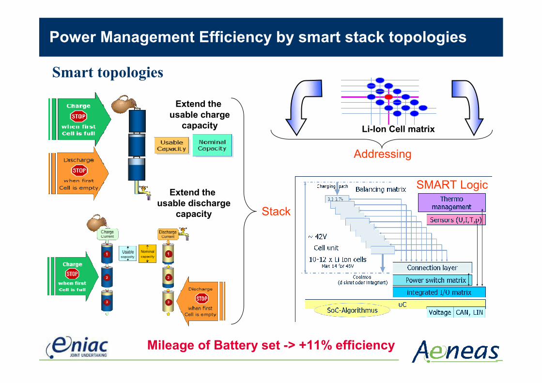
Mileage of Battery set -> +11% efficiency
Li-Ion Cell matrix
Extend the usable charge
capacity
Extend the usable discharge
capacity Stack
Addressing
SMART Logic
Power Management Efficiency by smart stack topologies
Smart topologies

Power Management - Solar Energy
Automotive photo voltaic panels for urban daily usage
Bypass-Diode
Current Source
Cell 1
Cell 2
Cell 3
Cell 4
Cell 3
Simple : Bypass
Multiphase DC/DC-converter with MPP-Control
Multiphase DC/DC-converter with MPP-Control
Multiphase DC/DC-converter with MPP-Control
Multiphase DC/DC-converter with MPP-Control
SMART: Impedance conversion
Cell mismatch as a result of divergent angles of incidence:
Stack
SMART Logic

! Development of a near-series starter accumulator (Li-Ion)! Operation strategies for complete system! Optimization of %
$ Conductor rails (weight - form - heat build-up)$ SOC/SOH algorithms$ Strategies for charging and
charge balance$ Thermo management$ µElectronic devices, sensors
and power electronic$ Communication between accumulator
and automobile
Demonstrator 12 V Starter Accumulator
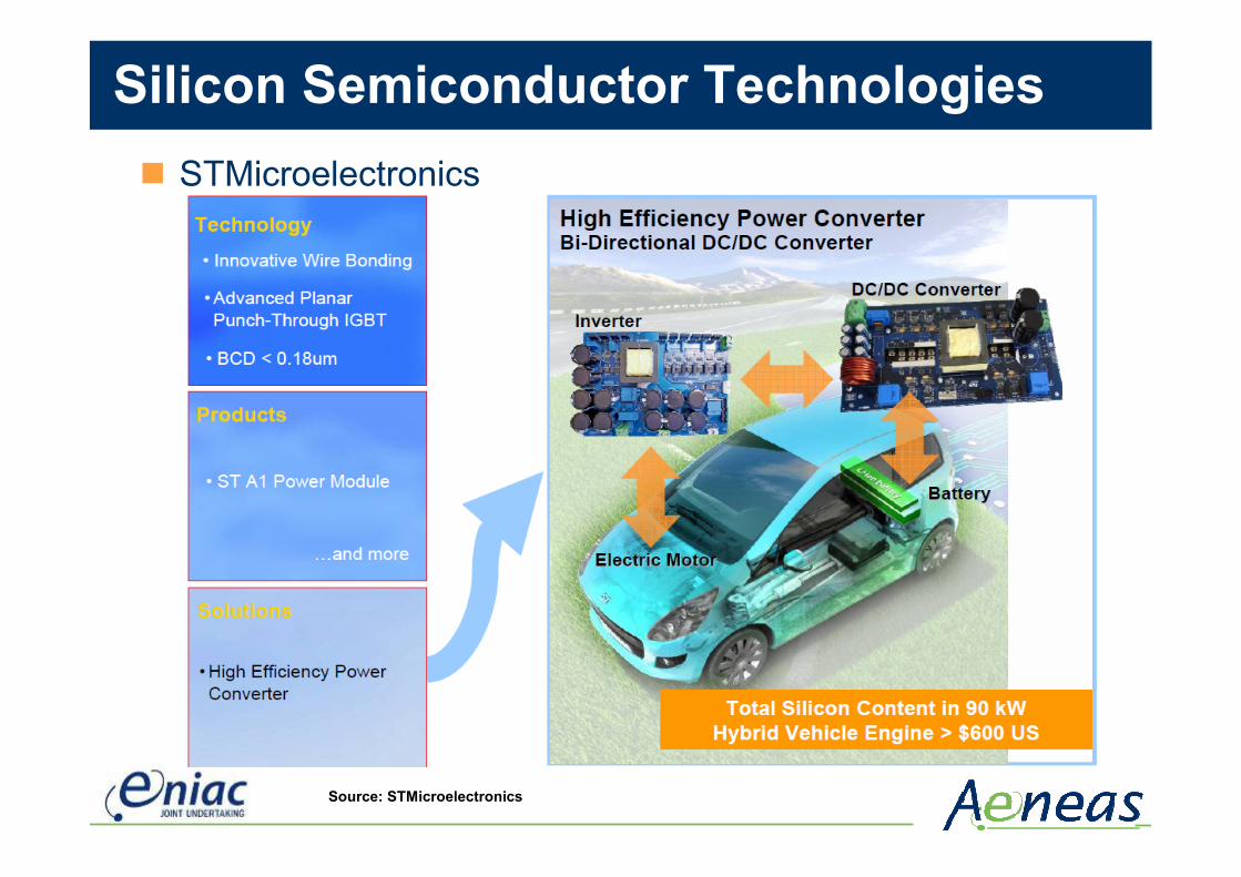
Silicon Semiconductor Technologies# STMicroelectronics
Source: STMicroelectronics

#Fully dielectric isolation#A high-performance 0.15 µm CMOS process with embedded options for automotive, aerospace and power management SoC (System-on-Chip) applications#Less parasitics for robust design and high EMI performance#Very low leakage current even at high temperatures#Latch-up-free operation over complete temperature range#TJunction=175°C
BCD-on-SOI Technology
(through 1st metal layer)
Drain DrainSource/Bulk Source/Bulk Collector Base Emitter Collector Base Emitter5V PMOS 5V NMOS LNPN LPNP
Pol y
Drain DrainSource/Bulk Source/Bulk
P-LDMOS N-LDMOS Zener-Diode EEPROMSource/Bulk node CathodeDrainDrain Source/Bulk Bit line
SiO2Si-Handle
N-Well P-Well
SiO2Si-Handle
N-WellP-Well
NFDP+
VT2
Poly-SiBPSG
NLDD
N+
Poly-Si
N-DRIFT N-Ext BUR-N
TunnelOxide
P+ N+BPSG
PFD
Source: Atmel

CMOS High Voltage Process
# 120V n-channel LDMOSFET: Potential distribution at 160V
# 0.35 µm technology# 120V n-channel LDMOS Lateral
Diffused MOS transistor# Thick Gox (Vgmax=20V)# Blocking voltage over 150 V# Low HC degradation# Low Ron by non-uniform NWELL
Source: austriamicrosystems

Reliability# Solder replaced at terminal joints- direct copper bonded# Roll out of direct copper bonded terminals
# TST (-40 / +150) up to 1000 Cycles tested
PIN-FIN base plate for direct water cooling
Source: Infineon
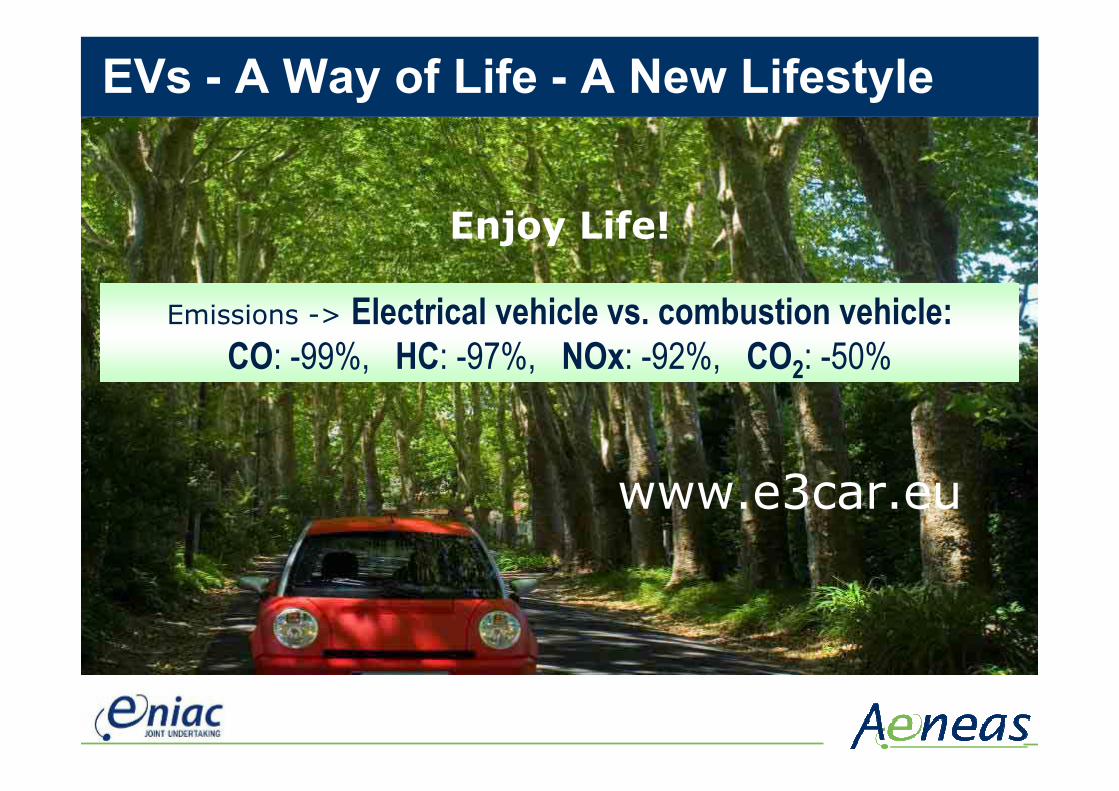
EVs - A Way of Life - A New Lifestyle
Enjoy Life!
Emissions -> Electrical vehicle vs. combustion vehicle:CO: -99%, HC: -97%, NOx: -92%, CO2: -50%
www.e3car.eu