Juliana Fabricio Freire Thunderbolt over Type-C · PDF fileThunderbolt over Type-C Overcoming...
63
Thunderbolt over Type-C Overcoming Test Challenges Juliana Fabricio Freire Keysight Technologies Engenheira de Aplicações [email protected] June, 2016
Transcript of Juliana Fabricio Freire Thunderbolt over Type-C · PDF fileThunderbolt over Type-C Overcoming...

Thunderbolt over Type-C Overcoming Test Challenges
Juliana Fabricio Freire
Keysight Technologies
Engenheira de Aplicações
June, 2016

Page
Agenda
– Thunderbolt 3 Overview
– Measurement Challenges
– Tx Testing Solution
– Return Loss Testing
– Power Delivery Testing
– Rx Testing Solution
– Summary
Thunderbolt over Type-C -
Overcoming Test
Challenges 2

Page
What is Thunderbolt?
– Thunderbolt features two bidirectional (full duplex) channels that run up to
20Gbps each and allows daisy-chaining of up to six devices.
– Passive or active Cable
– Thunderbolt tunnels two protocols (PCI Express and DisplayPort) when
running in native Thunderbolt mode.
3
Thunderbolt over Type-C -
Overcoming Test
Challenges

Page
Evolution of Thunderbolt
Thunderbolt over Type-C -
Overcoming Test
Challenges 4
Thunderbolt 3
4-lane 20 Gbps
1ch 40Gbps 2015
Thunderbolt 2
4-lane 10 Gbps
1ch 20Gbps 2013
Thunderbolt 1
4-lane 10 Gbps
2ch 10Gbps 2011

Page
Thunderbolt 3 Overview
– Announced in Q2 2015
– Uses the Type-C connector
– Channel aggregation: two independent 20Gbps links into one logical 40Gbps link
– Supports other standards through ALT mode
– Cost competitive vs multi-chip, discrete, mux solutions
Thunderbolt over Type-C -
Overcoming Test
Challenges 5

Page
More Speed
– 40Gb/s Thunderbolt™ 3
• Bi-directional, PCI Express and DisplayPort
• Four lanes of PCI Express Gen 3
• Eight lanes of DisplayPort 1.2
– Native USB 3.1 (up to 10Gb/s)
– Native DisplayPort 1.2
Thunderbolt over Type-C -
Overcoming Test
Challenges 6

Page
More Possibilities
Thunderbolt over Type-C -
Overcoming Test
Challenges 7

Page
Configurations
– Daisy-chain up to six devices if the link is in Thunderbolt mode
– Second device port operates the same as computer port and supports Thunderbolt, USB,
and DisplayPort devices
Thunderbolt over Type-C -
Overcoming Test
Challenges 8

Page
Agenda
– Thunderbolt 3 Overview
– Measurement Challenges
– Tx Testing Solution
– Return Loss Testing
– Rx Testing Solution
– Power Delivery Testing
– Summary
Thunderbolt over Type-C -
Overcoming Test
Challenges 9

Page
Testing Methodology
– PHY testing approach will be similar to Thunderbolt 2
- Tx, Rx, and Return Loss
- PD for Type-C Alternate Mode
- DP, USB for Type-C
– Keysight can help with pre-compliance testing
Thunderbolt over Type-C -
Overcoming Test
Challenges 10

Page
Measurement Challenges
Thunderbolt over Type-C -
Overcoming Test
Challenges 11

Page
Measurement Challenges
How do I
ensure the
transmitter is
in spec?I
Thunderbolt over Type-C -
Overcoming Test
Challenges 12

Page
Measurement Challenges
How do I
ensure the
transmitter is
in spec?I
Is my receiver
capable to
dectect signal
reliably at
40Gb/s?I
Thunderbolt over Type-C -
Overcoming Test
Challenges 13

Page
Measurement Challenges
How do I
ensure the
transmitter is
in spec?I
Do I need to
purchase Test
Equipment for
Thunderbolt, USB
and DisplayPort?I
Is my receiver
capable to
dectect signal
reliably at
40Gb/s?I
Thunderbolt over Type-C -
Overcoming Test
Challenges 14

Page
Type-C Design and Test Challenges: Overview
Receiver Test
USB 3.1
USB 2.0
Alternate modes
Power Delivery
Transmitter Test
USB 3.1
USB 2.0
Alternate modes
Power Delivery
Interconnect Test
TxTx
RxCable
15
Thunderbolt over Type-C -
Overcoming Test
Challenges

Page
USB 3.1 TX Compliance Application
Thunderbolt over Type-C -
Overcoming Test
Challenges 16
Keysight solution features:
Support USB3.1 Gen1/Gen2
USB-IF Sigtest & Keysight SDA
algorithm
CTLE Adc scan
Support live & saved
waveforms
USB-IF and customer’s
embedded transfer function
External instrument for
triggering SCD1/2, LBPM and
toggle Compliance Pattern

Page
Simulation-Measurement Correlation Challenge
Type-C Revolution
Simulation…
17
Bridging script generates reportDesign and simulate
Prototype in lab
≠Physical Measurements…
Scope compliance application

Page
Simulation Test Solutions: Advanced Design System
18Type-C Revolution
Page
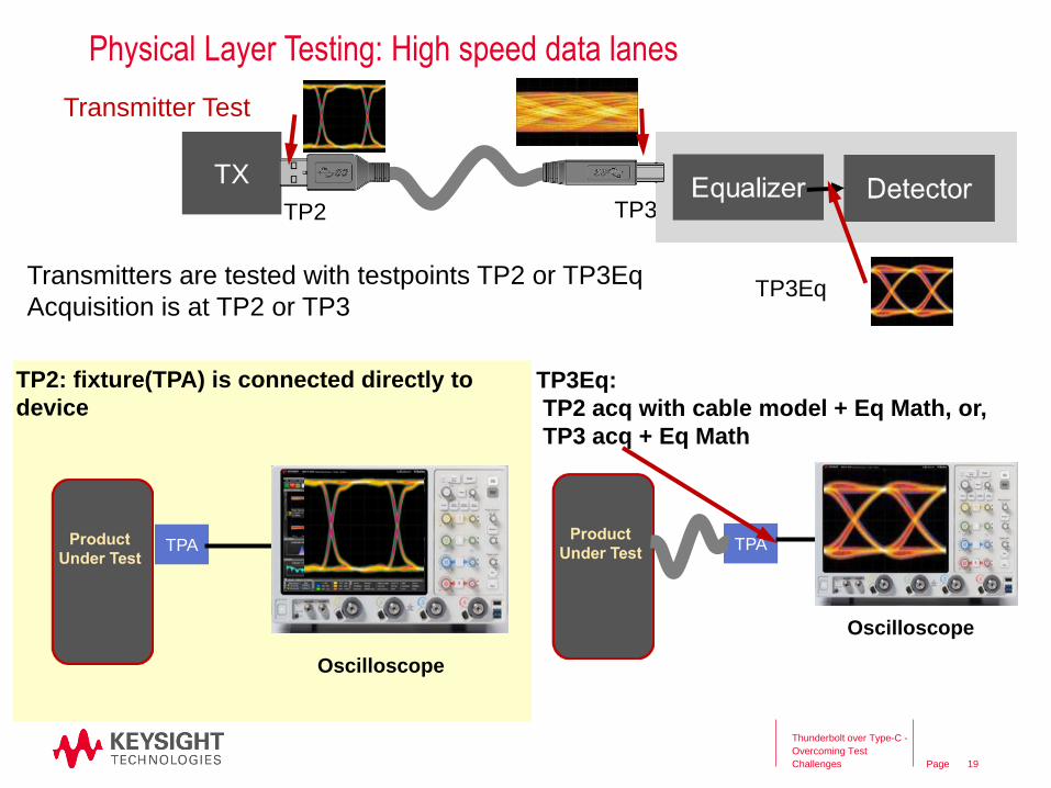
Physical Layer Testing: High speed data lanes
Thunderbolt over Type-C -
Overcoming Test
Challenges 19
Transmitter Test
TP2: fixture(TPA) is connected directly to
device
Transmitters are tested with testpoints TP2 or TP3Eq
Acquisition is at TP2 or TP3
TP3
TP3Eq
TP2
TPA
Oscilloscope
TPA
TP3Eq:
TP2 acq with cable model + Eq Math, or,
TP3 acq + Eq Math
Oscilloscope
TX

Page
Physical Layer Testing: High speed data lanes
Thunderbolt over Type-C -
Overcoming Test
Challenges
Transmitter Testpoints
20
Standard TP2 TP3 TP3Eq Comments
USB3.1compliance
USB3.1 pre-comp x
x Y
Y
USB3.1 has various fixtures
One connection testing.
Test Mode signal compliance patterns
TBT3 x PRBS31 is effectively random data signal.
DP1.4 x Y D10.2, PRBS7, HBR2CPAT
MHL3.3 x Y BIST randomized PRBS
Each Standard has its own suite of tests each with their own particular
measurement processes.
Acquisition
Page
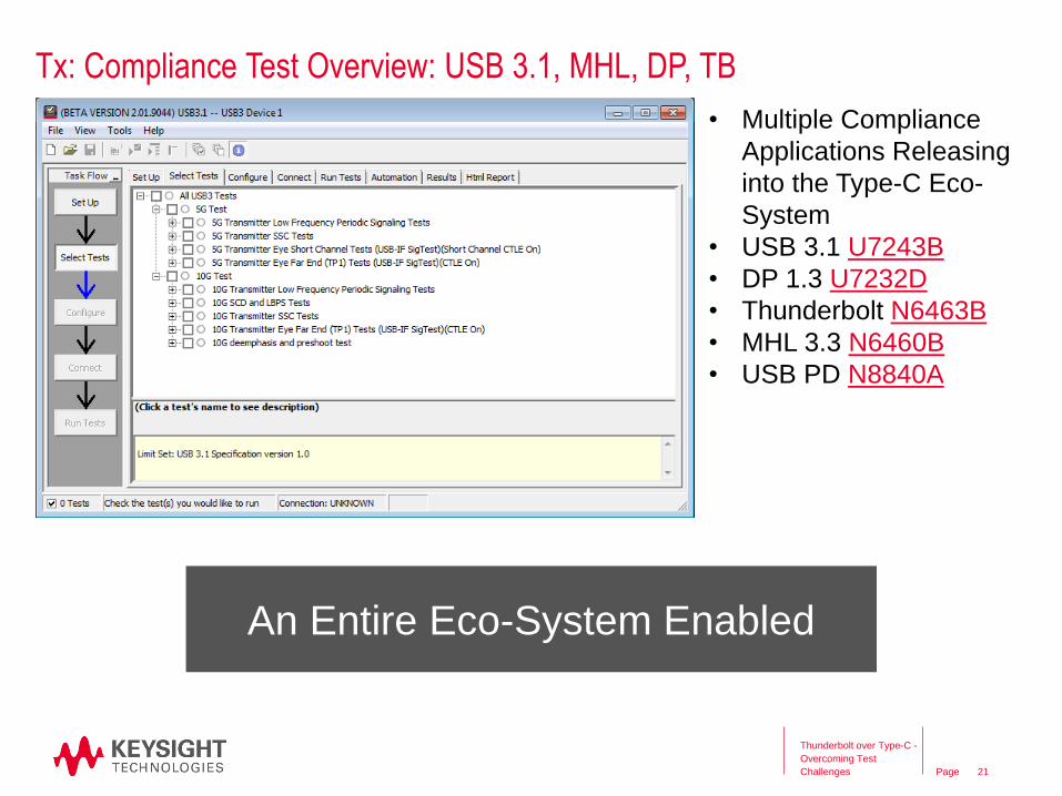
Tx: Compliance Test Overview: USB 3.1, MHL, DP, TB
Thunderbolt over Type-C -
Overcoming Test
Challenges 21
• Multiple Compliance
Applications Releasing
into the Type-C Eco-
System
• USB 3.1 U7243B
• DP 1.3 U7232D
• Thunderbolt N6463B
• MHL 3.3 N6460B
• USB PD N8840A
An Entire Eco-System Enabled

Page
• Highest signal integrity Type-C test fixture
• Type-C plug interface fixture handling
connector “flip”
• Compliance test capability for USB 3.1,
DisplayPort 1.3, Thunderbolt 2/3, MHL
• Best signal integrity: 20 GHz bandwidth
(at -3 dB), de-embeddable up to 30 GHz
• Provides test point and probing access
for transmitter and power delivery
measurements
• Provides the elements to seamlessly
leverage Keysight’s portfolio of compliance
test applications
Tx: Compliance Test Overview: New High Speed Fixture
Thunderbolt over Type-C -
Overcoming Test
Challenges 22

Page
Tx: Special Decoders and Triggers for the Type-C Ecosystem
23
Thunderbolt over Type-C -
Overcoming Test
Challenges
USB Power Delivery Decode
• Industry’s only hardware based triggering
• Time aligned decoding
• Set up the entire trigger in 30 seconds
• Quickly scan through numerous events
USB 3.1 Decode
• Industry’s only USB 3.1 decoder
• Time aligned decoding
• Quickly scan through numerous events
Page
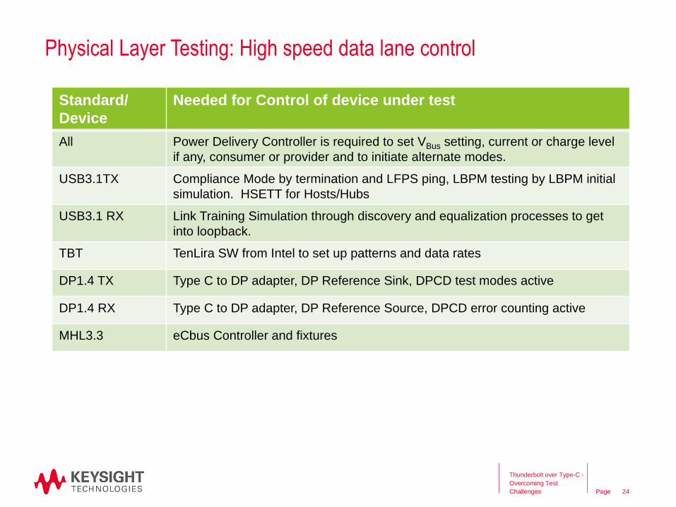
Physical Layer Testing: High speed data lane control
Thunderbolt over Type-C -
Overcoming Test
Challenges 24
Standard/
Device
Needed for Control of device under test
All Power Delivery Controller is required to set VBus setting, current or charge level
if any, consumer or provider and to initiate alternate modes.
USB3.1TX Compliance Mode by termination and LFPS ping, LBPM testing by LBPM initial
simulation. HSETT for Hosts/Hubs
USB3.1 RX Link Training Simulation through discovery and equalization processes to get
into loopback.
TBT TenLira SW from Intel to set up patterns and data rates
DP1.4 TX Type C to DP adapter, DP Reference Sink, DPCD test modes active
DP1.4 RX Type C to DP adapter, DP Reference Source, DPCD error counting active
MHL3.3 eCbus Controller and fixtures
Page
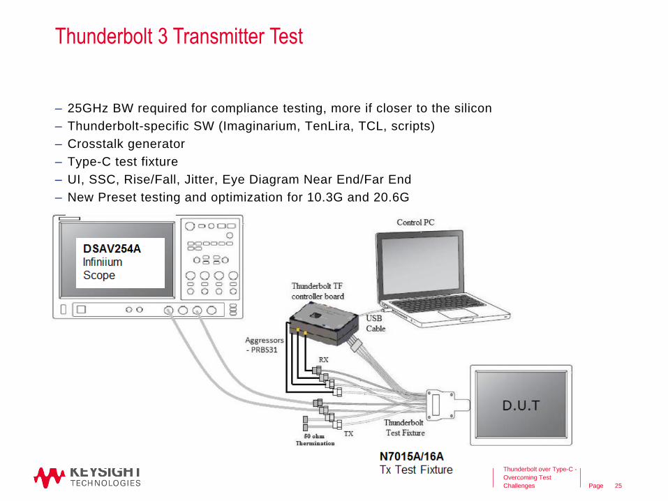
Thunderbolt 3 Transmitter Test
– 25GHz BW required for compliance testing, more if closer to the silicon
– Thunderbolt-specific SW (Imaginarium, TenLira, TCL, scripts)
– Crosstalk generator
– Type-C test fixture
– UI, SSC, Rise/Fall, Jitter, Eye Diagram Near End/Far End
– New Preset testing and optimization for 10.3G and 20.6G
Thunderbolt over Type-C -
Overcoming Test
Challenges 25
Page
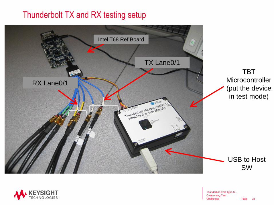
Thunderbolt TX and RX testing setup
TBT
Microcontroller
(put the device
in test mode)
USB to Host
SW
TX Lane0/1
RX Lane0/1
Intel T68 Ref Board
Thunderbolt over Type-C -
Overcoming Test
Challenges 26

Page
Type-C Design and Test Challenges: Overview
Receiver Test
USB 3.1
USB 2.0
Alternate modes
Power Delivery
Transmitter Test
USB 3.1
USB 2.0
Alternate modes
Power Delivery
Interconnect Test
TxTx
RxCable
27
Thunderbolt over Type-C -
Overcoming Test
Challenges

Page
Type-CTM Cable/Connector Challenges
28
• Significant loss at higher frequencies require more rigorous approach to removing
fixture effects, to measure the true performance of the device
• Channel response affected by many features in channel (loss, reflection,
crosstalk, mode conversion)
• Managing EMI and RFI levels from the cable assembly
Thunderbolt over Type-C -
Overcoming Test
Challenges

Page
Type-CTM Cable/Connector Challenges
• Significant loss at higher frequencies require
more rigorous approach to removing fixture
effects
2x thru de-embedding, or TRL calibration
29
ENA-TDR Enhanced Time Domain Analysis Option with ECal
Module (N4433A)
• Channel response affected by many features
in channel (loss, reflection, crosstalk, mode
conversion)
Paradigm shift from traditional parametric
testing to stressed eye testing (Channel
Metrics/Margin)
• Managing EMI and RFI levels from the cable
assembly
Cable Shielding Effectiveness
Thunderbolt over Type-C -
Overcoming Test
Challenges

Page
Thunderbolt over Type-C -
Overcoming Test
Challenges 30
Test Fixtures
Fixtures are available for purchase
through Luxshare-ICT.
http://web.luxshare-ict.com/en/MOI(Method of
Implementation)
Step-by-step procedure on
how to measure the
specified parameters in the
specification document
using ENA Option TDR.
•ENA Mainframe
•E5071C-4D5: 4-port, 300 kHz to 14 GHz
•E5071C-4K5: 4-port, 300 kHz to 20 GHz
•Enhanced Time Domain Analysis Option (E5071C-TDR)
•ECal Module (N4433A)
(*) The list above includes the major equipment required. Please contact our local sales
representative for configuration details.
•Method of Implementation (MOI)
document and instrument setup file
will be made available for download
on Keysight.com
ENA Option TDR is a authorized test tool for Cable PHY.
http://www.vesa.org/displayport-developer/certified-components/
Type-CTM Cable/Connector Challenges

Page
– DUT output PRBS31 on all lanes with SSC turned on
– Setup the Network Analyzer with automated measurements specific to
Thunderbolt 3
Thunderbolt over Type-C -
Overcoming Test
Challenges 31
Type-CTM Cable/Connector Challenges

Page
Type-C Design and Test Challenges: Overview
Receiver Test
USB 3.1
USB 2.0
Alternate modes
Power Delivery
Transmitter Test
USB 3.1
USB 2.0
Alternate modes
Power Delivery
Interconnect Test
TxTx
RxCable
32
Thunderbolt over Type-C -
Overcoming Test
Challenges

Page
Receiver Testing: High speed data lanes
Thunderbolt over Type-C -
Overcoming Test
Challenges
Review: Link Budget
33
Minimum and maximum amplitude
TX Pre-Emphasis/Equalization
TX Jitter
Amplitude noise
Transition time/BW
Minimum Amplitude
RX Equalization
Jitter tolerance
Crosstalk
BER Out
RX: Minimum Eye In (the impaired eye)
Channel: a cable with a
worst case loss characteristic
TX: Minimum Signal Fidelity
Receiver Detector
A link with:
-a transmitter with minimum signal fidelity performance with,
-a cable that exhibits worst case characteristic (or better) and,
-a receiver that passes minimum eye requirement,
-> is guaranteed to work!
TX RX

Page
Receiver Testing: High speed data lanes
Thunderbolt over Type-C -
Overcoming Test
Challenges 34
Receiver Model
Equalizer DetectorData OutSignal In
TPnTPnEq
0 1 0 0 0 1 0 1 1 …
CTLE
Continuous
Time Linear
Equalizer
DFE
Decision
Feedback
Equalizer
The CTLE and
the DFE are
mathematically
implemented
on an
oscilloscope
TPn
TPn TPnEq
TPnEq

Page
Receiver Testing: High speed data lanes
Thunderbolt over Type-C -
Overcoming Test
Challenges 35
TPA TPA
Calibration: acquisition and mathematical processing for Equalization and Eye
measurement to meet impaired eye requirement.
Mating C fixtures
BER testing by:
-Loop back and BERT measurement.
-DUT Internal mode reporting BER
Adjustable Pattern
GeneratorOscilloscope
High Quality Coax
Adjustable Pattern
Generator
BER Analysis
Test: Apply impaired signal, measure BER
TPA
ISI
(i.e. Cable)
JBERT
ISI
(i.e. Cable)

Page
Receiver Testing: High speed data lanes
Thunderbolt over Type-C -
Overcoming Test
Challenges 36
Standard CTLE DFE BER Method Comments
USB3.1 x x Loopback Requires sophisticated protocol aware pattern
generator to go through the link training process
TBT3 Internal PRBS31
DP1.4 x x Internal HBR2CPAT (2520 bit pattern)
MHL3.3 x Internal BIST randomized PRBS
Each Standard has its own ‘cocktail’
of jitter components and level
settings to create the impaired eye.
These components of jitter are
measured by oscilloscope during
calibration process. Impaired
eyeM8020A JBERT

Page
Thunderbolt - Jitter Impairment Calibration for RX testing
Host / Device 10G & 20G
Inner eye Voltage
Random Jitter
Periodic Jitter Total Jitter
Test Case (mV peak) (UI pp) (UI pp) (UI pp)
1 350 0.14 0.17 0.38
2 35 0.14 0.17 0.66
Note:
1. The device should be tested by injecting several different periodic jitter
components, one at a time. The test should include at least the
following sinusoidal jitter frequencies: 1MHz, 2 MHz, 10 MHz, 50MHz, and 100MHz.
2. AC common-mode noise should be added at the pattern-generator for
ensuring worst-case transmitter characteristics. The total common-
mode noise should be 100mV peak-to-peak, where the added noise profile shall be sine-wave at frequency not smaller than 400MHz.
Thunderbolt over Type-C -
Overcoming Test
Challenges 37

Page
Test Case 2
Passive Cable
Test Case 1
Active Cable
Thunderbolt – Test Cases and Calibration Points
Thunderbolt over Type-C -
Overcoming Test
Challenges 38

Page
Receiver Testing: USB RX Test-Loopback
Thunderbolt over Type-C -
Overcoming Test
Challenges 40
Power-
up
Rx.
Detect.
Reset
Rx.
Detect.
Active
Polling.
LFPS
Polling.
RxEQ
Polling.
Active
Polling.
Config-
uration
Polling.
Idle
Polling.
Config-
uration
Polling.
Idle
Loop-
back
Loop-
back
warm
reset
warm reset
de-assert
termination
detected
SCD1 LFPS
handshake
TSEQ
transmitted
TS1
received
TS2
receivedif directed
multiple states
Comp-
liance
Rx.
Detect.
Reset
Rx.
Detect.
Active
Polling.
LFPS
Polling.
RxEQ
Polling.
Active
Power-
up
Polling.
LFPS
Plus
SCD2 LFPS
handshake
Polling.
LFPS
Plus
Polling.
Port-
match
PHY
Capability
LBPM
handshake
Polling.
Port-
match
Polling.
Port
Config
PHY
Ready
LBPM
handshake
Polling.
Port
Config
The DUT must brought through the whole link training state machine in order to get to
the loopback state.

Page
Receiver Testing: USB3.1 Loopback Training tool
Thunderbolt over Type-C -
Overcoming Test
Challenges 41
M8020A JBERT
• USB Link Training Suite is
a trainings sequence
generation tool for USB3.1
Gen1/2
• Easy manipulation of
• SCD1/SCD2/LBPM
cycles
• TSEQ count
• TS1 count
• TS2 count
• LFPS parameters
adjustment:
• tPeriod, tBurst,
tRepeat, tPWM….
• Choice of:
• Power On sequence
• Warm Reset sequence

Page
Thunderbolt System and testpoints
Thunderbolt over Type-C -
Overcoming Test
Challenges 42
TBT
ASIC
m
DP
m
DP
TBT
ASIC
test board
test board
active cable
test
board
test
boardTx Eye
Mask
Test controller boards and text
fixtures are developed by Wilder
Technologies,
can be procured through Agilent
Rx Eye
Mask
The active cable provides a very robust channel which doesn’t need any
kind of link training (unlike PCIe 3 for example). Therefore Rx and Tx
physical layer compliance test is rather simple and straight forward.

Page
Agenda
– Thunderbolt 3 Overview
– Measurement Challenges
– Tx Testing Solution
– Return Loss Testing
– Power Delivery Testing
– Rx Testing Solution
– Summary
Thunderbolt over Type-C -
Overcoming Test
Challenges 43

Page
N7016A Type-C low speed signal access and control fixture
Thunderbolt over Type-C -
Overcoming Test
Challenges
•Access to CC1, CC2, SBU1, SBU2, VBUS and
GND
•Controls to terminate CC1, CC2
independently (RA, RP, RD)
•Control to load VCONN
•External power for power consumers
•Type C receptacle to plug into other devices
or cables (Port 2)
•USB2.0 interface for external control from
application or standalone SW on a PC
44

Page
N8837A USB-PD Protocol Trigger and Decode
Thunderbolt over Type-C -
Overcoming Test
Challenges 45
• Support for the USB-PD CC 4b/5b
BMC encoded protocol.
• On-screen serial decode
synchronized with the serial
waveform
• 4b, 5b or Label display formats
• Unique listing-window view of data
transfer information with an
automatic click and zoom and
column sort.
• Serial packet search with navigation
controls
• Software trigger on search for orders
Sets, Control Packets, Data Packets,
and Errors.

Page
Power Delivery: Physical Layer Compliance Test
• Keysight Infiniium S-Series Oscilloscope
o N2873A Standard Passive Probes for CC and
VBUS
• 1147B Current Probe for Load Current
• GRL-USB-PD Power Delivery SW
• USB-PD Coupon(s) from Wilder-Tech or Luxshare-
ICT (USB3.1-C-PDC or TF21-215G USB-PD
Coupon)
• GRL-USB-PD-C1 Controller
• Keysight Power Supply and Load
http://literature.cdn.keysight.com/litweb/pdf/5992-1463EN.pdf

Page
Power Delivery: Physical Layer Compliance TestChapter 5

Page
• Chapter 7: Power Supply
- Depending on Power Profile 1-5
- Source or Load Requirements
- Considering explicit Watts and Voltage
Power Delivery: Power Supply Profile TestChapter 7

Page
Power Solutions for Type-C PDChoose from these instruments that meet the requirements
– Sourcing and Loading
N6752A high performance DC source module and N3303A DC electronic load module meet stringent
combination of requirements for slew rate, transient response and power demands of USB PD 2.0
validation testing
– Most ordinary power products do not meet the necessary combination of requirements
N3301A System DC Electronic
Load with N3303A load module
Load: 240V, 10A, 250W
N3303A
N6705B DC Power Analyzer or N6700 Modular
Power System with N6752A DC power module
Source: 50V, 10A, 100W
N6705B
N6752A
N6700 series N3301A

Page
USB-PD Power Integrity Measurements
50
• Supply drift
• PARD (Periodic and Random
Disturbances)—noise, ripple and
switching transients on power
rails.
• Static and dynamic load
response.
• Programmable power rail
response.
• High frequency transients and
noise.
• Product electrical validation at
extended temperatures.

Page
Large DC Offset—Probe Offset or DC Block
51
DC Block
Using a DC Block(misses DC and low frequency content)
Using Probe Offset
USB 5V supply
USB 5V supply

Page
N7020A Power Rail Probe
52
Characteristics and Specifications: N7020A Power Rail Probe
Probe Bandwidth (-3dB) 2GHz
Attenuation Ratio 1:1
Offset Range ± 24V
* Input Impedance @ DC 50kΩ +/-2%
Active Signal Range ± 850mV about offset voltage
Probe Noise 10% increase to the noise of the connected oscilloscope
Probe Type Single-ended
Included accessoriesN7021A—Coaxial Probe Head (qty 3) ($175 us)
N7022A –Main Cable ($240)
Maximum non-destructive input voltage +/-30V (DC + peak AC)
Output impedance 50Ω
Cable length N7021A Main Cable: 48”
N7022A Coaxial Probe Head: 8”
Ambient operating temperature Probe Pod: 0 – 40°C,
N7021A main cable, N7022A coaxial probe head: 0 – 85° C
Page
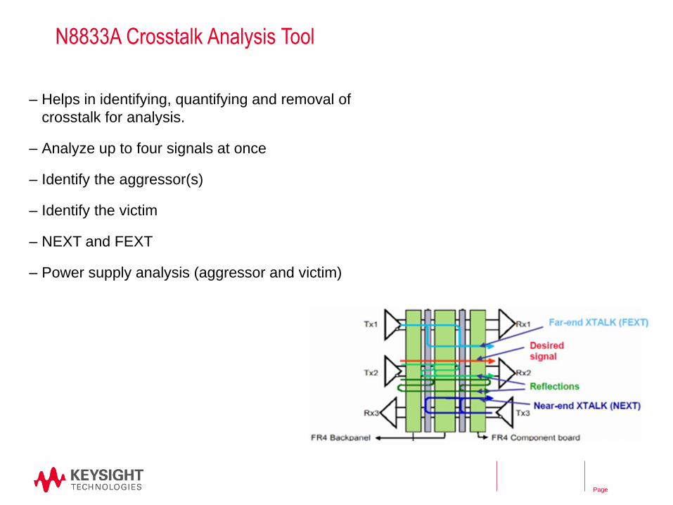
N8833A Crosstalk Analysis Tool
– Helps in identifying, quantifying and removal of
crosstalk for analysis.
– Analyze up to four signals at once
– Identify the aggressor(s)
– Identify the victim
– NEXT and FEXT
– Power supply analysis (aggressor and victim)

Page
USB-PD Test Solutions Overview
– N7020A PD Probe
– N7016A PD Test Fixture
– N8837A PD Decode SW
– N8833A Crosstalk Analysis SW
– Portfolio of Power Sources and Loads
– GRL USB-PD PHY Compliance Solution

Page
Example Device
Your Type C device is USB3.1 Gen2 enabled and has a DP TX alt mode (4
lane) and will be a power provider at 18W profile
You will need to address:
Thunderbolt over Type-C -
Overcoming Test
Challenges 55
Standard Protocol Phy Layer
USBPD2 X X (PD Comm on cc1 and cc2, I and V
for Vbus)
USB2.0 X X (RX & TX)
USB3.1 X X (HSD: RX & TX)
DP1.4 X X (HSD: TX)/AUX Channel
Focus on the New

Page
Example Device: Getting Started
First step…..Signal Observation, Access and Control.
– Consider test fixtures N7015A, N7016 and the flexibility they bring.
– Phase matched cables. Adapters etc.
– Acquire various link partners
Thunderbolt over Type-C -
Overcoming Test
Challenges 56
N7015A USB Type C
High Speed Fixture
N7016A USB Type C
Low Speed Fixture
TXRX Ports
USB2
SBUs
CC1/2 VBus

Page
Example Device: Power Delivery
Thunderbolt over Type-C -
Overcoming Test
Challenges 57
PDC
Voltage probe Current probe
S series Oscilloscope
Power Delivery
Compliance SoftwareTest coupon
Power Supply/Load

Page
Example Device: USB3.1 RX
Thunderbolt over Type-C -
Overcoming Test
Challenges 58
Mating
Fixture
Port 1
Port 2
Calibration Setup
Port 1
Port 2
Test Setup
RXTX
RXTXRXTX
PDC
ISI
ISI
CLE1000
CLE1000
V series Oscilloscope
RXTX
Plug Fixture
Power Supply/Load
Plug Fixture
Signal Access and
Control Fixture
Page
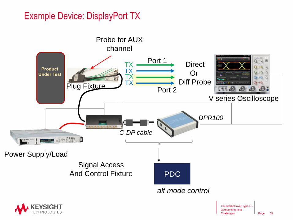
Example Device: DisplayPort TX
Thunderbolt over Type-C -
Overcoming Test
Challenges 59
Port 1
Port 2
TXTXTXTX
PDC
Direct
Or
Diff Probe
DPR100
C-DP cable
alt mode control
V series Oscilloscope
Probe for AUX
channel
Plug Fixture
Power Supply/Load
Signal Access
And Control Fixture

Page
Source Test Solution
V-Series Infiniium
Oscilloscopes
U7232D DisplayPort
Compliance Test SW
Computer Motherboards,
ICs, Graphic Cards
Media Testing
E5071C ENA
Cables, PC Boards,
Connectors
Sink Test Solution
M8020A JBERT
Wilder TPA
PC Monitors
N5990A Rx
Compliance
Test SW
Link Layer
& General
Solutions
N4915A-006
DP ISI GenerationUnigraf DPR-100
For automation
Protocol Debug solution
Granite River Labs
GRL-DP-DEC
Unigraf DPT-200
for Automation
Main Link
Analysis
16900A w/FS4430
From FuturePlus
BIT-DP-RTF-0002
BIT-DP-CBL-0002
Artek CLE1000
N7015A TPA
Luxshare Rec
STD/mDP USB C
Luxshare Rec
STD/mDP USB CSTD/mDPUSB C
Wilder TPA N7015A TPA
Keysight DisplayPort1.3 Solutions
Thunderbolt over
Type-C -
Overcoming Test
Challenges 60

Page
Thunderbolt 3 – Total Solution
Transmitter Test Receiver Test
SW
HW
Fixture
DUT Tx
V-Series Infiniium
Oscilloscope
RxError
counter
Thunderbolt
Transmitter Test
Software
N5990A Automatic
SW for TBT
compliance
M8020A J-BERT High-
Performance Serial BERT
M8062A 32 Gb/s Multiplexer
with De-emphasis
TBT-TPA-UGH2
Controller
TBT-TPA-
UGH2
Controller
Return Loss Test
Cable
86100D
DCA-X
E5071C
Option TDR
ENA Network
Analyzer
or
81160A
Common Mode Source
Thunderbolt over Type-C -
Overcoming Test
Challenges 61

Page
Keysight USB 3.1/DP Test Solution
Receiver TestTransmitter Test Interconnect Test
DSAV254A
Infiniium
Scope
SW
HW
Fixture
DUT
M8020A J-BERT High-
Performance Serial BERT
N5990A
USB Compliance
Test Software
E5071C ENA Option TDR
U7243B
USB Compliance
Test Software
N7015A/16A
Tx Test Fixture
Cable/Connector
Test Fixture
Tx
Rx Test Fixture
from USB-IF
Tx
RxCable
62
Design Simulation, USB-PD, and Channel Characterization
Thunderbolt over Type-C -
Overcoming Test
Challenges

Page
Advantages of Keysight Solution
– Keysight is the only vendor approved for Tx, Rx as well as Return Loss
Testing
– Compliance Test Specification conformant test setup, characterization and
test
– Simple, repeatable automated and unattended calibration and test execution
using automation SW for Tx and Rx Test
– All Type-C PHY standards are addressed by Keysight’s Test platform
• Thunderbolt
• USB
• DisplayPort
– Keysight can help with pre-compliance testing
63
Thunderbolt over Type-C -
Overcoming Test
Challenges

Questions?
Juliana Fabricio Freire
Keysight Technologies
Engenheira de Aplicações