Journal Technical - The Pipeline Industries Guild
8
In this edition > 2 Introduction from Norman Howell 3 Subsea Pipeline Technology Award Winner: MesoCoat Inc 4 Utility Pipeline Technology Award Winner: JD7 Pipescan+ 6 Land Based Pipeline Technology Award Winner: Zahroof Valves Inc 7 J.W.Jones Memorial Award Winner: Joseph Sanders Journal Technical April 2013 | www.pipeguild.com Click the links to read more
Transcript of Journal Technical - The Pipeline Industries Guild
In this edition >2 Introduction from Norman Howell
3 Subsea Pipeline Technology Award Winner: MesoCoat Inc
4 Utility Pipeline Technology Award Winner: JD7 Pipescan+
6 Land Based Pipeline Technology Award Winner: Zahroof Valves Inc
7 J.W.Jones Memorial Award Winner: Joseph Sanders
JournalTechnical
April 2013 | www.pipeguild.com
C l ick t he l inks t o
read more
The Pipeline Industries Guild - Technical Journal2
We are incredibly lucky to have such a vast wealth of diverse skills and expertise in the pipeline industry and through the Technical Journal we are able to achieve one of The Guild’s objectives of sharing this specialist information and innovations with our colleagues. Feedback from the first journal, which was published last year, was very positive and we strive to continue to provide you with articles you will find interesting and informative.
In this edition, we highlight four of the projects which won awards at the recent Annual Dinner. These prestigious awards recognise the very best in innovation and technology and the standard of entries this year was, as always exceptional. It is becoming harder to choose winners each year as the industry develops and advances.
I would like to thank and congratulate all winners and nominees both personally, and on behalf of The Guild, for your commitment and dedication.
I encourage all of our members to submit articles that they feel would be suitable to share in future editions. We love to hear news of ground-breaking projects, collaborations and new developments in the industry.
Best wishesNorman
Disclaimer:
• The information, opinions and views presented in the Pipeline Industries Guild Technical Journal reflect the views of the authors and contributors of the articles and not of the Pipeline Industries Guild or its publishers.
• Publication of articles, advertisements or product information does not constitute endorsement or approval by the journal and/or its publisher.
• The Pipeline Industries Guild and/or its publisher cannot be held responsible for any errors or for any consequences arising from the use of the information contained in this journal.
• Although all reasonable efforts are made by the editorial board and the publishers to see that no inaccurate or misleading data, opinion or statement appear in this journal, the data and opinions appearing in the articles including editorials herein are the responsibility of the contributors concerned.
• The publishers and the editorial board accept no liability whatsoever for the consequences of any such inaccurate or misleading data, information, opinion or statement.
A fully comprehensive guide to the awards, nominees and winners can be found at www.pipeguild.com/awards
If you would like to submit an article to be considered for inclusion in the Technical Journal, please email [email protected]. Articles should be around 700 words, and up to 2 images can be included. All information should be technically sound although will be proofread for grammar and spelling.
As Chairman of the Pipeline Industries Guild, I am delighted to introduce the second Technical Journal.
Please do feel free to contact them if you have any news, require any information or have any issues that you would like to discuss.
Offshore Panel Contact: Robbie WilliamsonEmail: [email protected]
Onshore PanelContact: Ian HarrisonEmail: [email protected]
Utilities PanelContact: Phillip ClishamEmail: [email protected]
International PanelContact: Keith MoleEmail: [email protected]
Young Professionals PanelContact: Gavin WareEmail: [email protected]
Below you will find contact details for each of the panel chairs.
Panel Information
Technical Journal
Subsea Pipeline Technology Award
Corrosion Resistant Alloys (CRA) - Clad Pipes for Oil and Gas industry, manufactured using High Density Infra-Red (HDIR) Fusion Cladding process
The Pipeline Industries Guild - Technical Journal3
Oil and gas risers and flowlines are exposed to severely corrosive environments, requiring the use of corrosion resistant alloys (CRAs). CRA clad carbon steel backing pipe offers a more economical alternative to the use of CRAs. Current processes for producing clad steels suffer from limitations and drawbacks, including less than optimal bond strength, and dimensional and wall thickness limitations, or low productivity in the case of laser and weld overlay processes. CermaClad™ is a high productivity fusion cladding process that offers a scalable alternative to laser and weld overlay for wear and corrosion resistant alloy cladding.
CermaClad™ technology utilizes a high density infrared (HDIR) thermal source, which is effectively an artificial sun captured in a reflector to rapidly fuse metal and cermet coatings on steel pipes, plates and bars producing metallurgically bonded claddings at overlay application rates approaching 500 lb./hr. per fusion lamp. These claddings and overlays have multiple applications in the upstream oil and gas industry such as steel risers, subsea flowlines, wet gas pipelines, hydrotransport lines, separators, valves, and spools.
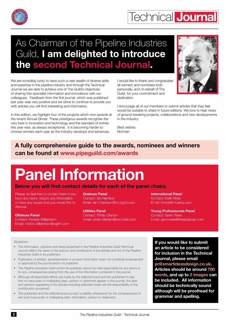
The High Density Infra-Red (HDIR) cladding process uses light emitted from a plasma arc lamp which is concentrated into a line focus at 500-3500W/cm2 to fuse and bond a layer of metal such as Inconel 625, Inconel 825, stainless steel, to a structural backing metal such as X65 pipe. In the CermaClad™ process, a metal precursor powder is applied as a paint to the surface to be clad (such as seamless pipe), and then the surface is scanned with an arc lamp to fuse and metallurgically bond the cladding. The arc lamp (Figure 1a) produces an intense, indirect heat capable of heating a surface at rates exceeding 1,000,000 degrees/second, but without the electrode and Marangoni
convective stirring effects of GMAW and laser welding processes, leading to lower weld dilution (higher purity overlays).
Under a cooperative agreement with Petrobras (NYSE: PBR), the design of the lamp was miniaturized and modified for cladding inside a pipe as small as 8” in diameter, and is represented in Figure 1b.
Fig. 1a) Operating principle (courtesy Vortek-Mattson industries) b) Setup for cladding inside a pipe
The value propositions of the CermaClad™ technology are: faster application rate (15 – 80 times faster than conventional laser/weld cladding processes), true metallurgical bond (bond strength > 75,000 psi), low overlay dilution with iron, ability to produce metallurgically bonded clad seamless pipe, and no limitations on pipe wall thickness or upper diameter. This technology is suitable for the production of stainless and CRA clad seamless and prefabricated pipes in diameters 8” to 36”, and with wall thicknesses from 0.25” to 2” and higher. Both CRA and wear resistant alloys such as chrome carbide and WC Metal matrix composite overlays can be applied
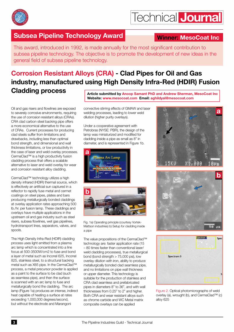
Figure 2. Optical photomicrographs of weld overlay (a), wrought (b), and CermaClad™ (c) alloy 625
Article submitted by Anoop Samant PhD and Andrew Sherman, MesoCoat Inc Website: www.mesocoat.com Email: [email protected]
This award, introduced in 1992, is made annually for the most significant contribution to subsea pipeline technology. The objective is to promote the development of new ideas in the general field of subsea pipeline technology.
Winner: MesoCoat Inc
a
b
a
b
Technical Journal
Utility Pipeline Technology Award
JD7 Pipescan+ - a new generation survey tool
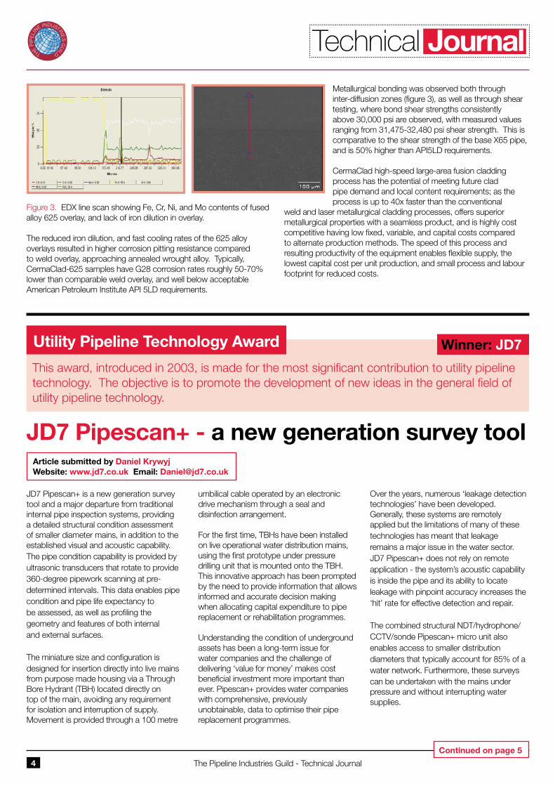
JD7 Pipescan+ is a new generation survey tool and a major departure from traditional internal pipe inspection systems, providing a detailed structural condition assessment of smaller diameter mains, in addition to the established visual and acoustic capability. The pipe condition capability is provided by ultrasonic transducers that rotate to provide 360-degree pipework scanning at pre-determined intervals. This data enables pipe condition and pipe life expectancy to be assessed, as well as profiling the geometry and features of both internal and external surfaces.
The miniature size and configuration is designed for insertion directly into live mains from purpose made housing via a Through Bore Hydrant (TBH) located directly on top of the main, avoiding any requirement for isolation and interruption of supply. Movement is provided through a 100 metre
umbilical cable operated by an electronic drive mechanism through a seal and disinfection arrangement.
For the first time, TBHs have been installed on live operational water distribution mains, using the first prototype under pressure drilling unit that is mounted onto the TBH. This innovative approach has been prompted by the need to provide information that allows informed and accurate decision making when allocating capital expenditure to pipe replacement or rehabilitation programmes.
Understanding the condition of underground assets has been a long-term issue for water companies and the challenge of delivering ‘value for money’ makes cost beneficial investment more important than ever. Pipescan+ provides water companies with comprehensive, previously unobtainable, data to optimise their pipe replacement programmes.
Over the years, numerous ‘leakage detection technologies’ have been developed. Generally, these systems are remotely applied but the limitations of many of these technologies has meant that leakage remains a major issue in the water sector. JD7 Pipescan+ does not rely on remote application - the system’s acoustic capability is inside the pipe and its ability to locate leakage with pinpoint accuracy increases the ‘hit’ rate for effective detection and repair.
The combined structural NDT/hydrophone/CCTV/sonde Pipescan+ micro unit also enables access to smaller distribution diameters that typically account for 85% of a water network. Furthermore, these surveys can be undertaken with the mains under pressure and without interrupting water supplies.
Article submitted by Daniel Krywyj Website: www.jd7.co.uk Email: [email protected]
This award, introduced in 2003, is made for the most significant contribution to utility pipeline technology. The objective is to promote the development of new ideas in the general field of utility pipeline technology.
Winner: JD7
The Pipeline Industries Guild - Technical Journal4
Figure 3. EDX line scan showing Fe, Cr, Ni, and Mo contents of fused alloy 625 overlay, and lack of iron dilution in overlay.
The reduced iron dilution, and fast cooling rates of the 625 alloy overlays resulted in higher corrosion pitting resistance compared to weld overlay, approaching annealed wrought alloy. Typically, CermaClad-625 samples have G28 corrosion rates roughly 50-70% lower than comparable weld overlay, and well below acceptable American Petroleum Institute API 5LD requirements.
Metallurgical bonding was observed both through inter-diffusion zones (figure 3), as well as through shear testing, where bond shear strengths consistently above 30,000 psi are observed, with measured values ranging from 31,475-32,480 psi shear strength. This is comparative to the shear strength of the base X65 pipe, and is 50% higher than API5LD requirements.
CermaClad high-speed large-area fusion cladding process has the potential of meeting future clad pipe demand and local content requirements; as the process is up to 40x faster than the conventional
weld and laser metallurgical cladding processes, offers superior metallurgical properties with a seamless product, and is highly cost competitive having low fixed, variable, and capital costs compared to alternate production methods. The speed of this process and resulting productivity of the equipment enables flexible supply, the lowest capital cost per unit production, and small process and labour footprint for reduced costs.
Continued on page 5
Technical Journal
The Pipeline Industries Guild - Technical Journal5
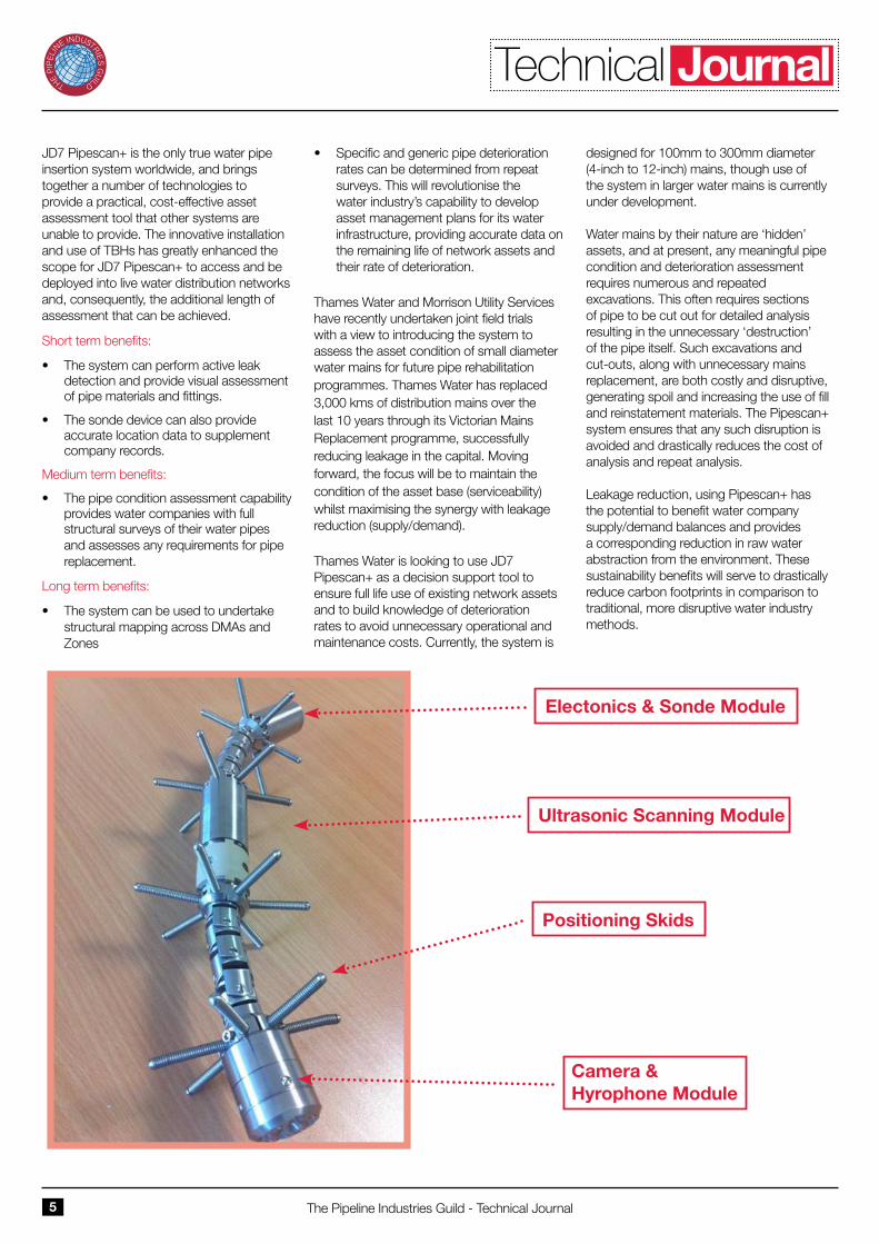
JD7 Pipescan+ is the only true water pipe insertion system worldwide, and brings together a number of technologies to provide a practical, cost-effective asset assessment tool that other systems are unable to provide. The innovative installation and use of TBHs has greatly enhanced the scope for JD7 Pipescan+ to access and be deployed into live water distribution networks and, consequently, the additional length of assessment that can be achieved.
Short term benefits:
• The system can perform active leak detection and provide visual assessment of pipe materials and fittings.
• The sonde device can also provide accurate location data to supplement company records.
Medium term benefits:
• The pipe condition assessment capability provides water companies with full structural surveys of their water pipes and assesses any requirements for pipe replacement.
Long term benefits:
• The system can be used to undertake structural mapping across DMAs and Zones
• Specific and generic pipe deterioration rates can be determined from repeat surveys. This will revolutionise the water industry’s capability to develop asset management plans for its water infrastructure, providing accurate data on the remaining life of network assets and their rate of deterioration.
Thames Water and Morrison Utility Services have recently undertaken joint field trials with a view to introducing the system to assess the asset condition of small diameter water mains for future pipe rehabilitation programmes. Thames Water has replaced 3,000 kms of distribution mains over the last 10 years through its Victorian Mains Replacement programme, successfully reducing leakage in the capital. Moving forward, the focus will be to maintain the condition of the asset base (serviceability) whilst maximising the synergy with leakage reduction (supply/demand).
Thames Water is looking to use JD7 Pipescan+ as a decision support tool to ensure full life use of existing network assets and to build knowledge of deterioration rates to avoid unnecessary operational and maintenance costs. Currently, the system is
designed for 100mm to 300mm diameter (4-inch to 12-inch) mains, though use of the system in larger water mains is currently under development.
Water mains by their nature are ‘hidden’ assets, and at present, any meaningful pipe condition and deterioration assessment requires numerous and repeated excavations. This often requires sections of pipe to be cut out for detailed analysis resulting in the unnecessary ‘destruction’ of the pipe itself. Such excavations and cut-outs, along with unnecessary mains replacement, are both costly and disruptive, generating spoil and increasing the use of fill and reinstatement materials. The Pipescan+ system ensures that any such disruption is avoided and drastically reduces the cost of analysis and repeat analysis.
Leakage reduction, using Pipescan+ has the potential to benefit water company supply/demand balances and provides a corresponding reduction in raw water abstraction from the environment. These sustainability benefits will serve to drastically reduce carbon footprints in comparison to traditional, more disruptive water industry methods.
Electonics & Sonde Module
Ultrasonic Scanning Module
Positioning Skids
Camera & Hyrophone Module
Technical Journal
Land Based Pipeline Technology Award
ZPV - New valve technology for reciprocating compressors that significantly reduces cost of operation
The Pipeline Industries Guild - Technical Journal6
The valves are the single most critical component in a reciprocating compressor that defines its reliability, power consumed and operating costs. 36% of all unscheduled shut downs are due to valve failures. In a high speed pipeline transmission application, more that 20% of the compressor power is used to push the gas through the valves. In conventional valves, the sealing elements (plate, poppet, rings) are typically actuated by helical coil springs.
Continuous impact on the valve seat and guard result in wear of the metal seat and guard and eventually leads to valve leakage. To correct this, valves have to be regularly serviced, which involves removing the valves from the compressor, replacing all the wearing internals (sealing elements, springs, plates and buttons), and precision machining the seat and guard. Typically after two machining operations, the entire valve has to be replaced. Service intervals for valves depend on compressor speed and application. In a high speed clean gas application, (transmission) the service interval can be as much as once a year. On the other end of the spectrum, in very dirty gas gathering, there are several cases where valves are serviced every week. Servicing of conventional valves is expensive, time consuming, and results in the additional expense of downtime and lost revenue. Customers tend to stock a large inventory of fully assembled valves to reduce this downtime. Conventional valve design has seen no significant development in the last 50 years other than changes to material and manufacturing.
The Zahroof Performance Valve (ZPV) represents a paradigm shift in valve reliability, performance, ease of service and operating cost. It is a drop-in replacement for conventional valves requiring no change to the compressor.
The ZPV consists of several standard modules that are held stationary between the valve seat and retainer. Each module is
an individual reed valve, with all the wear contained in the module, and is configured such that the flow path through the module is straight through without any deviations. The service of the valve is simplified to only replacing the modules: eliminating machining, skilled labour and the bulk of time. It takes 5 – 10 minutes to fully turn around a ZPV compared to more than 48 hours for a conventional valve. The straight flow path results in a measured reduction of more than 10% compressor power in transmission applications. This results in a direct saving in fuel costs of $46k per year per compressor or it could mean an increase in throughput of $30M per year per compressor for the same power (assuming $2.5/MSCF). It is a green technology as it is the quickest and most economical way to reduce emissions. Reliability is improved several fold by the innovative design that eliminates helical coil springs, keeps the plastic components stationary and subject only to compression stresses, and eliminates head on impact of liquids and solids in the flow stream with the plastic components. The use of standard size modules that can be used in all applications irrespective of the brand of compressor or cylinder results in at least an 80% reduction in inventory.
ZPVs can be applied in all reciprocating compressor applications. This includes the complete natural gas industry (production, gathering, transmission, storage, distribution, CNG, LNG, FPSO, etc.), CCS, chemical plants, air, H2, etc. It is ideally suited to shale gas production.
The valve design, optimized with CFD (Ansys CFX) and FEA (Ansys) has been tested thoroughly over two years in the lab and in the field. Lab testing included continuous operation in an air compressor for 3.5 months, running at 3600 rpm and 9.0 pressure ratio (450 F discharge temperature).
The ZPVs have been installed in working compressor stations where the 10% compressor power reduction was measured
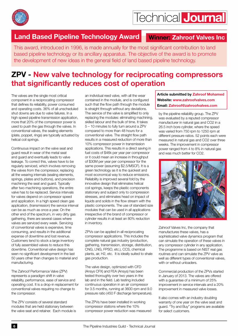
by the pipeline reliability group. The ZPV was evaluated by a reputed compressor manufacturer in natural gas and CO2 in a 26.5 inch bore cylinder, where the speed was varied from 750 rpm to 1250 rpm at different pressure ratios. 52 points each were measured in natural gas and CO2 over three weeks. The improvement in compressor power ranged from 4 to 8% in natural gas and was much better for CO2.
Zahroof Valves Inc, the company that manufactures these valves, has a sophisticated valve dynamics program that can simulate the operation of these valves in any compressor cylinder in any application. The programme is based on NIST real gas routines and can simulate the ZPV valve as well as different types of conventional valves, with or without unloaders.
Commercial production of the ZPVs started in January of 2013. The valves are offered with a guarantee of a minimum of 25% improvement in service intervals and a 20% improvement in measured valve losses.
It also comes with an industry doubling warranty of one year on the valve seat and guard. “Try and Buy” programs are available for select customers.
Article submitted by Zahroof Mohamed
Website: www.zahroofvalves.com
Email: [email protected]
This award, introduced in 1996, is made annually for the most significant contribution to land based pipeline technology or its ancillary apparatus. The objective of the award is to promote the development of new ideas in the general field of land based pipeline technology.
Winner: Zahroof Valves Inc
Technical Journal
J.W.Jones Memorial Award
Degradation of Polyethylene Pipes
The Pipeline Industries Guild - Technical Journal7
ABSTRACT
The water industry requires a method of determining the remaining in-service life of assets that it already has in the field. This knowledge allows for successful asset management and appropriate capital expenditure (i.e. pipes that do not need replacing are left in-service). As the first polyethylene mains reach their initial design life, this requirement will only increase. This is particularly important when pipes are beneath busy streets and affect a large number of customers. This paper presents a new approach to this problem, by performing small scale chemical evaluation on the polyethylene pipe to determine the state of degradation in the pipe.
Ageing using the full notch creep test (FNCT) method was carried out on a polyethylene blend taken from pipe rated as PE100. Samples were aged to failure at varying stress levels and temperatures and also stopped at known times before failure. These samples were then thoroughly evaluated to find their crystallinity, oxidation induction temperature, peak melt temperature, density, carbonyl index, hydroperoxide content and molecular weight distribution. Samples were also examined using scanning electron microscopy; this allowed a more accurate insight into the mode of failure and also of crack development over time for the un-failed samples.
Using this information a model of these chemical markers over the lifetime of the samples was produced. From this initial model a test methodology was proposed so that small scale tests can be performed on pipes and an approximate time to “high risk of failure” can be determined.
INTRODUCTION
In the 1960s plastic polyethylene pipes began to be introduced in the UK, initially for new communication pipes. New, improved polyethylene pipe material for both mains and communication pipe sizes were brought into service in the 1980s and 1990s and these exhibited even better working properties. As of 2010, 15% of the estimated 345,000km of water mains in the UK were polyethylene pipe [1] and this proportion is increasing.
There has been a significant amount of research carried out to obtain the overall life time of these new polyethylene pipes [2-5], but relatively little which considers pipes currently in-service [6]. With a large amount of new polyethylene pipe being added to the water distribution network yearly, it is important for water companies to be able to predict when a pipe will need to be replaced. This helps with planning and cost management, as well as preventing leaks and bursts, which cause disruption and damage consumer-supplier relationships.It is difficult to replicate how a pipe degrades in-service, since the failure modes of interest are expected to take over 100 years to occur. Hence, acceleration and extrapolation techniques need to be employed in order to obtain accurate predictions. These predictions can then be used to help plan when certain pipes are likely to fail and need replacing.
Currently, areas of high leakage and burst rate are monitored and pipes replaced as and when required. However, a system which would allow an insight into the mechanical and chemical properties of the pipes is not currently available. The ability to measure the properties of the pipes would
allow the amount of deterioration to be determined and monitored. There is a need for a prediction tool which can be used to determine the probable remaining lifetime of a polyethylene water pipe.
The principal aim of the project was to develop a method that could be used by water utilities to predict the probable remaining in-service lifetime of a given polyethylene pipe in the network. As well as the remaining time, the age of the pipes was also required to be determined. Pipes in-service were not available for testing, as they couldn’t be exhumed for this project and also material aged naturally for a significant amount of time does not exist. The method must, therefore, be obtained using acceleration techniques and extrapolation to in-service conditions. Acceleration techniques were employed so that the planned works could be completed within the time available. The selected method had to be feasible for the water utilities. This led to a requirement that the test methods be repeatable, easily setup in existing test facilities, simple to carry out, relatively cheap to perform and most importantly safe to perform.
METHODOLOGY
Virgin PE100 SDR 17 pipe with outer diameter 160mm pipes, were manufactured into full notch creep test (FNCT) samples and aged at 65°C and 80°C in a 2% (by weight) Arkopal environment under different stress levels. These samples were aged to failure and an approximate extrapolation performed (ISO 9080). The failed samples were then analysed to determine the amount of degradation that had occurred.
Article submitted by Joseph Sanders, Senior Asset Engineer, Affinity Water
Website: www.affinitywater.co.uk Email: [email protected]
The J.W.Jones award is awarded every two years to the author(s) of a paper presented to a branch technical meeting which best meets the award criteria (available from the Guild). Among the aims of this award is the encouragement of younger authors, although no age limit is imposed. The award is made in honour of the eponymous founder of the Guild and its first Chairman who died in 1971.
Winner: Joseph Sanders, Affinity Water
Technical Journal
The Pipeline Industries Guild - Technical Journal8
These techniques have been described previously [5,6,9] and include methods to measure anti-oxidant concentration, carbonyl content, molecular weight, crystallinity, melt temperature and hydroperoxide ions concentration. These allowed an insight into how apt the chemical markers are at determining the remaining in-service life of the pipe. The samples were also analysed using a scanning electron microscope, so that the crack progression could be determined and the mode of failure analysed. Test methods were compared to current condition assessment of ferrous mains with regards to cost, time and repeatability.
THE PROPOSED METHOD
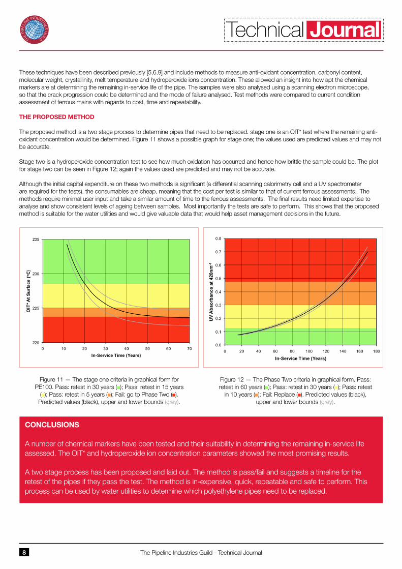
The proposed method is a two stage process to determine pipes that need to be replaced. stage one is an OIT* test where the remaining anti-oxidant concentration would be determined. Figure 11 shows a possible graph for stage one; the values used are predicted values and may not be accurate.
Stage two is a hydroperoxide concentration test to see how much oxidation has occurred and hence how brittle the sample could be. The plot for stage two can be seen in Figure 12; again the values used are predicted and may not be accurate.
Although the initial capital expenditure on these two methods is significant (a differential scanning calorimetry cell and a UV spectrometer are required for the tests), the consumables are cheap, meaning that the cost per test is similar to that of current ferrous assessments. The methods require minimal user input and take a similar amount of time to the ferrous assessments. The final results need limited expertise to analyse and show consistent levels of ageing between samples. Most importantly the tests are safe to perform. This shows that the proposed method is suitable for the water utilities and would give valuable data that would help asset management decisions in the future.
Figure 11 — The stage one criteria in graphical form for PE100. Pass: retest in 30 years (n); Pass: retest in 15 years
(n); Pass: retest in 5 years (n); Fail: go to Phase Two (n). Predicted values (black), upper and lower bounds (grey).
Figure 12 — The Phase Two criteria in graphical form. Pass: retest in 60 years (n); Pass: retest in 30 years (n); Pass: retest
in 10 years (n); Fail: Replace (n). Predicted values (black), upper and lower bounds (grey).
CONCLUSIONS
A number of chemical markers have been tested and their suitability in determining the remaining in-service life assessed. The OIT* and hydroperoxide ion concentration parameters showed the most promising results.
A two stage process has been proposed and laid out. The method is pass/fail and suggests a timeline for the retest of the pipes if they pass the test. The method is in-expensive, quick, repeatable and safe to perform. This process can be used by water utilities to determine which polyethylene pipes need to be replaced.
Technical Journal