cds12honorsenglish.files.wordpress.com · Created Date: 5/12/2015 10:33:48 AM

Journal of Mechanical Engineering Vol 17(1), 33-48, 2020
___________________
ISSN 1823-5514, eISSN2550-164X Received for review: 2018-11-14
© 2020 Faculty of Mechanical Engineering, Accepted for publication:2019-12-19
UniversitiTeknologi MARA (UiTM), Malaysia. Published:2020-04-01
Effect of Process Parameters on Surface Roughness in HPC Drilling
of AISI 1055 Steel
H.V. Shete*
Ashokrao Mane Group of Institutions,
Department of Mechanical Engineering,
Kolhapur-416 112, Maharashtra, India
M.S. Sohani
Shaikh College of Engineering and Technology,
Belagavi, Karnataka, India
ABSTRACT
Data regarding the influence of high-pressure coolant on the performance of
drilling process using design of experiment has been limitedly available. This
paper presents the effect of higher coolant pressures along with spindle
speed, feed rate and peck depth on the surface roughness of hole using
Taguchi technique. Experimental set up was developed consisting of
specially manufactured high-pressure coolant system and high-pressure
adapter assembly attached to vertical machining center. Developed
experimental set up has optimized utilization of non-through coolant vertical
machining center in a small-scale industry. Experiments were conducted on
AISI 1055 steel with TiAIN coated drill on the vertical machining center.
Taguchi technique was used for design of experiment and analysis of results.
Results revealed that the surface roughness improve till coolant pressure
reaches to an optimum value of 13.5 bar and there after it decreases.
Coolant pressure and spindle speed was the significant process parameters
for the hole surface roughness. Surface roughness at the top of hole was
considerably lower than the bottom of hole, under the action of all process
parameters. Supply of coolant at high pressure has resulted in lower surface
roughness even with large peck depth; which indicate that, manufacturing
cost can be reduced with the use of high-pressure coolant in drilling.
Keywords: High Pressure Coolant (HPC); High Pressure Coolant System;
Adapter Assembly; Taguchi Method

Effect of Process Parameters on Surface Roughness in HPC Drilling of AISI 1055 Steel
34
Introduction
High pressure cooling, cryogenic cooling [1,2] and atomized coolant spray
[3,4] are the most focused trends in the manufacturing research [5].Various
researchers have studied the high-pressure coolant machining. Lopez de
Lacalle et al. [6] studied the influence of HPC in drilling of Inconel 718 and
Ti6A14V. HPC drilling with internal coolant showed better tool life than the
conventional coolant drilling, even at high cutting speeds. Dhar et al. [7]
concluded that HPC drilling results in lesser roundness deviation.
Bermingham et al. [8] conducted drilling experiments on Ti-6Al-4V with
WC-Co drill at 70 bar coolant pressure and concluded that the productivity
and tool life was substantially improved with HPC.
Jessy et al. [9] investigated the influence of coolant supplied in the
range of 0.01 to 0.03 bar pressure and revealed that, internal coolant drilling
results in considerable reduction of drill temperature than the external coolant
drilling. Bagci and Ozcelik [10] studied the impact of an internal air coolant
supplied at 1 bar and 3 bar pressure and revealed that, the coolant pressure
has greater influence on the drill temperature. Li et al. [11] analyzed drilling
of Ti alloy with spiral point drill at 2 bar coolant pressure. The study
emphasized the scope for research work in HPC drilling. Shete and Sohani
[12] showed that the drilling at the bottom of hole was more critical that the
top of hole. D’Addona and Raykar [13] concluded that, coolant pressure has
a considerable influence on the tool temperature and higher coolant pressure
results in efficient cooling and effective lubrication action at the cutting zone.
Tanabe and Hoshino [14] developed a new forced cooling technology for
machining difficult-to-machine material and concluded that the technology
effectively cools the tool tip and removes the chips. Arunkumar et al. [15]
investigated effects of deep hole drilling parameters on the hole quality and
concluded that the coolant pressure, spindle speed are the significant
parameters affecting on the surface roughness, circularity and cylindricity of
hole. Oezkaya and Biermann [16] investigated the velocity, kinetic energy
and distribution of coolant oil at the cutting edges and in the clearance
between tool flute and work piece in deep drilling process of AISI 316L. The
study concluded that heat generated between tool, work piece and chip
cannot be removed satisfactorily, due to reduced flow velocity of coolant
during drilling.
The literature survey revealed that, study pertaining to the HPC
drilling has been limited to the use of a constant high-pressure coolant and
pinpointed on the necessity of investigation on the effect of HPC in drilling
process using design of experiment [17]. Hence, present study aims to
determine the effect of variation of high pressure of coolant, spindle speed,
feed rate and peck depth on the surface roughness of hole in drilling using
Taguchi Technique. The present work involves the development of an
experimental set up, so as to boost the productivity in small scale industries.
H.V. Shete and M.S. Sohani
35
The investigation has been performed to obtain the optimal process
parameters of drilling process, which results in reduced surface roughness
and manufacturing cost.
Experimental Set Up
Drilling operation constitutes, drilling throughout holes of diameter 10 mm
and depth 55 mm in AISI 1055 steel workpieces of Ø 20x55 mm dimension.
The specifications of solid coated carbide drill [18] are shown in Table 1.
Semi synthetic coolant was selected, as it is widely used in manufacturing
industries. Specifications of the coolant are shown in Table 2.
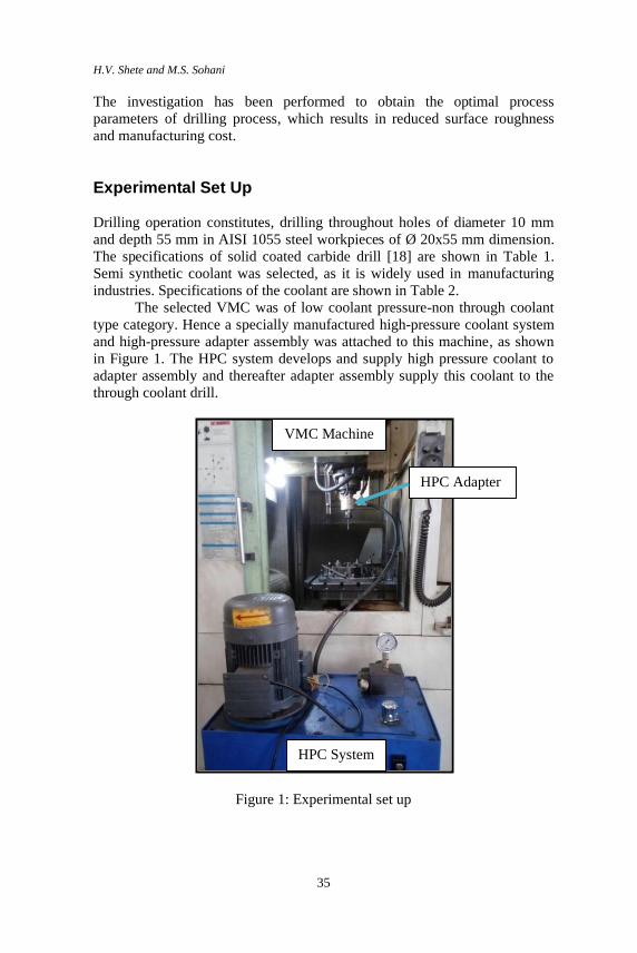
The selected VMC was of low coolant pressure-non through coolant
type category. Hence a specially manufactured high-pressure coolant system
and high-pressure adapter assembly was attached to this machine, as shown
in Figure 1. The HPC system develops and supply high pressure coolant to
adapter assembly and thereafter adapter assembly supply this coolant to the
through coolant drill.
Figure 1: Experimental set up
VMC Machine
HPC Adapter
HPC System
Effect of Process Parameters on Surface Roughness in HPC Drilling of AISI 1055 Steel
36
The experimental set up was developed specially for the VMC machines,
which are not having inbuilt through coolant drilling or milling facility. Thus,
it optimizes the utilization of existing non-through coolant VMC’s in small
and medium scale manufacturing industries.
Table 1: Specifications of through coolant drill
Tool material Coating Drill diameter
(mm)
Flute length
(mm)
Point angle
( ⁰ )
Micro grain carbide TiAIN 10 61 140
Table 2: Specifications of the coolant
Type Grade PH
(3% solution)
Coolant
concentration
Semi synthetic
coolant
Tectyl cool
260B -9.7 3%
Design of Experiment
Taguchi method is commonly used for the design of experiment [9, 10]. In
the present investigation, four process parameters were selected and their
range was selected, so as to maximize the production rate. Range and levels
of input process parameters are shown in Table 3. The L9 orthogonal array
was selected, which consists of nine rows and four columns as shown in
Table 4.
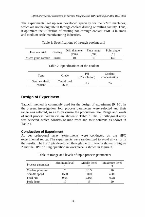
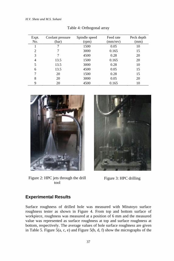
Conduction of Experiment As per orthogonal array, experiments were conducted on the HPC
experimental set up. The experiments were randomized to avoid any error in
the results. The HPC jets developed through the drill tool is shown in Figure
2 and the HPC drilling operation in workpiece is shown in Figure 3.
Table 3: Range and levels of input process parameters
Process parameter Minimum level
1
Middle level
2
Maximum level
3
Coolant pressure 7 13.5 20
Spindle speed 1500 3000 4500
Feed rate 0.05 0.165 0.28
Peck depth 10 15 20
H.V. Shete and M.S. Sohani
37
Table 4: Orthogonal array
Expt.
No.
Coolant pressure
(bar)
Spindle speed
(rpm)
Feed rate
(mm/rev)
Peck depth
(mm)
1 7 1500 0.05 10
2 7 3000 0.165 15
3 7 4500 0.28 20
4 13.5 1500 0.165 20
5 13.5 3000 0.28 10
6 13.5 4500 0.05 15
7 20 1500 0.28 15
8 20 3000 0.05 20
9 20 4500 0.165 10
Figure 2: HPC jets through the drill
tool
Figure 3: HPC drilling
Experimental Results
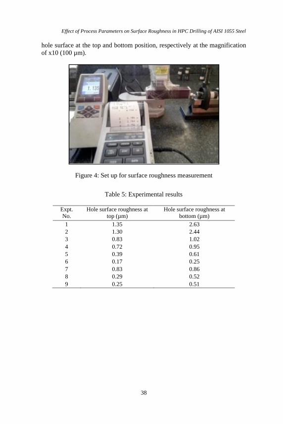
Surface roughness of drilled hole was measured with Mitutoyo surface
roughness tester as shown in Figure 4. From top and bottom surface of
workpiece, roughness was measured at a position of 6 mm and the measured
value was represented as surface roughness at top and surface roughness at
bottom, respectively. The average values of hole surface roughness are given
in Table 5. Figure 5(a, c, e) and Figure 5(b, d, f) show the micrographs of the
Effect of Process Parameters on Surface Roughness in HPC Drilling of AISI 1055 Steel
38
hole surface at the top and bottom position, respectively at the magnification
of x10 (100 µm).
Figure 4: Set up for surface roughness measurement
Table 5: Experimental results
Expt.
No.
Hole surface roughness at
top (µm)
Hole surface roughness at
bottom (µm)
1 1.35 2.63
2 1.30 2.44
3 0.83 1.02
4 0.72 0.95
5 0.39 0.61
6 0.17 0.25
7 0.83 0.86
8 0.29 0.52
9 0.25 0.51

H.V. Shete and M.S. Sohani
39
(a) (b)
Experiment No. 3: coolant pressure: 7 bar; spindle speed: 4500 rpm; feed
rate: 0.28 mm/rev; peck depth: 20 mm
(c) (d)
Experiment No. 5: coolant pressure: 13.5 bar; spindle speed: 3000 rpm; feed
rate: 0.28 mm/rev; peck depth: 10 mm
(e) (f)
Experiment No. 9: coolant pressure: 20 bar; spindle speed: 4500 rpm; feed
rate: 0.165 mm/rev; peck depth: 10 mm
Figure 5: Micrograph of hole surface at top and bottom.
Effect of Process Parameters on Surface Roughness in HPC Drilling of AISI 1055 Steel
40
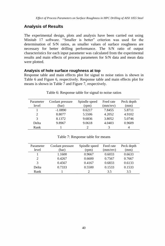
Analysis of Results
The experimental design, plots and analysis have been carried out using
Minitab 17 software. “Smaller is better” criterion was used for the
determination of S/N ratios, as smaller values of surface roughness are
necessary for better drilling performance. The S/N ratio of output
characteristics for each input parameter was calculated from the experimental
results and main effects of process parameters for S/N data and mean data
were plotted.
Analysis of hole surface roughness at top Response table and main effects plot for signal to noise ratios is shown in
Table 6 and Figure 6, respectively. Response table and main effects plot for
means is shown in Table 7 and Figure 7, respectively.
Table 6: Response table for signal to noise ratios
Parameter
level
Coolant pressure
(bar)
Spindle speed
(rpm)
Feed rate
(mm/rev)
Peck depth
(mm)
1 -1.0890 0.6217 7.8455 5.8711
2 8.8077 5.5506 4.2052 4.9102
3 8.1372 9.6836 3.8052 5.0746
Delta 9.8967 9.0618 4.0403 0.9609
Rank 1 2 3 4
Table 7: Response table for means
Parameter
level
Coolant pressure
(bar)
Spindle speed
(rpm)
Feed rate
(mm/rev)
Peck depth
(mm)
1 1.1600 0.9667 0.6033 0.6633
2 0.4267 0.6600 0.7567 0.7667
3 0.4567 0.4167 0.6833 0.6133
Delta 0.7333 0.5500 0.1533 0.1533
Rank 1 2 3.5 3.5
H.V. Shete and M.S. Sohani
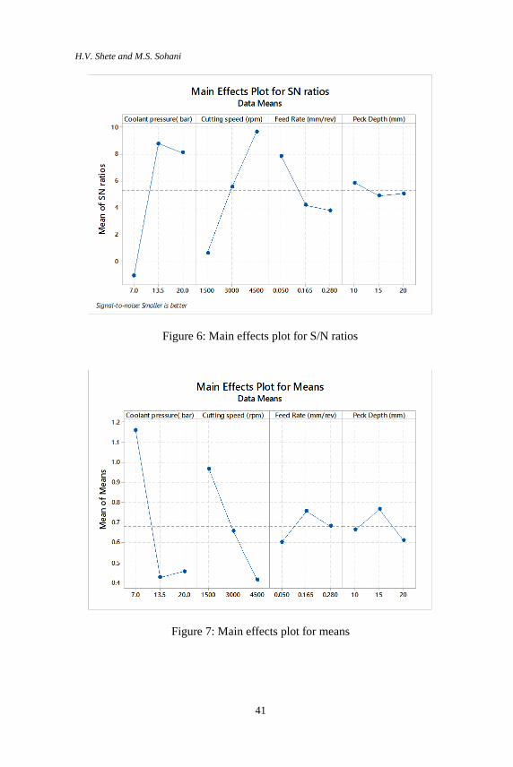
41
Figure 6: Main effects plot for S/N ratios
Figure 7: Main effects plot for means
Effect of Process Parameters on Surface Roughness in HPC Drilling of AISI 1055 Steel
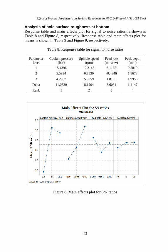
42
Analysis of hole surface roughness at bottom Response table and main effects plot for signal to noise ratios is shown in
Table 8 and Figure 8, respectively. Response table and main effects plot for
means is shown in Table 9 and Figure 9, respectively.
Table 8: Response table for signal to noise ratios
Parameter
level
Coolant pressure
(bar)
Spindle speed
(rpm)
Feed rate
(mm/rev)
Peck depth
(mm)
1 -5.4396 -2.2145 3.1185 0.5810
2 5.5934 0.7530 -0.4846 1.8678
3 4.2907 5.9059 1.8105 1.9956
Delta 11.0330 8.1204 3.6031 1.4147
Rank 1 2 3 4
Figure 8: Main effects plot for S/N ratios
H.V. Shete and M.S. Sohani
43
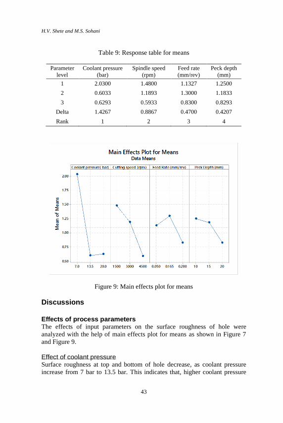
Table 9: Response table for means
Parameter
level
Coolant pressure
(bar)
Spindle speed
(rpm)
Feed rate
(mm/rev)
Peck depth
(mm)
1 2.0300 1.4800 1.1327 1.2500
2 0.6033 1.1893 1.3000 1.1833
3 0.6293 0.5933 0.8300 0.8293
Delta 1.4267 0.8867 0.4700 0.4207
Rank 1 2 3 4
Figure 9: Main effects plot for means
Discussions
Effects of process parameters The effects of input parameters on the surface roughness of hole were
analyzed with the help of main effects plot for means as shown in Figure 7
and Figure 9.
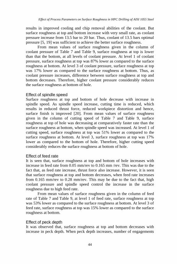
Effect of coolant pressure
Surface roughness at top and bottom of hole decrease, as coolant pressure
increase from 7 bar to 13.5 bar. This indicates that, higher coolant pressure
Effect of Process Parameters on Surface Roughness in HPC Drilling of AISI 1055 Steel
44
results in improved cooling and chip removal abilities of the coolant. But
surface roughness at top and bottom increase with very small rate, as coolant
pressure increase from 13.5 bar to 20 bar. Thus, coolant of 13.5 bars optimal
pressure [5, 19] was sufficient to achieve the better surface roughness.
From mean values of surface roughness given in the column of
coolant pressure of Table 7 and Table 9, surface roughness at top is lower
than that the bottom, at all levels of coolant pressure. At level 1 of coolant
pressure, surface roughness at top was 87% lower as compared to the surface
roughness at bottom. At level 3 of coolant pressure, surface roughness at top
was 17% lower as compared to the surface roughness at bottom. Thus, as
coolant pressure increases, difference between surface roughness at top and
bottom decreases. Therefore, higher coolant pressure considerably reduces
the surface roughness at bottom of hole.
Effect of spindle speed Surface roughness at top and bottom of hole decrease with increase in
spindle speed. As spindle speed increase, cutting time is reduced, which
results in reduced thrust force, reduced workpiece distortion and hence,
surface finish is improved [20]. From mean values of surface roughness
given in the column of cutting speed of Table 7 and Table 9, surface
roughness at top of hole was decreasing at comparatively faster rate than the
surface roughness at bottom, when spindle speed was increased. At level 1 of
cutting speed, surface roughness at top was 51% lower as compared to the
surface roughness at bottom. At level 3, surface roughness at top was 17%
lower as compared to the bottom of hole. Therefore, higher cutting speed
considerably reduces the surface roughness at bottom of hole.
Effect of feed rate It is seen that, surface roughness at top and bottom of hole increases with
increase in feed rate from 0.05 mm/rev to 0.165 mm /rev. This was due to the
fact that, as feed rate increase, thrust force also increase. However, it is seen
that surface roughness at top and bottom decreases, when feed rate increases
from 0.165 mm/rev to 0.28 mm/rev. This may be due to the fact that, high
coolant pressure and spindle speed control the increase in the surface
roughness due to high feed rate.
From mean values of surface roughness given in the column of feed
rate of Table 7 and Table 9, at level 1 of feed rate, surface roughness at top
was 53% lower as compared to the surface roughness at bottom. At level 3 of
feed rate, surface roughness at top was 15% lower as compared to the surface
roughness at bottom.
Effect of peck depth It was observed that, surface roughness at top and bottom decreases with
increase in peck depth. When peck depth increases, number of engagements

H.V. Shete and M.S. Sohani
45
and retractions of drill tool decreases, which results in reduced impact
stresses and hence, surface roughness decreases. It indicates that, use of
higher coolant pressure in drilling allow higher peck depth for lower surface
roughness, which can reduce the cycle time and production cost.
From mean values of surface roughness shown in the peck depth
column of Table 7 and Table 9 at level 1, surface roughness at top was 59%
lower as compared to the surface roughness at bottom. At level 3, surface
roughness at top was 21% lower as compared to the surface roughness at
bottom.
Comparative effects Based on the discussion of effects of process parameters on the surface
roughness and Table 5, it is concluded that the surface roughness at the
bottom was considerably higher than the top, which is also supported by the
micrographs of the hole surface shown in Figure 5. The micrographs show
that, hole surface at the bottom has more feed mark, chip marks, smearing
and distorted area than the surface at top. This was due the fact that, higher
temperature, vibrations and chip accumulation at the bottom of hole results in
more distortion of the drilled hole surface. Also from Table 5, in few cases
surface roughness values obtained with HPC drilling were considerably low
and competitive with finishing operations.
Significant parameters From the delta values of surface roughness and ranks shown in Table 7 and
Table 9 of response table for means, significant factors affecting on the surface roughness were determined. It was observed that, coolant pressure
followed by spindle speed was significant input parameters for the surface
roughness at the top and bottom of hole.
Optimal level of process parameters Main effects plot for S/N ratios were used to obtain the most favorable values
of process parameters [21]. The level of a parameter with highest signal to
noise ratio provide the optimal level [22]. Thus from Figure 7 and Figure 9,
optimal levels of parameters for HPC drilling at the top and bottom of hole
are shown in Table 10. It is seen that, optimal value of peck depth was
different at the top and bottom of hole, which is not possible from the
production point of view. Therefore, practically feasible optimal level of
process parameters for the undertaken HPC drilling process is also shown in
Table 10.
Effect of Process Parameters on Surface Roughness in HPC Drilling of AISI 1055 Steel
46
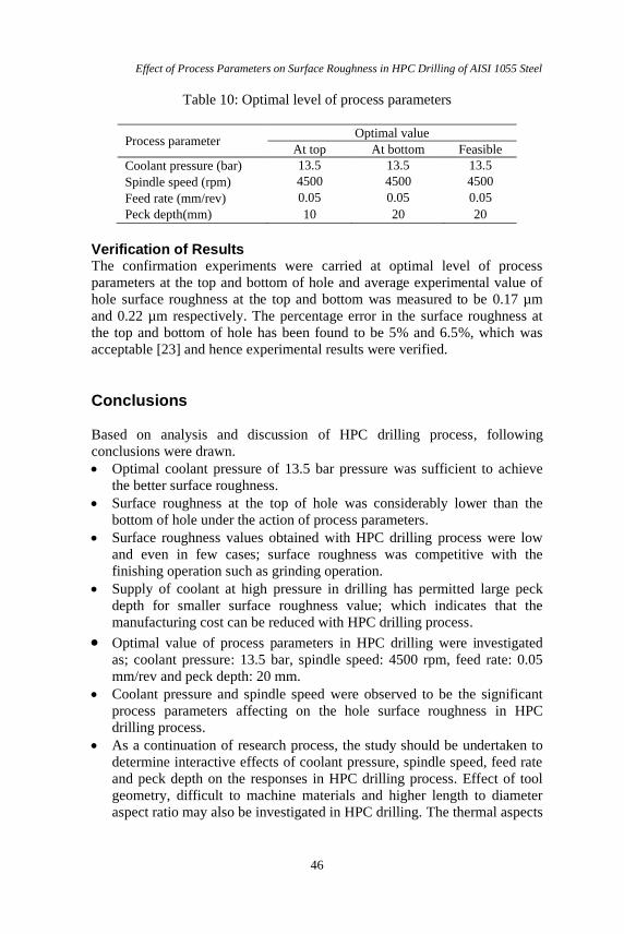
Table 10: Optimal level of process parameters
Process parameter Optimal value
At top At bottom Feasible
Coolant pressure (bar) 13.5
13.5
13.5
Spindle speed (rpm) 4500
4500
4500
Feed rate (mm/rev) 0.05
0.05
0.05
Peck depth(mm) 10
20
20
Verification of Results The confirmation experiments were carried at optimal level of process
parameters at the top and bottom of hole and average experimental value of
hole surface roughness at the top and bottom was measured to be 0.17 µm
and 0.22 µm respectively. The percentage error in the surface roughness at
the top and bottom of hole has been found to be 5% and 6.5%, which was
acceptable [23] and hence experimental results were verified.
Conclusions
Based on analysis and discussion of HPC drilling process, following
conclusions were drawn.
• Optimal coolant pressure of 13.5 bar pressure was sufficient to achieve
the better surface roughness.
• Surface roughness at the top of hole was considerably lower than the
bottom of hole under the action of process parameters.
• Surface roughness values obtained with HPC drilling process were low
and even in few cases; surface roughness was competitive with the
finishing operation such as grinding operation.
• Supply of coolant at high pressure in drilling has permitted large peck
depth for smaller surface roughness value; which indicates that the
manufacturing cost can be reduced with HPC drilling process.
• Optimal value of process parameters in HPC drilling were investigated
as; coolant pressure: 13.5 bar, spindle speed: 4500 rpm, feed rate: 0.05
mm/rev and peck depth: 20 mm. • Coolant pressure and spindle speed were observed to be the significant
process parameters affecting on the hole surface roughness in HPC
drilling process.
• As a continuation of research process, the study should be undertaken to
determine interactive effects of coolant pressure, spindle speed, feed rate
and peck depth on the responses in HPC drilling process. Effect of tool
geometry, difficult to machine materials and higher length to diameter
aspect ratio may also be investigated in HPC drilling. The thermal aspects
H.V. Shete and M.S. Sohani
47
of coolant, tool and chip during deep hole drilling must be investigated to
explore the insights of HPC drilling process.
References
[1] B.D. Jerold and M.P. Kumar, “The influence of cryogenic coolants in
machining ofTi-6V-4V”, Journal of Manufacturing Science and
Engineering 135 (3), 1-8 (2005).
[2] N. Govindraju, L.S. Ahmed, and M.P. Kumar, “Experimental
investigations on cryogenic cooling in the drilling of AISI 1045Steel”,
Materials and Manufacturing Processes 29 (11-12), 1417-1421 (2014).
[3] Lopez de Lacalle, C.Angulo, and A. Lamikiz, “Experimental and
numerical investigations of the effect of spray cutting fluids in high
speed milling”, Journal of Materials Processing Technology 172 (1),
11-15 (2006).
[4] C. Nath, S.G. Kapoor, A.K. Srivastava, and J. Iverson, “Study of
droplet spray behavior of an atomization-based cutting fluid spray
system for machining titanium alloys”, Journal of Manufacturing
Science and Engineering 136 (2), 1-12 (2014).
[5] P. Blau, K. Busch, M. Dix, C. Hochmuth, A. Stall, and R. Wertheim,“
Flushing strategies for high performance, efficient and environmentally
friendly cutting”, Procedia CIRP 26, 361-366 (2015).
[6] L.N.Lopez de Lacalle, B.J. Perez, J.A. Sanchez, J.I. Llorente, A.
Gutierrez, and J. Alboniga, “Using high pressure coolant in the drilling
and turning low mach inability alloys”, The International Journal of
Advanced Manufacturing Technology 16 (2), 85-91 (2000).
[7] N.R. Dhar, M.H. Rashid, and A.T. Siddiqui, “Effect of high pressure
coolant on chip, roundness deviation and tool wear in drilling AISI-
4340”, ARPN Journal of Engineering and Applied Science 1(3), 52-59
(2006).
[8] M.J. Bermingham, S. Palaniswamy, D. Morr, R. Andrews,and M.S.
Dargusch, “Advantages of milling and drilling Ti-6Al-4V components
with high pressure coolant”, International Journal of Advanced
Manufacturing Technology 72 (1-4), 77-88 (2014).
[9] K. Jessy, S.S. Kumar, D. Dinakaran, and V.S. Rao, “Influence of
different cooling methods on drill temperature in drilling GFRP”,
International Journal of Advanced Manufacturing Technology 76(1-4),
609-621 (2014).
[10] E. Bagciand B. Ozcelik, “Effects of different cooling conditions ontwist
drill temperature”, InternationalJournal of Advanced Manufacturing
Technology 34 (9-10), 867-877 (2006).
[11] R. Li, P. Hegde, and A.J. Shih, “High throughput drilling of
titaniumalloys”,International Journal of Machine Tools and
Manufacture 47(1), 63-74, 2007.
Effect of Process Parameters on Surface Roughness in HPC Drilling of AISI 1055 Steel
48
[12] H.V. Shete and M.S. Sohani, “Effect of process parameters on
holediameter accuracy in high pressure through coolant peck drilling
using Taguchi Technique”, International Journal of Material Forming
and Machining Processes- IGI Global 5(1), 12-31 (2018).
[13] D.M. D’Addona and S.J. Raikar, “Thermal modeling of tool
temperature distribution during high pressure coolant assisted turning of
Inconel 718”, Materials 12(3), 408 (2019).
[14] I. Tanabe and H. Hoshino, “Development of a new forced cooling
technology using a high-pressure coolant for machining difficult-to-
machine materials”, Journal of Manufacturing and Materials Processing
2 (2), 39, 2018.
[15] N. Arun kumar, A. Thanikasalam,V. Sankaranarayana, and E. Senthil
Kumar, “Parametric optimization of deep-hole drilling on AISI 1045
steel and online tool condition monitoring using an accelerometer,”
Journal of Materials and Manufacturing processes 33 (16), 1751-1764
(2018).
[16] E. Oezkaya and D. Biermann, “Experimental and simulative
investigation of the oil distribution during a deep-hole drilling process
and comparing of the RANS k-w-SST and RANS hybrid SAS-SST
turbulence model”, Thermal Science and Engineering 1(4), 874 (2018).
[17] H.V. Shete and M.S. Sohani, “Machining in high pressure coolant
environment–A strategy to improve machining performance: a review”,
International Journal of Manufacturing Technology and Management,
Inderscience Publication.
[18] F. Klocke, L. Settinen, D. Lung, P.C. Priarno, and M. Arft, “High performance cutting of gamma titanium aluminizes: Influence of
lubricoolant strategy on tool wear and surface integrity”, Wear 302 (1-
2), 11361144 (2013).
[19] E.O. Ezugwu and J. Bonney, “Effect of high pressure coolant supply
when machining nickel-base Inconel 718 alloy with coated carbide
tool”, Journal of Materials Processing Technology 153-154, 1045-1050
(2004).
[20] A. Kamboj, S. Kumar, and H. Singh, “Burr height and hole diameter
error minimization in drilling of AL6063/15%/SiC composites using
HSS step drills”, Journal of Mechanical Science and Technology 29 (7),
2837-2846 (2015).
[21] P.J. Ross, Taguchi techniques for quality engineering, 2nd ed. (Mc-
Graw Hill Education (India) Private Limited, New Delhi, 2005).
[22] R.K. Roy, A primer on Taguchi method, 2nd ed. (Society of
Manufacturing Engineers, Michigan, 2010).
[23] K.H. Hashmi, G. Zakria, M.B. Raza, and S. Khalil, “Optimization of
process parameters for high speed machining of Ti-6Al-4V using
response surface methodology”, International Journal of Advanced
Manufacturing Technology 85(5-8), 1847-1856 (2016).