Journal of Materials Chemistry...
7
Chemical bonding at the metal–organic framework/metal oxide interface: simulated epitaxial growth of MOF-5 on rutile TiO 2 † Jessica K. Bristow, a Keith T. Butler, a Katrine L. Svane, a Julian D. Gale * b and Aron Walsh * cd Thin-film deposition of metal–organic frameworks (MOFs) is now possible, but little is known regarding the microscopic nature of hybrid hetero-interfaces. We first assess optimal substrate combinations for coherent epitaxy of MOFs based on a lattice matching procedure. We then perform a detailed quantum mechanical/molecular mechanical investigation of the growth of (011) MOF-5 on (110) rutile TiO 2 . The lowest energy interface configuration involves a bidentate connection between two TiO 6 polyhedra with deprotonation of terephthalic acid to a bridging oxide site. The epitaxy of MOF-5 on the surface of TiO 2 was modelled with a forcefield parameterised to quantum chemical binding energies and bond lengths. The microscopic interface structure and chemical bonding characteristics are expected to be relevant to other hybrid framework-oxide combinations. 1 Introduction Metal–organic frameworks (MOFs) are formed of inorganic metal clusters and organic ligands, self assembled into extended porous networks. Progress in the understanding of crystallisation mechanisms 1 and methods for controlling pore geometry and morphology 2,3 has allowed the fabrication of thin lm MOFs for applications including molecular sensors, smart membranes and catalytic coatings. 4,5 There are two distinct approaches for fabricating MOF het- erointerfaces. 6 The rst is the deposition of a preformed MOF onto a surface, e.g. using a one-pot solvothermal reaction. The second is templated growth where the surface of a substrate can be functionalised, for example, with –thio, –COOH or –CF 3 monolayers. 7–9 The latter is considered advantageous for uniform thin-lm growth since it offers selective and directional growth with a reduced number of defects at interfacing sites. There are numerous examples of MOF interface formation in the recent literature. For example, Ameloot et al. demonstrated controlled thickness and crystal size of thin lm growth of HKUST-1 (a Cu 2+ paddle-wheel structure with attractive physical properties 10 ) on Cu metal electrodes using electrochemical deposition. 11 In accordance with classical nucleation theory, they report decreasing MOF crystal size with an increased applied voltage due to an increased rate of crystal growth. In 2010, Yoo et al. reported the heterostructured layered growth of the isorecticular IRMOF-3 and MOF-5 structures on the surface of Al 2 O 3 . 12 Using a core/shell approach, where one MOF is seeded on top of the other, a layered structure formed of Al 2 O 3 substrate/IRMOF-3/MOF-5 layers was grown. Growth was demonstrated regardless of which MOF formed the core and shell. This approach allows for the construction of complex heterostructured devices with differing porosity and functional properties throughout the material. More recently, Fischer et al. reported a heterostructure between HKUST-1 and [Cu 2 ndc 2 - dabco] (ndc: 1,4-naphthalene dicarboxylate, dabco: 1,4-dia- zabicyclo(2.2.2) octane), which were grown upon a pyridyl- functionalized Au substrate. 13 The layered systems displayed enhanced adsorption affinity for small organic molecules, such as methanol, at standard conditions. A signicant development has been the application of vapour phase deposition tech- niques: Ameloot et al. and Ritala et al. independently reported the gas phase deposition of ZIF-8 and MOF-5 onto surfaces using the chemical vapour deposition and atomic layer depo- sition, respectively. The optimisation of vapour phase approaches to the growth of MOF thin lms would allow greater control over uniformity and thickness for device manufacturing. 14,15 Resolving the interface structure following epitaxial growth is challenging, especially for hybrid solids that are inherently ‘so’ materials. Different experimental approaches have been attempted for determining the surface termination of MOFs, a Department of Chemistry, University of Bath, Claverton Down, Bath, BA2 7AY, UK b Curtin Institute for Computation, Department of Chemistry, Curtin University, PO Box U1987, Perth, WA 6845, Australia. E-mail: [email protected] c Global E 3 Institute, Department of Materials Science and Engineering, Yonsei University, Seoul 120-749, Korea d Department of Materials, Imperial College London, Exhibition Road, London SW7 2AZ, UK. E-mail: [email protected] † Electronic supplementary information (ESI) available. See DOI: 10.1039/c7ta00356k Cite this: J. Mater. Chem. A, 2017, 5, 6226 Received 11th January 2017 Accepted 21st February 2017 DOI: 10.1039/c7ta00356k rsc.li/materials-a 6226 | J. Mater. Chem. A, 2017, 5, 6226–6232 This journal is © The Royal Society of Chemistry 2017 Journal of Materials Chemistry A PAPER Open Access Article. Published on 02 March 2017. Downloaded on 30/03/2017 09:02:37. This article is licensed under a Creative Commons Attribution 3.0 Unported Licence. View Article Online View Journal | View Issue
Transcript of Journal of Materials Chemistry...

Journal ofMaterials Chemistry A
PAPER
Ope
n A
cces
s A
rtic
le. P
ublis
hed
on 0
2 M
arch
201
7. D
ownl
oade
d on
30/
03/2
017
09:0
2:37
. T
his
artic
le is
lice
nsed
und
er a
Cre
ativ
e C
omm
ons
Attr
ibut
ion
3.0
Unp
orte
d L
icen
ce.
View Article OnlineView Journal | View Issue
Chemical bondin
aDepartment of Chemistry, University of BatbCurtin Institute for Computation, Departme
U1987, Perth, WA 6845, Australia. E-mail: jcGlobal E3 Institute, Department of Mat
University, Seoul 120-749, KoreadDepartment of Materials, Imperial College
2AZ, UK. E-mail: [email protected]
† Electronic supplementary informa10.1039/c7ta00356k
Cite this: J. Mater. Chem. A, 2017, 5,6226
Received 11th January 2017Accepted 21st February 2017
DOI: 10.1039/c7ta00356k
rsc.li/materials-a
6226 | J. Mater. Chem. A, 2017, 5, 622
g at the metal–organicframework/metal oxide interface: simulatedepitaxial growth of MOF-5 on rutile TiO2†
Jessica K. Bristow,a Keith T. Butler,a Katrine L. Svane,a Julian D. Gale*b
and Aron Walsh*cd
Thin-film deposition of metal–organic frameworks (MOFs) is now possible, but little is known regarding the
microscopic nature of hybrid hetero-interfaces. We first assess optimal substrate combinations for
coherent epitaxy of MOFs based on a lattice matching procedure. We then perform a detailed quantum
mechanical/molecular mechanical investigation of the growth of (011) MOF-5 on (110) rutile TiO2. The
lowest energy interface configuration involves a bidentate connection between two TiO6 polyhedra with
deprotonation of terephthalic acid to a bridging oxide site. The epitaxy of MOF-5 on the surface of TiO2
was modelled with a forcefield parameterised to quantum chemical binding energies and bond lengths.
The microscopic interface structure and chemical bonding characteristics are expected to be relevant to
other hybrid framework-oxide combinations.
1 Introduction
Metal–organic frameworks (MOFs) are formed of inorganicmetal clusters and organic ligands, self assembled intoextended porous networks. Progress in the understanding ofcrystallisation mechanisms1 and methods for controlling poregeometry and morphology2,3 has allowed the fabrication of thinlm MOFs for applications including molecular sensors, smartmembranes and catalytic coatings.4,5
There are two distinct approaches for fabricating MOF het-erointerfaces.6 The rst is the deposition of a preformed MOFonto a surface, e.g. using a one-pot solvothermal reaction. Thesecond is templated growth where the surface of a substrate canbe functionalised, for example, with –thio, –COOH or –CF3monolayers.7–9 The latter is considered advantageous foruniform thin-lm growth since it offers selective and directionalgrowth with a reduced number of defects at interfacing sites.
There are numerous examples of MOF interface formation inthe recent literature. For example, Ameloot et al. demonstratedcontrolled thickness and crystal size of thin lm growth ofHKUST-1 (a Cu2+ paddle-wheel structure with attractive physical
h, Claverton Down, Bath, BA2 7AY, UK
nt of Chemistry, Curtin University, PO Box
erials Science and Engineering, Yonsei
London, Exhibition Road, London SW7
tion (ESI) available. See DOI:
6–6232
properties10) on Cu metal electrodes using electrochemicaldeposition.11 In accordance with classical nucleation theory,they report decreasing MOF crystal size with an increasedapplied voltage due to an increased rate of crystal growth. In2010, Yoo et al. reported the heterostructured layered growth ofthe isorecticular IRMOF-3 and MOF-5 structures on the surfaceof Al2O3.12 Using a core/shell approach, where one MOF isseeded on top of the other, a layered structure formed of Al2O3
substrate/IRMOF-3/MOF-5 layers was grown. Growth wasdemonstrated regardless of which MOF formed the core andshell. This approach allows for the construction of complexheterostructured devices with differing porosity and functionalproperties throughout the material. More recently, Fischer et al.reported a heterostructure between HKUST-1 and [Cu2ndc2-dabco] (ndc: 1,4-naphthalene dicarboxylate, dabco: 1,4-dia-zabicyclo(2.2.2) octane), which were grown upon a pyridyl-functionalized Au substrate.13 The layered systems displayedenhanced adsorption affinity for small organic molecules, suchas methanol, at standard conditions. A signicant developmenthas been the application of vapour phase deposition tech-niques: Ameloot et al. and Ritala et al. independently reportedthe gas phase deposition of ZIF-8 and MOF-5 onto surfacesusing the chemical vapour deposition and atomic layer depo-sition, respectively. The optimisation of vapour phaseapproaches to the growth of MOF thin lms would allow greatercontrol over uniformity and thickness for devicemanufacturing.14,15
Resolving the interface structure following epitaxial growthis challenging, especially for hybrid solids that are inherently‘so’ materials. Different experimental approaches have beenattempted for determining the surface termination of MOFs,
This journal is © The Royal Society of Chemistry 2017

Paper Journal of Materials Chemistry A
Ope
n A
cces
s A
rtic
le. P
ublis
hed
on 0
2 M
arch
201
7. D
ownl
oade
d on
30/
03/2
017
09:0
2:37
. T
his
artic
le is
lice
nsed
und
er a
Cre
ativ
e C
omm
ons
Attr
ibut
ion
3.0
Unp
orte
d L
icen
ce.
View Article Online
including an atomic-force microscopy examination of HKUST-1.16 Computational approaches to predicting the termination ofMOF crystals have also provided useful guidance. Schmid et al.used classical and rst principles methods to predict thesurface structure and growth mechanism of HKUST-1.17 Thecalculated surface formation energies suggested that a ligandtermination of the (111) surface is the lowest energy cleavageof the crystal. It should also be noted that complex defectsare possible in MOFs, such as missing ligands and metalclusters during growth, further complicating surface structurecharacterisation.18
Following an initial screening procedure to identify lattice-matched MOF/substrate combinations, we report a combinedclassical and rst principles investigation of the mechanism ofepitaxy of MOF-5 on the (110) surface of rutile TiO2. Favourablebinding positions of the BDC linker forming MOF-5 are calcu-lated with density functional theory (DFT) and used to re-parameterise an existing MOF forceeld to describe the inter-face. The (011) surface of MOF-5 is then interfaced with the(110) surface of TiO2 and the resulting chemical interactionsand surface reconstruction are reported.
2 Methodology2.1 Lattice matching procedure
Screening for optimal materials combinations based on mini-misation of lattice mismatch was conducted to nd viablecombinations of MOFs and binary materials including mainlymetal oxides. We employed the electronic-lattice-site (ELS)procedure.19 The process involves cleaving all low-indexsurfaces of both the MOFs and substrates using the atomsobject in the atomic simulation environment (ASE).20 Themismatch of surface cell vectors (u � v) can then be calculatedas a percentage difference, taking into account possible orien-tations and supercell expansions. The denition of surface cellparameters is given by the Zur and McGill scheme of deninga set of primitive vectors of the cell such that they are inde-pendent of any rotations or reections of the lattice, thusallowing a complete identication of compatible surfaces forepitaxial interfacing.21,22 We dene an arbitrary cut-off of 8%mismatch, which takes into account the mechanical sonessand exibility of many hybrid frameworks.
2.2 First principles calculations
Total energy calculations were performed within the Kohn–Sham density functional theory framework using the PBEsolfunctional for the exchange–correlation potential with a D3 vander Waals correction in the QUICKSTEP module of the CP2Kprogram.23–25 PBE pseudopotentials of the analytical form ofGoedecker, Teter and Hutter (GTH) were used to model theinteraction between the valence electrons [Ti(3s23p64s23d2),C(2s22p2), O(2s22p4), F(2s22p5), and H(1s)] and the atomiccores.26 Kohn–Sham orbitals are expanded with local Gaussianfunctions from the cc-TZ library for C, H, F and O with thosefrom the DZV-GTH-PADE library for Ti.27,28 The planewave cut-
This journal is © The Royal Society of Chemistry 2017
off for the auxiliary density basis set was set to 300 Ry withconvergence of the self-consistent eld set to 1 � 10�7 Ha.
2.3 Forceeld calculations
Analytical forceeld calculations used GULP29,30 and the VMOFforceeld31 as parameterised for common MOFs. VMOF repre-sents the interaction between metal and ligands by modiedMM3 Buckingham potentials, as given in eqn (1), plus theCoulomb terms, and is an extension to a previous para-meterised forceeld, BTW-FF.32–34
EMM3ij ¼ 3ij
24A exp
�B
dij
d0ij
!� C
d0ij
dij
!635 (1)
Combination rules, where 3ij ¼ ffiffiffiffiffiffiffiffiffiffiffiffiffiffiffi3ii � 3jj
pand d0
ij ¼ffiffiffiffiffiffiffiffiffiffiffiffiffiffiffiffid0ii � d0
jj
q,
were used for the 3ij and d0ij values of the MM3 potential, thatwere parameterised for each metal to reproduce the structuralandmechanical properties of a subset of MOFs including: MOF-5, IRMOF-10, MOF-650, UiO-66, UiO-67, MIL-125, NOTT-300,and MOF-74.
Intramolecular bonding parameters of the ligands are takendirectly from the CHARMM library and charges derived usingthe charge equilibrium scheme of Gasteiger.35–37 Formal chargeswere used for the metal cations and oxide anions within themetal nodes; we can therefore consider the node and ligands asessentially separate components.
The total internal energy (U) expression can be written as
U ¼Xbonds
1
2krðr� r0Þ2 þ
Xangles
1
2kqðq� q0Þ2
þX
dihedrals
1
2kJ½1þ cosðnJþJ0Þ� þ 1
2
Xi
Xj
qiqje2
4p30rij
where, kr, kq and kJ are interatomic force constants, r thedistance between a pair of atoms, q are 3-body andJ are 4-bodyangles, q represents point charges and 30 the vacuumpermittivity.
Long-range interactions of the ligand were treated asLennard-Jones functions with combination rules for 3 and s ofeach individual atom. Lennard-Jones interactions of the ligandswere truncated at 12.5 A and the cut-off of the MM3 Bucking-ham interactions of the metal node was set to 12.0 A.
For the TiO2 surface, a formal charge model was adopted,with Ti and O interacting via a MM3 Buckingham term as wasused for the MOF metal node. Combination rules were used forthe 3ij and d0ij values of the MM3 functional, which were para-meterised to reproduce structural and mechanical properties ofbulk rutile TiO2.
3 Results and discussion3.1 Epitaxial matching
A screening procedure was executed to calculate the latticemismatch between a range of common MOFs and inorganicmaterials, such as oxides and chalcogenides, with the purpose
J. Mater. Chem. A, 2017, 5, 6226–6232 | 6227

Journal of Materials Chemistry A Paper
Ope
n A
cces
s A
rtic
le. P
ublis
hed
on 0
2 M
arch
201
7. D
ownl
oade
d on
30/
03/2
017
09:0
2:37
. T
his
artic
le is
lice
nsed
und
er a
Cre
ativ
e C
omm
ons
Attr
ibut
ion
3.0
Unp
orte
d L
icen
ce.
View Article Online
being to identify systems with small variations of the interfacingsurface cell parameters (Fig. 1). The procedure does notconsider chemical identity, but focuses on lattice strain,calculated as the percentage difference between interfacingsurface parameters. If lattice mismatch of the cleaved surfacesis calculated to exceed 8% between a “so” MOF and compar-atively hard binary material surface, is it unlikely that a uniformcoverage of that MOF on the surface would be observed.Furthermore, large lattice mismatch between surface parame-ters is likely to introduce extended defects at interfacing sites,with mechanical instability and weak chemical bonding.
The results of the epitaxial screening are summarised inFig. 1. Numerical values of lattice mismatch, surface indicesand surface expansions are provided as ESI.† Several interestingtrends are found. Firstly, common binary materials used astemplates for surface growth, including Al2O3, TiO2 and a-SiO2,are identied to have low lattice mismatch with many MOFtopologies. This includes common MOFs such as COF-1, MIL-125, DMOF-1 (orthorhombic and rhombohedral polymorphs)and MOF-649, suggesting these to be functional templatingmaterials. Secondly, we highlight that MOF-649 and DMOF-1with wine-rack pore topology show the greatest surfacecompatibility across most binary materials considered. TheseMOFs are good candidates for porous thin lm materials. Thescreening procedure has also identied ZnO and ZrO2 to bepoor substrate materials for the epitaxial growth of MOFs.
Our results conrm experimental observations made byHermes et al. who reported the successful growth of MOF-5 on
Fig. 1 Assessment of epitaxial matching between a range of metal–organic frameworks and inorganic materials. The square markerssignify lattice mismatch within 8%. The size of the marker is inverselyproportional to the mismatch in surface area (u � v expansion)between the interfacing surfaces. The colour of themarker reflects thelattice strain, from blue (low strain) to red (high strain). The mostfavourable matches therefore appear as large blue squares. Theinterface with the smallest mismatch is plotted for each combination.The polymorphs chosen are the experimental structures at T ¼ 300 K,with both the anatase (A) and rutile (R) phases considered for TiO2.
6228 | J. Mater. Chem. A, 2017, 5, 6226–6232
Al2O3 surfaces but state that growth was not possible on a-SiO2
wafers with the same reaction conditions.38 There is a favour-able lattice mismatch between the (011) and (110) surfaces ofMOF-5 and the (010) and (100) surfaces of Al2O3. However, wedo not nd any favourable lattice planes that would interfaceeffectively between MOF-5 and a-SiO2 in accord with theexperimental observations.
3.2 Epitaxial growth of MOF-5 on TiO2
We now consider the interface between the (110) surface ofrutile TiO2 and the (011) surface of MOF-5 in more detail asa representative system (see Fig. 2). TiO2 is a photocatalyticmaterial and popular for its surface reactivity.39–41 The (110)surface of TiO2 is known to favourably bind the benzenedicarboxylate (BDC) ligands that form MOF-5.42 MOF-5, rstsynthesised by Yaghi et al., is composed of BDC ligands andZn2+ cations in tetrahedral coordination, with each metal nodecontaining 4 Zn ions and 1 central inorganic oxygen anion.43
3.2.1 Carboxylate attachment on TiO2: rst principles. The(110) surface of TiO2 was cut with a 6 � 3 surface expansionusingGDIS.44 The nal surface slab contained 540 atomswith celldimensions of 17.7 and 19.5 A. The complexity of surface defectsand the presence of water adlayers is extensively reported forTiO2.45–48 To reduce the cost and complexity of the calculations weconsider the bare unreconstructed (110) surface of TiO2 asa representative interface with MOFs. To create a 3-D periodicmodel, a vacuum gap of 32 A was added in the z-direction. Sucha large vacuum region is necessary as the length of BDC exceeds 7A. Once placed on the oxide surface, the gap must be sufficientthat electrostatic interactions of the BDC/oxide surface do notextend across periodic images. Multiple congurations forplacing BDC on the (110) surface of TiO2 were investigatedincluding atomic relaxation (see Fig. 3 and Table 1).
Starting from our initial trial structures, we found severalcongurations that are stationary points on the potential energysurface, as well as the ground-state conguration for BDC onTiO2. The most favourable site for BDC adsorption (Table 1) ismodel 6 (Fig. 3) with monodentate binding and deprotonation.
When initialised as monodentate above one Ti surface cation,the conguration is only stable if the proton of the BDC points ata surface oxide anion (as depicted in model 1 in Fig. 3). Wheninitialised as bidentate above two Ti surface cations, several
Fig. 2 Representation of the unit cell of rutile TiO2 (left) and MOF-5(right) with highlighted lattice planes (pink) along (110) and (011),respectively.
This journal is © The Royal Society of Chemistry 2017

Fig. 3 Initial configurations of the BDC ligand on the (110) surface ofTiO2. Highlighted (purple) is a central region of the TiO2 surface fordepicting the relative positions of Ti polyhedra that the BDC werebound to. For each surface model we highlight (blue) the Ti polyhedrathat the BDC is initialised as bound to, with the capping of thecarboxylate/carboxylic acid group that was considered at this bindingsite (lower right of each image). Yellow highlighted oxygen atomsindicate an initial H-bonding interaction with protonated BDC andgreen shows the initial position of protons when consideringa deprotonated ligand at the surface. Arrows across binding sites showthe orientation of the BDC ligand.
Table 1 Relative energy (DUR) of the six models considered for bindingof BDC on TiO2 (shown in Fig. 3). The internal energy of binding (DU) iscalculated with reference to BDC (details in ESI). Note models 5 and 6include the energy of proton transfer to the surface
Model DUR (eV) DU (eV)
1 1.231 �1.4422 1.263 �1.4103 1.202 �1.4724 Transforms to model
65 0.870 �1.8046 0.000 �2.673
Fig. 4 Deprotonation of BDC (model 4 in Fig. 3) during optimisation:(a) the initial configuration of the ligand; (b) the loss of the bondinginteraction between the protonated carboxylic acid oxygen and Ti asthe ligand begins to rotate; (c) the proton on the carboxylic acidoxygen beginning to interact with a bridging oxygen on the surface; (d)the proton transfer from the ligand to the surface.
Paper Journal of Materials Chemistry A
Ope
n A
cces
s A
rtic
le. P
ublis
hed
on 0
2 M
arch
201
7. D
ownl
oade
d on
30/
03/2
017
09:0
2:37
. T
his
artic
le is
lice
nsed
und
er a
Cre
ativ
e C
omm
ons
Attr
ibut
ion
3.0
Unp
orte
d L
icen
ce.
View Article Online
congurations representing stationary points are found. Whenconsidering both a protonated and deprotonated BDC ligand inbidentate coordination, the conguration was only stable for theligand being positioned over face-sharing Ti cations (model 3).Furthermore, when deprotonated, two stable congurations areobserved for the ligand where the proton is located on either the3 or 2 coordinate surface oxide anion (as depicted asmodel 5 and6, respectively). The high relative energies of the congurationscompared to model 6 (Fig. 3) suggest that for an isolated ligand
This journal is © The Royal Society of Chemistry 2017
on the surface of TiO2, only this ground-state congurationwould be accessible. As a nal note, when initialised above twoedge-sharing Ti cations (model 4), spontaneous deprotonationand rotation of the ligand into the ground-state congurationwas observed (as illustrated in Fig. 4).
3.2.2 Carboxylate attachment on TiO2: forceeld. Exploringthe congurational space of the interface between MOF-5 andTiO2 using rst principles techniques is prohibitively expensivefrom a computational perspective. We therefore developed ananalytical forceeld model to describe the interface. The startingpoint was an existing forceeld derived for metal–organic frame-works, VMOF, which describes the bulk properties of a wide rangeof metal–organic frameworks.31 A forceeld for TiO2 was tted toreproduce the lattice parameters and elastic constants of bulkTiO2 (rutile) the results of which are shown in Table 2.
The next step was tomodel theMOF/oxide interaction, whichincludes reproducing the rst principles binding energies ofBDC to the TiO2 surface. For consistency, experimental latticeparameters of TiO2 were used for both sets of calculations onthe surface, with the atomic positions fully relaxed in each case.Charges in the cross-linking BDC ligand were re-tted toreproduce the Ti–O(carb) bond lengths and binding energies ofthe most stable protonated (model 3) and deprotonated (model6) congurations. The reference states, including a requiredCoulomb correction, are detailed in the ESI.† When a completethermodynamic cycle is considered, both the binding energiesand proton transfer energies calculated from DFT and FFtechniques agree to within 0.1 eV.
3.2.3 MOF-5 on TiO2: interface structure. The latticespacing of theMOF-5 epilayer was expanded uniformly to matchthe more rigid TiO2 substrate. Note that the calculated bulkmoduli are 217.7 GPa for TiO2 and 8.8 GPa for MOF-5. The
J. Mater. Chem. A, 2017, 5, 6226–6232 | 6229
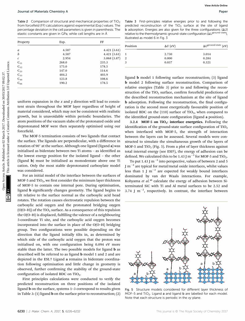
Table 2 Comparison of structural and mechanical properties of TiO2
from forcefield (FF) calculations against experimental (Exp.) values. Thepercentage deviation in the cell parameters is given in parenthesis. Theelastic constants are given in GPa, while cell lengths are in A
Property Exp. FF
a 4.587 4.421 (3.61)b 4.587 4.421 (3.61)c 2.954 3.068 (3.87)C11 268.0 235.3C12 175.0 178.5C23 147.0 114.6C33 484.2 403.9C44 123.8 108.6C66 190.2 178.5
Table 3 First-principles relative energies prior to and following thepredicted reconstruction of the TiO2 surface at the site of ligandb adsorption. Energies are also given for the three configurations (DU)relative to the thermodynamic ground-state configuration (DUground-state),illustrated as model 6 in Fig. 3
Position DU (eV) DUground-state (eV)
1 2.730 3.0142 0.000 0.2843 0.037 0.321
Fig. 5 Structure models considered for different layer thickness ofMOF-5 and TiO2. Ligand a and ligand b are labelled for each model.
Journal of Materials Chemistry A Paper
Ope
n A
cces
s A
rtic
le. P
ublis
hed
on 0
2 M
arch
201
7. D
ownl
oade
d on
30/
03/2
017
09:0
2:37
. T
his
artic
le is
lice
nsed
und
er a
Cre
ativ
e C
omm
ons
Attr
ibut
ion
3.0
Unp
orte
d L
icen
ce.
View Article Online
uniform expansion in the x and y direction will lead to consis-tent strain throughout the MOF layer regardless of height ofmaterial considered, which may not be consistent with realisticgrowth, but is unavoidable within periodic boundaries. Theatom positions of the vacuum slabs of the protonated oxide anddeprotonated MOF were then separately optimised using ourforceeld.
The MOF-5 termination consists of two ligands that contactthe surface. The ligands are perpendicular, with a difference inrotation of 90� at the surface. Although one ligand (ligand a) wasinitialised as bidentate between two Ti atoms – as identied asthe lowest energy position for the isolated ligand – the other(ligand b) must be initialised as monodentate above one Tication. Only the most stable deprotonated carboxylate modelwas considered.
For an initial model of the interface between the surfaces ofMOF-5 and TiO2, we rst consider the minimum layer thicknessof MOF-5 to contain one internal pore. During optimisation,ligand b signicantly changes geometry. The ligand begins totilt relative to the surface normal as the carboxylic acid headrotates. The rotation causes electrostatic repulsion between thecarboxylic acid oxygen and the protonated bridging oxygen(O(O–H)) of the TiO2 surface. As a consequence of this repulsionthe O(O–H) is displaced, fullling the valence of a neighbouring5-coordinate Ti site, and the carboxylic acid oxygen becomesincorporated into the surface in place of the O(O–H) bridginggroup. Two congurations were possible depending on thedirection that the ligand initially tilts in, as determined bywhich side of the carboxylic acid oxygen that the proton wasinitialised on, with one conguration being 0.094 eV morestable than the latter. The two possible models for ligand b asdescribed will be referred to as ligand b model 1 and 2 and aredepicted in the ESI.† Ligand a remains in bidentate coordina-tion following optimisation and little change in geometry isobserved, further conrming the stability of the ground-stateconguration of isolated BDC on TiO2.
First principles calculations were conducted to verify thepredicted reconstruction on three positions of the isolatedligand b on the surface, systems 1–3 correspond to results givenin Table 3: (1) ligand b on the surface prior to reconstruction; (2)
6230 | J. Mater. Chem. A, 2017, 5, 6226–6232
ligand b model 1 following surface reconstruction; (3) ligandb model 2 following surface reconstruction. Comparison ofrelative energies (Table 3) prior to and following the recon-struction of the TiO2 surface, conrm forceeld predictions ofthe described reconstruction mechanism at the site of ligandb adsorption. Following the reconstruction, the nal congu-ration is the second most energetically favourable position ofisolated BDC on the (110) surface of TiO2, when compared tothe identied ground-state conguration (ligand a position).
3.2.4 MOF-5 on TiO2: interface energetics. Following theidentication of the ground-state surface conguration of TiO2
when interfaced with MOF-5, the strength of interactionbetween the layers can be assessed. Several models were con-structed to simulate the simultaneous growth of the layers ofMOF-5 and TiO2 (Fig. 5). From a plot of layer thickness againsttotal internal energy (see ESI†), the energy of adhesion can bedened. We calculated this to be 1.43 J m�2 for MOF-5 and TiO2.
To put 1.43 J m�2 into perspective, values of between 2 and 5J m�2 are typical for metal/metal oxide interfaces, whilst valuesless than 1 J m�2 are expected for weakly bound interfacesdominated by van der Waals interactions. For example,Kohyama et al.49 calculate the energy of adhesion between Si-terminated SiC with Ti and Al metal surfaces to be 2.52 and3.74 J m�2, respectively. In contrast, the interface between
Note that each structure is periodic in the xy plane.
This journal is © The Royal Society of Chemistry 2017

Fig. 6 The (110) surface of TiO2 with highlighted oxygen sites whereproton migration from ligand a (green) and ligand b (purple) costs<0.1 eV as predicted by forcefield calculations. TiO4 polyhedra arehighlighted if ligand a (green) or ligand b (purple) remain bonding tothe Ti sites following optimisation. At the site of ligand b, an oxygenatom is highlighted (yellow), which belongs to carboxylate group ofligand b and has become incorporated into the surface followingreconstruction. Ligand orientation (white line) is given for both liganda and b. The full structure of the MOF has been removed for clarity.
Paper Journal of Materials Chemistry A
Ope
n A
cces
s A
rtic
le. P
ublis
hed
on 0
2 M
arch
201
7. D
ownl
oade
d on
30/
03/2
017
09:0
2:37
. T
his
artic
le is
lice
nsed
und
er a
Cre
ativ
e C
omm
ons
Attr
ibut
ion
3.0
Unp
orte
d L
icen
ce.
View Article Online
multi-layered graphene and SiO2 has an energy of adhesion of0.44 J m�2.50 The value we report for a MOF/oxide interfacetherefore suggests a reasonably strong chemical binding.
3.2.5 MOF-5 on TiO2: proton distribution. To further vali-date the identied ground-state congurations of the inter-facing surfaces, the possibility of proton migration acrossneighbouring oxide sites was considered for the model ofinterfacing MOF-5 and TiO2. An extensive analysis of differentproton positions was conducted by migrating the protons alongneighbouring oxide bridges of the TiO2 surfaces and comparingrelative energies. Owing to the expense of the size of the systemsconsidered, relative energies were calculated with the para-meterised forceeld, which can reproduce the binding energy ofthe proton to the surface as previously predicted by rstprinciples calculations. The movement of the protons fromligand a and b were considered separately for two differentstructure models with conguration descriptions and relativeenergies reported in the ESI.†
We calculate for both ligand a and b that the lowest energypositions of the proton (following deprotonation of the BDCligands), is to remain on a neighbouring oxide site. Fig. 6highlights the oxide positions surrounding ligand a andb where proton movement from the identied ground-statecongurations costs <0.1 eV. Interestingly, at the site of ligandb a further reconstruction of the surface is observed whensubstituting in a neighbouring site as highlighted (Fig. 6),resulting in the newly protonated oxygen being displaced off-site and tilt of the ligand changing as it rotates into the newposition at the surface in its place. The thickness of the MOF
This journal is © The Royal Society of Chemistry 2017
layer (as studied by considering the difference in calculatedenergies for structures 1 and 2) was found not to affect thebinding mechanism of MOF-5 on the surface of TiO2 (see ESI†).The same ground-state conguration is maintained for all layerthicknesses considered in this study.
4 Conclusions
A number of viable metal–organic framework/inorganicsubstrate combinations have been identied that could beused for epitaxial thin-lm growth. We have focused on theprototype case of the (011) surface of MOF-5 on the (110) surfaceof rutile TiO2, including the initial contact of the ligands, fol-lowed by the structure and thermodynamics of complete lms.Ideal growth with clean termination of surfaces were consideredfor this initial analysis of the thermodynamics associated withthe growth of MOFs on oxide surfaces. We nd that followingdeprotonation of the BDC ligand, it is thermodynamicallyfavourable for the TiO2 surface to reconstruct, resulting in theincorporation of a ligand into the surface. The energy of adhe-sion between MOF-5 and TiO2 surfaces is calculated to be 1.43 Jm�2, which reects the signicant chemical interaction at thehybrid heterointerface.
5 Data access statement
The VMOF forceeld is available as a library le for GULP fromhttps://github.com/WMD-group/VMOF. The interface structuremodels and program input/output les are available fromhttps://github.com/WMD-group/MOF-Epitaxy and https://researchdata.ands.org.au.
Acknowledgements
J. K. B. is funded by the EPSRC (grant no. EP/G03768X/1). J. D. G.thanks the Australian Research Council for funding under theDiscovery Programme, as well as the Pawsey SupercomputingCentre and NCI for the provision of computing resources. A. W.acknowledges support from the Royal Society UniversityResearch Fellowship scheme. K. L. S. is funded under ERCStarting Grant 277757 and K. T. B. is funded under EPSRC grantno. EP/M009580/1. The work beneted from the high perfor-mance computing facility at the University of Bath. Access to theARCHER supercomputer was facilitated through membershipof the HPC Materials Chemistry Consortium (EP/L000202).
References
1 O. Shekhah, H. Wang, D. Zacher, R. A. Fischer and C. Woll,Angew. Chem., Int. Ed., 2009, 48, 5038–5041.
2 L. K. Cadman, J. K. Bristow, N. E. Stubbs, D. Tiana,M. F. Mahon, A. Walsh and A. D. Burrows, Dalton Trans.,2016, 45, 4316–4326.
3 N. Stock and S. Biswas, Chem. Rev., 2011, 112, 933–969.4 D. Zacher, O. Shekhah, C. Woll and R. A. Fischer, Chem. Soc.Rev., 2009, 38, 1418–1429.
5 O. Shekhah, Materials, 2010, 3, 1302–1315.
J. Mater. Chem. A, 2017, 5, 6226–6232 | 6231

Journal of Materials Chemistry A Paper
Ope
n A
cces
s A
rtic
le. P
ublis
hed
on 0
2 M
arch
201
7. D
ownl
oade
d on
30/
03/2
017
09:0
2:37
. T
his
artic
le is
lice
nsed
und
er a
Cre
ativ
e C
omm
ons
Attr
ibut
ion
3.0
Unp
orte
d L
icen
ce.
View Article Online
6 D. Zacher, R. Schmid, C. Woll and R. A. Fischer, Angew.Chem., Int. Ed., 2011, 50, 176–199.
7 S. Hermes, F. Schroder, R. Chelmowski, C. Woll andR. A. Fischer, J. Am. Chem. Soc., 2005, 127, 13744–13745.
8 B. Liu, M. Ma, D. Zacher, A. Betard, K. Yusenko, N. Metzler-Nolte, C. Woll and R. A. Fischer, J. Am. Chem. Soc., 2011, 133,1734–1737.
9 E. Biemmi, C. Scherb and T. Bein, J. Am. Chem. Soc., 2007,129, 8054–8055.
10 C. H. Hendon and A. Walsh, Chem. Sci., 2015, 6, 3674–3683.11 R. Ameloot, L. Stappers, J. Fransaer, L. Alaerts, B. F. Sels and
D. E. De Vos, Chem. Mater., 2009, 21, 2580–2582.12 Y. Yoo and H.-K. Jeong, Cryst. Growth Des., 2010, 10, 1283–
1288.13 M. Tu and R. A. Fischer, J. Mater. Chem. A, 2014, 2, 2018–
2022.14 L. D. Salmi, M. J. Heikkila, E. Puukilainen, T. Sajavaara,
D. Grosso and M. Ritala, Microporous Mesoporous Mater.,2013, 182, 147–154.
15 I. Stassen, M. Styles, G. Grenci, H. Van Gorp,W. Vanderlinden, S. De Feyter, P. Falcaro, D. De Vos,P. Vereecken and R. Ameloot, Nat. Mater., 2015, 15, 304–310.
16 M. Shoaee, J. R. Agger, M. W. Anderson and M. P. Atteld,CrystEngComm, 2008, 10, 646–648.
17 S. Amirjalayer, M. Tapolsky and R. Schmid, J. Phys. Chem.Lett., 2014, 5, 3206–3210.
18 J. K. Bristow, K. L. Svane, D. Tiana, J. M. Skelton, J. D. Galeand A. Walsh, J. Phys. Chem. C, 2016, 120, 9276–9281.
19 K. T. Butler, Y. Kumagai, F. Oba and A. Walsh, J. Mater.Chem. C, 2016, 4, 1149–1158.
20 S. R. Bahn and K.W. Jacobsen, Comput. Sci. Eng., 2002, 4, 56–66.
21 A. Zur and T. McGill, J. Appl. Phys., 1984, 55, 378–386.22 A. Zur, T. McGill and M.-A. Nicolet, J. Appl. Phys., 1985, 57,
600–603.23 J. VandeVondele, M. Krack, F. Mohamed, M. Parrinello,
T. Chassaing and J. Hutter, Comput. Phys. Commun., 2005,167, 103–128.
24 J. P. Perdew, A. Ruzsinszky, G. I. Csonka, O. A. Vydrov,G. E. Scuseria, L. A. Constantin, X. Zhou and K. Burke,Phys. Rev. Lett., 2008, 100, 136406.
25 S. Grimme, J. Antony, S. Ehrlich and H. Krieg, J. Chem. Phys.,2010, 132, 154104.
26 M. Krack, Theor. Chem. Acc., 2005, 114, 145–152.27 K. A. Peterson and T. H. Dunning Jr, J. Chem. Phys., 2002,
117, 10548–10560.
6232 | J. Mater. Chem. A, 2017, 5, 6226–6232
28 T. H. Dunning Jr, J. Chem. Phys., 1970, 53, 2823–2833.29 J. D. Gale, J. Chem. Soc., Faraday Trans., 1997, 93, 629–637.30 J. D. Gale and A. L. Rohl, Mol. Simul., 2003, 29, 291–341.31 J. K. Bristow, J. M. Skelton, K. L. Svane, A. Walsh and
J. D. Gale, Phys. Chem. Chem. Phys., 2016, 18, 29316–29329.32 J. K. Bristow, D. Tiana and A. Walsh, J. Chem. Theory
Comput., 2014, 10, 4644–4652.33 N. L. Allinger, Y. H. Yuh and J. H. Lii, J. Am. Chem. Soc., 1989,
111, 8551–8566.34 N. L. Allinger, F. Li and L. Yan, J. Comput. Chem., 1990, 11,
848–867.35 B. R. Brooks, C. L. Brooks, A. D. MacKerell, L. Nilsson,
R. J. Petrella, B. Roux, Y. Won, G. Archontis, C. Bartels andS. Boresch, J. Comput. Chem., 2009, 30, 1545–1614.
36 J. Gasteiger and M. Marsili, Tetrahedron, 1980, 36, 3219–3228.
37 J. Gasteiger andM.Marsili, Tetrahedron Lett., 1978, 19, 3181–3184.
38 S. Hermes, D. Zacher, A. Baunemann, C. Woll andR. A. Fischer, Chem. Mater., 2007, 19, 2168–2173.
39 N. Negishi, K. Takeuchi and T. Ibusuki, J. Mater. Sci., 1998,33, 5789–5794.
40 D. O. Scanlon, C. W. Dunnill, J. Buckeridge, S. A. Shevlin,A. J. Logsdail, S. M. Woodley, C. R. A. Catlow, M. J. Powell,R. G. Palgrave, I. P. Parkin, et al., Nat. Mater., 2013, 12,798–801.
41 J. Buckeridge, K. T. Butler, C. R. A. Catlow, A. J. Logsdail,D. O. Scanlon, S. A. Shevlin, S. M. Woodley, A. A. Sokol andA. Walsh, Chem. Mater., 2015, 27, 3844–3851.
42 A. Tekiel, J. S. Prauzner-Bechcicki, S. Godlewski, J. Budziochand M. Szymonski, J. Phys. Chem. C, 2008, 112, 12606–12609.
43 S. S. Kaye, A. Dailly, O. M. Yaghi and J. R. Long, J. Am. Chem.Soc., 2007, 129, 14176–14177.
44 S. Fleming and A. Rohl, Z. Kristallogr., 2005, 220, 580–584.45 C. Zhang and P. J. Lindan, J. Chem. Phys., 2003, 118, 4620–
4630.46 J.-M. Pan, B. Maschhoff, U. Diebold and T. Madey, J. Vac. Sci.
Technol., A, 1992, 10, 2470–2476.47 K. Onda, B. Li, J. Zhao, K. D. Jordan, J. Yang and H. Petek,
Science, 2005, 308, 1154–1158.48 B. J. Morgan and G. W. Watson, J. Phys. Chem. C, 2009, 113,
7322–7328.49 M. Kohyama and J. Hoekstra, Phys. Rev. B: Condens. Matter
Mater. Phys., 2000, 61, 2672.50 S. P. Koenig, N. G. Boddeti, M. L. Dunn and J. S. Bunch, Nat.
Nanotechnol., 2011, 6, 543–546.
This journal is © The Royal Society of Chemistry 2017