
Journal of Materials Chemistry A - CAS€¦ · The corresponding NCH/G/NF samples synthesized in a...
9
Controllable synthesis of 3D binary nickel–cobalt hydroxide/graphene/nickel foam as a binder-free electrode for high-performance supercapacitors† Yang Bai, Weiqi Wang, Ranran Wang, Jing Sun * and Lian Gao Binder-free electrodes based on 3D porous nickel–cobalt binary hydroxides (NCH)/graphene (G) composites on nickel foam (NF) for supercapacitors are fabricated via a chemical vapor deposition (CVD) process combined with an electrochemical deposition (ED) method. High quality graphene grown on NF makes the surface more suitable for deposition of 3D porous NCH and simultaneously enhances the electrode conductivity. The 3D structure can improve the electron transport ability and increase the contact of the active sites with electrolyte. The morphology and electrochemical performance of NCH/ G/NF electrodes can be readily manipulated by adjusting the deposition current density and the Ni–Co ratio of the deposition solution. High capacitance with enhanced stability and rate capability is achieved and is attributed to the synergetic effect of the above factors. Specifically, at the deposition current density of 0.625 mA cm 2 and Ni–Co ratio of 1 : 1, the NCH11/G/NF electrode exhibits a maximum specific capacitance of 1410 F g 1 at2Ag 1 . When the current density increases to 4 A g 1 , the capacitance is still 1328 F g 1 with a high capacitance retention of 94.2%. After 2500 cycles, the capacitance retention is 92.1%, which is higher than that of a common slurry-coated electrode. To research its practical applications, an asymmetric supercapacitor was fabricated with a NCH11/G/NF electrode as the positive electrode and activated carbon as the negative electrode. The asymmetric device exhibits a prominent energy density of 33.75 W h kg 1 at a power density of 750 W kg 1 . The binder-free electrode with superior performance has been proven to be very promising for energy storage. 1. Introduction In recent years, renewable and clean energies such as solar, wind, and wave energy have been quickly exploited to resolve the increasingly serious energy crisis and environmental issues. At the same time, efficient energy storage devices with high energy and power densities are urgently demanded. Super- capacitors (SCs), also known as electrochemical capacitors, have attracted considerable attention due to their ultra-high power density, long cycling stability, wide operative tempera- ture range, and improved safety. 1,2 However, the energy densi- ties of SCs are much lower than those of batteries, which restrict their wide application and need to be improved. The perfor- mance of SCs is primarily determined by the properties of the electrode materials. 3 In order to enhance the energy densities of SCs, electrode materials with high capacitance are required according to the formula of energy density (E) E ¼ CU 2 /2. Thus far, there are mainly three types of electrode materials for SCs: carbon materials, 4 transition metal oxides/hydroxides, 5–8 and conducting polymer materials. 9 Among them, carbon materials have a large specic surface area, excellent electrical conduc- tivity, and high power densities, while they exhibit low energy densities limited by their adsorption capacity. 10–12 Transition metal oxides/hydroxides possess unique redox properties and high theoretical specic capacitance values. Unfortunately, the key weakness of transition metal oxides/hydroxides is their poor electrical conductivities, 13 leading to low power densities. Consequently, the major challenge for SCs is to improve their energy densities and simultaneously retain their high power densities. Among various transition metal oxides/hydroxides investi- gated for SCs, nickel oxides/hydroxides and cobalt oxides/ hydroxides with high theoretical capacitance and specic shapes and structures have been extensively researched. The fabrication of binary Ni–Co hydroxides/oxides with a hierar- chical architecture is both feasible and promising due to the nearly identical physical and chemical properties and the miscible ions in aqueous solution of nickel and cobalt. 14 In addition, the binary system not only inherits the merits of the individual components, but also yields much higher electro- chemical performance. The atomic substitution will increase The State Key Lab of High Performance Ceramics and Superne Microstructure, Shanghai Institute of Ceramics, Chinese Academy of Sciences, 1295 Dingxi Road, Shanghai 200050, P.R. China. E-mail: [email protected]; [email protected]. cn; Fax: +86-21-52413122; Tel: +86-21-52414301 † Electronic supplementary information (ESI) available: See DOI: 10.1039/c5ta01804h Cite this: J. Mater. Chem. A, 2015, 3, 12530 Received 11th March 2015 Accepted 6th May 2015 DOI: 10.1039/c5ta01804h www.rsc.org/MaterialsA 12530 | J. Mater. Chem. A, 2015, 3, 12530–12538 This journal is © The Royal Society of Chemistry 2015 Journal of Materials Chemistry A PAPER
-
Upload
nguyentuyen -
Category
Documents
-
view
214 -
download
1
Transcript of Journal of Materials Chemistry A - CAS€¦ · The corresponding NCH/G/NF samples synthesized in a...

Journal ofMaterials Chemistry A
PAPER
Controllable syn
The State Key Lab of High Performance
Shanghai Institute of Ceramics, Chinese A
Shanghai 200050, P.R. China. E-mail: jing
cn; Fax: +86-21-52413122; Tel: +86-21-5241
† Electronic supplementary informa10.1039/c5ta01804h
Cite this: J. Mater. Chem. A, 2015, 3,12530
Received 11th March 2015Accepted 6th May 2015
DOI: 10.1039/c5ta01804h
www.rsc.org/MaterialsA
12530 | J. Mater. Chem. A, 2015, 3, 125
thesis of 3D binary nickel–cobalthydroxide/graphene/nickel foam as a binder-freeelectrode for high-performance supercapacitors†
Yang Bai, Weiqi Wang, Ranran Wang, Jing Sun* and Lian Gao
Binder-free electrodes based on 3D porous nickel–cobalt binary hydroxides (NCH)/graphene (G)
composites on nickel foam (NF) for supercapacitors are fabricated via a chemical vapor deposition (CVD)
process combined with an electrochemical deposition (ED) method. High quality graphene grown on NF
makes the surface more suitable for deposition of 3D porous NCH and simultaneously enhances the
electrode conductivity. The 3D structure can improve the electron transport ability and increase the
contact of the active sites with electrolyte. The morphology and electrochemical performance of NCH/
G/NF electrodes can be readily manipulated by adjusting the deposition current density and the Ni–Co
ratio of the deposition solution. High capacitance with enhanced stability and rate capability is achieved
and is attributed to the synergetic effect of the above factors. Specifically, at the deposition current
density of 0.625 mA cm�2 and Ni–Co ratio of 1 : 1, the NCH11/G/NF electrode exhibits a maximum
specific capacitance of 1410 F g�1 at 2 A g�1. When the current density increases to 4 A g�1, the
capacitance is still 1328 F g�1 with a high capacitance retention of 94.2%. After 2500 cycles, the
capacitance retention is 92.1%, which is higher than that of a common slurry-coated electrode. To
research its practical applications, an asymmetric supercapacitor was fabricated with a NCH11/G/NF
electrode as the positive electrode and activated carbon as the negative electrode. The asymmetric
device exhibits a prominent energy density of 33.75 W h kg�1 at a power density of 750 W kg�1. The
binder-free electrode with superior performance has been proven to be very promising for energy storage.
1. Introduction
In recent years, renewable and clean energies such as solar,wind, and wave energy have been quickly exploited to resolvethe increasingly serious energy crisis and environmental issues.At the same time, efficient energy storage devices with highenergy and power densities are urgently demanded. Super-capacitors (SCs), also known as electrochemical capacitors,have attracted considerable attention due to their ultra-highpower density, long cycling stability, wide operative tempera-ture range, and improved safety.1,2 However, the energy densi-ties of SCs are much lower than those of batteries, which restricttheir wide application and need to be improved. The perfor-mance of SCs is primarily determined by the properties of theelectrode materials.3 In order to enhance the energy densities ofSCs, electrode materials with high capacitance are requiredaccording to the formula of energy density (E) E ¼ CU2/2. Thus
Ceramics and Superne Microstructure,
cademy of Sciences, 1295 Dingxi Road,
[email protected]; [email protected].
4301
tion (ESI) available: See DOI:
30–12538
far, there are mainly three types of electrode materials for SCs:carbon materials,4 transition metal oxides/hydroxides,5–8 andconducting polymer materials.9 Among them, carbon materialshave a large specic surface area, excellent electrical conduc-tivity, and high power densities, while they exhibit low energydensities limited by their adsorption capacity.10–12 Transitionmetal oxides/hydroxides possess unique redox properties andhigh theoretical specic capacitance values. Unfortunately, thekey weakness of transitionmetal oxides/hydroxides is their poorelectrical conductivities,13 leading to low power densities.Consequently, the major challenge for SCs is to improve theirenergy densities and simultaneously retain their high powerdensities.
Among various transition metal oxides/hydroxides investi-gated for SCs, nickel oxides/hydroxides and cobalt oxides/hydroxides with high theoretical capacitance and specicshapes and structures have been extensively researched. Thefabrication of binary Ni–Co hydroxides/oxides with a hierar-chical architecture is both feasible and promising due to thenearly identical physical and chemical properties and themiscible ions in aqueous solution of nickel and cobalt.14 Inaddition, the binary system not only inherits the merits of theindividual components, but also yields much higher electro-chemical performance. The atomic substitution will increase
This journal is © The Royal Society of Chemistry 2015
Paper Journal of Materials Chemistry A
electrical conductivity and effectively enhance the active sitedensity and roughness of the nal binary product.15,16 Liu et al.synthesized a porous NiCo2O4 heterostructure array with a highcapacitance of 1089 F g�1.17 Hu et al. reported a sol–gelsynthesis route of nickel–cobalt oxides, showing a high speciccapacitance of 1539 F g�1 at 1 A g�1.13 However, the cyclingstability was poor, and the electrode encountered great capacityloss. This phenomenon was probably due to the weak electrontransport ability, which was caused by the compact structureand the existence of binder. Recently, many efforts18–20 havebeen concentrated on the composites of carbon materials andtransition metal oxides/hydroxides to cover the shortage oftransition metal oxide/hydroxide materials.
Graphene (G) is a carbon material with a two-dimensionalstructure, large surface, and integrated conductive network thatis suitable for loading other materials.21 Thus far, reducedgraphene oxide (RGO) is commonly used as the matrix forelectrode materials due to its high production. With the help ofRGO, the capacitance of electrode materials is enhanced.22,23
However, RGO-based composites show insufficient cyclingstability due to the negative effects of the residual oxygen-con-taining functional groups in RGO. The properties of RGOmainly depend on the synthesis process of RGO, which alsoaffects the stability. Furthermore, an even greater challenge isthe conict between the mass loading of active materials pervolume and its utilization efficiency. RGO-based electrodes arecommonly binder-enriched by a slurry-coating method. Thebinder transforms a large portion of active material surface into“dead surface” and decreases the electrical conductivity ofelectrode materials.24 Thus, there is a demand for high qualitygraphene and binder-free electrodes, with the goal of obtaininghigher performance of electrodes for SCs.
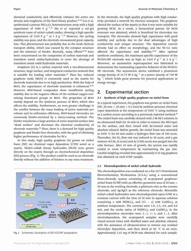
In this study, high quality graphene (G) grown on nickelfoam (NF) via chemical vapor deposition (CVD) acted as amatrix. Nickel–cobalt binary hydroxides (NCH) were growndirectly on the matrix through an electrochemical deposition(ED) process (Fig. 1). The product could be used as an electrodedirectly without the addition of binders or any extra treatment.
Fig. 1 Schematic illustration of NCH/G/NF preparation.
This journal is © The Royal Society of Chemistry 2015
In the electrode, the high quality graphene with high conduc-tivity provided a network for electron transport. The graphenealtered the surface of the matrix so that it was more suitable forgrowing NCH. As a result, a hierarchical porous 3D NCHstructure was obtained, which is benecial for electrolyte iontransport. The electrodes showed high capacitance with goodstability and cyclicity due to the dual advantages of highconductivity and unique structure. The deposition currentdensity had an effect on morphology, and the Ni–Co ratioaffected the capacitance and stability.13,25 Aer optimalsynthesis conditions, the maximum specic capacitance of theNCH/G/NF electrode was as high as 1410 F g�1 at 2 A g�1.Moreover, an asymmetric supercapacitor was fabricated todemonstrate the outstanding capacitive behavior of the NCH/G/NF electrode. The asymmetric device exhibited a prominentenergy density of 33.75 W h kg�1 at a power density of 750 Wkg�1, which holds great promise for practical applications inenergy storage.
2. Experimental section2.1 Synthesis of high quality graphene on nickel foam
In a typical experiment, the graphene was grown on nickel foam(NF, 20 mm � 20 mm � 0.5 mm) by ambient pressure chemicalvapor deposition at the temperature of 1050 �C using methaneas a carbon source according to a previously reported method.26
The nickel foam was carefully cleaned with 2 M HCl solution inan ultrasound bath for 30 min in order to remove the NiO layeron the surface, and then rinsed with de-ionized water andabsolute ethanol. Before growth, the nickel foam was annealedat 1050 �C for 60 min under a hydrogen ow rate of 100 sccm.Thereaer, the H2 ow rate was reduced to 40 sccm, and a gasmixture of CH4 (6 sccm) and Ar (1500 sccm) was purged into thetube furnace. Aer 10 min of growth, the system was rapidlycooled to room temperature by maintaining the gas rate.Careful weighing revealed that approximately 0.45 mg graphenewas obtained on each G/NF sample.
2.2 Electrodeposition of nickel–cobalt hydroxide
The electrodeposition was conducted on a Par 2273 PotentiostatElectrochemistry Workstation (U.S.A.) using a conventionalthree-electrode system consisting of as-prepared graphene/nickel foam (G/NF) with an effective geometric area of 20 mm �20 mm as the working electrode, a platinum wire as the counterelectrode, and Ag/AgCl as the reference electrode. Bimetallicnickel–cobalt hydroxides were electrodeposited upon G/NF at aconstant current with the time of 30 min in aqueous solutioncontaining x mM Ni(NO3)2 and (15 � x) mM Co(NO3)2 atambient temperature. The currents were 1.0, 2.5, 4.0, and 8.0mA, and the molar ratios of Ni(NO3)2 and Co(NO3)2 in theelectrodeposition electrolyte were 2 : 1, 1 : 1, and 1 : 2. Aerelectrodeposition, the as-prepared samples were carefullyrinsed several times with distilled water and absolute ethanol,with the assistance of ultrasonication to remove any residualelectrolyte deposition, and then dried at 60 �C in an oven.Approximately 2.45 mg of NCH was obtained for each sample.
J. Mater. Chem. A, 2015, 3, 12530–12538 | 12531

Journal of Materials Chemistry A Paper
The corresponding NCH/G/NF samples synthesized in a seriesof electrodeposition electrolytes with different Ni–Co molarratios were denoted as NCH21/G/NF (2 : 1), NCH11/G/NF (1 : 1),and NCH12/G/NF (1 : 2), respectively.
2.3 Fabrication of an asymmetric supercapacitor
An asymmetric supercapacitor was fabricated based on theNCH11/G/NF electrode as the positive electrode, the activatedcarbon (AC) electrode as the negative electrode, and poly-propylene (PP) ber as the separator. The negative electrode wasprepared as follows: AC, carbon black, and polyvinylideneuoride (PVDF) binder in a weight ratio of 80 : 10 : 10 weremixed in ethanol and then pasted onto a nickel foam currentcollector (20 mm� 20 mm). The mass ratio of positive electrodeto negative electrode was decided according to the well-knowncharge balance theory (q+ ¼ q�).5 In the relationship, the chargestored by each electrode usually depends on the speciccapacitance (C), the potential window (Dv), and the mass ofactive material (m), as shown in eqn (1):
q ¼ C � Dv � m (1)
In order to obtain q+ ¼ q�, the mass balancing will beexpressed as eqn (2):
mþ
m� ¼ C� � Dv�
Cþ � Dvþ(2)
Based on the specic capacitances of the NCH11/G/NFelectrode and AC electrode, the optimal mass ratio between thetwo electrodes was calculated to be approximately m�/m+ ¼ 3.2in the asymmetric supercapacitor.
Fig. 2 Typical SEM images of pristine (a) NF, (b) NCH/NF, (c) G/NF, and(d) NCH/G/NF.
2.4 Characterization
Powder X-ray diffraction (XRD, Rigaku D/Max 2200 PC, Cu Ka)was conducted to characterize the crystalline structure. Ramanspectroscopy was recorded on a DXR Raman microscope withan excitation length of 532 nm. X-ray photoelectron spectros-copy (XPS) analysis was conducted using a twin anode gun, MgKa (1253.6 eV) (Microlab 310F Scanning Auger Microprobe, VGScientic Ltd). Themorphologies and structures of the productswere analyzed by eld-emission scanning electron microscopy(FE-SEM, S4800) with energy dispersive spectrometry (EDS,Oxford, INCAx-act) and transmission electron microscopy(TEM, JEOL JEM-2100F). The elemental composition of Ni andCo in the prepared samples was analyzed employing atomicabsorption spectrophotometry (AAS, PerkinElmer 5000).
The electrochemical properties of the materials were char-acterized using a three-electrode system in 2 M KOH aqueoussolution at room temperature. The as-prepared NCH/G/NF wasused as the working electrode. Each working electrode had thesame area of 20 mm � 20 mm with the weight of the total activematerials approximately 2.9 mg (2.45 mg NCH and 0.45 mggraphene). Platinum wire was used as the counter electrode andHg/HgO as the reference electrode. The electrochemicalimpedance spectrum (EIS) was tested by applying an AC voltage
12532 | J. Mater. Chem. A, 2015, 3, 12530–12538
with 5 mV amplitude in a frequency range from 0.01 Hz to 100kHz using a 1260-1470E-1455A electrochemical workstation(Solartron, U.S.A). The cyclic voltammetry (CV) at �0.1 to 0.6 Vwas performed on a CHI660D workstation (CH Instruments,Inc.). The galvanostatic charge and discharge tests were carriedout in the potential range of 0–0.5 V on a LAND CT2001 batterytester. The specic capacitances Cs were calculated from thegalvanostatic discharge curves using the equation:27,28
Cs ¼ it
mDv(3)
where i, t, Dv, andm are the constant current (A), discharge time(s), potential drop during discharge (V), and mass of activematerials (g), respectively. The electrochemical properties of theasymmetric supercapacitor were also investigated in 2 M KOHelectrolyte but in a two-electrode cell. All of the electrochemicalexperiments were carried out on a CHI660D workstation andLAND CT2001 battery tester at room temperature. The energydensity (E) and power density (P) of the asymmetric super-capacitor are estimated as follows:29
E ¼ 1
2CsðDvÞ2 (4)
P ¼ E
t(5)
where Cs (F g�1) is the specic capacitance, t (s) is the dischargetime (s), and Dv (V) is the potential change during the dischargeprocess.
3. Results and discussion3.1 Synthesis and structural analysis
The XRD pattern of NCH powders that were scraped from theNCH/G/NF electrodes are illustrated in Fig. S1.† The patternconrms the existence of Ni–Co binary hydroxides. The typicalSEM image of pristine NF, as shown in Fig. 2a, presents a highly
This journal is © The Royal Society of Chemistry 2015

Fig. 3 Raman spectroscopy of pristine NF, G/NF, and NCH/G/NF.
Paper Journal of Materials Chemistry A
textured surface. A large number of nanosized pores can beobserved on the surface with some wrinkles. During the EDprocess, NCH is deposited on the pristine NF, and themorphology of the NCH is similar to the NF (Fig. 2b and S2†).The NCH sheets are tiny and closely packed, which will decreasethe liquid–solid interface area and the utilization of active sites.Consequently, the pristine NF is inappropriate to be used as amatrix for the growth of NCH. Fig. 2c shows the morphology ofgraphene grown on NF via the CVD process. Graphene withsome wrinkles is coated on the entire surface of NF, whichattens the surface. Aer the ED process, NCH slices are grownon graphene with a nest-like porous structure (Fig. 2d). The thinslices are uniformly distributed on the graphene with a largesurface area. In comparison with NCH on NF, the NCH slicesgrown on G/NF are bigger and curly, which hinders the aggre-gation between these slices. The different morphologies of NCHon different matrices demonstrate that the graphene has apositive effect on constructing the 3D porous structure. Thishybrid nanostructure ensures (i) improved electronic conduc-tivity due to high quality graphene and NF, (ii) enhanced ionicconductivity due to the porous network, (iii) high utilization ofactive sites on the enlarged surface area, and (iv) optimized iontransport property by avoiding the binder and conductive agent.
Further examination with XPS illustrates the detailed infor-mation regarding elements and oxidation states of the as-prepared NCH/G/NF electrodes (Fig. S3†). In the high-resolutionC1s spectra of NCH/G/NF (Fig. S3d†), the absorbance bandintensity of C–C is strong with little existence of oxygen-con-taining functional groups, demonstrating the high quality ofthe graphene. The broad peak of O 1s is centered at 532 eV,which is associated with bound hydroxide groups (OH�) andconrms the formation of Ni–Co binary hydroxides (Fig. S3e†).30
The Ni 2p and Co 2p spectra both show two spin–orbit doubletswith shakeup satellites peaks (Fig. S3f and S3g†), illustratingthat NCH is composed of Ni2+, Ni3+, Co2+, and Co3+.
In order to further demonstrate the quality of the grapheneand its stability, Raman spectra were obtained for differentsamples. The G band (approximately 1590 cm�1) is attributed tothe vibration of sp2-bonded carbon atoms, while the D band(approximately 1350 cm�1) arises from disorders or defects, andthe 2D band at approximately 2700 cm�1 originates from adouble-resonance process.31–34 As exhibited in Fig. 3, only G and2D bands can be observed in the G/NF and NCH/G/NF elec-trodes, which conrms the high structural quality of the defect-free graphene.35 Moreover, the integrated intensity ratio betweenthe G and 2D bands (IG/I2D) reveals that the graphene has fewlayers.36 During the ED process, the IG/I2D ratio retains a similarvalue. The results also demonstrate that high-quality graphene ismaintained during the ED process. Because the pure NF has nopeaks, the peaks at approximately 500 cm�1 are conrmed to beNCH. High quality graphene will signicantly improve theconductivity,37 and thus, high cycling stability is expected.
Fig. 4 SEM images of NCH/G/NF prepared at different ED currentdensities, (a) 0.25 mA cm�2, (b) 0.625 mA cm�2, (c) 1 mA cm�2, and (d)2 mA cm�2.
3.2 The effect of deposition current density
The morphology and microstructure of electrode materials,decided by the ED process, have a great effect on the
This journal is © The Royal Society of Chemistry 2015
electrochemical performance. Among all the synthesis condi-tions, the deposition current density has a large inuence on thegrowth process of NCH slices, which is discussed rstly. Fig. 4shows the morphologies of NCH/G/NF electrodes prepared atdifferent current densities. At a low current density of 0.25 mAcm�2, NCH particles with the size of 100–200 nm are formed(Fig. 4a). These particles contact each other tightly, showing thetrend to form sheets. The compact structure with a smallnumber of pores will decrease the active sites for redox reaction.When the current density increases to 0.625 mA cm�2, NCHgrows into thin sheets with a large size (Fig. 4b). Numerous poresare created between the neighboring nanosheets for ion trans-port. The loose and porous structure enlarges the surface area toincrease the active sites, and the thin sheets will also shorten theelectron transportation distance. Fig. 4c displays the NCH sheetsprepared at 1 mA cm�2, which are thicker and tightly assemble
J. Mater. Chem. A, 2015, 3, 12530–12538 | 12533
Journal of Materials Chemistry A Paper
together. At 2 mA cm�2, the structure of NCH becomes morecompact (Fig. 4d). These two compact textures will decrease thecontact area with the electrolyte and active sites for redox reac-tion. The probable reason for the formation of differentmorphologies is as follows. At low current density, the totalquantity of electric charge is small, which restricts the growth ofNCH due to the relatively low rate of reaction. When the currentdensity increases, the electrode can obtain more electrons andions to formNCH sheets. However, at high current density, moreNi and Co ions transform to NCH, and the structure becomecompact.
3.3 The effect of Ni–Co ratio in the deposition solution
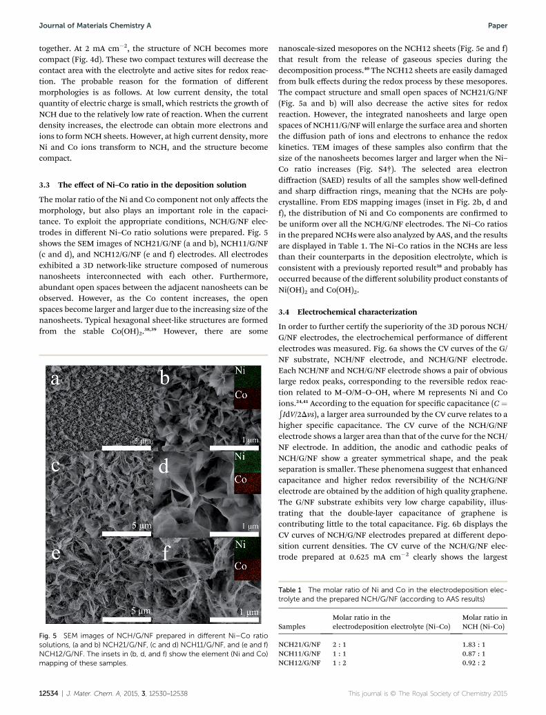
The molar ratio of the Ni and Co component not only affects themorphology, but also plays an important role in the capaci-tance. To exploit the appropriate conditions, NCH/G/NF elec-trodes in different Ni–Co ratio solutions were prepared. Fig. 5shows the SEM images of NCH21/G/NF (a and b), NCH11/G/NF(c and d), and NCH12/G/NF (e and f) electrodes. All electrodesexhibited a 3D network-like structure composed of numerousnanosheets interconnected with each other. Furthermore,abundant open spaces between the adjacent nanosheets can beobserved. However, as the Co content increases, the openspaces become larger and larger due to the increasing size of thenanosheets. Typical hexagonal sheet-like structures are formedfrom the stable Co(OH)2.38,39 However, there are some
Fig. 5 SEM images of NCH/G/NF prepared in different Ni–Co ratiosolutions, (a and b) NCH21/G/NF, (c and d) NCH11/G/NF, and (e and f)NCH12/G/NF. The insets in (b, d, and f) show the element (Ni and Co)mapping of these samples.
12534 | J. Mater. Chem. A, 2015, 3, 12530–12538
nanoscale-sized mesopores on the NCH12 sheets (Fig. 5e and f)that result from the release of gaseous species during thedecomposition process.40 The NCH12 sheets are easily damagedfrom bulk effects during the redox process by these mesopores.The compact structure and small open spaces of NCH21/G/NF(Fig. 5a and b) will also decrease the active sites for redoxreaction. However, the integrated nanosheets and large openspaces of NCH11/G/NF will enlarge the surface area and shortenthe diffusion path of ions and electrons to enhance the redoxkinetics. TEM images of these samples also conrm that thesize of the nanosheets becomes larger and larger when the Ni–Co ratio increases (Fig. S4†). The selected area electrondiffraction (SAED) results of all the samples show well-denedand sharp diffraction rings, meaning that the NCHs are poly-crystalline. From EDS mapping images (inset in Fig. 2b, d andf), the distribution of Ni and Co components are conrmed tobe uniform over all the NCH/G/NF electrodes. The Ni–Co ratiosin the prepared NCHs were also analyzed by AAS, and the resultsare displayed in Table 1. The Ni–Co ratios in the NCHs are lessthan their counterparts in the deposition electrolyte, which isconsistent with a previously reported result38 and probably hasoccurred because of the different solubility product constants ofNi(OH)2 and Co(OH)2.
3.4 Electrochemical characterization
In order to further certify the superiority of the 3D porous NCH/G/NF electrodes, the electrochemical performance of differentelectrodes was measured. Fig. 6a shows the CV curves of the G/NF substrate, NCH/NF electrode, and NCH/G/NF electrode.Each NCH/NF and NCH/G/NF electrode shows a pair of obviouslarge redox peaks, corresponding to the reversible redox reac-tion related to M–O/M–O–OH, where M represents Ni and Coions.24,41 According to the equation for specic capacitance (C ¼ÐIdV/2Dvs), a larger area surrounded by the CV curve relates to a
higher specic capacitance. The CV curve of the NCH/G/NFelectrode shows a larger area than that of the curve for the NCH/NF electrode. In addition, the anodic and cathodic peaks ofNCH/G/NF show a greater symmetrical shape, and the peakseparation is smaller. These phenomena suggest that enhancedcapacitance and higher redox reversibility of the NCH/G/NFelectrode are obtained by the addition of high quality graphene.The G/NF substrate exhibits very low charge capability, illus-trating that the double-layer capacitance of graphene iscontributing little to the total capacitance. Fig. 6b displays theCV curves of NCH/G/NF electrodes prepared at different depo-sition current densities. The CV curve of the NCH/G/NF elec-trode prepared at 0.625 mA cm�2 clearly shows the largest
Table 1 The molar ratio of Ni and Co in the electrodeposition elec-trolyte and the prepared NCH/G/NF (according to AAS results)
SamplesMolar ratio in theelectrodeposition electrolyte (Ni–Co)
Molar ratio inNCH (Ni–Co)
NCH21/G/NF 2 : 1 1.83 : 1NCH11/G/NF 1 : 1 0.87 : 1NCH12/G/NF 1 : 2 0.92 : 2
This journal is © The Royal Society of Chemistry 2015

Fig. 6 (a) CV curves of G/NF, NCH/NF, and NCH/G/NF electrodes at ascan rate of 5 mV s�1. (b) CV curves of NCH/G/NF electrodes preparedat different deposition current densities at a scan rate of 5 mV s�1. (c)CV curves of electrodes with different Ni–Co ratios at a scan rate of5 mV s�1.
Fig. 7 (a) Galvanostatic discharge curves at 2 A g�1 of NCH/G/NFelectrodes prepared at different deposition current densities. (b) Gal-vanostatic discharge curves at 2 A g�1 of electrodes with different Ni–Co ratios. (c) Galvanostatic discharge curves of electrodes withdifferent Ni–Co ratios at various discharge current densities. (d) Ratecapacitance of electrodes with different Ni–Co ratios with increasingcurrent densities. (e) Cyclic performance of electrodes with differentNi–Co ratios at 4 A g�1. (f) SEM image of the NCH11 electrode after acharging and discharging test of 2500 cycles.
Paper Journal of Materials Chemistry A
surrounding area, indicating the highest specic capacitance.The enhanced capacitance benets from increased active sitesdue to the 3D porous structure of the large nanosheets and openspaces. The most suitable current density is 0.625 mA cm�2,which is consistent with the SEM analysis. The effect of the Ni–Co ratio in the deposition solution is also discussed. As shownin Fig. 6c, all the CV curves of the samples at different ratiosshow typical pseudo-capacitive shapes with symmetric redoxpeaks, indicating that there is good redox reversibility. Thecurve of the NCH21/G/NF electrode shows a smaller area due tothe compact structure, which has less active sites. It has beenreported that the addition of Co will reduce the specic capac-itance,38 and therefore, the NCH12/G/NF electrode with a highCo content also shows a relatively low capacitance. Taking intoeffect the dual effects of porous structure and Ni–Co ratio, theNCH11/G/NF electrode shows an enhanced capacitancecompared with the other two electrodes.
A series of charge and discharge measurements was con-ducted on different electrodes at various currents. Fig. 7aexhibits the discharge curves of NCH/G/NF electrodes preparedat different deposition current densities. Based on eqn (3) forcalculating specic capacitance, a longer discharge timedenotes a higher capacitance. The NCH/G/NF electrodeprepared at 0.625 mA cm�2 shows the longest discharge time,which is in accordance with the CV results. For electrodes withdifferent Ni–Co ratios (Fig. 7b), all the electrodes displayedtypical pseudo-capacitive behavior with highly nonlineardischarge curves. All the curves show the obvious dischargevoltage plateaus, which match well with the reduction peaksobserved in the CV curves (Fig. 6c). Fig. 7c shows dischargecurves of electrodes with different Ni–Co ratios at variouscurrent densities of 2, 4, 8, and 20 A g�1. The NCH11/G/NFelectrode exhibits the highest capacitance performance.Calculations determined the specic capacitances of the
This journal is © The Royal Society of Chemistry 2015
NCH21/G/NF, NCH11/G/NF, and NCH12/G/NF electrodes,which are 1050, 1410, and 1210 F g�1 at 2 A g�1, respectively.Even at the high current density of 20 A g�1, the speciccapacitance of the NCH11/G/NF electrode is still over 1000 Fg�1. To further analyze the rate capacity, the capacitances atvarious current densities are shown in Fig. 7d. At 4 A g�1, thecapacitances are 984, 1328, and 1056 F g�1 for the NCH21/G/NF,NCH11/G/NF, and NCH12/G/NF electrodes with high rateretentions of 93.5%, 94.6%, and 87.7%, respectively. At 20 A g�1,the capacitance loss of the NCH11/G/NF electrode is as low as25.9%, which is still lower than those of 31.6% and 27.1% forthe NCH21/G/NF and NCH12/G/NF electrodes, respectively. Thecompact structure and low Co ratio of NCH21 and the meso-pores on the NCH12 sheets lead to the relatively poor ratecapacity. Fig. 7e exhibits the cyclability of the electrodes at 4 Ag�1. Aer 2500 cycles, the capacitance retention ratios of theNCH21/G/NF, NCH11/G/NF, and NCH12/G/NF electrodes are91.7%, 92.1%, and 91.2%, respectively. The high rate capacityand stability of these 3D porous electrodes are at a higher levelthan those previously reported in the literature (Table S1 andS2†) and much higher than those of traditional electrodescomposed of powders.42,43 Fig. 7f displays the SEM image of theNCH11/G/NF electrode aer 2500 cycles of testing. During the
J. Mater. Chem. A, 2015, 3, 12530–12538 | 12535

Journal of Materials Chemistry A Paper
cyclic test, the porous structure is well maintained, which is theprimary reason for the perfect stability.
Electrochemical impedance spectroscopy (EIS) is an effectivemethod to evaluate the electron transport properties of anelectrochemical system. Fig. 8 shows the Nyquist plots of theNCH21, NCH11, and NCH12 electrodes. The inset shows thesemicircle evident at high frequencies. All of the spectra displaydepressed semicircles in the high-frequency region and straightlines in the low-frequency region. In the high-frequency region,the semicircle corresponds to the charge transfer resistance atthe electrode/electrolyte interface, which is related to thesurface area and electrical conductivity.44,45 Among the threeelectrodes, NCH11 displays the smallest radius, which illus-trates its lowest charge transfer resistance. The low resistance isascribed to the integrated nanosheets and large open spaces ofNCH11. In the low frequency region, the straight line reectsthe diffusion of the electroactive species.46 The nearly verticalline indicates rapid ion diffusion in the electrolyte andadsorption onto the electrode surface.23 All of the electrodesshow a large slope, demonstrating that the structure of these 3Dporous networks is suitable for rapid ion diffusion. Theseresults are in good accordance with the above-mentioned highrate capability.
Based on the above analyses, 3D porous NCH/G/NF binder-free electrodes showed excellent capacitive and cyclingperformance even at considerably high charge and dischargecurrents. The reason for the excellent performance can be wellunderstood if the following factors are considered. Firstly,high quality graphene provides an effective conductivenetwork for fast ion and electron transport. Secondly, the 3Dporous structure is benecial for enlarging the contact areawith electrolyte and increasing the number of active sites forredox reactions. Thirdly, the optimum Ni–Co ratio leads tolarge open spaces and less micropores on the sheets, whichincrease the active sites and improve the stability. Fourthly,
Fig. 8 Electrochemical impedance spectra (EIS) obtained from theNCH21/G/NF, NCH11/G/NF, and NCH12/G/NF electrodes. The insetshows the enlarged EIS of the electrodes.
12536 | J. Mater. Chem. A, 2015, 3, 12530–12538
binder-free electrodes improve the conductivity by avoidingthe usage of binder.
3.5 Electrochemical properties of the asymmetricsupercapacitor
To further illustrate the potential application of the binder-freeNCH/G/NF electrodes, an asymmetric supercapacitor wasfabricated. Fig. 9a exhibits the typical CV curves of the asym-metric supercapacitor at different scan rates. The CV curvesshow a collective contribution of electric double-layer capaci-tance and pseudocapacitance at 0–1.5 V. When the scan rateincreases from 5 to 100 mV s�1, the CV curves retain a similarshape, indicating high fast charge–discharge properties of thedevice.47 Fig. 9b shows the charge and discharge curves of theasymmetric supercapacitor. At different current densities,symmetric triangular-shaped curves are clearly observed, sug-gesting a rapid I–V response. The specic capacitance based onthe total mass was calculated according to eqn (3). At 1, 2, 4, and10 A g�1, the specic capacitances are 108, 94.7, 80, and 66.7 Fg�1, respectively. The capacitance retention is 61.7% when thecurrent density increases from 1 to 10 A g�1. As shown in theRagone plot (Fig. 9c), a high energy density of 33.75 W h kg�1 atthe power density of 750 W kg�1 and a high power density of7500 W kg�1 was obtained at the energy density of 20.84 W hkg�1. The maximum energy density of our asymmetric super-capacitor is higher than those of previously reported devices(<25 W h kg�1).47–49 The durability of the as-fabricated asym-metric supercapacitor was also evaluated. As displayed inFig. 9d, the capacitance retention rate is 84.4% of its originalcapacitance aer 2000 cycles, which is comparable to those ofother asymmetric supercapacitors.29 The above performanceindicates that the binder-free NCH/G/NF electrode is promisingas an attractive candidate for energy storage.
Fig. 9 Electrochemical performance of the asymmetric super-capacitor measured in 2 M KOH electrolyte. (a) CV curves at differentscan rates, (b) discharge profiles at different current densities, (c)Ragone plot related to energy and power densities, and (d) cyclingstability at 4 A g�1.
This journal is © The Royal Society of Chemistry 2015

Paper Journal of Materials Chemistry A
4. Conclusions
We have successfully fabricated binder-free NCH/G/NF elec-trodes for supercapacitors via a CVD and ED process. Thebinder-free electrodes can increase the mass of efficient activematerial and the conductivity. Graphene was covered on therough surface of NF to make the surface at, which is benecialto the formation of the 3D porous architecture. The 3D structureenhances the electron transport ability and enables more activesites to sufficiently make contact with electrolyte. Furthermore,the morphology of NCH can be controlled by adjusting thedeposition current density and the Ni–Co ratio of the depositionsolution. As a result, at optimized conditions, the NCH11/G/NFelectrode shows the highest capacitance and the optimalstability. Additionally, the as-fabricated asymmetric super-capacitor delivers a prominent energy density of 33.75W h kg�1.The excellent performance results from the synergetic effect ofthe unique 3D porous structure and enhanced conductivity.These results illustrate that binder-free NCH/G/NF electrodesare promising for use in supercapacitors.
Acknowledgements
This work is supported by the National Basic Research Programof China (2012CB932303) and the National Natural ScienceFoundation of China (Grants no. 51072215 and 51172261).
Notes and references
1 L. Yu, G. Q. Zhang, C. Z. Yuan and X. W. Lou, Chem.Commun., 2013, 49, 137–139.
2 H. Chen, L. F. Hu, M. Chen, Y. Yan and L. M. Wu, Adv. Funct.Mater., 2014, 24, 934–942.
3 G. Wang, L. Zhang and J. Zhang, Chem. Soc. Rev., 2012, 41,797–828.
4 Y. Zhai, Y. Dou, D. Zhao, P. F. Fulvio, R. T. Mayes and S. Dai,Adv. Mater., 2011, 23, 4828–4850.
5 J. Yan, Z. J. Fan, W. Sun, G. Q. Ning, T. Wei, Q. Zhang,R. F. Zhang, L. J. Zhi and F. Wei, Adv. Funct. Mater., 2012,22, 2632–2641.
6 C. Zhao, X. Wang, S. Wang, Y. Wang, Y. Zhao and W. Zheng,Int. J. Hydrogen Energy, 2012, 37, 11846–11852.
7 Z. Lu, Q. Yang, W. Zhu, Z. Chang, J. Liu, X. Sun, D. G. Evansand X. Duan, Nano Res., 2012, 5, 369–378.
8 Y. Wang, H. Liu, X. Sun and I. Zhitomirsky, Scr. Mater., 2009,61, 1079–1082.
9 R. B. Rakhi, W. Chen and H. N. Alshareef, J. Mater. Chem.,2012, 22, 5177–5183.
10 L. L. Zhang andX. S. Zhao,Chem. Soc. Rev., 2009, 38, 2520–2531.11 Z. S. Wu, W. Ren, D. W. Wang, F. Li, B. Liu and H. M. Cheng,
ACS Nano, 2010, 4, 5835–5842.12 M. Noked, A. Soffer and D. Aurbach, J. Solid State
Electrochem., 2011, 15, 1563–1578.13 G. Hu, C. Tang, C. Li, H. Li, Y. Wang and H. Gong, J.
Electrochem. Soc., 2011, 158, A695–A699.14 H. Gao, G. Wang, M. Yang, X. Zhang, Z. Shi, C. Li, X. Zhang
and X. Cui, RSC Adv., 2013, 3, 2604–2612.
This journal is © The Royal Society of Chemistry 2015
15 J. H. Zhong, A. L. Wang, G. R. Li, J. W. Wang, Y. N. Ou andY. X. Tong, J. Mater. Chem., 2012, 22, 5656–5665.
16 J. Chen, D. H. Bradhurst, S. X. Dou and H. K. Liu, J.Electrochem. Soc., 1999, 146, 3606–3612.
17 X. Y. Liu, Y. Q. Zhang, X. H. Xia, S. J. Shi, Y. Lu, X. L. Wang,C. D. Gu and J. P. Tu, J. Power Sources, 2013, 239, 157–163.
18 H. Yang, G. H. Guai, C. Guo, Q. Song, S. P. Jiang, Y. Wang,W. Zhang and C. M. Li, J. Mater. Chem. C, 2011, 115,12209–12215.
19 X. H. Xia, J. P. Tu, Y. J. Mai, R. Chen, X. L. Wang, C. D. Gu andX. B. Zhao, Chem.–Eur. J., 2011, 17, 10898–10905.
20 P. Lin, Q. J. She, B. L. Hong, X. A. J. Liu, Y. N. Shi, Z. Shi,M. S. Zheng and Q. F. Dong, J. Electrochem. Soc., 2010, 157,A818–A823.
21 H. L. Wang, H. S. Casalongue, Y. Y. Liang and H. J. Dai, J. Am.Chem. Soc., 2010, 132, 7472–7477.
22 X. Zhu, H. Dai, J. Hu, L. Ding and L. Jiang, J. Power Sources,2012, 203, 243–249.
23 M. Kim, Y. Hwang and J. Kim, J. Power Sources, 2013, 239,225–233.
24 C. Yuan, J. Li, L. Hou, X. Zhang, L. Shen and X. W. D. Lou,Adv. Funct. Mater., 2012, 22, 4592–4597.
25 Y. Li, P. Hasin and Y. Wu, Adv. Mater., 2010, 22, 1926–1929.26 H. Zheng, T. Zhai, M. Yu, S. Xie, C. Liang, W. Zhao, S. Wang,
Z. Zhang and X. Lu, J. Mater. Chem. C, 2013, 1, 225–229.27 J. Z. Sheng Chen, X. Wu, Q. Han and X. Wang, ACS Nano,
2010, 4, 2822–2830.28 H. Xia, Y. S. Meng, G. Yuan, C. Cui and L. Lu, Electrochem.
Solid-State Lett., 2012, 15, A60–A63.29 H. Chen, L. Hu, M. Chen, Y. Yan and L. Wu, Adv. Funct.
Mater., 2014, 24, 934–942.30 U. M. Patil, J. S. Sohn, S. B. Kulkarni, S. C. Lee, H. G. Park,
K. V. Gurav, J. H. Kim and S. C. Jun, ACS Appl. Mater.Interfaces, 2014, 6, 2450–2458.
31 F. Yang, Y. Liu, L. Gao and J. Sun, J. Phys. Chem. C, 2010, 114,22085–22091.
32 C.-Y. Su, Y. Xu, W. Zhang, J. Zhao, X. Tang, C.-H. Tsai andL.-J. Li, Chem. Mater., 2009, 21, 5674–5680.
33 M. Li, J. E. Zhu, L. Zhang, X. Chen, H. Zhang, F. Zhang, S. Xuand D. G. Evansa, Nanoscale, 2011, 3, 4240–4246.
34 H. Li, G. Zhu, Z.-H. Liu, Z. Yang and Z. Wang, Carbon, 2010,48, 4391–4396.
35 H. Bukowska, F. Meinerzhagen, S. Akcoltekin,O. Ochedowski, M. Neubert, V. Buck and M. Schleberger,New J. Phys., 2011, 13, 063018.
36 W. Liu, C. Lu, X. Wang, K. Liang and B. K. Tay, J. Mater.Chem. A, 2015, 3, 624–633.
37 I. W. P. Chen, S.-H. Saint Jhou and Y.-W. Chen, J. Mater.Chem. C, 2013, 1, 5970–5975.
38 Y.-M. Wang, X. Zhang, C.-Y. Guo, Y.-Q. Zhao, C.-L. Xu andH.-L. Li, J. Mater. Chem. A, 2013, 1, 13290.
39 C. Yuan, L. Yang, L. Hou, L. Shen, X. Zhang and X. W. Lou,Energy Environ. Sci., 2012, 5, 7883–7887.
40 H. B. Wu, H. Pang and X. W. Lou, Energy Environ. Sci., 2013,6, 3619–3626.
41 V. Gupta, S. Gupta and N. Miura, J. Power Sources, 2008, 175,680–685.
J. Mater. Chem. A, 2015, 3, 12530–12538 | 12537

Journal of Materials Chemistry A Paper
42 S.-K. Chang, Z. Zainal, K.-B. Tan, N. A. Yusof,W. M. D. W. Yusoff and S. R. S. Prabaharan, Curr. Appl.Phys., 2012, 12, 1421–1428.
43 W. H. Wen, H. Z. Ai, C. Y. Qin, C. Y. Li, W. H. Ying, Z. Z. Yuand Y. Y. Ying, J. Mater. Chem., 2011, 21, 10504–10511.
44 S.-E. Chun, S.-I. Pyun and G.-J. Lee, Electrochim. Acta, 2006,51, 6479–6486.
45 Y.-Y. Horng, Y.-C. Lu, Y.-K. Hsu, C.-C. Chen, L.-C. Chen andK.-H. Chen, J. Power Sources, 2010, 195, 4418–4422.
12538 | J. Mater. Chem. A, 2015, 3, 12530–12538
46 L. Wang, Z. H. Dong, Z. G. Wang, F. X. Zhang and J. Jin, Adv.Funct. Mater., 2013, 23, 2758–2764.
47 X. Wang, A. Sumboja, M. Lin, J. Yan and P. S. Lee, Nanoscale,2012, 4, 7266–7272.
48 H. Wang, C. M. B. Holt, Z. Li, X. Tan, B. S. Amirkhiz, Z. Xu,B. C. Olsen, T. Stephenson and D. Mitlin, Nano Res., 2012, 5,605–617.
49 C. Tang, Z. Tang and H. Gong, J. Electrochem. Soc., 2012, 159,A651–A656.
This journal is © The Royal Society of Chemistry 2015


![[Catastro NCH Construccion]](https://static.fdocuments.in/doc/165x107/5571ff9c49795991699dad82/catastro-nch-construccion.jpg)


