Journal of Alloys and Compounds · the gradient. A total of 9 different mixtures from 10% to 90%...
9
Additive manufacturing of functionally graded transition joints between ferritic and austenitic alloys J.S. Zuback a , T.A. Palmer a, b , T. DebRoy a, * a Department of Materials Science and Engineering, The Pennsylvania State University, University Park, PA, 16802, USA b Department of Engineering Science and Mechanics, The Pennsylvania State University, University Park, PA, 16802, USA article info Article history: Received 26 June 2018 Accepted 20 August 2018 Available online 22 August 2018 Keywords: Ferritic and austenitic alloys Laser additive manufacturing Diffusion Functionally graded materials Dissimilar metal joints abstract Dissimilar metal joints between ferritic and austenitic alloys are susceptible to premature failure due to diffusive carbon loss from the ferritic alloy driven by abrupt changes in carbon chemical potential. Compositional grading of transition joints fabricated using laser-based directed energy deposition ad- ditive manufacturing offers a means for limiting carbon diffusion. Here we fabricate functionally graded transition joints between a ferritic and austenitic alloy, characterize spatial variations of chemical composition, microstructure and hardness, and test their effectiveness to limit carbon loss from the ferritic alloy. Microstructural studies and carbon potential variations in the functionally graded material showed that the length of the joints can be shorter, and there is no benefit to continue compositional grading once the microstructure becomes fully austenitic. Since dissimilar joints have an expected life- time of several decades, long service times were simulated through accelerated heat treatment experi- ments at elevated temperatures for both a dissimilar metal weld and a functionally graded transition joint. While the dissimilar weld showed pronounced carbon loss from the ferritic side, there was insignificant change in the carbon concentration profile in the functionally graded joint indicating effectiveness of the graded joints to perform under service conditions. © 2018 Elsevier B.V. All rights reserved. 1. Introduction Dissimilar metal joints between ferritic and austenitic materials are commonly used in applications such as superheater tubes and vessel to piping welds of nuclear energy generation facilities [1e4]. Ferritic low-alloy steels are often used in pressure vessels due to their good strength and corrosion resistance at elevated service temperatures. Austenitic stainless steels and Fe-Ni-Cr alloys offer excellent high temperature strength, resistance to oxidation, and creep rupture properties. Fusion welding between these dissimilar materials is typically performed with a nickel-based filler metal to alleviate problems due to the mismatch in the coefficient of ther- mal expansion (CTE). However, abrupt changes in chemical composition, microstructure, and mechanical properties are observed [2,4e6], leading to a degradation in the performance of the joint during long-term high temperature service [1]. Of all contributing factors, carbon diffusion from ferritic to austenitic alloys has been identified as a major cause for premature failure of dissimilar metal joints [2,4,7]. Although nuclear power plants are designed to last for several decades, after just one to two decades of service, a band of carbides is typically found on the austenitic side of the interface [4] due to carbon accumulation driven by the spatial gradient of the carbon chemical potential. The large carbon solubility of the austenite phase and presence of car- bide forming elements, such as chromium, create a driving force for carbon diffusion away from the ferritic steel [8,9]. Consequently, a soft, carbon-depleted zone forms along the interface in the ferritic steel, leading to premature failures of the joints near the fusion line [4, 10, 11]. Current practices of joining ferritic steels to austenitic stainless steels introduce an intermediate austenitic alloy welded to the ferritic steel using Ni-base filler metals [2e4]. Although this method has been shown to reduce the CTE mismatch and increase service life, the problem of carbon diffusion remains unsolved. Functionally graded materials (FGMs) are a method of joining ferritic and austenitic materials that can reduce the driving force for carbon diffusion and improve performance of the joints. FGMs are defined as a class of materials with spatially variable properties tailored to achieve a specific function [12]. Variations in geometry, density, composition, or microstructure are typically designed at * Corresponding author. E-mail address: [email protected] (T. DebRoy). Contents lists available at ScienceDirect Journal of Alloys and Compounds journal homepage: http://www.elsevier.com/locate/jalcom https://doi.org/10.1016/j.jallcom.2018.08.197 0925-8388/© 2018 Elsevier B.V. All rights reserved. Journal of Alloys and Compounds 770 (2019) 995e1003
Transcript of Journal of Alloys and Compounds · the gradient. A total of 9 different mixtures from 10% to 90%...

lable at ScienceDirect
Journal of Alloys and Compounds 770 (2019) 995e1003
Contents lists avai
Journal of Alloys and Compounds
journal homepage: http: / /www.elsevier .com/locate/ ja lcom
Additive manufacturing of functionally graded transition jointsbetween ferritic and austenitic alloys
J.S. Zuback a, T.A. Palmer a, b, T. DebRoy a, *
a Department of Materials Science and Engineering, The Pennsylvania State University, University Park, PA, 16802, USAb Department of Engineering Science and Mechanics, The Pennsylvania State University, University Park, PA, 16802, USA
a r t i c l e i n f o
Article history:Received 26 June 2018Accepted 20 August 2018Available online 22 August 2018
Keywords:Ferritic and austenitic alloysLaser additive manufacturingDiffusionFunctionally graded materialsDissimilar metal joints
* Corresponding author.E-mail address: [email protected] (T. DebRoy).
https://doi.org/10.1016/j.jallcom.2018.08.1970925-8388/© 2018 Elsevier B.V. All rights reserved.
a b s t r a c t
Dissimilar metal joints between ferritic and austenitic alloys are susceptible to premature failure due todiffusive carbon loss from the ferritic alloy driven by abrupt changes in carbon chemical potential.Compositional grading of transition joints fabricated using laser-based directed energy deposition ad-ditive manufacturing offers a means for limiting carbon diffusion. Here we fabricate functionally gradedtransition joints between a ferritic and austenitic alloy, characterize spatial variations of chemicalcomposition, microstructure and hardness, and test their effectiveness to limit carbon loss from theferritic alloy. Microstructural studies and carbon potential variations in the functionally graded materialshowed that the length of the joints can be shorter, and there is no benefit to continue compositionalgrading once the microstructure becomes fully austenitic. Since dissimilar joints have an expected life-time of several decades, long service times were simulated through accelerated heat treatment experi-ments at elevated temperatures for both a dissimilar metal weld and a functionally graded transitionjoint. While the dissimilar weld showed pronounced carbon loss from the ferritic side, there wasinsignificant change in the carbon concentration profile in the functionally graded joint indicatingeffectiveness of the graded joints to perform under service conditions.
© 2018 Elsevier B.V. All rights reserved.
1. Introduction
Dissimilar metal joints between ferritic and austenitic materialsare commonly used in applications such as superheater tubes andvessel to piping welds of nuclear energy generation facilities [1e4].Ferritic low-alloy steels are often used in pressure vessels due totheir good strength and corrosion resistance at elevated servicetemperatures. Austenitic stainless steels and Fe-Ni-Cr alloys offerexcellent high temperature strength, resistance to oxidation, andcreep rupture properties. Fusion welding between these dissimilarmaterials is typically performed with a nickel-based filler metal toalleviate problems due to the mismatch in the coefficient of ther-mal expansion (CTE). However, abrupt changes in chemicalcomposition, microstructure, and mechanical properties areobserved [2,4e6], leading to a degradation in the performance ofthe joint during long-term high temperature service [1].
Of all contributing factors, carbon diffusion from ferritic toaustenitic alloys has been identified as a major cause for premature
failure of dissimilar metal joints [2,4,7]. Although nuclear powerplants are designed to last for several decades, after just one to twodecades of service, a band of carbides is typically found on theaustenitic side of the interface [4] due to carbon accumulationdriven by the spatial gradient of the carbon chemical potential. Thelarge carbon solubility of the austenite phase and presence of car-bide forming elements, such as chromium, create a driving force forcarbon diffusion away from the ferritic steel [8,9]. Consequently, asoft, carbon-depleted zone forms along the interface in the ferriticsteel, leading to premature failures of the joints near the fusion line[4,10,11]. Current practices of joining ferritic steels to austeniticstainless steels introduce an intermediate austenitic alloy weldedto the ferritic steel using Ni-base filler metals [2e4]. Although thismethod has been shown to reduce the CTE mismatch and increaseservice life, the problem of carbon diffusion remains unsolved.
Functionally graded materials (FGMs) are a method of joiningferritic and austenitic materials that can reduce the driving force forcarbon diffusion and improve performance of the joints. FGMs aredefined as a class of materials with spatially variable propertiestailored to achieve a specific function [12]. Variations in geometry,density, composition, or microstructure are typically designed at

J.S. Zuback et al. / Journal of Alloys and Compounds 770 (2019) 995e1003996
specific locations in FGMs to enhance mechanical properties [13],improve service performance [14], or increase compatibility withother systems [15]. A common example of FGMs is also found inorthopedic implants, which are designed with gradients in porosityto allow for bone growth while providing load-bearing support[16]. In FGMs, the chemical composition can be spatially varied toeliminate the abruptness of carbon chemical potential variation,thus mitigating the diffusive carbon loss from the ferritic alloy atelevated service temperatures.
Additive manufacturing (AM) technologies offer an attractiveway for producing FGMs inwhich the chemical composition [17,18],part density [19], and process parameters [20] can be tailored toachieve the desired microstructure and properties with goodspatial resolution. Laser-based directed energy deposition (DED)using powder feedstock is a commonly used method for tailoringcomposition gradients by controlling the powder flow rates ofdifferent alloy powders into the molten pool [21,22]. For example,composition gradients between Ti-6Al-4V and pure V [21], Inconel®
(IN) 625 and 304L and 316 stainless steel (SS) [18,23], pure Fe andFe-50 at% Al [24], SS 316L and Stellite 6 [25], Ti-6Al-4V and IN 718[26] and Invar [27], and Ti and Ti-Mo/V [28] have been fabricated.Even if care is taken in producing smooth compositional transitions,secondary phases, like intermetallic compounds and carbides, areshown to form at specific compositions [18,22,27] and they oftenaffect the service performance of the components.
Here we seek to reduce carbon diffusion between dissimilarferritic and austenitic alloys by fabricating FGMs between 2.25Cr-1Mo steel and Alloy 800H using additive manufacturing. While asmooth, gradual change in chemical composition was anticipated,the spatial variations of microstructure, chemical composition andhardness were examined at various locations in the graded joint.Since the dissimilar metal joints are subjected to elevated tem-peratures for decades during service, the effectiveness of thegraded joints to retard carbon transport was tested by designingand conducting accelerated heat treatment experiments to simu-late the service conditions. We present experimental data toestablish that unlike the dissimilar welds, there was no significantchange in the carbon concentration profile in the compositionallygraded joint resulting from the simulated service conditions.
2. Materials and methods
A laser-based DED process was used to fabricate a series ofcompositionally graded joints on a normalized and tempered150mm� 150mm x 12.7mm thick SAE387 Grade 22 steel sub-strate. A ytterbium fiber laser (IPG Photonics® YLR-12000-L) with awavelength ranging from 1070 to 1080 nm was used at a power of2000 W and a travel speed of 10.6mm/s, giving a linear heat inputof 189 J/mm. Powder was delivered through four nozzles with1.6mm diameter orifices at a total flow rate of approximately0.25 g/s. Each nozzle was angled to converge the powder streamscoaxially with the laser to a spot 10mm below the point of exit,which corresponds to a laser beam radius of approximately 2mm.During processing, the build chamber was purged with high purityargon, and the oxygen content was held between 300 and 500 ppmto reduce the potential for oxidation of the deposited material[29,30].
Compositional grading was achieved by blending Pyromet® 800(800H) and the custom blended Fe-Cr mixture (Fe-2.25Cr) to pro-duce the desired composition prior to deposition at each height ofthe gradient. A total of 9 different mixtures from 10% to 90% 800Hwere blended in increments of 10% 800H using a twin screwmixingmethod. The powder feedstock used during deposition consisted ofpre-alloyed Pyromet® 800 (Carpenter Powder Products, Inc.) andcommercially pure iron and chromium (Atlantic Equipment
Engineers, Micron Metals, Inc.). All powders had a size range from45 to 145 mm in diameter, and compositions of the substrate andpowders are shown in Table 1. The laser beam remained off forapproximately 5min each time that a new powder mixture wasswitched. While this method added to the overall machine time,discontinuous processes have been shown to be beneficial forreducing residual stresses and distortion [31]. A total of 34 layerswere deposited using 5 passes per layer during a total processingtime of approximately 1 hr. All passes within a layer were scannedin the same direction, and successive layers were scanned in theopposite direction to produce an alternating layer build path plan.
After deposition, a thin slice was extracted near the middle ofthe deposit using electrical discharge machining to reveal thetransverse cross section. The samplewasmounted and groundwitha series of silicon carbide papers up to P2000 ISO grit size, polishedwith 3 mm and 1 mm polycrystalline diamond suspension, andfinished with 0.05 mm colloidal silica. The cross section was etchedby immersion for approximately 2 s withMarble's reagent, which isa solution of 20 g of copper sulfate (CuSO4), 100mL of hydrochloricacid (HCl), and 100mL distilled water (H20) to reveal grainboundaries as well as sub-grain structures. Scanning electron mi-croscopy (SEM) using an FEI Quanta 200 was used to examinemicrostructures along the composition gradient. A 20 kV acceler-ating voltage was used for both secondary electron and backscatterelectron images.
Micro-hardness measurements were taken using a LECO M-400-G1 microhardness tester with a Vickers indenter. A 300 g loadwith a dwell time of 5 s was used for all indentations. Hardnesstraces were recorded at 1mm intervals along the build directionstarting at the fusion line between the basemetal and the first layerof the deposition. This spacing was chosen to coincide with theapproximate layer height of 1mm and to avoid interactions be-tween individual hardness indents. A total of 5 measurements weretaken per layer at each height.
Local values of chemical composition along the grading direc-tion were measured by electron probe microanalysis (EPMA) usinga CAMECA SXFive probe. The instrument was operated at a voltageof 20 keV and current of 30 nA. The EPMA trace spanned verticallyalong the build direction in increments of 1mm and the mainalloying elements (Fe, Ni and Cr) in the graded joint were analyzed.
To study carbon diffusion, a dissimilar metal weld (DMW) andthe FGMwere heat treated at 725 �C for 235 h and subsequently air-cooled. The DMW consisted of 2.25Cr-1Mo steel joined to Alloy800H using IN82 filler metal by a multi-pass gas metal arc weldingprocess. Carbon concentrations before and after heat treatmentwere measured using EPMA with a 15 kV accelerating voltage and200 nA beam current. A liquid nitrogen cooling trap kept atapproximately �190 �C was used to limit contamination. A total ofthree line scans measuring 300 mm each were centered on theinterface of interest in 1 mm steps using a 5 s counting time at eachlocation and the number of counts per second were recorded ineach sample. The number of counts per second were converted towt% C by calibrating the known carbon concentrations of NISTstandard reference materials containing 0.016wt% C (SRM2159),0.1143wt% C (SRM36b) and 0.082wt% C (SRM866) through linearinterpolation.
Computational thermodynamic and kinetic calculations wereperformed by implementing the CALPHAD technique [32]. Usingchemical composition as input, carbon chemical potentials andmartensite transformation temperatures for various regions of theFGM were calculated using the General Steel database of the soft-ware JMatPro® V8 (Sente Software LTD, United Kingdom). Thecarbon concentration profiles after simulated service conditionswere calculated using the TCFE8 and MOBFE3 databases of Ther-moCalc® and DICTRA® (Thermocalc Software AB, Stockholm,

Table 1Chemical compositions of substrate and powder used for deposition.
Material Wt% of element
Cr Fe Mn Mo Ni Si C Other
Baseplate 2.00e2.25 Bal. 0.30e0.60 0.90e1.1 e 0.50 0.05e0.15 0.035P, 0.035SPyromet® 800 21.0 Bal. 0.88 e 34.0 0.62 0.095 0.38Al, 0.41Ti, 0.015OFe e Bal. e e e e 0.005 0.016SCr Bal. 0.07 e e e <0.01 0.004 0.43O, 0.023S
J.S. Zuback et al. / Journal of Alloys and Compounds 770 (2019) 995e1003 997
Sweden), respectively.
3. Results and discussion
3.1. Compositional variation in the additively manufactured gradedjoints
Although the carbon contents in 2.25Cr-1Mo steel and Alloy800H are roughly equal, a large thermodynamic driving force for
Fig. 1. Calculated spatial variation in carbon chemical potential for (a) a DMWand (b) aFGM between 2.25Cr-1Mo steel and Alloy 800H.
carbon diffusion exists due to the spatial variation of other alloyingelements. Fig. 1(a) shows the carbon chemical potential variation asa function of distance at a typical service temperature of 773 K foran idealized DMW between 2.25Cr-1Mo steel and Alloy 800H usingIN82 filler metal. Even when accounting for a small region ofdilution roughly 40 mm in width in which alloying elements varylinearly, there is a steep change in the carbon chemical potentialresulting in a large thermodynamic driving force for carbon diffu-sion. In contrast, Fig. 1(b) shows a gradual change in the carbonchemical potential for a FGM with a linear change in the nominalchemical compositions from 2.25Cr-1Mo steel to Alloy 800H over adistance typical of DED builds. It is evident in Fig. 1 that the ther-modynamic driving force for carbon diffusion is drastically reducedin a FGM compared to a DMW.
From Fig. 1, it is clear that the control of the variation of chemicalcomposition within the graded joint is important to reduce thedriving force for carbon diffusion. Fig. 2 shows the concentrationsof the main alloying elements, Fe, Ni and Cr, at various locationsalong the length of the AM build measured using EPMA. The ex-pected compositions are overlaid by solid lines on the measuredvalues for comparison. Overall, the measured compositions closelyfollow the expected step-wise trend of the chemical compositions.It is observed that the small deviations, particularly in the Fe con-centration, occurred in regions corresponding to the interface be-tween two layers of different compositions, which is likely due todilution resulting from the remelting of the previously depositedlayers.
Using the measured chemical compositions, the spatial
Fig. 2. Expected (solid lines) and measured (symbols) chemical composition along thebuild height.
J.S. Zuback et al. / Journal of Alloys and Compounds 770 (2019) 995e1003998
variation of the carbon chemical potential can be calculated at anygiven temperature. Fig. 3 shows the chemical potential of carbon asa function of distance along the length of the functionally gradedjoint at a typical service temperature of 773 K. Compared to DMWs,the change in the carbon chemical potential in the FGM is gradualand no abrupt changes in chemical potential occurs, thus signifi-cantly reducing the driving force for carbon diffusion from theferritic steel to the austenitic alloy.
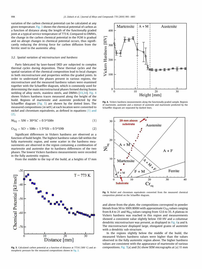
Fig. 4. Vickers hardness measurements along the functionally graded sample. Regionsof martensite, austenite and a mixture of austenite and martensite predicted by theSchaeffler diagram are separated by dashed lines.
3.2. Spatial variation of microstructure and hardness
Parts fabricated by laser-based DED are subjected to complexthermal cycles during deposition. These thermal cycles and thespatial variation of the chemical composition lead to local changesin both microstructure and properties within the graded joints. Inorder to understand the phases present in various regions, themicrostructure and the measured hardness values were examinedtogether with the Schaeffler diagram, which is commonly used fordetermining the mainmicrostructural phases formed during fusionwelding of alloy steels, stainless steels, and DMWs [33,34]. Fig. 4shows Vickers hardness traces measured along the height of thebuild. Regions of martensite and austenite predicted by theSchaeffler diagram (Fig. 5) are shown by the dotted lines. Themeasured compositions (inwt%) at each locationwere converted tonickel and chromium equivalents, as defined in equations (1) and(2),
NiEQ ¼ %Niþ 30*%C þ 0:5*%Mn (1)
CrEQ ¼ %Cr þ %Moþ 1:5*%Siþ 0:5*%Nb (2)
Significant differences in Vickers hardness are observed as afunction of build height. The highest hardness values fall within thefully martensitic region, and some scatter in the hardness mea-surements are observed in the region containing a combination ofmartensite and austenite due to hardness differences of the twophases. The lowest Vickers hardness measurements were recordedin the fully austenitic regions.
From the middle to the top of the build, at a heights of 17mm
Fig. 3. Calculated carbon potential as a function of distance at 773 K (500 �C) and at-mospheric pressure for the measured compositions shown in Fig. 2.
Fig. 5. Nickel and chromium equivalents converted from the measured chemicalcomposition plotted on the Schaeffler diagram.
and above from the plate, the compositions correspond to powderblends from 50 to 100% 800Hwith approximate CrEQ values rangingfrom 8.4 to 21 and NiEQ values ranging from 12.6 to 35. A plateau inVickers hardness was reached in this region and measurementsshowed a consistent value slightly below 150 HV and a columnardendritic microstructure was present, as displayed in Fig. 6a and b.The microstructure displayed large, elongated grains of austenitewith a dendritic sub-structure.
In the regions slightly below the middle of the build, themeasured Vickers hardness values were higher than the valuesobserved in the fully austenitic region above. The higher hardnessvalues are consistent with the appearance of martensite of variouscompositions. Fig. 7(a) and (b) show SEMmicrographs at (a) 11mm

Fig. 6. SEM micrographs approximately (a) 19mm and (b) 34mm from the baseplatein the build direction. The microstructures correspond to the 19th and 34th depositedlayer, and compositions of 50 and 100% 800H, respectively.
Fig. 7. SEM micrographs approximately (a) 11mm and (b) 15mm from the baseplatein the build direction. The microstructures correspond to the 11th and 15th depositedlayers and compositions of 30 and 40% 800H, respectively.
J.S. Zuback et al. / Journal of Alloys and Compounds 770 (2019) 995e1003 999
and (b) 15mm from the baseplate in the build direction. Sharpmartensitic laths and larger austenitic blocks are present at eachlocation. These microstructures correspond to the 11th and 15thdeposited layers and compositions of 30 and 40% 800H, respec-tively. The hardness values displayed somewhat larger scatter inthis two phase austenite and martensite region. The large standarddeviations of hardness indicate microstructural inhomogeneitiesconsisting of hard martensitic regions dispersed in a softeraustenite matrix.
To explain the varying amounts of austenite and martensite inthe two phase region, it is worthwhile to investigate the martensitetransformation temperatures. Fig. 8 shows calculations ofmartensite start temperature, Ms, 50% completion temperature,M50, and finish temperature, Mf, as a function of 800H additions.The Ms temperature is the temperature at which the free energydifference between the austenite and ferrite phases reaches acritical value for martensite nucleation [35]. At additions up to 30%800H, both Ms and Mf are above room temperature, meaning thatthe martensitic transformation is likely to reach completion. At acomposition of 40% 800H, Mf drops below room temperature,
indicating that although the transformation has started, it does notreach completion upon cooling to room temperature and someamounts of austenite are retained. After 40% 800H, the calculationsshow that the Ms values drops below room temperature, prohib-iting the martensitic transformation from ever initiating, leading tohigh amounts of austenite.
Closer to the base plate, a much harder martensitic region isobserved in the microstructure with a HV of 350 at a location 7mmabove the base. Fig. 9(a) shows the microstructure present at alocation 7mm above the baseplate corresponding to a compositionof 20% 800H. The solidification sub-grain structure of dendriteboundaries are easily observable, as further shown at highermagnification in Fig. 9(b) and displays large amounts of lathmartensite. Smaller regions of austenite appear as indicated by thewhite arrows.
Within the first 4mm of the build height, the hardness drops toa level of approximately 245± 15 HV. The composition in this re-gion corresponds to a powder blend representing 10% 800H andNiEQ and CrEQ both approximately equal to 4, which is predicted bythe Schaeffler diagram to be martensitic. Fig. 10 shows a micro-graph in the region approximately 3mm above the baseplate.

Fig. 8. Martensite start (Ms), 50% completion (M50) and finish (Mf) temperatures forthe martensite transformation as a function of composition in terms of percent 800H.
J.S. Zuback et al. / Journal of Alloys and Compounds 770 (2019) 995e10031000
While no observable grain boundaries were revealed after etching,small, plate-like structures with sharp edges were presentthroughout the region. This type of microstructure and corre-sponding hardness values are consistent with the fine-grained heataffected zone commonly observed in regions of multi-pass dis-similar welds [36], where subsequent passes reheat the material tojust above the austenization temperature. While the microstruc-ture in this region is transformed to austenite, no significant graingrowth occurs and the final ferritic grains remain very fine, usuallyon the order of tens of microns [37]. Mukherjee et al. [38] showedcomputationally that the peak temperature in the first layer duringdeposition of a second layer in a compositionally graded alloy easilyreaches a value higher than the austenization temperature of thisregion (~760 �C).
Fig. 9. (a) SEM micrograph approximately 7mm from the baseplate in the build di-rection, corresponding to the 7th deposited layer and a composition of 20% 800H and(b) a higher magnification image outlined by the white box in (a) showing martensiteand austenite.
3.3. Reduced carbon diffusion through the graded joints duringservice
The dissimilar metal welds in nuclear plants are deployed inservice at about 773 K (500 �C) for several decades before theirperformance is compromised due to metallurgical degradationresulting from carbon migration away from the ferritic side of thejoint. In order to examine the effectiveness of the FGM to overcomethis problem, both the FGM and a DMW were subjected to anaccelerated heat treatment to investigate carbon diffusion from theferritic side of the joint.
Decades of typical service conditions were simulated byselecting a temperature of heat treatment that was much higherthan the typical service temperature of 773 K. The selection of timeand temperature was based on the application of the Larson-Millerparameter,
L ¼ TðC þ logðtÞÞ (3)
where T is temperature in K, C is a material constant, and t is thetime in hours. The Larson-Miller parameter is frequently used forextrapolating experimentally measured creep data for homoge-neous materials to prolonged times at which laboratory experi-ments are not feasible. A value for C¼ 20 was chosen which
corresponds to commonly used values for applications involving2.25Cr-1Mo steel [39]. The DMW and FGM were held at 998 K for235 h (~10 days). From equation (3), this treatment has an equiv-alent L to conditions of 773 K and approximately 7.6� 108 h.
The carbon concentration profiles measured using EPMA bothbefore and after the accelerated heat treatments are shown inFigs. 11 and 12 for the DMW and FGM, respectively. The points foreach location correspond to the average values of the three linescans and the error bars represent the standard deviation. A com-parison of Fig. 11(a) and (b) show the changes in the carbon con-centration profiles of the DMW before and after heat treatment,respectively. The higher concentration of carbon close to theaustenitic side of the joint in Fig. 11(b) indicates carbon diffusionfrom ferritic to austenitic region. In contrast, when the carbonconcentration profiles of the FGM specimen before and after theaccelerated heat treatments are examined (Fig. 12(a) and (b)), therewas only a small amount of carbon accumulation observed on theaustenite side. This indicates only an insignificant amount of carbonloss from the ferritic steel after enduring service conditions that

Fig. 10. SEM micrograph approximately 3mm from the baseplate in the build direc-tion, corresponding to the 3rd deposited layer and a composition of 10% 800H.
J.S. Zuback et al. / Journal of Alloys and Compounds 770 (2019) 995e1003 1001
represent orders of magnitude longer times than required.
Fig. 11. Measured carbon concentration profiles for a DMW between 2.25Cr-1Mo steeland Alloy 800H using IN82 filler metal (a) in the as-welded condition and (b) after heattreatment.
3.4. Predicting the observed reduction of carbon diffusion
The accelerated heat treatment and the subsequent carbonconcentration profile measurements by EPMA show experimen-tally the ability of the compositionally graded joints to prevent thediffusive carbon loss from the ferritic side of the joint and avoid theadverse consequences of such loss. However, these experiments aretime consuming and expensive. Furthermore, determination ofconcentration profiles of carbon by EPMA at low carbon concen-trations suffer from large scatters. If a simulation tool can be reliedupon to predict the outcome before the accelerated diffusion ex-periments, an improved anticipation can be developed and in somecases the lengthy experiments can be avoided.
To examine the reliability of the computational tools, the carbonconcentration profiles in the accelerated carbon diffusion experi-ments were simulated. Figs. 11(b) and 12 (b) show comparisonbetween the experimentally measured carbon concentration pro-files from EPMA with the results of the simulations shown as solidlines for the DMW and FGM, respectively. The computed valuesagree well with the experimentally measured values of concen-trations. In view of the reported difficulties of carbon concentrationprofile measurements for low carbon concentrations and the abilityof the simulations to accurately predict the concentration profilesfor both DMWs and FMGs, the simulations can be used with con-fidence for examining the diffusion of carbon under serviceconditions.
Furthermore, it was shown in Fig. 1(b) and experimentally inFig. 3 that the carbon chemical potential roughly approaches aplateau after the 70% 800H region, meaning that further grading inchemical composition negligibly affects the driving force for carbondiffusion. Additionally, the microstructure in this region wasobserved to be fully austenitic and changes in chemical composi-tion had little effect on the microhardness. Therefore, a fullcomposition gradient from the ferritic to the austenitic alloy maynot be necessary to achieve the intended function.
A metric for comparing different joint designs is through thecarbon diffusion flux and resulting carbon depletion in the ferritic
steel. The carbon diffusion flux is a measure of the amount of car-bon migrating through a unit area per unit time and is dependenton both location and time. Table 2 provides the carbon diffusionfluxes in the ferritic steel after different service times at 773 K forvarious joints. The calculations take into account the change indriving force with time as the system moves towards equilibrium.
In both the full and partial FGM, approximately 100 years ofservice are required to reach the same maximum carbon depletionas a DMW in just 5 years. No differences in maximum diffusion fluxoccur when comparing a full compositional grading to a FGMgraded from 10 to 70% 800H because the chemical potential doesnot change significantly with distance for the chemical composi-tions considered. In terms of microstructure, no advantages can begained in slowing carbon diffusion once the microstructure be-comes fully austenitic, allowing for a shorter joint to suffice.Therefore, a FGM from 10 to 70% 800H is effective for limitingcarbon diffusion and provides a shorter joint design compared to afull composition gradient.

Fig. 12. Measured carbon concentration profiles for a FGM between 2.25Cr-1Mo steeland Alloy 800H (a) in the as-deposited condition and (b) after heat treatment.
Table 2Comparison of average computed carbon diffusion fluxes (mol/m2-s) and depletion in th1Mo steel and Alloy 800H.
Type of joint Nu
2
Avg. Flux (x10�13) 1.9Depletion 2.0
Avg. Flux (x10�13) 0.1Depletion 0.1
Avg. Flux (x10�13) 0.1Depletion 0.1
J.S. Zuback et al. / Journal of Alloys and Compounds 770 (2019) 995e10031002
4. Summary and conclusions
Compositional grading of transition joints was examined as ameans for limiting harmful carbon diffusion commonly encoun-tered in dissimilar metal welds between 2.25Cr-1Mo steel and Alloy800H. Compositional gradients were fabricated by laser-baseddirected energy deposition and the spatial variations of micro-structure, chemical composition, and hardness were characterized.Accelerated heat treatments of both the functionally graded jointsand dissimilar welds were conducted to test their effectiveness ofpreventing diffusive carbon loss from the ferritic alloy under ser-vice conditions. Numerical simulations of carbon diffusion duringaccelerated heat treatment as well as the carbon diffusion underservice condition for various joint designs were undertaken. Thefollowing are the main findings.
(a) The carbon chemical potential gradient as well as the carbondiffusion rate is significantly diminished by replacing thedissimilar joints with the compositionally graded joints. Ittakes approximately 5 years to deplete 5% of the initial car-bon in a dissimilar weld under typical service conditions.However, in an appropriately graded joint, it would take 100years to deplete the same amount of carbon.
(b) The chemical potential of carbon was not a linear function ofcomposition in the functionally graded transition betweenthe ferritic and austenitic alloys. The variation of chemicalpotential of carbon with distance indicates that no benefitsare gained in compositional grading after 70% 800H, becausefurther changes in composition cause no appreciablechanges in the driving force for carbon diffusion.
(c) The microstructure of the compositionally graded jointschanged gradually from martensitic near the build plate to afully austenitic structure near the top sample. Since theaustenite region does not provide any significant resistanceto carbon diffusion, a shorter transition joint can be effec-tively used to achieve the same intended retardation of car-bon diffusion.
(d) The accelerated heat treatment experiments at elevatedtemperature were designed to simulate service conditionsfor the dissimilar weld and graded joint. The functionallygraded joints significantly performed the dissimilar weld inretarding carbon diffusion under service conditions as thecarbon concentration profile remained virtually unchanged.
e ferritic steel at different service times at 773 K in dissimilar joints between 2.25Cr-
mber of years
5 10 20 50 100
7 4.94 9.87 19.6 15.2 7.85% 5.0% 10% 20% 23% 29%
57 0.392 0.785 1.57 3.92 7.852% 0.3% 0.6% 1.2% 3.1% 5.0%
57 0.392 0.785 1.57 3.92 7.852% 0.3% 0.6% 1.2% 3.1% 5.0%

J.S. Zuback et al. / Journal of Alloys and Compounds 770 (2019) 995e1003 1003
Acknowledgements
We thank Dr. Stan A. David and Dr. Thomas J. Lienert of LANL forhelpful discussions and Mr. Jay Tressler and Mr. Ed Good of PennState University for assistance with sample fabrication and metal-lographic preparation. This workwas supported by the Departmentof Energy Nuclear Energy University Program under grant numberDE-NE0008280.
References
[1] D. Roberts, R. Ryder, R. Viswanathan, Performance of dissimilar welds inservice, J. Press. Ves. 107 (3) (1985) 247e254, https://doi.org/10.1115/1.3264443.
[2] C. Lundin, Dissimilar metal welds-transition joints literature review, Weld. J.61 (2) (1982) 58e63.
[3] J. DuPont, R. Mizia, Review of Dissimilar Metal Welding for the NGNP Helical-coil Steam Generator, Idaho National Laboratory (INL), Idaho Falls, ID, 2010.
[4] J. DuPont, Microstructural evolution and high temperature failure of ferritic toaustenitic dissimilar welds, Int. Mater. Rev. 57 (4) (2012) 208e234. https://doi.org/10.1179/1743280412Y.0000000006.
[5] M. Sireesha, V. Shankar, S.K. Albert, S. Sundaresan, Microstructural features ofdissimilar welds between 316LN austenitic stainless steel and alloy 800,Mater. Sci. Eng. A 292 (1) (2000) 74e82. https://doi.org/10.1016/S0921-5093(00)00969-2.
[6] C. Jang, J. Lee, J.S. Kim, T.E. Jin, Mechanical property variation within Inconel82/182 dissimilar metal weld between low alloy steel and 316 stainless steel,Int. J. Pres. Ves. Pip. 85 (9) (2008) 635e646. https://doi.org/10.1016/j.ijpvp.2007.08.004.
[7] J. Race, H. Bhadeshia, Precipitation sequences during carburisation of CreMosteel, Mater. Sci. Tech. 8 (10) (1992) 875e882. https://doi.org/10.1179/mst.1992.8.10.875.
[8] G. Brentrup, B. Snowden, J. DuPont, J. Grenestedt, Design considerations ofgraded transition joints for welding dissimilar alloys, Weld. J. 91 (2012)252e259.
[9] H. Wang, G. Wang, F. Xuan, S. Tu, Fracture mechanism of a dissimilar metalwelded joint in nuclear power plant, Eng. Fail. Anal. 28 (2013) 134e148.https://doi.org/10.1016/j.engfailanal.2012.10.005.
[10] K. Laha, K. Chandravathi, K.B.S. Rao, S. Mannan, D. Sastry, An assessment ofcreep deformation and fracture behavior of 2.25 Cr-1Mo similar and dissim-ilar weld joints, Metall. Mater. Trans. A 32 (1) (2001) 115e124. https://doi.org/10.1007/s11661-001-0107-9.
[11] K. Laha, K.B.S. Rao, S. Mannan, Creep behaviour of post-weld heat-treated 2.25Cr-1Mo ferritic steel base, weld metal and weldments, Mater. Sci. Eng. A 129(2) (1990) 183e195. https://doi.org/10.1016/0921-5093(90)90265-5.
[12] R.M. Mahamood, E.T. Akinlabi, M. Shukla, S. Pityana, Functionally gradedmaterial: an overview, in: Proceedings of the World Congress on Engineering,London, UK, 2012, pp. 2e6.
[13] S. Kapuria, M. Bhattacharyya, A. Kumar, Bending and free vibration responseof layered functionally graded beams: a theoretical model and its experi-mental validation, Compos. Struct. 82 (3) (2008) 390e402. https://doi.org/10.1016/j.compstruct.2007.01.019.
[14] Z.H. Melgarejo, O.M. Su�arez, K. Sridharan, Wear resistance of a functionally-graded aluminum matrix composite, Scripta Mater. 55 (1) (2006) 95e98.https://doi.org/10.1016/j.scriptamat.2006.03.031.
[15] B.V. Krishna, W. Xue, S. Bose, A. Bandyopadhyay, Functionally gradedCoeCreMo coating on Tie6Ale4V alloy structures, Acta Biomater. 4 (3) (2008)697e706. https://doi.org/10.1016/j.actbio.2007.10.005.
[16] A. Bandyopadhyay, B. Krishna, W. Xue, S. Bose, Application of laser engineerednet shaping (LENS) to manufacture porous and functionally graded structuresfor load bearing implants, J. Mater. Sci Mater. M. 20 (2009) 29e34. https://doi.org/10.1007/s10856-008-3478-2.
[17] G. Brentrup, J. DuPont, Fabrication and characterization of graded transitionjoints for welding dissimilar alloys, Weld. J. 92 (2013) 72e79.
[18] B.E. Carroll, R.A. Otis, J.P. Borgonia, J.-o. Suh, R.P. Dillon, A.A. Shapiro,D.C. Hofmann, Z.-K. Liu, A.M. Beese, Functionally graded material of 304Lstainless steel and inconel 625 fabricated by directed energy deposition:characterization and thermodynamic modeling, Acta Mater. 108 (2016)46e54. https://doi.org/10.1016/j.actamat.2016.02.019.
[19] L. Murr, S. Gaytan, F. Medina, H. Lopez, E. Martinez, B. Machado, D. Hernandez,L. Martinez, M. Lopez, R. Wicker, Next-generation biomedical implants using
additive manufacturing of complex, cellular and functional mesh arrays,Philos. T. Roy. Soc. A 368 (1917) (2010) 1999e2032, https://doi.org/10.1098/rsta.2010.0010.
[20] R. Dehoff, M. Kirka, W. Sames, H. Bilheux, A. Tremsin, L. Lowe, S. Babu, Sitespecific control of crystallographic grain orientation through electron beamadditive manufacturing, Mater. Sci. Tech. 31 (8) (2015) 931e938. https://doi.org/10.1179/1743284714Y.0000000734.
[21] D.C. Hofmann, S. Roberts, R. Otis, J. Kolodziejska, R.P. Dillon, J.-o. Suh,A.A. Shapiro, Z.-K. Liu, J.-P. Borgonia, Developing gradient metal alloysthrough radial deposition additive manufacturing, Sci. Rep. 4 (2014) 5357.https://doi.org/10.1038/srep05357.
[22] T. DebRoy, H. Wei, J. Zuback, T. Mukherjee, J. Elmer, J. Milewski, A. Beese,A. Wilson-Heid, A. De, W. Zhang, Additive manufacturing of metalliccomponentseprocess, structure and properties, Prog. Mater. Sci. 92 (2018)112e224. https://doi.org/10.1016/j.pmatsci.2017.10.001.
[23] U. Savitha, G.J. Reddy, A. Venkataramana, A.S. Rao, A. Gokhale,M. Sundararaman, Chemical analysis, structure and mechanical properties ofdiscrete and compositionally graded SS316eIN625 dual materials, Mater. Sci.Eng. A 647 (2015) 344e352. https://doi.org/10.1016/j.msea.2015.09.001.
[24] C. Shen, Z. Pan, D. Cuiuri, J. Roberts, H. Li, Fabrication of Fe-FeAl functionallygraded material using the wire-arc additive manufacturing process, Metall.Mater. Trans. B 47 (1) (2016) 763e772. https://doi.org/10.1007/s11663-015-0509-5.
[25] P. Muller, P. Mognol, J.-Y. Hascoet, Modeling and control of a direct laserpowder deposition process for Functionally Graded Materials (FGM) partsmanufacturing, J. Mater. Process. Technol. 213 (5) (2013) 685e692. https://doi.org/10.1016/j.jmatprotec.2012.11.020.
[26] M. Domack, J. Baughman, Development of nickel-titanium graded composi-tion components, Rapid Prototyp. J. 11 (1) (2005) 41e51. https://doi.org/10.1108/13552540510573383.
[27] L.D. Bobbio, R.A. Otis, J.P. Borgonia, R.P. Dillon, A.A. Shapiro, Z.-K. Liu,A.M. Beese, Additive manufacturing of a functionally graded material from Ti-6Al-4V to Invar: experimental characterization and thermodynamic calcula-tions, Acta Mater. 127 (2017) 133e142. https://doi.org/10.1016/j.actamat.2016.12.070.
[28] P. Collins, R. Banerjee, S. Banerjee, H. Fraser, Laser deposition of composi-tionally graded titaniumevanadium and titaniumemolybdenum alloys,Mater. Sci. Eng. A 352 (1) (2003) 118e128. https://doi.org/10.1016/S0921-5093(02)00909-7.
[29] Z. Khayat, T. Palmer, Impact of iron composition on the properties of anadditively manufactured solid solution strengthened nickel base alloy, Mater.Sci. Eng., A 718 (2018) 123e134. https://doi.org/10.1016/j.msea.2018.01.112.
[30] J.S. Keist, T.A. Palmer, Role of geometry on properties of additively manufac-tured Ti-6Al-4V structures fabricated using laser based directed energydeposition, Mater. Des. 106 (2016) 482e494. https://doi.org/10.1016/j.matdes.2016.05.045.
[31] E.R. Denlinger, J.C. Heigel, P. Michaleris, T. Palmer, Effect of inter-layer dwelltime on distortion and residual stress in additive manufacturing of titaniumand nickel alloys, J. Mater. Process. Technol. 215 (2015) 123e131. https://doi.org/10.1016/j.jmatprotec.2014.07.030.
[32] N. Saunders, A.P. Miodownik, CALPHAD (calculation of Phase Diagrams): aComprehensive Guide, Elsevier, 1998.
[33] J.N. DuPont, J.C. Lippold, S.D. Kiser, Welding Metallurgy and Weldability ofNickel-base Alloys, John Wiley & Sons, Hoboken, NJ, 2009.
[34] A. Schaeffler, Constitution diagram for stainless steel weld metal, Metal Prog.56 (11) (1949) 680.
[35] G. Ghosh, G. Olson, Computational thermodynamics and the kinetics ofmartensitic transformation, J. Phase Equil. 22 (3) (2001) 199. https://doi.org/10.1361/105497101770338653.
[36] A. Elrefaey, Y. Javadi, J.A. Francis, M.D. Callaghan, A.J. Leonard, Evolution ofmicrostructure and toughness in 2.25 Cr-1Mo steel welds, Int. J. Pres. Ves. Pip.(2018). https://doi.org/10.1016/j.ijpvp.2018.05.006.
[37] P. Mayr, C. Schlacher, J.A. Siefert, J.D. Parker, Microstructural features, me-chanical properties and high temperature failures of ferritic to ferritic dis-similar welds, Int. Mater. Rev. (2018) 1e26. https://doi.org/10.1080/09506608.2017.1410943.
[38] T. Mukherjee, J. Zuback, W. Zhang, T. DebRoy, Residual stresses and distortionin additively manufactured compositionally graded and dissimilar joints,Comput. Mater. Sci. 143 (2018) 325e337. https://doi.org/10.1016/j.commatsci.2017.11.026.
[39] R. Klueh, A. Nelson, Ferritic/martensitic steels for next-generation reactors,J. Nucl. Mater. 371 (1) (2007) 37e52. https://doi.org/10.1016/j.jnucmat.2007.05.005.