CS 800H Operations Manual power amplifier · CS®800H Operations Manual For more information on...
60
CS ® 800H Operations Manual For more information on other great Peavey products, go to your local Peavey dealer or online at www.peavey.com power amplifier
Transcript of CS 800H Operations Manual power amplifier · CS®800H Operations Manual For more information on...
CS®800H Operations Manual
For more information on other great Peavey products, go to your local Peavey dealer or online at www.peavey.com
power amplifier
2
Intended to alert the user to the presence of uninsulated “dangerous voltage” within the product’s
enclosure that may be of sufficient magnitude to constitute a risk of electric shock to persons.
Intended to alert the user of the presence of important operating and maintenance (servicing)
instructions in the literature accompanying the product.
CCAAUUTTIIOONN:: Risk of electrical shock — DO NOT OPEN!
CCAAUUTTIIOONN:: To reduce the risk of electric shock, do not remove cover. No user serviceable parts inside.
Refer servicing to qualified service personnel.
WWAARRNNIINNGG:: To prevent electrical shock or fire hazard, do not expose this appliance to rain or moisture.
Before using this appliance, read the operating guide for further warnings.
Este símbolo tiene el propósito, de alertar al usuario de la presencia de “(voltaje) peligroso” sin
aislamiento dentro de la caja del producto y que puede tener una magnitud suficiente como para
constituir riesgo de descarga eléctrica.
Este símbolo tiene el propósito de alertar al usario de la presencia de instruccones importantes sobre la
operación y mantenimiento en la información que viene con el producto.
PPRREECCAAUUCCIIOONN:: Riesgo de descarga eléctrica ¡NO ABRIR!
PPRREECCAAUUCCIIOONN:: Para disminuír el riesgo de descarga eléctrica, no abra la cubierta. No hay piezas útiles
dentro. Deje todo mantenimiento en manos del personal técnico cualificado.
AADDVVEERRTTEENNCCIIAA:: Para evitar descargas eléctricas o peligro de incendio, no deje expuesto a la lluvia o
humedad este aparato Antes de usar este aparato, Iea más advertencias en la guía de operación.
Ce symbole est utilisé dans ce manuel pour indiquer à l’utilisateur la présence d’une tension dangereuse
pouvant être d’amplitude suffisante pour constituer un risque de choc électrique.
Ce symbole est utilisé dans ce manuel pour indiquer à l’utilisateur qu’il ou qu’elle trouvera d’importantes
instructions concernant l’utilisation et l’entretien de l’appareil dans le paragraphe signalé.
AATTTTEENNTTIIOONN:: Risques de choc électrique — NE PAS OUVRIR!
AATTTTEENNTTIIOONN:: Afin de réduire le risque de choc électrique, ne pas enlever le couvercle. Il ne se trouve à
l’intérieur aucune pièce pouvant être reparée par l’utilisateur. Confiez I’entretien et la réparation de
l’appareil à un réparateur Peavey agréé.
AAVVEERRTTIISSSSEEMMEENNTT: Afin de prévenir les risques de décharge électrique ou de feu, n’exposez pas cet
appareil à la pluie ou à l’humidité. Avant d’utiliser cet appareil, lisez attentivement les avertissements
supplémentaires de ce manuel.
Dieses Symbol soll den Anwender vor unisolierten gefährlichen Spannungen innerhalb des Gehäuses
warnen, die von Ausreichender Stärke sind, um einen elektrischen Schlag verursachen zu können.
Dieses Symbol soll den Benutzer auf wichtige Instruktionen in der Bedienungsanleitung aufmerksam
machen, die Handhabung und Wartung des Produkts betreffen.
VVOORRSSIICCHHTT:: Risiko — Elektrischer Schlag! Nicht öffnen!
VVOORRSSIICCHHTT:: Um das Risiko eines elektrischen Schlages zu vermeiden, nicht die Abdeckung enfernen. Es
befinden sich keine Teile darin, die vom Anwender repariert werden könnten. Reparaturen nur von
qualifiziertem Fachpersonal durchführen lassen.
AACCHHTTUUNNGG:: Um einen elektrischen Schlag oder Feuergefahr zu vermeiden, sollte dieses Gerät nicht dem
Regen oder Feuchtigkeit ausgesetzt werden. Vor Inbetriebnahme unbedingt die Bedienungsanleitung lesen.
3
IIMMPPOORRTTAANNTT SSAAFFEETTYY IINNSSTTRRUUCCTTIIOONNSS
WWAARRNNIINNGG:: When using electrical products, basic cautions should always be followed, including the following:
1. Read these instructions.
2. Keep these instructions.
3. Heed all warnings.
4. Follow all instructions.
5. Do not use this apparatus near water.
6. Clean only with a dry cloth.
7. Do not block any of the ventilation openings. Install in accordance with manufacturer’s instructions.
8. Do not install near any heat sources such as radiators, heat registers, stoves or other apparatus (including amplifiers)
that produce heat.
9. Do not defeat the safety purpose of the polarized or grounding-type plug. A polarized plug has two blades with one
wider than the other. A grounding type plug has two blades and a third grounding plug. The wide blade or third prong is
provided for your safety. If the provided plug does not fit into your outlet, consult an electrician for replacement of the
obsolete outlet.
10. Protect the power cord from being walked on or pinched, particularly at plugs, convenience receptacles, and the point
they exit from the apparatus.
11. Note for UK only: If the colors of the wires in the mains lead of this unit do not correspond with the terminals in your
plug‚ proceed as follows:
a) The wire that is colored green and yellow must be connected to the terminal that is marked by the letter E‚ the earth
symbol‚ colored green or colored green and yellow.
b) The wire that is colored blue must be connected to the terminal that is marked with the letter N or the color black.
c) The wire that is colored brown must be connected to the terminal that is marked with the letter L or the color red.
12. Only use attachments/accessories provided by the manufacturer.
13. Use only with a cart, stand, tripod, bracket, or table specified by the manufacturer, or sold with the apparatus. When a
cart is used, use caution when moving the cart/apparatus combination to avoid injury from tip-over.
14. Unplug this apparatus during lightning storms or when unused for long periods of time.
15. Refer all servicing to qualified service personnel. Servicing is required when the apparatus has been damaged in any
way, such as power-supply cord or plug is damaged, liquid has been spilled or objects have fallen into the apparatus,
the apparatus has been exposed to rain or moisture, does not operate normally, or has been dropped.
16. Never break off the ground pin. Write for our free booklet “Shock Hazard and Grounding.” Connect only to a power
supply of the type marked on the unit adjacent to the power supply cord.
17. If this product is to be mounted in an equipment rack, rear support should be provided.
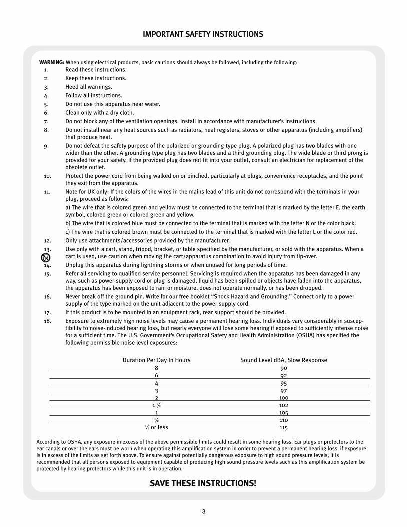
18. Exposure to extremely high noise levels may cause a permanent hearing loss. Individuals vary considerably in suscep-
tibility to noise-induced hearing loss, but nearly everyone will lose some hearing if exposed to sufficiently intense noise
for a sufficient time. The U.S. Government’s Occupational Safety and Health Administration (OSHA) has specified the
following permissible noise level exposures:
Duration Per Day In Hours Sound Level dBA, Slow Response
8 90
6 92
4 95
3 97
2 100
1 1⁄2 102
1 1051⁄2 110
1⁄4 or less 115
According to OSHA, any exposure in excess of the above permissible limits could result in some hearing loss. Ear plugs or protectors to the
ear canals or over the ears must be worn when operating this amplification system in order to prevent a permanent hearing loss, if exposure
is in excess of the limits as set forth above. To ensure against potentially dangerous exposure to high sound pressure levels, it is
recommended that all persons exposed to equipment capable of producing high sound pressure levels such as this amplification system be
protected by hearing protectors while this unit is in operation.
SSAAVVEE TTHHEESSEE IINNSSTTRRUUCCTTIIOONNSS!!
4
CCSS®® 880000HH PPoowweerr AAmmpplliiffiieerr
Congratulations on your purchase of the CS 800H power amplifier from Peavey—designed for years of
reliable, flawless operation under rigorous use. This amplifier offers the sonic superiority and
unsurpassed reliability for which Peavey is famous, while remaining surprisingly compact. Advanced
technology and extensive protection circuitry allow operation with greater efficiency into difficult
loads and power conditions. The DDDDTT™ (Distortion Detection) circuit ensures trouble-free operation
into loads as low as 2 Ohms. The Distortion Detection circuits protect drivers and ensure that sonic
integrity is maintained, even in extreme overload conditions. Peavey’s hi-efficiency design uses
patented Turbo-V cooling and variable speed DC fan. This cooling topology maintains a lower overall
operating temperature, resulting in longer output transistor life.
Although the Peavey CS 800H amplifier is quite simple to operate and is housed in ultra-strong steel
chassis, improper use can be dangerous. This amplifier is very high-powered and can put out high
voltages and sizable currents at frequencies up to 30 kHz. Always use safe operating techniques
when operating this amplifier.
FFOORR YYOOUURR SSAAFFEETTYY,, RREEAADD TTHHEE IIMMPPOORRTTAANNTT PPRREECCAAUUTTIIOONNSS SSEECCTTIIOONN,, AASS WWEELLLL AASS IINNPPUUTT,, OOUUTTPPUUTT,, AANNDD
PPOOWWEERR CCOONNNNEECCTTIIOONN SSEECCTTIIOONNSS..
·· 1199"" 22--ssppaaccee‚‚ rraacckk--mmoouunnttaabbllee ddeessiiggnn
·· ppaatteenntteedd TTuurrbboo--VV ccoooolleedd hheeaatt ssiinnkkss wwiitthh vvaarriiaabbllee ssppeeeedd DDCC ffaann
·· uullttrraa--ssttrreennggtthh sstteeeell cchhaassssiiss
·· RRaammppUUpp™™ ssiiggnnaall ccoonnttrrooll
·· sstteerreeoo oorr bbrriiddggeedd--mmoonnoo mmooddeess ooff ooppeerraattiioonn
·· ffrroonntt ppaanneell AACC ppoowweerr sswwiittcchh//cciirrccuuiitt bbrreeaakkeerr
·· aammpp ffuunnccttiioonn sswwiittcchh ffoorr ffuullll--rraannggee ooppeerraattiioonn oorr ccrroossssoovveerr hhiigghh//llooww ffrreeqquueennccyy oouuttppuuttss
·· ttwwoo iinnddeeppeennddeenntt‚‚ aaddjjuussttaabbllee ccrroossssoovveerrss
·· ttwwoo iinnddeeppeennddeenntt‚‚ llooww ffrreeqquueennccyy ffiilltteerrss
·· ffiivvee ffrroonntt ppaanneell LLEEDD iinnddiiccaattoorrss ppeerr cchhaannnneell:: AACCTTIIVVEE,, DDDDTT™™,, SSIIGGNNAALL‚‚ TTEEMMPP aanndd DDCC
UUnnppaacckkiinngg
Upon unpacking, inspect the amplifier. If you find any damage, notify your supplier immediately. Only
the consignee may institute a claim with the carrier for damage incurred during shipping. Be sure to
save the carton and all packing materials. Should you ever need to ship the unit back to Peavey
Electronics, one of its offices, service centers, or the supplier, use only the original factory packing. If
the shipping carton is unavailable, contact Peavey to obtain a replacement.
MMoouunnttiinngg
The CS 800H amplifier will mount in standard 19-inch racks. Rear mounting ears are also provided for
additional support, which is recommended in non-permanent installations like mobile or touring
sound systems. Because of the cables and connectors on the rear panel, a right angle or offset
screwdriver or hex key will make it easier to fasten the rear mounting ears to the rails.
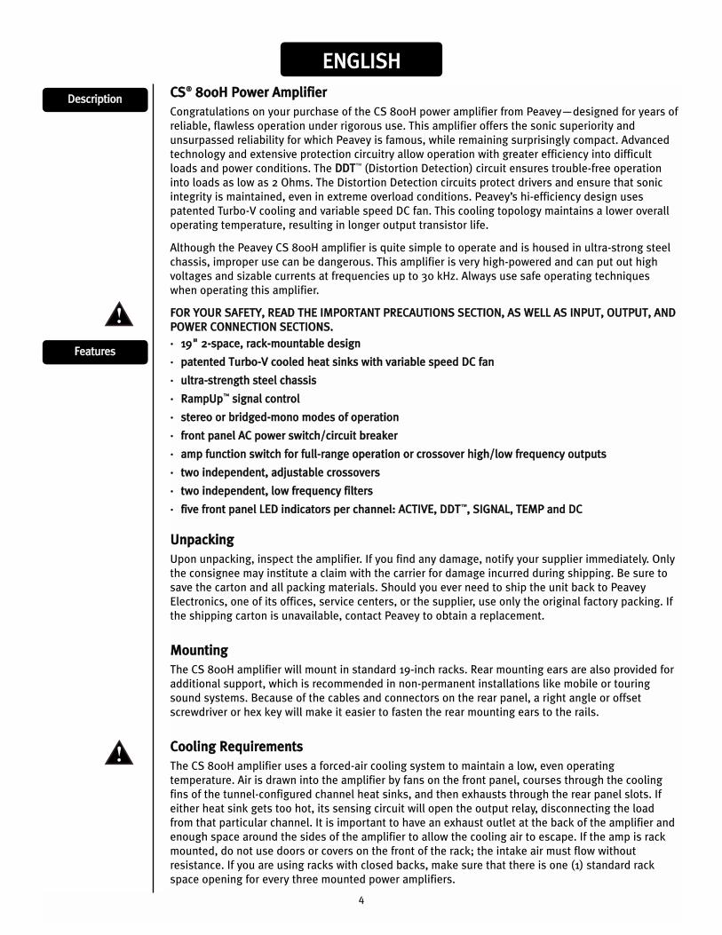
CCoooolliinngg RReeqquuiirreemmeennttss
The CS 800H amplifier uses a forced-air cooling system to maintain a low, even operating
temperature. Air is drawn into the amplifier by fans on the front panel, courses through the cooling
fins of the tunnel-configured channel heat sinks, and then exhausts through the rear panel slots. If
either heat sink gets too hot, its sensing circuit will open the output relay, disconnecting the load
from that particular channel. It is important to have an exhaust outlet at the back of the amplifier and
enough space around the sides of the amplifier to allow the cooling air to escape. If the amp is rack
mounted, do not use doors or covers on the front of the rack; the intake air must flow without
resistance. If you are using racks with closed backs, make sure that there is one (1) standard rack
space opening for every three mounted power amplifiers.
EENNGGLLIISSHH
FFeeaattuurreess
DDeessccrriippttiioonn

5
OOppeerraattiinngg PPrreeccaauuttiioonnss
Make sure the mains voltage is correct and is the same as that printed on the rear of the amplifier.
Damage caused by connecting the amplifier to improper AC voltage is not covered by any warranty. See
the Connecting Power section for more information on voltage requirements.
NNoottee:: AAllwwaayyss ttuurrnn ooffff aanndd ddiissccoonnnneecctt tthhee aammpplliiff iieerr ffrroomm mmaaiinnss vvoollttaaggee bbeeffoorree mmaakkiinngg
aauuddiioo ccoonnnneeccttiioonnss.. AAllssoo,, aass aann eexxttrraa pprreeccaauuttiioonn,, hhaavvee tthhee aatttteennuuaattoorrss ttuurrnneedd ddoowwnn
dduurriinngg ppoowweerr--uupp..
Although the CS 800H amplifier has RRaammppUUpp™ circuitry, which raises the signal level gradually after the
output relay closes, it is always a good idea to have the gain controls turned down during power-up to
prevent speaker damage if there is a high signal level at the inputs. Whether you buy or make them, use
good-quality connections, input cables and speaker cables, along with good soldering technique, to
ensure trouble-free operation. Most intermittent problems are caused by faulty cables.
Consult the Wire Gauge Chart (below) to determine proper gauges for different load impedances and
cable lengths. Remember that cable resistance robs amplifier power in two ways: power lost directly to
resistance (I2R loss), and by lowering the total load impedance. Also make sure the mode switch is
correctly set for the desired application. See Sections on SStteerreeoo and BBrriiddggeedd MMoonnoo operation for more
information.
W I R E G A U G E C H A R T
Cable Length(In Feet)
Stranded Wire Gauge(AWG)
Power Loss into 8 Ohms (%)
Power Loss into 4 Ohms (%)
Power Loss into 2 Ohms (%)
5 18 .79 1.58 3.16
16 .50 1.00 2.00
14 .31 .62 1.24
12 .20 .40 .80
10 .125 .25 .50
10 18 1.58 3.16 6.32
16 1.00 2.00 4.00
14 .62 1.25 2.50
12 .40 .80 1.60
10 .25 .50 1.00
40 18 8.00 12.60 25.20
. 16 4.00 8.00 1.60
14 2.50 5.00 10.00
12 1.60 3.20 6.40
10 1.00 2.00 4.00
8 .625 1.25 2.50
80 16 8.00 16.00 32.00
14 5.00 10.00 20.00
12 3.20 6.40 12.80
10 2.00 4.00 8.00
6
CCoonnnneeccttiinngg IInnppuuttss
Input connections are made via the 3-pin XLR (pin 2+) or 6.3 mm plug “Combi” connectors on the
rear panel of the amplifier. The inputs are actively balanced. Pinout and polarity of connection
cables should be configured correctly (refer to the rear panel of the unit). The input overload
point is high enough to accept the maximum output level of virtually any signal source.
CCoonnnneeccttiinngg OOuuttppuuttss
All models have two output (speaker) connections per channel. Cables can be connected with
banana plugs, spade lugs, or bare wire to the 5-way binding posts. The preferred connection
method is via the Speakon connectors. Pin connections are noted on the rear panel of the unit.
CCoonnnneeccttiinngg PPoowweerr
The CS 800H power requirements are rated at 1/8 power (typical music conditions). The
maximum power current draw rating is limited only by the front panel circuit breaker. Consult the
specifications in this manual for figures on the current that this amplifier will demand. Make sure
the mains voltage is correct and is the same as that printed on the rear of the amplifier. Damage
caused by connecting the amplifier to improper AC voltage is not covered by any warranty. Unless
otherwise specified when ordered, Peavey amplifiers shipped to customers are configured as
follows:
North America: 120 VAC/60 Hz
Europe, Asia, Australia: 230/240 VAC/50 Hz
South America: 120 VAC/60 Hz or 240 VAC/50 Hz
SStteerreeooFor stereo (dual channel) operation, turn the amplifier off and set the mode select switch to the
stereo position. In this mode, both channels operate independently of each other, with their
input attenuators controlling their respective levels. Thus, a signal at Channel A’s input produces
an amplified signal at Channel A’s output, while a signal at Channel B’s input produces an
amplified signal at Channel B’s output.
BBrriiddggeedd MMoonnooBoth amplifier channels can be bridged together to make a very powerful single-channel
monaural amplifier. Use extreme caution when operating in the bridged mode; high voltage may
be present at the output terminals. To bridge the amplifier, set the rear panel mode select switch
to the bridge position. Apply the signal to Channel A’s input (all Channel B’s input functions are
defeated) and connect the speakers across the hot outputs (the “+” binding posts of Channels A
and B) or between the 1+ and 2+ pins of the Channel A Speakon® connector. The input level
control for channel A will be the master control for input level, the level control for the B channel
is inoperative. The active LED for the B channel will not light, which makes it easy to identify
when the amp is in Bridge mode.
Unlike stereo mode, in which one side of each output is at ground, in the bridged mode both
sides are hot. If an output patch panel is used, all connections must be isolated from each other
and from the panel. The recommended minimum nominal load impedance in the bridged mode is
4 Ohms (equivalent to driving both channels at 2 Ohms). Driving bridged loads of less than 4
Ohms can activate the Load Fault Correction (LFC) circuitry resulting in a limiting of power, and
may also cause a thermal overload.
OOppeerraattiioonn MMooddeess
7
AACC PPoowweerr SSwwiittcchh//CCiirrccuuiitt BBrreeaakkeerr ((11))The CS 800H amplifier has a combination AC switch/circuit breaker on the front panel. If the switch
shuts off during normal use, push it back to the ON position once. If it will not stay on, the amplifier
needs servicing.
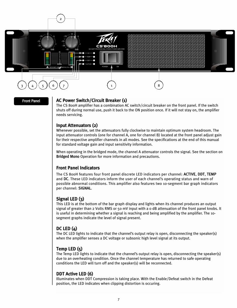
IInnppuutt AAtttteennuuaattoorrss ((22))Whenever possible, set the attenuators fully clockwise to maintain optimum system headroom. The
input attenuator controls (one for channel A, one for channel B) located at the front panel adjust gain
for their respective amplifier channels in all modes. See the specifications at the end of this manual
for standard voltage gain and input sensitivity information.
When operating in the bridged mode, the channel A attenuator controls the signal. See the section on
BBrriiddggeedd MMoonnoo Operation for more information and precautions.
FFrroonntt PPaanneell IInnddiiccaattoorrss
The CS 800H features four front panel discrete LED indicators per channel: AACCTTIIVVEE, DDDDTT, TTEEMMPP
and DDCC. These LED indicators inform the user of each channel’s operating status and warn of
possible abnormal conditions. This amplifier also features two 10-segment bar graph indicators
per channel: SSIIGGNNAALL.
SSiiggnnaall LLEEDD ((33)) This LED is at the bottom of the bar graph display and lights when its channel produces an output
signal of greater than 2 Volts RMS or 50 mV input with a 0 dB attenuation of the front panel knobs. It
is useful in determining whether a signal is reaching and being amplified by the amplifier. The 10-
segment graphs indicate the level of signal present.
DDCC LLEEDD ((44))The DC LED lights to indicate that the channel’s output relay is open, disconnecting the speaker(s)
when the amplifier senses a DC voltage or subsonic high level signal at its output.
TTeemmpp LLEEDD ((55))The Temp LED lights to indicate that the channel’s output relay is open, disconnecting the speaker(s)
due to an overheating condition. Once the channel temperature has returned to safe operating
conditions the LED will turn off and the speaker(s) will be reconnected.
DDDDTT AAccttiivvee LLEEDD ((66))Illuminates when DDT Compression is taking place. With the Enable/Defeat switch in the Defeat
position, the LED indicates when clipping distortion is occuring.
2
1 8
FFrroonntt PPaanneell
4 5 6 73
8
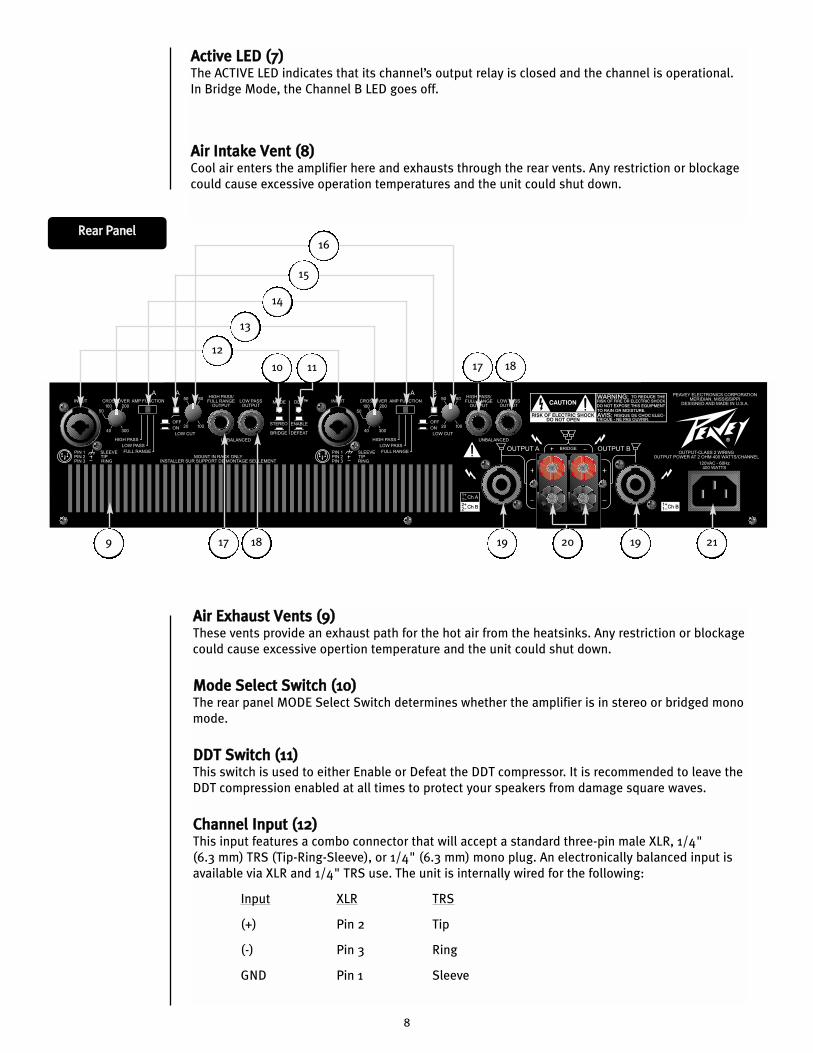
AAiirr EExxhhaauusstt VVeennttss ((99))These vents provide an exhaust path for the hot air from the heatsinks. Any restriction or blockage
could cause excessive opertion temperature and the unit could shut down.
MMooddee SSeelleecctt SSwwiittcchh ((1100))The rear panel MODE Select Switch determines whether the amplifier is in stereo or bridged mono
mode.
DDDDTT SSwwiittcchh ((1111))This switch is used to either Enable or Defeat the DDT compressor. It is recommended to leave the
DDT compression enabled at all times to protect your speakers from damage square waves.
CChhaannnneell IInnppuutt ((1122))This input features a combo connector that will accept a standard three-pin male XLR, 1/4"
(6.3 mm) TRS (Tip-Ring-Sleeve), or 1/4" (6.3 mm) mono plug. An electronically balanced input is
available via XLR and 1/4" TRS use. The unit is internally wired for the following:
Input XLR TRS
(+) Pin 2 Tip
(-) Pin 3 Ring
GND Pin 1 Sleeve
RReeaarr PPaanneell
12
10 11
AAccttiivvee LLEEDD ((77))The ACTIVE LED indicates that its channel’s output relay is closed and the channel is operational.
In Bridge Mode, the Channel B LED goes off.
AAiirr IInnttaakkee VVeenntt ((88))Cool air enters the amplifier here and exhausts through the rear vents. Any restriction or blockage
could cause excessive operation temperatures and the unit could shut down.
17 18 19 19 2120
17 18
9
13
14
15
16
9
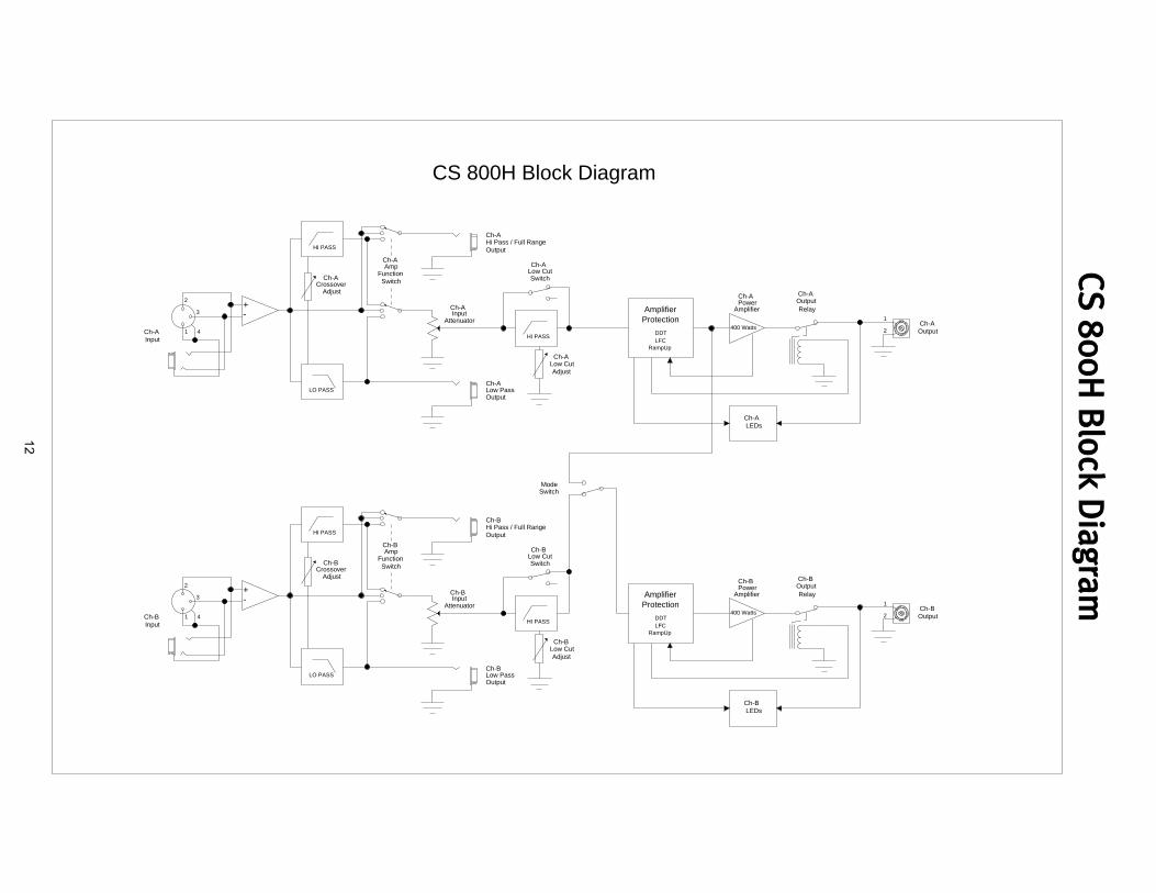
CCrroossssoovveerr AAddjjuussttmmeenntt KKnnoobb ((1133))The CS 800H is equipped with two independent‚ two-way crossovers adjustable from 40 Hz to 300 Hz.
These crossover frequencies are appropriate for use with a subwoofer system. The output of these
crossovers is selected by the Amp Function switch and connected to the corresponding amplifier
channel. Frequencies above the knob setting will be connected to the corresponding channel when the
Amp Function switch is in the HIGH PASS position. Frequencies below the knob setting will be
connected to the corresponding channel when the Amp Function switch is in the LOW PASS position.
The FULL RANGE position bypasses the crossover.
AAmmpp FFuunnccttiioonn SSwwiittcchh ((1144))The rear panel Amp Function Select Switch determines whether the associated channel is connected for
full range operation or to the crossover high frequency or low frequency outputs.
LLooww CCuutt SSwwiittcchh ((1155))The LOW CUT switch is a recessed push switch used to defeat or engage the LOW CUT filter. Pushing the
switch to the in position will engage the filter.
LLooww CCuutt AAddjjuussttmmeenntt KKnnoobb ((1166))The CS 800H is equipped with two independent low frequency filters. These filters are adjustable from
20 Hz to 100 Hz and are designed to reduce frequencies below those capable of being produced by the
loudspeakers, or to reduce room “rumble.” Frequencies below the knob setting of the corresponding
channel will be attenuated.
HHiigghh PPaassss//FFuullll RRaannggee OOuuttppuutt CCoonnnneeccttoorr ((1177))The HIGH PASS/FULL RANGE OUTPUT connector function is dependent on the setting of the
corresponding Amp Function switch. This connector allows patching the frequencies above the
crossover knob setting to a secondary amplifier. If the Amp Function switch is in the HIGH PASS
position, the high frequency portion of the crossover will be present at the connector. If the Amp
Function switch is in the FULL RANGE or LOW PASS position, the crossover will be bypassed and allow
patching the full range signal to a secondary amplifier.
LLooww PPaassss OOuuttppuutt CCoonnnneeccttoorr ((1188))The LOW PASS OUTPUT connector allows patching the frequencies below the crossover knob setting to
a secondary amplifier. This output remains at low frequencies independent of the Amp Function switch
setting.
SSppeeaakkoonn®® OOuuttppuutt CCoonnnneeccttoorr ((1199))Each channel features a four-wire Speakon connector for the output. In both channels, the 1+ pin is the
channel signal output and the 1- pin is chassis ground. On the Channel A connector, the 2+ pin carries
the Channel B signal output and the 2- pin is chassis ground.
BBiinnddiinngg PPoosstt OOuuttppuutt CCoonnnneeccttoorrss ((2200))Each channel features a pair of shock-proof binding posts connected in parallel with the Speakon
connector. The red binding posts are the signal output from each channel, and the black binding posts
are chassis ground. For Bridge mode operation, only the red binding posts are used. The Channel A red
binding post should be considered the positive output for the system and should be connected to the
positive input of the associated loudspeaker system.
AACC LLiinnee CCoorrdd CCoonnnneeccttoorr ((2211))Provided to accept the removable (IEC) type AC line cord. Connect only to proper source (see back panel
markings).
10
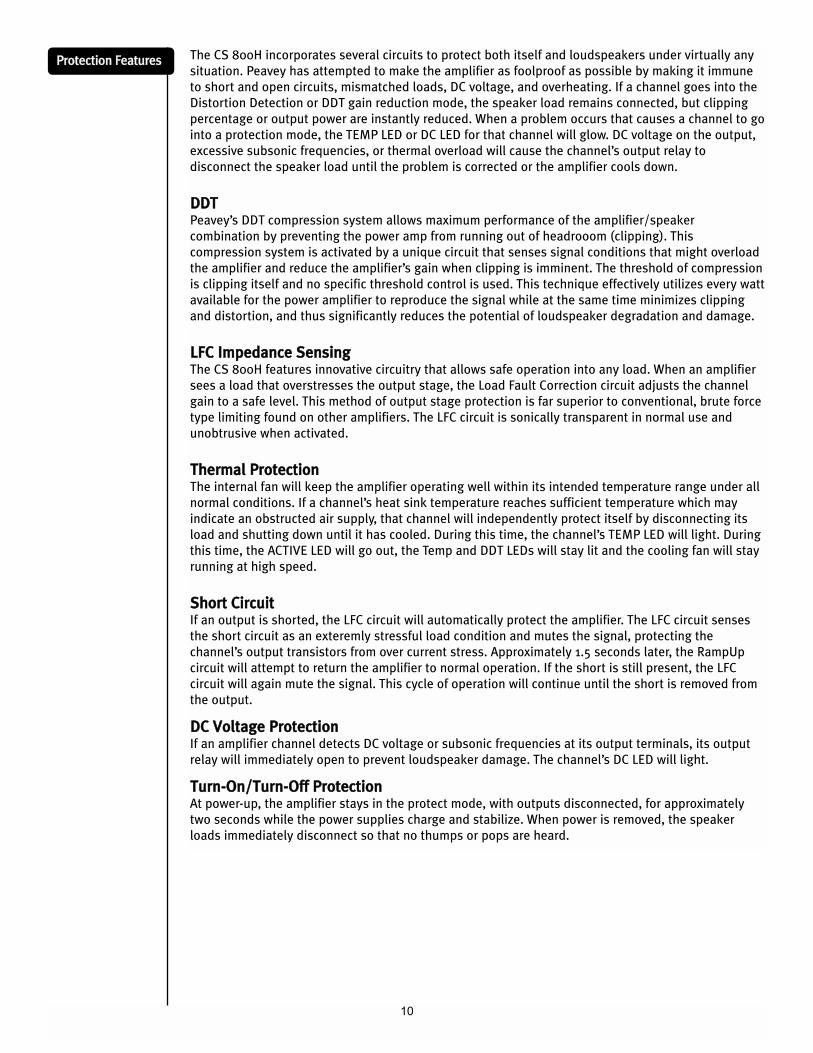
The CS 800H incorporates several circuits to protect both itself and loudspeakers under virtually any
situation. Peavey has attempted to make the amplifier as foolproof as possible by making it immune
to short and open circuits, mismatched loads, DC voltage, and overheating. If a channel goes into the
Distortion Detection or DDT gain reduction mode, the speaker load remains connected, but clipping
percentage or output power are instantly reduced. When a problem occurs that causes a channel to go
into a protection mode, the TEMP LED or DC LED for that channel will glow. DC voltage on the output,
excessive subsonic frequencies, or thermal overload will cause the channel’s output relay to
disconnect the speaker load until the problem is corrected or the amplifier cools down.
DDDDTTPeavey’s DDT compression system allows maximum performance of the amplifier/speaker
combination by preventing the power amp from running out of headrooom (clipping). This
compression system is activated by a unique circuit that senses signal conditions that might overload
the amplifier and reduce the amplifier’s gain when clipping is imminent. The threshold of compression
is clipping itself and no specific threshold control is used. This technique effectively utilizes every watt
available for the power amplifier to reproduce the signal while at the same time minimizes clipping
and distortion, and thus significantly reduces the potential of loudspeaker degradation and damage.
LLFFCC IImmppeeddaannccee SSeennssiinnggThe CS 800H features innovative circuitry that allows safe operation into any load. When an amplifier
sees a load that overstresses the output stage, the Load Fault Correction circuit adjusts the channel
gain to a safe level. This method of output stage protection is far superior to conventional, brute force
type limiting found on other amplifiers. The LFC circuit is sonically transparent in normal use and
unobtrusive when activated.
TThheerrmmaall PPrrootteeccttiioonnThe internal fan will keep the amplifier operating well within its intended temperature range under all
normal conditions. If a channel’s heat sink temperature reaches sufficient temperature which may
indicate an obstructed air supply, that channel will independently protect itself by disconnecting its
load and shutting down until it has cooled. During this time, the channel’s TEMP LED will light. During
this time, the ACTIVE LED will go out, the Temp and DDT LEDs will stay lit and the cooling fan will stay
running at high speed.
SShhoorrtt CCiirrccuuiittIf an output is shorted, the LFC circuit will automatically protect the amplifier. The LFC circuit senses
the short circuit as an exteremly stressful load condition and mutes the signal, protecting the
channel’s output transistors from over current stress. Approximately 1.5 seconds later, the RampUp
circuit will attempt to return the amplifier to normal operation. If the short is still present, the LFC
circuit will again mute the signal. This cycle of operation will continue until the short is removed from
the output.
DDCC VVoollttaaggee PPrrootteeccttiioonnIf an amplifier channel detects DC voltage or subsonic frequencies at its output terminals, its output
relay will immediately open to prevent loudspeaker damage. The channel’s DC LED will light.
TTuurrnn--OOnn//TTuurrnn--OOffff PPrrootteeccttiioonnAt power-up, the amplifier stays in the protect mode, with outputs disconnected, for approximately
two seconds while the power supplies charge and stabilize. When power is removed, the speaker
loads immediately disconnect so that no thumps or pops are heard.
PPrrootteeccttiioonn FFeeaattuurreess
11
RRaammppUUpp™™ SSiiggnnaall CCoonnttrroollWhenever amplifier powers up or comes out of a protect mode, the RampUp™ circuit activates. While
the speakers are disconnected, the RampUp™ circuit fully attenuates the signal. After the output relay
closes, the signal slowly and gradually raises up to its set level. The RampUp™ Signal Control circuit has
some important advantages over the conventional instant-on circuits:
If a signal is present during power-up (or when coming out of protect), the speakers are
spared a sudden, potentially damaging burst of audio power.
Because the gain is reduced until after the output relay closes, no arcing occurs at the
contacts, thereby extending their useful life.
SSppeeaakkeerr PPrrootteeccttiioonnAll loudspeakers have electrical, thermal and physical limits that must be observed to prevent damage
or failure. Too much power, low frequencies applied to high frequency drivers, severely clipped
waveforms, and DC voltage can all be fatal to cone and compression drivers. The Peavey CS 800H
amplifier automatically protects speakers from DC voltages and subsonic signals. For more information,
see the section on Protection Features. Mid- and high-frequency speakers, especially compression
drivers, are highly susceptible to damage from overpowering, clipped waveforms, or frequencies below
their rated pass band. Be extremely careful that the low and mid bands of an electronic crossover are
connected to the correct amplifiers and drivers and not accidentally connected to those for a lower
frequency band. The amplifier’s clipping point is its maximum peak output power, and the high power
Peavey CS 800H amplifier can deliver more power than many speakers can safely handle. Be sure the
peak power capability of the amplifier is not excessive for your speaker system.
Fuses may also be used to limit power to speaker drivers, although as current-limiting rather than
voltage-limiting devices, they are an imperfect solution, and as the weakest links, they only limit once
before needing replacement. Some poor quality fuses have a significant series resistance that could
degrade the amplifier’s damping of the speaker’s motion and may even deteriorate the system’s sound
quality. If you elect to use fuses, check with the speaker manufacturer to determine the proper current
rating and time lag required.
Do not drive any low-frequency speaker enclosure with frequencies lower than its own tuned frequency;
the reduced acoustical damping could cause a ported speaker to bottom out even at moderate power.
Consult the speaker system specifications to determine its frequency limits.
AAmmpplliiffiieerr MMaaiinntteennaannccee aanndd UUsseerr RReessppoonnssiibbiilliittyy
A CS 800H amplifier requires no other routine maintenance and should never need any internal
adjustment during its lifetime. Your CS 800H amplifier is very powerful and can be potentially
dangerous to loudspeakers and humans alike. It is your responsibility to read the Important
Precautions section and to make sure that the amplifier is installed, wired and operated properly as
instructed in this manual. Many loudspeakers can be easily damaged or destroyed by overpowering,
especially with the high power available from a bridged amplifier. Read the Speaker Protection section
and always be aware of the speaker’s continuous and peak power capabilities.
12
CCSS
8800
00HH
BBlloo
cckk DD
iiaagg
rraamm+
-
LO PASS
HI PASS
HI PASS2
1
+-
LO PASS
HI PASS
HI PASS2
1
Mode
Output
Crossover
LFC
Amplifier
RampUp
Low Cut
FunctionAmp
OutputLow Pass
Hi Pass / Full RangeOutput
AttenuatorInput
Adjust
Adjust
Switch SwitchLow Cut
Protection
DDT
PowerAmplifier Relay
Output
LEDs
Input
Ch-A
Ch-A
Ch-AOutput
Ch-A
Crossover
LFC
Amplifier
RampUp
Ch-A
Low Cut
FunctionAmp
OutputLow Pass
Hi Pass / Full RangeOutput
AttenuatorInput
Adjust
Ch-A
Ch-A
Adjust
Ch-A Switch
Ch-A
SwitchLow CutCh-A
Protection
DDT
PowerAmplifier
Ch-A
RelayOutputCh-A
LEDs
Input
Ch-B
Ch-B
Ch-B
Ch-B
Ch-B
Ch-B
Ch-B
Ch-B
Ch-B Ch-B
Ch-B
Ch-B
Switch
400 Watts
400 Watts
CS 800H Block Diagram
2
3
41
2
3
41
13
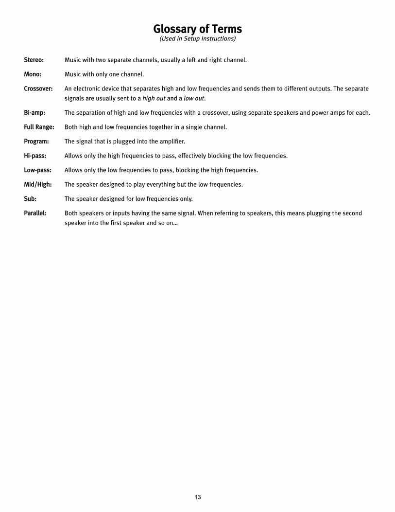
GGlloossssaarryy ooff TTeerrmmss(Used in Setup Instructions)
SStteerreeoo:: Music with two separate channels‚ usually a left and right channel.
MMoonnoo:: Music with only one channel.
CCrroossssoovveerr:: An electronic device that separates high and low frequencies and sends them to different outputs. The separate
signals are usually sent to a high out and a low out.
BBii--aammpp:: The separation of high and low frequencies with a crossover‚ using separate speakers and power amps for each.
FFuullll RRaannggee:: Both high and low frequencies together in a single channel.
PPrrooggrraamm:: The signal that is plugged into the amplifier.
HHii--ppaassss:: Allows only the high frequencies to pass‚ effectively blocking the low frequencies.
LLooww--ppaassss:: Allows only the low frequencies to pass, blocking the high frequencies.
MMiidd//HHiigghh:: The speaker designed to play everything but the low frequencies.
SSuubb:: The speaker designed for low frequencies only.
PPaarraalllleell:: Both speakers or inputs having the same signal. When referring to speakers‚ this means plugging the second
speaker into the first speaker and so on…
14
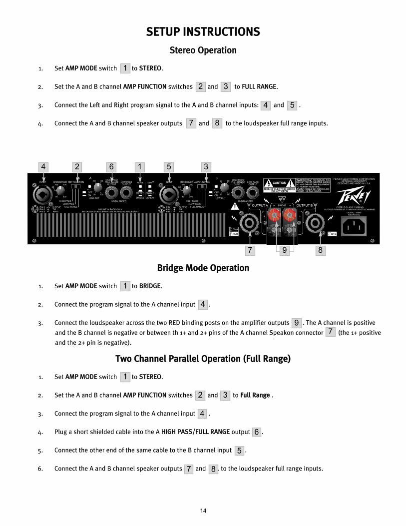
SSEETTUUPP IINNSSTTRRUUCCTTIIOONNSS
SStteerreeoo OOppeerraattiioonn
1. Set AAMMPP MMOODDEE switch to SSTTEERREEOO.
2. Set the A and B channel AAMMPP FFUUNNCCTTIIOONN switches and to FFUULLLL RRAANNGGEE.
3. Connect the Left and Right program signal to the A and B channel inputs: and .
4. Connect the A and B channel speaker outputs and to the loudspeaker full range inputs.
1
2 3
4 5
7 8
BBrriiddggee MMooddee OOppeerraattiioonn
1. Set AAMMPP MMOODDEE switch to BBRRIIDDGGEE.
2. Connect the program signal to the A channel input .
3. Connect the loudspeaker across the two RED binding posts on the amplifier outputs . The A channel is positive
and the B channel is negative or between th 1+ and 2+ pins of the A channel Speakon connector (the 1+ positive
and the 2+ pin is negative).
1
4
97
TTwwoo CChhaannnneell PPaarraalllleell OOppeerraattiioonn ((FFuullll RRaannggee))
1. Set AAMMPP MMOODDEE switch to SSTTEERREEOO.
2. Set the A and B channel AAMMPP FFUUNNCCTTIIOONN switches and to FFuullll RRaannggee .
3. Connect the program signal to the A channel input .
4. Plug a short shielded cable into the A HHIIGGHH PPAASSSS//FFUULLLL RRAANNGGEE output .
5. Connect the other end of the same cable to the B channel input .
6. Connect the A and B channel speaker outputs and . to the loudspeaker full range inputs.
1
2 3
4
6
5
7 8
4 2 6
87 9
1 5 3
15
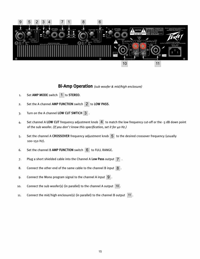
BBii--AAmmpp OOppeerraattiioonn (sub woofer & mid/high enclosure)
1. Set AAMMPP MMOODDEE switch to SSTTEERREEOO.
2. Set the A channel AAMMPP FFUUNNCCTTIIOONN switch to LLOOWW PPAASSSS.
3. Turn on the A channel LLOOWW CCUUTT SSWWTTIICCHH .
4. Set channel A LLOOWW CCUUTT frequency adjustment knob to match the low frequency cut-off or the -3 dB down point
of the sub woofer. (If you don’t know this specification‚ set it for 40 Hz.)
5. Set the channel A CCRROOSSSSOOVVEERR frequency adjustment knob to the desired crossover frequency (usually
100–150 Hz).
6. Set the channel B AAMMPP FFUUNNCCTTIIOONN switch to FULL RANGE.
7. Plug a short shielded cable into the Channel A LLooww PPaassss output .
8. Connect the other end of the same cable to the channel B input .
9. Connect the Mono program signal to the channel A input .
10. Connect the sub woofer(s) (in parallel) to the channel A output .
11. Connect the mid/high enclosure(s) (in parallel) to the channel B output .
1
9
2
4
5
6
7
8
9
10
11
3
5 3 4 7 1 8 6
10 11
2
16
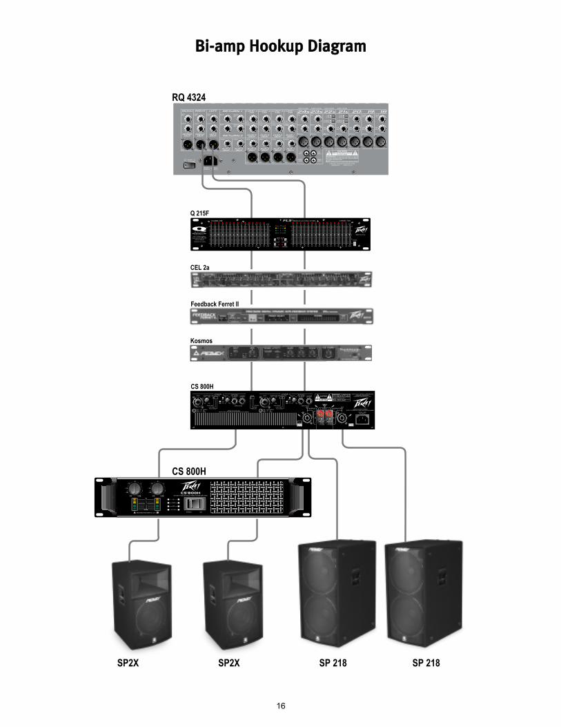
RQ 4324
Q 215F
CS 800H
SP2X SP2X SP 218 SP 218
CEL 2a
Feedback Ferret II
Kosmos
CS 800H
BBii--aammpp HHooookkuupp DDiiaaggrraamm
17
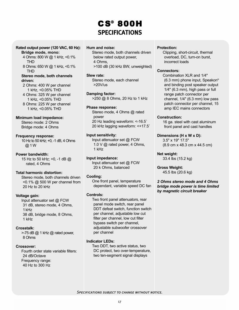
Rated output power (120 VAC, 60 Hz):Bridge mode, mono:4 Ohms: 800 W @ 1 kHz, <0.1%
THD8 Ohms: 650 W @ 1 kHz, <0.1%
THDStereo mode, both channelsdriven:2 Ohms: 400 W per channel
1 kHz, <0.05% THD4 Ohms: 325 W per channel
1 kHz, <0.05% THD8 Ohms: 225 W per channel
1 kHz, <0.05% THD
Minimum load impedance:Stereo mode: 2 OhmsBridge mode: 4 Ohms
Frequency response:10 Hz to 50 kHz; +0‚ -1 dB, 4 Ohms
@ 1 W
Power bandwidth:15 Hz to 50 kHz; +0‚ -1 dB @
rated, 4 Ohms
Total harmonic distortion:Stereo mode, both channels driven<0.1% @ 500 W per channel from 20 Hz to 20 kHz
Voltage gain:Input attenuator set @ FCW 31 dB, stereo mode, 4 Ohms,1 kHz 38 dB, bridge mode, 8 Ohms, 1 kHz
Crosstalk:>-75 dB @ 1 kHz @ rated power, 8 Ohms
Crossover:Fourth order state variable filters: 24 dB/Octave
Frequency range:40 Hz to 300 Hz
Hum and noise:Stereo mode, both channels drivenbelow rated output power, 4 Ohms, >100 dB (30 kHz BW, unweighted)
Slew rate:Stereo mode, each channel>20V/us
Damping factor:>250 @ 8 Ohms, 20 Hz to 1 kHz
Phase response:Stereo mode, 4 Ohms @ rated power
20 Hz leading waveform: <-16.5˚20 kHz lagging waveform: <+17.5˚
Input sensitivity:Input attenuator set @ FCW1.0 V @ rated power, 4 Ohms, 1 kHz
Input impedance:Input attenuator set @ FCW20 k Ohms, balanced
Cooling:One front panel, temperature dependant, variable speed DC fan
Controls:Two front panel attenuators‚ rear panel mode switch‚ rear panelDDT defeat switch, function switchper channel, adjustable low cutfilter per channel, low cut filterbypass switch per channel,adjustable subwoofer crossoverper channel
Indicator LEDs:Two DDT, two active status, two DC protect, two over-temperature,two ten-segment signal displays
Protection:Clipping, short-circuit, thermal overload, DC, turn-on burst,incorrect loads
Connectors:Combination XLR and 1/4" (6.3 mm) phone input, Speakon®
and binding post speaker output1/4" (6.3 mm), high pass or fullrange patch connector perchannel, 1/4" (6.3 mm) low passpatch connector per channel, 15amp IEC mains connectors
Construction:16 ga. steel with cast aluminum front panel and cast handles
Dimensions (H x W x D):3.5" x 19" 17.5"(8.9 cm x 48.3 cm x 44.5 cm)
Net weight:33.4 lbs (15.2 kg)
Gross Weight:45.5 lbs (20.6 kg)
2 Ohms stereo mode and 4 Ohmsbridge mode power is time limitedby magnetic circuit breaker
CS®® 800HSSPPEECCIIFFIICCAATTIIOONNSS
Specifications subject to change without notice.
18
DDEEUUTTSSCCHH
MMeerrkkmmaallee
BBeesscchhrreeiibbuunnggCCSS 880000HH VVeerrssttäärrkkeerr
Wir beglückwünschen Sie dazu, dass Sie sich für den CS 800H Verstärker von Peavey entschieden
haben – er wurde für jahrelangen zuverlässigen und störungsfreien Einsatz unter harten Bedingungen
entwickelt. Dieser Verstärker zeichnet sich durch die überragende Schallleistung und die einzigartige
Zuverlässigkeit aus, für die Peavey bekannt ist. Gleichzeitig ist er überraschend kompakt.
Fortschrittliche Technologie und umfassende Schutzschaltungen ermöglichen einen effizienteren
Betrieb auch bei problematischen Lasten und Energiebedingungen. Die DDT™- (Distortion Detection)
Schaltung gewährleistet einen störungsfreien Betrieb auch bei niedrigen Lasten bis zu 2 Ohm. Die
DDT-Schaltung schützt die Treiber und sorgt dafür, das die Schallleistung selbst unter extremer
Überlastung nicht beeinträchtigt wird. Peaveys Hochleistungskonstruktion arbeitet mit
tunnelgekühlten Kühlkörpern und Gleichstromventilatoren mit variabler Drehzahl. Aufgrund dieser
Kühlmethode wird eine niedrigere Gesamtbetriebstemperatur ermöglicht, was wiederum die
Lebensdauer des Endstufen-Transistors verlängert.
Obwohl der CS 800H Verstärker von Peavey einfach im Betrieb ist und in ultrarobusten Stahlgehäusen
untergebracht ist, birgt sein unsachgemäßer Einsatz Gefahren. Das Gerät ist ein
Hochleistungsverstärker, der hohe Spannungen und Ströme mit Frequenzen bis zu 30 kHz abgibt.
Achten Sie beim Einsatz dieses Verstärkers immer auf sichere Betriebsverfahren.
LLEESSEENN SSIIEE SSIICCHH BBIITTTTEE DDIIEE AABBSSCCHHNNIITTTTEE ÜÜBBEERR WWIICCHHTTIIGGEE SSIICCHHEERRHHEEIITTSSHHIINNWWEEIISSEE SSOOWWIIEE ÜÜBBEERR
EEIINNGGAANNGG,, AAUUSSGGAANNGG UUNNDD SSTTRROOMMAANNSSCCHHLLUUSSSS DDUURRCCHH,, UUMM IIHHRREE SSIICCHHEERRHHEEIITT ZZUU GGEEWWÄÄHHRRLLEEIISSTTEENN..
·· 1199"",, zzwweeii RRaacckk--HHööhheenn,, ffüürr RRaacckk--IInnssttaallllaattiioonn ggeeeeiiggnneett
·· PPaatteennttiieerrttee TTuurrbboo--VV--ggeekküühhllttee KKüühhllkköörrppeerr mmiitt GGlleeiicchhssttrroommllüüfftteerr mmiitt vvaarriiaabblleerr DDrreehhzzaahhll
·· UUllttrraarroobbuusstteess SSttaahhllggeehhääuussee
·· RRaammppUUpp™™--SSiiggnnaallrreeggeelluunngg
·· BBeettrriieebbssaarrtteenn SStteerreeoo ooddeerr BBrriiddggeedd--MMoonnoo
·· WWeecchhsseellssttrroomm--NNeettzzsscchhaalltteerr bbzzww.. --SSiicchheerruunnggssaauuttoommaatt aauuff ddeerr VVoorrddeerrsseeiittee
·· VVeerrssttäärrkkeerrffuunnkkttiioonnsssscchhaalltteerr ffüürr FFuullll--RRaannggee--BBeettrriieebb ooddeerr FFrreeqquueennzzwweeiicchheenn--HHoocchhffrreeqquueennzz-- bbzzww..
NNiieeddeerrffrreeqquueennzz--AAuussggäännggee
·· ZZwweeii uunnaabbhhäännggiiggee jjuussttiieerrbbaarree FFrreeqquueennzzwweeiicchheenn
·· ZZwweeii uunnaabbhhäännggiiggee NNiieeddeerrffrreeqquueennzzffiilltteerr
·· FFüünnff LLEEDD--AAnnzzeeiiggeenn pprroo KKaannaall aauuff ddeerr VVoorrddeerrsseeiittee:: AACCTTIIVVEE,, DDDDTT™™,, SSIIGGNNAALL‚‚ TTEEMMPP uunndd DDCC
AAuussppaacckkeenn
Untersuchen Sie den Verstärker beim Auspacken. Sollten Sie Beschädigungen feststellen, informieren
Sie unverzüglich Ihren Händler. Nur der Empfänger kann gegenüber dem Spediteur einen Anspruch
aufgrund von Transportschäden geltend machen. Heben Sie den Karton und sämtliches
Verpackungsmaterial bitte auf. Sollte es irgendwann einmal erforderlich sein, das Gerät zu Peavey
Electronics oder zu einem unserer Büros, Service-Center oder Händler zurückzuschicken, verwenden
Sie dazu bitte ausschließlich die Original-Werksverpackung. Sollte keine Versandverpackung mehr
vorhanden sein, bitten Sie Peavey um Ersatz.
MMoonnttaaggee
Der CS 800H Verstärker wird in genormten 19"-Racks montiert. Zur zusätzlichen Verstärkung sind
Montageösen auf der Rückseite angebracht; dies wird für vorübergehende Installationen wie etwa
mobile oder Tour-Beschallungssysteme empfohlen. Aufgrund der Kabel und Anschlüsse auf der
Rückseite wird die Befestigung der hinteren Montageösen an den Schienen durch einen
rechtwinkligen Schraubendreher, einen Winkelschraubendreher oder einen Sechskantschlüssel
erleichtert.
19
KKüühhllaannffoorrddeerruunnggeenn
Der CS 800H Verstärker arbeitet mit einem Fremdkühlsystem, das eine niedrige gleichmäßige
Betriebstemperatur gewährleistet. Luft wird durch die Ventilatoren auf der Vorderseite in den
Verstärker eingesaugt, läuft durch die Kühlrippen der tunnelartigen Kanalkühlkörper und wird durch
die seitlichen und rückseitigen Schlitze wieder abgegeben. Wird einer der Kühlkörper zu heiß, öffnet
seine Sensorschaltung das Ausgangsrelais, wodurch die Last von diesem jeweiligen Kanal abgetrennt
wird. Auf der Rückseite des Verstärkers muss eine Abluftöffnung vorhanden sein, und um den
Verstärker herum muss genügend Platz belassen werden, damit die Kühlluft entweichen kann. Wird
der Verstärker im Rack montiert, darf das Rack vorne nicht mit Türen oder Abdeckungen verschlossen
werden; die Zuluft muss unbehindert strömen können. Werden Racks mit verschlossenen Rückseiten
verwendet, muss eine (1) Standard-Rackhöhe für je drei montierte Verstärker offen gelassen werden.
SSiicchheerrhheeiittsshhiinnwweeiissee ffüürr ddeenn BBeettrriieebb
Achten Sie darauf, dass die Netzspannung korrekt ist und mit den Angaben auf der Rückseite des
Verstärkers übereinstimmt. Schäden, die aufgrund des Anschlusses des Verstärkers an eine
ungeeignete Wechselspannung entstehen, werden nicht von der Garantie abgedeckt. Nähere
Informationen zur erforderlichen Spannung finden Sie im Abschnitt Netzanschluss.
Hinweis: Schalten Sie den Verstärker immer aus und trennen Sie ihn vom Netz, bevor Sie Audio-
Geräte anschließen. Als zusätzliche Vorsichtsmaßnahme sollten Sie während des Einschaltens die
Dämpfer herunterdrehen.
Der CS 800H Verstärker ist zwar mit der RampUp™-Schaltung ausgestattet, die den Signalpegel nach
dem Schließen des Ausgangsrelais allmählich anhebt, es empfiehlt sich jedoch, die Gain-Regler
während des Einschaltens heruntergedreht zu lassen, um eine Beschädigung der Lautsprecher zu
verhindern, wenn an den Eingängen ein hoher Signalpegel vorliegt. Ganz gleich, ob Sie sie kaufen
oder selber herstellen, verwenden Sie nur Anschlüsse, Eingangskabel und Lautsprecherkabel guter
Qualität, und gehen Sie beim Löten sorgfältig und korrekt vor, um einen störungsfreien Betrieb zu
gewährleisten. Die meisten Probleme durch Ausfälle werden durch defekte Kabel verursacht.
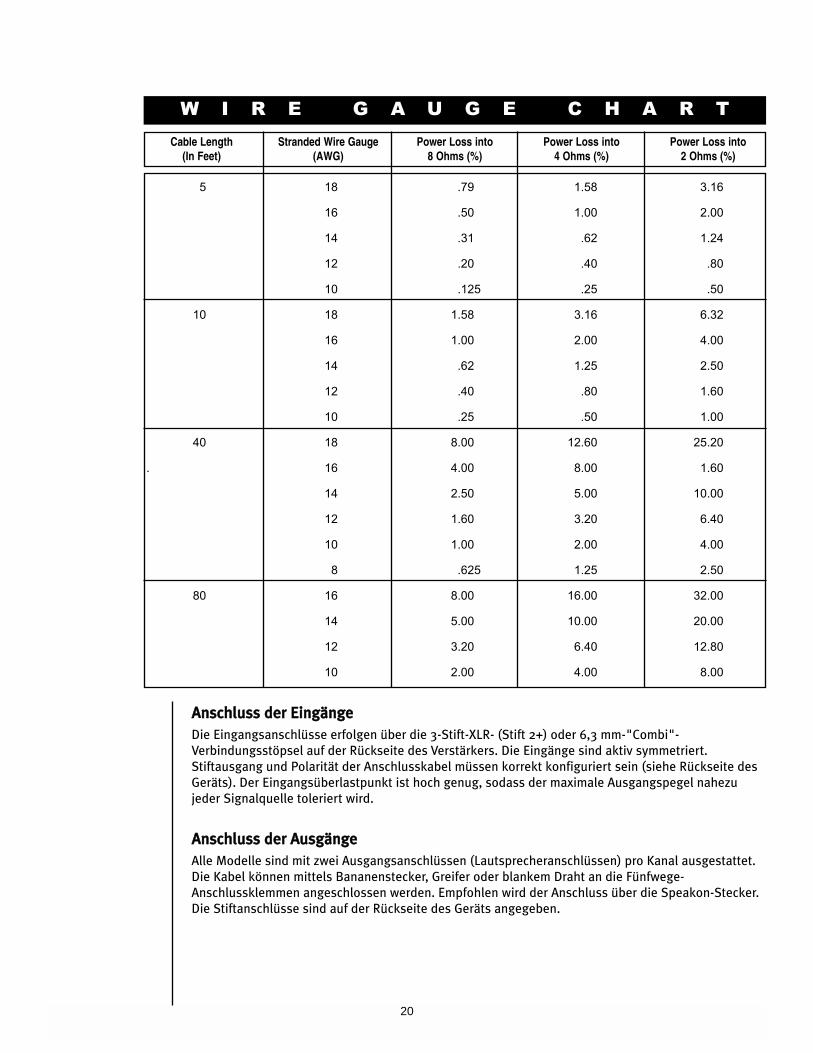
Die geeigneten Durchmesser für verschiedene Lastimpedanzen und Kabellängen finden Sie in der
untenstehenden Kabelstärkentabelle. Denken Sie daran, dass der Kabelwiderstand die Leistung des
Verstärkers auf zweifache Weise beeinträchtigt: Durch direkten Leistungsverlust aufgrund des
Widerstands (I2R-Verlust) und durch Verringerung der Gesamtlastimpedanz. Achten Sie zudem
darauf, dass der Modusschalter für die gewünschte Anwendung korrekt eingestellt ist. Näheres dazu
finden Sie in den Abschnitten Stereo-, Parallel- und Bridged-Mono-Betrieb.
20
W I R E G A U G E C H A R T
Cable Length(In Feet)
Stranded Wire Gauge(AWG)
Power Loss into 8 Ohms (%)
Power Loss into 4 Ohms (%)
Power Loss into 2 Ohms (%)
5 18 .79 1.58 3.16
16 .50 1.00 2.00
14 .31 .62 1.24
12 .20 .40 .80
10 .125 .25 .50
10 18 1.58 3.16 6.32
16 1.00 2.00 4.00
14 .62 1.25 2.50
12 .40 .80 1.60
10 .25 .50 1.00
40 18 8.00 12.60 25.20
. 16 4.00 8.00 1.60
14 2.50 5.00 10.00
12 1.60 3.20 6.40
10 1.00 2.00 4.00
8 .625 1.25 2.50
80 16 8.00 16.00 32.00
14 5.00 10.00 20.00
12 3.20 6.40 12.80
10 2.00 4.00 8.00
AAnnsscchhlluussss ddeerr EEiinnggäännggee
Die Eingangsanschlüsse erfolgen über die 3-Stift-XLR- (Stift 2+) oder 6,3 mm-"Combi"-
Verbindungsstöpsel auf der Rückseite des Verstärkers. Die Eingänge sind aktiv symmetriert.
Stiftausgang und Polarität der Anschlusskabel müssen korrekt konfiguriert sein (siehe Rückseite des
Geräts). Der Eingangsüberlastpunkt ist hoch genug, sodass der maximale Ausgangspegel nahezu
jeder Signalquelle toleriert wird.
AAnnsscchhlluussss ddeerr AAuussggäännggee
Alle Modelle sind mit zwei Ausgangsanschlüssen (Lautsprecheranschlüssen) pro Kanal ausgestattet.
Die Kabel können mittels Bananenstecker, Greifer oder blankem Draht an die Fünfwege-
Anschlussklemmen angeschlossen werden. Empfohlen wird der Anschluss über die Speakon-Stecker.
Die Stiftanschlüsse sind auf der Rückseite des Geräts angegeben.
21
NNeettzzaannsscchhlluussss
Der Leistungsbedarf des CS 800H Verstärkers ist auf 1/8 (übliche Musikbedingungen) und 1/3
(extreme Musikbedingungen) ausgelegt. Der Nennwert der Starkstromaufnahme wird nur über den
Sicherungsautomaten auf der Vorderseite begrenzt. Den Leistungsbedarf des Verstärkers können Sie
den technischen Daten in dieser Anleitung entnehmen. Achten Sie darauf, dass die Netzspannung
korrekt ist und mit den Angaben auf der Rückseite des Verstärkers übereinstimmt. Schäden, die
aufgrund des Anschlusses des Verstärkers an eine ungeeignete Wechselspannung entstehen, werden
nicht von der Garantie abgedeckt. Wenn bei Bestellung nicht anders angegeben, werden die an die
Kunden versandten Peavey-Verstärker folgendermaßen konfiguriert:
Nordamerika: 120 VAC/60 Hz
Europa, Asien, Australien: 230/240 VAC/50 Hz
Südamerika: 120 VAC/60 Hz oder 240 VAC/50 Hz
SStteerreeoo
Für Stereobetrieb (mit zwei Kanälen) schalten Sie den Verstärker aus und stellen den
Moduswahlschalter auf die Position Stereo. In diesem Modus arbeiten beide Kanäle unabhängig
voneinander, wobei ihre jeweiligen Pegel über die Eingangsdämpfer geregelt werden. Ein Signal am
Eingang von Kanal A erzeugt somit ein verstärktes Signal am Ausgang von Kanal A, während ein
Signal am Eingang von Kanal B ein verstärktes Signal am Ausgang von Kanal B erzeugt.
BBrriiddggeedd--MMoodduuss
Beide Verstärkerkanäle können überbrückt werden, um einen äußerst leistungsfähigen Mono-
Verstärker mit einem Kanal einzurichten. Gehen Sie beim Betrieb im Bridged-Modus mit äußerster
Vorsicht vor, da an den Ausgangsklemmen hohe Spannung vorliegen kann. Zum Überbrücken des
Verstärkers stellen Sie den Moduswahlschalter auf der Rückseite auf die Position Bridge. Schließen
Sie das Signal an den Eingang von Kanal A an (alle Eingangsfunktionen von Kanal B sind deaktiviert),
und schließen Sie die Lautsprecher über die spannungsführenden Ausgänge (die Anschlussklemmen
„+" von Kanal A und B) oder zwischen die Stifte 1+ und 2+ des Speakon®-Steckers von Kanal A an.
Der Eingangspegelregler für Kanal A ist der Master-Regler für den Eingangspegel, der Pegelregler für
Kanal B ist deaktiviert. Die Active-LED für den Kanal B leuchtet nicht, sodass sich leicht feststellen
lässt, ob sich der Verstärker im Bridged-Modus befindet.
Anders als beim Stereo-Modus, bei dem eine Seite jedes Ausgangs geerdet ist, sind im Bridged-
Modus beide Seiten spannungsführend. Wird eine Ausgangsschalttafel verwendet, müssen alle
Anschlüsse voneinander und von der Schalttafel isoliert werden. Die empfohlene
Mindestnennlastimpedanz im Bridged-Modus beträgt 4 Ohm (was dem Betrieb beider Kanäle bei 2
Ohm entspricht). Durch das Treiben gebrückter Lasten von unter 4 Ohm wird die LFC-Schaltung (Load
Fault Correction) zur Behebung von Fehllasten aktiviert, was zu einem Leistungsverlust führt und eine
Wärmeüberlastung zur Folge haben kann.
BBeettrriieebbssmmooddii
22
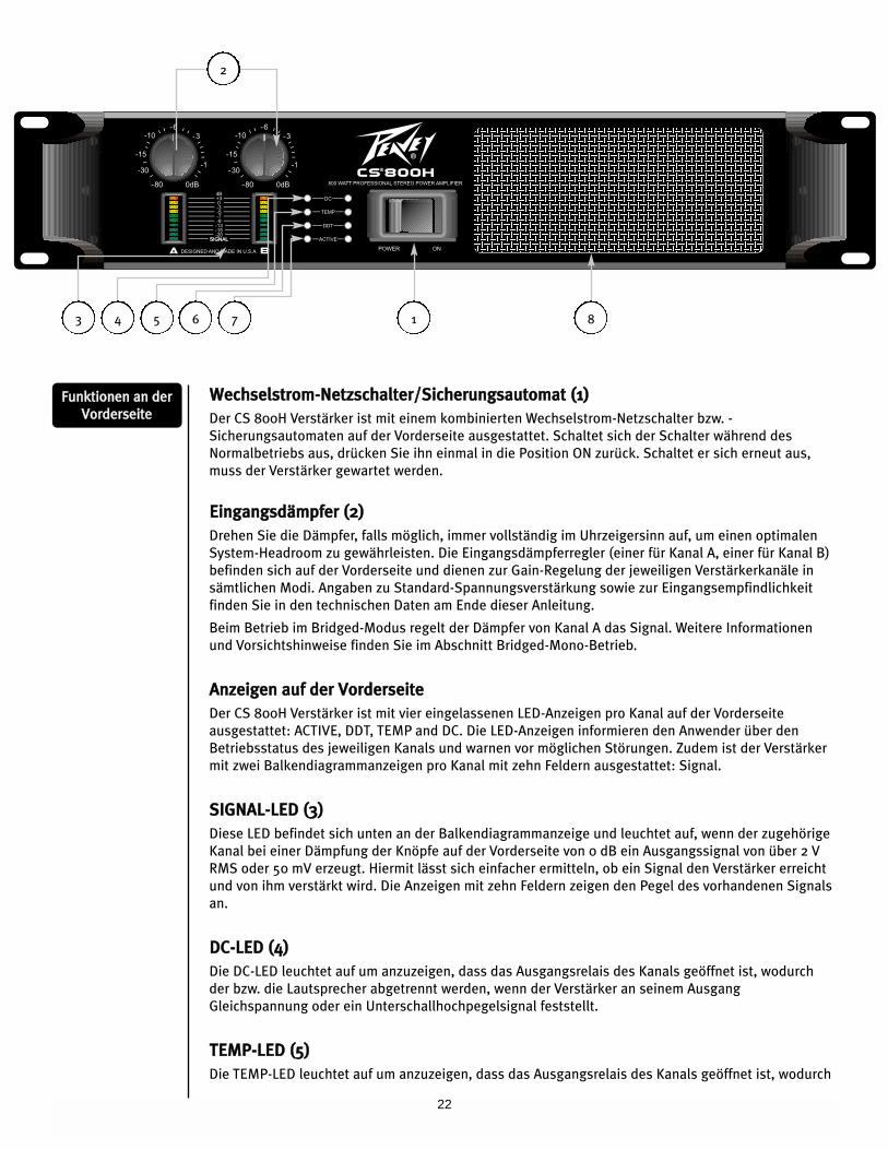
WWeecchhsseellssttrroomm--NNeettzzsscchhaalltteerr//SSiicchheerruunnggssaauuttoommaatt ((11))
Der CS 800H Verstärker ist mit einem kombinierten Wechselstrom-Netzschalter bzw. -
Sicherungsautomaten auf der Vorderseite ausgestattet. Schaltet sich der Schalter während des
Normalbetriebs aus, drücken Sie ihn einmal in die Position ON zurück. Schaltet er sich erneut aus,
muss der Verstärker gewartet werden.
EEiinnggaannggssddäämmppffeerr ((22))
Drehen Sie die Dämpfer, falls möglich, immer vollständig im Uhrzeigersinn auf, um einen optimalen
System-Headroom zu gewährleisten. Die Eingangsdämpferregler (einer für Kanal A, einer für Kanal B)
befinden sich auf der Vorderseite und dienen zur Gain-Regelung der jeweiligen Verstärkerkanäle in
sämtlichen Modi. Angaben zu Standard-Spannungsverstärkung sowie zur Eingangsempfindlichkeit
finden Sie in den technischen Daten am Ende dieser Anleitung.
Beim Betrieb im Bridged-Modus regelt der Dämpfer von Kanal A das Signal. Weitere Informationen
und Vorsichtshinweise finden Sie im Abschnitt Bridged-Mono-Betrieb.
AAnnzzeeiiggeenn aauuff ddeerr VVoorrddeerrsseeiittee
Der CS 800H Verstärker ist mit vier eingelassenen LED-Anzeigen pro Kanal auf der Vorderseite
ausgestattet: ACTIVE, DDT, TEMP and DC. Die LED-Anzeigen informieren den Anwender über den
Betriebsstatus des jeweiligen Kanals und warnen vor möglichen Störungen. Zudem ist der Verstärker
mit zwei Balkendiagrammanzeigen pro Kanal mit zehn Feldern ausgestattet: Signal.
SSIIGGNNAALL--LLEEDD ((33))
Diese LED befindet sich unten an der Balkendiagrammanzeige und leuchtet auf, wenn der zugehörige
Kanal bei einer Dämpfung der Knöpfe auf der Vorderseite von 0 dB ein Ausgangssignal von über 2 V
RMS oder 50 mV erzeugt. Hiermit lässt sich einfacher ermitteln, ob ein Signal den Verstärker erreicht
und von ihm verstärkt wird. Die Anzeigen mit zehn Feldern zeigen den Pegel des vorhandenen Signals
an.
DDCC--LLEEDD ((44))
Die DC-LED leuchtet auf um anzuzeigen, dass das Ausgangsrelais des Kanals geöffnet ist, wodurch
der bzw. die Lautsprecher abgetrennt werden, wenn der Verstärker an seinem Ausgang
Gleichspannung oder ein Unterschallhochpegelsignal feststellt.
TTEEMMPP--LLEEDD ((55))
Die TEMP-LED leuchtet auf um anzuzeigen, dass das Ausgangsrelais des Kanals geöffnet ist, wodurch
FFuunnkkttiioonneenn aann ddeerr
VVoorrddeerrsseeiittee
2
1 84 5 6 73
23
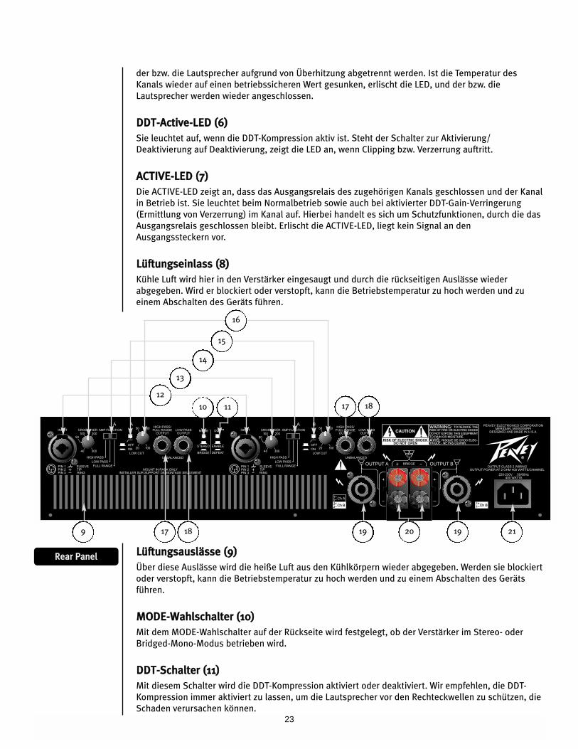
der bzw. die Lautsprecher aufgrund von Überhitzung abgetrennt werden. Ist die Temperatur des
Kanals wieder auf einen betriebssicheren Wert gesunken, erlischt die LED, und der bzw. die
Lautsprecher werden wieder angeschlossen.
DDDDTT--AAccttiivvee--LLEEDD ((66))
Sie leuchtet auf, wenn die DDT-Kompression aktiv ist. Steht der Schalter zur Aktivierung/
Deaktivierung auf Deaktivierung, zeigt die LED an, wenn Clipping bzw. Verzerrung auftritt.
AACCTTIIVVEE--LLEEDD ((77))
Die ACTIVE-LED zeigt an, dass das Ausgangsrelais des zugehörigen Kanals geschlossen und der Kanal
in Betrieb ist. Sie leuchtet beim Normalbetrieb sowie auch bei aktivierter DDT-Gain-Verringerung
(Ermittlung von Verzerrung) im Kanal auf. Hierbei handelt es sich um Schutzfunktionen, durch die das
Ausgangsrelais geschlossen bleibt. Erlischt die ACTIVE-LED, liegt kein Signal an den
Ausgangssteckern vor.
LLüüffttuunnggsseeiinnllaassss ((88))
Kühle Luft wird hier in den Verstärker eingesaugt und durch die rückseitigen Auslässe wieder
abgegeben. Wird er blockiert oder verstopft, kann die Betriebstemperatur zu hoch werden und zu
einem Abschalten des Geräts führen.
RReeaarr PPaanneell LLüüffttuunnggssaauusslläässssee ((99))
Über diese Auslässe wird die heiße Luft aus den Kühlkörpern wieder abgegeben. Werden sie blockiert
oder verstopft, kann die Betriebstemperatur zu hoch werden und zu einem Abschalten des Geräts
führen.
MMOODDEE--WWaahhllsscchhaalltteerr ((1100))
Mit dem MODE-Wahlschalter auf der Rückseite wird festgelegt, ob der Verstärker im Stereo- oder
Bridged-Mono-Modus betrieben wird.
DDDDTT--SScchhaalltteerr ((1111))
Mit diesem Schalter wird die DDT-Kompression aktiviert oder deaktiviert. Wir empfehlen, die DDT-
Kompression immer aktiviert zu lassen, um die Lautsprecher vor den Rechteckwellen zu schützen, die
Schaden verursachen können.
12
10 11
17 18 19 19 2120
17 18
9
13
14
15
16
24
KKaannaalleeiinnggaanngg ((1122))
Dieser Eingang ist mit einem Combo-Stecker ausgestattet, der für einen herkömmlichen dreipoligen
männlichen XLR-Stecker, einen 6,3-mm-Klinkenstecker oder einen 6,3-mm- Monostecker geeignet ist.
Daneben steht ein elektronisch symmetrierter Eingang mit XLR- und 6,3-mm-Klinkenanschluss zur
Verfügung. Das Gerät ist intern folgendermaßen verdrahtet:
Input XLR Klinke
(+) Stift 2 Spitze
(-) Stift 3 Ring
Erde Stift 1 Masse
FFrreeqquueennzzwweeiicchheenn--EEiinnsstteellllkknnooppff ((1133))
Der CS 800H ist mit zwei unabhängigen Zweiwegefrequenzweichen ausgestattet, die von 40 Hz bis
300 Hz eingestellt werden können. Diese Überschneidungsfrequenzen eignen sich für den Einsatz mit
einem Subwoofer-System. Der Ausgang dieser Frequenzweichen wird mit dem Amp-Function-Schalter
ausgewählt und an den entsprechenden Verstärkerkanal angeschlossen. Frequenzen über der
Einstellung des Knopfs werden an den jeweiligen Kanal angeschlossen, wenn sich der Amp-Function-
Schalter auf der Position HIGH PASS befindet. Frequenzen unter der Einstellung des Knopfs werden
an den jeweiligen Kanal angeschlossen, wenn sich der Amp-Function-Schalter auf der Position LOW
PASS befindet. Auf der Position FULL RANGE wird die Frequenzweiche umgangen.
AAmmpp--FFuunnccttiioonn--SScchhaalltteerr ((1144))
Mit dem Amp-Function-Wahlschalter auf der Rückseite wird eingestellt, ob der zugehörige Kanal für
den Full-Range-Betrieb oder an die Frequenzweichen-Hochfrequenz- oder -Niederfrequenzausgänge
angeschlossen wird.
LLooww--CCuutt--SScchhaalltteerr ((1155))
Der LOW-CUT-Schalter ist ein eingelassener Druckschalter, mit dem der TIEFPASSFILTER aktiviert oder
deaktiviert wird. Der Filter wird aktiviert, indem der Schalter in die Position IN gedrückt wird.
TTiieeffppaassss--EEiinnsstteellllkknnooppff ((1166))
Der CS 800H ist mit zwei unabhängigen Niederfrequenzfiltern ausgestattet. Diese Filter können von
20 Hz bis 100 Hz eingestellt werden und wurden entwickelt, um Frequenzen zu verringern, die unter
denjenigen liegen, die von den Lautsprechern erzeugt werden können, oder um „Raumbrummen" zu
verringern. Frequenzen unter der Knopfeinstellung des jeweiligen Kanals werden gedämpft.
SStteecckkeerr HHiigghh PPaassss//FFuullll RRaannggee OOuuttppuutt ((1177))
Die Funktion des Steckers HIGH PASS/FULL RANGE OUTPUT hängt von der Einstellung des jeweiligen
Amp-Function-Schalters ab. Dieser Stecker ermöglicht das Anschließen von Frequenzen über der
Einstellung des Crossover-Knopfs an einen zweiten Verstärker. Steht der Amp-Function-Schalter auf
der Position HIGH PASS, liegt der hochfrequente Anteil der Frequenzweiche am Stecker vor. Steht der
Amp-Function-Schalter auf der Position FULL RANGE oder LOW PASS, wird die Frequenzweiche
umgangen, sodass ein Anschluss des Full-Range-Signals an einen zweiten Verstärker möglich ist.
LLooww--PPaassss--OOuuttppuutt--SStteecckkeerr ((1188))
Der LOW-PASS-OUTPUT-Stecker ermöglicht das Anschließen von Frequenzen unter der Einstellung des
Crossover-Knopfs an einen zweiten Verstärker. Dieser Ausgang ist bei niedrigen Frequenzen
unabhängig von der Einstellung des Amp-Function-Schalters.
25
SSppeeaakkoonn®®--AAuussggaannggsssstteecckkeerr ((1199))
Jeder Kanal ist mit einem vieradrigen Speakon-Stecker für den Ausgang ausgestattet. Bei beiden
Kanälen ist der Stift 1+ der Kanalsignalausgang und der Stift 1- die Gehäuseerdung. Beim Stecker von
Kanal A liegt am Stift 2+ der Signalausgang von Kanal B an, und der Stift 2- ist die Gehäuseerdung.
AAnnsscchhlluusssskklleemmmmeenn--AAuussggaannggsssstteecckkeerr ((2200))
Jeder Kanal ist mit einem Paar schutzisolierter Anschlussklemmen ausgestattet, die parallel zum
Speakon-Stecker angeschlossen sind. Die roten Anschlussklemmen sind die Signalausgänge jedes
Kanals, die schwarzen Anschlussklemmen die Gehäuseerdung. Beim Betrieb im Bridged-Modus
werden nur die roten Anschlussklemmen verwendet. Die roten Anschlussklemmen von Kanal A sind
der positive Ausgang des Systems und müssen an den positiven Eingang des zugehörigen
Lautsprechersystems angeschlossen werden.
SStteecckkeerr ddeess WWeecchhsseellssttrroommnneettzzkkaabbeellss ((2211))
Hier wird das abziehbare (IEC-) Wechselstromnetzkabel eingesteckt. Es darf nur an eine geeignete
Stromquelle angeschlossen werden (siehe Markierungen auf der Rückseite).
Der CS 800H ist mit verschiedenen Schaltungen ausgestattet, durch die er selbst und auch die
Lautsprecher in nahezu jeder Situation geschützt werden. Peavey hat versucht, den Verstärker so
narrensicher wie möglich zu machen, und ihn unempfindlich gegenüber Kurzschluss, Leerlauf,
ungeeigneten Lasten, Gleichspannung und Überhitzung gemacht. Schaltet ein Kanal in den DDT-
Modus zur Gain-Verringerung, bleibt die Lautsprecherlast angeschlossen, Clipping-Prozentsatz oder
Ausgangsleistung werden jedoch sofort verringert. Tritt ein Problem auf, das den Schutzmodus eines
Kanals aktiviert, leuchten die TEMP-LED oder DC-LED für diesen Kanal auf. Bei Gleichspannung am
Ausgang, überhöhten Unterschallfrequenzen oder Wärmeüberlastung trennt das Ausgangsrelais des
Kanals die Lautsprecherlast, bis das Problem behoben wird oder der Verstärker abgekühlt ist.
EErrmmiittttlluunngg uunndd BBeeggrreennzzuunngg vvoonn VVeerrzzeerrrruunngg ((DDDDTT))
Peaveys DDT-Kompressionssystem ermöglicht eine maximale Leistung der Kombination
Endstufe/Lautsprecher, denn es gewährleistet, dass immer genügend Headroom zur Verfügung steht,
und verhindert so Clipping. Dieses Kompressionssystem wird durch eine einzigartige Schaltung
aktiviert, die die Signalbedingungen ermittelt, die zu einer Überlastung des Verstärkers führen
können, und es verringert die Kanalverstärkung kurz vor dem Clipping. Die Kompressionsschwelle ist
das Clipping selbst, und es wird keine spezielle Schwellenregelung verwendet. Durch diese Technik
wird jedes der Endstufe zur Verfügung stehende Watt effektiv genutzt, um das Signal wiederzugeben,
während gleichzeitig Clipping und Verzerren verringert werden. Dadurch werden mögliche
Beeinträchtigungen oder Beschädigungen der Lautsprecher deutlich vermindert.
LLFFCC--IImmppeeddaannzzeerrmmiittttlluunngg
Der CS 800H ist mit einer innovativen Schaltung ausgestattet, die einen sicheren Betrieb bei jeder
Last ermöglicht. Liegt an einem Verstärker eine Last vor, die die Endstufe überlastet, korrigiert die
Load-Fault-Correction-Schaltung die Kanalverstärkung auf einen sicheren Pegel. Dieses Verfahren zum
Schutz der Endstufe ist den herkömmlichen Begrenzungsverfahren anderer Verstärker, die mit „roher
Gewalt" arbeiten, weit überlegen. Die LFC-Schaltung beeinträchtigt die Schallleistung im
Normalbetrieb nicht und ist unauffällig, wenn sie aktiviert ist.
TThheerrmmoosscchhuuttzz
Die internen Ventilatoren sorgen dafür, dass der Verstärker unter Normalbedingungen innerhalb
seines Temperaturbereichs störungsfrei arbeitet. Erreicht die Temperatur des Kühlkörpers eines
Kanals o Ausreichende Temperatur, was auf eine gestörte Luftzufuhr hinweisen kann, schützt sich der
SScchhuuttzzffuunnkkttiioonneenn
26
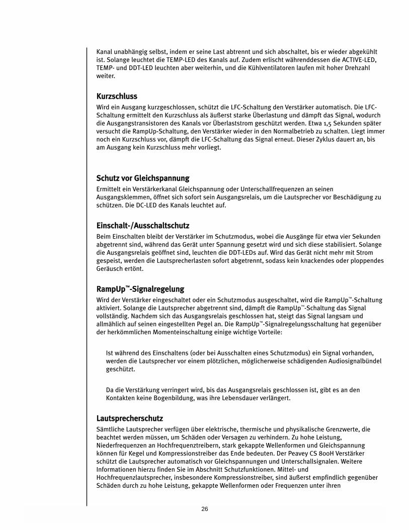
Kanal unabhängig selbst, indem er seine Last abtrennt und sich abschaltet, bis er wieder abgekühlt
ist. Solange leuchtet die TEMP-LED des Kanals auf. Zudem erlischt währenddessen die ACTIVE-LED,
TEMP- und DDT-LED leuchten aber weiterhin, und die Kühlventilatoren laufen mit hoher Drehzahl
weiter.
KKuurrzzsscchhlluussss
Wird ein Ausgang kurzgeschlossen, schützt die LFC-Schaltung den Verstärker automatisch. Die LFC-
Schaltung ermittelt den Kurzschluss als äußerst starke Überlastung und dämpft das Signal, wodurch
die Ausgangstransistoren des Kanals vor Überlaststrom geschützt werden. Etwa 1,5 Sekunden später
versucht die RampUp-Schaltung, den Verstärker wieder in den Normalbetrieb zu schalten. Liegt immer
noch ein Kurzschluss vor, dämpft die LFC-Schaltung das Signal erneut. Dieser Zyklus dauert an, bis
am Ausgang kein Kurzschluss mehr vorliegt.
SScchhuuttzz vvoorr GGlleeiicchhssppaannnnuunngg
Ermittelt ein Verstärkerkanal Gleichspannung oder Unterschallfrequenzen an seinen
Ausgangsklemmen, öffnet sich sofort sein Ausgangsrelais, um die Lautsprecher vor Beschädigung zu
schützen. Die DC-LED des Kanals leuchtet auf.
EEiinnsscchhaalltt--//AAuusssscchhaallttsscchhuuttzz
Beim Einschalten bleibt der Verstärker im Schutzmodus, wobei die Ausgänge für etwa vier Sekunden
abgetrennt sind, während das Gerät unter Spannung gesetzt wird und sich diese stabilisiert. Solange
die Ausgangsrelais geöffnet sind, leuchten die DDT-LEDs auf. Wird das Gerät nicht mehr mit Strom
gespeist, werden die Lautsprecherlasten sofort abgetrennt, sodass kein knackendes oder ploppendes
Geräusch ertönt.
RRaammppUUpp™™--SSiiggnnaallrreeggeelluunngg
Wird der Verstärker eingeschaltet oder ein Schutzmodus ausgeschaltet, wird die RampUp™-Schaltung
aktiviert. Solange die Lautsprecher abgetrennt sind, dämpft die RampUp™-Schaltung das Signal
vollständig. Nachdem sich das Ausgangsrelais geschlossen hat, steigt das Signal langsam und
allmählich auf seinen eingestellten Pegel an. Die RampUp™-Signalregelungsschaltung hat gegenüber
der herkömmlichen Momenteinschaltung einige wichtige Vorteile:
Ist während des Einschaltens (oder bei Ausschalten eines Schutzmodus) ein Signal vorhanden,
werden die Lautsprecher vor einem plötzlichen, möglicherweise schädigenden Audiosignalbündel
geschützt.
Da die Verstärkung verringert wird, bis das Ausgangsrelais geschlossen ist, gibt es an den
Kontakten keine Bogenbildung, was ihre Lebensdauer verlängert.
LLaauuttsspprreecchheerrsscchhuuttzz
Sämtliche Lautsprecher verfügen über elektrische, thermische und physikalische Grenzwerte, die
beachtet werden müssen, um Schäden oder Versagen zu verhindern. Zu hohe Leistung,
Niederfrequenzen an Hochfrequenztreibern, stark gekappte Wellenformen und Gleichspannung
können für Kegel und Kompressionstreiber das Ende bedeuten. Der Peavey CS 800H Verstärker
schützt die Lautsprecher automatisch vor Gleichspannungen und Unterschallsignalen. Weitere
Informationen hierzu finden Sie im Abschnitt Schutzfunktionen. Mittel- und
Hochfrequenzlautsprecher, insbesondere Kompressionstreiber, sind äußerst empfindlich gegenüber
Schäden durch zu hohe Leistung, gekappte Wellenformen oder Frequenzen unter ihren
27
Passbandnennwerten. Achten Sie unbedingt darauf, dass die niedrigen und mittleren Bänder einer elektronischen
Frequenzweiche an die korrekten Verstärker und Treiber und nicht versehentlich an die für ein Band mit niedrigerer Frequenz
angeschlossen werden. Der Clipping-Punkt eines Verstärkers ist seine maximale Spitzenausgangsleistung, und der Peavey CS
800H Hochleistungsverstärker kann eine höhere Leistung bringen, als viele Lautsprecher ohne Schäden bearbeiten können.
Achten Sie darauf, dass das Spitzenleistungsvermögen des Verstärkers Ihr Lautsprechersystem nicht überlastet.
Sicherungen können ebenfalls verwendet werden, um die Leistungszufuhr zu den Lautsprechertreibern zu begrenzen. Als eher
strombegrenzende anstatt spannungsbegrenzende Vorrichtungen sind sie jedoch eine unzureichende Lösung, und als
schwächstes Glied können sie nur einmal eingesetzt werden und müssen dann ausgetauscht werden. Einige Sicherungen
schlechter Qualität verfügen über einen beträchtlichen Reihenwiderstand, der die Dämpfung der Lautsprecherbewegung durch
den Verstärker beeinträchtigen und sogar die Klangqualität des Systems verschlechtern kann. Sollten Sie Sicherungen
einsetzen wollen, erfragen Sie bitte beim Lautsprecherhersteller die geeigneten Stromnennwerte und die erforderliche
Trägheit.
Treiben Sie eine niederfrequente Lautsprecherbox nie mit Frequenzen, die unter ihrer jeweiligen ausgelegten Frequenz liegen.
Aufgrund der verringerten Schalldämpfung könnte eine auf eine bestimmte Resonanz abgestimmte Box selbst bei mäßiger
Leistung völlig absacken. Die Frequenzgrenzen eines Lautsprechersystems finden Sie unter den jeweiligen technischen Daten.
WWaarrttuunngg ddeess VVeerrssttäärrkkeerrss uunndd VVeerraannttwwoorrttuunngg ddeess NNuuttzzeerrss
Eine regelmäßige Wartung des CS 800H Verstärkers ist nicht erforderlich, und eine interne Justierung sollte während seiner
Lebensdauer überflüssig sein. Ihr CS 800H Verstärker ist äußerst leistungsfähig und kann sowohl für Lautsprecher als auch für
Personen Gefahren bergen. Lesen Sie sich als verantwortlicher Nutzer den Abschnitt Wichtige Sicherheitshinweise durch, und
achten Sie darauf, dass Installation, Anschluss und Betrieb des Verstärkers korrekt gemäß den Anweisungen in dieser
Anleitung erfolgen. Viele Lautsprecher werden durch übermäßige Verstärkerleistung beschädigt oder zerstört, was
insbesondere bei den gebrückten Hochleistungsverstärkern der Fall ist. Lesen Sie sich den Abschnitt Lautsprecherschutz durch,
und beachten Sie immer Dauer- und Spitzenleistungsvermögen des Lautsprechers.
28
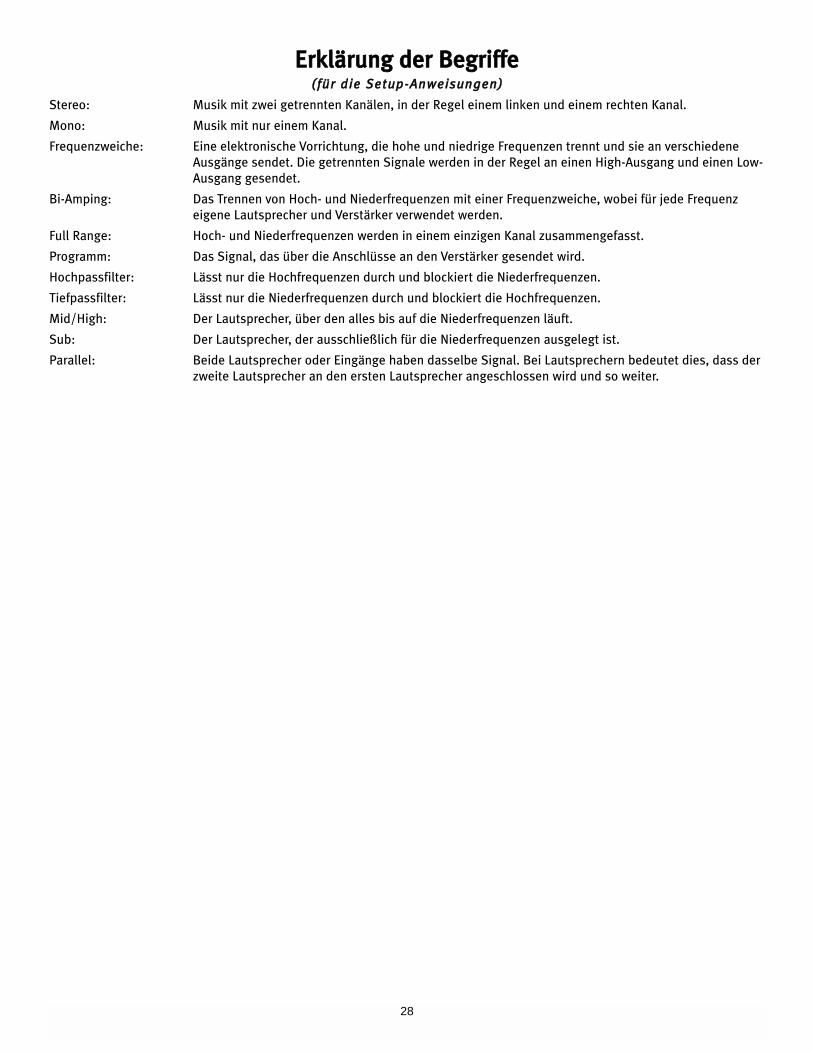
EErrkklläärruunngg ddeerr BBeeggrriiffffee((ffüürr ddiiee SSeettuupp--AAnnwweeiissuunnggeenn))
Stereo: Musik mit zwei getrennten Kanälen, in der Regel einem linken und einem rechten Kanal.
Mono: Musik mit nur einem Kanal.
Frequenzweiche: Eine elektronische Vorrichtung, die hohe und niedrige Frequenzen trennt und sie an verschiedene
Ausgänge sendet. Die getrennten Signale werden in der Regel an einen High-Ausgang und einen Low-
Ausgang gesendet.
Bi-Amping: Das Trennen von Hoch- und Niederfrequenzen mit einer Frequenzweiche, wobei für jede Frequenz
eigene Lautsprecher und Verstärker verwendet werden.
Full Range: Hoch- und Niederfrequenzen werden in einem einzigen Kanal zusammengefasst.
Programm: Das Signal, das über die Anschlüsse an den Verstärker gesendet wird.
Hochpassfilter: Lässt nur die Hochfrequenzen durch und blockiert die Niederfrequenzen.
Tiefpassfilter: Lässt nur die Niederfrequenzen durch und blockiert die Hochfrequenzen.
Mid/High: Der Lautsprecher, über den alles bis auf die Niederfrequenzen läuft.
Sub: Der Lautsprecher, der ausschließlich für die Niederfrequenzen ausgelegt ist.
Parallel: Beide Lautsprecher oder Eingänge haben dasselbe Signal. Bei Lautsprechern bedeutet dies, dass der
zweite Lautsprecher an den ersten Lautsprecher angeschlossen wird und so weiter.
29
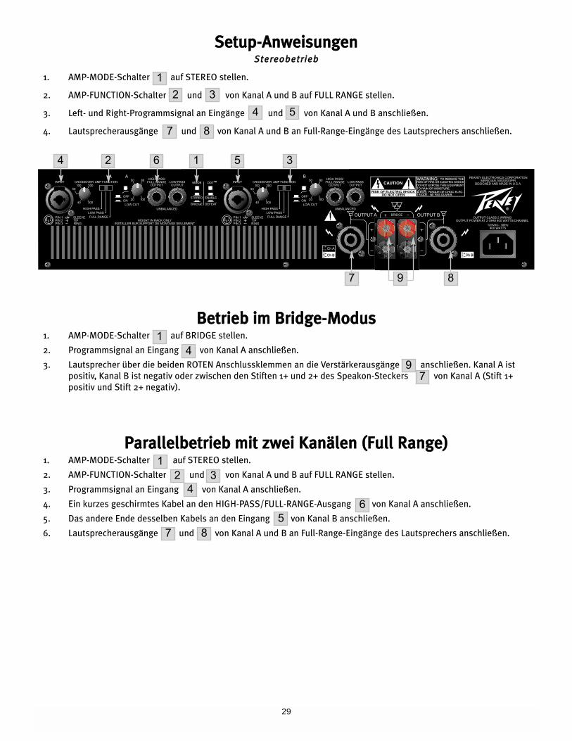
SSeettuupp--AAnnwweeiissuunnggeennSStteerreeoobbeettrriieebb
1. AMP-MODE-Schalter auf STEREO stellen.
2. AMP-FUNCTION-Schalter und von Kanal A und B auf FULL RANGE stellen.
3. Left- und Right-Programmsignal an Eingänge und von Kanal A und B anschließen.
4. Lautsprecherausgänge und von Kanal A und B an Full-Range-Eingänge des Lautsprechers anschließen.
BBeettrriieebb iimm BBrriiddggee--MMoodduuss1. AMP-MODE-Schalter auf BRIDGE stellen.
2. Programmsignal an Eingang von Kanal A anschließen.
3. Lautsprecher über die beiden ROTEN Anschlussklemmen an die Verstärkerausgänge anschließen. Kanal A ist
positiv, Kanal B ist negativ oder zwischen den Stiften 1+ und 2+ des Speakon-Steckers von Kanal A (Stift 1+
positiv und Stift 2+ negativ).
PPaarraalllleellbbeettrriieebb mmiitt zzwweeii KKaannäälleenn ((FFuullll RRaannggee))1. AMP-MODE-Schalter auf STEREO stellen.
2. AMP-FUNCTION-Schalter und von Kanal A und B auf FULL RANGE stellen.
3. Programmsignal an Eingang von Kanal A anschließen.
4. Ein kurzes geschirmtes Kabel an den HIGH-PASS/FULL-RANGE-Ausgang von Kanal A anschließen.
5. Das andere Ende desselben Kabels an den Eingang von Kanal B anschließen.
6. Lautsprecherausgänge und von Kanal A und B an Full-Range-Eingänge des Lautsprechers anschließen.
1
2 3
4 5
7
14
97
12 3
46
57 8
8
4 2 6
87 9
1 5 3
30
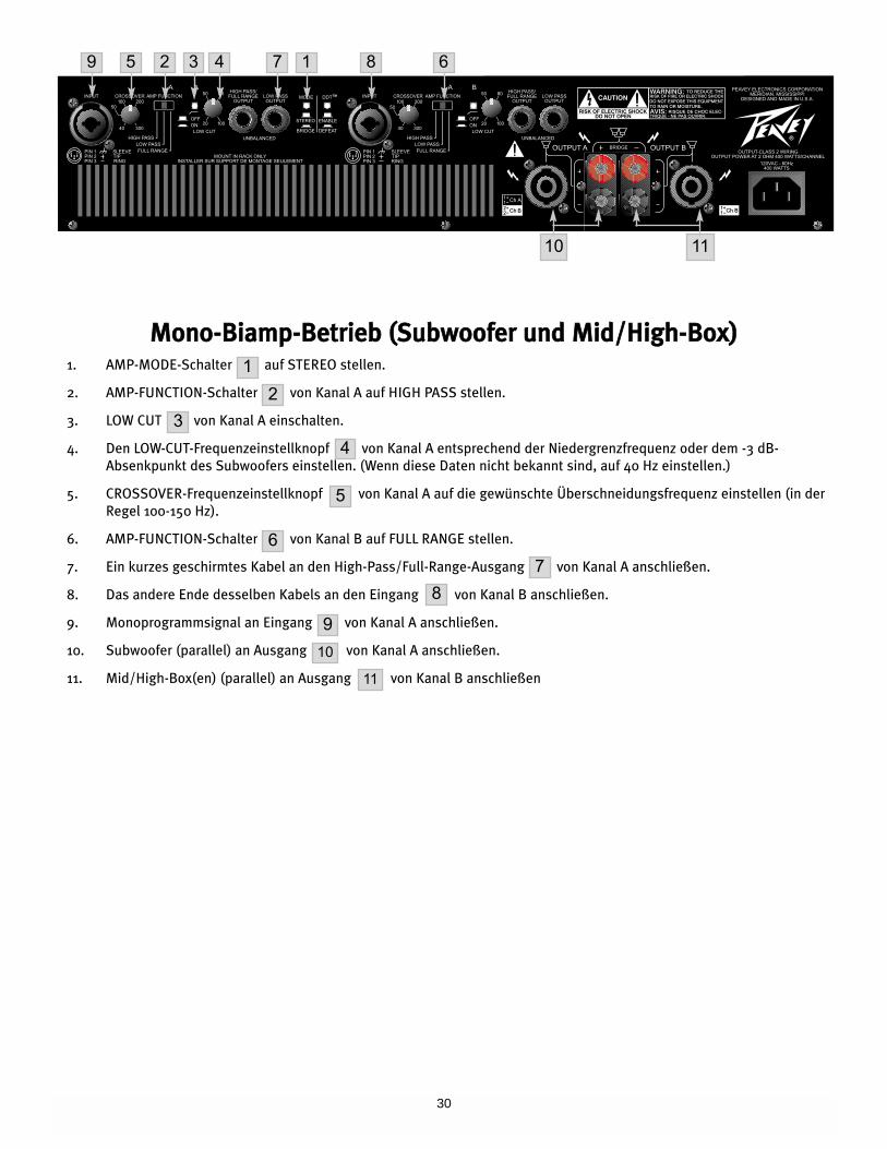
MMoonnoo--BBiiaammpp--BBeettrriieebb ((SSuubbwwooooffeerr uunndd MMiidd//HHiigghh--BBooxx))1. AMP-MODE-Schalter auf STEREO stellen.
2. AMP-FUNCTION-Schalter von Kanal A auf HIGH PASS stellen.
3. LOW CUT von Kanal A einschalten.
4. Den LOW-CUT-Frequenzeinstellknopf von Kanal A entsprechend der Niedergrenzfrequenz oder dem -3 dB-
Absenkpunkt des Subwoofers einstellen. (Wenn diese Daten nicht bekannt sind, auf 40 Hz einstellen.)
5. CROSSOVER-Frequenzeinstellknopf von Kanal A auf die gewünschte Überschneidungsfrequenz einstellen (in der
Regel 100-150 Hz).
6. AMP-FUNCTION-Schalter von Kanal B auf FULL RANGE stellen.
7. Ein kurzes geschirmtes Kabel an den High-Pass/Full-Range-Ausgang von Kanal A anschließen.
8. Das andere Ende desselben Kabels an den Eingang von Kanal B anschließen.
9. Monoprogrammsignal an Eingang von Kanal A anschließen.
10. Subwoofer (parallel) an Ausgang von Kanal A anschließen.
11. Mid/High-Box(en) (parallel) an Ausgang von Kanal B anschließen
9 5 3 4 7 1 8 6
10 11
2
1
2
3
4
5
6
7
8
9
10
11

31
Rated output power (120 VAC, 60 Hz):Bridge mode, mono:4 Ohms: 800 W @ 1 kHz, <0.1%
THD8 Ohms: 650 W @ 1 kHz, <0.1%
THDStereo mode, both channelsdriven:2 Ohms: 400 W per channel
1 kHz, <0.05% THD4 Ohms: 325 W per channel
1 kHz, <0.05% THD8 Ohms: 225 W per channel
1 kHz, <0.05% THD
Minimum load impedance:Stereo mode: 2 OhmsBridge mode: 4 Ohms
Frequency response:10 Hz to 50 kHz; +0‚ -1 dB, 4 Ohms
@ 1 W
Power bandwidth:15 Hz to 50 kHz; +0‚ -1 dB @
rated, 4 Ohms
Total harmonic distortion:Stereo mode, both channels driven<0.1% @ 500 W per channel from 20 Hz to 20 kHz
Voltage gain:Input attenuator set @ FCW 31 dB, stereo mode, 4 Ohms,1 kHz 38 dB, bridge mode, 8 Ohms, 1 kHz
Crosstalk:>-75 dB @ 1 kHz @ rated power, 8 Ohms
Crossover:Fourth order state variable filters: 24 dB/Octave
Frequency range:40 Hz to 300 Hz
Hum and noise:Stereo mode, both channels drivenbelow rated output power, 4 Ohms, >100 dB (30 kHz BW, unweighted)
Slew rate:Stereo mode, each channel>20V/us
Damping factor:>250 @ 8 Ohms, 20 Hz to 1 kHz
Phase response:Stereo mode, 4 Ohms @ rated power
20 Hz leading waveform: <-16.5˚20 kHz lagging waveform: <+17.5˚
Input sensitivity:Input attenuator set @ FCW1.0 V @ rated power, 4 Ohms, 1 kHz
Input impedance:Input attenuator set @ FCW20 k Ohms, balanced
Cooling:One front panel, temperature dependant, variable speed DC fan
Controls:Two front panel attenuators‚ rear panel mode switch‚ rear panelDDT defeat switch, function switchper channel, adjustable low cutfilter per channel, low cut filterbypass switch per channel,adjustable subwoofer crossoverper channel
Indicator LEDs:Two DDT, two active status, two DC protect, two over-temperature,two ten-segment signal displays
Protection:Clipping, short-circuit, thermal overload, DC, turn-on burst,incorrect loads
Connectors:Combination XLR and 1/4" (6.3 mm) phone input, Speakon®
and binding post speaker output1/4" (6.3 mm), high pass or fullrange patch connector perchannel, 1/4" (6.3 mm) low passpatch connector per channel, 15amp IEC mains connectors
Construction:16 ga. steel with cast aluminum front panel and cast handles
Dimensions (H x W x D):3.5" x 19" 17.5"(8.9 cm x 48.3 cm x 44.5 cm)
Net weight:33.4 lbs (15.2 kg)
Gross Weight:45.5 lbs (20.6 kg)
2 Ohms stereo mode and 4 Ohmsbridge mode power is time limitedby magnetic circuit breaker
CS®® 800HSSPPEECCIIFFIICCAATTIIOONNSS
32
EESSPPAAÑÑOOLL
CCaarraacctteerriissttiiccaass
DDeessccrriippttiioonnAAmmpplliiffiiccaaddoorr ddee PPooddeerr CCSS 880000HH
Felicidades en tu compra de un amplificador CS 800H de Peavey, diseñado para brindarte años de
operación confiable bajo el uso más exigente. Este amplificador ofrece superioridad sonora y la
confiabilidad inmejorable que por tanto años ha sido relacionada con Peavey, manteniendo un
tamaño compacto. Tecnología avanzada y extensos circuitos de protección permiten la operación a
gran eficiencia en condiciones no siempre perfectas, y con cargas pesadas. El circuito DDT™
(identificador de distorsión) permite la operación sin problemas en cargas tan bajas como 2 Ohmios.
El circuito identificador de Distorsión protege a los drivers y asegura que se mantiene integridad en el
sonido, aun en condiciones de saturación extrema. El diseño altamente eficiente de Peavey usa
parrillas de calor enfriadas por túneles y ventiladores DC de velocidad variable. Esta topología de
enfriamiento mantiene un promedio de temperatura de operación más bajo, resultando en vida
prolongada de los transistores de salida.
A pesar que el CS 800H de Peavey es muy simple de operar y reside dentro de un chasis ultra-fuerte
de acero, el uso indebido puede ser peligroso. Este es un amplificador de poder muy alto que puede
producir voltajes altos y corrientes considerables de hasta 30 kHz. Siempre hay que ejercer técnicas
de operación seguras con este amplificador.
PPAARRAA TTUU SSEEGGUURRIIDDAADD,, LLEEEE LLAA SSEECCCCIIÓÓNN DDEE PPRREECCAAUUCCIIOONNEESS,, AASSII CCOOMMOO LLAASS DDEE SSAALLIIDDAA,, EENNTTRRAADDAA YY
CCOONNEEXXIIOONNEESS DDEE CCOORRRRIIEENNTTEE..
·· DDiisseeññoo ddee rraacckk ddee ddooss eessppaacciiooss yy 1199""
·· PPaarrrriillllaass ddee ccaalloorr eennffrriiaaddaass ppoorr vveennttiillaaddoorreess DDCC ddee vveelloocciiddaadd vvaarriiaabbllee
·· CChhaassiiss ddee aacceerroo ddee ccoonnssttrruucccciióónn ffuueerrttee
·· CCoonnttrrooll ddee sseeññaall RRaammppUUpp™™
·· 33 mmooddooss ddee ooppeerraacciióónn:: eessttéérreeoo,, ppaarraalleelloo yy mmoonnoo--ppuueennttee
·· IInntteerrrruuppttoorr ddee ccoorrrriieennttee yy ffuussiibbllee eenn eell ppaanneell ffrroonnttaall
·· IInntteerrrruuppttoorr ddee ffuunncciioonneess ddeell aammpplliiffiiccaaddoorr ccoonn rraannggoo ccoommpplleettoo ddee ooppeerraacciióónn oo ssaalliiddaass
ggrraavveess//aagguuddaass ddeell ccrroossssoovveerr
·· DDooss ccrroossssoovveerrss iinnddeeppeennddiieenntteess aajjuussttaabblleess
·· DDooss ffiillttrrooss iinnddeeppeennddiieenntteess ddee ggrraavveess
·· CCiinnccoo iinnddiiccaaddoorreess ddee LLEEDD eenn eell ppaanneell ffrroonnttaall ppoorr ccaannaall:: AACCTTIIVVOO,, DDDDTT™™,, SSEEÑÑAALL,, TTEEMMPP yy DDCC
DDeesseemmppaaqquuee
Al desempacar inspecciona el amplificador. Si encuentras algún problema, notifica al proveedor
inmediatamente. Sólo el consignatario puede llevar a cabo una queja por daños durante el envío.
Asegúrate de guardar la caja y todos los materiales de empaque. Si alguna vez fuera necesario enviar
la unidad a Peavey Electronics, una de sus oficinas, centros de servicio, etc., usa solamente los
empaques originales de fábrica. Si la caja no está disponible, contacta a Peavey para obtener una
nueva.
IInnssttaallaacciióónn
El amplificador CS 800H se monta en un rack estándar de 19". También se incluyen orejas de
instalación traseras para soporte adicional, que es recomendable en instalaciones no permanentes y
de giras. Dado que las conexiones y cables se encuentran en el panel trasero, un desarmador en
ángulo o llave hex puede facilitar la montura de las orejas traseras a los rieles.
33
RReeqquuiissiittooss ddee eennffrriiaammiieennttoo..
El amplificador CS 800H usa un sistema de enfriamiento de aire forzado que mantiene una
temperatura de operación baja y uniforme. El aire se mete al amplificador por medio de ventiladores
en el panel frontal, viaja por las aletas de enfriamiento de las parrillas de enfriamiento, y luego sale
por las aperturas en la parte trasera y laterales. Si se llegara a calentar la parrilla de enfriamiento su
circuito de seguridad desconectará la carga del canal específico. Es importante tener una salida para
el aire en la parte trasera de la unidad y suficiente espacio alrededor de los lados del amplificador
para permitir que el aire de enfriamiento pueda salir libremente. Si el amplificador es instalado en un
rack, no se usen puertas o cubiertas en la parte delantera del rack; la entrada del aire debe fluir sin
resistencia. Si se usan racks con la parte trasera cerrada, hay que asegurarse que hay una apertura
de un (1) espacio de rack estándar por cada tres amplificadores montados.
PPrreeccaauucciioonneess ddee OOppeerraacciióónn
Hay que asegurarse que el voltaje utilizado es el mismo impreso en la parte trasera del amplificador.
Los daños que resulten del uso del voltaje equivocado no están cubiertos por ninguna garantía. Ver la
sección de Conexión de Corriente para más información sobre los requisitos de corriente.
Nota: Siempre apaga y desconecta el amplificador de la fuente de corriente antes de llevar a cabo
cualquier conexión de audio. También, como precaución adicional, se recomienda tener los
atenuadores hasta abajo durante el encendido.
A pesar que el amplificador CS 800H cuenta con circuitos RamUp™, que suben el nivel de la señal de
forma gradual cuando la salida se cierra, siempre es una buena idea tener los controles de ganancia
abajo durante el encendido para prevenir daños a los parlantes si hubiera una señal muy alta en la
entrada. Ya sea que los compres, o que los hagas, siempre hay que usar conectadores de la mejor
calidad, así como cables de entrada y para los parlantes, así como buena técnica para soldar, para
asegurar una operación sin problemas. La mayoría de los problemas intermitentes tiene que ver con
cables de baja calidad.
Consulta la Tabla de Tamaños de Cables (abajo) para determinar los tamaños adecuados de
diferentes impedancias y longitudes de cable. Recuerda que la resistencia de los cables le roba poder
al amplificador de dos maneras: poder perdido directamente a la resistencia (pérdida I2R), y por la
atenuación de la impedancia de la carga total. También, hay que asegurarse que el interruptor de
modo esté correctamente ajustado para la aplicación deseada. Ver las Secciones de Operación
Estéreo, Paralelo y Mono/Puente para más información.
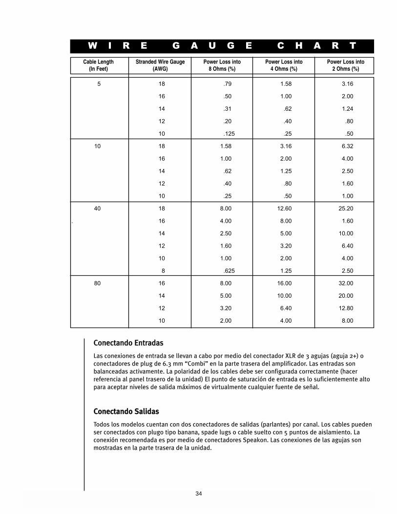
34
W I R E G A U G E C H A R T
Cable Length(In Feet)
Stranded Wire Gauge(AWG)
Power Loss into 8 Ohms (%)
Power Loss into 4 Ohms (%)
Power Loss into 2 Ohms (%)
5 18 .79 1.58 3.16
16 .50 1.00 2.00
14 .31 .62 1.24
12 .20 .40 .80
10 .125 .25 .50
10 18 1.58 3.16 6.32
16 1.00 2.00 4.00
14 .62 1.25 2.50
12 .40 .80 1.60
10 .25 .50 1.00
40 18 8.00 12.60 25.20
. 16 4.00 8.00 1.60
14 2.50 5.00 10.00
12 1.60 3.20 6.40
10 1.00 2.00 4.00
8 .625 1.25 2.50
80 16 8.00 16.00 32.00
14 5.00 10.00 20.00
12 3.20 6.40 12.80
10 2.00 4.00 8.00
CCoonneeccttaannddoo EEnnttrraaddaass
Las conexiones de entrada se llevan a cabo por medio del conectador XLR de 3 agujas (aguja 2+) o
conectadores de plug de 6.3 mm “Combi” en la parte trasera del amplificador. Las entradas son
balanceadas activamente. La polaridad de los cables debe ser configurada correctamente (hacer
referencia al panel trasero de la unidad) El punto de saturación de entrada es lo suficientemente alto
para aceptar niveles de salida máximos de virtualmente cualquier fuente de señal.
CCoonneeccttaannddoo SSaalliiddaass
Todos los modelos cuentan con dos conectadores de salidas (parlantes) por canal. Los cables pueden
ser conectados con plugo tipo banana, spade lugs o cable suelto con 5 puntos de aislamiento. La
conexión recomendada es por medio de conectadores Speakon. Las conexiones de las agujas son
mostradas en la parte trasera de la unidad.
35
CCoonneeccttaannddoo CCoorrrriieennttee
Los requisitos de corriente del amplificador CS 800H han sido medidos a 1/8 de poder (condiciones
de música típicas) y 1/3 de poder (condiciones de música extremas). La máxima necesidad de
corriente es limitada sólo por el breaker en el panel frontal. Consulta las especificaciones de este
manual para cifras de corriente que este amplificador demanda. Hay que asegurarse que el voltaje es
el correcto y es el mismo que el impreso en la parte trasera del amplificador. Cualquier daño que
resulte de la conexión del amplificador a corriente inapropiada no es cubierto por ninguna garantía. A
menos que se especifique lo contrario, los amplificadores Peavey que salen de fábrica cuentan con la
siguiente configuración:
América del Norte: 120 VAC/60 Hz
Europa, Asia, Australia: 230/240 VAC/50 Hz
América del Sur: 120 VAC/60 Hz ó 240 VAC/50 Hz
EEssttéérreeoo
Para operación estéreo (dos canales), apaga el amplificador y ajusta el interruptor de modo en la
posición estéreo (stereo). En este modo los dos canales operan independientemente de si mismos,
con los atenuadores de entrada controlando sus niveles respectivos. Por lo tanto, una señal que entra
al Canal A producirá una señal amplificada en la salida del Canal A, mientras que una señal que entra
al Canal B producirá una señal amplificada en la salida del Canal B.
PPaarraalleelloo
Para operación Paralela (dos canales/una salida), apaga el amplificador y ajusta el interruptor de
modo en la posición paralela (parallel); ambos canales del amplificador se alimentarán de la señal en
la entrada del Canal A. No se necesita ninguna conexión adicional. Las conexiones de salida son las
mismas que en el modo estéreo. En modo paralelo, sólo estará activa la entrada del Canal A; el Canal
B estará “fuera del circuito”. Ambos atenuadores de entrada permanecerán activos, permitiéndote
asignar diferentes volúmenes a cada canal. La corriente y otras especificaciones generales son las
mismas que en el modo estéreo.
MMoonnoo PPuueennttee
Ambos canales del amplificador pueden ser ‘puenteados’ para hacer un amplificador monoaural muy
poderoso. Usa precaución extrema cuando se opere en este modo; las terminales de salida pueden
producir voltajes a niveles que pueden causar la muerte. Para poner el amplificador en este modo,
hay que ajustar el interruptor de la parte trasera a posición de puente (bridge). Aplicar señal a la
entrada del Canal A (todas las funciones de entrada del Canal B son canceladas) y conectar los
parlantes a las salidas activas (las marcadas con el signo “+” en los puentes de conexión de los
Canales A y B) o entre las agujas 1+ y 2+ del conectador Speakon del Canal A. El control de nivel de
entrada del Canal A será el control maestro de nivel, el control de nivel del canal B no es operable. Le
LED de activo del canal B no se encenderá, por lo que es fácil identificar cuándo el amplificador está
en modo puente.
A diferencia del modo estéreo, en las que un lado de cada salida es tierra, en el modo mono/puente
ambos lados están activos. Si se usa un panel de parche de salida, todas las conexiones deben estar
aisladas entre ellas y del panel. La carga de impedancia nominal mínima recomendada en el modo de
puente es 4 Ohmios (equivalente a 2 Ohmios en cada canal). Usar cargas de menos de 4 Ohmios
activará los circuitos LFC y resultará en pérdida de poder y también puede causar saturación térmica.
MMooddooss ddee OOppeerraacciióónn
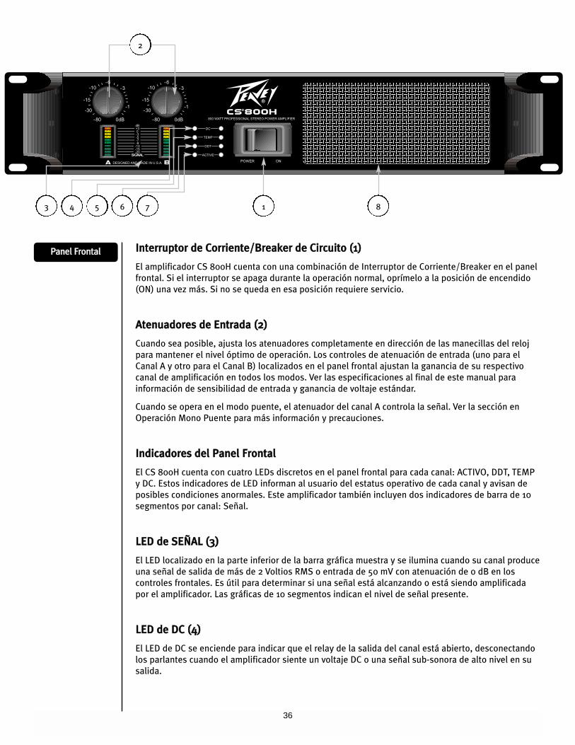
36
IInntteerrrruuppttoorr ddee CCoorrrriieennttee//BBrreeaakkeerr ddee CCiirrccuuiittoo ((11))
El amplificador CS 800H cuenta con una combinación de Interruptor de Corriente/Breaker en el panel
frontal. Si el interruptor se apaga durante la operación normal, oprímelo a la posición de encendido
(ON) una vez más. Si no se queda en esa posición requiere servicio.
AAtteennuuaaddoorreess ddee EEnnttrraaddaa ((22))
Cuando sea posible, ajusta los atenuadores completamente en dirección de las manecillas del reloj
para mantener el nivel óptimo de operación. Los controles de atenuación de entrada (uno para el
Canal A y otro para el Canal B) localizados en el panel frontal ajustan la ganancia de su respectivo
canal de amplificación en todos los modos. Ver las especificaciones al final de este manual para
información de sensibilidad de entrada y ganancia de voltaje estándar.
Cuando se opera en el modo puente, el atenuador del canal A controla la señal. Ver la sección en
Operación Mono Puente para más información y precauciones.
IInnddiiccaaddoorreess ddeell PPaanneell FFrroonnttaall
El CS 800H cuenta con cuatro LEDs discretos en el panel frontal para cada canal: ACTIVO, DDT, TEMP
y DC. Estos indicadores de LED informan al usuario del estatus operativo de cada canal y avisan de
posibles condiciones anormales. Este amplificador también incluyen dos indicadores de barra de 10
segmentos por canal: Señal.
LLEEDD ddee SSEEÑÑAALL ((33))
El LED localizado en la parte inferior de la barra gráfica muestra y se ilumina cuando su canal produce
una señal de salida de más de 2 Voltios RMS o entrada de 50 mV con atenuación de 0 dB en los
controles frontales. Es útil para determinar si una señal está alcanzando o está siendo amplificada
por el amplificador. Las gráficas de 10 segmentos indican el nivel de señal presente.
LLEEDD ddee DDCC ((44))
El LED de DC se enciende para indicar que el relay de la salida del canal está abierto, desconectando
los parlantes cuando el amplificador siente un voltaje DC o una señal sub-sonora de alto nivel en su
salida.
PPaanneell FFrroonnttaall
2
1 84 5 6 73
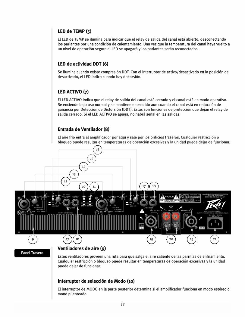
37
LLEEDD ddee TTEEMMPP ((55))
El LED de TEMP se ilumina para indicar que el relay de salida del canal está abierto, desconectando
los parlantes por una condición de calentamiento. Una vez que la temperatura del canal haya vuelto a
un nivel de operación segura el LED se apagará y los parlantes serán reconectados.
LLEEDD ddee aaccttiivviiddaadd DDDDTT ((66))
Se ilumina cuando existe compresión DDT. Con el interruptor de activo/desactivado en la posición de
desactivado, el LED indica cuando hay distorsión.
LLEEDD AACCTTIIVVOO ((77))
El LED ACTIVO indica que el relay de salida del canal está cerrado y el canal está en modo operativo.
Se enciende bajo uso normal y se mantiene encendido aun cuando el canal está en reducción de
ganancia por Detección de Distorsión (DDT). Estas son funciones de protección que dejan el relay de
salida cerrado. Si el LED ACTIVO se apaga, no habrá señal en las salidas.
EEnnttrraaddaa ddee VVeennttiillaaddoorr ((88))
El aire frío entra al amplificador por aquí y sale por los orificios traseros. Cualquier restricción o
bloqueo puede resultar en temperaturas de operación excesivas y la unidad puede dejar de funcionar.
VVeennttiillaaddoorreess ddee aaiirree ((99))
Estos ventiladores proveen una ruta para que salga el aire caliente de las parrillas de enfriamiento.
Cualquier restricción o bloqueo puede resultar en temperaturas de operación excesivas y la unidad
puede dejar de funcionar.
IInntteerrrruuppttoorr ddee sseelleecccciióónn ddee MMooddoo ((1100))
El interruptor de MODO en la parte posterior determina si el amplificador funciona en modo estéreo o
mono puenteado.
PPaanneell TTrraasseerroo
12
10 11
17 18 19 19 2120
17 18
9
13
14
15
16
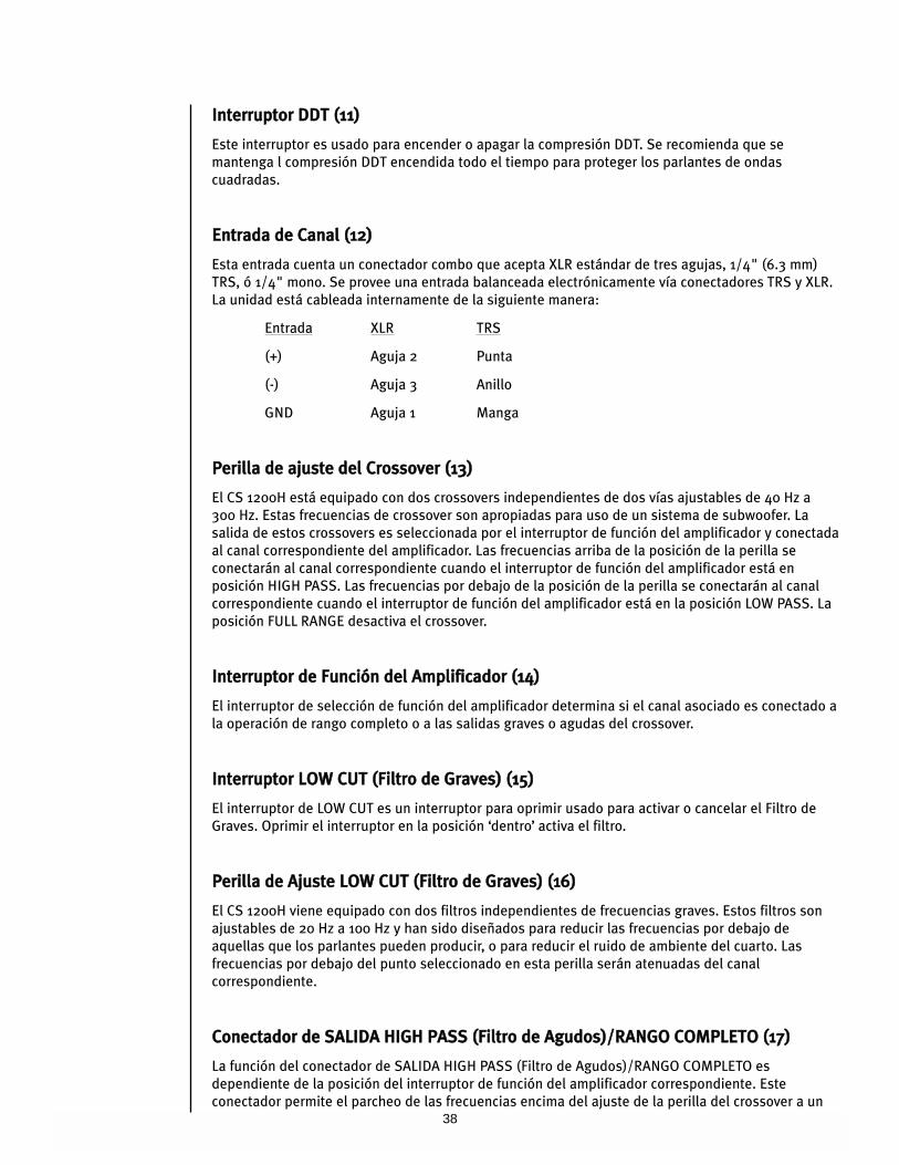
38
IInntteerrrruuppttoorr DDDDTT ((1111))
Este interruptor es usado para encender o apagar la compresión DDT. Se recomienda que se
mantenga l compresión DDT encendida todo el tiempo para proteger los parlantes de ondas
cuadradas.
EEnnttrraaddaa ddee CCaannaall ((1122))
Esta entrada cuenta un conectador combo que acepta XLR estándar de tres agujas, 1/4" (6.3 mm)
TRS, ó 1/4" mono. Se provee una entrada balanceada electrónicamente vía conectadores TRS y XLR.
La unidad está cableada internamente de la siguiente manera:
Entrada XLR TRS
(+) Aguja 2 Punta
(-) Aguja 3 Anillo
GND Aguja 1 Manga
PPeerriillllaa ddee aajjuussttee ddeell CCrroossssoovveerr ((1133))
El CS 1200H está equipado con dos crossovers independientes de dos vías ajustables de 40 Hz a
300 Hz. Estas frecuencias de crossover son apropiadas para uso de un sistema de subwoofer. La
salida de estos crossovers es seleccionada por el interruptor de función del amplificador y conectada
al canal correspondiente del amplificador. Las frecuencias arriba de la posición de la perilla se
conectarán al canal correspondiente cuando el interruptor de función del amplificador está en
posición HIGH PASS. Las frecuencias por debajo de la posición de la perilla se conectarán al canal
correspondiente cuando el interruptor de función del amplificador está en la posición LOW PASS. La
posición FULL RANGE desactiva el crossover.
IInntteerrrruuppttoorr ddee FFuunncciióónn ddeell AAmmpplliiffiiccaaddoorr ((1144))
El interruptor de selección de función del amplificador determina si el canal asociado es conectado a
la operación de rango completo o a las salidas graves o agudas del crossover.
IInntteerrrruuppttoorr LLOOWW CCUUTT ((FFiillttrroo ddee GGrraavveess)) ((1155))
El interruptor de LOW CUT es un interruptor para oprimir usado para activar o cancelar el Filtro de
Graves. Oprimir el interruptor en la posición ‘dentro’ activa el filtro.
PPeerriillllaa ddee AAjjuussttee LLOOWW CCUUTT ((FFiillttrroo ddee GGrraavveess)) ((1166))
El CS 1200H viene equipado con dos filtros independientes de frecuencias graves. Estos filtros son
ajustables de 20 Hz a 100 Hz y han sido diseñados para reducir las frecuencias por debajo de
aquellas que los parlantes pueden producir, o para reducir el ruido de ambiente del cuarto. Las
frecuencias por debajo del punto seleccionado en esta perilla serán atenuadas del canal
correspondiente.
CCoonneeccttaaddoorr ddee SSAALLIIDDAA HHIIGGHH PPAASSSS ((FFiillttrroo ddee AAgguuddooss))//RRAANNGGOO CCOOMMPPLLEETTOO ((1177))
La función del conectador de SALIDA HIGH PASS (Filtro de Agudos)/RANGO COMPLETO es
dependiente de la posición del interruptor de función del amplificador correspondiente. Este
conectador permite el parcheo de las frecuencias encima del ajuste de la perilla del crossover a un
39
amplificador secundario. Si el interruptor de función del amplificador está en posición HIGH PASS, la
porción de frecuencias agudas del crossover estará presente en el conectador. Si el interruptor de
función del amplificador está en la posición FULL RANGE (rango completo) o LOW PASS, el crossover
no estará activo y se permitirá la conexión de la señal de rango completo a un amplificador
secundario.
SSAALLIIDDAA ddee LLOOWW PPAASSSS ((1188))
El conectador de la SALIDA de LOW PASS permite el parcheo de las frecuencias por debajo de la
posición de la perilla del crossover a un amplificador secundario. Esta salida permanece
independiente de las frecuencias graves de la posición del interruptor de función del amplificador.
CCoonneeccttaaddoorr ddee ssaalliiddaa SSppeeaakkoonn ((1199))
Cada canal cuenta con un conectador de cuatro cables Speakon para su salida. En ambos canales, la
aguja 1+ es la señal de salida y la aguja 1- es la tierra del chasis. En el conectador del Canal A la aguja
2+ lleva la señal de salida del Canal B y la aguja 2- es la tierra del chasis.
CCoonneeccttoorreess ddee ssaalliiddaa ddee ppoossttee ((bbiinnddiinngg ppoosstt)) ((2200))
Cada canal cuenta con un par de conectadores de poste conectados en paralelo al conectador
Speakon. Los postes rojos son la señal de salida de cada canal, y los postes negros son la tierra del
chasis. Para operación n modo puenteado, sólo se usan los postes rojos. El poste rojo del Canal A
debe ser considerado salida positiva del sistema y debe ser conectado a la entrada positiva del
sistema de parlantes asociado.
CCoonneeccttaaddoorr ee ccoorrrriieennttee CCAA ((2211))
Este acepta el cable de corriente IEC incluido. Debe ser conectado únicamente a una fuente de
corriente apropiada (ver instrucciones en la parte posterior de la unidad).
El CS 800H incorpora varios circuitos para protegerse tanto a ellos mismos como a los parlantes en
virtualmente cualquier situación. Peavey ha intentado hacer estas unidades contra todo, haciéndolas
inmunes a cortos circuitos y circuitos abiertos, cargas diferentes, voltaje DC o sobrecalentamiento. Si
un canal entra en Detección de Distorsión o modo de reducción de ganancia DDT, la carga del
parlante permanece conectada, pero el porcentaje de saturación y poder de salida son reducidos
instantáneamente. Cuando ocurre un problema que causa que el canal entre en modo de protección,
el LED de TEMP o LED de DC para ese canal se encenderán. Corriente DC en la salida, frecuencias sub-
sonoras excesivas, o saturación térmica causarán que el relay de salida desconecte la carga del
parlante hasta que el problema haya sido corregido o el amplificador se enfríe.
DDDDTT
El sistema de compresión DDT de Peavey permite la mejor ejecución de la combinación del
amplificador y los parlantes previniendo que el amplificador funcione por encima de su umbral
(saturación). El sistema de compresión es activado por un circuito único que es sensible a las
condiciones de la señal que pueden saturar al amplificador y reducir su ganancia cuando comienza la
saturación. El umbral de compresión es la saturación en si y no se usa un control específico de
umbral. Esta técnica utiliza eficientemente cada watt disponible al amplificador para reproducir la
señal mientras al mismo tiempo minimiza la distorsión, reduciendo de forma significante el potencial
de degradación y a los parlantes.
FFuunncciioonneess ddee PPrrootteecccciióónn
40
LLiimmiittaacciióónn ddee DDeetteecccciióónn ddee DDiissttoorrssiióónn
En cualquier momento que un canal produzca mucha energía, o saturación continua, el circuito DDT
automáticamente reduce la ganancia del canal a un nivel justo por debajo de la saturación,
protegiendo a los parlantes contra ondas cuadradas continuas que se pueden producir. Las
situaciones que pueden activar el circuito DDT incluyen retroalimentación descontrolada,
oscilaciones, o una instalación incorrecta o una falla en la corriente del amplificador. En el CS 800H,
los transientes del programa normal no dispararán el DDT; sólo la saturación continua excesiva. El
LED de DDT se encenderá continuamente cuando se experimente saturación.
SSeennssiibbiilliiddaadd ddee IImmppeeddaanncciiaa LLFFCC
El amplificador CS 800H cuenta con circuitos innovadores que permiten su operación segura a
cualquier carga. Cuando el amplificador identifica una carga que lo sobrecargará en la salida, el
circuito de Corrección de Carga Fallida (LFC por sus siglas en inglés) ajusta la ganancia del canal a un
nivel seguro. Este método de protección en la salida es muy superior a la limitación convencional que
se encuentra en otros amplificadores. El circuito LFC es transparente al oído en uso normal y discreto
cuando es activado.
PPrrootteecccciióónn TTéérrmmiiccaa
Los ventiladores internos mantendrán al amplificador operando dentro de su rango de temperatura
bajo condiciones normales. Si la temperatura de la parrilla de calor de un canal alcanza los 85°C, que
puede ser indicación de una obstrucción en las entradas de aire, ese canal se protegerá
independientemente desconectando su carga y apagándose hasta que se enfríe. Durante este tiempo
el LED de TEMP del canal se encenderá. Durante este tiempo el LED ACTIVO se apagará, el LED de
TEMP y DDT se mantendrán encendido y los ventiladores se mantendrán activos a velocidad alta.
CCoorrttooss CCiirrccuuiittooss
Si una salida tiene un corto, el LFC y circuitos de protección de temperatura automáticamente
protegerán el amplificador. El circuito LFC identifica el corto como una condición de carga extrema y
atenúa la señal, protegiendo los transistores de salida del canal de sobrecargarse. Si el corto
continua, el canal eventualmente se protegerá a si mismo térmicamente desconectando la carga.
CCoorrttooss CCiirrccuuiittooss
Si una salida tiene un corto, el LFC automáticamente protegerá al amplificador. El circuito LFC
identifica el corto como una condición de carga extrema y atenúa la señal, protegiendo los
transistores de salida del canal de sobrecargarse. Aproximadamente 1.5 segundos más tarde el
circuito RampUp tratará de regresar al amplificador a su operación normal. Si el corto continua, el
circuito LFC muteará la señal. Este ciclo de operación puede continuar hasta que el corto ya no esté
presente en la salida.
PPrrootteecccciióónn ddee vvoollttaajjee DDCC
Si un canal del amplificador detecta voltaje DC o frecuencias sub-sonoras en sus terminales de salida,
su relay de salida inmediatamente se abrirá para prevenir daños en los parlantes. El LED DC del canal
se encenderá.
41
PPrrootteecccciióónn ddee EEnncceennddiiddoo//AAppaaggaaddoo
Durante el encendido el amplificador se mantiene en modo de protección, con las salidas desconectadas, por
aproximadamente cuatro segundos mientras que la fuente de poder se carga y estabiliza. Mientras los relays de salida están
abiertos, el LED de DDT se encenderá. Cuando se quita la corriente, las cargas de los parlantes se desconectan
inmediatamente para evitar los ‘pops’ y ‘tumps’.
CCoonnttrrooll ddee sseeññaall RRaammppUUpp™™
Siempre que el amplificador es encendido o sale de modo de protección, el circuito RampUp™ se activa. Cuando los parlantes
están desconectados, el circuito RampUp™ atenúa la señal por completo. Una vez que el relay de salida se cierra, la señal
sube su nivel lenta y gradualmente. El circuito de control de señal RampUp™ tiene ventajas importantes sobre los circuitos
convencionales de encendido instantáneo:
Si una señal está presente durante el encendido (o saliendo de un modo de protección), los parlantes no experimentarán
un sonido fuerte repentino.
Dado que la ganancia es reducida hasta que el relay de salida se cierra, no ocurre estrés en los contactos, extendiendo la
vida de la unidad.
PPrrootteecccciióónn ddee PPaarrllaanntteess
Todos los parlantes cuentan con límites eléctricos, térmicos y físicos que deben ser tomados en cuenta para prevenir daños o
fallas. Demasiado poder, frecuencias graves aplicadas a drivers de frecuencias agudas, ondas severamente saturadas, y voltaje
DC pueden ser fatales al cono y drivers de compresión. El amplificador CS 800H de Peavey protege los parlantes de voltajes DC
y señales sub-sonoras de manera automática. Para más información, ver la sección en Funciones de Protección. Los parlantes
de frecuencias medias-agudas, especialmente los drivers de compresión, son altamente susceptibles a daños por demasiado
poder, ondas saturadas o frecuencias por debajo su capacidad. Hay que tener mucho cuidado que las bandas graves y media
del crossover electrónico sean conectadas a los amplificadores y drivers correctos y que no sean conectados accidentalmente a
aquellos para una frecuencia más grave. El punto de saturación del amplificador es su pico máximo de poder de salida, el
amplificador CS 800H de alta capacidad de Peavey puede generar mucho más poder del que muchos parlantes pueden recibir.
Asegúrate que el pico de poder del amplificador no es excesivo para tus parlantes.
También puedes usar fusibles para limitar el poder a los drivers de los parlantes, aunque como limitadores de corriente y no
limitadores de voltaje, son una solución imperfecta, y como los eslabones más débiles, sólo limitan una vez antes de necesitar
ser reemplazados. Algunos fusibles de baja calidad cuentan con resistencia considerable que puede degradar la capacidad del
amplificador de controlar el movimiento del parlante y pueden hasta llegar a deteriorar la calida de sonido del sistema. Si
quieres usar fusibles, verifica con el fabricante del parlante para determinar las especificaciones de corriente y tiempo
requeridas.
No se alimente ningún parlante de frecuencias graves con frecuencias por debajo de la frecuencias a la que ha sido afinado,
esto puede causar daños al parlante, aun a niveles relativamente bajos de operación. Consulta las especificaciones de sistema
de parlantes para determinar los límites de frecuencias.
MMaanntteenniimmiieennttoo ddeell AAmmpplliiffiiccaaddoorr yy RReessppoonnssaabbiilliiddaadd ddeell UUssuuaarriioo
El amplificador CS 800H no requieren mantenimiento regular y no deben requerir ningún ajuste interno durante su vida. Tu
amplificador CS 800H es muy poderoso y puede ser potencialmente peligroso a parlantes y humanos por igual. Es tu
responsabilidad leer la Sección de Precauciones Importantes y asegurarte que el amplificador es instalado, cableado y
operado propiamente y de acuerdo con este manual. Muchos parlantes pueden sufrir daños fácilmente o ser destruidos por
niveles elevados de poder, especialmente con la cantidad de poder que produce un amplificador puenteado. Lee la Sección de
Protección de Parlantes y siempre toma en cuenta la capacidad pico y continua del parlante.
42
Glosario de Términos((UUssaaddoo eenn IInnssttrruucccciioonneess ddee IInnssttaallaacciióónn))
Estéreo: Música con dos canales separados, usualmente derecho e izquierdo.
Mono: Música con sólo un canal
Crossover: Un aparato electrónico que separa las frecuencias graves y agudas y las envía a diferentes salidas.
Las señales separadas generalmente son enviadas a una salida grave y una aguda.
Bi-amp: La separación de frecuencias graves y agudas sin crossover, usando parlantes diferentes y
amplificadores para cada una.
Rango Completo: Frecuencias graves y agudas juntas en un solo canal.
Programa: La señal que se conecta al amplificador.
Hi-Pass: Permite sólo el paso de frecuencias agudas, bloqueando las frecuencias graves.
Low Pass: Permite sólo el paso de frecuencias graves, bloqueando las frecuencias agudas.
Mid/High: El parlante diseñado para reproducir todas las frecuencias menos las graves.
Sub: El parlante diseñado sólo para frecuencias graves.
Paralelo: Ambos parlantes o entradas con la misma señal. Cuando se habla de parlantes, esto significa
conectar el segundo parlante a la primera.
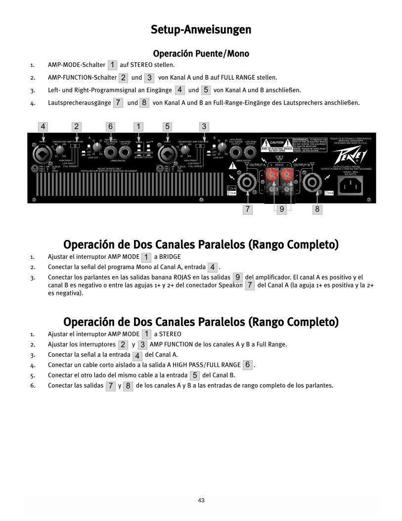
43
SSeettuupp--AAnnwweeiissuunnggeenn
OOppeerraacciióónn PPuueennttee//MMoonnoo1. AMP-MODE-Schalter auf STEREO stellen.
2. AMP-FUNCTION-Schalter und von Kanal A und B auf FULL RANGE stellen.
3. Left- und Right-Programmsignal an Eingänge und von Kanal A und B anschließen.
4. Lautsprecherausgänge und von Kanal A und B an Full-Range-Eingänge des Lautsprechers anschließen.
OOppeerraacciióónn ddee DDooss CCaannaalleess PPaarraalleellooss ((RRaannggoo CCoommpplleettoo))1. Ajustar el interruptor AMP MODE a BRIDGE
2. Conectar la señal del programa Mono al Canal A, entrada .
3. Conectar los parlantes en las salidas banana ROJAS en las salidas del amplificador. El canal A es positivo y el
canal B es negativo o entre las agujas 1+ y 2+ del conectador Speakon del Canal A (la aguja 1+ es positiva y la 2+
es negativa).
OOppeerraacciióónn ddee DDooss CCaannaalleess PPaarraalleellooss ((RRaannggoo CCoommpplleettoo))1. Ajustar el interruptor AMP MODE a STEREO
2. Ajustar los interruptores y AMP FUNCTION de los canales A y B a Full Range.
3. Conectar la señal a la entrada del Canal A.
4. Conectar un cable corto aislado a la salida A HIGH PASS/FULL RANGE .
5. Conectar el otro lado del mismo cable a la entrada del Canal B.
6. Conectar las salidas y de los canales A y B a las entradas de rango completo de los parlantes.
1
2 3
4 5
7
14
97
12 3
46
7 85
8
4 2 6
87 9
1 5 3
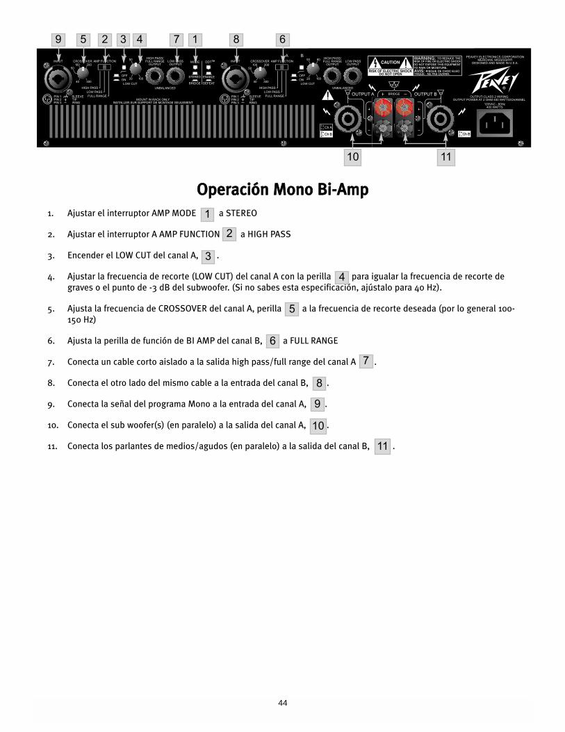
44
OOppeerraacciióónn MMoonnoo BBii--AAmmpp
1. Ajustar el interruptor AMP MODE a STEREO
2. Ajustar el interruptor A AMP FUNCTION a HIGH PASS
3. Encender el LOW CUT del canal A, .
4. Ajustar la frecuencia de recorte (LOW CUT) del canal A con la perilla para igualar la frecuencia de recorte de
graves o el punto de -3 dB del subwoofer. (Si no sabes esta especificación, ajústalo para 40 Hz).
5. Ajusta la frecuencia de CROSSOVER del canal A, perilla a la frecuencia de recorte deseada (por lo general 100-
150 Hz)
6. Ajusta la perilla de función de BI AMP del canal B, a FULL RANGE
7. Conecta un cable corto aislado a la salida high pass/full range del canal A .
8. Conecta el otro lado del mismo cable a la entrada del canal B, .
9. Conecta la señal del programa Mono a la entrada del canal A, .
10. Conecta el sub woofer(s) (en paralelo) a la salida del canal A, .
11. Conecta los parlantes de medios/agudos (en paralelo) a la salida del canal B, .
1
2
3
4
5
6
7
8
9
10
11
9 5 3 4 7 1 8 6
10 11
2
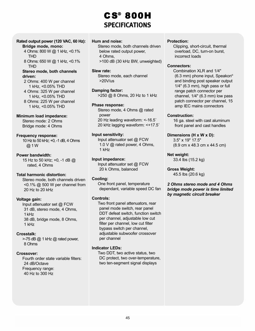
45
Rated output power (120 VAC, 60 Hz):Bridge mode, mono:4 Ohms: 800 W @ 1 kHz, <0.1%
THD8 Ohms: 650 W @ 1 kHz, <0.1%
THDStereo mode, both channelsdriven:2 Ohms: 400 W per channel
1 kHz, <0.05% THD4 Ohms: 325 W per channel
1 kHz, <0.05% THD8 Ohms: 225 W per channel
1 kHz, <0.05% THD
Minimum load impedance:Stereo mode: 2 OhmsBridge mode: 4 Ohms
Frequency response:10 Hz to 50 kHz; +0‚ -1 dB, 4 Ohms
@ 1 W
Power bandwidth:15 Hz to 50 kHz; +0‚ -1 dB @
rated, 4 Ohms
Total harmonic distortion:Stereo mode, both channels driven<0.1% @ 500 W per channel from 20 Hz to 20 kHz
Voltage gain:Input attenuator set @ FCW 31 dB, stereo mode, 4 Ohms,1 kHz 38 dB, bridge mode, 8 Ohms, 1 kHz
Crosstalk:>-75 dB @ 1 kHz @ rated power, 8 Ohms
Crossover:Fourth order state variable filters: 24 dB/Octave
Frequency range:40 Hz to 300 Hz
Hum and noise:Stereo mode, both channels drivenbelow rated output power, 4 Ohms, >100 dB (30 kHz BW, unweighted)
Slew rate:Stereo mode, each channel>20V/us
Damping factor:>250 @ 8 Ohms, 20 Hz to 1 kHz
Phase response:Stereo mode, 4 Ohms @ rated power
20 Hz leading waveform: <-16.5˚20 kHz lagging waveform: <+17.5˚
Input sensitivity:Input attenuator set @ FCW1.0 V @ rated power, 4 Ohms, 1 kHz
Input impedance:Input attenuator set @ FCW20 k Ohms, balanced
Cooling:One front panel, temperature dependant, variable speed DC fan
Controls:Two front panel attenuators‚ rear panel mode switch‚ rear panelDDT defeat switch, function switchper channel, adjustable low cutfilter per channel, low cut filterbypass switch per channel,adjustable subwoofer crossoverper channel
Indicator LEDs:Two DDT, two active status, two DC protect, two over-temperature,two ten-segment signal displays
Protection:Clipping, short-circuit, thermal overload, DC, turn-on burst,incorrect loads
Connectors:Combination XLR and 1/4" (6.3 mm) phone input, Speakon®
and binding post speaker output1/4" (6.3 mm), high pass or fullrange patch connector perchannel, 1/4" (6.3 mm) low passpatch connector per channel, 15amp IEC mains connectors
Construction:16 ga. steel with cast aluminum front panel and cast handles
Dimensions (H x W x D):3.5" x 19" 17.5"(8.9 cm x 48.3 cm x 44.5 cm)
Net weight:33.4 lbs (15.2 kg)
Gross Weight:45.5 lbs (20.6 kg)
2 Ohms stereo mode and 4 Ohmsbridge mode power is time limitedby magnetic circuit breaker
CS®® 800HSSPPEECCIIFFIICCAATTIIOONNSS
46
FFRRAANNÇÇAAIISS
CCaarraaccttéérriissttiiqquueess
DDeessccrriippttiioonnAAmmpplliiffiiccaatteeuurrss ddee PPuuiissssaannccee CCSS 880000HH
Félicitations d’avoir choisi un amplificateur de puissance Peavey CS 800H. Ces unités sont concues
pour vous permettre une utilisation intensive sans problèmes de fiabilité ou d’utilisation. Le tout dans
une unité compacte, ils proposent une circuiterie de pointe et des systèmes de protection qui ont fait
la renommée de Peavey. L’un d’entre eux, le DDDDTT™™ (Distortion Detection), est un circuit qui permet
d’optimiser les performances de l’amplificateur sous grande charge en analysant le signal et le
maintenant dans la zone de travail de votre amplificateur. Le système de ventilation breveté des
amplificateurs CS, une combinaison de ventilateur à vitesse variable et de radiateurs ‘à tunnels’ vous
permettent de garder une efficacité maximum même après plusieurs heures d’utilisation.
Bien que ces unités soient d’une très grande facilité d’utilisation et sont protégés par un chassis
d’acier robuste, il vous faut quand même respecter des règles simples pour en tirer le meilleur parti.
Certains d’entre eux peuvent générer de grandes puissances et donc travaille sur des signaux à haut
voltage.
PPOOUURR VVOOTTRREE PPRROOPPRREE SSEECCUURRIITTEE EETT CCEELLLLEE DDEE VVOOTTRREE MMAATTEERRIIEELL,, LLIISSEEZZ AATTTTEENNTTIIVVEEMMEENNTT CCEE MMAANNUUEELL..
·· UUnniittéé aauu ssttaannddaarrdd RRaacckk 1199"" ((22--UU))
·· SSyyssttèèmmee ddee rreeffrrooiiddiisssseemmeenntt ‘‘ttuunnnneell--ccoooolleedd’’ eett vveennttiillaatteeuurr àà vviitteessssee vvaarriiaabbllee..
·· CChhaassssiiss ttrrèèss rrééssiissttaanntt
·· CCoonnttrrôôllee ddee llaa mmoonnttééee eenn ppuuiissssaannccee aauu ddéémmaarrrraaggee RRaammppUUpp™™
·· 33 mmooddee ddee ffoonnccttiioonnnneemmeenntt :: SSttéérrééoo‚‚ PPaarraallllèèllee oouu PPoonntt ((bbrriiddggee))
·· IInntteerrrruupptteeuurr eett ddiissjjoonncctteeuurr ssuurr llee ppaannnneeaauu aavvaanntt
·· IInntteerrrruupptteeuurr ddee ffoonnccttiioonnnneemmeenntt PPlleeiinn RReeggiissttrree//PPaarrtt dduu RRggiissttrree ((BBaasssseess oouu HHaauutteess ffrrééqquueenncceess))
·· DDeeuuxx ffiillttrreess aaccttiiffss iinnddééppeennddaannttss eett ccoonnttrrôôllaabblleess
·· DDeeuuxx ffiillttrreess ccoouuppee--bbaass iinnddééppeennddaannttss
·· 55 LLeeddss dd’’iinnddiiccaattiioonn ssuurr llaa ppaannnneeaauu aavvaanntt :: AACCTTIIVVEE,, DDDDTT™™,, SSIIGGNNAALL‚‚ TTEEMMPP eett DDCC
DDéébbaallllaaggee
Inspecter votre unité lors du déballage. Au moindre problème, notifiez-le à votre revendeur
immédiatement. Assurez-vous de garder les emballages de votre unité, ils vous seront nécessaires si
jamais vous devez envoyer votre unité à un centre technique ou distributeur. Si vous devez nous
retourner votre unité et que vous ne possédiez plus le carton d’emballage, contactez-nous pour vous
en fournir un.
IInnssttaallllaattiioonn
Le CS 800H Series est concu pour de nombreuses applications, aussi bien en installation (système à
demeure, home studio,...) qu’en système mobile. Il est au format rack 19" standard 2U de 16"
(406 mm) de profondeur et est équipé d’oreilles de fixations supplémentaires sur l’arrière.
RReeffrrooiiddiisssseemmeenntt
Les amplificateurs de la série CS utilisent un système de refroidissement à air forcé pour maintenir
une parfaite température de fonctionnement. L’air est aspiré par les ventilateurs du panneau avant,
passent le long des radiateurs en formes de tunels (pour le meilleur échange thermique possible) et
sont expulsés par le panneau arrière. Si le radiateur atteint des températures élevées, une protection
disconnectera la charge du côté concerné. Il est primordial d’avoir un excellent système de
refroidissement. Si vous utilisez vos unités en Rack, ne jamais les faire fonctionner avec le couvercle
avant fermé. De même, si vous l’arrière du rack est fermé, prévoyez au moins un espace libre tous les
3 amplificateurs de puissance.
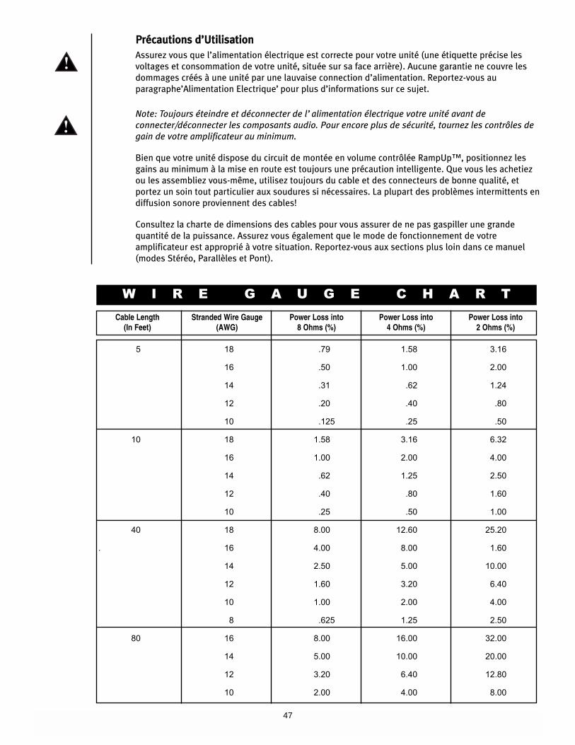
47
PPrrééccaauuttiioonnss dd’’UUttiilliissaattiioonn
Assurez vous que l’alimentation électrique est correcte pour votre unité (une étiquette précise les
voltages et consommation de votre unité, située sur sa face arrière). Aucune garantie ne couvre les
dommages créés à une unité par une lauvaise connection d’alimentation. Reportez-vous au
paragraphe’Alimentation Electrique’ pour plus d’informations sur ce sujet.
Note: Toujours éteindre et déconnecter de l’alimentation électrique votre unité avant de
connecter/déconnecter les composants audio. Pour encore plus de sécurité, tournez les contrôles de
gain de votre amplificateur au minimum.
Bien que votre unité dispose du circuit de montée en volume contrôlée RampUp™, positionnez les
gains au minimum à la mise en route est toujours une précaution intelligente. Que vous les achetiez
ou les assembliez vous-même, utilisez toujours du cable et des connecteurs de bonne qualité, et
portez un soin tout particulier aux soudures si nécessaires. La plupart des problèmes intermittents en
diffusion sonore proviennent des cables!
Consultez la charte de dimensions des cables pour vous assurer de ne pas gaspiller une grande
quantité de la puissance. Assurez vous également que le mode de fonctionnement de votre
amplificateur est approprié à votre situation. Reportez-vous aux sections plus loin dans ce manuel
(modes Stéréo, Parallèles et Pont).
W I R E G A U G E C H A R T
Cable Length(In Feet)
Stranded Wire Gauge(AWG)
Power Loss into 8 Ohms (%)
Power Loss into 4 Ohms (%)
Power Loss into 2 Ohms (%)
5 18 .79 1.58 3.16
16 .50 1.00 2.00
14 .31 .62 1.24
12 .20 .40 .80
10 .125 .25 .50
10 18 1.58 3.16 6.32
16 1.00 2.00 4.00
14 .62 1.25 2.50
12 .40 .80 1.60
10 .25 .50 1.00
40 18 8.00 12.60 25.20
. 16 4.00 8.00 1.60
14 2.50 5.00 10.00
12 1.60 3.20 6.40
10 1.00 2.00 4.00
8 .625 1.25 2.50
80 16 8.00 16.00 32.00
14 5.00 10.00 20.00
12 3.20 6.40 12.80
10 2.00 4.00 8.00
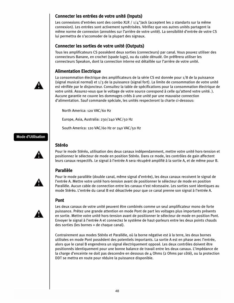
48
CCoonnnneecctteerr lleess eennttrrééeess ddee vvoottrree uunniittéé ((IInnppuuttss))
Les connexions d’entrées sont des combo XLR / 1/4"Jack (acceptent les 2 standarts sur la même
connexion). Les entrées sont activement symétrisées. Vérifiez que vos autres unités partagent la
même norme de connexion (annotées sur l’arrière de votre unité). La sensibilité d’entrée de votre CS
lui permettra de s’accomoder de la plupart des signaux.
CCoonnnneecctteerr lleess ssoorrttiieess ddee vvoottrree uunniittéé ((OOuuttppuuttss))
Tous les amplificateurs CS possèdent deux sorties (connecteurs) par canal. Vous pouvez utiliser des
connecteurs Banane, en crochet (spade lugs), ou du cable dénudé. On préfèrera utiliser les
connecteurs Speakon, dont la connection interne est détaillée sur l’arrière de votre unité.
AAlliimmeennttaattiioonn EElleeccttrriiqquuee
La consommation électrique des amplificateurs de la série CS est donnée pour 1/8 de la puissance
(signal musical normal) et 1/3 de la puissance (signal fort). La limite de consommation de votre unité
est vérifiée par le disjoncteur. Consultez la table de spécifications pour la consommation électrique de
votre unité. Assurez-vous que le voltage de votre source corespond à celle qu’attend votre unité. ).
Aucune garantie ne couvre les dommages créés à une unité par une mauvaise connection
d’alimentation. Sauf commande spéciale, les unités respecteront la charte ci-dessous:
North America: 120 VAC/60 Hz
Europe, Asia, Australia: 230/240 VAC/50 Hz
South America: 120 VAC/60 Hz or 240 VAC/50 Hz
SSttéérrééoo
Pour le mode Stéréo, utilisation des deux canaux indépendamment, mettre votre unité hors-tension et
positionnez le sélecteur de mode en position Stéréo. Dans ce mode, les contrôles de gain affectent
leurs canaux respectifs. Le signal à l’entrée A sera récupéré amplifié à la sortie A, et de même pour B.
PPaarraallllèèllee
Pour le mode parallèle (double canal, même signal d’entrée), les deux canaux recoivent le signal de
l’entrée A. Mettre votre unité hors-tension avant de positionner le sélecteur de mode en position
Parallèle. Aucun cable de connection entre les canaux n’est nécessaire. Les sorties sont identiques au
mode Stéréo. L’entrée du canal B est désactivée pour que ce canal prenne son signal à l’entrée A.
PPoonntt
Les deux canaux de votre unité peuvent être combinés comme un seul amplificateur mono de forte
puissance. Prétez une grande attention en mode Pont de part les voltages plus importants présents
en sortie. Mettre votre unité hors-tension avant de positionner le sélecteur de mode en position Pont.
Envoyer le signal à l’entrée A et connectez le système de haut-parleurs entre les deux points chauds
des sorties (les bornes + de chaque canal).
Contrairement aux modes Stéréo et Parallèle, où la borne négative est à la terre, les deux bornes
utilisées en mode Pont possèdent des potentiels importants. La sortie A est en phase avec l’entrée,
alors que le canal B engendrera un signal électriquement opposé. Les deux contrôles doivent être
positionnés identiquement pour une bonne balance de travail entre les deux canaux. L’impédance de
la charge d’enceinte ne doit pas descendre en dessous de 4 Ohms (2 Ohms par côté), ou la protection
DDT se mettra en route pour réduire la puissance disponible.
MMooddee dd’’UUttiilliissaattiioonn
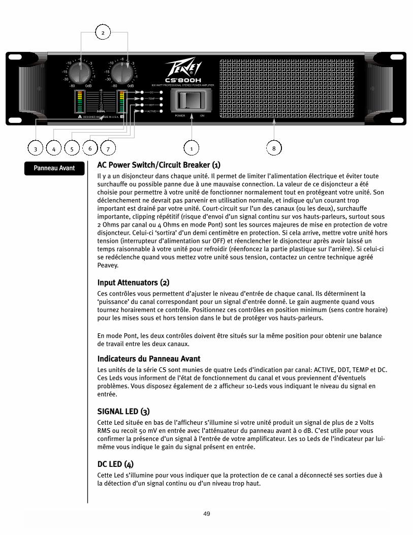
49
AACC PPoowweerr SSwwiittcchh//CCiirrccuuiitt BBrreeaakkeerr ((11))
Il y a un disjoncteur dans chaque unité. Il permet de limiter l’alimentation électrique et éviter toute
surchauffe ou possible panne due à une mauvaise connection. La valeur de ce disjoncteur a été
choisie pour permettre à votre unité de fonctionner normalement tout en protégeant votre unité. Son
déclenchement ne devrait pas parvenir en utilisation normale, et indique qu’un courant trop
important est drainé par votre unité. Court-circuit sur l’un des canaux (ou les deux), surchauffe
importante, clipping répétitif (risque d’envoi d’un signal continu sur vos hauts-parleurs, surtout sous
2 Ohms par canal ou 4 Ohms en mode Pont) sont les sources majeures de mise en protection de votre
disjoncteur. Celui-ci ‘sortira’ d’un demi centimètre en protection. Si cela arrive, mettre votre unité hors
tension (interrupteur d’alimentation sur OFF) et réenclencher le disjoncteur après avoir laissé un
temps raisonnable à votre unité pour refroidir (réenfoncez la partie plastique sur l’arrière). Si celui-ci
se redéclenche quand vous mettez votre unité sous tension, contactez un centre technique agréé
Peavey.
IInnppuutt AAtttteennuuaattoorrss ((22))
Ces contrôles vous permettent d’ajuster le niveau d’entrée de chaque canal. Ils déterminent la
‘puissance’ du canal correspondant pour un signal d’entrée donné. Le gain augmente quand vous
tournez horairement ce contrôle. Positionnez ces contrôles en position minimum (sens contre horaire)
pour les mises sous et hors tension dans le but de protéger vos hauts-parleurs.
En mode Pont, les deux contrôles doivent être situés sur la même position pour obtenir une balance
de travail entre les deux canaux.
IInnddiiccaatteeuurrss dduu PPaannnneeaauu AAvvaanntt
Les unités de la série CS sont munies de quatre Leds d’indication par canal: ACTIVE, DDT, TEMP et DC.
Ces Leds vous informent de l’état de fonctionnement du canal et vous previennent d’éventuels
problèmes. Vous disposez également de 2 afficheur 10-Leds vous indiquant le niveau du signal en
entrée.
SSIIGGNNAALL LLEEDD ((33))
Cette Led située en bas de l’afficheur s’illumine si votre unité produit un signal de plus de 2 Volts
RMS ou recoit 50 mV en entrée avec l’atténuateur du panneau avant à 0 dB. C’est utile pour vous
confirmer la présence d’un signal à l’entrée de votre amplificateur. Les 10 Leds de l’indicateur par lui-
même vous indique le gain du signal présent en entrée.
DDCC LLEEDD ((44))
Cette Led s’illumine pour vous indiquer que la protection de ce canal a déconnecté ses sorties due à
la détection d’un signal continu ou d’un niveau trop haut.
PPaannnneeaauu AAvvaanntt
2
1 84 5 6 73
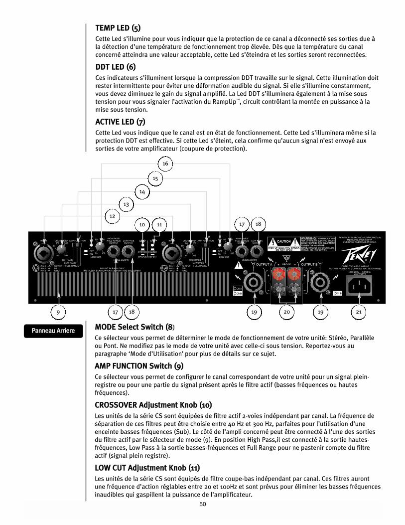
50
TTEEMMPP LLEEDD ((55))
Cette Led s’illumine pour vous indiquer que la protection de ce canal a déconnecté ses sorties due à
la détection d’une température de fonctionnement trop élevée. Dès que la température du canal
concerné atteindra une valeur acceptable, cette Led s’éteindra et les sorties seront reconnectées.
DDDDTT LLEEDD ((66))
Ces indicateurs s’illuminent lorsque la compression DDT travaille sur le signal. Cette illumination doit
rester intermittente pour éviter une déformation audible du signal. Si elle s’illumine constamment,
vous devez diminuez le gain du signal amplifié. La Led DDT s’illuminera également à la mise sous
tension pour vous signaler l’activation du RampUp™, circuit contrôlant la montée en puissance à la
mise sous tension.
AACCTTIIVVEE LLEEDD ((77))
Cette Led vous indique que le canal est en état de fonctionnement. Cette Led s’illuminera même si la
protection DDT est effective. Si cette Led s’éteint, cela confirme qu’aucun signal n’est envoyé aux
sorties de votre amplificateur (coupure de protection).
PPaannnneeaauu AArrrriieerreeMMOODDEE SSeelleecctt SSwwiittcchh ((88)
Ce sélecteur vous permet de déterminer le mode de fonctionnement de votre unité: Stéréo, Parallèle
ou Pont. Ne modifiez pas le mode de votre unité avec celle-ci sous tension. Reportez-vous au
paragraphe ‘Mode d’Utilisation’ pour plus de détails sur ce sujet.
AAMMPP FFUUNNCCTTIIOONN SSwwiittcchh ((99))
Ce sélecteur vous permet de configurer le canal correspondant de votre unité pour un signal plein-
registre ou pour une partie du signal présent après le filtre actif (basses fréquences ou hautes
fréquences).
CCRROOSSSSOOVVEERR AAddjjuussttmmeenntt KKnnoobb ((1100))
Les unités de la série CS sont équipées de filtre actif 2-voies indépendant par canal. La fréquence de
séparation de ces filtres peut être choisie entre 40 Hz et 300 Hz, parfaites pour l’utilisation d’une
enceinte basses fréquences (Sub). Le côté de l’ampli concerné peut être connecté à l’une des sorties
du filtre actif par le sélecteur de mode (9). En position High Pass,il est connecté à la sortie hautes-
fréquences, Low Pass à la sortie basses-fréquences et Full Range pour ne pastenir compte du filtre
actif (signal plein registre).
LLOOWW CCUUTT AAddjjuussttmmeenntt KKnnoobb ((1111))
Les unités de la série CS sont équipés de filtre coupe-bas indépendant par canal. Ces filtres auront
une fréquence d’action réglables entre 20 et 100Hz et sont prévus pour éliminer les basses fréquences
inaudibles qui gaspillent la puissance de l’amplificateur.
12
10 11
17 18 19 19 2120
17 18
9
13
14
15
16
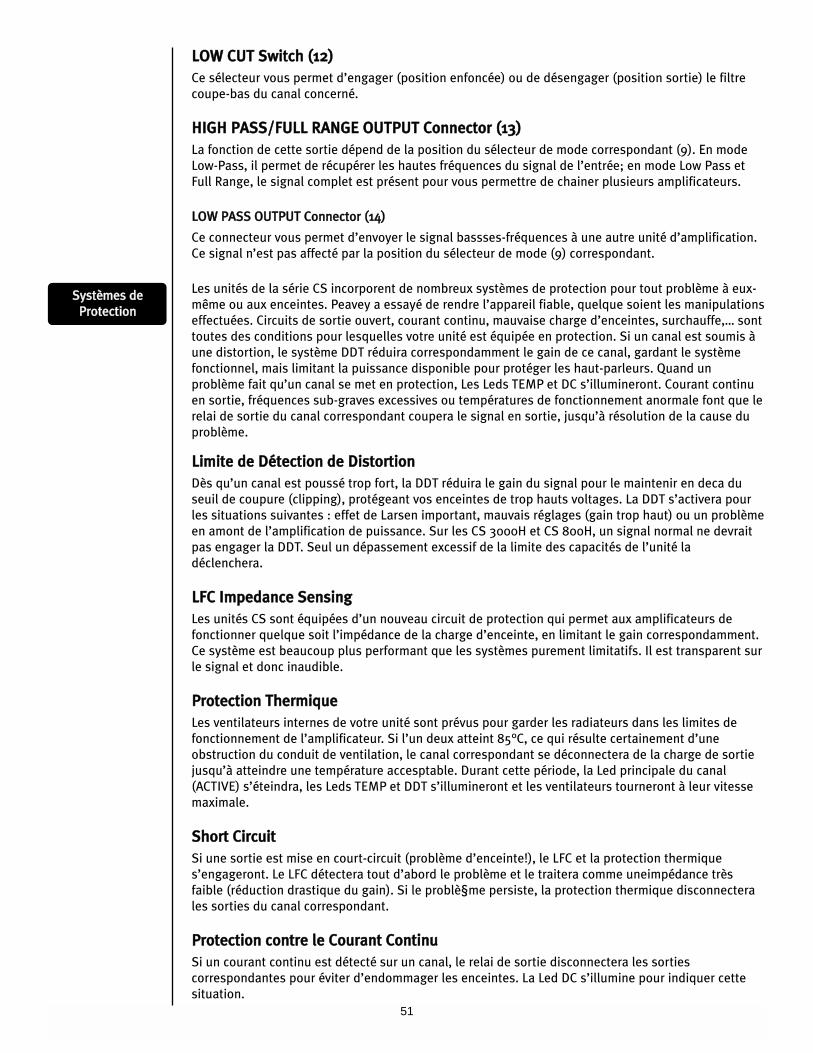
51
LLOOWW CCUUTT SSwwiittcchh ((1122))
Ce sélecteur vous permet d’engager (position enfoncée) ou de désengager (position sortie) le filtre
coupe-bas du canal concerné.
HHIIGGHH PPAASSSS//FFUULLLL RRAANNGGEE OOUUTTPPUUTT CCoonnnneeccttoorr ((1133))
La fonction de cette sortie dépend de la position du sélecteur de mode correspondant (9). En mode
Low-Pass, il permet de récupérer les hautes fréquences du signal de l’entrée; en mode Low Pass et
Full Range, le signal complet est présent pour vous permettre de chainer plusieurs amplificateurs.
LLOOWW PPAASSSS OOUUTTPPUUTT CCoonnnneeccttoorr ((1144))
Ce connecteur vous permet d’envoyer le signal bassses-fréquences à une autre unité d’amplification.
Ce signal n’est pas affecté par la position du sélecteur de mode (9) correspondant.
Les unités de la série CS incorporent de nombreux systèmes de protection pour tout problème à eux-
même ou aux enceintes. Peavey a essayé de rendre l’appareil fiable, quelque soient les manipulations
effectuées. Circuits de sortie ouvert, courant continu, mauvaise charge d’enceintes, surchauffe,… sont
toutes des conditions pour lesquelles votre unité est équipée en protection. Si un canal est soumis à
une distortion, le système DDT réduira correspondamment le gain de ce canal, gardant le système
fonctionnel, mais limitant la puissance disponible pour protéger les haut-parleurs. Quand un
problème fait qu’un canal se met en protection, Les Leds TEMP et DC s’illumineront. Courant continu
en sortie, fréquences sub-graves excessives ou températures de fonctionnement anormale font que le
relai de sortie du canal correspondant coupera le signal en sortie, jusqu’à résolution de la cause du
problème.
LLiimmiittee ddee DDéétteeccttiioonn ddee DDiissttoorrttiioonn
Dès qu’un canal est poussé trop fort, la DDT réduira le gain du signal pour le maintenir en deca du
seuil de coupure (clipping), protégeant vos enceintes de trop hauts voltages. La DDT s’activera pour
les situations suivantes : effet de Larsen important, mauvais réglages (gain trop haut) ou un problème
en amont de l’amplification de puissance. Sur les CS 3000H et CS 800H, un signal normal ne devrait
pas engager la DDT. Seul un dépassement excessif de la limite des capacités de l’unité la
déclenchera.
LLFFCC IImmppeeddaannccee SSeennssiinngg
Les unités CS sont équipées d’un nouveau circuit de protection qui permet aux amplificateurs de
fonctionner quelque soit l’impédance de la charge d’enceinte, en limitant le gain correspondamment.
Ce système est beaucoup plus performant que les systèmes purement limitatifs. Il est transparent sur
le signal et donc inaudible.
PPrrootteeccttiioonn TThheerrmmiiqquuee
Les ventilateurs internes de votre unité sont prévus pour garder les radiateurs dans les limites de
fonctionnement de l’amplificateur. Si l’un deux atteint 85°C, ce qui résulte certainement d’une
obstruction du conduit de ventilation, le canal correspondant se déconnectera de la charge de sortie
jusqu’à atteindre une température accesptable. Durant cette période, la Led principale du canal
(ACTIVE) s’éteindra, les Leds TEMP et DDT s’illumineront et les ventilateurs tourneront à leur vitesse
maximale.
SShhoorrtt CCiirrccuuiitt
Si une sortie est mise en court-circuit (problème d’enceinte!), le LFC et la protection thermique
s’engageront. Le LFC détectera tout d’abord le problème et le traitera comme uneimpédance très
faible (réduction drastique du gain). Si le problè§me persiste, la protection thermique disconnectera
les sorties du canal correspondant.
PPrrootteeccttiioonn ccoonnttrree llee CCoouurraanntt CCoonnttiinnuu
Si un courant continu est détecté sur un canal, le relai de sortie disconnectera les sorties
correspondantes pour éviter d’endommager les enceintes. La Led DC s’illumine pour indiquer cette
situation.
SSyyssttèèmmeess ddee
PPrrootteeccttiioonn
52
PPrrootteeccttiioonn ddee MMiissee SSoouuss//HHoorrss TTeennssiioonn
A l’allumage, votre unité se mettra toujours en mode de protection, avec les sorties déconnectées
pour a peu près 4 secondes (temps de stabilisation des composants). La Led DDT s’illumine pour vous
indiquer cet état. En cas de mise hors tension, les sorties se disconnectent immédiatement pour
éviter tout bruit parasite dans les enceintes.
SSyyssttèèmmee RRaammppUUpp™™ ((ccoonnttrrôôllee ddee mmoonnttééee eenn ppuuiissssaannccee))
Dès que votre unité est mise sous tension ou après qu’une protection se désengage, le circuit
RampUp™ est activé. Le gain du signal est graduellemnt augmenté jusqu’à la valeur du contrôle du
canal correspondant. Ce système présente le majeur avantage d’éviter les soudaines montées en
puissance, prolongeant la durée de vie de votre système d’enceintes.
PPrrootteeccttiioonn ddeess HHaauutt--PPaarrlleeuurrss
Tous les haut-parleurs ont des limites de fonctionnement, thermiques et physiques qu’il faut
respecter. Trop de puissance, signal non-étudié pour le dit haut-parleur (non respect des fréquences
admissibles), ondes limitées (clip) causant un effet d’écrètage et courant continu peuvent leur cuser
des dommages irrémédiables. Les unités CS3000H protègent automatiquement les enceintes d’un
courant continu ou d’une sub-fréquence trop prononcée. Les enceintes médium et aigues,
particulièrement les moteurs de compression sont très sensibles aux surpuissance occasionnelles, ou
aux fréquences trop graves, qui peuvent les endommager très facilement. Prétez une attention toute
particulière aux connections quand vous travaillez sur ces matériels. Assurez vous que la capacité de
puissance (puissance peak) de votre amplificateur ne dépasse pas la puissance admissible de vos
composants.
Un système de fusible peut être utilisé pour limiter la puissance délivrée à une enceinte. Ils ne
représentent pas la solution idéale car ils sont à remplacer après chaque dépassement, et contrôle
plus l’intensité que le voltage d’un signal. De nombreux fusibles ont de plus des valeurs de résistance
non négligeables et risquent donc de détériorer le signal de part l’énergie perdue (qui ne sera
certainement pas uniforme sur les fréquences). Si vous optez pour un système de protection
d’enceintes à fusibles, consultez le fabricant des enceintes pour connaitre les meilleures valeurs de
fusible (temps de réponse,…) à utiliser.
N’envoyez pas de signal de fréquences plus graves que ce que l’enceinte réceptrice peut recevoir.
Vous pourriez endommager votre haut-parleur même à moyenne puissance. Consultez les
caractéristiques de vos enceintes pour déterminer la bande du signal à leur envoyer.
MMaaiinntteennaannccee eett RReessppoonnssaabbiilliittéé dd’’UUttiilliissaatteeuurr
Les amplificateurs CS ne demande pas de maintenance particulière et ne devrait jamais nécessiter de
réglages internes tout au long de sa durée de vie. Il est de votre responsabilité de lire attentivement
les messages de précaution et d’utiliser correctement votre unité. Votre amplificateur est de forte
puissance et travaille avec des tensions qui peuvent être fatales à l’homme. De plus, de nombreuses
enceintes peuvent être gravement endommagées par une surpuissance. Lisez attentivement la
section ‘Protection des Haut-Parleur’ et renseignez vous sur les capacité et fréquences admissibles de
vos enceintes.
53
GGlloossssaaiirree
Stereo: Musique composé de deux signaux indépendants (droite et gauche)
Mono: Musique composé d’un seul signal
Crossover: Unité électronique permettant de séparer un signal en fonction de sa fréquence. Les deux signaux ainsi
obtenus comprennent pour l’un les bassses fréquences, pour l’autre les hautes fréquences.
Bi-amp: Utilisation d’un filtre actif (Crossover) pour séparer le signal, puis d’amplificateurs et d’enceintes dédiés à
chaques parties de ce signal.
Full Range: Un signal comprenant toutes les fréquences en même temps.
Program: Le signal entrant dans l’unité de puissance
Hi-pass: Filtre permettant aux hautes fréquences de passer, bloquant les basses fréquences du signal.
Low-pass: Filtre permettant aux basses fréquences de passer, bloquant les hautes fréquences du signal.
Mid/High: Eneintes acceptant un signal dépourvu de sa partie basses fréquences
Sub: Enceintes n’acceptant que les signaux de basses fréquences.
Parallel: Montazge électrique permettant d’envoyer le même signal aux deux entrées/enceintes..

54
SSeettuupp--AAnnwweeiissuunnggeenn
SStteerreeoo OOppeerraattiioonn
1. Set AAMMPP MMOODDEE switch to SSTTEERREEOO.
2. Set the A and B channel AAMMPP FFUUNNCCTTIIOONN switches and to FFUULLLL RRAANNGGEE.
3. Connect the Left and Right program signal to the A and B channel inputs: and .
4. Connect the A and B channel speaker outputs and to the loudspeaker full range inputs.
1
2 3
4 5
7 8
BBrriiddggee MMooddee OOppeerraattiioonn
1. Set AAMMPP MMOODDEE switch to BBRRIIDDGGEE.
2. Connect the program signal to the A channel input .
3. Connect the loudspeaker across the two RED binding posts on the amplifier outputs . The A channel is positive
and the B channel is negative or between th 1+ and 2+ pins of the A channel Speakon connector (the 1+ positive
and the 2+ pin is negative).
1
4
97
TTwwoo CChhaannnneell PPaarraalllleell OOppeerraattiioonn ((FFuullll RRaannggee))
1. Set AAMMPP MMOODDEE switch to SSTTEERREEOO.
2. Set the A and B channel AAMMPP FFUUNNCCTTIIOONN switches and to FFuullll RRaannggee .
3. Connect the program signal to the A channel input .
4. Plug a short shielded cable into the A HHIIGGHH PPAASSSS//FFUULLLL RRAANNGGEE output .
5. Connect the other end of the same cable to the B channel input .
6. Connect the A and B channel speaker outputs and . to the loudspeaker full range inputs.
1
2 3
4
6
5
7 8
4 2 6
87 9
1 5 3
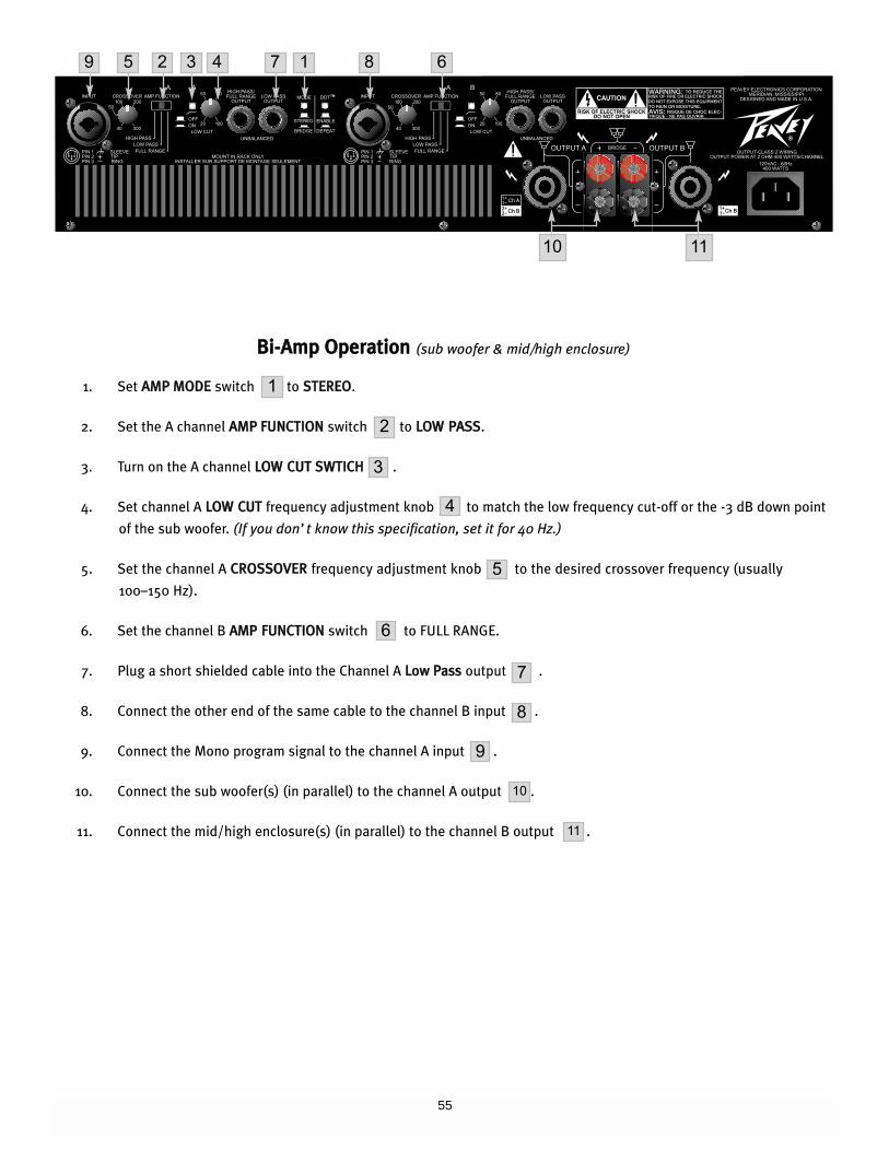
55
BBii--AAmmpp OOppeerraattiioonn (sub woofer & mid/high enclosure)
1. Set AAMMPP MMOODDEE switch to SSTTEERREEOO.
2. Set the A channel AAMMPP FFUUNNCCTTIIOONN switch to LLOOWW PPAASSSS.
3. Turn on the A channel LLOOWW CCUUTT SSWWTTIICCHH .
4. Set channel A LLOOWW CCUUTT frequency adjustment knob to match the low frequency cut-off or the -3 dB down point
of the sub woofer. (If you don’t know this specification‚ set it for 40 Hz.)
5. Set the channel A CCRROOSSSSOOVVEERR frequency adjustment knob to the desired crossover frequency (usually
100–150 Hz).
6. Set the channel B AAMMPP FFUUNNCCTTIIOONN switch to FULL RANGE.
7. Plug a short shielded cable into the Channel A LLooww PPaassss output .
8. Connect the other end of the same cable to the channel B input .
9. Connect the Mono program signal to the channel A input .
10. Connect the sub woofer(s) (in parallel) to the channel A output .
11. Connect the mid/high enclosure(s) (in parallel) to the channel B output .
1
9
2
4
5
6
7
8
9
10
11
3
5 3 4 7 1 8 6
10 11
2
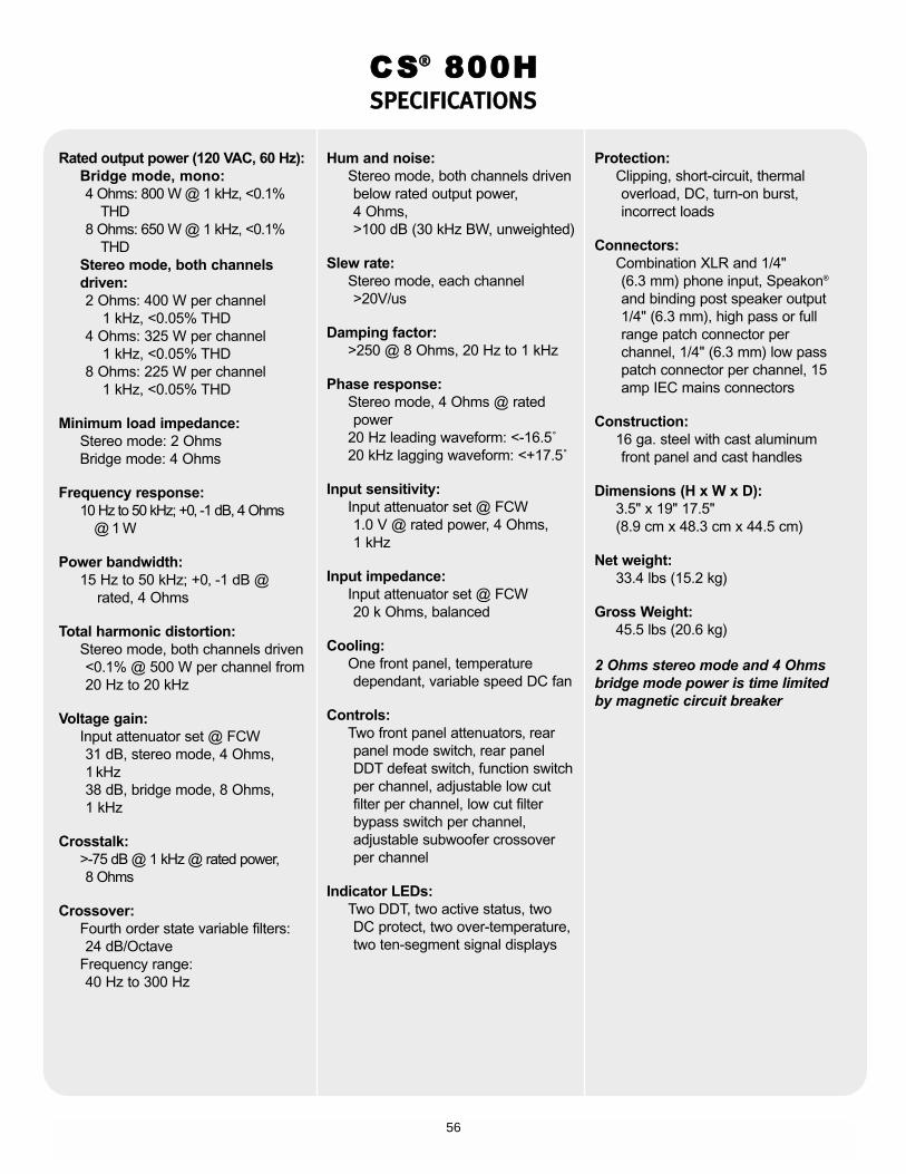
56
Rated output power (120 VAC, 60 Hz):Bridge mode, mono:4 Ohms: 800 W @ 1 kHz, <0.1%
THD8 Ohms: 650 W @ 1 kHz, <0.1%
THDStereo mode, both channelsdriven:2 Ohms: 400 W per channel
1 kHz, <0.05% THD4 Ohms: 325 W per channel
1 kHz, <0.05% THD8 Ohms: 225 W per channel
1 kHz, <0.05% THD
Minimum load impedance:Stereo mode: 2 OhmsBridge mode: 4 Ohms
Frequency response:10 Hz to 50 kHz; +0‚ -1 dB, 4 Ohms
@ 1 W
Power bandwidth:15 Hz to 50 kHz; +0‚ -1 dB @
rated, 4 Ohms
Total harmonic distortion:Stereo mode, both channels driven<0.1% @ 500 W per channel from 20 Hz to 20 kHz
Voltage gain:Input attenuator set @ FCW 31 dB, stereo mode, 4 Ohms,1 kHz 38 dB, bridge mode, 8 Ohms, 1 kHz
Crosstalk:>-75 dB @ 1 kHz @ rated power, 8 Ohms
Crossover:Fourth order state variable filters: 24 dB/Octave
Frequency range:40 Hz to 300 Hz
Hum and noise:Stereo mode, both channels drivenbelow rated output power, 4 Ohms, >100 dB (30 kHz BW, unweighted)
Slew rate:Stereo mode, each channel>20V/us
Damping factor:>250 @ 8 Ohms, 20 Hz to 1 kHz
Phase response:Stereo mode, 4 Ohms @ rated power
20 Hz leading waveform: <-16.5˚20 kHz lagging waveform: <+17.5˚
Input sensitivity:Input attenuator set @ FCW1.0 V @ rated power, 4 Ohms, 1 kHz
Input impedance:Input attenuator set @ FCW20 k Ohms, balanced
Cooling:One front panel, temperature dependant, variable speed DC fan
Controls:Two front panel attenuators‚ rear panel mode switch‚ rear panelDDT defeat switch, function switchper channel, adjustable low cutfilter per channel, low cut filterbypass switch per channel,adjustable subwoofer crossoverper channel
Indicator LEDs:Two DDT, two active status, two DC protect, two over-temperature,two ten-segment signal displays
Protection:Clipping, short-circuit, thermal overload, DC, turn-on burst,incorrect loads
Connectors:Combination XLR and 1/4" (6.3 mm) phone input, Speakon®
and binding post speaker output1/4" (6.3 mm), high pass or fullrange patch connector perchannel, 1/4" (6.3 mm) low passpatch connector per channel, 15amp IEC mains connectors
Construction:16 ga. steel with cast aluminum front panel and cast handles
Dimensions (H x W x D):3.5" x 19" 17.5"(8.9 cm x 48.3 cm x 44.5 cm)
Net weight:33.4 lbs (15.2 kg)
Gross Weight:45.5 lbs (20.6 kg)
2 Ohms stereo mode and 4 Ohmsbridge mode power is time limitedby magnetic circuit breaker
CS®® 800HSSPPEECCIIFFIICCAATTIIOONNSS

57
NNOOTTEESS::

58
NNOOTTEESS::
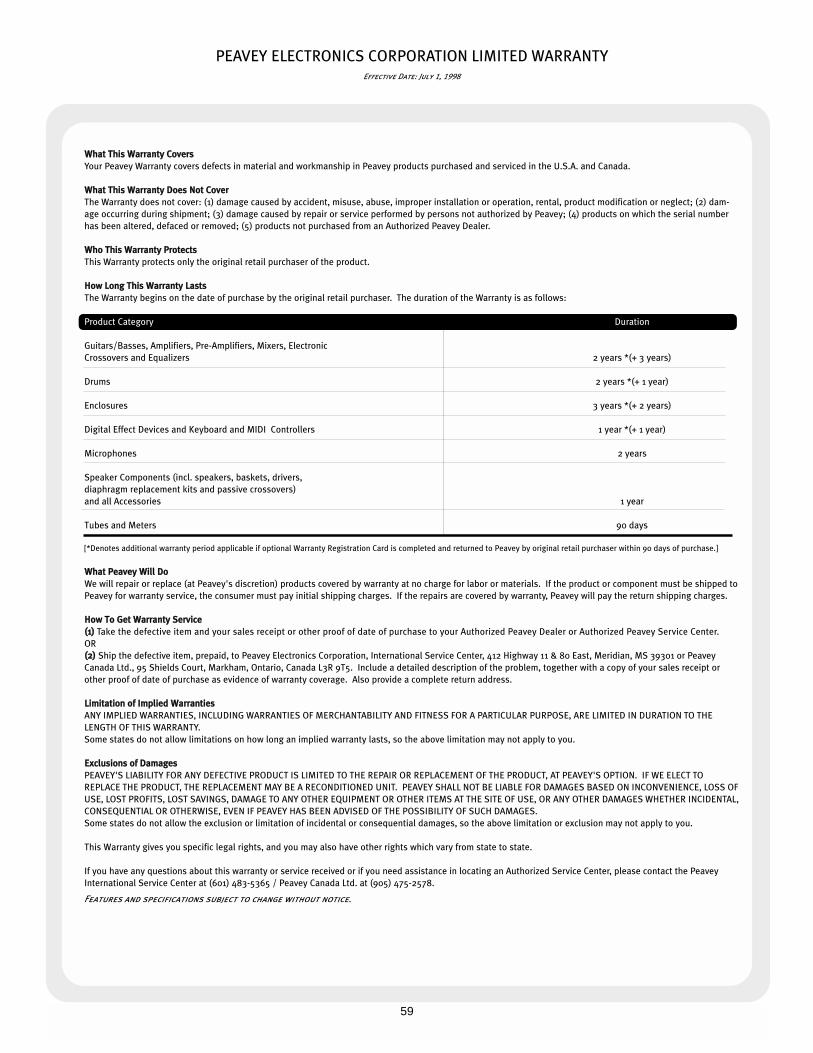
59
PEAVEY ELECTRONICS CORPORATION LIMITED WARRANTYEffective Date: July 1, 1998
WWhhaatt TThhiiss WWaarrrraannttyy CCoovveerrss
Your Peavey Warranty covers defects in material and workmanship in Peavey products purchased and serviced in the U.S.A. and Canada.
WWhhaatt TThhiiss WWaarrrraannttyy DDooeess NNoott CCoovveerr
The Warranty does not cover: (1) damage caused by accident, misuse, abuse, improper installation or operation, rental, product modification or neglect; (2) dam-
age occurring during shipment; (3) damage caused by repair or service performed by persons not authorized by Peavey; (4) products on which the serial number
has been altered, defaced or removed; (5) products not purchased from an Authorized Peavey Dealer.
WWhhoo TThhiiss WWaarrrraannttyy PPrrootteeccttss
This Warranty protects only the original retail purchaser of the product.
HHooww LLoonngg TThhiiss WWaarrrraannttyy LLaassttss
The Warranty begins on the date of purchase by the original retail purchaser. The duration of the Warranty is as follows:
Product Category Duration
Guitars/Basses, Amplifiers, Pre-Amplifiers, Mixers, Electronic
Crossovers and Equalizers 2 years *(+ 3 years)
Drums 2 years *(+ 1 year)
Enclosures 3 years *(+ 2 years)
Digital Effect Devices and Keyboard and MIDI Controllers 1 year *(+ 1 year)
Microphones 2 years
Speaker Components (incl. speakers, baskets, drivers,
diaphragm replacement kits and passive crossovers)
and all Accessories 1 year
Tubes and Meters 90 days
[*Denotes additional warranty period applicable if optional Warranty Registration Card is completed and returned to Peavey by original retail purchaser within 90 days of purchase.]
WWhhaatt PPeeaavveeyy WWiillll DDoo
We will repair or replace (at Peavey's discretion) products covered by warranty at no charge for labor or materials. If the product or component must be shipped to
Peavey for warranty service, the consumer must pay initial shipping charges. If the repairs are covered by warranty, Peavey will pay the return shipping charges.
HHooww TToo GGeett WWaarrrraannttyy SSeerrvviiccee
((11)) Take the defective item and your sales receipt or other proof of date of purchase to your Authorized Peavey Dealer or Authorized Peavey Service Center.
OR
((22)) Ship the defective item, prepaid, to Peavey Electronics Corporation, International Service Center, 412 Highway 11 & 80 East, Meridian, MS 39301 or Peavey
Canada Ltd., 95 Shields Court, Markham, Ontario, Canada L3R 9T5. Include a detailed description of the problem, together with a copy of your sales receipt or
other proof of date of purchase as evidence of warranty coverage. Also provide a complete return address.
LLiimmiittaattiioonn ooff IImmpplliieedd WWaarrrraannttiieess
ANY IMPLIED WARRANTIES, INCLUDING WARRANTIES OF MERCHANTABILITY AND FITNESS FOR A PARTICULAR PURPOSE, ARE LIMITED IN DURATION TO THE
LENGTH OF THIS WARRANTY.
Some states do not allow limitations on how long an implied warranty lasts, so the above limitation may not apply to you.
EExxcclluussiioonnss ooff DDaammaaggeess
PEAVEY'S LIABILITY FOR ANY DEFECTIVE PRODUCT IS LIMITED TO THE REPAIR OR REPLACEMENT OF THE PRODUCT, AT PEAVEY'S OPTION. IF WE ELECT TO
REPLACE THE PRODUCT, THE REPLACEMENT MAY BE A RECONDITIONED UNIT. PEAVEY SHALL NOT BE LIABLE FOR DAMAGES BASED ON INCONVENIENCE, LOSS OF
USE, LOST PROFITS, LOST SAVINGS, DAMAGE TO ANY OTHER EQUIPMENT OR OTHER ITEMS AT THE SITE OF USE, OR ANY OTHER DAMAGES WHETHER INCIDENTAL,
CONSEQUENTIAL OR OTHERWISE, EVEN IF PEAVEY HAS BEEN ADVISED OF THE POSSIBILITY OF SUCH DAMAGES.
Some states do not allow the exclusion or limitation of incidental or consequential damages, so the above limitation or exclusion may not apply to you.
This Warranty gives you specific legal rights, and you may also have other rights which vary from state to state.
If you have any questions about this warranty or service received or if you need assistance in locating an Authorized Service Center, please contact the Peavey
International Service Center at (601) 483-5365 / Peavey Canada Ltd. at (905) 475-2578.
Features and specifications subject to change without notice.

Features and specifications subject to change without notice.
Peavey Electronics Corporation • 711 A Street • Meridian • MS • 39301
(601) 483-5365 • FAX (601) 486-1278 • www.peavey.com
©2003 Printed in the U.S.A. 6/0380304955