JOHNSON MATTHEY TECHNOLOGY REVIEW · PDF fileJOHNSON MATTHEY TECHNOLOGY REVIEW ... the fi...
13
www.technology.matthey.com JOHNSON MATTHEY TECHNOLOGY REVIEW http://dx.doi.org/10.1595/205651316X691230 Johnson Matthey Technol. Rev., 2016, 60, (2), 132–144 132 © 2016 Johnson Matthey Applications of Neutron Scattering in Catalysis Where atoms are and how they move By Stewart F. Parker* ISIS Facility, STFC Rutherford Appleton Laboratory, Chilton, Didcot, OX11 0QX, UK and UK Catalysis Hub, Research Complex at Harwell, STFC Rutherford Appleton Laboratory, Chilton, Didcot, Oxfordshire OX11 0FA, UK Paul Collier § Johnson Matthey Technology Centre, Blounts Court, Sonning Common, Reading, RG4 9NH, UK Email: *[email protected]; § [email protected] Neutron scattering is a severely underused technique for studies of catalysts. In this review we describe how and why neutrons are useful to catalysis. We illustrate the range of systems that have been studied by both elastic and inelastic neutron scattering. These range from structural studies of adsorbates in zeolites to determination of the structure of surface adsorbates, characterisation of nanoparticles, the measurement and mechanism of diffusion and spectroscopic characterisation of adsorbed species. We conclude with how to access neutron facilities and some future prospects for the application of these techniques to industrially useful materials. Why Neutron Scattering? Neutron scattering is undoubtedly a severely underutilised capability in catalysis research. This is probably for two main reasons: there is a lack of understanding of what the technique can provide and it is seen as being the province of purely academic research, largely for condensed matter physics. These perceptions are not correct: there is a wealth of information that can be provided to the chemist, surface scientist and other specialisms within both academic and industrially focused research. There are a small number of centres for neutron scattering worldwide, since the production of sufficient neutrons for useful science requires highly specialised facilities. The aim of this review is to show that even within the constraint of a limited number of facilities, neutron scattering can usefully contribute to many areas of catalysis that range across structure determination at the micro- to the nanoscale and atomic and molecular dynamics from the femtosecond (vibrational spectroscopy) to the sub-microsecond (diffusion) timescale. Neutron Properties and their Applications The usefulness of neutron scattering arises from the properties of the neutron, which is an uncharged particle of mass 1.00866 amu (almost the same as the hydrogen atom 1 H, 1.00782) with a magnetic moment. Neutrons are scattered by the atomic nuclei of the sample and, since the nucleus of an atom is only ~0.1% of the diameter of the atom, to a neutron most of a material is empty space. Hence neutrons only interact weakly with matter and as a result are highly penetrating; for example the attenuation at 1.81 Å (which corresponds to the peak flux from a research reactor) by 1 mm of aluminium is less than 1%.
Transcript of JOHNSON MATTHEY TECHNOLOGY REVIEW · PDF fileJOHNSON MATTHEY TECHNOLOGY REVIEW ... the fi...

www.technology.matthey.comJOHNSON MATTHEY TECHNOLOGY REVIEW
http://dx.doi.org/10.1595/205651316X691230 Johnson Matthey Technol. Rev., 2016, 60, (2), 132–144
132 © 2016 Johnson Matthey
Applications of Neutron Scattering in CatalysisWhere atoms are and how they move
By Stewart F. Parker* ISIS Facility, STFC Rutherford Appleton Laboratory, Chilton, Didcot, OX11 0QX, UKandUK Catalysis Hub, Research Complex at Harwell, STFC Rutherford Appleton Laboratory, Chilton, Didcot, Oxfordshire OX11 0FA, UK
Paul Collier§ Johnson Matthey Technology Centre, Blounts Court, Sonning Common, Reading, RG4 9NH, UK
Email: *[email protected]; §[email protected]
Neutron scattering is a severely underused technique for studies of catalysts. In this review we describe how and why neutrons are useful to catalysis. We illustrate the range of systems that have been studied by both elastic and inelastic neutron scattering. These range from structural studies of adsorbates in zeolites to determination of the structure of surface adsorbates, characterisation of nanoparticles, the measurement and mechanism of diffusion and spectroscopic characterisation of adsorbed species. We conclude with how to access neutron facilities and some future prospects for the application of these techniques to industrially useful materials.
Why Neutron Scattering?
Neutron scattering is undoubtedly a severely underutilised capability in catalysis research. This
is probably for two main reasons: there is a lack of understanding of what the technique can provide and it is seen as being the province of purely academic research, largely for condensed matter physics. These perceptions are not correct: there is a wealth of information that can be provided to the chemist, surface scientist and other specialisms within both academic and industrially focused research. There are a small number of centres for neutron scattering worldwide, since the production of sufficient neutrons for useful science requires highly specialised facilities. The aim of this review is to show that even within the constraint of a limited number of facilities, neutron scattering can usefully contribute to many areas of catalysis that range across structure determination at the micro- to the nanoscale and atomic and molecular dynamics from the femtosecond (vibrational spectroscopy) to the sub-microsecond (diffusion) timescale.
Neutron Properties and their Applications
The usefulness of neutron scattering arises from the properties of the neutron, which is an uncharged particle of mass 1.00866 amu (almost the same as the hydrogen atom 1H, 1.00782) with a magnetic moment. Neutrons are scattered by the atomic nuclei of the sample and, since the nucleus of an atom is only ~0.1% of the diameter of the atom, to a neutron most of a material is empty space. Hence neutrons only interact weakly with matter and as a result are highly penetrating; for example the attenuation at 1.81 Å (which corresponds to the peak fl ux from a research reactor) by 1 mm of aluminium is less than 1%.
133 © 2016 Johnson Matthey
http://dx.doi.org/10.1595/205651316X691230 Johnson Matthey Technol. Rev., 2016, 60, (2)
For neutron diffraction studies it is straightforward to study light elements in the presence of heavy ones. The scattering cross section is both atom and isotope dependent, Figure 1, and is not a monotonic function of atomic number as it is for X-ray scattering. Hydrogen-in-metal systems are perhaps the most important example of systems which are ideal for study using neutron techniques, but it is also a valuable way to determine the precise location of oxygen in heavy metal oxides in fi elds ranging from high-temperature superconductors to oxide ion conductors in fuel cells.
Bond distances are generally more accurate from neutron scattering data than from X-ray techniques, particularly for bonds involving hydrogen, since the maximum electron density is not located at the atomic position but is displaced towards the heavier atom. Thus C–H and O–H distances measured by X-ray diffraction are typically 0.1 Å shorter than those measured by neutron diffraction.
It is also possible to distinguish elements that are adjacent in the periodic table, such as Al3+ and Si4+, as commonly found in microporous materials. These elements have identical scattering power for X-rays (since they have the same number of electrons) but different neutron cross sections, 1.503 vs. 2.167 barn (1 barn = 1 10–28 m2) respectively, hence providing contrast.
The atomic nucleus acts as a point-like scatterer, unlike the electron cloud, which is of fi nite size compared to the wavelengths used. The consequence of this is that the neutron cross section is independent of the scattering angle, 2θ, in contrast to the X-ray case where the X-ray cross section has a form factor
that decreases with increasing scattering angle. Thus the smaller d spacing information is relatively better determined in a neutron experiment compared to a similar X-ray experiment. This results in more precise atomic thermal parameters being determined from powder neutron data than from the powder X-ray data.
The most striking difference in cross section occurs for 1H and 2H, hydrogen and deuterium: coh = 1.76 (1H), 5.59 (2H) barn, inc = 80.27 (1H), 2.05 (2H) barn (coh = coherent scattering cross section, inc = incoherent scattering cross section). Hence hydrogen is overwhelmingly an incoherent scatterer while deuterium is primarily a coherent scatterer. Coherent scattering gives information on long range properties such as structure while incoherent scattering is a local probe. The neutron may be scattered without a change in energy (elastic scattering) as in diffraction, or there may be exchange of energy between the sample and the neutron (inelastic scattering). The latter may be coherent or incoherent, but for any material containing hydrogen, the incoherent scattering dominates. Since much of catalysis involves the transfer of hydrogen from reactant to product, the sensitivity to hydrogen is a major advantage of the technique. However, for structural studies it may be necessary to use deuterated materials, since the incoherent scattering from hydrogen results in a signifi cant background that complicates the data analysis. For inelastic scattering, it is only the exceptionally large value of inc that makes catalysis studies feasible.
In short, neutron scattering can be summarised as: “where atoms are and how they move”.
Elastic Scattering – Where Atoms Are
Elastic scattering of neutrons covers length scales that span from 1 to 5000 Å. This ranges from the atomic scale for structure determination to typical sizes of colloids. The investigation of structure is the major use of neutrons in this area, particularly by powder diffraction. The location of n-heptane in silicalite-1 (1) provides an example of what can be achieved. This system shows an infl ection in the adsorption isotherm at a loading near four molecules per unit cell that has been ascribed to a commensurate freezing of n-heptane in the sinusoidal channels of silicalite-1. To investigate the unusual behaviour, the adsorption of C7D16 was followed in situby powder neutron diffraction. (Deuterated heptane was used to reduce the incoherent background). The results show that the straight channels are fi rst fi lled, then near
Sc
Fig. 1. Neutron scattering cross section as a function of atomic number
Cro
ss s
ectio
n, b
arn
0 10 20 30 40 50Atomic number
806040
20
10
0
D
N
Ni
Fe
Cl
Xe
H

134 © 2016 Johnson Matthey
http://dx.doi.org/10.1595/205651316X691230 Johnson Matthey Technol. Rev., 2016, 60, (2)
four molecules per unit cell, the molecules also fi ll the sinusoidal channels, Figure 2. Thus the diffraction data show that the infl ection point in the isotherm is due to self-blocking of the channels at junctions.
Diffraction methods are well-suited to operando measurements and this is already utilised for neutron diffraction studies of batteries (2) and proton conductors (3). Studies of catalysts are also feasible as shown by a recent study of the activation and subsequent working of a commercial Cu/ZnO/Al2O3 methanol synthesis catalyst (4, 5). Due to their pyrophoric nature, commercial Cu/ZnO/Al2O3 catalysts are prepared in the completely oxidised form as CuO/ZnO/Al2O3 and the fi rst step in methanol synthesis is activation of the catalyst by reduction of CuO to metallic Cu. The activation process is shown in Figure 3 following the reduction of CuO and the growth of Cu. It has been proposed that defects play an important role in the active Cu phase but Cu would be expected to be mobile enough under the reaction conditions, T = 493–573 K, P = 3.5–10 MPa, for these to anneal out. In situ neutron diffraction was able to show that the nanostructured Cu generated by reduction of the CuO precursor has a high concentration of stacking faults and also that they were stable under industrial methanol synthesis conditions (5).
Pair distribution function (PDF) analysis or total scattering analysis (6) is a well-established technique for the structural characterisation of poorly- or non-crystalline materials including nanoparticles. Figure 4 shows a comparison between the
(a) (b)
Fig. 2. Locations of C7D16 molecules within silicalite-1 obtained from Rietveld refi nement of neutron diffraction patterns. At low loading, <4 molecules per unit cell only the straight channels are occupied (black molecules) while at high loading >4 molecules per unit cell both the straight and the sinusoidal channels are occupied (black and green molecules respectively). (a) View along the [010] direction; (b) view along the [001] direction. Reprinted with permission from (1). Copyright (2007) American Chemical Society
b
a
a
c
Fig. 3. Reduction procedure of a commercial Cu/ZnO/Al2O3 catalyst from 301 K to 523 K in D2. Normalised integrated intensities of the CuO(11–1) and Cu(111) peaks correlated with: (a) the catalyst bed temperature; and (b) the effluent gas composition (m/z = 4 = D2, m/z = 20 = D2O) during isobaric reduction. (The missing ion–current between 130 and 140 min is an experimental artefact). Reproduced from (4) with permission of Elsevier
N
orm
alis
ed in
tegr
al in
tens
ity
1.2
1.0
0.8
0.6
0.4
0.2
0
–0.2
CuO(11-1)Cu(111)T, ºC
m/z = 4m/z = 20
300
250
200
150
100
50
0
Bed tem
perature, ºC
50 100 150 200 250Time, min
(a)
(b)
Nor
mal
ised
ion
curr
ent,
au

135 © 2016 Johnson Matthey
http://dx.doi.org/10.1595/205651316X691230 Johnson Matthey Technol. Rev., 2016, 60, (2)
experimental data for hydrous palladium oxide, PdO·H2O, (a model system for CO oxidation by an automotive three-way catalyst) and the data generated from a simulation consisting of ~18 Å nanoparticle of PdO (7). The alternative formulation as Pd(OH)2 is clearly untenable and the simulation shows that the material has a core of poorly crystalline PdO.
The PDF approach has been extended to enable the local structure of adsorbed species in zeolites (8) and on surfaces (9) to be determined. The advantage of the method is that it does not require long range order and that bond distances can be obtained by inspection of the radial distribution function. However, the method greatly benefi ts from input by ab initio methods as was done for acetylene on nickel ion exchanged zeolite NaY (8) and hydrogen on Raney nickel (9). Figure 5shows a comparison of the experimental data for hydrogen on Raney Ni and the radial distribution function generated from a periodic density functional theory calculation of hydrogen on Ni(111) (for an fcc metal, the 111 face is the lowest energy surface so is expected to predominate on nanoparticles). It can be seen that the agreement is excellent. The extension of the method to more complicated systems involving chemisorbed organic species is an active area of investigation.
Inelastic Scattering – How Atoms Move
As shown in Figure 6, inelastic scattering covers a vast range of length and time scales. For catalysis, the most relevant are quasielastic neutron scattering (QENS) which probes whole-body motions (such as diffusion) on and within materials and neutron vibrational spectroscopy or inelastic neutron scattering (INS), which probes the motion of atoms and molecules within a material.
Quasielastic scattering (10) is a very low energy inelastic process which usually manifests itself as a broadening of the elastic line and is most commonly the result of diffusional (translational or rotational) motion of atoms. Translational and rotational diffusion occur simultaneously but on different timescales. The energy resolution of a spectrometer, ΔE, and the timescale, , of the motion are related by the Heisenberg uncertainty principle: ΔE ≈ h/2. Thus resolution and timescale are inversely related and the slower the motion, the higher the required resolution. QENS spans the range 10–11 ≤ ≤ 10–7 s, which requires 10–5 ≤ ΔE ≤ 10–8 cm–1.
Fig. 4. The neutron diffraction differential correlation function, DN(r), for as received hydrous palladium oxide (red). The blue curve is a simulated correlation function based on a model of a 18 Å nanoparticle of PdO. Reprinted with permission from (7). Copyright (2010) American Chemical Society
Dis
tinct
sca
tterin
g, iN
(Q),
barn
s at
om–1
ste
radi
an–1
0
0 5 10 15 20Momentum transfer, Q, Å–1
Fig. 5. Difference pair distribution function, ΔD(R), for hydrogen on Raney nickel (purple) at room temperature. This is the Fourier transform of the normalised difference of the catalyst before and after addition of hydrogen. (The peak at ~1.00 Å is non-physical and results from a truncation error in the Fourier transform.) Also shown is the pair distribution D(R) function (red) generated from a periodic-DFT calculation of H on Ni(111). The spectrum is abscissa scaled so that the large peaks at 2.54 Å have the same amplitude. No ordinate scaling has been applied, all the distances come directly from the ab initio calculation (9). Reproduced by permission of the Royal Society of Chemistry
D(R
)
0.2
0.1
0
–0.10 1 2 3 4
Distance, Å

136 © 2016 Johnson Matthey
http://dx.doi.org/10.1595/205651316X691230 Johnson Matthey Technol. Rev., 2016, 60, (2)
No single spectrometer can access all of this range and typically three are needed: direct-geometry time-of-fl ight ( ~ 10–11 s), backscattering crystal analyser ( ~ 10–9 s) and neutron spin echo ( ~ 10–7 s).
Understanding the diffusion behaviour of molecules in microporous materials is important for the design of membranes for separations and for catalysts, particularly for applications in the petrochemical industry. QENS is ideally suited for the measurement of diffusion constants in technologically relevant materials (11). The QENS timescales also match those accessible by classical molecular dynamics (MD) simulations which can provide insight into the diffusion mechanism. However, until very recently (12), the agreement between observed and calculated diffusion constants could differ by as much as two-to-three orders of magnitude, Figure 7. The improvement is the result of using fully atomistic models for both adsorbate and framework, adsorbate loadings that match those used experimentally and a fl exible framework that deforms as the molecule moves through the channel.
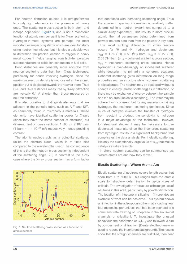
The diffusion of branched alkanes has been much less studied than the n-alkanes. However, an understanding of the diffusion of branched alkanes is crucial to understand the effect of molecular shape on both catalytic cracking and molecular sieving in zeolites. 2-methylpropane (isobutane) is the simplest branched alkane and its diffusion in silicalite has been studied by a variety of experimental and computational methods. The diffusion is suffi ciently slow that the neutron spin echo technique and long MD runs are required. Figure 8(a) shows the neutron spin echo results (13)
compared with fi ts for 3D and 1D diffusion models. This immediately shows that 2-methylpropan e is able to explore both the straight and sinusoidal channels, in contrast to previous results that indicated the molecule was confi ned to the straight channels. The MD results support this conclusion and show that from an initial confi guration where the 2-methylpropane molecules were placed in the large cages at the intersections of the straight and sinusoidal channels, the system evolves to have both types of channel populated, Figure 8(b).
Fig. 6. The time and energy ranges spanned by inelastic neutron scattering
Energy transfer, cm–1 100 101 102 103 104 105 106
Timescale, s 10–7–10–11 10–12 10–13 10–14 10–15 10–16
Length probed, Å >30 10 1 0.1 0.001 0.0001 0.00001
S(Q
,)
Elastic peakQuasi-elastic
Phonons (acoustic mode)
Rotational
Vibrational (optic mode)
Recoil
Electronic
Fig. 7. Diffusion coeffi cients of n-alkanes in silicalite: (♦) MD simulation using simpler models (united atom, rigid lattice); (▲) MD simulations at infi nite dilution; (*) hierarchical simulations (united atom, coarse-grained framework); (○) fully atomistic MD simulation with fl exible lattice; and (□) experimental (QENS) (12). Reproduced by permission of the PCCP Owner Societies
8 10 12 14 16Chain length
Diff
usio
n co
effi c
ient
, m2 s
–1 ×
10–1
0 100
10
1
0.1
0.01
137 © 2016 Johnson Matthey
http://dx.doi.org/10.1595/205651316X691230 Johnson Matthey Technol. Rev., 2016, 60, (2)
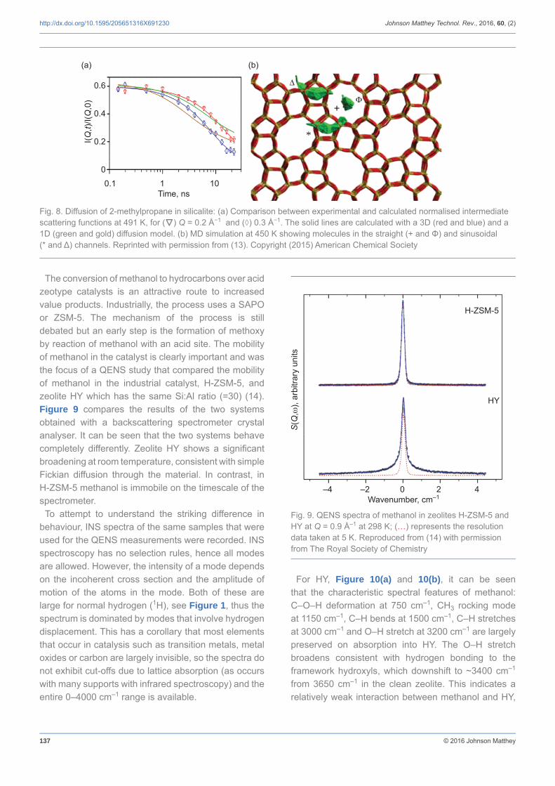
The conversion of methanol to hydrocarbons over acid zeotype catalysts is an attractive route to increased value products. Industrially, the process uses a SAPO or ZSM-5. The mechanism of the process is still debated but an early step is the formation of methoxy by reaction of methanol with an acid site. The mobility of methanol in the catalyst is clearly important and was the focus of a QENS study that compared the mobility of methanol in the industrial catalyst, H-ZSM-5, and zeolite HY which has the same Si:Al ratio (=30) (14). Figure 9 compares the results of the two systems obtained with a backscattering spectrometer crystal analyser. It can be seen that the two systems behave completely differently. Zeolite HY shows a signifi cant broadening at room temperature, consistent with simple Fickian diffusion through the material. In contrast, in H-ZSM-5 methanol is immobile on the timescale of the spectrometer.
To attempt to understand the striking difference in behaviour, INS spectra of the same samples that were used for the QENS measurements were recorded. INS spectroscopy has no selection rules, hence all modes are allowed. However, the intensity of a mode depends on the incoherent cross section and the amplitude of motion of the atoms in the mode. Both of these are large for normal hydrogen (1H), see Figure 1, thus the spectrum is dominated by modes that involve hydrogen displacement. This has a corollary that most elements that occur in catalysis such as transition metals, metal oxides or carbon are largely invisible, so the spectra do not exhibit cut-offs due to lattice absorption (as occurs with many supports with infrared spectroscopy) and the entire 0–4000 cm–1 range is available.
For HY, Figure 10(a) and 10(b), it can be seen that the characteristic spectral features of methanol: C–O–H deformation at 750 cm–1, CH3 rocking mode at 1150 cm–1, C–H bends at 1500 cm–1, C–H stretches at 3000 cm–1 and O–H stretch at 3200 cm–1 are largely preserved on absorption into HY. The O–H stretch broadens consistent with hydrogen bonding to the framework hydroxyls, which downshift to ~3400 cm–1
from 3650 cm–1 in the clean zeolite. This indicates a relatively weak interaction between methanol and HY,
Fig. 8. Diffusion of 2-methylpropane in silicalite: (a) Comparison between experimental and calculated normalised intermediate scattering functions at 491 K, for (▼) Q = 0.2 Å−1 and (◊) 0.3 Å−1. The solid lines are calculated with a 3D (red and blue) and a 1D (green and gold) diffusion model. (b) MD simulation at 450 K showing molecules in the straight (+ and Φ) and sinusoidal (* and Δ) channels. Reprinted with permission from (13). Copyright (2015) American Chemical Society
(a) (b)
I(Q,t)
/I(Q
,0)
0.6
0.4
0.2
00.1 1 10
Time, ns
+
*
Fig. 9. QENS spectra of methanol in zeolites H-ZSM-5 and HY at Q = 0.9 Å–1 at 298 K; (…) represents the resolution data taken at 5 K. Reproduced from (14) with permission from The Royal Society of Chemistry
S(Q
,),
arbi
trary
uni
ts
–4 –2 0 2 4Wavenumber, cm–1
H-ZSM-5
HY

138 © 2016 Johnson Matthey
http://dx.doi.org/10.1595/205651316X691230 Johnson Matthey Technol. Rev., 2016, 60, (2)
allowing free diffusion as seen by QENS. In contrast, in H-ZSM-5, Figure 10(c) and 10(d), while the C–H related modes (rock, bend, stretch) are all present, the C–O–H and Si–O–H deformations and the methanol and framework O–H stretch all disappear upon adsorption of methanol. This indicates that reaction between methanol and the H-ZSM-5 hydroxyls has occurred to generate bound methoxy, Equation (i):
CH3OH + Si–O–H Si–O–CH3 + H2O (i)
The reaction occurs at room temperature, suggesting a very low activation barrier, with water removed in the He/methanol gas stream used to prepare the samples.
On almost any working catalyst that involves reaction of hydrocarbons, over time there is a build-up of a hydrocarbonaceous overlayer, which may be detrimental to the catalyst activity by blocking access to the active sites or may be integral to its operation by controlling the fl ow of reactants to the surface. The overlayers are diffi cult to study with light-based spectroscopies due to strong absorption
and/or fl uorescence. These are irrelevant to INS spectroscopy and it has been used to study the overlayers on Ni/Al2O3 methane reforming catalysts (17–19). As part of the work, a method to quantify and speciate hydrogen on the surface of the catalyst was developed (17).
An even more challenging system for conventional spectroscopies is the Fischer-Tropsch synthesis of alkanes from synthesis gas. Historically, this has used an iron-based catalyst, although supported cobalt catalysts are becoming widely used. Cobalt is in limited supply, so iron catalysts are still of interest. Figure 11(a)shows the INS spectrum (20) of a technical-grade iron-based Fischer-Tropsch catalyst taken from the Sasol Ltd coal-to-liquids plant at Secunda, South Africa, whilst the reactor was operating under steady-state conditions. The most surprising feature of the spectrum is that it shows distinct bands, i.e. it is molecular-like. The spectrum exhibits bands characteristic of both aliphatic and aromatic functionalities. This is most clearly seen in the C–H stretch region, Figure 11(b),
Fig. 10. INS spectra of solid methanol (green line), the empty dehydrated zeolite (blue line) and methanol loaded into the zeolite (purple line) at incident energies of: (a) and (c) 5240 cm–1; and (b) and (d) 2016 cm–1. The arrow in (a) shows the downshift of the framework hydroxyls on hydrogen-bonding to methanol. (The spectrometer is described in (15, 16)). Reproduced from (14) with permission from The Royal Society of Chemistry
S(Q
,),
arbi
trary
uni
tsS
(Q,
), ar
bitra
ry u
nits
S(Q
,),
arbi
trary
uni
tsS
(Q,
), ar
bitra
ry u
nits
(a) (b)
(c) (d)
500 1000 1500 2000 2500 3000 3500 4000 400 600 800 1000 1200 1400 Wavenumber, cm–1 Wavenumber, cm–1
H-ZSM-5
HY
H-ZSM-5
HY

139 © 2016 Johnson Matthey
http://dx.doi.org/10.1595/205651316X691230 Johnson Matthey Technol. Rev., 2016, 60, (2)
where bands below (aliphatic) and above (aromatic) 3000 cm–1 are seen. The intensity of an INS mode is directly proportional to the number of oscillators, thus aliphatic and aromatic C–H stretch modes have the
same intensity per C–H, unlike infrared spectroscopy where aliphatic and aromatic C–H stretch modes can have very different extinction coeffi cients making quantitative comparison problematical. From Figure 11(b) it can be seen that there is an approximately equal number of hydrogen atoms bonded to sp2 and sp3 hybridised carbon.
As a model system for Fischer-Tropsch catalysis, CO methanation (Equation (ii)) has been investigated:
3H2 + CO CH4 + H2O (ii)
Starting from a pre-catalyst (hematite, α-Fe2O3), under reaction conditions (6 hours, 623 K, He 600 ml min–1, H2
150 ml min–1, CO 75 ml min–1, 1.1 bar) the active catalyst evolves in the same way as the industrial material. For INS studies of catalysts, sample quantities are in the range 10–50 g, as compared to the usual microreactor scale of 10–50 mg. To generate the 1000-fold larger samples required, a large scale gas handling facility with online mass spectroscopy has been developed, Figure 12 (21) together with a range of cells for the different pressure and temperature regimes that are encountered, Figure 13. Figure 11(c) shows the C–H stretch region after six hours methanation (21, 22), the similarity to the commercial system is evident. This approach provides a tractable method to study a very complex process.
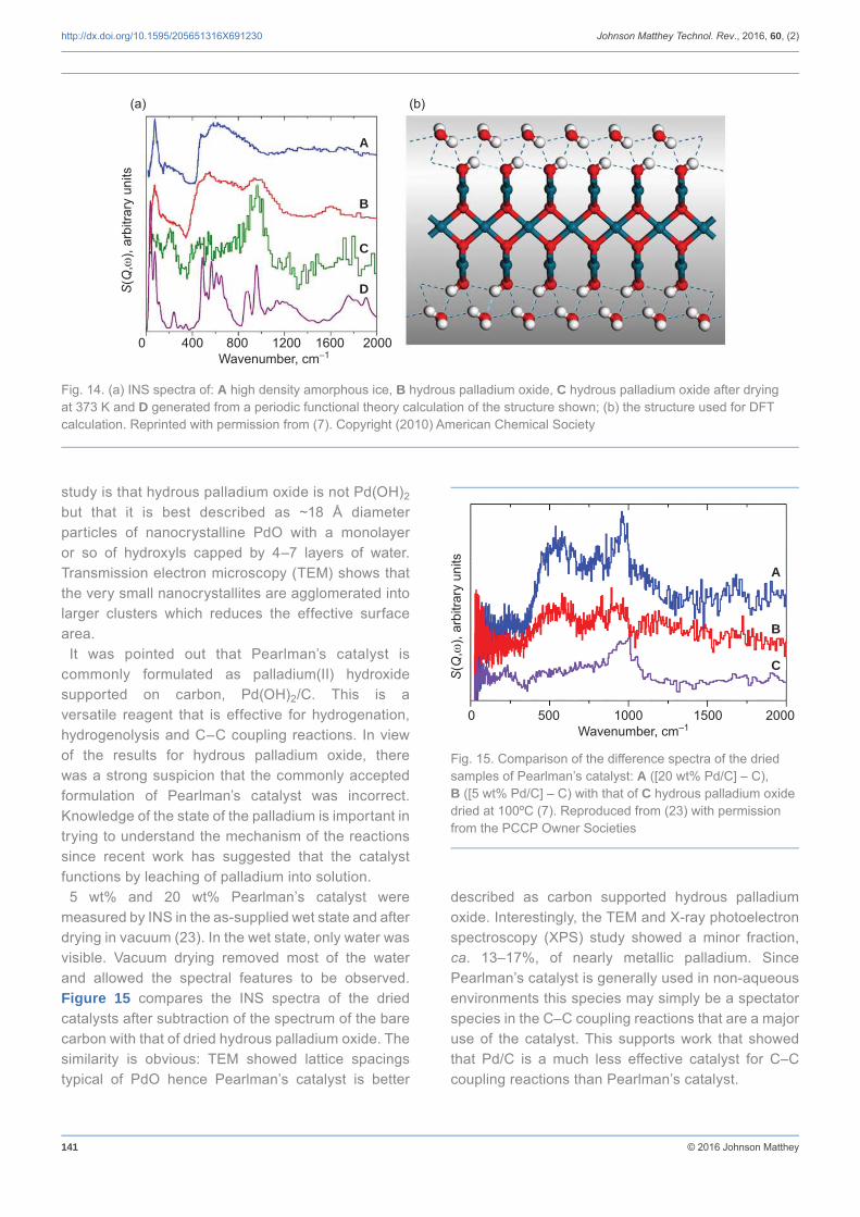
In Figure 4 it was shown that hydrous palladium oxide, PdO·H2O, has a core of nanocrystalline PdO. This leaves the role of water unresolved. Figure 14(a) compares the INS spectra of high density amorphous ice (Figure 14(a), line A) with PdO·H2O (Figure 14(a), line B) (7). The similarity of the spectra suggests that the water is present as a disordered shell on the PdO nanoparticle. However, there is an additional peak at ~1000 cm–1
that is more apparent after drying at 373 K under vacuum (Figure 14(a), line C). This is assigned to a Pd–O–H deformation mode (the corresponding O–H stretch can be seen with a different spectrometer) and indicates a layer of hydroxyls at the surface. This system was modelled with periodic density functional theory as a two layer slab of PdO capped with hydroxyls and a layer of water, Figure 14(b). It can be seen that the INS spectrum generated from this model (Figure 14(a), line D) shows reasonable agreement with the experimental data (Figure 14(a),line C), although it does not capture the disorder in the water layer. The structure that emerges from the combined diffraction, spectroscopy and modelling
Fig. 11. (a) INS spectra of an iron-based Fischer-Tropsch catalyst taken from an operating plant. The sample was Soxhlet extracted in toluene for 24 hours to remove hydrocarbon product; (b) same sample as (a) showing equal numbers of aliphatic and aromatic C–H bonds; (c) a model iron-based Fischer-Tropsch catalyst, A before and B after six hours methanation (21, 22). Reproduced from (20) and (21) with permission of Wiley-VCH Verlag GmbH & Co and the Institute of Physics, respectively
(a)
(b)
(c)
A
B
0 1000 2000 3000 4000Wavenumber, cm–1
2200 2600 3000 3400 3800Wavenumber, cm–1
2000 2500 3000 3500 4000Wavenumber, cm–1
S(Q
,),
arbi
trary
uni
tsS
(Q,
), ar
bitra
ry u
nits
S(Q
,),
arbi
trary
uni
ts
0.15
0.10
0.05
2942
3061

140 © 2016 Johnson Matthey
http://dx.doi.org/10.1595/205651316X691230 Johnson Matthey Technol. Rev., 2016, 60, (2)
Fig. 12. A photograph of the gas handling apparatus (blue panel), that is housed within a walk-in fume cupboard. The furnace is located to the left hand side of the gas panel and is mounted on a heavy-duty lab-jack. A cell is in the furnace, which is connected to the gas panel by heated lines that terminate in high-temperature valves, which may be used to isolate the cell. The reaction may be followed by online mass spectrometry using the Hiden RGA on the trolley at the left of the picture. Toxic gas (H2 or CO) monitors (black boxes on the walls on the extreme left and right of the picture) are integral to automatic safety shutdown safeguards. A more complete description is given elsewhere (21)
Fig.13. INS cell designed to carry out high-temperature and high-pressure (600ºC, 20 bar) reactions. The cell body is made of Inconel™. Similar designs are used for less severe operation: 316 stainless steel (300ºC, 5 bar), aluminium (100ºC, 1 bar) and TiZr (100ºC, 1 bar). The background scattering from the cell decreases in the order given. TiZr is not suitable for use with hydrogen due to rapid embrittlement above ~50ºC (21)
141 © 2016 Johnson Matthey
http://dx.doi.org/10.1595/205651316X691230 Johnson Matthey Technol. Rev., 2016, 60, (2)
study is that hydrous palladium oxide is not Pd(OH)2
but that it is best described as ~18 Å diameter particles of nanocrystalline PdO with a monolayer or so of hydroxyls capped by 4–7 layers of water. Transmission electron microscopy (TEM) shows that the very small nanocrystallites are agglomerated into larger clusters which reduces the effective surface area.
It was pointed out that Pearlman’s catalyst is commonly formulated as palladium(II) hydroxide supported on carbon, Pd(OH)2/C. This is a versatile reagent that is effective for hydrogenation, hydrogenolysis and C–C coupling reactions. In view of the results for hydrous palladium oxide, there was a strong suspicion that the commonly accepted formulation of Pearlman’s catalyst was incorrect. Knowledge of the state of the palladium is important in trying to understand the mechanism of the reactions since recent work has suggested that the catalyst functions by leaching of palladium into solution.
5 wt% and 20 wt% Pearlman’s catalyst were measured by INS in the as-supplied wet state and after drying in vacuum (23). In the wet state, only water was visible. Vacuum drying removed most of the water and allowed the spectral features to be observed. Figure 15 compares the INS spectra of the dried catalysts after subtraction of the spectrum of the bare carbon with that of dried hydrous palladium oxide. The similarity is obvious: TEM showed lattice spacings typical of PdO hence Pearlman’s catalyst is better
described as carbon supported hydrous palladium oxide. Interestingly, the TEM and X-ray photoelectron spectroscopy (XPS) study showed a minor fraction, ca. 13–17%, of nearly metallic palladium. Since Pearlman’s catalyst is generally used in non-aqueous environments this species may simply be a spectator species in the C–C coupling reactions that are a major use of the catalyst. This supports work that showed that Pd/C is a much less effective catalyst for C–C coupling reactions than Pearlman’s catalyst.
Fig. 14. (a) INS spectra of: A high density amorphous ice, B hydrous palladium oxide, C hydrous palladium oxide after drying at 373 K and D generated from a periodic functional theory calculation of the structure shown; (b) the structure used for DFT calculation. Reprinted with permission from (7). Copyright (2010) American Chemical Society
(a) (b)
A
B
C
D
0 400 800 1200 1600 2000Wavenumber, cm–1
S(Q
,),
arbi
trary
uni
ts
Fig. 15. Comparison of the difference spectra of the dried samples of Pearlman’s catalyst: A ([20 wt% Pd/C] – C), B ([5 wt% Pd/C] – C) with that of C hydrous palladium oxide dried at 100ºC (7). Reproduced from (23) with permission from the PCCP Owner Societies
0 500 1000 1500 2000Wavenumber, cm–1
S(Q
,),
arbi
trary
uni
ts
A
B
C

142 © 2016 Johnson Matthey
http://dx.doi.org/10.1595/205651316X691230 Johnson Matthey Technol. Rev., 2016, 60, (2)
Future Prospects
It will be obvious that most of this review concerns inelastic scattering. Partly this refl ects the bias and interests of the authors but it is also a refl ection of the current landscape. Inelastic scattering is more widely used even though it is less sensitive than elastic scattering. This arises because the energy analysis methods all involve rejecting most of the neutrons in either the incident or scattered beam. QENS studies are routinely carried out at varying temperatures to yield activation energies as well as diffusion constants and insight into the diffusion mechanism (Fickian, jump or immobile). To date most INS studies have used a ‘react and quench’ approach (14, 17–22) to provide a snapshot along the reaction coordinate. This is largely because of the need to measure spectra at
low temperature (<50 K) to obtain the best results. However, recent work (29) has shown that in favourable cases it is possible to obtain time resolved results at ambient temperature or above. The time resolution is very modest (10s of minutes) but this will improve as the instruments’ sensitivities improve.
Elastic scattering by contrast has been massively underused in studies of catalysts. The technique is well-suited to operando measurements: realistic temperatures and pressures are accessible, the penetrating nature of neutrons means that there is a wide choice of materials for cell design, time resolution of minutes or better is available and hydrogenous reactants and products give strong signals. An example where neutron diffraction studies are potentially very useful, would be to follow the evolution of an iron-based Fischer-Tropsch catalyst from the hematite pre-catalyst
How to Access Neutron Scattering Techniques
Neutron scattering facilities occur across the globe, Figure 16, (24) but the pre-eminent facilities are: ISIS in the UK (25), the Institut Laue Langevin (ILL) in France (26), the Spallation Neutron Source (SNS) in the USA (27) and J-PARC in Japan (28). All of these, and most of the smaller centres, operate a system of “free at the point at use”. Generally, beamtime is awarded via a competitive proposal system with application dates in the spring and autumn. If time is awarded, then the user is responsible for travel, subsistence and the preparation of samples but there is no charge for the actual beamtime. (Depending on the nationality of the user, the facility may partially or wholly cover these costs). This access mechanism requires that the work is made publicly available, generally by publication. The facilities also allow beamtime to be purchased and the work is then subject to a confi dentiality agreement.
A proposal generally consists of a two page science case plus experimental requirements and safety considerations. For new or inexperienced users, it is essential to discuss the proposal with an established user or the instrument scientist to avoid failure of the experiment. This is especially the case for catalysis experiments. The requirements include:• Suffi cient sample quantity (g not mg are generally
needed)• A large number of active sites (the minimum
for current inelastic instruments is 1 mol% of hydrogen in the beam)
• At least one of the surface species must be hydrogenous.
Even for experienced users, the fi rst experiment at the start of a new project is often unsuccessful. In this case, the problem may be that the physical characteristics are different on the gram scale (for example, different space velocities or plugging). However, the experienced user learns from the problem and subsequent experiments are generally successful.
Fig. 16. The location of neutron scattering centres in 2015, coloured by continent. Reproduced from (24) with permission of Neutronsources.org

143 © 2016 Johnson Matthey
http://dx.doi.org/10.1595/205651316X691230 Johnson Matthey Technol. Rev., 2016, 60, (2)
to the working catalyst which includes other iron oxides, iron carbides, metallic iron and carbon, under operando conditions. Neutrons are sensitive to the light elements as well as the heavy ones, Figure 1, so phase identifi cation should be more certain. Although it has not been discussed here, small angle neutron scattering (SANS) covers the size range typical of supported catalysts and the pores in microporous materials. Real time study of pore fi lling is clearly feasible.
Neutron scattering is a fl ux limited technique and there is a continual push to improve sensitivity by increasing the detector coverage, increasing the incident fl ux by better neutron transport from source to sample and by building more powerful facilities. The latest facilities, SNS (27) and J-PARC (28), are nearly a factor of 10 brighter than the previous generation. The European Spallation Source (ESS, (30)) under construction in Sweden will offer at least another factor of 10.
The other way that more information will be extracted from the data is via better modelling. Throughout this paper the link with atomistic modelling has been demonstrated; neutrons are particularly strong here because neutron observables are readily calculable as a result of the simple interaction between the neutron and the sample. Neutrons and modelling are a synergistic couple; the neutron data is an exacting test of the model and the modelling allows deeper insight into the process. QENS and MD simulations such as shown in Figure 8 are a good illustration of the synergy.
Conclusions
Neutron scattering is a very versatile tool that is underused for studies of catalysts. While it is applicable to most elements it has a particular focus on light elements, especially hydrogen. Thus it is highly complementary to synchrotron studies with X-rays that excel for the heavier elements. Neutron scattering provides observables that are readily calculable, thus modelling and neutron scattering are a natural partnership. This review has highlighted the detailed information that can be extracted from QENS and INS studies. Elastic neutron scattering has much to offer catalysis, particularly in the areas of operando studies of catalyst activation and deactivation, pore fi lling of micro- and mesoporous materials and the location of hydrogen or hydroxyls in materials. Neutrons are
a resource that are much simpler to access than is generally believed, new users with interesting problems are always welcome!
Acknowledgements The STFC Rutherford Appleton Laboratory is thanked for access to neutron beam facilities. The UK Catalysis Hub is kindly thanked for resources and support provided via our membership of the UK Catalysis Hub Consortium and funded by EPSRC (grants EP/K014706/1, EP/K014668/1, EP/K014854/1, EP/K014714/1 and EP/M013219/1).
References1. N. Floquet, J. P. Coulomb, J. P. Bellat, J. M. Simon,
G. Weber and G. Andre, J. Phys. Chem. C, 2007, 111, (49), 18182
2. M. Bianchini, F. Fauth, E. Suard, J.-B. Leriche, C. Masquelier and L. Croguennec, Acta Cryst. B, 2015, 71, 688
3. F. G. Kinyanjui, S. T. Norberg, I. Ahmed, S. G. Eriksson and S. Hull, Solid State Ionics, 2012, 225, 312
4. T. Kandemir, D. Wallacher, T. Hansen, K.-D. Liss, R. N. d’Alnoncourt, R. Schlögl and M. Behrens, Nucl. Instrum. Meth. A, 2012, 673, 51
5. T. Kandemir, F. Girgsdies, T. C. Hansen, K.-D. Liss, I. Kasatkin, E. L. Kunkes, G. Wowsnick, N. Jacobsen, R. Schlögl and M. Behrens, Angew. Chem. Int. Ed., 2013, 52, (19), 5166
6. T. Egami and S. J. L. Billinge, “Underneath the Bragg Peaks: Structural Analysis of Complex Materials”, 2nd edition, Pergamon Materials Series, Volume 16, Elsevier Ltd, Amsterdam, The Netherlands, 2012
7. S. F. Parker, K. Refson, A. C. Hannon, E. Barney, S. J. Robertson and P. Albers, J. Phys. Chem. C, 2010, 114, (33), 14164
8. J. F. C. Turner, C. J. Benmore, C. M. Barker, N. Kaltsoyannis, J. M. Thomas, W. I. F. David and C. R. A. Catlow, J. Phys. Chem. B, 2000, 104, (32), 7570
9. S. F. Parker, D. T. Bowron, S. Imberti, A. K. Soper, K. Refson, E. S. Lox, M. Lopez and P. Albers, Chem. Commun., 2010, 46, (17), 2959
10. M. Bée, “Quasielastic Neutron Scattering”, Adam Hilger, Bristol, UK, 1988
11. H. Jobic, Curr. Opin. Solid State Mater. Sci., 2002, 6, (5), 415
12. A. J. O’Malley and C. R. A. Catlow, Phys. Chem. Chem. Phys., 2015, 17, (3), 1943
13. A. J. O’Malley, C. R. A. Catlow, M. Monkenbusch

144 © 2016 Johnson Matthey
http://dx.doi.org/10.1595/205651316X691230 Johnson Matthey Technol. Rev., 2016, 60, (2)
and H. Jobic, J. Phys. Chem. C, 2015, 119, (48), 26999
14. A. J. O’Malley, S. F. Parker, A. Chutia, M. R. Farrow, I. P. Silverwood, V. García-Sakai and C. R. A. Catlow, Chem. Commun., 2016, 52, (14), 2897
15. P. C. H. Mitchell, S. F. Parker, A. J. Ramirez-Cuesta and J. Tomkinson, “Vibrational Spectroscopy with Neutrons: With Applications in Chemistry, Biology, Materials Science and Catalysis”, Series on Neutron Techniques and Applications, Volume 3, World Scientifi c, Singapore, 2005
16. S. F. Parker, D. Lennon and P. W. Albers, Appl. Spectrosc., 2011, 65, (12), 1325
17. I. P. Silverwood, N. G. Hamilton, C. J. Laycock, J. Z. Staniforth, R. M. Ormerod, C. D. Frost, S. F. Parker and D. Lennon, Phys. Chem. Chem. Phys., 2010, 12, (13), 3102
18. A. R. McFarlane, I. P. Silverwood, R. Warringham, E. L. Norris, R. M. Ormerod, C. D. Frost, S. F. Parker and D. Lennon, RSC Adv., 2013, 3, (37), 16577
19. A. R. McFarlane, I. P. Silverwood, E. L. Norris, R. M. Ormerod, C. D. Frost, S. F. Parker and D. Lennon, Chem. Phys., 2013, 427, 54
20. N. G. Hamilton, I. P. Silverwood, R. Warringham, J. Kapitán, L. Hecht, P. B. Webb, R. P. Tooze, S. F. Parker and D. Lennon, Angew. Chem. Int. Ed., 2013, 52, (21), 5608
21. R. Warringham, D. Bellaire, S. F. Parker, J. Taylor, R. A. Ewings, C. M. Goodway, M. Kibble, S. R. Wakefi eld, M. Jura, M. P. Dudman, R. P. Tooze, P. B. Webb and D. Lennon, J. Phys.: Conf. Ser., 2014, 554, 012005
22. R. Warringham, A. R. McFarlane, D. A. MacLaren, P. B. Webb, R. P. Tooze, J. Taylor, R. A. Ewings, S. F. Parker and D. Lennon, J. Chem. Phys., 2015, 143, 174703
23. P. W. Albers, K. Möbus, S. D. Wieland and S. F. Parker, Phys. Chem. Chem. Phys., 2015, 17, (7), 5274
24. Neutronsources.org, Neutron Centres: http://neutronsources.org/neutron-centres.html (Accessed on 17th February 2016)
25. ISIS, Science and Technology Facilities Council, Rutherford Appleton Laboratory, UK: http://www.isis.stfc.ac.uk (Accessed on 17th February 2016)
26. Institut Laue-Langevin, Grenoble, France: www.ill.eu (Accessed on 17th February 2016)
27. Oak Ridge National Laboratory, Spallation Neutron Source, US Department of Energy: http://neutrons.ornl.gov/sns (Accessed on 17th February 2016)
28. Japan Proton Accelerator Research Complex, Ibaraki, Japan: j-parc.jp/index-e.html (Accessed on 17th February 2016)
29. S. F. Parker, Chem. Commun., 2011, 47, (7), 1988
30. European Spallation Source, Tunavägen, Lund, Sweden: www.europeanspallationsource.se/ (Accessed on 17th February 2016)
The Authors
Stewart Parker is the ISIS Facility Catalysis Scientist. After earning his PhD at the University of California at Santa Barbara, USA, he carried out postdoctoral research at the University of East Anglia, UK, before joining the Analytical Division of the BP Research Centre at Sunbury-on-Thames, UK. In 1993 he moved to the ISIS Facility. He is currently responsible for promoting the use of neutrons in catalysis research. He interacts with a wide range of scientists from academia and industry studying areas that range from Fischer-Tropsch catalysis to methanol-to-hydrocarbons to selective hydrogenation catalysts using a variety of structural and spectroscopic neutron methods.
Paul Collier is a Research Fellow at the Johnson Matthey Technology Centre, Sonning Common, UK. He is responsible for organising Johnson Matthey’s collaborations at the Harwell site, 25 km from the Johnson Matthey Technology Centre, which hosts the world class facilities such as the UK’s synchrotron (Diamond) and the ISIS neutron spallation source. He is interested in heterogeneous and homogeneous catalysis, metal organic frameworks (MOFs), platinum group metals, oxidation, synchrotron, neutron diffraction, neutron spectoscopy, lasers, zeolite catalysts, methane and alkanes.