
JMA-5310-6 JMA-5320-7/9 JMA-5330-12 - EMForensics JMA-5300 Instruction.pdf · - i - PREFACE Thank...
440
MARINE RADAR EQUIPMENT INSTRUCTION MANUAL JMA-5310-6 JMA-5320-7/9 JMA-5330-12
Transcript of JMA-5310-6 JMA-5320-7/9 JMA-5330-12 - EMForensics JMA-5300 Instruction.pdf · - i - PREFACE Thank...
MARINE RADAREQUIPMENT
INSTRUCTIONMANUAL
JMA-5310-6JMA-5320-7/9JMA-5330-12
◆◆◆PRECAUTIONS BEFORE OPERATION◆◆◆
■Cautions for high voltage High voltages from hundreds volts to tens of thousands volts are to be applied to the electronic equipment such radio and radar devices. You do not face any danger during normal operation, but sufficient cares are required for maintenance, inspection and adjustment of their internal components. (Maintenance, check-up and adjustment of the inside of the equipment are prohibited except by maintenance specialists.) High voltages of tens of thousands volts are so dangerous as to bring an instantaneous death from electric shock, but even voltages of hundred volts may sometimes lead to a death from electric shock. To prevent such an accident, make it a rule to turn off the power switch, discharge capacitors with a wire surely earthed on an end make sure that internal parts are no longer charged before you touch any parts inside these devices. At the time, wearing dry cotton gloves ensures you further to prevent such danger. It is also a necessary caution to put one of your hands in the pocket and not to use your both hands at the same time. It is also important to select a stable foothold always to prevent additional injuries once you were shocked by electricity. If you were injured from electric shock, disinfect the burn sufficiently and get it taken care of promptly.
■What to do in case of electric shock When finding a victim of electric shock, turn off the power source and earth the circuit immediately. If it is impossible to turn off the circuit, move the victim away promptly using insulators such as dry wood plate and cloth without touching the victim directly. In case of electric shock, breathing may stop suddenly if current flows to the respiration center in the brain. If the shock is not so strong, artificial respiration may recover breathing. When shocked by electricity, the victim will come to look very bad with weak pulse or without beating, resulting in unconsciousness and rigidity.
- ii -
◆◆◆FIRST-AID TREATMENTS◆◆◆
☆First-aid treatments As far as the victim of electric shock is not in dangerous condition, do not move him and practice artificial respiration on him immediately. Once started, it should be continued rhythmically.
(1) Do not touch the victim confusedly as a result of the accident, but the rescuer may also get an
electric shock. (2) Turn off the power source calmly and move the victim away quietly from the electric line. (3) Call a physician or ambulance immediately or ask someone to call a doctor. (4) Lay the victim on this back and loosen his necktie, clothes, belt, etc. (5) a. Examine the victim’s pulse. b. Examine his heartbeat bringing your ear close to his heart. c. Examine his breathing bringing the back of your hand or your face close to his face. d. Check the size of the pupils of his eyes. (6) Open the victim’s mouth and take out artificial teeth, cigarette or chewing gum if any.
Keep his mouth open, stretch his tongue and insert a towel or the like in his mouth to prevent the tongue from suffocating. (If it is hard to open his mouth due to set teeth, open it with a screwdriver and insert a towel in this mouth.)
(7) Then, wipe his mouth so that foaming mucus does not accumulate inside.
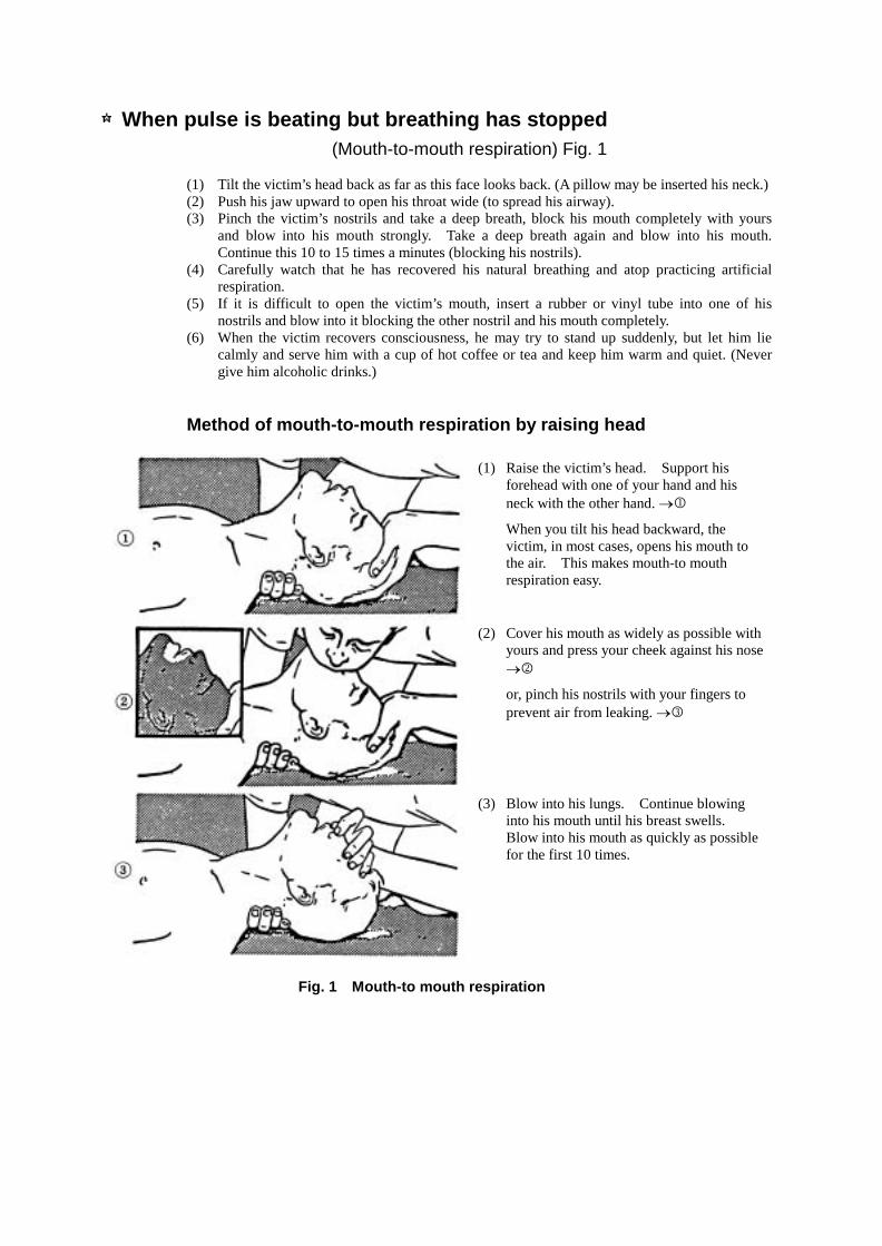
☆When pulse is beating but breathing has stopped (Mouth-to-mouth respiration) Fig. 1
(1) Tilt the victim’s head back as far as this face looks back. (A pillow may be inserted his neck.) (2) Push his jaw upward to open his throat wide (to spread his airway). (3) Pinch the victim’s nostrils and take a deep breath, block his mouth completely with yours
and blow into his mouth strongly. Take a deep breath again and blow into his mouth. Continue this 10 to 15 times a minutes (blocking his nostrils).
(4) Carefully watch that he has recovered his natural breathing and atop practicing artificial respiration.
(5) If it is difficult to open the victim’s mouth, insert a rubber or vinyl tube into one of his nostrils and blow into it blocking the other nostril and his mouth completely.
(6) When the victim recovers consciousness, he may try to stand up suddenly, but let him lie calmly and serve him with a cup of hot coffee or tea and keep him warm and quiet. (Never give him alcoholic drinks.)
Method of mouth-to-mouth respiration by raising head
(1) Raise the victim’s head. Support his forehead with one of your hand and his neck with the other hand. ��
When you tilt his head backward, the victim, in most cases, opens his mouth to the air. This makes mouth-to mouth respiration easy.
(2) Cover his mouth as widely as possible with yours and press your cheek against his nose ��
or, pinch his nostrils with your fingers to prevent air from leaking. ��
(3) Blow into his lungs. Continue blowing into his mouth until his breast swells. Blow into his mouth as quickly as possible for the first 10 times.
Fig. 1 Mouth-to mouth respiration
- iv -
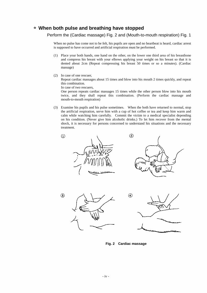
☆When both pulse and breathing have stopped Perform the (Cardiac massage) Fig. 2 and (Mouth-to-mouth respiration) Fig. 1
When no pulse has come not to be felt, his pupils are open and no heartbeat is heard, cardiac arrest is supposed to have occurred and artificial respiration must be performed. (1) Place your both hands, one hand on the other, on the lower one third area of his breastbone
and compress his breast with your elbows applying your weight on his breast so that it is dented about 2cm (Repeat compressing his breast 50 times or so a minutes). (Cardiac massage)
(2) In case of one rescuer, Repeat cardiac massages about 15 times and blow into his mouth 2 times quickly, and repeat
this combination. In case of two rescuers, One person repeats cardiac massages 15 times while the other person blow into his mouth
twice, and they shall repeat this combination. (Perform the cardiac massage and mouth-to-mouth respiration)
(3) Examine his pupils and his pulse sometimes. When the both have returned to normal, stop
the artificial respiration, serve him with a cup of hot coffee or tea and keep him warm and calm while watching him carefully. Commit the victim to a medical specialist depending on his condition. (Never give him alcoholic drinks.) To let him recover from the mental shock, it is necessary for persons concerned to understand his situations and the necessary treatment.
Fig. 2 Cardiac massage

- i -
PREFACE Thank you very much for purchasing the JRC marine radar equipment, JMA-5300 series. This equipment is a marine radar equipment designed to obtain safe operation of marine ships. This equipment consists of a radar signal transmitter-receiver unit, a LCD display unit and a scanner unit as its main units. � Before operating the equipment, be sure to read this instruction manual carefully for correct operation. � Maintain this instruction manual so that operators can refer to it at anytime. � Refer to this manual when any inconvenience or defect occurs.
- ii -
●Before Operation●
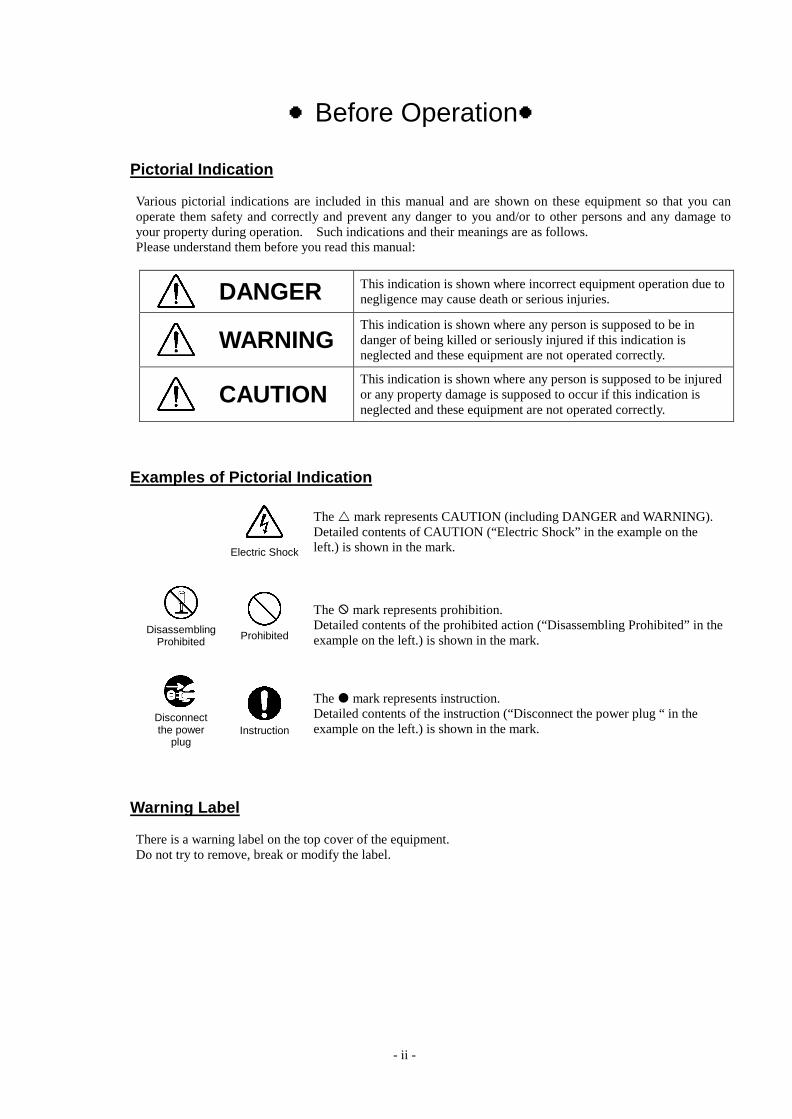
Pictorial Indication Various pictorial indications are included in this manual and are shown on these equipment so that you can operate them safety and correctly and prevent any danger to you and/or to other persons and any damage to your property during operation. Such indications and their meanings are as follows. Please understand them before you read this manual:
DANGER This indication is shown where incorrect equipment operation due to negligence may cause death or serious injuries.
WARNING This indication is shown where any person is supposed to be in danger of being killed or seriously injured if this indication is neglected and these equipment are not operated correctly.
CAUTION This indication is shown where any person is supposed to be injured or any property damage is supposed to occur if this indication is neglected and these equipment are not operated correctly.
Examples of Pictorial Indication
Electric Shock
The � mark represents CAUTION (including DANGER and WARNING). Detailed contents of CAUTION (“Electric Shock” in the example on the left.) is shown in the mark.
Disassembling
Prohibited
Prohibited
The � mark represents prohibition. Detailed contents of the prohibited action (“Disassembling Prohibited” in the example on the left.) is shown in the mark.
Disconnect the power
plug
Instruction
The � mark represents instruction. Detailed contents of the instruction (“Disconnect the power plug “ in the example on the left.) is shown in the mark.
Warning Label There is a warning label on the top cover of the equipment. Do not try to remove, break or modify the label.
- iii -
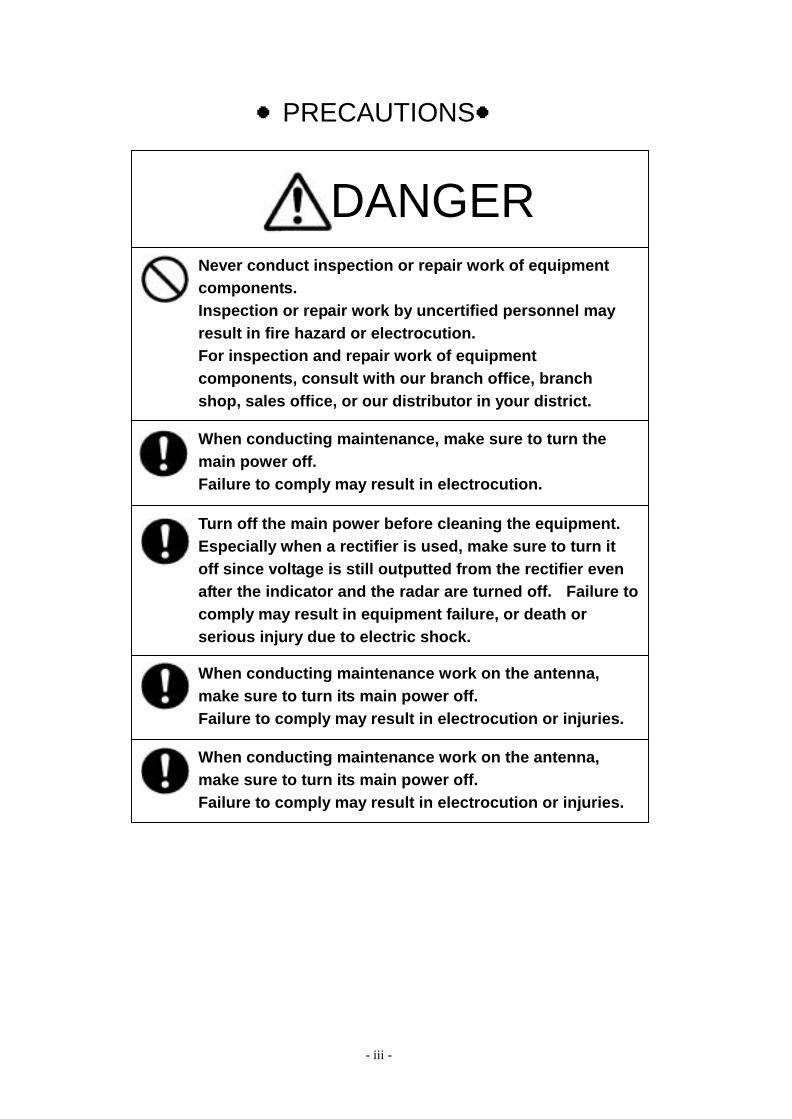
Never conduct inspection or repair work of equipment components. Inspection or repair work by uncertified personnel may result in fire hazard or electrocution. For inspection and repair work of equipment components, consult with our branch office, branch shop, sales office, or our distributor in your district.
When conducting maintenance, make sure to turn the main power off. Failure to comply may result in electrocution.
Turn off the main power before cleaning the equipment. Especially when a rectifier is used, make sure to turn it off since voltage is still outputted from the rectifier even after the indicator and the radar are turned off. Failure tocomply may result in equipment failure, or death or serious injury due to electric shock.
When conducting maintenance work on the antenna, make sure to turn its main power off. Failure to comply may result in electrocution or injuries.
When conducting maintenance work on the antenna, make sure to turn its main power off. Failure to comply may result in electrocution or injuries.
●PRECAUTIONS●
DANGER
- iv -
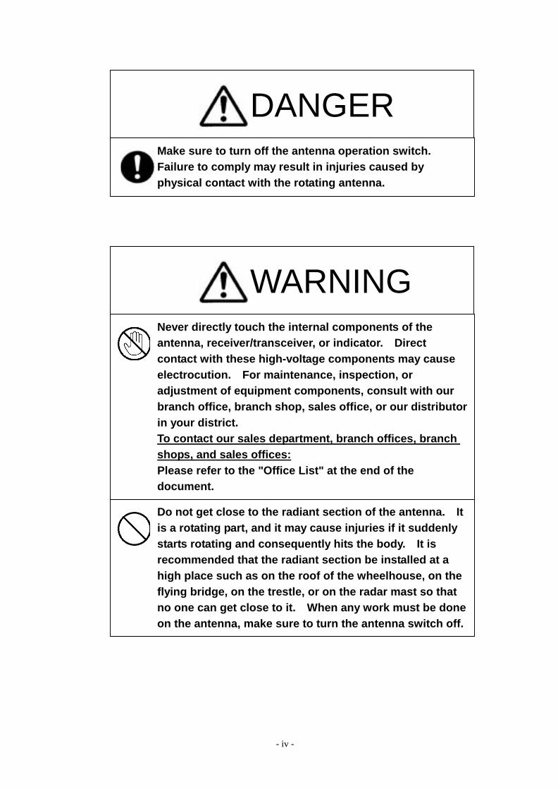
DANGER Make sure to turn off the antenna operation switch. Failure to comply may result in injuries caused by physical contact with the rotating antenna.
WARNING Never directly touch the internal components of the antenna, receiver/transceiver, or indicator. Direct contact with these high-voltage components may cause electrocution. For maintenance, inspection, or adjustment of equipment components, consult with our branch office, branch shop, sales office, or our distributorin your district. To contact our sales department, branch offices, branch shops, and sales offices: Please refer to the "Office List" at the end of the document.
Do not get close to the radiant section of the antenna. It is a rotating part, and it may cause injuries if it suddenly starts rotating and consequently hits the body. It is recommended that the radiant section be installed at a high place such as on the roof of the wheelhouse, on the flying bridge, on the trestle, or on the radar mast so that no one can get close to it. When any work must be done on the antenna, make sure to turn the antenna switch off.
- v -
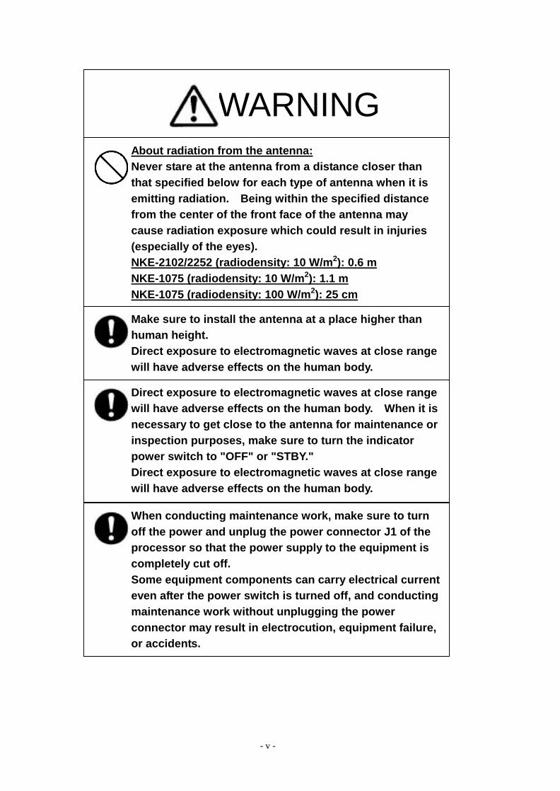
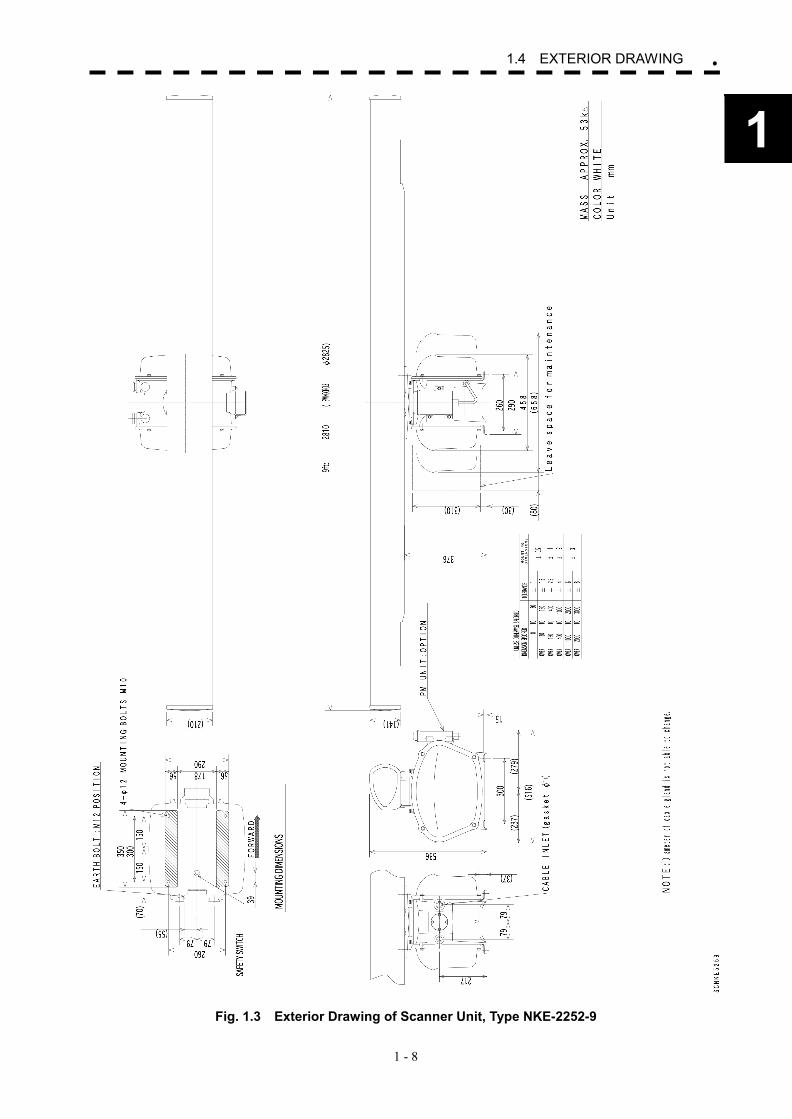
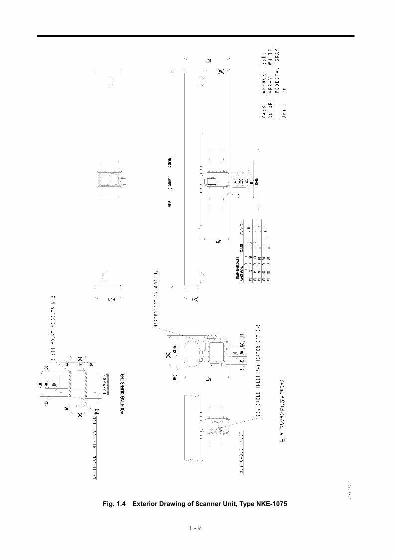
WARNING About radiation from the antenna: Never stare at the antenna from a distance closer than that specified below for each type of antenna when it is emitting radiation. Being within the specified distance from the center of the front face of the antenna may cause radiation exposure which could result in injuries (especially of the eyes). NKE-2102/2252 (radiodensity: 10 W/m2): 0.6 m NKE-1075 (radiodensity: 10 W/m2): 1.1 m NKE-1075 (radiodensity: 100 W/m2): 25 cm
Make sure to install the antenna at a place higher than human height. Direct exposure to electromagnetic waves at close range will have adverse effects on the human body.
Direct exposure to electromagnetic waves at close range will have adverse effects on the human body. When it is necessary to get close to the antenna for maintenance or inspection purposes, make sure to turn the indicator power switch to "OFF" or "STBY." Direct exposure to electromagnetic waves at close range will have adverse effects on the human body.
When conducting maintenance work, make sure to turn off the power and unplug the power connector J1 of the processor so that the power supply to the equipment is completely cut off. Some equipment components can carry electrical current even after the power switch is turned off, and conducting maintenance work without unplugging the power connector may result in electrocution, equipment failure, or accidents.
- vi -
CAUTION
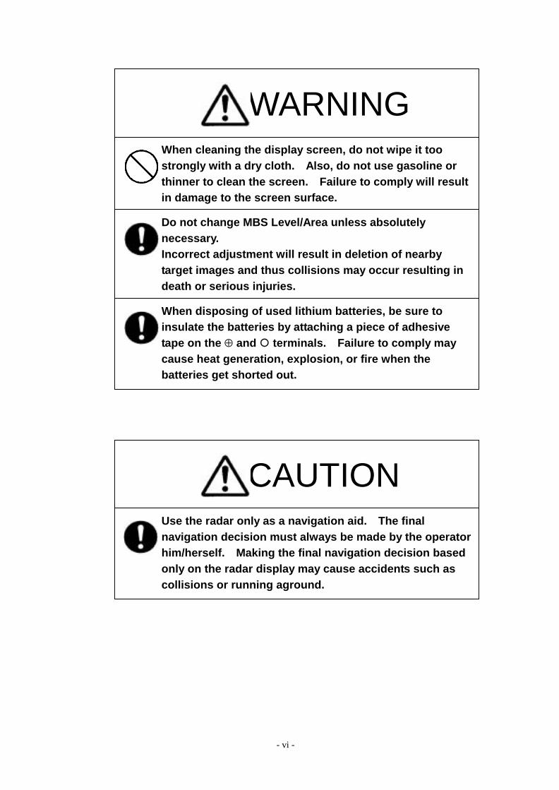
Use the radar only as a navigation aid. The final navigation decision must always be made by the operator him/herself. Making the final navigation decision based only on the radar display may cause accidents such as collisions or running aground.
WARNING When cleaning the display screen, do not wipe it too strongly with a dry cloth. Also, do not use gasoline or thinner to clean the screen. Failure to comply will result in damage to the screen surface.
When disposing of used lithium batteries, be sure to insulate the batteries by attaching a piece of adhesive tape on the � and � terminals. Failure to comply may cause heat generation, explosion, or fire when the batteries get shorted out.
Do not change MBS Level/Area unless absolutely necessary. Incorrect adjustment will result in deletion of nearby target images and thus collisions may occur resulting in death or serious injuries.
- vii -
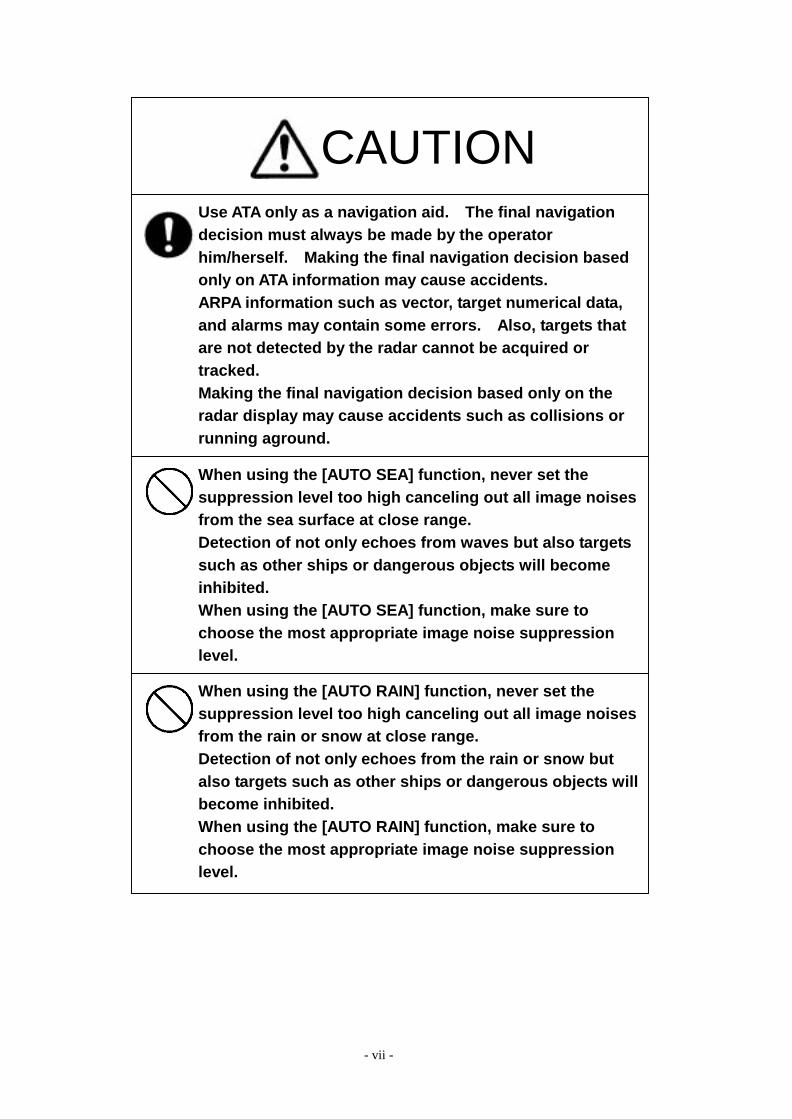
CAUTION Use ATA only as a navigation aid. The final navigation decision must always be made by the operator him/herself. Making the final navigation decision based only on ATA information may cause accidents. ARPA information such as vector, target numerical data, and alarms may contain some errors. Also, targets that are not detected by the radar cannot be acquired or tracked. Making the final navigation decision based only on the radar display may cause accidents such as collisions or running aground.
When using the [AUTO SEA] function, never set the suppression level too high canceling out all image noises from the sea surface at close range. Detection of not only echoes from waves but also targets such as other ships or dangerous objects will become inhibited. When using the [AUTO SEA] function, make sure to choose the most appropriate image noise suppression level.
When using the [AUTO RAIN] function, never set the suppression level too high canceling out all image noises from the rain or snow at close range. Detection of not only echoes from the rain or snow but also targets such as other ships or dangerous objects willbecome inhibited. When using the [AUTO RAIN] function, make sure to choose the most appropriate image noise suppression level.
- viii -
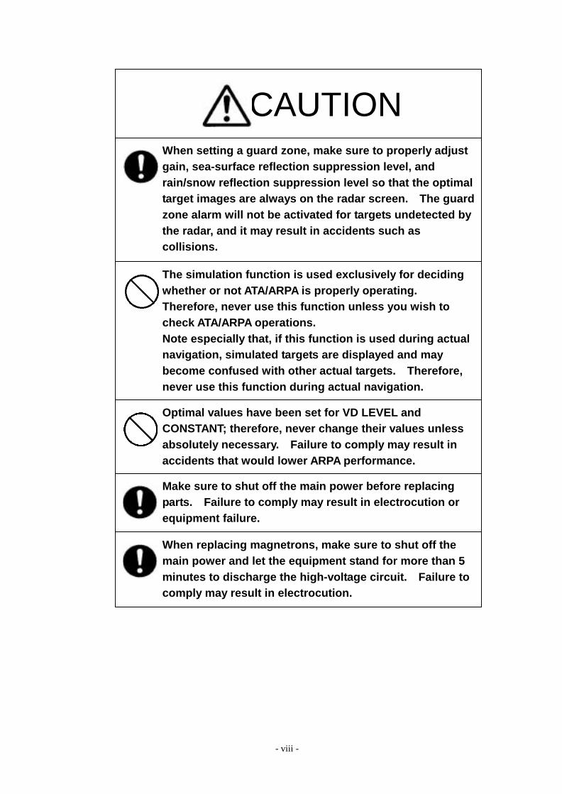
CAUTION When setting a guard zone, make sure to properly adjust gain, sea-surface reflection suppression level, and rain/snow reflection suppression level so that the optimal target images are always on the radar screen. The guardzone alarm will not be activated for targets undetected by the radar, and it may result in accidents such as collisions.
The simulation function is used exclusively for deciding whether or not ATA/ARPA is properly operating. Therefore, never use this function unless you wish to check ATA/ARPA operations. Note especially that, if this function is used during actual navigation, simulated targets are displayed and may become confused with other actual targets. Therefore, never use this function during actual navigation.
Optimal values have been set for VD LEVEL and CONSTANT; therefore, never change their values unless absolutely necessary. Failure to comply may result in accidents that would lower ARPA performance.
Make sure to shut off the main power before replacing parts. Failure to comply may result in electrocution or equipment failure.
When replacing magnetrons, make sure to shut off the main power and let the equipment stand for more than 5 minutes to discharge the high-voltage circuit. Failure to comply may result in electrocution.
- ix -
CAUTION Make sure to take off your watch when your hand must get close to the magnetron. Failure to comply may result in damage to the watch since the magnetron is a strong magnet.
Make sure that two or more staff member work together when replacing the LCD. If only one person attempts to replace the LCD, he/she may drop it and become injured.
Do not directly touch the inverter circuit of the LCD display with a bare hand since high voltage temporarily remains in the circuit even after the main power is shut off. Failure to comply may result in electrocution.
Any adjustments must be made by specialized service personnel. Incorrect settings may result in unstable operation.
Do not make any adjustments during navigation. Failure to comply may result in adverse effects on the radar function which may lead to accidents or equipment failure.
Any adjustments must be made by specialized service personnel. Failure to comply may result in accidents or equipment failure.
Do not make any adjustments during navigation. Failure to comply may result in adverse effects on the radar function which may lead to accidents or equipment failure.

- x -
CAUTION Do not change the quantization level settings unless absolutely necessary. If set at an inappropriate value, the acquisition or tracking function of ARPA deteriorates, and this may lead to accidents.
- xi -
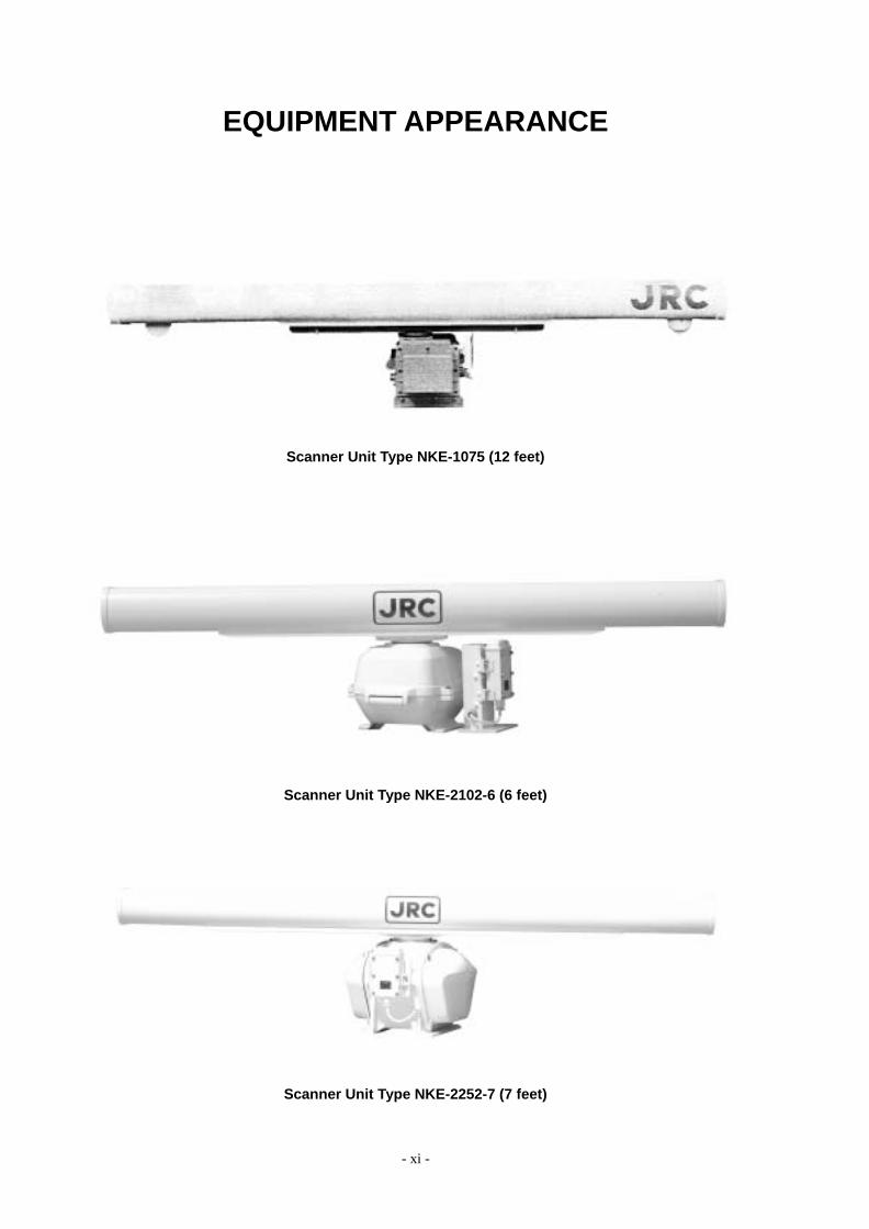
EQUIPMENT APPEARANCE
Scanner Unit Type NKE-1075 (12 feet)
Scanner Unit Type NKE-2102-6 (6 feet)
Scanner Unit Type NKE-2252-7 (7 feet)
- xii -
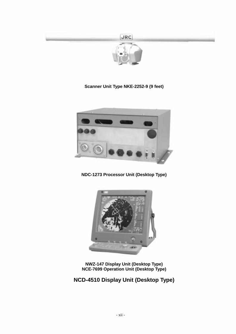
Scanner Unit Type NKE-2252-9 (9 feet)
NDC-1273 Processor Unit (Desktop Type)
NWZ-147 Display Unit (Desktop Type) NCE-7699 Operation Unit (Desktop Type)
NCD-4510 Display Unit (Desktop Type)
- xiii -
CONTENTS
PREFACE................................................................................................................i BEFORE OPERATION........................................................................................... ii PRECAUTIONS..................................................................................................... iii EQUIPMENT APPEARANCE ................................................................................ xi GLOSSARY.......................................................................................................... xx
1. GENERAL AND EQUIPMENT COMPOSITION
1.1 FUNCTIONS........................................................................................... 1-1 1.1.1 FUNCTION OF THIS SYSTEM ........................................................ 1-1
1.2 FEATURES............................................................................................. 1-2 1.3 CONFIGURATION.................................................................................. 1-4 1.4 EXTERIOR DRAWINGS......................................................................... 1-5 1.5 GENERAL SYSTEM DIAGRAMS......................................................... 1-14
2. NAMES AND FUNCTIONS OF CONTROL PANEL SWITCHES AND FUNCTIONS OF SOFTWARE BUTTONS
2.1 NAMES AND FUNCTIONS OF CONTROL PANEL SWITCHES ............ 2-1 2.2 FUNCTIONS OF SOFTWARE BUTTONS.............................................. 2-7
3. BASIC OPERATION
3.1 FLOW OPERATION................................................................................ 3-1 3.1.1 POWER ON AND START THE SYSTEM ......................................... 3-2 3.1.2 OBSERVE AND ADJUST VIDEO ..................................................... 3-3 3.1.3 ACQUIRE AND MEASURE DATA .................................................... 3-3 3.1.4 END THE OPERATION AND STOP THE SYSTEM ......................... 3-4
3.2 MENU COMPOSITION........................................................................... 3-5 3.2.1 OVERVIEW OF MENU STRUCTURE.............................................. 3-5 3.2.2 BASIC MENU OPERATION ............................................................. 3-6 3.3 PREPARATION ................................................................................ 3-8
- xiv -
3.3.1 ADJUST DISPLAY BRILLIANCE.......................................................3-8 3.3.2 ADJUST CONTRAST........................................................................3-8 3.3.3 ADJUST OPERATION PANEL BRILLIANCE [PANEL]......................3-9 3.3.4 SWITCH DAY/NIGHT MODE [DAY/NIGHT]......................................3-9 3.3.5 ADJUST BRILLIANCE OF INFORMATION ON RADAR DISPLAY
(BRILLIANCE SETTING) ................................................................3-10 3.3.6 ADJUST SOUND VOLUME (BUZZER VOLUME) .......................... 3-11 3.3.7 RESET ALARM BUZZER [ALARM ACK] ........................................ 3-11 3.3.8 SET DISPLAY COLOR....................................................................3-12
3.4 BASIC OPERATIONS ...........................................................................3-15 3.4.1 START TRANSMISSION [TX/PRF].................................................3-15 3.4.2 STOP TRANSMISSION [STBY] ......................................................3-15 3.4.3 CHANGE RANGE (OBSERVATION RANGE SCALE)
[RANGE+/-] .....................................................................................3-15 3.4.4 TUNE ..............................................................................................3-16 3.4.5 CONTROL SENSITIVITY [GAIN/PL]...............................................3-16 3.4.6 SUPPRESS SEA CLUTTER [AUTO-SEA] ......................................3-17 3.4.7 SUPPRESS RAIN/SNOW CLUTTER [AUTO-RAIN].......................3-19 3.4.8 REJECT RADAR INTERFERENCE [IR] .........................................3-21 3.4.9 HIDE/DISPLAY RANGE RINGS (RINGS) .......................................3-22 3.4.10 HIDE SHIP’S HEADING LINE (HL OFF).........................................3-22 3.4.11 HIDE GRAPHICS INFORMATION ON RADAR DISPLAY
(GRAPHIC DISPLAY)......................................................................3-23 3.5 GENERAL OPERATIONS .....................................................................3-24
3.5.1 MOVE CROSS CURSOR MARK BY TRACKBALL.........................3-24 3.5.2 USE EBLS (ELECTRONIC BEARING LINES) [EBL1/2] .................3-25 3.5.3 SET EBL OPERATION (EBL1 /2 SETTING) ...................................3-27 3.5.4 DISPLAY VARIABLE RANGE MARKERS [VRM1/VRM2]...............3-30 3.5.5 DISPLAY PARALLEL INDEX LINES (PARALLEL INDEX LINE) .....3-33 3.5.6 SWITCH BEARING DISPLAY MODE [AZI MODE] .........................3-41 3.5.7 SWITCH TRUE/RELATIVE MOTION DISPLAY MODE [TM/RM]....3-42 3.5.8 MOVE OWN SHIP’S DISPLAY POSITION [OFF CENT].................3-43 3.5.9 DISPLAY OTHER SHIPS’ TRAILS [TRAILS] ..................................3-44 3.5.10 SWITCH PULSE LENGTH (GAIN/PL) ............................................3-47 3.5.11 EXPAND TARGETS (TARGET ENHANCE) ....................................3-48 3.5.12 USE VIDEO PROCESS (PROCESS) .............................................3-49 3.5.13 ZOOM .............................................................................................3-50 3.5.14 USE MARKER [MOB] .....................................................................3-51 3.5.15 MARKING [MARK] ..........................................................................3-52 3.5.16 OPERATE EBL MANEUVER FUNCTION (EBL MANEUVER)........3-53
- xv -
3.5.17 OPERATE MULTI-FUNCTION CONTROL [MULTI]........................ 3-56 3.5.18 OPERATE USER KEY SWITCHES [USER KEY 1/2]..................... 3-58 3.5.19 OPERATION OF GUARD ZONE [ATA GUARD ZONE].................. 3-60 3.5.20 RADAR ALARM (RADAR ALARM)................................................. 3-63
3.6 DISPLAY OWN SHIP’S TRACK............................................................ 3-67 3.6.1 DISPLAY OWN SHIP’S TRACK (DISPLAY OWN TRACK) ............ 3-67 3.6.2 SET OWN SHIP’S TRACK DATA STORAGE INTERVAL
(OWN TRACK INTERVAL) ............................................................. 3-68 3.6.3 CLEAR OWN SHIP’S TRACK DATA (CLEAR OWN TRACK) ........ 3-69 3.6.4 CANCEL STORING OF OWN SHIP’S TRACK DATA
(OWN TRACK MEMORY) .............................................................. 3-70 3.7 DISPLAY CHARTS ............................................................................... 3-71
3.7.1 DISPLAY COASTLINE ROM CARD PRODUCED BY JRC............ 3-71 3.7.2 DISPLAY ERC CARD..................................................................... 3-72 3.7.3 FILL CHARTS (FILL LAND AREA) ................................................. 3-73
3.8 DISPLAY NAVIGATION INFORMATION............................................... 3-74 3.8.1 DISPLAY WAYPOINT MARKS (WAYPOINT DISPLAY).................. 3-74 3.8.2 DISPLAY NAVIGATION INFORMATION (NAV DISPLAY SETTING)3-75 3.8.3 CREATE/EDIT NAVIGATION INFORMATION (EDIT USER MAP). 3-76 3.8.4 SET NAVIGATION INFORMATION (USER MAP SETTING).......... 3-82 3.8.5 SET AND DISPLAY GEODETIC SYSTEM ..................................... 3-89
3.9 OPERATE PERFORMANCE MONITOR (PM DISPLAY)...................... 3-91 3.9.1 OPERATION PROCEDURES ........................................................ 3-91
3.10 APPLIED OPERATIONS ...................................................................... 3-97 3.10.1 SET RADAR SIGNAL PROCESSING (PROCESS SETTING)....... 3-97 3.10.2 SET RADAR TRAILS (RADAR TRAILS SETTING)...................... 3-100 3.10.3 SET CURSOR (CURSOR SETTING)........................................... 3-102 3.10.4 SET SCREEN............................................................................... 3-103 3.10.5 SET SCANNER (TRX SETTING) ................................................. 3-107 3.10.6 SET CHART DISPLAY (MAP SETTING) ...................................... 3-109 3.10.7 SET LORAN C (LORAN C CORRECTION) ..................................3-119
3.11 USE FUNCTION SWITCH [FUNC]..................................................... 3-120 3.11.1 OPERATION PROCEDURES ...................................................... 3-120 3.11.2 FUNCTION SETTING MENU ITEMS ........................................... 3-121 3.11.3 OVERVIEW OF FUNCTION OPERATIONS................................. 3-122 3.11.4 OVERVIEW OF STORED FUNCTION SETTING DATA............... 3-125 3.11.5 PERSONAL INFORMATION (PIN SETTING)............................... 3-126
3.12 USING CARD ..................................................................................... 3-129 3.12.1 SAVE IN AND TRANSFER TO CARD (MEM CAPA/COPY)......... 3-129 3.12.2 ERASE/INITIALIZE CARD MEMORY (CLR MEM INIT CARD) .... 3-133
- xvi -
4. MEASUREMENT OF RANGE AND BEARING
4.1 MEASUREMENT BY TRACKBALL .........................................................4-1 4.2 MEASUREMENT BY RANGE RINGS.....................................................4-2 4.3 MEASUREMENT BY EBLS AND VRMS.................................................4-3 4.4 MEASUREMENT BETWEEN TWO OPTIONAL POINTS .......................4-5
5. HOW TO USE ATA/ARPA
5.1 PREPARATION .......................................................................................5-2 5.1.1 COLLISION AVOIDANCE .................................................................5-3 5.1.2 DEFINITIONS OF SYMBOLS ...........................................................5-6 5.1.3 SETTING COLLISION DECISION CRITERIA (CPA/TCPA LIMIT) ....5-8 5.1.4 SETTING VECTORS (VECTOR TIME).............................................5-9 5.1.5 SETTING CPA RING (CPA RING)...................................................5-10 5.1.6 SETTING AUTOMATIC ACQUISITION KEY ASSIGNMENT
(GZ ALARM KEY SETTING) ........................................................... 5-11 5.2 EPA OPERATION..................................................................................5-12
5.2.1 PLOTTING TARGETS.....................................................................5-12 5.2.2 MODIFYING PLOTTED TARGET DATA .........................................5-13 5.2.3 CANCELING PLOTTED TARGET DATA.........................................5-13 5.2.4 DISPLAYING NUMERIC DATA OF PLOTTED TARGETS ..............5-14 5.2.5 SETTING EPA ALARM (AUDIBLE WARNING) ...............................5-15
5.3 ATA/ARPA OPERATION........................................................................5-16 5.3.1 ACQUIRING TARGET.....................................................................5-16 5.3.2 CANCELING UNWANTED TARGETS ............................................5-18 5.3.3 DISPLAYING TARGET ID NO. (TARGET NUMBER DISPLAY) ......5-19 5.3.4 ATA/ARPA DATA DISPLAY..............................................................5-20 5.3.5 TARGET DATA DISPLAY ................................................................5-25 5.3.6 ALARM DISPLAY............................................................................5-29 5.3.7 TRIAL MANEUVERING (TRIAL).....................................................5-33 5.3.8 ATA/ARPA SIMULATION.................................................................5-37 5.3.9 SETTING ATA/ARPA TRACKS (ATA TRACK SETTING) ................5-43
5.4 AIS OPERATION...................................................................................5-50 5.4.1 INITIAL SETTING............................................................................5-51 5.4.2 SETTING AIS DISPLAY FUNCTION (AIS FUNCTION) ..................5-53 5.4.3 ACTIVATING AIS TARGETS...........................................................5-54 5.4.4 DEACTIVATING AIS TARGETS ......................................................5-55
- xvii -
5.4.5 SETTING AIS SYMBOL DISPLAY FUNCTION (AIS SYMBOL DISPLAY)................................................................ 5-56
5.4.6 DISPLAYING NUMERIC DATA OF AIS TARGETS......................... 5-57 5.4.7 SETTING ATA/ARPA SYMBOL DISPLAY FUNCTION
(ATA SYMBOL DISPLAY) ............................................................... 5-59 5.4.8 SETTING AIS FILTER (AIS FILTER SETTING).............................. 5-60 5.4.9 DECIDING AIS TARGET AND ARPA TARGET AS THE
SAME ONE (IDENTICAL DISTANCE)............................................ 5-63 5.4.10 CONDITIONS FOR DECIDING AIS TARGET TO BE LOST .......... 5-65 5.4.11 DISPLAYING AIS SYMBOLS ......................................................... 5-66 5.4.12 AIS ALARM DISPLAY..................................................................... 5-67 5.4.13 RESTRICTIONS............................................................................. 5-68
6. TRUE AND FALSE ECHOES ON DISPLAY
6.1 RADAR WAVE WITH THE HORIZON .................................................... 6-2 6.2 STRENGTH OF REFLECTION FROM THE TARGET............................ 6-4 6.3 SEA CLUTTERS..................................................................................... 6-5 6.4 FALSE ECHOES .................................................................................... 6-6 6.5 DISPLAY OF RADAR TRANSPONDER (SART) .................................... 6-9
7. MAINTEMANCE 7.1 ROUTINE MAINTENANCE..................................................................... 7-1 7.2 MAINTENANCE ON EACH UNIT ........................................................... 7-2
8. TROUBLE SHOOTING AND ADJUSTMENT
8.1 PERFORMANCE CHECK ...................................................................... 8-1 8.2 FAULT FINDING ................................................................................... 8-21 8.3 TROUBLE SHOOTING......................................................................... 8-22 8.4 REPLACEMENT OF MAJOR PARTS................................................... 8-27 8.5 ADJUSTMENTS ................................................................................... 8-30 8.6 SETTING .............................................................................................. 8-62
9. AFTER-SALES SERVICE
10. DISPOSAL
- xviii -
10.1 DISPOSAL OF THE UNIT .....................................................................10-1 10.2 DISPOSAL OF USED BATTERIES.......................................................10-2 10.3 DISPOSAL OF USED MAGNETRON ...................................................10-3
11. SPECIFICATIONS
11.1 JMA-5310-6 TYPE RADAR................................................................... 11-1 11.2 JMA-5320-7/9 TYPE RADAR................................................................ 11-2 11.3 JMA-5330-12 TYPE RADAR................................................................. 11-3 11.4 SCANNER (NKE-2102)......................................................................... 11-4 11.5 SCANNER (NKE-2252)......................................................................... 11-5 11.6 SCANNER (NKE-1075)......................................................................... 11-6 11.7 DISPLAY UNIT(NCD-4510)................................................................... 11-7 11.8 PROCESSOR UNIT(NDC-1273)........................................................... 11-8 11.9 PLOTTER UNIT .................................................................................. 11-10 11.10 ARPA-1 (HIGH PERFORMANCE ARPA) ............................................ 11-12 11.11 ARPA-2 (NORMAL EDITION ATA) ...................................................... 11-13 11.12 KEYBOARD UNIT ............................................................................... 11-14 11.13 INPUT ENABLE SIGNAL .................................................................... 11-15 11.14 OUTPUT ENABLE SIGNAL ................................................................ 11-16 11.15 STANDARD CONFIGURATION .......................................................... 11-17 11.16 EQUIPMENT DISTANCE BETWEEN INSTRUMENTS....................... 11-18 11.17 OTHERS (OPTION) ............................................................................ 11-19
APPENDIX
ATTACHED DRAWING 1 CIRCUIT DIAGRAM OF RADAR, TYPE JMA-5310-6/5320-7/9
ATTACHED DRAWING 2 CIRCUIT DIAGRAM OF RADAR, TYPE JMA-5330-12 ATTACHED DRAWING 3 INTER-BOARD CONNECTION DIAGRAM OF RADAR,
TYPE JMA-5310-6 ATTACHED DRAWING 4 INTER-BOARD CONNECTION DIAGRAM OF RADAR,
TYPE JMA-5320-7/9 ATTACHED DRAWING 5 INTER-BOARD CONNECTION DIAGRAM OF RADAR,
TYPE JMA5330-12 ATTACHED DRAWING 6 POWER SYSTEM DIAGRAM OF RADAR, TYPE
JMA-5310-6 ATTACHED DRAWING 7 POWER SYSTEM DIAGRAM OF RADAR, TYPE
JMA-5320-7/9 ATTACHED DRAWING 8 POWER SYSTEM DIAGRAM OF RADAR, TYPE
JMA-5330-12

- xix -
ATTACHED DRAWING 9 INTERNAL CONNECTION DIAGRAM OF DISPLAY UNIT, TYPE NCD-4510
ATTACHED DRAWING 10 INTERNAL CONNECTION DIAGRAM OF PROCESSOR UNIT, TYPE NCD-1273
ATTACHED DRAWING 11 INTERNAL CONNECTION DIAGRAM OF OPERATION UNIT, TYPE NCE-7699
ATTACHED DRAWING 12 INTERNAL CONNECTION DIAGRAM OF CONNECTION UNIT, TYPE NQE-3151
- xx -
GLOSSARY
This section describes the main terms used for this equipment and general related maritime terms.
ARPA: Automatic Radar Plotting Aid.
AZI MODE (Azimuth Stabilization MODE): Bearing display mode
Anti-clutter rain (FTC): Rain/snow clutter suppression
Anti-clutter sea (STC): Sea clutter suppression
ATA (Automatic tracking Aid) Automatic tracking equipment
BCR (Bow Cross Range): Bow crossing range
BCT (Bow Cross Time): Bow crossing time
BRG (Bearing): Bearing
CPA (Closest Point of Approach): The closest point of approach from own ship, which can be set by the observer.
COG (Course Over Ground): Course relative to the ground.
CUP (Course-Up): Own ship’s course is pointed to the top center of the radar display.
DRIFT: The current velocity for manual correction or the current speed on the horizontal axis of the 2-axis log is displayed.
EBL (Electronic Bearing Line): An electronic bearing line originated from own ship’s position.
ENH (Enhance): A target can be enlarged.
Floating EBL (Floating Electronic Bearing Line): Floating electronic bearing line originated from an arbitrary point.
GND: Stabilization relative to the ground.
GPS (Global Positioning System): The position of a GPS receiver can be determined by the signals from GPS satellites.
Guard Zone: Alarm ring against intrusion
HDG (Heading): Own ship’s heading bearing. The display ranges from 000 to 360 degrees
as scanned clockwise. HL (Heading Line):
Ship’s heading line HUP (Head-Up):
Own ship’s heading line is always pointed to the top center of the radar display.
IMO: International Maritime Organization
Interswitch: A device to switch over two or more radar display units and two or more antennas.
IR (Interference Reflector): Radar interference reflector
MRK (Mark): Reflection plot
NM (Nautical Mile): 1NM=1852m
NSK (North Stabilization Kit): True bearing unit
NUP (North-Up): The north is always pointed to the top center of the radar display.
OWN TRACK: Display function of own ship’s track
PI (Parallel Index Line): Parallel index line
PIN (Personal Access Code): Information set by the user (personal code)
PM (Performance Monitor): An additional unit to monitor the transmitted power and the receiving sensitivity of radar equipment.
PROC (Process): Target processing function
PPI: Plan Position Indicator
Relative Vector: A target’s movement predicted relative to own ship.
RR (Range Rings): Fixed range ring
RM (Relative Motion): Relative motion presentation Own ship’s position is fixed and other targets move relative to own ship.
S/X Band: Radio frequency bands S: 3GHz band, X: 9 GHz band
- xxi -
SCANNER: Antenna
SEA:
Sea clutter suppression SET:
The current direction for manual correction or the current speed on the horizontal axis of the 2-axis log is displayed.
SOG (Speed Over Ground): Speed relative to the ground.
STAB (Stabilization): Stabilization
TCPA (Time to Closest Point of Approach): The time to approach the closest point from own ship.
TM (True Motion): True motion presentation A presentation in which own ship and any other target move depending on their individual movements.
TRAILS: Function of displaying tracks of other ships.
TRAIL: Trial maneuvering
True Vector: A target’s true movement predicted as the result of entering own ship’s direction and speed.
VRM (Variable Range Marker): Variable range marker
WATER: Stabilization relative to the water
xxii
3 4 5
2 1
6 7 8 9 1011
APPE
NDIX
APPE
NDIX
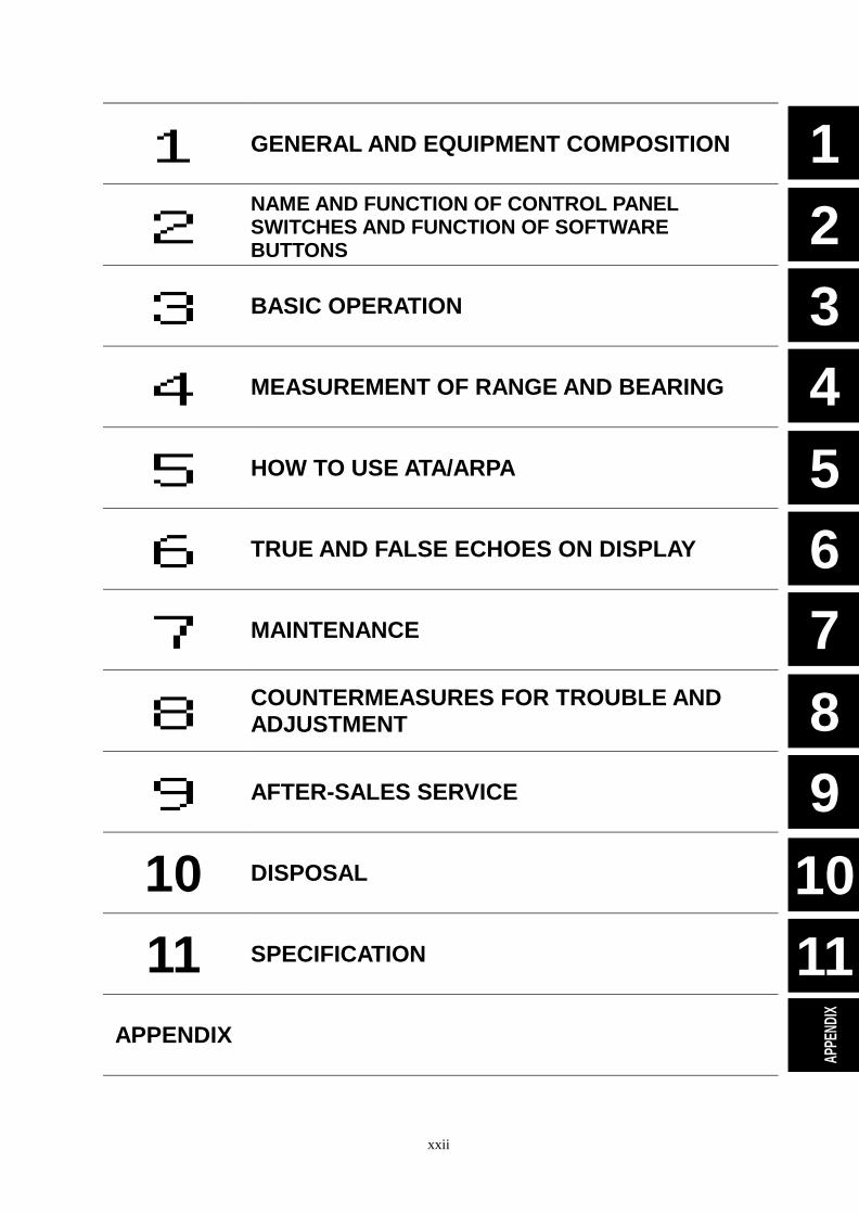
1 GENERAL AND EQUIPMENT COMPOSITION
2 NAME AND FUNCTION OF CONTROL PANEL SWITCHES AND FUNCTION OF SOFTWARE BUTTONS
3 BASIC OPERATION
4 MEASUREMENT OF RANGE AND BEARING
5 HOW TO USE ATA/ARPA
6 TRUE AND FALSE ECHOES ON DISPLAY
7 MAINTENANCE
8 COUNTERMEASURES FOR TROUBLE AND ADJUSTMENT
9 AFTER-SALES SERVICE
10 DISPOSAL
11 SPECIFICATION
APPENDIX
SECTION 1 GENERAL AND EQUIPMENT
COMPOSITION
1.1 Functions ......................................... 1
1.1.1 Function of This System ......... 1 1.2 Features ........................................... 2 1.3 Configuration................................... 4 1.4 Exterior Drawings............................ 5 1.5 General System Diagrams............ 14
1 - 1
1.1 FUNCTIONS
This equipment is a high-performance radar equipment consisting of a scanner unit, a transmitter-receiver unit and a high resolution color LCD display unit.
1.1.1 Function of This System
The JMA-5300 series is a color radar system designed to comply with the international standards of the IMO. The main functions include: �� sensitivity adjustment �� sea clutter and rain/snow clutter suppression �� interference reflector �� bearing and range measurement using a cursor, fixed/variable range markers, and electronic bearing
line �� own track display �� NAV line and marker displays �� TM (True Motion) presentation �� self-diagnostic facilities �� radar performance monitoring (Performance Monitor) �� ARPA functions (manual/automatic, target acquisition and tracking, vector and trail displays and alarm
displays) (option) �� simple plotter functions (marker and line display, destination/route setting) (option) �� 4-unit switchover (Inter switch) function (option)
1 - 2
11.2 FEATURES
Realization of Large, Easy-to-see Screen with High Resolution The 18.1-inch color LCD with high resolution of 1280 � 1024 pixels can display radar images of 250 mm or more in diameter. Even short-range targets can also be displayed as high-resolution images.
Target Detection by Latest Signal Processing Technology
The system employs the latest digital signal processing technology to eliminate undesired clutter from the radar video signals that are obtained from the receiver with a wide dynamic range, thus improving the target detection.
Advanced Technology Based ARPA/ATA Functions (Option) The ARPA target acquisition and tracking performance is enhanced by the use of the fastest DSP and tracking algorithm. So stable operation in target tracking under clutter is ensured. �� Acquisition and tracking of 100 targets for ARPA, 30 targets for ATA. �� Hazardous conditions are represented by shapes and colors of symbols as well as sounds. �� Trial maneuvering functions provided. (ARPA) �� Trails of up to 20 target ships can be stored with a maximum of 1,500 points for each of them, and displayed
distinguished by using seven different colors.
Overlay of Radar Images, Coastlines, and Own Ship's Track As well as operator-created NAV lines, the data of coastlines, objects such as buoys, and own ship's tracks/ARPA trails, which is stored on the memory card can be superimpose-displayed with radar images and radar trails in all display modes including the head-up mode. Use of the optional plotter function enables the creation/display of marks and lines and the settings of waypoints/courses.
Easy Operation with GUI All the radar functions can be easily controlled by simply using the trackball and two switches to operate the buttons shown on the radar display.
1 - 3
Improved Day/Night Mode Two types of background colors are available in each Day/Night mode (total 4 background colors). Each background color can be reproduced to be suited for the user’s operating environment by simple key operation. The radar echoes and a variety of graphics can also be represented in different colors, ensuring easy-to-see displays.
Compact Design and Low Power Consumption Since an LCD has been implemented as the display device, the weight of the display is greatly reduced and the power consumption is lowered in comparison with the conventional radar equipment.
Self-diagnostic Program Incorporated The Self-diagnostic program always monitors all the functions of the system. If any function deteriorates, an alarm message will appear on the radar display and an alarm sounds at the same time. Even when the system is operating, the functionality test can be carried out. (except on some functions)
Performance Monitor (Option) The radar performance (transmitted output power and receiving sensitivity) can appear on the radar display. * The PM unit (NJU-63/64) is needed separately.
Easy Interswitch Operation (Option) If an interswitch unit (option) is connected, up to four JMA-5300 radars can be switched over by performing simple operation. * An interswitch (NQA-3141-4) is needed separately.
Various Functions
�� TRAILS (Other ship’s) track display �� TM (True Motion display) �� Head-up/North-up/Course-up display �� Own ship’s track display �� Guard Zone function
1 - 4
11.3 CONFIGURATION
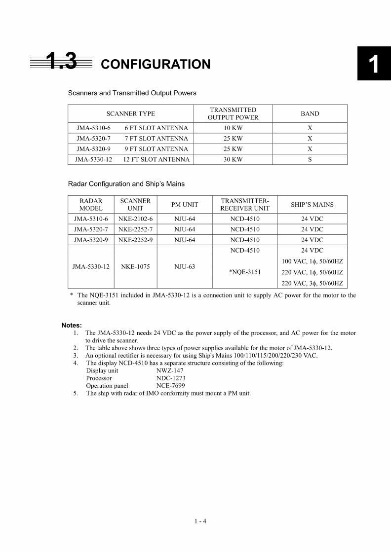
Scanners and Transmitted Output Powers
SCANNER TYPE TRANSMITTED OUTPUT POWER BAND
JMA-5310-6 6 FT SLOT ANTENNA 10 KW X JMA-5320-7 7 FT SLOT ANTENNA 25 KW X JMA-5320-9 9 FT SLOT ANTENNA 25 KW X
JMA-5330-12 12 FT SLOT ANTENNA 30 KW S
Radar Configuration and Ship’s Mains
RADAR MODEL
SCANNER UNIT PM UNIT TRANSMITTER-
RECEIVER UNIT SHIP’S MAINS
JMA-5310-6 NKE-2102-6 NJU-64 NCD-4510 24 VDC JMA-5320-7 NKE-2252-7 NJU-64 NCD-4510 24 VDC JMA-5320-9 NKE-2252-9 NJU-64 NCD-4510 24 VDC
NCD-4510 24 VDC
100 VAC, 1�, 50/60HZ
220 VAC, 1�, 50/60HZJMA-5330-12 NKE-1075 NJU-63
*NQE-3151
220 VAC, 3�, 50/60HZ
* The NQE-3151 included in JMA-5330-12 is a connection unit to supply AC power for the motor to the scanner unit.
Notes: 1. The JMA-5330-12 needs 24 VDC as the power supply of the processor, and AC power for the motor
to drive the scanner. 2. The table above shows three types of power supplies available for the motor of JMA-5330-12. 3. An optional rectifier is necessary for using Ship's Mains 100/110/115/200/220/230 VAC. 4. The display NCD-4510 has a separate structure consisting of the following:
Display unit NWZ-147 Processor NDC-1273 Operation panel NCE-7699
5. The ship with radar of IMO conformity must mount a PM unit.
1 - 5
1.4 EXTERIOR DRAWINGS Fig. 1.1 Exterior Drawing of Scanner Unit, Type NKE-2102-6 Fig. 1.2 Exterior Drawing of Scanner Unit, Type NKE-2252-7 Fig. 1.3 Exterior Drawing of Scanner Unit, Type NKE-2252-9 Fig. 1.4 Exterior Drawing of Scanner Unit, Type NKE-1075 Fig. 1.5 Exterior Drawing of Display Unit, Type NWZ-147 Fig. 1.6 Exterior Drawing of Processing Unit, Type NDC-1273 Fig. 1.7 Exterior Drawing of Operating Unit, Type NCE-7699 Fig. 1.8 Exterior Drawing of Connecting Unit, Type NQE-3151
1 - 6
1.4 EXTERIOR DRAWING�
1
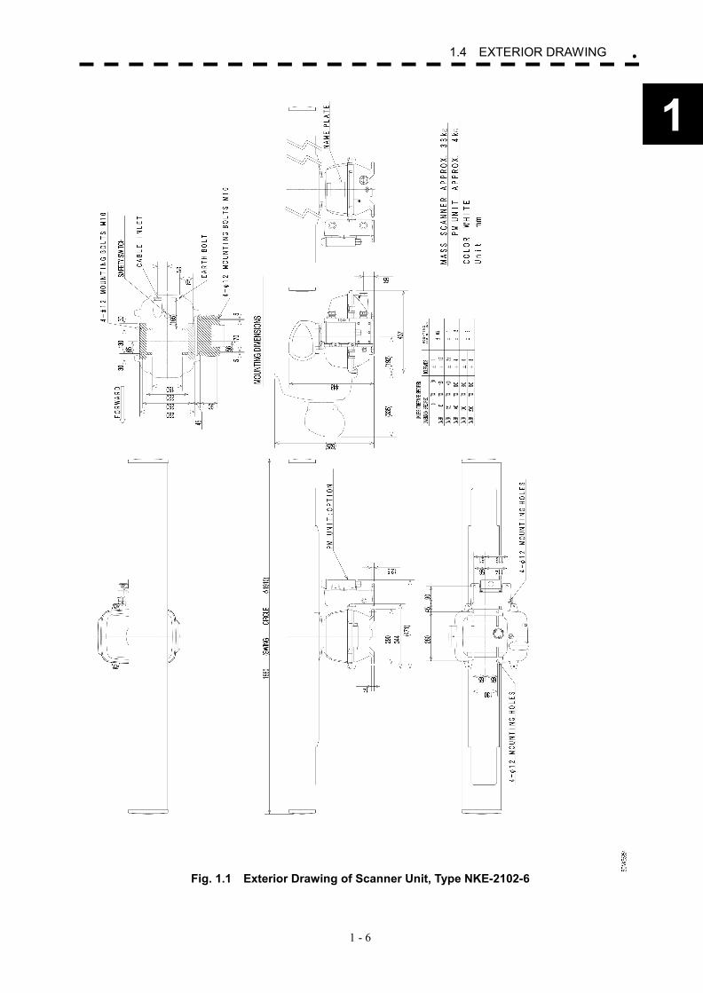
Fig. 1.1 Exterior Drawing of Scanner Unit, Type NKE-2102-6
1 - 7
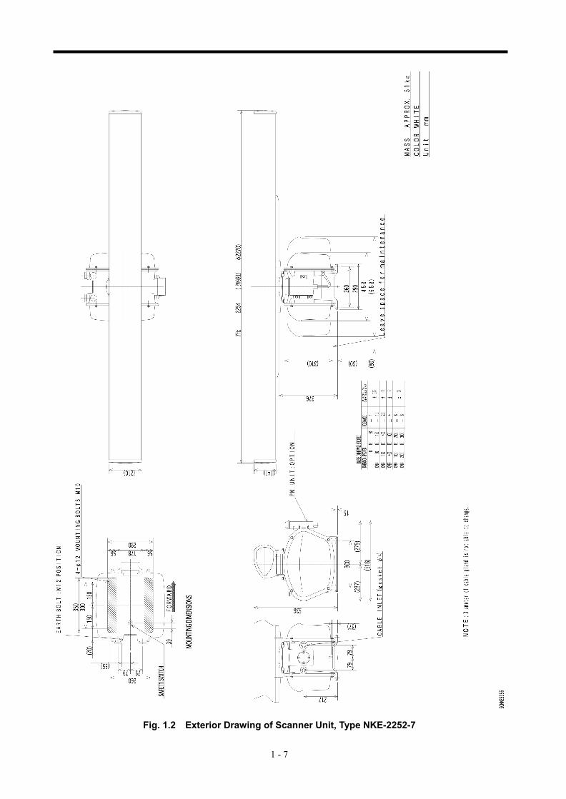
Fig. 1.2 Exterior Drawing of Scanner Unit, Type NKE-2252-7
1 - 8
1.4 EXTERIOR DRAWING�
1
Fig. 1.3 Exterior Drawing of Scanner Unit, Type NKE-2252-9
1 - 9
Fig. 1.4 Exterior Drawing of Scanner Unit, Type NKE-1075
1 - 10
1.4 EXTERIOR DRAWING�
1
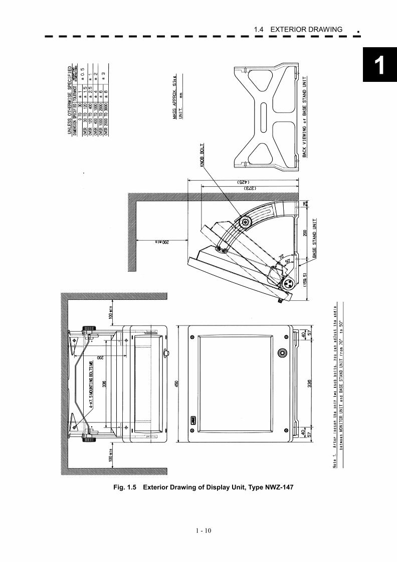
Fig. 1.5 Exterior Drawing of Display Unit, Type NWZ-147
1 - 11
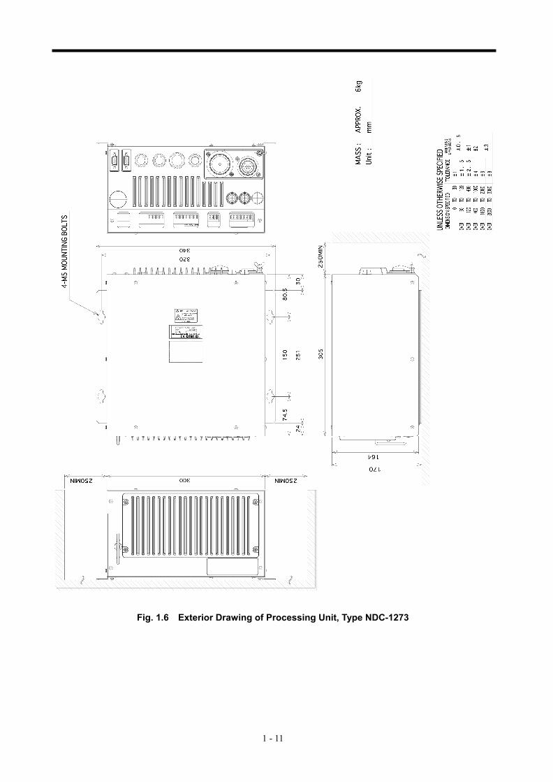
Fig. 1.6 Exterior Drawing of Processing Unit, Type NDC-1273
1 - 12
1.4 EXTERIOR DRAWING�
1
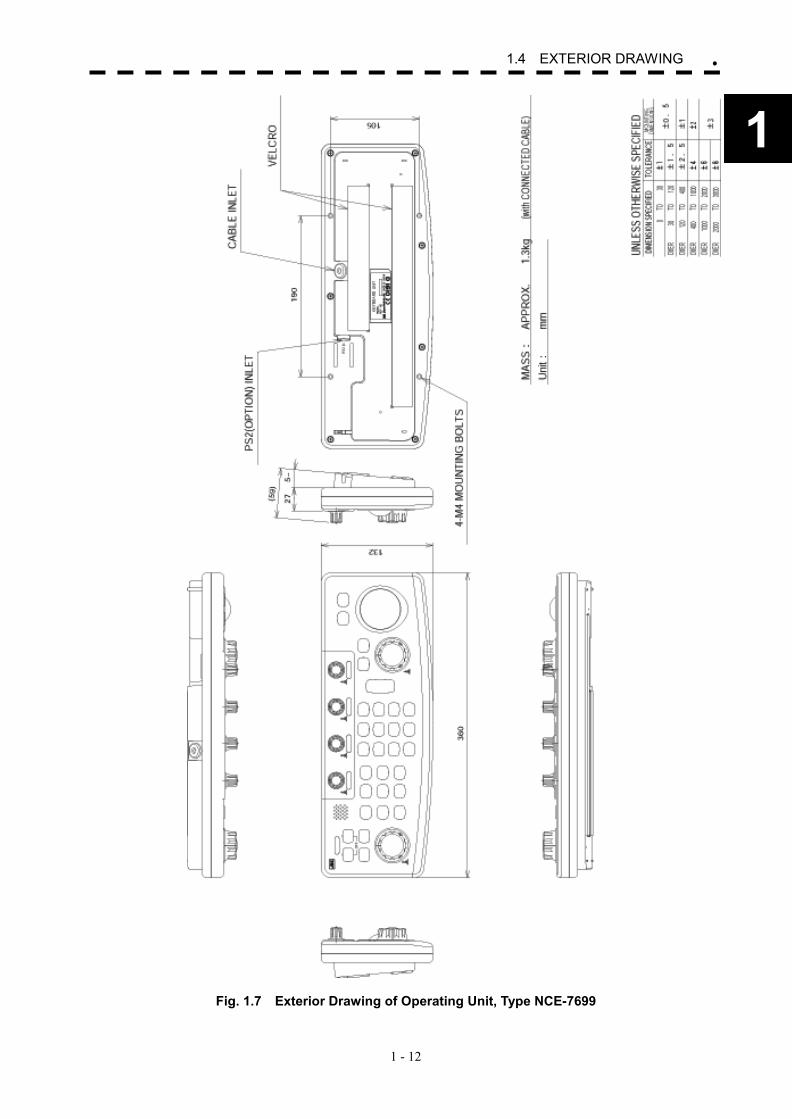
Fig. 1.7 Exterior Drawing of Operating Unit, Type NCE-7699
1 - 13
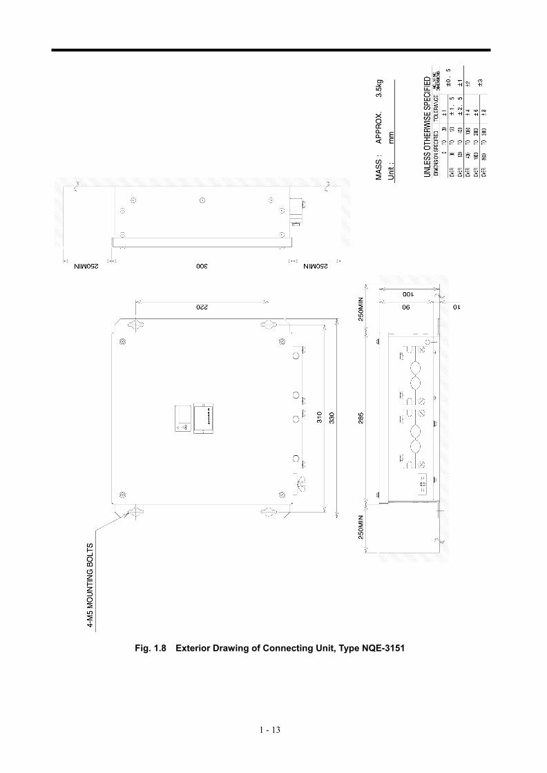
Fig. 1.8 Exterior Drawing of Connecting Unit, Type NQE-3151
1 - 14
11.5 GENERAL SYSTEM DIAGRAMS Fig. 1.9 General System Diagram of Radar, Type JMA-5310-6 Fig. 1.10 General System Diagram of Radar, Type JMA-5320-7 Fig. 1.11 General System Diagram of Radar, Type JMA-5320-9 Fig. 1.12 General System Diagram of Radar, Type JMA-5330-12
1 - 15
NKE-2102-6 空中線
NJU-64 パフォーマンスモニタ
(オプション)
19芯シールド付複合ケーブル
CFQ-6912-10最大径 φ14.5 (JRC支給)
NWZ-147 表示部
NCE-7699 操作部
NDC-1273 処理部
250V-TTYCS-1GPS
250V-DPYCYS-1.25LOG
250V-MPYCYS-5GYRO NCT-59 NSK UNIT
(オプション)
NCA-877W ARPA UNIT
(オプション)
NDB-34 PLOTTER UNIT
(オプション)
船内電源DC24V
NBA-3308 整流器
(オプション)
CFQ-6911最大径 φ10 (JRC支給) 5m
船内電源AC100/110/115V 50/60Hz 1φ
250V-DPYCYS-5.5
NQA-4250 AIS I/F UNIT
(オプション)
(JRC支給) 5m
(JRC支給) 5m
(JRC支給) 5m
(JRC支給) 5m
AC200/220/230V 50/60Hz 1φ
NCD-4510 指示機
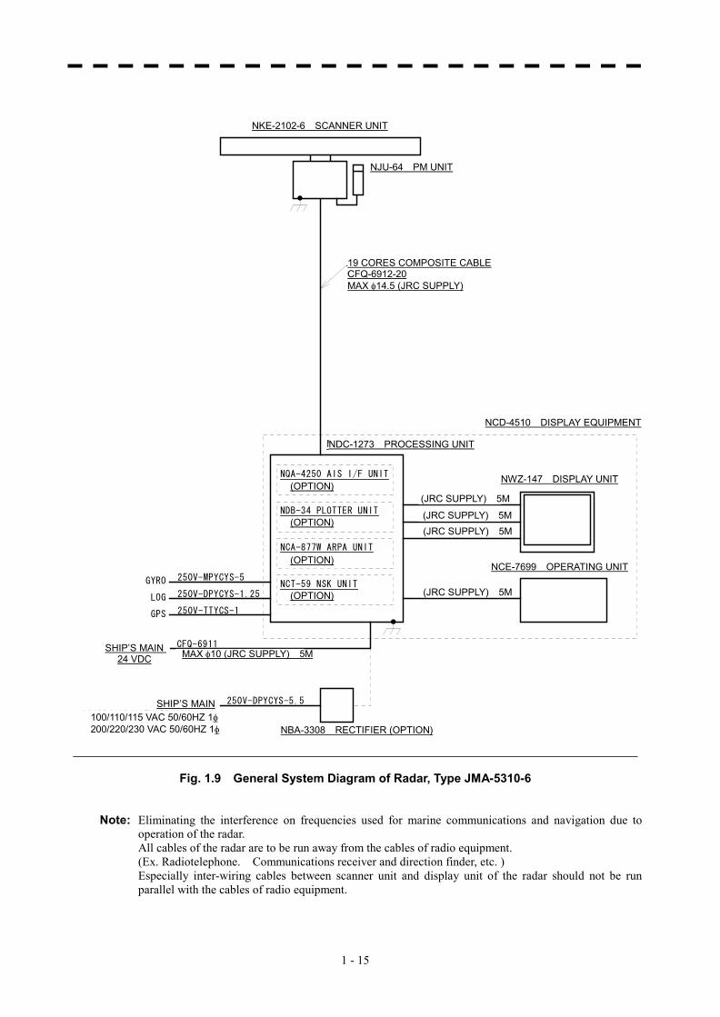
Fig. 1.9 General System Diagram of Radar, Type JMA-5310-6 Note: Eliminating the interference on frequencies used for marine communications and navigation due to
operation of the radar. All cables of the radar are to be run away from the cables of radio equipment. (Ex. Radiotelephone. Communications receiver and direction finder, etc. ) Especially inter-wiring cables between scanner unit and display unit of the radar should not be run
parallel with the cables of radio equipment.
NJU-64 PM UNIT
NKE-2102-6 SCANNER UNIT
19 CORES COMPOSITE CABLE CFQ-6912-20 MAX �14.5 (JRC SUPPLY)
NDC-1273 PROCESSING UNIT
NCD-4510 DISPLAY EQUIPMENT
(OPTION)(JRC SUPPLY) 5M
(JRC SUPPLY) 5M (JRC SUPPLY) 5M
(JRC SUPPLY) 5M
NWZ-147 DISPLAY UNIT
NCE-7699 OPERATING UNIT
SHIP’S MAIN 24 VDC MAX �10 (JRC SUPPLY) 5M
SHIP’S MAIN
NBA-3308 RECTIFIER (OPTION)
(OPTION)
(OPTION)
(OPTION)
100/110/115 VAC 50/60HZ 1� 200/220/230 VAC 50/60HZ 1�
1 - 16
1.5 GENERAL SYSTEM DIAGRAM�
1
NKE-2252-7 空中線
NJU-64 パフォーマンスモニタ
(オプション)
19芯シールド付複合ケーブル
CFQ-6912-10最大径 φ14.5 (JRC支給)
NWZ-147 表示部
NCE-7699 操作部
NDC-1273 処理部
250V-TTYCS-1GPS
250V-DPYCYS-1.25LOG
250V-MPYCYS-5GYRO NCT-59 NSK UNIT
(オプション)
NCA-877W ARPA UNIT
(オプション)
NDB-34 PLOTTER UNIT
(オプション)
船内電源DC24V
NBA-3308 整流器
(オプション)
CFQ-6911最大径 φ10 (JRC支給) 5m
船内電源AC100/110/115V 50/60Hz 1φ
250V-DPYCYS-5.5
NQA-4250 AIS I/F UNIT
(オプション)
(JRC支給) 5m
(JRC支給) 5m
(JRC支給) 5m
(JRC支給) 5m
AC200/220/230V 50/60Hz 1φ
NCD-4510 指示機
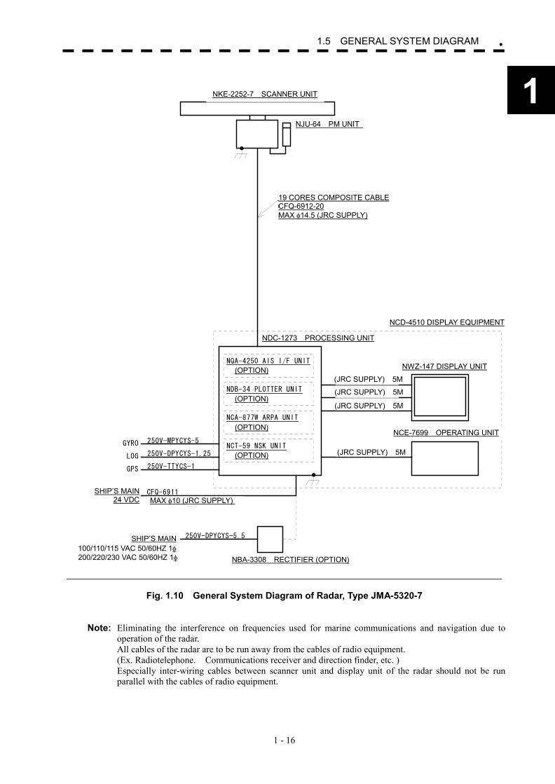
Fig. 1.10 General System Diagram of Radar, Type JMA-5320-7 Note: Eliminating the interference on frequencies used for marine communications and navigation due to
operation of the radar. All cables of the radar are to be run away from the cables of radio equipment. (Ex. Radiotelephone. Communications receiver and direction finder, etc. ) Especially inter-wiring cables between scanner unit and display unit of the radar should not be run
parallel with the cables of radio equipment.
NJU-64 PM UNIT
NKE-2252-7 SCANNER UNIT
19 CORES COMPOSITE CABLE CFQ-6912-20 MAX �14.5 (JRC SUPPLY)
NDC-1273 PROCESSING UNIT
NCD-4510 DISPLAY EQUIPMENT
(JRC SUPPLY) 5M
(JRC SUPPLY) 5M
(JRC SUPPLY) 5M
(JRC SUPPLY) 5M
NWZ-147 DISPLAY UNIT
NCE-7699 OPERATING UNIT
SHIP’S MAIN 24 VDC MAX �10 (JRC SUPPLY)
5M
SHIP’S MAIN
NBA-3308 RECTIFIER (OPTION)
(OPTION)
(OPTION)
(OPTION)
(OPTION)
100/110/115 VAC 50/60HZ 1� 200/220/230 VAC 50/60HZ 1�
1 - 17
NKE-2252-9 空中線
NJU-64 パフォーマンスモニタ
(オプション)
19芯シールド付複合ケーブル
CFQ-6912-10最大径 φ14.5 (JRC支給)
NWZ-147 表示部
NCE-7699 操作部
NDC-1273 処理部
250V-TTYCS-1GPS
250V-DPYCYS-1.25LOG
250V-MPYCYS-5GYRO NCT-59 NSK UNIT
(オプション)
NCA-877W ARPA UNIT
(オプション)
NDB-34 PLOTTER UNIT
(オプション)
船内電源DC24V
NBA-3308 整流器
(オプション)
CFQ-6911最大径 φ10 (JRC支給) 5m
船内電源AC100/110/115V 50/60Hz 1φ
250V-DPYCYS-5.5
NQA-4250 AIS I/F UNIT
(オプション)
(JRC支給) 5m
(JRC支給) 5m
(JRC支給) 5m
(JRC支給) 5m
AC200/220/230V 50/60Hz 1φ
NCD-4510 指示機
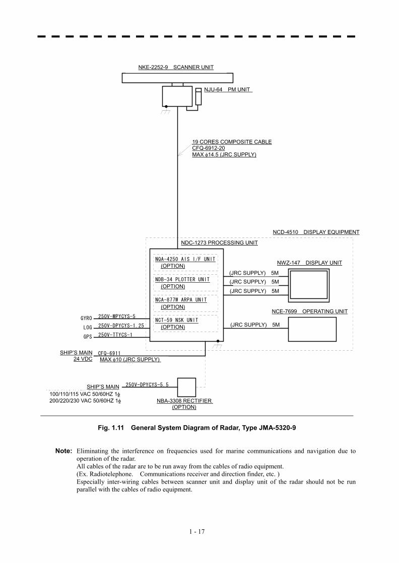
Fig. 1.11 General System Diagram of Radar, Type JMA-5320-9 Note: Eliminating the interference on frequencies used for marine communications and navigation due to
operation of the radar. All cables of the radar are to be run away from the cables of radio equipment. (Ex. Radiotelephone. Communications receiver and direction finder, etc. ) Especially inter-wiring cables between scanner unit and display unit of the radar should not be run
parallel with the cables of radio equipment.
NKE-2252-9 SCANNER UNIT
19 CORES COMPOSITE CABLE CFQ-6912-20 MAX �14.5 (JRC SUPPLY)
NDC-1273 PROCESSING UNIT
NCD-4510 DISPLAY EQUIPMENT
(JRC SUPPLY) 5M (JRC SUPPLY) 5M
(JRC SUPPLY) 5M
(JRC SUPPLY) 5M
NWZ-147 DISPLAY UNIT
NCE-7699 OPERATING UNIT
SHIP’S MAIN24 VDC MAX �10 (JRC SUPPLY)
5M
SHIP’S MAIN
NBA-3308 RECTIFIER (OPTION)
(OPTION)
(OPTION)
(OPTION)
(OPTION)
100/110/115 VAC 50/60HZ 1� 200/220/230 VAC 50/60HZ 1�
NJU-64 PM UNIT
1 - 18
1.5 GENERAL SYSTEM DIAGRAM�
1
NKE-1075 空中線
NJU-63 パフォーマンスモニタ
(オプション)
14芯シールド付複合ケーブル
H-2695110056最大径 φ23 (JRC支給)
NQE-3151 接続ユニット660V-DPYCYS-5.5AC100/110V 50/60Hz 1φAC220/230V 50/60Hz 1φ
船内電源
19芯シールド付複合ケーブル
CFQ-6912-10最大径 φ14.5 (JRC支給)
NWZ-147 表示部
NCE-7699 操作部
NDC-1273 処理部
250V-TTYCS-1GPS
250V-DPYCYS-1.25LOG
250V-MPYCYS-5GYRO NCT-59 NSK UNIT
(オプション)
NCA-877W ARPA UNIT
(オプション)
NDB-34 PLOTTER UNIT
(オプション)
船内電源DC24V
NBA-3308 整流器
(オプション)
CFQ-6911最大径 φ10 (JRC支給) 5m
船内電源AC100/110/115V 50/60Hz 1φ
250V-DPYCYS-5.5
NQA-4250 AIS I/F UNIT
(オプション)
(JRC支給) 5m
(JRC支給) 5m
(JRC支給) 5m
(JRC支給) 5m
AC200/220/230V 50/60Hz 1φ
NCD-4510 指示機
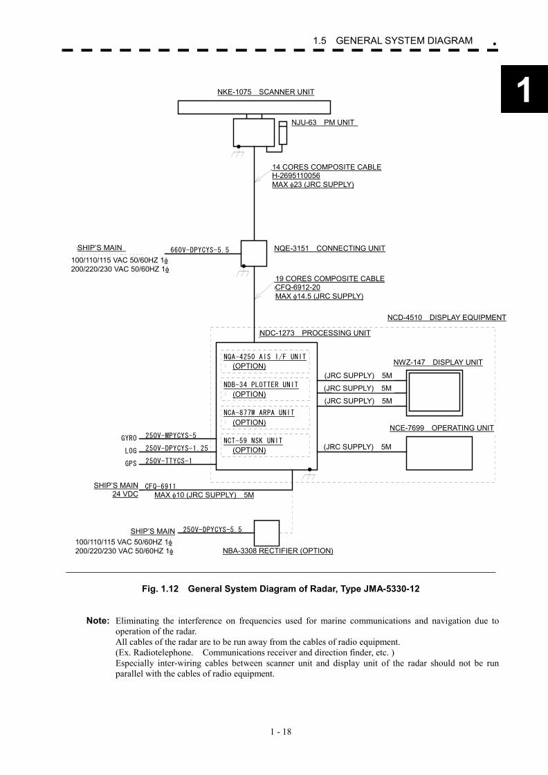
Fig. 1.12 General System Diagram of Radar, Type JMA-5330-12 Note: Eliminating the interference on frequencies used for marine communications and navigation due to
operation of the radar. All cables of the radar are to be run away from the cables of radio equipment. (Ex. Radiotelephone. Communications receiver and direction finder, etc. ) Especially inter-wiring cables between scanner unit and display unit of the radar should not be run
parallel with the cables of radio equipment.
NKE-1075 SCANNER UNIT
14 CORES COMPOSITE CABLE H-2695110056 MAX �23 (JRC SUPPLY)
NDC-1273 PROCESSING UNIT
NCD-4510 DISPLAY EQUIPMENT
(JRC SUPPLY) 5M
(JRC SUPPLY) 5M
(JRC SUPPLY) 5M
(JRC SUPPLY) 5M
NWZ-147 DISPLAY UNIT
NCE-7699 OPERATING UNIT
SHIP’S MAIN24 VDC MAX �10 (JRC SUPPLY) 5M
SHIP’S MAIN
NBA-3308 RECTIFIER (OPTION)
(OPTION)
(OPTION)
(OPTION)
(OPTION)
SHIP’S MAIN NQE-3151 CONNECTING UNIT
19 CORES COMPOSITE CABLE CFQ-6912-20 MAX �14.5 (JRC SUPPLY)
100/110/115 VAC 50/60HZ 1� 200/220/230 VAC 50/60HZ 1�
100/110/115 VAC 50/60HZ 1� 200/220/230 VAC 50/60HZ 1�
NJU-63 PM UNIT

SECTION 2 NAMES AND FUNCTIONS OF CONTROL PANEL SWITCHES
AND FUNCTIONS OF SOFTWARE BUTTONS
2.1 NAMES AND FUNCTIONS OF CONTROL
PANEL SWITCHES ...........................................1 2.2 FUNCTIONS OF SOFTWARE BUTTONS ........7
2─1
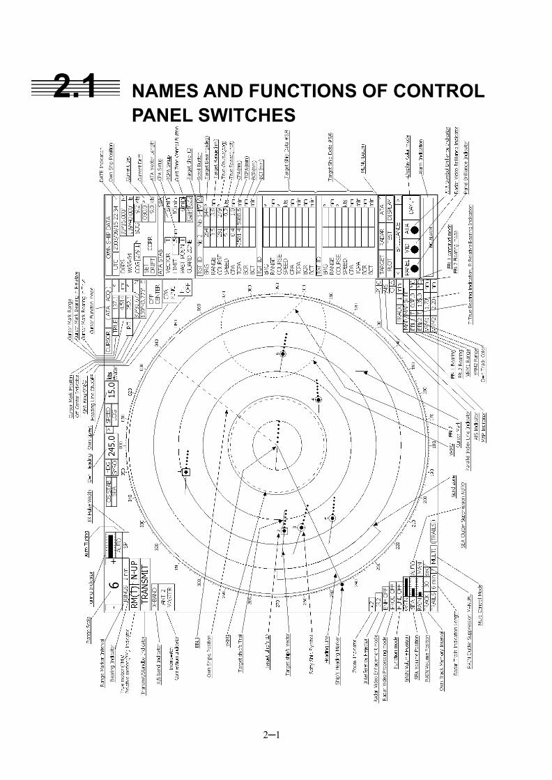
2.1 NAMES AND FUNCTIONS OF CONTROL PANEL SWITCHES
Example of Display
2─2
2
2.1 NAMES AND FUNCTIONS OF CONTROL ��
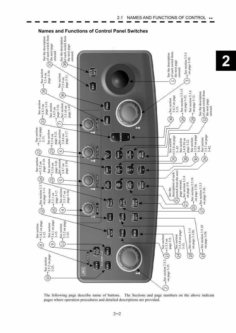
Names and Functions of Control Panel Switches
The following page describe name of buttons. The Sections and page numbers on the above indicate pages where operation procedures and detailed descriptions are provided.
See
the
desc
riptio
n of
eac
h sw
itch
from
th
e ne
xt p
age
onw
ard.
See
sect
ion
3.5.
4 on
pag
e 3-
30.
See
the
desc
riptio
n of
eac
h sw
itch
from
th
e ne
xt p
age
onw
ard.
See
the
desc
riptio
n of
eac
h sw
itch
from
th
e ne
xt p
age
onw
ard.
See
sect
ion
3.4.
3 on
pag
e 3-
15.
See
sect
ion
3.5.
15
on p
age
3-52
.
See
the
desc
riptio
n of
eac
h sw
itch
from
th
e ne
xt p
age
onw
ard.
See
sect
ion
3.5.
8 on
pag
e 3-
.43
See
sect
ion
3.4.
9/10
on
page
3-2
2.
See
sect
ion
3.5.
9 on
pag
e 3-
44.
See
sect
ion
3.5.
7 on
pag
e 3-
42.
See
the
de
scrip
tion
of e
ach
switc
h fr
om th
e ne
xt
page
onw
ard.
Se
e se
ctio
n 3.
3.4
on p
age
3-9.
Se
e se
ctio
n 3.
5.18
on
pag
e 3-
58.
See
sect
ion
5.3.
5 on
pag
e 5-
26.
See
sect
ion
3.3.
3 on
pa
ge 3
-9.
See
sect
ion
3.5.
14 o
n pa
ge
3-51
.
See
sect
ion
3.11
on
pag
e 3-
120.
See
sect
ion
3.5.
18
on p
age
3-58
.
See
sect
ion
3.5.
2on
pag
e 3-
25.
See
sect
ion
3.5.
2 on
pag
e 3-
25.
See
sect
ion
3.4.
2 on
pag
e 3-
15.
See
sect
ion
3.4.
1 on
pag
e 3-
15.
See
sect
ion
3.5.
2 on
pag
e 3-
25.
See
sect
ion
3.3.
7 on
pag
e 3-
11.
See
sect
ion
5.3.
1 on
pa
ge 5
-17.
Se
e se
ctio
n 3.
5.17
on
page
3-5
6.
See
sect
ion
5.3.
2 on
pa
ge 5
-19.
Se
e se
ctio
n 3.
5.6
on
page
3-4
1.
See
sect
ion
3.4.
7 on
pa
ge 3
-19.
See
sect
ion
3.7
on p
age
3-71
. Se
e se
ctio
n 5.
3.4
on
page
5-2
1.
See
sect
ion
3.4.
6 on
pa
ge 3
-17.
See
sect
ion
3.4.
3 on
pa
ge 3
-15.
Se
e se
ctio
n 3.
4.5
on
page
3-1
6.
See
sect
ion
3.5.
10 o
n pa
ge 3
-47.
See
sect
ion
3.5.
4 on
pa
ge 3
-30.
See
sect
ion
3.5.
4 on
pa
ge 3
-31.
See
sect
ion
5.1.
6 on
pag
e 5-
12.
2─3
① Trackball Use this trackball to move the cursor mark to an arbitrary point. The trackball can be used for setting in each mode. For example, use it to specify the center of a floating EBL or the off-center position.
�For setting cursor, see section 3.10.3 on page 3-102.
② [EBL] (Electric Bearing Line) Control Rotates the bearing of an EBL. The selected EBL status switches back and forth between “center fixed” and “floating” each time the control is pressed.
�See section 3.5.2 on page 3-25.
③ [VRM] (Variable Range Marker) Control Changes the range of a VRM.
�See section 3.5.4 on page 3-30.
④ [MULTI] (Multi-function) Control Each time you press this control, you can change items registered in the multi-function control function. An item to switch to is shown put in parentheses in the lower left area of the screen. Give a long press of the control to open the setup screen for registering items. Give a long press of the control button again to close this setup screen.
�See section 3.5.17 on page 3-56.
⑤ [AUTO-RAIN] (Rain/Snow Clutter Suppression) Control Suppresses the clutter echo from rain or snow. To heighten a suppressing effect, turn the control clockwise. The clutter suppression mode switches back and forth between MANUAL and AUTO each time the control is pressed.
�See section 3.4.7 on page 3-19.
⑥ [AUTO-SEA] (Sea Clutter Suppression) Control Suppresses the clutter echo from the sea surface. To heighten a suppressing effect, turn the control clockwise. The clutter suppression mode switches back and forth between MANUAL and AUTO each time the control is pressed.
�See section 3.4.6 on page 3-17.
⑦ [GAIN/PL] (Receiving Sensitivity/Pulse Width) Control Controls the radar’s receiving sensitivity. To get higher sensitivity, turn the control clockwise. To change the transmitter pulse width, press the control.
�For sensitivity, see section 3.4.5 on page 3-16. �For pulse width, see section 3.5.10 on page 3-47.
⑧ [STBY] (Standby) Switch
Use this switch to change the power-off state to the power-on state, or the transmission state to the standby state. To turn off the power, press the [STBY] switch and [TX/PRF] switch together.
�See section 3.4.2 on page 3-15.
⑨ [TX/PRF] (Transmit/Transmitting Repetition Frequency) Switch PREHEAT at the upper left of the radar display changes to STANDBY about three minutes after the power is turned on. Then, press this switch to start transmission. To fine-tune the transmitting repetition frequency, press the switch during transmission.
2─4
2
2.1 NAMES AND FUNCTIONS OF CONTROL ��
Use of this function with the interference reflector function heightens an interference suppressing effect.
�See section 3.4.1 on page 3-15.
⑩ [EBL1] (Electric Bearing Line 1) Switch Use this switch to display and select EBL1. Holding down the switch for two seconds or more displays the menu for EBL1 setting.
�See section 3.5.2 on page 3-25. �For EBL1 setting, see section 3.5.3 on page 3-27 onward.
⑪ [EBL2] (Electric Bearing Line 2) Switch Use this switch to display and select EBL2. Holding down the switch for two seconds or more displays the menu for EBL2 setting.
�See section 3.5.2 on page 3-25. �For EBL2 setting, see section 3.5.3 on page 3-27 onward.
⑫ [ALARM ACK] (Alarm Acknowledgment) Switch
Use this switch to acknowledge a failure, target’s approach, or collision alarm. Press the switch to stop an audible alarm. If more than one alarm has occurred, the switch needs to be pressed the number of times equivalent to the number of alarms.
�See section 3.3.7 on page 3-11.
⑬ [PANEL] (Operation Panel Brilliance) Switch Controls the brilliance for the controls and switches on the operation panel. The brilliance changes cyclically each time the switch is pressed.
�See section 3.3.3 on page 3-9.
⑭ [MOB] (Marker) Switch A marker is set to the latitude and longitude of the own ship’s position at the point of pressing this switch. For example, use the switch to store the own ship’s position at the moment when somebody falls from the ship. Holding down the switch for two seconds or more erases the marker.
�See section 3.5.14 on page 3-51.
⑮ [ACQ] (Manual Acquisition) Switch Enables the manual ATA acquisition mode for the target on which the cursor sits.
�See section 5.3.1 on page 5-17.
⑯ [TGT CNCL] (Tracking Target Cancel) Switch Cancels the symbol and vector of a target under tracking, and stops tracking the target. Holding down the switch for two seconds or more erases all the acquisitions of ATA.
�See section 5.3.2 on page 5-19.
⑰ [TGT DATA] (Target Data Setup) Switch Use this switch to view the numeric data of the ATA under tracking or the currently displayed AIS.
�See section 5.3.5 on page 5-26.
2─5
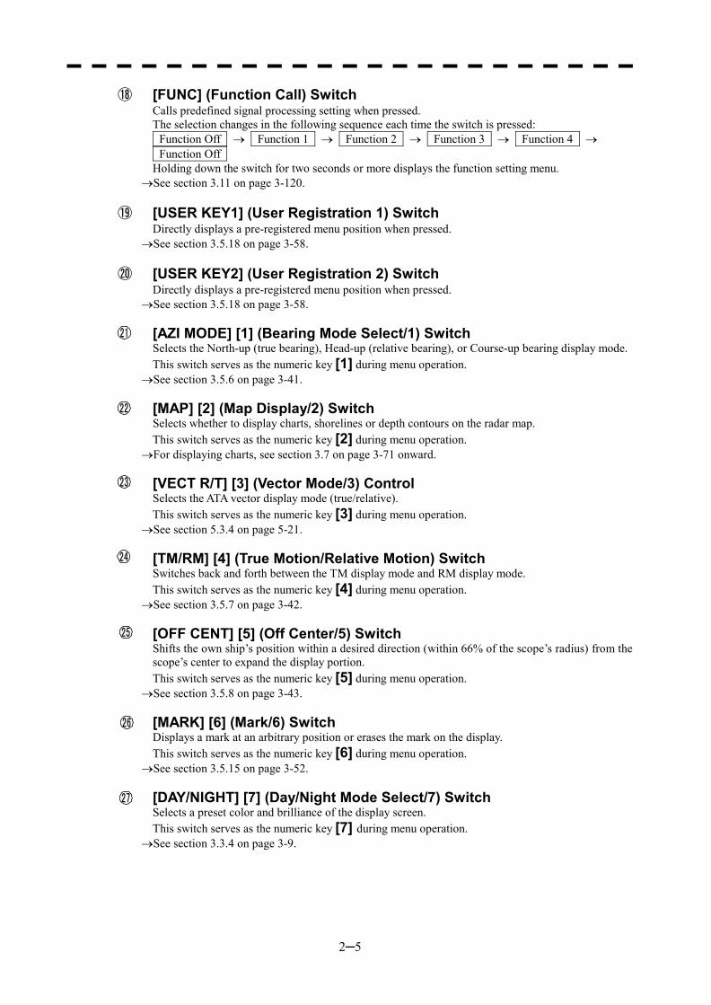
⑱ [FUNC] (Function Call) Switch Calls predefined signal processing setting when pressed. The selection changes in the following sequence each time the switch is pressed: Function Off � Function 1 � Function 2 � Function 3 � Function 4 � Function Off Holding down the switch for two seconds or more displays the function setting menu.
�See section 3.11 on page 3-120.
⑲ [USER KEY1] (User Registration 1) Switch Directly displays a pre-registered menu position when pressed.
�See section 3.5.18 on page 3-58.
⑳ [USER KEY2] (User Registration 2) Switch Directly displays a pre-registered menu position when pressed.
�See section 3.5.18 on page 3-58.
[AZI MODE] [1] (Bearing Mode Select/1) Switch Selects the North-up (true bearing), Head-up (relative bearing), or Course-up bearing display mode. This switch serves as the numeric key [1] during menu operation.
�See section 3.5.6 on page 3-41.
[MAP] [2] (Map Display/2) Switch Selects whether to display charts, shorelines or depth contours on the radar map. This switch serves as the numeric key [2] during menu operation.
�For displaying charts, see section 3.7 on page 3-71 onward.
[VECT R/T] [3] (Vector Mode/3) Control Selects the ATA vector display mode (true/relative). This switch serves as the numeric key [3] during menu operation.
�See section 5.3.4 on page 5-21.
[TM/RM] [4] (True Motion/Relative Motion) Switch Switches back and forth between the TM display mode and RM display mode. This switch serves as the numeric key [4] during menu operation.
�See section 3.5.7 on page 3-42.
[OFF CENT] [5] (Off Center/5) Switch Shifts the own ship’s position within a desired direction (within 66% of the scope’s radius) from the scope’s center to expand the display portion. This switch serves as the numeric key [5] during menu operation.
�See section 3.5.8 on page 3-43.
[MARK] [6] (Mark/6) Switch Displays a mark at an arbitrary position or erases the mark on the display. This switch serves as the numeric key [6] during menu operation.
�See section 3.5.15 on page 3-52.
[DAY/NIGHT] [7] (Day/Night Mode Select/7) Switch Selects a preset color and brilliance of the display screen. This switch serves as the numeric key [7] during menu operation.
�See section 3.3.4 on page 3-9.
21
22
23
24
25
27
26
2─6
2
2.1 NAMES AND FUNCTIONS OF CONTROL ��
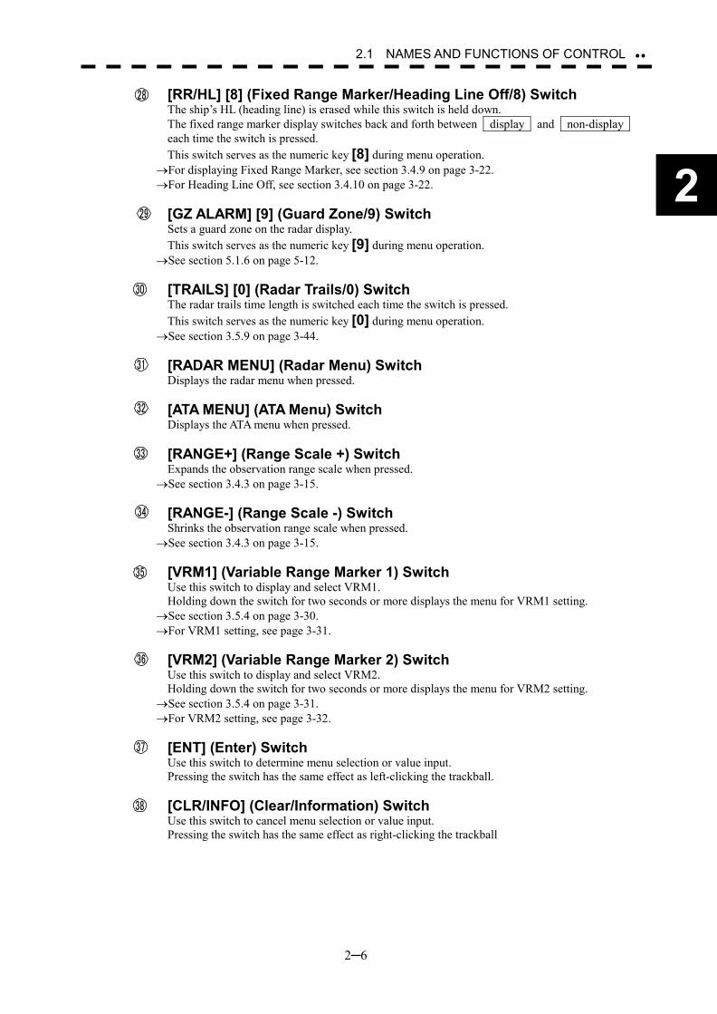
[RR/HL] [8] (Fixed Range Marker/Heading Line Off/8) Switch The ship’s HL (heading line) is erased while this switch is held down. The fixed range marker display switches back and forth between display and non-display each time the switch is pressed. This switch serves as the numeric key [8] during menu operation.
�For displaying Fixed Range Marker, see section 3.4.9 on page 3-22. �For Heading Line Off, see section 3.4.10 on page 3-22.
[GZ ALARM] [9] (Guard Zone/9) Switch
Sets a guard zone on the radar display. This switch serves as the numeric key [9] during menu operation.
�See section 5.1.6 on page 5-12.
[TRAILS] [0] (Radar Trails/0) Switch The radar trails time length is switched each time the switch is pressed. This switch serves as the numeric key [0] during menu operation.
�See section 3.5.9 on page 3-44.
[RADAR MENU] (Radar Menu) Switch Displays the radar menu when pressed.
[ATA MENU] (ATA Menu) Switch Displays the ATA menu when pressed.
[RANGE+] (Range Scale +) Switch Expands the observation range scale when pressed.
�See section 3.4.3 on page 3-15.
[RANGE-] (Range Scale -) Switch Shrinks the observation range scale when pressed.
�See section 3.4.3 on page 3-15.
[VRM1] (Variable Range Marker 1) Switch Use this switch to display and select VRM1. Holding down the switch for two seconds or more displays the menu for VRM1 setting.
�See section 3.5.4 on page 3-30. �For VRM1 setting, see page 3-31.
[VRM2] (Variable Range Marker 2) Switch
Use this switch to display and select VRM2. Holding down the switch for two seconds or more displays the menu for VRM2 setting.
�See section 3.5.4 on page 3-31. �For VRM2 setting, see page 3-32.
[ENT] (Enter) Switch
Use this switch to determine menu selection or value input. Pressing the switch has the same effect as left-clicking the trackball.
[CLR/INFO] (Clear/Information) Switch Use this switch to cancel menu selection or value input. Pressing the switch has the same effect as right-clicking the trackball
28
29
30
31
32
33
34
35
36
37
38
2─7
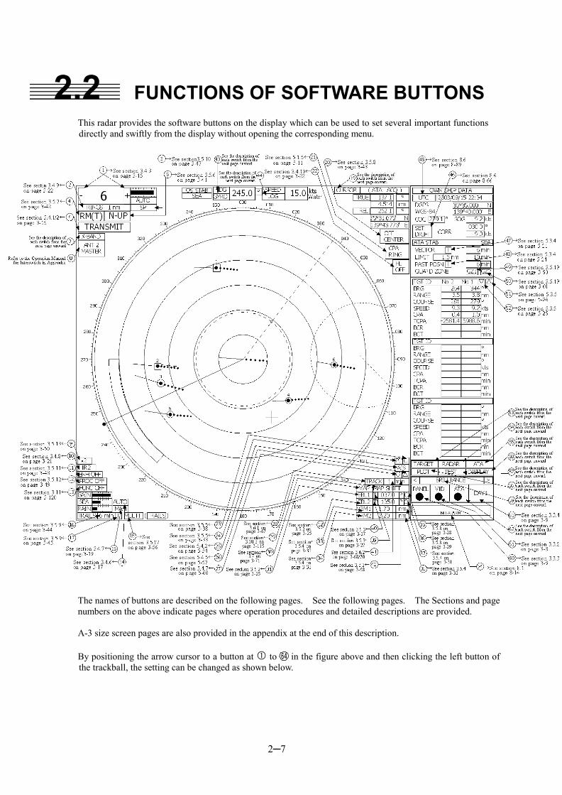
2.2 FUNCTIONS OF SOFTWARE BUTTONS
This radar provides the software buttons on the display which can be used to set several important functions directly and swiftly from the display without opening the corresponding menu.
The names of buttons are described on the following pages. See the following pages. The Sections and page numbers on the above indicate pages where operation procedures and detailed descriptions are provided. A-3 size screen pages are also provided in the appendix at the end of this description. By positioning the arrow cursor to a button at � to in the figure above and then clicking the left button of the trackball, the setting can be changed as shown below.
64
2─8
2
2.1 NAMES AND FUNCTIONS OF CONTROL ��
①: Range selection Switches a radar range. “+”: Increments the range scale level by 1. (96 or 120 nm at maximum) “-”: Decrements the range scale level by 1. (0.125 nm at minimum)
�See section 3.4.3 on page 3-15.
②: Selection of RINGS display Turns on/off the fixed range marker display. While it is on, the range ring interval is displayed. While it is off, “OFF” is displayed.
�See section 3.4.9 on page 3-22.
③: Selection of transmitter pulse width Selects a transmitter pulse width. There are three types of pulses, short pulse (SP), middle pulse (MP), and long pulse (LP). The pulse width to be selected varies depending on the current range. If the pulse width cannot be changed, the display disappears. The pulse width setting is stored for each range.
�See section 3.5.10 on page 3-47.
④: Selection of motion mode Selects the true motion (TM) or relative motion (RM) mode for the radar display. The display switches back and forth between “TM” and “RM” each time the button is clicked. RM (R) indicates relative trails; RM (T) indicates true trails.
�See section 3.5.7 on page 3-42.
⑤: Selection of bearing mode Selects North-up (true bearing), Head-up (relative bearing), or Course-up bearing mode. This button operates similarly to the “AZI MODE” switch. The selection changes in the following sequence each time the button is clicked: N UP � C UP � H UP
�See section 3.5.6 on page 3-41.
⑥: Selection of Transmit/Standby PREHEAT at the upper left of the radar display changes to STANDBY about three minutes after the power is turned on. STANDBY : Indicates the standby state. Clicking the button in this state changes to the
transmission state. TRANSMIT : Indicates the transmission state. Clicking the button in this state changes to the
standby state. �For how to start transmission, see Section 3.4.1 on page 3-15. �For how to stop transmission, see Section 3.4.2 on page 3-15.
⑦: Indication of band
This button is fixed depending on the type of the antenna. X-BAND or S-BAND is displayed.
⑧: Change of interswitch connection This button is displayed when an interswitch is connected. The display indicates the connection between the indicator and the scanner. Clicking the button displays the menu for changing the indicator-scanner connection. The indicator-scanner connection cannot be changed unless the master indicator is in standby state.
�For the setting procedure, refer to the Operation Manual for Interswitch in Appendix. The interswitch is an option. Only when an interswitch is connected, this button is to be displayed.
⑨: Zoom selection Doubles the size of display specified with the cursor.
�See section 3.5.13 on page 3-50.
2─9
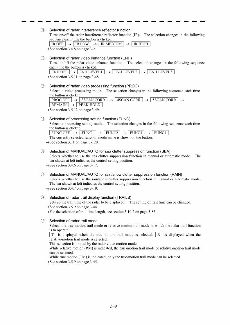
⑩: Selection of radar interference reflector function Turns on/off the radar interference reflector function (IR). The selection changes in the following sequence each time the button is clicked. IR OFF � IR LOW � IR MEDIUM � IR HIGH
�See section 3.4.8 on page 3-21.
⑪: Selection of radar video enhance function (ENH) Turns on/off the radar video enhance function. The selection changes in the following sequence each time the button is clicked: ENH OFF � ENH LEVEL1 � ENH LEVEL2 � ENH LEVEL3
�See section 3.5.11 on page 3-48.
⑫: Selection of radar video processing function (PROC) Selects a video processing mode. The selection changes in the following sequence each time the button is clicked: PROC OFF � 3SCAN CORR � 4SCAN CORR � 5SCAN CORR � REMAIN � PEAK HOLD
�See section 3.5.12 on page 3-49.
⑬: Selection of processing setting function (FUNC) Selects a processing setting mode. The selection changes in the following sequence each time the button is clicked: FUNC OFF � FUNC1 � FUNC2 � FUNC3 � FUNC4 The currently selected function mode name is shown on the button.
�See section 3.11 on page 3-120.
⑭: Selection of MANUAL/AUTO for sea clutter suppression function (SEA) Selects whether to use the sea clutter suppression function in manual or automatic mode. The bar shown at left indicates the control setting position.
�See section 3.4.6 on page 3-17.
⑮: Selection of MANUAL/AUTO for rain/snow clutter suppression function (RAIN) Selects whether to use the rain/snow clutter suppression function in manual or automatic mode. The bar shown at left indicates the control setting position.
�See section 3.4.7 on page 3-19.
⑯: Selection of radar trail display function (TRAILS) Sets up the trail time of the radar to be displayed. The setting of trail time can be changed.
�See section 3.5.9 on page 3-44. �For the selection of trail time length, see section 3.10.2 on page 3-85.
⑰: Selection of radar trail mode
Selects the true-motion trail mode or relative-motion trail mode in which the radar trail function is to operate. T is displayed when the true-motion trail mode is selected; R is displayed when the relative-motion trail mode is selected. This selection is limited by the radar video motion mode. While relative motion (RM) is indicated, the true-motion trail mode or relative-motion trail mode can be selected.
While true motion (TM) is indicated, only the true-motion trail mode can be selected. �See section 3.5.9 on page 3-45.

2─10
2
2.1 NAMES AND FUNCTIONS OF CONTROL ��
⑱: Multi-function Control Mode Each time you press this button, you can change the item registered in the multi-function control function. A switched item is displayed put in parentheses. Give a long press of the control to open the setup screen for registering items. Give a long press of the control button again to close this setup screen.
�See section 3.5.17 on page 3-56. ⑲: Cursor mode selection
Selects a mode in which the cursor is to move. The selection changes in the following sequence each time the button is clicked: OFF � ACQ ATA � ACT AIS � TGT DATA � CANCEL � □ � OFF
⑳: Selection of off-center mode
This button operates similarly to the [OFF CENT] switch. To shift the center of the own ship to the cursor position, press the button to move the cursor and left-click. The center of the own ship can be shifted within 66% of the scope’s radius.
�See section 3.5.8 on page 3-43. : Selection of CPA RING display
Turns on/off the CPA RING display. CPA RING cannot be turned on while TRUE is selected for the vector mode.
�See section 5.1.5 on page 5-11.
: Selection of HL Off This button operates similarly to the [RR/HL] switch. The heading line (HL) display is off while the button is held down.
�See section 3.4.10 on page 3-22.
: Starting point mode of parallel cursor Determines whether the starting point of parallel cursor is placed at the center of the own ship or at an arbitrary position on the radar display screen. You can select from the following three types: C: CENTER, 0: OFFSET, and L: L/L FIX.
�See section 3.5.5 on page 3-38. : Selection of parallel cursor display
Turns on/off the parallel cursor display. The selection (on/off) changes each time the button is pressed.
�See section 3.5.5 on page 3-33.
: Selection of AIS display function Turns on/off the AIS display function. The selection status is changed each time the button is
pressed. �See section 5.4.2 on page 5-54. * This function is available only when the AIS I/F (option) is connected.
: Selection of AIS symbol display
Turns on/off the AIS symbol display. The selection (on/off) changes each time the button is pressed.
�See section 5.4.5 on page 5-57. * This function is available only when the AIS I/F (option) is connected.
: Selection of ARPA symbol display
Turns on/off the ARPA symbol display to distinguish the symbol from the AIS symbol. The selection changes each time the button is pressed.
�See section 5.4.7 on page 5-60. * This function is available only when the AIS I/F (option) is connected.
21
27
22
23
24
25
26
2─11
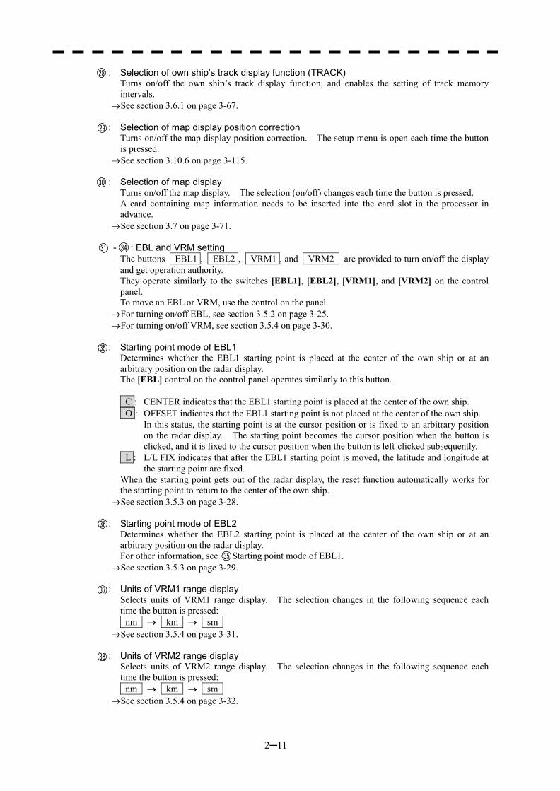
: Selection of own ship’s track display function (TRACK) Turns on/off the own ship’s track display function, and enables the setting of track memory intervals.
�See section 3.6.1 on page 3-67.
: Selection of map display position correction Turns on/off the map display position correction. The setup menu is open each time the button is pressed.
�See section 3.10.6 on page 3-115.
: Selection of map display Turns on/off the map display. The selection (on/off) changes each time the button is pressed. A card containing map information needs to be inserted into the card slot in the processor in advance.
�See section 3.7 on page 3-71.
- : EBL and VRM setting The buttons EBL1 , EBL2 , VRM1 , and VRM2 are provided to turn on/off the display and get operation authority. They operate similarly to the switches [EBL1], [EBL2], [VRM1], and [VRM2] on the control panel. To move an EBL or VRM, use the control on the panel.
�For turning on/off EBL, see section 3.5.2 on page 3-25. �For turning on/off VRM, see section 3.5.4 on page 3-30.
: Starting point mode of EBL1
Determines whether the EBL1 starting point is placed at the center of the own ship or at an arbitrary position on the radar display. The [EBL] control on the control panel operates similarly to this button. C : CENTER indicates that the EBL1 starting point is placed at the center of the own ship. O : OFFSET indicates that the EBL1 starting point is not placed at the center of the own ship.
In this status, the starting point is at the cursor position or is fixed to an arbitrary position on the radar display. The starting point becomes the cursor position when the button is clicked, and it is fixed to the cursor position when the button is left-clicked subsequently.
L : L/L FIX indicates that after the EBL1 starting point is moved, the latitude and longitude at the starting point are fixed.
When the starting point gets out of the radar display, the reset function automatically works for the starting point to return to the center of the own ship.
�See section 3.5.3 on page 3-28.
: Starting point mode of EBL2 Determines whether the EBL2 starting point is placed at the center of the own ship or at an arbitrary position on the radar display. For other information, see Starting point mode of EBL1.
�See section 3.5.3 on page 3-29.
: Units of VRM1 range display Selects units of VRM1 range display. The selection changes in the following sequence each time the button is pressed: nm � km � sm
�See section 3.5.4 on page 3-31.
: Units of VRM2 range display Selects units of VRM2 range display. The selection changes in the following sequence each time the button is pressed: nm � km � sm
�See section 3.5.4 on page 3-32.
28
29
30
31 34
35
35
36
37
38
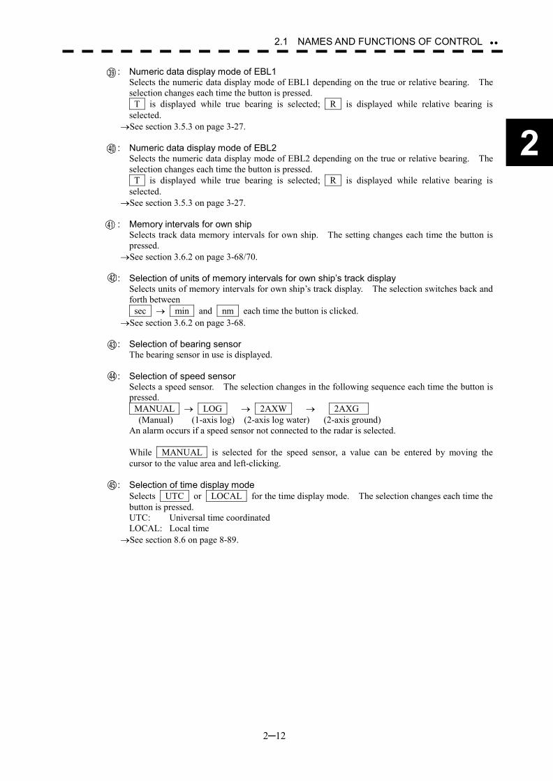
2─12
2
2.1 NAMES AND FUNCTIONS OF CONTROL ��
: Numeric data display mode of EBL1 Selects the numeric data display mode of EBL1 depending on the true or relative bearing. The selection changes each time the button is pressed. T is displayed while true bearing is selected; R is displayed while relative bearing is selected.
�See section 3.5.3 on page 3-27.
: Numeric data display mode of EBL2 Selects the numeric data display mode of EBL2 depending on the true or relative bearing. The selection changes each time the button is pressed. T is displayed while true bearing is selected; R is displayed while relative bearing is selected.
�See section 3.5.3 on page 3-27.
: Memory intervals for own ship Selects track data memory intervals for own ship. The setting changes each time the button is pressed.
�See section 3.6.2 on page 3-68/70.
: Selection of units of memory intervals for own ship’s track display Selects units of memory intervals for own ship’s track display. The selection switches back and forth between sec � min and nm each time the button is clicked.
�See section 3.6.2 on page 3-68.
: Selection of bearing sensor The bearing sensor in use is displayed.
: Selection of speed sensor Selects a speed sensor. The selection changes in the following sequence each time the button is pressed. MANUAL � LOG � 2AXW � 2AXG (Manual) (1-axis log) (2-axis log water) (2-axis ground) An alarm occurs if a speed sensor not connected to the radar is selected. While MANUAL is selected for the speed sensor, a value can be entered by moving the cursor to the value area and left-clicking.
: Selection of time display mode Selects UTC or LOCAL for the time display mode. The selection changes each time the button is pressed. UTC: Universal time coordinated LOCAL: Local time
�See section 8.6 on page 8-89.
43
44
45
39
40
41
42
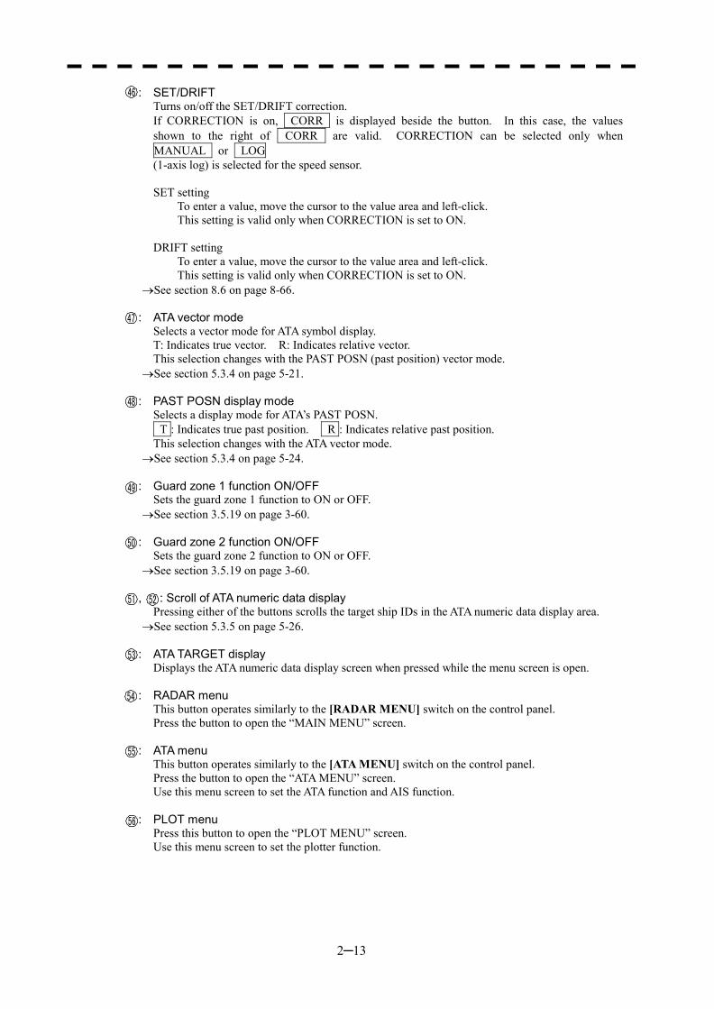
2─13
: SET/DRIFT Turns on/off the SET/DRIFT correction. If CORRECTION is on, CORR is displayed beside the button. In this case, the values shown to the right of CORR are valid. CORRECTION can be selected only when MANUAL or LOG (1-axis log) is selected for the speed sensor. SET setting
To enter a value, move the cursor to the value area and left-click. This setting is valid only when CORRECTION is set to ON.
DRIFT setting
To enter a value, move the cursor to the value area and left-click. This setting is valid only when CORRECTION is set to ON.
�See section 8.6 on page 8-66.
: ATA vector mode Selects a vector mode for ATA symbol display. T: Indicates true vector. R: Indicates relative vector. This selection changes with the PAST POSN (past position) vector mode.
�See section 5.3.4 on page 5-21.
: PAST POSN display mode Selects a display mode for ATA’s PAST POSN. T : Indicates true past position. R : Indicates relative past position. This selection changes with the ATA vector mode.
�See section 5.3.4 on page 5-24. : Guard zone 1 function ON/OFF
Sets the guard zone 1 function to ON or OFF. �See section 3.5.19 on page 3-60.
: Guard zone 2 function ON/OFF
Sets the guard zone 2 function to ON or OFF. �See section 3.5.19 on page 3-60.
, : Scroll of ATA numeric data display
Pressing either of the buttons scrolls the target ship IDs in the ATA numeric data display area. �See section 5.3.5 on page 5-26.
: ATA TARGET display
Displays the ATA numeric data display screen when pressed while the menu screen is open. : RADAR menu
This button operates similarly to the [RADAR MENU] switch on the control panel. Press the button to open the “MAIN MENU” screen.
: ATA menu This button operates similarly to the [ATA MENU] switch on the control panel. Press the button to open the “ATA MENU” screen. Use this menu screen to set the ATA function and AIS function.
: PLOT menu Press this button to open the “PLOT MENU” screen. Use this menu screen to set the plotter function.
46
47
48
49
50
51 52
53
54
55
56
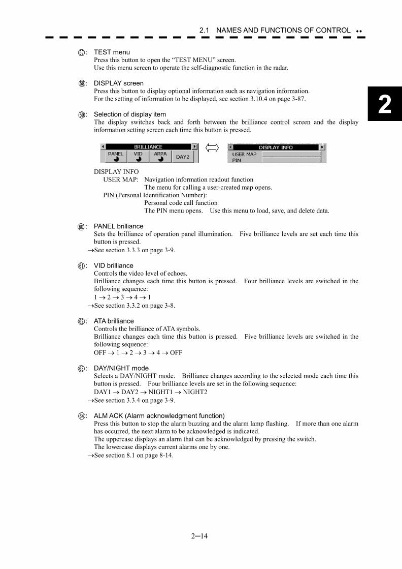
2─14
2
2.1 NAMES AND FUNCTIONS OF CONTROL ��
: TEST menu Press this button to open the “TEST MENU” screen. Use this menu screen to operate the self-diagnostic function in the radar.
: DISPLAY screen Press this button to display optional information such as navigation information. For the setting of information to be displayed, see section 3.10.4 on page 3-87.
: Selection of display item The display switches back and forth between the brilliance control screen and the display information setting screen each time this button is pressed.
DISPLAY INFO
USER MAP: Navigation information readout function The menu for calling a user-created map opens. PIN (Personal Identification Number): Personal code call function The PIN menu opens. Use this menu to load, save, and delete data.
: PANEL brilliance Sets the brilliance of operation panel illumination. Five brilliance levels are set each time this button is pressed.
�See section 3.3.3 on page 3-9.
: VID brilliance Controls the video level of echoes. Brilliance changes each time this button is pressed. Four brilliance levels are switched in the following sequence: 1 � 2 � 3 � 4 � 1
�See section 3.3.2 on page 3-8.
: ATA brilliance Controls the brilliance of ATA symbols. Brilliance changes each time this button is pressed. Five brilliance levels are switched in the following sequence: OFF � 1 � 2 � 3 � 4 � OFF
: DAY/NIGHT mode Selects a DAY/NIGHT mode. Brilliance changes according to the selected mode each time this button is pressed. Four brilliance levels are set in the following sequence: DAY1 � DAY2 � NIGHT1 � NIGHT2
�See section 3.3.4 on page 3-9.
: ALM ACK (Alarm acknowledgment function) Press this button to stop the alarm buzzing and the alarm lamp flashing. If more than one alarm has occurred, the next alarm to be acknowledged is indicated. The uppercase displays an alarm that can be acknowledged by pressing the switch. The lowercase displays current alarms one by one.
�See section 8.1 on page 8-14.
57
58
59
61
60
62
63
64

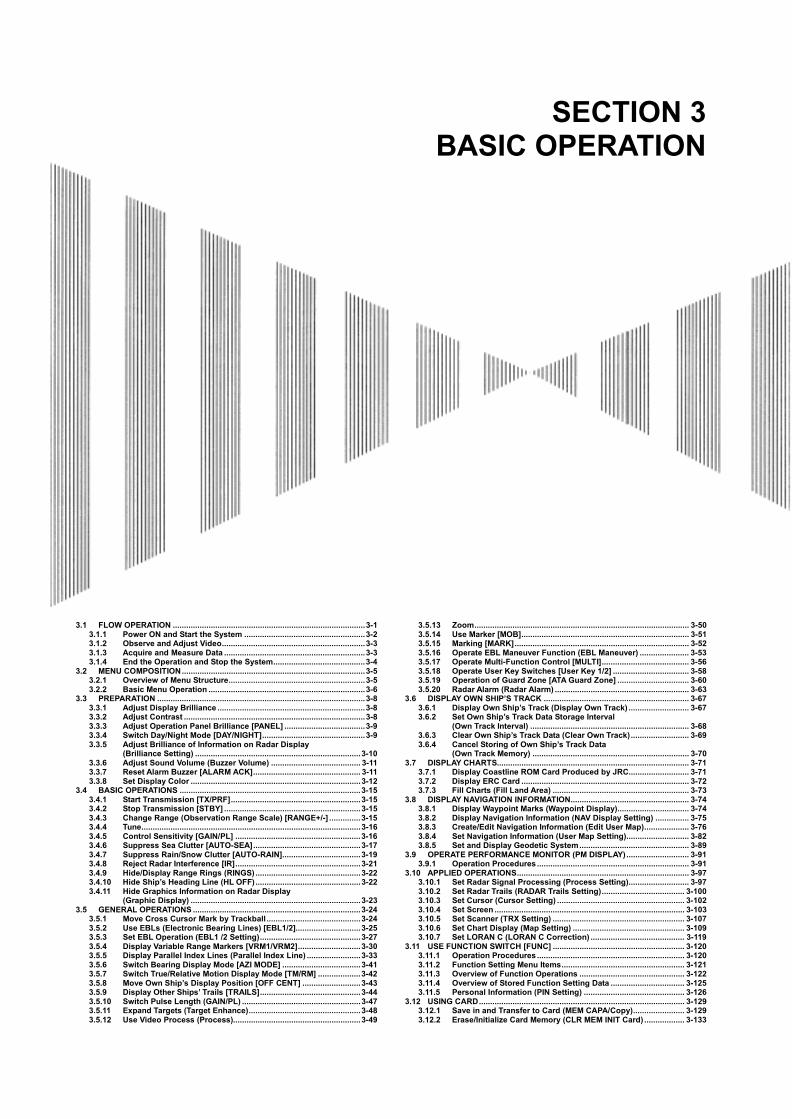
SECTION 3 BASIC OPERATION
3.1 FLOW OPERATION ......................................................................................3-1
3.1.1 Power ON and Start the System ......................................................3-2 3.1.2 Observe and Adjust Video................................................................3-3 3.1.3 Acquire and Measure Data ...............................................................3-3 3.1.4 End the Operation and Stop the System.........................................3-4
3.2 MENU COMPOSITION..................................................................................3-5 3.2.1 Overview of Menu Structure.............................................................3-5 3.2.2 Basic Menu Operation ......................................................................3-6
3.3 PREPARATION .............................................................................................3-8 3.3.1 Adjust Display Brilliance ..................................................................3-8 3.3.2 Adjust Contrast .................................................................................3-8 3.3.3 Adjust Operation Panel Brilliance [PANEL] ....................................3-9 3.3.4 Switch Day/Night Mode [DAY/NIGHT]..............................................3-9 3.3.5 Adjust Brilliance of Information on Radar Display
(Brilliance Setting) ..........................................................................3-10 3.3.6 Adjust Sound Volume (Buzzer Volume) ........................................ 3-11 3.3.7 Reset Alarm Buzzer [ALARM ACK]................................................ 3-11 3.3.8 Set Display Color ............................................................................3-12
3.4 BASIC OPERATIONS .................................................................................3-15 3.4.1 Start Transmission [TX/PRF]..........................................................3-15 3.4.2 Stop Transmission [STBY] .............................................................3-15 3.4.3 Change Range (Observation Range Scale) [RANGE+/-] ..............3-15 3.4.4 Tune..................................................................................................3-16 3.4.5 Control Sensitivity [GAIN/PL] ........................................................3-16 3.4.6 Suppress Sea Clutter [AUTO-SEA]................................................3-17 3.4.7 Suppress Rain/Snow Clutter [AUTO-RAIN]...................................3-19 3.4.8 Reject Radar Interference [IR]........................................................3-21 3.4.9 Hide/Display Range Rings (RINGS) ...............................................3-22 3.4.10 Hide Ship’s Heading Line (HL OFF)...............................................3-22 3.4.11 Hide Graphics Information on Radar Display
(Graphic Display) ............................................................................3-23 3.5 GENERAL OPERATIONS ...........................................................................3-24
3.5.1 Move Cross Cursor Mark by Trackball ..........................................3-24 3.5.2 Use EBLs (Electronic Bearing Lines) [EBL1/2].............................3-25 3.5.3 Set EBL Operation (EBL1 /2 Setting).............................................3-27 3.5.4 Display Variable Range Markers [VRM1/VRM2]............................3-30 3.5.5 Display Parallel Index Lines (Parallel Index Line) ........................3-33 3.5.6 Switch Bearing Display Mode [AZI MODE] ...................................3-41 3.5.7 Switch True/Relative Motion Display Mode [TM/RM] ...................3-42 3.5.8 Move Own Ship’s Display Position [OFF CENT] ..........................3-43 3.5.9 Display Other Ships’ Trails [TRAILS].............................................3-44 3.5.10 Switch Pulse Length (GAIN/PL) .....................................................3-47 3.5.11 Expand Targets (Target Enhance)..................................................3-48 3.5.12 Use Video Process (Process).........................................................3-49
3.5.13 Zoom................................................................................................ 3-50 3.5.14 Use Marker [MOB]........................................................................... 3-51 3.5.15 Marking [MARK].............................................................................. 3-52 3.5.16 Operate EBL Maneuver Function (EBL Maneuver) ...................... 3-53 3.5.17 Operate Multi-Function Control [MULTI]....................................... 3-56 3.5.18 Operate User Key Switches [User Key 1/2] .................................. 3-58 3.5.19 Operation of Guard Zone [ATA Guard Zone] ................................ 3-60 3.5.20 Radar Alarm (Radar Alarm) ............................................................ 3-63
3.6 DISPLAY OWN SHIP’S TRACK ................................................................. 3-67 3.6.1 Display Own Ship’s Track (Display Own Track) ........................... 3-67 3.6.2 Set Own Ship’s Track Data Storage Interval
(Own Track Interval) ....................................................................... 3-68 3.6.3 Clear Own Ship’s Track Data (Clear Own Track).......................... 3-69 3.6.4 Cancel Storing of Own Ship’s Track Data
(Own Track Memory) ...................................................................... 3-70 3.7 DISPLAY CHARTS...................................................................................... 3-71
3.7.1 Display Coastline ROM Card Produced by JRC........................... 3-71 3.7.2 Display ERC Card ........................................................................... 3-72 3.7.3 Fill Charts (Fill Land Area) ............................................................. 3-73
3.8 DISPLAY NAVIGATION INFORMATION..................................................... 3-74 3.8.1 Display Waypoint Marks (Waypoint Display)................................ 3-74 3.8.2 Display Navigation Information (NAV Display Setting) ............... 3-75 3.8.3 Create/Edit Navigation Information (Edit User Map).................... 3-76 3.8.4 Set Navigation Information (User Map Setting)............................ 3-82 3.8.5 Set and Display Geodetic System................................................. 3-89
3.9 OPERATE PERFORMANCE MONITOR (PM DISPLAY)............................ 3-91 3.9.1 Operation Procedures .................................................................... 3-91
3.10 APPLIED OPERATIONS............................................................................. 3-97 3.10.1 Set Radar Signal Processing (Process Setting)........................... 3-97 3.10.2 Set Radar Trails (RADAR Trails Setting)..................................... 3-100 3.10.3 Set Cursor (Cursor Setting) ......................................................... 3-102 3.10.4 Set Screen ..................................................................................... 3-103 3.10.5 Set Scanner (TRX Setting) ........................................................... 3-107 3.10.6 Set Chart Display (Map Setting) .................................................. 3-109 3.10.7 Set LORAN C (LORAN C Correction) .......................................... 3-119
3.11 USE FUNCTION SWITCH [FUNC] ........................................................... 3-120 3.11.1 Operation Procedures .................................................................. 3-120 3.11.2 Function Setting Menu Items....................................................... 3-121 3.11.3 Overview of Function Operations ............................................... 3-122 3.11.4 Overview of Stored Function Setting Data ................................. 3-125 3.11.5 Personal Information (PIN Setting) ............................................. 3-126
3.12 USING CARD............................................................................................ 3-129 3.12.1 Save in and Transfer to Card (MEM CAPA/Copy)....................... 3-129 3.12.2 Erase/Initialize Card Memory (CLR MEM INIT Card) .................. 3-133
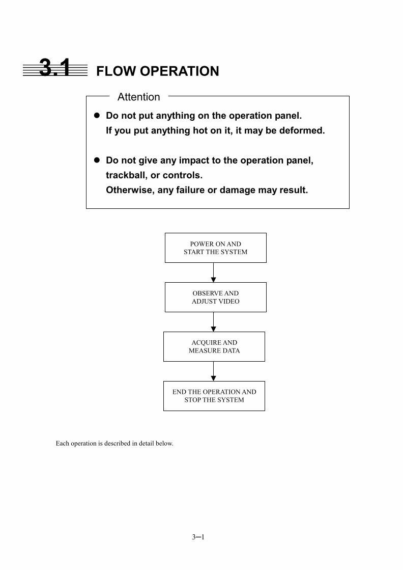
3─1
3.1 FLOW OPERATION
Each operation is described in detail below.
��Do not put anything on the operation panel. If you put anything hot on it, it may be deformed.
��Do not give any impact to the operation panel, trackball, or controls. Otherwise, any failure or damage may result.
Attention
POWER ON AND START THE SYSTEM
OBSERVE AND ADJUST VIDEO
ACQUIRE AND MEASURE DATA
END THE OPERATION AND STOP THE SYSTEM
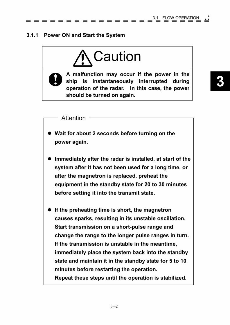
3─2
3
3.1 FLOW OPERATION �
� �
��Wait for about 2 seconds before turning on the
power again.
��Immediately after the radar is installed, at start of the system after it has not been used for a long time, or after the magnetron is replaced, preheat the equipment in the standby state for 20 to 30 minutes before setting it into the transmit state.
��If the preheating time is short, the magnetron causes sparks, resulting in its unstable oscillation. Start transmission on a short-pulse range and change the range to the longer pulse ranges in turn. If the transmission is unstable in the meantime, immediately place the system back into the standby state and maintain it in the standby state for 5 to 10 minutes before restarting the operation. Repeat these steps until the operation is stabilized.
Caution
3.1.1 Power ON and Start the System
Attention
A malfunction may occur if the power in theship is instantaneously interrupted duringoperation of the radar. In this case, the powershould be turned on again.
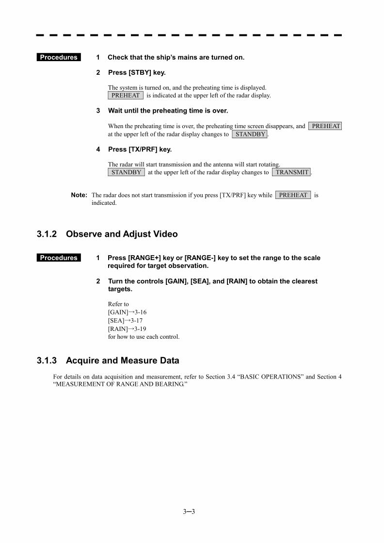
3─3
Procedures 1 Check that the ship’s mains are turned on.
2 Press [STBY] key.
The system is turned on, and the preheating time is displayed. PREHEAT is indicated at the upper left of the radar display.
3 Wait until the preheating time is over.
When the preheating time is over, the preheating time screen disappears, and PREHEAT at the upper left of the radar display changes to STANDBY .
4 Press [TX/PRF] key. The radar will start transmission and the antenna will start rotating. STANDBY at the upper left of the radar display changes to TRANSMIT .
Note: The radar does not start transmission if you press [TX/PRF] key while PREHEAT is indicated.
3.1.2 Observe and Adjust Video
Procedures 1 Press [RANGE+] key or [RANGE-] key to set the range to the scale required for target observation.
2 Turn the controls [GAIN], [SEA], and [RAIN] to obtain the clearest
targets. Refer to [GAIN]→3-16 [SEA]→3-17 [RAIN]→3-19 for how to use each control.
3.1.3 Acquire and Measure Data
For details on data acquisition and measurement, refer to Section 3.4 “BASIC OPERATIONS” and Section 4 “MEASUREMENT OF RANGE AND BEARING.”
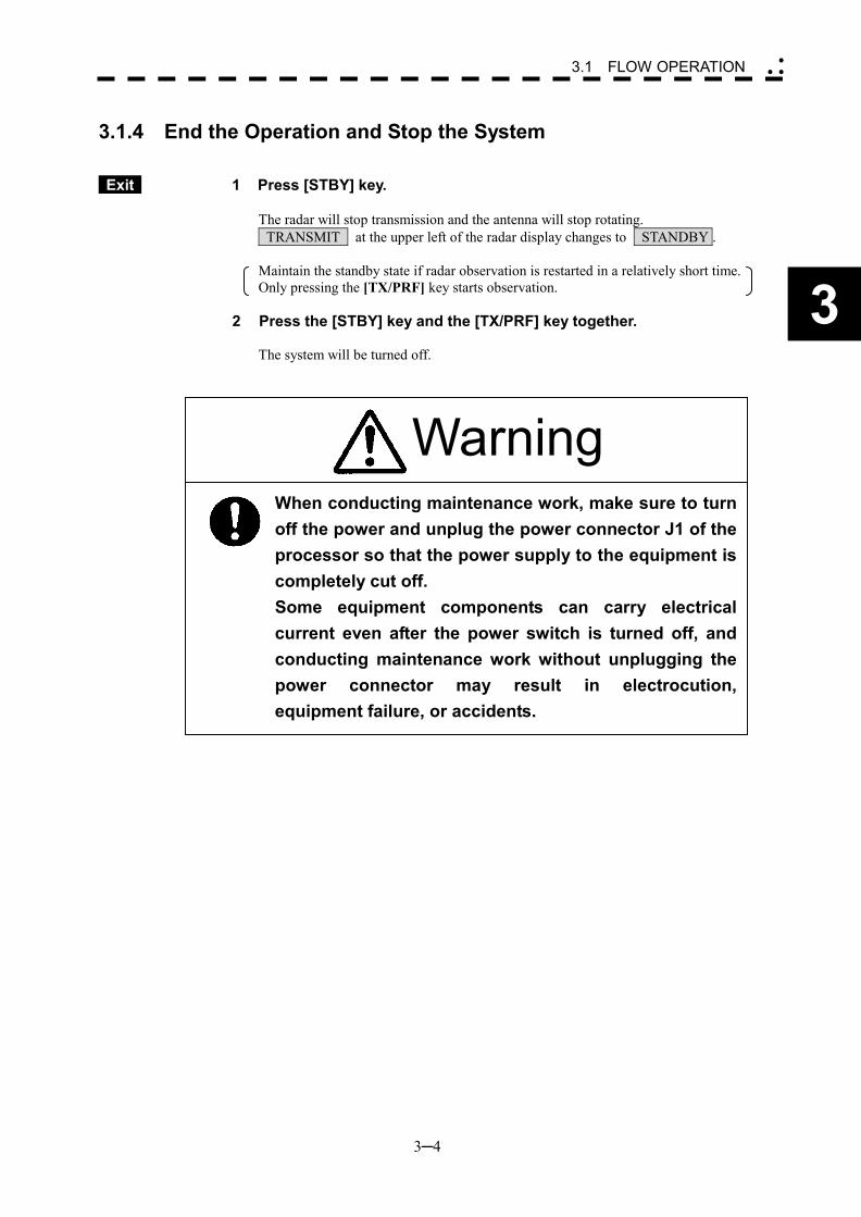
3─4
3
3.1 FLOW OPERATION �
� �
3.1.4 End the Operation and Stop the System
Exit 1 Press [STBY] key.
The radar will stop transmission and the antenna will stop rotating. TRANSMIT at the upper left of the radar display changes to STANDBY . Maintain the standby state if radar observation is restarted in a relatively short time. Only pressing the [TX/PRF] key starts observation.
2 Press the [STBY] key and the [TX/PRF] key together. The system will be turned off.
When conducting maintenance work, make sure to turnoff the power and unplug the power connector J1 of theprocessor so that the power supply to the equipment iscompletely cut off. Some equipment components can carry electricalcurrent even after the power switch is turned off, andconducting maintenance work without unplugging thepower connector may result in electrocution,equipment failure, or accidents.
Warning
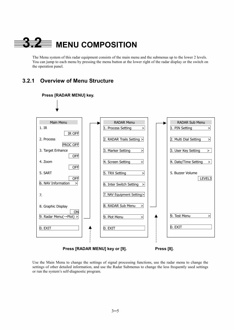
3─5
3.2 MENU COMPOSITION
The Menu system of this radar equipment consists of the main menu and the submenus up to the lower 2 levels. You can jump to each menu by pressing the menu button at the lower right of the radar display or the switch on the operation panel.
3.2.1 Overview of Menu Structure
Press [RADAR MENU] key.
Press [RADAR MENU] key or [9]. Press [8].
Use the Main Menu to change the settings of signal processing functions, use the radar menu to change the settings of other detailed information, and use the Radar Submenus to change the less frequently used settings or run the system’s self-diagnostic program.
Main Menu
1. IR
IR OFF
2. Process
PROC OFF
3. Target Enhance
OFF
4. Zoom
OFF
5. SART
OFF6. NAV Information >
7.
8. Graphic Display
ON9. Radar Menu(→Plot) >
0. EXIT
RADAR Menu
1. Process Setting >
2. RADAR Trails Setting >
3. Marker Setting >
4. Screen Setting >
5. TRX Setting >
6. Inter Switch Setting >
7. NAV Equipment Setting>
8. RADAR Sub Menu >
9. Plot Menu >
0. EXIT
RADAR Sub Menu
1. PIN Setting >
2. Multi Dial Setting >
3. User Key Setting >
4. Date/Time Setting >
5. Buzzer Volume
LEVEL3
9. Test Menu >
0. EXIT
3─6
3
3.2 MENU COMPOSITION �
� �
3.2.2 Basic Menu Operation
To open the menu:
Press [RADAR MENU] key.
To close the menu:
Press [RADAR MENU] key. Alternatively, hold down [0] key until the menu closes. * Button 54 on the radar display on page 2-7 is also available to switch between ON and OFF.
To move to a lower level of the menu:
The menu is in hierarchical structure. Press the numeric keys [1]-[9] corresponding to the desired menu item number. Control will move to the lower level. Alternatively, place the cursor over the item and then press [ENT] key. > is shown at the right end of a menu item having a lower level.
To move to a higher level of the menu:
Press [0] key while the menu is open. Control will return to the higher level from the lower level. Alternatively, place the cursor over the 0.EXIT item and then press [ENT] key.
To determine an item:
Press the numeric keys [1]-[9] corresponding to the desired item number. The selected item will be displayed. Alternatively, place the cursor over the item you want to change, and then press [ENT] key.
To determine the selected item:
Press the numeric keys [1]-[9] corresponding to the selected item number. Alternatively, place the cursor over the selected item and then press [ENT] key. If you do not change the setting of the selected item, press [CLR/INFO] key.
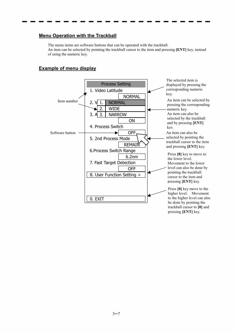
3─7
Menu Operation with the Trackball
The menu items are software buttons that can be operated with the trackball. An item can be selected by pointing the trackball cursor to the item and pressing [ENT] key, instead of using the numeric key.
Example of menu display
Process Setting1. Video Latitude
NORMAL2. VD Noise Rejection
LOW3. Auto DR Control
ON4. Process Switch
OFF5. 2nd Process Mode
REMAIN6.Process Switch Range
6.2nm7. Fast Target Detection
OFF8. User Function Setting >
0. EXIT
NORMAL1.WIDE2.NARROW3.
Item number
Software button
The selected item is displayed by pressing the corresponding numeric key. An item can be selected by pressing the corresponding numeric key. An item can also be selected by the trackball and by pressing [ENT] key.An item can also be selected by pointing the trackball cursor to the item and pressing [ENT] key.
Press [8] key to move to the lower level. Movement to the lower level can also be done by pointing the trackball cursor to the item and pressing [ENT] key.
Press [0] key move to the higher level. Movement to the higher level can alsobe done by pointing the trackball cursor to [0] and pressing [ENT] key.
3─8
3
3.3 PREPARATION
3.3.1 Adjust Display Brilliance
Procedures 1 Obtain the best-to-see display with optimum brilliance by turning the [BRILL] control at the lower right of the display. Turning the [BRILL] control clockwise increases the brilliance of the entire display. Conversely, turning the [BRILL] control counterclockwise decreases the brilliance of the entire display. In consideration of the ambient brightness, adjust display brilliance that is high enough to easily observe the radar display but does not glare.
3.3.2 Adjust Contrast
Adjust the contrast of the radar video display.
Procedures 1 Point the trackball to the VID button at the lower right of the radar display, press [ENT] key, and then make adjustment to obtain the best-to-see video. Point the trackball to the VID button at the lower right of the radar display and then press [ENT] key to adjust the contrast of the radar video display at four levels. Each time the VID button is clicked, the contrast level changes in the following sequence: Adjust the VID button to obtain the best-to-see video with optimum contrast. * Button 61 on the radar display on page 2-7 is also available for switching.
3─9
3.3.3 Adjust Operation Panel Brilliance [PANEL]
Procedures 1 Press [PANEL] key to adjust the brilliance of the operation panel light. There are five brilliance levels, and brilliance increases by one level each time the [PANEL] key is pressed. When it reaches the highest level, it is resumed to the lowest level. In consideration of the ambient brightness, adjust panel brilliance that is high enough to read the characters on the operation panel but does not glare. The [PANEL] key lamp lights up irrespective of panel brilliance adjustment. * Button 60 on the radar display on page 2-7 is also available for switching.
3.3.4 Switch Day/Night Mode [DAY/NIGHT]
The day/night mode changes in the following sequence each time the [DAY/NIGHT] key is pressed: DAY1 � DAY2 � NIGHT1 � NIGHT2
The current mode is indicated at the lower right of the radar display. The brilliance level in accordance with the selected mode is saved. For brilliance adjustment, refer to page 3-12. For day/night mode switching, refer to Section 3.3.8 “Set Display Color.” * Button 63 on the radar display on page 2-7 is also available for switching.
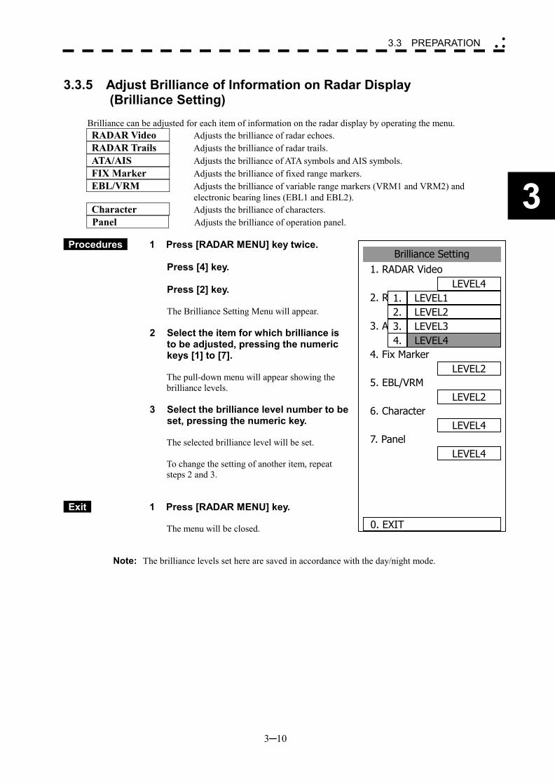
3─10
3
3.3 PREPARATION �
� �
Brilliance Setting1. RADAR Video
LEVEL42. RADAR Trails
LEVEL43. ATA/AIS
LEVEL34. Fix Marker
LEVEL25. EBL/VRM
LEVEL26. Character
LEVEL47. Panel
LEVEL4
0. EXIT
LEVEL11.LEVEL22.LEVEL33.LEVEL44.
3.3.5 Adjust Brilliance of Information on Radar Display (Brilliance Setting)
Brilliance can be adjusted for each item of information on the radar display by operating the menu. RADAR Video Adjusts the brilliance of radar echoes. RADAR Trails Adjusts the brilliance of radar trails. ATA/AIS Adjusts the brilliance of ATA symbols and AIS symbols. FIX Marker Adjusts the brilliance of fixed range markers. EBL/VRM Adjusts the brilliance of variable range markers (VRM1 and VRM2) and
electronic bearing lines (EBL1 and EBL2). Character Adjusts the brilliance of characters. Panel Adjusts the brilliance of operation panel.
Procedures 1 Press [RADAR MENU] key twice.
Press [4] key. Press [2] key.
The Brilliance Setting Menu will appear.
2 Select the item for which brilliance is to be adjusted, pressing the numeric keys [1] to [7]. The pull-down menu will appear showing the brilliance levels.
3 Select the brilliance level number to be set, pressing the numeric key. The selected brilliance level will be set. To change the setting of another item, repeat steps 2 and 3.
Exit 1 Press [RADAR MENU] key. The menu will be closed.
Note: The brilliance levels set here are saved in accordance with the day/night mode.
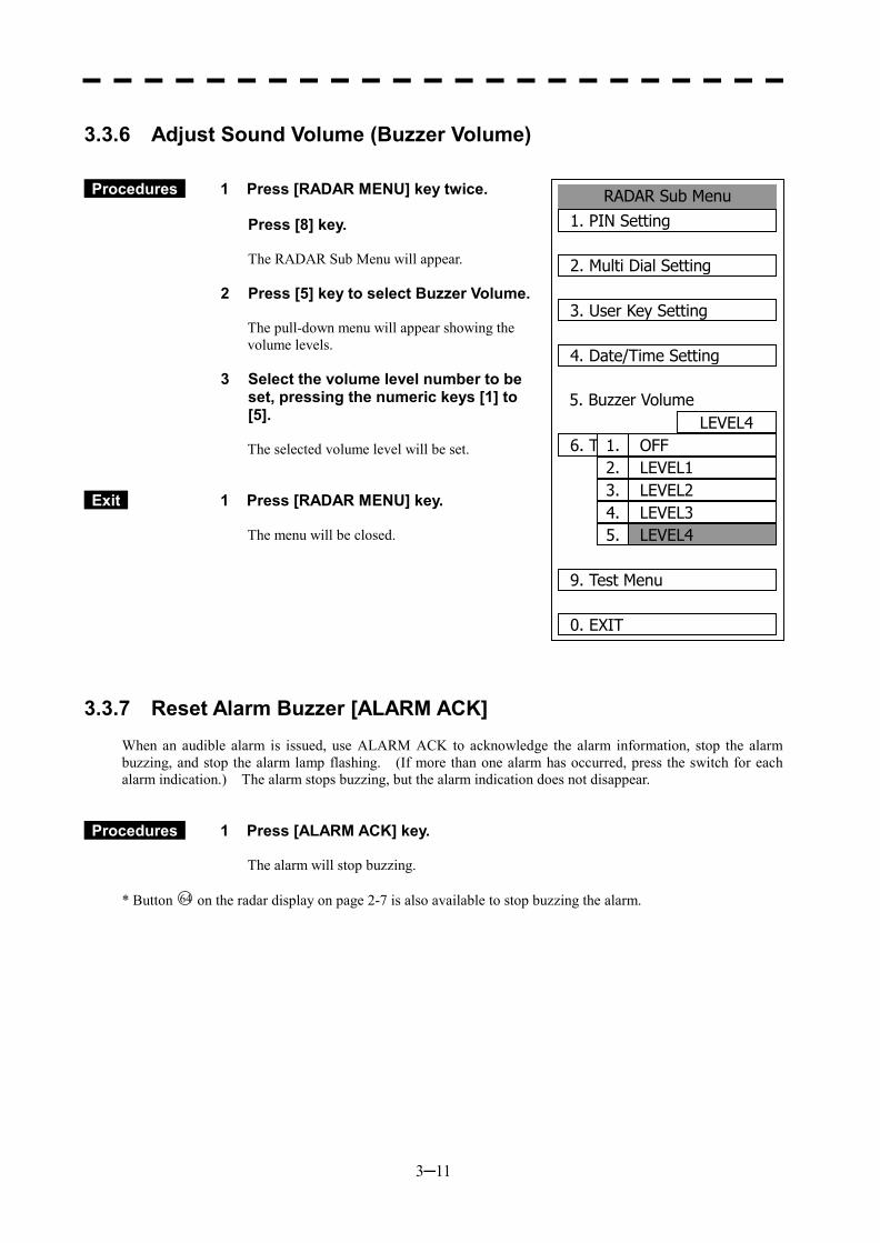
3─11
3.3.6 Adjust Sound Volume (Buzzer Volume)
Procedures 1 Press [RADAR MENU] key twice. Press [8] key.
The RADAR Sub Menu will appear.
2 Press [5] key to select Buzzer Volume. The pull-down menu will appear showing the volume levels.
3 Select the volume level number to be set, pressing the numeric keys [1] to [5]. The selected volume level will be set.
Exit 1 Press [RADAR MENU] key. The menu will be closed.
3.3.7 Reset Alarm Buzzer [ALARM ACK]
When an audible alarm is issued, use ALARM ACK to acknowledge the alarm information, stop the alarm buzzing, and stop the alarm lamp flashing. (If more than one alarm has occurred, press the switch for each alarm indication.) The alarm stops buzzing, but the alarm indication does not disappear.
Procedures 1 Press [ALARM ACK] key. The alarm will stop buzzing.
* Button 64 on the radar display on page 2-7 is also available to stop buzzing the alarm.
RADAR Sub Menu1. PIN Setting
2. Multi Dial Setting
3. User Key Setting
4. Date/Time Setting
5. Buzzer VolumeLEVEL4
6. TEST MENU
9. Test Menu
0. EXIT
LEVEL4
1. OFF
5.
2. LEVEL13. LEVEL24. LEVEL3
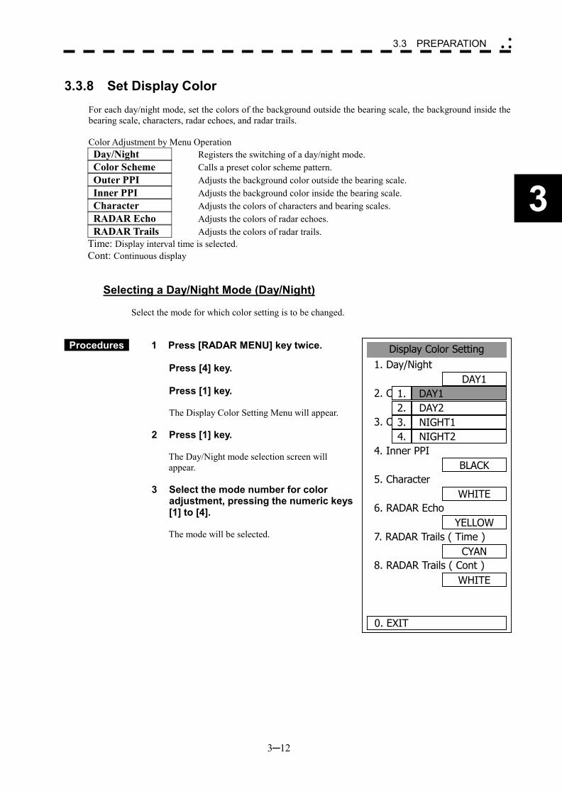
3─12
3
3.3 PREPARATION �
� �
3.3.8 Set Display Color
For each day/night mode, set the colors of the background outside the bearing scale, the background inside the bearing scale, characters, radar echoes, and radar trails. Color Adjustment by Menu Operation Day/Night Registers the switching of a day/night mode. Color Scheme Calls a preset color scheme pattern. Outer PPI Adjusts the background color outside the bearing scale. Inner PPI Adjusts the background color inside the bearing scale. Character Adjusts the colors of characters and bearing scales. RADAR Echo Adjusts the colors of radar echoes. RADAR Trails Adjusts the colors of radar trails. Time: Display interval time is selected. Cont: Continuous display
Selecting a Day/Night Mode (Day/Night)
Select the mode for which color setting is to be changed.
Procedures 1 Press [RADAR MENU] key twice. Press [4] key. Press [1] key.
The Display Color Setting Menu will appear.
2 Press [1] key.
The Day/Night mode selection screen will appear.
3 Select the mode number for color adjustment, pressing the numeric keys [1] to [4]. The mode will be selected.
Display Color Setting1. Day/Night
DAY12. Color Scheme
ORIGINAL3. Outer PPI
GRAY4. Inner PPI
BLACK5. Character
WHITE6. RADAR Echo
YELLOW7. RADAR Trails ( Time )
CYAN8. RADAR Trails ( Cont )
WHITE
0. EXIT
DAY11.DAY22.NIGHT13.NIGHT24.
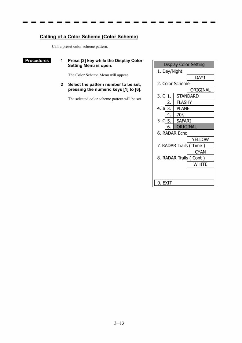
3─13
Calling of a Color Scheme (Color Scheme)
Call a preset color scheme pattern.
Procedures 1 Press [2] key while the Display Color Setting Menu is open. The Color Scheme Menu will appear.
2 Select the pattern number to be set, pressing the numeric keys [1] to [6]. The selected color scheme pattern will be set.
Display Color Setting1. Day/Night
DAY12. Color Scheme
ORIGINAL3. Outer PPI
GRAY4. Inner PPI
BLACK5. Character
WHITE6. RADAR Echo
YELLOW7. RADAR Trails ( Time )
CYAN8. RADAR Trails ( Cont )
WHITE
0. EXIT
STANDARD1.FLASHY2.PLANE3.70’s4.SAFARI5.ORIGINAL6.
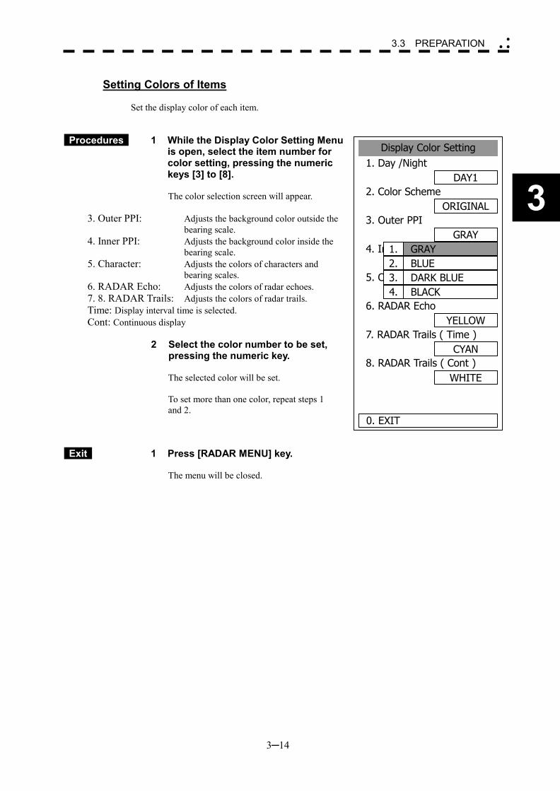
3─14
3
3.3 PREPARATION �
� �
Setting Colors of Items
Set the display color of each item.
Procedures 1 While the Display Color Setting Menu is open, select the item number for color setting, pressing the numeric keys [3] to [8]. The color selection screen will appear.
3. Outer PPI: Adjusts the background color outside the bearing scale.
4. Inner PPI: Adjusts the background color inside the bearing scale.
5. Character: Adjusts the colors of characters and bearing scales.
6. RADAR Echo: Adjusts the colors of radar echoes. 7. 8. RADAR Trails: Adjusts the colors of radar trails. Time: Display interval time is selected. Cont: Continuous display
2 Select the color number to be set,
pressing the numeric key. The selected color will be set. To set more than one color, repeat steps 1 and 2.
Exit 1 Press [RADAR MENU] key. The menu will be closed.
Display Color Setting1. Day /Night
DAY12. Color Scheme
ORIGINAL3. Outer PPI
GRAY4. Inner PPI
BLACK5. Character
WHITE6. RADAR Echo
YELLOW7. RADAR Trails ( Time )
CYAN8. RADAR Trails ( Cont )
WHITE
0. EXIT
1.BLUE2.DARK BLUE3.BLACK4.
GRAY
3─15
3.4 BASIC OPERATIONS 3.4.1 Start Transmission [TX/PRF]
Procedures 1 Press [TX/PRF] key. The radar will start transmission and the antenna will start rotating. The indication STANDBY at the upper left of the radar display changes to TRANSMIT .
Note: The radar does not start transmission if you press [TX/PRF] key while PREHEAT is indicated.
3.4.2 Stop Transmission [STBY]
Procedures 1 Press [STBY] key. The radar will stop transmission and the antenna will stop rotating. The indication TRANSMIT at the upper left of the radar display changes to STANDBY .
* Button 6 on the radar display on page 2-7 is also available to start/stop transmission.
3.4.3 Change Range (Observation Range Scale) [RANGE+/-]
Procedures 1 Press [RANGE+] key or [RANGE-] key to set the range to the scale required for target observation. To observe long-range targets, press [RANGE+] key. To zoom and observe a short-range target near the own ship, press [RANGE-] key.
* Button 1 on the radar display on page 2-7 is also available to switch the range.
3─16
3
3.4 BASIC OPERATIONS �
� �
3.4.4 Tune
This system tunes the transmitting frequency and receiving frequency under automatic control, so it does not need any tuning by hand
3.4.5 Control Sensitivity [GAIN/PL]
Procedures 1 Control noise on the radar display by turning the [GAIN/PL] control until targets can be easily observed. Turning [GAIN/PL] control clockwise increases sensitivity. Turning [GAIN/PL] control counterclockwise decreases sensitivity.
Turning the [GAIN/PL] control clockwise increases receiving sensitivity and extends the radar observation range. If the sensitivity is too high, the receiver noise increases reducing the contrast between the targets and the background video. As a result, the targets become obscure on the radar display. To observe densely crowded targets or short-range targets, turn the [GAIN/PL] control counterclockwise to reduce the sensitivity so that the targets are easy to observe. However, be careful not to overlook important small targets.
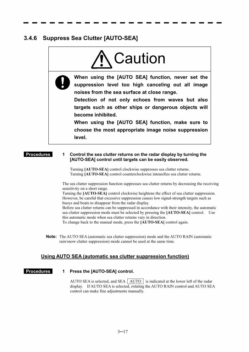
3─17
3.4.6 Suppress Sea Clutter [AUTO-SEA]
Procedures 1 Control the sea clutter returns on the radar display by turning the [AUTO-SEA] control until targets can be easily observed. Turning [AUTO-SEA] control clockwise suppresses sea clutter returns. Turning [AUTO-SEA] control counterclockwise intensifies sea clutter returns.
The sea clutter suppression function suppresses sea clutter returns by decreasing the receiving sensitivity on a short range. Turning the [AUTO-SEA] control clockwise heightens the effect of sea clutter suppression. However, be careful that excessive suppression causes low signal-strength targets such as buoys and boats to disappear from the radar display. Before sea clutter returns can be suppressed in accordance with their intensity, the automatic sea clutter suppression mode must be selected by pressing the [AUTO-SEA] control. Use this automatic mode when sea clutter returns vary in direction. To change back to the manual mode, press the [AUTO-SEA] control again.
Note: The AUTO SEA (automatic sea clutter suppression) mode and the AUTO RAIN (automatic rain/snow clutter suppression) mode cannot be used at the same time.
Using AUTO SEA (automatic sea clutter suppression function)
Procedures 1 Press the [AUTO-SEA] control. AUTO SEA is selected, and SEA AUTO is indicated at the lower left of the radar display. If AUTO SEA is selected, rotating the AUTO RAIN control and AUTO SEA control can make fine adjustments manually.
When using the [AUTO SEA] function, never set the suppression level too high canceling out all imagenoises from the sea surface at close range. Detection of not only echoes from waves but alsotargets such as other ships or dangerous objects willbecome inhibited. When using the [AUTO SEA] function, make sure tochoose the most appropriate image noise suppressionlevel.
Caution

3─18
3
3.4 BASIC OPERATIONS �
� �
Note: When AUTO SEA is selected, AUTO RAIN is switched to the manual mode. AUTO SEA and AUTO RAIN cannot be selected at the same time.
Cancellation 1 Press the [AUTO-SEA] control. AUTO SEA is deselected, SEA AUTO at the lower left of the radar display changes to SEA MAN , and AUTO SEA is cancelled.
* Button 14 on the radar display on page 2-7 is also available to switch AUTO/MANUAL.
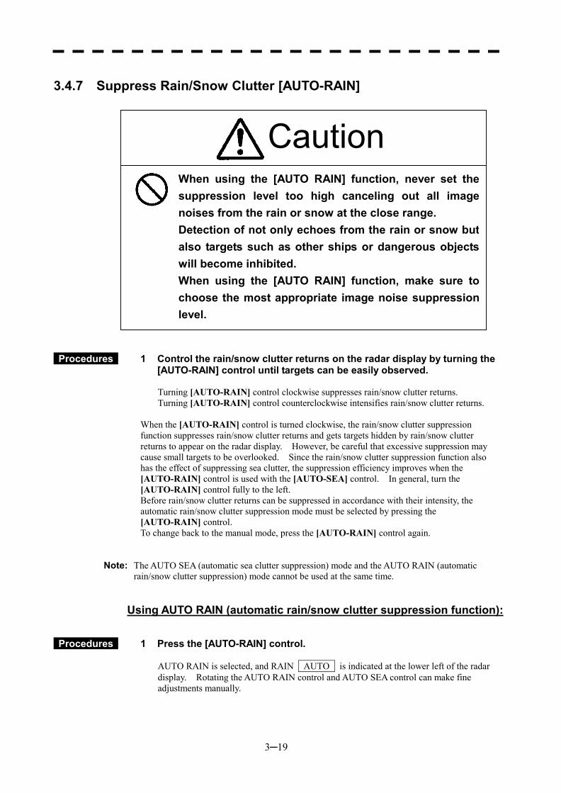
3─19
3.4.7 Suppress Rain/Snow Clutter [AUTO-RAIN]
Procedures 1 Control the rain/snow clutter returns on the radar display by turning the [AUTO-RAIN] control until targets can be easily observed. Turning [AUTO-RAIN] control clockwise suppresses rain/snow clutter returns. Turning [AUTO-RAIN] control counterclockwise intensifies rain/snow clutter returns.
When the [AUTO-RAIN] control is turned clockwise, the rain/snow clutter suppression function suppresses rain/snow clutter returns and gets targets hidden by rain/snow clutter returns to appear on the radar display. However, be careful that excessive suppression may cause small targets to be overlooked. Since the rain/snow clutter suppression function also has the effect of suppressing sea clutter, the suppression efficiency improves when the [AUTO-RAIN] control is used with the [AUTO-SEA] control. In general, turn the [AUTO-RAIN] control fully to the left. Before rain/snow clutter returns can be suppressed in accordance with their intensity, the automatic rain/snow clutter suppression mode must be selected by pressing the [AUTO-RAIN] control. To change back to the manual mode, press the [AUTO-RAIN] control again.
Note: The AUTO SEA (automatic sea clutter suppression) mode and the AUTO RAIN (automatic rain/snow clutter suppression) mode cannot be used at the same time.
Using AUTO RAIN (automatic rain/snow clutter suppression function):
Procedures 1 Press the [AUTO-RAIN] control. AUTO RAIN is selected, and RAIN AUTO is indicated at the lower left of the radar display. Rotating the AUTO RAIN control and AUTO SEA control can make fine adjustments manually.
When using the [AUTO RAIN] function, never set thesuppression level too high canceling out all imagenoises from the rain or snow at the close range. Detection of not only echoes from the rain or snow butalso targets such as other ships or dangerous objectswill become inhibited. When using the [AUTO RAIN] function, make sure tochoose the most appropriate image noise suppressionlevel.
Caution

3─20
3
3.4 BASIC OPERATIONS �
� �
Note: When AUTO RAIN is selected, AUTO SEA is switched to the manual mode. AUTO SEA and AUTO RAIN cannot be selected at the same time.
Cancellation 1 Press the [AUTO-RAIN] control. AUTO RAIN is deselected, RAIN AUTO at the lower left of the radar display changes to RAIN MAN , and AUTO RAIN is cancelled.
* Button 15 on the radar display on page 2-7 is also available to switch AUTO/MANUAL.
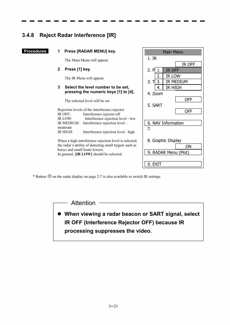
3─21
3.4.8 Reject Radar Interference [IR]
Procedures 1 Press [RADAR MENU] key. The Main Menu will appear.
2 Press [1] key. The IR Menu will appear.
3 Select the level number to be set, pressing the numeric keys [1] to [4]. The selected level will be set.
Rejection levels of the interference rejector IR OFF: Interference rejector off IR LOW: Interference rejection level - low IR MEDIUM: Interference rejection level - moderate IR HIGH: Interference rejection level - high When a high interference rejection level is selected, the radar’s ability of detecting small targets such as buoys and small boats lowers. In general, [IR LOW] should be selected.
* Button 10 on the radar display on page 2-7 is also available to switch IR settings.
��When viewing a radar beacon or SART signal, select IR OFF (Interference Rejector OFF) because IR processing suppresses the video.
Attention
Main Menu1. IR
IR OFF2. PROCES
PROC OFF3. TARGET ENHANCE
OFF4. Zoom
OFF5. SART
OFF 6. NAV Information7.
8. Graphic DisplayON
9. RADAR Menu (Plot)
0. EXIT
IR OFF1.IR LOW2.IR MEDIUM3.IR HIGH4.
3─22
3
3.4 BASIC OPERATIONS �
� �
3.4.9 Hide/Display Range Rings (RINGS)
Procedures 1 Press [RR/HL] key. The range rings display switches back and forth between display and non-display each time [RR/HL] key is pressed. Refer to page 3-10 for how to change the brilliance of range rings.
* Button 2 on the radar display on page 2-7 is also available to switch between ON and OFF.
3.4.10 Hide Ship’s Heading Line (HL OFF)
Procedures 1 Hold down [RR/HL] key. The ship’s heading line is hidden while [RR/HL] key is held down.
The ship’s heading line (HL) that presents the course of own ship is always shown on the radar display. The heading line is hidden while [RR/HL] key is held down, so the targets on the heading line can be easily observed.
* Button 22 on the radar display on page 2-7 is also available to switch between ON and OFF.
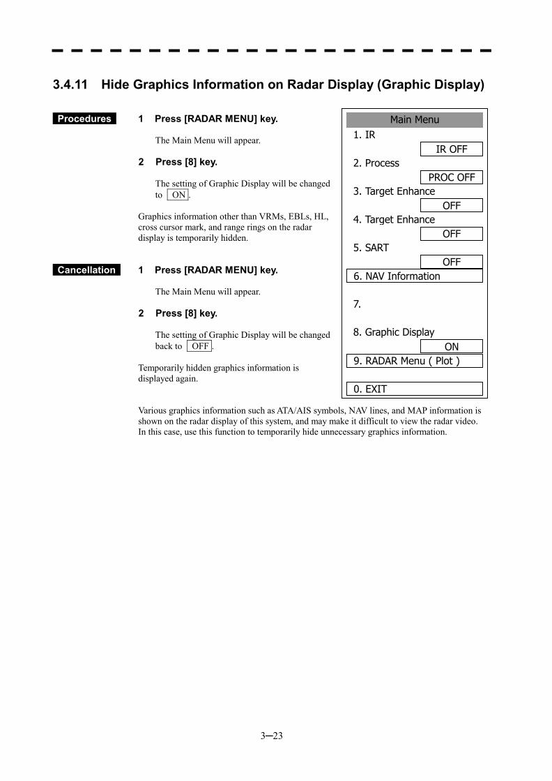
3─23
Main Menu1. IR
IR OFF2. Process
PROC OFF3. Target Enhance
OFF4. Target Enhance
OFF5. SART
OFF6. NAV Information
7.
8. Graphic DisplayON
9. RADAR Menu ( Plot )
0. EXIT
3.4.11 Hide Graphics Information on Radar Display (Graphic Display)
Procedures 1 Press [RADAR MENU] key. The Main Menu will appear.
2 Press [8] key. The setting of Graphic Display will be changed to ON .
Graphics information other than VRMs, EBLs, HL, cross cursor mark, and range rings on the radar display is temporarily hidden.
Cancellation 1 Press [RADAR MENU] key. The Main Menu will appear.
2 Press [8] key. The setting of Graphic Display will be changed back to OFF .
Temporarily hidden graphics information is displayed again. Various graphics information such as ATA/AIS symbols, NAV lines, and MAP information is shown on the radar display of this system, and may make it difficult to view the radar video. In this case, use this function to temporarily hide unnecessary graphics information.
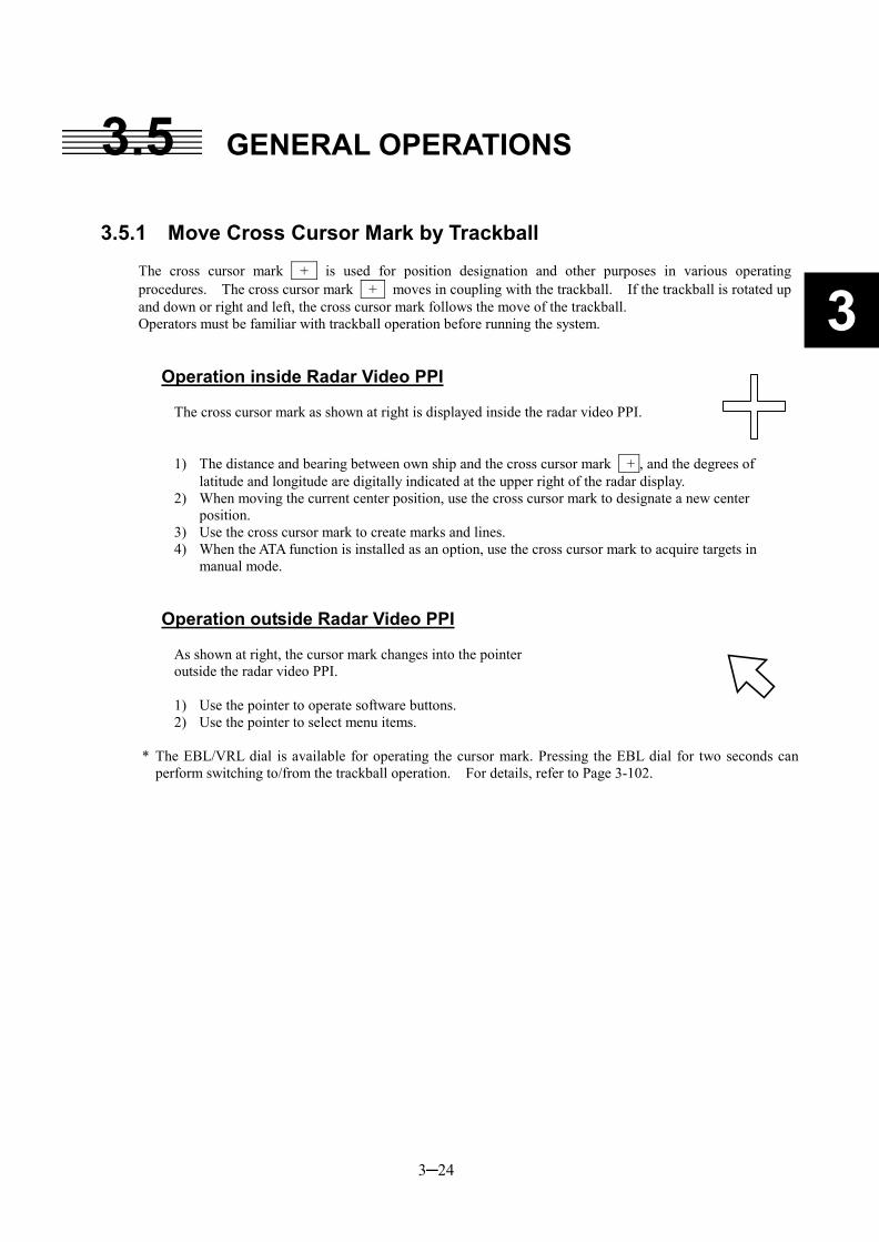
3─24
3
3.5 GENERAL OPERATIONS 3.5.1 Move Cross Cursor Mark by Trackball
The cross cursor mark + is used for position designation and other purposes in various operating procedures. The cross cursor mark + moves in coupling with the trackball. If the trackball is rotated up and down or right and left, the cross cursor mark follows the move of the trackball. Operators must be familiar with trackball operation before running the system.
Operation inside Radar Video PPI
The cross cursor mark as shown at right is displayed inside the radar video PPI.
1) The distance and bearing between own ship and the cross cursor mark + , and the degrees of latitude and longitude are digitally indicated at the upper right of the radar display.
2) When moving the current center position, use the cross cursor mark to designate a new center position.
3) Use the cross cursor mark to create marks and lines. 4) When the ATA function is installed as an option, use the cross cursor mark to acquire targets in
manual mode.
Operation outside Radar Video PPI
As shown at right, the cursor mark changes into the pointer outside the radar video PPI. 1) Use the pointer to operate software buttons. 2) Use the pointer to select menu items.
* The EBL/VRL dial is available for operating the cursor mark. Pressing the EBL dial for two seconds can
perform switching to/from the trackball operation. For details, refer to Page 3-102.
3─25
3.5.2 Use EBLs (Electronic Bearing Lines) [EBL1/2]
EBLs (Electronic Bearing Lines) are indispensable to the measurement of bearings. Operators must be familiar with the operation of EBLs beforehand.
EBL1 Operation
If EBL2 is selected or EBL1 is not displayed, press [EBL1] key to select EBL1 before starting operation. (The currently selected EBL is shown in reverse video at the lower right of the radar display.)
Procedures 1 Press [EBL1] key. EBL1 at the lower right of the radar display will be shown in reverse video, and EBL1 becomes operable.
2 Press [EBL1] key again. The EBL1 display will disappear.
* Button 31 on the radar display on page 2-7 is also available to switch EBL1 between ON and OFF.
EBL2 Operation
If EBL1 is selected or EBL2 is not displayed, press [EBL2] key to select EBL2 before starting operation. (The currently selected EBL is shown in reverse video at the lower right of the radar display.)
Procedures 1 Press [EBL2] key. EBL2 at the lower right of the radar display will be shown in reverse video, and EBL2 becomes operable.
2 Press [EBL2] key again. The EBL2 display will disappear.
* Button 32 on the radar display on page 2-7 is also available to switch EBL1 between ON and OFF.
Operation procedures are described on the following pages. For how to measure distance and bearing, see Section 4.
3─26
3
3.5 BASIC OPERATIONS �
� �
EBL Bearing Display
The bearing values of EBL1 and EBL2 currently displayed on the PPI are indicated at the lower right of the radar display. The currently operable EBL1 or EBL2 is shown in reverse video beside the bearing value.
Starting Point of EBL
The starting point of the currently operating EBL can be switched from the center of the radar display (CENTER) to any offset position (OFFSET).
Note: The offset position of the EBL’s starting point can be fixed on the radar display or at specific latitude and longitude. (For details, refer to page 3-28.)
[I] Offsetting the starting point of EBL1 while EBL1 is operating:
Procedures 1 Press the [EBL] control. The indication C to the right of the EBL value at the lower right of the radar display will change to O , and “OFFSET” will be set.
* Button 35 on the radar display on page 2-7 is also available to switch the offset of EBL1. * Button 36 on the radar display on page 2-7 is also available to switch the offset of EBL2.
2 Move the starting point of EBL1 with the trackball.
3 Press [ENT] key at the starting point of EBL1 you want to move.
The starting point of EBL1 will be determined.
If EBL2 is operating, the starting point of EBL2 is offset.
[II] Moving the starting point of EBL1 to the own ship’s position while EBL1 is operating:
Procedures 1 Press the [EBL] control twice.
The indication O to the right of the EBL value at the lower right of the radar display will change to C , and “CENTER” will be set.
* Button 35 on the radar display on page 2-7 is also available to switch EBL1 CENTER. * Button 36 on the radar display on page 2-7 is also available to switch EBL2 CENTER.
If EBL2 is operating, the starting point of EBL2 moves to the own ship’s position.
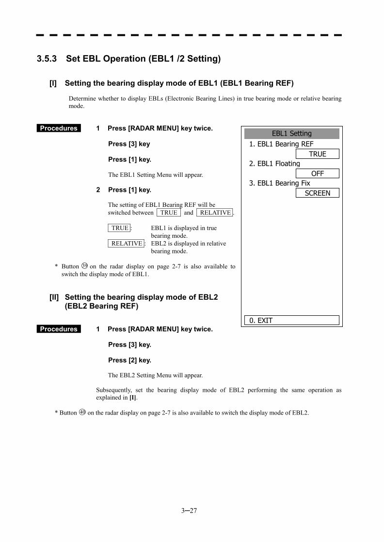
3─27
3.5.3 Set EBL Operation (EBL1 /2 Setting)
[I] Setting the bearing display mode of EBL1 (EBL1 Bearing REF)
Determine whether to display EBLs (Electronic Bearing Lines) in true bearing mode or relative bearing mode.
Procedures 1 Press [RADAR MENU] key twice. Press [3] key Press [1] key.
The EBL1 Setting Menu will appear.
2 Press [1] key. The setting of EBL1 Bearing REF will be switched between TRUE and RELATIVE . TRUE : EBL1 is displayed in true
bearing mode. RELATIVE : EBL2 is displayed in relative
bearing mode.
* Button 39 on the radar display on page 2-7 is also available to switch the display mode of EBL1.
[II] Setting the bearing display mode of EBL2 (EBL2 Bearing REF)
Procedures 1 Press [RADAR MENU] key twice. Press [3] key. Press [2] key.
The EBL2 Setting Menu will appear.
Subsequently, set the bearing display mode of EBL2 performing the same operation as explained in [I].
* Button 40 on the radar display on page 2-7 is also available to switch the display mode of EBL2.
EBL1 Setting1. EBL1 Bearing REF
TRUE2. EBL1 Floating
OFF3. EBL1 Bearing Fix
SCREEN
0. EXIT
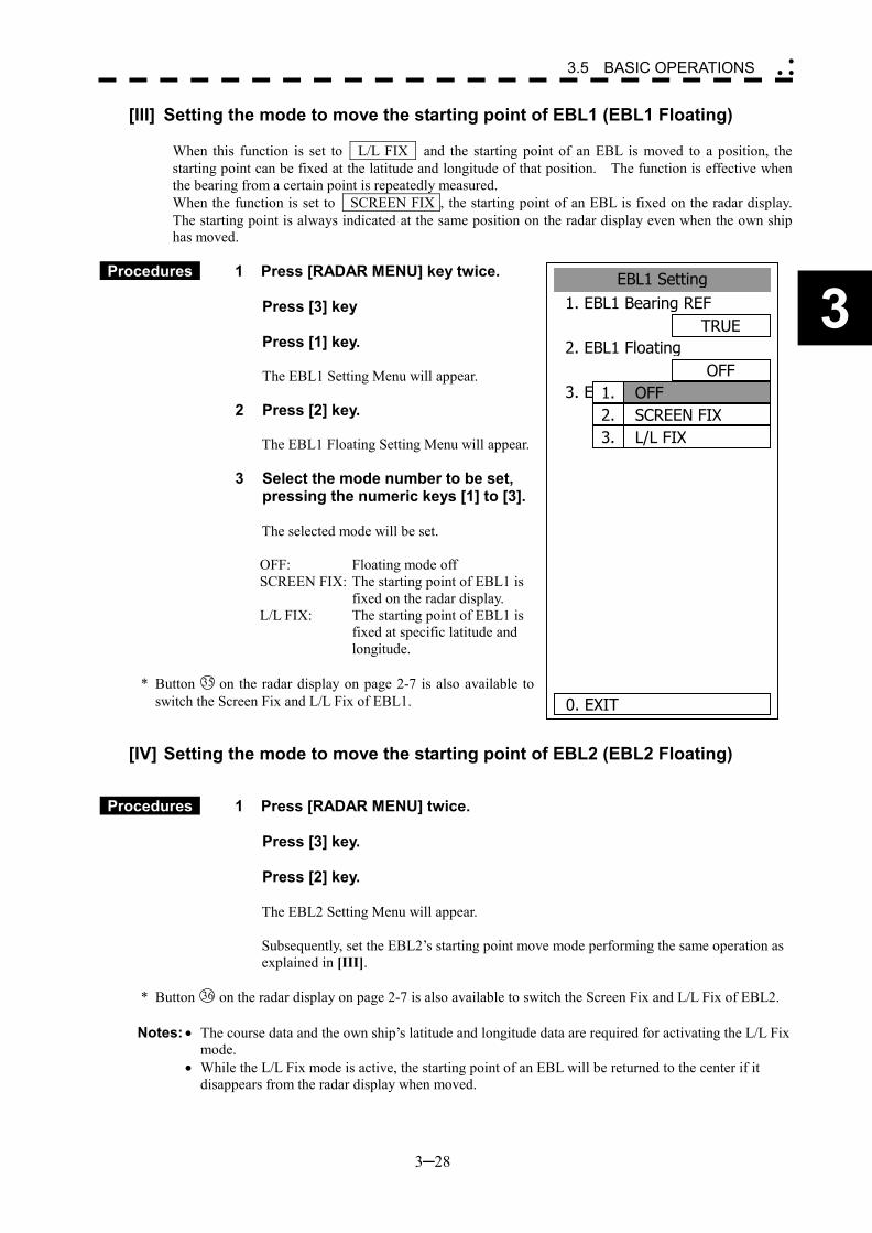
3─28
3
3.5 BASIC OPERATIONS �
� �
[III] Setting the mode to move the starting point of EBL1 (EBL1 Floating)
When this function is set to L/L FIX and the starting point of an EBL is moved to a position, the starting point can be fixed at the latitude and longitude of that position. The function is effective when the bearing from a certain point is repeatedly measured. When the function is set to SCREEN FIX , the starting point of an EBL is fixed on the radar display. The starting point is always indicated at the same position on the radar display even when the own ship has moved.
Procedures 1 Press [RADAR MENU] key twice.
Press [3] key Press [1] key.
The EBL1 Setting Menu will appear.
2 Press [2] key.
The EBL1 Floating Setting Menu will appear.
3 Select the mode number to be set, pressing the numeric keys [1] to [3].
The selected mode will be set. OFF: Floating mode off SCREEN FIX: The starting point of EBL1 is
fixed on the radar display. L/L FIX: The starting point of EBL1 is
fixed at specific latitude and longitude.
* Button 35 on the radar display on page 2-7 is also available to
switch the Screen Fix and L/L Fix of EBL1.
[IV] Setting the mode to move the starting point of EBL2 (EBL2 Floating)
Procedures 1 Press [RADAR MENU] twice. Press [3] key. Press [2] key.
The EBL2 Setting Menu will appear. Subsequently, set the EBL2’s starting point move mode performing the same operation as explained in [III].
* Button 36 on the radar display on page 2-7 is also available to switch the Screen Fix and L/L Fix of EBL2.
Notes: � The course data and the own ship’s latitude and longitude data are required for activating the L/L Fix
mode. � While the L/L Fix mode is active, the starting point of an EBL will be returned to the center if it
disappears from the radar display when moved.
EBL1 Setting1. EBL1 Bearing REF
TRUE2. EBL1 Floating
OFF3. EBL1 Bearing Fix
SCREEN
0. EXIT
OFF1.SCREEN FIX2.
3. L/L FIX
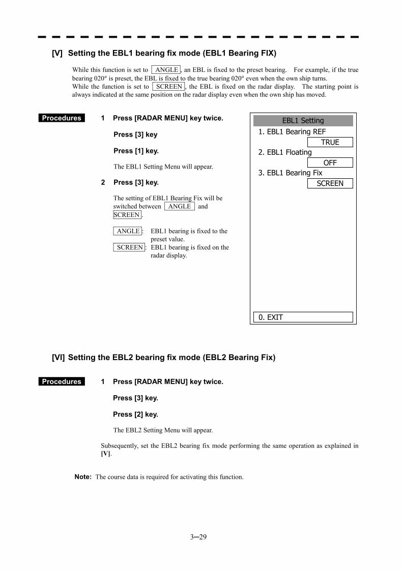
3─29
[V] Setting the EBL1 bearing fix mode (EBL1 Bearing FIX)
While this function is set to ANGLE , an EBL is fixed to the preset bearing. For example, if the true bearing 020� is preset, the EBL is fixed to the true bearing 020� even when the own ship turns. While the function is set to SCREEN , the EBL is fixed on the radar display. The starting point is always indicated at the same position on the radar display even when the own ship has moved.
Procedures 1 Press [RADAR MENU] key twice. Press [3] key Press [1] key.
The EBL1 Setting Menu will appear.
2 Press [3] key.
The setting of EBL1 Bearing Fix will be switched between ANGLE and SCREEN . ANGLE : EBL1 bearing is fixed to the
preset value. SCREEN : EBL1 bearing is fixed on the
radar display.
[VI] Setting the EBL2 bearing fix mode (EBL2 Bearing Fix)
Procedures 1 Press [RADAR MENU] key twice. Press [3] key. Press [2] key.
The EBL2 Setting Menu will appear.
Subsequently, set the EBL2 bearing fix mode performing the same operation as explained in [V].
Note: The course data is required for activating this function.
EBL1 Setting1. EBL1 Bearing REF
TRUE2. EBL1 Floating
OFF3. EBL1 Bearing Fix
SCREEN
0. EXIT
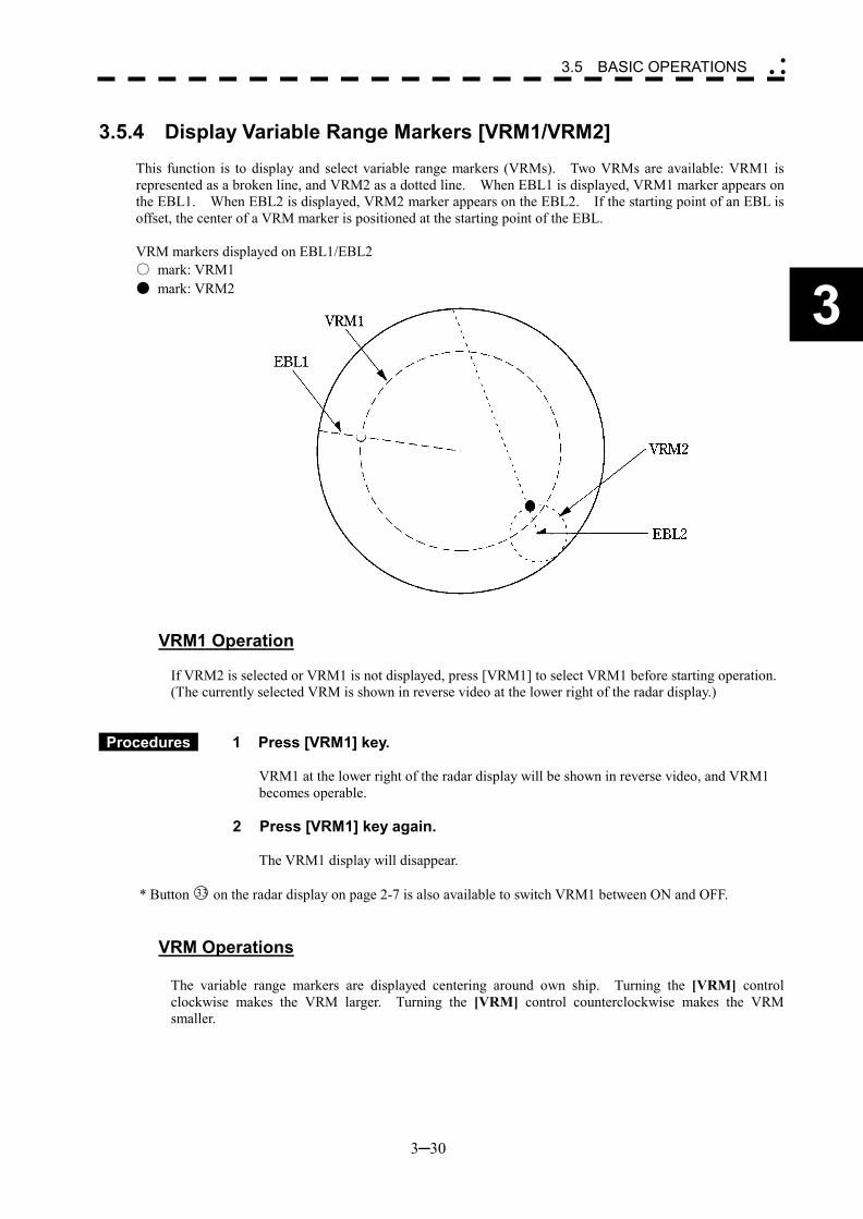
3─30
3
3.5 BASIC OPERATIONS �
� �
3.5.4 Display Variable Range Markers [VRM1/VRM2]
This function is to display and select variable range markers (VRMs). Two VRMs are available: VRM1 is represented as a broken line, and VRM2 as a dotted line. When EBL1 is displayed, VRM1 marker appears on the EBL1. When EBL2 is displayed, VRM2 marker appears on the EBL2. If the starting point of an EBL is offset, the center of a VRM marker is positioned at the starting point of the EBL.
VRM markers displayed on EBL1/EBL2 ○ mark: VRM1 ● mark: VRM2
VRM1 Operation
If VRM2 is selected or VRM1 is not displayed, press [VRM1] to select VRM1 before starting operation. (The currently selected VRM is shown in reverse video at the lower right of the radar display.)
Procedures 1 Press [VRM1] key. VRM1 at the lower right of the radar display will be shown in reverse video, and VRM1 becomes operable.
2 Press [VRM1] key again. The VRM1 display will disappear.
* Button 33 on the radar display on page 2-7 is also available to switch VRM1 between ON and OFF.
VRM Operations
The variable range markers are displayed centering around own ship. Turning the [VRM] control clockwise makes the VRM larger. Turning the [VRM] control counterclockwise makes the VRM smaller.
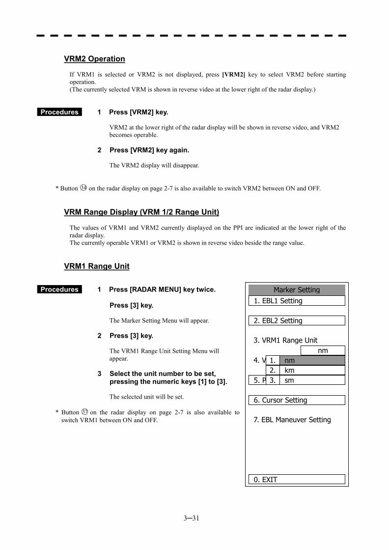
3─31
VRM2 Operation
If VRM1 is selected or VRM2 is not displayed, press [VRM2] key to select VRM2 before starting operation. (The currently selected VRM is shown in reverse video at the lower right of the radar display.)
Procedures 1 Press [VRM2] key. VRM2 at the lower right of the radar display will be shown in reverse video, and VRM2 becomes operable.
2 Press [VRM2] key again. The VRM2 display will disappear.
* Button 34 on the radar display on page 2-7 is also available to switch VRM2 between ON and OFF.
VRM Range Display (VRM 1/2 Range Unit)
The values of VRM1 and VRM2 currently displayed on the PPI are indicated at the lower right of the radar display. The currently operable VRM1 or VRM2 is shown in reverse video beside the range value.
VRM1 Range Unit
Procedures 1 Press [RADAR MENU] key twice. Press [3] key.
The Marker Setting Menu will appear.
2 Press [3] key. The VRM1 Range Unit Setting Menu will appear.
3 Select the unit number to be set, pressing the numeric keys [1] to [3]. The selected unit will be set.
* Button 37 on the radar display on page 2-7 is also available to switch VRM1 between ON and OFF.
2.
Marker Setting1. EBL1 Setting
2. EBL2 Setting
3. VRM1 Range Unitnm
4. VRM2 Range Unitnm
5. Parallel Index Line
6. Cursor Setting
7. EBL Maneuver Setting
0. EXIT
nm1.kmsm3.
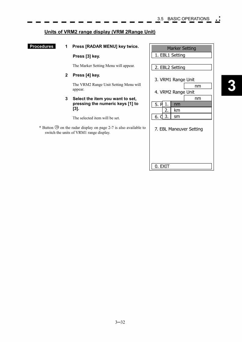
3─32
3
3.5 BASIC OPERATIONS �
� �
Units of VRM2 range display (VRM 2Range Unit)
Procedures 1 Press [RADAR MENU] key twice. Press [3] key.
The Marker Setting Menu will appear.
2 Press [4] key. The VRM2 Range Unit Setting Menu will appear.
3 Select the item you want to set,
pressing the numeric keys [1] to [3].
The selected item will be set.
* Button 38 on the radar display on page 2-7 is also available to
switch the units of VRM1 range display.
2.
Marker Setting1. EBL1 Setting
2. EBL2 Setting
3. VRM1 Range Unitnm
4. VRM2 Range Unitnm
5. Parallel Index Line
6. Cursor Setting
7. EBL Maneuver Setting
0. EXIT
nm1.kmsm3.
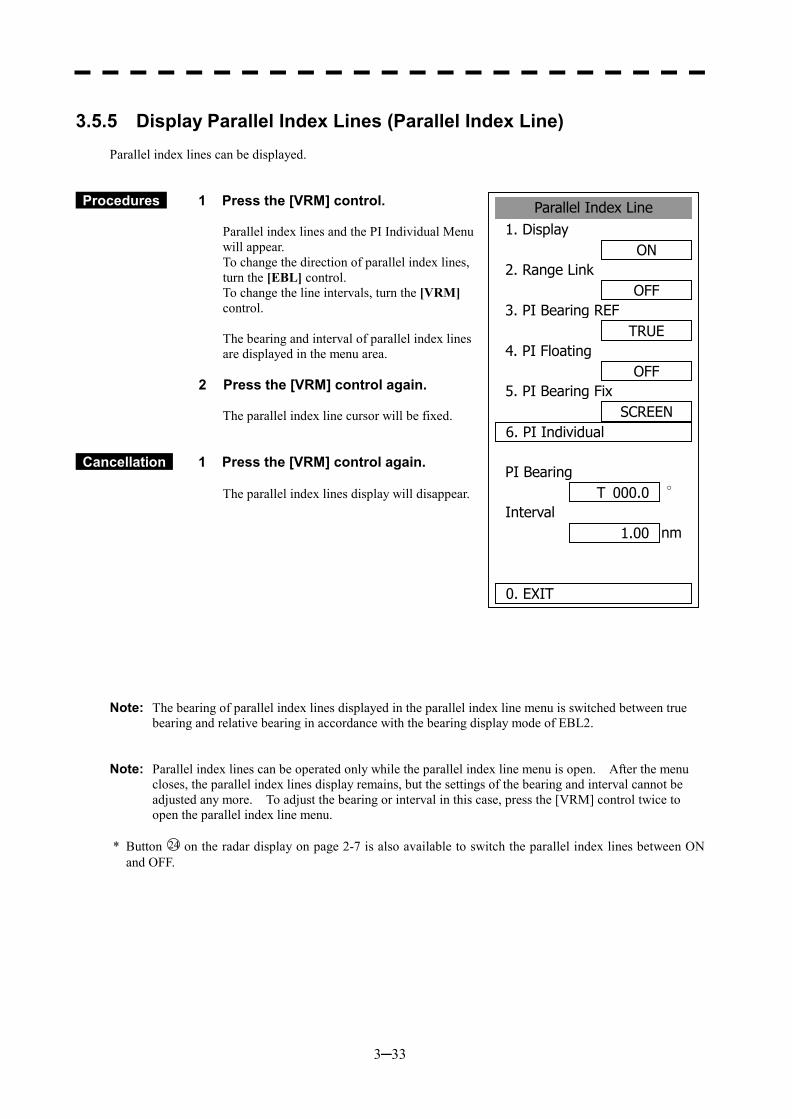
3─33
3.5.5 Display Parallel Index Lines (Parallel Index Line)
Parallel index lines can be displayed.
Procedures 1 Press the [VRM] control. Parallel index lines and the PI Individual Menu will appear. To change the direction of parallel index lines, turn the [EBL] control. To change the line intervals, turn the [VRM] control. The bearing and interval of parallel index lines are displayed in the menu area.
2 Press the [VRM] control again.
The parallel index line cursor will be fixed.
Cancellation 1 Press the [VRM] control again.
The parallel index lines display will disappear.
Note: The bearing of parallel index lines displayed in the parallel index line menu is switched between true bearing and relative bearing in accordance with the bearing display mode of EBL2.
Note: Parallel index lines can be operated only while the parallel index line menu is open. After the menu
closes, the parallel index lines display remains, but the settings of the bearing and interval cannot be adjusted any more. To adjust the bearing or interval in this case, press the [VRM] control twice to open the parallel index line menu.
* Button 24 on the radar display on page 2-7 is also available to switch the parallel index lines between ON
and OFF.
Parallel Index Line1. Display
ON2. Range Link
OFF3. PI Bearing REF
TRUE4. PI Floating
OFF5. PI Bearing Fix
SCREEN6. PI Individual
PI Bearing°
Interval nm
0. EXIT
1.00
T 000.0
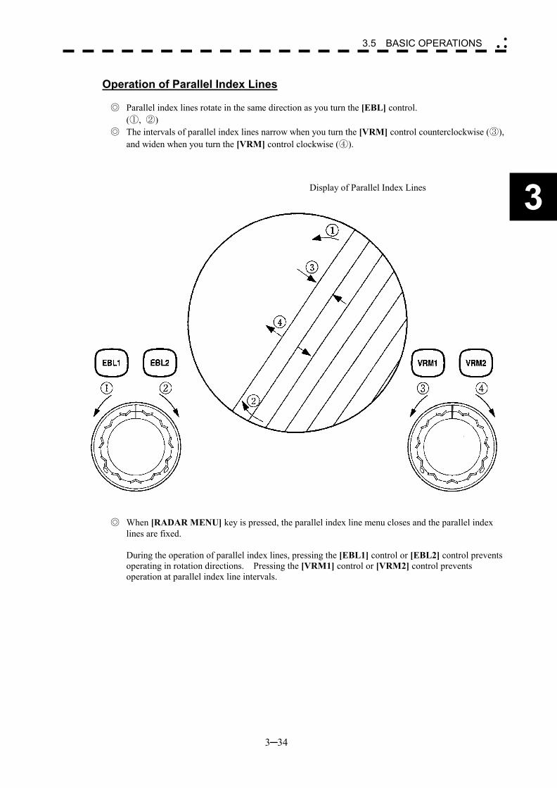
3─34
3
3.5 BASIC OPERATIONS �
� �
Operation of Parallel Index Lines
◎ Parallel index lines rotate in the same direction as you turn the [EBL] control.
(①, ②) ◎ The intervals of parallel index lines narrow when you turn the [VRM] control counterclockwise (③),
and widen when you turn the [VRM] control clockwise (④).
Display of Parallel Index Lines
◎ When [RADAR MENU] key is pressed, the parallel index line menu closes and the parallel index
lines are fixed.
During the operation of parallel index lines, pressing the [EBL1] control or [EBL2] control prevents operating in rotation directions. Pressing the [VRM1] control or [VRM2] control prevents operation at parallel index line intervals.
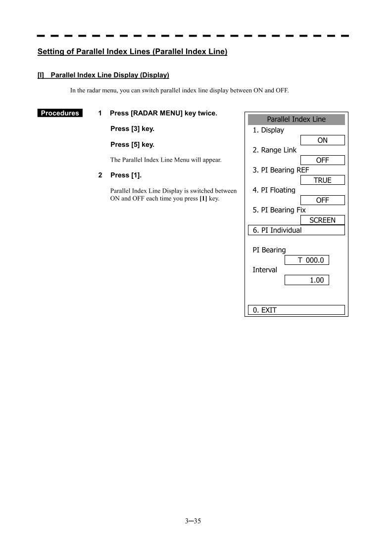
3─35
Parallel Index Line1. Display
ON2. Range Link
OFF3. PI Bearing REF
TRUE4. PI Floating
OFF5. PI Bearing Fix
SCREEN6. PI Individual
PI Bearing
Interval
0. EXIT
1.00
T 000.0
Setting of Parallel Index Lines (Parallel Index Line)
[I] Parallel Index Line Display (Display) In the radar menu, you can switch parallel index line display between ON and OFF.
Procedures 1 Press [RADAR MENU] key twice.
Press [3] key. Press [5] key.
The Parallel Index Line Menu will appear.
2 Press [1].
Parallel Index Line Display is switched between ON and OFF each time you press [1] key.
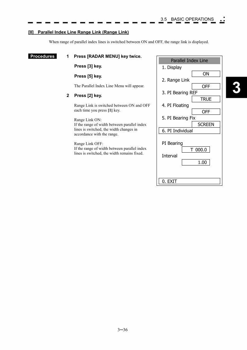
3─36
3
3.5 BASIC OPERATIONS �
� �
Parallel Index Line1. Display
ON2. Range Link
OFF3. PI Bearing REF
TRUE4. PI Floating
OFF5. PI Bearing Fix
SCREEN6. PI Individual
PI Bearing
Interval
0. EXIT
1.00
T 000.0
[II] Parallel Index Line Range Link (Range Link) When range of parallel index lines is switched between ON and OFF, the range link is displayed.
Procedures 1 Press [RADAR MENU] key twice.
Press [3] key. Press [5] key.
The Parallel Index Line Menu will appear.
2 Press [2] key.
Range Link is switched between ON and OFF each time you press [1] key. Range Link ON: If the range of width between parallel index lines is switched, the width changes in accordance with the range. Range Link OFF: If the range of width between parallel index lines is switched, the width remains fixed.
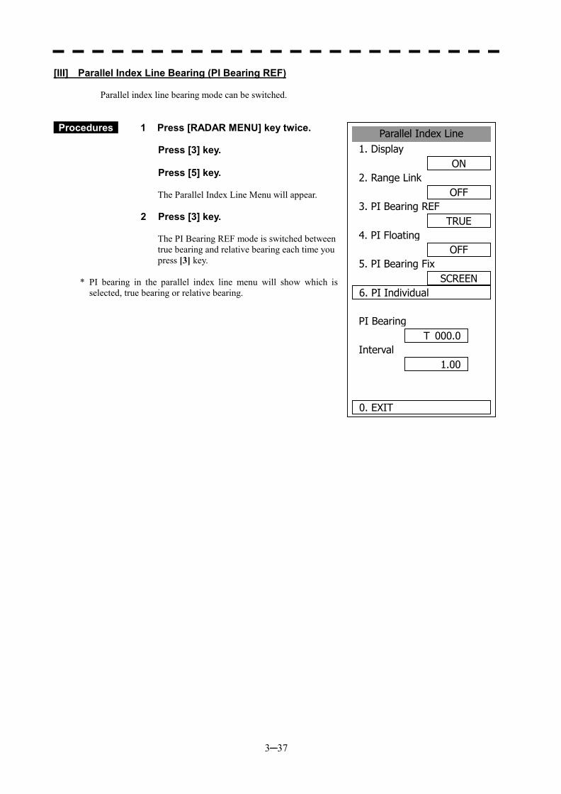
3─37
Parallel Index Line1. Display
ON2. Range Link
OFF3. PI Bearing REF
TRUE4. PI Floating
OFF5. PI Bearing Fix
SCREEN6. PI Individual
PI Bearing
Interval
0. EXIT
1.00
T 000.0
[III] Parallel Index Line Bearing (PI Bearing REF) Parallel index line bearing mode can be switched.
Procedures 1 Press [RADAR MENU] key twice.
Press [3] key. Press [5] key.
The Parallel Index Line Menu will appear.
2 Press [3] key.
The PI Bearing REF mode is switched between true bearing and relative bearing each time you press [3] key.
* PI bearing in the parallel index line menu will show which is
selected, true bearing or relative bearing.
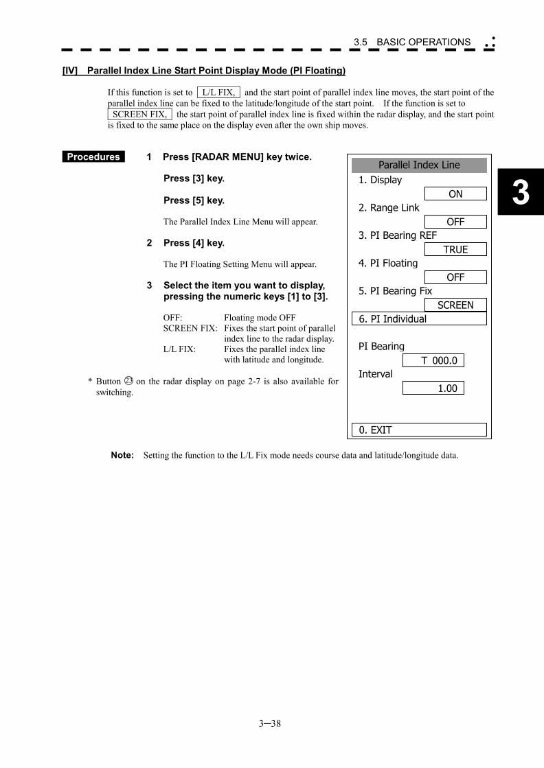
3─38
3
3.5 BASIC OPERATIONS �
� �
Parallel Index Line1. Display
ON2. Range Link
OFF3. PI Bearing REF
TRUE4. PI Floating
OFF5. PI Bearing Fix
SCREEN6. PI Individual
PI Bearing
Interval
0. EXIT
1.00
T 000.0
[IV] Parallel Index Line Start Point Display Mode (PI Floating) If this function is set to L/L FIX, and the start point of parallel index line moves, the start point of the parallel index line can be fixed to the latitude/longitude of the start point. If the function is set to SCREEN FIX, the start point of parallel index line is fixed within the radar display, and the start point is fixed to the same place on the display even after the own ship moves.
Procedures 1 Press [RADAR MENU] key twice.
Press [3] key. Press [5] key.
The Parallel Index Line Menu will appear.
2 Press [4] key.
The PI Floating Setting Menu will appear.
3 Select the item you want to display,
pressing the numeric keys [1] to [3].
OFF: Floating mode OFF SCREEN FIX: Fixes the start point of parallel
index line to the radar display. L/L FIX: Fixes the parallel index line
with latitude and longitude.
* Button 23 on the radar display on page 2-7 is also available for switching.
Note: Setting the function to the L/L Fix mode needs course data and latitude/longitude data.
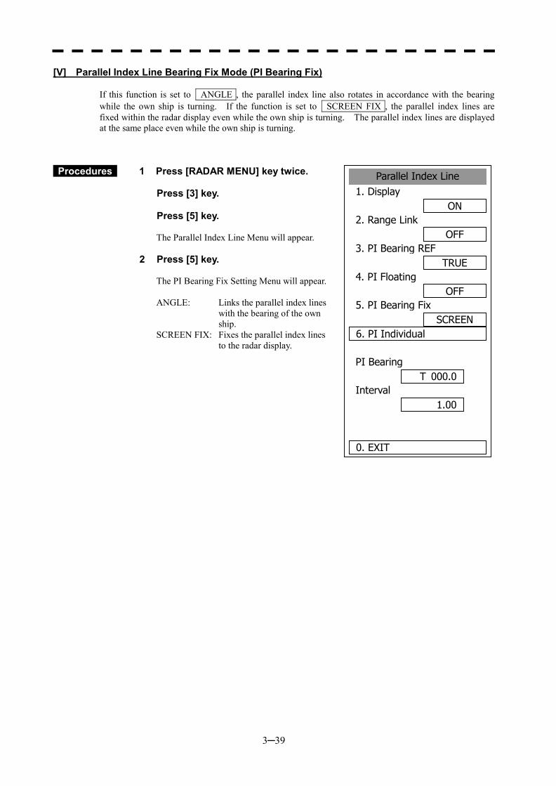
3─39
Parallel Index Line1. Display
ON2. Range Link
OFF3. PI Bearing REF
TRUE4. PI Floating
OFF5. PI Bearing Fix
SCREEN6. PI Individual
PI Bearing
Interval
0. EXIT
1.00
T 000.0
[V] Parallel Index Line Bearing Fix Mode (PI Bearing Fix) If this function is set to ANGLE , the parallel index line also rotates in accordance with the bearing while the own ship is turning. If the function is set to SCREEN FIX , the parallel index lines are fixed within the radar display even while the own ship is turning. The parallel index lines are displayed at the same place even while the own ship is turning.
Procedures 1 Press [RADAR MENU] key twice.
Press [3] key. Press [5] key.
The Parallel Index Line Menu will appear.
2 Press [5] key.
The PI Bearing Fix Setting Menu will appear. ANGLE: Links the parallel index lines
with the bearing of the own ship.
SCREEN FIX: Fixes the parallel index lines to the radar display.
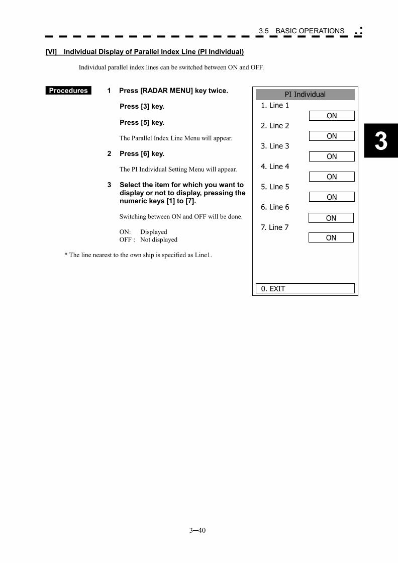
3─40
3
3.5 BASIC OPERATIONS �
� �
PI Individual1. Line 1
ON2. Line 2
ON3. Line 3
ON4. Line 4
ON5. Line 5
ON6. Line 6
7. Line 7
0. EXIT
ON
ON
[VI] Individual Display of Parallel Index Line (PI Individual) Individual parallel index lines can be switched between ON and OFF.
Procedures 1 Press [RADAR MENU] key twice.
Press [3] key. Press [5] key.
The Parallel Index Line Menu will appear.
2 Press [6] key.
The PI Individual Setting Menu will appear.
3 Select the item for which you want to display or not to display, pressing the numeric keys [1] to [7]. Switching between ON and OFF will be done. ON: Displayed OFF : Not displayed
* The line nearest to the own ship is specified as Line1.
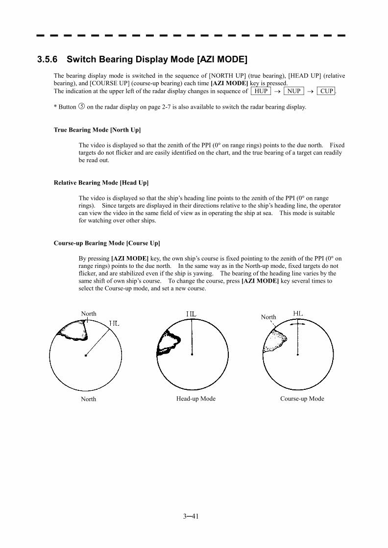
3─41
3.5.6 Switch Bearing Display Mode [AZI MODE]
The bearing display mode is switched in the sequence of [NORTH UP] (true bearing), [HEAD UP] (relative bearing), and [COURSE UP] (course-up bearing) each time [AZI MODE] key is pressed. The indication at the upper left of the radar display changes in sequence of HUP � NUP � CUP . * Button 5 on the radar display on page 2-7 is also available to switch the radar bearing display.
True Bearing Mode [North Up]
The video is displayed so that the zenith of the PPI (0� on range rings) points to the due north. Fixed targets do not flicker and are easily identified on the chart, and the true bearing of a target can readily be read out.
Relative Bearing Mode [Head Up]
The video is displayed so that the ship’s heading line points to the zenith of the PPI (0� on range rings). Since targets are displayed in their directions relative to the ship’s heading line, the operator can view the video in the same field of view as in operating the ship at sea. This mode is suitable for watching over other ships.
Course-up Bearing Mode [Course Up]
By pressing [AZI MODE] key, the own ship’s course is fixed pointing to the zenith of the PPI (0� on range rings) points to the due north. In the same way as in the North-up mode, fixed targets do not flicker, and are stabilized even if the ship is yawing. The bearing of the heading line varies by the same shift of own ship’s course. To change the course, press [AZI MODE] key several times to select the Course-up mode, and set a new course.
North North
North Head-up Mode Course-up Mode
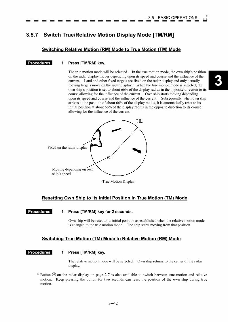
3─42
3
3.5 BASIC OPERATIONS �
� �
3.5.7 Switch True/Relative Motion Display Mode [TM/RM]
Switching Relative Motion (RM) Mode to True Motion (TM) Mode
Procedures 1 Press [TM/RM] key. The true motion mode will be selected. In the true motion mode, the own ship’s position on the radar display moves depending upon its speed and course and the influence of the current. Land and other fixed targets are fixed on the radar display and only actually moving targets move on the radar display. When the true motion mode is selected, the own ship’s position is set to about 66% of the display radius in the opposite direction to its course allowing for the influence of the current. Own ship starts moving depending upon its speed and course and the influence of the current. Subsequently, when own ship arrives at the position of about 66% of the display radius, it is automatically reset to its initial position at about 66% of the display radius in the opposite direction to its course allowing for the influence of the current.
Resetting Own Ship to its Initial Position in True Motion (TM) Mode
Procedures 1 Press [TM/RM] key for 2 seconds. Own ship will be reset to its initial position as established when the relative motion mode is changed to the true motion mode. The ship starts moving from that position.
Switching True Motion (TM) Mode to Relative Motion (RM) Mode
Procedures 1 Press [TM/RM] key. The relative motion mode will be selected. Own ship returns to the center of the radar display.
* Button 4 on the radar display on page 2-7 is also available to switch between true motion and relative motion. Keep pressing the button for two seconds can reset the position of the own ship during true motion.
Fixed on the radar display
Moving depending on own ship’s speed
True Motion Display
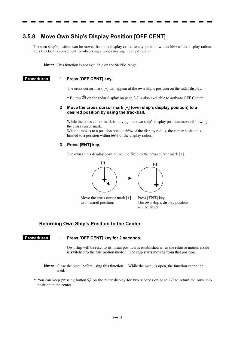
3─43
3.5.8 Move Own Ship’s Display Position [OFF CENT]
The own ship’s position can be moved from the display center to any position within 66% of the display radius. This function is convenient for observing a wide coverage in any direction.
Note: This function is not available on the 96 NM range.
Procedures 1 Press [OFF CENT] key.
The cross cursor mark [+] will appear at the own ship’s position on the radar display. * Button 20 on the radar display on page 2-7 is also available to activate OFF Center.
2 Move the cross cursor mark [+] (own ship’s display position) to a desired position by using the trackball. While the cross cursor mark is moving, the own ship’s display position moves following the cross cursor mark. When it moves to a position outside 66% of the display radius, the center position is limited to a position within 66% of the display radius.
3 Press [ENT] key. The own ship’s display position will be fixed to the cross cursor mark [+].
Returning Own Ship’s Position to the Center
Procedures 1 Press [OFF CENT] key for 2 seconds.
Own ship will be reset to its initial position as established when the relative motion mode is switched to the true motion mode. The ship starts moving from that position.
Note: Close the menu before using this function. While the menu is open, the function cannot be used.
* You can keep pressing button 20 on the radar display for two seconds on page 2-7 to return the own ship
position to the center.
HL HL
Move the cross cursor mark [+] to a desired position.
Press [ENT] key. The own ship’s display position will be fixed.
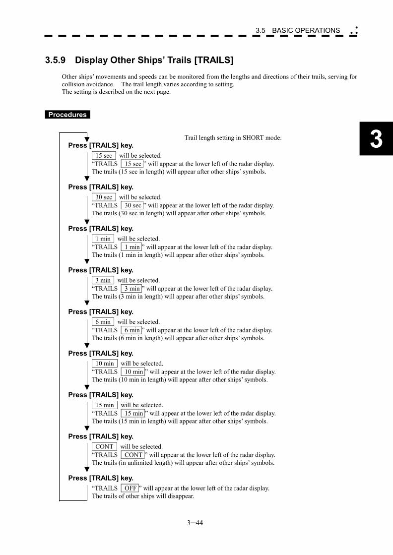
3─44
3
3.5 BASIC OPERATIONS �
� �
3.5.9 Display Other Ships’ Trails [TRAILS]
Other ships’ movements and speeds can be monitored from the lengths and directions of their trails, serving for collision avoidance. The trail length varies according to setting. The setting is described on the next page.
Procedures Trail length setting in SHORT mode:
Press [TRAILS] key. 15 sec will be selected. “TRAILS 15 sec ” will appear at the lower left of the radar display. The trails (15 sec in length) will appear after other ships’ symbols.
Press [TRAILS] key.
30 sec will be selected. “TRAILS 30 sec ” will appear at the lower left of the radar display. The trails (30 sec in length) will appear after other ships’ symbols.
Press [TRAILS] key.
1 min will be selected. “TRAILS 1 min ” will appear at the lower left of the radar display. The trails (1 min in length) will appear after other ships’ symbols.
Press [TRAILS] key.
3 min will be selected. “TRAILS 3 min ” will appear at the lower left of the radar display. The trails (3 min in length) will appear after other ships’ symbols.
Press [TRAILS] key.
6 min will be selected. “TRAILS 6 min ” will appear at the lower left of the radar display. The trails (6 min in length) will appear after other ships’ symbols.
Press [TRAILS] key.
10 min will be selected. “TRAILS 10 min ” will appear at the lower left of the radar display. The trails (10 min in length) will appear after other ships’ symbols.
Press [TRAILS] key.
15 min will be selected. “TRAILS 15 min ” will appear at the lower left of the radar display. The trails (15 min in length) will appear after other ships’ symbols.
Press [TRAILS] key.
CONT will be selected. “TRAILS CONT ” will appear at the lower left of the radar display. The trails (in unlimited length) will appear after other ships’ symbols.
Press [TRAILS] key.
“TRAILS OFF ” will appear at the lower left of the radar display. The trails of other ships will disappear.
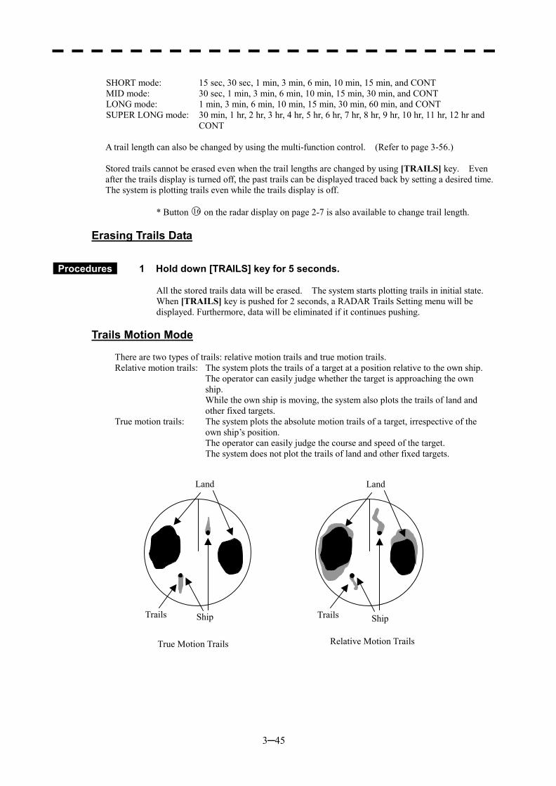
3─45
SHORT mode: 15 sec, 30 sec, 1 min, 3 min, 6 min, 10 min, 15 min, and CONT MID mode: 30 sec, 1 min, 3 min, 6 min, 10 min, 15 min, 30 min, and CONT LONG mode: 1 min, 3 min, 6 min, 10 min, 15 min, 30 min, 60 min, and CONT SUPER LONG mode: 30 min, 1 hr, 2 hr, 3 hr, 4 hr, 5 hr, 6 hr, 7 hr, 8 hr, 9 hr, 10 hr, 11 hr, 12 hr and
CONT
A trail length can also be changed by using the multi-function control. (Refer to page 3-56.) Stored trails cannot be erased even when the trail lengths are changed by using [TRAILS] key. Even after the trails display is turned off, the past trails can be displayed traced back by setting a desired time. The system is plotting trails even while the trails display is off.
* Button 16 on the radar display on page 2-7 is also available to change trail length.
Erasing Trails Data
Procedures 1 Hold down [TRAILS] key for 5 seconds. All the stored trails data will be erased. The system starts plotting trails in initial state. When [TRAILS] key is pushed for 2 seconds, a RADAR Trails Setting menu will be displayed. Furthermore, data will be eliminated if it continues pushing.
Trails Motion Mode
There are two types of trails: relative motion trails and true motion trails. Relative motion trails: The system plots the trails of a target at a position relative to the own ship. The operator can easily judge whether the target is approaching the own
ship. While the own ship is moving, the system also plots the trails of land and
other fixed targets. True motion trails: The system plots the absolute motion trails of a target, irrespective of the
own ship’s position. The operator can easily judge the course and speed of the target. The system does not plot the trails of land and other fixed targets.
Land
ShipTrails
Land
Ship Trails
True Motion Trails Relative Motion Trails
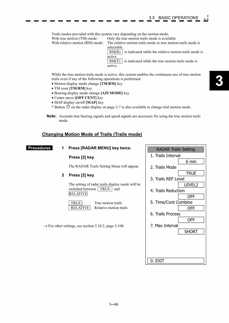
3─46
3
3.5 BASIC OPERATIONS �
� �
Trails modes provided with this system vary depending on the motion mode. With true motion (TM) mode: Only the true motion trails mode is available. With relative motion (RM) mode: The relative motion trails mode or true motion trails mode is
selectable. RM(R) is indicated while the relative motion trails mode is
active. RM(T) is indicated while the true motion trails mode is
active. While the true motion trails mode is active, this system enables the continuous use of true motion trails even if any of the following operations is performed: � Motion display mode change [TM/RM] key � TM reset [TM/RM] key � Bearing display mode change [AZI MODE] key � Center move [OFF CENT] key � MAP display on/off [MAP] key * Button 17 on the radar display on page 2-7 is also available to change trial motion mode.
Note: Accurate true bearing signals and speed signals are necessary for using the true motion trails
mode.
Changing Motion Mode of Trails (Trails mode)
Procedures 1 Press [RADAR MENU] key twice. Press [2] key.
The RADAR Trails Setting Menu will appear.
2 Press [2] key.
The setting of radar trails display mode will be switched between TRUE and RELATIVE. TRUE : True motion trails RELATIVE : Relative motion trails
� For other settings, see section 3.10.2, page 3-100
RADAR Trails Setting1. Trails Interval
6 min2. Trails Mode
TRUE3. Trails REF Level
LEVEL24. Trails Reduction
OFF5. Time/Cont Combine
OFF6. Trails Process
OFF7. Max Interval
SHORT
0. EXIT
3─47
3.5.10 Switch Pulse Length (GAIN/PL)
Procedures 1 Press [GAIN/PL] key. The transmitter pulse length changes cyclically in the following sequence each time [GAIN/PL] key is pressed: SP � MP � LP � SP The currently selected pulse length is indicated at the upper left of the radar screen.
The pulse length can be changed only when the range is set to 0.75, 1.5, 3, 6, or 12 NM.
With SP selected: The transmitter pulse becomes shorter, and the range resolution improves. The effect of suppressing sea clutter returns and rain/snow clutter returns heightens.
Recommended condition for selection:
In bays/harbors where targets are densely crowded Rough sea state due to torrential rain or stormy weather
With MP selected:
The normal transmitter pulse length is set. Both range resolution and sensitivity are appropriately set.
Recommended condition for selection:
General navigation
With LP selected: The transmitter pulse becomes longer, and sensitivity improves. Small targets are zoomed and are easy to observe.
Recommended condition for selection:
Detection of small targets in good weather conditions
* Button 3 on the radar display on page 2-7 is also available to switch pulse width.
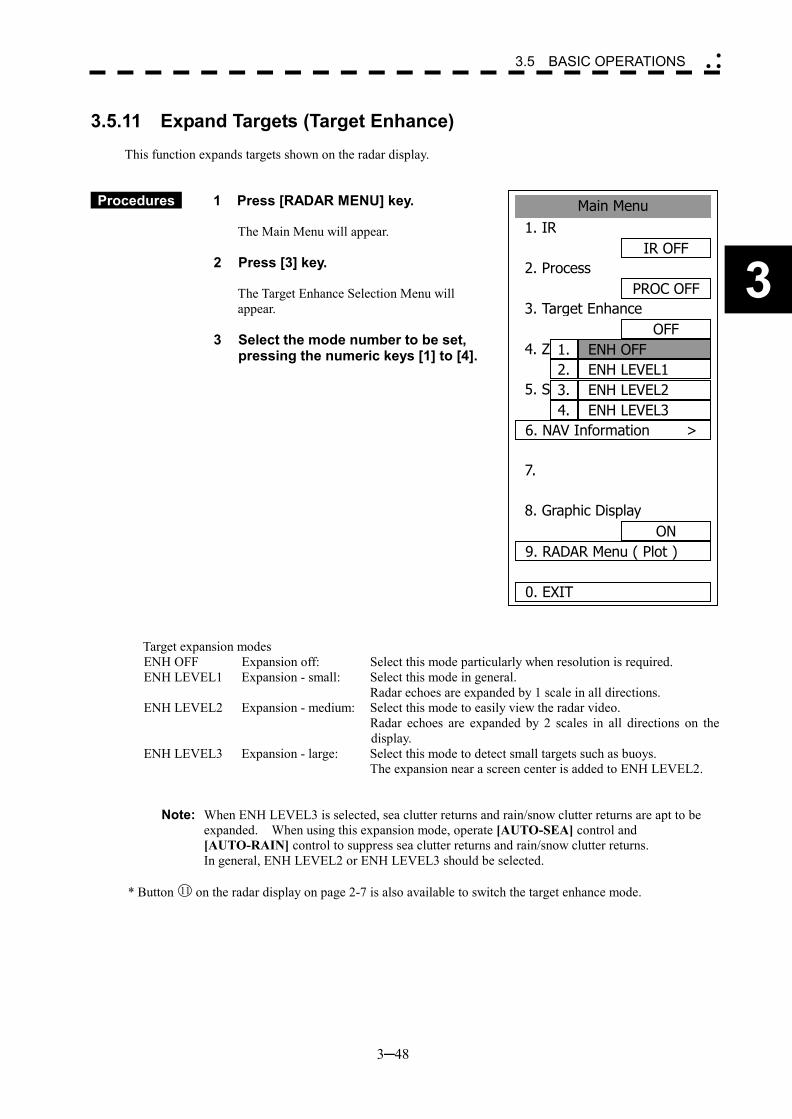
3─48
3
3.5 BASIC OPERATIONS �
� �
Main Menu1. IR
IR OFF2. Process
PROC OFF3. Target Enhance
OFF4. ZOOM
OFF5. START
OFF6. NAV Information >
7.
8. Graphic DisplayON
9. RADAR Menu ( Plot )
0. EXIT
ENH OFF1.ENH LEVEL12.ENH LEVEL23.ENH LEVEL34.
3.5.11 Expand Targets (Target Enhance)
This function expands targets shown on the radar display.
Procedures 1 Press [RADAR MENU] key. The Main Menu will appear.
2 Press [3] key. The Target Enhance Selection Menu will appear.
3 Select the mode number to be set, pressing the numeric keys [1] to [4].
Target expansion modes ENH OFF Expansion off: Select this mode particularly when resolution is required. ENH LEVEL1 Expansion - small: Select this mode in general. Radar echoes are expanded by 1 scale in all directions. ENH LEVEL2 Expansion - medium: Select this mode to easily view the radar video. Radar echoes are expanded by 2 scales in all directions on the
display. ENH LEVEL3 Expansion - large: Select this mode to detect small targets such as buoys. The expansion near a screen center is added to ENH LEVEL2.
Note: When ENH LEVEL3 is selected, sea clutter returns and rain/snow clutter returns are apt to be expanded. When using this expansion mode, operate [AUTO-SEA] control and [AUTO-RAIN] control to suppress sea clutter returns and rain/snow clutter returns. In general, ENH LEVEL2 or ENH LEVEL3 should be selected.
* Button 11 on the radar display on page 2-7 is also available to switch the target enhance mode.
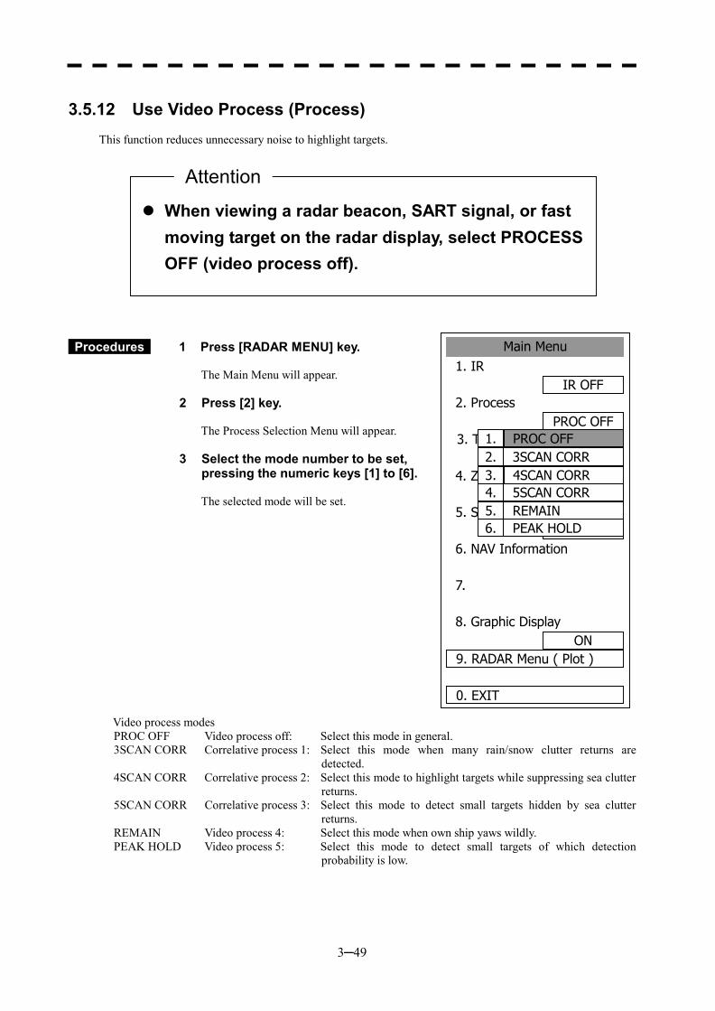
3─49
��When viewing a radar beacon, SART signal, or fast moving target on the radar display, select PROCESS OFF (video process off).
Main Menu1. IR
IR OFF2. Process
PROC OFF3. Target Enhance
OFF4. Zoom
OFF5. SART
OFF6. NAV Information
7.
8. Graphic DisplayON
9. RADAR Menu ( Plot )
0. EXIT
4SCAN CORR3.5SCAN CORR4.
PROC OFF1.3SCAN CORR2.
REMAIN5.PEAK HOLD6.
3.5.12 Use Video Process (Process)
This function reduces unnecessary noise to highlight targets.
Procedures 1 Press [RADAR MENU] key. The Main Menu will appear.
2 Press [2] key. The Process Selection Menu will appear.
3 Select the mode number to be set, pressing the numeric keys [1] to [6]. The selected mode will be set.
Video process modes PROC OFF Video process off: Select this mode in general. 3SCAN CORR Correlative process 1: Select this mode when many rain/snow clutter returns are
detected. 4SCAN CORR Correlative process 2: Select this mode to highlight targets while suppressing sea clutter
returns. 5SCAN CORR Correlative process 3: Select this mode to detect small targets hidden by sea clutter
returns. REMAIN Video process 4: Select this mode when own ship yaws wildly. PEAK HOLD Video process 5: Select this mode to detect small targets of which detection
probability is low.
Attention
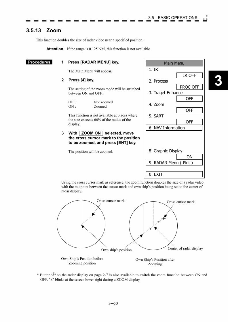
3─50
3
3.5 BASIC OPERATIONS �
� �
3.5.13 Zoom
This function doubles the size of radar video near a specified position.
Attention If the range is 0.125 NM, this function is not available.
Procedures 1 Press [RADAR MENU] key. The Main Menu will appear.
2 Press [4] key. The setting of the zoom mode will be switched between ON and OFF. OFF : Not zoomed ON : Zoomed This function is not available at places where the size exceeds 66% of the radius of the display.
3 With ZOOM ON selected, move the cross cursor mark to the position to be zoomed, and press [ENT] key. The position will be zoomed.
Using the cross cursor mark as reference, the zoom function doubles the size of a radar video with the midpoint between the cursor mark and own ship’s position being set to the center of radar display.
* Button 9 on the radar display on page 2-7 is also available to switch the zoom function between ON and OFF. "x" blinks at the screen lower right during a ZOOM display.
Cross cursor mark
Own ship’s position Center of radar display
Cross cursor mark
Own Ship’s Position before Zooming position
Own Ship’s Position after Zooming
Main Menu1. IR
IR OFF2. Process
PROC OFF3. Traget Enhance
OFF4. Zoom
OFF5. SART
OFF6. NAV Information
8. Graphic DisplayON
9. RADAR Menu ( Plot )
0. EXIT
3─51
3.5.14 Use Marker [MOB]
The marker function displays a dotted line from the marker input position to the own ship’s position, and indicates the range, bearing, and required time from the own ship to the marker.
Procedures 1 Press [MOB] key. A marker will be displayed at the own ship’s position on the radar display at the moment when [MOB] key is pressed. The own ship and the marker are connected with a dotted line. Even when the own ship moves, the marker is fixed at the latitude and longitude. Thus, if a marker is put to an important position, the ship can return to the position regarding the marker as a target.
Cancellation 1 Hold down [MOB] key for 2 seconds.
The marker will disappear.
3─52
3
3.5 BASIC OPERATIONS �
� �
3.5.15 Marking [MARK]
A maximum of 20 marks can be indicated at arbitrary positions on the radar display. A mark created on the radar display holds the latitude and longitude.
[I] Creating Marks
Procedures 1 Press [MARK] key. [□] will appear in the CURSOR field at the upper right of the radar display.
2 Put the cross cursor mark [+] on the position where a mark is to be created, and press [ENT] key. The cross cursor mark [+] will be changed into the [□] mark and fixed on the radar display. To enter more [□] marks, repeat step 2. Up to 20 marks can be entered.
Note: If more than 20 marks are created, the oldest mark is cleared and the newly created mark is displayed.
[II] Clearing Marks
Procedures 1 Press [MARK] key. The [□] mark will appear in the CURSOR field at the upper right of the radar display.
2 Put the cross cursor mark [+] on the mark to be cleared. The [□] mark will disappear. To clear another [□] mark, repeat step 2. To clear all [□] marks, press [MARK] key and then hold down [CLR] key.
* Pressing button 19 on the radar display on page 2-7 changes the cursor mode. When "□" appears, the cross cursor is available to create "□" mark.
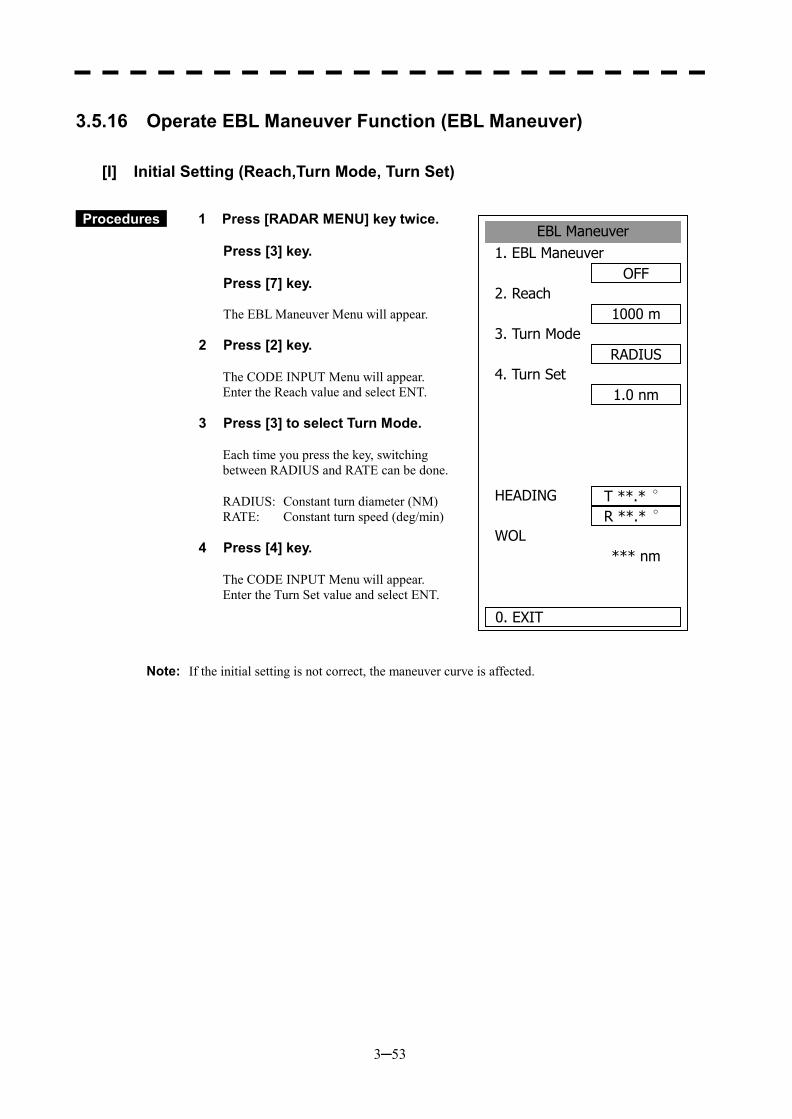
3─53
3.5.16 Operate EBL Maneuver Function (EBL Maneuver)
[I] Initial Setting (Reach,Turn Mode, Turn Set)
Procedures 1 Press [RADAR MENU] key twice. Press [3] key. Press [7] key. The EBL Maneuver Menu will appear.
2 Press [2] key.
The CODE INPUT Menu will appear. Enter the Reach value and select ENT.
3 Press [3] to select Turn Mode.
Each time you press the key, switching between RADIUS and RATE can be done.
RADIUS: Constant turn diameter (NM) RATE: Constant turn speed (deg/min)
4 Press [4] key.
The CODE INPUT Menu will appear. Enter the Turn Set value and select ENT.
Note: If the initial setting is not correct, the maneuver curve is affected.
EBL Maneuver1. EBL Maneuver
OFF2. Reach
1000 m3. Turn Mode
RADIUS4. Turn Set
1.0 nm
HEADING R **.* °
WOL *** nm
0. EXIT
T **.* °
3─54
3
3.5 BASIC OPERATIONS �
� �
[II] Creating Maneuver Curve (EBL Maneuver)
Procedures 1 Press [1] key while the EBL Maneuver menu is open.
EBL Maneuver will be set to ON. A supplemental line, a maneuver curve, and WOL will appear on the radar display.
2 Set the starting point of the supplemental line using the trackball, and set the bearing of the supplemental line using the [EBL] control.
The bearing of the supplemental line will be the final bearing in which the own ship is to move. The position of WOL will change depending on the bearing of the supplemental line. If the WOL is behind the own ship’s position, the line color of WOL will change.
3 Press [ENT] key.
The setting will be determined. However, if the WOL is behind the own ship’s position at this point, the pressing of [ENT] key is rejected, and the setting is not determined.
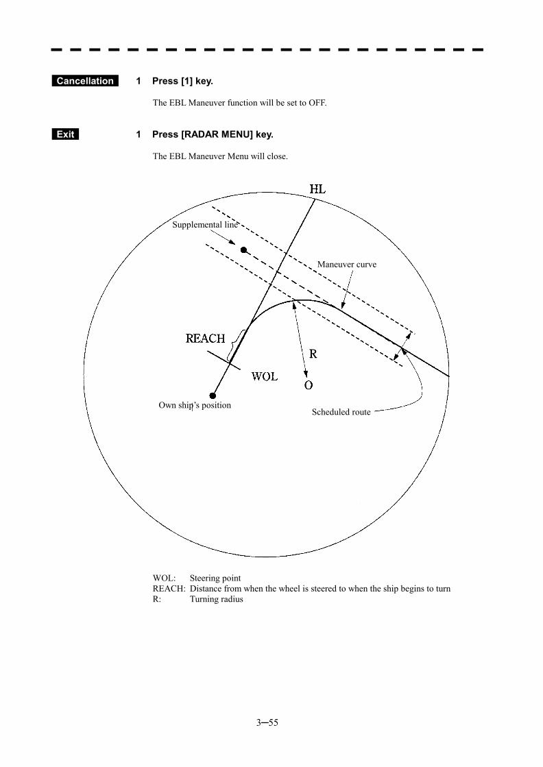
3─55
Cancellation 1 Press [1] key.
The EBL Maneuver function will be set to OFF.
Exit 1 Press [RADAR MENU] key.
The EBL Maneuver Menu will close.
WOL: Steering point REACH: Distance from when the wheel is steered to when the ship begins to turn R: Turning radius
Supplemental line
Maneuver curve
Own ship’s position Scheduled route
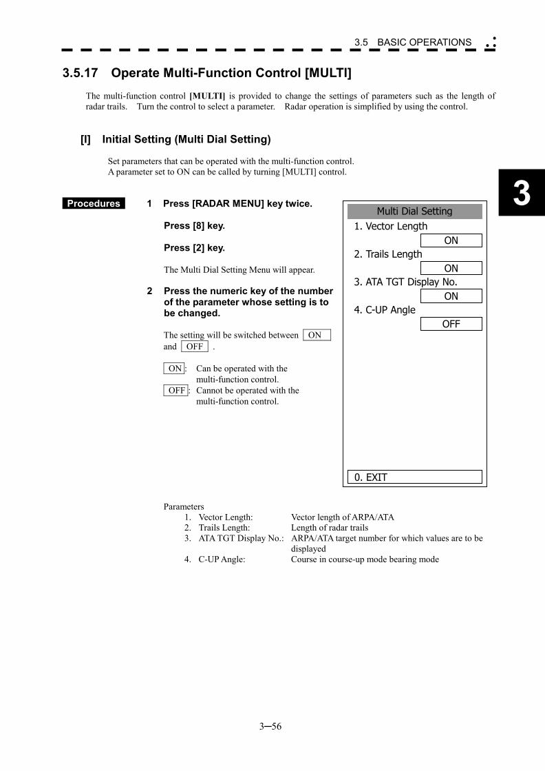
3─56
3
3.5 BASIC OPERATIONS �
� �
3.5.17 Operate Multi-Function Control [MULTI]
The multi-function control [MULTI] is provided to change the settings of parameters such as the length of radar trails. Turn the control to select a parameter. Radar operation is simplified by using the control.
[I] Initial Setting (Multi Dial Setting)
Set parameters that can be operated with the multi-function control. A parameter set to ON can be called by turning [MULTI] control.
Procedures 1 Press [RADAR MENU] key twice. Press [8] key. Press [2] key. The Multi Dial Setting Menu will appear.
2 Press the numeric key of the number
of the parameter whose setting is to be changed. The setting will be switched between ON and OFF . ON : Can be operated with the
multi-function control. OFF : Cannot be operated with the
multi-function control. Parameters
1. Vector Length: Vector length of ARPA/ATA 2. Trails Length: Length of radar trails 3. ATA TGT Display No.: ARPA/ATA target number for which values are to be
displayed 4. C-UP Angle: Course in course-up mode bearing mode
Multi Dial Setting1. Vector Length
ON2. Trails Length
ON3. ATA TGT Display No.
ON4. C-UP Angle
OFF
0. EXIT
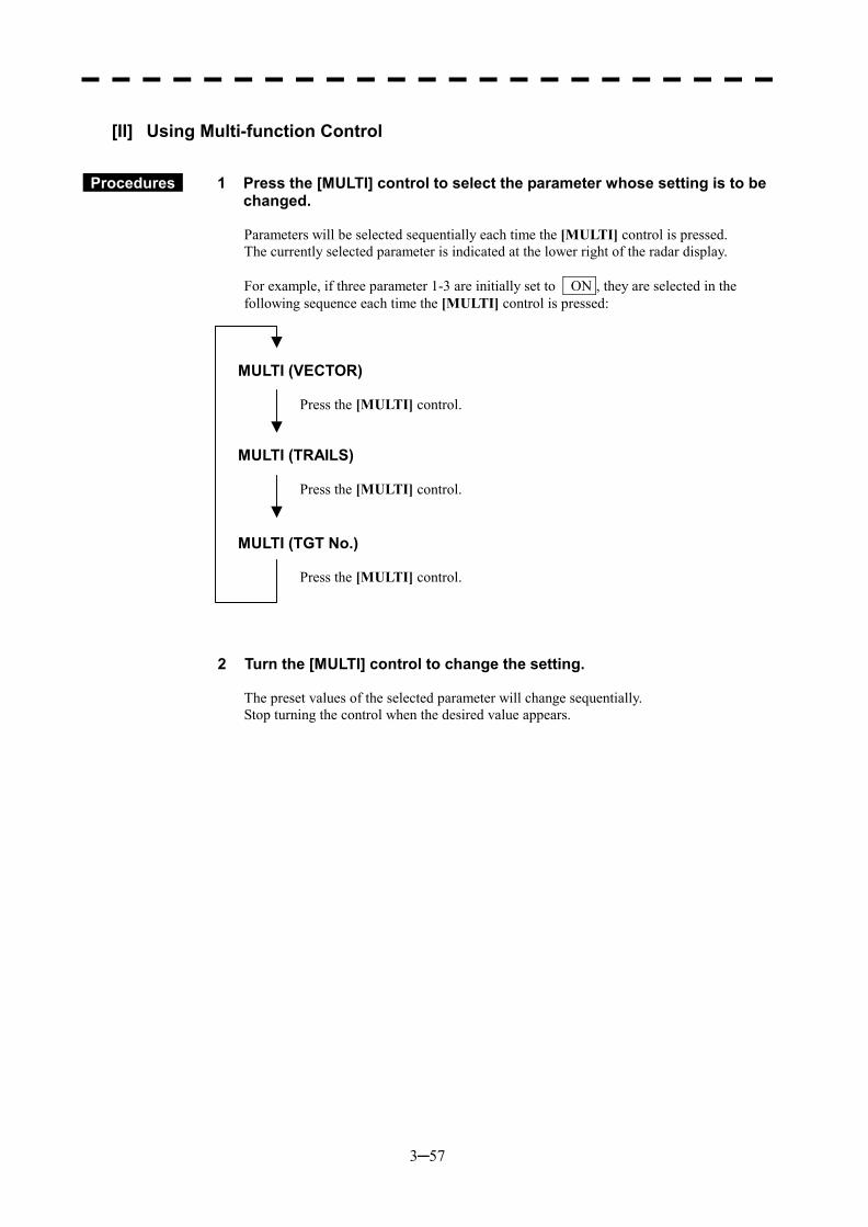
3─57
[II] Using Multi-function Control
Procedures 1 Press the [MULTI] control to select the parameter whose setting is to be changed. Parameters will be selected sequentially each time the [MULTI] control is pressed. The currently selected parameter is indicated at the lower right of the radar display. For example, if three parameter 1-3 are initially set to ON , they are selected in the following sequence each time the [MULTI] control is pressed:
MULTI (VECTOR)
Press the [MULTI] control.
MULTI (TRAILS)
Press the [MULTI] control.
MULTI (TGT No.)
Press the [MULTI] control.
2 Turn the [MULTI] control to change the setting.
The preset values of the selected parameter will change sequentially. Stop turning the control when the desired value appears.
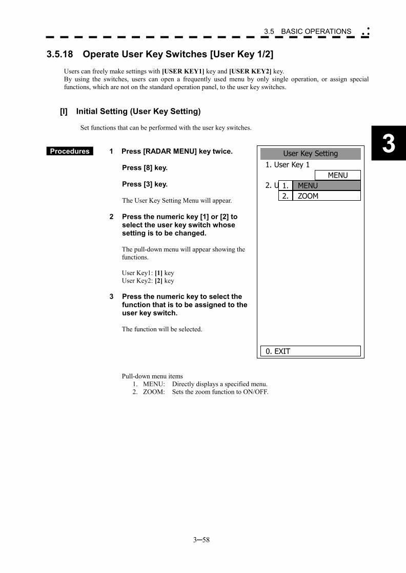
3─58
3
3.5 BASIC OPERATIONS �
� �
3.5.18 Operate User Key Switches [User Key 1/2]
Users can freely make settings with [USER KEY1] key and [USER KEY2] key. By using the switches, users can open a frequently used menu by only single operation, or assign special functions, which are not on the standard operation panel, to the user key switches.
[I] Initial Setting (User Key Setting)
Set functions that can be performed with the user key switches.
Procedures 1 Press [RADAR MENU] key twice. Press [8] key. Press [3] key. The User Key Setting Menu will appear. 2 Press the numeric key [1] or [2] to
select the user key switch whose setting is to be changed.
The pull-down menu will appear showing the functions. User Key1: [1] key User Key2: [2] key
3 Press the numeric key to select the function that is to be assigned to the user key switch.
The function will be selected. Pull-down menu items
1. MENU: Directly displays a specified menu. 2. ZOOM: Sets the zoom function to ON/OFF.
User Key Setting1. User Key 1
MENU2. User Key 2
MENU S.C.
0. EXIT
MENUZOOM
1.2.
3─59
[II] Using User Key Switches (Directly displaying a specified menu)
Preset the menu that is to be displayed with the user key switch.
Setting the menu that is to be displayed with User Key 1:
Procedures 1 Perform the general menu open procedure to open the menu that is to be directly displayed with User Key 1.
2 While the menu is open, hold down [USER KEY1] key for 2 seconds.
The menu will be assigned to [USER KEY1] key.
Setting the menu that is to be displayed with User Key 2:
Procedures 1 Perform the general menu open procedure to open the menu that is to be directly displayed with User Key 2.
2 While the menu is open, hold down [USER KEY2] key for 2 seconds.
The menu will be assigned to [USER KEY2] key.
Directly displaying the menus assigned to the User Keys:
Procedures 1 Press [USER KEY1] key.
The menu assigned to [USER KEY1] key will appear. Subsequently, general menu operation can be performed.
Procedures 1 Press [USER KEY2] key.
The menu assigned to [USER KEY2] key will appear. Subsequently, general menu operation can be performed.
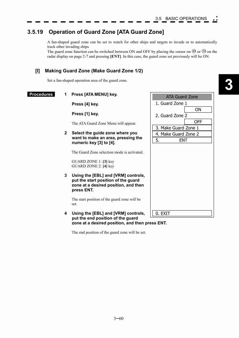
3─60
3
3.5 BASIC OPERATIONS �
� �
ATA Guard Zone 1. Guard Zone 1
ON2. Guard Zone 2
OFF3. Make Guard Zone 1
5. ENT
0. EXIT
4. Make Guard Zone 2
3.5.19 Operation of Guard Zone [ATA Guard Zone]
A fan-shaped guard zone can be set to watch for other ships and targets to invade or to automatically track other invading ships. The guard zone function can be switched between ON and OFF by placing the cursor on 49 or 50 on the radar display on page 2-7 and pressing [ENT]. In this case, the guard zone set previously will be ON.
[I] Making Guard Zone (Make Guard Zone 1/2) Set a fan-shaped operation area of the guard zone.
Procedures 1 Press [ATA MENU] key.
Press [4] key. Press [1] key.
The ATA Guard Zone Menu will appear. 2 Select the guide zone where you
want to make an area, pressing the numeric key [3] to [4].
The Guard Zone selection mode is activated. GUARD ZONE 1: [3] key GUARD ZONE 2: [4] key
3 Using the [EBL] and [VRM] controls,
put the start position of the guard zone at a desired position, and then press ENT. The start position of the guard zone will be set.
4 Using the [EBL] and [VRM] controls,
put the end position of the guard zone at a desired position, and then press ENT. The end position of the guard zone will be set.
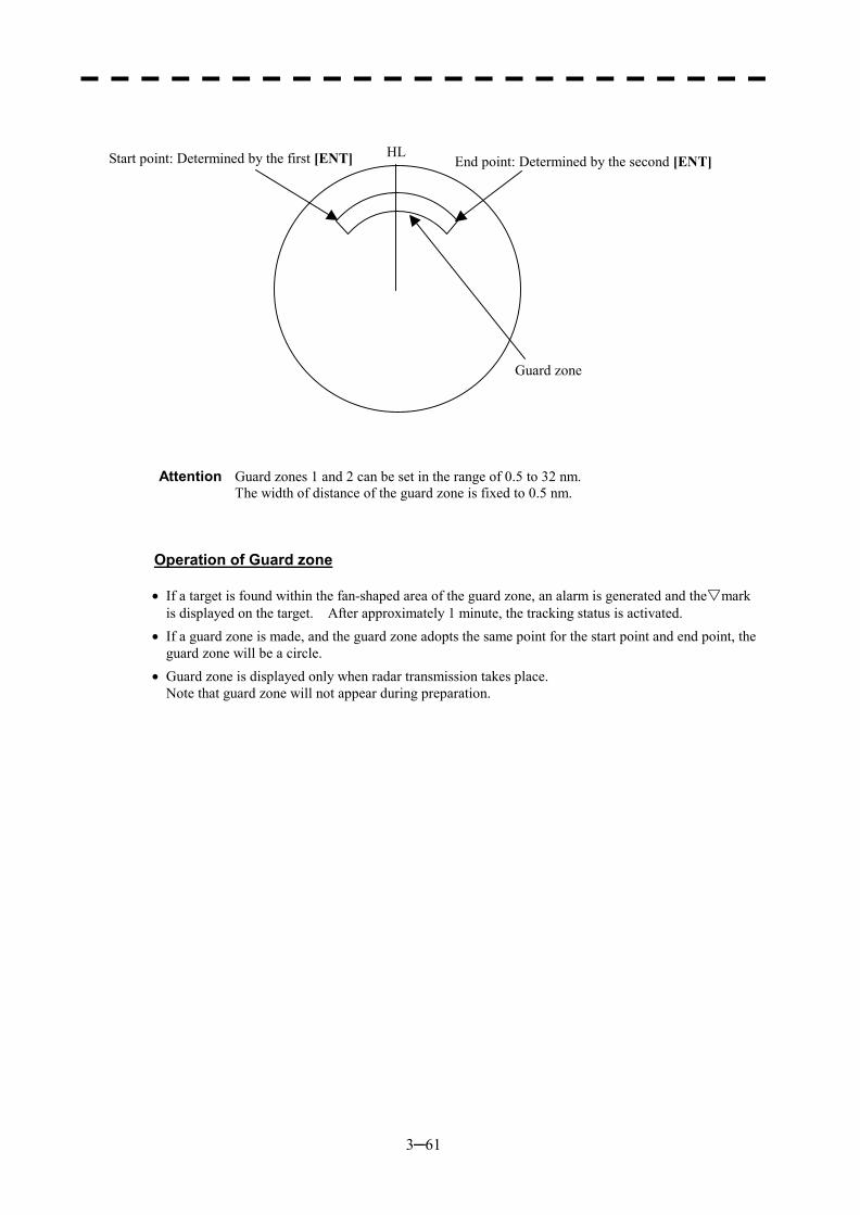
3─61
Attention Guard zones 1 and 2 can be set in the range of 0.5 to 32 nm. The width of distance of the guard zone is fixed to 0.5 nm.
Operation of Guard zone �� If a target is found within the fan-shaped area of the guard zone, an alarm is generated and the▽mark
is displayed on the target. After approximately 1 minute, the tracking status is activated. �� If a guard zone is made, and the guard zone adopts the same point for the start point and end point, the
guard zone will be a circle. �� Guard zone is displayed only when radar transmission takes place.
Note that guard zone will not appear during preparation.
HLStart point: Determined by the first [ENT] End point: Determined by the second [ENT]
Guard zone
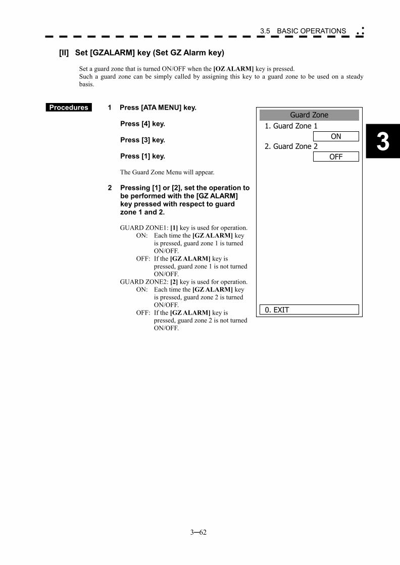
3─62
3
3.5 BASIC OPERATIONS �
� �
Guard Zone1. Guard Zone 1
ON2. Guard Zone 2
OFF
0. EXIT
[II] Set [GZALARM] key (Set GZ Alarm key) Set a guard zone that is turned ON/OFF when the [OZ ALARM] key is pressed. Such a guard zone can be simply called by assigning this key to a guard zone to be used on a steady basis.
Procedures 1 Press [ATA MENU] key.
Press [4] key. Press [3] key. Press [1] key.
The Guard Zone Menu will appear.
2 Pressing [1] or [2], set the operation to be performed with the [GZ ALARM] key pressed with respect to guard zone 1 and 2. GUARD ZONE1: [1] key is used for operation.
ON: Each time the [GZ ALARM] key is pressed, guard zone 1 is turned ON/OFF.
OFF: If the [GZ ALARM] key is pressed, guard zone 1 is not turned ON/OFF.
GUARD ZONE2: [2] key is used for operation. ON: Each time the [GZ ALARM] key
is pressed, guard zone 2 is turned ON/OFF.
OFF: If the [GZ ALARM] key is pressed, guard zone 2 is not turned ON/OFF.
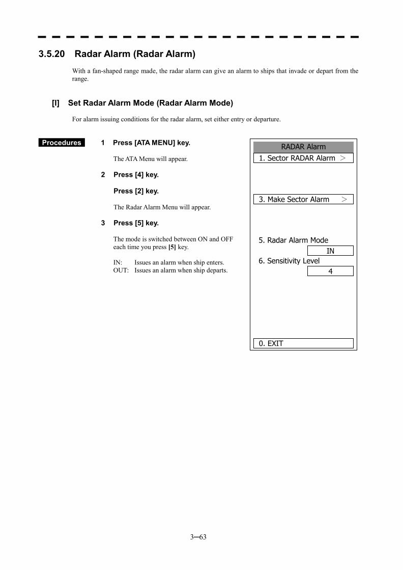
3─63
RADAR Alarm1. Sector RADAR Alarm >
3. Make Sector Alarm >
5. Radar Alarm ModeIN
6. Sensitivity Level4
0. EXIT
3.5.20 Radar Alarm (Radar Alarm) With a fan-shaped range made, the radar alarm can give an alarm to ships that invade or depart from the range.
[I] Set Radar Alarm Mode (Radar Alarm Mode) For alarm issuing conditions for the radar alarm, set either entry or departure.
Procedures 1 Press [ATA MENU] key.
The ATA Menu will appear.
2 Press [4] key. Press [2] key.
The Radar Alarm Menu will appear.
3 Press [5] key.
The mode is switched between ON and OFF each time you press [5] key. IN: Issues an alarm when ship enters. OUT: Issues an alarm when ship departs.
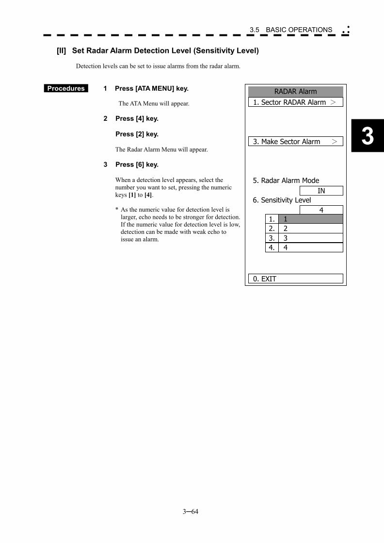
3─64
3
3.5 BASIC OPERATIONS �
� �
RADAR Alarm1. Sector RADAR Alarm >
3. Make Sector Alarm >
5. Radar Alarm ModeIN
6. Sensitivity Level4
0. EXIT
1. 12. 23. 34. 4
[II] Set Radar Alarm Detection Level (Sensitivity Level) Detection levels can be set to issue alarms from the radar alarm.
Procedures 1 Press [ATA MENU] key.
The ATA Menu will appear.
2 Press [4] key. Press [2] key.
The Radar Alarm Menu will appear.
3 Press [6] key.
When a detection level appears, select the number you want to set, pressing the numeric keys [1] to [4].
* As the numeric value for detection level is
larger, echo needs to be stronger for detection. If the numeric value for detection level is low, detection can be made with weak echo to issue an alarm.
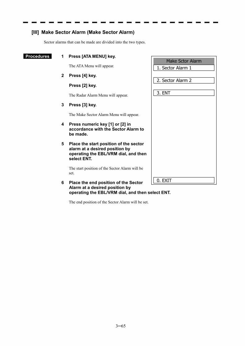
3─65
Make Sctor Alarm1. Sector Alarm 1
2. Sector Alarm 2
3. ENT
0. EXIT
[III] Make Sector Alarm (Make Sector Alarm) Sector alarms that can be made are divided into the two types.
Procedures 1 Press [ATA MENU] key.
The ATA Menu will appear.
2 Press [4] key. Press [2] key.
The Radar Alarm Menu will appear.
3 Press [3] key.
The Make Sector Alarm Menu will appear.
4 Press numeric key [1] or [2] in accordance with the Sector Alarm to be made.
5 Place the start position of the sector
alarm at a desired position by operating the EBL/VRM dial, and then select ENT. The start position of the Sector Alarm will be set.
6 Place the end position of the Sector
Alarm at a desired position by operating the EBL/VRM dial, and then select ENT. The end position of the Sector Alarm will be set.
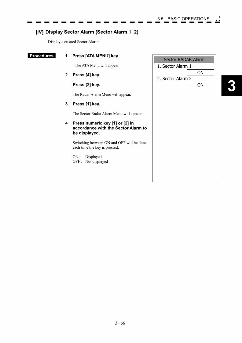
3─66
3
3.5 BASIC OPERATIONS �
� �
Sector RADAR Alarm1. Sector Alarm 1
ON2. Sector Alarm 2
ON
[IV] Display Sector Alarm (Sector Alarm 1, 2) Display a created Sector Alarm.
Procedures 1 Press [ATA MENU] key.
The ATA Menu will appear.
2 Press [4] key. Press [2] key.
The Radar Alarm Menu will appear.
3 Press [1] key.
The Sector Radar Alarm Menu will appear.
4 Press numeric key [1] or [2] in accordance with the Sector Alarm to be displayed.
Switching between ON and OFF will be done each time the key is pressed. ON: Displayed OFF : Not displayed
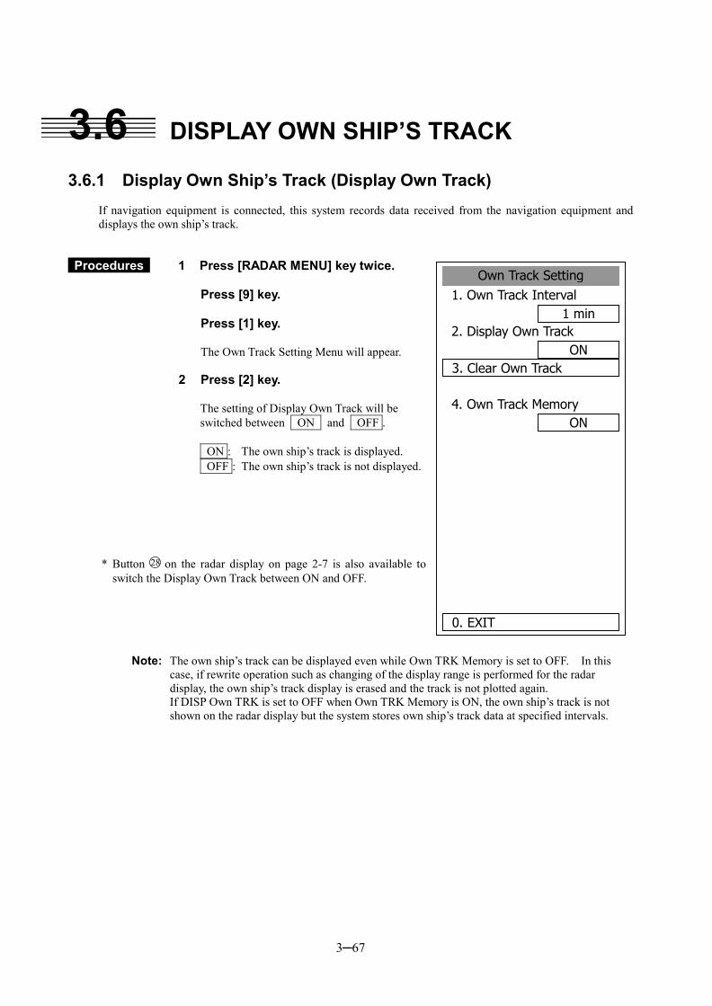
3─67
3.6 DISPLAY OWN SHIP’S TRACK 3.6.1 Display Own Ship’s Track (Display Own Track)
If navigation equipment is connected, this system records data received from the navigation equipment and displays the own ship’s track.
Procedures 1 Press [RADAR MENU] key twice. Press [9] key. Press [1] key. The Own Track Setting Menu will appear.
2 Press [2] key.
The setting of Display Own Track will be switched between ON and OFF . ON : The own ship’s track is displayed. OFF : The own ship’s track is not displayed.
* Button 28 on the radar display on page 2-7 is also available to switch the Display Own Track between ON and OFF.
Note: The own ship’s track can be displayed even while Own TRK Memory is set to OFF. In this case, if rewrite operation such as changing of the display range is performed for the radar display, the own ship’s track display is erased and the track is not plotted again.
If DISP Own TRK is set to OFF when Own TRK Memory is ON, the own ship’s track is not shown on the radar display but the system stores own ship’s track data at specified intervals.
Own Track Setting1. Own Track Interval
1 min2. Display Own Track
ON3. Clear Own Track
4. Own Track MemoryON
0. EXIT
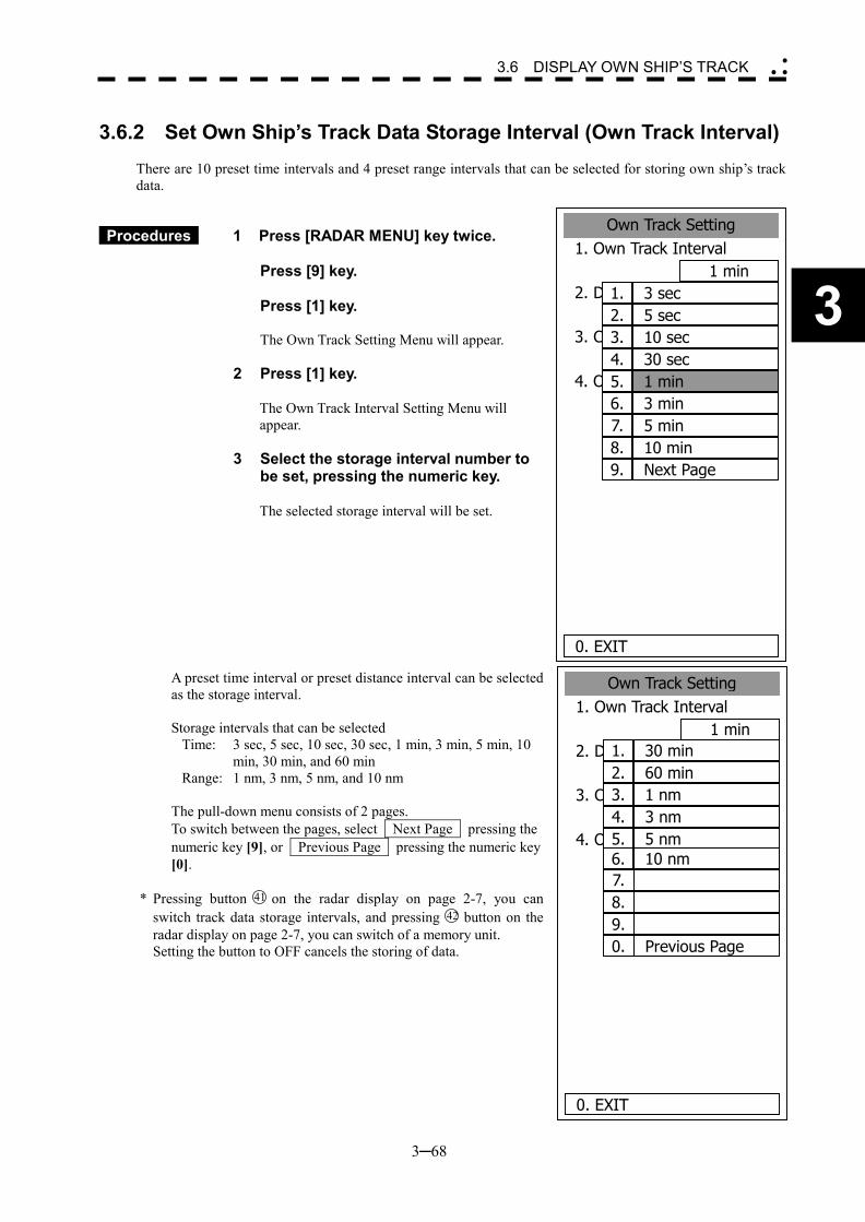
3─68
3
3.6 DISPLAY OWN SHIP’S TRACK �
� �
3.6.2 Set Own Ship’s Track Data Storage Interval (Own Track Interval)
There are 10 preset time intervals and 4 preset range intervals that can be selected for storing own ship’s track data.
Procedures 1 Press [RADAR MENU] key twice. Press [9] key. Press [1] key. The Own Track Setting Menu will appear.
2 Press [1] key.
The Own Track Interval Setting Menu will appear.
3 Select the storage interval number to be set, pressing the numeric key.
The selected storage interval will be set.
A preset time interval or preset distance interval can be selected as the storage interval. Storage intervals that can be selected
Time: 3 sec, 5 sec, 10 sec, 30 sec, 1 min, 3 min, 5 min, 10 min, 30 min, and 60 min
Range: 1 nm, 3 nm, 5 nm, and 10 nm The pull-down menu consists of 2 pages. To switch between the pages, select Next Page pressing the numeric key [9], or Previous Page pressing the numeric key [0].
* Pressing button 41 on the radar display on page 2-7, you can
switch track data storage intervals, and pressing 42 button on the radar display on page 2-7, you can switch of a memory unit.
Setting the button to OFF cancels the storing of data.
Own Track Setting1. Own Track Interval
1 min2. DISP Own TRK Color
ALL3. CLR Own TRK Color
WHITE4. Own TRK Memory
OFF
0. EXIT
3 sec1.5 sec2.10 sec3.30 sec4.1 min5.3 min6.5 min7.10 min8.Next Page9.
Own Track Setting1. Own Track Interval
1 min2. DISP Own TRK Colour
ALL3. CLR Own TRK Colour
WHITE4. Own TRK Memory
OFF
0. EXIT
30 min1.60 min2.1 nm3.3 nm4.5 nm5.10 nm6.
7.8.9.
Previous Page0.
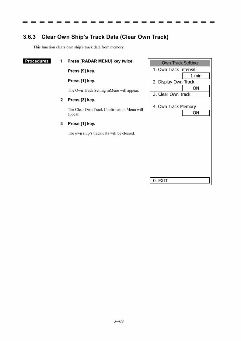
3─69
3.6.3 Clear Own Ship’s Track Data (Clear Own Track)
This function clears own ship’s track data from memory.
Procedures 1 Press [RADAR MENU] key twice. Press [9] key. Press [1] key. The Own Track Setting mMenu will appear.
2 Press [3] key.
The Clear Own Track Confirmation Menu will appear.
3 Press [1] key.
The own ship’s track data will be cleared.
Own Track Setting1. Own Track Interval
1 min2. Display Own Track
ON3. Clear Own Track
4. Own Track MemoryON
0. EXIT
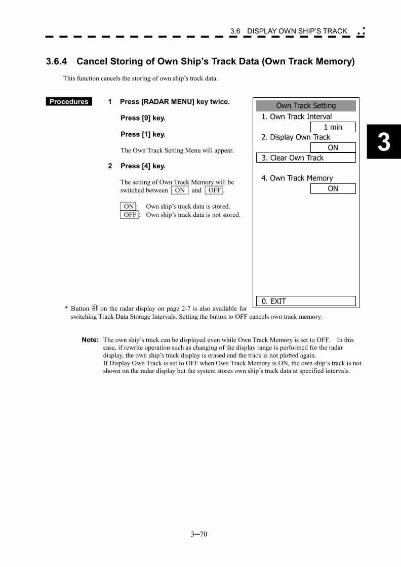
3─70
3
3.6 DISPLAY OWN SHIP’S TRACK �
� �
3.6.4 Cancel Storing of Own Ship’s Track Data (Own Track Memory)
This function cancels the storing of own ship’s track data.
Procedures 1 Press [RADAR MENU] key twice. Press [9] key. Press [1] key. The Own Track Setting Menu will appear.
2 Press [4] key.
The setting of Own Track Memory will be switched between ON and OFF . ON : Own ship’s track data is stored. OFF : Own ship’s track data is not stored.
* Button 41 on the radar display on page 2-7 is also available for switching Track Data Storage Intervals. Setting the button to OFF cancels own track memory.
Note: The own ship’s track can be displayed even while Own Track Memory is set to OFF. In this case, if rewrite operation such as changing of the display range is performed for the radar display, the own ship’s track display is erased and the track is not plotted again.
If Display Own Track is set to OFF when Own Track Memory is ON, the own ship’s track is not shown on the radar display but the system stores own ship’s track data at specified intervals.
Own Track Setting1. Own Track Interval
1 min2. Display Own Track
ON3. Clear Own Track
4. Own Track MemoryON
0. EXIT
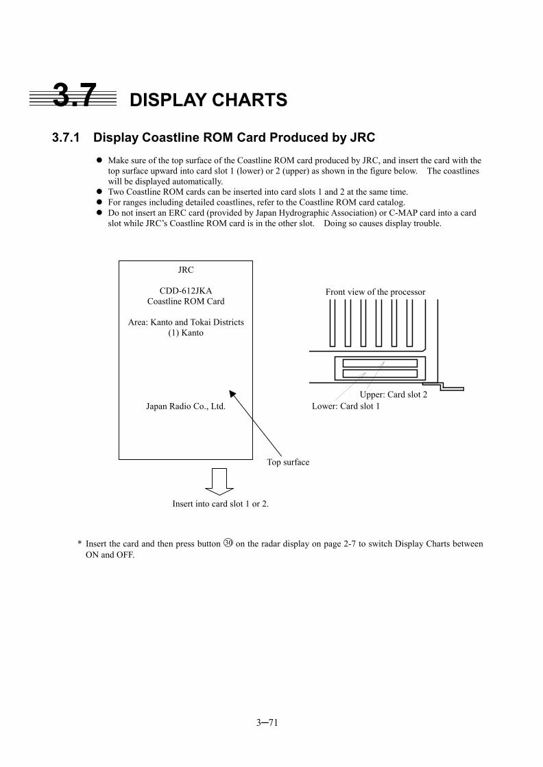
3─71
3.7 DISPLAY CHARTS 3.7.1 Display Coastline ROM Card Produced by JRC
��Make sure of the top surface of the Coastline ROM card produced by JRC, and insert the card with the
top surface upward into card slot 1 (lower) or 2 (upper) as shown in the figure below. The coastlines will be displayed automatically.
��Two Coastline ROM cards can be inserted into card slots 1 and 2 at the same time. ��For ranges including detailed coastlines, refer to the Coastline ROM card catalog. ��Do not insert an ERC card (provided by Japan Hydrographic Association) or C-MAP card into a card
slot while JRC’s Coastline ROM card is in the other slot. Doing so causes display trouble.
処理部前面
上段:カードスロット2
下段:カードスロット1
* Insert the card and then press button 30 on the radar display on page 2-7 to switch Display Charts between ON and OFF.
JRC
CDD-612JKA Coastline ROM Card
Area: Kanto and Tokai Districts
(1) Kanto
Japan Radio Co., Ltd.
Top surface
Insert into card slot 1 or 2.
Front view of the processor
Upper: Card slot 2 Lower: Card slot 1
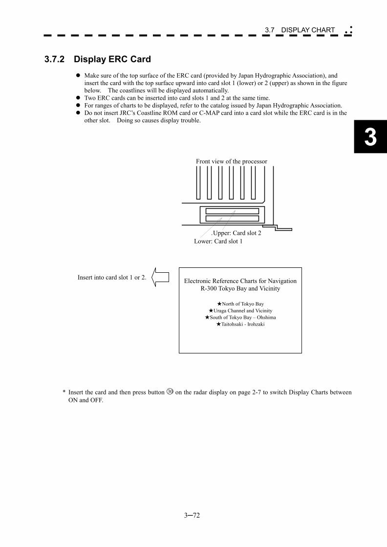
3─72
3
3.7 DISPLAY CHART �
� �
3.7.2 Display ERC Card
��Make sure of the top surface of the ERC card (provided by Japan Hydrographic Association), and
insert the card with the top surface upward into card slot 1 (lower) or 2 (upper) as shown in the figure below. The coastlines will be displayed automatically.
��Two ERC cards can be inserted into card slots 1 and 2 at the same time. ��For ranges of charts to be displayed, refer to the catalog issued by Japan Hydrographic Association. ��Do not insert JRC’s Coastline ROM card or C-MAP card into a card slot while the ERC card is in the
other slot. Doing so causes display trouble.
処理部前面
上段:カードスロット2
下段:カードスロット1
* Insert the card and then press button 30 on the radar display on page 2-7 to switch Display Charts between ON and OFF.
Electronic Reference Charts for Navigation
R-300 Tokyo Bay and Vicinity
★North of Tokyo Bay ★Uraga Channel and Vicinity
★South of Tokyo Bay – Ohshima ★Taitohsaki - Irohzaki
Front view of the processor
Upper: Card slot 2 Lower: Card slot 1
Insert into card slot 1 or 2.
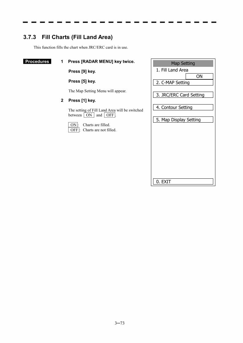
3─73
3.7.3 Fill Charts (Fill Land Area)
This function fills the chart when JRC/ERC card is in use.
Procedures 1 Press [RADAR MENU] key twice. Press [9] key. Press [5] key. The Map Setting Menu will appear.
2 Press [1] key.
The setting of Fill Land Area will be switched between ON and OFF . ON : Charts are filled. OFF : Charts are not filled.
Map Setting1. Fill Land Area
ON2. C-MAP Setting
3. JRC/ERC Card Setting
4. Contour Setting
5. Map Display Setting
0. EXIT
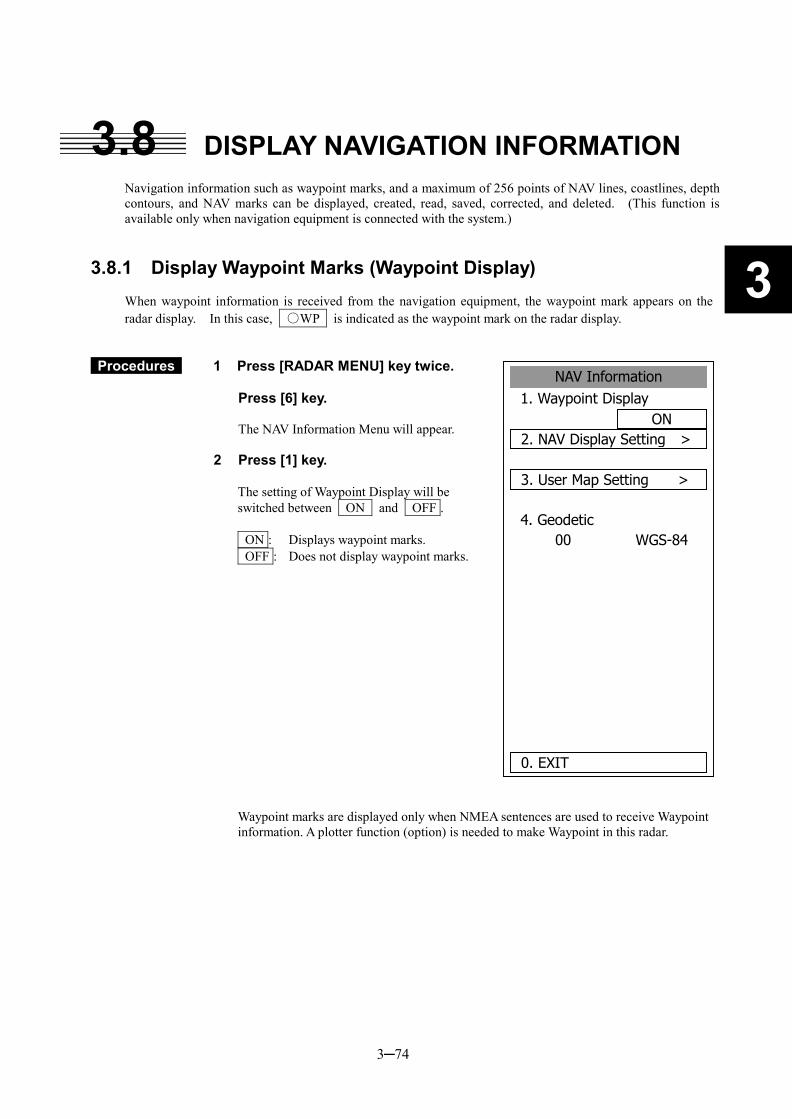
3─74
3
3.8 DISPLAY NAVIGATION INFORMATION
Navigation information such as waypoint marks, and a maximum of 256 points of NAV lines, coastlines, depth contours, and NAV marks can be displayed, created, read, saved, corrected, and deleted. (This function is available only when navigation equipment is connected with the system.)
3.8.1 Display Waypoint Marks (Waypoint Display)
When waypoint information is received from the navigation equipment, the waypoint mark appears on the radar display. In this case, ○WP is indicated as the waypoint mark on the radar display.
Procedures 1 Press [RADAR MENU] key twice. Press [6] key.
The NAV Information Menu will appear.
2 Press [1] key.
The setting of Waypoint Display will be switched between ON and OFF . ON : Displays waypoint marks. OFF : Does not display waypoint marks. Waypoint marks are displayed only when NMEA sentences are used to receive Waypoint information. A plotter function (option) is needed to make Waypoint in this radar.
NAV Information1. Waypoint Display
ON2. NAV Display Setting >
3. User Map Setting >
4. GeodeticWGS-8400
0. EXIT
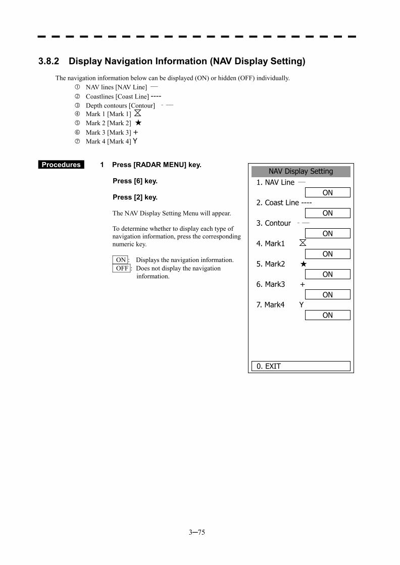
3─75
3.8.2 Display Navigation Information (NAV Display Setting)
The navigation information below can be displayed (ON) or hidden (OFF) individually.
� NAV lines [NAV Line] ― � Coastlines [Coast Line] ---- � Depth contours [Contour] ‐― � Mark 1 [Mark 1] � Mark 2 [Mark 2] ★ � Mark 3 [Mark 3] + Mark 4 [Mark 4] Y
Procedures 1 Press [RADAR MENU] key. Press [6] key. Press [2] key.
The NAV Display Setting Menu will appear. To determine whether to display each type of navigation information, press the corresponding numeric key. ON : Displays the navigation information. OFF : Does not display the navigation
information.
NAV Display Setting1. NAV Line ―
ON2. Coast Line ----
ON3. Contour ‐―
ON4. Mark1
ON5. Mark2 ★
ON6. Mark3 +
ON7. Mark4 Y
ON
0. EXIT
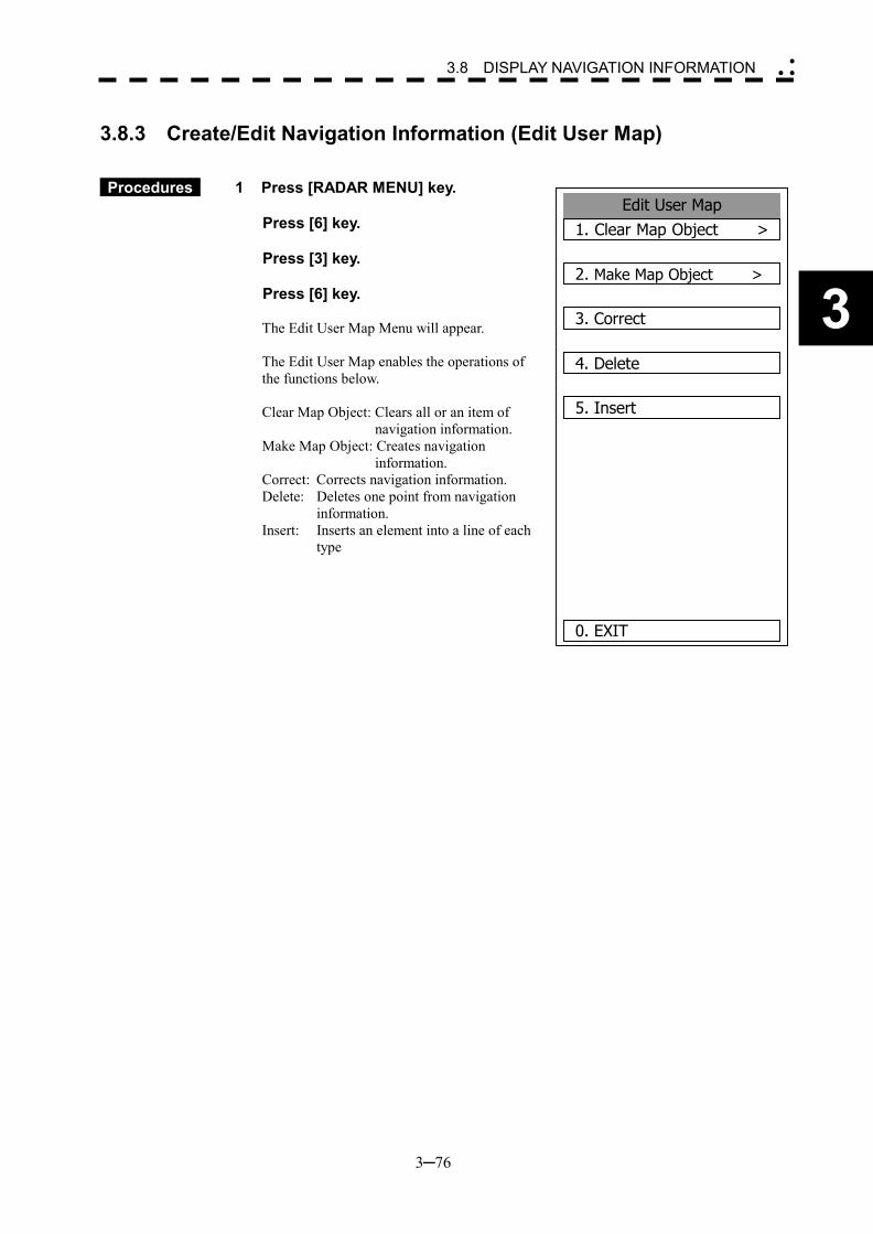
3─76
3
3.8 DISPLAY NAVIGATION INFORMATION �
� �
3.8.3 Create/Edit Navigation Information (Edit User Map)
Procedures 1 Press [RADAR MENU] key. Press [6] key. Press [3] key. Press [6] key.
The Edit User Map Menu will appear. The Edit User Map enables the operations of the functions below. Clear Map Object: Clears all or an item of
navigation information. Make Map Object: Creates navigation
information. Correct: Corrects navigation information. Delete: Deletes one point from navigation
information. Insert: Inserts an element into a line of each
type
Edit User Map1. Clear Map Object >
2. Make Map Object >
3. Correct
4. Delete
5. Insert
0. EXIT
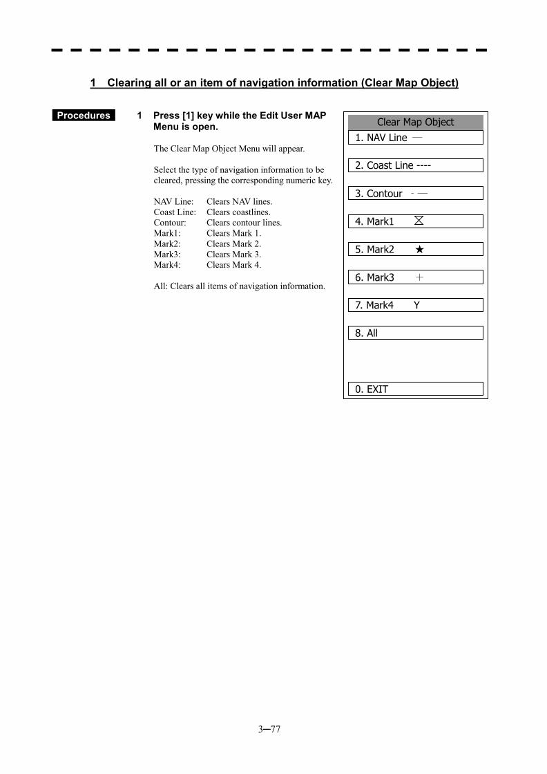
3─77
1 Clearing all or an item of navigation information (Clear Map Object)
Procedures 1 Press [1] key while the Edit User MAP Menu is open.
The Clear Map Object Menu will appear. Select the type of navigation information to be cleared, pressing the corresponding numeric key. NAV Line: Clears NAV lines. Coast Line: Clears coastlines. Contour: Clears contour lines. Mark1: Clears Mark 1. Mark2: Clears Mark 2. Mark3: Clears Mark 3. Mark4: Clears Mark 4. All: Clears all items of navigation information.
Clear Map Object1. NAV Line ―
2. Coast Line ----
3. Contour ‐―
4. Mark1
5. Mark2 ★
6. Mark3 +
7. Mark4 Y
8. All
0. EXIT
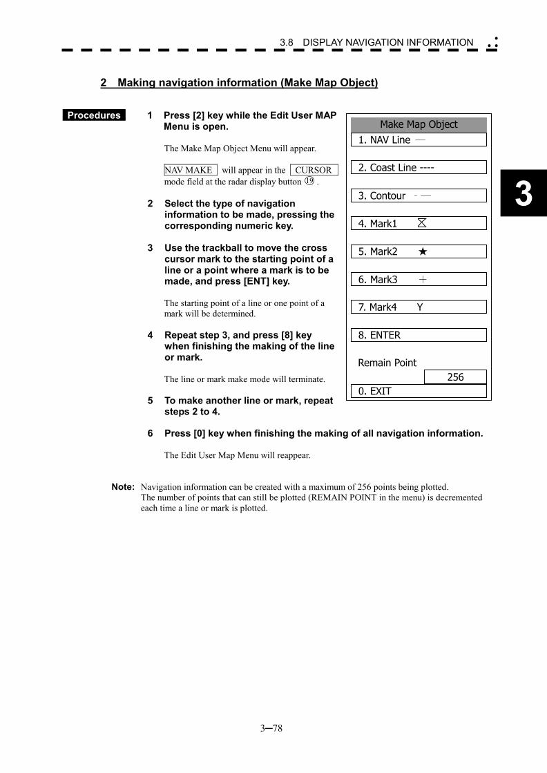
3─78
3
3.8 DISPLAY NAVIGATION INFORMATION �
� �
2 Making navigation information (Make Map Object)
Procedures 1 Press [2] key while the Edit User MAP Menu is open.
The Make Map Object Menu will appear. NAV MAKE will appear in the CURSOR mode field at the radar display button 19 .
2 Select the type of navigation information to be made, pressing the corresponding numeric key.
3 Use the trackball to move the cross
cursor mark to the starting point of a line or a point where a mark is to be made, and press [ENT] key.
The starting point of a line or one point of a mark will be determined.
4 Repeat step 3, and press [8] key when finishing the making of the line or mark.
The line or mark make mode will terminate.
5 To make another line or mark, repeat steps 2 to 4.
6 Press [0] key when finishing the making of all navigation information.
The Edit User Map Menu will reappear.
Note: Navigation information can be created with a maximum of 256 points being plotted. The number of points that can still be plotted (REMAIN POINT in the menu) is decremented
each time a line or mark is plotted.
Make Map Object1. NAV Line ―
2. Coast Line ----
3. Contour ‐―
4. Mark1
5. Mark2 ★
6. Mark3 +
7. Mark4 Y
8. ENTER
Remain Point256
0. EXIT
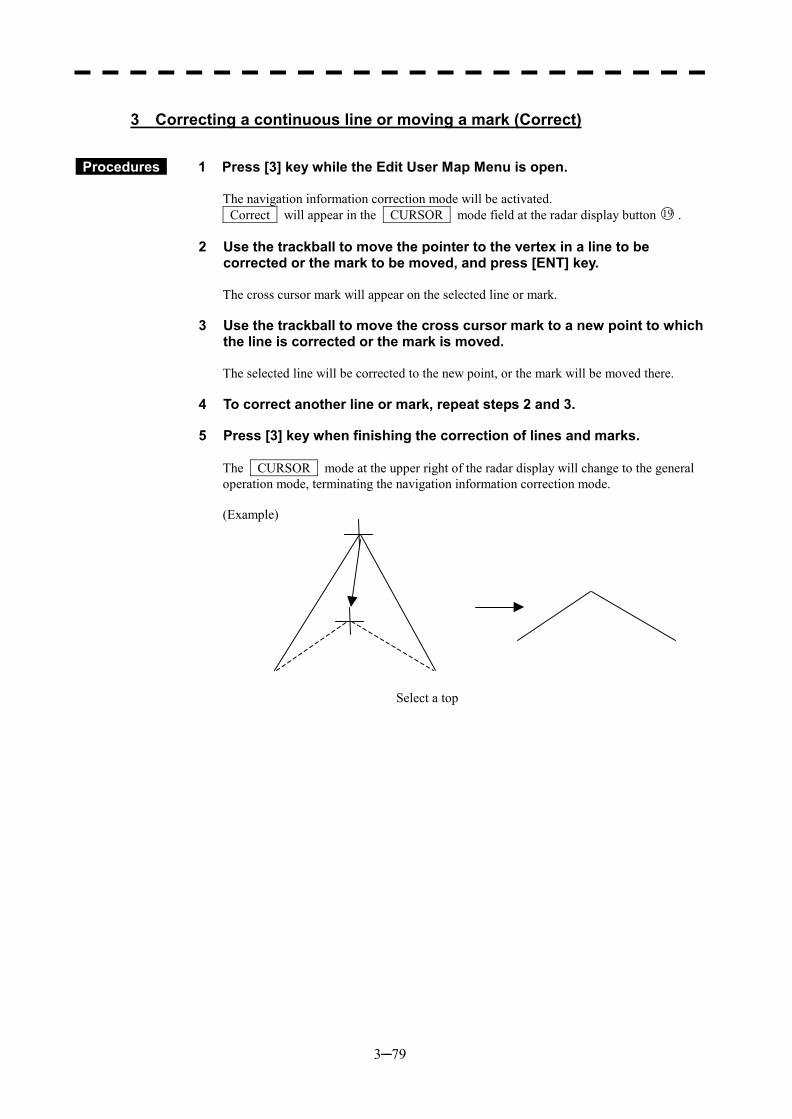
3─79
3 Correcting a continuous line or moving a mark (Correct)
Procedures 1 Press [3] key while the Edit User Map Menu is open.
The navigation information correction mode will be activated. Correct will appear in the CURSOR mode field at the radar display button 19 .
2 Use the trackball to move the pointer to the vertex in a line to be corrected or the mark to be moved, and press [ENT] key.
The cross cursor mark will appear on the selected line or mark.
3 Use the trackball to move the cross cursor mark to a new point to which the line is corrected or the mark is moved.
The selected line will be corrected to the new point, or the mark will be moved there.
4 To correct another line or mark, repeat steps 2 and 3.
5 Press [3] key when finishing the correction of lines and marks.
The CURSOR mode at the upper right of the radar display will change to the general operation mode, terminating the navigation information correction mode. (Example)
Select a top
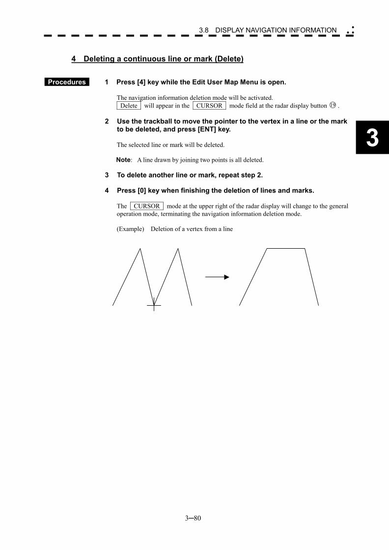
3─80
3
3.8 DISPLAY NAVIGATION INFORMATION �
� �
4 Deleting a continuous line or mark (Delete)
Procedures 1 Press [4] key while the Edit User Map Menu is open. The navigation information deletion mode will be activated. Delete will appear in the CURSOR mode field at the radar display button 19 .
2 Use the trackball to move the pointer to the vertex in a line or the mark to be deleted, and press [ENT] key.
The selected line or mark will be deleted. Note: A line drawn by joining two points is all deleted.
3 To delete another line or mark, repeat step 2.
4 Press [0] key when finishing the deletion of lines and marks. The CURSOR mode at the upper right of the radar display will change to the general operation mode, terminating the navigation information deletion mode. (Example) Deletion of a vertex from a line
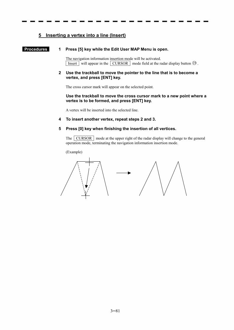
3─81
5 Inserting a vertex into a line (Insert)
Procedures 1 Press [5] key while the Edit User MAP Menu is open.
The navigation information insertion mode will be activated. Insert will appear in the CURSOR mode field at the radar display button 19 .
2 Use the trackball to move the pointer to the line that is to become a vertex, and press [ENT] key.
The cross cursor mark will appear on the selected point.
Use the trackball to move the cross cursor mark to a new point where a vertex is to be formed, and press [ENT] key.
A vertex will be inserted into the selected line.
4 To insert another vertex, repeat steps 2 and 3. 5 Press [0] key when finishing the insertion of all vertices.
The CURSOR mode at the upper right of the radar display will change to the general operation mode, terminating the navigation information insertion mode. (Example)

3─82
3
3.8 DISPLAY NAVIGATION INFORMATION �
� �
3.8.4 Set Navigation Information (User Map Setting)
Procedures 1 Press [RADAR MENU] key. Press [6] key. Press [3] key.
The User Map Setting Menu will appear. Select operation for navigation information, pressing the corresponding numeric key. The selected operation will be performed. Load: Loads navigation information. Unload: Unloads navigation information. Save: Saves navigation information. Erase: Erases navigation information. Edit: Edits navigation information. Shift: Shifts the display position of
navigation information. Shift Clear: Clears position correction
information.
User Map Setting1. Own Ship Position
N 35°23.000’E139°22.345’
2. Load >
3. Unload
4. Save >
5. Erase >
6. Edit User Map >
7. Shift
8. Shift Clear
0. EXIT
3─83
[I] Entering the own ship’s position in manual mode (Own Ship Position)
Use this function to edit the navigation information of any positions other than the own ship’s position.
Procedures 1 Press [1] key while the User Map Setting Menu is open.
The CODE INPUT Menu for entering latitude and longitude of the own ship position will appear.
2 Enter a value as the latitude (xx� xxx.xx’) using the numeric keys [0] to [9].
3 To switch between north latitude and south latitude, press the [MULTI]
control.
Each time the control is pressed, N (north latitude) is changed to S (south latitude), or vice versa.
4 Press [ENT] key.
The latitude entered in manual mode will be determined. Subsequently, enter the longitude.
5 Enter a value as the longitude (xx� xxx.xx’) using the numeric keys [0] to [9].
6 To switch between east longitude and west longitude, press the [MULTI]
control. Each time the control is pressed, E (east longitude) is changed to W (west longitude), or vice versa.
7 Press [ENT] key.
The longitude entered in manual mode will be determined.
* Button on the CODE INPUT Menu is also available instead of the numeric keys.
Note: The own ship’s position manually entered by using the function above is valid only in the User MAP Setting Menu. When control exists from the menu, the manually entered position data is invalidated.
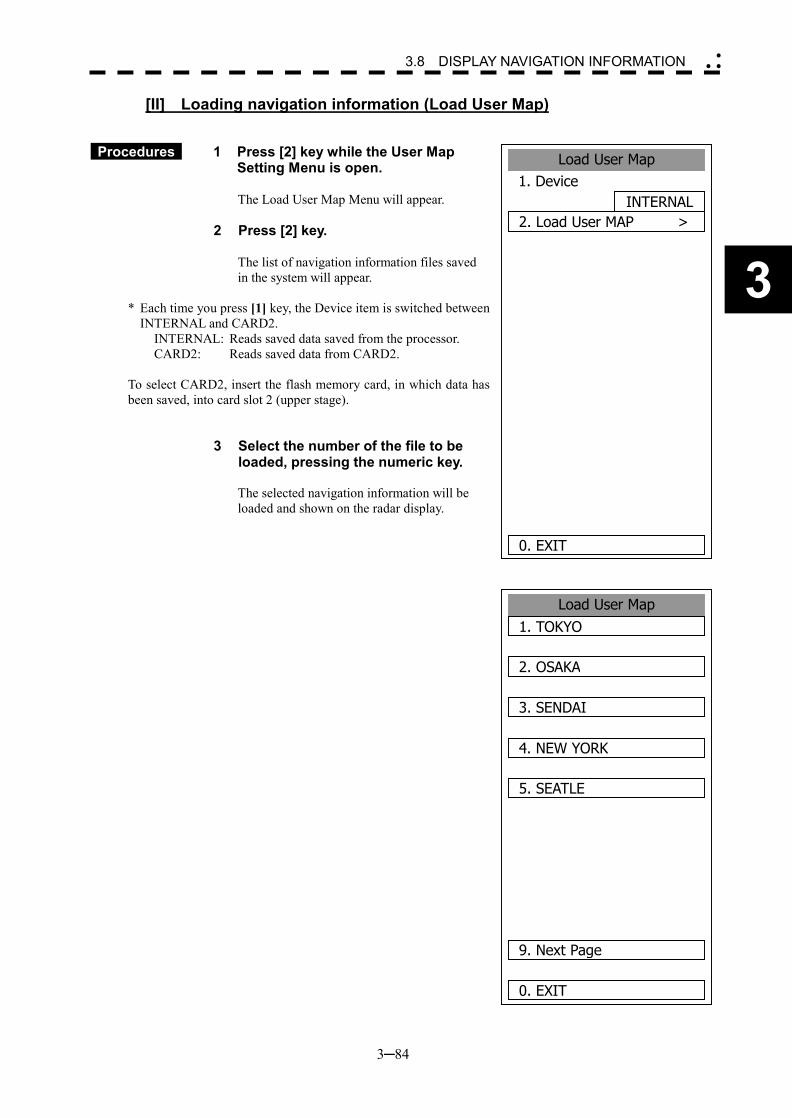
3─84
3
3.8 DISPLAY NAVIGATION INFORMATION �
� �
[II] Loading navigation information (Load User Map)
Procedures 1 Press [2] key while the User Map Setting Menu is open.
The Load User Map Menu will appear.
2 Press [2] key.
The list of navigation information files saved in the system will appear.
* Each time you press [1] key, the Device item is switched between INTERNAL and CARD2.
INTERNAL: Reads saved data saved from the processor. CARD2: Reads saved data from CARD2.
To select CARD2, insert the flash memory card, in which data has been saved, into card slot 2 (upper stage).
3 Select the number of the file to be loaded, pressing the numeric key. The selected navigation information will be loaded and shown on the radar display.
Load User Map1. TOKYO
2. OSAKA
3. SENDAI
4. NEW YORK
5. SEATLE
9. Next Page
0. EXIT
Load User Map1. Device
INTERNAL2. Load User MAP >
0. EXIT
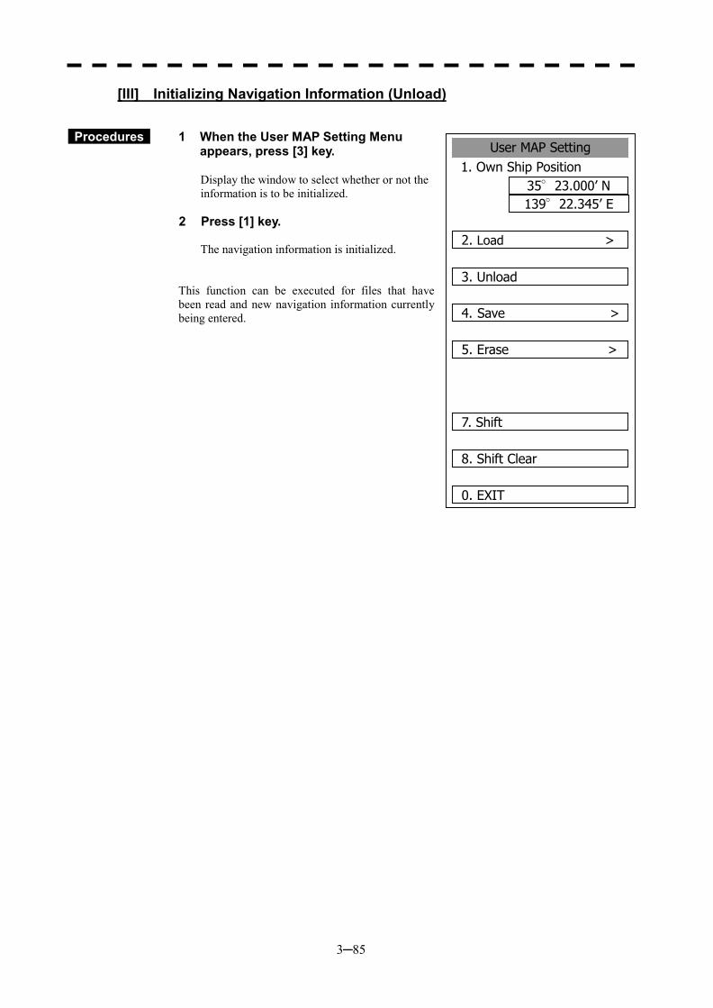
3─85
User MAP Setting1. Own Ship Position
35°23.000’ N139°22.345’ E
2. Load >
3. Unload
4. Save >
5. Erase >
7. Shift
8. Shift Clear
0. EXIT
[III] Initializing Navigation Information (Unload)
Procedures 1 When the User MAP Setting Menu
appears, press [3] key.
Display the window to select whether or not the information is to be initialized.
2 Press [1] key.
The navigation information is initialized.
This function can be executed for files that have been read and new navigation information currently being entered.
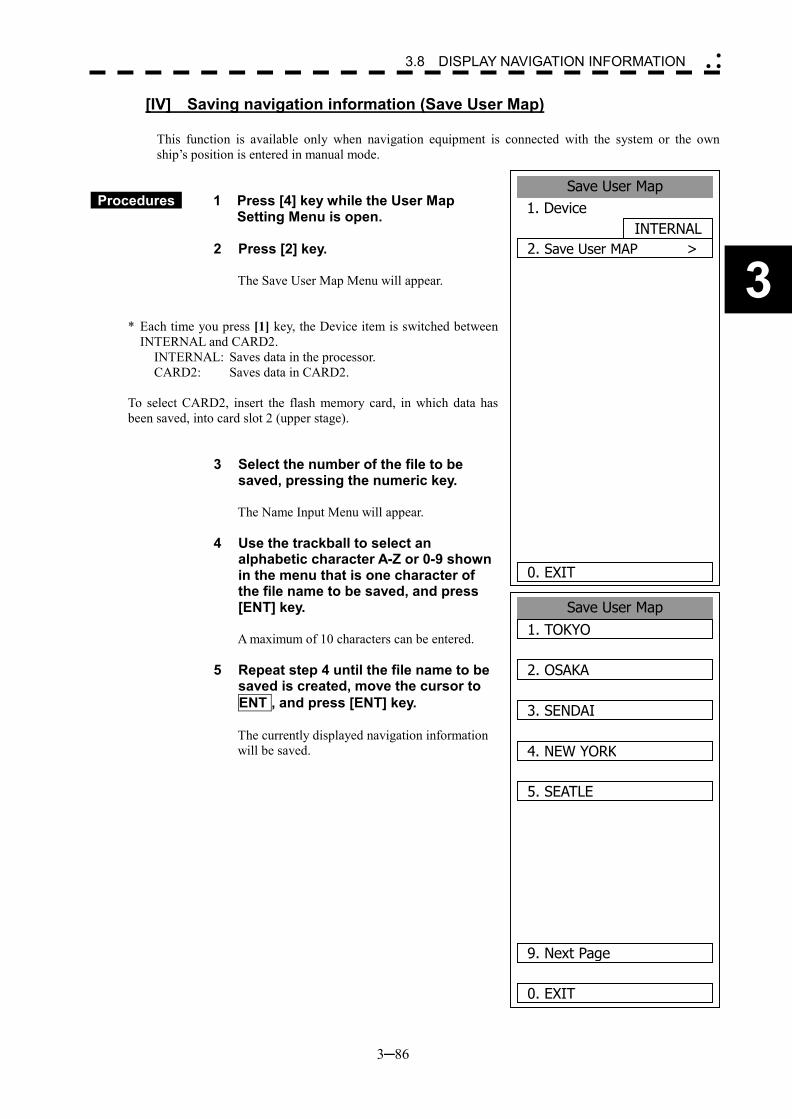
3─86
3
3.8 DISPLAY NAVIGATION INFORMATION �
� �
[IV] Saving navigation information (Save User Map)
This function is available only when navigation equipment is connected with the system or the own ship’s position is entered in manual mode.
Procedures 1 Press [4] key while the User Map Setting Menu is open.
2 Press [2] key.
The Save User Map Menu will appear.
* Each time you press [1] key, the Device item is switched between INTERNAL and CARD2.
INTERNAL: Saves data in the processor. CARD2: Saves data in CARD2.
To select CARD2, insert the flash memory card, in which data has been saved, into card slot 2 (upper stage).
3 Select the number of the file to be saved, pressing the numeric key.
The Name Input Menu will appear.
4 Use the trackball to select an alphabetic character A-Z or 0-9 shown in the menu that is one character of the file name to be saved, and press [ENT] key.
A maximum of 10 characters can be entered.
5 Repeat step 4 until the file name to be saved is created, move the cursor to ENT , and press [ENT] key.
The currently displayed navigation information will be saved.
Save User Map1. TOKYO
2. OSAKA
3. SENDAI
4. NEW YORK
5. SEATLE
9. Next Page
0. EXIT
Save User Map1. Device
INTERNAL2. Save User MAP >
0. EXIT
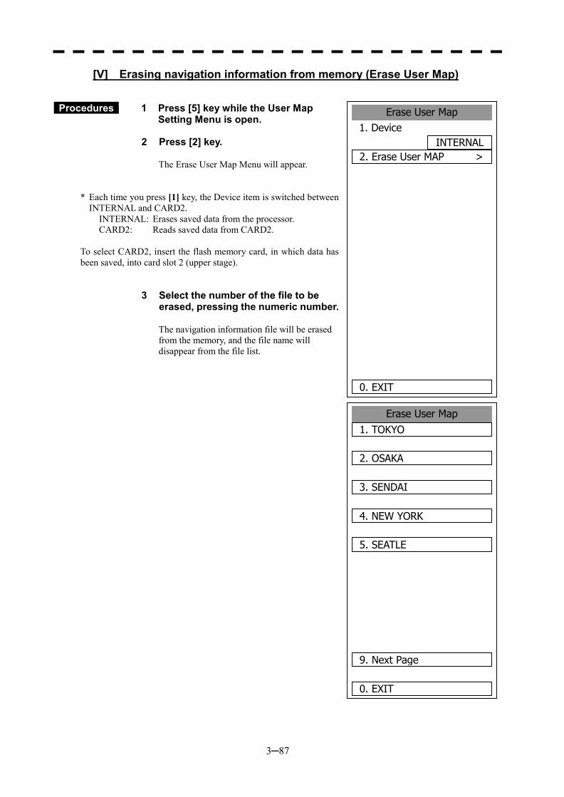
3─87
Erase User Map1. TOKYO
2. OSAKA
3. SENDAI
4. NEW YORK
5. SEATLE
9. Next Page
0. EXIT
[V] Erasing navigation information from memory (Erase User Map)
Procedures 1 Press [5] key while the User Map Setting Menu is open.
2 Press [2] key.
The Erase User Map Menu will appear.
* Each time you press [1] key, the Device item is switched between INTERNAL and CARD2.
INTERNAL: Erases saved data from the processor. CARD2: Reads saved data from CARD2.
To select CARD2, insert the flash memory card, in which data has been saved, into card slot 2 (upper stage).
3 Select the number of the file to be erased, pressing the numeric number.
The navigation information file will be erased from the memory, and the file name will disappear from the file list.
Erase User Map1. Device
INTERNAL2. Erase User MAP >
0. EXIT
3─88
3
3.8 DISPLAY NAVIGATION INFORMATION �
� �
[VII] Shifting the display position of navigation information to a correct
position (Shift)
If the display position of navigation information is incorrect, it can be shifted to the correct position in manual mode.
Procedures 1 Press [7] key while the User Map Setting Menu is open.
Shift will appear in the CURSOR mode field at the upper right of the radar display, and the navigation information shift mode is activated.
2 Use the trackball to move the pointer to a mark or a point on a NAV line, coastline, or depth contour line, and press [ENT] key.
3 Use the trackball to move the cross cursor mark to the position to which the mark or line is shifted, and press [ENT] key.
All the marks and lines currently displayed will be shifted to their correct positions.
6 Shifting the corrected display position of navigation information back to original (Shift Clear)
Procedures 1 Press [8] key while the User Map Setting Menu is open.
Only the latest display position correction information (for a single operation) will be cleared, and the navigation information is displayed at the original position.
Note: Only the latest correction information is cleared, and correction information older than that cannot be cleared any more.
Once operation such as creation, move, deletion, insertion, or batch deletion is done after the
correction of a navigation information display position, the latest correction information cannot be restored to original any more.
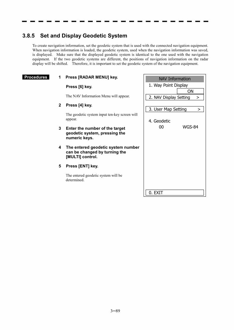
3─89
3.8.5 Set and Display Geodetic System
To create navigation information, set the geodetic system that is used with the connected navigation equipment. When navigation information is loaded, the geodetic system, used when the navigation information was saved, is displayed. Make sure that the displayed geodetic system is identical to the one used with the navigation equipment. If the two geodetic systems are different, the positions of navigation information on the radar display will be shifted. Therefore, it is important to set the geodetic system of the navigation equipment.
Procedures 1 Press [RADAR MENU] key.
Press [6] key.
The NAV Information Menu will appear.
2 Press [4] key.
The geodetic system input ten-key screen will appear.
3 Enter the number of the target geodetic system, pressing the numeric keys.
4 The entered geodetic system number
can be changed by turning the [MULTI] control.
5 Press [ENT] key.
The entered geodetic system will be determined.
NAV Information1. Way Point Display
ON2. NAV Display Setting >
3. User Map Setting >
4. GeodeticWGS-8400
0. EXIT
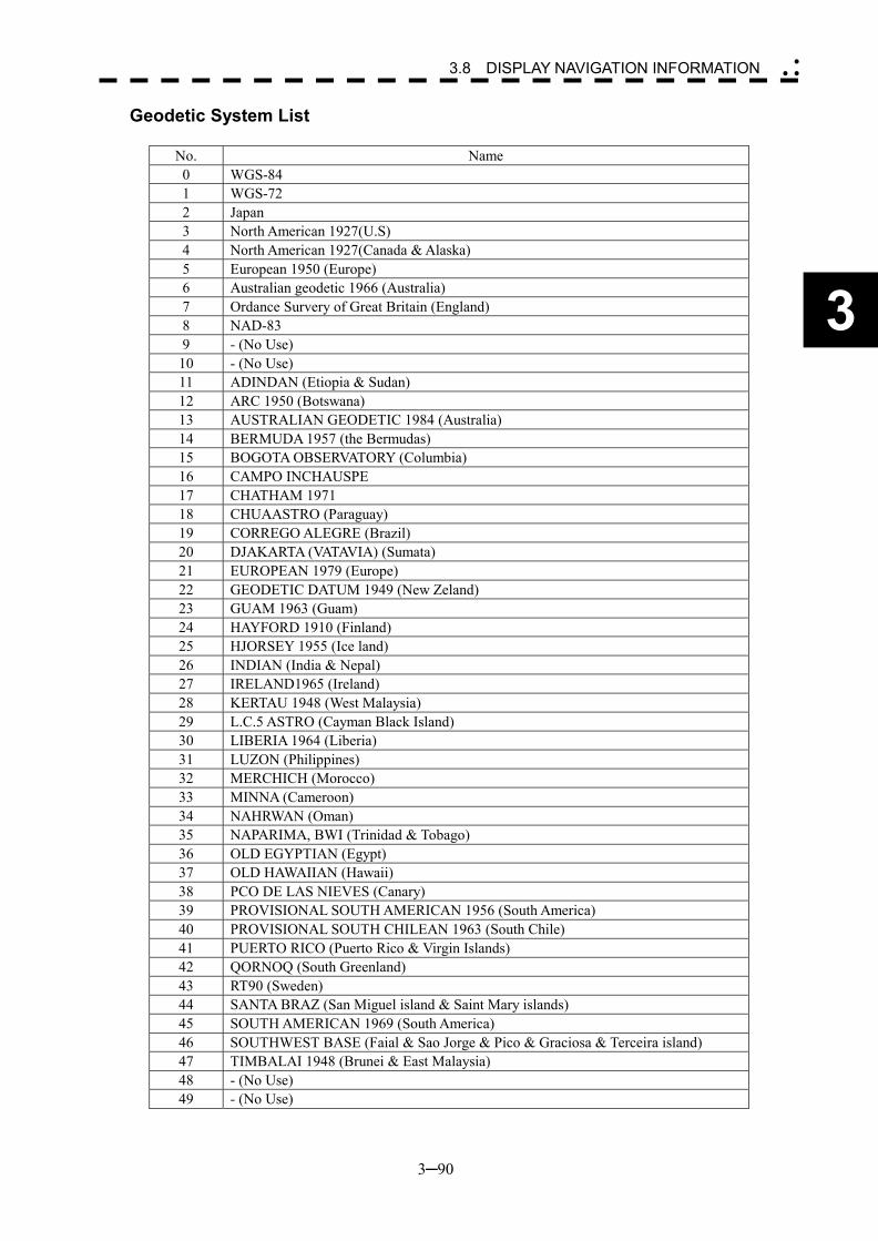
3─90
3
3.8 DISPLAY NAVIGATION INFORMATION �
� �
Geodetic System List
No. Name 0 WGS-84 1 WGS-72 2 Japan 3 North American 1927(U.S) 4 North American 1927(Canada & Alaska) 5 European 1950 (Europe) 6 Australian geodetic 1966 (Australia) 7 Ordance Survery of Great Britain (England) 8 NAD-83 9 - (No Use)
10 - (No Use) 11 ADINDAN (Etiopia & Sudan) 12 ARC 1950 (Botswana) 13 AUSTRALIAN GEODETIC 1984 (Australia) 14 BERMUDA 1957 (the Bermudas) 15 BOGOTA OBSERVATORY (Columbia) 16 CAMPO INCHAUSPE 17 CHATHAM 1971 18 CHUAASTRO (Paraguay) 19 CORREGO ALEGRE (Brazil) 20 DJAKARTA (VATAVIA) (Sumata) 21 EUROPEAN 1979 (Europe) 22 GEODETIC DATUM 1949 (New Zeland) 23 GUAM 1963 (Guam) 24 HAYFORD 1910 (Finland) 25 HJORSEY 1955 (Ice land) 26 INDIAN (India & Nepal) 27 IRELAND1965 (Ireland) 28 KERTAU 1948 (West Malaysia) 29 L.C.5 ASTRO (Cayman Black Island) 30 LIBERIA 1964 (Liberia) 31 LUZON (Philippines) 32 MERCHICH (Morocco) 33 MINNA (Cameroon) 34 NAHRWAN (Oman) 35 NAPARIMA, BWI (Trinidad & Tobago) 36 OLD EGYPTIAN (Egypt) 37 OLD HAWAIIAN (Hawaii) 38 PCO DE LAS NIEVES (Canary) 39 PROVISIONAL SOUTH AMERICAN 1956 (South America) 40 PROVISIONAL SOUTH CHILEAN 1963 (South Chile) 41 PUERTO RICO (Puerto Rico & Virgin Islands) 42 QORNOQ (South Greenland) 43 RT90 (Sweden) 44 SANTA BRAZ (San Miguel island & Saint Mary islands) 45 SOUTH AMERICAN 1969 (South America) 46 SOUTHWEST BASE (Faial & Sao Jorge & Pico & Graciosa & Terceira island) 47 TIMBALAI 1948 (Brunei & East Malaysia) 48 - (No Use) 49 - (No Use)
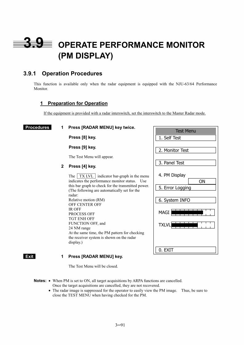
3─91
3.9 OPERATE PERFORMANCE MONITOR (PM DISPLAY)
3.9.1 Operation Procedures
This function is available only when the radar equipment is equipped with the NJU-63/64 Performance Monitor.
1 Preparation for Operation
If the equipment is provided with a radar interswitch, set the interswitch to the Master Radar mode.
Procedures 1 Press [RADAR MENU] key twice. Press [8] key. Press [9] key.
The Test Menu will appear.
2 Press [4] key. The TX LVL indicator bar-graph in the menu indicates the performance monitor status. Use this bar graph to check for the transmitted power. (The following are automatically set for the radar: Relative motion (RM) OFF CENTER OFF IR OFF PROCESS OFF TGT ENH OFF FUNCTION OFF, and 24 NM range At the same time, the PM pattern for checking the receiver system is shown on the radar display.)
Exit 1 Press [RADAR MENU] key.
The Test Menu will be closed.
Notes: � When PM is set to ON, all target acquisitions by ARPA functions are cancelled. Once the target acquisitions are cancelled, they are not recovered. � The radar image is suppressed for the operator to easily view the PM image. Thus, be sure to
close the TEST MENU when having checked for the PM.
Test Menu1. Self Test
2. Monitor Test
3. Panel Test
4. PM DisplayON
5. Error Logging
6. System INFO
MAGI
TXLVL
0. EXIT
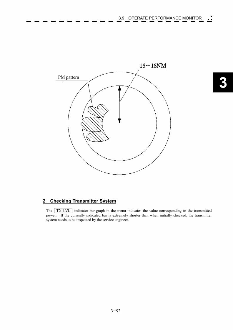
3─92
3
3.9 OPERATE PERFORMANCE MONITOR �
� �
2 Checking Transmitter System
The TX LVL indicator bar-graph in the menu indicates the value corresponding to the transmitted power. If the currently indicated bar is extremely shorter than when initially checked, the transmitter system needs to be inspected by the service engineer.
PM pattern
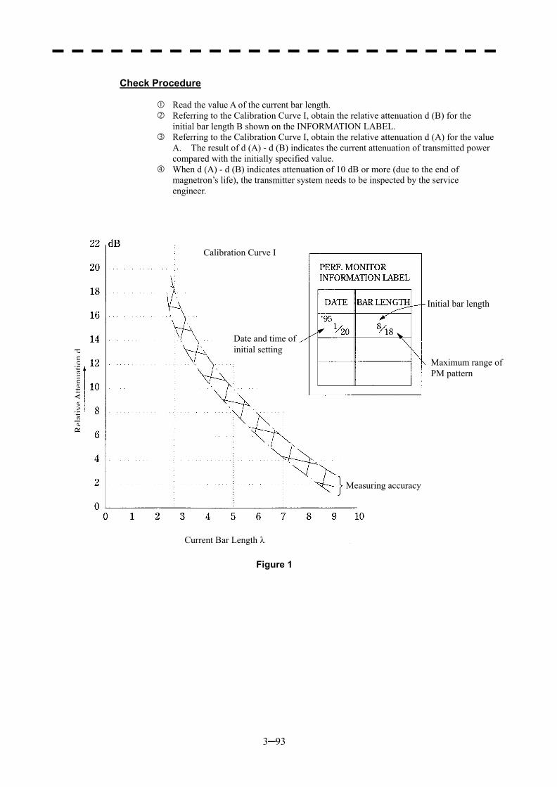
3─93
Check Procedure
� Read the value A of the current bar length. � Referring to the Calibration Curve I, obtain the relative attenuation d (B) for the
initial bar length B shown on the INFORMATION LABEL. � Referring to the Calibration Curve I, obtain the relative attenuation d (A) for the value
A. The result of d (A) - d (B) indicates the current attenuation of transmitted power compared with the initially specified value.
� When d (A) - d (B) indicates attenuation of 10 dB or more (due to the end of magnetron’s life), the transmitter system needs to be inspected by the service engineer.
Figure 1
Calibration Curve I
Rel
ativ
eAtte
nuat
ion
d
Date and time of initial setting
Initial bar length
Maximum range of PM pattern
Measuring accuracy
Current Bar Length �
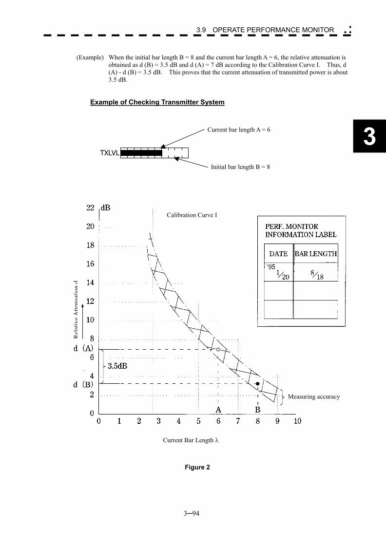
3─94
3
3.9 OPERATE PERFORMANCE MONITOR �
� �
(Example) When the initial bar length B = 8 and the current bar length A = 6, the relative attenuation is
obtained as d (B) = 3.5 dB and d (A) = 7 dB according to the Calibration Curve I. Thus, d (A) - d (B) = 3.5 dB. This proves that the current attenuation of transmitted power is about 3.5 dB.
Example of Checking Transmitter System
Figure 2
TXLVL
Current bar length A = 6
Initial bar length B = 8
Calibration Curve I
Rel
ativ
eAtte
nuat
ion
d
Measuring accuracy
Current Bar Length �
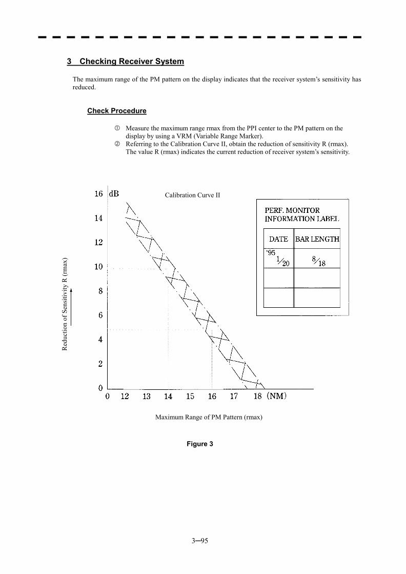
3─95
3 Checking Receiver System
The maximum range of the PM pattern on the display indicates that the receiver system’s sensitivity has reduced.
Check Procedure
� Measure the maximum range rmax from the PPI center to the PM pattern on the display by using a VRM (Variable Range Marker).
� Referring to the Calibration Curve II, obtain the reduction of sensitivity R (rmax). The value R (rmax) indicates the current reduction of receiver system’s sensitivity.
Figure 3
Calibration Curve II
Red
uctio
n of
Sen
sitiv
ity R
(rm
ax)
Maximum Range of PM Pattern (rmax)
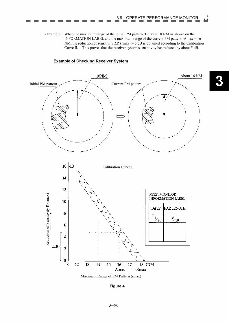
3─96
3
3.9 OPERATE PERFORMANCE MONITOR �
� �
(Example) When the maximum range of the initial PM pattern rBmax = 18 NM as shown on the
INFORMATION LABEL and the maximum range of the current PM pattern rAmax = 16 NM, the reduction of sensitivity �R (rmax) = 5 dB is obtained according to the Calibration Curve II. This proves that the receiver system’s sensitivity has reduced by about 5 dB.
Example of Checking Receiver System
Figure 4
Calibration Curve II
Red
uctio
n of
Sen
sitiv
ity R
(rm
ax)
Maximum Range of PM Pattern (rmax)
Initial PM pattern Current PM pattern
About 16 NM
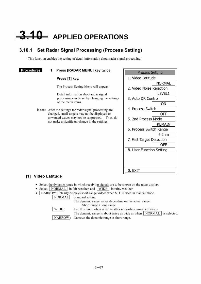
3─97
3.10 APPLIED OPERATIONS 3.10.1 Set Radar Signal Processing (Process Setting)
This function enables the setting of detail information about radar signal processing.
Procedures 1 Press [RADAR MENU] key twice. Press [1] key.
The Process Setting Menu will appear. Detail information about radar signal processing can be set by changing the settings of the menu items.
Note: After the settings for radar signal processing are changed, small targets may not be displayed or unwanted waves may not be suppressed. Thus, do not make a significant change in the settings.
[1] Video Latitude
�� Select the dynamic range in which receiving signals are to be shown on the radar display. �� Select NORMAL in fair weather, and WIDE in rainy weather. �� NARROW clearly displays short-range videos when STC is used in manual mode.
NORMAL : Standard setting The dynamic range varies depending on the actual range: Short range > long range WIDE : Use this mode when rainy weather intensifies unwanted waves. The dynamic range is about twice as wide as when NORMAL is selected. NARROW : Narrows the dynamic range at short range.
Process Setting1. Video Latitude
NORMAL2. Video Noise Rejection
LEVEL13. Auto DR Control
ON4. Process Switch
OFF5. 2nd Process Mode
REMAIN6. Process Switch Range
6.2nm7. Fast Target Detection
OFF8. User Function Setting
0. EXIT
3─98
3
3.10 APPLIED OPERATIONS �
� �
[2] Video Noise Rejection
�� This function rejects signals that assumed as noise and clutter in radar videos. �� Select OFF to display radar videos like analog signals. �� Select LEVEL1 or LEVEL2 to suppress noise and clutter. �� Select LEVEL1 or LEVEL2 to superimpose-display the chart.
OFF : Turns off the noise rejection function, and displays all signals. Targets are popped up from noise and displayed like analog signals. LEVEL1 : Rejects the signals of definitely unwanted waves (noise and clutter). When detection of targets or unwanted waves is not definite, the signals are
displayed. When detection of targets is definite, the signals are displayed. LEVEL2 : Rejects the signals of definitely unwanted waves (noise and clutter). When detection of targets or unwanted waves is not definite, the signals are
rejected. Only when detection of targets is definite, the signals are displayed.
[3] Auto DR Control
�� This function automatically controls the dynamic range of radar videos when the AUTO SEA/RAIN clutter suppression mode is used.
�� When the AUTO SEA clutter suppression mode is used, this function improves sensitivity by widening the dynamic range of only areas where sea clutter is strong and narrowing the dynamic range of areas where sea clutter is not detected.
�� When the AUTO RAIN clutter suppression mode is used, this function improves sensitivity by widening the dynamic range of areas where sea clutter or rain/snow clutter is strong and narrowing the dynamic range of the other areas.
�� Land videos become obscure when the AUTO RAIN clutter suppression mode is used. OFF : Does not control the dynamic range automatically. The dynamic range is set in the same manner as when the MANUAL
SEA/RAIN clutter suppression mode is used. ON : Automatically controls the dynamic range. (Standard setting)
[4] Process Switch
�� This function sets a specific area and switches the video process mode between the inside and outside of the area.
�� In [5] 2nd Process Mode, set the second video process mode for the area outside the boundary. �� In [2] PROCESS of Main Menu , set the first video process mode for the area inside the boundary. �� Sensitivity at a distance can be improved by suppressing near sea clutter through the correlative
process. �� There are two methods for setting an area:
OFF : Disables the Process Switching function. (Standard setting) RANGE FIX : Sets a boundary at a constant range from the center. Set the boundary range in [6] Process Switch Range. The specific area turns out to be a circle with the own ship’s position as
the center. AUTO : Automatically sets a specific area. The area subject to many clutter returns is inside the boundary, and the
area less subject to clutter returns is outside the boundary.
3─99
[5] 2nd Process Mode
�� Set the second video process mode for the outside of a specific area. �� This function is enabled when RANGE FIX or AUTO is selected in [4] Process Switching.
Video process modes PROC OFF Video process off: Select this mode in general. 3SCAN CORR Correlative process 1: Select this mode when many rain/snow clutter returns are
detected. 4SCAN CORR Correlative process 2: Select this mode to highlight targets while suppressing sea
clutter returns. 5SCAN CORR Correlative process 3: Select this mode to detect small targets hidden by sea clutter
returns. REMAIN Video process 4: Select this mode when own ship yaws wildly. PEAK HOLD Video process 5: Select this mode to detect small targets of which detection
probability is low.
[6] Process Switch Range
�� Set the boundary range of a specific area. �� This function is enabled when RANGE FIX is selected in [4] Process Switch. �� The specific area turns out to be a circle with the own ship’s position as the center. �� The boundary range can be set in units of 0.1 nm, ranging 0.1 to 25.5 nm. �� After selecting PROC Switch Range, adjust the range using the [VRM] control. �� When finishing the adjustment, press [ENT] key to determine the video process switching range.
[7] Fast Target Detection
�� This function displays fast moving targets that are suppressed in scan-correlative process mode. �� This function is enabled when 3SCAN CORR , 4SCAN CORR , or 5SCAN CORR is selected
as the video process mode. �� If unwanted waves remain on the radar display, suppress them by using the [SEA], [RAIN], or
[GAIN] control, or adjusting the interference rejection mode. OFF : Disables the Fast Target Detection function. ON : Enables the Fast Target Detection function.
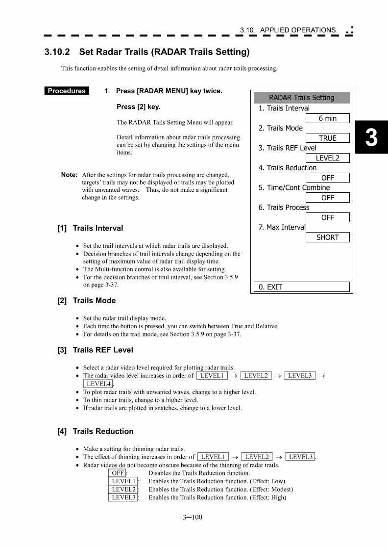
3─100
3
3.10 APPLIED OPERATIONS �
� �
3.10.2 Set Radar Trails (RADAR Trails Setting)
This function enables the setting of detail information about radar trails processing.
Procedures 1 Press [RADAR MENU] key twice. Press [2] key.
The RADAR Tails Setting Menu will appear.
Detail information about radar trails processing can be set by changing the settings of the menu items.
Note: After the settings for radar trails processing are changed, targets’ trails may not be displayed or trails may be plotted with unwanted waves. Thus, do not make a significant change in the settings.
[1] Trails Interval
�� Set the trail intervals at which radar trails are displayed. �� Decision branches of trail intervals change depending on the
setting of maximum value of radar trail display time. �� The Multi-function control is also available for setting. �� For the decision branches of trail interval, see Section 3.5.9
on page 3-37.
[2] Trails Mode
�� Set the radar trail display mode. �� Each time the button is pressed, you can switch between True and Relative. �� For details on the trail mode, see Section 3.5.9 on page 3-37.
[3] Trails REF Level
�� Select a radar video level required for plotting radar trails. �� The radar video level increases in order of LEVEL1 � LEVEL2 � LEVEL3 �
LEVEL4 . �� To plot radar trails with unwanted waves, change to a higher level. �� To thin radar trails, change to a higher level. �� If radar trails are plotted in snatches, change to a lower level.
[4] Trails Reduction
�� Make a setting for thinning radar trails. �� The effect of thinning increases in order of LEVEL1 � LEVEL2 � LEVEL3 . �� Radar videos do not become obscure because of the thinning of radar trails.
OFF : Disables the Trails Reduction function. LEVEL1 : Enables the Trails Reduction function. (Effect: Low) LEVEL2 : Enables the Trails Reduction function. (Effect: Modest) LEVEL3 : Enables the Trails Reduction function. (Effect: High)
RADAR Trails Setting1. Trails Interval
6 min2. Trails Mode
TRUE3. Trails REF Level
LEVEL24. Trails Reduction
OFF5. Time/Cont Combine
OFF6. Trails Process
OFF7. Max Interval
SHORT
0. EXIT
3─101
[5] Time/Cont Combine
�� This function superimpose-displays time radar trails and continuous radar trails. �� Operators can distinguish time radar trails from continuous radar trails by setting different colors for
both types of trails. OFF : Disables the Time/Cont Combine function. ON : Enables the Time/Cont Combine function.
[6] Trails Process
�� Determine whether to use the video process with radar signals for plotting radar trails. �� When Trails Process is ON , radar trails are never plotted with unwanted waves, but the radar trails
of fast moving targets may not be plotted. �� When Trails Process is OFF , radar trails may be plotted with unwanted waves, but the radar trails of
fast moving targets are always plotted. OFF : Disables the Trails Process function. ON : Enables the Trails Process function.
[7] MAX Interval
�� Select the maximum time for displaying radar trails. �� Select SHORT when short radar trails are often used in bays and the likes. �� Select LONG when long radar trails are necessary for ocean navigation. �� MEDIUM is for specification between SHORT and LONG . �� Continuous trails are available with all the options.
SHORT : Sets 15 minutes as the maximum time for radar trails display. MEDIUM : Sets 30 minutes as the maximum time for radar trails display. LONG : Sets 60 minutes as the maximum time for radar trails display. SUPER LONG : Sets 12 hours as the maximum time for radar trails display.
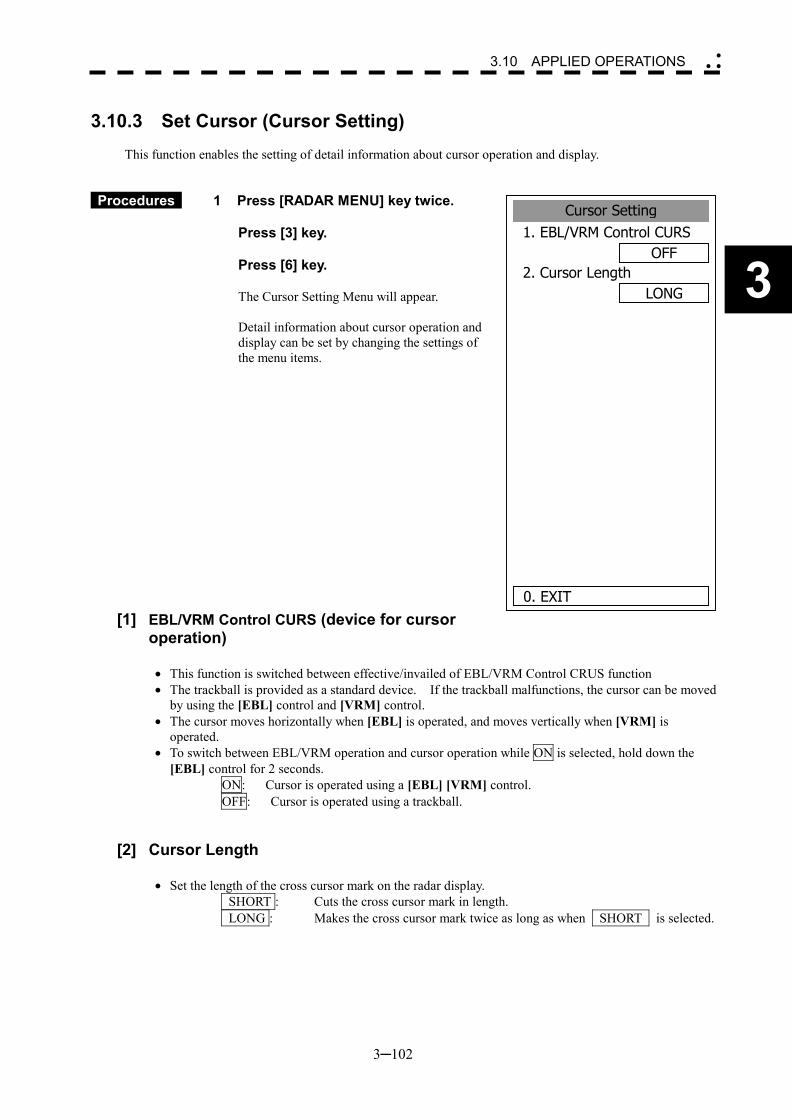
3─102
3
3.10 APPLIED OPERATIONS �
� �
3.10.3 Set Cursor (Cursor Setting)
This function enables the setting of detail information about cursor operation and display.
Procedures 1 Press [RADAR MENU] key twice. Press [3] key. Press [6] key.
The Cursor Setting Menu will appear.
Detail information about cursor operation and display can be set by changing the settings of the menu items.
[1] EBL/VRM Control CURS (device for cursor operation)
�� This function is switched between effective/invailed of EBL/VRM Control CRUS function �� The trackball is provided as a standard device. If the trackball malfunctions, the cursor can be moved
by using the [EBL] control and [VRM] control. �� The cursor moves horizontally when [EBL] is operated, and moves vertically when [VRM] is
operated. �� To switch between EBL/VRM operation and cursor operation while ON is selected, hold down the
[EBL] control for 2 seconds. ON: Cursor is operated using a [EBL] [VRM] control. OFF: Cursor is operated using a trackball.
[2] Cursor Length
�� Set the length of the cross cursor mark on the radar display. SHORT : Cuts the cross cursor mark in length. LONG : Makes the cross cursor mark twice as long as when SHORT is selected.
Cursor Setting1. EBL/VRM Control CURS
OFF2. Cursor Length
LONG
0. EXIT
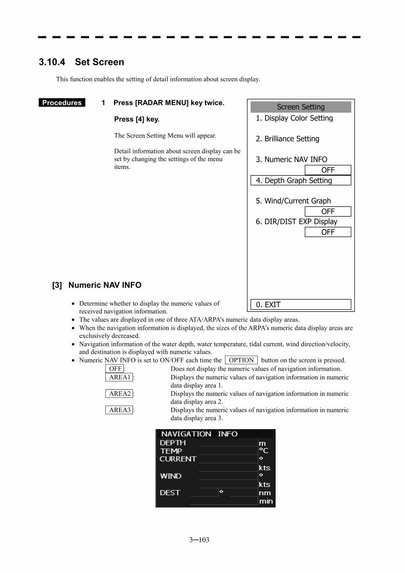
3─103
3.10.4 Set Screen
This function enables the setting of detail information about screen display.
Procedures 1 Press [RADAR MENU] key twice. Press [4] key.
The Screen Setting Menu will appear.
Detail information about screen display can be set by changing the settings of the menu items.
[3] Numeric NAV INFO
�� Determine whether to display the numeric values of received navigation information.
�� The values are displayed in one of three ATA/ARPA’s numeric data display areas. �� When the navigation information is displayed, the sizes of the ARPA’s numeric data display areas are
exclusively decreased. �� Navigation information of the water depth, water temperature, tidal current, wind direction/velocity,
and destination is displayed with numeric values. �� Numeric NAV INFO is set to ON/OFF each time the OPTION button on the screen is pressed.
OFF : Does not display the numeric values of navigation information. AREA1 : Displays the numeric values of navigation information in numeric
data display area 1. AREA2 : Displays the numeric values of navigation information in numeric
data display area 2. AREA3 : Displays the numeric values of navigation information in numeric
data display area 3.
Screen Setting1. Display Color Setting
2. Brilliance Setting
3. Numeric NAV INFOOFF
4. Depth Graph Setting
5. Wind/Current GraphOFF
6. DIR/DIST EXP DisplayOFF
0. EXIT
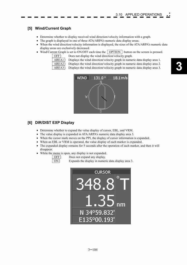
3─104
3
3.10 APPLIED OPERATIONS �
� �
[5] Wind/Current Graph
�� Determine whether to display received wind direction/velocity information with a graph. �� The graph is displayed in one of three ATA/ARPA’s numeric data display areas. �� When the wind direction/velocity information is displayed, the sizes of the ATA/ARPA’s numeric data
display areas are exclusively decreased. �� Wind/Current Graph is set to ON/OFF each time the OPTION button on the screen is pressed.
OFF : Does not display the wind direction/velocity graph. AREA1 : Displays the wind direction/velocity graph in numeric data display area 1. AREA2 : Displays the wind direction/velocity graph in numeric data display area 2. AREA3 : Displays the wind direction/velocity graph in numeric data display area 3.
[6] DIR/DIST EXP Display
�� Determine whether to expand the value display of cursor, EBL, and VRM. �� The value display is expanded in ATA/ARPA’s numeric data display area 3. �� When the cursor mark moves on the PPI, the display of cursor information is expanded. �� When an EBL or VRM is operated, the value display of each marker is expanded. �� The expanded display remains for 5 seconds after the operation of each marker, and then it will
disappear. �� While the menu is open, any display is not expanded.
OFF : Does not expand any display. ON : Expands the display in numeric data display area 3.
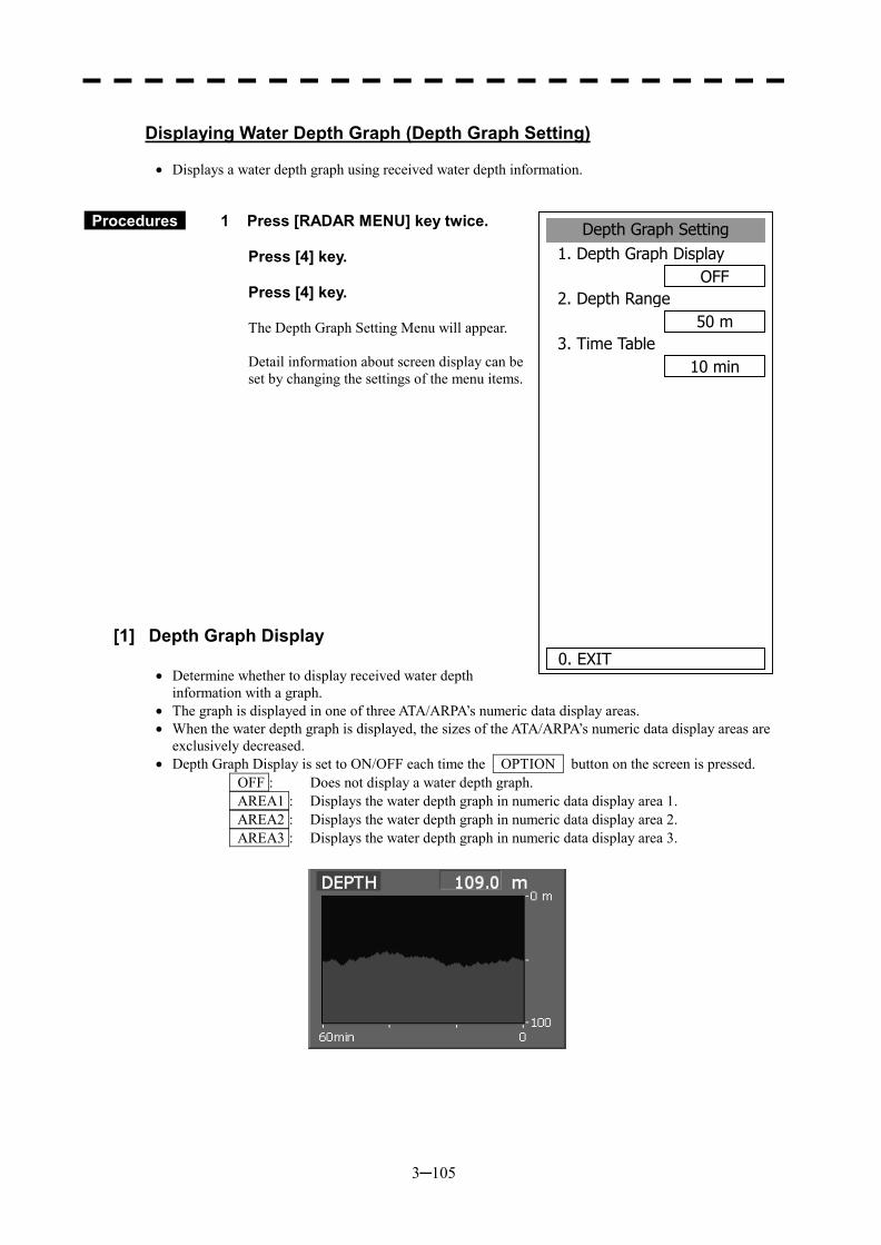
3─105
Displaying Water Depth Graph (Depth Graph Setting)
�� Displays a water depth graph using received water depth information.
Procedures 1 Press [RADAR MENU] key twice. Press [4] key. Press [4] key.
The Depth Graph Setting Menu will appear.
Detail information about screen display can be set by changing the settings of the menu items.
[1] Depth Graph Display
�� Determine whether to display received water depth information with a graph.
�� The graph is displayed in one of three ATA/ARPA’s numeric data display areas. �� When the water depth graph is displayed, the sizes of the ATA/ARPA’s numeric data display areas are
exclusively decreased. �� Depth Graph Display is set to ON/OFF each time the OPTION button on the screen is pressed.
OFF : Does not display a water depth graph. AREA1 : Displays the water depth graph in numeric data display area 1. AREA2 : Displays the water depth graph in numeric data display area 2. AREA3 : Displays the water depth graph in numeric data display area 3.
Depth Graph Setting1. Depth Graph Display
OFF2. Depth Range
50 m3. Time Table
10 min
0. EXIT
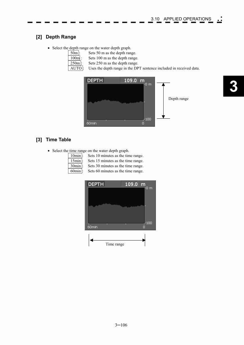
3─106
3
3.10 APPLIED OPERATIONS �
� �
[2] Depth Range
�� Select the depth range on the water depth graph. 50m : Sets 50 m as the depth range. 100m : Sets 100 m as the depth range. 250m : Sets 250 m as the depth range. AUTO : Uses the depth range in the DPT sentence included in received data.
[3] Time Table
�� Select the time range on the water depth graph. 10min : Sets 10 minutes as the time range. 15min : Sets 15 minutes as the time range. 30min : Sets 30 minutes as the time range. 60min : Sets 60 minutes as the time range.
Depth range
Time range
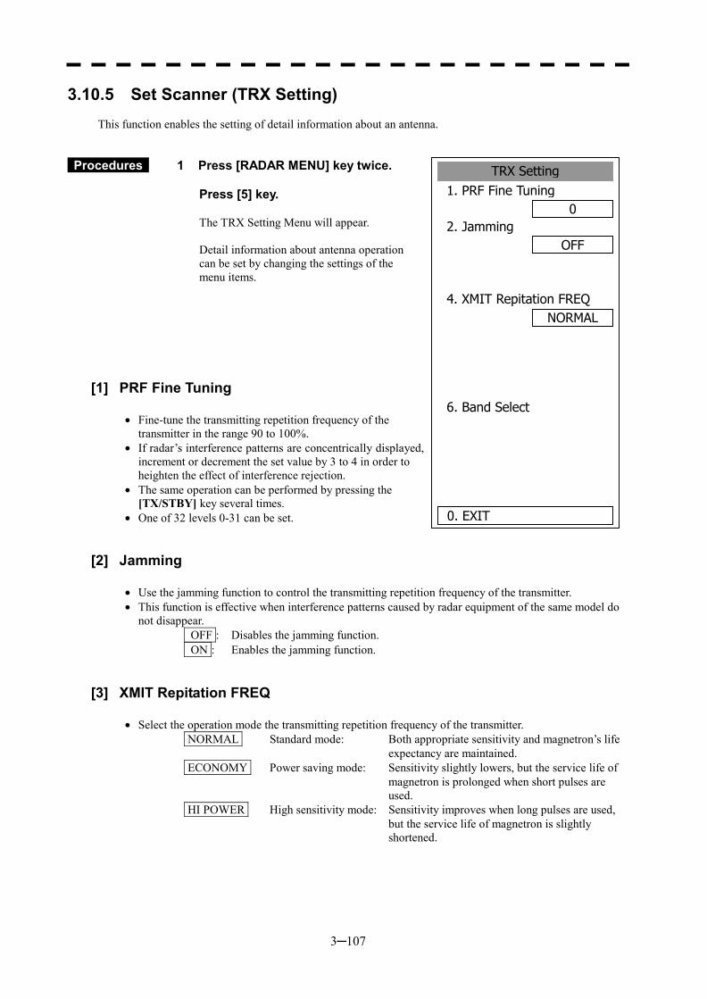
3─107
3.10.5 Set Scanner (TRX Setting)
This function enables the setting of detail information about an antenna.
Procedures 1 Press [RADAR MENU] key twice. Press [5] key.
The TRX Setting Menu will appear.
Detail information about antenna operation can be set by changing the settings of the menu items.
[1] PRF Fine Tuning
�� Fine-tune the transmitting repetition frequency of the transmitter in the range 90 to 100%.
�� If radar’s interference patterns are concentrically displayed, increment or decrement the set value by 3 to 4 in order to heighten the effect of interference rejection.
�� The same operation can be performed by pressing the [TX/STBY] key several times.
�� One of 32 levels 0-31 can be set.
[2] Jamming
�� Use the jamming function to control the transmitting repetition frequency of the transmitter. �� This function is effective when interference patterns caused by radar equipment of the same model do
not disappear. OFF : Disables the jamming function. ON : Enables the jamming function.
[3] XMIT Repitation FREQ
�� Select the operation mode the transmitting repetition frequency of the transmitter. NORMAL Standard mode: Both appropriate sensitivity and magnetron’s life
expectancy are maintained. ECONOMY Power saving mode: Sensitivity slightly lowers, but the service life of
magnetron is prolonged when short pulses are used.
HI POWER High sensitivity mode: Sensitivity improves when long pulses are used, but the service life of magnetron is slightly shortened.
TRX Setting1. PRF Fine Tuning
02. Jamming
OFF
4. XMIT Repitation FREQ
6. Band Select
0. EXIT
NORMAL

3─108
3
3.10 APPLIED OPERATIONS �
� �
[6] Band Select
�� Select band of antenna. This item is effective only when the antenna in connection supports two frequencies.
X-Band : Selects the X-band side from the two frequencies. S-Band : Selects the S-band side from the two frequencies. X/S-band : Supports the two frequencies.
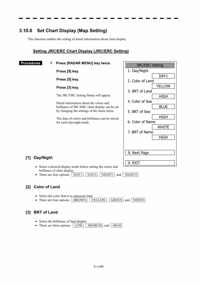
3─109
3.10.6 Set Chart Display (Map Setting)
This function enables the setting of detail information about chart display.
Setting JRC/ERC Chart Display (JRC/ERC Setting)
Procedures 1 Press [RADAR MENU] key twice. Press [9] key. Press [5] key. Press [3] key.
The JRC/ERC Setting Menu will appear.
Detail information about the colors and brilliance of JRC/ERC chart display can be set by changing the settings of the menu items.
The data of colors and brilliance can be stored for each day/night mode.
[1] Day/Night
�� Select a desired display mode before setting the colors and brilliance of chart display.
�� There are four options: DAY1 , DAY2 , NIGHT1 , and NIGHT2 .
[2] Color of Land
�� Select the color that is to represent land. �� There are four options: BROWN , YELLOW , GREEN , and WHITE .
[3] BRT of Land
�� Select the brilliance of land display. �� There are three options: LOW , MEDIUM , and HIGH .
JRC/ERC Setting1. Day/Night
DAY12. Color of Land
YELLOW3. BRT of Land
HIGH4. Color of Sea
BLUE5. BRT of Sea
HIGH6. Color of Name
WHITE7. BRT of Name
HIGH
9. Next Page
0. EXIT
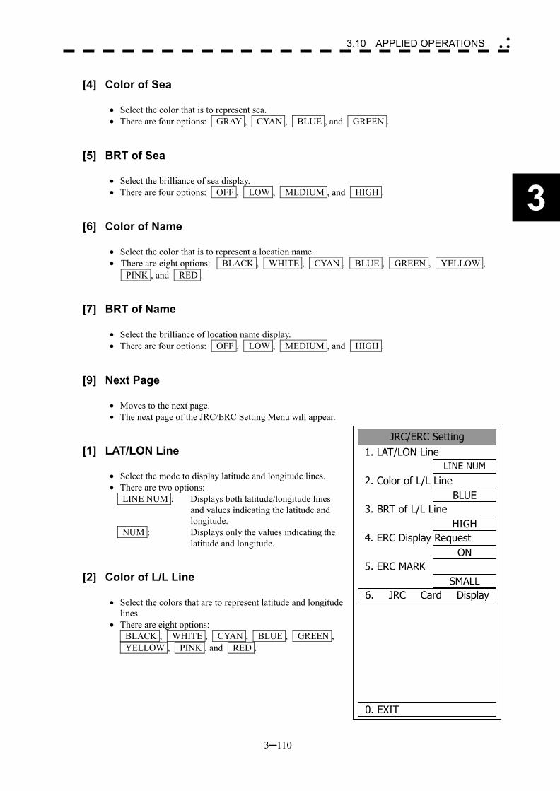
3─110
3
3.10 APPLIED OPERATIONS �
� �
[4] Color of Sea
�� Select the color that is to represent sea. �� There are four options: GRAY , CYAN , BLUE , and GREEN .
[5] BRT of Sea
�� Select the brilliance of sea display. �� There are four options: OFF , LOW , MEDIUM , and HIGH .
[6] Color of Name
�� Select the color that is to represent a location name. �� There are eight options: BLACK , WHITE , CYAN , BLUE , GREEN , YELLOW ,
PINK , and RED .
[7] BRT of Name
�� Select the brilliance of location name display. �� There are four options: OFF , LOW , MEDIUM , and HIGH .
[9] Next Page
�� Moves to the next page. �� The next page of the JRC/ERC Setting Menu will appear.
[1] LAT/LON Line
�� Select the mode to display latitude and longitude lines. �� There are two options:
LINE NUM : Displays both latitude/longitude lines and values indicating the latitude and longitude.
NUM : Displays only the values indicating the latitude and longitude.
[2] Color of L/L Line
�� Select the colors that are to represent latitude and longitude lines.
�� There are eight options: BLACK , WHITE , CYAN , BLUE , GREEN , YELLOW , PINK , and RED .
JRC/ERC Setting1. LAT/LON Line
LINE NUM
2. Color of L/L LineBLUE
3. BRT of L/L LineHIGH
4. ERC Display RequestON
5. ERC MARKSMALL
6. JRC Card Display
0. EXIT
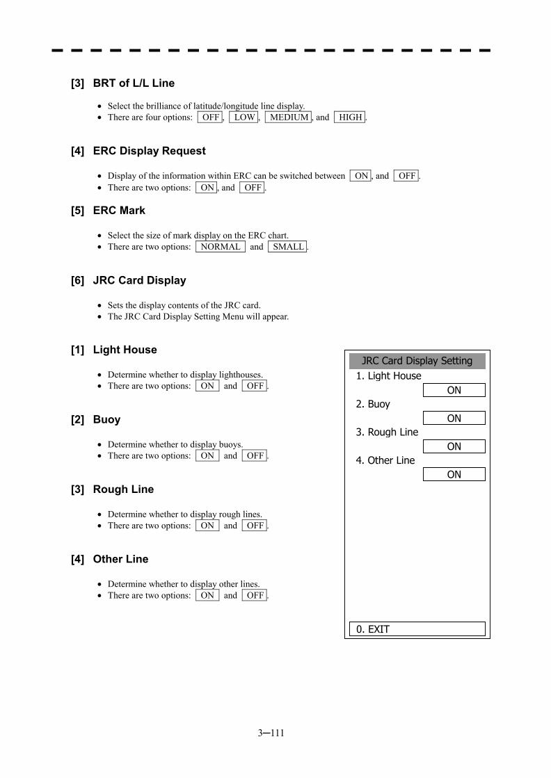
3─111
[3] BRT of L/L Line
�� Select the brilliance of latitude/longitude line display. �� There are four options: OFF , LOW , MEDIUM , and HIGH .
[4] ERC Display Request
�� Display of the information within ERC can be switched between ON , and OFF . �� There are two options: ON , and OFF .
[5] ERC Mark
�� Select the size of mark display on the ERC chart. �� There are two options: NORMAL and SMALL .
[6] JRC Card Display
�� Sets the display contents of the JRC card. �� The JRC Card Display Setting Menu will appear.
[1] Light House
�� Determine whether to display lighthouses. �� There are two options: ON and OFF .
[2] Buoy
�� Determine whether to display buoys. �� There are two options: ON and OFF .
[3] Rough Line
�� Determine whether to display rough lines. �� There are two options: ON and OFF .
[4] Other Line
�� Determine whether to display other lines. �� There are two options: ON and OFF .
JRC Card Display Setting1. Light House
ON2. Buoy
ON3. Rough Line
ON4. Other Line
ON
0. EXIT
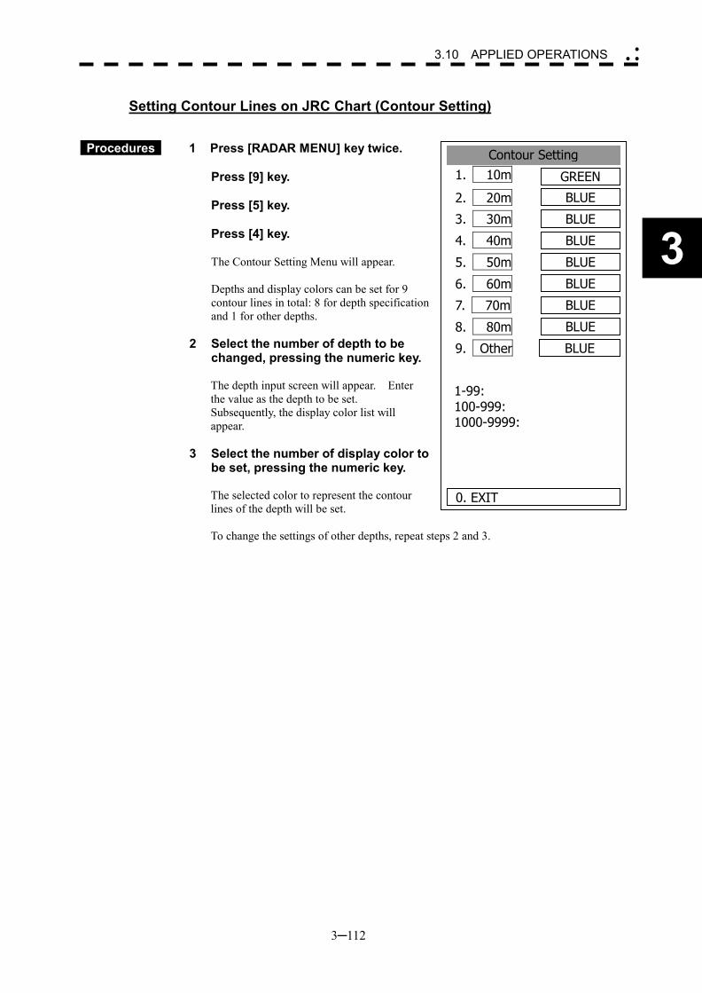
3─112
3
3.10 APPLIED OPERATIONS �
� �
Setting Contour Lines on JRC Chart (Contour Setting)
Procedures 1 Press [RADAR MENU] key twice. Press [9] key. Press [5] key. Press [4] key.
The Contour Setting Menu will appear.
Depths and display colors can be set for 9 contour lines in total: 8 for depth specification and 1 for other depths.
2 Select the number of depth to be
changed, pressing the numeric key. The depth input screen will appear. Enter the value as the depth to be set. Subsequently, the display color list will appear.
3 Select the number of display color to be set, pressing the numeric key. The selected color to represent the contour lines of the depth will be set. To change the settings of other depths, repeat steps 2 and 3.
Contour Setting1. 10m GREEN
2. 20m BLUE
3. 30m BLUE
4. 40m BLUE
5. 50m BLUE
6. 60m BLUE
7. 70m BLUE
8. 80m BLUE
9. Other BLUE
0. EXIT
1-99: 100-999: 1000-9999:
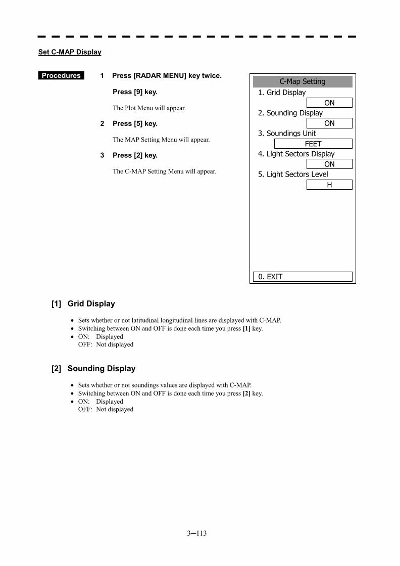
3─113
C-Map Setting1. Grid Display
ON2. Sounding Display
ON3. Soundings Unit
FEET4. Light Sectors Display
ON5. Light Sectors Level
H
0. EXIT
Set C-MAP Display
Procedures 1 Press [RADAR MENU] key twice.
Press [9] key.
The Plot Menu will appear.
2 Press [5] key.
The MAP Setting Menu will appear.
3 Press [2] key.
The C-MAP Setting Menu will appear.
[1] Grid Display
�� Sets whether or not latitudinal longitudinal lines are displayed with C-MAP. �� Switching between ON and OFF is done each time you press [1] key. �� ON: Displayed
OFF: Not displayed
[2] Sounding Display
�� Sets whether or not soundings values are displayed with C-MAP. �� Switching between ON and OFF is done each time you press [2] key. �� ON: Displayed
OFF: Not displayed
3─114
3
3.10 APPLIED OPERATIONS �
� �
[3] Soundings Unit
�� Sets the units when soundings values are displayed with C-MAP. �� Press [3] key to display a list of units. �� 1: FEET
2: FATHOM 3: METERS 4: DECIMAL FATHOM
You can select one from the above four items. Select the item you want to set, pressing the numeric key [1] to [4].
[4] Light Sectors Display
�� Sets whether or not the light sectors are displayed. �� Switching between ON and OFF is done each time you press [4] key. �� ON: Displayed
OFF: Not displayed
[5] Light Sectors Level
�� Sets levels when light sectors are displayed with C-MAP. �� Press [5] key to display a list of levels. �� Selects one from level settings A to H.
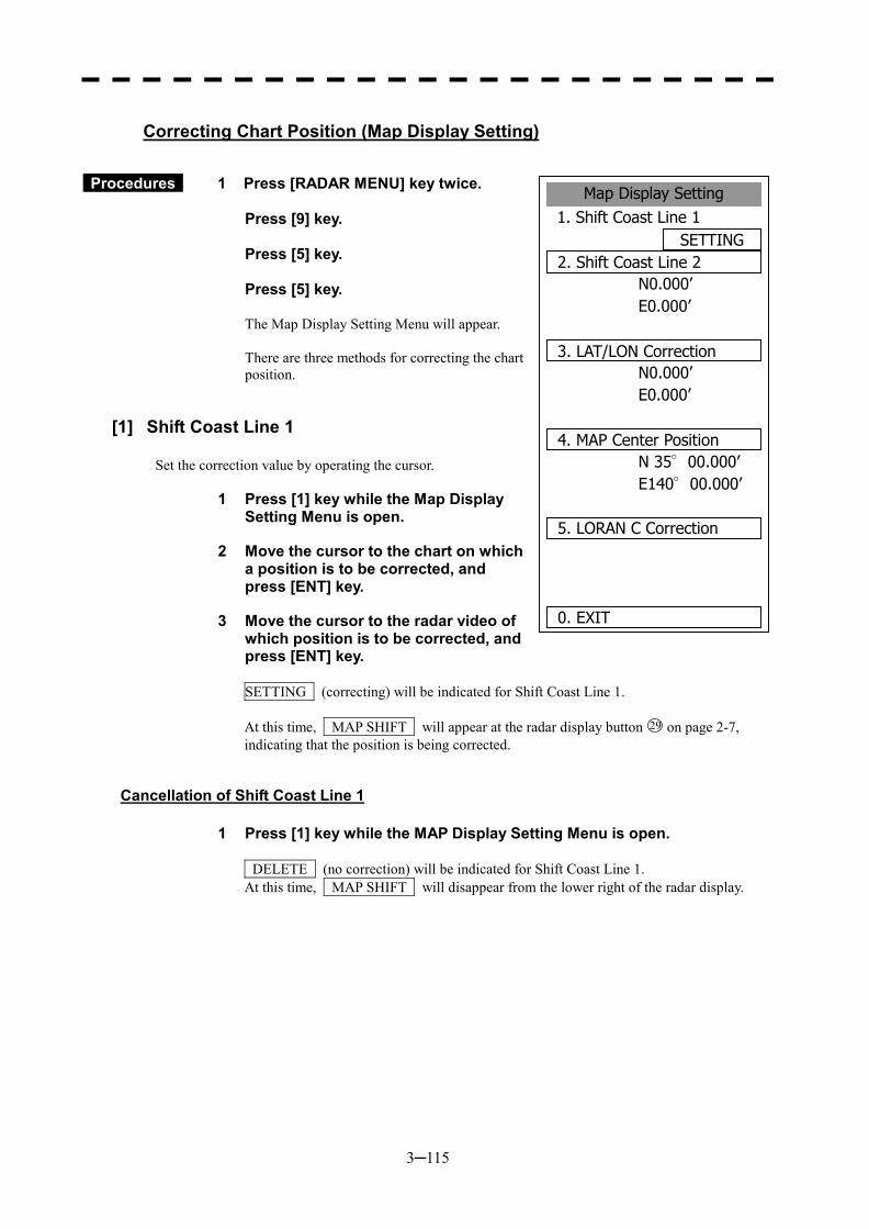
3─115
Map Display Setting1. Shift Coast Line 1
SETTING2. Shift Coast Line 2
N0.000’E0.000’
3. LAT/LON CorrectionN0.000’E0.000’
N 35°00.000’E140°00.000’
5. LORAN C Correction
0. EXIT
4. MAP Center Position
Correcting Chart Position (Map Display Setting)
Procedures 1 Press [RADAR MENU] key twice. Press [9] key. Press [5] key. Press [5] key.
The Map Display Setting Menu will appear.
There are three methods for correcting the chart position.
[1] Shift Coast Line 1
Set the correction value by operating the cursor.
1 Press [1] key while the Map Display Setting Menu is open.
2 Move the cursor to the chart on which a position is to be corrected, and press [ENT] key.
3 Move the cursor to the radar video of which position is to be corrected, and press [ENT] key.
SETTING (correcting) will be indicated for Shift Coast Line 1. At this time, MAP SHIFT will appear at the radar display button 29 on page 2-7, indicating that the position is being corrected.
Cancellation of Shift Coast Line 1
1 Press [1] key while the MAP Display Setting Menu is open.
DELETE (no correction) will be indicated for Shift Coast Line 1. At this time, MAP SHIFT will disappear from the lower right of the radar display.
3─116
3
3.10 APPLIED OPERATIONS �
� �
[2] Shift Coast Line 2
Set a correction value pressing the numeric values. A correction value can be entered in the range -9.999’ to +9.999’.
1 Press [2] key while the Map Display Setting Menu is open.
The chart position correction value input screen will appear.
2 Enter the correction value for the latitudinal direction, pressing the numeric keys.
To switch between the north and south, turn the [MULTI] control.
3 Press [ENT] key.
The correction value for the latitudinal direction will be determined.
4 Enter the correction value for the longitudinal direction, pressing the numeric keys.
To switch between the east and west, turn the [MULTI] control.
5 Press [ENT] key.
The correction value for the longitudinal direction will be determined. At this time, MAP SHIFT will appear at the radar display button 29 on page 2-7, indicating that the position is being corrected.
Cancellation of Shift Coast Line 2
1 Press [2] key while the MAP Display Setting Menu is open.
The chart position correction value input screen will appear.
2 Press [0] key, and then [ENT] key.
The correction value for the latitudinal direction will be set to 0.
3 Press [0] key, and then [ENT] key.
The correction value for the longitudinal direction will be set to 0. At this time, MAP SHIFT will disappear from the lower right of the radar display.
3─117
[3] LAT/LON Correction
This method corrects a chart position by changing the values of latitude and longitude that are sent by the navigation equipment. Only our service engineers are to use this correction method because the contents of data such as trails data to be saved are changed when the method is used. A correction value can be entered in the range -9.999’ to +9.999’.
1 Press [3] while the MAP Display Setting Menu is open.
The latitude/longitude correction value input screen will appear.
2 Enter the correction value for the latitudinal direction, pressing the numeric keys. To switch between the north and south, turn the [MULTI] control.
3 Press [ENT] key.
The correction value for the latitudinal direction will be determined.
4 Enter the correction value for the longitudinal direction, pressing the numeric keys. To switch between the east and west, turn the [MULTI] control.
5 Press [ENT] key.
The correction value for the longitudinal direction will be determined.
Cancellation of LAT/LON Correction
1 Press [3] key while the MAP Display Setting Menu is open.
The latitude/longitude correction value input screen will appear.
2 Press [0] key, and then [ENT] key.
The correction value for the latitudinal direction will be set to 0.
3 Press [0] key, and then [ENT] key.
The correction value for the longitudinal direction will be set to 0.
3─118
3
3.10 APPLIED OPERATIONS �
� �
[4] MAP Center Position
This method corrects a chart position by entering the values of latitude and longitude at own ship’s position in manual mode. If latitude and longitude data sent by the navigation equipment has been entered, the data has priority over the manually entered values.
1 Press [4] key while the MAP Display Setting Menu is open.
The latitude/longitude correction value input screen will appear.
2 Enter the value as latitudinal, pressing the numeric keys.
To switch between the north latitude and south latitude, turn the [MULTI] control.
3 Press [ENT] key.
The entered value will be determined as latitude.
4 Enter the value as longitude, pressing the numeric keys.
To switch between the east longitude and west longitude, turn the [MULTI] control.
5 Press [ENT] key.
The entered value will be determined as longitude.
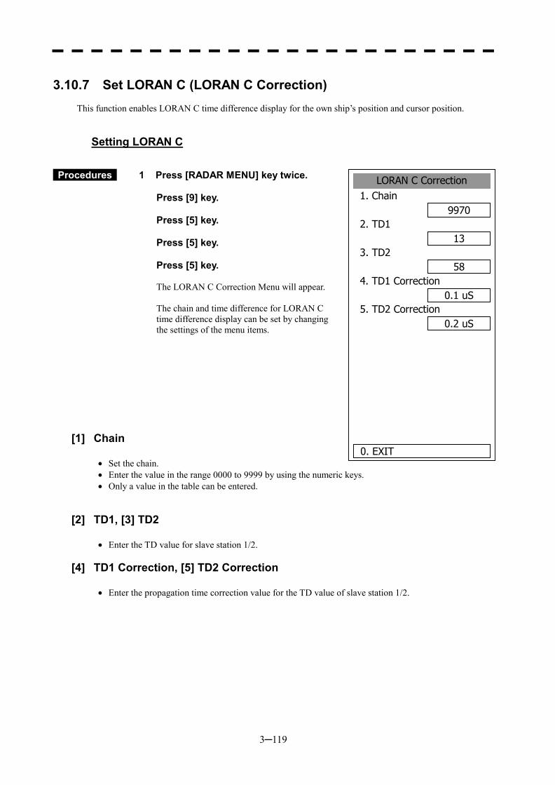
3─119
3.10.7 Set LORAN C (LORAN C Correction)
This function enables LORAN C time difference display for the own ship’s position and cursor position.
Setting LORAN C
Procedures 1 Press [RADAR MENU] key twice. Press [9] key. Press [5] key. Press [5] key. Press [5] key.
The LORAN C Correction Menu will appear.
The chain and time difference for LORAN C time difference display can be set by changing the settings of the menu items.
[1] Chain
�� Set the chain. �� Enter the value in the range 0000 to 9999 by using the numeric keys. �� Only a value in the table can be entered.
[2] TD1, [3] TD2
�� Enter the TD value for slave station 1/2.
[4] TD1 Correction, [5] TD2 Correction
�� Enter the propagation time correction value for the TD value of slave station 1/2.
LORAN C Correction1. Chain
99702. TD1
133. TD2
584. TD1 Correction
0.1 uS5. TD2 Correction
0.2 uS
0. EXIT
3─120
3
3.11 USE FUNCTION SWITCH [FUNC]
“Radar Function Setting” is provided for always obtaining the best radar video by: �� Storing complex radar signal processing settings in the optimum status by use, and �� Calling the setting in accordance with the conditions for using the function.
Functions are factory-set for general use, and the settings can be fine adjusted by operating the menu.
Four function modes are available, and they are factory-set as follows: Function 1: COAST Useful for observing short-range videos Function 2: DEEP SEA Suitable for general ocean navigation Function 3: STORM Useful for observing videos in stormy weather Function 4: LONG Useful for detecting long-range targets
3.11.1 Operation Procedures
Calling a Function
Procedures 1 Press the [FUNC] key.
Each time the [FUNC] key is pressed, the selection changes cyclically as follows: Function Off � Function 1 � Function 2 � Function 3 � Function 4 � Function Off The currently called function mode will be indicated at the lower left of the radar display. * Switching can be done each time button 13 on the radar display on page 2-7 is pressed.
Changing Function Setting (temporary change)
�� When radar signal processing setting is changed by using the menu or button on the radar
display while function 1 to 4 is called, the change is temporarily reflected to the operating state. �� Since this method does not change the memory contents, the new setting is deleted as soon as
another function is called. �� When the previous function is called again, operation is performed according to the memory
contents.
Changing Function Setting (memory contents change)
�� To change the memory contents of functions 1 to 4, use the function setting menu. �� To display the function setting menu, press [RADAR MENU] twice, [1] key, and then [8] key. �� Press the numeric key corresponding to the target function number. �� The function setting menu consists of five pages. To switch between the pages, select [0] key
Previous Page or [9] key Next Page.
3─121
3.11.2 Function Setting Menu Items
The function setting menu has the items below.
Page 1
Page 2
Page 3
Page 4
Page 5
1. Mode Name of the mode to be used 2. IR Radar interference rejection OFF/LOW/MEDIUM/HIGH 3. Process Video process OFF/・・・・ 4. Target Enhance Target expansion OFF/ LEVEL1/LEVEL2/LEVEL3 5. Auto STC/FTC Automatic clutter suppression OFF/Auto SEA/Auto RAIN 7. Save Present State Saving of the present state
1. PL 0.75nm Standard pulse length of 0.75 nm range SP/MP 2. PL 1.5nm Standard pulse length of 1.5 nm range SP/MP/LP 3. PL 3/4nm Standard pulse length of 3 nm range SP/MP/LP 4. PL 6/8nm Standard pulse length of 6 nm range SP/MP/LP 5. PL 12nm Standard pulse length of 12 nm range SP/MP/LP 6. PL 16nm Standard pulse length of 16 nm range SP/MP/LP
1. Video Latitude Dynamic range of radar video NORMAL/WIDE/NARROW 2. Video Noise Rejection Radar video noise rejection OFF/LEVEL1/LEVEL2 3. Auto DR Control Automatic dynamic range control OFF/ON 4. Process Switch Radar video process switching OFF/RANGE FIX/AUTO 5. 2nd Process Mode Second video process mode OFF/・・・・ 6. Process Switch Range Video process switching range Range setting 7. Fast Target Detection Fast moving target detection OFF/ON
1. Trails Interval Radar trails length OFF/・・・・ 2. Trails Mode Radar trails mode TRUE/RELATIVE 3. Trails REF Level Radar trails plotting threshold LEVEL1-4 4. Trails Reduction Thinning of radar trails OFF/LEVEL1-3 5. Time/Cont Combine Superimpose-display of time radar trails and continuous radar trails OFF/ON 6. Trails Process Radar trails video process OFF/ON 7. Max Interval Maximum time for radar trails display FAST/MEDIUM/LONG/SUPER LONG
1. Gain Offset Sensitivity correction Correction value setting 2. XMIT Repitation FREQ. Transmitting repetition frequency NORMAL/ECONOMY/HIPOWER 3. Small Buoy Detection Small target detection mode OFF/ON 4. FishNet Detection Fishnet detection mode OFF/ON 5. Antenna Height Antenna height DEFAULT/-5m/5-10m/10-20m/20m
3─122
3
3.11 USE FUNCTION SWITCH �
� �
3.11.3 Overview of Function Operations
The following outlines the operation of each function selected from the function setting menu:
[Page 1] [1] MODE (Mode)
�� Selects the function name to be indicated at the upper left of the radar display when the function is selected.
�� When the setting is changed back to the factory setting, the initial value of the selected mode is called.
�� The following 11 modes are provided: COAST: Use this mode to monitor a relatively short range, for example, bays and coasts
where many boats and ships are running. (Importance is attached to resolution.) DEEPSEA: Use this mode to monitor a relatively long range, for example, the open sea.
(Importance is attached to long-range sensitivity.) FISHNET: Use this mode to detect small targets such as fishnets of round haul netters hidden
by sea clutter returns. (Importance is attached to sea clutter suppression, and sensitivity to moving targets lowers.)
STORM: Use this mode when many rain/snow clutter returns or sea clutter returns are detected in stormy weather. (Importance is attached to rain/snow clutter and sea clutter suppression, and sensitivity slightly lowers.)
CALM: Use this mode when only a few rain/snow clutter returns or sea clutter returns are detected.
RAIN: Use this mode when sea clutter is not strong but rain/snow clutter is strong. (Importance is attached to rain/snow clutter suppression, and sensitivity slightly lowers.)
BIRD: Use this mode to detect tens of seabirds at low altitude during coastal navigation or hundreds of seabirds at high altitude during ocean navigation.
LONG: Use this mode to detect small targets at relatively long distance in the open sea. BUOY: Use this mode to detect small targets like radio buoys in areas outside the sea
clutter area. (This mode displays targets of which detection probability is low.) USER1: General mode used when the nine modes above are not applicable USER2: General mode used when the nine modes above are not applicable
[Page 1] [2] IR (radar interference rejection)
�� Same function as IR in the MAIN MENU
[Page 1] [3] Process (video process)
�� Same function as PROCESS in the Main Menu
[Page 1] [4] Target Enhance
�� Same function as TARGET ENHANCE in the Main Menu
3─123
[Page 1] [5] Auto SEA/RAIN (Auto STC/FTC)
�� Detects unwanted waves such as rain/snow clutter and sea clutter and automatically suppresses them. �� When the sea state or weather changes, this function automatically performs suppression processing
in accordance with the situation. �� Suppression processing is not full automatic, and requires the operator to control the afterimages of
unwanted waves. �� To control the afterimage of sea clutter, use the [SEA] control. �� To control the afterimage of rain/snow clutter, use the [RAIN] control. �� In areas where the density of unwanted waves is low, unwanted waves may remain being judged as
targets. Thus, use the automatic clutter suppression mode together with the video process mode. �� Characteristics of the automatic clutter suppression function:
OFF: Disables the automatic clutter suppression function. Select OFF when rain/snow clutter and sea clutter are not strong or when the ship
is in a bay. AUTO SEA: Automatically detects the strength of sea clutter, and performs the most suitable
sea clutter suppression processing. Even when the strength of sea clutter varies depending on the wind direction,
AUTO SEA performs the most suitable suppression processing. Land like islands can be displayed naturally. Since rain clouds outside sea clutter areas are recognized as land, there is no effect
of suppressing rain/snow clutter. AUTO RAIN: Along with AUTO SEA, AUTO RAIN automatically detects the strength of
rain/snow clutter, and performs the most suitable rain/snow clutter suppression processing.
When rain clouds are scattered about, AUTO RAIN performs rain/snow clutter suppression processing for only the rain-cloud areas.
Since land is recognized as rain clouds, land videos become obscure.
[Page 2] [1]-[7] PL (Pulse Width)
�� Sets the standard transmitter pulse length in each range. �� When the range is called, the pulse range is used.
[Page 3] [1]-[7] Radar signal processing settings (Process Setting)
�� Same functions as those in the Process Setting Menu generally used
[Page 4] [1]-[7] Radar trails settings (Trails Setting)
�� Same functions as in the Trails Setting of the RADAR Menu generally used
3─124
3
3.11 USE FUNCTION SWITCH �
� �
[Page 5] [1] Gain Offset
�� Corrects sensitivity while the function mode is called. �� Since the displayed noise level varies depending on the combination of the video process mode and
the interference rejection level, sensitivity needs fine adjustment for always obtaining the highest level.
�� The sensitivity correction function saves the correction value set by the sensitivity control in each function mode, so it can obtain the highest sensitivity without the sensitivity control being operated when the function mode is changed.
�� To set high sensitivity, set a value on the “+” side. �� To set low sensitivity, set a value on the “-” side. �� When the radar interference rejection level is increased, the noise level is lowered. Thus, set a
sensitivity correction value to the “+” side. �� When the video process mode 3SCAN CORR, 4SCAN CORR, or 5SCAN CORR is used, the noise
level is lowered. Thus, set a sensitivity correction value to the “+” side. �� When the video process mode REMAIN or PEAK HOLD is used, noise is hard to disappear. Thus,
set a sensitivity correction value to the “-” side.
[Page 5] [2] XMIT Repitation FREQ.
�� Same function as in the TRX Setting of the RADAR Menu generally used
[Page 5] [3] Small Buoy Detection
�� Reduces the loss of signal processing during detection of small targets. OFF: Activates the general signal processing mode. ON: Activates the small buoy detection mode that reduces the loss of signal processing.
[Page 5] [4] FishNet Detection
�� Use this mode to detect small targets hidden by sea clutter returns. �� This function becomes more effective when the AUTO RAIN clutter suppression function is used
together. OFF: Activates the general signal processing mode. ON: Activates the fishnet detection mode.
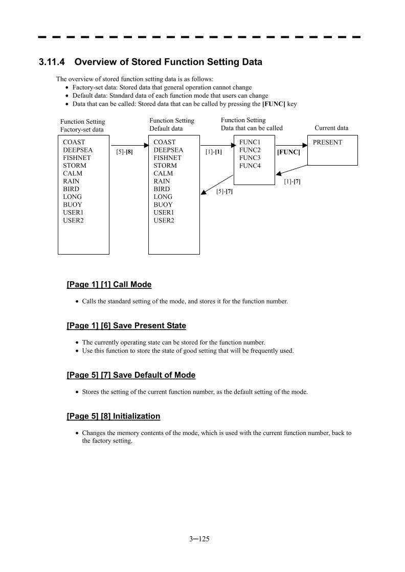
3─125
3.11.4 Overview of Stored Function Setting Data
The overview of stored function setting data is as follows:
�� Factory-set data: Stored data that general operation cannot change �� Default data: Standard data of each function mode that users can change �� Data that can be called: Stored data that can be called by pressing the [FUNC] key
[Page 1] [1] Call Mode
�� Calls the standard setting of the mode, and stores it for the function number.
[Page 1] [6] Save Present State
�� The currently operating state can be stored for the function number. �� Use this function to store the state of good setting that will be frequently used.
[Page 5] [7] Save Default of Mode
�� Stores the setting of the current function number, as the default setting of the mode.
[Page 5] [8] Initialization
�� Changes the memory contents of the mode, which is used with the current function number, back to the factory setting.
COAST DEEPSEA FISHNET STORM CALM RAIN BIRD LONG BUOY USER1 USER2
COAST DEEPSEA FISHNET STORM CALM RAIN BIRD LONG BUOY USER1 USER2
FUNC1 FUNC2 FUNC3 FUNC4
PRESENT [5]-[8] [1]-[1]
[5]-[7]
[FUNC]
[1]-[7]
Function Setting Factory-set data
Function Setting Default data
Function Setting Data that can be called Current data
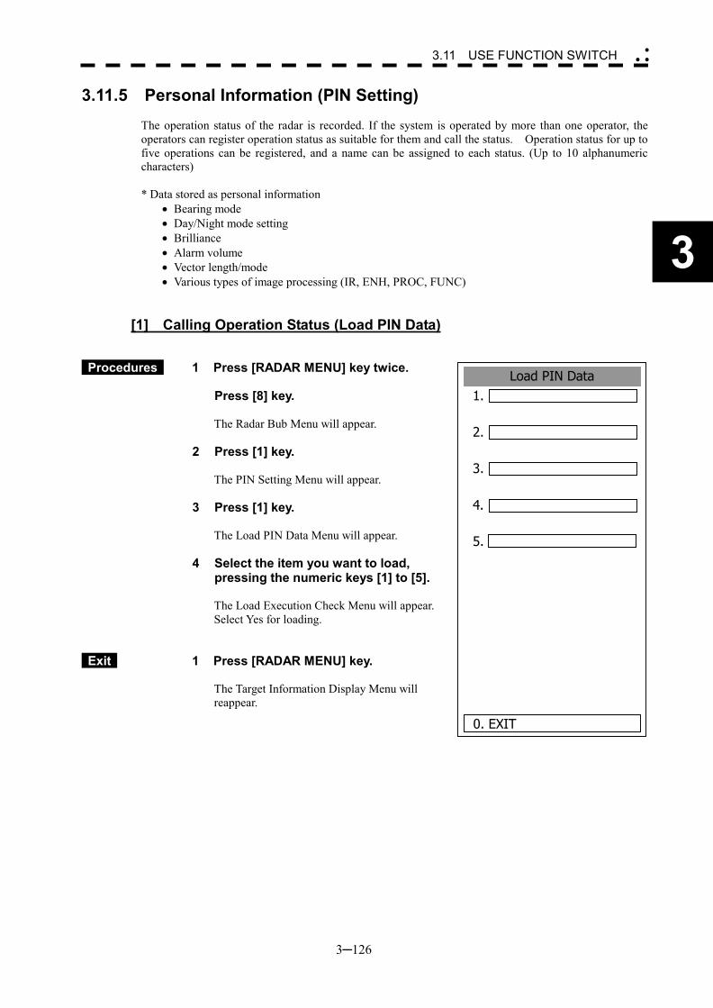
3─126
3
3.11 USE FUNCTION SWITCH �
� �
Load PIN Data1.
2.
3.
4.
5.
0. EXIT
3.11.5 Personal Information (PIN Setting)
The operation status of the radar is recorded. If the system is operated by more than one operator, the operators can register operation status as suitable for them and call the status. Operation status for up to five operations can be registered, and a name can be assigned to each status. (Up to 10 alphanumeric characters) * Data stored as personal information
�� Bearing mode �� Day/Night mode setting �� Brilliance �� Alarm volume �� Vector length/mode �� Various types of image processing (IR, ENH, PROC, FUNC)
[1] Calling Operation Status (Load PIN Data)
Procedures 1 Press [RADAR MENU] key twice.
Press [8] key.
The Radar Bub Menu will appear.
2 Press [1] key.
The PIN Setting Menu will appear.
3 Press [1] key.
The Load PIN Data Menu will appear.
4 Select the item you want to load, pressing the numeric keys [1] to [5].
The Load Execution Check Menu will appear. Select Yes for loading.
Exit 1 Press [RADAR MENU] key.
The Target Information Display Menu will reappear.
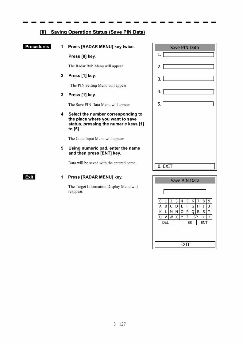
3─127
Save PIN Data1.
2.
3.
4.
5.
0. EXIT
[II] Saving Operation Status (Save PIN Data)
Procedures 1 Press [RADAR MENU] key twice.
Press [8] key.
The Radar Bub Menu will appear.
2 Press [1] key.
The PIN Setting Menu will appear.
3 Press [1] key.
The Save PIN Data Menu will appear.
4 Select the number corresponding to the place where you want to save status, pressing the numeric keys [1] to [5].
The Code Input Menu will appear.
5 Using numeric pad, enter the name and then press [ENT] key.
Data will be saved with the entered name.
Exit 1 Press [RADAR MENU] key.
The Target Information Display Menu will reappear.
1 2 3 4 5 6 7 8 90 B C D E F G H I JA L M N O P Q R S TK V W X Y Z SP < >U
DEL ENT BS
Save PIN Data
EXIT
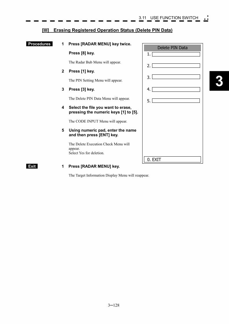
3─128
3
3.11 USE FUNCTION SWITCH �
� �
[III] Erasing Registered Operation Status (Delete PIN Data)
Procedures 1 Press [RADAR MENU] key twice.
Press [8] key.
The Radar Bub Menu will appear.
2 Press [1] key.
The PIN Setting Menu will appear.
3 Press [3] key.
The Delete PIN Data Menu will appear.
4 Select the file you want to erase, pressing the numeric keys [1] to [5].
The CODE INPUT Menu will appear.
5 Using numeric pad, enter the name and then press [ENT] key.
The Delete Execution Check Menu will appear. Select Yes for deletion.
Exit 1 Press [RADAR MENU] key.
The Target Information Display Menu will reappear.
Delete PIN Data1.
2.
3.
4.
5.
0. EXIT
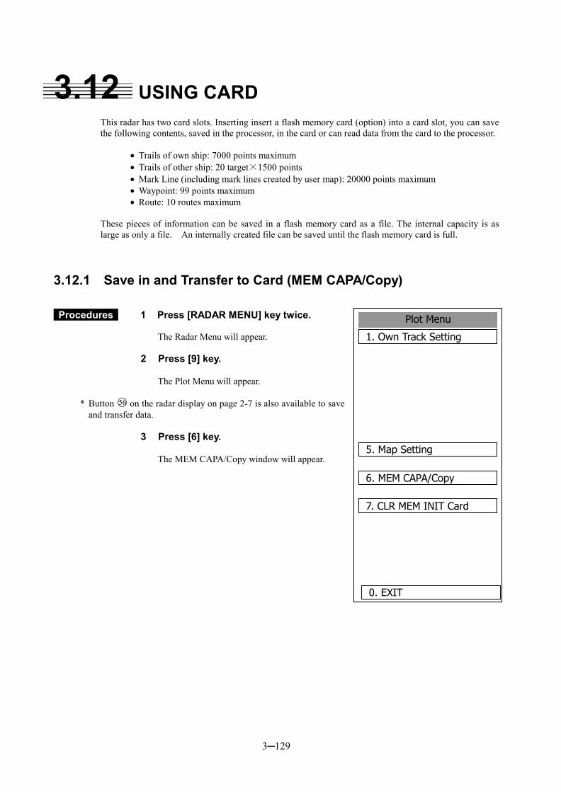
3─129
Plot Menu
1. Own Track Setting
5. Map Setting
6. MEM CAPA/Copy
7. CLR MEM INIT Card
0. EXIT
3.12 USING CARD This radar has two card slots. Inserting insert a flash memory card (option) into a card slot, you can save the following contents, saved in the processor, in the card or can read data from the card to the processor.
�� Trails of own ship: 7000 points maximum �� Trails of other ship: 20 target×1500 points �� Mark Line (including mark lines created by user map): 20000 points maximum �� Waypoint: 99 points maximum �� Route: 10 routes maximum
These pieces of information can be saved in a flash memory card as a file. The internal capacity is as large as only a file. An internally created file can be saved until the flash memory card is full.
3.12.1 Save in and Transfer to Card (MEM CAPA/Copy)
Procedures 1 Press [RADAR MENU] key twice.
The Radar Menu will appear.
2 Press [9] key.
The Plot Menu will appear.
* Button 56 on the radar display on page 2-7 is also available to save and transfer data.
3 Press [6] key.
The MEM CAPA/Copy window will appear.
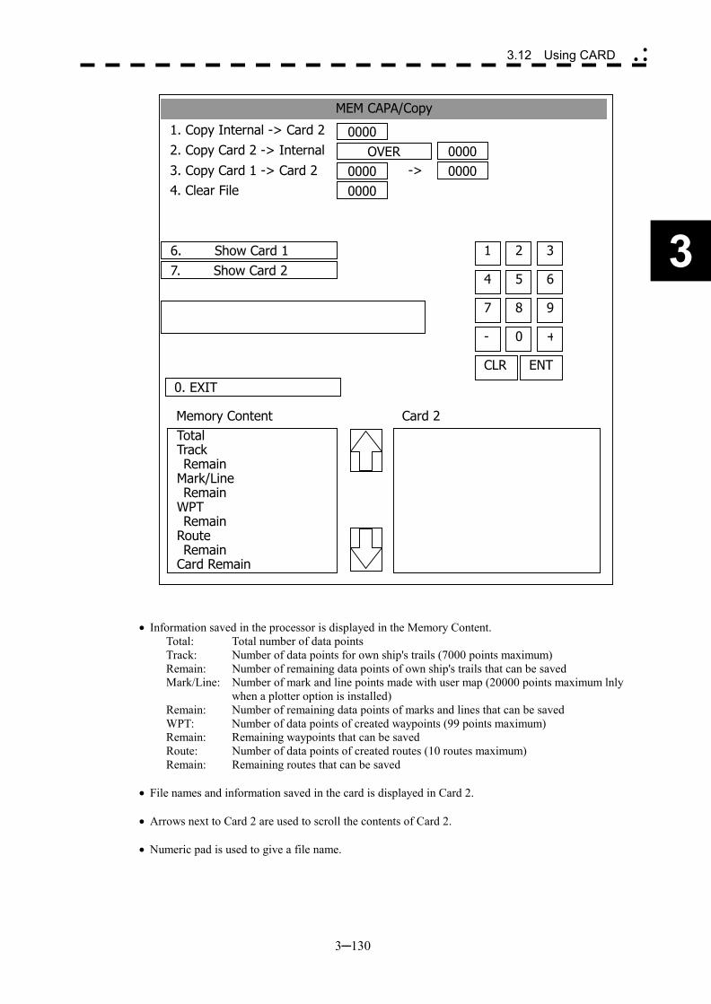
3─130
3
3.12 Using CARD �
� �
�� Information saved in the processor is displayed in the Memory Content. Total: Total number of data points Track: Number of data points for own ship's trails (7000 points maximum) Remain: Number of remaining data points of own ship's trails that can be saved Mark/Line: Number of mark and line points made with user map (20000 points maximum lnly
when a plotter option is installed) Remain: Number of remaining data points of marks and lines that can be saved WPT: Number of data points of created waypoints (99 points maximum) Remain: Remaining waypoints that can be saved Route: Number of data points of created routes (10 routes maximum) Remain: Remaining routes that can be saved
�� File names and information saved in the card is displayed in Card 2.
�� Arrows next to Card 2 are used to scroll the contents of Card 2.
�� Numeric pad is used to give a file name.
MEM CAPA/Copy
1. Copy Internal -> Card 22. Copy Card 2 -> Internal3. Copy Card 1 -> Card 24. Clear File
0. EXIT
6. Show Card 17. Show Card 2
0000OVER
00000000
0000 0000 ->
4 5 6
1 2 3
7 8 9
- 0 +
CLR ENT
Memory ContentTotal Track Remain Mark/Line Remain WPT Remain Route Remain Card Remain
Card 2
3─131
[I] Copy Internal Information to Card 2 (Copy Internal � Card 2)
Procedures 1 When the CAPA/Copy Menu appears, press [1] key.
A file name to copy Internal information to Card 2 can be entered.
2 Using the numeric pad, enter a file name.
After having enter the name, select ENT.CLR will be cancelled. The system writes internal information into Card 2 with an entered number used as a file name. The capacity of information that can be saved in the internal portion is limited to the maximum number of points in items described on the previous page. For the capacity of information that can be saved in a card, the system can save Information in a card until the card capacity is filled with a file, counting the information saved in the internal portion as a file.
[II] Read Information from Card 2 to Internal Portion(Copy Card 2 � Internal)
Procedures 1 When the CAPA/Copy Menu appears, press [2] key.
A file name to copy information from Internal portion to Card 2 can be entered. Read the file name displayed in the Card 2 window.
2 Using the numeric pad, enter a file name.
After having enter the name, select ENT.CLR will be cancelled. The entered file name is read from Card 2 to the internal portion.
When information is to be transferred from Card 2 to the internal portion in the ADD mode, the information can be copied from multiple files. However, information cannot be read when the number of points for an item has reached the maximum. In the ADD mode, the WPT and Route are overwritten.
[III] Copy Information from Card 1 to Card 2 (Copy Card 1 � Card 2)
Procedures 1 When the CAPA/Copy Menu appears, press [3] key.
A file name to copy information from Card 1 to Card 2 can be entered.
2 Using the numeric pad, enter a file name. Using the numeric pad, euter a file name to be copieed. After having enter the name, select ENT. CLR will be cancelled.
3 Using the numeric pad, enter a file name to copy.
After having enter the name, select ENT.CLR will be cancelled. The entered file number is copied from Card 1 to Card 2.
3─132
3
3.12 Using CARD �
� �
[IV] Delete File from Card 2 (Clear File)
Procedures 1 When the CAPA/Copy Menu appears, press [4] key.
A file name to clear file can be entered.
2 Using the numeric pad, enter a file name.
After having enter the name, select ENT.CLR will be cancelled. The entered file number is deleted from Card 2.
[VI, VII] View Information in Card (Show Card)
Procedures 1 When the MEM CAPA/Copy Menu appears, presssing numeric key [6] or
[7].
6: Card slot 1 7: Card slot 2 Select a card to be displayed.
Exit 1 Press [0] key.
The MEM CAPA/Copy window will be closed.
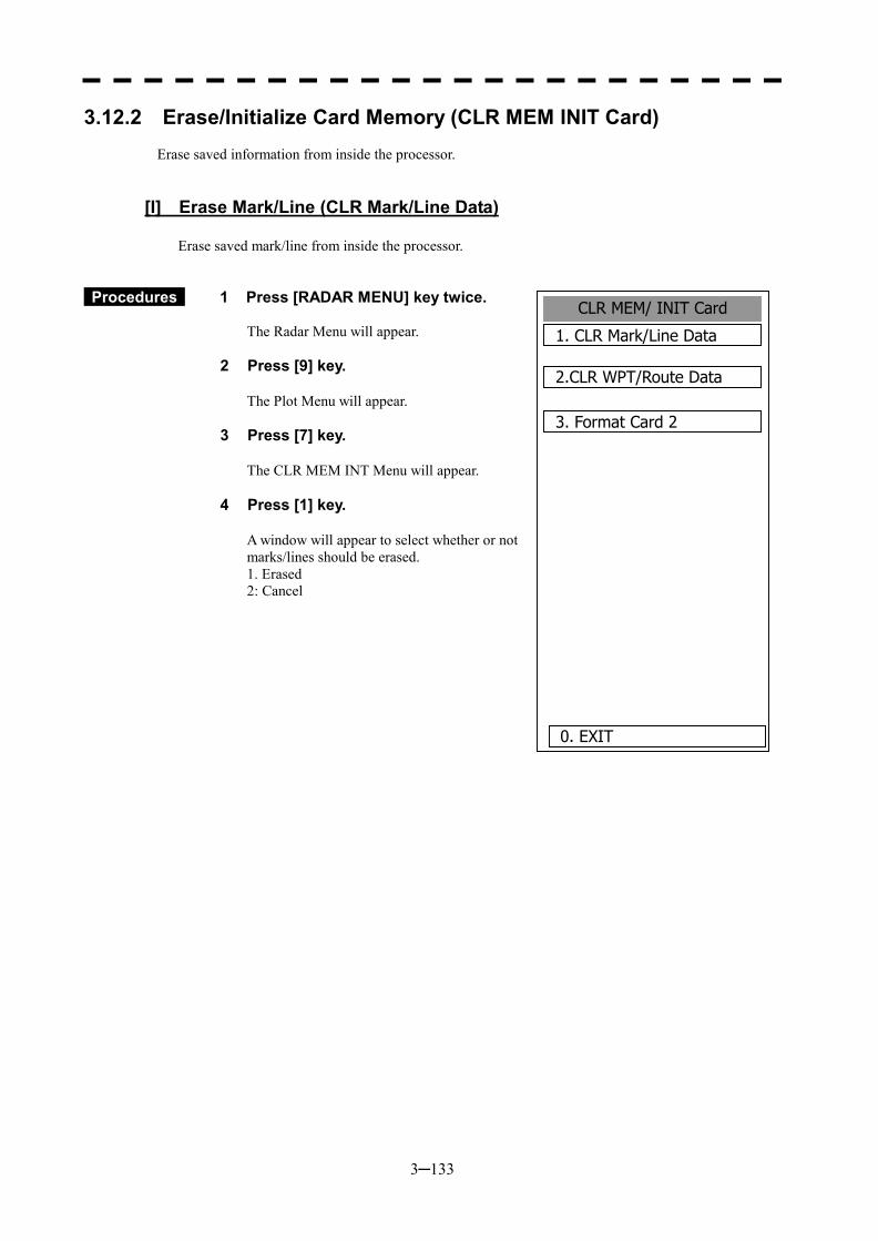
3─133
3.12.2 Erase/Initialize Card Memory (CLR MEM INIT Card) Erase saved information from inside the processor.
[I] Erase Mark/Line (CLR Mark/Line Data)
Erase saved mark/line from inside the processor.
Procedures 1 Press [RADAR MENU] key twice.
The Radar Menu will appear.
2 Press [9] key.
The Plot Menu will appear.
3 Press [7] key.
The CLR MEM INT Menu will appear.
4 Press [1] key.
A window will appear to select whether or not marks/lines should be erased. 1. Erased 2: Cancel
CLR MEM/ INIT Card
1. CLR Mark/Line Data
2.CLR WPT/Route Data
3. Format Card 2
0. EXIT
3─134
3
3.12 Using CARD �
� �
[II] Erase Waypoint/Route (CLR WPT/Route Data)
Erase saved WPT/Route from inside the processor.
Procedures 1 Press [RADAR MENU] key twice.
The Radar Menu will appear.
2 Press [9] key.
The Plot Menu will appear.
3 Press [7] key.
The CLR MEM INIT Card Menu will appear.
4 Press [2] key.
The Waypoint/Route Erase Execution window will appear. 1. Erase 2: Cancel
[III] Initialize Card 2 (Format Card 2)
Initialize Card 2.
Procedures 1 Press [RADAR MENU] key twice.
The Radar Menu will appear.
2 Press [9] key.
The Plot Menu will appear.
3 Press [7] key.
The CLR MEM INIT Card Menu will appear.
4 Press [3] key.
The window to select whether or not Card 2 is initialized will appear. 1. Initialize 2: Cancel

SECTION 4 MEASUREMENT OF
RANGE AND BEARING
4.1 Measurement by Trackball ............................. 4-1 4.2 Measurement by Range Rings ....................... 4-2 4.3 Measurement by EBLs and VRMs ................. 4-3 4.4 Measurement between Two Optional Points. 4-5

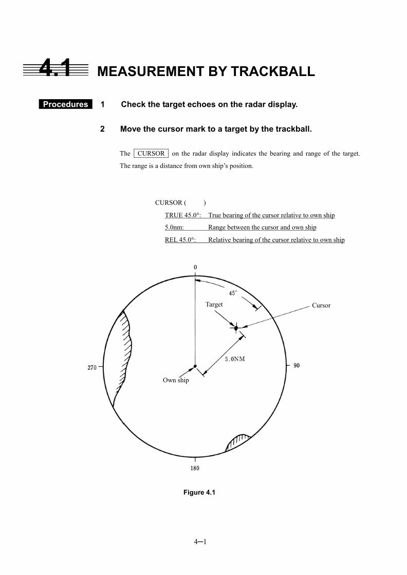
4─1
4.1 MEASUREMENT BY TRACKBALL
Procedures 1 Check the target echoes on the radar display.
2 Move the cursor mark to a target by the trackball.
The CURSOR on the radar display indicates the bearing and range of the target.
The range is a distance from own ship’s position.
CURSOR ( )
TRUE 45.0�: True bearing of the cursor relative to own ship
5.0nm: Range between the cursor and own ship
REL 45.0�: Relative bearing of the cursor relative to own ship
Figure 4.1
Target Cursor
Own ship
4─2
4
4.2 MEASUREMENT BY RANGE RINGS
Procedures 1 Press [RR/HL] key.
The Range Rings will appear on the radar display. The range between the target and own ships can be determined by visually measuring the target’s position that lies between two range rings. (The range ring interval is fixed and indicated within the radar display � on page 2-9.)
4─3
4.3 MEASUREMENT BY EBLS AND VRMS ・・ Procedures 1 Press [EBL1] key to select EBL1 display and operation.
The EBL1 indication at the lower right of the radar display will be selected and the EBL1 will appear as a broken-line on the PPI display.
2 Turn the [EBL] control to put EBL1 on a target. The bearing of the EBL1 will appear at the lower right of the radar display. The EBL1 bearing represents the target’s bearing.
3 Press [VRM1] key to select VRM1 display and operation. The VRM1 indication at the lower right of the radar display will be selected and the VRM1 will appear as a broken-line circle on the PPI display.
4 Move the broken-line VRM1 to the target by using the [VRM]
control. The range of the VRM1 from own ship will appear at the lower right of the radar display. The range of VRM1 signifies a distance between the target and own ship. Refer to Figure 4.2 in the next page. In this Figure 4.2, the range and bearing are; Range: 5.0nm Bearing: 45.0�
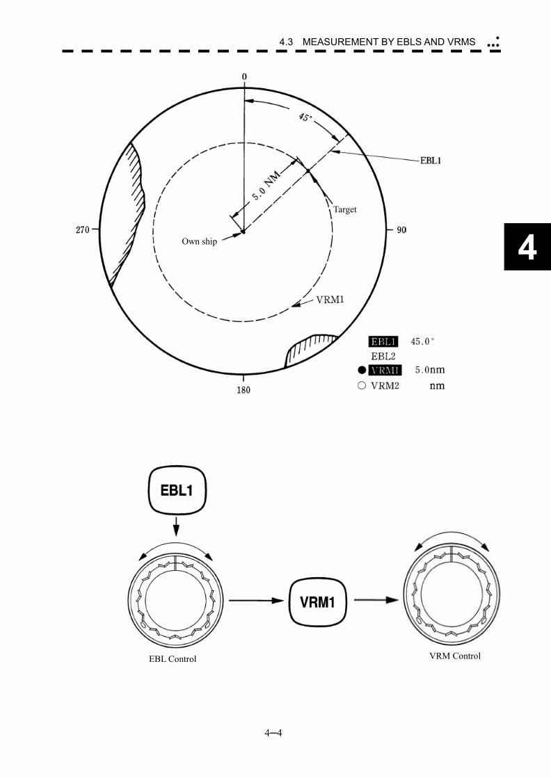
4─4
4
4.3 MEASUREMENT BY EBLS AND VRMS �
���
Figure 4.2
VRM ControlEBL Control
Target
Own ship
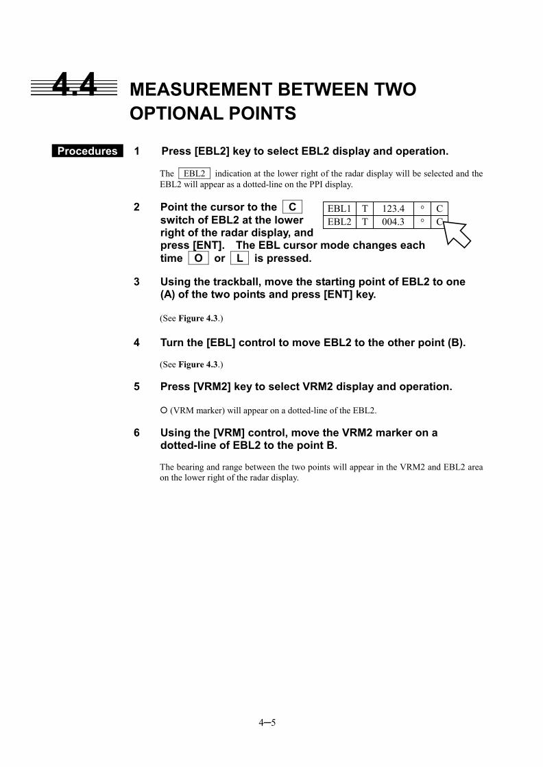
4─5
123.4EBL1 T � C004.3EBL2 T � C
4.4 MEASUREMENT BETWEEN TWO OPTIONAL POINTS
Procedures 1 Press [EBL2] key to select EBL2 display and operation. The EBL2 indication at the lower right of the radar display will be selected and the EBL2 will appear as a dotted-line on the PPI display.
2 Point the cursor to the C switch of EBL2 at the lower right of the radar display, and press [ENT]. The EBL cursor mode changes each time O or L is pressed.
3 Using the trackball, move the starting point of EBL2 to one (A) of the two points and press [ENT] key.
(See Figure 4.3.)
4 Turn the [EBL] control to move EBL2 to the other point (B).
(See Figure 4.3.)
5 Press [VRM2] key to select VRM2 display and operation.
� (VRM marker) will appear on a dotted-line of the EBL2.
6 Using the [VRM] control, move the VRM2 marker on a dotted-line of EBL2 to the point B. The bearing and range between the two points will appear in the VRM2 and EBL2 area on the lower right of the radar display.
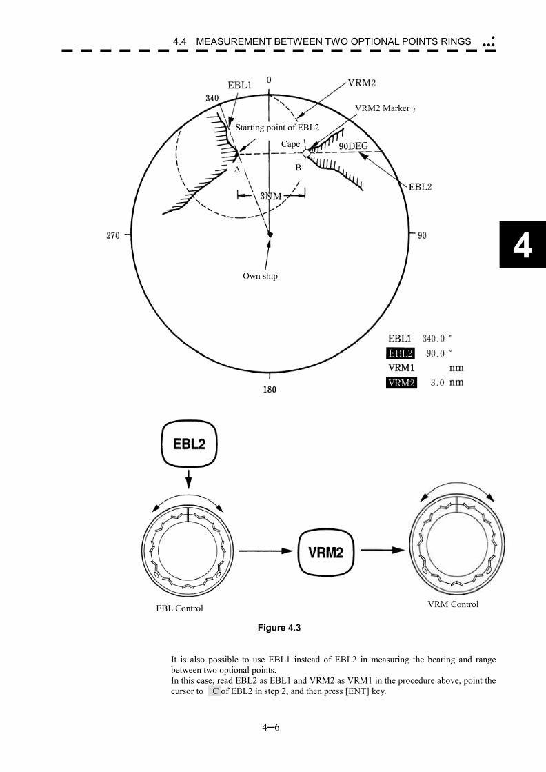
4─6
4
4.4 MEASUREMENT BETWEEN TWO OPTIONAL POINTS RINGS �
���
Figure 4.3
It is also possible to use EBL1 instead of EBL2 in measuring the bearing and range between two optional points. In this case, read EBL2 as EBL1 and VRM2 as VRM1 in the procedure above, point the cursor to C of EBL2 in step 2, and then press [ENT] key.
EBL Control
Starting point of EBL2
Cape
B
VRM2 Marker
Own ship
A
VRM Control

SECTION 5 OPERATION OF ARPA AND AIS
5.1 PREPARATION........................................................... 5-2
5.1.1 Collision Avoidance ............................................ 5-4 5.1.2 Definitions of Symbols ....................................... 5-7 5.1.3 Setting Collision Decision Criteria
(CPA/TCPA Limit)................................................. 5-9 5.1.4 Setting Vectors (Vector Time)........................... 5-10 5.1.5 Setting CPA Ring (CPA Ring).............................5-11 5.1.6 Setting Automatic Acquisition Key Assignment
(GZ Alarm Key Setting) ................................... 5-12 5.2 EPA OPERATION ..................................................... 5-13
5.2.1 Plotting Targets ................................................. 5-13 5.2.2 Modifying Plotted Target Data .......................... 5-14 5.2.3 Canceling Plotted Target Data.......................... 5-14 5.2.4 Displaying Numeric Data of Plotted Targets.... 5-15 5.2.5 Setting EPA Alarm (Audible Warning).............. 5-16
5.3 ATA/ARPA OPERATION........................................... 5-17 5.3.1 Acquiring Target................................................ 5-17 5.3.2 Canceling Unwanted Targets............................ 5-19 5.3.3 Displaying Target ID No.
(Target Number Display) ................................... 5-20 5.3.4 ATA/ARPA Data Display .................................... 5-21 5.3.5 Target Data Display........................................... 5-26
5.3.6 Alarm Display .................................................... 5-30 5.3.7 Trial Maneuvering (Trial) ................................... 5-34 5.3.8 ATA/ARPA Simulation........................................ 5-38 5.3.9 Setting ATA/ARPA Tracks (ATA Track Setting). 5-44
5.4 AIS OPERATION....................................................... 5-51 5.4.1 Initial Setting...................................................... 5-52 5.4.2 Setting AIS Display Function (AIS Function) ... 5-54 5.4.3 Activating AIS Targets....................................... 5-55 5.4.4 Deactivating AIS Targets................................... 5-56 5.4.5 Setting AIS Symbol Display Function
(AIS Symbol Display)......................................... 5-57 5.4.6 Displaying Numeric Data of AIS Targets .......... 5-58 5.4.7 Setting ATA/ARPA Symbol Display Function
(ATA Symbol Display) ........................................ 5-60 5.4.8 Setting AIS Filter (AIS Filter Setting) ................ 5-61 5.4.9 Deciding AIS Target and ARPA Target as the
Same One (Identical Distance).......................... 5-64 5.4.10 Conditions for Deciding AIS Target to be Lost
............................................................................ 5-66 5.4.11 Displaying AIS Symbols.................................. 5-67 5.4.12 AIS Alarm Display............................................ 5-68 5.4.13 Restrictions...................................................... 5-69
5─1
USAGE OF ARPA
��There are the following limitations on use of the target acquisition and
tracking functions of ARPA: Use these radar only as assisting device for navigation. The final decision for navigation should made by the officer himself. [I] Resolution between adjacent targets and swapping during
automatic tracking Depending on the particular distance and echo size, resolution between
adjacent targets during automatic tracking usually ranges somewhere between 0.03 to 0.05 nm. If multiple targets approach each other, resolution will become about 0.03 nm and this may cause the system to regard them as one target and thus to swap them or lose part of them. Such swapping or less of targets may also occur if the picture of the target being tracked is affected by rain/snow clutter returns or sea clutter returns or moves very close to land.
[II] Intensity of echoes and the tracking function The intensity of echoes and the tracking function have a correlationship,
and thus the target will be lost if no echoes are detected during six scans in succession. If a lost target exists, therefore, radar gain must be increased to support detection of the target. If, however, radar gain is increased too significantly, sea clutter returns or other noise may be erroneously detected and tracked as a target, and resultingly, a false alarm may be issued.
[III] Adverse effects of error sources on automatic tracking To execute accurate tracking, it becomes necessary first to appropriately
adjust the [GAIN], [SEA] and [RAIN] controls of the radar so that the target to be acquired and tracked id clearly displayed on the radar display. Inappropriate settings of these controls reduce the reliability/accuracy of automatic tracking.
Attention
5─2
5
5.1 PREPARATION This section explains the features of EPA/ATA/ARPA and AIS functions, and the initial setting for using each function. The four plotting functions below are available with this radar equipment. An optional device is necessary for using each of the ATA, ARPA, and AIS functions.
EPA (Electronic Plotting Aid) function
The EPA function calculates the course and speed of a target from the positions of the target that have been entered manually at specified intervals. The EPA function is available when the ATA and ARPA options are not installed.
ATA (Automatic Tracking Aid) function
The ATA function calculates the course and speed of a target by automatically tracking the target’s move. The ATA function enables automatic acquisition of targets by using the guard zone function. The ATA function is available when the ATA option is installed. (This function cannot be used with the ARPA option.)
ARPA (Automatic Radar Plotting Aid) function
The ARPA function calculates the course and speed of a target by automatically tracking the target’s move. The ARPA function enables automatic acquisition of targets by using the guard zone function. The ARPA function also enables the simulation of the maneuvering method for avoiding collision by using the trial maneuvering function. The ARPA function is available when the ARPA option is installed. The ARPA function provides higher-level functions than the ATA function. (This function cannot be used with the ATA option.)
AIS (Automatic Identification System) function
The AIS function shows the target’s information on the radar display, using other ships’ information sent out from the AIS unit. The AIS function is available when the optional AIS interface is installed.
5─3
��The menu display is changed to “ATA” or “ARPA” according to option provided in this radar equipment. Where the ARPA option is provided, the ARPA Setting is displayed in the menu.Also where the ATA option is provided, the ATA Setting is displayed in the menu. This manual basically displays using “ATA”.
Attention
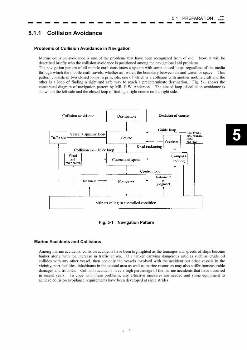
5─4
5
5.1 PREPARATION ��
���
5.1.1 Collision Avoidance
Problems of Collision Avoidance in Navigation Marine collision avoidance is one of the problems that have been recognized from of old. Now, it will be described briefly who the collision avoidance is positioned among the navigational aid problems. The navigation pattern of all mobile craft constitutes a system with some closed loops regardless of the media through which the mobile craft travels, whether air, water, the boundary between air and water, or space. This pattern consists of two closed loops in principle, one of which is a collision with another mobile craft and the other is a loop of finding a right and safe way to reach a predeterminate destination. Fig. 5-1 shows the conceptual diagram of navigation pattern by MR. E.W. Anderson. The closed loop of collision avoidance is shown on the left side and the closed loop of finding a right course on the right side.
Fig. 5-1 Navigation Pattern
Marine Accidents and Collisions Among marine accidents, collision accidents have been highlighted as the tonnages and speeds of ships become higher along with the increase in traffic at sea. If a tanker carrying dangerous articles such as crude oil collides with any other vessel, then not only the vessels involved with the accident but other vessels in the vicinity, port facilities, inhabitants in the coastal area as well as marine resources may also suffer immeasurable damages and troubles. Collision accidents have a high percentage of the marine accidents that have occurred in recent years. To cope with these problems, any effective measures are needed and some equipment to achieve collision avoidance requirements have been developed at rapid strides.
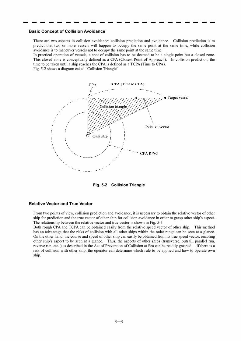
5─5
Basic Concept of Collision Avoidance There are two aspects in collision avoidance: collision prediction and avoidance. Collision prediction is to predict that two or more vessels will happen to occupy the same point at the same time, while collision avoidance is to maneuver vessels not to occupy the same point at the same time. In practical operation of vessels, a spot of collision has to be deemed to be a single point but a closed zone. This closed zone is conceptually defined as a CPA (Closest Point of Approach). In collision prediction, the time to be taken until a ship reaches the CPA is defined as a TCPA (Time to CPA). Fig. 5-2 shows a diagram caked “Collision Triangle”.
Fig. 5-2 Collision Triangle
Relative Vector and True Vector From two points of view, collision prediction and avoidance, it is necessary to obtain the relative vector of other ship for prediction and the true vector of other ship for collision avoidance in order to grasp other ship’s aspect. The relationship between the relative vector and true vector is shown in Fig. 5-3 Both rough CPA and TCPA can be obtained easily from the relative speed vector of other ship. This method has an advantage that the risks of collision with all other ships within the radar range can be seen at a glance. On the other hand, the course and speed of other ship can easily be obtained from its true speed vector, enabling other ship’s aspect to be seen at a glance. Thus, the aspects of other ships (transverse, outsail, parallel run, reverse run, etc. ) as described in the Act of Prevention of Collision at Sea can be readily grasped. If there is a risk of collision with other ship, the operator can determine which rule to be applied and how to operate own ship.
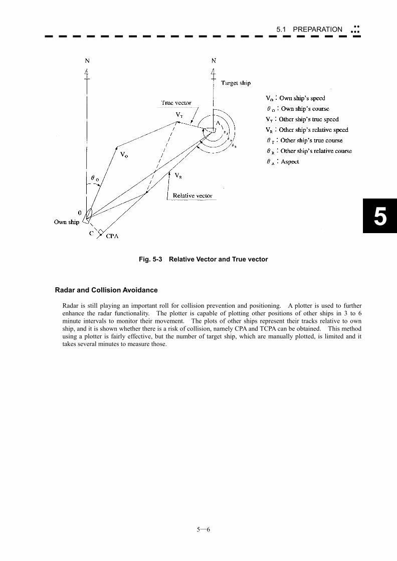
5─6
5
5.1 PREPARATION ��
���
Fig. 5-3 Relative Vector and True vector
Radar and Collision Avoidance Radar is still playing an important roll for collision prevention and positioning. A plotter is used to further enhance the radar functionality. The plotter is capable of plotting other positions of other ships in 3 to 6 minute intervals to monitor their movement. The plots of other ships represent their tracks relative to own ship, and it is shown whether there is a risk of collision, namely CPA and TCPA can be obtained. This method using a plotter is fairly effective, but the number of target ship, which are manually plotted, is limited and it takes several minutes to measure those.
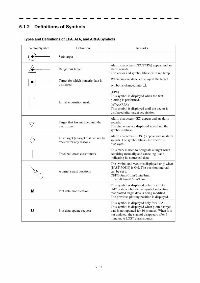
5─7
5.1.2 Definitions of Symbols
Types and Definitions of EPA, ATA, and ARPA Symbols Vector/Symbol Definition Remarks
Safe target
Dangerous target
Alarm characters (CPA/TCPA) appear and an alarm sounds. The vector and symbol blinks with red lamp.
Target for which numeric data is displayed
When numeric data is displayed, the target
symbol is changed into □.
Initial acquisition mark
(EPA) This symbol is displayed when the first plotting is performed. (ATA/ARPA) This symbol is displayed until the vector is displayed after target acquisition.
Target that has intruded into the guard zone
Alarm characters (GZ) appear and an alarm sounds. The characters are displayed in red and the symbol is blinks.
Lost target (a target that can not be tracked for any reason)
Alarm characters (LOST) appear and an alarm sounds. The symbol blinks. No vector is displayed.
Trackball cross cursor mark
This mark is used to designate a target when acquiring manually and canceling it and indicating its numerical data.
A target’s past positions
The symbol and vector is displayed only when [PAST POSN] is ON. The position interval can be set to OFF/0.5min/1min/2min/4min 0.1nm/0.2nm/0.5nm/1nm
M Plot data modification
This symbol is displayed only for (EPA). “M” is shown beside the symbol indicating that plotted target data is being modified. The previous plotting position is displayed.
U Plot data update request
This symbol is displayed only for (EPA). This symbol is displayed when plotted target data is not updated for 10 minutes. When it is not updated, the symbol disappears after 5 minutes. A LOST alarm sounds.
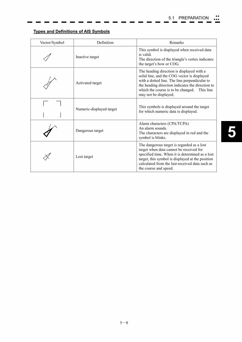
5─8
5
5.1 PREPARATION ��
���
Types and Definitions of AIS Symbols
Vector/Symbol Definition Remarks
Inactive target
This symbol is displayed when received data is valid. The direction of the triangle’s vertex indicates the target’s bow or COG.
Activated target
The heading direction is displayed with a solid line, and the COG vector is displayed with a dotted line. The line perpendicular to the heading direction indicates the direction to which the course is to be changed. This line may not be displayed.
Numeric-displayed target This symbols is displayed around the target for which numeric data is displayed.
Dangerous target
Alarm characters (CPA/TCPA) An alarm sounds. The characters are displayed in red and the symbol is blinks.
Lost target
The dangerous target is regarded as a lost target when data cannot be received for specified time. When it is determined as a lost target, this symbol is displayed at the position calculated from the last-received data such as the course and speed.
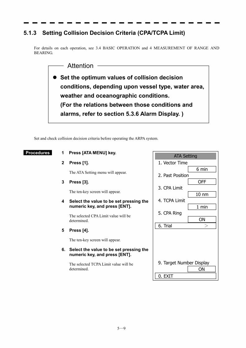
5─9
ATA Setting1. Vector Time
6 min2. Past Position
OFF3. CPA Limit
10 nm4. TCPA Limit
1 min5. CPA Ring
ON6. Trial >
9. Target Number Display
0. EXIT ON
5.1.3 Setting Collision Decision Criteria (CPA/TCPA Limit) For details on each operation, see 3.4 BASIC OPERATION and 4 MEASUREMENT OF RANGE AND BEARING. Set and check collision decision criteria before operating the ARPA system.
Procedures 1 Press [ATA MENU] key.
2 Press [1].
The ATA Setting menu will appear.
3 Press [3]. The ten-key screen will appear.
4 Select the value to be set pressing the numeric key, and press [ENT]. The selected CPA Limit value will be determined.
5 Press [4]. The ten-key screen will appear.
6. Select the value to be set pressing the numeric key, and press [ENT]. The selected TCPA Limit value will be determined.
��Set the optimum values of collision decision conditions, depending upon vessel type, water area, weather and oceanographic conditions. (For the relations between those conditions and alarms, refer to section 5.3.6 Alarm Display. )
Attention
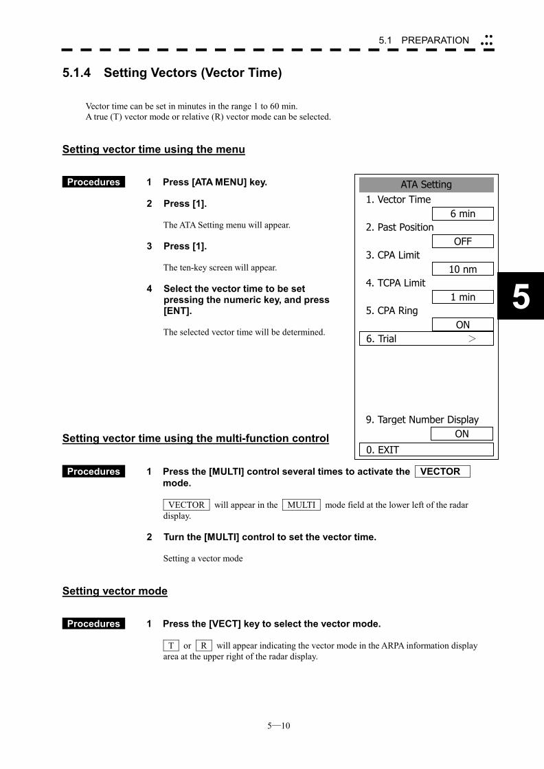
5─10
5
5.1 PREPARATION ��
���
ATA Setting1. Vector Time
6 min2. Past Position
OFF3. CPA Limit
10 nm4. TCPA Limit
1 min5. CPA Ring
ON6. Trial >
9. Target Number Display
0. EXIT
ON
5.1.4 Setting Vectors (Vector Time) Vector time can be set in minutes in the range 1 to 60 min. A true (T) vector mode or relative (R) vector mode can be selected.
Setting vector time using the menu
Procedures 1 Press [ATA MENU] key.
2 Press [1].
The ATA Setting menu will appear.
3 Press [1].
The ten-key screen will appear.
4 Select the vector time to be set
pressing the numeric key, and press [ENT].
The selected vector time will be determined.
Setting vector time using the multi-function control
Procedures 1 Press the [MULTI] control several times to activate the VECTOR
mode.
VECTOR will appear in the MULTI mode field at the lower left of the radar display.
2 Turn the [MULTI] control to set the vector time.
Setting a vector mode
Setting vector mode
Procedures 1 Press the [VECT] key to select the vector mode. T or R will appear indicating the vector mode in the ARPA information display area at the upper right of the radar display.
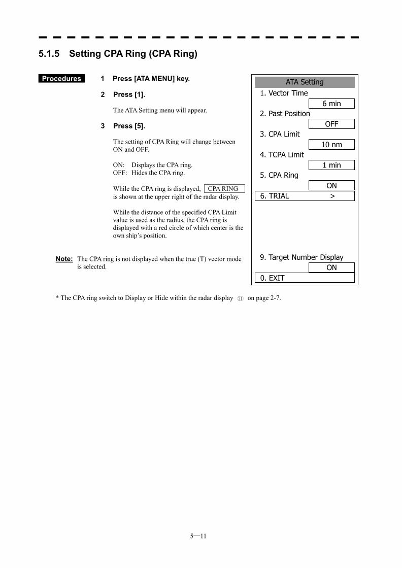
5─11
ATA Setting1. Vector Time
6 min2. Past Position
OFF3. CPA Limit
10 nm4. TCPA Limit
1 min5. CPA Ring
ON6. TRIAL >
9. Target Number Display
0. EXIT ON
5.1.5 Setting CPA Ring (CPA Ring)
Procedures 1 Press [ATA MENU] key.
2 Press [1].
The ATA Setting menu will appear.
3 Press [5].
The setting of CPA Ring will change between ON and OFF. ON: Displays the CPA ring. OFF: Hides the CPA ring. While the CPA ring is displayed, CPA RING is shown at the upper right of the radar display. While the distance of the specified CPA Limit value is used as the radius, the CPA ring is displayed with a red circle of which center is the own ship’s position.
Note: The CPA ring is not displayed when the true (T) vector mode is selected.
* The CPA ring switch to Display or Hide within the radar display 21 on page 2-7.
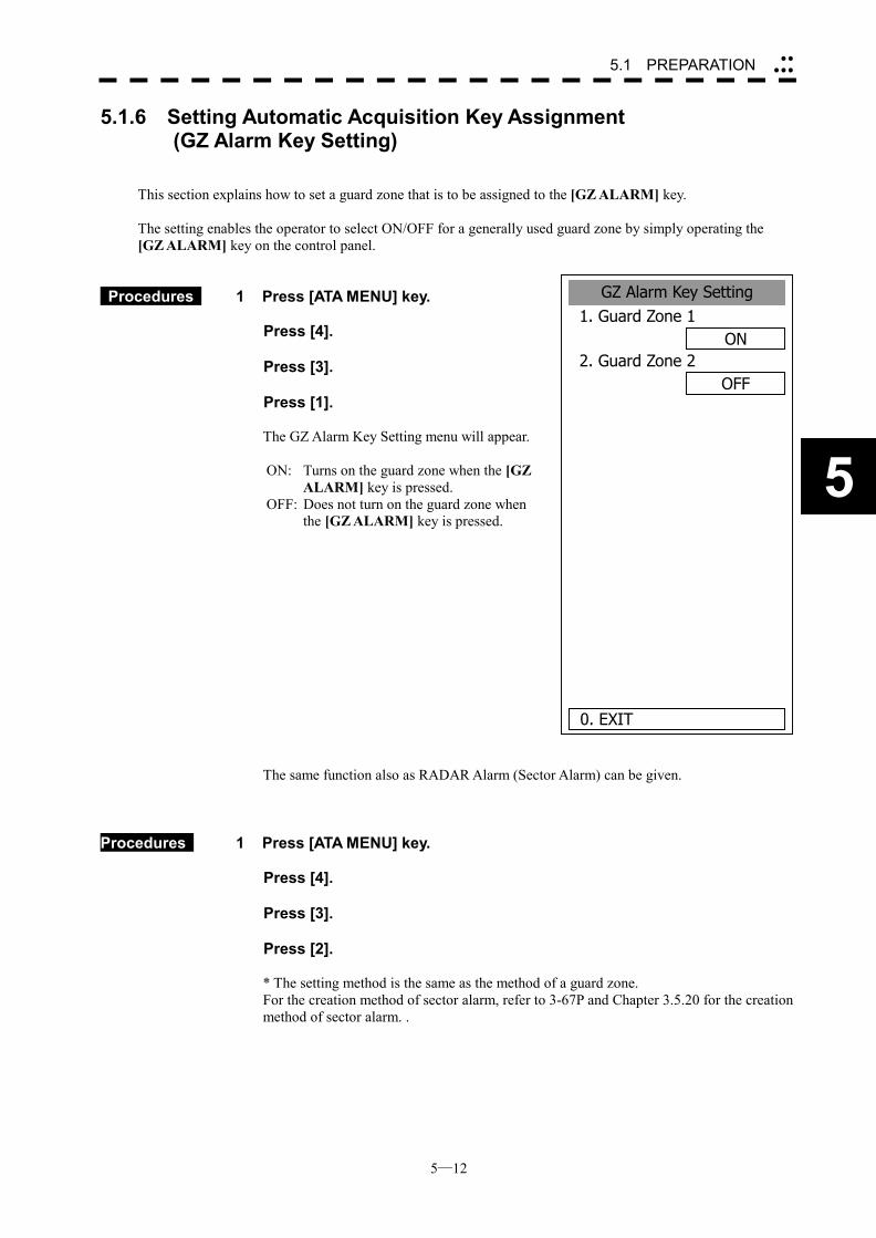
5─12
5
5.1 PREPARATION ��
���
GZ Alarm Key Setting1. Guard Zone 1
ON2. Guard Zone 2
OFF
0. EXIT
5.1.6 Setting Automatic Acquisition Key Assignment (GZ Alarm Key Setting)
This section explains how to set a guard zone that is to be assigned to the [GZ ALARM] key. The setting enables the operator to select ON/OFF for a generally used guard zone by simply operating the [GZ ALARM] key on the control panel.
Procedures 1 Press [ATA MENU] key.
Press [4]. Press [3]. Press [1].
The GZ Alarm Key Setting menu will appear.
ON: Turns on the guard zone when the [GZ
ALARM] key is pressed. OFF: Does not turn on the guard zone when
the [GZ ALARM] key is pressed. The same function also as RADAR Alarm (Sector Alarm) can be given.
Procedures 1 Press [ATA MENU] key.
Press [4]. Press [3]. Press [2].
* The setting method is the same as the method of a guard zone. For the creation method of sector alarm, refer to 3-67P and Chapter 3.5.20 for the creation method of sector alarm. .
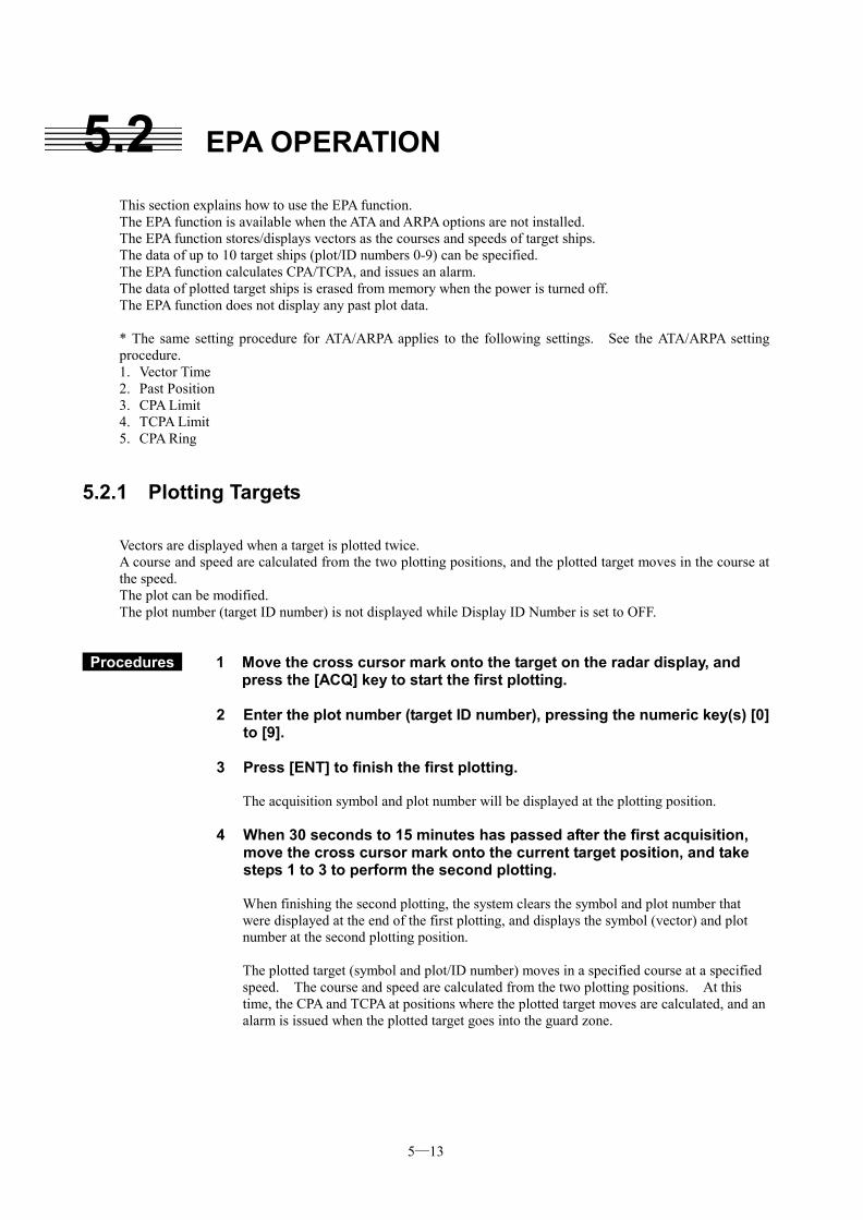
5─13
5.2 EPA OPERATION This section explains how to use the EPA function. The EPA function is available when the ATA and ARPA options are not installed. The EPA function stores/displays vectors as the courses and speeds of target ships. The data of up to 10 target ships (plot/ID numbers 0-9) can be specified. The EPA function calculates CPA/TCPA, and issues an alarm. The data of plotted target ships is erased from memory when the power is turned off. The EPA function does not display any past plot data. * The same setting procedure for ATA/ARPA applies to the following settings. See the ATA/ARPA setting procedure. 1. Vector Time 2. Past Position 3. CPA Limit 4. TCPA Limit 5. CPA Ring
5.2.1 Plotting Targets Vectors are displayed when a target is plotted twice. A course and speed are calculated from the two plotting positions, and the plotted target moves in the course at the speed. The plot can be modified. The plot number (target ID number) is not displayed while Display ID Number is set to OFF.
Procedures 1 Move the cross cursor mark onto the target on the radar display, and
press the [ACQ] key to start the first plotting. 2 Enter the plot number (target ID number), pressing the numeric key(s) [0]
to [9]. 3 Press [ENT] to finish the first plotting.
The acquisition symbol and plot number will be displayed at the plotting position.
4 When 30 seconds to 15 minutes has passed after the first acquisition,
move the cross cursor mark onto the current target position, and take steps 1 to 3 to perform the second plotting. When finishing the second plotting, the system clears the symbol and plot number that were displayed at the end of the first plotting, and displays the symbol (vector) and plot number at the second plotting position. The plotted target (symbol and plot/ID number) moves in a specified course at a specified speed. The course and speed are calculated from the two plotting positions. At this time, the CPA and TCPA at positions where the plotted target moves are calculated, and an alarm is issued when the plotted target goes into the guard zone.
5─14
5.2 EPA OPERATION ��
���
5
5.2.2 Modifying Plotted Target Data The system modifies specified plotted target data. It clears the specified data, and displays the plotted target immediately before it moves to the clear position until re-acquiring a target.
Procedures 1 Press the [ACQ] key.
2 Enter the plot number (target ID number) for modification, pressing the
numeric key(s) [0] to [9]. 3 Press the [CLR] key.
The previously updated status will be displayed. “M” is also displayed beside the mark, indicating that modification is in progress.
4 Move the cross cursor mark to the modification position to re-acquire a
target. At this time, specify the plot number you entered in step 2. ([ACQ], [0]-[9], [ENT])
5.2.3 Canceling Plotted Target Data The system cancels the display of specified plotted target data. Once plotted target data is canceled, it cannot be restored any more.
Procedures 1 Press the [ACQ] key.
2 Enter the plot number for cancellation, pressing the numeric key(s) [0] to
[9]. 3 Press the [TGT CNCL] key.
The plotted target data of the specified plot number will be canceled.
Canceling all plotted targets
Procedures 1 Hold down the [TGT CNCL] key for 5 seconds or more.
The plotted targets of all the plot numbers will be canceled.
5─15
5.2.4 Displaying Numeric Data of Plotted Targets The following data is displayed for a specified plotted target: TGT ID Plot number BRG Bearing: 0.1� unit RNG Range: 0.01 nm unit CRS Target’s true course: 0.1� unit SPD Target’s true speed: 0.1 knot unit CPA CPA: 0.01 nm unit TCPA TCPA: 0.1 min unit TIME Elapsed time: 0.1 min unit
Procedures 1 Press the [TGT DATA] key.
2 Enter the plot number pressing the numeric keys [0] to [9]. 3 Press [ENT] key.
The data of the specified plot number will be displayed. The mark of the target for which numeric data is displayed is changed into “□”.
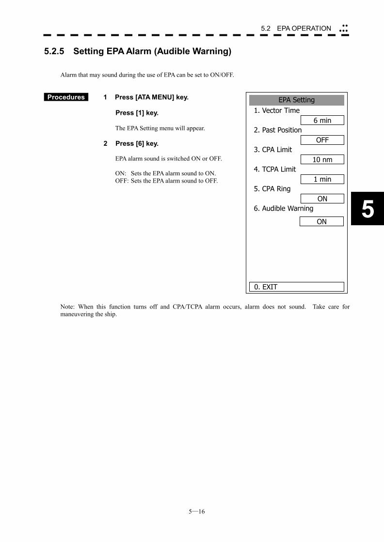
5─16
5.2 EPA OPERATION ��
���
5
EPA Setting1. Vector Time
6 min2. Past Position
OFF3. CPA Limit
10 nm4. TCPA Limit
1 min5. CPA Ring
ON6. Audible Warning
0. EXIT
ON
5.2.5 Setting EPA Alarm (Audible Warning)
Alarm that may sound during the use of EPA can be set to ON/OFF.
Procedures 1 Press [ATA MENU] key. Press [1] key.
The EPA Setting menu will appear. 2 Press [6] key.
EPA alarm sound is switched ON or OFF. ON: Sets the EPA alarm sound to ON. OFF: Sets the EPA alarm sound to OFF.
Note: When this function turns off and CPA/TCPA alarm occurs, alarm does not sound. Take care for maneuvering the ship.
5─17
��If untracked targets intrude into the guard zone in theconditions that maximum number of targets is under tracking, the targets acquired automatically will be cancelled in the order of lower levels of danger.
5.3 ATA/ARPA OPERATION This section explains how to use the ATA and ARPA functions. Each function is available only when the ATA or ARPA option is installed. The functions automatically track a target, and store/display vectors as the course and speed. They calculate CPA and TCPA, and issue an alarm. The basic operations of ATA and ARPA are the same, but available functions are different. The ATA function can track up to 30 ships; the ARPA function can track up to 100 ships. Both functions set a guard zone for automatic acquisition. The ARPA function permits the use of the trial maneuvering function (TRIAL). (The ATA does not.) When the power is turned off or the transmit/standby mode is activated, tracking data is erased from memory.
5.3.1 Acquiring Target
Target acquisition can be performed on two modes, AUTO and MANUAL, and both modes can be used at the same time.
Automatic Acquisition [AUTO]
Procedures 1 Press the [GZ ALARM] key. Automatic acquisition will be started. The mark “ ” and target ID number are put to an acquired target, and they move together with the target. The vectors are displayed within one minute.
2 Press the [GZ ALARM] key again.
Automatic acquisition will be turned off, and the guard zone disappears from the radar display. However, automatically acquired ships are continuously tracked. For the guard zone to be called by using the [GZ ALARM] key, refer to Section 5.1.6 Setting Automatic Acquisition Key Assignment.
* The guard zone can be called by using buttons and shown in the radar display on page 2-7.
Attention
49 50
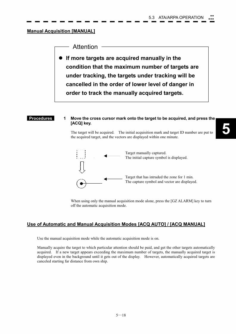
5─18
5.3 ATA/ARPA OPERATION ��
���
5
Manual Acquisition [MANUAL]
Procedures 1 Move the cross cursor mark onto the target to be acquired, and press the
[ACQ] key.
The target will be acquired. The initial acquisition mark and target ID number are put to the acquired target, and the vectors are displayed within one minute.
When using only the manual acquisition mode alone, press the [GZ ALARM] key to turn off the automatic acquisition mode.
Use of Automatic and Manual Acquisition Modes [ACQ AUTO] / [ACQ MANUAL] Use the manual acquisition mode while the automatic acquisition mode is on. Manually acquire the target to which particular attention should be paid, and get the other targets automatically acquired. If a new target appears exceeding the maximum number of targets, the manually acquired target is displayed even in the background until it gets out of the display. However, automatically acquired targets are canceled starting far distance from own ship.
��If more targets are acquired manually in the condition that the maximum number of targets are under tracking, the targets under tracking will be cancelled in the order of lower level of danger in order to track the manually acquired targets.
Attention
Target manually captured. The initial capture symbol is displayed.
Target that has intruded the zone for 1 min. The capture symbol and vector are displayed.
5─19
5.3.2 Canceling Unwanted Targets Unwanted targets can be canceled one by one in the following cases: �� Tracking is no longer necessary for targets with which vectors/symbols are displayed after being acquired
and tracked. �� The number of vectors on the radar display needs to be reduced for easy observation.
When targets are to be re-acquired from the beginning, all the current vectors can also be canceled.
Canceling targets one by one
Procedures 1 Move the cross cursor mark onto the target to be canceled.
2 Press the [TGT CNCL] key.
The target’s vectors and symbols will disappear, and only the radar video remains.
Canceling all targets collectively
Procedures 1 Hold down the [TGT CNCL] key.
The vectors and symbols of all the targets will disappear, and only the radar videos remain.
Note: When all the targets have been canceled, the system stops tracking them. Thus, you need to re-acquire
targets in manual or automatic acquisition mode. Do not cancel all the targets unless otherwise required.
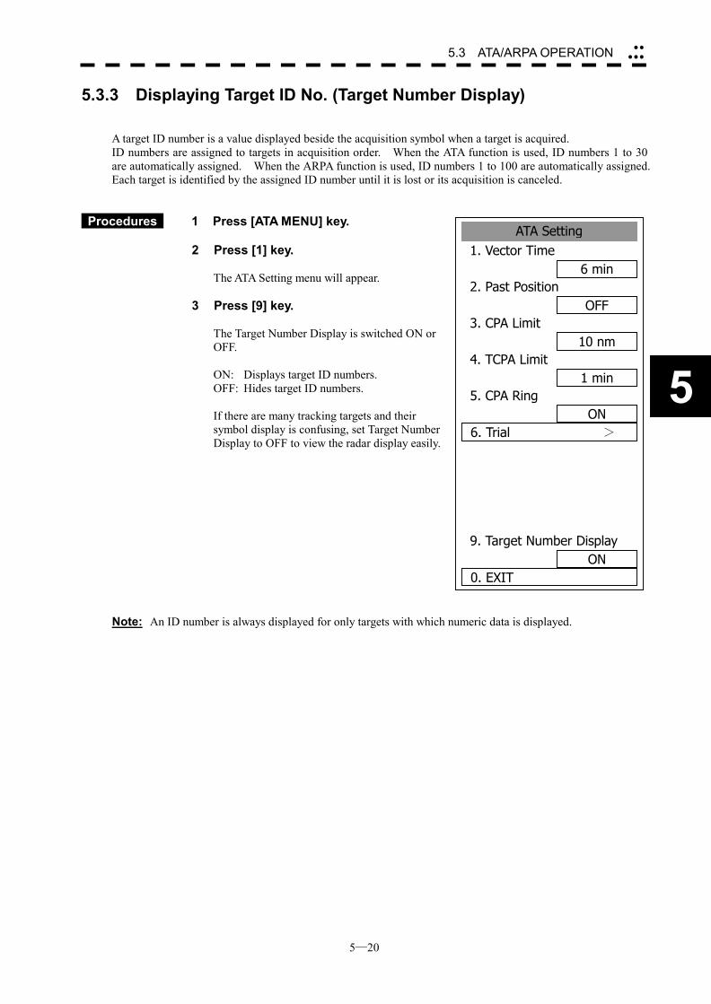
5─20
5.3 ATA/ARPA OPERATION ��
���
5
ATA Setting1. Vector Time
6 min2. Past Position
OFF3. CPA Limit
10 nm4. TCPA Limit
1 min5. CPA Ring
ON6. Trial >
9. Target Number DisplayON
0. EXIT
5.3.3 Displaying Target ID No. (Target Number Display) A target ID number is a value displayed beside the acquisition symbol when a target is acquired. ID numbers are assigned to targets in acquisition order. When the ATA function is used, ID numbers 1 to 30 are automatically assigned. When the ARPA function is used, ID numbers 1 to 100 are automatically assigned. Each target is identified by the assigned ID number until it is lost or its acquisition is canceled.
Procedures 1 Press [ATA MENU] key. 2 Press [1] key.
The ATA Setting menu will appear.
3 Press [9] key.
The Target Number Display is switched ON or OFF.
ON: Displays target ID numbers. OFF: Hides target ID numbers. If there are many tracking targets and their symbol display is confusing, set Target Number Display to OFF to view the radar display easily.
Note: An ID number is always displayed for only targets with which numeric data is displayed.
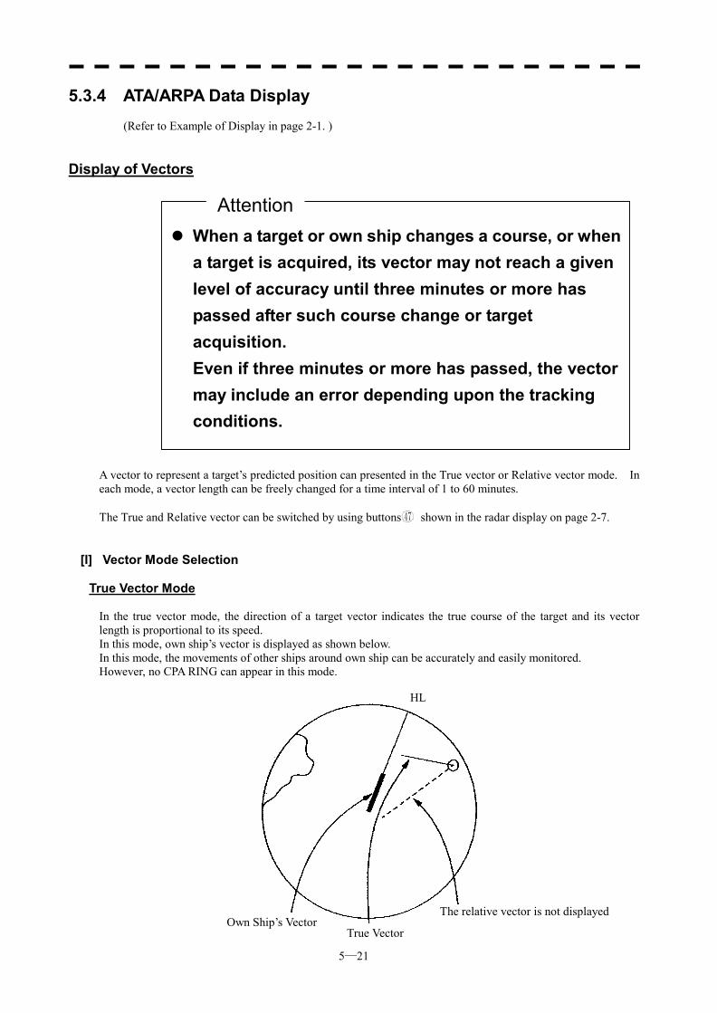
5─21
5.3.4 ATA/ARPA Data Display
(Refer to Example of Display in page 2-1. )
Display of Vectors A vector to represent a target’s predicted position can presented in the True vector or Relative vector mode. In each mode, a vector length can be freely changed for a time interval of 1 to 60 minutes. The True and Relative vector can be switched by using buttons 47 shown in the radar display on page 2-7.
[I] Vector Mode Selection
True Vector Mode In the true vector mode, the direction of a target vector indicates the true course of the target and its vector length is proportional to its speed. In this mode, own ship’s vector is displayed as shown below. In this mode, the movements of other ships around own ship can be accurately and easily monitored. However, no CPA RING can appear in this mode.
��When a target or own ship changes a course, or whena target is acquired, its vector may not reach a given level of accuracy until three minutes or more has passed after such course change or target acquisition. Even if three minutes or more has passed, the vector may include an error depending upon the tracking conditions.
Attention
Own Ship’s VectorTrue Vector
The relative vector is not displayed
HL
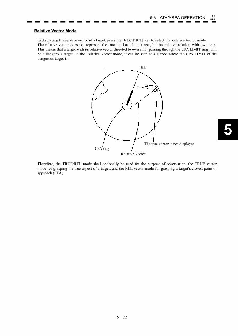
5─22
5.3 ATA/ARPA OPERATION ��
���
5
Relative Vector Mode In displaying the relative vector of a target, press the [VECT R/T] key to select the Relative Vector mode. The relative vector does not represent the true motion of the target, but its relative relation with own ship. This means that a target with its relative vector directed to own ship (passing through the CPA LIMIT ring) will be a dangerous target. In the Relative Vector mode, it can be seen at a glance where the CPA LIMIT of the dangerous target is.
Therefore, the TRUE/REL mode shall optionally be used for the purpose of observation: the TRUE vector mode for grasping the true aspect of a target, and the REL vector mode for grasping a target’s closest point of approach (CPA)
CPA ringRelative Vector
The true vector is not displayed
HL
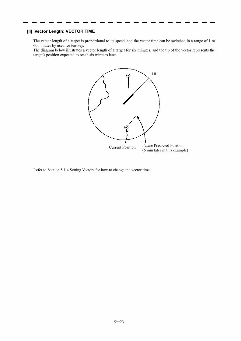
5─23
[II] Vector Length: VECTOR TIME The vector length of a target is proportional to its speed, and the vector time can be switched in a range of 1 to 60 minutes by used for ten-key. The diagram below illustrates a vector length of a target for six minutes, and the tip of the vector represents the target’s position expected to reach six minutes later.
Refer to Section 5.1.4 Setting Vectors for how to change the vector time.
Current Position Future Predicted Position (6 min later in this example)
HL
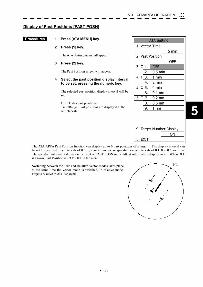
5─24
5.3 ATA/ARPA OPERATION ��
���
5
ATA Setting1. Vector Time
6 min2. Past Position
OFF3. CPA Limit
10 nm4. TCPA Limit
1 nm5. CPA Ring
ON6. TRIAL
9. Target Number DisplayON
0. EXIT
1. OFF2. 0.5 min3. 1 min4. 2 min5. 4 min6. 0.1 nm7. 0.2 nm8. 0.5 nm9. 1 nm
Display of Past Positions [PAST POSN]
Procedures 1 Press [ATA MENU] key.
2 Press [1] key.
The ATA Setting menu will appear.
3 Press [2] key.
The Past Position screen will appear.
4 Select the past position display interval to be set, pressing the numeric key. The selected past position display interval will be set.
OFF: Hides past positions. Time/Range: Past positions are displayed at the set intervals.
The ATA/ARPA Past Position function can display up to 6 past positions of a target. The display interval can be set to specified time intervals of 0.5, 1, 2, or 4 minutes, or specified range intervals of 0.1, 0.2, 0.5, or 1 nm. The specified interval is shown on the right of PAST POSN in the ARPA information display area. When OFF is shown, Past Position is set to OFF in the menu. Switching between the True and Relative Vector modes takes place at the same time the vector mode is switched. In relative mode, target’s relative tracks displayed.
HL
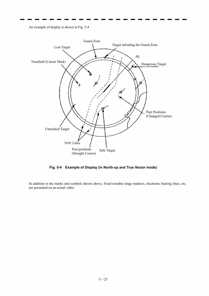
5─25
An example of display is shown in Fig. 5-4
Fig. 5-4 Example of Display (in North-up and True Vector mode)
In addition to the marks and symbols shown above, fixed/variable range markers, electronic bearing lines, etc. are presented on an actual video.
Trackball (Cursor Mark)
Lost Target
Guard ZoneTarget intruding the Guard Zone
Dangerous Target
Past Positions (Changed Course)
Safe TargetPast positions (Straight Course)
NAV Lines
Untracked Target
HL
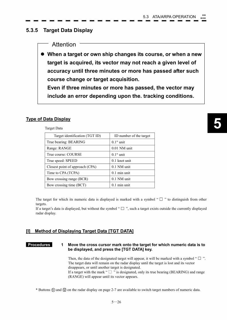
5─26
5.3 ATA/ARPA OPERATION ��
���
5
5.3.5 Target Data Display
Type of Data Display
Target Data
Target identification (TGT ID) ID number of the target True bearing: BEARING 0.1� unit Range: RANGE 0.01 NM unit
True course: COURSE 0.1� unit True speed: SPEED 0.1 knot unit Closest point of approach (CPA) 0.1 NM unit Time to CPA (TCPA) 0.1 min unit Bow crossing range (BCR) 0.1 NM unit Bow crossing time (BCT) 0.1 min unit
The target for which its numeric data is displayed is marked with a symbol “ ” to distinguish from other targets. If a target’s data is displayed, but without the symbol “ ”, such a target exists outside the currently displayed radar display.
[I] Method of Displaying Target Data [TGT DATA]
Procedures 1 Move the cross cursor mark onto the target for which numeric data is to be displayed, and press the [TGT DATA] key.
Then, the data of the designated target will appear, it will be marked with a symbol “ ”. The target data will remain on the radar display until the target is lost and its vector disappears, or until another target is designated. If a target with the mark “ ” is designated, only its true bearing (BEARING) and range (RANGE) will appear until its vector appears.
* Buttons and on the radar display on page 2-7 are available to switch target numbers of numeric data.
��When a target or own ship changes its course, or when a newtarget is acquired, its vector may not reach a given level of accuracy until three minutes or more has passed after such course change or target acquisition. Even if three minutes or more has passed, the vector may include an error depending upon the. tracking conditions.
Attention
51 52
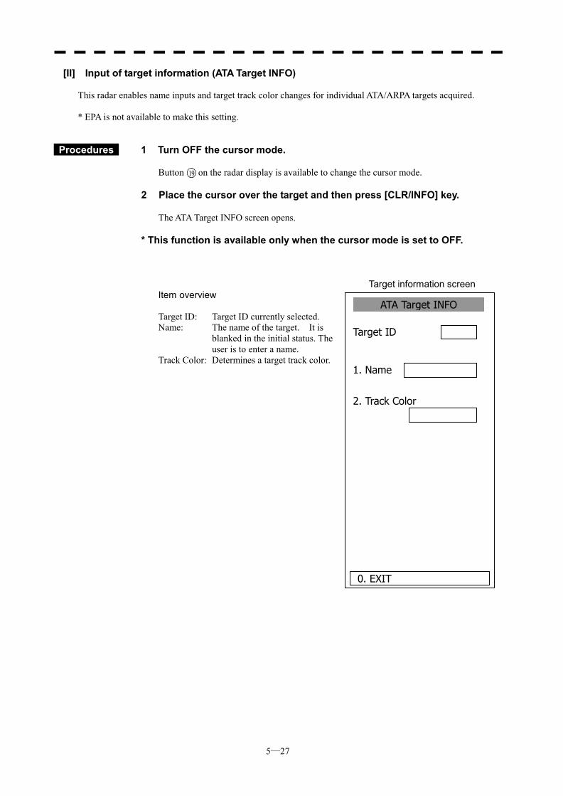
5─27
ATA Target INFO
1. Name
2. Track Color
Target ID
0. EXIT
[II] Input of target information (ATA Target INFO)
This radar enables name inputs and target track color changes for individual ATA/ARPA targets acquired. * EPA is not available to make this setting.
Procedures 1 Turn OFF the cursor mode.
Button on the radar display is available to change the cursor mode. 2 Place the cursor over the target and then press [CLR/INFO] key.
The ATA Target INFO screen opens. * This function is available only when the cursor mode is set to OFF.
Target information screen Item overview Target ID: Target ID currently selected. Name: The name of the target. It is
blanked in the initial status. The user is to enter a name.
Track Color: Determines a target track color.
19
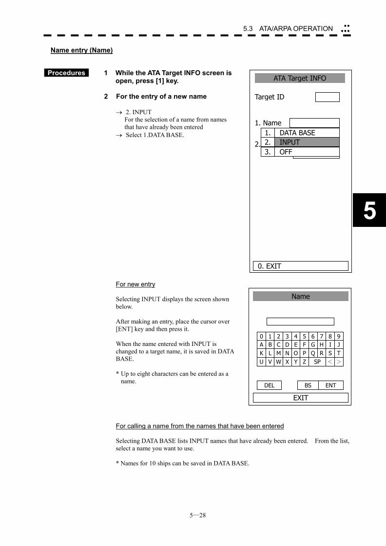
5─28
5.3 ATA/ARPA OPERATION ��
���
5
Name entry (Name)
Procedures 1 While the ATA Target INFO screen is open, press [1] key.
2 For the entry of a new name
� 2. INPUT For the selection of a name from names
that have already been entered � Select 1.DATA BASE. For new entry Selecting INPUT displays the screen shown below. After making an entry, place the cursor over [ENT] key and then press it. When the name entered with INPUT is changed to a target name, it is saved in DATA BASE. * Up to eight characters can be entered as a
name. For calling a name from the names that have been entered Selecting DATA BASE lists INPUT names that have already been entered. From the list, select a name you want to use. * Names for 10 ships can be saved in DATA BASE.
1 2 3 4 5 6 7 8 90 B C D E F G H I JA L M N O P Q R S TK V W X Y Z SP < >U
DEL ENT BS
Name
EXIT
ATA Target INFO
1. Name
2. Track Color
Target ID
0. EXIT
1. DATA BASE2. INPUT3. OFF
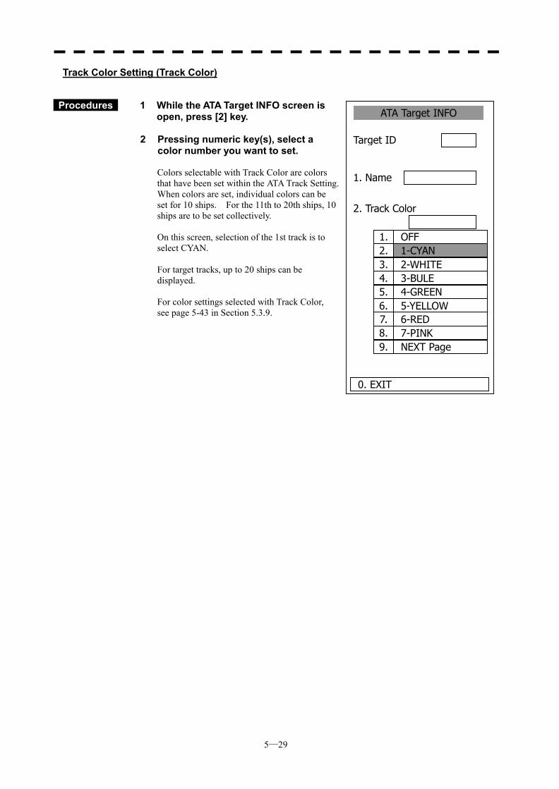
5─29
1. OFF2. 1-CYAN3. 2-WHITE4. 3-BULE5. 4-GREEN6. 5-YELLOW7. 6-RED8. 7-PINK9. NEXT Page
ATA Target INFO
1. Name
2. Track Color
Target ID
0. EXIT
Track Color Setting (Track Color)
Procedures 1 While the ATA Target INFO screen is open, press [2] key.
2 Pressing numeric key(s), select a
color number you want to set. Colors selectable with Track Color are colors that have been set within the ATA Track Setting. When colors are set, individual colors can be set for 10 ships. For the 11th to 20th ships, 10 ships are to be set collectively. On this screen, selection of the 1st track is to select CYAN. For target tracks, up to 20 ships can be displayed. For color settings selected with Track Color, see page 5-43 in Section 5.3.9.
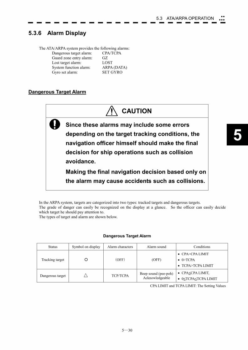
5─30
5.3 ATA/ARPA OPERATION ��
���
5
5.3.6 Alarm Display
The ATA/ARPA system provides the following alarms: Dangerous target alarm: CPA/TCPA Guard zone entry alarm: GZ Lost target alarm: LOST System function alarm: ARPA (DATA) Gyro set alarm: SET GYRO
Dangerous Target Alarm
CAUTION
Since these alarms may include some errors depending on the target tracking conditions, the navigation officer himself should make the final decision for ship operations such as collision avoidance.
Making the final navigation decision based only on the alarm may cause accidents such as collisions.
In the ARPA system, targets are categorized into two types: tracked targets and dangerous targets. The grade of danger can easily be recognized on the display at a glance. So the officer can easily decide which target he should pay attention to. The types of target and alarm are shown below.
Dangerous Target Alarm
Status Symbol on display Alarm characters Alarm sound Conditions
Tracking target � (OFF) (OFF) �� CPA>CPA LIMIT �� 0>TCPA �� TCPA>TCPA LIMIT
Dangerous target TCP/TCPA Beep sound (pee-poh) Acknowledgeable
�� CPA�CPA LIMIT, �� 0�TCPA�TCPA LIMIT
CPA LIMIT and TCPA LIMIT: The Setting Values
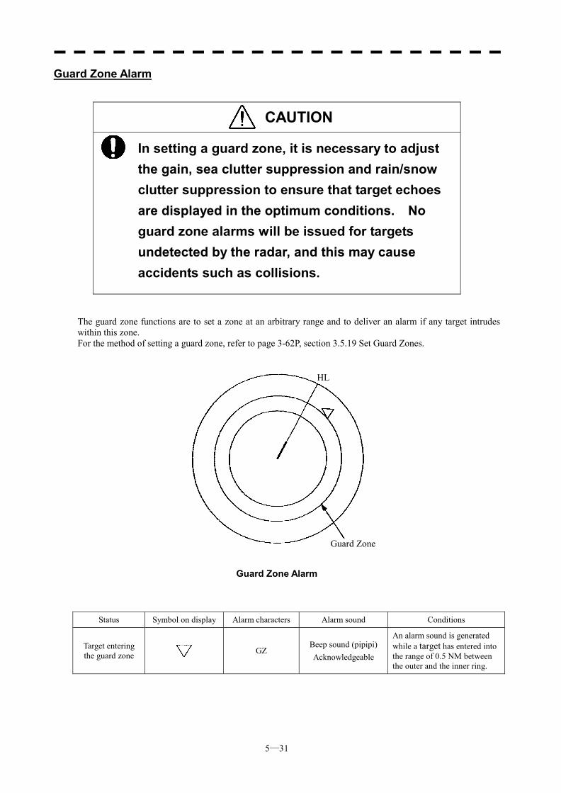
5─31
Guard Zone Alarm
CAUTION
In setting a guard zone, it is necessary to adjust the gain, sea clutter suppression and rain/snow clutter suppression to ensure that target echoes are displayed in the optimum conditions. No guard zone alarms will be issued for targets undetected by the radar, and this may cause accidents such as collisions.
The guard zone functions are to set a zone at an arbitrary range and to deliver an alarm if any target intrudes within this zone. For the method of setting a guard zone, refer to page 3-62P, section 3.5.19 Set Guard Zones.
Guard Zone Alarm
Status Symbol on display Alarm characters Alarm sound Conditions
Target entering the guard zone GZ
Beep sound (pipipi) Acknowledgeable
An alarm sound is generated while a target has entered into the range of 0.5 NM between the outer and the inner ring.
Guard Zone
HL
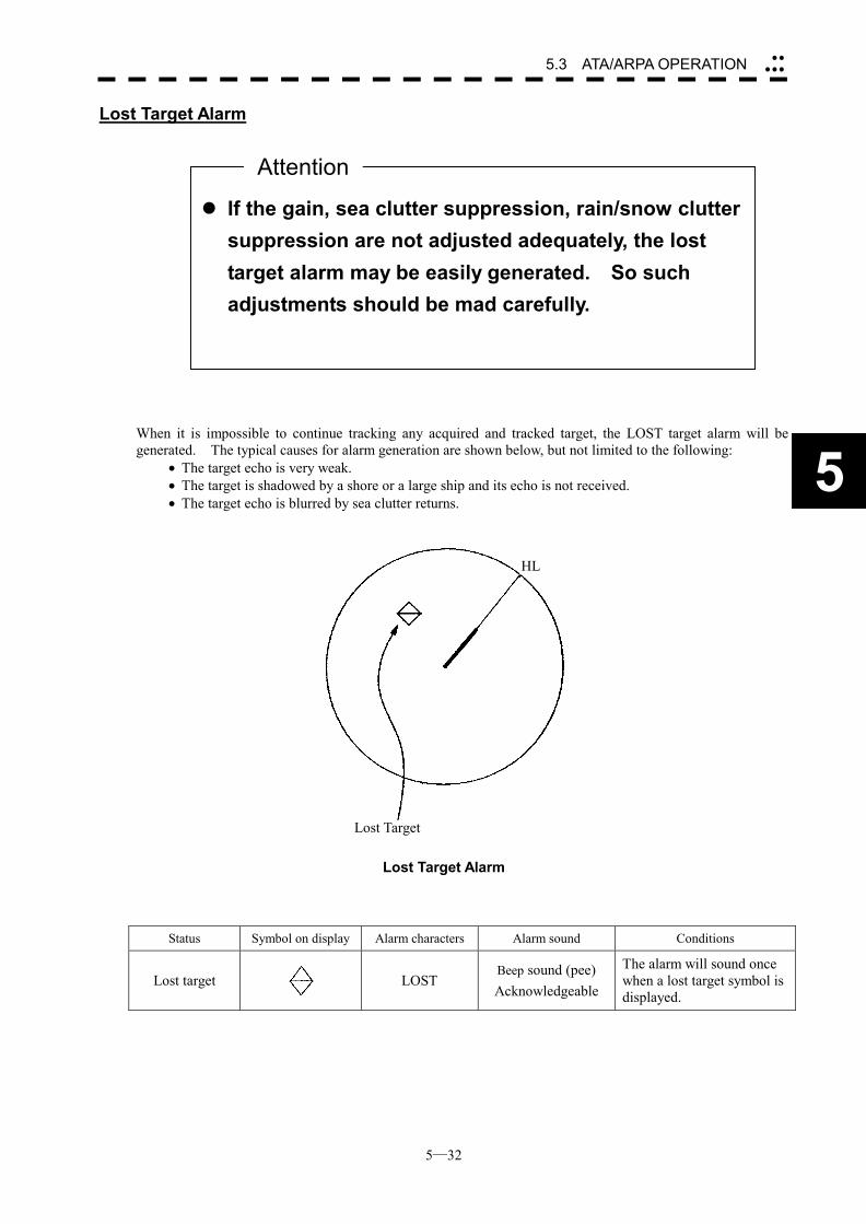
5─32
5.3 ATA/ARPA OPERATION ��
���
5
Lost Target Alarm When it is impossible to continue tracking any acquired and tracked target, the LOST target alarm will be generated. The typical causes for alarm generation are shown below, but not limited to the following:
�� The target echo is very weak. �� The target is shadowed by a shore or a large ship and its echo is not received. �� The target echo is blurred by sea clutter returns.
Lost Target Alarm
Status Symbol on display Alarm characters Alarm sound Conditions
Lost target
LOST Beep sound (pee) Acknowledgeable
The alarm will sound once when a lost target symbol is displayed.
��If the gain, sea clutter suppression, rain/snow clutter suppression are not adjusted adequately, the lost target alarm may be easily generated. So such adjustments should be mad carefully.
Attention
Lost Target
HL
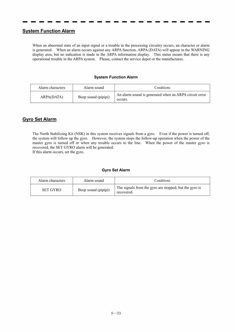
5─33
System Function Alarm
When an abnormal state of an input signal or a trouble in the processing circuitry occurs, an character or alarm is generated. When an alarm occurs against any ARPA function, ARPA (DATA) will appear in the WARNING display area, but no indication is made in the ARPA information display. This status means that there is any operational trouble in the ARPA system. Please, contact the service depot or the manufactures.
System Function Alarm
Alarm characters Alarm sound Conditions
ARPA(DATA) Beep sound (pipipi) An alarm sound is generated when an ARPA circuit error occurs.
Gyro Set Alarm
The North Stabilizing Kit (NSK) in this system receives signals from a gyro. Even if the power is turned off, the system will follow up the gyro. However, the system stops the follow-up operation when the power of the master gyro is turned off or when any trouble occurs to the line. When the power of the master gyro is recovered, the SET GYRO alarm will be generated. If this alarm occurs, set the gyro.
Gyro Set Alarm
Alarm characters Alarm sound Conditions
SET GYRO Beep sound (pipipi) The signals from the gyro are stopped, but the gyro is recovered.
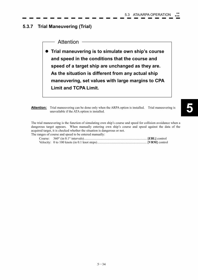
5─34
5.3 ATA/ARPA OPERATION ��
���
5
5.3.7 Trial Maneuvering (Trial) Attention: Trial maneuvering can be done only when the ARPA option is installed. Trial maneuvering is
unavailable if the ATA option is installed. The trial maneuvering is the function of simulating own ship’s course and speed for collision avoidance when a dangerous target appears. When manually entering own ship’s course and speed against the data of the acquired target, it is checked whether the situation is dangerous or not. The ranges of course and speed to be entered manually:
Course: 360� (in 0.1� intervals)........................................................................... [EBL] control Velocity: 0 to 100 knots (in 0.1 knot steps)........................................................... [VRM] control
��Trial maneuvering is to simulate own ship’s course and speed in the conditions that the course and speed of a target ship are unchanged as they are. As the situation is different from any actual ship maneuvering, set values with large margins to CPA Limit and TCPA Limit.
Attention
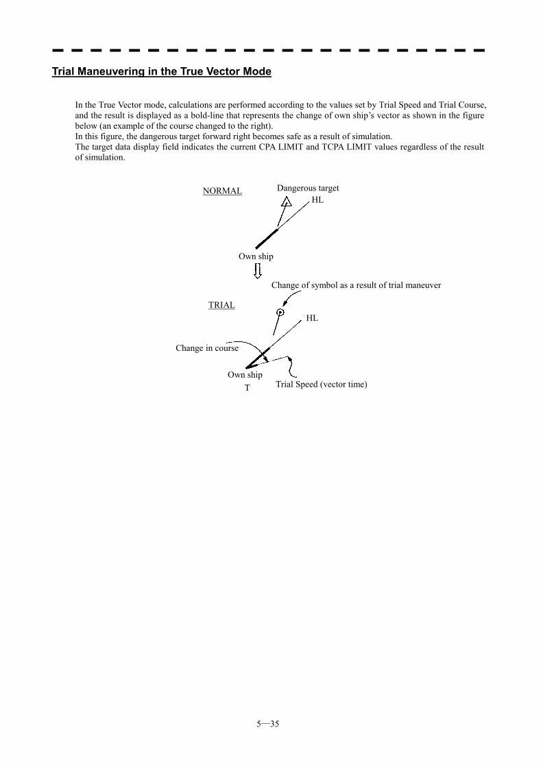
5─35
Trial Maneuvering in the True Vector Mode
In the True Vector mode, calculations are performed according to the values set by Trial Speed and Trial Course, and the result is displayed as a bold-line that represents the change of own ship’s vector as shown in the figure below (an example of the course changed to the right). In this figure, the dangerous target forward right becomes safe as a result of simulation. The target data display field indicates the current CPA LIMIT and TCPA LIMIT values regardless of the result of simulation.
Dangerous target
Own ship
Change of symbol as a result of trial maneuver
Change in course
Trial Speed (vector time) Own ship
HL
HL TRIAL
NORMAL
T
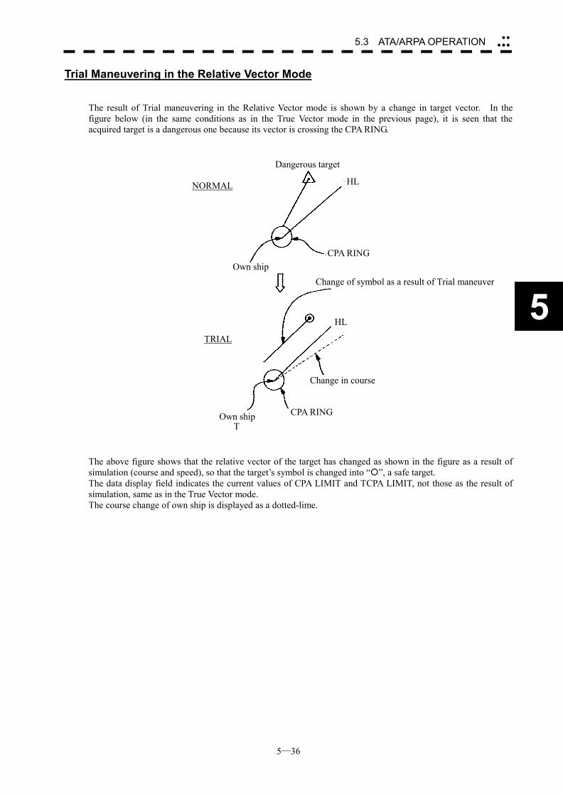
5─36
5.3 ATA/ARPA OPERATION ��
���
5
Trial Maneuvering in the Relative Vector Mode The result of Trial maneuvering in the Relative Vector mode is shown by a change in target vector. In the figure below (in the same conditions as in the True Vector mode in the previous page), it is seen that the acquired target is a dangerous one because its vector is crossing the CPA RING.
The above figure shows that the relative vector of the target has changed as shown in the figure as a result of simulation (course and speed), so that the target’s symbol is changed into “�”, a safe target. The data display field indicates the current values of CPA LIMIT and TCPA LIMIT, not those as the result of simulation, same as in the True Vector mode. The course change of own ship is displayed as a dotted-lime.
Dangerous target
Own shipChange of symbol as a result of Trial maneuver
Change in course
Own ship
HL
HL
TRIAL
NORMAL
T
CPA RING
CPA RING
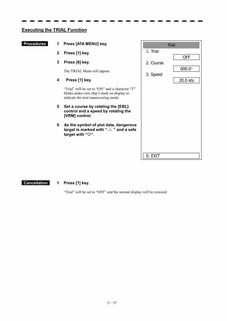
5─37
Trial1. Trial
OFF2. Course
000.0�3. Speed
20.0 kts
0. EXIT
Executing the TRIAL Function
Procedures 1 Press [ATA MENU] key.
2 Press [1] key. 3 Press [6] key.
The TRIAL Menu will appear.
4 Press [1] key.
“Trial” will be set to “ON” and a character “T” blinks under own ship’s mark on display to indicate the trial maneuvering mode.
5 Set a course by rotating the [EBL]
control and a speed by rotating the [VRM] control.
6 As the symbol of plot data, dangerous
target is marked with “ ” and a safe target with “�“.
Cancellation 1 Press [1] key.
“Trial” will be set to “OFF” and the normal display will be restored.
5─38
5.3 ATA/ARPA OPERATION ��
���
5
5.3.8 ATA/ARPA Simulation
CAUTION
Simulation is a function to check whether the ATA/ARPA system is operating normally. Do not use this function except when checking the ATA/ARPA operation. In particular, if this mode is used during navigation, pseudo targets appear on the radar display, which may be confused with the actual targets. Do not use this mode during navigation. Otherwise, this may cause accidents.
The following simulation to be used for ATA/ARPA can be referred to and modified: [I] Test Video: Test video for use in checking the operation of the target detection circuit. [II] ATA Simulator: Pseudo targets are generated on the radar display to check whether the ARPA
functions are operating normally. [III] Status: Displays the ATA status. [IV] Gate Display: Gate size to acquire and track targets.
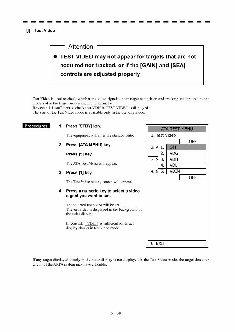
5─39
ATA TEST MENU1. Test Video
OFF2. ATA Simulator
OFF3. Status
4. Gate DisplayOFF
0. EXIT
OFF1. VDG2. VDH3. VDL4. VDIN5.
[I] Test Video Test Video is used to check whether the video signals under target acquisition and tracking are inputted to and processed in the target processing circuit normally. However, it is sufficient to check that VDH in TEST VIDEO is displayed. The start of the Test Video mode is available only in the Standby mode.
Procedures 1 Press [STBY] key.
The equipment will enter the standby state.
2 Press [ATA MENU] key.
Press [5] key.
The ATA Test Menu will appear.
3 Press [1] key.
The Test Video setting screen will appear.
4 Press a numeric key to select a video signal you want to set.
The selected test video will be set. The test video is displayed in the background of the radar display. In general, VDH is sufficient for target display checks in test video mode.
If any target displayed clearly in the radar display is not displayed in the Test Video mode, the target detection circuit of the ARPA system may have a trouble.
��TEST VIDEO may not appear for targets that are not acquired nor tracked, or if the [GAIN] and [SEA] controls are adjusted properly
Attention
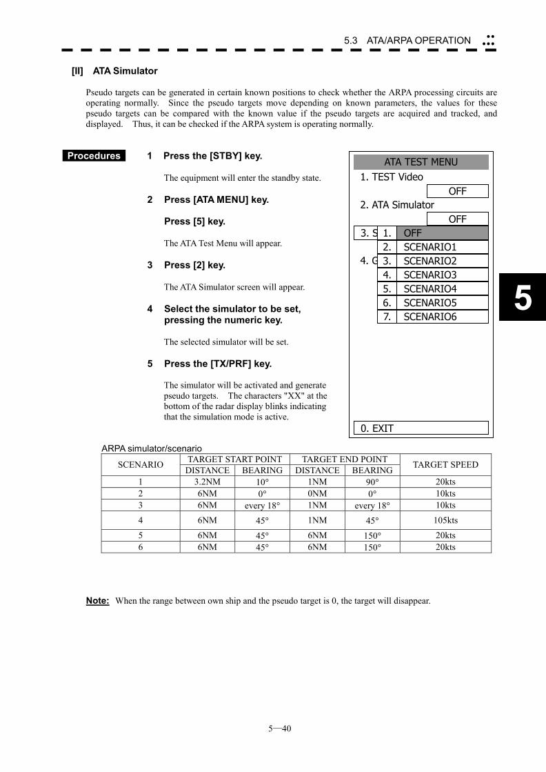
5─40
5.3 ATA/ARPA OPERATION ��
���
5
ATA TEST MENU1. TEST Video
OFF2. ATA Simulator
OFF3. Status
4. Gate DisplayOFF
0. EXIT
OFF1.SCENARIO12.SCENARIO23.SCENARIO34.SCENARIO45.SCENARIO56.SCENARIO67.
[II] ATA Simulator Pseudo targets can be generated in certain known positions to check whether the ARPA processing circuits are operating normally. Since the pseudo targets move depending on known parameters, the values for these pseudo targets can be compared with the known value if the pseudo targets are acquired and tracked, and displayed. Thus, it can be checked if the ARPA system is operating normally.
Procedures 1 Press the [STBY] key.
The equipment will enter the standby state.
2 Press [ATA MENU] key.
Press [5] key.
The ATA Test Menu will appear. 3 Press [2] key.
The ATA Simulator screen will appear. 4 Select the simulator to be set,
pressing the numeric key.
The selected simulator will be set. 5 Press the [TX/PRF] key.
The simulator will be activated and generate pseudo targets. The characters "XX" at the bottom of the radar display blinks indicating that the simulation mode is active.
ARPA simulator/scenario TARGET START POINT TARGET END POINT SCENARIO DISTANCE BEARING DISTANCE BEARING TARGET SPEED
1 3.2NM 10� 1NM 90� 20kts 2 6NM 0� 0NM 0� 10kts 3 6NM every 18� 1NM every 18� 10kts
4 6NM 45� 1NM 45� 105kts
5 6NM 45� 6NM 150� 20kts 6 6NM 45� 6NM 150� 20kts
Note: When the range between own ship and the pseudo target is 0, the target will disappear.

5─41
Procedures 1 Press the [STBY] key.
The equipment will enter the standby state.
2 Press [2] key while the ATA Test Menu is open.
The ATA Simulator screen will appear.
3 Press [1] key to select OFF. The ATA Simulator is turned off.
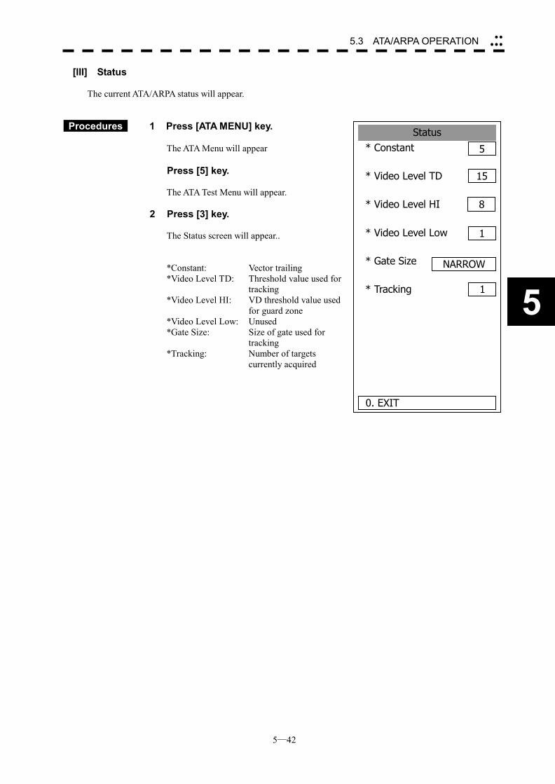
5─42
5.3 ATA/ARPA OPERATION ��
���
5
Status* Constant 5
* Video Level TD
* Video Level HI
* Video Level Low
* Gate Size
* Tracking
0. EXIT
15
8
1
NARROW
1
[III] Status The current ATA/ARPA status will appear.
Procedures 1 Press [ATA MENU] key.
The ATA Menu will appear
Press [5] key.
The ATA Test Menu will appear.
2 Press [3] key. The Status screen will appear..
*Constant: Vector trailing *Video Level TD: Threshold value used for
tracking *Video Level HI: VD threshold value used
for guard zone *Video Level Low: Unused *Gate Size: Size of gate used for
tracking *Tracking: Number of targets
currently acquired
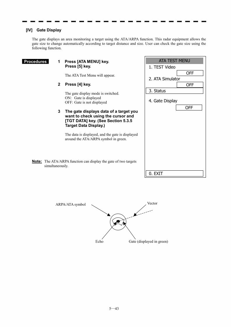
5─43
ATA TEST MENU1. TEST Video
OFF2. ATA Simulator
OFF3. Status
4. Gate Display
OFF
0. EXIT
[IV] Gate Display The gate displays an area monitoring a target using the ATA/ARPA function. This radar equipment allows the gate size to change automatically according to target distance and size. User can check the gate size using the following function.
Procedures 1 Press [ATA MENU] key. Press [5] key.
The ATA Test Menu will appear.
2 Press [4] key. The gate display mode is switched. ON: Gate is displayed OFF: Gate is not displayed
3 The gate displays data of a target you want to check using the cursor and [TGT DATA] key. (See Section 5.3.5 Target Data Display.) The data is displayed, and the gate is displayed around the ATA/ARPA symbol in green.
Note: The ATA/ARPA function can display the gate of two targets
simultaneously.
ARPA/ATA symbol Vector
Echo Gate (displayed in green)
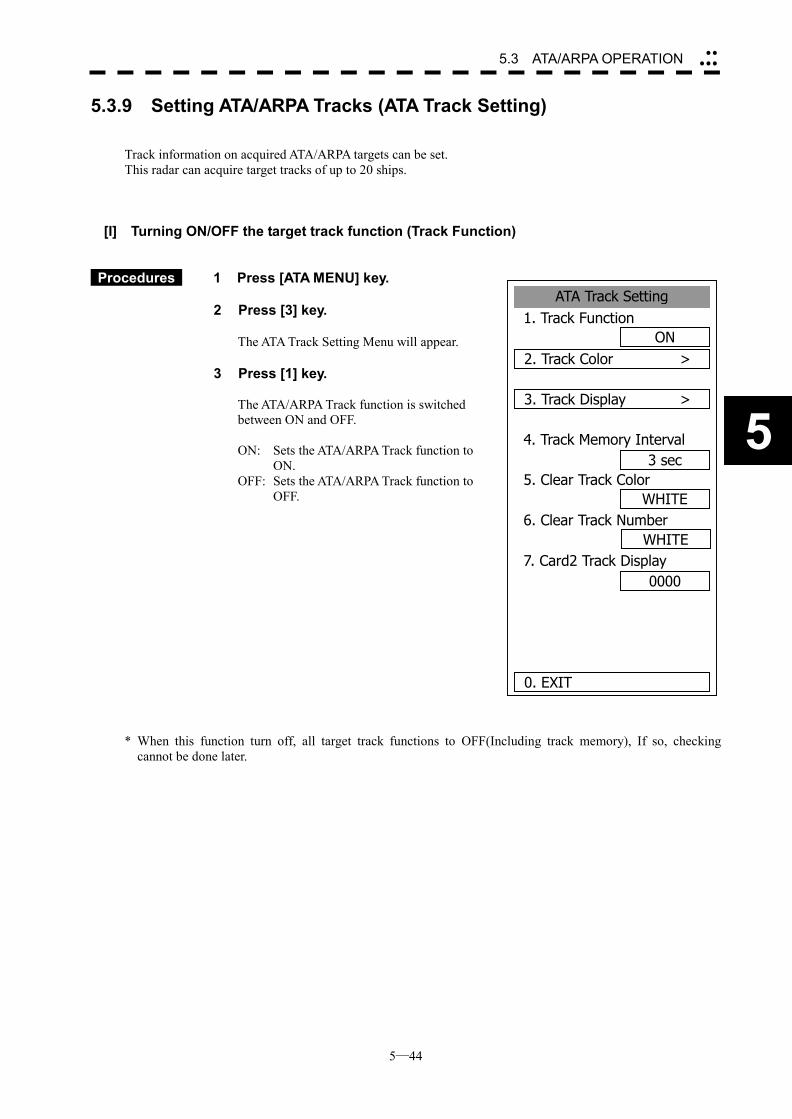
5─44
5.3 ATA/ARPA OPERATION ��
���
5
ATA Track Setting1. Track Function
ON2. Track Color >
3. Track Display >
4. Track Memory Interval3 sec
5. Clear Track ColorWHITE
6. Clear Track Number
7. Card2 Track Display0000
0. EXIT
WHITE
5.3.9 Setting ATA/ARPA Tracks (ATA Track Setting) Track information on acquired ATA/ARPA targets can be set. This radar can acquire target tracks of up to 20 ships.
[I] Turning ON/OFF the target track function (Track Function)
Procedures 1 Press [ATA MENU] key.
2 Press [3] key.
The ATA Track Setting Menu will appear. 3 Press [1] key.
The ATA/ARPA Track function is switched between ON and OFF. ON: Sets the ATA/ARPA Track function to
ON. OFF: Sets the ATA/ARPA Track function to
OFF.
* When this function turn off, all target track functions to OFF(Including track memory), If so, checking cannot be done later.
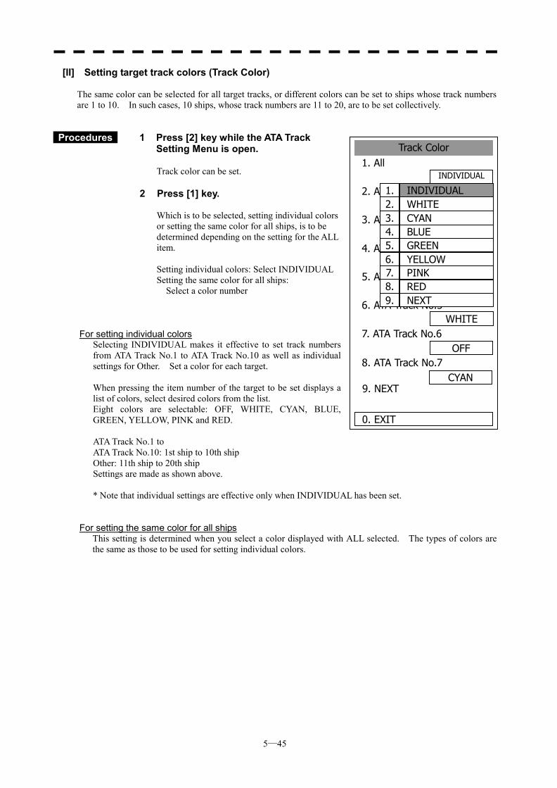
5─45
Track Color1. All
2. ATA Track No.1
3. ATA Track No.2
4. ATA Track No.3PINK
5. ATA Track No.4RED
6. ATA Track No.5
7. ATA Track No.6OFF
0. EXIT
WHITE
8. ATA Track No.7
9. NEXT
INDIVIDUAL
YELLOW
GREEN
CYAN
1. INDIVIDUAL2. WHITE3. CYAN4. BLUE5. GREEN6. YELLOW 7. PINK 8. RED 9. NEXT
[II] Setting target track colors (Track Color) The same color can be selected for all target tracks, or different colors can be set to ships whose track numbers are 1 to 10. In such cases, 10 ships, whose track numbers are 11 to 20, are to be set collectively.
Procedures 1 Press [2] key while the ATA Track
Setting Menu is open.
Track color can be set.
2 Press [1] key.
Which is to be selected, setting individual colors or setting the same color for all ships, is to be determined depending on the setting for the ALL item. Setting individual colors: Select INDIVIDUAL Setting the same color for all ships: Select a color number
For setting individual colors Selecting INDIVIDUAL makes it effective to set track numbers
from ATA Track No.1 to ATA Track No.10 as well as individual settings for Other. Set a color for each target.
When pressing the item number of the target to be set displays a
list of colors, select desired colors from the list. Eight colors are selectable: OFF, WHITE, CYAN, BLUE,
GREEN, YELLOW, PINK and RED. ATA Track No.1 to ATA Track No.10: 1st ship to 10th ship Other: 11th ship to 20th ship Settings are made as shown above.
* Note that individual settings are effective only when INDIVIDUAL has been set.
For setting the same color for all ships
This setting is determined when you select a color displayed with ALL selected. The types of colors are the same as those to be used for setting individual colors.
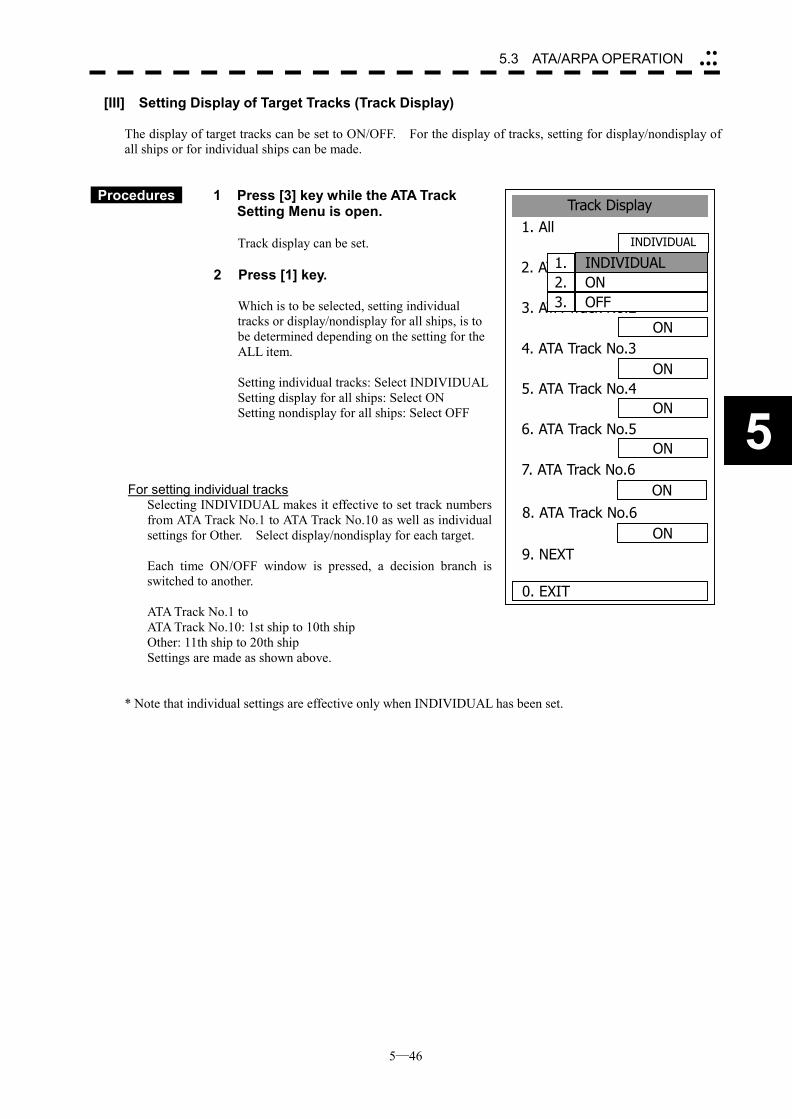
5─46
5.3 ATA/ARPA OPERATION ��
���
5
Track Display1. All
2. ATA Track No.1
3. ATA Track No.2
4. ATA Track No.3ON
5. ATA Track No.4ON
6. ATA Track No.5
7. ATA Track No.6ON
0. EXIT
ON
8. ATA Track No.6ON
9. NEXT
ON
ON
INDIVIDUAL
1. INDIVIDUAL2. ON3. OFF
[III] Setting Display of Target Tracks (Track Display) The display of target tracks can be set to ON/OFF. For the display of tracks, setting for display/nondisplay of all ships or for individual ships can be made.
Procedures 1 Press [3] key while the ATA Track Setting Menu is open.
Track display can be set.
2 Press [1] key.
Which is to be selected, setting individual tracks or display/nondisplay for all ships, is to be determined depending on the setting for the ALL item. Setting individual tracks: Select INDIVIDUAL Setting display for all ships: Select ON Setting nondisplay for all ships: Select OFF
For setting individual tracks Selecting INDIVIDUAL makes it effective to set track numbers
from ATA Track No.1 to ATA Track No.10 as well as individual settings for Other. Select display/nondisplay for each target.
Each time ON/OFF window is pressed, a decision branch is
switched to another. ATA Track No.1 to ATA Track No.10: 1st ship to 10th ship Other: 11th ship to 20th ship Settings are made as shown above.
* Note that individual settings are effective only when INDIVIDUAL has been set.
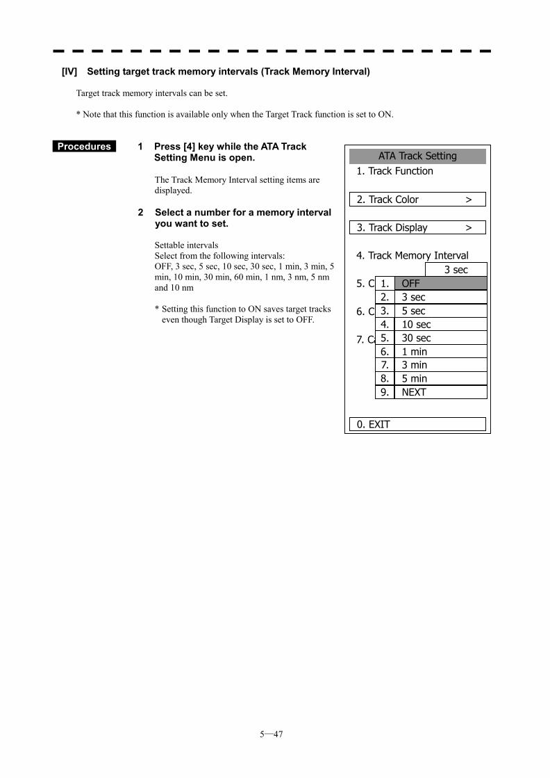
5─47
ATA Track Setting1. Track Function
2. Track Color >
3. Track Display >
4. Track Memory Interval3 sec
5. Clear Track ColorWHITE
6. Clear Track Number
7. Card2 Track Display0000
0. EXIT
0000
1. OFF2. 3 sec3. 5 sec4. 10 sec5. 30 sec6. 1 min7. 3 min8. 5 min9. NEXT
[IV] Setting target track memory intervals (Track Memory Interval) Target track memory intervals can be set. * Note that this function is available only when the Target Track function is set to ON.
Procedures 1 Press [4] key while the ATA Track Setting Menu is open.
The Track Memory Interval setting items are displayed.
2 Select a number for a memory interval
you want to set.
Settable intervals Select from the following intervals: OFF, 3 sec, 5 sec, 10 sec, 30 sec, 1 min, 3 min, 5 min, 10 min, 30 min, 60 min, 1 nm, 3 nm, 5 nm and 10 nm * Setting this function to ON saves target tracks
even though Target Display is set to OFF.
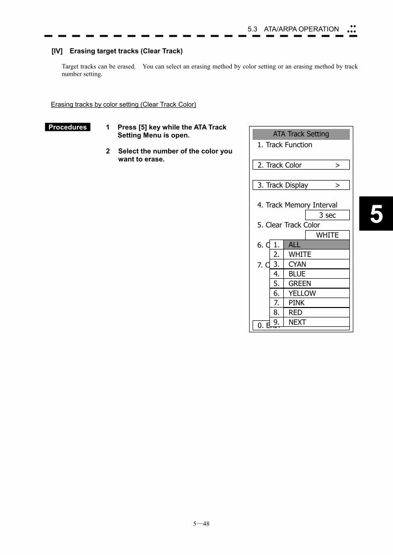
5─48
5.3 ATA/ARPA OPERATION ��
���
5
ATA Track Setting1. Track Function
2. Track Color >
3. Track Display >
4. Track Memory Interval3 sec
5. Clear Track Color
6. Clear Track Number
7. Card2 Track Display0000
0. EXIT
WHITE
WHITE1. ALL2. WHITE3. CYAN4. BLUE5. GREEN6. YELLOW7. PINK8. RED9. NEXT
[IV] Erasing target tracks (Clear Track) Target tracks can be erased. You can select an erasing method by color setting or an erasing method by track number setting.
Erasing tracks by color setting (Clear Track Color)
Procedures 1 Press [5] key while the ATA Track Setting Menu is open.
2 Select the number of the color you
want to erase.
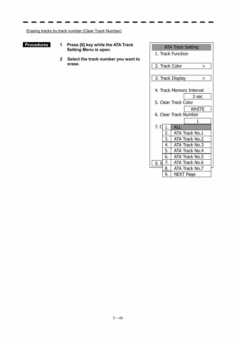
5─49
ATA Track Setting1. Track Function
2. Track Color >
3. Track Display >
4. Track Memory Interval3 sec
5. Clear Track Color
6. Clear Track Number
7. Card2 Track Display0000
0. EXIT
WHITE
11. ALL2. ATA Track No.13. ATA Track No.24. ATA Track No.35. ATA Track No.46. ATA Track No.57. ATA Track No.68. ATA Track No.79. NEXT Page
Erasing tracks by track number (Clear Track Number)
Procedures 1 Press [6] key while the ATA Track Setting Menu is open.
2 Select the track number you want to
erase.
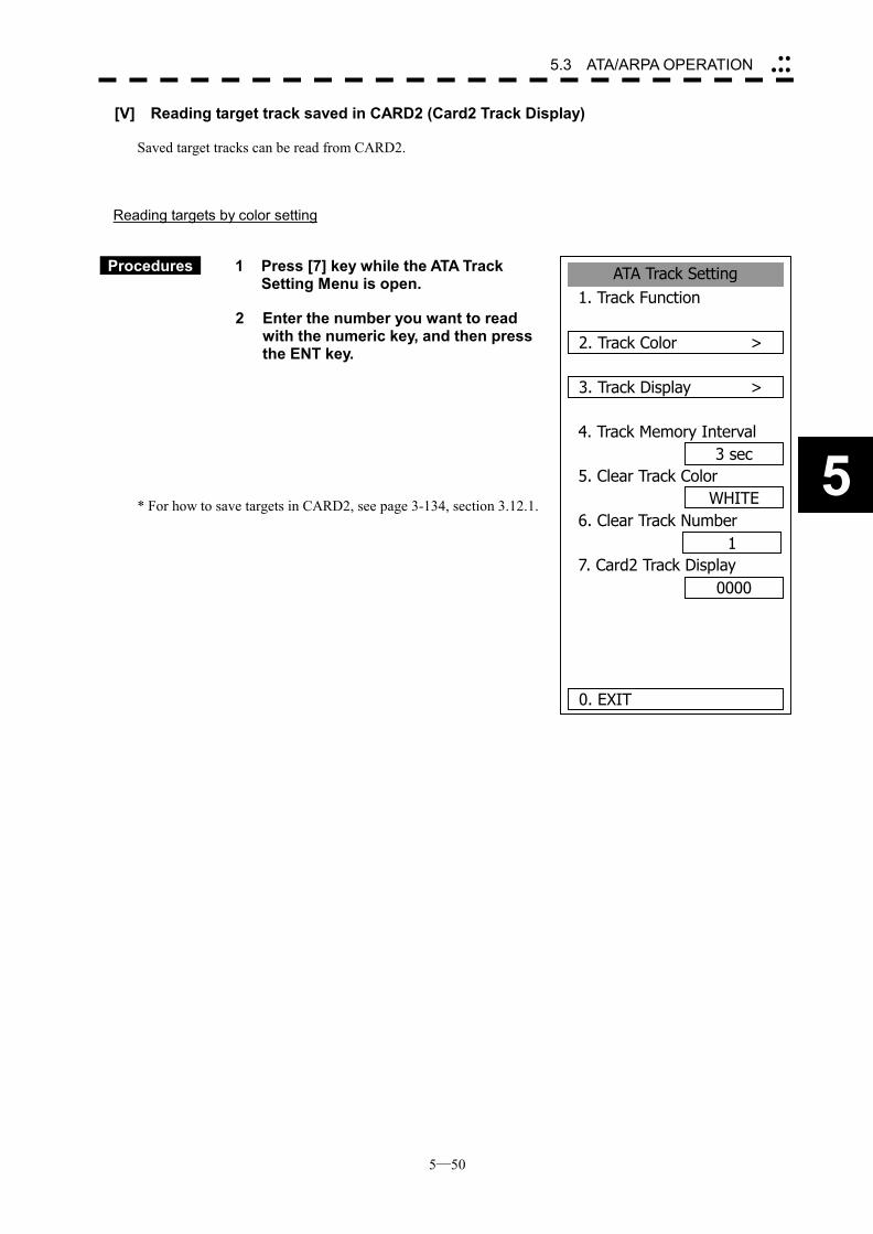
5─50
5.3 ATA/ARPA OPERATION ��
���
5
ATA Track Setting1. Track Function
2. Track Color >
3. Track Display >
4. Track Memory Interval3 sec
5. Clear Track Color
6. Clear Track Number
7. Card2 Track Display0000
0. EXIT
WHITE
1
[V] Reading target track saved in CARD2 (Card2 Track Display) Saved target tracks can be read from CARD2.
Reading targets by color setting
Procedures 1 Press [7] key while the ATA Track Setting Menu is open.
2 Enter the number you want to read
with the numeric key, and then press the ENT key.
* For how to save targets in CARD2, see page 3-134, section 3.12.1.
5─51
5.4 AIS OPERATION * Use of this function requires AIS I/F (option).
There are the following limitations on use of the AIS function, system, and operation: [I] This system can display a maximum of 50 AIS targets. There
are two types of filters for increasing the display priority. (Refer to Section 5.4.6 AIS FILTER SETTING.)
[II] Keep in mind that the following restrictions are placed on useof the AIS function: 1) The AIS function cannot be turned on in the following cases:
� MANUAL is selected for the speed sensor. � LOG or 2-axis LOG is used for the speed sensor, and SET
and DRIFT are selected. 2) LOG or 2-axis LOG cannot be selected for the speed sensor in
the following case: � SET or DRIFT is set while the AIS function is on.
3) MANUAL cannot be selected for the speed sensor in the following case: � The AIS function is on.
4) SET/DRIFT (current offset) cannot be turned on in the followingcase: � The AIS function is turned on, and LOG or 2-axis LOG is
selected for the speed sensor.
Attention
5─52
5.4 AIS OPERATION ��
���
5
5.4.1 Initial Setting This section explains the initial setting for using the AIS function.
Setting the GPS antenna location Set the GPS antenna location. Set offset ranges in longitudinal direction and latitudinal direction from the own ship's reference position. For the setting procedure, refer to Section 8.5 ADJUSTMENT.
Setting collision decision criteria (CPA Limit/TCPA Limit) The collision decision criteria for the ATA/ARPA function are applied to the AIS function. For the setting procedure, refer to Section 5.1.3 Setting Collision Decision Criteria. The AIS setting menu is also available for the collision decision criteria. Note that the same collision decision criteria must apply to ATA and ARPA.
��If offset ranges are not set correctly, AIS symbols andradar echoes may be displayed shifted.
��When offset ranges are set, latitude and longitude data received from the GPS is offset, and the offset data is displayed as the latitude and longitude of ownship’s position.
Attention
��Set the optimum values of collision decision conditions, depending upon vessel type, water area, weather, and oceanographic conditions.
Attention
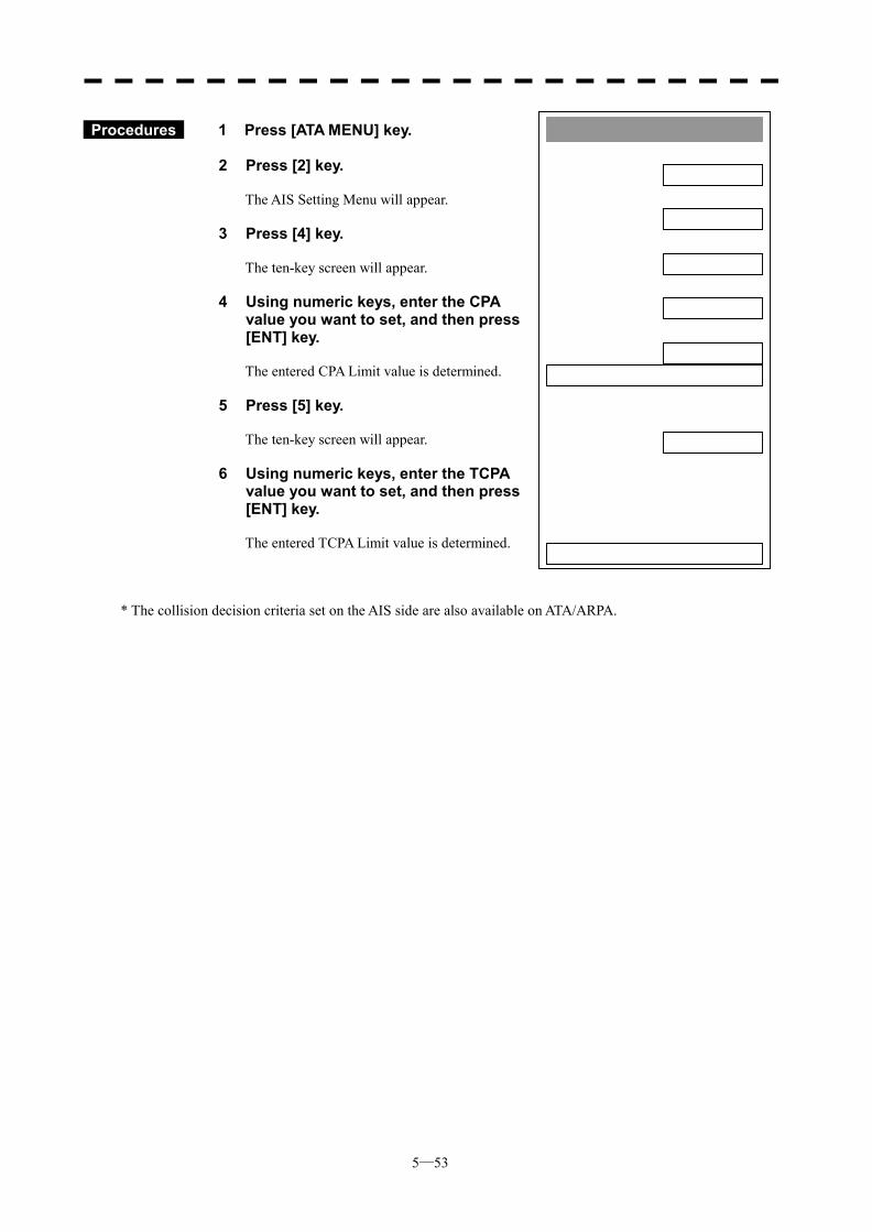
5─53
AIS Setting1. AIS Function
OFF2. AIS Symbol Display
OFF3. ATA Symbol Display
ON4. CPA Limit
1 nm5. TCPA Limit
1 min6. AIS Filter Setting >
7. Identical Distance100 m
0. EXIT
Procedures 1 Press [ATA MENU] key.
2 Press [2] key.
The AIS Setting Menu will appear.
3 Press [4] key. The ten-key screen will appear.
4 Using numeric keys, enter the CPA value you want to set, and then press [ENT] key. The entered CPA Limit value is determined.
5 Press [5] key. The ten-key screen will appear.
6 Using numeric keys, enter the TCPA value you want to set, and then press [ENT] key. The entered TCPA Limit value is determined.
* The collision decision criteria set on the AIS side are also available on ATA/ARPA.
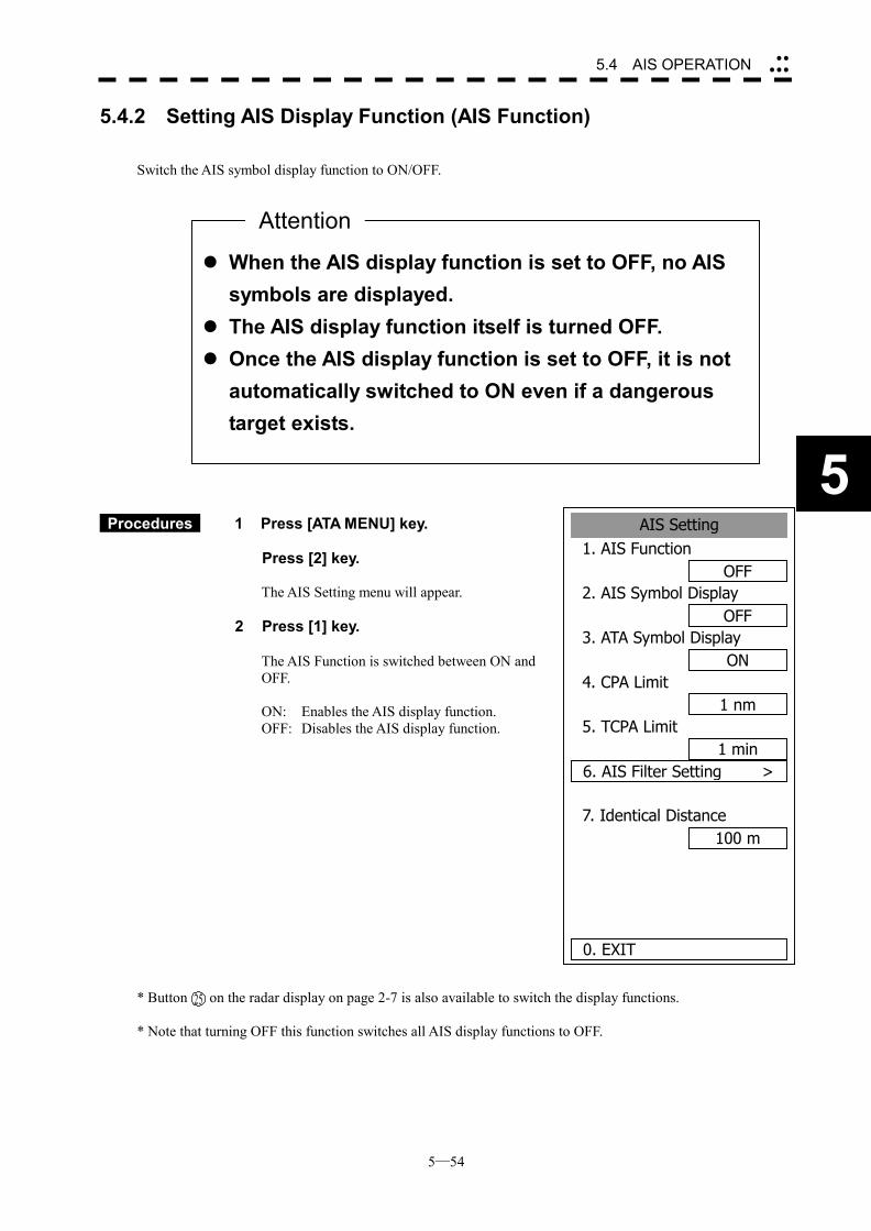
5─54
5.4 AIS OPERATION ��
���
5
5.4.2 Setting AIS Display Function (AIS Function) Switch the AIS symbol display function to ON/OFF.
Procedures 1 Press [ATA MENU] key.
Press [2] key.
The AIS Setting menu will appear.
2 Press [1] key.
The AIS Function is switched between ON and OFF.
ON: Enables the AIS display function. OFF: Disables the AIS display function.
* Button on the radar display on page 2-7 is also available to switch the display functions. * Note that turning OFF this function switches all AIS display functions to OFF.
��When the AIS display function is set to OFF, no AIS symbols are displayed.
��The AIS display function itself is turned OFF. ��Once the AIS display function is set to OFF, it is not
automatically switched to ON even if a dangerous target exists.
Attention
AIS Setting1. AIS Function
OFF2. AIS Symbol Display
OFF3. ATA Symbol Display
ON4. CPA Limit
1 nm5. TCPA Limit
1 min6. AIS Filter Setting >
7. Identical Distance100 m
0. EXIT
25
5─55
5.4.3 Activating AIS Targets Activate an AIS target, and display the target’s vector and make a collision decision.
Manual activation Activate an AIS target*1 in manual mode to display the vector and HL.
Procedures 1 Press the CURSOR button at the upper right of the radar display
several times until ACT AIS appears.
The cursor mode is set to the AIS activation mode.
2 Move the cross cursor mark onto the inactive AIS target that is to be
activated*1, and press [ENT] key.
The selected AIS target will be activated*1.
Automatic activation Activate an AIS target in automatic mode to display the vector and HL. If the guard zone function is in use, an AIS target is activated automatically when it has entered the guard zone. Dangerous targets are also activated automatically. The guard zone is the same as for ATA/ARPA. For the setting procedure, refer to “Setting Guard Zone” in 3.4 BASIC OPERATION of the instruction manual.
Reference If an AIS target is activated but the vector is not displayed, refer to Section 5.4.9 Setting AIS Symbol Display.
*1 For activation of targets, refer to Section 5.1.2 Definitions of Symbols.
5─56
5.4 AIS OPERATION ��
���
5
��The operation above is effective only for active targets.
5.4.4 Deactivating AIS Targets Deactivate an AIS target*2 and clear the display of the vector and HL.
Procedures 1 Press the CURSOR button at the upper right of the radar display
several times until CANCEL appears. The cursor mode is set to the deactivation mode.
2 Move the cross cursor mark onto the active AIS target that is to be
deactivated*2, and press [ENT] key. The selected AIS target will be deactivated*2 .
*2 For deactivation of targets, refer to Section 5.1.2 DEFINITIONS OF SYMBOLS.
Attention
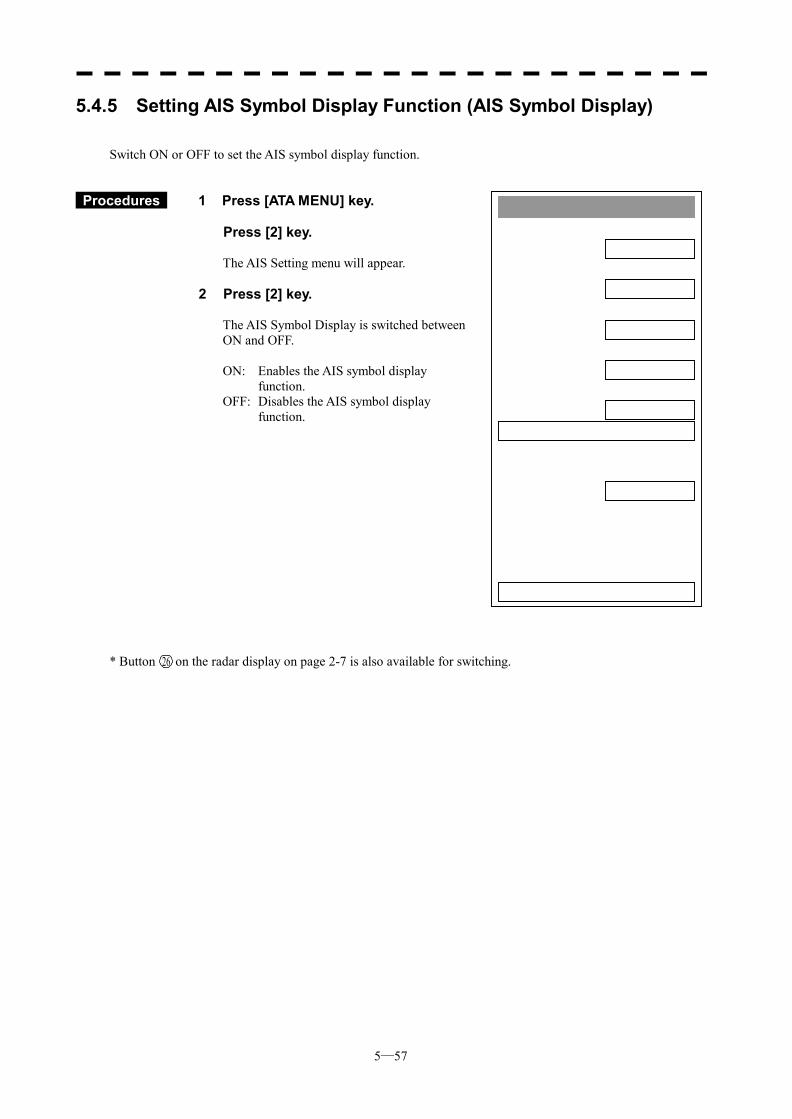
5─57
AIS Setting1. AIS Function
OFF2. AIS Symbol Display
OFF3. ATA Symbol Display
ON4. CPA Limit
1 nm5. TCPA Limit
1 min6. AIS Filter Setting >
7. Identical Distance100 m
0. EXIT
5.4.5 Setting AIS Symbol Display Function (AIS Symbol Display) Switch ON or OFF to set the AIS symbol display function.
Procedures 1 Press [ATA MENU] key.
Press [2] key.
The AIS Setting menu will appear.
2 Press [2] key.
The AIS Symbol Display is switched between ON and OFF.
ON: Enables the AIS symbol display
function. OFF: Disables the AIS symbol display
function. * Button on the radar display on page 2-7 is also available for switching.
26
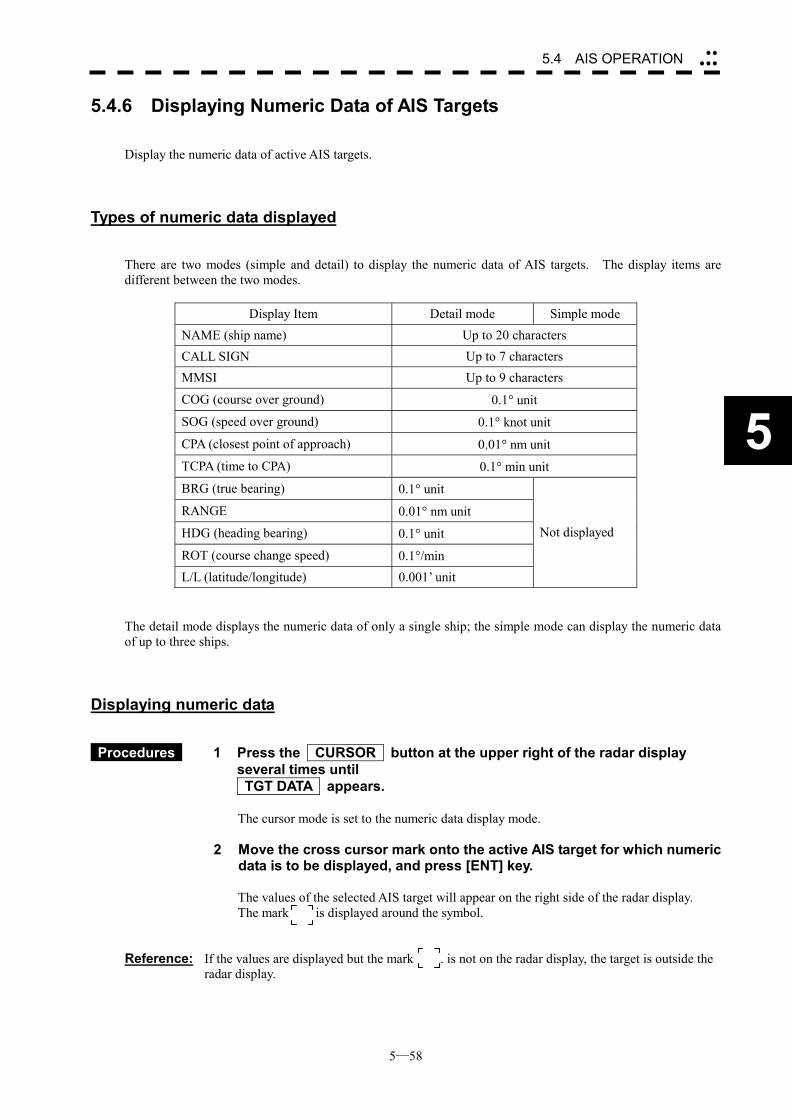
5─58
5.4 AIS OPERATION ��
���
5
5.4.6 Displaying Numeric Data of AIS Targets Display the numeric data of active AIS targets.
Types of numeric data displayed There are two modes (simple and detail) to display the numeric data of AIS targets. The display items are different between the two modes.
Display Item Detail mode Simple mode NAME (ship name) Up to 20 characters CALL SIGN Up to 7 characters MMSI Up to 9 characters
COG (course over ground) 0.1� unit SOG (speed over ground) 0.1� knot unit
CPA (closest point of approach) 0.01� nm unit TCPA (time to CPA) 0.1� min unit
BRG (true bearing) 0.1� unit
RANGE 0.01� nm unit HDG (heading bearing) 0.1� unit
ROT (course change speed) 0.1�/min L/L (latitude/longitude) 0.001’ unit
Not displayed
The detail mode displays the numeric data of only a single ship; the simple mode can display the numeric data of up to three ships.
Displaying numeric data
Procedures 1 Press the CURSOR button at the upper right of the radar display
several times until TGT DATA appears.
The cursor mode is set to the numeric data display mode.
2 Move the cross cursor mark onto the active AIS target for which numeric
data is to be displayed, and press [ENT] key.
The values of the selected AIS target will appear on the right side of the radar display. The mark is displayed around the symbol.
Reference: If the values are displayed but the mark . is not on the radar display, the target is outside the
radar display.
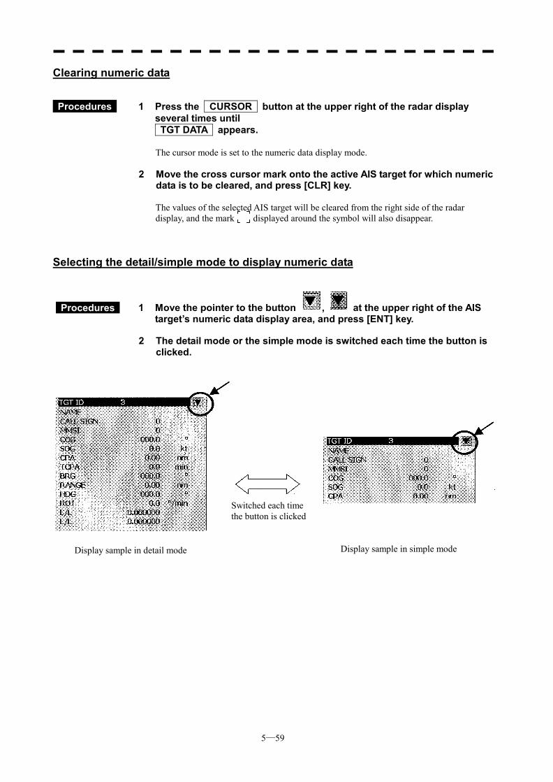
5─59
Clearing numeric data
Procedures 1 Press the CURSOR button at the upper right of the radar display
several times until TGT DATA appears.
The cursor mode is set to the numeric data display mode.
2 Move the cross cursor mark onto the active AIS target for which numeric
data is to be cleared, and press [CLR] key.
The values of the selected AIS target will be cleared from the right side of the radar display, and the mark displayed around the symbol will also disappear.
Selecting the detail/simple mode to display numeric data
1 Move the pointer to the button , at the upper right of the AIS target’s numeric data display area, and press [ENT] key.
2 The detail mode or the simple mode is switched each time the button is
clicked.
Switched each time the button is clicked
Display sample in detail mode Display sample in simple mode
Procedures
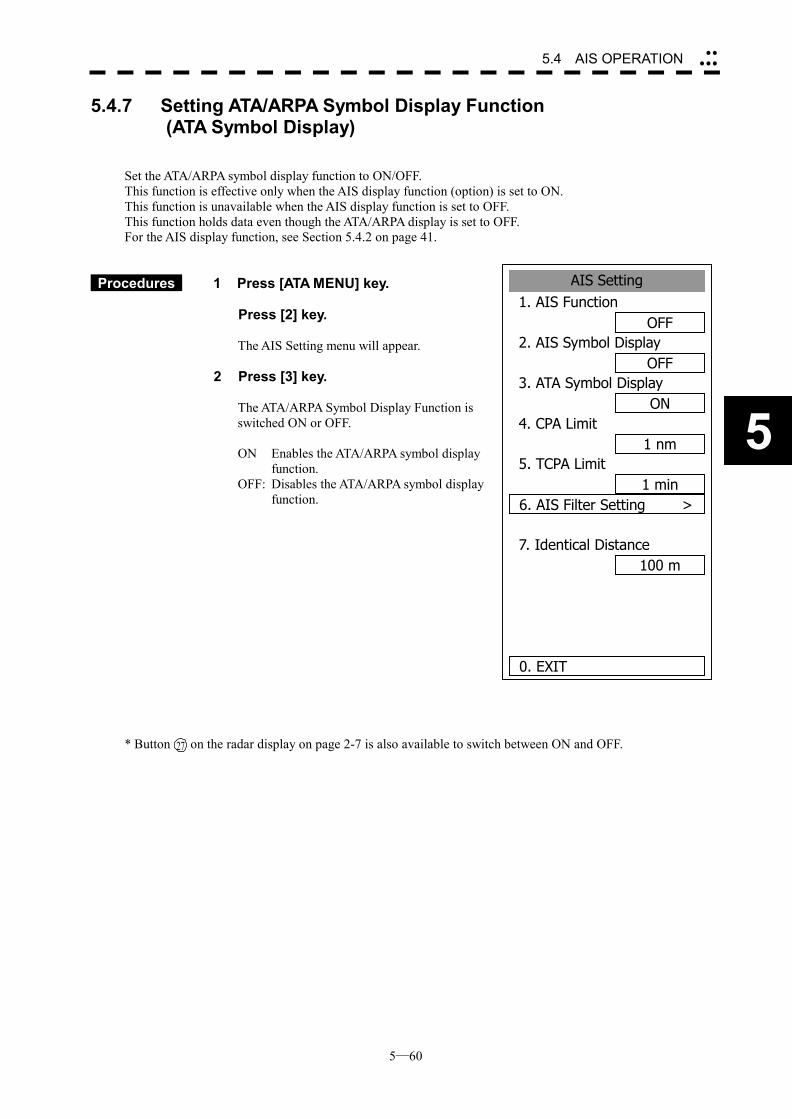
5─60
5.4 AIS OPERATION ��
���
5
5.4.7 Setting ATA/ARPA Symbol Display Function (ATA Symbol Display)
Set the ATA/ARPA symbol display function to ON/OFF. This function is effective only when the AIS display function (option) is set to ON. This function is unavailable when the AIS display function is set to OFF. This function holds data even though the ATA/ARPA display is set to OFF. For the AIS display function, see Section 5.4.2 on page 41.
Procedures 1 Press [ATA MENU] key.
Press [2] key.
The AIS Setting menu will appear.
2 Press [3] key.
The ATA/ARPA Symbol Display Function is switched ON or OFF. ON Enables the ATA/ARPA symbol display
function. OFF: Disables the ATA/ARPA symbol display
function. * Button on the radar display on page 2-7 is also available to switch between ON and OFF.
AIS Setting1. AIS Function
OFF2. AIS Symbol Display
OFF3. ATA Symbol Display
ON4. CPA Limit
1 nm5. TCPA Limit
1 min6. AIS Filter Setting >
7. Identical Distance100 m
0. EXIT
27
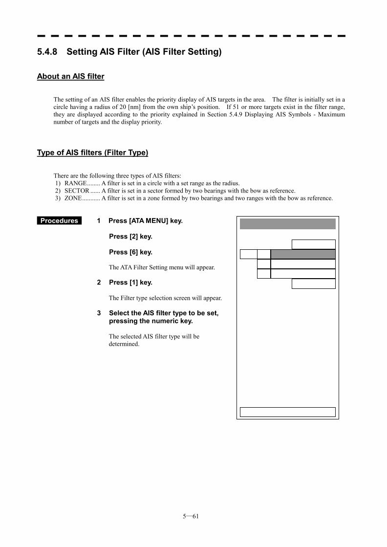
5─61
AIS Filter Setting1. Filter Type
RANGE2. Make AIS Filter
3. Filter DisplayON
0. EXIT
1. RANGE2. SECTOR3. ZONE
5.4.8 Setting AIS Filter (AIS Filter Setting)
About an AIS filter The setting of an AIS filter enables the priority display of AIS targets in the area. The filter is initially set in a circle having a radius of 20 [nm] from the own ship’s position. If 51 or more targets exist in the filter range, they are displayed according to the priority explained in Section 5.4.9 Displaying AIS Symbols - Maximum number of targets and the display priority.
Type of AIS filters (Filter Type) There are the following three types of AIS filters: 1) RANGE........ A filter is set in a circle with a set range as the radius. 2) SECTOR ...... A filter is set in a sector formed by two bearings with the bow as reference. 3) ZONE........... A filter is set in a zone formed by two bearings and two ranges with the bow as reference.
Procedures 1 Press [ATA MENU] key. Press [2] key. Press [6] key.
The ATA Filter Setting menu will appear.
2 Press [1] key.
The Filter type selection screen will appear.
3 Select the AIS filter type to be set, pressing the numeric key.
The selected AIS filter type will be determined.
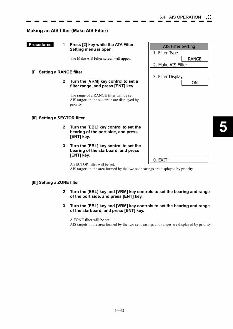
5─62
5.4 AIS OPERATION ��
���
5
Making an AIS filter (Make AIS Filter)
Procedures 1 Press [2] key while the ATA Filter
Setting menu is open. The Make AIS Filter screen will appear.
[I] Setting a RANGE filter
2 Turn the [VRM] key control to set a filter range, and press [ENT] key.
The range of a RANGE filter will be set. AIS targets in the set circle are displayed by priority.
[II] Setting a SECTOR filter
2 Turn the [EBL] key control to set the bearing of the port side, and press [ENT] key.
3 Turn the [EBL] key control to set the
bearing of the starboard, and press [ENT] key. A SECTOR filter will be set. AIS targets in the area formed by the two set bearings are displayed by priority.
[III] Setting a ZONE filter
2 Turn the [EBL] key and [VRM] key controls to set the bearing and range of the port side, and press [ENT] key.
3 Turn the [EBL] key and [VRM] key controls to set the bearing and range
of the starboard, and press [ENT] key.
A ZONE filter will be set. AIS targets in the area formed by the two set bearings and ranges are displayed by priority.
AIS Filter Setting1. Filter Type
RANGE2. Make AIS Filter
3. Filter DisplayON
0. EXIT
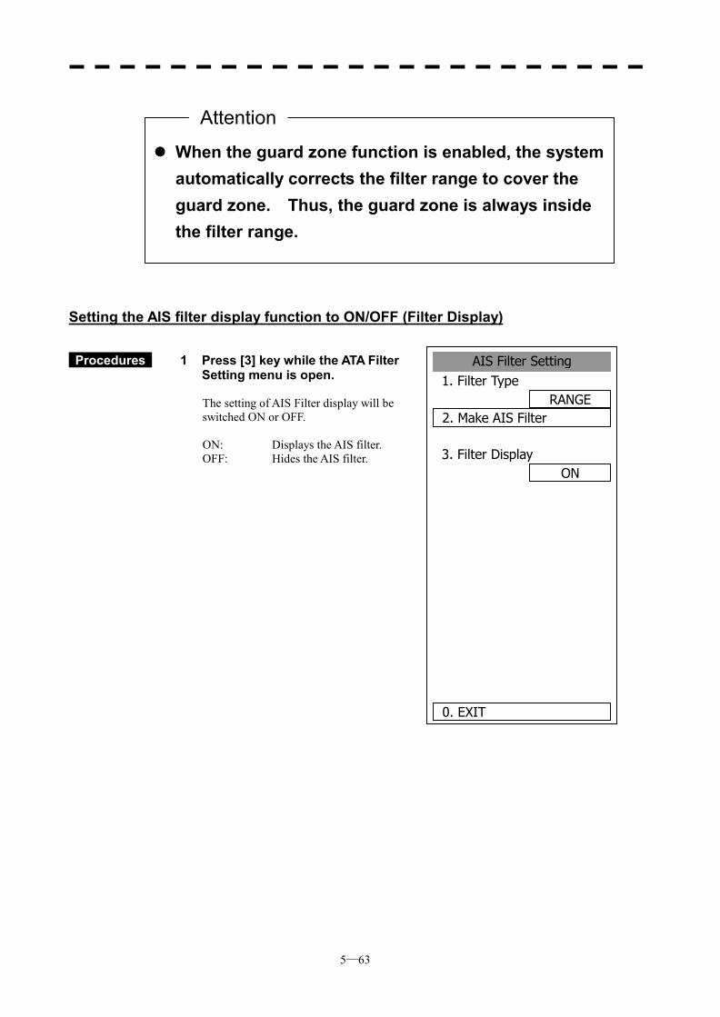
5─63
Setting the AIS filter display function to ON/OFF (Filter Display)
Procedures 1 Press [3] key while the ATA Filter
Setting menu is open. The setting of AIS Filter display will be switched ON or OFF.
ON: Displays the AIS filter. OFF: Hides the AIS filter.
��When the guard zone function is enabled, the system automatically corrects the filter range to cover the guard zone. Thus, the guard zone is always inside the filter range.
Attention
AIS Filter Setting1. Filter Type
RANGE2. Make AIS Filter
3. Filter DisplayON
0. EXIT
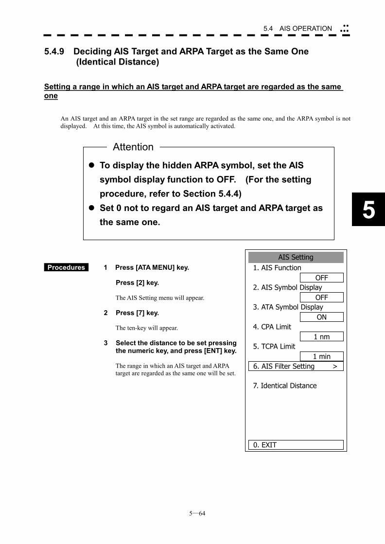
5─64
5.4 AIS OPERATION ��
���
5
5.4.9 Deciding AIS Target and ARPA Target as the Same One (Identical Distance)
Setting a range in which an AIS target and ARPA target are regarded as the same one
An AIS target and an ARPA target in the set range are regarded as the same one, and the ARPA symbol is not displayed. At this time, the AIS symbol is automatically activated.
Procedures 1 Press [ATA MENU] key.
Press [2] key.
The AIS Setting menu will appear.
2 Press [7] key.
The ten-key will appear.
3 Select the distance to be set pressing
the numeric key, and press [ENT] key. The range in which an AIS target and ARPA target are regarded as the same one will be set.
��To display the hidden ARPA symbol, set the AIS symbol display function to OFF. (For the setting procedure, refer to Section 5.4.4)
��Set 0 not to regard an AIS target and ARPA target as the same one.
Attention
AIS Setting1. AIS Function
OFF2. AIS Symbol Display
OFF3. ATA Symbol Display
ON4. CPA Limit
1 nm5. TCPA Limit
1 min6. AIS Filter Setting >
7. Identical Distance
0. EXIT
5─65
CAUTION
When setting large values in determining the distance to the same target, the ARPA target near the AIS target may be not displayed. For example, when a pilot ship with AIS function, which is a small target, not ARPA target, approaches to a cargo ship without ARPA function, which is an ARPA target, the cargo ship’s ARPA symbol may not be displayed.
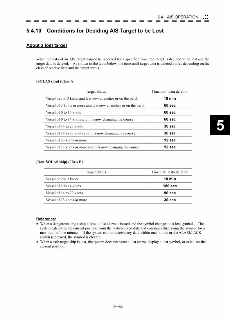
5─66
5.4 AIS OPERATION ��
���
5
5.4.10 Conditions for Deciding AIS Target to be Lost
About a lost target When the data of an AIS target cannot be received for a specified time, the target is decided to be lost and the target data is deleted. As shown in the table below, the time until target data is deleted varies depending on the class of receive data and the target status. [SOLAS ship] (Class A)
Target Status Time until data deletion
Vessel below 3 knots and it is now at anchor or on the berth 18 min
Vessel of 3 knots or more and it is now at anchor or on the berth 60 sec
Vessel of 0 to 14 knots 60 sec
Vessel of 0 to 14 knots and it is now changing the course 60 sec
Vessel of 14 to 23 knots 36 sec
Vessel of 14 to 23 knots and it is now changing the course 36 sec
Vessel of 23 knots or more 12 sec
Vessel of 23 knots or more and it is now changing the course 12 sec [Non-SOLAS ship] (Class B)
Target Status Time until data deletion
Vessel below 2 knots 18 min
Vessel of 2 to 14 knots 180 sec
Vessel of 14 to 23 knots 90 sec
Vessel of 23 knots or more 30 sec Reference: � When a dangerous target ship is lost, a lost alarm is issued and the symbol changes to a lost symbol. The
system calculates the current position from the last-received data and continues displaying the symbol for a maximum of one minute. If the system cannot receive any data within one minute or the ALARM ACK switch is pressed, the symbol is cleared.
� When a safe target ship is lost, the system does not issue a lost alarm, display a lost symbol, or calculate the current position.
5─67
��If a vector is not displayed even when the AIS symbol is activated, probable causes are as follows: 1. COG/SOG from the GPS has not been entered. 2. The selected speed sensor is malfunctioning.
5.4.11 Displaying AIS Symbols
Maximum number of targets and the display priority A radar of the JMA-5300 series displays AIS symbols for a maximum of 50 targets. When 51 AIS targets or more exist, they are displayed according to the following priority:
1. Target for which numeric data is displayed 2. Target displayed by the AIS target search function 3. arget in the AIS filter (Targets closer to the own ship in the filter have higher priority.) 4. Target whose CPA/TCPA is the set value or less. (Target for which a dangerous ship alarm has been issued) 5. Targets other than the above, which are outside the AIS filter
(Targets closer to the own ship in the filter have higher priority.)
Displaying the vectors of AIS symbols The vector of an AIS symbol is to be displayed as a vector over water or over ground, depending on the speed sensor setting and current offset setting. The type of the currently displayed vector is confirmed in the own ship’s information display area at the upper right of the radar display. When “GND” is displayed to the right of OS STAB: Vector over ground When “SEA” is displayed to the right of OS STAB: Vector over water When the vector of an AIS symbol is displayed as a vector over water, the system has converted the AIS symbol’s vector over ground to the vector over water according to the data received from the AIS and the own ship’s information.
��When the system receives the data of the 51-th target ship, it displays AIS MAX TARGET at the right lower of the radar display, and issues audible alarm (beep sound of pipi).
Attention
Attention
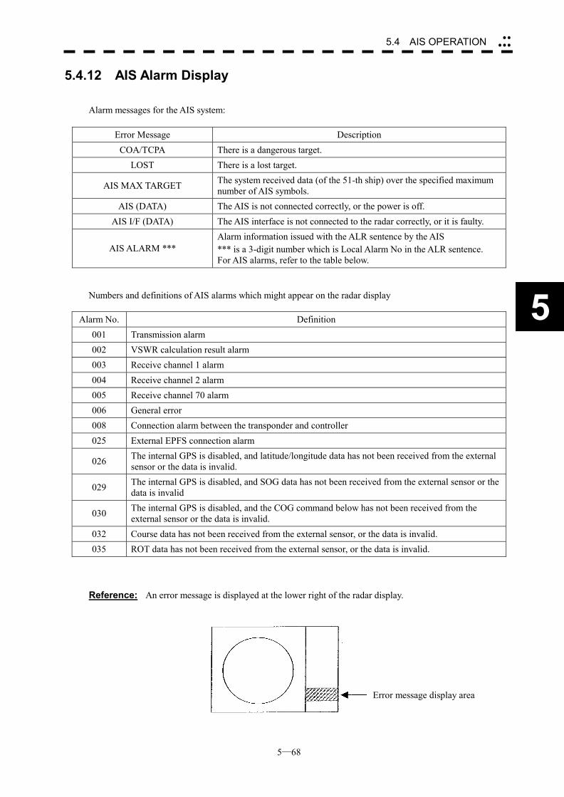
5─68
5.4 AIS OPERATION ��
���
5
5.4.12 AIS Alarm Display Alarm messages for the AIS system:
Error Message Description
COA/TCPA There is a dangerous target. LOST There is a lost target.
AIS MAX TARGET The system received data (of the 51-th ship) over the specified maximum number of AIS symbols.
AIS (DATA) The AIS is not connected correctly, or the power is off. AIS I/F (DATA) The AIS interface is not connected to the radar correctly, or it is faulty.
AIS ALARM *** Alarm information issued with the ALR sentence by the AIS *** is a 3-digit number which is Local Alarm No in the ALR sentence. For AIS alarms, refer to the table below.
Numbers and definitions of AIS alarms which might appear on the radar display
Alarm No. Definition 001 Transmission alarm 002 VSWR calculation result alarm 003 Receive channel 1 alarm 004 Receive channel 2 alarm 005 Receive channel 70 alarm 006 General error 008 Connection alarm between the transponder and controller 025 External EPFS connection alarm
026 The internal GPS is disabled, and latitude/longitude data has not been received from the external sensor or the data is invalid.
029 The internal GPS is disabled, and SOG data has not been received from the external sensor or the data is invalid
030 The internal GPS is disabled, and the COG command below has not been received from the external sensor or the data is invalid.
032 Course data has not been received from the external sensor, or the data is invalid. 035 ROT data has not been received from the external sensor, or the data is invalid.
Reference: An error message is displayed at the lower right of the radar display.
Error message display area
5─69
5.4.13 Restrictions The following restrictions are placed on use of the AIS function: The AIS function is unavailable in the following cases: �� “MANUAL” is selected for the speed sensor. �� SET or DRIFT is set while LOG or 2AXW is selected for the speed sensor. LOG or 2AXW cannot be selected for the speed sensor in the following case: �� SET or DRIFT is set while the AIS function is on. MANUAL cannot be selected for the speed sensor in the following case: ��The AIS function is on. Current offset (SET/DRIFT) cannot be turned on in the following case: ��LOG or 2AXW is selected for the speed sensor while the AIS function is on.
SECTION 6 TRUE AND FALSE ECHOES
ON DISPLAY
6.1 Radar Wave with the Horizon....................6-2 6.2 Strength of Reflection from the Targets ..6-4 6.3 Sea Clutters ................................................6-5 6.4 False Echoes ..............................................6-6 6.5 Display of Radar Transponder (SART).....6-9

6─1
The radar operator has a role of interpreting the radar displays to provide his best aid in maneuvering the ship. For this purpose, the operator has to observe the radar displays after fully understanding the advantages and disadvantages that the radar has. For better interpretation of radar display, it is important to gain more experiences by operating the radar equipment in fair weathers and comparing the target ships watched with the naked eyes and their echoes on the radar display. The radar is mainly used to monitor the courses of own ship and other ships in open seas, to check buoys and other nautical marks when entering a port, to measure own ship’s position in the coastal waters relative to the bearings and ranges of the shore or islands using a chart, and to monitor the position and movement of a heavy rain if it appears on the radar display. Various types of radar display will be explained below.
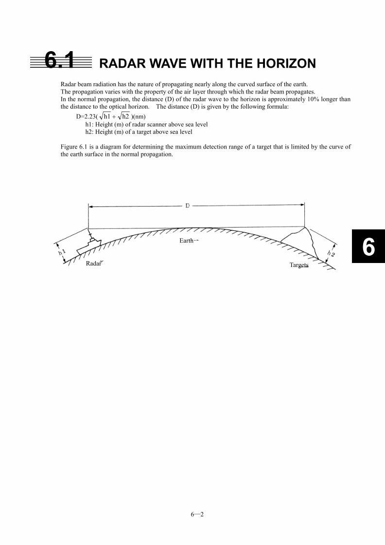
6─2
6
6.1 RADAR WAVE WITH THE HORIZON Radar beam radiation has the nature of propagating nearly along the curved surface of the earth. The propagation varies with the property of the air layer through which the radar beam propagates. In the normal propagation, the distance (D) of the radar wave to the horizon is approximately 10% longer than the distance to the optical horizon. The distance (D) is given by the following formula:
D=2.23( h2h1 � )(nm) h1: Height (m) of radar scanner above sea level h2: Height (m) of a target above sea level
Figure 6.1 is a diagram for determining the maximum detection range of a target that is limited by the curve of the earth surface in the normal propagation.
Radar
Earth
Targets
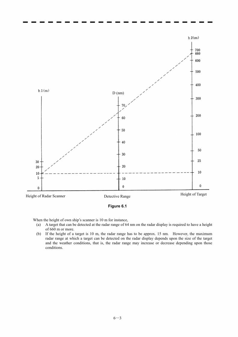
6─3
Figure 6.1
When the height of own ship’s scanner is 10 m for instance, (a) A target that can be detected at the radar range of 64 nm on the radar display is required to have a height
of 660 m or more. (b) If the height of a target is 10 m, the radar range has to be approx. 15 nm. However, the maximum
radar range at which a target can be detected on the radar display depends upon the size of the target and the weather conditions, that is, the radar range may increase or decrease depending upon those conditions.
Height of Radar Scanner Detective Range Height of Target
D (nm)
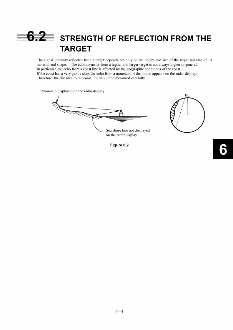
6─4
6
6.2 STRENGTH OF REFLECTION FROM THE TARGET
The signal intensity reflected from a target depends not only on the height and size of the target but also on its material and shape. The echo intensity from a higher and larger target is not always higher in general. In particular, the echo from a coast line is affected by the geographic conditions of the coast. If the coast has a very gentle slop, the echo from a mountain of the inland appears on the radar display. Therefore, the distance to the coast line should be measured carefully.
Figure 6.2
Mountain displayed on the radar display
Sea shore line not displayed on the radar display.
6─5
6.3 SEA CLUTTERS When the sea surface ruffles, bright echo returns spread around the center of the radar display. The higher the waves are, the echo returns are larger. Swirling currents may appear as a smooth line like a coastal line.
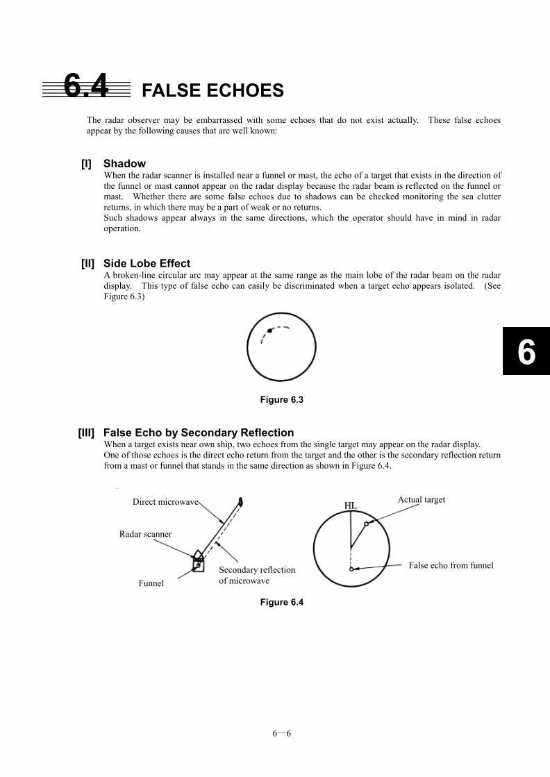
6─6
6
6.4 FALSE ECHOES The radar observer may be embarrassed with some echoes that do not exist actually. These false echoes appear by the following causes that are well known:
[I] Shadow When the radar scanner is installed near a funnel or mast, the echo of a target that exists in the direction of the funnel or mast cannot appear on the radar display because the radar beam is reflected on the funnel or mast. Whether there are some false echoes due to shadows can be checked monitoring the sea clutter returns, in which there may be a part of weak or no returns. Such shadows appear always in the same directions, which the operator should have in mind in radar operation.
[II] Side Lobe Effect
A broken-line circular arc may appear at the same range as the main lobe of the radar beam on the radar display. This type of false echo can easily be discriminated when a target echo appears isolated. (See Figure 6.3)
Figure 6.3
[III] False Echo by Secondary Reflection When a target exists near own ship, two echoes from the single target may appear on the radar display. One of those echoes is the direct echo return from the target and the other is the secondary reflection return from a mast or funnel that stands in the same direction as shown in Figure 6.4.
Figure 6.4
Direct microwave
Radar scanner
Funnel
Actual target
Secondary reflection of microwave
False echo from funnel
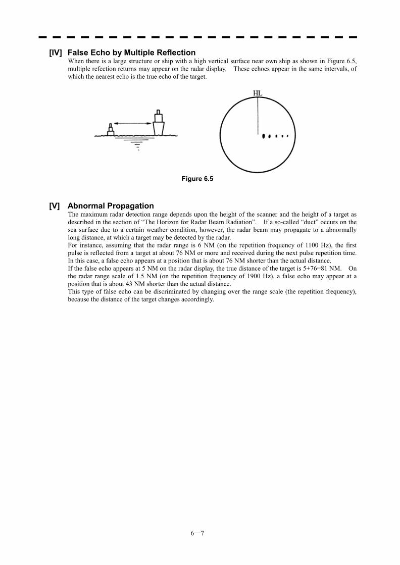
6─7
[IV] False Echo by Multiple Reflection When there is a large structure or ship with a high vertical surface near own ship as shown in Figure 6.5, multiple refection returns may appear on the radar display. These echoes appear in the same intervals, of which the nearest echo is the true echo of the target.
Figure 6.5
[V] Abnormal Propagation
The maximum radar detection range depends upon the height of the scanner and the height of a target as described in the section of “The Horizon for Radar Beam Radiation”. If a so-called “duct” occurs on the sea surface due to a certain weather condition, however, the radar beam may propagate to a abnormally long distance, at which a target may be detected by the radar. For instance, assuming that the radar range is 6 NM (on the repetition frequency of 1100 Hz), the first pulse is reflected from a target at about 76 NM or more and received during the next pulse repetition time. In this case, a false echo appears at a position that is about 76 NM shorter than the actual distance. If the false echo appears at 5 NM on the radar display, the true distance of the target is 5+76=81 NM. On the radar range scale of 1.5 NM (on the repetition frequency of 1900 Hz), a false echo may appear at a position that is about 43 NM shorter than the actual distance. This type of false echo can be discriminated by changing over the range scale (the repetition frequency), because the distance of the target changes accordingly.
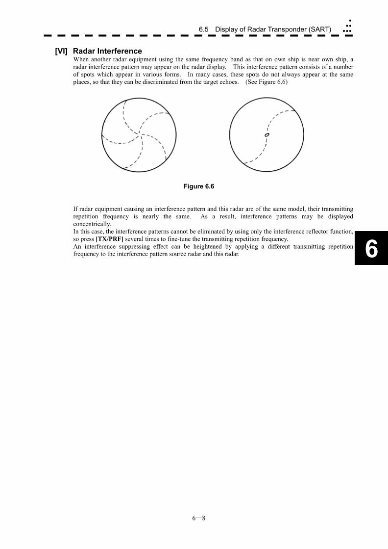
6─8
6.5 Display of Radar Transponder (SART)�
��
���
6
[VI] Radar Interference When another radar equipment using the same frequency band as that on own ship is near own ship, a radar interference pattern may appear on the radar display. This interference pattern consists of a number of spots which appear in various forms. In many cases, these spots do not always appear at the same places, so that they can be discriminated from the target echoes. (See Figure 6.6)
Figure 6.6
If radar equipment causing an interference pattern and this radar are of the same model, their transmitting repetition frequency is nearly the same. As a result, interference patterns may be displayed concentrically. In this case, the interference patterns cannot be eliminated by using only the interference reflector function, so press [TX/PRF] several times to fine-tune the transmitting repetition frequency. An interference suppressing effect can be heightened by applying a different transmitting repetition frequency to the interference pattern source radar and this radar.

6─9
6.5 DISPLAY OF RADAR TRANSPONDER (SART)
The SART (Search and rescue Radar Transponder) is a survival device authorized by the GMDSS (Global Maritime Distress and Safety System), which is used for locating survivors in case that a distress accident occurs at sea. The SART is designed to operate in the 9 GHz frequency band. When receiving the 9 GHz radar signal (interrogating signal) transmitted from the radar equipment on a rescue ship or search aircraft, the SART transmit a series of response signals to inform the distress position to the rescue and search party. * This radar provides a shortcut item to make settings for SART signal reception. Execution of this item
automatically switches to the setting for SART reception.
Procedures 1 Press [RANGE +] or [RANGE -] to
set the radar range to 6 NM or 12 NM.
2 Press [RADAR MENU].
The Main Menu will appear.
3 Press [5].
Each time the key is pressed, switching between ON and OFF takes place.
MAIN MENU1. IR
IR OFF2. Process
PROC OFF3. Target Enhance
OFF4. Zoom
OFF5. SART
ON6. NAV Information >
8. Graphic DisplayON
9. RADAR MENU(→ Plot)
0. EXIT
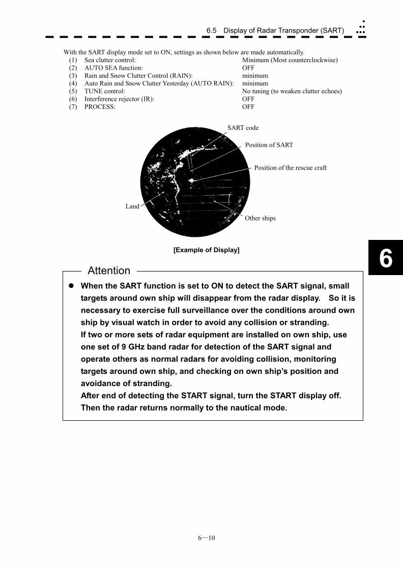
6─10
6.5 Display of Radar Transponder (SART)�
��
���
6
With the SART display mode set to ON, settings as shown below are made automatically. (1) Sea clutter control: Minimum (Most counterclockwise) (2) AUTO SEA function: OFF (3) Rain and Snow Clutter Control (RAIN): minimum (4) Auto Rain and Snow Clutter Yesterday (AUTO RAIN): minimum (5) TUNE control: No tuning (to weaken clutter echoes) (6) Interference rejector (IR): OFF (7) PROCESS: OFF
[Example of Display]
SART code
Position of SART
Position of the rescue craft
Other ships
Land
��When the SART function is set to ON to detect the SART signal, small targets around own ship will disappear from the radar display. So it is necessary to exercise full surveillance over the conditions around own ship by visual watch in order to avoid any collision or stranding. If two or more sets of radar equipment are installed on own ship, use one set of 9 GHz band radar for detection of the SART signal and operate others as normal radars for avoiding collision, monitoring targets around own ship, and checking on own ship’s position and avoidance of stranding. After end of detecting the START signal, turn the START display off. Then the radar returns normally to the nautical mode.
Attention
SECTION 7 MAINTEMANCE
7.1 Routine Maintenance .................................... 7-1 7.2 Maintenance on Each Unit ........................... 7-2
Scanner Unit NKE-2102/2252/1075 .............. 7-2 Display Unit NCD-4510 ................................. 7-8

7─1
7.1 ROUTINE MAINTENANCE
WARNING
Never carry out internal inspection or repair work of the equipment by users.
Inspection or repair work by unauthorized personnel may result in fire hazard or electric shock.
Ask the nearest branch, business office or a dealer for inspection and repair.
Turn off the main power before maintenance work. Otherwise, an electric shock may result.
Turn off the main power before cleaning the equipment. Especially, make sure to turn off the indicator if a rectifier is used. Otherwise, equipment failure, or death or serious injury due to electric shock may result, because voltage is outputted from the rectifier even when the radar is not operating.
For operating the radar equipment in the good conditions, it is necessary to make the maintenance work as described below. If maintenance is made properly, troubles will reduce. It is recommended to make regular maintenance work. Common points of maintenance for each unit are as follow: Clean the equipment. Remove the dust, dirt, and sea water rest on the equipment cabinet with a piece of dry cloth. Especially, clean the air vents with a brush for good ventilation.
7─2
7
7.2 MAINTENANCE ON EACH UNIT
Scanner Unit NKE-2102/2252/1075
WARNING
Turn off the main power source before starting maintenance. Otherwise, an electric shock or injury may be caused.
Turn off the main power if you need to be near the scanner unit for maintenance or inspection purposes. Direct exposure to electromagnetic waves at close range in death or serious injury.
Set the safety switch for stopping the scanner unit to the OFF position.
Otherwise, an accidental contact with the rotating scanner unit may cause injury.
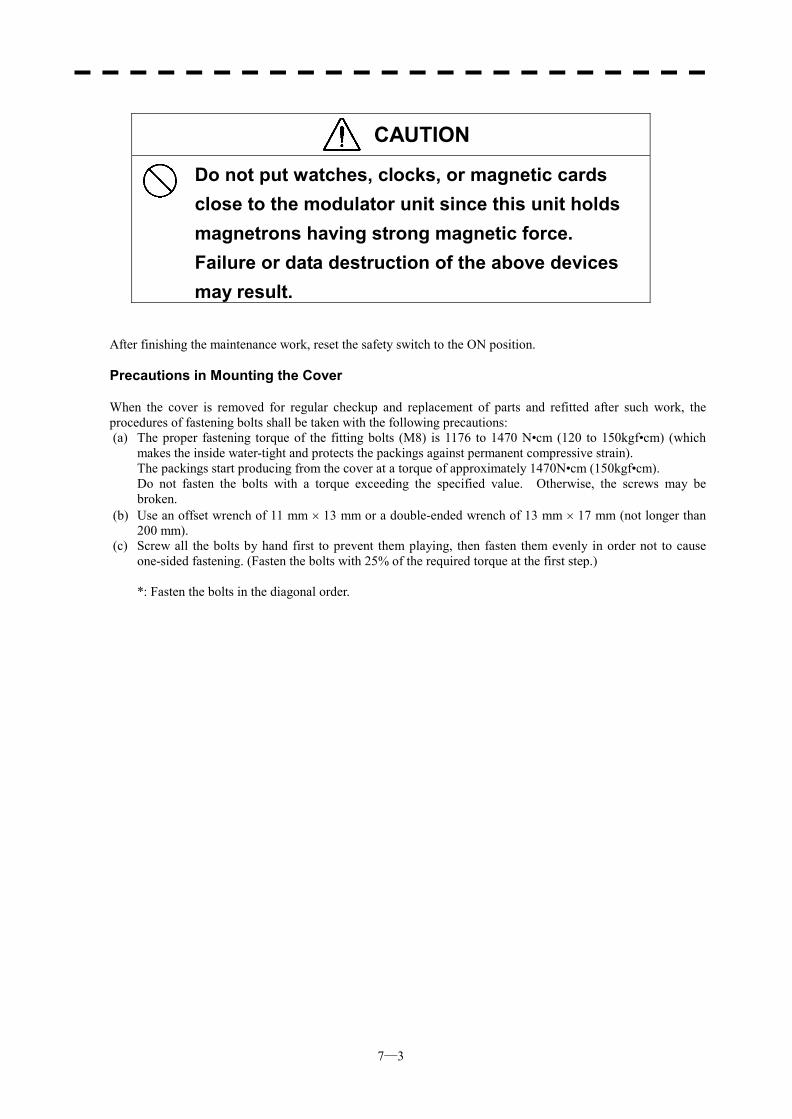
7─3
CAUTION
Do not put watches, clocks, or magnetic cards close to the modulator unit since this unit holds magnetrons having strong magnetic force. Failure or data destruction of the above devices may result.
After finishing the maintenance work, reset the safety switch to the ON position. Precautions in Mounting the Cover When the cover is removed for regular checkup and replacement of parts and refitted after such work, the procedures of fastening bolts shall be taken with the following precautions: (a) The proper fastening torque of the fitting bolts (M8) is 1176 to 1470 N•cm (120 to 150kgf•cm) (which
makes the inside water-tight and protects the packings against permanent compressive strain). The packings start producing from the cover at a torque of approximately 1470N•cm (150kgf•cm). Do not fasten the bolts with a torque exceeding the specified value. Otherwise, the screws may be
broken. (b) Use an offset wrench of 11 mm � 13 mm or a double-ended wrench of 13 mm � 17 mm (not longer than
200 mm). (c) Screw all the bolts by hand first to prevent them playing, then fasten them evenly in order not to cause
one-sided fastening. (Fasten the bolts with 25% of the required torque at the first step.) *: Fasten the bolts in the diagonal order.
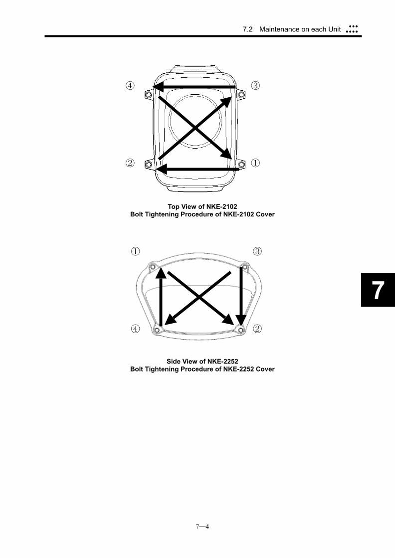
7─4
7.2 Maintenance on each Unit ���
����
7
Top View of NKE-2102 Bolt Tightening Procedure of NKE-2102 Cover
Side View of NKE-2252 Bolt Tightening Procedure of NKE-2252 Cover
④ ③
② ①
① ③
④ ②
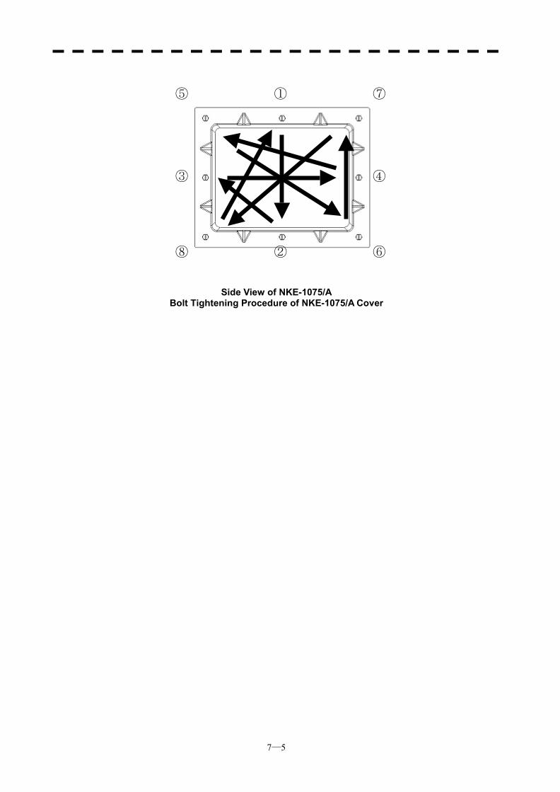
7─5
Side View of NKE-1075/A Bolt Tightening Procedure of NKE-1075/A Cover
①
③ ④
②
⑤
⑥
⑦
⑧
7─6
7.2 Maintenance on each Unit ���
����
7
(1) Radiator
Check up and clean the radiator.
��If the radiator front face (radiation plane) is soiled with smoke, salt, dust, paint or birds’ droppings, wipe it with a piece of soft cloth wetted with alcohol or water and try to keep it clean at all times. Otherwise, radar beam radiation may attenuate or reflect on it, resulting in deterioration of radar performance.
��Never use solvents of gasoline, benzine, trichloroethylene and ketone for cleaning. Otherwise, the radiation plane may deteriorate.
Attention
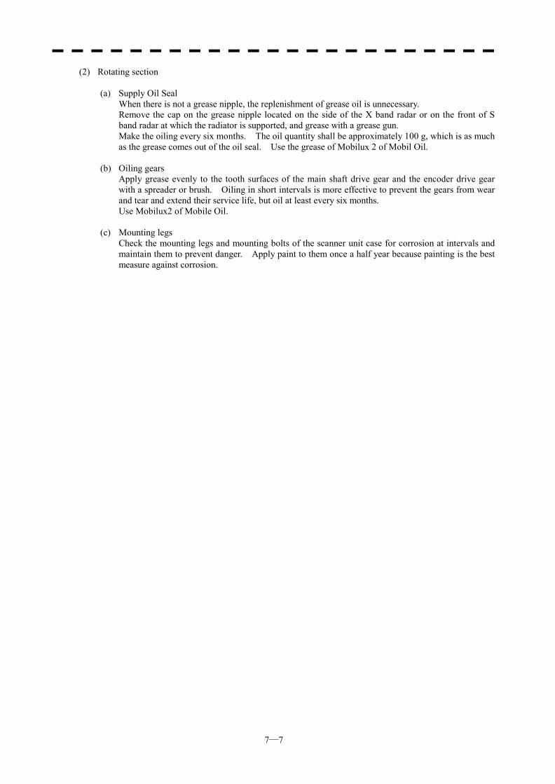
7─7
(2) Rotating section
(a) Supply Oil Seal When there is not a grease nipple, the replenishment of grease oil is unnecessary. Remove the cap on the grease nipple located on the side of the X band radar or on the front of S
band radar at which the radiator is supported, and grease with a grease gun. Make the oiling every six months. The oil quantity shall be approximately 100 g, which is as much
as the grease comes out of the oil seal. Use the grease of Mobilux 2 of Mobil Oil. (b) Oiling gears Apply grease evenly to the tooth surfaces of the main shaft drive gear and the encoder drive gear
with a spreader or brush. Oiling in short intervals is more effective to prevent the gears from wear and tear and extend their service life, but oil at least every six months.
Use Mobilux2 of Mobile Oil. (c) Mounting legs Check the mounting legs and mounting bolts of the scanner unit case for corrosion at intervals and
maintain them to prevent danger. Apply paint to them once a half year because painting is the best measure against corrosion.
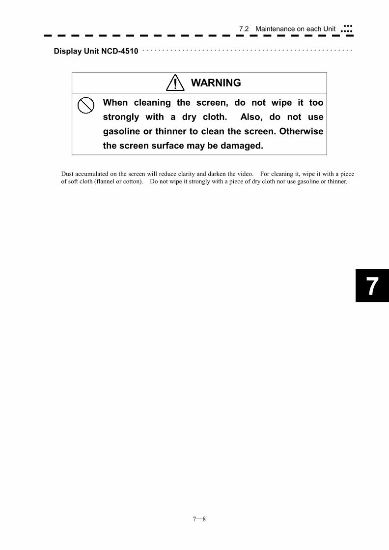
7─8
7.2 Maintenance on each Unit ���
����
7
Display Unit NCD-4510 ・・・・・・・・・・・・・・・・・・・・・・・・・・・・・・・・・・・・・・・・・・・・・・・・・・・・・
WARNING
When cleaning the screen, do not wipe it too strongly with a dry cloth. Also, do not use gasoline or thinner to clean the screen. Otherwise the screen surface may be damaged.
Dust accumulated on the screen will reduce clarity and darken the video. For cleaning it, wipe it with a piece of soft cloth (flannel or cotton). Do not wipe it strongly with a piece of dry cloth nor use gasoline or thinner.

SECTION 8 TROUBLE SHOOTING
AND ADJUSTMENT
8.1 Performance Check..........................8-1 8.2 Fault Finding...................................8-21 8.3 Trouble Shooting............................8-22 8.4 Replacement of Major Parts ..........8-27 8.5 Adjustments....................................8-30 8.6 Setting .............................................8-62
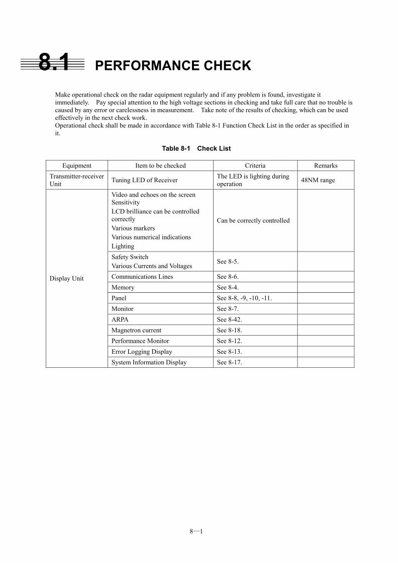
8─1
8.1 PERFORMANCE CHECK Make operational check on the radar equipment regularly and if any problem is found, investigate it immediately. Pay special attention to the high voltage sections in checking and take full care that no trouble is caused by any error or carelessness in measurement. Take note of the results of checking, which can be used effectively in the next check work. Operational check shall be made in accordance with Table 8-1 Function Check List in the order as specified in it.
Table 8-1 Check List
Equipment Item to be checked Criteria Remarks Transmitter-receiver Unit Tuning LED of Receiver The LED is lighting during
operation 48NM range
Video and echoes on the screen Sensitivity LCD brilliance can be controlled correctly Various markers Various numerical indications Lighting
Can be correctly controlled
Safety Switch Various Currents and Voltages
See 8-5.
Communications Lines See 8-6. Memory See 8-4. Panel See 8-8, -9, -10, -11. Monitor See 8-7. ARPA See 8-42. Magnetron current See 8-18. Performance Monitor See 8-12. Error Logging Display See 8-13.
Display Unit
System Information Display See 8-17.
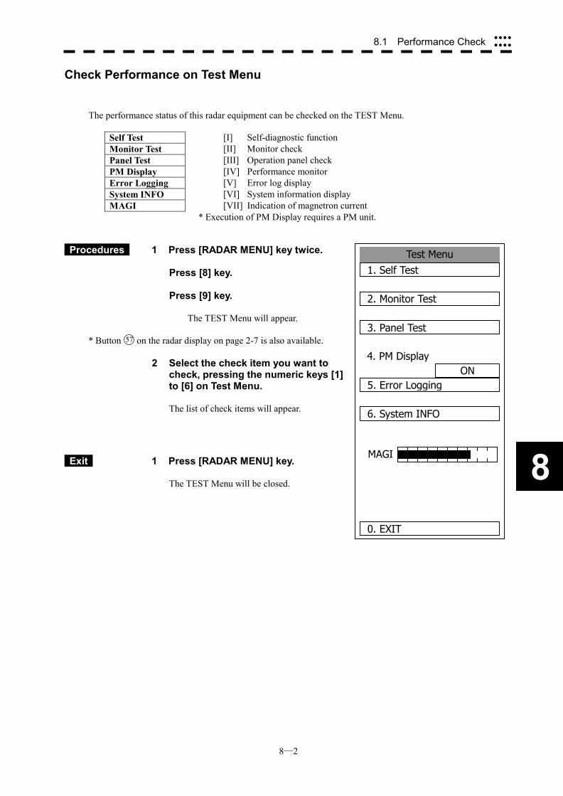
8─2
8
8.1 Performance Check ����
����
Test Menu1. Self Test
2. Monitor Test
3. Panel Test
4. PM DisplayON
5. Error Logging
6. System INFO
0. EXIT
MAGI
Check Performance on Test Menu
The performance status of this radar equipment can be checked on the TEST Menu.
Self Test [I] Self-diagnostic function Monitor Test [II] Monitor check Panel Test [III] Operation panel check PM Display [IV] Performance monitor Error Logging [V] Error log display System INFO [VI] System information display MAGI
[VII] Indication of magnetron current * Execution of PM Display requires a PM unit.
Procedures 1 Press [RADAR MENU] key twice. Press [8] key. Press [9] key.
The TEST Menu will appear.
* Button 57 on the radar display on page 2-7 is also available.
2 Select the check item you want to check, pressing the numeric keys [1] to [6] on Test Menu.
The list of check items will appear.
Exit 1 Press [RADAR MENU] key.
The TEST Menu will be closed.
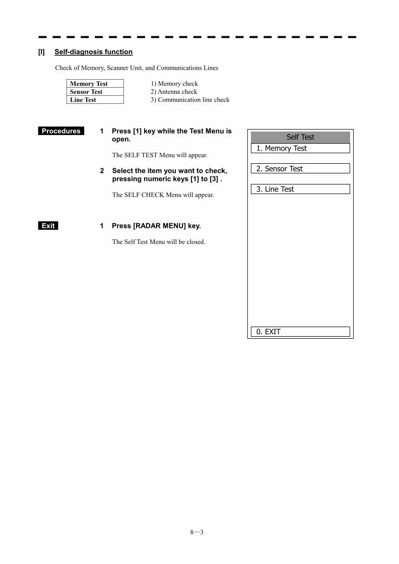
8─3
Self Test1. Memory Test
2. Sensor Test
3. Line Test
0. EXIT
[I] Self-diagnosis function
Check of Memory, Scanner Unit, and Communications Lines
Memory Test 1) Memory check Sensor Test 2) Antenna check Line Test
3) Communication line check
Procedures 1 Press [1] key while the Test Menu is open.
The SELF TEST Menu will appear.
2 Select the item you want to check, pressing numeric keys [1] to [3] .
The SELF CHECK Menu will appear.
Exit 1 Press [RADAR MENU] key.
The Self Test Menu will be closed.
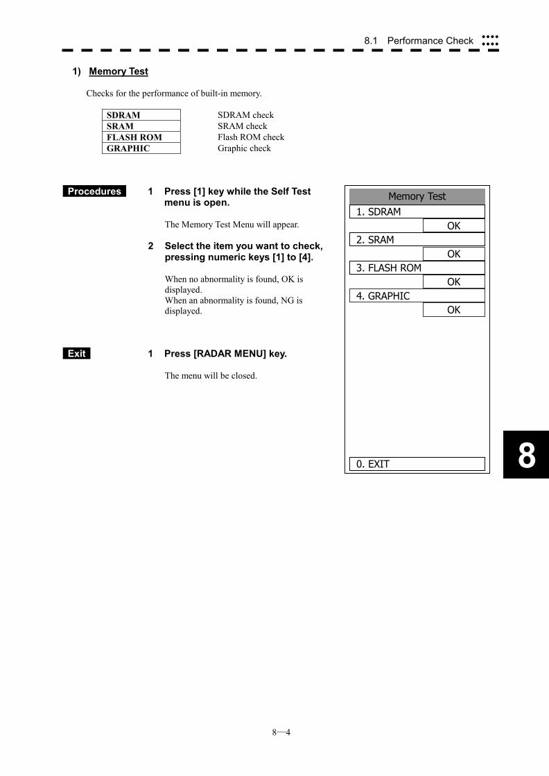
8─4
8
8.1 Performance Check ����
����
Memory Test1. SDRAM
OK2. SRAM
OK3. FLASH ROM
OK4. GRAPHIC
OK
0. EXIT
1) Memory Test
Checks for the performance of built-in memory.
SDRAM SDRAM check SRAM SRAM check FLASH ROM Flash ROM check GRAPHIC
Graphic check
Procedures 1 Press [1] key while the Self Test menu is open.
The Memory Test Menu will appear.
2 Select the item you want to check, pressing numeric keys [1] to [4].
When no abnormality is found, OK is displayed. When an abnormality is found, NG is displayed.
Exit 1 Press [RADAR MENU] key.
The menu will be closed.
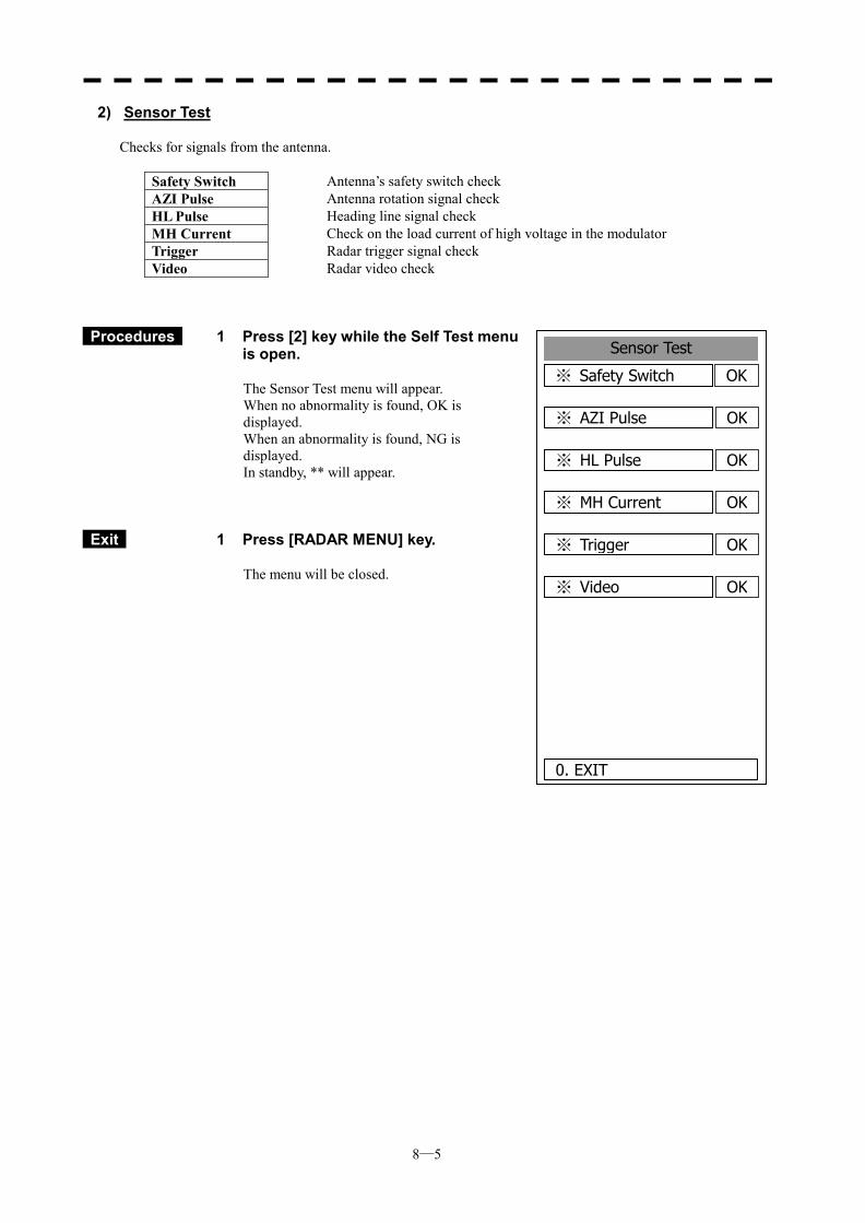
8─5
Sensor Test
OK※ Safety Switch
0. EXIT
OK※ AZI Pulse
OK※ HL Pulse
OK※ MH Current
OK※ Trigger
OK※ Video
2) Sensor Test
Checks for signals from the antenna.
Safety Switch Antenna’s safety switch check AZI Pulse Antenna rotation signal check HL Pulse Heading line signal check MH Current Check on the load current of high voltage in the modulator Trigger Radar trigger signal check Video
Radar video check
Procedures 1 Press [2] key while the Self Test menu is open.
The Sensor Test menu will appear. When no abnormality is found, OK is displayed. When an abnormality is found, NG is displayed. In standby, ** will appear.
Exit 1 Press [RADAR MENU] key.
The menu will be closed.
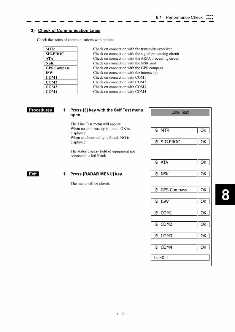
8─6
8
8.1 Performance Check ����
����
3) Check of Communication Lines
Check the status of communications with options.
MTR Check on connection with the transmitter-receiver SIG.PROC Check on connection with the signal processing circuit ATA Check on connection with the ARPA processing circuit NSK Check on connection with the NSK unit GPS Compass Check on connection with the GPS compass ISW Check on connection with the interswitch COM1 Check on connection with COM1 COM2 Check on connection with COM2 COM3 Check on connection with COM3 COM4
Check on connection with COM4
Procedures 1 Press [3] key with the Self Test menu open. The Line Test menu will appear. When no abnormality is found, OK is displayed. When an abnormality is found, NG is displayed. The status display field of equipment not connected is left blank.
Exit 1 Press [RADAR MENU] key.
The menu will be closed.
Line Test
OK※ MTR
0. EXIT
OK※ SIG.PROC
OK※ ATA
OK※ NSK
OK※ GPS Compass
OK※ ISW
OK※ COM1
OK※ COM2
OK※ COM3
OK※ COM4
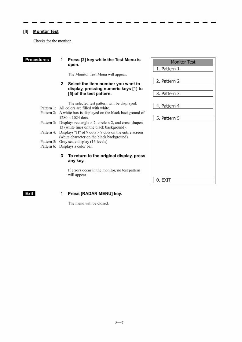
8─7
Monitor Test1. Pattern 1
2. Pattern 2
3. Pattern 3
4. Pattern 4
5. Pattern 5
0. EXIT
[II] Monitor Test
Checks for the monitor.
Procedures 1 Press [2] key while the Test Menu is open.
The Monitor Test Menu will appear.
2 Select the item number you want to display, pressing numeric keys [1] to [5] of the test pattern.
The selected test pattern will be displayed.
Pattern 1: All colors are filled with white. Pattern 2: A white box is displayed on the black background of
1280 � 1024 dots. Pattern 3: Displays rectangle � 2, circle � 2, and cross-shape�
13 (white lines on the black background). Pattern 4: Displays “H” of 9 dots � 9 dots on the entire screen
(white character on the black background). Pattern 5: Gray scale display (16 levels) Pattern 6: Displays a color bar.
3 To return to the original display, press
any key. If errors occur in the monitor, no test pattern will appear.
Exit 1 Press [RADAR MENU] key.
The menu will be closed.
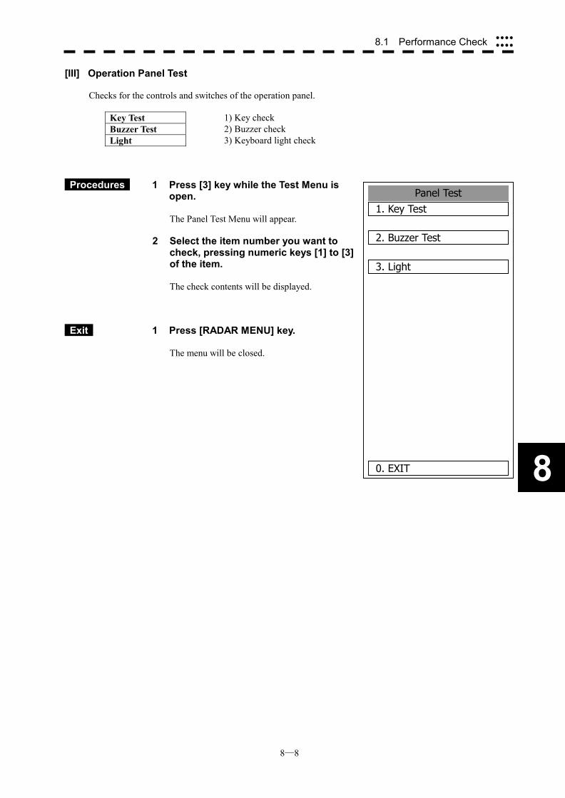
8─8
8
8.1 Performance Check ����
����
Panel Test1. Key Test
2. Buzzer Test
3. Light
0. EXIT
[III] Operation Panel Test
Checks for the controls and switches of the operation panel.
Key Test 1) Key check Buzzer Test 2) Buzzer check Light
3) Keyboard light check
Procedures 1 Press [3] key while the Test Menu is open.
The Panel Test Menu will appear.
2 Select the item number you want to check, pressing numeric keys [1] to [3] of the item.
The check contents will be displayed.
Exit 1 Press [RADAR MENU] key.
The menu will be closed.
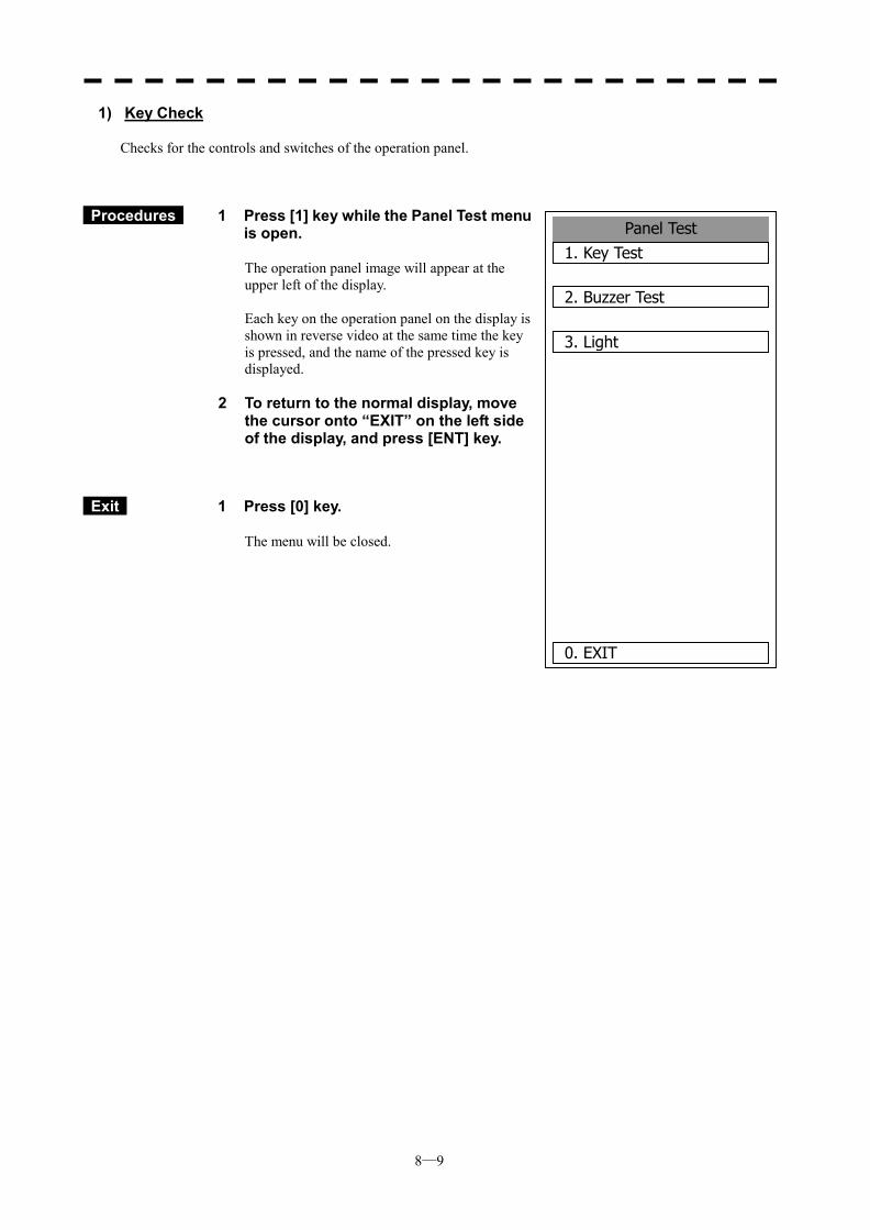
8─9
1) Key Check
Checks for the controls and switches of the operation panel.
Procedures 1 Press [1] key while the Panel Test menu is open.
The operation panel image will appear at the upper left of the display. Each key on the operation panel on the display is shown in reverse video at the same time the key is pressed, and the name of the pressed key is displayed.
2 To return to the normal display, move the cursor onto “EXIT” on the left side of the display, and press [ENT] key.
Exit 1 Press [0] key.
The menu will be closed.
Panel Test1. Key Test
2. Buzzer Test
3. Light
0. EXIT
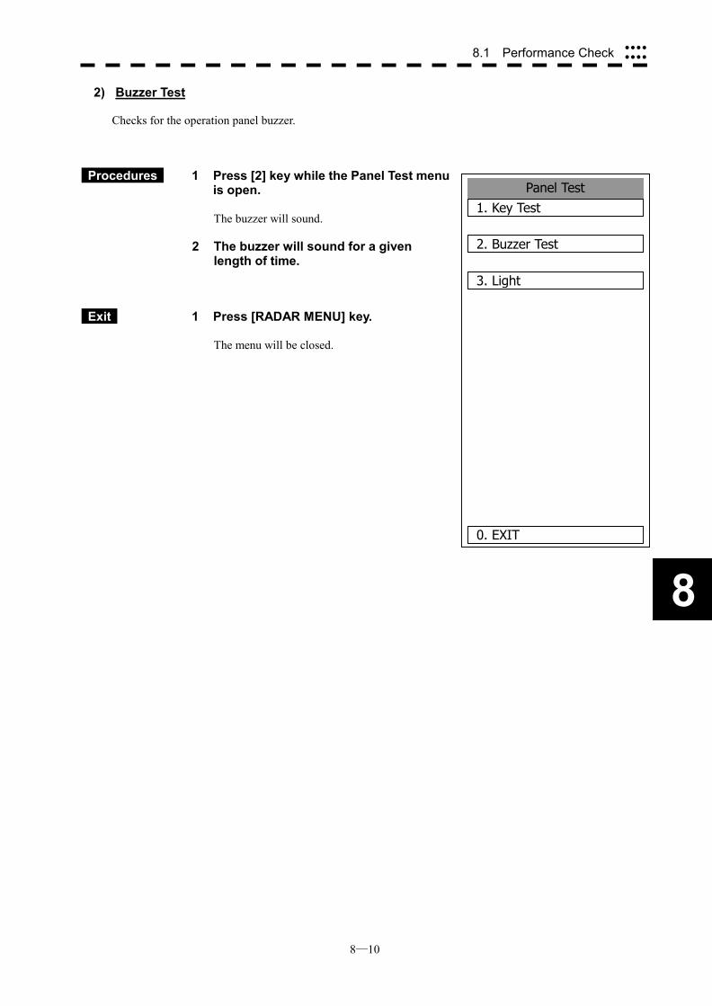
8─10
8
8.1 Performance Check ����
����
Panel Test1. Key Test
2. Buzzer Test
3. Light
0. EXIT
2) Buzzer Test
Checks for the operation panel buzzer.
Procedures 1 Press [2] key while the Panel Test menu is open.
The buzzer will sound.
2 The buzzer will sound for a given length of time.
Exit 1 Press [RADAR MENU] key.
The menu will be closed.
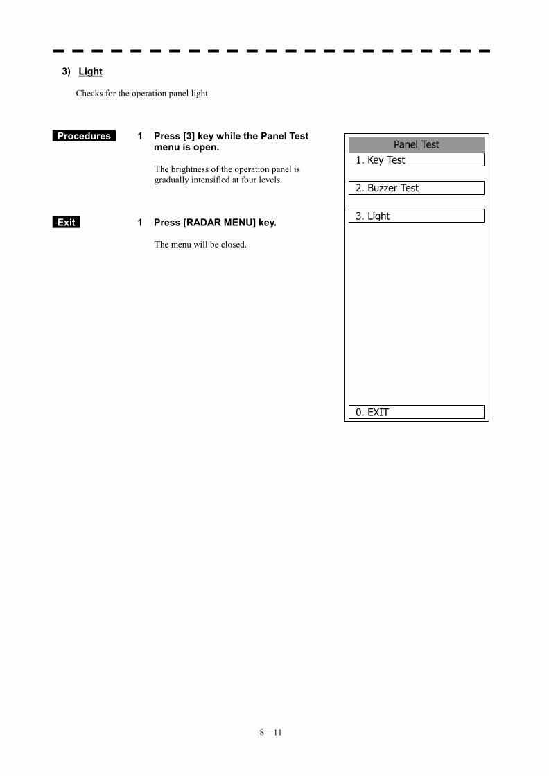
8─11
3) Light
Checks for the operation panel light.
Procedures 1 Press [3] key while the Panel Test menu is open.
The brightness of the operation panel is gradually intensified at four levels.
Exit 1 Press [RADAR MENU] key.
The menu will be closed.
Panel Test1. Key Test
2. Buzzer Test
3. Light
0. EXIT
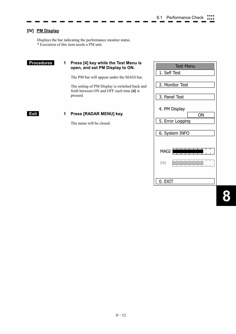
8─12
8
8.1 Performance Check ����
����
Test Menu1. Self Test
2. Monitor Test
3. Panel Test
4. PM DisplayON
5. Error Logging
6. System INFO
0. EXIT
MAGI
PM
[IV] PM Display
Displays the bar indicating the performance monitor status. * Execution of this item needs a PM unit.
Procedures 1 Press [4] key while the Test Menu is open, and set PM Display to ON.
The PM bar will appear under the MAGI bar. The setting of PM Display is switched back and forth between ON and OFF each time [4] is pressed.
Exit 1 Press [RADAR MENU] key.
The menu will be closed.
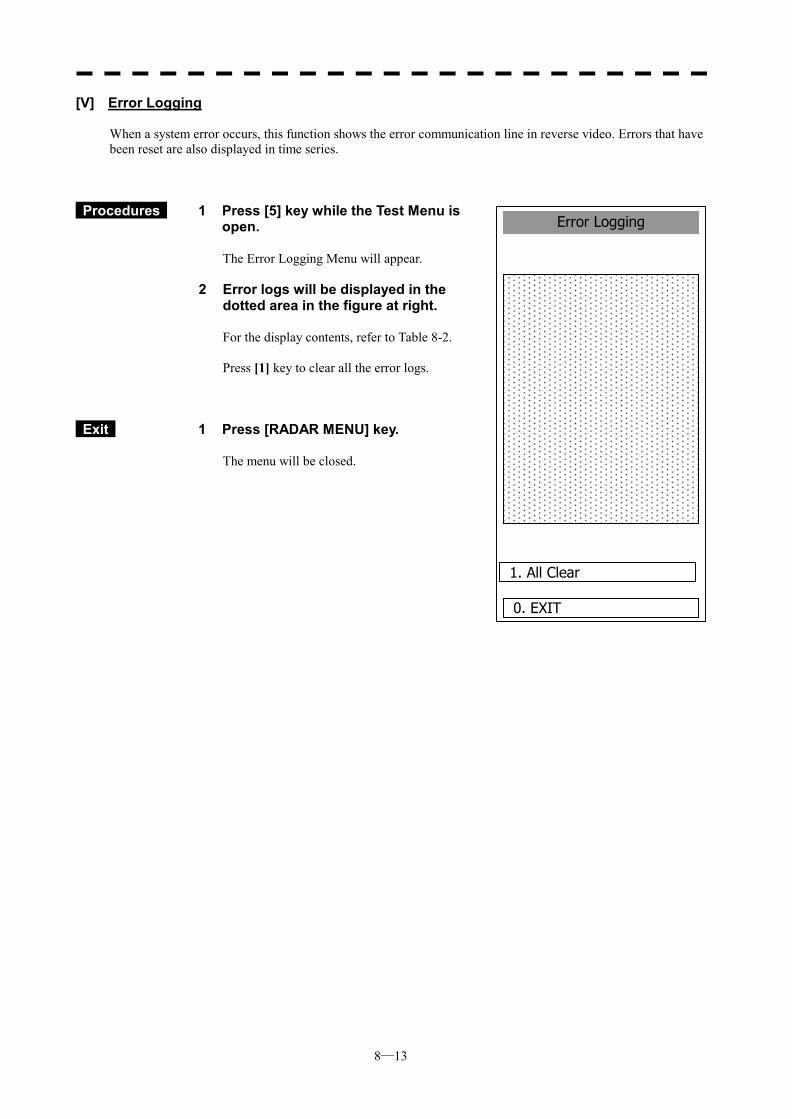
8─13
Error Logging
0. EXIT
1. All Clear
[V] Error Logging
When a system error occurs, this function shows the error communication line in reverse video. Errors that have been reset are also displayed in time series.
Procedures 1 Press [5] key while the Test Menu is open.
The Error Logging Menu will appear.
2 Error logs will be displayed in the dotted area in the figure at right.
For the display contents, refer to Table 8-2. Press [1] key to clear all the error logs.
Exit 1 Press [RADAR MENU] key.
The menu will be closed.
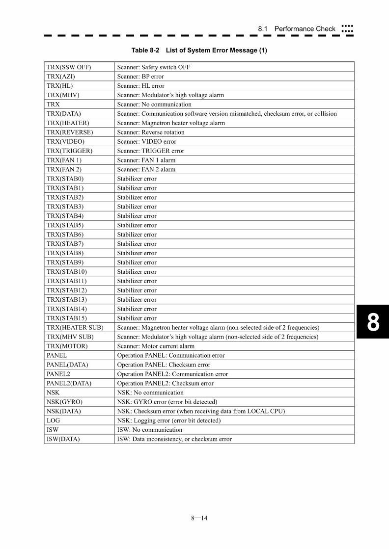
8─14
8
8.1 Performance Check ����
����
Table 8-2 List of System Error Message (1)
TRX(SSW OFF) Scanner: Safety switch OFF TRX(AZI) Scanner: BP error TRX(HL) Scanner: HL error TRX(MHV) Scanner: Modulator’s high voltage alarm TRX Scanner: No communication TRX(DATA) Scanner: Communication software version mismatched, checksum error, or collision TRX(HEATER) Scanner: Magnetron heater voltage alarm TRX(REVERSE) Scanner: Reverse rotation TRX(VIDEO) Scanner: VIDEO error TRX(TRIGGER) Scanner: TRIGGER error TRX(FAN 1) Scanner: FAN 1 alarm TRX(FAN 2) Scanner: FAN 2 alarm TRX(STAB0) Stabilizer error TRX(STAB1) Stabilizer error TRX(STAB2) Stabilizer error TRX(STAB3) Stabilizer error TRX(STAB4) Stabilizer error TRX(STAB5) Stabilizer error TRX(STAB6) Stabilizer error TRX(STAB7) Stabilizer error TRX(STAB8) Stabilizer error TRX(STAB9) Stabilizer error TRX(STAB10) Stabilizer error TRX(STAB11) Stabilizer error TRX(STAB12) Stabilizer error TRX(STAB13) Stabilizer error TRX(STAB14) Stabilizer error TRX(STAB15) Stabilizer error TRX(HEATER SUB) Scanner: Magnetron heater voltage alarm (non-selected side of 2 frequencies) TRX(MHV SUB) Scanner: Modulator’s high voltage alarm (non-selected side of 2 frequencies) TRX(MOTOR) Scanner: Motor current alarm PANEL Operation PANEL: Communication error PANEL(DATA) Operation PANEL: Checksum error PANEL2 Operation PANEL2: Communication error PANEL2(DATA) Operation PANEL2: Checksum error NSK NSK: No communication NSK(GYRO) NSK: GYRO error (error bit detected) NSK(DATA) NSK: Checksum error (when receiving data from LOCAL CPU) LOG NSK: Logging error (error bit detected) ISW ISW: No communication ISW(DATA) ISW: Data inconsistency, or checksum error
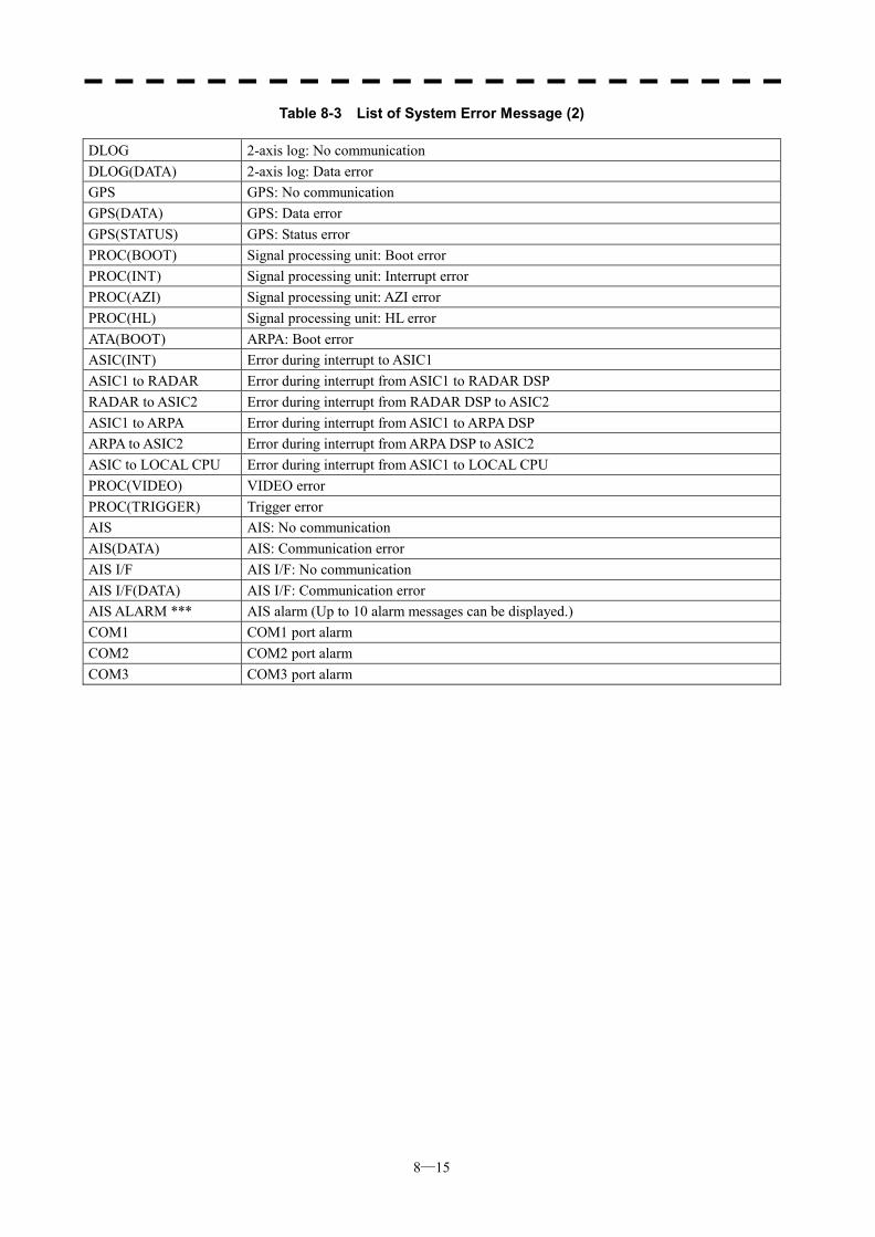
8─15
Table 8-3 List of System Error Message (2)
DLOG 2-axis log: No communication DLOG(DATA) 2-axis log: Data error GPS GPS: No communication GPS(DATA) GPS: Data error GPS(STATUS) GPS: Status error PROC(BOOT) Signal processing unit: Boot error PROC(INT) Signal processing unit: Interrupt error PROC(AZI) Signal processing unit: AZI error PROC(HL) Signal processing unit: HL error ATA(BOOT) ARPA: Boot error ASIC(INT) Error during interrupt to ASIC1 ASIC1 to RADAR Error during interrupt from ASIC1 to RADAR DSP RADAR to ASIC2 Error during interrupt from RADAR DSP to ASIC2 ASIC1 to ARPA Error during interrupt from ASIC1 to ARPA DSP ARPA to ASIC2 Error during interrupt from ARPA DSP to ASIC2 ASIC to LOCAL CPU Error during interrupt from ASIC1 to LOCAL CPU PROC(VIDEO) VIDEO error PROC(TRIGGER) Trigger error AIS AIS: No communication AIS(DATA) AIS: Communication error AIS I/F AIS I/F: No communication AIS I/F(DATA) AIS I/F: Communication error AIS ALARM *** AIS alarm (Up to 10 alarm messages can be displayed.) COM1 COM1 port alarm COM2 COM2 port alarm COM3 COM3 port alarm
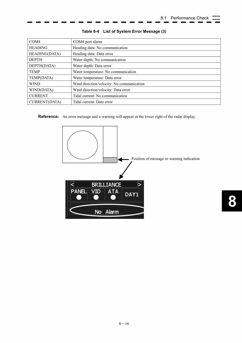
8─16
8
8.1 Performance Check ����
����
Table 8-4 List of System Error Message (3)
COM4 COM4 port alarm HEADING Heading data: No communication HEADING(DATA) Heading data: Data error DEPTH Water depth: No communication DEPTH(DATA) Water depth: Data error TEMP Water temperature: No communication TEMP(DATA) Water temperature: Data error WIND Wind direction/velocity: No communication WIND(DATA) Wind direction/velocity: Data error CURRENT Tidal current: No communication CURRENT(DATA) Tidal current: Data error
Reference: An error message and a warning will appear at the lower right of the radar display.
Position of message or warning indication
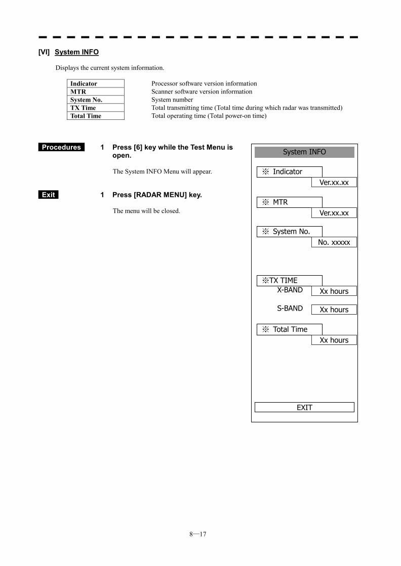
8─17
System INFO
※ Indicator Ver.xx.xx
EXIT
※ MTR Ver.xx.xx
※ System No. No. xxxxx
※TX TIME Xx hoursX-BAND
Xx hoursS-BAND
※ Total Time Xx hours
[VI] System INFO
Displays the current system information.
Indicator Processor software version information MTR Scanner software version information System No. System number TX Time Total transmitting time (Total time during which radar was transmitted) Total Time
Total operating time (Total power-on time)
Procedures 1 Press [6] key while the Test Menu is open.
The System INFO Menu will appear.
Exit 1 Press [RADAR MENU] key.
The menu will be closed.
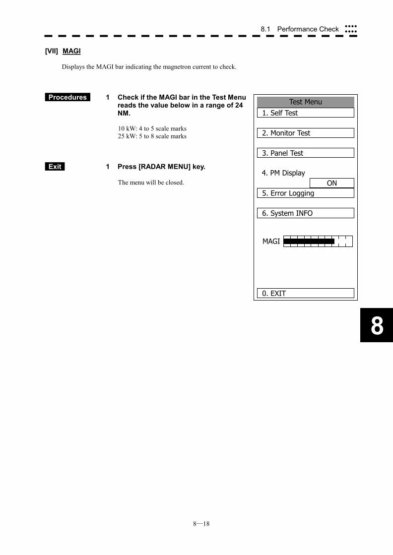
8─18
8
8.1 Performance Check ����
����
Test Menu1. Self Test
2. Monitor Test
3. Panel Test
4. PM DisplayON
5. Error Logging
6. System INFO
0. EXIT
MAGI
[VII] MAGI
Displays the MAGI bar indicating the magnetron current to check.
Procedures 1 Check if the MAGI bar in the Test Menu reads the value below in a range of 24 NM. 10 kW: 4 to 5 scale marks 25 kW: 5 to 8 scale marks
Exit 1 Press [RADAR MENU] key.
The menu will be closed.
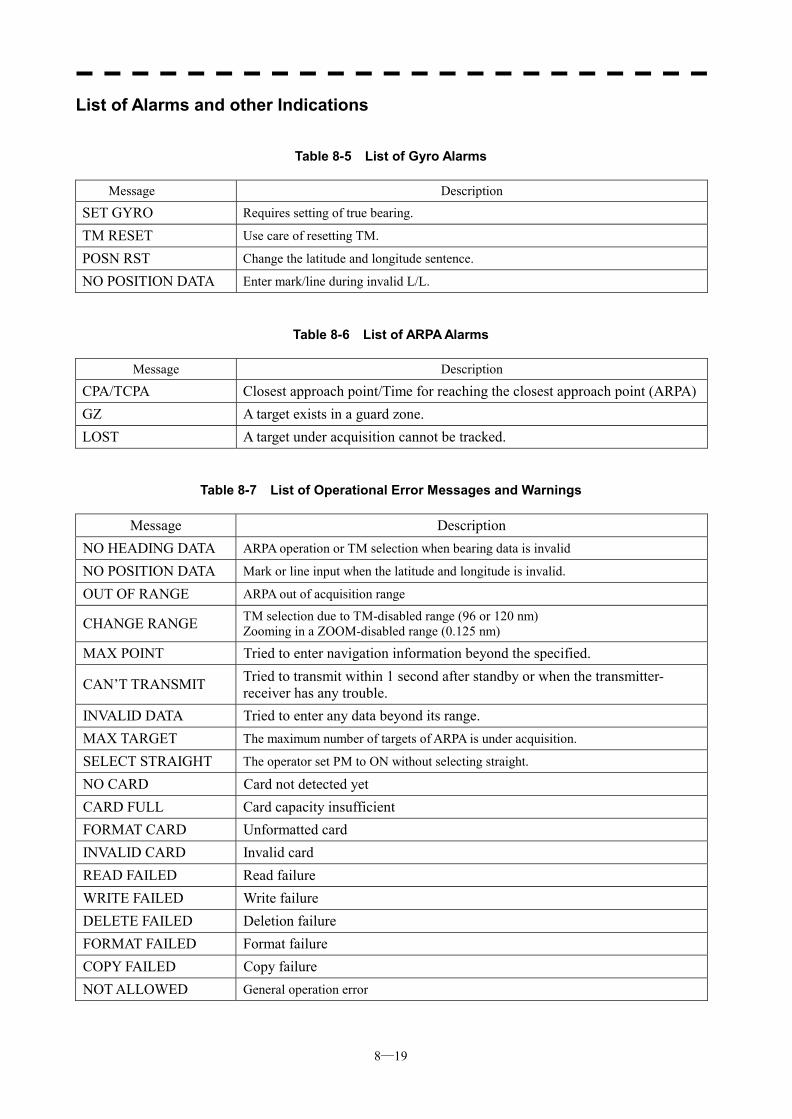
8─19
List of Alarms and other Indications
Table 8-5 List of Gyro Alarms
Message Description
SET GYRO Requires setting of true bearing.
TM RESET Use care of resetting TM.
POSN RST Change the latitude and longitude sentence.
NO POSITION DATA Enter mark/line during invalid L/L.
Table 8-6 List of ARPA Alarms
Message Description
CPA/TCPA Closest approach point/Time for reaching the closest approach point (ARPA)GZ A target exists in a guard zone. LOST A target under acquisition cannot be tracked.
Table 8-7 List of Operational Error Messages and Warnings
Message Description NO HEADING DATA ARPA operation or TM selection when bearing data is invalid
NO POSITION DATA Mark or line input when the latitude and longitude is invalid.
OUT OF RANGE ARPA out of acquisition range
CHANGE RANGE TM selection due to TM-disabled range (96 or 120 nm) Zooming in a ZOOM-disabled range (0.125 nm)
MAX POINT Tried to enter navigation information beyond the specified.
CAN’T TRANSMIT Tried to transmit within 1 second after standby or when the transmitter- receiver has any trouble.
INVALID DATA Tried to enter any data beyond its range. MAX TARGET The maximum number of targets of ARPA is under acquisition.
SELECT STRAIGHT The operator set PM to ON without selecting straight.
NO CARD Card not detected yet CARD FULL Card capacity insufficient FORMAT CARD Unformatted card INVALID CARD Invalid card READ FAILED Read failure WRITE FAILED Write failure DELETE FAILED Deletion failure FORMAT FAILED Format failure COPY FAILED Copy failure NOT ALLOWED General operation error
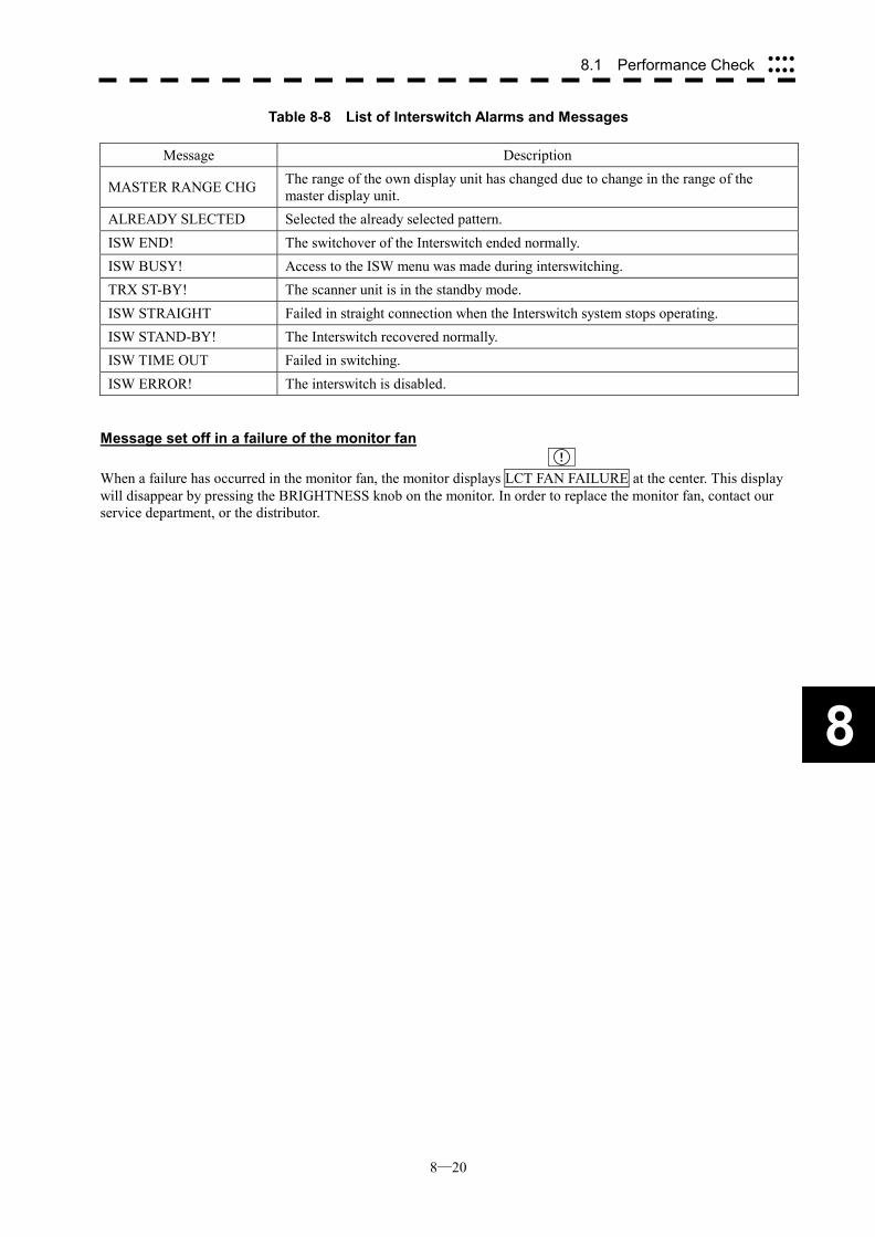
8─20
8
8.1 Performance Check ����
����
Table 8-8 List of Interswitch Alarms and Messages
Message Description
MASTER RANGE CHG The range of the own display unit has changed due to change in the range of the master display unit.
ALREADY SLECTED Selected the already selected pattern. ISW END! The switchover of the Interswitch ended normally. ISW BUSY! Access to the ISW menu was made during interswitching. TRX ST-BY! The scanner unit is in the standby mode. ISW STRAIGHT Failed in straight connection when the Interswitch system stops operating. ISW STAND-BY! The Interswitch recovered normally. ISW TIME OUT Failed in switching. ISW ERROR! The interswitch is disabled.
Message set off in a failure of the monitor fan ! When a failure has occurred in the monitor fan, the monitor displays LCT FAN FAILURE at the center. This display will disappear by pressing the BRIGHTNESS knob on the monitor. In order to replace the monitor fan, contact our service department, or the distributor.
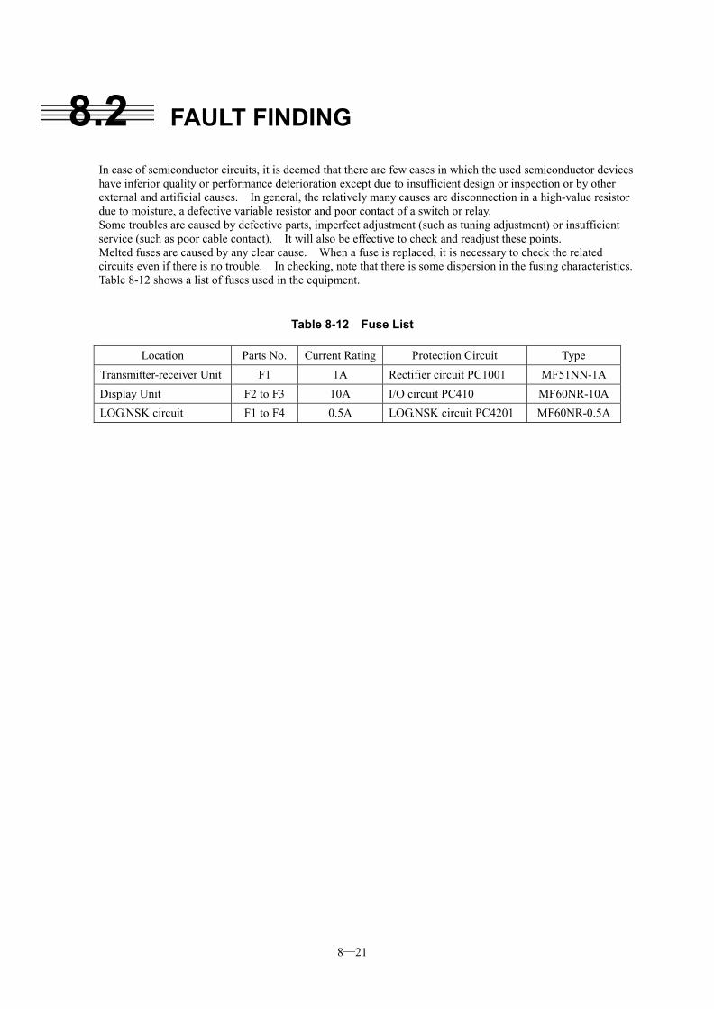
8─21
8.2 FAULT FINDING
In case of semiconductor circuits, it is deemed that there are few cases in which the used semiconductor devices have inferior quality or performance deterioration except due to insufficient design or inspection or by other external and artificial causes. In general, the relatively many causes are disconnection in a high-value resistor due to moisture, a defective variable resistor and poor contact of a switch or relay. Some troubles are caused by defective parts, imperfect adjustment (such as tuning adjustment) or insufficient service (such as poor cable contact). It will also be effective to check and readjust these points. Melted fuses are caused by any clear cause. When a fuse is replaced, it is necessary to check the related circuits even if there is no trouble. In checking, note that there is some dispersion in the fusing characteristics. Table 8-12 shows a list of fuses used in the equipment.
Table 8-12 Fuse List
Location Parts No. Current Rating Protection Circuit Type Transmitter-receiver Unit F1 1A Rectifier circuit PC1001 MF51NN-1A Display Unit F2 to F3 10A I/O circuit PC410 MF60NR-10A LOG.NSK circuit F1 to F4 0.5A LOG.NSK circuit PC4201 MF60NR-0.5A
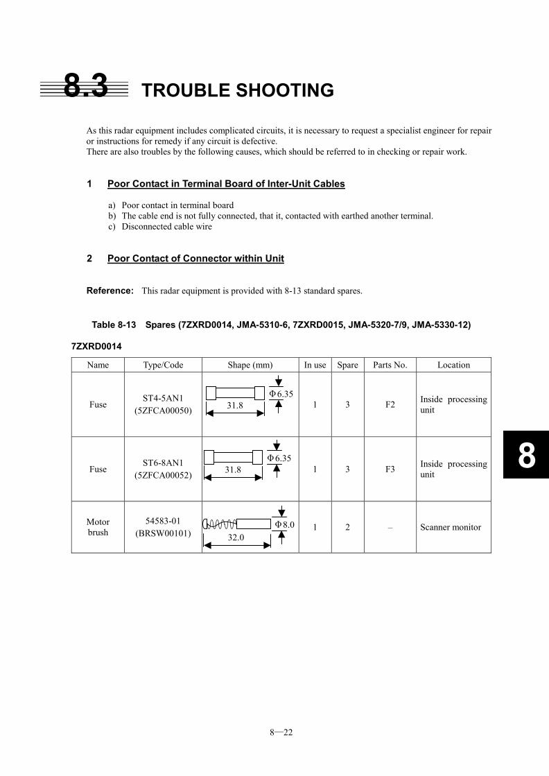
8─22
8
8.3 TROUBLE SHOOTING
As this radar equipment includes complicated circuits, it is necessary to request a specialist engineer for repair or instructions for remedy if any circuit is defective. There are also troubles by the following causes, which should be referred to in checking or repair work.
1 Poor Contact in Terminal Board of Inter-Unit Cables a) Poor contact in terminal board b) The cable end is not fully connected, that it, contacted with earthed another terminal. c) Disconnected cable wire
2 Poor Contact of Connector within Unit
Reference: This radar equipment is provided with 8-13 standard spares.
Table 8-13 Spares (7ZXRD0014, JMA-5310-6, 7ZXRD0015, JMA-5320-7/9, JMA-5330-12)
7ZXRD0014
Name Type/Code Shape (mm) In use Spare Parts No. Location
Fuse ST4-5AN1
(5ZFCA00050)
1 3 F2 Inside processing unit
Fuse ST6-8AN1
(5ZFCA00052)
1 3 F3 Inside processing unit
Motor brush
54583-01 (BRSW00101)
1 2 – Scanner monitor
31.8 Φ6.35
31.8 Φ6.35
32.0 Φ8.0
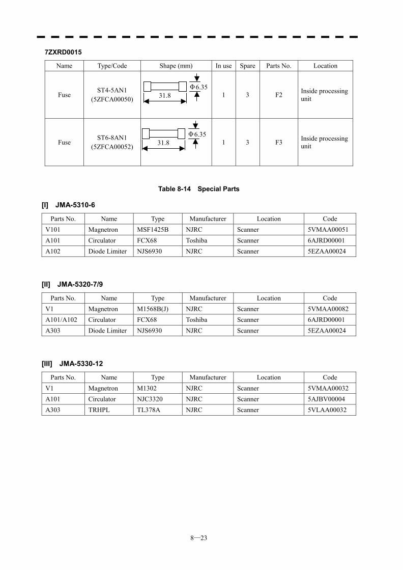
8─23
7ZXRD0015
Name Type/Code Shape (mm) In use Spare Parts No. Location
Fuse ST4-5AN1
(5ZFCA00050)
1 3 F2 Inside processing unit
Fuse ST6-8AN1
(5ZFCA00052)
1 3 F3 Inside processing unit
Table 8-14 Special Parts
[I] JMA-5310-6
Parts No. Name Type Manufacturer Location Code V101 Magnetron MSF1425B NJRC Scanner 5VMAA00051 A101 Circulator FCX68 Toshiba Scanner 6AJRD00001 A102 Diode Limiter NJS6930 NJRC Scanner 5EZAA00024
[II] JMA-5320-7/9
Parts No. Name Type Manufacturer Location Code V1 Magnetron M1568B(J) NJRC Scanner 5VMAA00082 A101/A102 Circulator FCX68 Toshiba Scanner 6AJRD00001 A303 Diode Limiter NJS6930 NJRC Scanner 5EZAA00024
[III] JMA-5330-12
Parts No. Name Type Manufacturer Location Code V1 Magnetron M1302 NJRC Scanner 5VMAA00032 A101 Circulator NJC3320 NJRC Scanner 5AJBV00004 A303 TRHPL TL378A NJRC Scanner 5VLAA00032
31.8 Φ6.35
31.8 Φ6.35
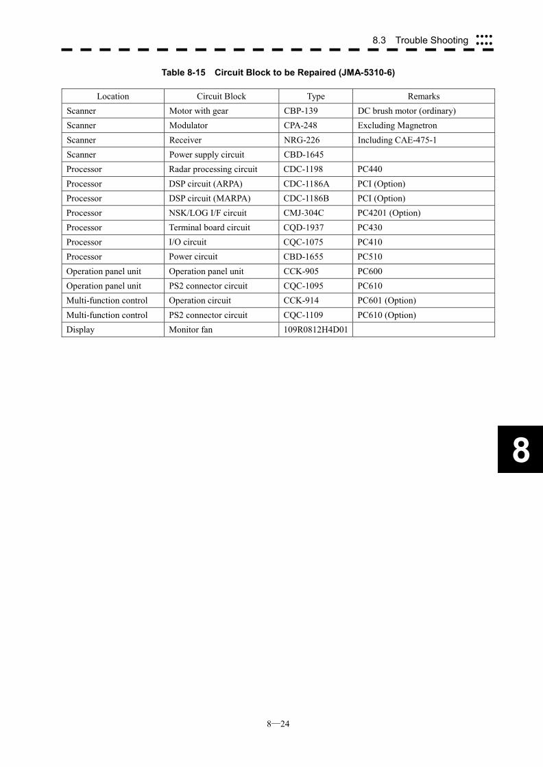
8─24
8.3 Trouble Shooting ����
����
8
Table 8-15 Circuit Block to be Repaired (JMA-5310-6)
Location Circuit Block Type Remarks Scanner Motor with gear CBP-139 DC brush motor (ordinary) Scanner Modulator CPA-248 Excluding Magnetron Scanner Receiver NRG-226 Including CAE-475-1 Scanner Power supply circuit CBD-1645 Processor Radar processing circuit CDC-1198 PC440 Processor DSP circuit (ARPA) CDC-1186A PCI (Option) Processor DSP circuit (MARPA) CDC-1186B PCI (Option) Processor NSK/LOG I/F circuit CMJ-304C PC4201 (Option) Processor Terminal board circuit CQD-1937 PC430 Processor I/O circuit CQC-1075 PC410 Processor Power circuit CBD-1655 PC510 Operation panel unit Operation panel unit CCK-905 PC600 Operation panel unit PS2 connector circuit CQC-1095 PC610 Multi-function control Operation circuit CCK-914 PC601 (Option) Multi-function control PS2 connector circuit CQC-1109 PC610 (Option) Display Monitor fan 109R0812H4D01
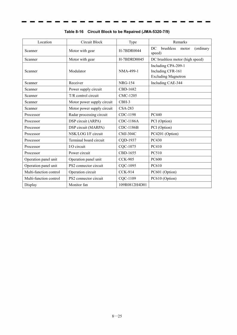
8─25
Table 8-16 Circuit Block to be Repaired (JMA-5320-7/9)
Location Circuit Block Type Remarks
Scanner Motor with gear H-7BDR0044 DC brushless motor (ordinary speed)
Scanner Motor with gear H-7BDRD0045 DC brushless motor (high speed)
Scanner Modulator NMA-499-1 Including CPA-209-1 Including CFR-161 Excluding Magnetron
Scanner Receiver NRG-154 Including CAE-344 Scanner Power supply circuit CBD-1682 Scanner T/R control circuit CMC-1205 Scanner Motor power supply circuit CBH-3 Scanner Motor power supply circuit CSA-283 Processor Radar processing circuit CDC-1198 PC440 Processor DSP circuit (ARPA) CDC-1186A PCI (Option) Processor DSP circuit (MARPA) CDC-1186B PCI (Option) Processor NSK/LOG I/F circuit CMJ-304C PC4201 (Option) Processor Terminal board circuit CQD-1937 PC430 Processor I/O circuit CQC-1075 PC410 Processor Power circuit CBD-1655 PC510 Operation panel unit Operation panel unit CCK-905 PC600 Operation panel unit PS2 connector circuit CQC-1095 PC610 Multi-function control Operation circuit CCK-914 PC601 (Option) Multi-function control PS2 connector circuit CQC-1109 PC610 (Option) Display Monitor fan 109R0812H4D01
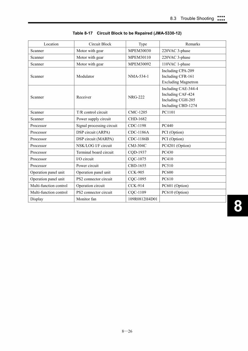
8─26
8.3 Trouble Shooting ����
����
8
Table 8-17 Circuit Block to be Repaired (JMA-5330-12)
Location Circuit Block Type Remarks Scanner Motor with gear MPEM30030 220VAC 3-phase Scanner Motor with gear MPEM30110 220VAC 3-phase Scanner Motor with gear MPEM30092 110VAC 1-phase
Scanner Modulator NMA-534-1 Including CPA-209 Including CFR-161 Excluding Magnetron
Scanner Receiver NRG-222
Including CAE-344-4 Including CAF-424 Including CGH-205 Including CBD-1274
Scanner T/R control circuit CMC-1205 PC1101 Scanner Power supply circuit CHD-1682 Processor Signal processing circuit CDC-1198 PC440 Processor DSP circuit (ARPA) CDC-1186A PCI (Option) Processor DSP circuit (MARPA) CDC-1186B PCI (Option) Processor NSK/LOG I/F circuit CMJ-304C PC4201 (Option) Processor Terminal board circuit CQD-1937 PC430 Processor I/O circuit CQC-1075 PC410 Processor Power circuit CBD-1655 PC510 Operation panel unit Operation panel unit CCK-905 PC600 Operation panel unit PS2 connector circuit CQC-1095 PC610 Multi-function control Operation circuit CCK-914 PC601 (Option) Multi-function control PS2 connector circuit CQC-1109 PC610 (Option) Display Monitor fan 109R0812H4D01
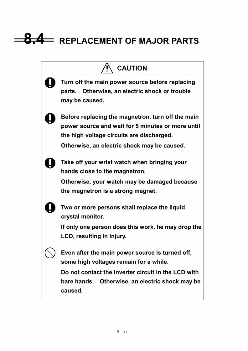
8─27
8.4 REPLACEMENT OF MAJOR PARTS
CAUTION
Turn off the main power source before replacing parts. Otherwise, an electric shock or trouble may be caused.
Before replacing the magnetron, turn off the main power source and wait for 5 minutes or more until the high voltage circuits are discharged. Otherwise, an electric shock may be caused.
Take off your wrist watch when bringing your hands close to the magnetron. Otherwise, your watch may be damaged because the magnetron is a strong magnet.
Two or more persons shall replace the liquid crystal monitor. If only one person does this work, he may drop the LCD, resulting in injury.
Even after the main power source is turned off, some high voltages remain for a while.
Do not contact the inverter circuit in the LCD with bare hands. Otherwise, an electric shock may be caused.
8─28
8.4 Replacement of Major Parts ����
����
8
Parts Required for Periodic Replacement Here are parts required for periodic replacement
Part name Interval
1. Magnetron 4000 hours 2. Motor 10000 hours 3. LCD backlight 50000 hours 4. Fan motor 20000 hours 5. Backup battery 3 years
Replacement of magnetron (V1/V201)
Remove the shield cover of the modulator and check that no charge remains in the high-voltage modulator circuit. Then, remove the socket of the magnetron. The magnetron can be demounted by removing the screws fixing it. When mounting a new magnetron, do not touch the magnet with a screwdriver or put it on an iron plate. After replacement, connect the lead wire correctly. Handling of Magnetron under Long-Time Storage The magnetron that has been kept in storage for a long time may cause sparks and operate unstably when its operation is started. Perform the aging in the following procedures: (1) Warm up the cathode for a longer time than usually. (20 to 30 minutes in the STBY state.) (2) Start the operation from the short pulse range and shift it gradually to the longer pulse ranges. If the
operation becomes unstable during this process, return it to the standby mode immediately. Keep the state for 5 to 10 minutes until the operation is restarted.
Replacement of TRHPL (A303)(JMA-5330-12) Remove the 4 screws fixing the TRHPL with receiver and remove the TRHPL. When mounting the TRHPL, take care of the mounting direction and mount it in the arrow direction facing it the receiver front end.
Replacement of Diode Limiter (A303)(JMA-5310-6, JMA-5320-7/9) Remove the 4 screws fixing the receiver. Remove the 4 screws fixing the diode and the limiter, and remove diode limiter. When mounting the diode limiter, take care of the mounting direction and mount it in the arrow direction facing it the receiver front end. Connect the wiring in the same way as before the replacement.
8─29
Replacement of LCD Monitor 1 JMA-5310-6, JMA-5320-7/9, JMA-5330-12 (Display Unit: NCD-4510) (1) Disconnect the cables from the connectors “VIDEO” and “VIDEO DC OUT” on the rear of the processor. (2) Softly place the LCD monitor on a desk covered with a soft cloth. (3) Attach a new LC monitor in the reverse sequence as described above.
��When replacing the LCD monitor, which is easily broken by a little impact, handle it carefully and do not hit any article against it or put it on a hard article.
Attention
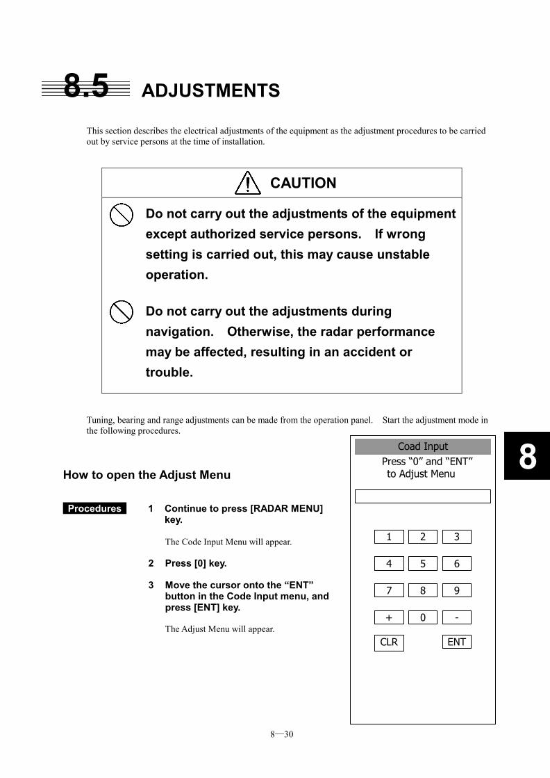
8─30
8Coad InputPress “0” and “ENT” to Adjust Menu
1 2 3
4 5 6
7 8 9
+ 0 -
CLR ENT
8.5 ADJUSTMENTS This section describes the electrical adjustments of the equipment as the adjustment procedures to be carried out by service persons at the time of installation.
CAUTION
Do not carry out the adjustments of the equipment except authorized service persons. If wrong setting is carried out, this may cause unstable operation.
Do not carry out the adjustments during navigation. Otherwise, the radar performance may be affected, resulting in an accident or trouble.
Tuning, bearing and range adjustments can be made from the operation panel. Start the adjustment mode in the following procedures.
How to open the Adjust Menu
Procedures 1 Continue to press [RADAR MENU] key.
The Code Input Menu will appear.
2 Press [0] key.
3 Move the cursor onto the “ENT” button in the Code Input menu, and press [ENT] key. The Adjust Menu will appear.
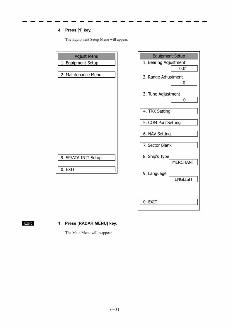
8─31
4 Press [1] key.
The Equipment Setup Menu will appear.
Exit 1 Press [RADAR MENU] key.
The Main Menu will reappear.
Adjust Menu1. Equipment Setup
2. Maintenance Menu
9. SP/ATA INIT Setup
0. EXIT
Equipment Setup1. Bearing Adjustment
0.0°
2. Range Adjustment0
0
8. Ship’s Type
0. EXIT
3. Tune Adjustment
4. TRX Setting
5. COM Port Setting
6. NAV Setting
7. Sector Blank
MERCHANT
9. LanguageENGLISH
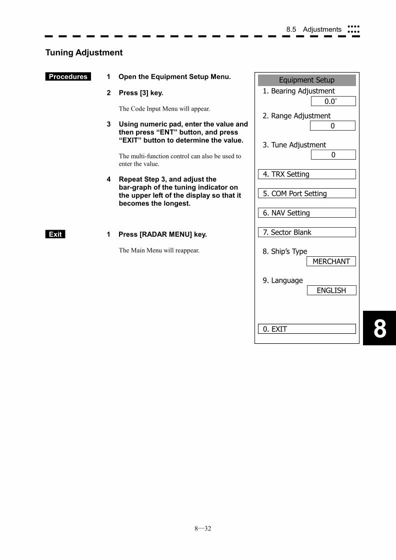
8─32
8.5 Adjustments ����
����
8
Equipment Setup1. Bearing Adjustment
0.0°
2. Range Adjustment0
0
8. Ship’s Type
0. EXIT
3. Tune Adjustment
4. TRX Setting
5. COM Port Setting
6. NAV Setting
7. Sector Blank
MERCHANT
9. LanguageENGLISH
Tuning Adjustment
Procedures 1 Open the Equipment Setup Menu. 2 Press [3] key.
The Code Input Menu will appear.
3 Using numeric pad, enter the value and then press “ENT” button, and press “EXIT” button to determine the value.
The multi-function control can also be used to enter the value.
4 Repeat Step 3, and adjust the bar-graph of the tuning indicator on the upper left of the display so that it becomes the longest.
Exit 1 Press [RADAR MENU] key.
The Main Menu will reappear.
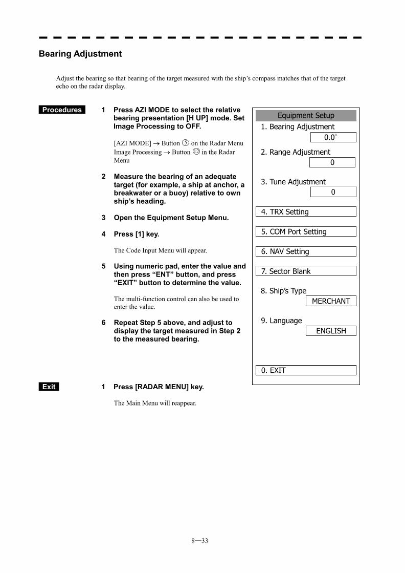
8─33
Equipment Setup1. Bearing Adjustment
0.0°
2. Range Adjustment0
0
8. Ship’s Type
0. EXIT
3. Tune Adjustment
4. TRX Setting
5. COM Port Setting
6. NAV Setting
7. Sector Blank
MERCHANT
9. LanguageENGLISH
Bearing Adjustment
Adjust the bearing so that bearing of the target measured with the ship’s compass matches that of the target echo on the radar display.
Procedures 1 Press AZI MODE to select the relative bearing presentation [H UP] mode. Set Image Processing to OFF.
[AZI MODE] � Button 5 on the Radar Menu Image Processing � Button 12 in the Radar Menu
2 Measure the bearing of an adequate
target (for example, a ship at anchor, a breakwater or a buoy) relative to own ship’s heading.
3 Open the Equipment Setup Menu. 4 Press [1] key.
The Code Input Menu will appear.
5 Using numeric pad, enter the value and then press “ENT” button, and press “EXIT” button to determine the value.
The multi-function control can also be used to enter the value.
6 Repeat Step 5 above, and adjust to display the target measured in Step 2 to the measured bearing.
Exit 1 Press [RADAR MENU] key.
The Main Menu will reappear.
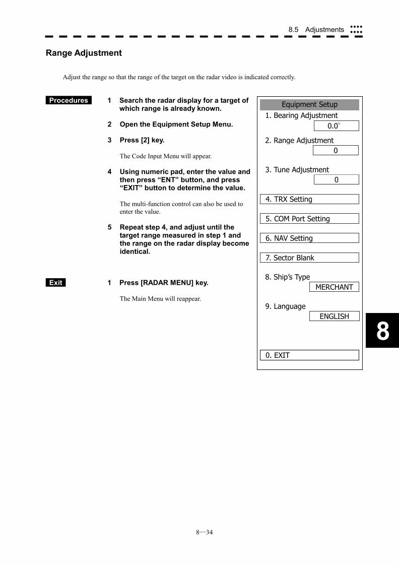
8─34
8.5 Adjustments ����
����
8
Equipment Setup1. Bearing Adjustment
0.0°
2. Range Adjustment0
0
8. Ship’s Type
0. EXIT
3. Tune Adjustment
4. TRX Setting
5. COM Port Setting
6. NAV Setting
7. Sector Blank
MERCHANT
9. LanguageENGLISH
Range Adjustment
Adjust the range so that the range of the target on the radar video is indicated correctly.
Procedures 1 Search the radar display for a target of which range is already known.
2 Open the Equipment Setup Menu.
3 Press [2] key.
The Code Input Menu will appear.
4 Using numeric pad, enter the value and then press “ENT” button, and press “EXIT” button to determine the value.
The multi-function control can also be used to enter the value.
5 Repeat step 4, and adjust until the target range measured in step 1 and the range on the radar display become identical.
Exit 1 Press [RADAR MENU] key.
The Main Menu will reappear.
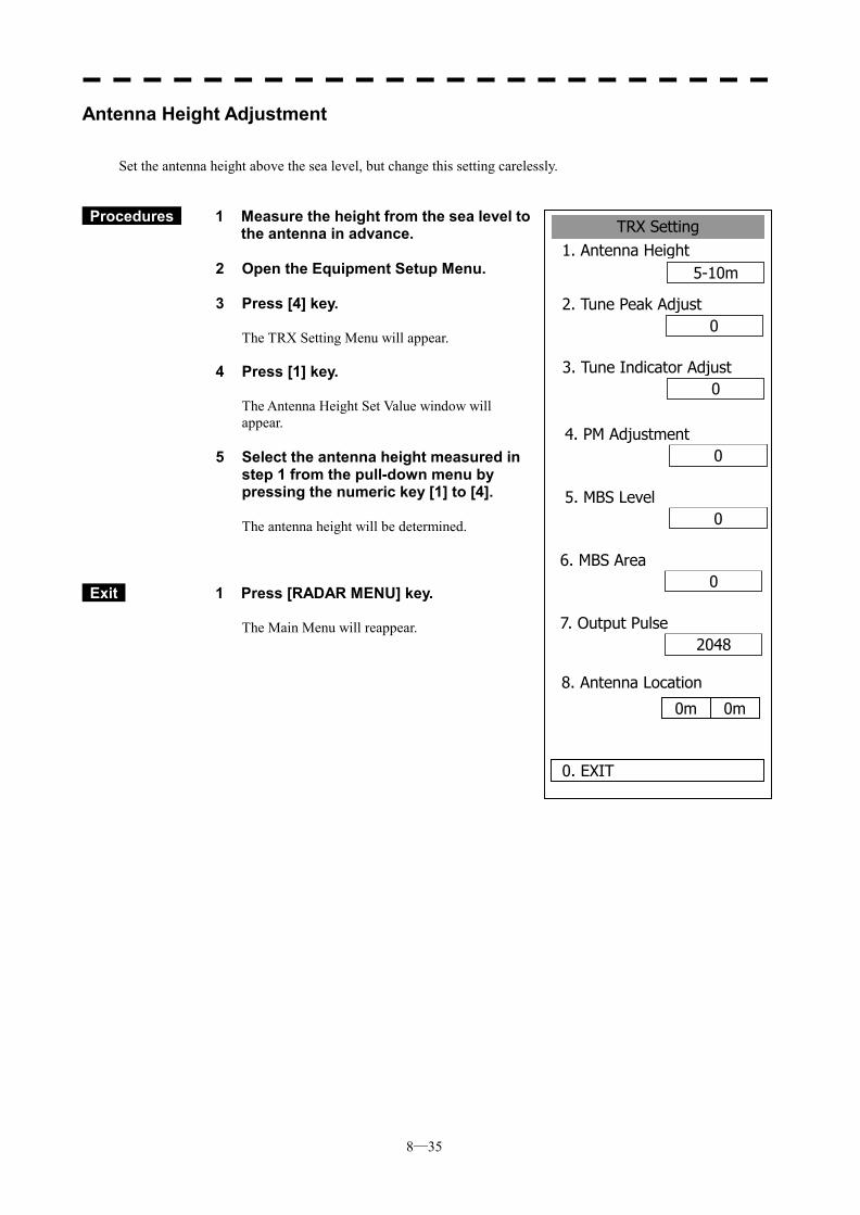
8─35
TRX Setting1. Antenna Height
5-10m
2. Tune Peak Adjust0
0
8. Antenna Location
3. Tune Indicator Adjust
04. PM Adjustment
05. MBS Level
06. MBS Area
20487. Output Pulse
0m 0m
0. EXIT
Antenna Height Adjustment
Set the antenna height above the sea level, but change this setting carelessly.
Procedures 1 Measure the height from the sea level to the antenna in advance.
2 Open the Equipment Setup Menu. 3 Press [4] key.
The TRX Setting Menu will appear.
4 Press [1] key.
The Antenna Height Set Value window will appear.
5 Select the antenna height measured in
step 1 from the pull-down menu by pressing the numeric key [1] to [4].
The antenna height will be determined.
Exit 1 Press [RADAR MENU] key.
The Main Menu will reappear.
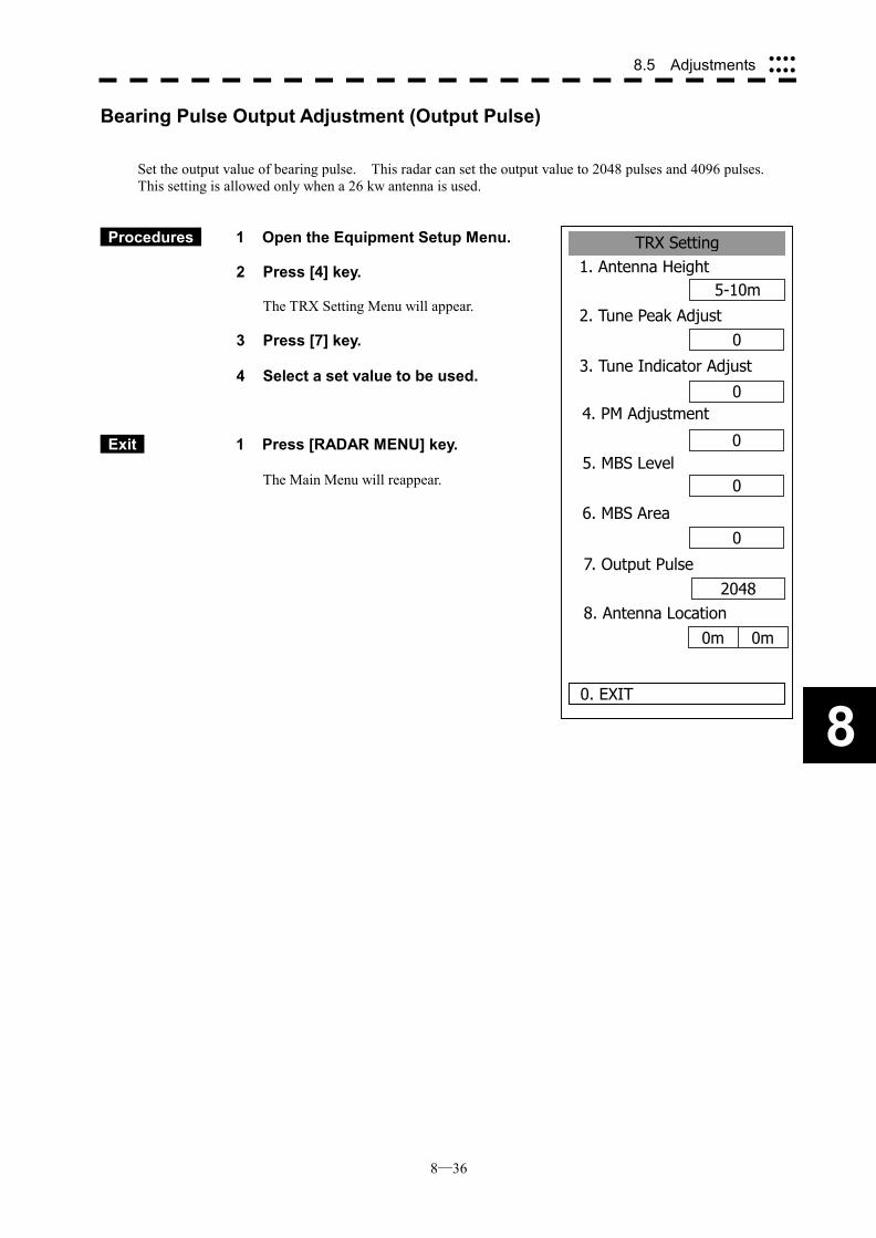
8─36
8.5 Adjustments ����
����
8
TRX Setting1. Antenna Height
5-10m
2. Tune Peak Adjust0
0
0. EXIT
3. Tune Indicator Adjust
0
4. PM Adjustment
5. MBS Level
0
6. MBS Area0
7. Output Pulse2048
8. Antenna Location0m 0m
0
Bearing Pulse Output Adjustment (Output Pulse)
Set the output value of bearing pulse. This radar can set the output value to 2048 pulses and 4096 pulses. This setting is allowed only when a 26 kw antenna is used.
Procedures 1 Open the Equipment Setup Menu.
2 Press [4] key. The TRX Setting Menu will appear.
3 Press [7] key. 4 Select a set value to be used.
Exit 1 Press [RADAR MENU] key.
The Main Menu will reappear.
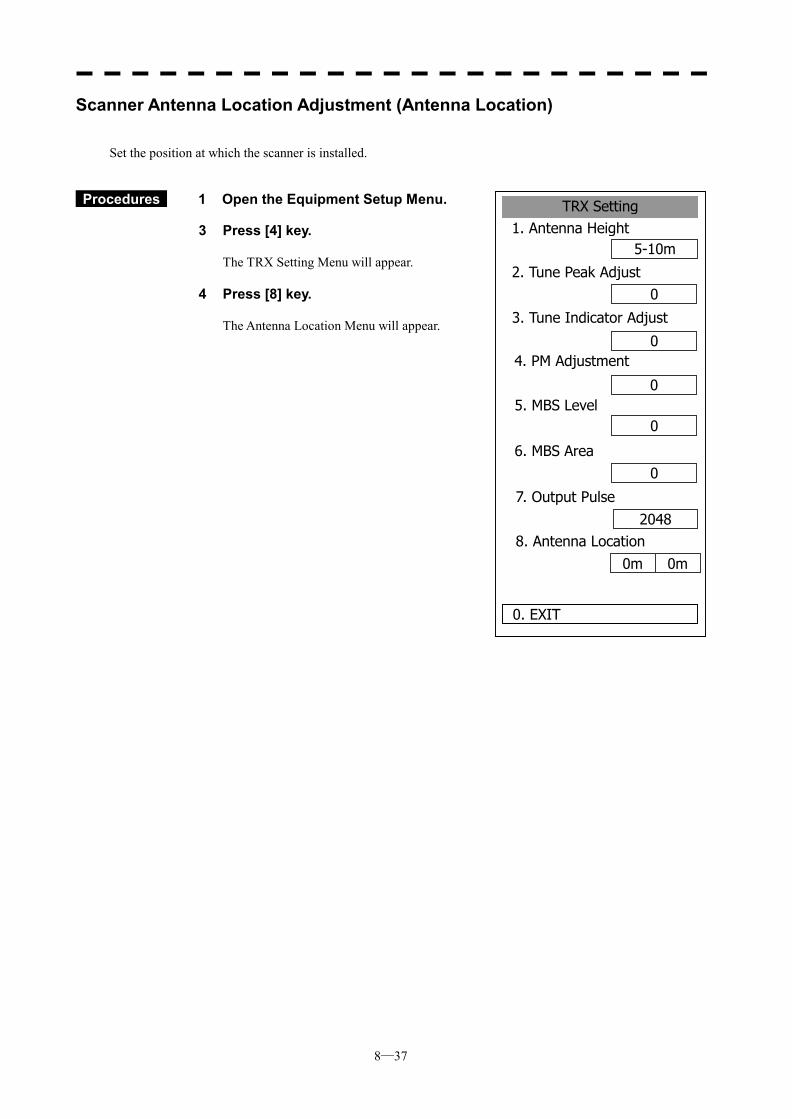
8─37
TRX Setting1. Antenna Height
5-10m
2. Tune Peak Adjust0
0
0. EXIT
3. Tune Indicator Adjust
0
4. PM Adjustment
5. MBS Level
6. MBS Area0
7. Output Pulse2048
8. Antenna Location0m 0m
0
Scanner Antenna Location Adjustment (Antenna Location)
Set the position at which the scanner is installed.
Procedures 1 Open the Equipment Setup Menu.
3 Press [4] key.
The TRX Setting Menu will appear. 4 Press [8] key.
The Antenna Location Menu will appear.
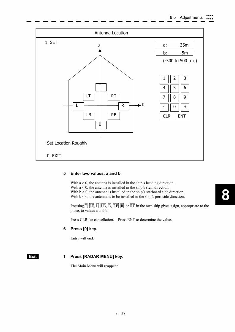
8─38
8.5 Adjustments ����
����
8
5 Enter two values, a and b.
With a > 0, the antenna is installed in the ship’s heading direction. With a < 0, the antenna is installed in the ship’s stem direction. With b > 0, the antenna is installed in the ship’s starboard side direction. With b < 0, the antenna is to be installed in the ship’s port side direction. Pressing T, LT, L, LB, B, RB, R, or RT in the own ship gives �sign, appropriate to the place, to values a and b. Press CLR for cancellation. Press ENT to determine the value.
6 Press [0] key.
Entry will end.
Exit 1 Press [RADAR MENU] key.
The Main Menu will reappear.
b
a a: 35m
b: -5m
4 5 6
1 2 3
7 8 9
- 0 +
CLR ENT
(-500 to 500 [m])
Antenna Location
1. SET
0. EXIT
Set Location Roughly
T
LT
L
LB
B
RT
R
RB
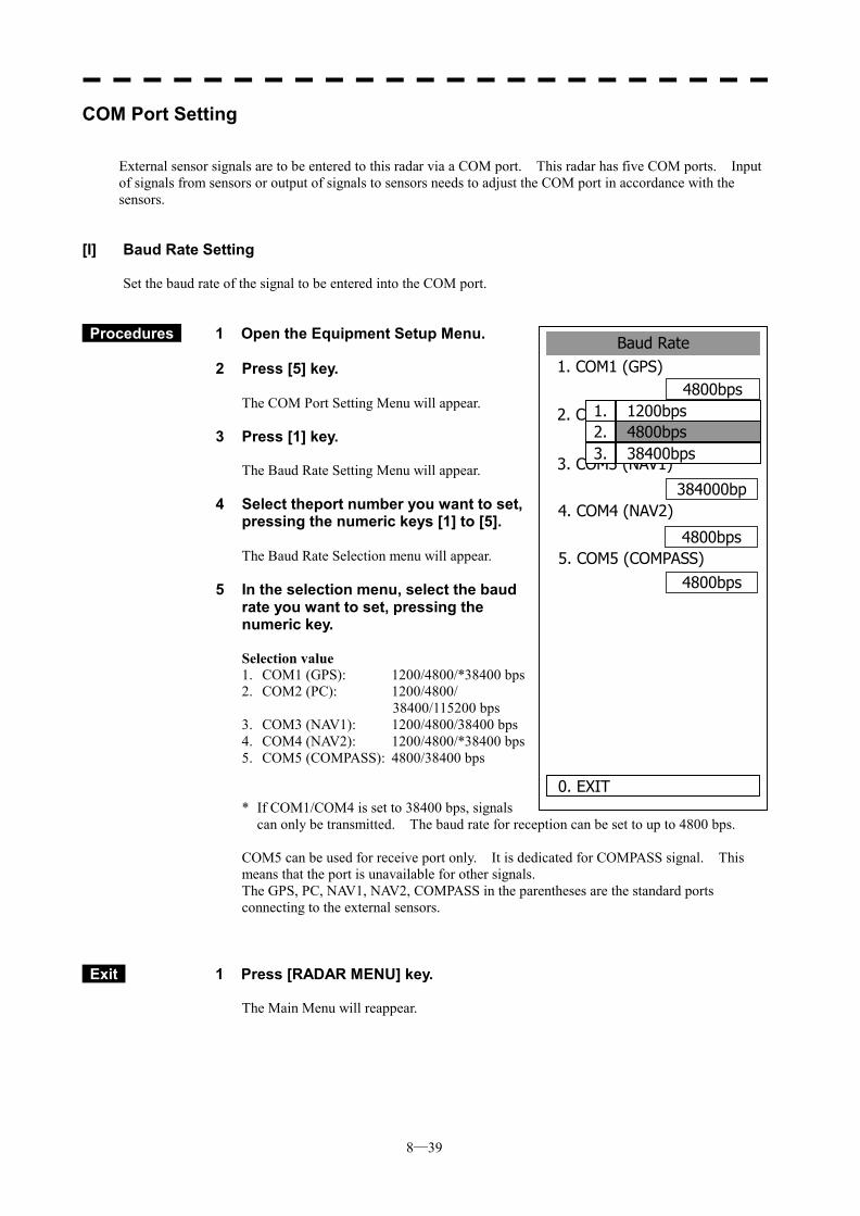
8─39
Baud Rate1. COM1 (GPS)
4800bps
2. COM2 (PC)4800bps
384000bp
0. EXIT
3. COM3 (NAV1)
4800bps
4. COM4 (NAV2)
5. COM5 (COMPASS)4800bps
1. 1200bps2. 4800bps3. 38400bps
COM Port Setting
External sensor signals are to be entered to this radar via a COM port. This radar has five COM ports. Input of signals from sensors or output of signals to sensors needs to adjust the COM port in accordance with the sensors.
[I] Baud Rate Setting
Set the baud rate of the signal to be entered into the COM port.
Procedures 1 Open the Equipment Setup Menu. 2 Press [5] key.
The COM Port Setting Menu will appear.
3 Press [1] key. The Baud Rate Setting Menu will appear.
4 Select theport number you want to set, pressing the numeric keys [1] to [5].
The Baud Rate Selection menu will appear.
5 In the selection menu, select the baud rate you want to set, pressing the numeric key. Selection value 1. COM1 (GPS): 1200/4800/*38400 bps 2. COM2 (PC): 1200/4800/
38400/115200 bps 3. COM3 (NAV1): 1200/4800/38400 bps 4. COM4 (NAV2): 1200/4800/*38400 bps 5. COM5 (COMPASS): 4800/38400 bps * If COM1/COM4 is set to 38400 bps, signals
can only be transmitted. The baud rate for reception can be set to up to 4800 bps. COM5 can be used for receive port only. It is dedicated for COMPASS signal. This means that the port is unavailable for other signals. The GPS, PC, NAV1, NAV2, COMPASS in the parentheses are the standard ports connecting to the external sensors.
Exit 1 Press [RADAR MENU] key. The Main Menu will reappear.
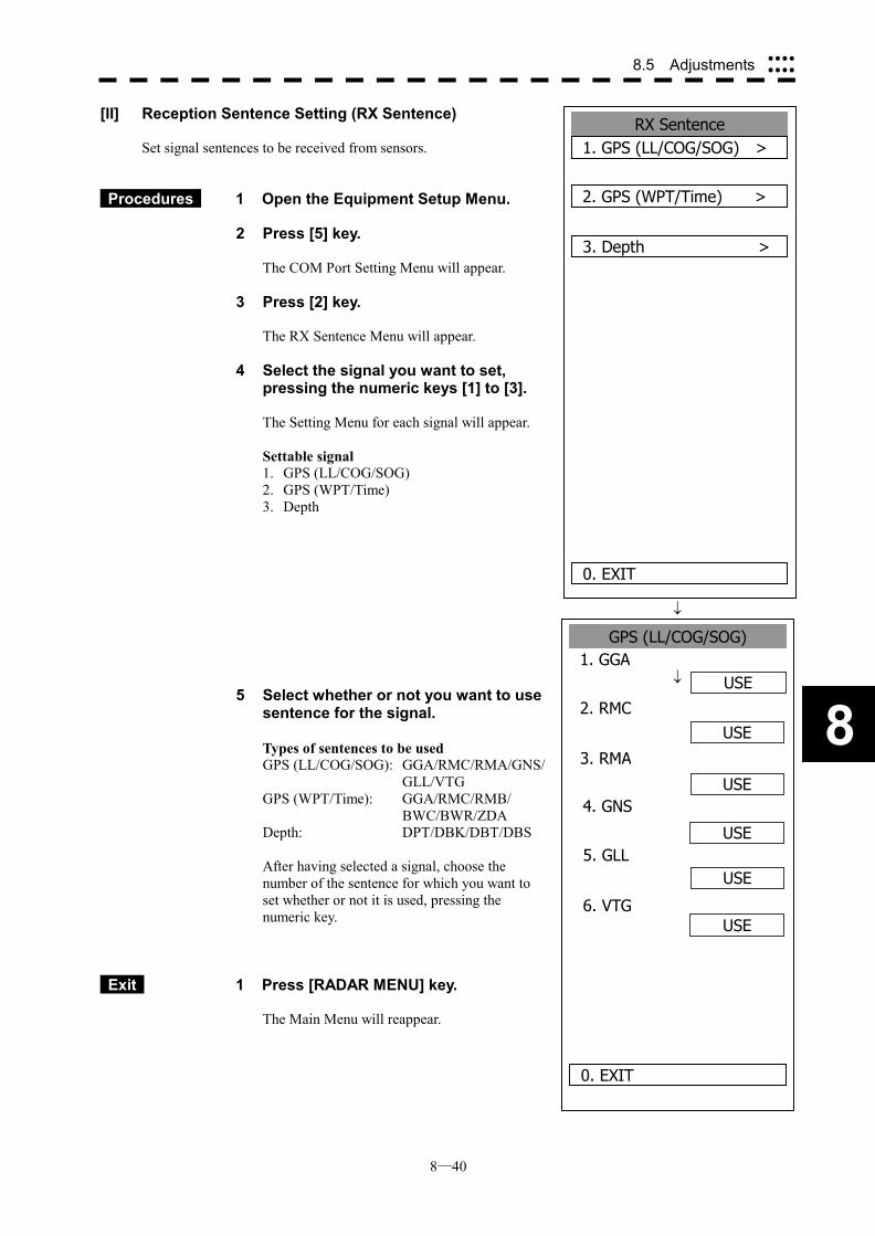
8─40
8.5 Adjustments ����
����
8
RX Sentence 1. GPS (LL/COG/SOG) >
2. GPS (WPT/Time) >
0. EXIT
3. Depth >
GPS (LL/COG/SOG) 1. GGA
USE
2. RMCUSE
USE
0. EXIT
3. RMA
USE
4. GNS
5. GLL
6. VTG
USE
USE
[II] Reception Sentence Setting (RX Sentence) Set signal sentences to be received from sensors.
Procedures 1 Open the Equipment Setup Menu.
2 Press [5] key. The COM Port Setting Menu will appear.
3 Press [2] key. The RX Sentence Menu will appear.
4 Select the signal you want to set, pressing the numeric keys [1] to [3]. The Setting Menu for each signal will appear. Settable signal 1. GPS (LL/COG/SOG) 2. GPS (WPT/Time) 3. Depth
�
� 5 Select whether or not you want to use
sentence for the signal.
Types of sentences to be used GPS (LL/COG/SOG): GGA/RMC/RMA/GNS/
GLL/VTG GPS (WPT/Time): GGA/RMC/RMB/
BWC/BWR/ZDA Depth: DPT/DBK/DBT/DBS After having selected a signal, choose the number of the sentence for which you want to set whether or not it is used, pressing the numeric key.
Exit 1 Press [RADAR MENU] key. The Main Menu will reappear.
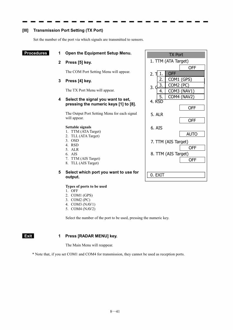
8─41
[III] Transmission Port Setting (TX Port) Set the number of the port via which signals are transmitted to sensors.
Procedures 1 Open the Equipment Setup Menu.
2 Press [5] key.
The COM Port Setting Menu will appear.
3 Press [4] key.
The TX Port Menu will appear.
4 Select the signal you want to set, pressing the numeric keys [1] to [8].
The Output Port Setting Menu for each signal will appear. Settable signals 1. TTM (ATA Target) 2. TLL (ATA Target) 3. OSD 4. RSD 5. ALR 6. AIS 7. TTM (AIS Target) 8. TLL (AIS Target)
5 Select which port you want to use for output.
Types of ports to be used 1. OFF 2. COM1 (GPS) 3. COM2 (PC) 4. COM3 (NAV1) 5. COM4 (NAV2) Select the number of the port to be used, pressing the numeric key.
Exit 1 Press [RADAR MENU] key. The Main Menu will reappear.
* Note that, if you set COM1 and COM4 for transmission, they cannot be used as reception ports.
TX Port1. TTM (ATA Target)
2. TLL(ATA Target)
0. EXIT
3. OSD
OFF
OFF
OFF
OFF
OFF
AUTO
4. RSD
5. ALR
6. AIS
OFF7. TTM (AIS Target)
OFF8. TTM (AIS Target)
1. OFF2. COM1 (GPS)3. COM2 (PC)4. COM3 (NAV1)5. COM4 (NAV2)
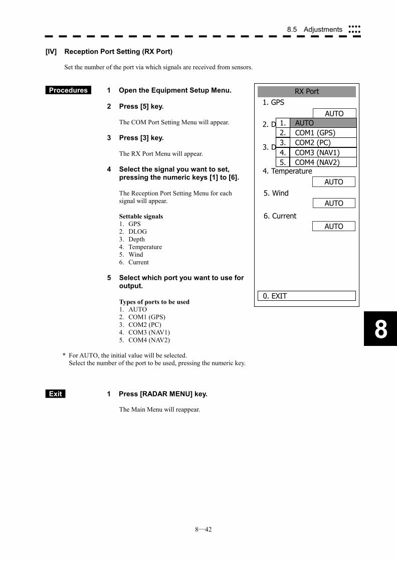
8─42
8.5 Adjustments ����
����
8
RX Port1. GPS
2. DLOG
0. EXIT
3. Depth
AUTO
AUTO
OFF
AUTO
AUTO
AUTO
4. Temperature
5. Wind
6. Current
1. AUTO2. COM1 (GPS)3. COM2 (PC)4. COM3 (NAV1)5. COM4 (NAV2)
[IV] Reception Port Setting (RX Port) Set the number of the port via which signals are received from sensors.
Procedures 1 Open the Equipment Setup Menu. 2 Press [5] key.
The COM Port Setting Menu will appear.
3 Press [3] key.
The RX Port Menu will appear.
4 Select the signal you want to set, pressing the numeric keys [1] to [6].
The Reception Port Setting Menu for each signal will appear. Settable signals 1. GPS 2. DLOG 3. Depth 4. Temperature 5. Wind 6. Current
5 Select which port you want to use for output.
Types of ports to be used 1. AUTO 2. COM1 (GPS) 3. COM2 (PC) 4. COM3 (NAV1) 5. COM4 (NAV2)
* For AUTO, the initial value will be selected. Select the number of the port to be used, pressing the numeric key.
Exit 1 Press [RADAR MENU] key. The Main Menu will reappear.
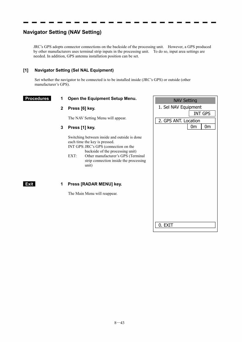
8─43
NAV Setting1. Sel NAV Equipment
INT GPS
2. GPS ANT. Location
0. EXIT
0m 0m
Navigator Setting (NAV Setting)
JRC’s GPS adopts connector connections on the backside of the processing unit. However, a GPS produced by other manufacturers uses terminal strip inputs in the processing unit. To do so, input area settings are needed. In addition, GPS antenna installation position can be set.
[1] Navigator Setting (Sel NAL Equipment) Set whether the navigator to be connected is to be installed inside (JRC’s GPS) or outside (other manufacturer’s GPS).
Procedures 1 Open the Equipment Setup Menu. 2 Press [6] key.
The NAV Setting Menu will appear.
3 Press [1] key.
Switching between inside and outside is done each time the key is pressed. INT GPS: JRC’s GPS (connection on the
backside of the processing unit) EXT: Other manufacturer’s GPS (Terminal
strip connection inside the processing unit)
Exit 1 Press [RADAR MENU] key. The Main Menu will reappear.
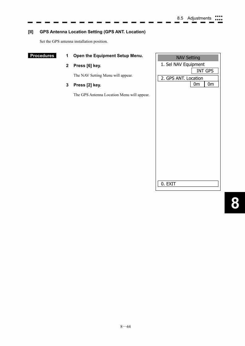
8─44
8.5 Adjustments ����
����
8
NAV Setting1. Sel NAV Equipment
INT GPS
2. GPS ANT. Location
0. EXIT
0m 0m
[II] GPS Antenna Location Setting (GPS ANT. Location) Set the GPS antenna installation position.
Procedures 1 Open the Equipment Setup Menu. 2 Press [6] key.
The NAV Setting Menu will appear.
3 Press [2] key.
The GPS Antenna Location Menu will appear.
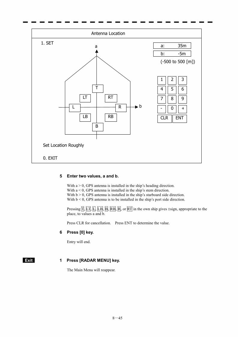
8─45
5 Enter two values, a and b.
With a > 0, GPS antenna is installed in the ship’s heading direction. With a < 0, GPS antenna is installed in the ship’s stem direction. With b > 0, GPS antenna is installed in the ship’s starboard side direction. With b < 0, GPS antenna is to be installed in the ship’s port side direction. Pressing T, LT, L, LB, B, RB, R, or RT in the own ship gives �sign, appropriate to the place, to values a and b. Press CLR for cancellation. Press ENT to determine the value.
6 Press [0] key.
Entry will end.
Exit 1 Press [RADAR MENU] key.
The Main Menu will reappear.
b
a a: 35m
b: -5m
4 5 6
1 2 3
7 8 9
- 0 +
CLR ENT
(-500 to 500 [m])
Antenna Location
1. SET
0. EXIT
Set Location Roughly
T
LT
L
LB
B
RT
R
RB
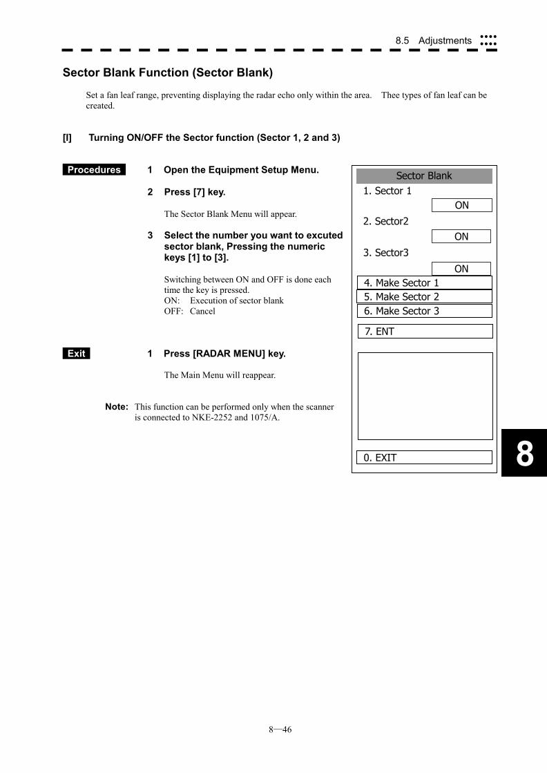
8─46
8.5 Adjustments ����
����
8
Sector Blank1. Sector 1
ON
2. Sector2ON
ON
0. EXIT
3. Sector3
4. Make Sector 15. Make Sector 26. Make Sector 3
7. ENT
Sector Blank Function (Sector Blank)
Set a fan leaf range, preventing displaying the radar echo only within the area. Thee types of fan leaf can be created.
[I] Turning ON/OFF the Sector function (Sector 1, 2 and 3)
Procedures 1 Open the Equipment Setup Menu. 2 Press [7] key.
The Sector Blank Menu will appear.
3 Select the number you want to excuted sector blank, Pressing the numeric keys [1] to [3].
Switching between ON and OFF is done each time the key is pressed. ON: Execution of sector blank OFF: Cancel
Exit 1 Press [RADAR MENU] key. The Main Menu will reappear.
Note: This function can be performed only when the scanner is connected to NKE-2252 and 1075/A.
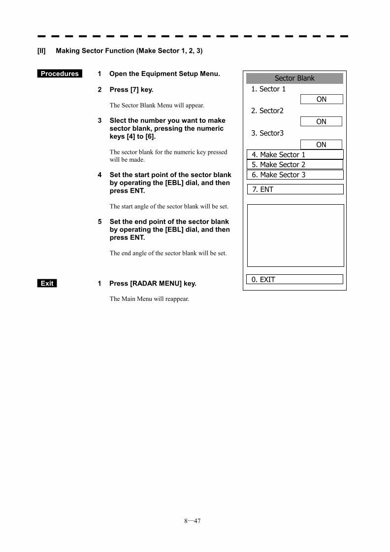
8─47
Sector Blank1. Sector 1
ON
2. Sector2ON
ON
0. EXIT
3. Sector3
4. Make Sector 15. Make Sector 26. Make Sector 3
7. ENT
[II] Making Sector Function (Make Sector 1, 2, 3)
Procedures 1 Open the Equipment Setup Menu. 2 Press [7] key.
The Sector Blank Menu will appear.
3 Slect the number you want to make sector blank, pressing the numeric keys [4] to [6].
The sector blank for the numeric key pressed will be made.
4 Set the start point of the sector blank by operating the [EBL] dial, and then press ENT.
The start angle of the sector blank will be set.
5 Set the end point of the sector blank by operating the [EBL] dial, and then press ENT.
The end angle of the sector blank will be set.
Exit 1 Press [RADAR MENU] key. The Main Menu will reappear.
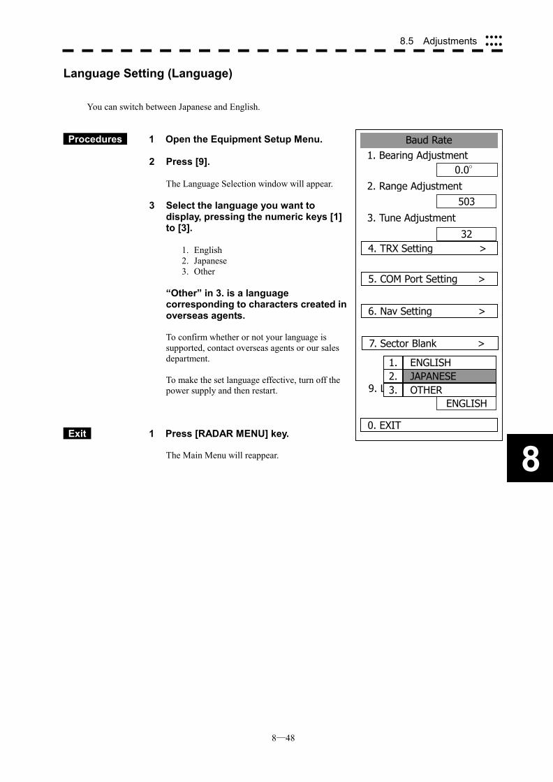
8─48
8.5 Adjustments ����
����
8
Baud Rate1. Bearing Adjustment
0.0°
2. Range Adjustment503
32
0. EXIT
3. Tune Adjustment
4. TRX Setting >
5. COM Port Setting >
ENGLISH
6. Nav Setting >
7. Sector Blank >
9. Language
1. ENGLISH2. JAPANESE3. OTHER
Language Setting (Language)
You can switch between Japanese and English.
Procedures 1 Open the Equipment Setup Menu. 2 Press [9].
The Language Selection window will appear.
3 Select the language you want to display, pressing the numeric keys [1] to [3].
1. English 2. Japanese 3. Other
“Other” in 3. is a language
corresponding to characters created in overseas agents. To confirm whether or not your language is supported, contact overseas agents or our sales department. To make the set language effective, turn off the power supply and then restart.
Exit 1 Press [RADAR MENU] key. The Main Menu will reappear.
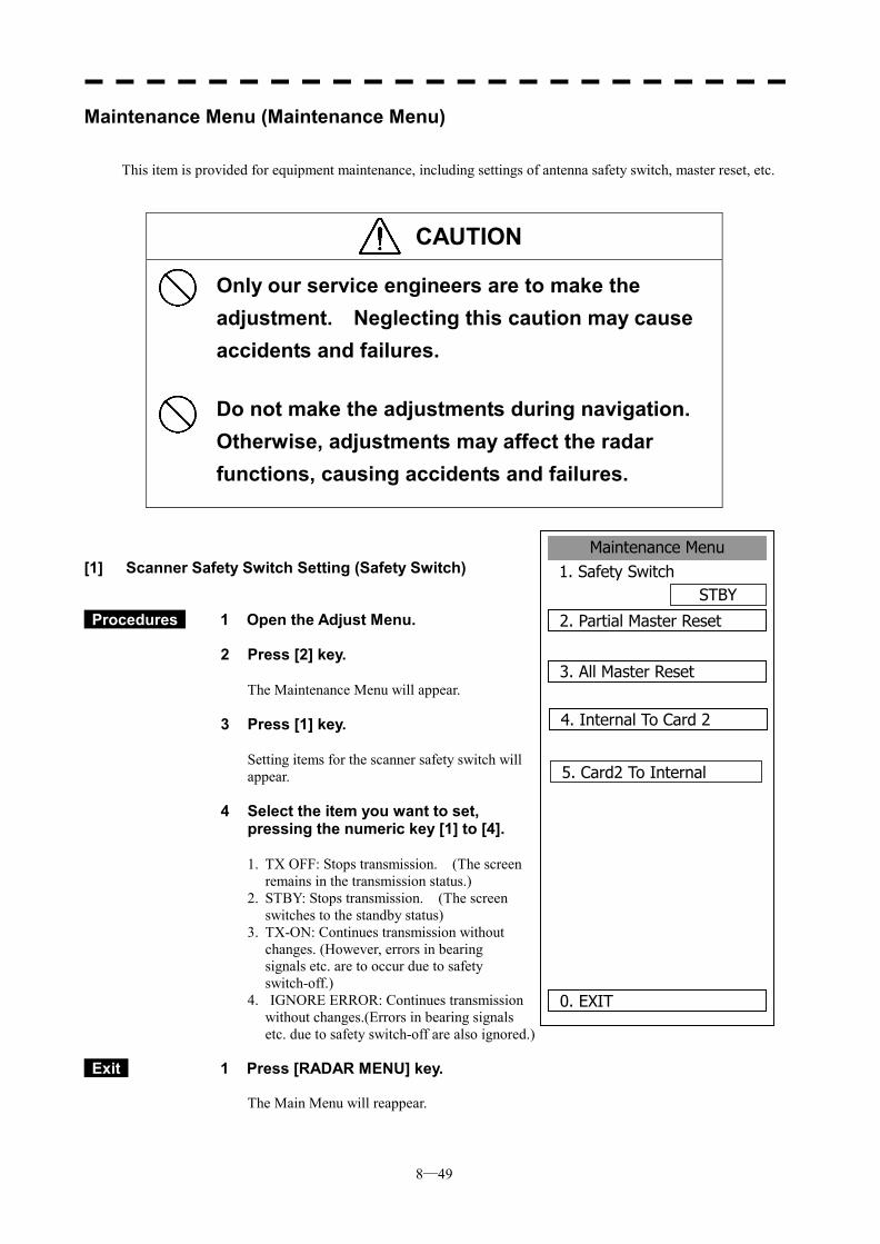
8─49
Maintenance Menu1. Safety Switch
STBY
2. Partial Master Reset
0. EXIT
3. All Master Reset
4. Internal To Card 2
5. Card2 To Internal
Maintenance Menu (Maintenance Menu)
This item is provided for equipment maintenance, including settings of antenna safety switch, master reset, etc.
CAUTION
Only our service engineers are to make the adjustment. Neglecting this caution may cause accidents and failures.
Do not make the adjustments during navigation. Otherwise, adjustments may affect the radar functions, causing accidents and failures.
[1] Scanner Safety Switch Setting (Safety Switch)
Procedures 1 Open the Adjust Menu.
2 Press [2] key.
The Maintenance Menu will appear.
3 Press [1] key.
Setting items for the scanner safety switch will appear.
4 Select the item you want to set, pressing the numeric key [1] to [4].
1. TX OFF: Stops transmission. (The screen
remains in the transmission status.) 2. STBY: Stops transmission. (The screen
switches to the standby status) 3. TX-ON: Continues transmission without
changes. (However, errors in bearing signals etc. are to occur due to safety switch-off.)
4. IGNORE ERROR: Continues transmission without changes.(Errors in bearing signals etc. due to safety switch-off are also ignored.)
Exit 1 Press [RADAR MENU] key.
The Main Menu will reappear.
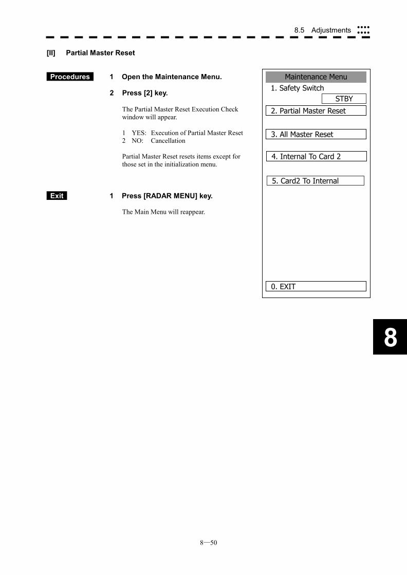
8─50
8.5 Adjustments ����
����
8
Maintenance Menu1. Safety Switch
STBY
2. Partial Master Reset
0. EXIT
3. All Master Reset
4. Internal To Card 2
5. Card2 To Internal
[II] Partial Master Reset
Procedures 1 Open the Maintenance Menu.
2 Press [2] key.
The Partial Master Reset Execution Check window will appear. 1 YES: Execution of Partial Master Reset 2 NO: Cancellation Partial Master Reset resets items except for those set in the initialization menu.
Exit 1 Press [RADAR MENU] key. The Main Menu will reappear.
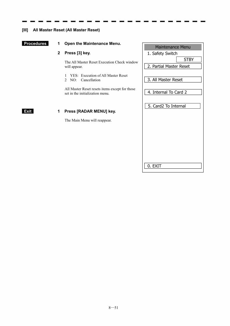
8─51
Maintenance Menu1. Safety Switch
STBY
2. Partial Master Reset
0. EXIT
3. All Master Reset
4. Internal To Card 2
5. Card2 To Internal
[III] All Master Reset (All Master Reset)
Procedures 1 Open the Maintenance Menu. 2 Press [3] key.
The All Master Reset Execution Check window will appear. 1 YES: Execution of All Master Reset 2 NO: Cancellation All Master Reset resets items except for those set in the initialization menu.
Exit 1 Press [RADAR MENU] key. The Main Menu will reappear.
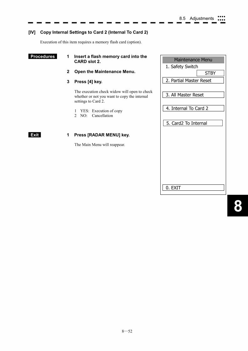
8─52
8.5 Adjustments ����
����
8
Maintenance Menu1. Safety Switch
STBY
2. Partial Master Reset
0. EXIT
3. All Master Reset
4. Internal To Card 2
5. Card2 To Internal
[IV] Copy Internal Settings to Card 2 (Internal To Card 2)
Execution of this item requires a memory flash card (option).
Procedures 1 Insert a flash memory card into the CARD slot 2.
2 Open the Maintenance Menu. 3 Press [4] key.
The execution check widow will open to check whether or not you want to copy the internal settings to Card 2. 1 YES: Execution of copy 2 NO: Cancellation
Exit 1 Press [RADAR MENU] key. The Main Menu will reappear.
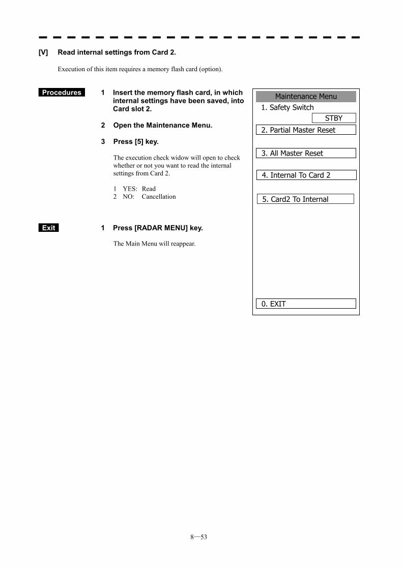
8─53
Maintenance Menu1. Safety Switch
STBY
2. Partial Master Reset
0. EXIT
3. All Master Reset
4. Internal To Card 2
5. Card2 To Internal
[V] Read internal settings from Card 2.
Execution of this item requires a memory flash card (option).
Procedures 1 Insert the memory flash card, in which internal settings have been saved, into Card slot 2.
2 Open the Maintenance Menu. 3 Press [5] key.
The execution check widow will open to check whether or not you want to read the internal settings from Card 2. 1 YES: Read 2 NO: Cancellation
Exit 1 Press [RADAR MENU] key. The Main Menu will reappear.
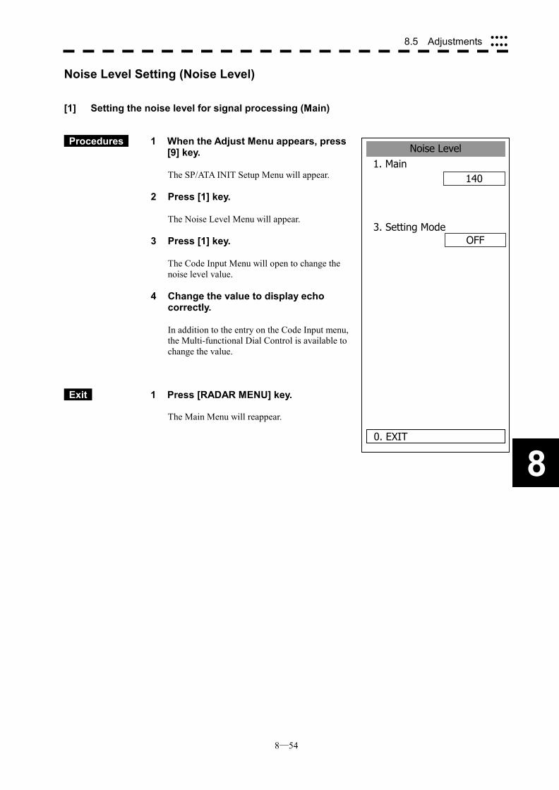
8─54
8.5 Adjustments ����
����
8
Noise Level1. Main
140
0. EXIT
3. Setting Mode
OFF
Noise Level Setting (Noise Level)
[1] Setting the noise level for signal processing (Main)
Procedures 1 When the Adjust Menu appears, press [9] key.
The SP/ATA INIT Setup Menu will appear.
2 Press [1] key.
The Noise Level Menu will appear.
3 Press [1] key.
The Code Input Menu will open to change the noise level value.
4 Change the value to display echo correctly.
In addition to the entry on the Code Input menu, the Multi-functional Dial Control is available to change the value.
Exit 1 Press [RADAR MENU] key. The Main Menu will reappear.
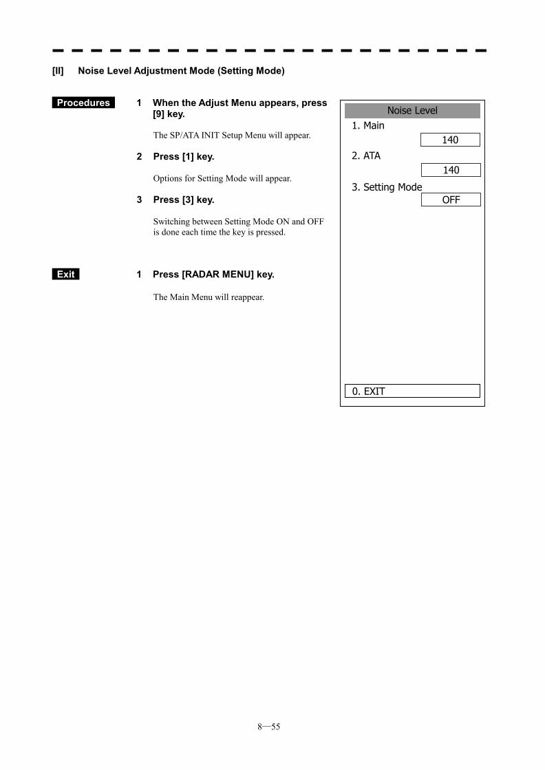
8─55
Noise Level1. Main
140
2. ATA
0. EXIT
3. Setting Mode
140
OFF
[II] Noise Level Adjustment Mode (Setting Mode)
Procedures 1 When the Adjust Menu appears, press [9] key. The SP/ATA INIT Setup Menu will appear.
2 Press [1] key.
Options for Setting Mode will appear.
3 Press [3] key.
Switching between Setting Mode ON and OFF is done each time the key is pressed.
Exit 1 Press [RADAR MENU] key.
The Main Menu will reappear.
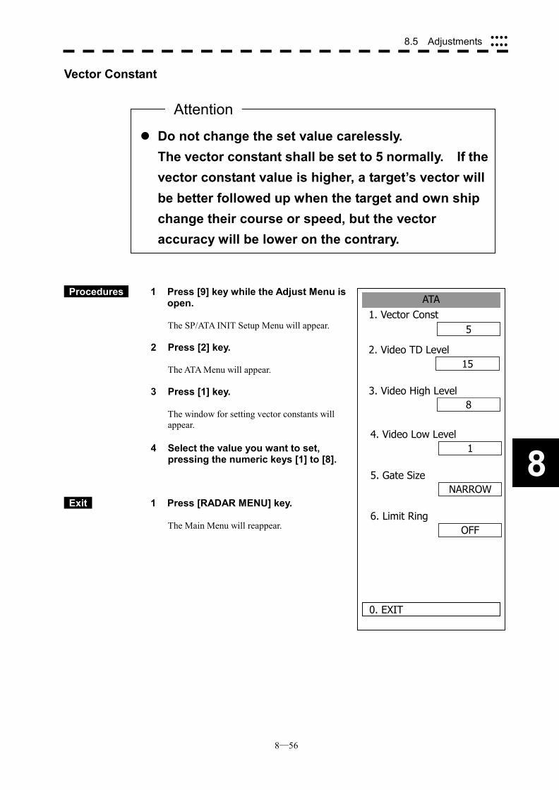
8─56
8.5 Adjustments ����
����
8
ATA1. Vector Const
5
2. Video TD Level15
8
0. EXIT
3. Video High Level
14. Video Low Level
NARROW5. Gate Size
OFF6. Limit Ring
Vector Constant
Procedures 1 Press [9] key while the Adjust Menu is open.
The SP/ATA INIT Setup Menu will appear.
2 Press [2] key.
The ATA Menu will appear.
3 Press [1] key.
The window for setting vector constants will appear.
4 Select the value you want to set, pressing the numeric keys [1] to [8].
Exit 1 Press [RADAR MENU] key.
The Main Menu will reappear.
��Do not change the set value carelessly. The vector constant shall be set to 5 normally. If thevector constant value is higher, a target’s vector will be better followed up when the target and own ship change their course or speed, but the vector accuracy will be lower on the contrary.
Attention
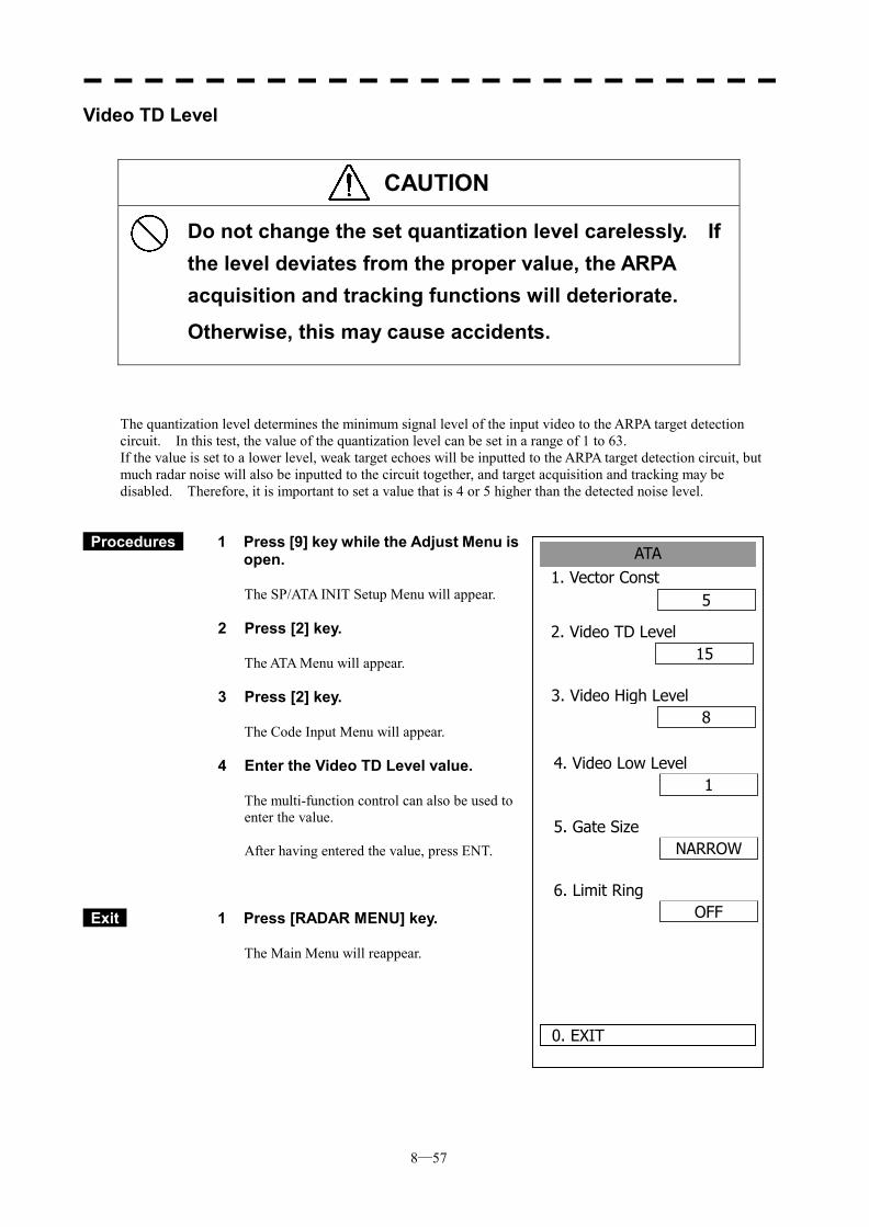
8─57
ATA1. Vector Const
5
2. Video TD Level15
8
0. EXIT
3. Video High Level
14. Video Low Level
NARROW5. Gate Size
OFF6. Limit Ring
Video TD Level
CAUTION
Do not change the set quantization level carelessly. If the level deviates from the proper value, the ARPA acquisition and tracking functions will deteriorate. Otherwise, this may cause accidents.
The quantization level determines the minimum signal level of the input video to the ARPA target detection circuit. In this test, the value of the quantization level can be set in a range of 1 to 63. If the value is set to a lower level, weak target echoes will be inputted to the ARPA target detection circuit, but much radar noise will also be inputted to the circuit together, and target acquisition and tracking may be disabled. Therefore, it is important to set a value that is 4 or 5 higher than the detected noise level.
Procedures 1 Press [9] key while the Adjust Menu is open.
The SP/ATA INIT Setup Menu will appear.
2 Press [2] key.
The ATA Menu will appear.
3 Press [2] key.
The Code Input Menu will appear.
4 Enter the Video TD Level value.
The multi-function control can also be used to enter the value. After having entered the value, press ENT.
Exit 1 Press [RADAR MENU] key.
The Main Menu will reappear.
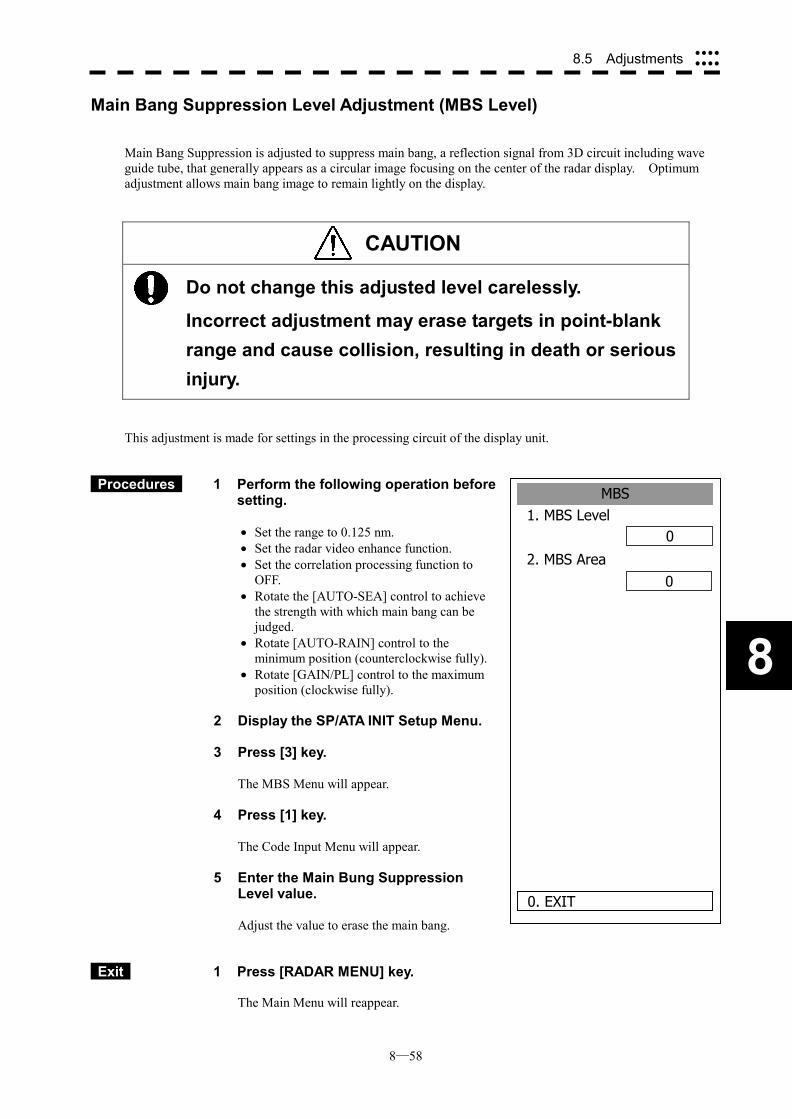
8─58
8.5 Adjustments ����
����
8
MBS1. MBS Level
0
2. MBS Area0
0. EXIT
Main Bang Suppression Level Adjustment (MBS Level)
Main Bang Suppression is adjusted to suppress main bang, a reflection signal from 3D circuit including wave guide tube, that generally appears as a circular image focusing on the center of the radar display. Optimum adjustment allows main bang image to remain lightly on the display.
CAUTION
Do not change this adjusted level carelessly.
Incorrect adjustment may erase targets in point-blank range and cause collision, resulting in death or serious injury.
This adjustment is made for settings in the processing circuit of the display unit.
Procedures 1 Perform the following operation before setting. �� Set the range to 0.125 nm. �� Set the radar video enhance function. �� Set the correlation processing function to
OFF. �� Rotate the [AUTO-SEA] control to achieve
the strength with which main bang can be judged.
�� Rotate [AUTO-RAIN] control to the minimum position (counterclockwise fully).
�� Rotate [GAIN/PL] control to the maximum position (clockwise fully).
2 Display the SP/ATA INIT Setup Menu.
3 Press [3] key.
The MBS Menu will appear.
4 Press [1] key.
The Code Input Menu will appear.
5 Enter the Main Bung Suppression Level value.
Adjust the value to erase the main bang.
Exit 1 Press [RADAR MENU] key. The Main Menu will reappear.
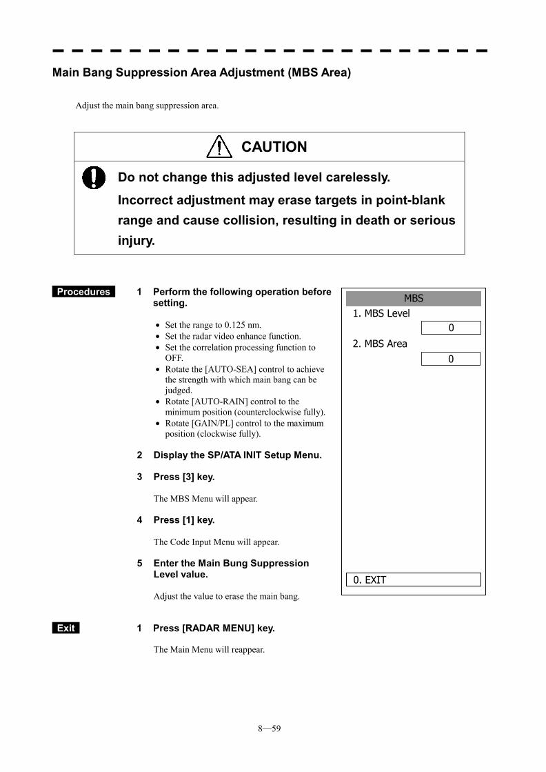
8─59
MBS1. MBS Level
0
2. MBS Area0
0. EXIT
Main Bang Suppression Area Adjustment (MBS Area)
Adjust the main bang suppression area.
CAUTION
Do not change this adjusted level carelessly. Incorrect adjustment may erase targets in point-blank range and cause collision, resulting in death or serious injury.
Procedures 1 Perform the following operation before setting. �� Set the range to 0.125 nm. �� Set the radar video enhance function. �� Set the correlation processing function to
OFF. �� Rotate the [AUTO-SEA] control to achieve
the strength with which main bang can be judged.
�� Rotate [AUTO-RAIN] control to the minimum position (counterclockwise fully).
�� Rotate [GAIN/PL] control to the maximum position (clockwise fully).
2 Display the SP/ATA INIT Setup Menu.
3 Press [3] key.
The MBS Menu will appear.
4 Press [1] key.
The Code Input Menu will appear.
5 Enter the Main Bung Suppression Level value.
Adjust the value to erase the main bang.
Exit 1 Press [RADAR MENU] key. The Main Menu will reappear.
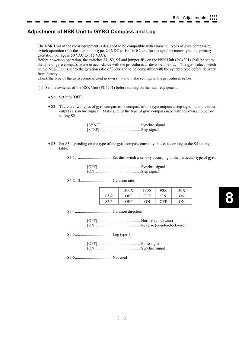
8─60
8.5 Adjustments ����
����
8
Adjustment of NSK Unit to GYRO Compass and Log
The NSK Unit of the radar equipment is designed to be compatible with almost all types of gyro compass by switch operation (For the step motor type, 24 VDC to 100 VDC, and for the synchro-motor type, the primary excitation voltage is 50 VAC to 115 VAC). Before power-on operation, the switches S1, S2, S5 and jumper JP1 on the NSK Unit (PC4201) shall be set to the type of gyro compass in use in accordance with the procedures as described below. The gyro select switch on the NSK Unit is set to the gyration ratio of 360X and to be compatible with the synchro type before delivery from factory. Check the type of the gyro compass used in own ship and make settings in the procedures below.
(1) Set the switches of the NSK Unit (PC4201) before turning on the radar equipment.
� S1: Set it to [OFF]. � S2: There are two types of gyro compasses: a compass of one type outputs a step signal, and the other
outputs a synchro signal. Make sure of the type of gyro compass used with the own ship before setting S2.
[SYNC] .......................................Synchro signal [STEP].........................................Step signal
� S5: Set S5 depending on the type of the gyro compass currently in use, according to the S5 setting
table.
S5-1: ..................................Set this switch assembly according to the particular type of gyro.
[OFF]...........................................Synchro signal [ON] ............................................Step signal
S5-2, -3................................Gyration ratio
360X 180X 90X 36X S5-2 OFF OFF ON ON S5-3 OFF ON OFF ON
S5-4.....................................Gyration direction
[OFF]...........................................Normal (clockwise) [ON] ............................................Reverse (counterclockwise)
S5-5.....................................Log type-1
[OFF]...........................................Pulse signal [ON] ............................................Synchro signal
S5-6.....................................Not used
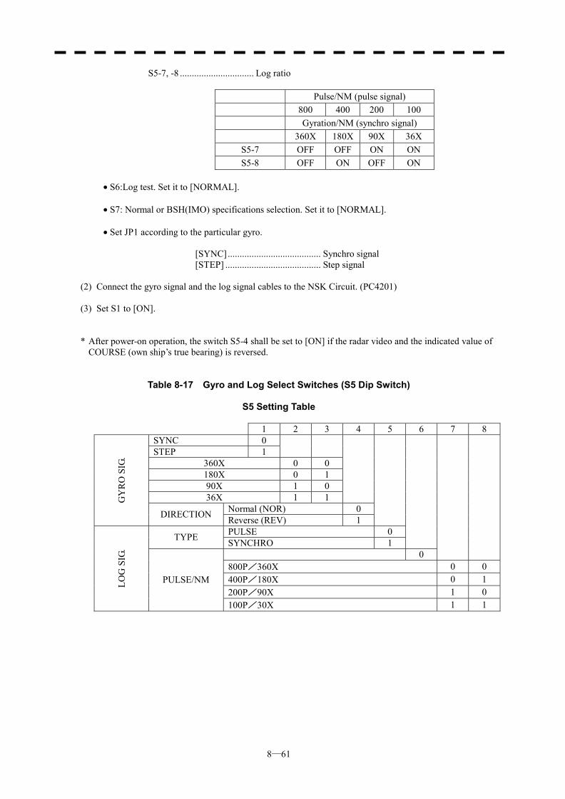
8─61
S5-7, -8 ............................... Log ratio
Pulse/NM (pulse signal) 800 400 200 100 Gyration/NM (synchro signal) 360X 180X 90X 36X
S5-7 OFF OFF ON ON S5-8 OFF ON OFF ON
� S6:Log test. Set it to [NORMAL]. � S7: Normal or BSH(IMO) specifications selection. Set it to [NORMAL].
� Set JP1 according to the particular gyro.
[SYNC]....................................... Synchro signal [STEP] ........................................ Step signal
(2) Connect the gyro signal and the log signal cables to the NSK Circuit. (PC4201) (3) Set S1 to [ON].
* After power-on operation, the switch S5-4 shall be set to [ON] if the radar video and the indicated value of COURSE (own ship’s true bearing) is reversed.
Table 8-17 Gyro and Log Select Switches (S5 Dip Switch)
S5 Setting Table
1 2 3 4 5 6 7 8 SYNC 0 STEP 1
360X 0 0 180X 0 1 90X 1 0 36X 1 1
Normal (NOR) 0
GY
RO
SIG
.
DIRECTION Reverse (REV) 1
PULSE 0 TYPE SYNCHRO 1
0
800P/360X 0 0 400P/180X 0 1 200P/90X 1 0
LOG
SIG
.
PULSE/NM
100P/30X 1 1
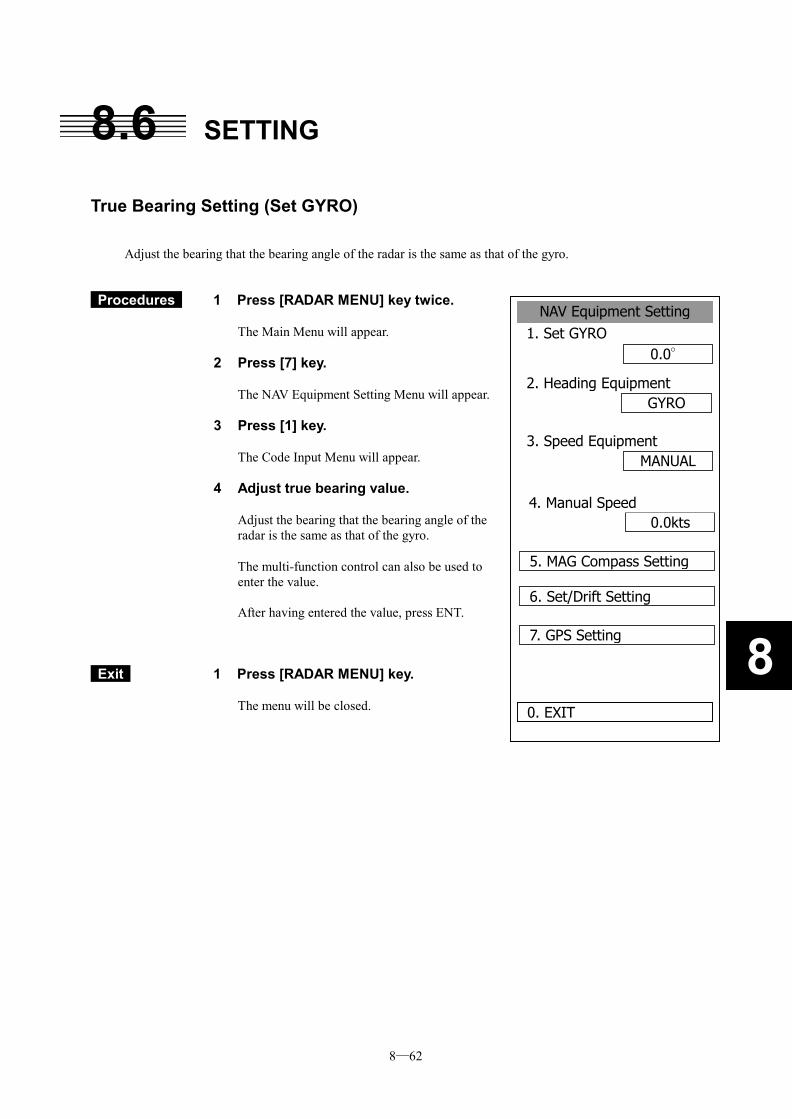
8─62
8
8.6 SETTING
True Bearing Setting (Set GYRO)
Adjust the bearing that the bearing angle of the radar is the same as that of the gyro.
Procedures 1 Press [RADAR MENU] key twice.
The Main Menu will appear.
2 Press [7] key.
The NAV Equipment Setting Menu will appear.
3 Press [1] key.
The Code Input Menu will appear.
4 Adjust true bearing value.
Adjust the bearing that the bearing angle of the radar is the same as that of the gyro.
The multi-function control can also be used to enter the value. After having entered the value, press ENT.
Exit 1 Press [RADAR MENU] key.
The menu will be closed.
NAV Equipment Setting1. Set GYRO
0.0°
2. Heading EquipmentGYRO
MANUAL
0. EXIT
3. Speed Equipment
0.0kts4. Manual Speed
5. MAG Compass Setting
6. Set/Drift Setting
7. GPS Setting
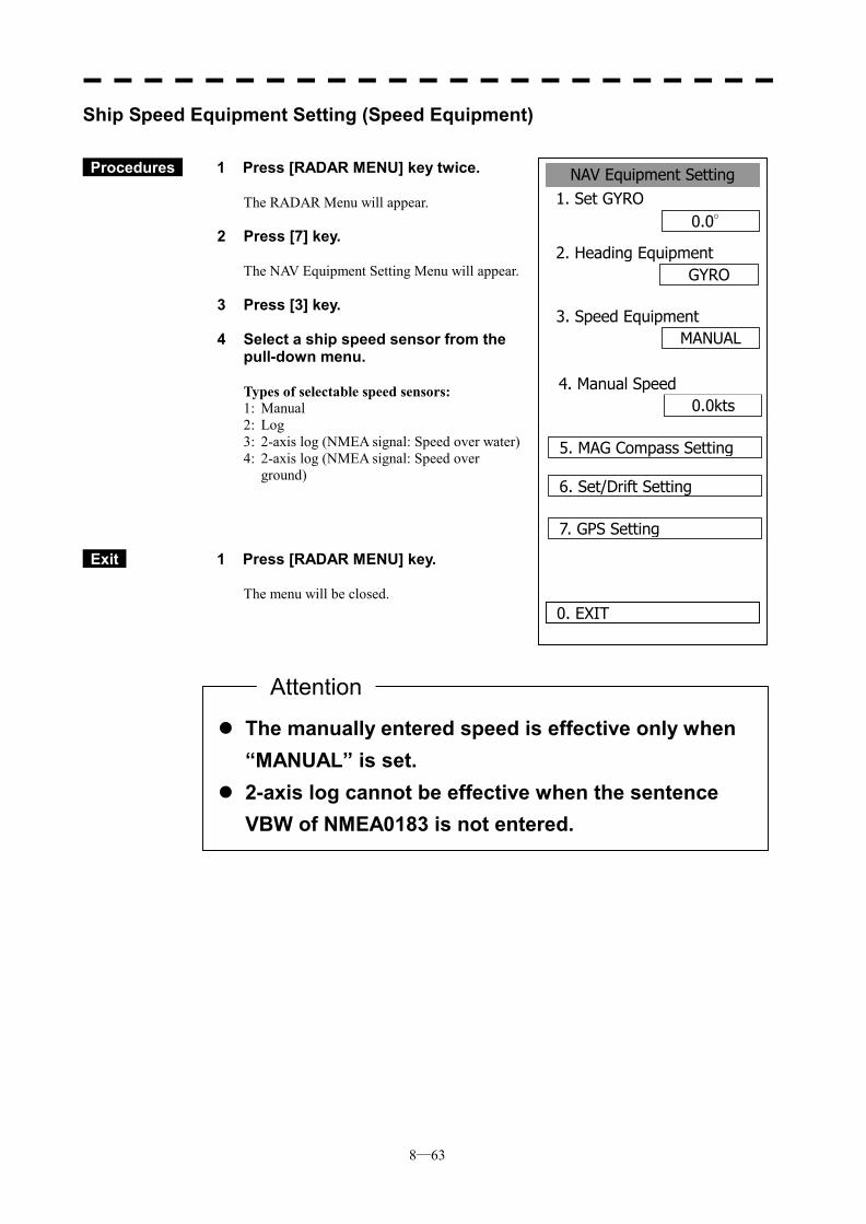
8─63
NAV Equipment Setting1. Set GYRO
0.0°
2. Heading EquipmentGYRO
MANUAL
0. EXIT
3. Speed Equipment
0.0kts4. Manual Speed
5. MAG Compass Setting
6. Set/Drift Setting
7. GPS Setting
Ship Speed Equipment Setting (Speed Equipment)
Procedures 1 Press [RADAR MENU] key twice.
The RADAR Menu will appear.
2 Press [7] key.
The NAV Equipment Setting Menu will appear.
3 Press [3] key.
4 Select a ship speed sensor from the pull-down menu.
Types of selectable speed sensors: 1: Manual 2: Log 3: 2-axis log (NMEA signal: Speed over water) 4: 2-axis log (NMEA signal: Speed over
ground)
Exit 1 Press [RADAR MENU] key.
The menu will be closed.
��The manually entered speed is effective only when “MANUAL” is set.
��2-axis log cannot be effective when the sentence VBW of NMEA0183 is not entered.
Attention
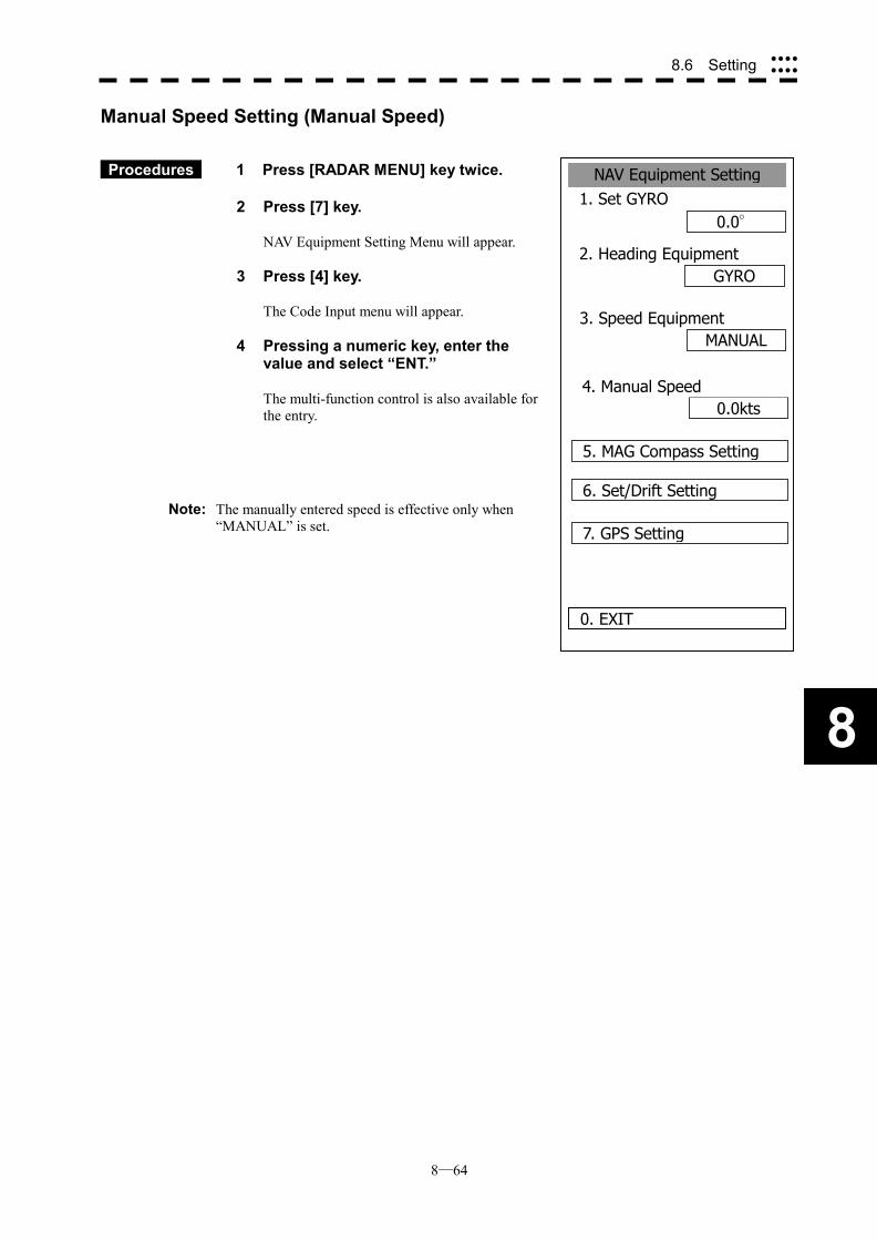
8─64
8
8.6 Setting ����
����
NAV Equipment Setting1. Set GYRO
0.0°
2. Heading EquipmentGYRO
MANUAL
0. EXIT
3. Speed Equipment
0.0kts4. Manual Speed
5. MAG Compass Setting
6. Set/Drift Setting
7. GPS Setting
Manual Speed Setting (Manual Speed)
Procedures 1 Press [RADAR MENU] key twice.
2 Press [7] key.
NAV Equipment Setting Menu will appear.
3 Press [4] key.
The Code Input menu will appear.
4 Pressing a numeric key, enter the value and select “ENT.”
The multi-function control is also available for the entry.
Note: The manually entered speed is effective only when
“MANUAL” is set.
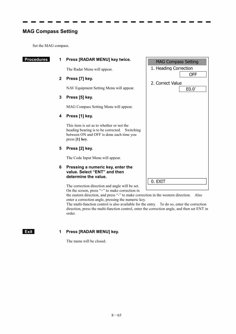
8─65
MAG Compass Setting1. Heading Correction
OFF
2. Correct ValueE0.0°
0. EXIT
MAG Compass Setting
Set the MAG compass.
Procedures 1 Press [RADAR MENU] key twice.
The Radar Menu will appear.
2 Press [7] key.
NAV Equipment Setting Menu will appear.
3 Press [5] key.
MAG Compass Setting Menu will appear.
4 Press [1] key.
This item is set as to whether or not the heading bearing is to be corrected. Switching between ON and OFF is done each time you press [1] key.
5 Press [2] key.
The Code Input Menu will appear.
6 Pressing a numeric key, enter the value. Select “ENT” and then determine the value. The correction direction and angle will be set. On the screen, press “+” to make correction in the eastern direction, and press “-” to make correction in the western direction. Also enter a correction angle, pressing the numeric key. The multi-function control is also available for the entry. To do so, enter the correction direction, press the multi-function control, enter the correction angle, and then set ENT in order.
Exit 1 Press [RADAR MENU] key.
The menu will be closed.
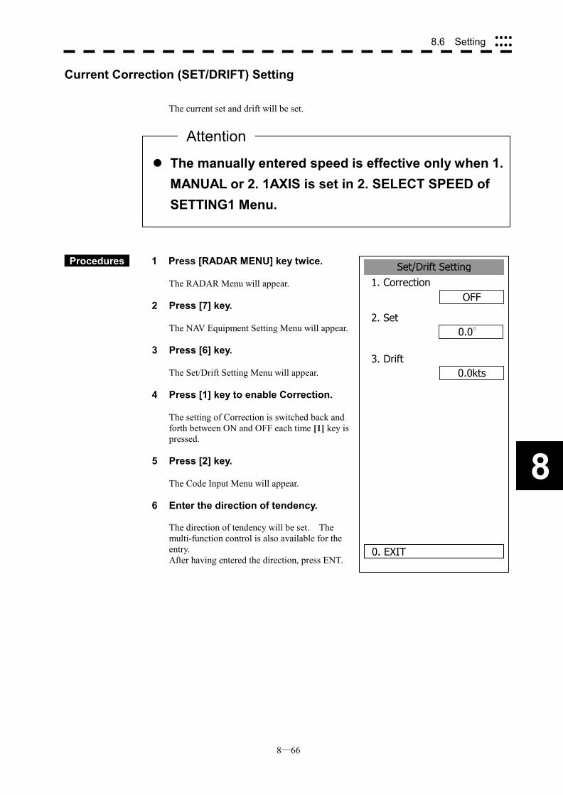
8─66
8
8.6 Setting ����
����
Set/Drift Setting1. Correction
OFF
2. Set 0.0°
0.0kts
0. EXIT
3. Drift
Current Correction (SET/DRIFT) Setting The current set and drift will be set.
Procedures 1 Press [RADAR MENU] key twice.
The RADAR Menu will appear.
2 Press [7] key.
The NAV Equipment Setting Menu will appear.
3 Press [6] key.
The Set/Drift Setting Menu will appear.
4 Press [1] key to enable Correction.
The setting of Correction is switched back and forth between ON and OFF each time [1] key is pressed.
5 Press [2] key.
The Code Input Menu will appear.
6 Enter the direction of tendency. The direction of tendency will be set. The multi-function control is also available for the entry. After having entered the direction, press ENT.
��The manually entered speed is effective only when 1.MANUAL or 2. 1AXIS is set in 2. SELECT SPEED of SETTING1 Menu.
Attention

8─67
7 Press [3] key.
The Code Input Menu will appear.
8 Enter the speed of tendency.
The speed of tendency will be set. The multi-function control is also available for the entry. After having enter the value, press ENT.
Exit 1 Press [RADAR MENU] key.
The menu will be closed.
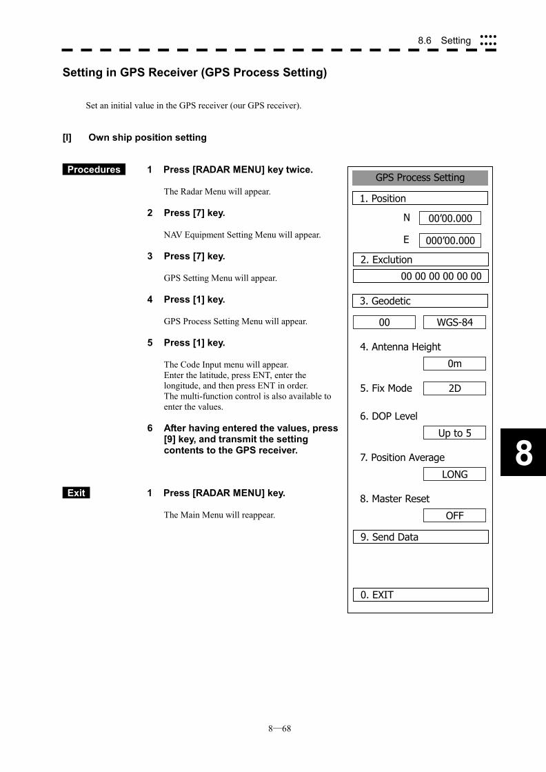
8─68
8
8.6 Setting ����
����
GPS Process Setting
1. Position
00’00.000
000’00.000
0. EXIT
00
3. Geodetic
N
E
2. Exclution
00 00 00 00 00 00
WGS-84
4. Antenna Height
0m
5. Fix Mode 2D
6. DOP Level
Up to 5
7. Position Average
LONG
8. Master Reset
OFF
9. Send Data
Setting in GPS Receiver (GPS Process Setting)
Set an initial value in the GPS receiver (our GPS receiver).
[I] Own ship position setting
Procedures 1 Press [RADAR MENU] key twice.
The Radar Menu will appear.
2 Press [7] key.
NAV Equipment Setting Menu will appear.
3 Press [7] key.
GPS Setting Menu will appear.
4 Press [1] key.
GPS Process Setting Menu will appear.
5 Press [1] key.
The Code Input menu will appear. Enter the latitude, press ENT, enter the longitude, and then press ENT in order. The multi-function control is also available to enter the values.
6 After having entered the values, press [9] key, and transmit the setting contents to the GPS receiver.
Exit 1 Press [RADAR MENU] key.
The Main Menu will reappear.
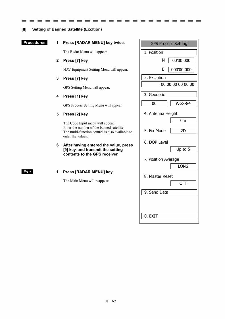
8─69
GPS Process Setting
1. Position
00’00.000
000’00.000
0. EXIT
00
3. Geodetic
N
E
2. Exclution
00 00 00 00 00 00
WGS-84
4. Antenna Height
0m
5. Fix Mode 2D
6. DOP Level
Up to 5
7. Position Average
LONG
8. Master Reset
OFF
9. Send Data
[II] Setting of Banned Satellite (Excltion)
Procedures 1 Press [RADAR MENU] key twice.
The Radar Menu will appear.
2 Press [7] key.
NAV Equipment Setting Menu will appear.
3 Press [7] key.
GPS Setting Menu will appear.
4 Press [1] key.
GPS Process Setting Menu will appear.
5 Press [2] key.
The Code Input menu will appear. Enter the number of the banned satellite. The multi-function control is also available to enter the values.
6 After having entered the value, press [9] key, and transmit the setting contents to the GPS receiver.
Exit 1 Press [RADAR MENU] key. The Main Menu will reappear.
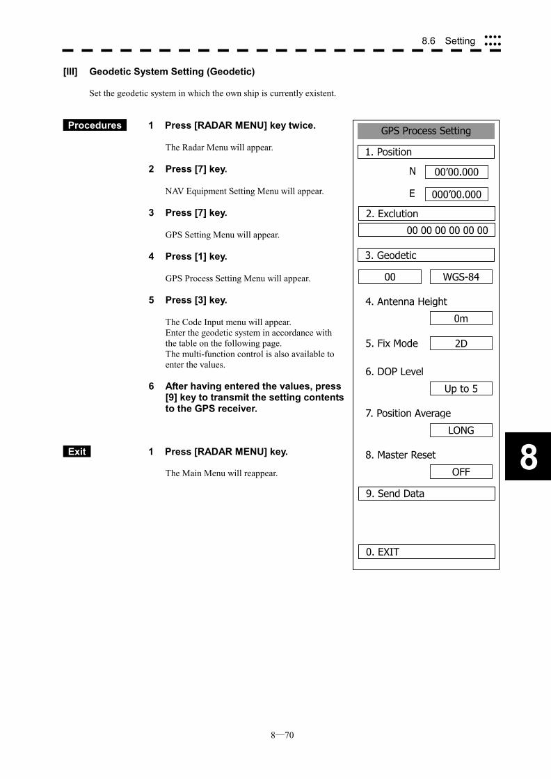
8─70
8
8.6 Setting ����
����
GPS Process Setting
1. Position
00’00.000
000’00.000
0. EXIT
00
3. Geodetic
N
E
2. Exclution
00 00 00 00 00 00
WGS-84
4. Antenna Height
0m
5. Fix Mode 2D
6. DOP Level
Up to 5
7. Position Average
LONG
8. Master Reset
OFF
9. Send Data
[III] Geodetic System Setting (Geodetic)
Set the geodetic system in which the own ship is currently existent.
Procedures 1 Press [RADAR MENU] key twice.
The Radar Menu will appear.
2 Press [7] key.
NAV Equipment Setting Menu will appear.
3 Press [7] key.
GPS Setting Menu will appear.
4 Press [1] key.
GPS Process Setting Menu will appear.
5 Press [3] key.
The Code Input menu will appear. Enter the geodetic system in accordance with the table on the following page. The multi-function control is also available to enter the values.
6 After having entered the values, press [9] key to transmit the setting contents to the GPS receiver.
Exit 1 Press [RADAR MENU] key. The Main Menu will reappear.
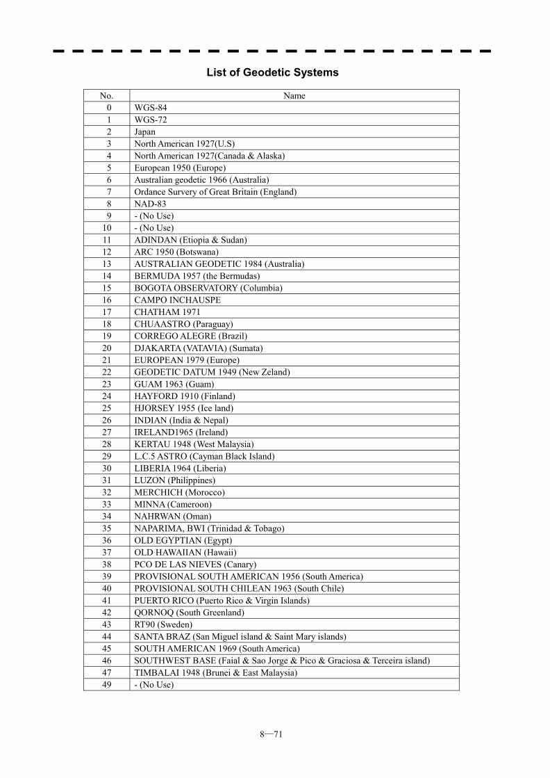
8─71
List of Geodetic Systems
No. Name 0 WGS-84 1 WGS-72 2 Japan 3 North American 1927(U.S) 4 North American 1927(Canada & Alaska) 5 European 1950 (Europe) 6 Australian geodetic 1966 (Australia) 7 Ordance Survery of Great Britain (England) 8 NAD-83 9 - (No Use)
10 - (No Use) 11 ADINDAN (Etiopia & Sudan) 12 ARC 1950 (Botswana) 13 AUSTRALIAN GEODETIC 1984 (Australia) 14 BERMUDA 1957 (the Bermudas) 15 BOGOTA OBSERVATORY (Columbia) 16 CAMPO INCHAUSPE 17 CHATHAM 1971 18 CHUAASTRO (Paraguay) 19 CORREGO ALEGRE (Brazil) 20 DJAKARTA (VATAVIA) (Sumata) 21 EUROPEAN 1979 (Europe) 22 GEODETIC DATUM 1949 (New Zeland) 23 GUAM 1963 (Guam) 24 HAYFORD 1910 (Finland) 25 HJORSEY 1955 (Ice land) 26 INDIAN (India & Nepal) 27 IRELAND1965 (Ireland) 28 KERTAU 1948 (West Malaysia) 29 L.C.5 ASTRO (Cayman Black Island) 30 LIBERIA 1964 (Liberia) 31 LUZON (Philippines) 32 MERCHICH (Morocco) 33 MINNA (Cameroon) 34 NAHRWAN (Oman) 35 NAPARIMA, BWI (Trinidad & Tobago) 36 OLD EGYPTIAN (Egypt) 37 OLD HAWAIIAN (Hawaii) 38 PCO DE LAS NIEVES (Canary) 39 PROVISIONAL SOUTH AMERICAN 1956 (South America) 40 PROVISIONAL SOUTH CHILEAN 1963 (South Chile) 41 PUERTO RICO (Puerto Rico & Virgin Islands) 42 QORNOQ (South Greenland) 43 RT90 (Sweden) 44 SANTA BRAZ (San Miguel island & Saint Mary islands) 45 SOUTH AMERICAN 1969 (South America) 46 SOUTHWEST BASE (Faial & Sao Jorge & Pico & Graciosa & Terceira island) 47 TIMBALAI 1948 (Brunei & East Malaysia) 49 - (No Use)
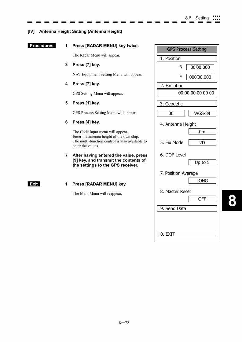
8─72
8
8.6 Setting ����
����
GPS Process Setting
1. Position
00’00.000
000’00.000
0. EXIT
00
3. Geodetic
N
E
2. Exclution
00 00 00 00 00 00
WGS-84
4. Antenna Height
0m
5. Fix Mode 2D
6. DOP Level
Up to 5
7. Position Average
LONG
8. Master Reset
OFF
9. Send Data
[IV] Antenna Height Setting (Antenna Height)
Procedures 1 Press [RADAR MENU] key twice. The Radar Menu will appear.
3 Press [7] key.
NAV Equipment Setting Menu will appear.
4 Press [7] key.
GPS Setting Menu will appear.
5 Press [1] key.
GPS Process Setting Menu will appear.
6 Press [4] key.
The Code Input menu will appear. Enter the antenna height of the own ship. The multi-function control is also available to enter the values.
7 After having entered the value, press [9] key, and transmit the contents of the settings to the GPS receiver.
Exit 1 Press [RADAR MENU] key. The Main Menu will reappear.
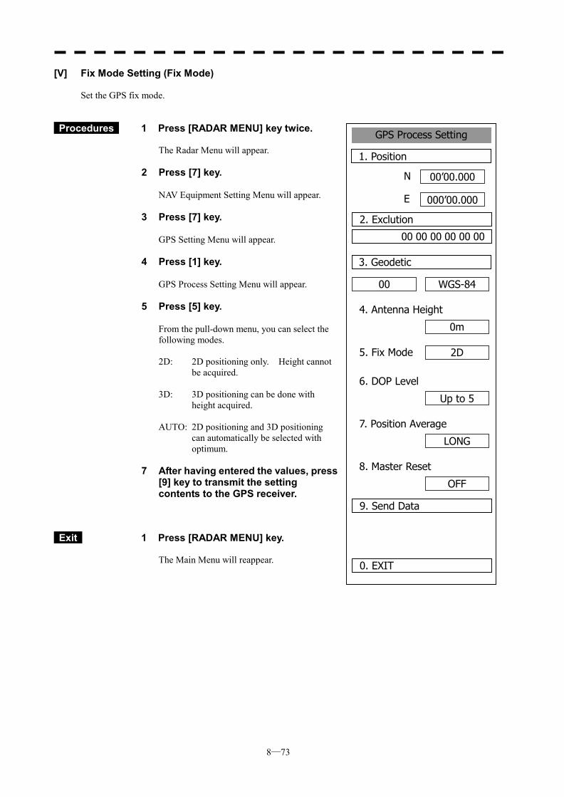
8─73
GPS Process Setting
1. Position
00’00.000
000’00.000
0. EXIT
00
3. Geodetic
N
E
2. Exclution
00 00 00 00 00 00
WGS-84
4. Antenna Height
0m
5. Fix Mode 2D
6. DOP Level
Up to 5
7. Position Average
LONG
8. Master Reset
OFF
9. Send Data
[V] Fix Mode Setting (Fix Mode) Set the GPS fix mode.
Procedures 1 Press [RADAR MENU] key twice. The Radar Menu will appear.
2 Press [7] key.
NAV Equipment Setting Menu will appear.
3 Press [7] key.
GPS Setting Menu will appear.
4 Press [1] key.
GPS Process Setting Menu will appear.
5 Press [5] key.
From the pull-down menu, you can select the following modes. 2D: 2D positioning only. Height cannot
be acquired. 3D: 3D positioning can be done with
height acquired. AUTO: 2D positioning and 3D positioning
can automatically be selected with optimum.
7 After having entered the values, press
[9] key to transmit the setting contents to the GPS receiver.
Exit 1 Press [RADAR MENU] key. The Main Menu will reappear.
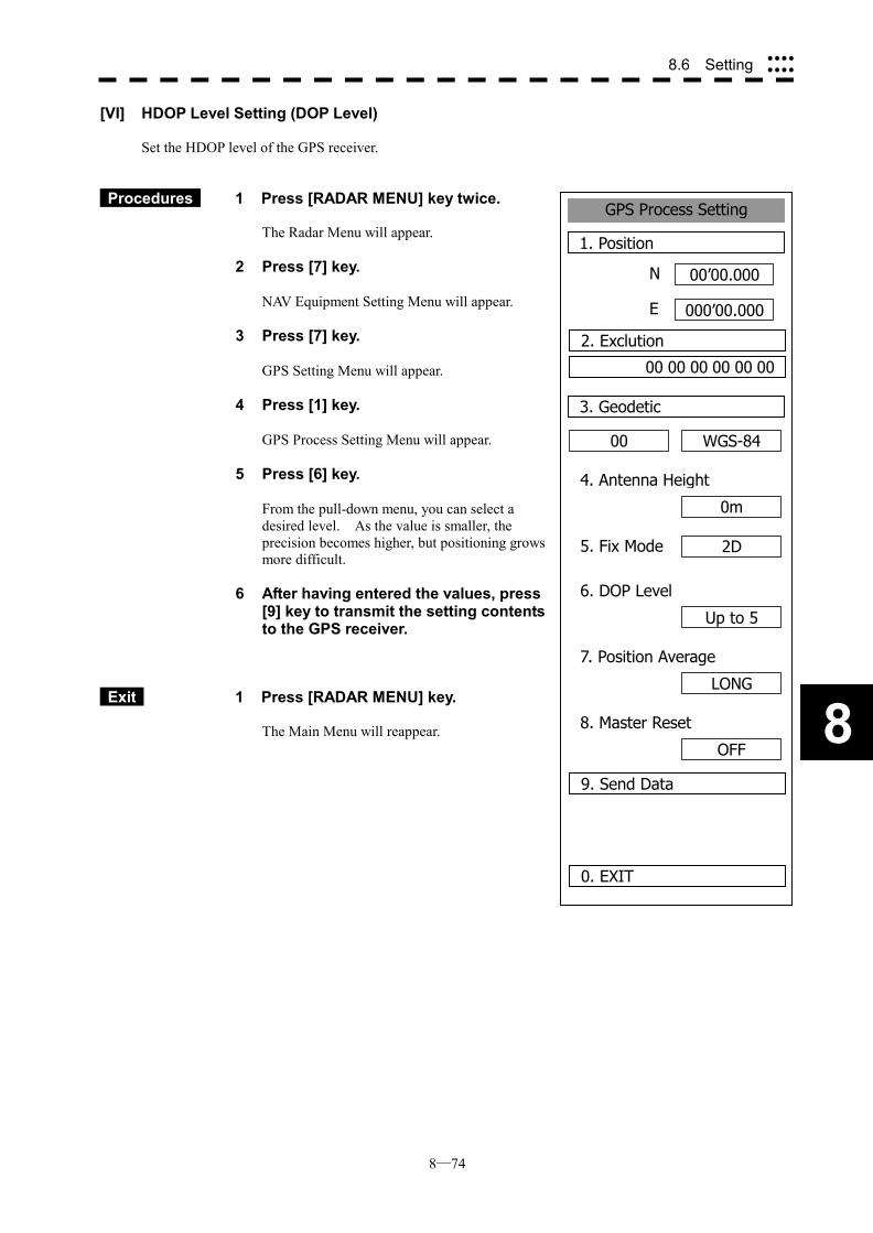
8─74
8
8.6 Setting ����
����
GPS Process Setting
1. Position
00’00.000
000’00.000
0. EXIT
00
3. Geodetic
N
E
2. Exclution
00 00 00 00 00 00
WGS-84
4. Antenna Height
0m
5. Fix Mode 2D
6. DOP Level
Up to 5
7. Position Average
LONG
8. Master Reset
OFF
9. Send Data
[VI] HDOP Level Setting (DOP Level) Set the HDOP level of the GPS receiver.
Procedures 1 Press [RADAR MENU] key twice. The Radar Menu will appear.
2 Press [7] key.
NAV Equipment Setting Menu will appear.
3 Press [7] key.
GPS Setting Menu will appear.
4 Press [1] key.
GPS Process Setting Menu will appear.
5 Press [6] key.
From the pull-down menu, you can select a desired level. As the value is smaller, the precision becomes higher, but positioning grows more difficult.
6 After having entered the values, press [9] key to transmit the setting contents to the GPS receiver.
Exit 1 Press [RADAR MENU] key. The Main Menu will reappear.
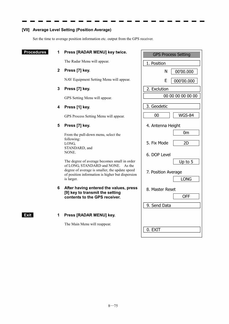
8─75
GPS Process Setting
1. Position
00’00.000
000’00.000
0. EXIT
00
3. Geodetic
N
E
2. Exclution
00 00 00 00 00 00
WGS-84
4. Antenna Height
0m
5. Fix Mode 2D
6. DOP Level
Up to 5
7. Position Average
LONG
8. Master Reset
OFF
9. Send Data
[VII] Average Level Setting (Position Average) Set the time to average position information etc. output from the GPS receiver.
Procedures 1 Press [RADAR MENU] key twice.
The Radar Menu will appear.
2 Press [7] key.
NAV Equipment Setting Menu will appear. 3 Press [7] key.
GPS Setting Menu will appear. 4 Press [1] key.
GPS Process Setting Menu will appear. 5 Press [7] key.
From the pull-down menu, select the following: LONG, STANDARD, and NONE. The degree of average becomes small in order of LONG, STANDARD and NONE. As the degree of average is smaller, the update speed of position information is higher but dispersion is larger.
6 After having entered the values, press [9] key to transmit the setting contents to the GPS receiver.
Exit 1 Press [RADAR MENU] key. The Main Menu will reappear.
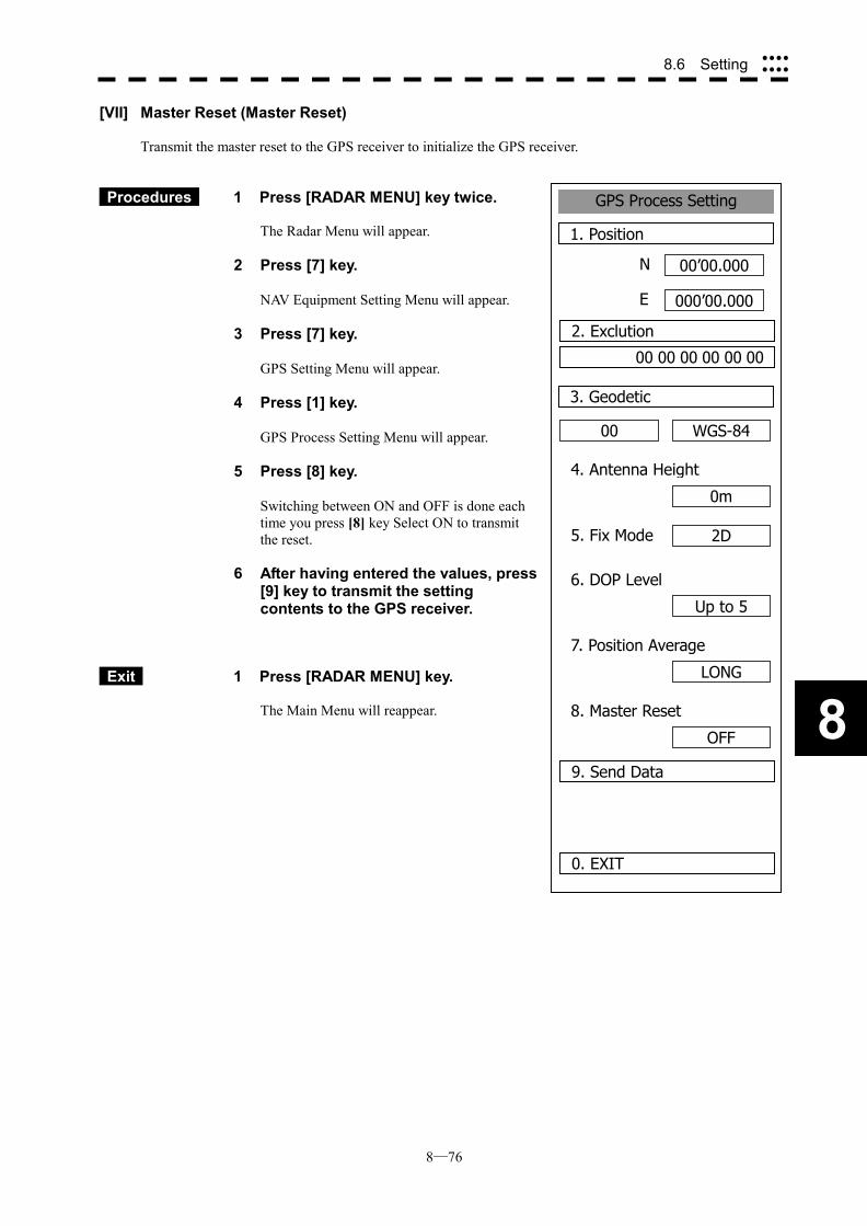
8─76
8
8.6 Setting ����
����
GPS Process Setting
1. Position
00’00.000
000’00.000
0. EXIT
00
3. Geodetic
N
E
2. Exclution
00 00 00 00 00 00
WGS-84
4. Antenna Height
0m
5. Fix Mode 2D
6. DOP Level
Up to 5
7. Position Average
LONG
8. Master Reset
OFF
9. Send Data
[VII] Master Reset (Master Reset) Transmit the master reset to the GPS receiver to initialize the GPS receiver.
Procedures 1 Press [RADAR MENU] key twice. The Radar Menu will appear.
2 Press [7] key.
NAV Equipment Setting Menu will appear.
3 Press [7] key.
GPS Setting Menu will appear.
4 Press [1] key.
GPS Process Setting Menu will appear.
5 Press [8] key.
Switching between ON and OFF is done each time you press [8] key Select ON to transmit the reset.
6 After having entered the values, press [9] key to transmit the setting contents to the GPS receiver.
Exit 1 Press [RADAR MENU] key. The Main Menu will reappear.
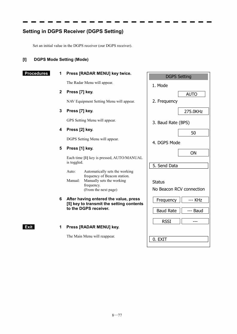
8─77
DGPS Setting
1. Mode
AUTO
0. EXIT
2. Frequency
5. Send Data
275.0KHz
3. Baud Rate (BPS)
50
4. DGPS Mode
ON
Status
No Beacon RCV connection
Frequency --- KHz
Baud Rate --- Baud
RSSI ---
Setting in DGPS Receiver (DGPS Setting)
Set an initial value in the DGPS receiver (our DGPS receiver).
[I] DGPS Mode Setting (Mode)
Procedures 1 Press [RADAR MENU] key twice. The Radar Menu will appear.
2 Press [7] key.
NAV Equipment Setting Menu will appear. 3 Press [7] key.
GPS Setting Menu will appear.
4 Press [2] key.
DGPS Setting Menu will appear.
5 Press [1] key.
Each time [1] key is pressed, AUTO/MANUAL is toggled. Auto: Automatically sets the working
frequency of Beacon station. Manual: Manually sets the working
frequency. (From the next page)
6 After having entered the value, press [5] key to transmit the setting contents to the DGPS receiver.
Exit 1 Press [RADAR MENU] key. The Main Menu will reappear.
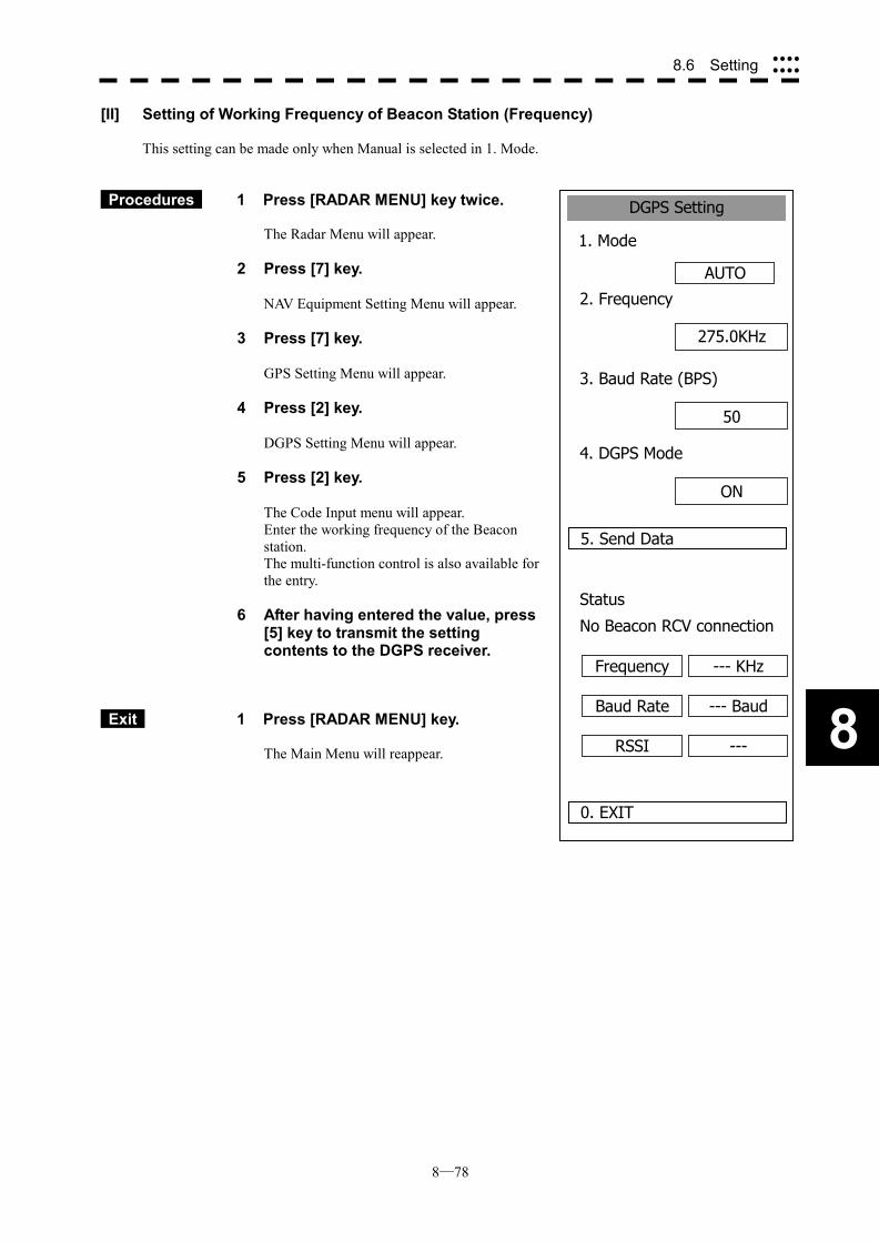
8─78
8
8.6 Setting ����
����
DGPS Setting
1. Mode
AUTO
0. EXIT
2. Frequency
5. Send Data
275.0KHz
3. Baud Rate (BPS)
50
4. DGPS Mode
ON
Status
No Beacon RCV connection
Frequency --- KHz
Baud Rate --- Baud
RSSI ---
[II] Setting of Working Frequency of Beacon Station (Frequency) This setting can be made only when Manual is selected in 1. Mode.
Procedures 1 Press [RADAR MENU] key twice. The Radar Menu will appear.
2 Press [7] key.
NAV Equipment Setting Menu will appear.
3 Press [7] key.
GPS Setting Menu will appear.
4 Press [2] key.
DGPS Setting Menu will appear.
5 Press [2] key.
The Code Input menu will appear. Enter the working frequency of the Beacon station. The multi-function control is also available for the entry.
6 After having entered the value, press [5] key to transmit the setting contents to the DGPS receiver.
Exit 1 Press [RADAR MENU] key. The Main Menu will reappear.
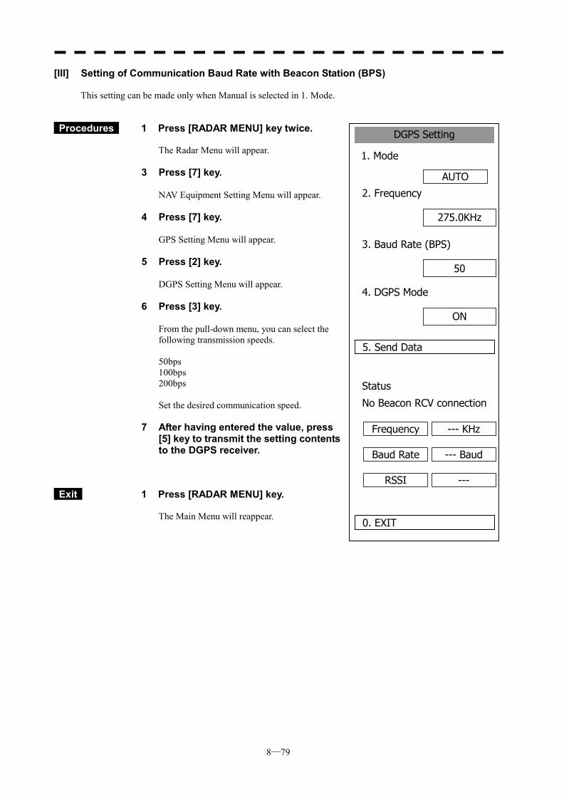
8─79
DGPS Setting
1. Mode
AUTO
0. EXIT
2. Frequency
5. Send Data
275.0KHz
3. Baud Rate (BPS)
50
4. DGPS Mode
ON
Status
No Beacon RCV connection
Frequency --- KHz
Baud Rate --- Baud
RSSI ---
[III] Setting of Communication Baud Rate with Beacon Station (BPS) This setting can be made only when Manual is selected in 1. Mode.
Procedures 1 Press [RADAR MENU] key twice. The Radar Menu will appear.
3 Press [7] key.
NAV Equipment Setting Menu will appear.
4 Press [7] key.
GPS Setting Menu will appear.
5 Press [2] key.
DGPS Setting Menu will appear.
6 Press [3] key.
From the pull-down menu, you can select the following transmission speeds. 50bps 100bps 200bps Set the desired communication speed.
7 After having entered the value, press [5] key to transmit the setting contents to the DGPS receiver.
Exit 1 Press [RADAR MENU] key. The Main Menu will reappear.
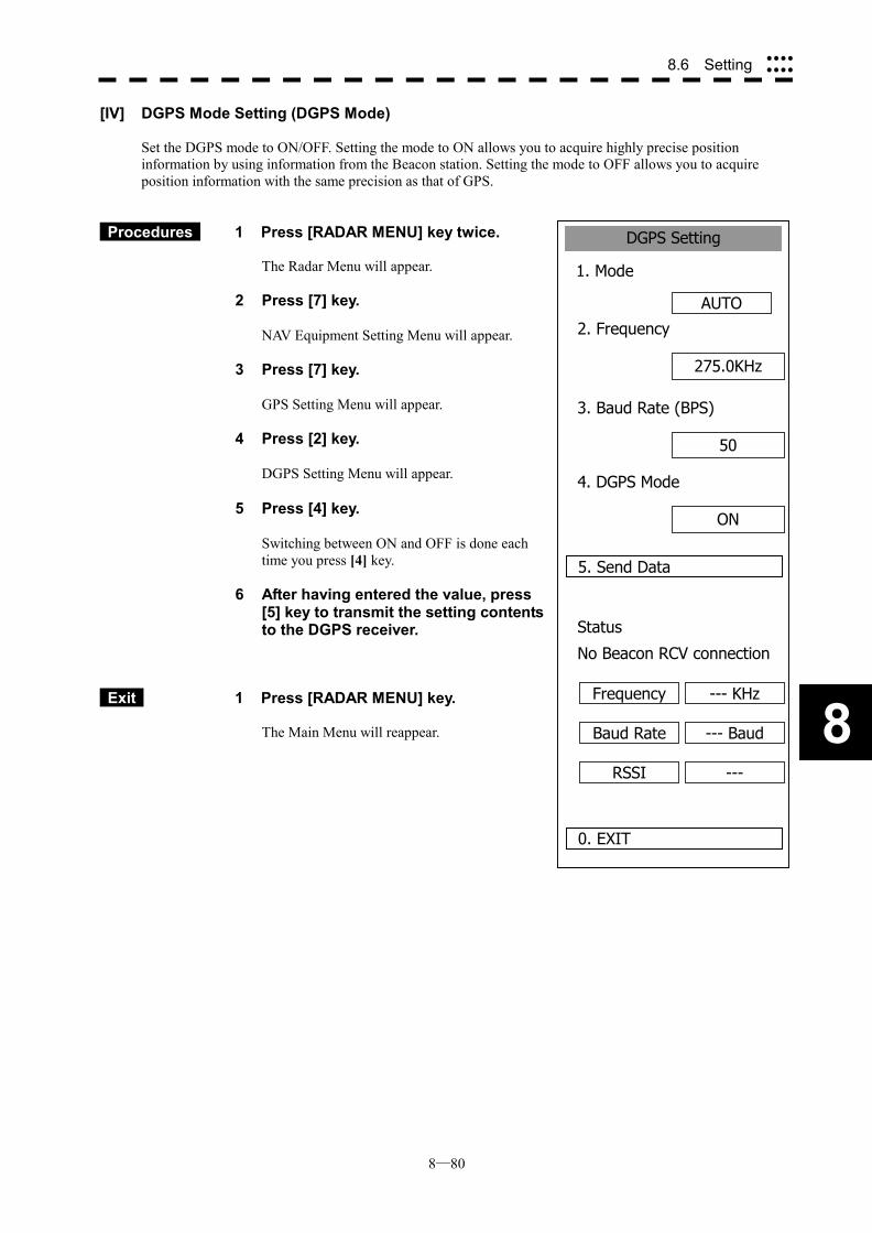
8─80
8
8.6 Setting ����
����
DGPS Setting
1. Mode
AUTO
0. EXIT
2. Frequency
5. Send Data
275.0KHz
3. Baud Rate (BPS)
50
4. DGPS Mode
ON
Status
No Beacon RCV connection
Frequency --- KHz
Baud Rate --- Baud
RSSI ---
[IV] DGPS Mode Setting (DGPS Mode) Set the DGPS mode to ON/OFF. Setting the mode to ON allows you to acquire highly precise position information by using information from the Beacon station. Setting the mode to OFF allows you to acquire position information with the same precision as that of GPS.
Procedures 1 Press [RADAR MENU] key twice. The Radar Menu will appear.
2 Press [7] key.
NAV Equipment Setting Menu will appear.
3 Press [7] key.
GPS Setting Menu will appear.
4 Press [2] key.
DGPS Setting Menu will appear. 5 Press [4] key.
Switching between ON and OFF is done each time you press [4] key.
6 After having entered the value, press [5] key to transmit the setting contents to the DGPS receiver.
Exit 1 Press [RADAR MENU] key. The Main Menu will reappear.
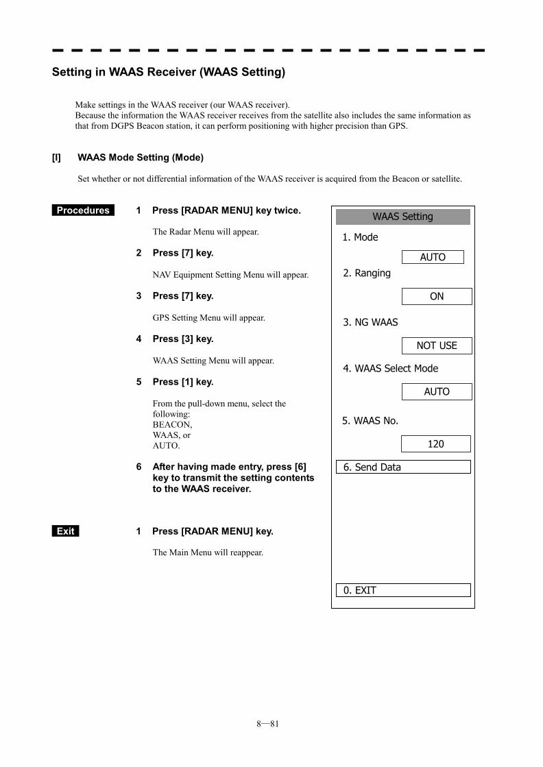
8─81
WAAS Setting
1. Mode
AUTO
0. EXIT
2. Ranging
6. Send Data
ON
3. NG WAAS
NOT USE
4. WAAS Select Mode
AUTO
5. WAAS No.
120
Setting in WAAS Receiver (WAAS Setting)
Make settings in the WAAS receiver (our WAAS receiver). Because the information the WAAS receiver receives from the satellite also includes the same information as that from DGPS Beacon station, it can perform positioning with higher precision than GPS.
[I] WAAS Mode Setting (Mode) Set whether or not differential information of the WAAS receiver is acquired from the Beacon or satellite.
Procedures 1 Press [RADAR MENU] key twice. The Radar Menu will appear.
2 Press [7] key.
NAV Equipment Setting Menu will appear.
3 Press [7] key.
GPS Setting Menu will appear.
4 Press [3] key.
WAAS Setting Menu will appear.
5 Press [1] key.
From the pull-down menu, select the following: BEACON, WAAS, or AUTO.
6 After having made entry, press [6] key to transmit the setting contents to the WAAS receiver.
Exit 1 Press [RADAR MENU] key. The Main Menu will reappear.
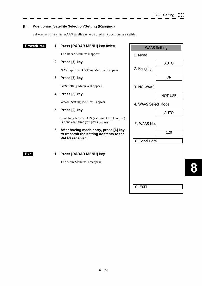
8─82
8
8.6 Setting ����
����
WAAS Setting
1. Mode
AUTO
0. EXIT
2. Ranging
6. Send Data
ON
3. NG WAAS
NOT USE
4. WAAS Select Mode
AUTO
5. WAAS No.
120
[II] Positioning Satellite Selection/Setting (Ranging) Set whether or not the WAAS satellite is to be used as a positioning satellite.
Procedures 1 Press [RADAR MENU] key twice. The Radar Menu will appear.
2 Press [7] key.
NAV Equipment Setting Menu will appear.
3 Press [7] key.
GPS Setting Menu will appear.
4 Press [3] key.
WAAS Setting Menu will appear.
5 Press [2] key.
Switching between ON (use) and OFF (not use) is done each time you press [2] key.
6 After having made entry, press [6] key to transmit the setting contents to the WAAS receiver.
Exit 1 Press [RADAR MENU] key. The Main Menu will reappear.
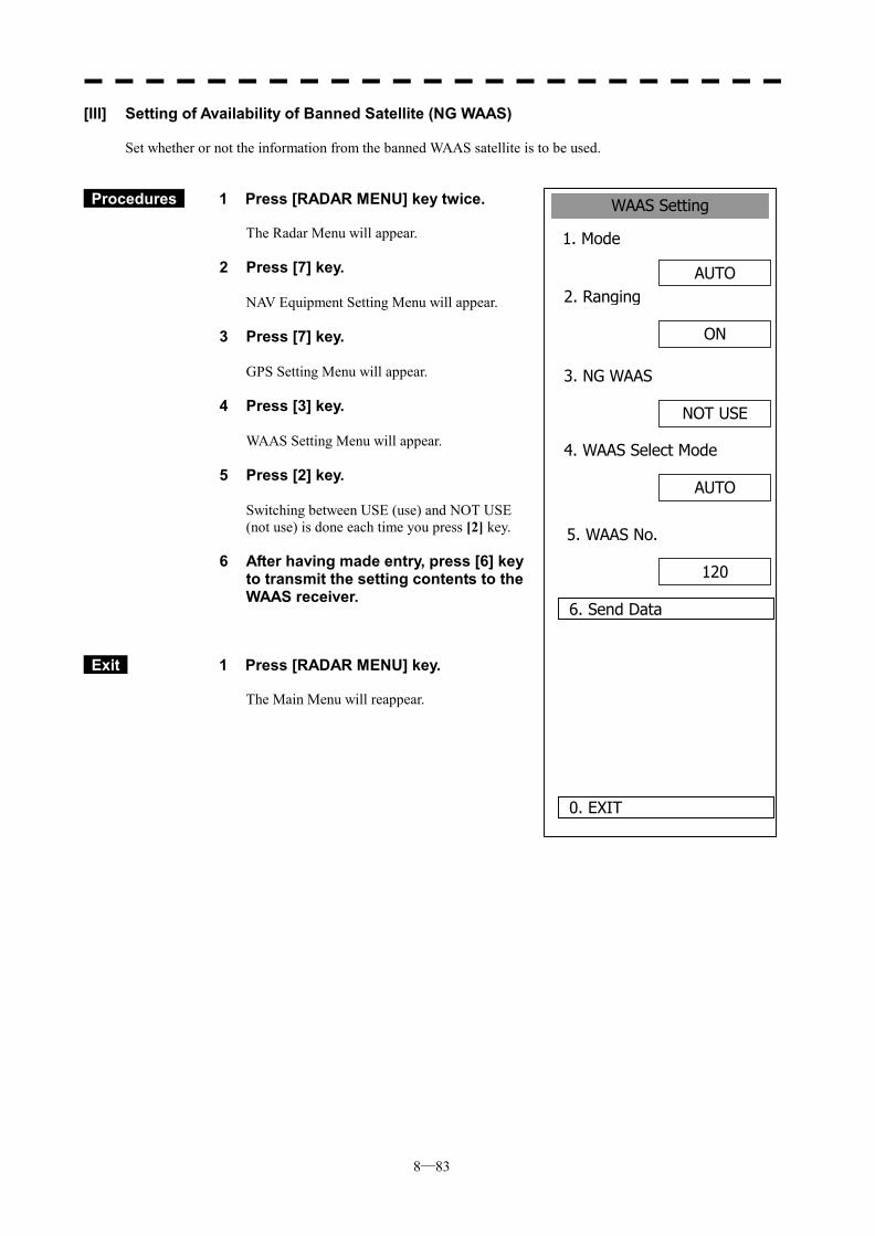
8─83
WAAS Setting
1. Mode
AUTO
0. EXIT
2. Ranging
6. Send Data
ON
3. NG WAAS
NOT USE
4. WAAS Select Mode
AUTO
5. WAAS No.
120
[III] Setting of Availability of Banned Satellite (NG WAAS) Set whether or not the information from the banned WAAS satellite is to be used.
Procedures 1 Press [RADAR MENU] key twice. The Radar Menu will appear.
2 Press [7] key.
NAV Equipment Setting Menu will appear.
3 Press [7] key.
GPS Setting Menu will appear.
4 Press [3] key.
WAAS Setting Menu will appear.
5 Press [2] key.
Switching between USE (use) and NOT USE (not use) is done each time you press [2] key.
6 After having made entry, press [6] key to transmit the setting contents to the WAAS receiver.
Exit 1 Press [RADAR MENU] key. The Main Menu will reappear.

8─84
8
8.6 Setting ����
����
WAAS Setting
1. Mode
AUTO
0. EXIT
2. Ranging
6. Send Data
ON
3. NG WAAS
NOT USE
4. WAAS Select Mode
AUTO
5. WAAS No.
120
[IV] Satellite Number Setting (WAAS Select Mode) Set the number of the WAAS satellite to be used.
Procedures 1 Press [RADAR MENU] key twice. The Radar Menu will appear.
2 Press [7] key.
NAV Equipment Setting Menu will appear.
3 Press [7] key.
GPS Setting Menu will appear.
4 Press [3] key.
WAAS Setting Menu will appear.
5 Press [4] key.
Switching between Auto and Manual is done each time you press [4] key.
6 After having made entry, press [6] key to transmit the setting contents to the WAAS receiver.
Exit 1 Press [RADAR MENU] key. The Main Menu will reappear.
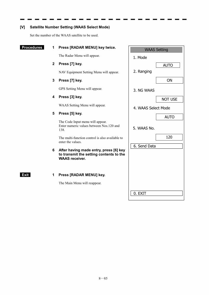
8─85
WAAS Setting
1. Mode
AUTO
0. EXIT
2. Ranging
6. Send Data
ON
3. NG WAAS
NOT USE
4. WAAS Select Mode
AUTO
5. WAAS No.
120
[V] Satellite Number Setting (WAAS Select Mode) Set the number of the WAAS satellite to be used.
Procedures 1 Press [RADAR MENU] key twice. The Radar Menu will appear.
2 Press [7] key.
NAV Equipment Setting Menu will appear.
3 Press [7] key.
GPS Setting Menu will appear.
4 Press [3] key.
WAAS Setting Menu will appear.
5 Press [5] key.
The Code Input menu will appear. Enter numeric values between Nos.120 and 138. The multi-function control is also available to enter the values.
6 After having made entry, press [6] key to transmit the setting contents to the WAAS receiver.
Exit 1 Press [RADAR MENU] key. The Main Menu will reappear.
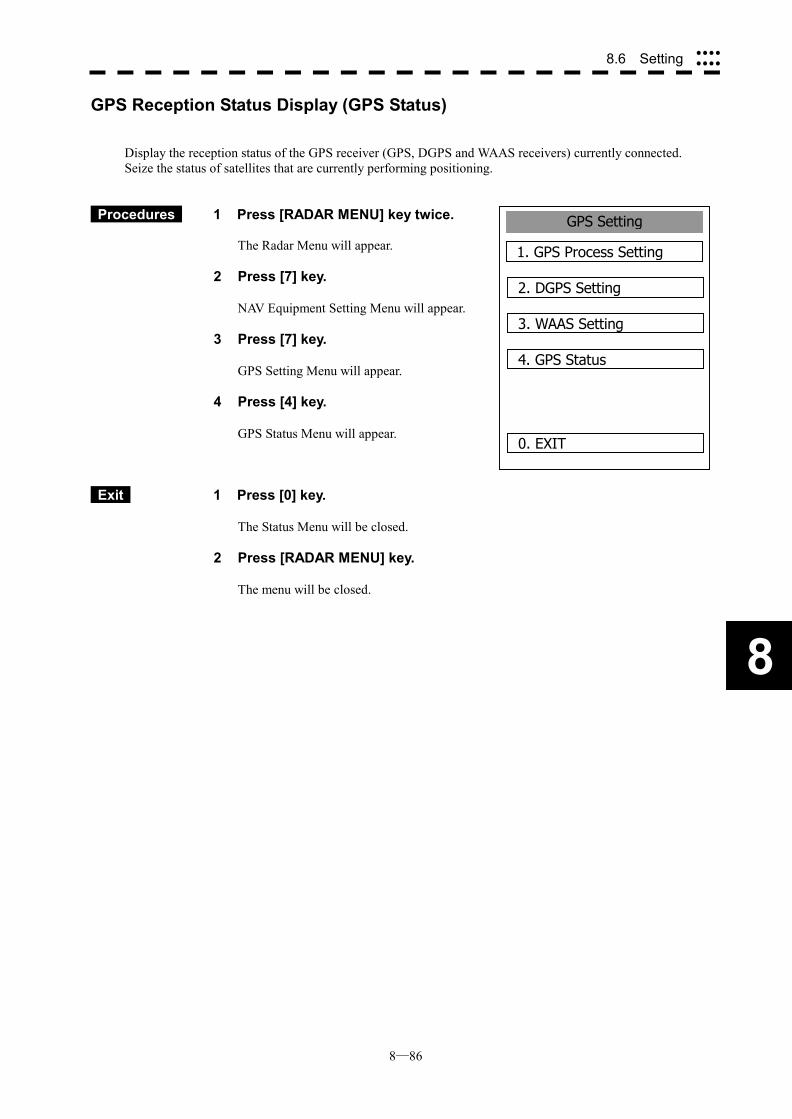
8─86
8
8.6 Setting ����
����
GPS Setting
1. GPS Process Setting
0. EXIT
2. DGPS Setting
3. WAAS Setting
4. GPS Status
GPS Reception Status Display (GPS Status)
Display the reception status of the GPS receiver (GPS, DGPS and WAAS receivers) currently connected. Seize the status of satellites that are currently performing positioning.
Procedures 1 Press [RADAR MENU] key twice. The Radar Menu will appear.
2 Press [7] key.
NAV Equipment Setting Menu will appear.
3 Press [7] key.
GPS Setting Menu will appear.
4 Press [4] key.
GPS Status Menu will appear.
Exit 1 Press [0] key.
The Status Menu will be closed.
2 Press [RADAR MENU] key.
The menu will be closed.
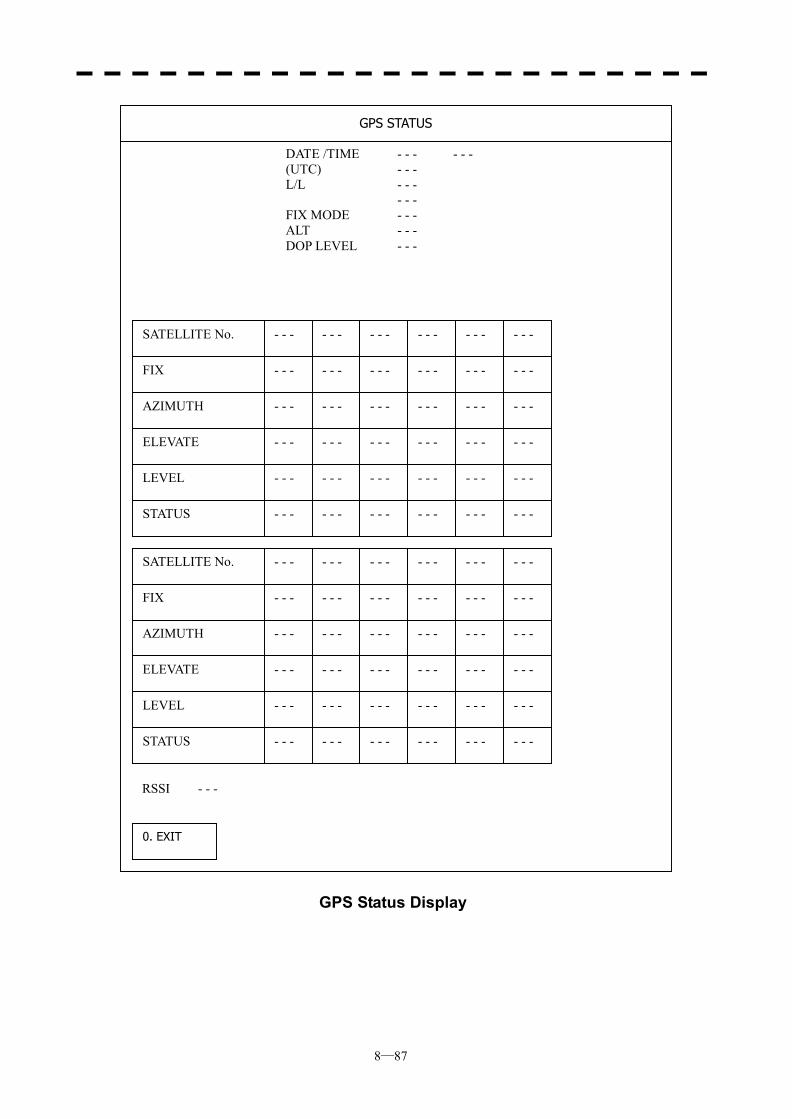
8─87
GPS Status Display
DATE /TIME - - - - - - (UTC) - - - L/L - - - - - - FIX MODE - - - ALT - - - DOP LEVEL - - -
SATELLITE No.
FIX
AZIMUTH
ELEVATE
LEVEL
STATUS
- - - - - - - - - - - - - - - - - -
- - - - - - - - - - - - - - - - - -
- - - - - - - - - - - - - - - - - -
- - - - - - - - - - - - - - - - - -
- - - - - - - - - - - - - - - - - -
- - - - - - - - - - - - - - - - - -
SATELLITE No.
FIX
AZIMUTH
ELEVATE
LEVEL
STATUS
- - - - - - - - - - - - - - - - - -
- - - - - - - - - - - - - - - - - -
- - - - - - - - - - - - - - - - - -
- - - - - - - - - - - - - - - - - -
- - - - - - - - - - - - - - - - - -
- - - - - - - - - - - - - - - - - -
0. EXIT
RSSI - - -
GPS STATUS
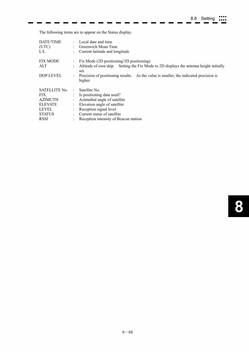
8─88
8
8.6 Setting ����
����
The following items are to appear on the Status display. DATE/TIME : Local date and time (UTC) : Greenwich Mean Time L/L : Current latitude and longitude FIX MODE : Fix Mode (2D positioning/3D positioning) ALT : Altitude of own ship. Setting the Fix Mode to 2D displays the antenna height initially
set. DOP LEVEL : Precision of positioning results. As the value is smaller, the indicated precision is
higher. SATELLITE No. : Satellite No. FIX : Is positioning data used? AZIMUTH : Azimuthal angle of satellite ELEVATE : Elevation angle of satellite LEVEL : Reception signal level STATUS : Current status of satellite RSSI : Reception intensity of Beacon station
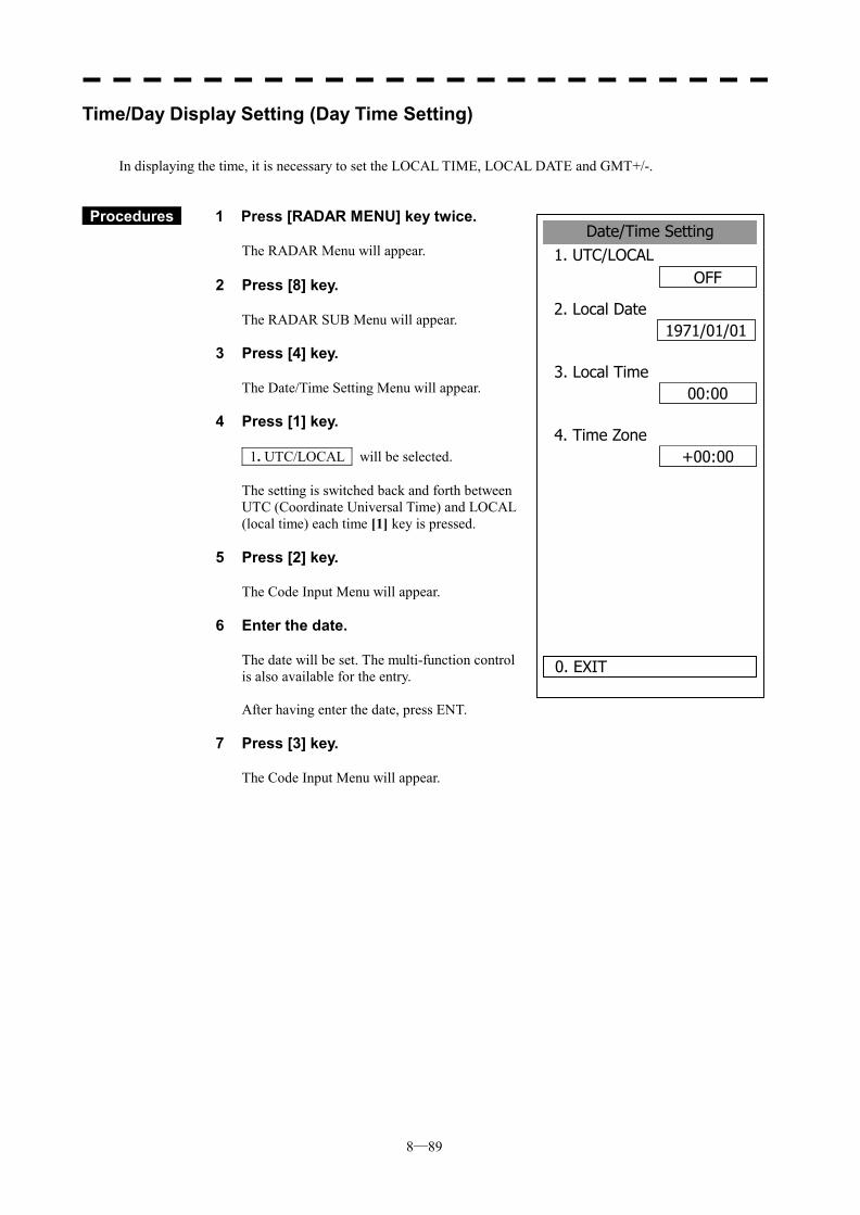
8─89
Date/Time Setting1. UTC/LOCAL
OFF
2. Local Date1971/01/01
00:00
0. EXIT
3. Local Time
+00:004. Time Zone
Time/Day Display Setting (Day Time Setting)
In displaying the time, it is necessary to set the LOCAL TIME, LOCAL DATE and GMT+/-.
Procedures 1 Press [RADAR MENU] key twice.
The RADAR Menu will appear. 2 Press [8] key.
The RADAR SUB Menu will appear.
3 Press [4] key.
The Date/Time Setting Menu will appear.
4 Press [1] key.
1. UTC/LOCAL will be selected. The setting is switched back and forth between UTC (Coordinate Universal Time) and LOCAL (local time) each time [1] key is pressed.
5 Press [2] key.
The Code Input Menu will appear.
6 Enter the date.
The date will be set. The multi-function control is also available for the entry. After having enter the date, press ENT.
7 Press [3] key.
The Code Input Menu will appear.
8─90
8
8.6 Setting ����
����
8 Enter the time.
The time will be set. The multi-function control is also available for the entry. After having enter the time, press ENT.
9 Press [4] key.
The Code Input Menu will appear.
10 Enter the time difference.
The time difference will be set. The multi-function control is also available for the entry. After having enter the value, press ENT.
Exit 1 Press [RADAR MENU] key.
The menu will be closed.
��Time correction is not available when the “ZDA” sentence of NMEA0183 is not received.
Attention
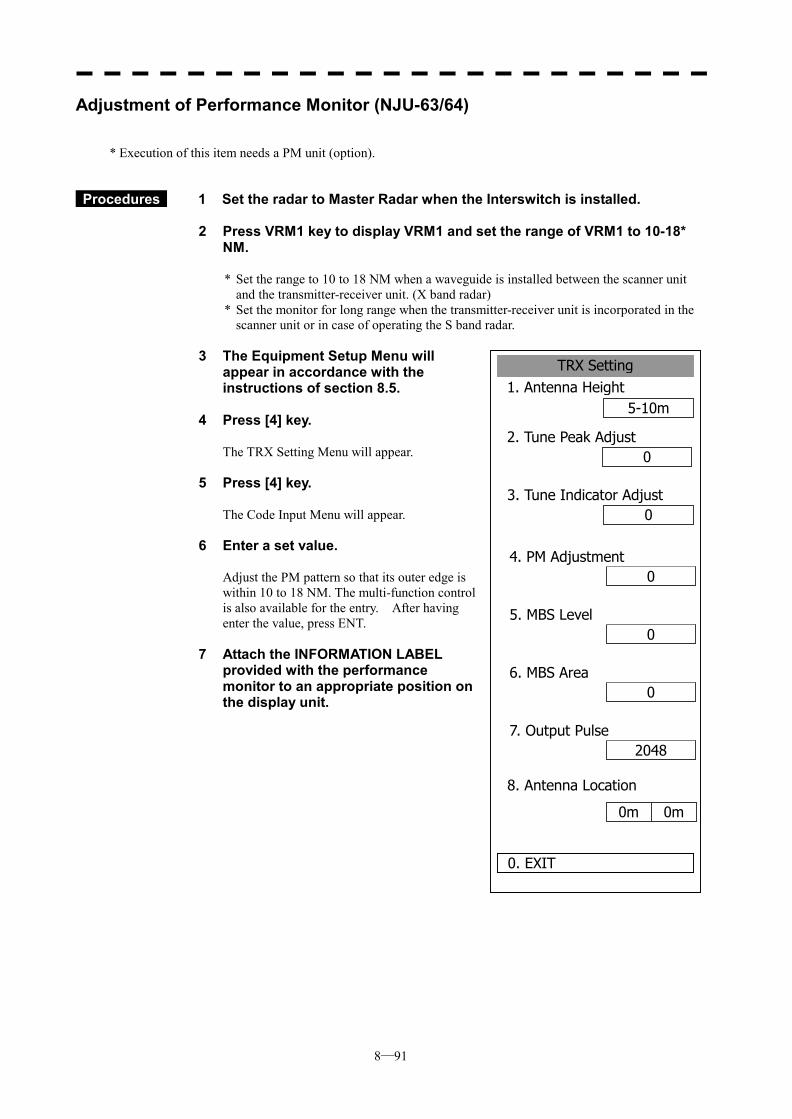
8─91
TRX Setting1. Antenna Height
5-10m
2. Tune Peak Adjust0
0
8. Antenna Location
0. EXIT
3. Tune Indicator Adjust
04. PM Adjustment
05. MBS Level
06. MBS Area
20487. Output Pulse
0m 0m
Adjustment of Performance Monitor (NJU-63/64)
* Execution of this item needs a PM unit (option).
Procedures 1 Set the radar to Master Radar when the Interswitch is installed. 2 Press VRM1 key to display VRM1 and set the range of VRM1 to 10-18*
NM.
* Set the range to 10 to 18 NM when a waveguide is installed between the scanner unit and the transmitter-receiver unit. (X band radar)
* Set the monitor for long range when the transmitter-receiver unit is incorporated in the scanner unit or in case of operating the S band radar.
3 The Equipment Setup Menu will
appear in accordance with the instructions of section 8.5.
4 Press [4] key.
The TRX Setting Menu will appear.
5 Press [4] key.
The Code Input Menu will appear.
6 Enter a set value.
Adjust the PM pattern so that its outer edge is within 10 to 18 NM. The multi-function control is also available for the entry. After having enter the value, press ENT.
7 Attach the INFORMATION LABEL provided with the performance monitor to an appropriate position on the display unit.
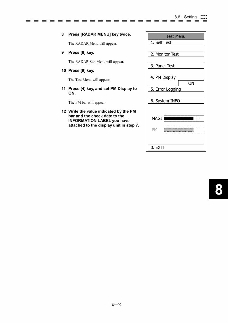
8─92
8
8.6 Setting ����
����
8 Press [RADAR MENU] key twice.
The RADAR Menu will appear.
9 Press [8] key.
The RADAR Sub Menu will appear.
10 Press [9] key.
The Test Menu will appear.
11 Press [4] key, and set PM Display to ON.
The PM bar will appear.
12 Write the value indicated by the PM bar and the check date to the INFORMATION LABEL you have attached to the display unit in step 7.
Test Menu 1. Self Test
2. Monitor Test
3. Panel Test
4. PM DisplayON
5. Error Logging
6. System INFO
0. EXIT
MAGI
PM
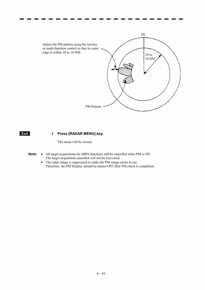
8─93
Exit 1 Press [RADAR MENU] key.
The menu will be closed.
Note: � All target acquisitions by ARPA functions will be cancelled when PM is ON. The target acquisition cancelled will not be recovered. � The radar image is suppressed to make the PM image easier to see. Therefore, the PM Display should be turned OFF after PM check is completed.
Adjust the PM pattern using the ten-key or multi-function control so that its outer edge is within 10 to 18 NM.
PM Pattern
10 to 18 NM
HL

SECTION 9 AFTER-SALES SERVICE
9─1
・・・・・・ When you Request for Repair・・・・・・・・・・・・・・・・・・・・・・・・・・・・・・・ If you suppose the product may be out of order, read the description in Section 8 carefully and check the suspected point again. If it is still out of order, you are recommended to stop operation of the equipment and consult with the dealer from whom you purchased the product, or our branch office in your country or district, the sales department in our main office in Tokyo. � Repair within the Warranty Period If any failure occurs in the product during its normal operation in accordance with the
instruction manual, the dealer or JRC will repair free of charge. In case that any failure is caused due to misuse, faulty operation, negligence or force major such as natural disaster and fire, the product will be repaired with charges.
� Repair after the Warranty Period If any defective function of the product is recoverable by repair, the repair of it will be made at
your own charge upon your request. � Necessary Information for Repair
☆ Product name, model, manufacturing date and serial number ☆ Trouble conditions (as detailed as possible. Refer to “Radar Failure Check List” in page
9-2. ) ☆ Name of company/organization, address and telephone number
・・・・・・ Recommended Maintenance ・・・・・・・・・・・・・・・・・・・・・・・・・・・・・・・ The performance of the product may deteriorate due to the secular change of the parts used in it, though such deterioration depends upon the conditions of operation. So checkup and maintenance is recommendable for the product in addition to your daily care. For maintenance, consult with the near-by dealer or our sales department. Such maintenance will be made with charges. For further details of after-sale service, contact the JRC Offices in the list at the end of this manual.
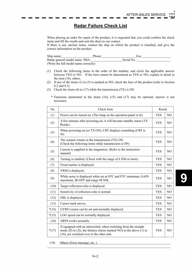
9─2
AFTER-SALES SERVICE�
����
����
9
Radar Failure Check List When placing an order for repair of the product, it is requested that you could confirm the check items and fill the results and sent the sheet to our contact. If there is any unclear items, contact the ship on which the product is installed, and give the correct information on the product. Ship name: Phone: Fax: Radar general model name: JMA- Serial No. : (Write the full model name correctly) (1) Check the following items in the order of the number, and circle the applicable answer
between YES or NO. If the item cannot be determined as YES or NO, explain in detail in the item (18), others.
(2) If any of the items (1) to (5) is marked as NO, check the fuse of the product (refer to Section 8.2 and 8.3).
(3) Check the items (4) to (17) while the transmission (TX) is ON.
* Functions mentioned in the items (14), (15) and (17) may be optional, answer is not necessary.
No. Check Item Result
(1) Power can be turned on. (The lamp on the operation panel is lit) YES NO
(2) A few minutes after powering-on, it will become standby status (TX Ready). YES NO
(3) When powering-on (or TX ON), CRT displays something (CRT is lit). YES NO
(4) The scanner rotates at the transmission (TX) ON. (Check the following items while transmission is ON) YES NO
(5) Current is supplied to the magnetron. (Refer to the instruction manual) YES NO
(6) Turning is enabled. (Check with the range of 6 NM or more) YES NO
(7) Fixed marker is displayed. YES NO
(8) VRM is displayed. YES NO
(9) While noise is displayed while set at STC and FTC minimum, GAIN maximum, IR-OFF and range 48 NM. YES NO
(10) Target reflection echo is displayed. YES NO
(11) Sensitivity of reflection echo is normal. YES NO
(12) EBL is displayed. YES NO
(13) Cursor mark moves. YES NO
*(14) GYRO course can be set and normally displayed. YES NO
*(15) LOG speed can be normally displayed. YES NO
(16) ARPA works normally. YES NO
*(17) If equipped with an interswitch, when switching from the straight mode (II) to (X), the failures (items marked NO) in the above (1) to (16), are switched over to the other unit.
YES NO
(18) Others (Error message, etc. )

SECTION 10 DISPOSAL
10.1 DISPOSAL OF THE UNIT ...................10-1 10.2 DISPOSAL OF USED BATTERIES.....10-2 10.3 DISPOSAL OF USED MAGNETRON .10-3

10─1
DISPOSAL 10.1 DISPOSAL OF THE UNIT
When disposing of this unit, be sure to follow the local laws and regulations for the place of disposal.
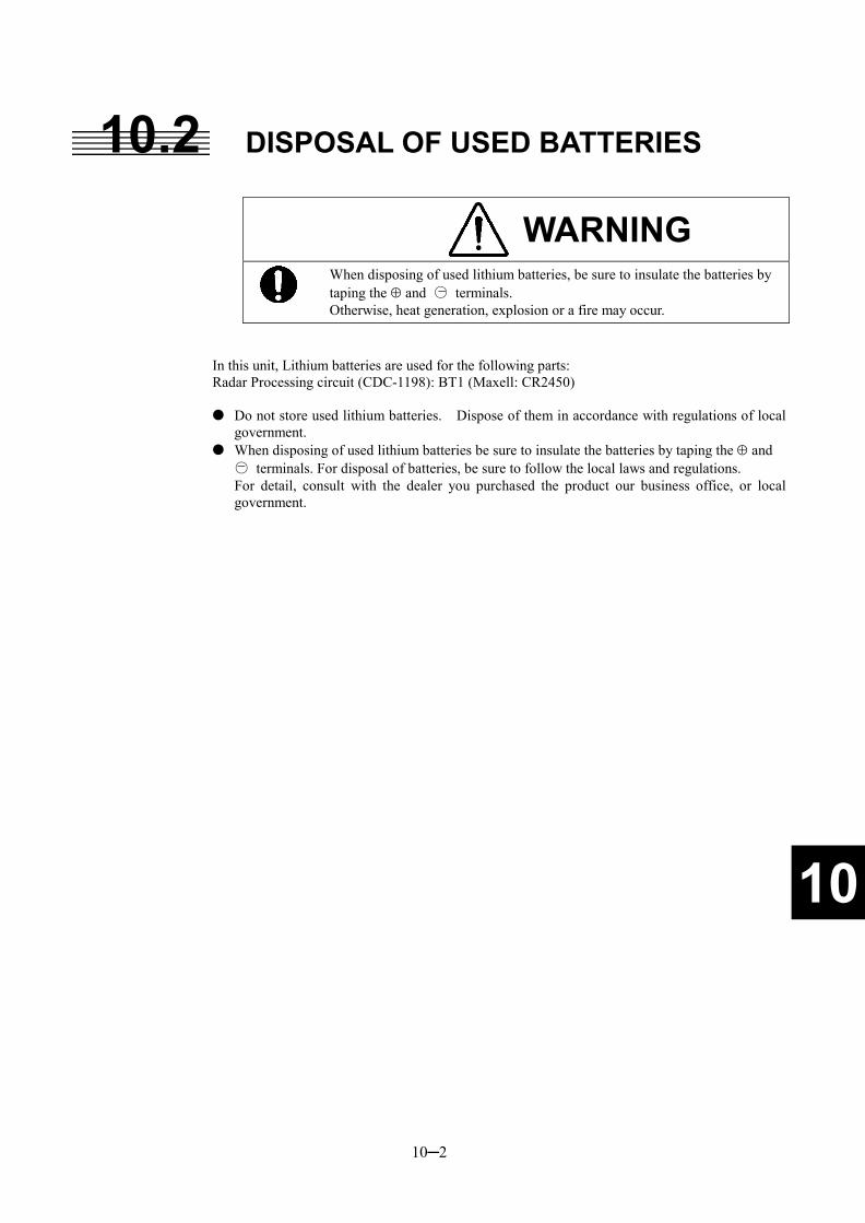
10─2
10
10.2 DISPOSAL OF USED BATTERIES
WARNING
When disposing of used lithium batteries, be sure to insulate the batteries by taping the � and ○ terminals. Otherwise, heat generation, explosion or a fire may occur.
In this unit, Lithium batteries are used for the following parts: Radar Processing circuit (CDC-1198): BT1 (Maxell: CR2450) � Do not store used lithium batteries. Dispose of them in accordance with regulations of local
government. � When disposing of used lithium batteries be sure to insulate the batteries by taping the � and
○ terminals. For disposal of batteries, be sure to follow the local laws and regulations. For detail, consult with the dealer you purchased the product our business office, or local
government.
�
�

10─3
10.3 DISPOSAL OF USED MAGNETRON Magnetron is used in the Scanner (NKE-2102/2252/1075) � When the magnetron is replaced with a new one, return the used magnetron to our dealer or
business office. For detail, consult with our dealer or business office.
SECTION 11 SPECIFICATIONS
11.1 JMA-5310-6 TYPE RADAR ............................................... 11-1 11.2 JMA-5320-7/9 TYPE RADAR ............................................ 11-2 11.3 JMA-5330-12 TYPE RADAR ............................................. 11-3 11.4 SCANNER (NKE-2102)...................................................... 11-4 11.5 SCANNER (NKE-2252)...................................................... 11-5 11.6 SCANNER (NKE-1075)...................................................... 11-6 11.7 DISPLAY UNIT(NCD-4510)................................................ 11-7 11.8 PROCESSOR UNIT(NDC-1273) ........................................ 11-8 11.9 PLOTTER UNIT................................................................ 11-10 11.10 ARPA-1 (HIGH PERFORMANCE ARPA) ........................ 11-12 11.11 ARPA-2 (NORMAL EDITION ATA) .................................. 11-13 11.12 KEYBOARD UNIT(NCE-7699) ........................................ 11-14 11.13 INPUT ENABLE SIGNAL................................................. 11-15 11.14 OUTPUT ENABLE SIGNAL............................................. 11-16 11.15 STANDARD CONFIGURATION....................................... 11-17 11.16 EQUIPMENT DISTANCE BETWEEN OTHER
INSTRUMENTS................................................................ 11-18 11.17 OTHERS (OPTION).......................................................... 11-19
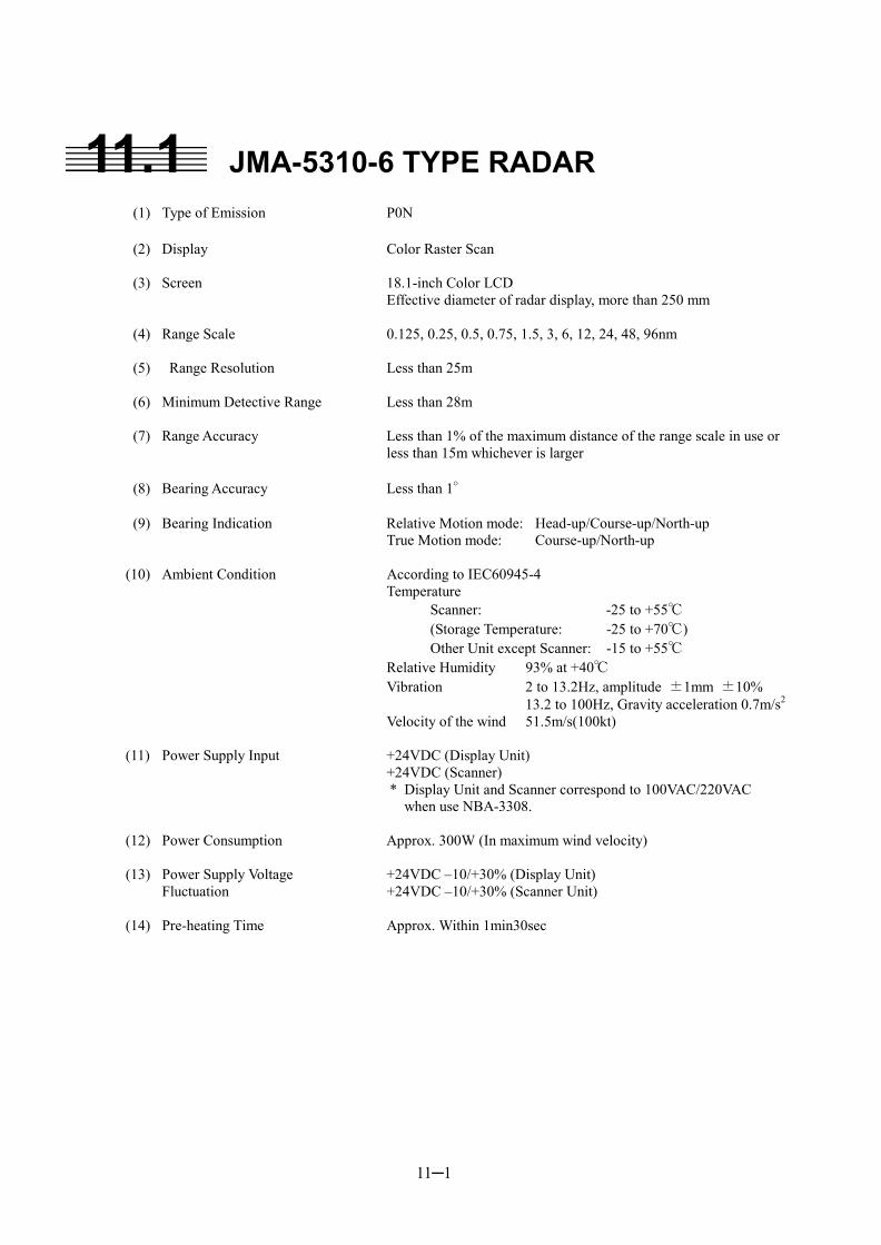
11─1
11.1 JMA-5310-6 TYPE RADAR (1) Type of Emission P0N (2) Display Color Raster Scan (3) Screen 18.1-inch Color LCD
Effective diameter of radar display, more than 250 mm (4) Range Scale 0.125, 0.25, 0.5, 0.75, 1.5, 3, 6, 12, 24, 48, 96nm (5) Range Resolution Less than 25m (6) Minimum Detective Range Less than 28m (7) Range Accuracy Less than 1% of the maximum distance of the range scale in use or
less than 15m whichever is larger (8) Bearing Accuracy Less than 1° (9) Bearing Indication Relative Motion mode: Head-up/Course-up/North-up True Motion mode: Course-up/North-up (10) Ambient Condition According to IEC60945-4 Temperature Scanner: -25 to +55℃ (Storage Temperature: -25 to +70℃) Other Unit except Scanner: -15 to +55℃ Relative Humidity 93% at +40℃ Vibration 2 to 13.2Hz, amplitude ±1mm ±10% 13.2 to 100Hz, Gravity acceleration 0.7m/s2 Velocity of the wind 51.5m/s(100kt) (11) Power Supply Input +24VDC (Display Unit) +24VDC (Scanner)
* Display Unit and Scanner correspond to 100VAC/220VAC when use NBA-3308.
(12) Power Consumption Approx. 300W (In maximum wind velocity) (13) Power Supply Voltage +24VDC –10/+30% (Display Unit) Fluctuation +24VDC –10/+30% (Scanner Unit) (14) Pre-heating Time Approx. Within 1min30sec
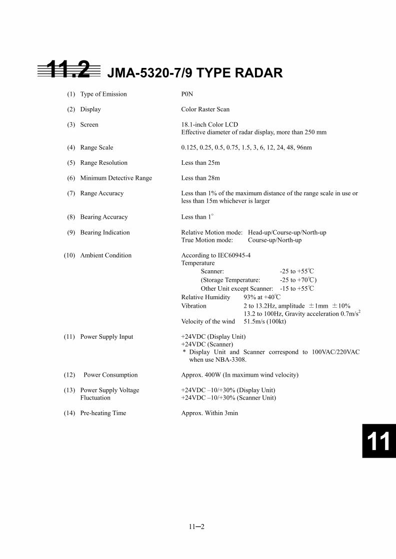
11─2
11
11.2 JMA-5320-7/9 TYPE RADAR (1) Type of Emission P0N (2) Display Color Raster Scan (3) Screen 18.1-inch Color LCD
Effective diameter of radar display, more than 250 mm (4) Range Scale 0.125, 0.25, 0.5, 0.75, 1.5, 3, 6, 12, 24, 48, 96nm (5) Range Resolution Less than 25m (6) Minimum Detective Range Less than 28m (7) Range Accuracy Less than 1% of the maximum distance of the range scale in use or
less than 15m whichever is larger (8) Bearing Accuracy Less than 1° (9) Bearing Indication Relative Motion mode: Head-up/Course-up/North-up True Motion mode: Course-up/North-up (10) Ambient Condition According to IEC60945-4 Temperature Scanner: -25 to +55℃ (Storage Temperature: -25 to +70℃) Other Unit except Scanner: -15 to +55℃ Relative Humidity 93% at +40℃ Vibration 2 to 13.2Hz, amplitude ±1mm ±10% 13.2 to 100Hz, Gravity acceleration 0.7m/s2 Velocity of the wind 51.5m/s (100kt) (11) Power Supply Input +24VDC (Display Unit) +24VDC (Scanner)
* Display Unit and Scanner correspond to 100VAC/220VAC when use NBA-3308.
(12) Power Consumption Approx. 400W (In maximum wind velocity) (13) Power Supply Voltage +24VDC –10/+30% (Display Unit) Fluctuation +24VDC –10/+30% (Scanner Unit) (14) Pre-heating Time Approx. Within 3min
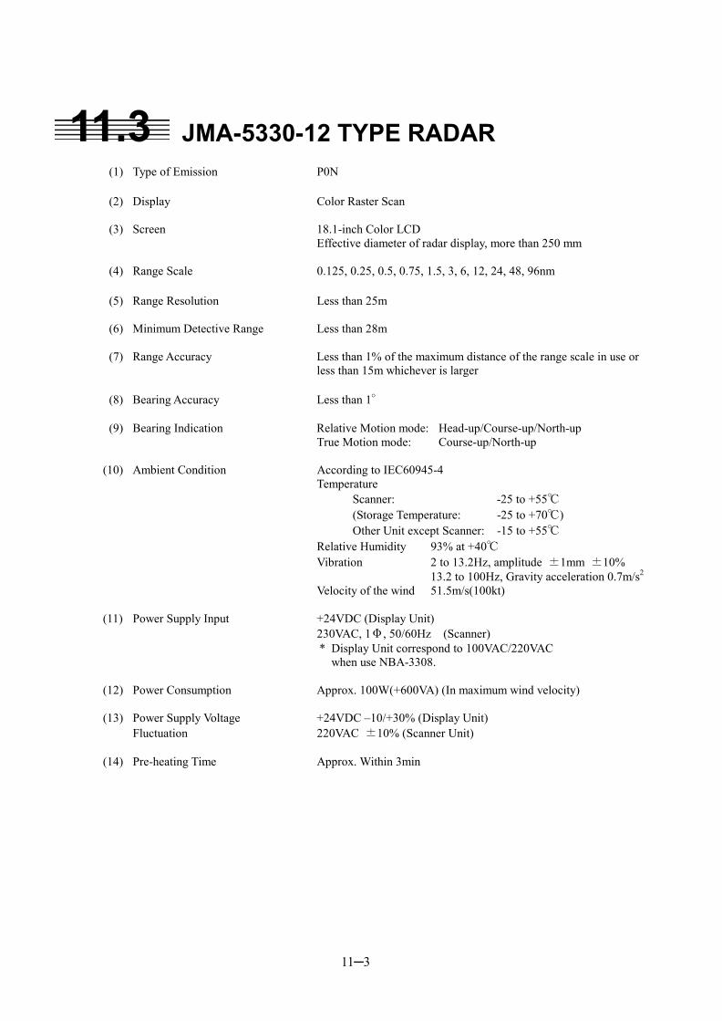
11─3
11.3 JMA-5330-12 TYPE RADAR
(1) Type of Emission P0N (2) Display Color Raster Scan (3) Screen 18.1-inch Color LCD
Effective diameter of radar display, more than 250 mm (4) Range Scale 0.125, 0.25, 0.5, 0.75, 1.5, 3, 6, 12, 24, 48, 96nm (5) Range Resolution Less than 25m (6) Minimum Detective Range Less than 28m (7) Range Accuracy Less than 1% of the maximum distance of the range scale in use or
less than 15m whichever is larger (8) Bearing Accuracy Less than 1° (9) Bearing Indication Relative Motion mode: Head-up/Course-up/North-up True Motion mode: Course-up/North-up (10) Ambient Condition According to IEC60945-4 Temperature Scanner: -25 to +55℃ (Storage Temperature: -25 to +70℃) Other Unit except Scanner: -15 to +55℃ Relative Humidity 93% at +40℃ Vibration 2 to 13.2Hz, amplitude ±1mm ±10% 13.2 to 100Hz, Gravity acceleration 0.7m/s2
Velocity of the wind 51.5m/s(100kt) (11) Power Supply Input +24VDC (Display Unit) 230VAC, 1Φ, 50/60Hz (Scanner)
* Display Unit correspond to 100VAC/220VAC when use NBA-3308.
(12) Power Consumption Approx. 100W(+600VA) (In maximum wind velocity) (13) Power Supply Voltage +24VDC –10/+30% (Display Unit) Fluctuation 220VAC ±10% (Scanner Unit) (14) Pre-heating Time Approx. Within 3min

11─4
11
11.4 SCANNER (NKE-2102)
(1) Dimensions Height 440mm�Swing Circle 1910mm (2) Mass Approx. 31kg (3) Polarization Horizontal Polarization (4) Directional Characteristic Horizontal Beam Width: 1.2� (-3dB width) Vertical Beam Width: 20� (-3dB width) Sidelobe Level: Below –26dB (within �10�) Below –30dB (outside �10�) (5) Revolution Approx. 27rpm (Normal) (6) Peak Power 10kW (7) Transmitting Frequency 9410 �30MHz (8) Transmitting Tube Magnetron [MSF1425B] (9) Pulse width/Repetition Frequency
Short Middle Long 0.125nm 0.08�S/2250Hz 0.25nm 0.08�S/2250Hz 0.5nm 0.08�S/2250Hz 0.75nm 0.08�S/2250Hz 0.25�S/1700Hz 1.5nm 0.08�S/2250Hz 0.25�S/1700Hz 0.5�S/1200Hz 3nm 0.25�S/1700Hz 0.5�S/1200Hz 0.8�S/750Hz 6nm 0.5�S/1200Hz 0.8�S/750Hz 1.0�S/650Hz 12nm 0.5�S/1200Hz 0.8�S/750Hz 1.0�S/650Hz 24nm 1.0�S/650Hz 48nm 1.0�S/650Hz 96nm 1.0�S/520Hz
(10) Duplexer Circulator + Diode Limiter (11) Mixer MIC Front End (12) Intermediate Frequency Amplifier Intermediate Frequency: 60MHz Band Width: 20MHz(0.08�S) 6MHz(0.25�S) 3MHz(0.5�S, 0.8�S, 1�S) Gain: More than 90dB Amplifying Characteristics: Logarithmic Amplifier (13) Overall Noise Figure 6dB(Average)
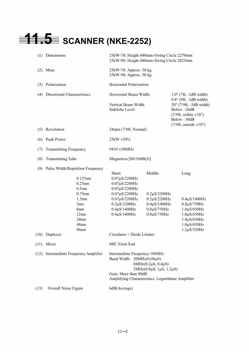
11─5
11.5 SCANNER (NKE-2252)
(1) Dimensions 25kW-7ft: Height 440mm�Swing Circle 2270mm 25kW-9ft: Height 440mm�Swing Circle 2825mm (2) Mass 25kW-7ft: Approx. 50 kg 25kW-9ft: Approx. 50 kg (3) Polarization Horizontal Polarization (4) Directional Characteristics Horizontal Beam Width: 1.0� (7ft, -3dB width) 0.8� (9ft, -3dB width) Vertical Beam Width 20� (7/9ft, -3dB width) Sidelobe Level: Below –26dB (7/9ft, within �10�) Below –30dB (7/9ft, outside �10�) (5) Revolution 24rpm (7/9ft, Normal) (6) Peak Power 25kW �50% (7) Transmitting Frequency 9410 �30MHz (8) Transmitting Tube Magnetron [M1568B(J)] (9) Pulse Width/Repetition Frequency
Short Middle Long 0.125nm 0.07�S/2200Hz 0.25nm 0.07�S/2200Hz 0.5nm 0.07�S/2200Hz 0.75nm 0.07�S/2200Hz 0.2�S/2200Hz 1.5nm 0.07�S/2200Hz 0.2�S/2200Hz 0.4�S/1400Hz 3nm 0.2�S/2200Hz 0.4�S/1400Hz 0.8�S/750Hz 6nm 0.4�S/1400Hz 0.8�S/750Hz 1.0�S/650Hz 12nm 0.4�S/1400Hz 0.8�S/750Hz 1.0�S/650Hz 24nm 1.0�S/650Hz 48nm 1.0�S/650Hz 96nm 1.2�S/520Hz
(10) Duplexer Circulator + Diode Limiter (11) Mixer MIC Front End (12) Intermediate Frequency Amplifier Intermediate Frequency: 60MHz Band Width: 20MHz(0.08�S) 6MHz(0.2�S, 0.4�S) 3MHz(0.8�S, 1�S, 1.2�S) Gain: More than 90dB Amplifying Characteristics: Logarithmic Amplifier (13) Overall Noise Figure 6dB(Average)
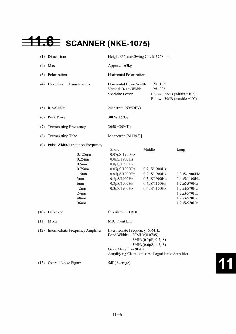
11─6
11
11.6 SCANNER (NKE-1075)
(1) Dimensions Height 837mm�Swing Circle 3758mm (2) Mass Approx. 163kg (3) Polarization Horizontal Polarization (4) Directional Characteristics Horizontal Beam Width 12ft: 1.9�
Vertical Beam Width 12ft: 30� Sidelobe Level: Below –26dB (within �10�) Below –30dB (outside �10�) (5) Revolution 24/21rpm (60/50Hz) (6) Peak Power 30kW �50% (7) Transmitting Frequency 3050 �30MHz (8) Transmitting Tube Magnetron [M1302]] (9) Pulse Width/Repetition Frequency
Short Middle Long 0.125nm 0.07�S/1900Hz 0.25nm 0.0�S/1900Hz 0.5nm 0.0�S/1900Hz 0.75nm 0.07�S/1900Hz 0.2�S/1900Hz 1.5nm 0.07�S/1900Hz 0.2�S/1900Hz 0.3�S/1900Hz 3nm 0.2�S/1900Hz 0.3�S/1900Hz 0.6�S/1100Hz 6nm 0.3�S/1900Hz 0.6�S/1100Hz 1.2�S/570Hz 12nm 0.3�S/1900Hz 0.6�S/1100Hz 1.2�S/570Hz 24nm 1.2�S/570Hz 48nm 1.2�S/570Hz 96nm 1.2�S/570Hz
(10) Duplexer Circulator + TRHPL (11) Mixer MIC Front End (12) Intermediate Frequency Amplifier Intermediate Frequency: 60MHz Band Width: 20MHz(0.07uS) 6MHz(0.2�S, 0.3�S) 3MHz(0.6�S, 1.2�S) Gain: More than 90dB Amplifying Characteristics: Logarithmic Amplifier (13) Overall Noise Figure 5dB(Average)
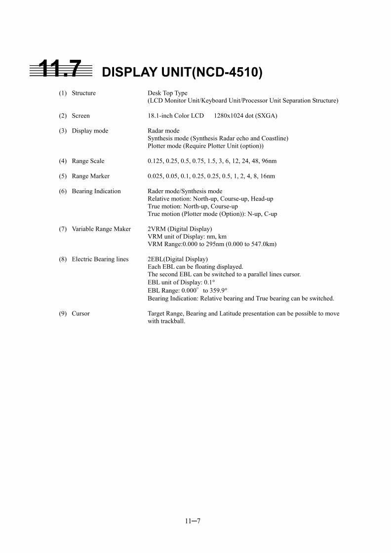
11─7
11.7 DISPLAY UNIT(NCD-4510)
(1) Structure Desk Top Type (LCD Monitor Unit/Keyboard Unit/Processor Unit Separation Structure)
(2) Screen 18.1-inch Color LCD 1280x1024 dot (SXGA) (3) Display mode Radar mode Synthesis mode (Synthesis Radar echo and Coastline) Plotter mode (Require Plotter Unit (option)) (4) Range Scale 0.125, 0.25, 0.5, 0.75, 1.5, 3, 6, 12, 24, 48, 96nm (5) Range Marker 0.025, 0.05, 0.1, 0.25, 0.25, 0.5, 1, 2, 4, 8, 16nm (6) Bearing Indication Rader mode/Synthesis mode Relative motion: North-up, Course-up, Head-up True motion: North-up, Course-up True motion (Plotter mode (Option)): N-up, C-up (7) Variable Range Maker 2VRM (Digital Display) VRM unit of Display: nm, km VRM Range:0.000 to 295nm (0.000 to 547.0km) (8) Electric Bearing lines 2EBL(Digital Display) Each EBL can be floating displayed. The second EBL can be switched to a parallel lines cursor. EBL unit of Display: 0.1� EBL Range: 0.000°to 359.9� Bearing Indication: Relative bearing and True bearing can be switched. (9) Cursor Target Range, Bearing and Latitude presentation can be possible to move
with trackball.
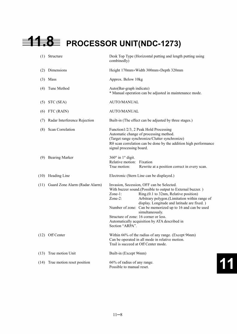
11─8
11
11.8 PROCESSOR UNIT(NDC-1273) (1) Structure Desk Top Type (Horizontal putting and length putting using
combinedly) (2) Dimensions Height 170mm�Width 300mm�Depth 320mm (3) Mass Approx. Below 10kg (4) Tune Method Auto(Bar-graph indicate) * Manual operation can be adjusted in maintenance mode. (5) STC (SEA) AUTO/MANUAL (6) FTC (RAIN) AUTO/MANUAL (7) Radar Interference Rejection Built-in (The effect can be adjusted by three stages.) (8) Scan Correlation Function1/2/3, 2 Peak Hold Processing Automatic change of processing method. (Target range synchronize/Clutter synchronize) R� scan correlation can be done by the addition high performance
signal processing board. (9) Bearing Marker 360� in 1� digit. Relative motion: Fixation True motion: Rewrite at a position correct in every scan. (10) Heading Line Electronic (Stern Line can be displayed.) (11) Guard Zone Alarm (Radar Alarm) Invasion, Secession, OFF can be Selected. With buzzer sound.(Possible to output to External buzzer. ) Zone-1: Ring.(0.1 to 32nm, Relative position) Zone-2: Arbitrary polygon.(Limitation within range of
display. Longitude and latitude are fixed. ) Number of zone: Can be memorized up to 16 and can be used
simultaneously. Structure of zone: 16 corner or less. Automatically acquisition by ATA described in Section “ARPA”. (12) Off Center Within 66% of the radius of any range. (Except 96nm) Can be operated in all mode in relative motion. Trail is succeed at Off Center mode. (13) True motion Unit Built-in (Except 96nm) (14) True motion reset position 66% of radius of any range. Possible to manual reset.
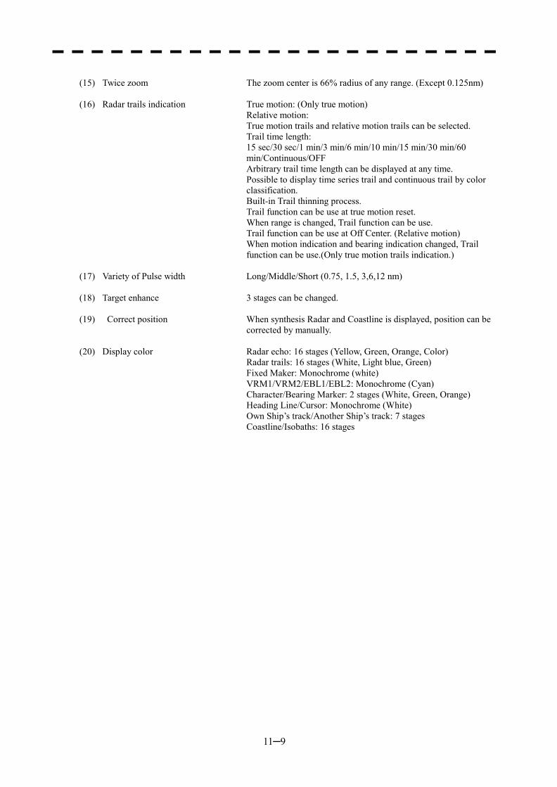
11─9
(15) Twice zoom The zoom center is 66% radius of any range. (Except 0.125nm) (16) Radar trails indication True motion: (Only true motion) Relative motion:
True motion trails and relative motion trails can be selected. Trail time length:
15 sec/30 sec/1 min/3 min/6 min/10 min/15 min/30 min/60 min/Continuous/OFF
Arbitrary trail time length can be displayed at any time. Possible to display time series trail and continuous trail by color
classification. Built-in Trail thinning process. Trail function can be use at true motion reset. When range is changed, Trail function can be use. Trail function can be use at Off Center. (Relative motion) When motion indication and bearing indication changed, Trail
function can be use.(Only true motion trails indication.) (17) Variety of Pulse width Long/Middle/Short (0.75, 1.5, 3,6,12 nm) (18) Target enhance 3 stages can be changed. (19) Correct position When synthesis Radar and Coastline is displayed, position can be
corrected by manually. (20) Display color Radar echo: 16 stages (Yellow, Green, Orange, Color) Radar trails: 16 stages (White, Light blue, Green) Fixed Maker: Monochrome (white) VRM1/VRM2/EBL1/EBL2: Monochrome (Cyan) Character/Bearing Marker: 2 stages (White, Green, Orange) Heading Line/Cursor: Monochrome (White) Own Ship’s track/Another Ship’s track: 7 stages Coastline/Isobaths: 16 stages
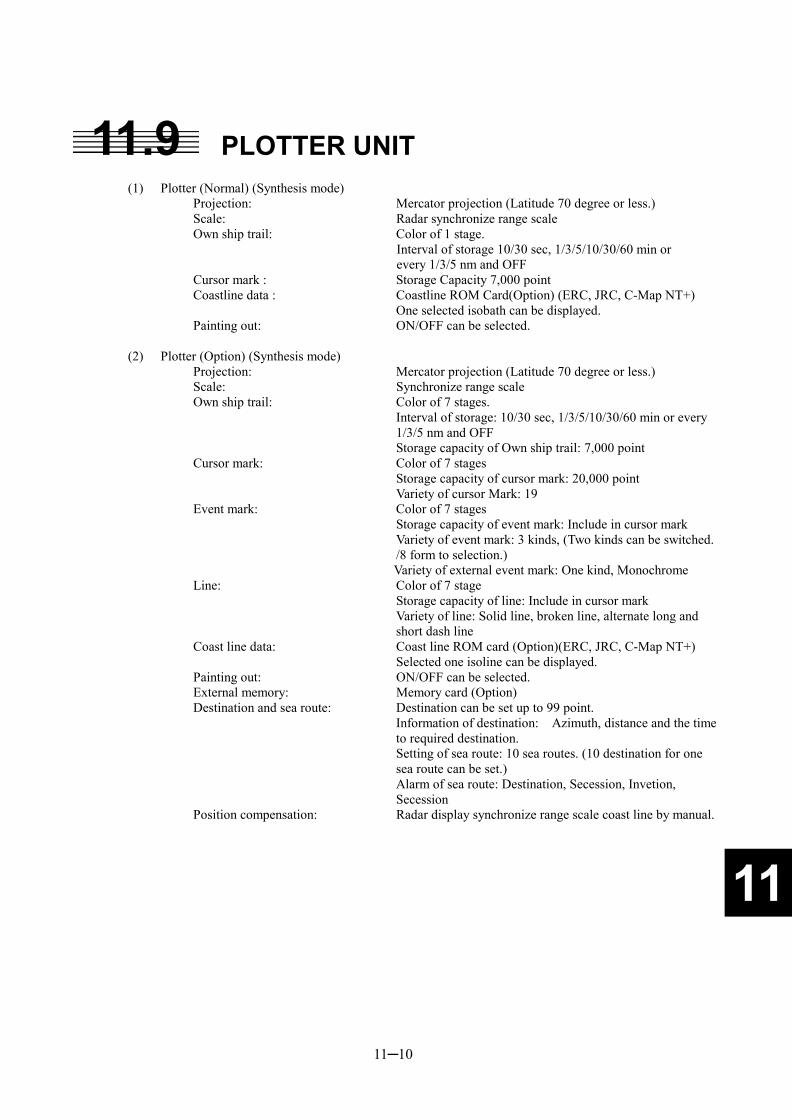
11─10
11
11.9 PLOTTER UNIT
(1) Plotter (Normal) (Synthesis mode) Projection: Mercator projection (Latitude 70 degree or less.) Scale: Radar synchronize range scale Own ship trail: Color of 1 stage.
Interval of storage 10/30 sec, 1/3/5/10/30/60 min or every 1/3/5 nm and OFF
Cursor mark : Storage Capacity 7,000 point Coastline data : Coastline ROM Card(Option) (ERC, JRC, C-Map NT+) One selected isobath can be displayed. Painting out: ON/OFF can be selected.
(2) Plotter (Option) (Synthesis mode)
Projection: Mercator projection (Latitude 70 degree or less.) Scale: Synchronize range scale Own ship trail: Color of 7 stages. Interval of storage: 10/30 sec, 1/3/5/10/30/60 min or every
1/3/5 nm and OFF Storage capacity of Own ship trail: 7,000 point Cursor mark: Color of 7 stages Storage capacity of cursor mark: 20,000 point Variety of cursor Mark: 19 Event mark: Color of 7 stages Storage capacity of event mark: Include in cursor mark Variety of event mark: 3 kinds, (Two kinds can be switched.
/8 form to selection.) Variety of external event mark: One kind, Monochrome Line: Color of 7 stage Storage capacity of line: Include in cursor mark Variety of line: Solid line, broken line, alternate long and
short dash line Coast line data: Coast line ROM card (Option)(ERC, JRC, C-Map NT+) Selected one isoline can be displayed. Painting out: ON/OFF can be selected. External memory: Memory card (Option) Destination and sea route: Destination can be set up to 99 point. Information of destination: Azimuth, distance and the time
to required destination. Setting of sea route: 10 sea routes. (10 destination for one
sea route can be set.) Alarm of sea route: Destination, Secession, Invetion,
Secession Position compensation: Radar display synchronize range scale coast line by manual.
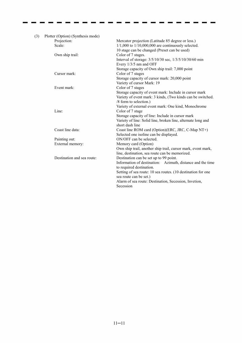
11─11
(3) Plotter (Option) (Synthesis mode)
Projection: Mercator projection (Latitude 85 degree or less.) Scale: 1/1,000 to 1/10,000,000 are continuously selected. 10 stage can be changed (Preset can be used) Own ship trail: Color of 7 stages. Interval of storage: 3/5/10/30 sec, 1/3/5/10/30/60 min Every 1/3/5 nm and OFF Storage capacity of Own ship trail: 7,000 point Cursor mark: Color of 7 stages Storage capacity of cursor mark: 20,000 point Variety of cursor Mark: 19 Event mark: Color of 7 stages Storage capacity of event mark: Include in cursor mark Variety of event mark: 3 kinds, (Two kinds can be switched.
/8 form to selection.) Variety of external event mark: One kind, Monochrome Line: Color of 7 stage Storage capacity of line: Include in cursor mark Variety of line: Solid line, broken line, alternate long and
short dash line Coast line data: Coast line ROM card (Option)(ERC, JRC, C-Map NT+) Selected one isoline can be displayed. Painting out: ON/OFF can be selected. External memory: Memory card (Option) Own ship trail, another ship trail, cursor mark, event mark,
line, destination, sea route can be memorized. Destination and sea route: Destination can be set up to 99 point. Information of destination: Azimuth, distance and the time
to required destination. Setting of sea route: 10 sea routes. (10 destination for one
sea route can be set.) Alarm of sea route: Destination, Secession, Invetion,
Secession
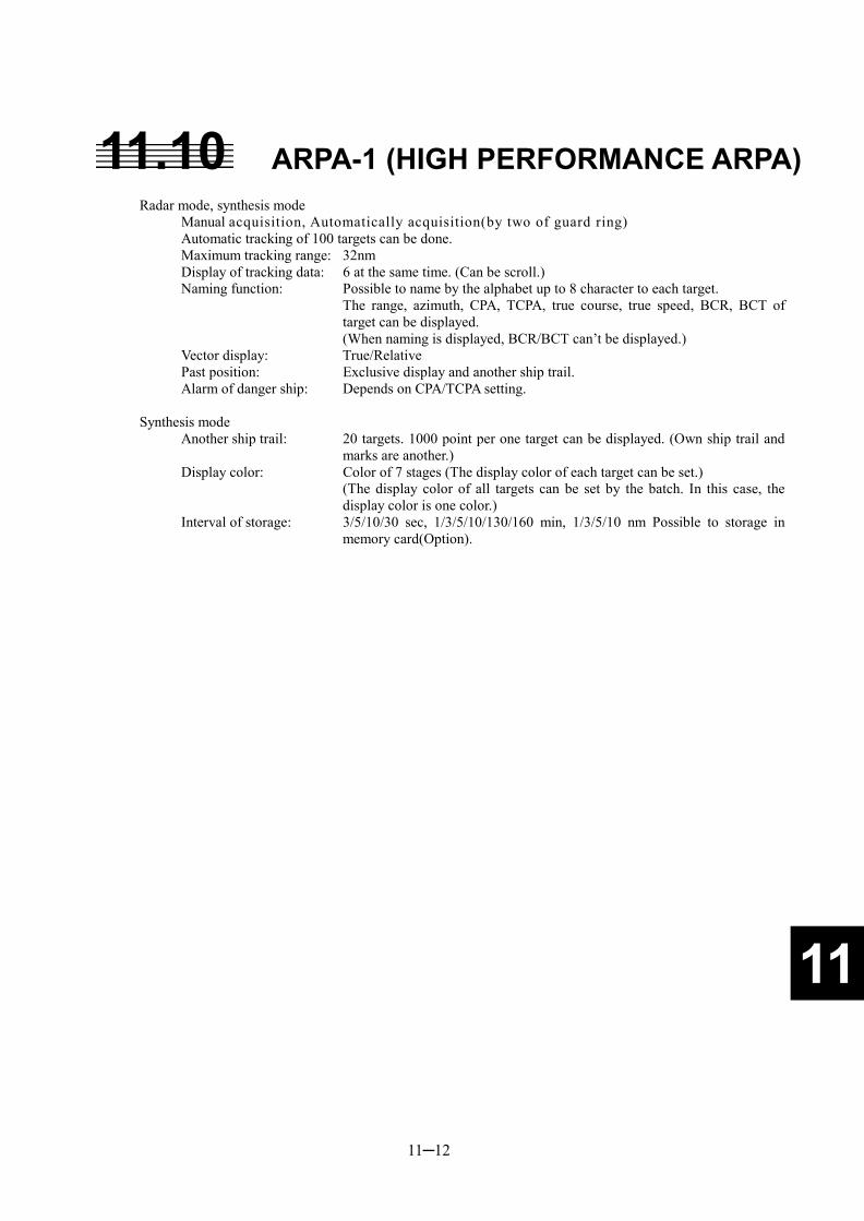
11─12
11
11.10 ARPA-1 (HIGH PERFORMANCE ARPA) Radar mode, synthesis mode
Manual acquisition, Automatically acquisition(by two of guard ring) Automatic tracking of 100 targets can be done. Maximum tracking range: 32nm Display of tracking data: 6 at the same time. (Can be scroll.) Naming function: Possible to name by the alphabet up to 8 character to each target. The range, azimuth, CPA, TCPA, true course, true speed, BCR, BCT of
target can be displayed. (When naming is displayed, BCR/BCT can’t be displayed.) Vector display: True/Relative Past position: Exclusive display and another ship trail. Alarm of danger ship: Depends on CPA/TCPA setting.
Synthesis mode Another ship trail: 20 targets. 1000 point per one target can be displayed. (Own ship trail and
marks are another.) Display color: Color of 7 stages (The display color of each target can be set.) (The display color of all targets can be set by the batch. In this case, the
display color is one color.) Interval of storage: 3/5/10/30 sec, 1/3/5/10/130/160 min, 1/3/5/10 nm Possible to storage in
memory card(Option).
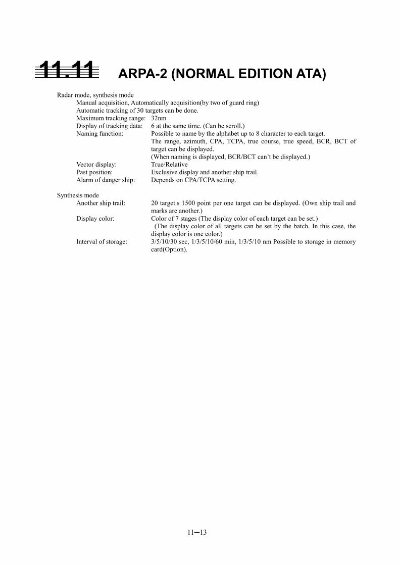
11─13
11.11 ARPA-2 (NORMAL EDITION ATA) Radar mode, synthesis mode
Manual acquisition, Automatically acquisition(by two of guard ring) Automatic tracking of 30 targets can be done. Maximum tracking range: 32nm Display of tracking data: 6 at the same time. (Can be scroll.) Naming function: Possible to name by the alphabet up to 8 character to each target. The range, azimuth, CPA, TCPA, true course, true speed, BCR, BCT of
target can be displayed. (When naming is displayed, BCR/BCT can’t be displayed.) Vector display: True/Relative Past position: Exclusive display and another ship trail. Alarm of danger ship: Depends on CPA/TCPA setting.
Synthesis mode Another ship trail: 20 target.s 1500 point per one target can be displayed. (Own ship trail and
marks are another.) Display color: Color of 7 stages (The display color of each target can be set.) (The display color of all targets can be set by the batch. In this case, the
display color is one color.) Interval of storage: 3/5/10/30 sec, 1/3/5/10/60 min, 1/3/5/10 nm Possible to storage in memory
card(Option).
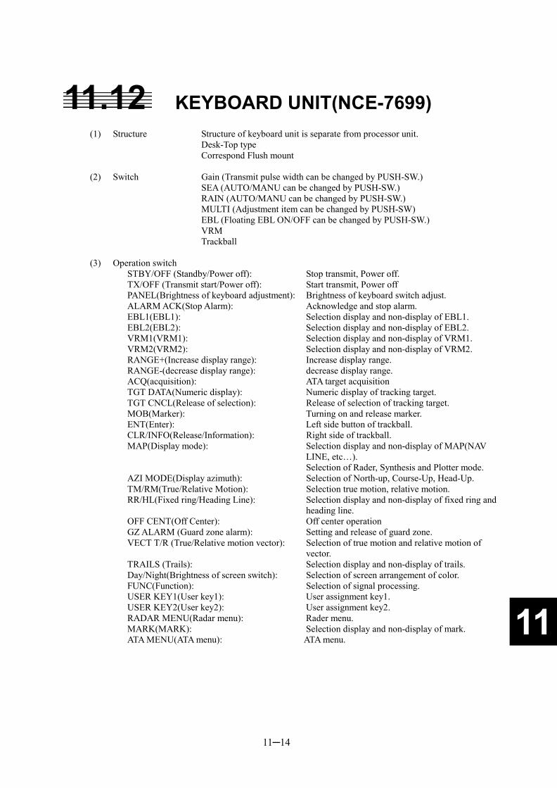
11─14
11
11.12 KEYBOARD UNIT(NCE-7699)
(1) Structure Structure of keyboard unit is separate from processor unit. Desk-Top type Correspond Flush mount (2) Switch Gain (Transmit pulse width can be changed by PUSH-SW.) SEA (AUTO/MANU can be changed by PUSH-SW.) RAIN (AUTO/MANU can be changed by PUSH-SW.) MULTI (Adjustment item can be changed by PUSH-SW) EBL (Floating EBL ON/OFF can be changed by PUSH-SW.) VRM Trackball (3) Operation switch
STBY/OFF (Standby/Power off): Stop transmit, Power off. TX/OFF (Transmit start/Power off): Start transmit, Power off PANEL(Brightness of keyboard adjustment): Brightness of keyboard switch adjust. ALARM ACK(Stop Alarm): Acknowledge and stop alarm. EBL1(EBL1): Selection display and non-display of EBL1. EBL2(EBL2): Selection display and non-display of EBL2. VRM1(VRM1): Selection display and non-display of VRM1. VRM2(VRM2): Selection display and non-display of VRM2. RANGE+(Increase display range): Increase display range. RANGE-(decrease display range): decrease display range. ACQ(acquisition): ATA target acquisition TGT DATA(Numeric display): Numeric display of tracking target. TGT CNCL(Release of selection): Release of selection of tracking target. MOB(Marker): Turning on and release marker. ENT(Enter): Left side button of trackball. CLR/INFO(Release/Information): Right side of trackball. MAP(Display mode): Selection display and non-display of MAP(NAV
LINE, etc…). Selection of Rader, Synthesis and Plotter mode. AZI MODE(Display azimuth): Selection of North-up, Course-Up, Head-Up. TM/RM(True/Relative Motion): Selection true motion, relative motion. RR/HL(Fixed ring/Heading Line): Selection display and non-display of fixed ring and
heading line. OFF CENT(Off Center): Off center operation GZ ALARM (Guard zone alarm): Setting and release of guard zone. VECT T/R (True/Relative motion vector): Selection of true motion and relative motion of
vector. TRAILS (Trails): Selection display and non-display of trails. Day/Night(Brightness of screen switch): Selection of screen arrangement of color. FUNC(Function): Selection of signal processing. USER KEY1(User key1): User assignment key1. USER KEY2(User key2): User assignment key2. RADAR MENU(Radar menu): Rader menu. MARK(MARK): Selection display and non-display of mark. ATA MENU(ATA menu): ATA menu.
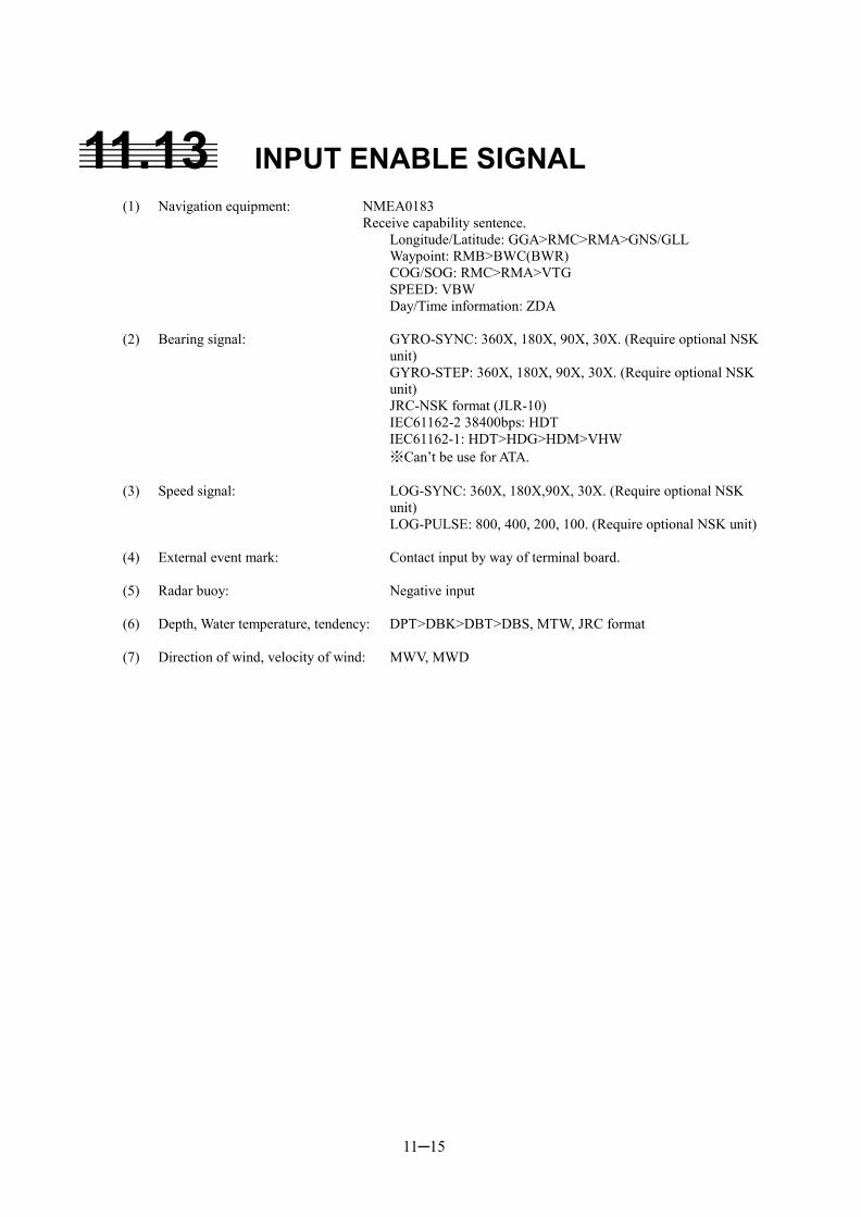
11─15
11.13 INPUT ENABLE SIGNAL
(1) Navigation equipment: NMEA0183 Receive capability sentence. Longitude/Latitude: GGA>RMC>RMA>GNS/GLL Waypoint: RMB>BWC(BWR) COG/SOG: RMC>RMA>VTG SPEED: VBW Day/Time information: ZDA (2) Bearing signal: GYRO-SYNC: 360X, 180X, 90X, 30X. (Require optional NSK
unit) GYRO-STEP: 360X, 180X, 90X, 30X. (Require optional NSK
unit) JRC-NSK format (JLR-10) IEC61162-2 38400bps: HDT IEC61162-1: HDT>HDG>HDM>VHW ※Can’t be use for ATA. (3) Speed signal: LOG-SYNC: 360X, 180X,90X, 30X. (Require optional NSK
unit) LOG-PULSE: 800, 400, 200, 100. (Require optional NSK unit) (4) External event mark: Contact input by way of terminal board. (5) Radar buoy: Negative input (6) Depth, Water temperature, tendency: DPT>DBK>DBT>DBS, MTW, JRC format (7) Direction of wind, velocity of wind: MWV, MWD
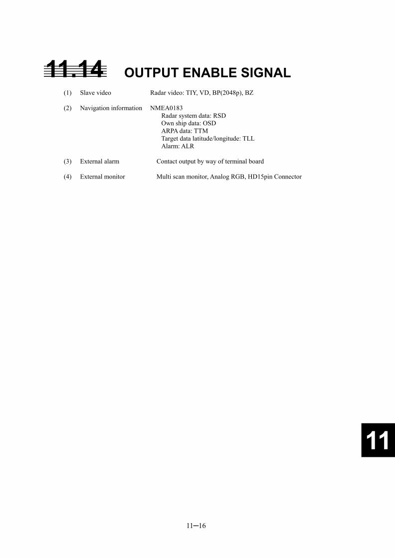
11─16
11
11.14 OUTPUT ENABLE SIGNAL
(1) Slave video Radar video: TIY, VD, BP(2048p), BZ (2) Navigation information NMEA0183 Radar system data: RSD Own ship data: OSD ARPA data: TTM Target data latitude/longitude: TLL Alarm: ALR (3) External alarm Contact output by way of terminal board (4) External monitor Multi scan monitor, Analog RGB, HD15pin Connector
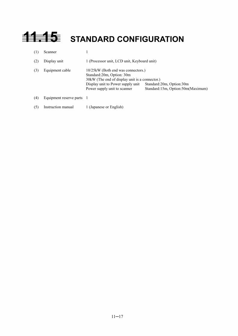
11─17
11.15 STANDARD CONFIGURATION
(1) Scanner 1 (2) Display unit 1 (Processor unit, LCD unit, Keyboard unit) (3) Equipment cable 10/25kW (Both end was connectors.) Standard:20m, Option: 30m 30kW (The end of display unit is a connector.) Display unit to Power supply unit Standard:20m, Option:30m Power supply unit to scanner Standard:15m, Option:50m(Maximum) (4) Equipment reserve parts 1 (5) Instruction manual 1 (Japanese or English)
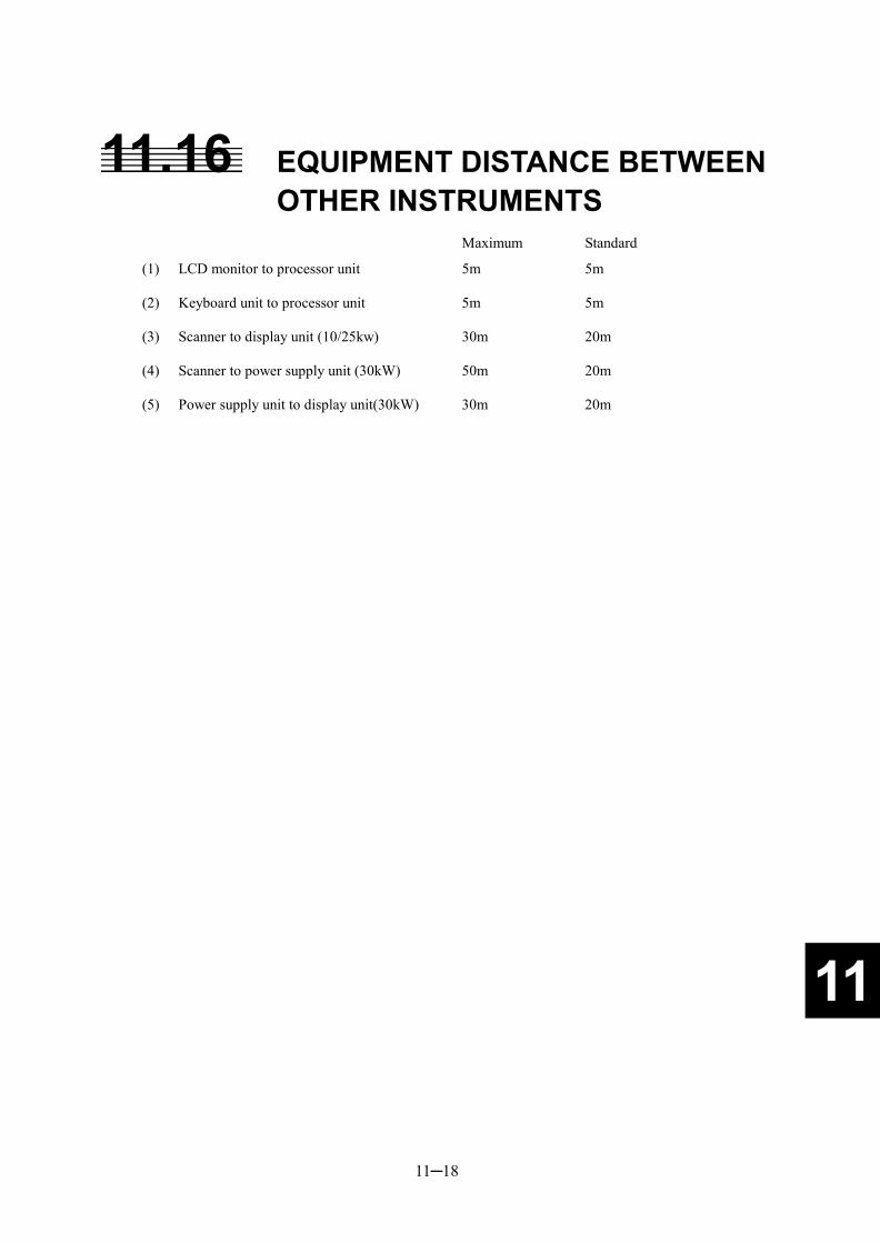
11─18
11
11.16 EQUIPMENT DISTANCE BETWEEN OTHER INSTRUMENTS
Maximum Standard
(1) LCD monitor to processor unit 5m 5m (2) Keyboard unit to processor unit 5m 5m (3) Scanner to display unit (10/25kw) 30m 20m (4) Scanner to power supply unit (30kW) 50m 20m (5) Power supply unit to display unit(30kW) 30m 20m
11─19
11.17 OTHERS (OPTION)
� High performance ARPA unit (Built-in) � Normal edition ATA unit (Built-in) � NSK unit (Built-in) � Plotter (Built-in) � AIS interface (Built-in) � Coast line ROM card � Memory card � Inter Switch
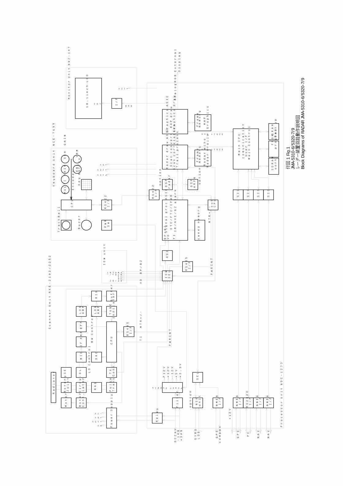
MIC
IF
AMP
BPF
LOG
AMP
LOG
AMP
MIX
TUNE
indicater
DAC
LO
Control
BW
Control
CPU
Power
Supply
HV
+15V
+8V
-7V
Filter
PowerSupply
P12V
+12V
-12V
+5V
+3.3V
buffer
ISW
SEL
TI
MTR+/-
VD
BP/BZ
Relay
BP/BZVDTIMTR+/-PWRCNT
ADC
ISW
unit
BP/BZ
VD
TI
Signal
proc
ASIC
STC/FTC/CFAR
IR/AVE/GZ
alarm
DSP
radar
DSP
ARPA
option
option
sweep
memory
Radar
draw
ASIC
Scan
convert
Scan
correlation
Trail
process
Radar
echo
Radar
trails
Frame
sub
CPU
MULTI
RAIN
SEA
GAIN
EBL
VRM
Encoder
CPU
TrackBall
Buzer
Key
matrix
RS422
I/F
PWR
SW
RS485
I/F
RS485
I/F
P12V
+12V
+5V
MTR+/-
PWRCNT
PWRCNT
NSK
unit
option
NMEA
I/F
SEL
RS232C
I/F
RS422
I/F
Main
CPU
comunication
User
I/F
Main
Control
SDRAM
FROM
work
program
+12V
LDIRGBI
/F
SIO
SIO
NMEA
I/F
18.1inch
LCD
AnalogRGB
DC24V
-10%
GYRO
LOG
GPS
compas
GPS
+12V
PC
32bitbus
Monitor
Unit
NWZ-147
Keyboard
Unit
NCE-7699
Scanner
Unit
NKE-2102/2252
Processor
Unit
NDC-1273
External
Display
NMEA
I/F
SIO
SIO
NMEA
I/F
NAV
NAV
SRAM
Back
up
memory
Graphics
ASIC
MAP
draw
Graphics
draw
MAP
Graphics
Frame
memory
32bitbus
+30%
Radiater
Rotary
Joint
Circu-
later
DL
MAG
Pulse
Trans
SE
Motor
Motor
Cont.
TX
Cont.
付図
1Fi
g.1
JMA-
5310
-6/5
320-
7/9
レー
ダー
装置
回路
動作
説明
図
Bloc
k D
iagr
ams
of R
ADAR
JM
A-53
10-6
/532
0-7/
9
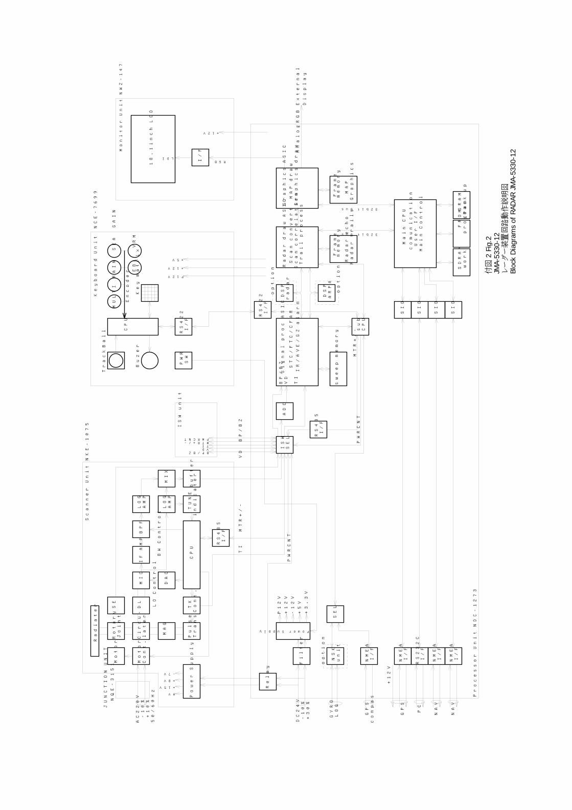
Radiater
Rotary
Joint
Circu-
later
DL
MIC
MAG
Pulse
Trans
SE
Motor
Motor
Cont.
IF
AMP
BPF
LOG
AMP
LOG
AMP
MIX
TUNE
indicater
DAC
TX
Cont.
LO
Control
BW
Control
CPU
Power
Supply
HV
+15V
+8V
-7V
Filter
PowerSupply
P12V
+12V
-12V
+5V
+3.3V
buffer
ISW
SEL
TI
MTR+/-
VD
BP/BZ
Relay
BP/BZVDTIMTR+/-PWRCNT
ADC
ISW
unit
BP/BZ
VD
TI
Signal
proc
ASIC
STC/FTC/CFAR
IR/AVE/GZ
alarm
DSP
radar
DSP
ARPA
option
option
sweep
memory
Radar
draw
ASIC
Scan
convert
Scan
correlation
Trail
process
Radar
echo
Radar
trails
Frame
sub
CPU
MULTI
RAIN
SEA
GAIN
EBL
VRM
Encoder
CPU
TrackBall
Buzer
Key
matrix
RS422
I/F
PWR
SW
RS485
I/F
RS485
I/F
P12V
+12V
+5V
MTR+/-
PWRCNT
PWRCNT
NSK
unit
option
NMEA
I/F
SEL
RS232C
I/F
RS422
I/F
Main
CPU
comunication
User
I/F
Main
Control
SDRAM
FROM
work
program
+12V
LDIRGBI
/F
SIO
SIO
NMEA
I/F
18.1inch
LCD
AnalogRGB
DC24V
-10%
GYRO
LOG
GPS
compas
GPS
+12V
PC
32bitbus
Monitor
Unit
NWZ-147
Keyboard
Unit
NCE-7699
Scanner
Unit
NKE-1075
Processor
Unit
NDC-1273
External
Display
NMEA
I/F
SIO
SIO
NMEA
I/F
NAV
NAV
SRAM
Back
up
memory
Graphics
ASIC
MAP
draw
Graphics
draw
MAP
Graphics
Frame
memory
32bitbus
+30%
AC220V
-10%
+10%
50/60HzJUNCTION
UNIT
NQE-3151
付図
2Fi
g.2
JMA-
5330
-12
レー
ダー
装置
回路
動作
説明
図
Bloc
k D
iagr
ams
of R
ADAR
JM
A-53
30-1
2
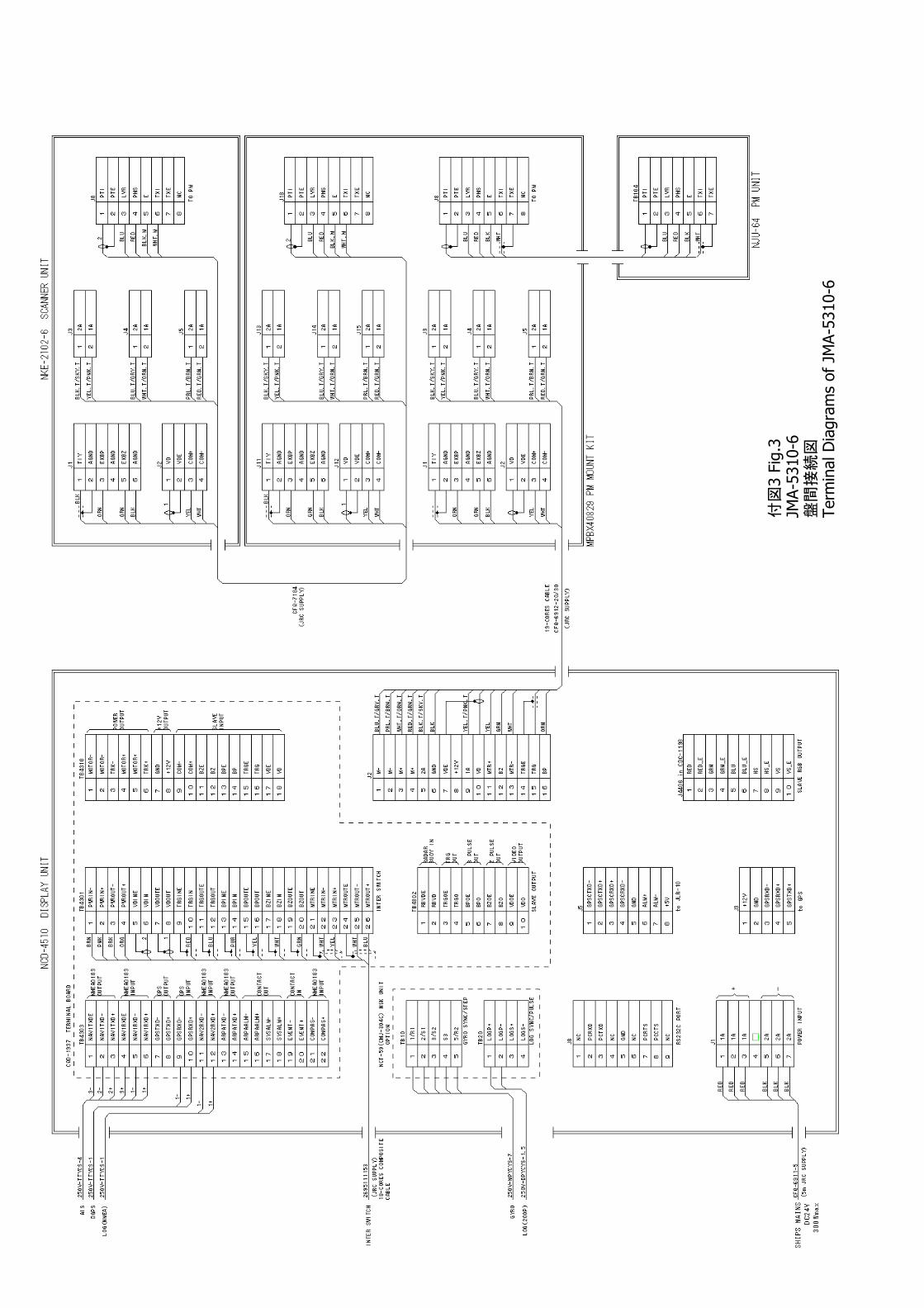
3 Fi
g.3
付図
JMA-
5310
-6盤
間接
続図
Term
inal
Dia
gram
s of
JM
A-53
10-6
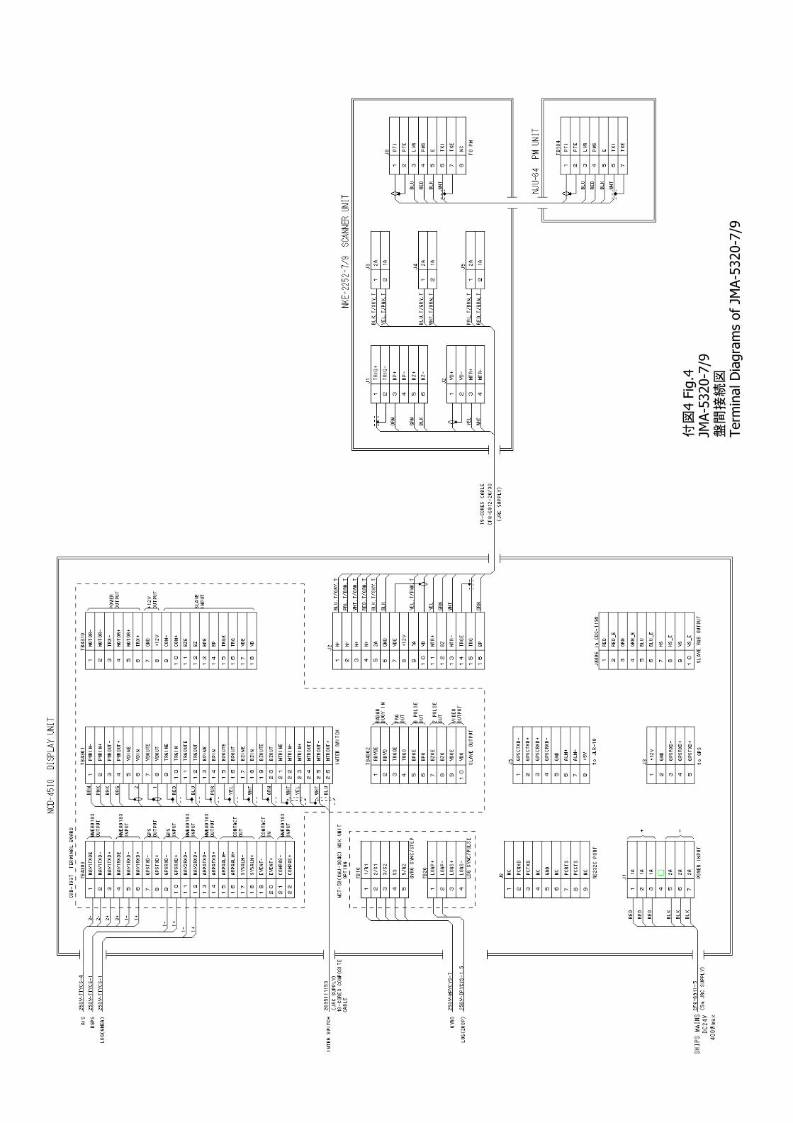
4 Fi
g.4
付図
JMA-
5320
-7/9
盤間
接続
図Te
rmin
al D
iagr
ams
of J
MA-
5320
-7/9
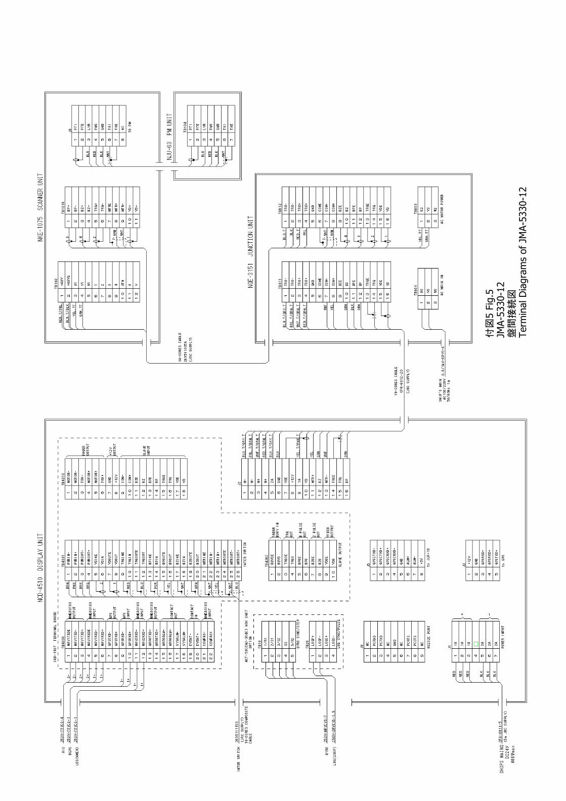
5 Fi
g.5
付図
JMA-
5330
-12
盤間
接続
図Te
rmin
al D
iagr
ams
of J
MA-
5330
-12
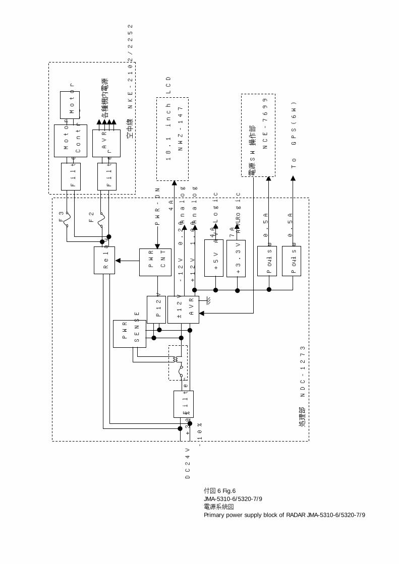
Filter
P12V
±12V
AVR
+5V AVR
+3.3V AVR
Poly-sw
PWR
CNT
Relay
Filter
Motor
Control
Motor
AVR
Filter
F2
F3
PWR
SENSE
PWR-ON
Poly-sw
-12V 0.2A
+12V 1.0A
Analog
Analog
4A
7A
Logic
Logic
4A
18.1 inch LCD
NWZ-147
操作
部
NCE-7699
To
GPS(6W)
電源
SW
各種
機内電
源
空中線 NKE-2102/2252
処理
部 NDC-1273
DC24V
+30%
-10%
0.5A
0.5A
付図 6 Fig.6 JMA-5310-6/5320-7/9 電源系統図 Primary power supply block of RADAR JMA-5310-6/5320-7/9
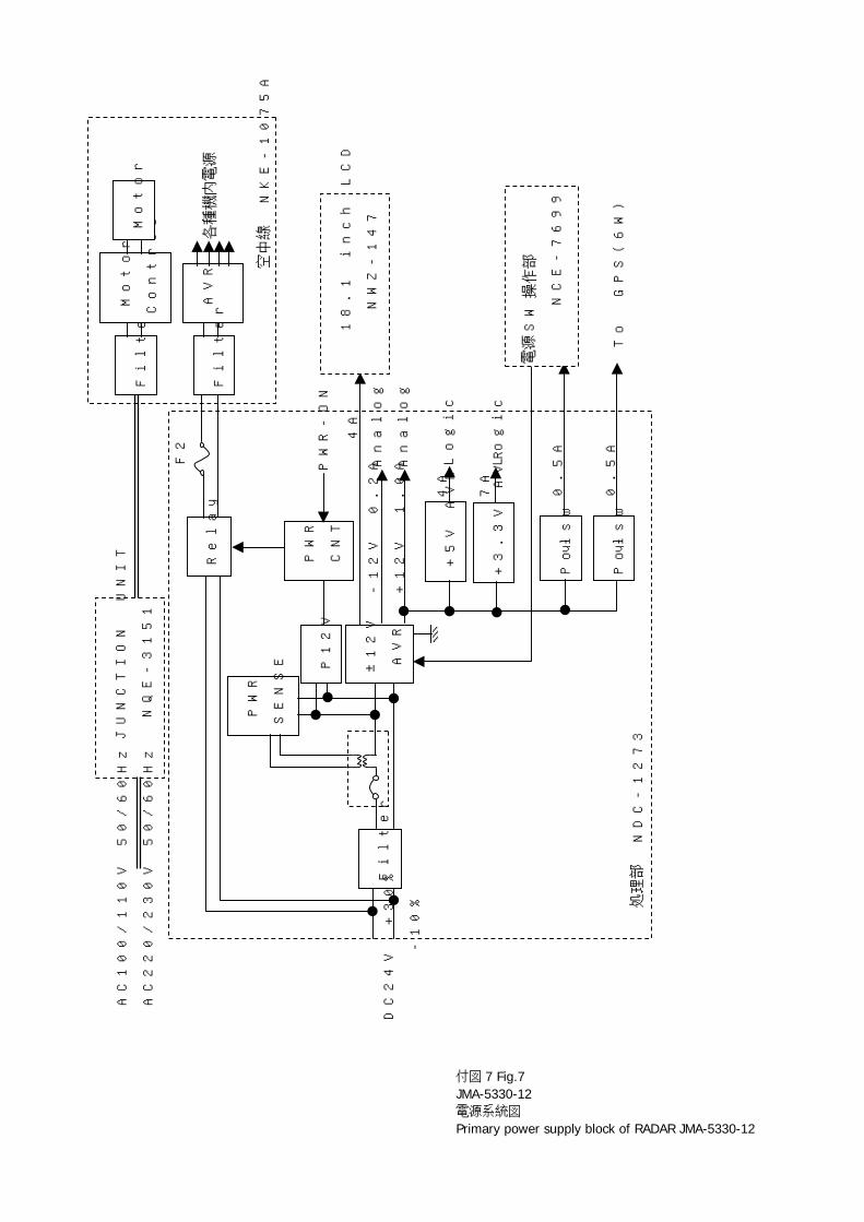
Filter
P12V
±12V
AVR
+5V AVR
+3.3V AVR
Poly-sw
PWR
CNT
Relay
Filter
Motor
Control
Motor
AVR
Filter
F2
PWR
SENSE
PWR-ON
Poly-sw
-12V 0.2A
+12V 1.0A
Analog
Analog
4A
7A
Logic
Logic
4A
18.1 inch LCD
NWZ-147
操作
部
NCE-7699
To
GPS(6W)
電源
SW
各種
機内電
源
空中
線 NKE-1075A
処理
部 ND
C-1273
DC24V
+30%
-10%
0.5A
0.5A
JUNCTION
UNIT
NQE-3151
AC100/110V 50/60Hz
AC220/230V 50/60Hz
付図 7 Fig.7 JMA-5330-12 電源系統図 Primary power supply block of RADAR JMA-5330-12
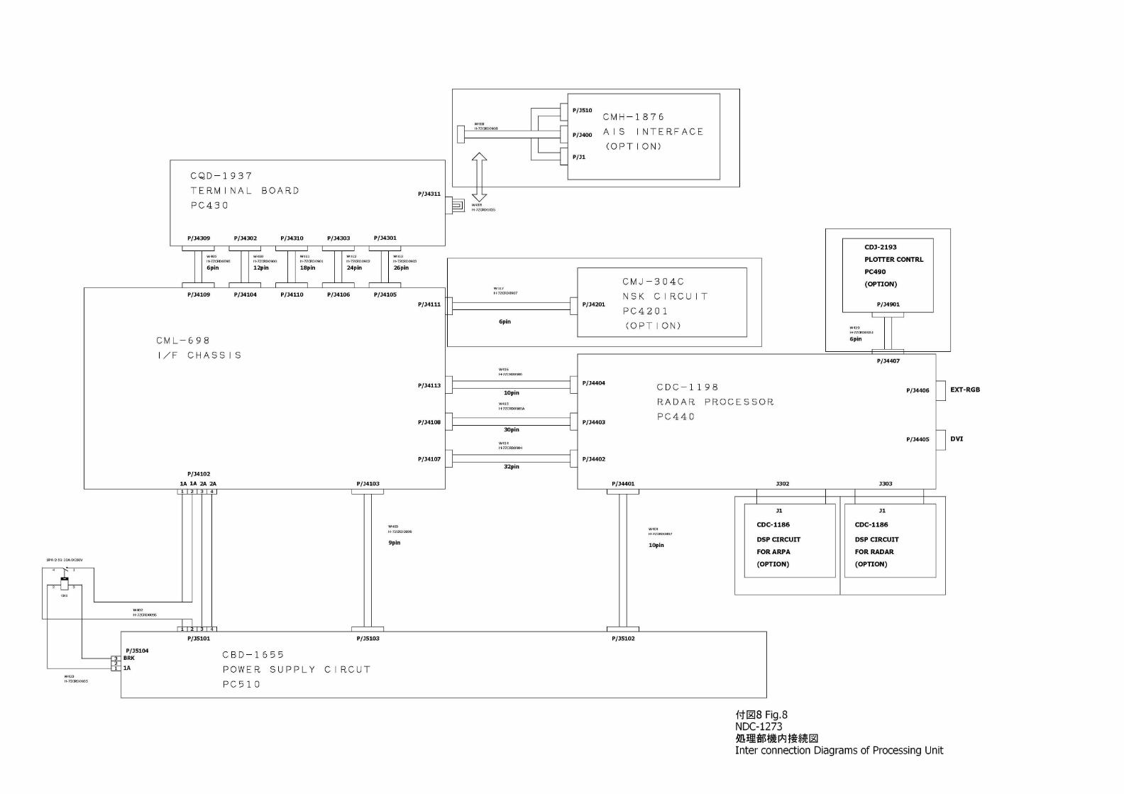
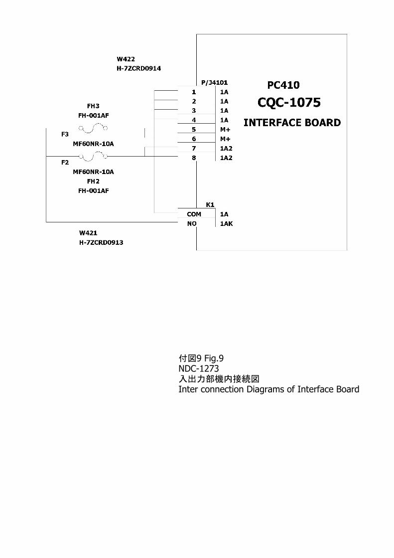
9 Fig.9付図NDC-1273入出力部機内接続図Inter connection Diagrams of Interface Board
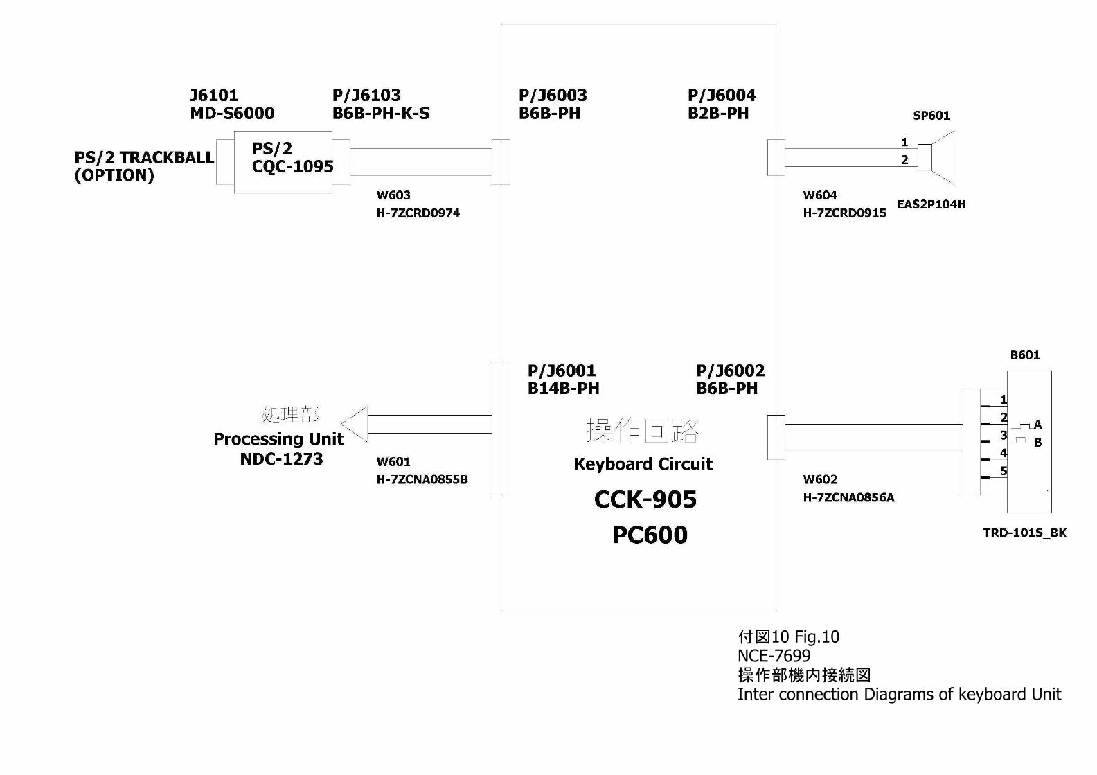
10 Fig.10付図NCE-7699操作部機内接続図Inter connection Diagrams of keyboard Unit
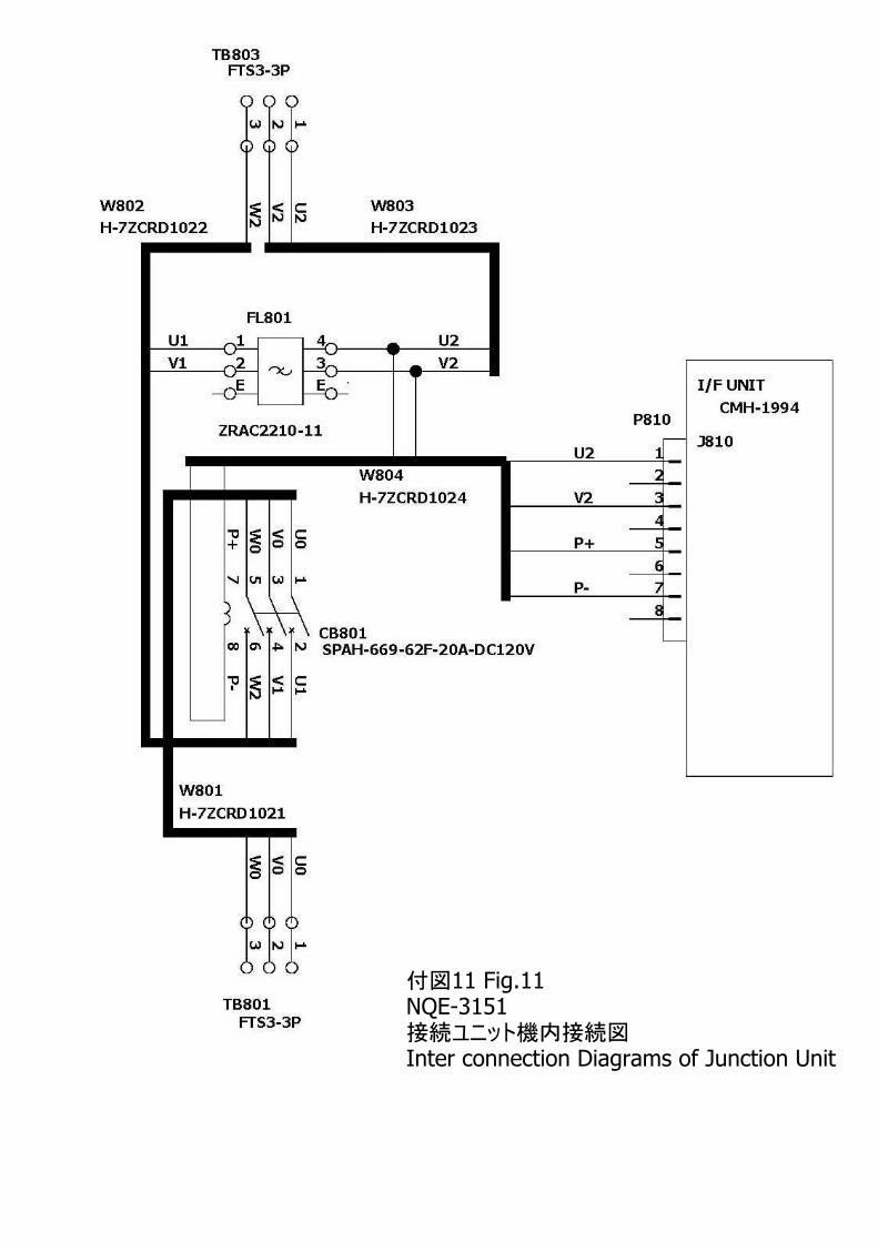
11 Fig.11付図NQE-3151接続ユニット機内接続図Inter connection Diagrams of Junction Unit
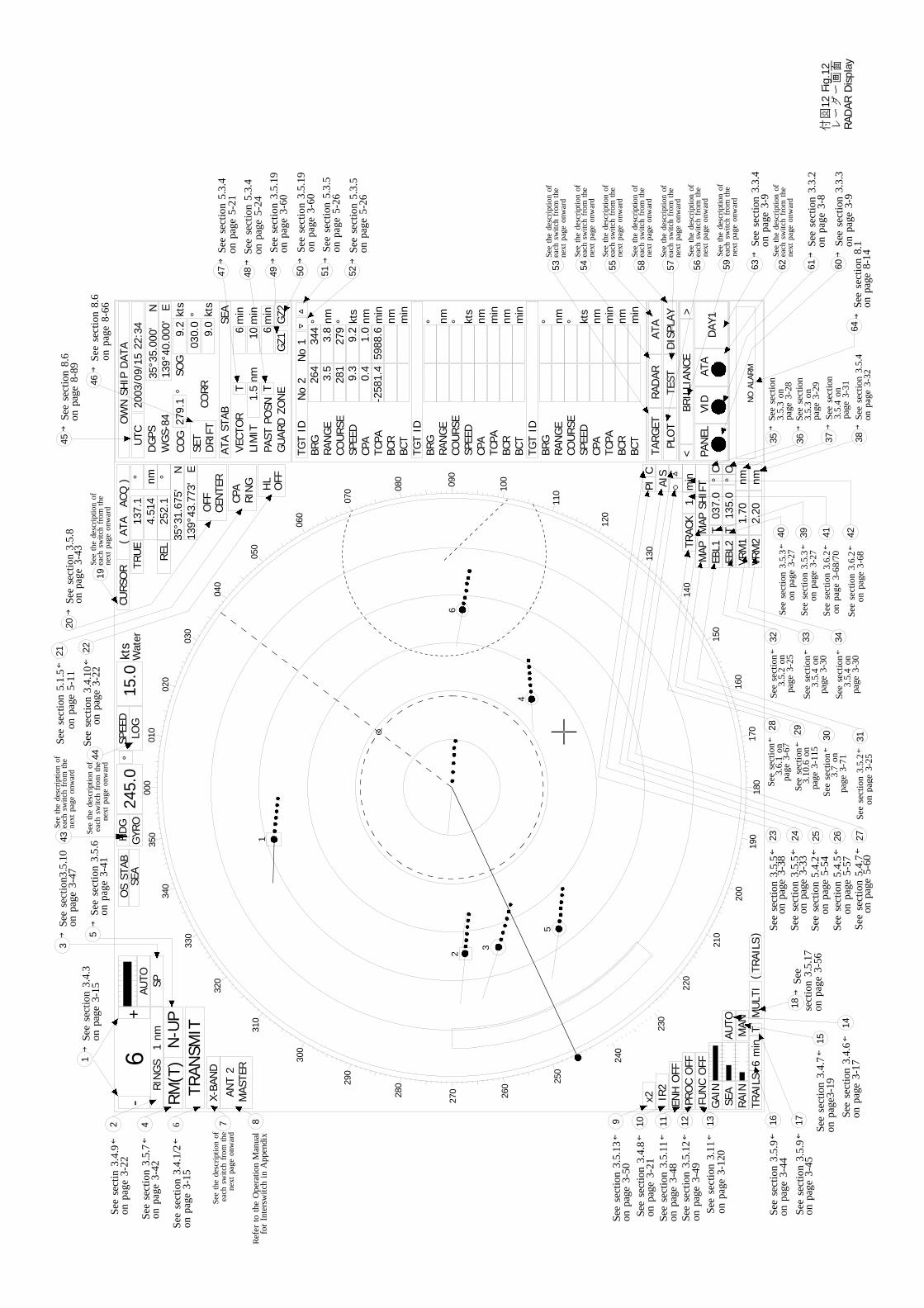
1
2 4 6 87
3
5
9 10 11 12 13
14
15
17
2043
29 30 31
32 33
35
21 22
50 51 52
44
48 49
53 54 57
45
46
47
19
16
4125 26 27
28
39
3736
56 61 605958
RIN
GS
1nm
-+
RM(T
)N
-UP
TRAN
SMIT
X-BA
ND
ANT
2M
ASTE
R6SP
AUTO
000
245.
0H
DG
GYR
OO
SST
ABSE
A°
SPEE
DLO
G15
.0kt
s
010
020
030
040
050
060
070 08
0 090
100
110
120
130
140
150
160
170
180
190
200
210
220
230
240
250
260
27028
0290
300
310
320
330
340
350
TRAI
LS6
min
TRA
INSE
AG
AIN
MAN
AUTO
FUN
CO
FFPR
OC
OFF
ENH
OFF
IR2
x2
nm2.
20VR
M2
nm1.
70VR
M1
EBL2
EBL1
TC
°03
7.0
TO
°13
5.0
MAP
MAP
SHIF
T
△○PI
CURS
OR
(AT
AAC
Q) °
TRU
Enm
137.
14.
514
°RE
L25
2.1
35°3
1.67
5'N
139°
43.7
73'
EO
FFCE
NTE
R
CPA
RIN
G HL
OFF
NO
ALAR
M
PAN
ELVI
DAT
AD
AY1
<>
BRIL
LIAN
CE
TARG
ETPL
OT
RAD
ARTE
STAT
AD
ISPL
AY
TGT
ID▽
△
°BR
Gnm
RAN
GE
°CO
URS
Ekt
sSP
EED
nmCP
Am
inTC
PAnm
BCR
min
BCT
TGT
ID°
BRG
nmRA
NG
E°
COU
RSE
kts
SPEE
Dnm
CPA
min
TCPA
nmBC
Rm
inBC
TTG
TID
°BR
Gnm
RAN
GE
°CO
URS
Ekt
sSP
EED
nmCP
Am
inTC
PAnm
BCR
min
BCT
OW
NSH
IPD
ATA
UTC
2003
/09/
1522
:34
35°3
5.00
0'N
139°
40.0
00'
ED
GPS
WG
S-84
ATA
STAB
SEA
COG
SOG
kts
°27
9.1
9.2
°03
0.0
kts
9.0
SET
DRI
FTCO
RR
min
6m
in10
VECT
OR
TLI
MIT
nm1.
5PA
STPO
SNT
min
GU
ARD
ZON
EG
Z1G
Z26
No
2N
o1
264
3.5
281
9.3
0.4
-258
1.4
344
3.8
279
9.2
1.0
5988
.6
1
2
3
5
4
6
min
1TR
ACK
C
MU
LTI
TRAI
LS(
)
Wat
er
→Se
ese
ctio
n3.
4.3
onpa
ge3-
15
→Se
ese
ctio
n3.5
.10
onpa
ge3-
47
See
sect
in3.
4.9←
onpa
ge3-
22
See
sect
ion
3.5.
7←on
page
3-42
See
sect
ion
3.4.
1/2←
onpa
ge3-
15
See
sect
ion
3.5.
13←
onpa
ge3-
50Se
ese
ctio
n3.
4.8←
onpa
ge3-
21Se
ese
ctio
n3.
5.11
←on
page
3-48
See
sect
ion
3.5.
12←
onpa
ge3-
49Se
ese
ctio
n3.
11←
onpa
ge3-
120
See
sect
ion
3.5.
9←on
page
3-44
See
sect
ion
3.5.
9←on
page
3-45
See
sect
ion
3.4.
6←on
page
3-17
See
sect
ion
3.4.
7←on
page
3-19
→Se
ese
ctio
n3.
5.8
onpa
ge3-
43
See
sect
ion
5.1.
5←on
page
5-11
See
sect
ion
3.4.
10←
onpa
ge3-
22→
See
sect
ion
3.5.
6on
page
3-41
23 24Se
ese
ctio
n3.
5.5←
onpa
ge3-
33
AIS
See
sect
ion
3.5.
5←on
page
3-38
See
sect
ion
5.4.
2←on
page
5-54
See
sect
ion
5.4.
5←on
page
5-57
See
sect
ion
5.4.
7←on
page
5-60
See
sect
ion←
page
3-67
See
sect
ion
3.5.
2←on
page
3-25
40
→Se
ese
ctio
n8.
6on
page
8-89 →
See
sect
ion
8.6
onpa
ge8-
66
→Se
ese
ctio
n5.
3.4
onpa
ge5-
21→
See
sect
ion
5.3.
4on
page
5-24
→Se
ese
ctio
n3.
5.19
onpa
ge3-
60→
See
sect
ion
3.5.
19on
page
3-60
→Se
ese
ctio
n5.
3.5
onpa
ge5-
26→
See
sect
ion
5.3.
5on
page
5-26
55 6263
64→
See
sect
ion
8.1
onpa
ge8-
14
R efe
rto
the
Ope
ratio
nM
anua
lfo
rIn
ters
witc
hin
App
endi
x
See
the
desc
riptio
nof
next
page
onw
ard
each
switc
hfr
omth
e
→Se
ese
ctio
n3.
3.3
onpa
ge3-
9
→Se
ese
ctio
n3.
3.2
onpa
ge3-
8
→Se
ese
ctio
n3.
3.4
onpa
ge3-
9
18→
See
sect
ion
3.5.
17
38→
See
sect
ion
3.5.
4on
page
3-32
4234
See
the
desc
riptio
nof
next
page
onw
ard
each
switc
hfr
omth
eSe
eth
ede
scrip
tion
of
next
page
onw
ard
each
switc
hfr
omth
e
See
the
desc
riptio
nof
next
page
onw
ard
each
switc
hfr
omth
e
See
the
desc
riptio
nof
next
page
onw
ard
each
switc
hfr
omth
e
See
the
desc
riptio
nof
next
page
onw
ard
each
switc
hfr
omth
e
See
the
desc
riptio
nof
next
page
onw
ard
each
switc
hfr
omth
e
See
the
desc
riptio
nof
next
page
onw
ard
each
switc
hfr
omth
e
See
the
desc
riptio
nof
next
page
onw
ard
each
switc
hfr
omth
e
See
the
desc
riptio
nof
next
page
onw
ard
each
switc
hfr
omth
e
See
the
desc
riptio
nof
next
page
onw
ard
each
switc
hfr
omth
e
See
the
desc
riptio
nof
next
page
onw
ard
each
switc
hfr
omth
e
onpa
ge3-
56
3.6.
1on
See
sect
ion←
page
3-11
53.
10.6
on
See
sect
ion←
page
3-71
3.7
on
See
sect
ion←
page
3-25
3.5.
2on
See
sect
ion←
page
3-30
3.5.
4on
See
sect
ion←
page
3-30
3.5.
4on
See
sect
ion
3.5.
3←on
page
3-27
See
sect
ion
3.5.
3←on
page
3-27
See
sect
ion
3.6.
2←on
page
3-68
/70
See
sect
ion
3.6.
2←on
page
3-68
→Se
ese
ctio
n
page
3-28
3.5.
3on
→Se
ese
ctio
n
page
3-29
3.5.
3on
→Se
ese
ctio
n
page
3-31
3.5.
4on
付図
12Fi
g.12
レー
ダー
画面
RAD
ARD
ispl
ay
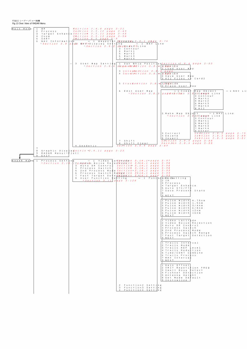
Main Menu - 1 IR →2 Process →3 Target Enhance →4 Zoom →5 SART →6 NAV Information - 1 Waypoint Display →
→Section 3.8 page 3-74 2 NAV Display Setting - 1 NAV Line→Section 3.8.2 page 3-75 2 Coast Line
3 Contour4 Mark15 Mark26 Mark37 Mark4
- 3 User Map Setting - 1 Own Ship Position →→Section 3.8.4 page 3-82 2 Load →Section 3.8.4 page 3- - 1 Device
2 Load User Map3 Unload →Section 3.8.4 page4 Save →Section 3.8.4 page 3- - 1 Device
2 Save User Map3 All Files to Card2
5 Erase →Section 3.8.4 page 3- - 1 Device2 Erase User Map
6 Edit User Map - 1 Clear Map Object - 1 NAV Line→Section 3.8.3 page 3-76 →Section 3.8.3 page 2 Coast Line
3 Contour4 Mark15 Mark26 Mark37 Mark48 All
2 Make Map Object - 1 NAV Line→Section 3.8.3 page 2 Coast Line
3 Contour4 Mark15 Mark26 Mark37 Mark48 Enter
3 Correct →4 Delete →5 Insert →
7 Shift →8 Shift Clear →
4 Geodetic →78 Graphic Display →9 RADAR Menu(→Plot)0 EXIT
RADAR Menu - 1 Process Setting - 1 Video Latitude →→Section 3.10.1 page 3- 2 Video Noise Rejection →
3 Auto DR Control →4 Process Switch →5 2nd Process Mode →6 Process Switch Range →7 Fast Target Detection →8 User Function Setting - 1 Function1 Setting - 1 Mode
→Section 3.11 page 3-120 2 IR3 Process 4 Target Enhance5 Auto STC/FTC7 Save Present State89 NEXT↓1 Pulse Width 0.75nm2 Pulse Width 1.5nm3 Pulse Width 3/4nm4 Pulse Width 6/8nm5 Pulse Width 12nm6 Pulse Width 16nm9 NEXT↓1 Video Latitude2 Video Noise Rejection3 Auto DR Control4 Process Switch5 2nd Process Mode6 Process Switch Range7 Fast Target Detection9 NEXT↓1 Trails Interval2 Trails Mode3 Trails REF Level4 Trails Reduction5 Time/CONT Combine6 Trails Process7 MAX Interval9 NEXT↓1 Gain Offset2 XMIT Repetition FREQ3 Small Bouy Detect4 Fishnet Detection5 Antenna Height8 Set Mode Default9 Initialize
2 Function2 Setting3 Function3 Setting4 Function4 Setting
Section 3.8.4 page 3-83
Section 3.8.4 page 3-88Section 3.8.4 page 3-88
Section 3.8.5 page 3-89
Section 3.10.1 page 3-97Section 3.10.1 page 3-98Section 3.10.1 page 3-98Section 3.10.1 page 3-98Section 3.10.1 page 3-99Section 3.10.1 page 3-99Section 3.10.1 page 3-99
Section 3.4.8 page 3-21Section 3.5.12 page 3-49Section 3.5.11 page 3-48
Section 6.5 page 6-9Section 3.8.1 page 3-74
Section 3.5.13 page 3-50
Sectin 3.4.11 page 3-23
Section 3.8.3 page 3-79Section 3.8.3 page 3-80Section 3.8.3 page 3-81
付図13 レーダーメニュー階層Fig.13 Over View of RADAR Menu
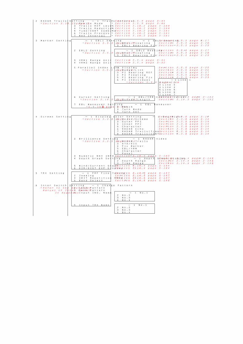
2 RADAR Trails Setting - 1 Trails Interval →→Section 3.10.2 page 3- 2 Trails Mode →
3 Trails REF Level →4 Trails Reduction →5 Time/CONT Combine →6 Trails Process →7 MAX Interval →
3 Marker Setting - 1 EBL1 Setting - 1 EBL1 Bearing →→Section 3.5.3 page 3-27 2 EBL1 Floating →
3 EBL1 Bearing Fix →
2 EBL2 Setting - 1 EBL2 Bearing →→Section 3.5.3 page 3-27 2 EBL2 Floating →
3 EBL2 Bearing Fix →
3 VRM1 Range Unit →4 VRM2 Range Unit →
5 Parallel Index Line - 1 Display →→Section 3.5.5 page 3-33 2 Range Link →
3 PI Bearing REF →4 PI Floating →5 PI Bearing Fix →6 PI Individual - 1 Line 1
→Section 3.5.5 page 3-40 2 Line 23 Line 34 Line 45 Line 56 Line 67 Line 7
6 Cursor Setting - 1 EBL/VRM Control Cursor →→Section 3.10.3 page 3-102 2 Cursor Length →
7 EBL Maneuver Setting - 1 EBL Maneuver→3.5.16章 page 3-55P 2 Reach
3 Turn Mode4 Turn Set
4 Screen Setting - 1 Display Color Setting - 1 Day/Night →→Section 3.3.8 page 3-12 2 Color Scheme →
3 Outer PPI →4 Inner PPI →5 Character →6 RADAR Echo →7 RADAR Trails(Time) →8 RADAR Trails(CONT) →
2 Brilliance Setting - 1 RADAR Video→Section 3.3.5 page 3-10 2 RADAR Trails
3 ATA/AIS4 Fix Marker5 EBL/VRM6 Character7 Panel
3 Numeric NAV INFO →4 Depth Graph Setting - 1 Depth Graph Display →
2 Depth Range →3 Time Range →
5 Wind/Current Graph →6 DIR/DIST EXP Display →
5 TRX Setting - 1 PRF Fine Tuning →2 Jamming →4 XMIT Repetition FREQ →6 Band Select →
6 Inter Switch Setting - 1 Change Pattern→Refer to the Operation 2 Load Pattern
Manual of Inter Switch 3 Save PatternIn Appendix 4 Input IND. Name - 1 No.1
2 No.23 No.34 No.4
5 Input TRX Name - 1 No.12 No.23 No.34 No.4
Section 3.10.5 page 3-107
Section 3.10.4 page 3-104
Section 3.10.5 page 3-107
Section 3.3.8 page 3-14
Section 3.10.5 page 3-107Section 3.10.5 page 3-108
Section 3.5.3 page 3-28
Section 3.5.3 page 3-29
Section 3.5.3 page 3-29
Section 3.5.4 page 3-31
Section 3.5.3 page 3-27Section 3.5.3 page 3-28
Section 3.5.3 page 3-27
Section 3.10.2 page 3-101Section 3.10.2 page 3-101Section 3.10.2 page 3-101
Section 3.10.2 page 3-100
Section 3.10.4 page 3-104
Section 3.5.9 page 3-44
Section 3.10.2 page 3-100Section 3.5.9 page 3-46
Section 3.5.4 page 3-32
Section 3.10.4 page 3-103
Section 3.3.8 page 3-12Section 3.3.8 page 3-13Section 3.3.8 page 3-14
Section 3.10.3 page 3-102Section 3.10.3 page 3-102
Section 3.10.4 page 3-105
Section 3.5.5 page 3-35Section 3.5.5 page 3-36Section 3.5.5 page 3-37Section 3.5.5 page 3-38Section 3.5.5 page 3-39
Section 3.10.4 page 3-106Section 3.10.4 page 3-106
Section 3.3.8 page 3-14Section 3.3.8 page 3-14Section 3.3.8 page 3-14Section 3.3.8 page 3-14
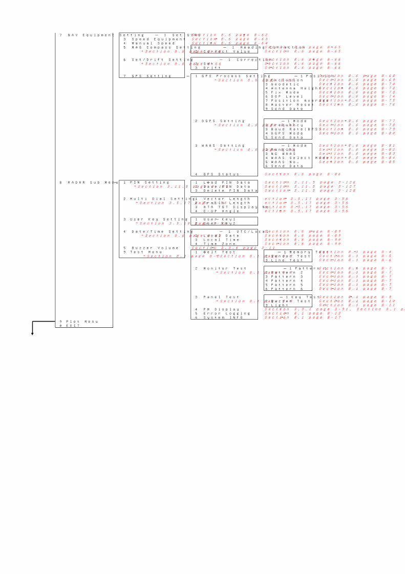
7 NAV Equipment Setting - 1 Set GYRO →3 Speed Equipment →4 Manual Speed →5 MAG Compass Setting - 1 Heading Correction →
→Section 8.6 page 8-65 2 Correct Value →
6 Set/Drift Setting - 1 Correction →→Section 8.6 page 8-66 2 Set →
3 Drift →
7 GPS Setting - 1 GPS Process Setting - 1 Position →→Section 8.6 page 8-68 2 Exclusion →
3 Geodetic →4 Antenna Height →5 Fix Mode →6 DOP Level →7 Position Average →8 Master Reset →9 Send Date
2 DGPS Setting - 1 Mode →→Section 8.6 page 8-77 2 Frequency →
3 Baud Rate(BPS) →4 DGPS Mode →5 Send Data
3 WAAS Setting - 1 Mode →→Section 8.6 page 8-81 2 Ranging →
3 NG WAAS →4 WAAS Select Mode →5 WAAS No. →6 Send Data
4 GPS Status →
8 RADAR Sub Menu - 1 PIN Setting - 1 Load PIN Data →→Section 3.11.5 page 3-126 2 Save PIN Data →
3 Delete PIN Data →
2 Multi Dial Setting 1 Vector Length →→Section 3.5.17 page 3-56 2 Trails Length →
3 ATA TGT Display No. →4 C-UP Angle →
3 User Key Setting - 1 User Key1→Section 3.5.18 page 3-58 2 User Key2
4 Date/Time Setting - 1 UTC/Local →→Section 8.6 page 8-89 2 Local Date →
3 Local Time →4 Time Zone →
5 Buzzer Volume →9 Test Menu - 1 Self Test - 1 Memory Test →
→Section 8.1 page 8-2 →Section 8.1 page 8-3 2 Sensor Test →3 Line Test →
2 Monitor Test - 1 Pattern 1 →→Section 8.1 page 8-7 2 Pattern 2 →
3 Pattern 3 →4 Pattern 4 →5 Pattern 5 →6 Pattern 6 →
3 Panel Test - 1 Key Test →→Section 8.1 page 8-8 2 Buzzer Test →
3 Light →4 PM Display →5 Error Logging →6 System INFO →
9 Plot Menu0 EXIT
Section 8.1 page 8-10Section 8.1 page 8-11
Section 8.1 page 8-13
Section 8.1 page 8-9
Section 8.1 page 8-7Section 8.1 page 8-7Section 8.1 page 8-7Section 8.1 page 8-7Section 8.1 page 8-7
Section 8.6 page 8-62Section 8.6 page 8-63Section 8.6 page 8-64
Section 3.3.6 page 3-11
Section 8.6 page 8-89
Section 8.6 page 8-90Section 8.6 page 8-90
Section 8.1 page 8-17
Section 8.6 page 8-65
Section 8.6 page 8-66
Section 8.6 page 8-65
Section 8.6 page 8-66
Section 8.6 page 8-66
Section 8.6 page 8-68Section 8.6 page 8-69Section 8.6 page 8-70Section 8.6 page 8-72Section 8.6 page 8-73Section 8.6 page 8-74Section 8.6 page 8-75Section 8.6 page 8-76
Section 8.6 page 8-77Section 8.6 page 8-78Section 8.6 page 8-79Section 8.6 page 8-80
Section 8.6 page 8-81Section 8.6 page 8-82Section 8.6 page 8-83Section 8.6 page 8-84Section 8.6 page 8-85
Section 8.6 page 8-86
Section 3.11.5 page 3-126Section 3.11.5 page 3-127Section 3.11.5 page 3-128
ection 3.5.17 page 3-56ection 3.5.17 page 3-56ection 3.5.17 page 3-56ection 3.5.17 page 3-56
Section 8.1 page 8-7
Section 8.6 page 8-89
Section 8.1 page 8-4Section 8.1 page 8-5Section 8.1 page 8-6
Section 3.9.1 page 3-91, Section 8.1 page 8-12
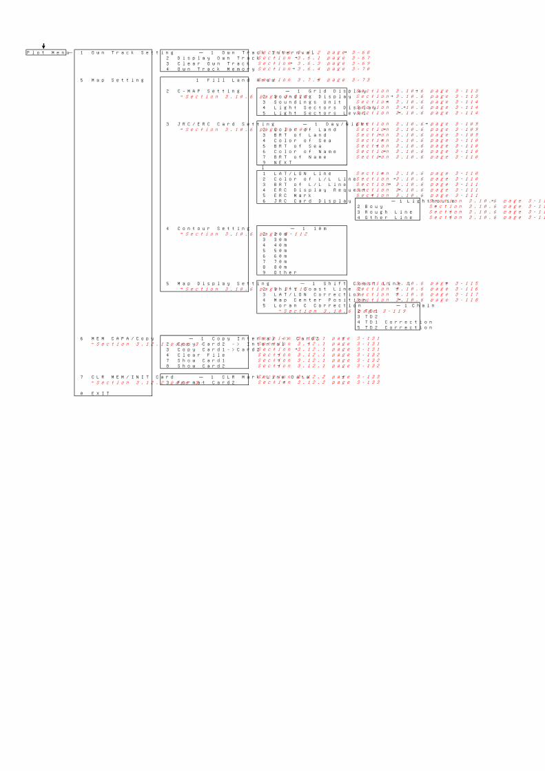
Plot Menu - 1 Own Track Setting - 1 Own Track Internval →2 Display Own Track →3 Clear Own Track →4 Own Track Memory →
5 Map Setting 1 Fill Land Area →
2 C-MAP Setting - 1 Grid Display →→Section 3.10.6 page 3-113 2 Sounding Display →
3 Soundings Unit →4 Light Sectors Display →5 Light Sectors Level →
3 JRC/ERC Card Setting - 1 Day/Night →→Section 3.10.6 page 3-109 2 Color of Land →
3 BRT of Land →4 Color of Sea →5 BRT of Sea →6 Color of Name →7 BRT of Name →9 NEXT↓1 LAT/LON Line →2 Color of L/L Line →3 BRT of L/L Line →4 ERC Display Request →5 ERC Mark →6 JRC Card Display - 1 Lighthouse →
2 Bouy →3 Rough Line →4 Other Line →
4 Contour Setting - 1 10m→Section 3.10.6 page 3-112 2 20m
3 30m4 40m5 50m6 60m7 70m8 80m9 Other
5 Map Display Setting - 1 Shift Coast Line 1 →→Section 3.10.6 page 3-115 2 Shift Coast Line 2 →
3 LAT/LON Correction →4 Map Center Position →5 Loran C Correction - 1 Chain
→Section 3.10.6 page 3-119 2 TD13 TD24 TD1 Correction5 TD2 Correction
6 MEM CAPA/Copy - 1 Copy Internal -> Card2 →→Section 3.12.1 page 3- 2 Copy Card2 -> Internal →
3 Copy Card1->Card2 →4 Clear File →7 Show Card1 →8 Show Card2 →
7 CLR MEM/INIT Card - 1 CLR Mark/Line Data →→Section 3.12.2 page 3- 3 Format Card2 →
0 EXIT
Section 3.10.6 page 3-111Section 3.10.6 page 3-111
Section 3.10.6 page 3-115Section 3.10.6 page 3-116Section 3.10.6 page 3-117Section 3.10.6 page 3-118
Section 3.12.1 page 3-132Section 3.12.1 page 3-132
Section 3.7.3 page 3-73
Section 3.10.6 page 3-111
Section 3.10.6 page 3-110Section 3.10.6 page 3-110Section 3.10.6 page 3-111Section 3.10.6 page 3-111Section 3.10.6 page 3-111
Section 3.10.6 page 3-111
Section 3.6.3 page 3-69Section 3.6.4 page 3-70
Section 3.6.1 page 3-67Section 3.6.2 page 3-68
Section 3.10.6 page 3-109
Section 3.10.6 page 3-110
Section 3.10.6 page 3-113Section 3.10.6 page 3-113Section 3.10.6 page 3-114Section 3.10.6 page 3-114Section 3.10.6 page 3-114
Section 3.12.1 page 3-131Section 3.12.1 page 3-131Section 3.12.1 page 3-131
Section 3.10.6 page 3-110
Section 3.10.6 page 3-110Section 3.10.6 page 3-110
Section 3.10.6 page 3-109Section 3.10.6 page 3-109
Section 3.12.1 page 3-132
Section 3.12.2 page 3-133Section 3.12.2 page 3-133
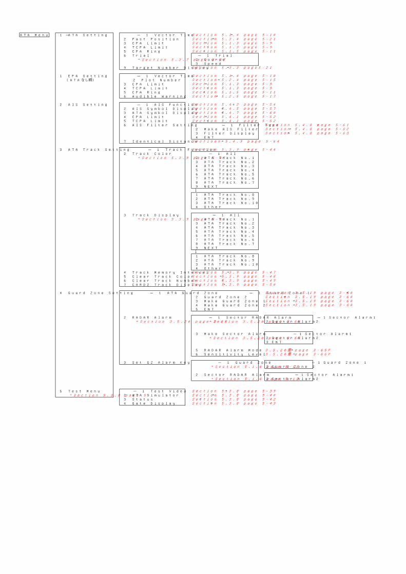
ATA Menu - 1 ATA Setting - 1 Vector Time →2 Past Position →3 CPA Limit →4 TCPA Limit →5 CPA Ring →6 Trial - 1 Trial
→Section 5.3.7 page 5-37 2 Course3 Speed
9 Target Number Display →
1 EPA Setting - 1 Vector Time →(ATAなし時) 2 Plot Number →
3 CPA Limit →4 TCPA Limit →5 CPA Ring →6 Audible Warning →
2 AIS Setting - 1 AIS Function →2 AIS Symbol Display →3 ATA Symbol Display →4 CPA Limit →5 TCPA Limit →6 AIS Filter Setting - 1 Filter Type →
2 Make AIS Filter →3 Filter Display →4 ENT
7 Identical Distance →
3 ATA Track Setting - 1 Track Function →2 Track Color - 1 All
→Section 5.3.9 page 5-45 2 ATA Track No.13 ATA Track No.24 ATA Track No.35 ATA Track No.46 ATA Track No.57 ATA Track No.68 ATA Track No.79 NEXT↓1 ATA Track No.82 ATA Track No.93 ATA Track No.104 Other
3 Track Display - 1 All→Section 5.3.9 page 5-46 2 ATA Track No.1
3 ATA Track No.24 ATA Track No.35 ATA Track No.46 ATA Track No.57 ATA Track No.68 ATA Track No.79 NEXT↓1 ATA Track No.82 ATA Track No.93 ATA Track No.104 Other
4 Track Memory Interval →5 Clear Track Color →6 Clear Track Number →7 CARD2 Track Display →
4 Guard Zone Setting - 1 ATA Guard Zone - 1 Guard Zone 1 →2 Guard Zone 2 →3 Make Guard Zone 1 →4 Make Guard Zone 2 →5 ENT
2 RADAR Alarm - 1 Sector RADAR Alarm - 1 Sector Alarm1→Section 3.5.20 page 3-63 →Section 3.5.20 page 3-66 2 Sector Alarm2
3 Make Sector Alarm - 1 Sector Alarm1→Section 3.5.20 page 3-65 2 Sector Alarm2
3 ENT
5 RADAR Alarm Mode →6 Sensitivity Level →
3 Set GZ Alarm Key - 1 Guard Zone - 1 Guard Zone 1→Section 5.1.6 page 5-12 2 Guard Zone 2
2 Sector RADAR Alarm - 1 Sector Alarm1→Section 5.1.6 page 5-12 2 Sector Alarm2
5 Test Menu - 1 Test Video →→Section 5.3.8 page 5- 2 ATA Simulator →
3 Status →4 Gate Display → Section 5.3.8 page 5-43
Section 5.3.8 page 5-42
Section 5.4.8 page 5-61Section 5.4.8 page 5-62Section 5.4.8 page 5-63
Sectioon 5.4.9 page 5-64
Section 5.2.5 page 5-17
Section 5.3.8 page 5-40
Section 5.3.9 page 5-44
Section 5.1.3 page 5-9Section 5.1.3 page 5-9
Section 5.1.4 page 5-10Section 5.2.4 page 5-15
Section 5.4.2 page 5-54Section 5.4.5 page 5-57
Section 5.4.1 page 5-52Section 5.4.1 page 5-52
Section 5.1.4 page 5-10
Section 5.1.3 page 5-9Section 5.1.3 page 5-9
Section 3.5.19 page 3-60
Section 5.3.9 page 5-50
Section 5.3.9 page 5-47Section 5.3.9 page 5-48Section 5.3.9 page 5-49
Section 3.5.19 page 3-60Section 3.5.19 page 3-60Section 3.5.19 page 3-60
3.5.20章 page 3-65P3.5.20章 page 3-66P
Section 5.4.7 page 5-60
Section 5.1.5 page 5-11
Section 5.1.5 page 5-11
Section 5.3.3 page5-21
Section 5.3.4 page 5-21
Section 5.3.8 page 5-39
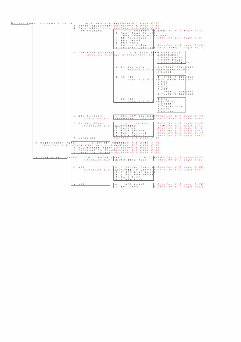
Adjust Menu - 1 Equipment Setup - 1 Bearing Adjustment →2 Range Adjustment →3 Tune Adjustment →4 TRX Setting - 1 Antenna Height →
2 Tune Peak Adjust3 Tune Indicator Adjust4 PM Adjustment →5 MBS Level6 MBS Area7 Output Pulse →8 Antenna Location →
5 COM Port Setting - 1 Baud Rate - 1 COM1(GPS)→Section 8.5 pge 8-39 →Section 8.5 pge 8-39 2 COM2(PC)
3 COM3(NAV1)4 COM4(NAV2)5 COM5(COMPASS)
2 RX Sentence - 1 GPS(LL/COG/SOG)→Section 8.5 page 8-40 2 GPS(WPT/Time)
3 Depth
3 TX Port - 1 TTM(ATA Target)→Section 8.5 page 8-41 2 TLL(ATA Target)
3 OSD4 RSD5 ALR6 AIS7 TTM(AIS Target)8 TLL(AIS Target)
4 RX Port - 1 GPS→Section 8.5 page 8-42 2 DLOG
3 Depth4 Temperture5 Wind6 Current
6 NAV Setting - 1 SEL NAV Equipment →→Section 8.5 page 8-43 2 GPS ANT Location →
7 Sector Blank - 1 Sector1 →→Section 8.5 page 8-46 2 Sector2 →
3 Sector3 →4 Make Sector1 →5 Make Sector2 →6 Make Sector3 →
9 Language →
2 Maintenance Menu 1 Safety Switch →→Section 8.5 page 8-49 2 Partial Master Reset →
3 ALL Master Reset →4 Internal To Card2 →5 Card2 To Internal →
9 SP/ATA INIT Setup - 1 Noise Level - 1 Main →→Section 8.5 page 8-54 3 Setting Mode →
2 ATA - 1 Vector Constant →→Section 8.5 page 8-56 2 Video TD Level →
3 Video High Level4 Video Low Level5 Gate Size6 Limit Ring
3 MBS - 1 MBS Level →2 MBS Area →
Section 8.5 page 8-56Section 8.5 page 8-57
Section 8.6 page 8-91
Section 8.5 page 8-32
Section 8.5 page 8-33Section 8.5 page 8-34
Section 8.5 page 8-35
Section 8.5 page 8-47Section 8.5 page 8-47
Section 8.5 page 8-48
Section 8.5 page 8-46Section 8.5 page 8-46Section 8.5 page 8-46Section 8.5 page 8-47
Section 8.5 page 8-43Section 8.5 page 8-44
Section 8.5 page 8-37Section 8.5 page 8-36
Section 8.5 page 8-52
Section 8.5 page 8-58Section 8.5 page 8-59
Section 8.5 page 8-53
Section 8.5 page 8-54Section 8.5 page 8-55
Section 8.5 page 8-49Section 8.5 page 8-50Section 8.5 page 8-51