JIMEC Thermal modeling and Simulation of HX Conference Paper
19
The 8 th Jordanian International Mechanical Engineering Conference (JIMEC’8) Amman – Jordan THERMAL MODELING AND SIMULATION OF AN INDUSTRAIL SHELL AND TUBE HEAT EXCHANGER Fadi A. Ghaith, [email protected] School of Engineering and Physical Sciences, Heriot Watt University, Dubai Campus, UAE. Ahmed S. Izhar, [email protected] School of Engineering and Physical Sciences, Heriot Watt University, Dubai Campus, UAE. ABSTRACT In this paper, an industrial shell-and-tube heat exchanger utilized for the purpose of cooling raw natural gas by means of mixture of sale gases is considered. The main objective of this work is to provide an optimum and reliable thermal design of a single-shelled finned tubes heat exchanger to replace the existing two- shell and tube heat exchanger due to the space limitations in the plant. A comprehensive thermal model was developed using the effectiveness-NTU method. The shell-side and tube-side overall heat transfer coefficient were determined using Bell-Delaware method and Dittus-Boelter correlation, respectively. The obtained results showed that the required area to provide a thermal duty of 1.4 MW is about 1132 m 2 with tube-side and shell-side heat transfer coefficients of 950 W/m 2 K and 495 W/m 2 K, respectively. In order to verify the obtained results generated from the mathematical model, a numerical study was carried out using HTRI software which showed a good match in terms of the heat transfer area and the tube-side heat transfer coefficient. Keywords: shell-and-tube heat exchanger, heat transfer coefficient, HTRI. 1. INTRODUCTION Shell and tube heat exchangers are widely used in petrochemical and energy industries because of their ability to adapt different process operating conditions. Their robustness and geometry make them very suitable for high temperature and pressure applications. A compact formulation was developed by Serna and Jiminez [1,2] based on Bell-Delaware method that integrates the pressure drop, the heat transfer area, and the film heat transfer coefficient. Other widely accepted met hods like Kern’s method [3,4] and Donohue’s correlation may also be used but they are old and out-dated and lacking accuracy. On the other hand, LMTD method and the ε-NTU approaches are considered powerful in determining the heat transfer
-
Upload
ahmed-sohail-izhar -
Category
Documents
-
view
230 -
download
0
Transcript of JIMEC Thermal modeling and Simulation of HX Conference Paper

The 8th Jordanian International Mechanical Engineering Conference (JIMEC’8) Amman – Jordan
THERMAL MODELING AND SIMULATION OF AN INDUSTRAIL SHELL AND
TUBE HEAT EXCHANGER
Fadi A. Ghaith, [email protected] School of Engineering and Physical Sciences, Heriot Watt
University, Dubai Campus, UAE.
Ahmed S. Izhar, [email protected] School of Engineering and Physical Sciences, Heriot Watt
University, Dubai Campus, UAE.
ABSTRACT
In this paper, an industrial shell-and-tube heat exchanger utilized for the purpose of cooling raw natural
gas by means of mixture of sale gases is considered. The main objective of this work is to provide an
optimum and reliable thermal design of a single-shelled finned tubes heat exchanger to replace the
existing two- shell and tube heat exchanger due to the space limitations in the plant. A comprehensive
thermal model was developed using the effectiveness-NTU method. The shell-side and tube-side overall
heat transfer coefficient were determined using Bell-Delaware method and Dittus-Boelter correlation,
respectively. The obtained results showed that the required area to provide a thermal duty of 1.4 MW is
about 1132 m2 with tube-side and shell-side heat transfer coefficients of 950 W/m2K and 495 W/m2K,
respectively. In order to verify the obtained results generated from the mathematical model, a numerical
study was carried out using HTRI software which showed a good match in terms of the heat transfer area
and the tube-side heat transfer coefficient.
Keywords: shell-and-tube heat exchanger, heat transfer coefficient, HTRI.
1. INTRODUCTION
Shell and tube heat exchangers are widely used in petrochemical and energy industries because of their
ability to adapt different process operating conditions. Their robustness and geometry make them very
suitable for high temperature and pressure applications. A compact formulation was developed by Serna
and Jiminez [1,2] based on Bell-Delaware method that integrates the pressure drop, the heat transfer area,
and the film heat transfer coefficient. Other widely accepted methods like Kern’s method [3,4] and
Donohue’s correlation may also be used but they are old and out-dated and lacking accuracy. On the other
hand, LMTD method and the ε-NTU approaches are considered powerful in determining the heat transfer

The 8th Jordanian International Mechanical Engineering Conference (JIMEC’8) Amman – Jordan
rate and the heat transfer area [5]. Shell and tube heat exchangers have many design considerations that
need to be taken into account while modeling and designing the heat exchanger to achieve better
performance. Hosseini et al. [6] performed an experiment comparing the heat transfer coefficient and
pressure drop for three different types of copper tubes (smooth, corrugated and micro-fins) and came out
with the result that at higher Reynolds number the performance of the heat exchanger with micro-finned
tubes greatly improved, if the geometry and all other configurations kept constant. Fabbri [7] goes as far
as comparing the heat transfer performance of a smooth wall channel with a corrugated one under laminar
flow conditions, with the aid of a finite element model. He found out that treated surfaces and rough
surfaces showed enhancement of up to 30% in heat transfer rate with respect to the heat dissipated by the
usual flat wall of same volume. This paper aims to develop a comprehensive thermal model which can
describe the thermal performance of shell-and-tube heat exchanger. The obtained model is implemented
to design a large-scale industrial shell and tube heat exchanger by determining the geometry and
estimating the heat transfer coefficients. Also a numerical study was established to validate the results
extracted from theory.
2. GENERAL DESCRIPTION
In this section, the system description and the associated industrial applications are discussed briefly.
2.1 Scope of Application
Raw natural gas (NG) from the gas wells consists of mainly methane along with other impurities like
heavier hydrocarbons, condensates, water content, traces of mercury, and other gaseous components like
CO2, N2, He, H2S and SO2 [8]. Methane (and ethane, in some cases) needs to be separated from the
impurities before it can be collected. The shell-and-tube heat exchanger modeled in this paper is basically
used to cool the raw natural gas to reduce the work input in processing of sales gases. The whole process
is shown schematically by Fig.1. During operation, hot raw NG is fed into the heat exchanger to be
cooled, which is then passes through a control valve to reduce pressure. Further reduction in pressure
reduces the temperature. At this stage, the raw NG is split into vapors (methane and ethane), condensate
(other impurities) and water. Finally, the vapors (sales gas) is fed back into the heat exchanger (from the
other side) to cool the incoming raw NG and bring the sales gas to an optimum temperature, ready for
transportation.

The 8th Jordanian International Mechanical Engineering Conference (JIMEC’8) Amman – Jordan
Fig. 1: Schematic of the heat exchanger unit.
2.2 Problem Statement
This work involves thermal design of a single shell-and-tube heat exchanger such to fulfill the operating
conditions and the space criteria of the plant. Table1 summarize the basic process conditions as well as
the main geometry requirements.
3. MODEL FORMULATION
In this section, the thermal model was formulated to predict the heat transfer coefficients and hence the
heat transfer surface area. The shell-side and tube-side overall heat transfer coefficient were determined
using Bell-Delaware method and Dittus-Boelter correlation, respectively. On the other hand, the
effectiveness-NTU method was used to calculate the heat transfer surface area. The main assumptions
underlay this formulation are [5]:
i. No external heat interaction takes place.
ii. Axial conduction is negligible.
iii. Kinetic and potential changes are assumed negligible.
iv. The overall heat transfer coefficient, U, remains constant throughout the heat exchanger.
v. The specific heat capacity, Cp, remains constant throughout the heat exchanger.
vi. The temperature of each fluid is constant over any cross-section of its path through the heat
exchanger.
The 8th Jordanian International Mechanical Engineering Conference (JIMEC’8) Amman – Jordan
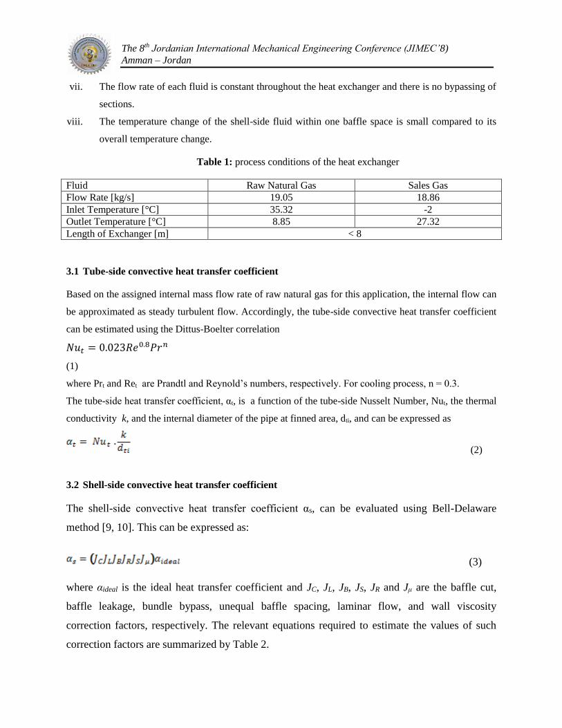
vii. The flow rate of each fluid is constant throughout the heat exchanger and there is no bypassing of
sections.
viii. The temperature change of the shell-side fluid within one baffle space is small compared to its
overall temperature change.
Table 1: process conditions of the heat exchanger
Fluid Raw Natural Gas Sales Gas Flow Rate [kg/s] 19.05 18.86 Inlet Temperature [°C] 35.32 -2 Outlet Temperature [°C] 8.85 27.32 Length of Exchanger [m] < 8
3.1 Tube-side convective heat transfer coefficient
Based on the assigned internal mass flow rate of raw natural gas for this application, the internal flow can
be approximated as steady turbulent flow. Accordingly, the tube-side convective heat transfer coefficient
can be estimated using the Dittus-Boelter correlation
𝑁𝑢𝑡 = 0.023𝑅𝑒0.8𝑃𝑟𝑛
(1)
where Prt and Ret are Prandtl and Reynold’s numbers, respectively. For cooling process, n = 0.3.
The tube-side heat transfer coefficient, αt, is a function of the tube-side Nusselt Number, Nut, the thermal
conductivity k, and the internal diameter of the pipe at finned area, dti, and can be expressed as
(2)
3.2 Shell-side convective heat transfer coefficient
The shell-side convective heat transfer coefficient αs, can be evaluated using Bell-Delaware
method [9, 10]. This can be expressed as:
(3)
where αideal is the ideal heat transfer coefficient and JC, JL, JB, JS, JR and Jμ are the baffle cut,
baffle leakage, bundle bypass, unequal baffle spacing, laminar flow, and wall viscosity
correction factors, respectively. The relevant equations required to estimate the values of such
correction factors are summarized by Table 2.
The 8th Jordanian International Mechanical Engineering Conference (JIMEC’8) Amman – Jordan
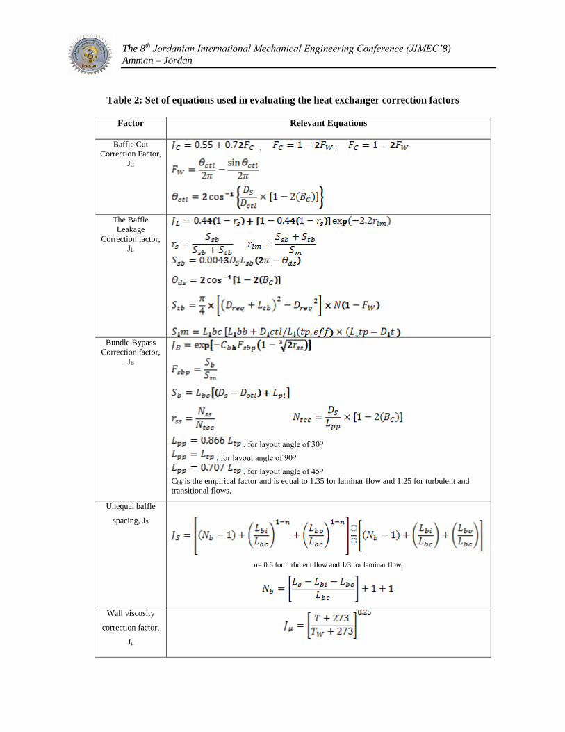
Table 2: Set of equations used in evaluating the heat exchanger correction factors
Factor Relevant Equations
Baffle Cut
Correction Factor,
JC
, ,
The Baffle
Leakage
Correction factor,
JL
Bundle Bypass
Correction factor,
JB
, for layout angle of 30ᴼ
, for layout angle of 90ᴼ
, for layout angle of 45ᴼ
Cbh is the empirical factor and is equal to 1.35 for laminar flow and 1.25 for turbulent and
transitional flows.
Unequal baffle
spacing, JS
n= 0.6 for turbulent flow and 1/3 for laminar flow;
Wall viscosity
correction factor,
Jμ

The 8th Jordanian International Mechanical Engineering Conference (JIMEC’8) Amman – Jordan
The ideal tube bank convective heat transfer coefficient is calculated by
(4)
where Ji is the heat transfer factor and is evaluated using the equations (9a), (9b) and (9c):
where a1, a2, a3 and a4 are constants which depend on the Reynolds number and the tube layout
angle as listed in Table 2. Dreq is the equivalent projected diameter and is influenced by the fin
root diameter, Dfr, the fin height, Lfh, the fin density, Nf, and the fin thickness as expressed
below:
3.3 ε-NTU Method
The effectiveness, ε of the heat exchanger is defined as
Also it should be noted that the effectiveness for the counter flow configuration can be written
as:
where CR is the ratio between the highest and lowest thermal capacitances ratio and NTU is the
no. of transfer units which is defined as:
CRNTUCR
CRNTU
1exp1
1exp1

The 8th Jordanian International Mechanical Engineering Conference (JIMEC’8) Amman – Jordan
where Cmin is the minimum thermal capacitance of the fluids and U is the overall heat transfer
coefficient which can takes into account the effect of fouling and the influence of fins and may
be expressed mathematically as follow:
The effectiveness-NTU method is used to determine the required heat transfer area of the subject
heat exchanger.
Table 3: Empirical coefficients required to determine the heat transfer factor Ji
Layout Re a1 a2 a3 a4
30ᴼ
105-104 0.321 -0.388
1.450 0.519
104-103 0.321 -0.388
103-102 0.593 -0.477
102-10 1.360 -0.657
<10 1.400 -0.667
45ᴼ
105-104 0.370 -0.396
1.930 0.500
104-103 0.370 -0.396
103-102 0.730 -0.500
102-10 0.498 -0.656
<10 1.550 -0.667
90ᴼ
105-104 0.370 -0.395
1.187 0.370
104-103 0.107 -0.266
103-102 0.408 -0.460
102-10 0.900 -0.631
<10 0.970 -0.667
4. RESULTS AND DISCUSSION
This section describes the main findings obtained by solving the mathematical model provided in section
3 and the main results obtained form the HTRI numerical study.
4.1 HTRI Numerical Simulation
Heat Transfer Research Inc. (HTRI) is the most widely used tool for designing, rating and
simulating heat exchangers. The program Xist is a program that follows the industry standard to
design, rate and simulate a shell-and-tube type heat exchanger. Another program named Xvib
was used to perform the associated flow-induced vibration analysis including determination of
minC
UANTU

The 8th Jordanian International Mechanical Engineering Conference (JIMEC’8) Amman – Jordan
natural frequencies and amplitudes of vibration of individual tubes in a bundle. All the
simulations and ratings were performed using HTRI Xchanger Suite 5. Multiple iteration were
carried out before achieving the desired rating of the exchanger. The set of geometrical input
parameters are shown in Table 4. Also the material and process properties are listed in Table 5
and 6, respectively.
Table 4: Heat exchanger input geometry parameters
Type of Heat Exchanger NEN
Shell internal diameter 1000 mm
Shell orientation Horizontal
Hot fluid Tube-side
Tube diameter 15.875 mm
Tube thickness 1.753 mm
Tube pitch 23.812 mm
Pitch ratio 1.5
Tube layout angle 30o
Tubepasses 1
Length 6 m
Tube Material Carbon Steel
Fin type Low fin
Fins/unit length 1023.6 fin/m
Fin root diameter 12.7 mm
Fin height 1.448 mm
Fin thickness 0.305 mm
Wall thickness under fins 1.245
Baffle type NTIW Segmental
Cut orientation Parallel
Baffle cut 16.14 %
Fouling resistance Shell-side: 0.000176
Tube-side: 0.000176
Table 5: Heat exchanger materials of construction
Component Tubes Shell/Head
Material Carbon Steel Carbon Steel
Trade Name AISI 1018 AISI 1095 (A516)
εme , Elastic Modulus [MPa] 211,669.0 210,290.1
σys ,Yield Strength [MPa] 372.3 572.3
σts ,Tensile Strength [MPa] 441.3 965.3
ρ, Density [kg/m3] 7861.1 7861.1
Poisson’s Ratio 0.291 0.293
The 8th Jordanian International Mechanical Engineering Conference (JIMEC’8) Amman – Jordan
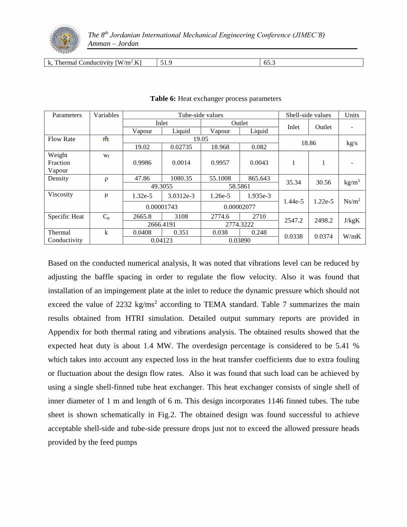
k, Thermal Conductivity [W/m2.K] 51.9 65.3
Table 6: Heat exchanger process parameters
Parameters Variables Tube-side values Shell-side values Units
Inlet Outlet Inlet Outlet -
Vapour Liquid Vapour Liquid
Flow Rate 19.05 18.86 kg/s
19.02 0.02735 18.968 0.082
Weight
Fraction
Vapour
wf
0.9986 0.0014 0.9957 0.0043 1 1 -
Density ρ 47.86 1080.35 55.1008 865.643 35.34 30.56 kg/m3
49.3055 58.5861
Viscosity μ 1.32e-5 3.0312e-3 1.26e-5 1.935e-3 1.44e-5 1.22e-5 Ns/m2
0.00001743 0.00002077
Specific Heat Cp 2665.8 3108 2774.6 2710 2547.2 2498.2 J/kgK
2666.4191 2774.3222
Thermal
Conductivity
k 0.0408 0.351 0.038 0.248 0.0338 0.0374 W/mK
0.04123 0.03890
Based on the conducted numerical analysis, It was noted that vibrations level can be reduced by
adjusting the baffle spacing in order to regulate the flow velocity. Also it was found that
installation of an impingement plate at the inlet to reduce the dynamic pressure which should not
exceed the value of 2232 kg/ms2 according to TEMA standard. Table 7 summarizes the main
results obtained from HTRI simulation. Detailed output summary reports are provided in
Appendix for both thermal rating and vibrations analysis. The obtained results showed that the
expected heat duty is about 1.4 MW. The overdesign percentage is considered to be 5.41 %
which takes into account any expected loss in the heat transfer coefficients due to extra fouling
or fluctuation about the design flow rates. Also it was found that such load can be achieved by
using a single shell-finned tube heat exchanger. This heat exchanger consists of single shell of
inner diameter of 1 m and length of 6 m. This design incorporates 1146 finned tubes. The tube
sheet is shown schematically in Fig.2. The obtained design was found successful to achieve
acceptable shell-side and tube-side pressure drops just not to exceed the allowed pressure heads
provided by the feed pumps

The 8th Jordanian International Mechanical Engineering Conference (JIMEC’8) Amman – Jordan
Table 7: Heat exchanger Output Summary generated from HTRI
Shell-side inlet pressure 4204.5 kPa
Tube-side inlet pressure 6501.5 kPa
Shell-side pressure drop, total/allowed 34.086 / 48.263 kPa
Tube-side pressure drop, total/allowed 15.321 / 48.263 kPa
Tube-side inlet velocity 4.22 m/s
Tube-side outlet velocity 3.72 m/s
Shell-side average film coefficient 902.77 W/m2K
Tube-side average film coefficient 1189.72 W/m2K
Overall Heat transfer coefficient, required/actual 140.12 / 147.70 W/m2K
Heat duty 1.3969 MW
Total area 1118.98 m2
Effective area 1105.58 m2/shell
Impingement diameter/nozzle 1.1
Crosspasses 13
Central baffle spacing 408.769 mm
Inlet baffle spacing 674.850 mm
Outlet baffle spacing 594.039 mm
Baffle thickness 6.350 mm
Effective length 5.765 m
Baffle-to-shell diametral clearance 6.3500 mm
Bundle-to-shell diametral clearance 14.1425 mm
Tube-to-baffle 0.7938 mm
Tube internal diameter 10.210 mm
Outer tube limit diameter 985.857 mm
Centre line tube diameter 969.982 mm
Equivalent projected diameter 13.604 mm
Diameter over fins 15.596 mm
Fin root diameter 12.700 mm
Wall thickness under fins 1.245 mm
Tubecount 1146
Overdesign 5.41 %

The 8th Jordanian International Mechanical Engineering Conference (JIMEC’8) Amman – Jordan
Fig. 2: Tubesheet layout
4.2 Thermal model results
In order to verify the accuracy of the thermal model derived in section 3, the thermal system equations
were solved numerically for the purpose of determining the heat transfer coefficients and the required heat
transfer area for the subject heat exchanger. In order to compare the mathematical model and HTRI
simulation results, the input parameters were used as common according to Table 4, 5 and 6. The solution
involved estimation of the correction factors listed in Table 2, followed by determining the shell-side and
tube-side heat transfer coefficients. Finally, the overall heat transfer coefficient was calculated to estimate
the required area of heat transfer using effectiveness-NTU method. An overall summary of the main
output results extracted from the mathematical model is shown in Table 8. A comparison study between
the main thermal model results and the corresponding ones resulted from HTRI simulation was
conducted. Fig.3 shows the estimated heat transfer area for the thermal model and HTRI rating. It was
found that the proposed mathematical thermal model was able to predict the required heat transfer area
accurately with percentage of error didn’t exceed 2.6 % in comparison with HTRI results. Moreover, the
relatively larger area predicted from the mathematical model can accommodate few fluctuations in the
operating conditions and fouling rates. Fig. 4 shows the effect of increasing the fouling factor on both
shell and tube sides in lowering the overall heat transfer coefficients.
Table 8: Thermal model results

The 8th Jordanian International Mechanical Engineering Conference (JIMEC’8) Amman – Jordan
Tube-Side Shell-Side
Prantdle No., Pr 0.952 Prantdle No., Pr 0.95
Reynolds No.,Re 108535.5 Reynolds No.,Re
34541
Nusselt No., Nu 242.01 Baffle Cut 1.133
Tube-side convective heat transfer
coefficient,αt (W/m2K) 949.75 Baffle Leakage 1.089
Fouling (m2 K/W) 0.000176 Baffle Bypass 1.043
Effectiveness,ε 0.785 Unequal Baffle Spacing 0.795
NTU 3.3 Wall Viscosity 0.997
Overall finned tubes area(m2) 1132 Shell-side convective heat transfer
coefficient,αt (W/m2K 495.16
Fig. 3: Heat transfer area generated by thermal model and HTRI Simulation

The 8th Jordanian International Mechanical Engineering Conference (JIMEC’8) Amman – Jordan
185
190
195
200
205
210
215
0 0.0002 0.0004 0.0006
Fouling/m2KW-1
Ove
rall
He
at T
ran
sfe
r C
oe
ffic
ien
t/W
m-2
K-1
Tube-side
Shell-lside
Fig. 4: Effects of tube-side and shell-side fouling on the overall heat transfer coefficients
Fig. 5 shows a comparison between mathematical and HTRI models in terms of the heat transfer
coefficients. It was found that the tube-side and shell-side heat transfer coefficients resulted from the
mathematical model are higher than the corresponding one generated by HTRI rating by 24 % and 40 %,
respectively. The obtained findings indicate that Dittus- Boelter correlation was able to predict the tube-
side heat coefficient efficiently. On the other hand, it was observed that Bell-Delaware method cannot
capture the shell-side heat transfer coefficient accurately. This is due to the complex flow regime on the
shell side which combines both cross and axial flow and subjected to fluctuations at the inlet and exit
nozzles and near the baffles. Furthermore, the mathematical model is still sufficient as it can predict the
heat transfer area with more conservative values of the heat transfer coefficients.
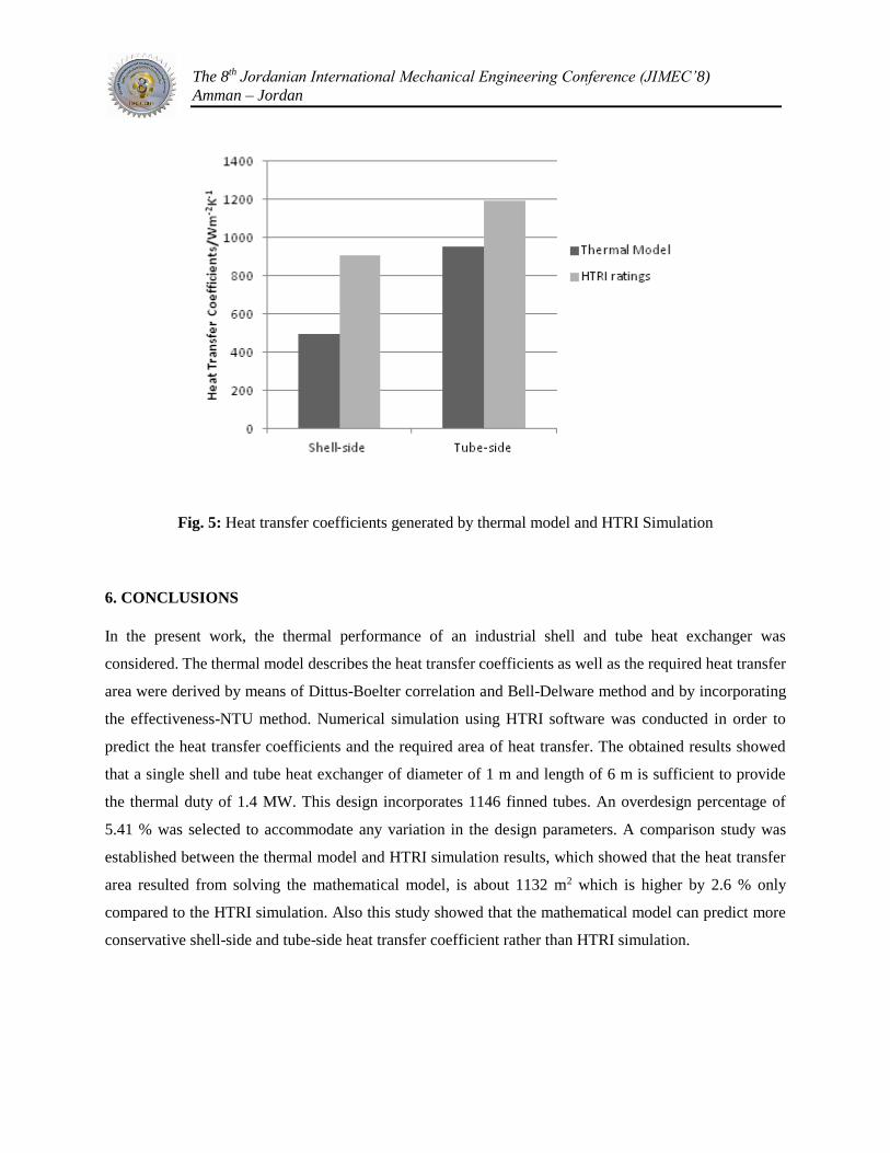
The 8th Jordanian International Mechanical Engineering Conference (JIMEC’8) Amman – Jordan
Fig. 5: Heat transfer coefficients generated by thermal model and HTRI Simulation
6. CONCLUSIONS
In the present work, the thermal performance of an industrial shell and tube heat exchanger was
considered. The thermal model describes the heat transfer coefficients as well as the required heat transfer
area were derived by means of Dittus-Boelter correlation and Bell-Delware method and by incorporating
the effectiveness-NTU method. Numerical simulation using HTRI software was conducted in order to
predict the heat transfer coefficients and the required area of heat transfer. The obtained results showed
that a single shell and tube heat exchanger of diameter of 1 m and length of 6 m is sufficient to provide
the thermal duty of 1.4 MW. This design incorporates 1146 finned tubes. An overdesign percentage of
5.41 % was selected to accommodate any variation in the design parameters. A comparison study was
established between the thermal model and HTRI simulation results, which showed that the heat transfer
area resulted from solving the mathematical model, is about 1132 m2 which is higher by 2.6 % only
compared to the HTRI simulation. Also this study showed that the mathematical model can predict more
conservative shell-side and tube-side heat transfer coefficient rather than HTRI simulation.

The 8th Jordanian International Mechanical Engineering Conference (JIMEC’8) Amman – Jordan
NOMENCLATURE
Ds Shell internal diameter Dof Diameter over fins
Di Tube internal diameter Dfr Fin root diameter
Dt Tube external diameter Dreq Equivalent projected diameter
Dti Internal diameter at fin area Lfh Fin height
Ltp Tube pitch Lfs Fin thickness
Lpp Tube pitch parallel to direction of flow Twf Wall thickness under fins
t Tube thickness Lbb Bypass channel diametral gap
L Tube length Lbch Baffle cut height
Le Effective length Lsb Baffle to shell diametric clearance
Nt Number of tubes Ltb Tube to baffle diametric clearance
Nf Fin density (no. of fins/meter) Lbc Central baffle spacing
Lbi Inlet baffle spacing Ntcw Number of tube rows crossed in
window area
Lbo Outlet baffle spacing T Bulk temperature
Dotl Outer tube limit diameter Twall Wall temperature
Dctl Centerline tube limit diameter JI Heat transfer factor
Bc Baffle cut Ao Heat transfer area
JC Baffle cut correction factor Aof Wetted surface area of finned tube
per unit length of tube
JL Baffle leakage correction factor th Head thickness
JB Bundle bypass correction factor ts Shell thickness
JS Unequal baffle spacing correction
factor
Rs Shell radius
JR Laminar flow correction factor Dh Head Diameter
Jμ Wall viscosity correction factor Flow rate
α Heat transfer coefficient wf Weight fraction
αi Ideal tube bank heat transfer
coefficient
ρ Density
FW Fraction of cross-sectional area
occupied by window
Cp Heat Capacity
ϴctl Baffle cut angle relative to center line k Thermal conductivity
Ssb Shell-to-baffle leakage area T Bulk temperature
Stb Tube-to-baffle leakage area Twall Wall temperature
Sm Cross-flow area at tube bundle
centerline
P Internal pressure
ϴds Baffle cut angle σts Tensile strength
Fsbp Bypass to cross-flow area ratio σys Yield stress
Sb Bypass area εme Elastic modulus
Nss Number of sealing strip pairs
Ntcc Number of tube rows passed between
baffle tips
Subscripts
rss Ratio of Nss to Ntcc i Inlet

The 8th Jordanian International Mechanical Engineering Conference (JIMEC’8) Amman – Jordan
Lpl Width of bypass lane between tubes o Outlet
Nb Number of baffle compartments t Tube-side
Nc Total number of tube rows crossed by
flow
s Shell-side
NTU No. of Transfer Units h Hot stream
ε effectiveness c Cold stream

The 8th Jordanian International Mechanical Engineering Conference (JIMEC’8) Amman – Jordan
ACKNOWLEDGEMENTS
The author is grateful for the support provided by Heriot-Watt University-Dubai Campus. Also Many
thanks to Exterran team for providing technical data used in the analysis of heat exchangers.
REFERENCES
1. Serna M. and Jimenez A., (2005), “A compact formulation of the Bell-Delaware method for
heat exchanger design and optimization”, Trans IChemE, 83(A), 539-550.
2. Serna M. and Jimenez A., (2004), “An efficient method for the design of shell and tube Heat
exchanger”, Heat Transfer Engineering, 25(2), 5-16.
3. Barman J. and Ghoshal A., (2007), “Performance analysis of finned tube and unbaffled
shell-and-tube heat exchangers”, International Journal of Thermal Sciences, 46, 1311-1317.
4. Shinde S., Pancha M., (2012), “Comparative thermal performance analysis of segmental
baffle heat exchanger with continuous helical baffle heat exchanger using Kern method”,
International Journal of Engineering Research and Applications, 2, 2264-2271.
5. Ghaith F., (2012), “Thermal design of heat exchangers, B51 GU: Heat Transfer and Heat
Exchangers”, Heriot-Watt University, Dubai Campus.
6. Hosseini R., Hosseini-Ghaffar A., Soltani M., (2007), “Experimental determination of shell
side heat transfer coefficient and pressure drop for an oil cooler shell-and-tube heat exchanger
with three different tube bundles”, Applied Thermal Engineering, 27, 1001-1008.
7. Fabbri G., (2000), “Heat transfer optimization in corrugated wall channels”, International
Journal of Heat and Mass Transfer, 43, 4299-4310.
8. Shale gas Wiki, (2010), Chemical Composition of Natural Gas, shalegaswiki.com, Retrieved
March 13, 2013, from
http://www.shalegaswiki.com/index.php/Chemical_Composition_of_Natural_Gas
9. Taborek J., Afgan N., (1983), Heat exchangers—theory and practice, Hemisphere Publishing
Corp., Washington, D.C.
10. John R. Thome, (2004), Wolverine Engineering Data Book III, Wolverine Tube, Inc.

The 8th Jordanian International Mechanical Engineering Conference (JIMEC’8) Amman – Jordan

The 8th Jordanian International Mechanical Engineering Conference (JIMEC’8) Amman – Jordan
1.