
Jeffrey Cichonski Joshua M Franklin Michael Bartock https ... · NIST Special Publication 800-187 ....
49
NIST Special Publication 800-187 Guide to LTE Security Jeffrey Cichonski Joshua M. Franklin Michael Bartock This publication is available free of charge from: https://doi.org/10.6028/NIST.SP.800-187 C O M P U T E R S E C U R I T Y
Transcript of Jeffrey Cichonski Joshua M Franklin Michael Bartock https ... · NIST Special Publication 800-187 ....
NIST Special Publication 800-187
Guide to LTE Security Jeffrey Cichonski
Joshua M. Franklin Michael Bartock
This publication is available free of charge from: https://doi.org/10.6028/NIST.SP.800-187
C O M P U T E R S E C U R I T Y

NIST Special Publication 800-187
Guide to LTE Security
Jeffrey Cichonski Joshua M. Franklin
Applied Cybersecurity Division Information Technology Laboratory
Michael Bartock
Computer Security Division Information Technology Laboratory
This publication is available free of charge from: https://doi.org/10.6028/NIST.SP.800-187
December 2017
U.S. Department of Commerce Wilbur L. Ross, Jr., Secretary
National Institute of Standards and Technology
Walter Copan, NIST Director and Under Secretary of Commerce for Standards and Technology

Authority
This publication has been developed by NIST in accordance with its statutory responsibilities under the Federal Information Security Modernization Act (FISMA) of 2014, 44 U.S.C. § 3551 et seq., Public Law (P.L.) 113-283. NIST is responsible for developing information security standards and guidelines, including minimum requirements for federal information systems, but such standards and guidelines shall not apply to national security systems without the express approval of appropriate federal officials exercising policy authority over such systems. This guideline is consistent with the requirements of the Office of Management and Budget (OMB) Circular A-130.
Nothing in this publication should be taken to contradict the standards and guidelines made mandatory and binding on federal agencies by the Secretary of Commerce under statutory authority. Nor should these guidelines be interpreted as altering or superseding the existing authorities of the Secretary of Commerce, Director of the OMB, or any other federal official. This publication may be used by nongovernmental organizations on a voluntary basis and is not subject to copyright in the United States. Attribution would, however, be appreciated by NIST.
National Institute of Standards and Technology Special Publication 800-187 Natl. Inst. Stand. Technol. Spec. Publ. 800-187, 49 pages (December 2017)
CODEN: NSPUE2
This publication is available free of charge from: https://doi.org/10.6028/NIST.SP.800-187
Certain commercial entities, equipment, or materials may be identified in this document in order to describe an experimental procedure or concept adequately. Such identification is not intended to imply recommendation or endorsement by NIST, nor is it intended to imply that the entities, materials, or equipment are necessarily the best available for the purpose.
There may be references in this publication to other publications currently under development by NIST in accordance with its assigned statutory responsibilities. The information in this publication, including concepts and methodologies, may be used by federal agencies even before the completion of such companion publications. Thus, until each publication is completed, current requirements, guidelines, and procedures, where they exist, remain operative. For planning and transition purposes, federal agencies may wish to closely follow the development of these new publications by NIST.
Organizations are encouraged to review all draft publications during public comment periods and provide feedback to NIST. Many NIST cybersecurity publications, other than the ones noted above, are available at https://csrc.nist.gov/publications.
Comments on this publication may be submitted to: National Institute of Standards and Technology
Attn: Applied Cybersecurity Division, Information Technology Laboratory 100 Bureau Drive (Mail Stop 2000) Gaithersburg, MD 20899-2000
Email: [email protected]
All comments are subject to release under the Freedom of Information Act (FOIA).

NIST SP 800-187 GUIDE TO LTE SECURITY
ii
This publication is available free of charge from: https://doi.org/10.6028/N
IST.SP.800-187
Reports on Computer Systems Technology
The Information Technology Laboratory (ITL) at the National Institute of Standards and Technology (NIST) promotes the U.S. economy and public welfare by providing technical leadership for the Nation’s measurement and standards infrastructure. ITL develops tests, test methods, reference data, proof of concept implementations, and technical analyses to advance the development and productive use of information technology. ITL’s responsibilities include the development of management, administrative, technical, and physical standards and guidelines for the cost-effective security and privacy of other than national security-related information in federal information systems. The Special Publication 800-series reports on ITL’s research, guidelines, and outreach efforts in information system security, and its collaborative activities with industry, government, and academic organizations.
Abstract
Cellular technology plays an increasingly large role in society as it has become the primary portal to the internet for a large segment of the population. One of the main drivers making this change possible is the deployment of 4th generation (4G) Long Term Evolution (LTE) cellular technologies. This document serves as a guide to the fundamentals of how LTE networks operate and explores the LTE security architecture. This is followed by an analysis of the threats posed to LTE networks and supporting mitigations. Keywords
cellular security; networking; Long Term Evolution; 3rd Generation Partnership Project (3GPP); LTE; telecommunications; wireless.
Acknowledgments
The authors wish to thank all of the individuals who provided public comments, and their colleagues who reviewed drafts of this report and contributed to its technical content. This includes Tim Grance, Sheila Frankel, Sanjeev Sharma, Gema Howell, Michael Ogata, Nelson Hastings, Tracy McElvaney, and Murugiah Souppaya of NIST. The authors would like also recognize the technical contributions of the Canadian Telecom Cyber Protection (CTCP) Working Group. Finally, the authors would like to extend a special thanks to Alf Zugenmaier of the Munich University of Applied Sciences.
Audience
This document introduces high-level LTE concepts and discusses technical LTE security mechanisms in detail. Technical readers are expected to understand fundamental networking concepts and general network security. It is intended to assist those evaluating, adopting, and operating LTE networks, specifically telecommunications engineers, system administrators, cybersecurity practitioners, and security researchers.
Trademark Information
All product names are registered trademarks or trademarks of their respective companies.

NIST SP 800-187 GUIDE TO LTE SECURITY
iii
This publication is available free of charge from: https://doi.org/10.6028/N
IST.SP.800-187
Table of Contents
1 Introduction ............................................................................................................ 6
1.1 Purpose and Scope ........................................................................................ 6
1.2 Document Structure ........................................................................................ 6
1.3 Document Conventions ................................................................................... 7
2 Overview of LTE Technology ................................................................................ 8
2.1 Evolution of 3GPP Standards ......................................................................... 8
2.2 LTE Concepts ................................................................................................. 9
2.2.1 Mobile Devices ................................................................................... 10
2.2.2 E-UTRAN ........................................................................................... 11
2.2.3 Evolved Packet Core .......................................................................... 12
2.2.4 LTE Network Topologies .................................................................... 13
2.3 LTE Network Protocols ................................................................................. 14
2.4 LTE Bearers .................................................................................................. 16
2.5 UE Attach ...................................................................................................... 17
3 LTE Security Architecture ................................................................................... 19
3.1 Cryptographic Overview ................................................................................ 19
3.2 Hardware Security ........................................................................................ 21
3.3 UE Authentication ......................................................................................... 21
3.4 Air Interface Security ..................................................................................... 22
3.5 E-UTRAN Security ........................................................................................ 25
3.6 Backhaul Security ......................................................................................... 26
3.7 Core Network Security .................................................................................. 28
4 Threats to LTE Networks ..................................................................................... 29
4.1 General Cybersecurity Threats ..................................................................... 29
4.1.1 Malware Attacks on UE’s .................................................................... 29
4.1.2 Malware Attacks Impacting RAN Infrastructure .................................. 29
4.1.3 Malware Attacks Impacting Core Infrastructure .................................. 30
4.1.4 Unauthorized OAM Network Access .................................................. 30
4.2 Rogue Base Stations .................................................................................... 30
4.2.1 Device and Identity Tracking .............................................................. 31
4.2.2 Downgrade Attacks ............................................................................ 31

NIST SP 800-187 GUIDE TO LTE SECURITY
iv
This publication is available free of charge from: https://doi.org/10.6028/N
IST.SP.800-187
4.2.3 Preventing Emergency Phone Calls ................................................... 31
4.2.4 Unauthenticated REJECT Messages ................................................. 32
4.3 Air Interface Eavesdropping .......................................................................... 32
4.4 Attacks Via Compromised Femtocell ............................................................ 32
4.5 Radio Jamming Attacks ................................................................................ 33
4.5.1 Jamming UE Radio Interface .............................................................. 33
4.5.2 Jamming eNodeB Radio Interface ...................................................... 33
4.6 Backhaul and Core Eavesdropping............................................................... 33
4.7 Physical Attacks on Network Infrastructure ................................................... 33
4.8 Attacks Against K .......................................................................................... 34
4.9 Stealing Service ............................................................................................ 34
5 Mitigations ............................................................................................................ 35
5.1 Cybersecurity Industry Recommended Practices ......................................... 35
5.2 Enabling Confidentiality on the Air Interface ................................................. 35
5.3 Use of the Ciphering Indicator ...................................................................... 36
5.4 User-Defined Option for Connecting to LTE Networks .................................. 36
5.5 Ensure Confidentiality Protection of S1 Interface .......................................... 37
5.6 Encrypt Exposed Interfaces Between Core Network Components ............... 37
5.7 Use of SIM/USIM PIN Code .......................................................................... 37
5.8 Use of Temporary Identities .......................................................................... 37
5.9 3rd Party Over-the-Top Solutions .................................................................. 37
5.10 Unauthenticated Reject Message Behavior .................................................. 38
5.11 Physical Security of Cell Site Equipment ...................................................... 38
5.12 Rogue Base Station Detection ...................................................................... 38
6 Conclusions.......................................................................................................... 39
List of Appendices
Appendix A— Acronyms and Acronyms .................................................................. 41
Appendix B— References .......................................................................................... 44
List of Figures
Figure 1 - High-level Cellular Network ............................................................................. 9
Figure 2 - E-UTRAN ...................................................................................................... 11

NIST SP 800-187 GUIDE TO LTE SECURITY
v
This publication is available free of charge from: https://doi.org/10.6028/N
IST.SP.800-187
Figure 3 - LTE Network Architecture ............................................................................. 13
Figure 4 - LTE Protocol Stack ....................................................................................... 15
Figure 5 - Initial Attach .................................................................................................. 18
Figure 6 - Keys Protecting the Network Stack ............................................................... 20
Figure 7 - Authentication and Key Agreement Protocol ................................................. 22
Figure 8 - Highlighting the Air Interface ......................................................................... 23
Figure 9 - Integrity Protection Requirements ................................................................. 24
Figure 10 - Confidentiality Protection Requirements ..................................................... 24
Figure 11 - Protecting the S1 Interface .......................................................................... 26
Figure 12 - Sample Illustration of Security Gateways .................................................... 27
Figure 13 - Example Rogue Base Station ..................................................................... 30
Figure 14 – Simplified Downgrade Attack ..................................................................... 31
List of Tables
Table 1 - Cryptographic Key Information Summary ...................................................... 20

NIST SP 800-187 GUIDE TO LTE SECURITY
6
This publication is available free of charge from: https://doi.org/10.6028/N
IST.SP.800-187
This publication is available free of charge from: https://doi.org/10.6028/N
IST.SP.800-187
1 Introduction
Cellular technology has caused large changes throughout society in recent decades. Besides providing telephony services, cellular devices store and process personal information, provide enterprise connectivity, and act as the primary portal to the internet for many individuals. Phones, tablets, laptops, wearables, cellular modems in vehicles, and other industry specific equipment all have the ability to access cellular networks. The cellular infrastructure of the United States is transitioning from older 2nd Generation (2G) and 3rd Generation (3G) cellular technologies to newer 4th Generation (4G) technologies such as Long Term Evolution (LTE). LTE is now the dominant air interface technology across the United States and is seeing rapid adoption in countries across the globe.
1.1 Purpose and Scope
The purpose of this document is to provide information to organizations regarding the security capabilities of cellular networks based on LTE technology. LTE networks are rarely deployed in a standalone fashion and instead are integrated alongside the previous generations of cellular systems - however 3G and 2G networks are out of scope for the technology overview of this document. Because 2G and 3G networks are deployed alongside LTE networks, these older cellular systems are discussed within the threats and mitigations section of this document. The document is primarily scoped to analyzing the security of the systems traditionally owned and/or operated by a wireless provider, but also includes organizations writing firmware to operate the System on a Chip (SoC) inside of a mobile device that communicates with the cellular infrastructure. The wireless providers, also known as mobile network operators (MNOs), operate the cellular LTE air interface, backhaul, core network, and portions of a user’s mobile device, including the Universal Integrated Circuit Card (UICC) hardware token and the Universal Subscriber Identity Module (USIM) software application. All of these entities will be fully described within this document. The mobile device hardware, mobile operating system (e.g., Android, Blackberry, iOS, Windows Phone), and 3rd party mobile applications are generally out of the scope of this document unless otherwise noted. This document does not analyze non 3rd Generation Partnership Project (3GPP) networks (e.g., WiFi, WiMAX, 3GPP2), forthcoming 3GPP features such as device to device cellular communications and cellular internet of things (IoT), and the over-the-air (OTA) management updates to cellular platforms, and the networks supporting services (e.g Domain Name Services (DNS), Network Time Protocol (NTP)). Supply chain issues relating to cellular networks are also not described. Finally, the IP Multimedia Subsystem (IMS), a modern platform for delivering services such as Voice over LTE (VoLTE), is not included within this document.
1.2 Document Structure
The remainder of this document is organized into the following major sections: • Section 2 provides an overview of LTE standards and technology, • Section 3 details the security architecture of LTE, • Section 4 identifies threats to LTE networks,

NIST SP 800-187 GUIDE TO LTE SECURITY
7
This publication is available free of charge from: https://doi.org/10.6028/N
IST.SP.800-187
This publication is available free of charge from: https://doi.org/10.6028/N
IST.SP.800-187
• Section 5 recommends mitigations and other methods of enhancing LTE security, and • Section 6 contains conclusions and future research.
The document also contains appendices with supporting material: • Appendix A defines selected acronyms and abbreviations used in this publication, and • Appendix B contains a list of references used in the development of this document.
1.3 Document Conventions
This document primarily uses LTE/Evolved Packet System (EPS) terminology. Therefore, those already familiar with cellular concepts from non-LTE systems and terminology may need to consult the appendix containing Acronyms and Acronyms for clarification.
• The terms "cell" and "cellular" are used interchangeably. • The term "base station" is used as a standards agnostic term of referring to a cellular
tower communicating with a mobile device, and is often used when discussing the interaction between 2G, 3G, and 4G systems. Each set of standards uses a specific term for base station, and LTE employs the term evolved Node B, which is shortened to eNodeB or eNB. eNodeB is generally used in this document, but when standards are quoted or specific cryptographic keys referenced, the term eNB may be used.
• The term "mobile device" is used as a standards agnostic term of referring to the User Equipment (UE) (e.g., cellphone, tablet, cellular dongle).
• The LTE standards heavily use the term Evolved Packet System (EPS) which is used interchangeably with "LTE" within this document.
• The LTE standards heavily use the term Evolved Packet Core (EPC), which is used interchangeably with the term “core.”

NIST SP 800-187 GUIDE TO LTE SECURITY
8
This publication is available free of charge from: https://doi.org/10.6028/N
IST.SP.800-187
This publication is available free of charge from: https://doi.org/10.6028/N
IST.SP.800-187
2 Overview of LTE Technology
A cellular network is a wireless network with a distributed coverage area made up of cellular sites housing radio equipment. A cellular site is often owned and operated by a wireless telecommunications company, internet service provider, or possibly government entity. The wireless telecommunications company, or mobile network operator (MNO), providing service to end users may own the cellular site, or pay for access to the cellular infrastructure - as is the case with mobile virtual network operators (MVNO). MNOs distribute cellular radio equipment throughout a large geographic region, and connect them back to a backend core network they typically own and operate. In areas receiving poor cellular service, such as inside a building, MNOs may provide a signal booster or small-scale base station directly to the end user to operate. Before LTE, cellular systems were modeled after the traditional wireline telephony system in that a dedicated circuit was provided to a user making a telephone call, ensuring a minimal guarantee of service. In comparison to circuit switched cellular networks of the past, LTE networks utilize packet switching. An LTE network provides consistent Internet Protocol (IP) connectivity between an end user's mobile device and IP services on the data network, while maintaining connectivity when moving from tower to tower (e.g., mobility). LTE is a mobile broadband communication standard defined by the 3rd Generation Partnership Project (3GPP), a worldwide standards development organization. Implementations of LTE networks are being deployed across the globe and installations continue to increase as the demand for high-speed mobile networks is constantly rising. Within Technical Specification (TS) 22.278 [9], 3GPP defines a number of high-level goals for LTE systems to meet, including:
• Provide increased data speeds with decreased latency, • Build upon the security foundations of previous cellular systems, • Support interoperability between current and next generation cellular systems and other
data networks, • Improve system performance while maintaining current quality of service, and • Maintain interoperability with legacy systems.
The following sections explain the fundamental concepts of LTE technology and architecture, network protocols, and the evolution of the 3GPP security.
2.1 Evolution of 3GPP Standards
Global System for Mobile Communications (GSM) is a 2G circuit switched cellular technology. Although GSM was not initially defined by 3GPP, 3GPP took control of the standard to maintain, enhance, and use it as a foundation to make future developments. 3GPP's first extension of GSM was the General Packet Radio Service (GPRS), referred to as a 2.5G technology. GPRS was the first method of sending non-voice data over a cellular network, and was quickly followed by the Enhanced Data Rates for GSM Evolution (EDGE), sometimes referred to as a 2.75G technology.

NIST SP 800-187 GUIDE TO LTE SECURITY
9
This publication is available free of charge from: https://doi.org/10.6028/N
IST.SP.800-187
This publication is available free of charge from: https://doi.org/10.6028/N
IST.SP.800-187
The first voice standard defined by 3GPP was the Universal Mobile Telecommunications System (UMTS), which is a 3G circuit switched technology. Soon after the development of UMTS, 3GPP packet switched technologies were evolved into multiple variants collectively referred to as High Speed Packet Access (HSPA), which is arguably considered 3.5G, although certain mobile devices will display an HSPA connection as 4G. HSPA was created to increase data throughput on both the downlink and uplink connections. LTE needs to support a growing demand for higher data rates and quality of service. It also needs to be able to quickly support new advances in technology, and LTE’s packet switched foundation will make it easier to upgrade/update the technology as well as lower the complexity of the overall network. To meet these goals, LTE was introduced via 3GPP Release 8, which was frozen on December 11, 2008. All subsequent releases of LTE have built upon this baseline. 3GPP defines a series of specifications dedicated to the technological requirements for LTE, known as the 36 series. 3GPP also defines a series of specifications for security, known as the 33 series. Each 3GPP series is comprised of Technical Report (TR) and Technical Specification (TS) documents. Newly requested LTE features are explored via TRs in which possible solutions are propossed and evaluated. Once a single solution for the feature is agreed upon, it is standardized within a TS. This document is based on 3GPP Release 12, which was frozen on March 13, 2015 [1].
2.2 LTE Concepts
The following section describes important high level concepts and components of LTE networks that are used and discussed throughout the course of this document. One of the fundamental concepts to understand is the overall network architecture: mobile devices (UEs) connect to base stations that make up the E-UTRAN via radio signals, and the base stations transmit and receive IP packets to and from the core network. The core ntework has a large number of entry and exit points, including the internet and connections to other cellular networks. Figure 1 illustrates these high-level concepts.
Figure 1 - High-level Cellular Network
In contrast to earlier cellular network technologies that use a hybrid of circuit-switched technology for voice and packet-switched technology for data, LTE solely uses packet switched, IP-based technology. In the LTE architecture, voice traffic traverses the network over the data connection using protocols, such as VoLTE, which is similar to Voice Over IP (VoIP). VoLTE is being deployed with widespread adoption by MNOs in the US. MNOs still utilize legacy circuit

NIST SP 800-187 GUIDE TO LTE SECURITY
10
This publication is available free of charge from: https://doi.org/10.6028/N
IST.SP.800-187
This publication is available free of charge from: https://doi.org/10.6028/N
IST.SP.800-187
switched cellular networks to handle voice calls and short message service (SMS) messages by using a mechanism known as circuit switched fallback (CSFB).
2.2.1 Mobile Devices
Mobile devices are the primary endpoint in cellular networks, interacting with base stations via radio signals to send and receive information. A mobile device is composed of two distinct systems: the general purpose mobile OS (e.g., Android, iOS, Windows Phone) that users interact with and the telephony subsystem used to access the cellular network. The telephony subsystem contains a distinct application processor referred to as the baseband processor, which has its own operating system used to interact with the cellular network, often developed by the cellular SoC manufacturer. LTE standards refer to a mobile device as the UE, which refers to both the terminal with the mobile operating system, baseband processor, and LTE radio, and the removable hardware token housing security-critical information used to obtain network access. This removable hardware token is colloquially referred to as the SIM card, but LTE standards use the term Universal Integrated Circuit Card (UICC). The UICC, which is essentially a smartcard, runs a Java application known as the Universal Subscriber Identity Module (USIM). The USIM interfaces with the cellular radio and subsequently the mobile network. The UICC contains secret cryptographic keys that are shared with the MNO before it is provisioned to a user. There are two distinct identifiers used in cellular networks: The International Mobile Subscriber Identity (IMSI) and the International Mobile Equipment Identifier (IMEI). The IMSI is the long-term identity that the carrier uses to identify a subscriber. The IMEI is used to identify a specific mobile device to the network and is stored on a mobile device’s internal flash memory, although the IMEI may also be stored on the UICC.
The following is a consolidated list of the components included within the UE:
• User equipment (UE): Cellular device (cell phone, tablet, LTE modem, etc) includes the following:
o Mobile Equipment (ME): The mobile terminal without the hardware token. o UICC: A smart card that stores personal information, cryptographic keys, and is
responsible for running java applications that enable network access. This smart card is inserted into the ME.
o International Mobile Equipment Identifier (IMEI): Terminal identity used to identify the mobile device to the cellular network.
o International Mobile Subscriber Identity (IMSI): User identity used to identify a subscriber to the cellular network.
In addition to the IMEI and IMSI, MNO’s may utilize other LTE identities, including the Globally Unique Temporary Identity (GUTI) and the Temporary Mobile Subscriber Identity (TMSI). The GUTI can identify a UE to a network without having to send the long-term identity (i.e., IMSI). The security implications of clear-text transmission of the IMSI will be discussed in later sections. Different identities are used for various reasons, including limiting the exposure of

NIST SP 800-187 GUIDE TO LTE SECURITY
11
This publication is available free of charge from: https://doi.org/10.6028/N
IST.SP.800-187
This publication is available free of charge from: https://doi.org/10.6028/N
IST.SP.800-187
a permanent identity, to minimize tracking of a device as it accesses multiple services on the network.
2.2.2 E-UTRAN
The Radio Access Network (RAN) has evolved over time into the Evolved Universal Terrestrial Radio Access Network (E-UTRAN). UEs connect to the E-UTRAN to send data to the core network. The E-UTRAN is a mesh network composed of base stations. A base station, or Evolved Node B, modulates and demodulates radio signals to communicate with UEs. eNodeBs then act as a relay point to create and send IP packets to and from the core network. Cellular networks are designed to pass connectivity from one radio access device in the E-UTRAN to the next as the connected UE changes location. This seamless handoff ability allows devices to have a constant connection with minimal interruptions providing what is know as ‘mobility’ within cellular networks. eNodeBs use the X2 interface to communicate with each other, primarily transmitting control signaling to allow for LTE network communication enabling UE mobility. During this handover the serving eNodeB must transfer all UE context1, cellular paramaters and other information about the UE, to the receiving eNodeB. LTE uses a concept of named interfaces to easily identify the communication link between two endpoints. A named interface in LTE terminology, such as the X2 interface, refers to the logical link between two endpoints, and in this example two eNodeBs. Named interfaces in LTE are responsible for sending and receiving specified messages and data. These can be physically implemented in a variety of ways and multiple named interfaces can share the same physical connection. This physical connection can be a variety of network technologies such as fiber, Ethernet, microwave, satellite link, etc.
Figure 2 - E-UTRAN
Base stations come in a variety of form factors, different than a typical base station comprised of a physical cell tower and radio equipment. Small cells have a smaller form factor, transmit at lower power levels, capable of extending network coverage, and ultimately increase the capacity of the network.
1 UE Contexts are a data structure containing UE and User Identities, security parameters, and UE mobility state.

NIST SP 800-187 GUIDE TO LTE SECURITY
12
This publication is available free of charge from: https://doi.org/10.6028/N
IST.SP.800-187
This publication is available free of charge from: https://doi.org/10.6028/N
IST.SP.800-187
The following list consolidates this information:
• Evolved Universal Terrestrial Radio Access Network (E-UTRAN): All of the components providing wireless mobility.
o Evolved Node B (eNodeB or eNB): An evolved Node B, colloquially referred to as a base station.
o Small Cell: Low powered base station with less range and less capacity than a typical eNodeB, for instance Home eNodeBs (HeNB), Donor eNodeBs (DeNB), and Relay Nodes (RN).
2.2.3 Evolved Packet Core
The evolved packet core (EPC), illustrated in Figure 3, is the routing and computing brain of the LTE network. UEs receive control signals through base stations originating from the Mobility Management Entity (MME). The MME performs a large number of functions including managing and storing UE contexts, creating temporary identifiers, paging, controlling authentication functions, and selecting the Serving Gateway (S-GW) and Packet Data Network (PDN) Gateway (P-GW), respectively. No user traffic is sent through the MME. The S-GW anchors the UEs for intra-eNodeB handoffs and routes information between the P-GW and the E-UTRAN. The P-GW is the default router for the UE, making transfers between 3GPP and non-3GPP services, allocating IP addresses to UEs, and providing access to the PDN. The following list consolidates and defines the components included within the EPC:
• Evolved Packet Core (EPC): Routing and computing brain of the LTE network. o Mobility Management Entity (MME): Primary network signaling node that
does not interact with user traffic. Large variation in functionality including managing/storing UE contexts, creating temporary IDs, sending pages, controlling authentication functions, and selecting the S-GW and P-GWs.
o Serving Gateway (S-GW): Carries user data, anchors UEs for intra-eNodeB handoffs, and routes information between the P-GW and the E-UTRAN.
o Packet Data Network Gateway (P-GW): Allocates IP addresses, routes packets, and interconnects with non-3GPP networks.
o Home Subscriber Server (HSS): Master database with subscriber data and stores the secret key K.
o Authentication Center (AuC): Resides within the HSS, maps long term identities to pre-shared cryptographic keys, performs cryptographic calculations during authentication.
o Policy and Charging Rules Function (PCRF): Rules and policies related to quality of service (QoS), charging, and access to network resources are distributed to the P-GW and enforced by the PCRF.
o IP Multimedia Subsystem (IMS): Gateways to the public switched telephone network (PSTN), multimedia services (e.g., VoLTE, instant messaging, video), and paging for multimedia services.
o Backhaul: Connection between radio network and the core network. This connection can be fiber, satellite link, Ethernet cable, Microwave, etc.

NIST SP 800-187 GUIDE TO LTE SECURITY
13
This publication is available free of charge from: https://doi.org/10.6028/N
IST.SP.800-187
This publication is available free of charge from: https://doi.org/10.6028/N
IST.SP.800-187
o Packet Data Network (PDN): Any external IP network (e.g., internet). UEs can be connected to one or many PDNs at any point in time.
o Access Point Name (APN): Serves as the identifier for a PDN, and is the gateway between the EPC and PDN. The APN must be specified by the UE for each PDN it connects to.
Figure 3 depicts the components introduced above and shows the data flows between these network components. This graphic can serve as reference to visualize the interconnected fundamental LTE network components and may depict concepts not yet discussed. The solid lines in the diagram depict user traffic, while the dashed lines depict control signaling traffic.
2.2.4 LTE Network Topologies
An LTE network minimally consists of a UE, a group of eNodeBs and other radio access equipment making up the E-UTRAN and the backend core network controlled by the MNO. The E-UTRAN is connected to the EPC via a network link known as the backhaul. From a security perspective it is important to note the E-UTRAN and EPC are most likely in completely different geographic locations. Thus, the interfaces that link them may or may not be contained totally within the MNO’s private domain. This section will explore various operational network topologies such as fixed and deployable LTE networks.
A fixed LTE network is a typical implementation of a cellular network utilizing multiple cell sites to provide coverage to a large geographic area. In this type of architecture, the core network components are generally in separate locations. The cell sites that house the eNodeBs connect to the EPC through the backhaul. The backhaul connection can be provided by a multitude of technologies (e.g., microwave, satellite, fiber, etc). An MNO would typically deploy this type of network architecture. Although LTE networks require the same functional components in order to operate effectively, the quantity and placement of these components is completely dependent on the MNO’s network design. It is possible the network operator incorporates multiple EPC
Figure 3 - LTE Network Architecture
NIST SP 800-187 GUIDE TO LTE SECURITY
14
This publication is available free of charge from: https://doi.org/10.6028/N
IST.SP.800-187
This publication is available free of charge from: https://doi.org/10.6028/N
IST.SP.800-187
components that serve critical functions as well as load balances these components to provide increased availability. An example of a fixed LTE network is a large region being provided network coverage with the use of many spread out cell sites housing eNodeBs all connecting back into one or multiple EPCs. Multiple eNodeBs are interconnected through the X2 interface, which is responsible for session handover from one eNodeB to the next as the UE travels. Ultimately the components of the E-UTRAN are interconnected and communicate to the EPCs through the backhaul or S1 interface. There may be many to many relationships between the E-UTRANs and the EPCs to provide high availability and reliability. In contrast to a fixed LTE network, a deployable LTE network is a compact network able to be deployed in areas where no LTE coverage exists, or where coverage has been interrupted. The deployable network can be mobile and packaged in different form factors (e.g., mounted on a vehicle, trailer, backpack). These types of LTE architectures can be used to create a self-contained network or be connected to an existing LTE, or other, network. The hardware used in a deployable network is generally more compact and capable of handling only a fraction of the throughput and capacity of a fixed LTE network. A Cell on Wheels, or COW, is an example of a commercially available deployable LTE network. These COWs are environments that include all elements of an LTE network and are mounted on trailers or in some cases packaged onto vehicles. COWs often still need to be connected back to the core network. These types of deployables can be used to provide additional capacity to an existing network where there is an increased demand, for example a large sporting event. These can also be used where network coverage is not available, such as a natural disaster site, in order to provide first responders a means of communication. These deployable networks are commercially available and can be purchased from network equipment providers.
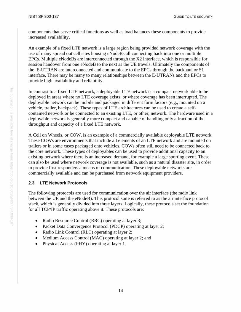
2.3 LTE Network Protocols
The following protocols are used for communication over the air interface (the radio link between the UE and the eNodeB). This protocol suite is referred to as the air interface protocol stack, which is generally divided into three layers. Logically, these protocols set the foundation for all TCP/IP traffic operating above it. These protocols are:
• Radio Resource Control (RRC) operating at layer 3; • Packet Data Convergence Protocol (PDCP) operating at layer 2; • Radio Link Control (RLC) operating at layer 2; • Medium Access Control (MAC) operating at layer 2; and • Physical Access (PHY) operating at layer 1.
NIST SP 800-187 GUIDE TO LTE SECURITY
15
This publication is available free of charge from: https://doi.org/10.6028/N
IST.SP.800-187
This publication is available free of charge from: https://doi.org/10.6028/N
IST.SP.800-187
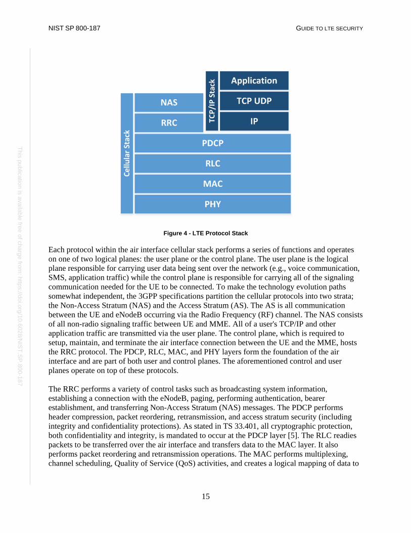
Figure 4 - LTE Protocol Stack
Each protocol within the air interface cellular stack performs a series of functions and operates on one of two logical planes: the user plane or the control plane. The user plane is the logical plane responsible for carrying user data being sent over the network (e.g., voice communication, SMS, application traffic) while the control plane is responsible for carrying all of the signaling communication needed for the UE to be connected. To make the technology evolution paths somewhat independent, the 3GPP specifications partition the cellular protocols into two strata; the Non-Access Stratum (NAS) and the Access Stratum (AS). The AS is all communication between the UE and eNodeB occurring via the Radio Frequency (RF) channel. The NAS consists of all non-radio signaling traffic between UE and MME. All of a user's TCP/IP and other application traffic are transmitted via the user plane. The control plane, which is required to setup, maintain, and terminate the air interface connection between the UE and the MME, hosts the RRC protocol. The PDCP, RLC, MAC, and PHY layers form the foundation of the air interface and are part of both user and control planes. The aforementioned control and user planes operate on top of these protocols. The RRC performs a variety of control tasks such as broadcasting system information, establishing a connection with the eNodeB, paging, performing authentication, bearer establishment, and transferring Non-Access Stratum (NAS) messages. The PDCP performs header compression, packet reordering, retransmission, and access stratum security (including integrity and confidentiality protections). As stated in TS 33.401, all cryptographic protection, both confidentiality and integrity, is mandated to occur at the PDCP layer [5]. The RLC readies packets to be transferred over the air interface and transfers data to the MAC layer. It also performs packet reordering and retransmission operations. The MAC performs multiplexing, channel scheduling, Quality of Service (QoS) activities, and creates a logical mapping of data to

NIST SP 800-187 GUIDE TO LTE SECURITY
16
This publication is available free of charge from: https://doi.org/10.6028/N
IST.SP.800-187
This publication is available free of charge from: https://doi.org/10.6028/N
IST.SP.800-187
the PHY layer. The PHY layer provides error management, signal processing, and modulates data onto and off of the air interface. The interfaces between the components within the E-UTRAN and the EPC have their own communication protocols, not listed here.
2.4 LTE Bearers
In LTE networks, connections must be established between endpoints before user traffic can be communicated; these connections are called bearers. A bearer is a connection between two endpoints that contains specific information about the traffic class, bit rate, delivery order, reliability, priority, and quality of service for its connection. A bearer may span multiple interfaces. It is important to note that there are two main types of bearers: signaling radio bearers and transport bearers. Signaling radio bearers are established on the control plane in order to allow signaling communication between the UE and eNodeB, and the eNodeB and MME. Transport bearers are established along the path of the user plane in order to allow transmission of user data to its desired endpoint. There are three signaling radio bearers that must be established which are solely used for the purpose of transmitting RRC and NAS messages [30]:
• Signaling Radio Bearer 0 (SRB0): SRB0 is responsible for establishing the RRC connection between the UE and eNodeB.
• Signaling Radio Bearer 1 (SRB1): SRB1 is responsible for the exchange of security information, measurement reports, fallback parameters, and handover information.
• Signaling Radio Bearer 2 (SRB2): SRB2 is responsible for the transferring of measurement information as well as NAS messages. SRB2 is always configured after the establishment of SRB1 and security activation.
Once the SRBs are set up, the UE is connected to the core network through a specific eNodeB, and is ready to transmit and receive user data. Throughout the LTE network there are multiple connection points (UE to eNodeB, eNodeB to S-GW, etc.) that user traffic must traverse. In order for user traffic to be allowed to traverse the LTE network multiple bearers must be established. For a UE to have full network connectivity the following bearers must be established in this order [29]:
• Data Radio Bearer (DRB): Established between the UE and eNodeB on the air interface (also referred to as the Uu interface). It allows direct user data communication between the UE and eNodeB.
• S1 Bearer: Established between the eNodeB and the appropriate S-GW on the S1-U interface.
• E-UTRAN Radio Access Bearer (E-RAB): This is a combination of the DRB and S1 Bearer and creates a connection between the UE and S-GW.
• S5/S8 Bearer: Established between S-GW and the appropriate P-GW for the user data plane.
• EPS Bearer: This is a combination of the E-RAB and the S5/S8 Bearer and provides user plane connectivity from the UE to the appropriate P-GW.

NIST SP 800-187 GUIDE TO LTE SECURITY
17
This publication is available free of charge from: https://doi.org/10.6028/N
IST.SP.800-187
This publication is available free of charge from: https://doi.org/10.6028/N
IST.SP.800-187
• External Bearer: Established between the P-GW and a resource external to the EPC that the UE needs to access, such as connectivity to the internet.
• End-to-End Service: This is a combination of the EPS Bearer and the External Bearer and allows user plane access from a UE to the appropriate resource that is external to the EPC.
Throughout the UE attach process, bearers are established on an as needed basis.
2.5 UE Attach
Before a UE can join an LTE network and access voice and data services, it must go through a procedure to identify itself to the LTE network. This process is known as the Initial Attach Procedure and handles the communication of identifiable information from the UE to the LTE EPC to ensure that the UE can access the network. If the process is successful, then the UE is provided default connectivity, with any charging rules that are applicable and enforced by the LTE network. The attach process is defined by TS 23.401 and is illustrated in Figure 5 below - General Packet Radio Service (GPRS) enhancements for E-UTRAN access [2]. The Initial Attach procedure begins with an attach request from the UE to the MME via the eNodeB. This request includes the IMSI, tracking information, cryptographic parameters, NAS sequencing number, and other information about the UE. The ATTACH REQUEST is sent as a NAS message. The eNodeB then forwards the ATTACH REQUEST along with information about the cell to which the UE is connected on to the MME. For each PDN that the UE connects to, a default EPS bearer is established to enable the always-on IP connectivity for the users and the UE during Network Attachment. If there are specific Policy and Charging Control rules in the PCRF for a subscriber or device for the default EPS bearer, they can be predefined in the P-GW and turned on in the attachment by the P-GW itself. During attachment, one or more Dedicated Bearer Establishment procedures may be launched to establish dedicated EPS bearer(s) for the specific UE. Also during the attach procedure, IP address allocation may be requested by the UE. The MME obtains the IMEI from the UE and checks it with an EIR (Equipment Identity Register), which may verify that this UE’s IMEI is not blacklisted. The MME then passes the IMEI software version to the HSS and P-GW. Once a UE has gone through the initial attach procedure it is assigned a GUTI by the MME. The GUTI is stored in both the UE and the MME and should be used when possible instead of the IMSI for future attach procedures for the specific UE.

NIST SP 800-187 GUIDE TO LTE SECURITY
18
This publication is available free of charge from: https://doi.org/10.6028/N
IST.SP.800-187
This publication is available free of charge from: https://doi.org/10.6028/N
IST.SP.800-187
Figure 5 - Initial Attach
Once the attach procedure is successfully completed, the UE authenticates via the Authentication and Key Agreement (AKA) protocol defined in section 3.3.

NIST SP 800-187 GUIDE TO LTE SECURITY
19
This publication is available free of charge from: https://doi.org/10.6028/N
IST.SP.800-187
This publication is available free of charge from: https://doi.org/10.6028/N
IST.SP.800-187
3 LTE Security Architecture
This section describes in further detail the authentication, cryptographic protection mechanisms, hardware protection mechanisms, and network protections LTE provides. A high level discussion of LTE security goals is provided within [9] and an understanding of 3GPP’s rationale for making certain security decisions and assumptions is recorded within [7]. The majority of technical security requirements are available within the primary LTE security specification – 3GPP TS 33.401 – EPS Security Architecture [5].
3.1 Cryptographic Overview
In older 2G cellular systems, the cryptographic algorithms used to secure the air interface and perform subscriber authentication functions were not publicly disclosed. The GSM algorithm families pertinent to our discussion are A3, A5, and A8. A3 provides subscriber authentication, A5 provides air interface confidentiality, and A8 is related to A3, in that it provides subscriber authentication functions, but within the SIM card. UMTS introduced the first publicly disclosed cryptographic algorithms used in commercial cellular systems. The terms UEA (UMTS Encryption Algorithm) and UIA (UMTS Integrity Algorithm) are used within UMTS as broad categories. UEA1 is a 128-bit block cipher called KASUMI, which is related to the Japanese cipher MISTY. UIA1 is a message authentication code (MAC), also based on KASUMI. UEA2 is a stream cipher related to SNOW 3G, and UIA2 computes a MAC based on the same algorithm [27]. LTE builds upon the lessons learned from deploying the 2G and 3G cryptographic algorithms. LTE introduced a new set of cryptographic algorithms and a significantly different key structure than that of GSM and UMTS. There are 3 sets of cryptographic algorithms for both confidentiality and integrity termed EPS Encryption Algorithms (EEA) and EPS Integrity Algorithms (EIA). EEA1 and EIA1 are based on SNOW 3G, very similar to algorithms used in UMTS. EEA2 and EIA2 are based on the Advanced Encryption Standard (AES) with EEA2 defined by AES in CTR mode (e.g., stream cipher) and EIA2 defined by AES-CMAC (Cipher-based MAC). EEA3 and EIA3 are both based on a Chinese cipher ZUC [5]. While these new algorithms have been introduced in LTE, network implementations commonly include older algorithms for backward compatability for legacy devices and cellular deployments. Many keys in LTE are 256-bits long, but in some current implementations only the 128 least significant bits are used. The specification has allowed for a system-wide upgrade from 128-bit to 256-bit keys.2 In LTE, the control and user planes may use different algorithms and key sizes. Figure 6 depicts the various keys alongside their use for an appropriate protocol.
2 3GPP 33.401 Section 6.1 a [7]

NIST SP 800-187 GUIDE TO LTE SECURITY
20
This publication is available free of charge from: https://doi.org/10.6028/N
IST.SP.800-187
This publication is available free of charge from: https://doi.org/10.6028/N
IST.SP.800-187
Figure 6 - Keys Protecting the Network Stack
The following table depicts various LTE key sizes and the other keys in the key hierarchy from which they are derived [5]. 3
Table 1 - Cryptographic Key Information Summary
Key Name Length (bits) Derived in Part From K Master Key 128 N/A: Pre-shared root
key
IK Integrity Key 128 K
CK Cipher Key 128 K
KASME MME Base Key 256 CK, IK
NH Next Hop 256 KASME
KeNB* eNB Handover Key 256 KASME, KeNB
KeNB eNB Base Key 256 KASME, NH
KNASint NAS Integrity Key 128 KASME
KNASenc NAS Confidentiality Key 128 KASME
RRCenc RRC Confidentiality Key 128 KeNB, NH
3 3GGP TS 33.401 Figure 6.2-2
NIST SP 800-187 GUIDE TO LTE SECURITY
21
This publication is available free of charge from: https://doi.org/10.6028/N
IST.SP.800-187
This publication is available free of charge from: https://doi.org/10.6028/N
IST.SP.800-187
RRCint RRC Integrity Key 128 KeNB, NH
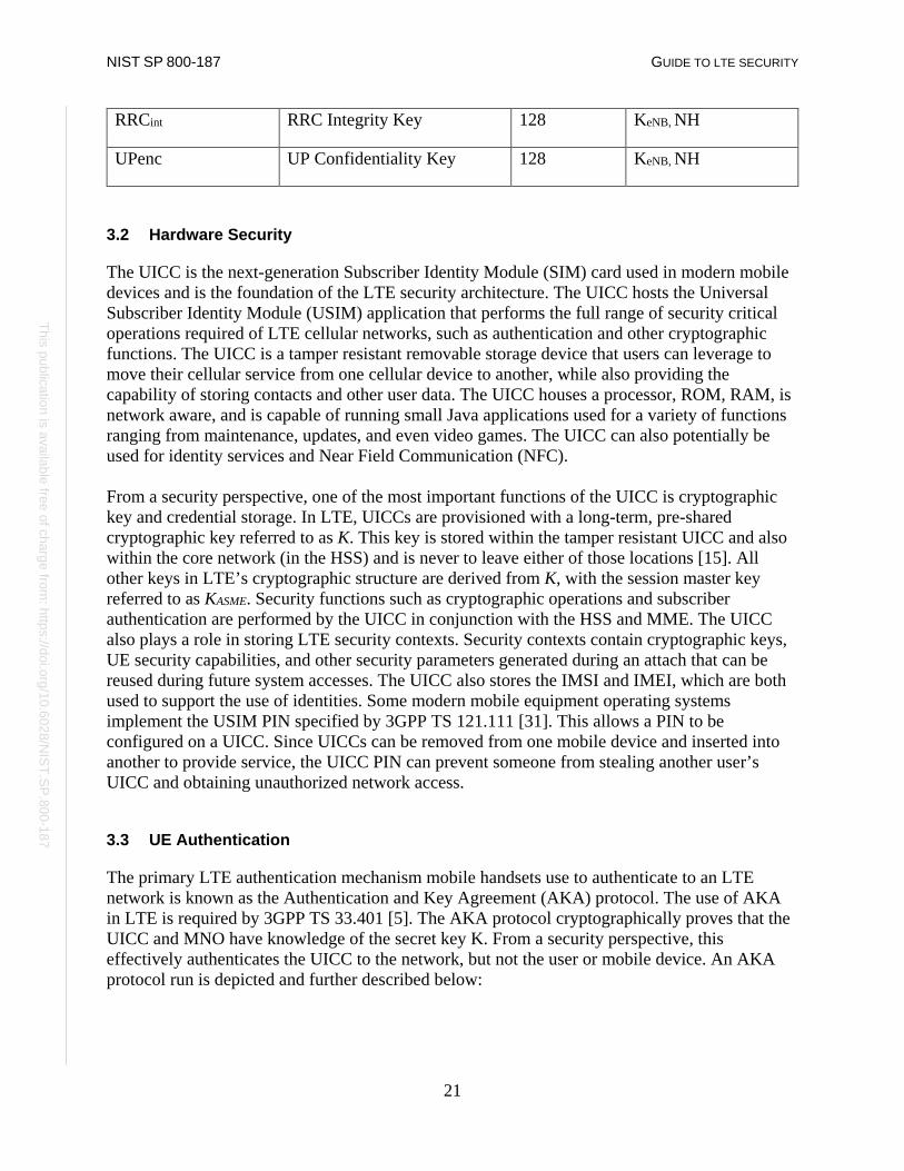
UPenc UP Confidentiality Key 128 KeNB, NH
3.2 Hardware Security
The UICC is the next-generation Subscriber Identity Module (SIM) card used in modern mobile devices and is the foundation of the LTE security architecture. The UICC hosts the Universal Subscriber Identity Module (USIM) application that performs the full range of security critical operations required of LTE cellular networks, such as authentication and other cryptographic functions. The UICC is a tamper resistant removable storage device that users can leverage to move their cellular service from one cellular device to another, while also providing the capability of storing contacts and other user data. The UICC houses a processor, ROM, RAM, is network aware, and is capable of running small Java applications used for a variety of functions ranging from maintenance, updates, and even video games. The UICC can also potentially be used for identity services and Near Field Communication (NFC). From a security perspective, one of the most important functions of the UICC is cryptographic key and credential storage. In LTE, UICCs are provisioned with a long-term, pre-shared cryptographic key referred to as K. This key is stored within the tamper resistant UICC and also within the core network (in the HSS) and is never to leave either of those locations [15]. All other keys in LTE’s cryptographic structure are derived from K, with the session master key referred to as KASME. Security functions such as cryptographic operations and subscriber authentication are performed by the UICC in conjunction with the HSS and MME. The UICC also plays a role in storing LTE security contexts. Security contexts contain cryptographic keys, UE security capabilities, and other security parameters generated during an attach that can be reused during future system accesses. The UICC also stores the IMSI and IMEI, which are both used to support the use of identities. Some modern mobile equipment operating systems implement the USIM PIN specified by 3GPP TS 121.111 [31]. This allows a PIN to be configured on a UICC. Since UICCs can be removed from one mobile device and inserted into another to provide service, the UICC PIN can prevent someone from stealing another user’s UICC and obtaining unauthorized network access.
3.3 UE Authentication
The primary LTE authentication mechanism mobile handsets use to authenticate to an LTE network is known as the Authentication and Key Agreement (AKA) protocol. The use of AKA in LTE is required by 3GPP TS 33.401 [5]. The AKA protocol cryptographically proves that the UICC and MNO have knowledge of the secret key K. From a security perspective, this effectively authenticates the UICC to the network, but not the user or mobile device. An AKA protocol run is depicted and further described below:

NIST SP 800-187 GUIDE TO LTE SECURITY
22
This publication is available free of charge from: https://doi.org/10.6028/N
IST.SP.800-187
This publication is available free of charge from: https://doi.org/10.6028/N
IST.SP.800-187
Figure 7 - Authentication and Key Agreement Protocol
The AKA procedure occurs as part of the UE attach process, described in Section 3.3, and provides mutual authentication between the UICC and the LTE network. AKA is begun by a UE providing its identifier to the appropriate MME (item 1 above). This identifier may be permanent, as is the case with the IMSI, or may be temporary. Examples of temporary identifiers include the Temporary Mobile Subscriber Identity (TMSI) and Globally Unique Temporary UE Identity (GUTI). After the identifier is provided to the core network, the MME provides the identifier, alongside additional cryptographic parameters and the serving network ID (SN id), to the HSS/AuC (item 2 above) these values then are used to generate an authentication vector (AUTN). To compute an AUTN, the HSS/AuC needs to use a random nonce (RAND), the secret key K, and a Sequence Number (SQN) as inputs to a cryptographic function. This function produces two cryptographic parameters used in the derivation of future cryptographic keys, alongside the expected result (XRES) and authentication token (AUTN) (item 3 above). This authentication vector is passed back to the MME for storage (item 4 above). In addition, the MME provides the AUTN and RAND to the UE, which is then passed to the USIM application (item 5 above). The USIM sends AUTN, RAND, the secret key K, and its SQN through the same cryptographic function used by the HSS/AuC (item 6 above). The result is labeled as RES, which is sent back to the MME (item 7 above). If the XRES value is equal to the RES value, authentication is successful and the UE is granted access to the network (item 8 above).
3.4 Air Interface Security
The UE and the eNodeB communicate using a Radio Frequency (RF) connection commonly referred to as the air interface, which is referred to as the Uu interface. Both endpoints modulate

NIST SP 800-187 GUIDE TO LTE SECURITY
23
This publication is available free of charge from: https://doi.org/10.6028/N
IST.SP.800-187
This publication is available free of charge from: https://doi.org/10.6028/N
IST.SP.800-187
IP packets into an RF signal that is communicated over-the-air interface; these devices then demodulate the RF signal into IP packets understandable by both the UE and EPC. The eNodeB routes these packets through the EPC while the UE uses the IP packets to perform some function. These radio waves are sent from a UE’s antenna over-the-air until they reach the antenna of the eNodeB.This over-the-air communication is not necessarily private, meaning anything within the wave path can intercept these radio waves. The figure below illustrates where in the network this is occurring.
Figure 8 - Highlighting the Air Interface
3GPP’s technical specification 33.401 directs that both the NAS and RRC control plane messages must be integrity protected. 3GPP TS 33.401 5.1.4.1 requires that “Integrity protection, and replay protection, shall be provided to NAS and RRC-signaling.” It is specified that user plane packets traveling on the Uu interface are not integrity protected. Specifically, 3GPP TS 33.401 5.1.4.1 states “User plane packets between the eNodeB and the UE shall not be integrity protected on the Uu interface.” Both control plane and user plane packets communicating between the UE and eNodeB on the Uu can be confidentiality protected but this is left as optional. This statement is based on a requirement located in 3GPP TS 33.401 5.1.4.1: “User plane confidentiality protection shall be done at PDCP layer and is an operator option.” Air interface confidentiality provides a higher level of assurance that messages being sent over the air cannot be deciphered by an external entity. LTE specifies a ciphering indicator feature in 3GPP TS 22.101 [6]; this feature is designed to give the user visibility into the status of the access network encryption. Unfortunately, this feature is not widely implemented in modern mobile phone operating systems. Figure 9 and Figure 10 help to illustrate where on the network integrity and encryption are provided by LTE.

NIST SP 800-187 GUIDE TO LTE SECURITY
24
This publication is available free of charge from: https://doi.org/10.6028/N
IST.SP.800-187
This publication is available free of charge from: https://doi.org/10.6028/N
IST.SP.800-187
Figure 9 - Integrity Protection Requirements
Figure 10 - Confidentiality Protection Requirements
An exact order is not specified for when the LTE network must negotiate security parameters for a given connection. The TS 24.301 [10] permits the following 7 messages to be sent without security protection:
• IDENTITY REQUEST (if requested identification parameter is IMSI); • AUTHENTICATION REQUEST; • AUTHENTICATION REJECT; • ATTACH REJECT; • DETACH ACCEPT (For non switch off); • TRACKING AREA UPDATE REJECT; • SERVICE REJECT.
When a message that requires protection needs to be sent the network must establish security parameters and agree on algorithms. This establishment is initiated by the sending of the Security Mode Command (SMC). The SMC dictates that the UE and serving network must initiate a cryptographic algorithm negotiation in order to select appropriate algorithms for: RRC ciphering and integrity protection on the Uu interface, user plane cyphering on the Uu interface, and NAS

NIST SP 800-187 GUIDE TO LTE SECURITY
25
This publication is available free of charge from: https://doi.org/10.6028/N
IST.SP.800-187
This publication is available free of charge from: https://doi.org/10.6028/N
IST.SP.800-187
cyphering and NAS integrity protection between UE and MME. It is important to note that the network selects the algorithm based upon security capabilities of the UE and a configured list of available security capabilities on the serving network. Separate Access Stratum (AS) and Non Access Stratum (NAS) level SMC procedures are required to configure security on each applicable portion of the protocol stack. The AS SMC is used for configuring RRC and user plane level protections, while the NAS SMC is used for configuring NAS level protections. Once an AKA run has occurred, and the NAS and optionally the AS SMCs are sent, a security context is generated. A security context is a collection of session keys and parameters used to protect either the NAS or AS. Long term information such as K, or other identifiers like the IMEI and IMSI are not stored within a security context. Typically, only the keys from KASME and downward within the key hierarchy are stored. When a UE deregisters from an eNodeB, the previous security context can be reused, avoiding a superfluous AKA run, which may add network congestion and require additional computing power on behalf of the core network.
3.5 E-UTRAN Security
The radio access network and associated interfaces make up the E-UTRAN portion of the LTE network, and which is the midway between a handset and an MNO’s core network. Handover is one of the most important functions of a cellular network. This allows the user the ability to be moving, such as traveling on a highway, and maintain call connection. Base stations will often need to communicate between themselves to enable this “mobility,” and they do so via the X2 interface. 3GPP specifies multiple security mechanisms to ensure a secure handoff of call related information. Two types of handovers exist: X2 handover and S1 handover. During an S1 handover the MME is aware that a handover is going to occur before it happens. Within an X2 handover, the MME is unaware and the transition occurs purely between eNodeBs via the X2 interface. There are unique security considerations for both methods of handover. With an S1 handover, the MME can refresh the cryptographic parameters used to protect the air interface before the connection is severed. With an X2 handover, fresh keying material can only be provided after the handover for use in the next handover. When handover occurs, new keys are generated, partly separating the new session from the previous one, although a new master session key (i.e., KASME) is not generated. The KeNB is used, alongside other cryptographic parameters and the cell ID of the new eNodeB, to generate KeNB*,
which is used to protect the new session after handover occurs. It is of note that the source base station and MME control key derivation and the new eNodeB is not meant have knowledge of the keys used in the original eNodeB session.

NIST SP 800-187 GUIDE TO LTE SECURITY
26
This publication is available free of charge from: https://doi.org/10.6028/N
IST.SP.800-187
This publication is available free of charge from: https://doi.org/10.6028/N
IST.SP.800-187
3.6 Backhaul Security
3GPP has specified optional capabilities to provide confidentiality protection to various LTE network interfaces. Section 3.4 discuses optional confidentiality protection provided between UEs and eNodeBs on the Uu interface as well as communication between eNodeBs on the X2 interface. According to the LTE technical specifications 33.401, confidentiality protection is also optional between eNodeBs and the Evolved Packet Core S1 interface. 3GPP specifies that the use of IPsec in accordance with 3GPP TS 33.2104 NDS/IP should be implemented to provide confidentiality on the S1 interface but the specification goes on to note that if the S1 interface is trusted or physically protected, confidentiality protection is an operator option. ‘Trusted’ or ‘physically protected’ are not further defined within the 3GPP specification. The endpoints connected by the the S1 interface are often miles apart. Any data being sent over the LTE network has the potential to travel any number of miles from cell tower to the EPC facility. The physical means to provide this backhaul connection can vary, some technologies include; Microwave, Satellite, Ethernet, Underground Fiber, etc. Physically protecting the S1 interface requires the MNO to have security controls in place at every location through which this connection is routed. It is very likely the cellular MNO does not own or operate the physical connection used to backhaul LTE network traffic, making it difficult for the MNO to ensure the S1 interface is physically protected. The network operator may depend on other network security measures (e.g., MPLS VPN, layer 2 VPN) to protect the traffic traversing the S1 interface and ensure this interface is trusted.
Figure 11 - Protecting the S1 Interface
An all IP-based system introduces certain security concerns that are not applicable to older cellular networks. Prior to LTE if an adversary wanted to intercept traffic on a cellular network, specialized hardware was required. With LTE the transport mechanism between the eNodeB and
4 3GPP TS 33.210 V12.2.0 (2012-12) 3rd Generation Partnership Project; Technical Specification Group Services and System
Aspects; 3G security; Network Domain Security (NDS); IP network layer security (Release 12) [3]
NIST SP 800-187 GUIDE TO LTE SECURITY
27
This publication is available free of charge from: https://doi.org/10.6028/N
IST.SP.800-187
This publication is available free of charge from: https://doi.org/10.6028/N
IST.SP.800-187
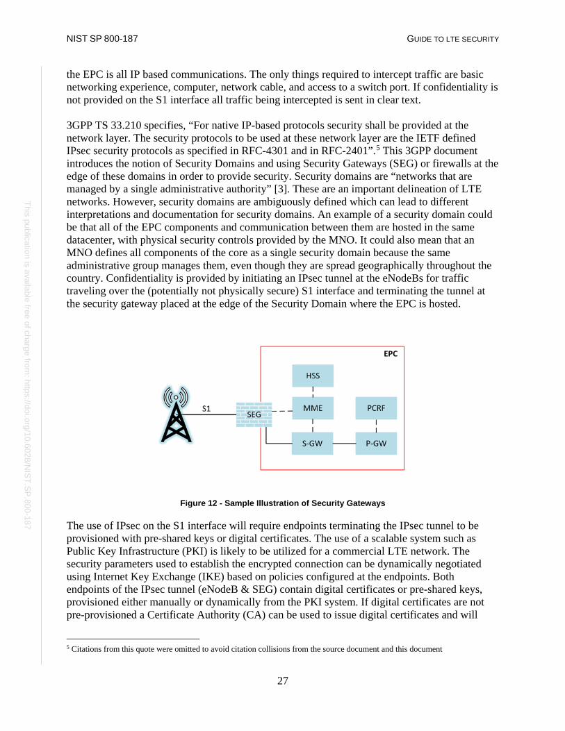
the EPC is all IP based communications. The only things required to intercept traffic are basic networking experience, computer, network cable, and access to a switch port. If confidentiality is not provided on the S1 interface all traffic being intercepted is sent in clear text. 3GPP TS 33.210 specifies, “For native IP-based protocols security shall be provided at the network layer. The security protocols to be used at these network layer are the IETF defined IPsec security protocols as specified in RFC-4301 and in RFC-2401”.5 This 3GPP document introduces the notion of Security Domains and using Security Gateways (SEG) or firewalls at the edge of these domains in order to provide security. Security domains are “networks that are managed by a single administrative authority” [3]. These are an important delineation of LTE networks. However, security domains are ambiguously defined which can lead to different interpretations and documentation for security domains. An example of a security domain could be that all of the EPC components and communication between them are hosted in the same datacenter, with physical security controls provided by the MNO. It could also mean that an MNO defines all components of the core as a single security domain because the same administrative group manages them, even though they are spread geographically throughout the country. Confidentiality is provided by initiating an IPsec tunnel at the eNodeBs for traffic traveling over the (potentially not physically secure) S1 interface and terminating the tunnel at the security gateway placed at the edge of the Security Domain where the EPC is hosted.
Figure 12 - Sample Illustration of Security Gateways
The use of IPsec on the S1 interface will require endpoints terminating the IPsec tunnel to be provisioned with pre-shared keys or digital certificates. The use of a scalable system such as Public Key Infrastructure (PKI) is likely to be utilized for a commercial LTE network. The security parameters used to establish the encrypted connection can be dynamically negotiated using Internet Key Exchange (IKE) based on policies configured at the endpoints. Both endpoints of the IPsec tunnel (eNodeB & SEG) contain digital certificates or pre-shared keys, provisioned either manually or dynamically from the PKI system. If digital certificates are not pre-provisioned a Certificate Authority (CA) can be used to issue digital certificates and will
5 Citations from this quote were omitted to avoid citation collisions from the source document and this document
NIST SP 800-187 GUIDE TO LTE SECURITY
28
This publication is available free of charge from: https://doi.org/10.6028/N
IST.SP.800-187
This publication is available free of charge from: https://doi.org/10.6028/N
IST.SP.800-187
need to be accessible to endpoints on the LTE network. For more information regarding Public Key Technology reference NIST SP 800-32 [26].
3.7 Core Network Security
As previously mentioned, 3GPP has specified optional security capabilities for various connections within LTE networks. However, even though 3GPP has noted in its standards that since LTE has introduced an all IP-based network, there needs to be more focus on security of the EPC than there was in 2G/3G since there is no specific security guidance tailored for the EPC [3]. Traditional IP network security guidelines and operational procedures may be beneficial. Since the core network handles the majority of control plane signaling, security needs to be a primary consideration. As specified in TS 33.210, the LTE network must be logically and physically divided into different security domains. If any components of the core are in different security domains then traffic between them is required to be routed through an SEG using IPsec for encryption and integrity protection [3]. Due to the ambiguities associated with defining a security domain, an operator’s core network may be considered one security domain. This implies a lack of security on standard communication between core LTE network components. If this is the case, then all of the signaling and user traffic being transmitted in the core would be transmitted in the clear, without confidentiality protection. However, if different pieces of the core are defined to exist in distinct security domains, then traffic must be encrypted using IPsec between them. To ensure that user and control data is protected in the appropriate places in the core network, careful consideration should be given to how security domains are defined for a network. Confidentiality protection may be implemented between different components of the core to ensure that the user and signaling traffic is protected. Currently, 3GPP is working on standards for Security Assurance Methodology (SECAM) for 3GPP nodes. The main document, TR 33.805, "studies methodologies for specifying network product security assurance and hardening requirements, with associated test cases when feasible, of 3GPP network products" [8]. There are plans to have accompanying documents to TR 33.805 that will have specific security considerations for each component of the core. 3GPP will first create the Security Assurance Specifications (SCAS) for the MME as a trial. Once the initial SCAS is completed for the MME, the 3GPP SA3 working group, the group that defines LTE security standards, will continue work on SCAS for the other network product classes. The MME SCAS, TR 33.806, is currently still in draft and addresses the security assurance specification for the MME. 3GPP is partnering with GSMA Network Equipment Security Assurance Group (NESAG) to establish an accreditation process and resolution process to evaluate products against the requirements defined in the SCAS. Core network security does not have any rigorous security specifications or requirements in the 3GPP standards. Future development of SCAS may require specific security controls to be implemented within the individual core components.

NIST SP 800-187 GUIDE TO LTE SECURITY
29
This publication is available free of charge from: https://doi.org/10.6028/N
IST.SP.800-187
This publication is available free of charge from: https://doi.org/10.6028/N
IST.SP.800-187
4 Threats to LTE Networks
This section explores general classes of threats to LTE networks grouped by related threat categories. It is of note that the 3GPP SA3 Working Group explored threats to LTE networks and authored a document listing many of threats addressed in this section [7]. Threat analyses external to 3GPP have been performed, such as [16], [17], and [18], and were used as input to this analysis. Many of the threats listed below have been identified via academic research, while others may be documented and reported real-world attacks that have occurred in deployed cellular systems. Organizations can use the higher-level threat categories presented in this section as a starting point for their own detailed threat models. While some of these threats may have an impact on network availability and resiliency, others are limited to user data integrity and confidentiality. Additionally, most of the threats mentioned here would only affect a limited portion of the network. With increased availability of low cost LTE hardware and software [21] many threats listed below can be implemented with a low level of complexity [19] [25].
4.1 General Cybersecurity Threats
LTE infrastructure components (e.g., eNodeB, MME, S-GW) may run atop of commodity hardware, firmware, and software, making it susceptible to publicly known software flaws pervasive in general purpose operating systems (e.g., FreeBSD and other *nix variants) or other software applications. Although heavy customization of systems may occur, commodity hardware and well-known operating systems that are utilized should be identified and understood. This implies that these systems need to be properly configured and regularly patched to remediate known vulnerabilities, such as those listed in the National Vulnerability Database [28]. The following subsections will address malware threats to specific network components and the management of an LTE network.
4.1.1 Malware Attacks on UE’s
Malicious code infecting a mobile device's operating system, other firmware, and installed applications could prevent a UE from accessing a cellular network. Malware could directly attack the baseband OS and its associated firmware. Attacking the baseband OS could change important configuration files for accessing the network or prevent important routines from running, such as those interpreting the signaling from a base station. Either of these would cause a denial of service.
4.1.2 Malware Attacks Impacting RAN Infrastructure
Malware installed on a mobile device, or infecting a mobile device's operating system and other firmware, could be part of a botnet launching an attack against a carrier’s radio network infrastructure. A Distributed Denial of Service (DDoS) attack could be launched via a continuous stream of attach requests, or requests for high bandwidth information and services. An unintentional DDoS attack on a carrier’s radio infrastructure has been seen to occur via a mobile application making a large number of update requests [11]. Malware can also compromise base station operating systems causing unexpected and undesirable equipment behavior.

NIST SP 800-187 GUIDE TO LTE SECURITY
30
This publication is available free of charge from: https://doi.org/10.6028/N
IST.SP.800-187
This publication is available free of charge from: https://doi.org/10.6028/N
IST.SP.800-187
4.1.3 Malware Attacks Impacting Core Infrastructure
Malware infecting components a carrier’s core network infrastructure would have the potential to log network activity, modify the configuration of critical communications gateways, and sniff user traffic (e.g., call traffic, SMS/MMS) depending on which components are infected. These types of attacks have been previously observed in GSM networks [22], but as of this time there is no known example of this attack within backend LTE infrastructure. A Distributed Denial of Service (DDoS) attack against an MME could be launched via a continuous stream of attach requests.
4.1.4 Unauthorized OAM Network Access
Operational and Access Management (OAM) networks are a vital part of an operational cellular network, providing remote access into geographically dispersed components of the network. These OAM network interfaces provide quick access to network components, allowing MNOs to manage and tune networks from one central location. Poor design, lax configuration management, and lack of hardening of these management networks and interfaces create a serious security risk to the network’s operational stability [7]. Unauthorized access to management interfaces can potentially allow malicious and unintentional misconfigurations of critical network systems.
4.2 Rogue Base Stations
Rogue base stations are unlicensed base stations that are not owned and operated by an authentic MNO. They broadcast a cellular network masquerading as a legitimate carrier network. The necessary hardware to construct these devices can be inexpensively obtained using commercial off-the-shelf (COTS) hardware. The software required to operate a 2G (GSM) base station is open source and freely available [20], and can be configured to operate as a rogue base station.
Figure 13 - Example Rogue Base Station
Rogue base stations exploit the fact that mobile handsets will attach to whichever base station is broadcasting as its preferred carrier network and is transmitting at the highest power level. Therefore, when a rogue base station is physically proximate to a mobile handset while transmitting at very high power levels, the handset may attempt to connect to the malicious network [23]. Mobile handsets are engineered to be backwards compatible with older cellular systems providing a consistent user experience during mobility. Rogue base stations take advantage of this backward compatibility and exploit weaknesses in these older cellular systems. At the time of this writing, a majority of rogue base stations broadcast a 2G GSM cellular network. The security protections offered by GSM lack mutual authentication between the
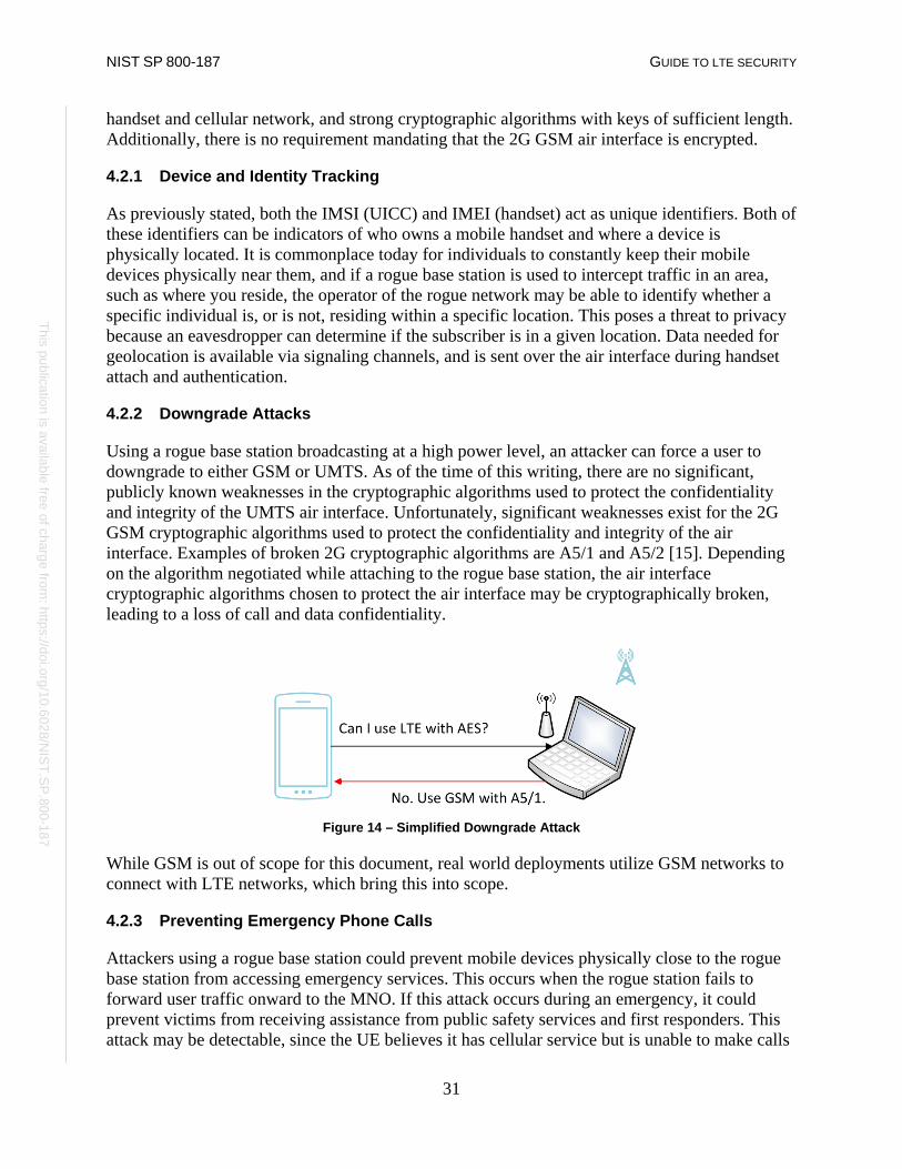
NIST SP 800-187 GUIDE TO LTE SECURITY
31
This publication is available free of charge from: https://doi.org/10.6028/N
IST.SP.800-187
This publication is available free of charge from: https://doi.org/10.6028/N
IST.SP.800-187
handset and cellular network, and strong cryptographic algorithms with keys of sufficient length. Additionally, there is no requirement mandating that the 2G GSM air interface is encrypted.
4.2.1 Device and Identity Tracking
As previously stated, both the IMSI (UICC) and IMEI (handset) act as unique identifiers. Both of these identifiers can be indicators of who owns a mobile handset and where a device is physically located. It is commonplace today for individuals to constantly keep their mobile devices physically near them, and if a rogue base station is used to intercept traffic in an area, such as where you reside, the operator of the rogue network may be able to identify whether a specific individual is, or is not, residing within a specific location. This poses a threat to privacy because an eavesdropper can determine if the subscriber is in a given location. Data needed for geolocation is available via signaling channels, and is sent over the air interface during handset attach and authentication.
4.2.2 Downgrade Attacks
Using a rogue base station broadcasting at a high power level, an attacker can force a user to downgrade to either GSM or UMTS. As of the time of this writing, there are no significant, publicly known weaknesses in the cryptographic algorithms used to protect the confidentiality and integrity of the UMTS air interface. Unfortunately, significant weaknesses exist for the 2G GSM cryptographic algorithms used to protect the confidentiality and integrity of the air interface. Examples of broken 2G cryptographic algorithms are A5/1 and A5/2 [15]. Depending on the algorithm negotiated while attaching to the rogue base station, the air interface cryptographic algorithms chosen to protect the air interface may be cryptographically broken, leading to a loss of call and data confidentiality.
Figure 14 – Simplified Downgrade Attack
While GSM is out of scope for this document, real world deployments utilize GSM networks to connect with LTE networks, which bring this into scope.
4.2.3 Preventing Emergency Phone Calls
Attackers using a rogue base station could prevent mobile devices physically close to the rogue base station from accessing emergency services. This occurs when the rogue station fails to forward user traffic onward to the MNO. If this attack occurs during an emergency, it could prevent victims from receiving assistance from public safety services and first responders. This attack may be detectable, since the UE believes it has cellular service but is unable to make calls

NIST SP 800-187 GUIDE TO LTE SECURITY
32
This publication is available free of charge from: https://doi.org/10.6028/N
IST.SP.800-187
This publication is available free of charge from: https://doi.org/10.6028/N
IST.SP.800-187
or send/receive data. This attack takes advantage of another vector that comes into play while making emergency phone calls when the preferred network is not available. When making an emergency phone call the UE might attach and attempt to send the call through a rogue base station, even if the base station is not masquerading as a legitimate network. There is a risk that the rogue base station will not forward the emergency call appropriately.
4.2.4 Unauthenticated REJECT Messages
As stated in section 3.4, during the UE attach procedure certain messages can be sent before security parameters are negotiated. One of these unauthenticated messages is the ATTACH REJECT message, which prevents a UE from completing the attach procedure. A rogue base station coercing a UE to participate in a UE attach procedure can send this unauthenticated ATTACH REJECT message. In response to receiving this message, a UE will no longer attempt to attach to this, or other LTE networks. Since the ATTACH REJECT message is sent even before the UE can authenticate the network, it is unable to distinguish the rogue base station from a real one. This can cause a Denial of Service (DoS) that may persist until a hard reboot of the UE is performed. Certain baseband implementations will not automatically try to reconnect if this ATTACH REJECT message is received [25]. Similarly, the TRACKING AREA UPDATE REJECT message can be sent by a rogue base station in the same manner, and may have the same effect as the ATTACH REJECT message.
4.3 Air Interface Eavesdropping
A complex eavesdropping attack is possible if the operator does not encrypt user plane LTE traffic on the Uu interface. Attackers would need to have the proper equipment to capture and store the radio communication between UE and eNodeB. In addition, the attackers would need software to identify the specific LTE frequencies and timeslots a UE is using to communicate so they can demodulate the captured traffic into IP packets.
4.4 Attacks Via Compromised Femtocell
Femtocells offer a user the ability to have a small base station located within their house or other area. These small base stations provide access to the core network where poor reception from an eNodeB would normally prevent consistent coverage. UEs attach to these devices like a typical eNodeB, but these devices often connect back to the MNO’s core via a user’s home internet connection through their Internet Service Provider (ISP). Femtocells have been standardized in LTE since release 8, and are referred to as Home eNodeBs, HeNodeBs, or HeNBs. HeNBs are mandated to have an IPsec connection back to an HeNB gateway (HeNB-GW) to protect traffic flowing into and out of a MNO’s core network [4]. If the HeNB is within the physical possession of an attacker, this provides unlimited time to identify a flaw on the HeNB. A compromised HeNB can be used in a manner similar to a rogue base station, but it also has access to the cryptographic keys used to protect the cellular connection. They will provide attackers access to clear text traffic before it is sent back to the core network. Common methods of attack exploit implementation flaws in the host OS and drivers [14].

NIST SP 800-187 GUIDE TO LTE SECURITY
33
This publication is available free of charge from: https://doi.org/10.6028/N
IST.SP.800-187
This publication is available free of charge from: https://doi.org/10.6028/N
IST.SP.800-187
4.5 Radio Jamming Attacks
Jamming attacks are a method of interrupting access to cellular networks by exploiting the radio frequency channel being used to transmit and receive information. Specifically, this attack occurs by decreasing the signal to noise ratio by transmitting static and/or noise at high power levels across a given frequency band. This classification of attack can be accomplished in a variety of ways requiring a varying level of skill and access to specialized equipment. Jamming that targets specific channels in the LTE spectrum and is timed specifically to avoid detection is often referred to as smart jamming. Broadcasting noise on a large swath of RF frequencies is referred to as dumb jamming.
4.5.1 Jamming UE Radio Interface
A low cost, high complexity attack has been proposed to prevent the transmission of UE signaling to an eNodeB. Research from Virginia Tech [12] and other institutions [13] suggests that, due to the relatively small amount of LTE control signaling used by the LTE air interface protocols, this attack is possible. Further research is required to ascertain the level of complexity, severity, and probability of this attack succeeding.
4.5.2 Jamming eNodeB Radio Interface
Base stations may have physical (e.g., fiber optic) or wireless (e.g., microwave) links to other base stations. These links are often used to perform call handoff operations. As mentioned in section 4.5.1, it may be possible to jam the wireless connections eNodeBs use to communicate with each other. Although theoretical, the same type of smart jamming attacks that are used against the UE could be modified to target communicating eNodeBs, which would prevent the transmission of eNodeB to eNodeB RF communication. The 3GPP SA3 Working Group states that this attack “…can be made with special hardware and countermeasures for these are not feasible to implement. However, jamming attacks may be detected and reported” [7]. This indicates that these types of jamming attacks are outside of this LTE threat model.
4.6 Backhaul and Core Eavesdropping
The backhaul connection handles data communication between the LTE core and eNodeBs (cell sites). In section 3.6 this document explores backhaul security and optional standards based features to provide confidentiality on this critical interface. If the LTE network is not utilizing confidentiality protection on the backhaul interface the communication being sent to and received from cell sites is vulnerable to eavesdropping. It would be trivial to intercept communication if a malicious actor had access to network equipment terminating the S1 interface.
4.7 Physical Attacks on Network Infrastructure
The cell site is the physical location containing all of the equipment necessary to run and operate an eNodeB. Although these sites sometimes are enclosed by a fence and protected by a physical security system, it is possible for these defenses to be circumvented. A denial of service attack is

NIST SP 800-187 GUIDE TO LTE SECURITY
34
This publication is available free of charge from: https://doi.org/10.6028/N
IST.SP.800-187
This publication is available free of charge from: https://doi.org/10.6028/N
IST.SP.800-187
possible if the equipment used to run the eNodeB is taken offline or somehow destroyed. For instance, copper theft is very common, and could result in a DoS. More subtle attacks that are much more difficult to detect are also possible if an attacker can obtain control of the systems running the eNodeB.
4.8 Attacks Against K
Cryptographic keys enable LTE to provide many of the strong security features built into the system. As discussed in section 3.1, there are many different keys used to protect different layers of LTE communication. All of these keys are derived from a secret pre-shared key referred to as ‘K’. This key resides in two places within the network: one is the USIM running on the UICC and the other is within the carrier’s HSS/AuC. The USIM manufacturer may also have access to K if it is responsible for burning the key into the USIM. Depending on how K is provisioned to the UICC it may be possible for a malicious actor to gain access to this secret key responsible for all of LTE’s cryptographic functions. If an actor gains access to K they have the potential to both impersonate a subscriber on the network and the ability to decrypt communication from the subscriber for whom K was provisioned.
4.9 Stealing Service
UICC cards are small cards that are removable from mobile devices by design. Service from an MNO is tied to a user’s UICC. This means it is possible for a UICC to be stolen from one mobile device, and placed into another with the goal of stealing service, including voice and data. Another means of stealing service is if an insider with access to the HSS or PCRF grants unapproved access to the network. For example, this could be an employee who activates UICCs unbeknownst to the MNO and sells them for personal profit.

NIST SP 800-187 GUIDE TO LTE SECURITY
35
This publication is available free of charge from: https://doi.org/10.6028/N
IST.SP.800-187
This publication is available free of charge from: https://doi.org/10.6028/N
IST.SP.800-187
5 Mitigations
This section identifies mitigations to the threats identified in the previous section. There is not a one to one mapping for the threats listed in Section 4 and the mitigations listed within Section 5, as there are unaddressed threats within this analysis, indicating open research areas. Each mitigation addresses at least one threat listed in Section 4. It is of note that the 3GPP SA3 working group has explored and authored a document detailing mitigations to many LTE threats listed in the previous section [7]. The higher-level mitigations listed in this section can be used by organizations looking to address threats identified during threat modeling exercises. Ensuring that many of the following mitigations are implemented in cellular networks is out of the realm of possibility for everyday users. The ability to enable change is largely in the hands of MNOs, mobile operating system developers, and hardware manufacturers. MNOs can work to implement many of the mitigation techniques described in this section; however challenges may exist where hardware, firmware, and software do not support these countermeasures. It is important to work with the ecosystem in order to research, develop, and implement these security features in commercial cellular equipment. If these mitigations are important to a user(s), they may need to request these security protections from the appropriate party. Many of the listed mitigations may simply be modifying certain configurations of already implemented features, something that would be feasible in the near term. Others would require software updates to mobile operating systems, and/or baseband processors, or modifications to 3GPP standards, which will take much more time to implement.
5.1 Cybersecurity Industry Recommended Practices
LTE infrastructure components (e.g., eNodeB, MME, S-GW) rely on purpose built systems to perform their network functions. The core software these systems run on is often a general purpose operating system. It is important that computer security recommended practices, including network, physical, and personnel security, be applied to these components in the same way they are applied to general information technology systems throughout industry today. Protection mechanisms such as patch management, configuration management (e.g., disabling serial ports on field network equipment), identity and access management, malware detection, and intrusion detection and prevention systems can be carefully planned and implemented throughout the MNO’s LTE infrastructure. These processes and protection mechanisms can be tailored to best support and protect the specialized LTE system. Addresses the following threats: 4.1, 4.1.2, 4.1.3, 4.1.4
5.2 Enabling Confidentiality on the Air Interface
Although integrity protection of NAS and RRC is mandatory, air interface encryption is left as an operator option in LTE systems [5]. Enabling cryptographic protection of the user plane over the Uu interface via the UPenc key can prevent passive eavesdropping attacks. It is possible that implementing confidentiality protection on the air interface can introduce significant latency into cellular networks, and it may also significantly impact a UE’s battery. Further testing, pilot programs, and capable hardware in conjunction with a phase approach can be followed to

NIST SP 800-187 GUIDE TO LTE SECURITY
36
This publication is available free of charge from: https://doi.org/10.6028/N
IST.SP.800-187
This publication is available free of charge from: https://doi.org/10.6028/N
IST.SP.800-187
provide confidentiality protection. Addresses the following threats: 4.3
5.3 Use of the Ciphering Indicator
As discussed in 4.2, the authentication procedure for the 2G GSM system does not perform mutual authentication between the mobile device and the base station. This allows for the possibility of a non-LTE rogue base station to perform a downgrade attack on a UE with an active LTE connection. This GSM connection may not be confidentiality protected. Current mobile devices do not provide the option for a user to know if their UE’s connection is encrypted to the eNodeB. 3GPP provides a mechanism to alert a user to an unencrypted connection, referred to as the ciphering indicator. The ciphering indicator is defined in 3GPP TS 22.101, which defines this indicator as a feature to inform the user as to the status of the user plane confidentiality protection. This feature could be implemented as a user interface notification appearing on the user’s mobile device. It is possible for the MNO to disable this feature with a setting in the USIM. 3GPP specifies the default behavior of the UE shall be to obey the setting configured in the USIM. However, it is possible for the UE to provide a user interface option to ignore the USIM setting and provide the user an indication of the status of the user plane confidentiality protection. “Ciphering itself is unaffected by this feature, and the user can choose how to proceed” [6]. This indicator would be beneficial to informed users wishing to know if their over-the-air cellular connection is encrypted or not. This may require new software from either the mobile operating system vendor (e.g., Apple, Google, Microsoft) or the baseband manufacturer (e.g., Qualcomm, Intel, Samsung). Addresses the following threats: 4.3
5.4 User-Defined Option for Connecting to LTE Networks
Rogue base stations often exploit the lack of mutual authentication that exists in GSM. Current mobile devices do not provide average users the option to ensure that a user's mobile device only connects to a 4G LTE network, a specific MNO’s (or MVNO’s) network, or a specific physical cellular site. If users could ensure that their mobile device is connected only to a 4G LTE network, mutual authentication is achieved between their UE and eNodeB via the LTE AKA protocol, and an active rogue base station attack downgrading the connection to GSM should not be possible. It is of note that a preferred network technology listing exists on many UEs, and depending on the platform, similar options may exist in testing modes. It is unclear if this option would prevent a UE that is under attack from connecting to a rogue base station. The current functionality is not intended to be a security feature but could provide vital defense against rogue base stations. The user-defined option is not widely deployed in UEs, and would likely require software updates from the mobile operating system vendor (e.g., Apple, Google, Microsoft) and/or the baseband manufacturer (e.g., Qualcomm, Intel, Samsung). This option would be beneficial to informed users wishing to only connect to LTE networks. Addresses the following threats: 4.2.1, 4.2.2. 4.2.3

NIST SP 800-187 GUIDE TO LTE SECURITY
37
This publication is available free of charge from: https://doi.org/10.6028/N
IST.SP.800-187
This publication is available free of charge from: https://doi.org/10.6028/N
IST.SP.800-187
5.5 Ensure Confidentiality Protection of S1 Interface
Both physical and logical security can be used to secure the backhaul connection of an LTE network. Placing devices in physically secure locations is an important step in securing the backhaul connection and protecting it from malicious actors. Cryptographically securing the IP traffic traversing the backhaul connection is seen as equally important and provides a higher level of assurance, and is possible using NDS/IP. Implementing confidentiality protection on the S1 interface may introduce latency into cellular backhaul connections, and further research is required to understand if this latency would noticeably degrade service and traffic throughput. Addresses the following threats: 4.6
5.6 Encrypt Exposed Interfaces Between Core Network Components
To the extent that it does not significantly affect availability of network resources, the interfaces between core network nodes can be confidentiality protected in some way, possibly via the mechanisms defined in 3GPP TS 33.210. 3GPP and ETSI will provide forthcoming guidance for protecting these interfaces. Addresses the following threats: 4.6
5.7 Use of SIM/USIM PIN Code
As previously noted, some modern mobile equipment operating systems implement the USIM PIN specified by 3GPP TS 121.111 [31]. This enables local user authentication to the USIM via PIN configured on a UICC. Enabling the UICC PIN can prevent unauthorized network access should the UICC be stolen or lost. An individual stealing the UICC and placing it into another device would be required to enter a PIN before they could continue any further. Many UICCs lock after 10 incorrect attempts and the user’s MNO would be required to provide an unlocking code to make the USIM usable again. The SIM/USIM PIN may degrade the user experience by adding additional authentication and slowing down the UE boot process. Addresses the following threats: 4.9
5.8 Use of Temporary Identities
A subscriber’s permanent identity, the IMSI, is one of the first parameters sent to an eNodeB when a UE attaches to the LTE network. IMSIs are sometimes sent in clear text over the air interface, and this may be unavoidable in certain scenarios. 3GPP defines multiple temporary identities that MNOs can leverage to avoid sending these sensitive identifiers over the air interface, such as the GUTI in LTE. When the GUTI is in use, user tracking should become more difficult. GUTIs need to be implemented in a manner so they are periodically refreshed via the NAS GUTI Reallocation Command to ensure that it is a truly temporary identifier [19]. Addresses the following threats: 4.2.1
5.9 3rd Party Over-the-Top Solutions
If an MNO is not encrypting a user’s traffic, or if a passive eavesdropping attack occurs, using a 3rd party over-the-top service can provide strong authentication, integrity and confidentiality protection for user data. This mitigation would effectively use an MNO’s network as a “dumb pipe,” and a user would use an application running on the general-purpose mobile operating

NIST SP 800-187 GUIDE TO LTE SECURITY
38
This publication is available free of charge from: https://doi.org/10.6028/N
IST.SP.800-187
This publication is available free of charge from: https://doi.org/10.6028/N
IST.SP.800-187
system to provide video, audio, or some other communication service. Additionally, 3rd party over-the-top solutions can act as a defense in depth measure, choosing not to rely solely on their MNO to provide confidentiality protection. Addresses the following threats: 4.2.2, 4.3, 4.4, 4.6, 4.8
5.10 Unauthenticated Reject Message Behavior
In the presence of illegitimate messages with the ability to deny network access, a possible mitigation is for the UE to continue to search for other available networks while ignoring the network denying service. The baseband firmware could be tested to understand the behavior these systems exhibit when in the presence of unauthenticated reject messages. Additional research and development is needed to ensure that baseband processors are exhibiting behavior that does not cause unintentional DoS when receiving an illegitimate reject message. Addresses the following threats: 4.2.4
5.11 Physical Security of Cell Site Equipment
Physical security of cellular equipment is important to prevent intentional and unintentional incidents affecting availability. 3GPP TS 33.401 standard mentions “physically protected” systems and interfaces, underscoring the need for such protections, but does not go on to describe what actual physical security controls should be put in place. However, the Physical and Environmental Protection control family from NIST SP 800-53 is a reasonable list of controls to use as a starting point [33]. The National Public Safety Telecommunications Council (NPSTC) also describes physical access controls that are useful for securing cellular sites in the context of public safety [34]. For instance, the document suggests that fences and gates should be locked, and that detection methods such as video surveillance should be implemented. Addresses the following threats: 4.7
5.12 Rogue Base Station Detection
As previously stated, rogue base stations can compromise the security of cellular devices and associated equipment. It is possible to detect the presence of these rogue base stations, although some may consider this technology still in developmental stages. Mobile applications can be used to detect the presence of rogue base stations, although using specific chipsets on older device models are often required [35]. Different approaches can be used for detection purposes. One method is to receive the information contained within broadcast messages originating from base stations, and checking that information against known-good values. Another method is to store lists of known base stations, and alert users when new base stations are identified. In this situation, it is up to the user to make the final determination. Turnkey solutions are also available for purchase that will detect the presence of rogue base stations. Either technology has limitations and may provide false positives, but this is an active area of research that may assist organizations concerned about the presence of rogue base stations. Addresses the following threats: 4.2.1, 4.2.2, 4.2.3, 4.2.4

NIST SP 800-187 GUIDE TO LTE SECURITY
39
This publication is available free of charge from: https://doi.org/10.6028/N
IST.SP.800-187
This publication is available free of charge from: https://doi.org/10.6028/N
IST.SP.800-187
6 Conclusions
When compared to previous cellular networks, the security capabilities provided by LTE are markedly more robust. The additions of mutual authentication between the cellular network and the UE, alongside the use of publicly reviewed cryptographic algorithms with sufficiently large key sizes are positive steps forward in improving the security of cellular networks. The enhanced key separation introduced into the LTE cryptographic key hierarchy and the mandatory integrity protection also help to raise the bar. Yet LTE systems are rarely deployed in a standalone fashion - they coexist with previous cellular infrastructure already in place. Older cellular systems continue to be utilized throughout many different industries today, satisfying a variety of use cases. With this in mind, it’s easy to see why LTE networks are often deployed in tandem with GSM and UMTS networks. This multi-generational deployment of cellular networks may lead to an overall decrease in cellular security. A primary example of this is the requirement for the baseband firmware to remain backward compatible, supporting legacy security configurations. The interconnection of these technologies introduces additional complexity into an already complicated system that is distributed over an immense geographic area, that is continental in scale. Cellular networks traditionally use separate networks to communicate call signaling information. Specifically, the SS7 network has been in use for decades and has its own unique set of security challenges that is separate from the cellular network technology. An LTE-specific version of Diameter was specified by 3GPP to, in part, resolve the challenges associated with the use of SS7, although it is not widely deployed. The Federal Communications Commission’s (FCC) Communications Security, Reliability and Interoperability Council (CSRIC) Working Group 10 issued a report on SS7 security issues, but more work is needed before these threats are fully resolved [32]. It’s important for MNOs and all interested parties to perform their own security analysis of this technology in order to understand how to appropriately mitigate the risks introduced by these signaling technologies. This security analysis should include how any partnering MNO also mitigates these risks in their own network, since a weakness in one MNO’s network adversely affects the security of those its connected to. LTE’s sole use of IP technology is a major differentiator from previous cellular networks. LTE does not use circuit switching, instead opting to move to a purely packet switched system. IP is a commoditized technology that is already understood by Information Technology practitioners, which presents both challenges and opportunities. Attackers may be able to leverage existing tools for exploiting IP-based networks to attack the LTE core and other associated cellular infrastructure within an MNO’s network. Conversely, this may allow already existing IP-based defensive technology to be immediately applied to LTE networks. Hopefully, the application of these technologies will offer novel ways to increase system security. The following list highlights areas of the LTE security architecture that either lack the appropriate controls or have unaddressed threats:
• Default Confidentiality Protection for User Traffic: The LTE standards do not provide confidentiality protection for user traffic as the default system configuration. Enabling
NIST SP 800-187 GUIDE TO LTE SECURITY
40
This publication is available free of charge from: https://doi.org/10.6028/N
IST.SP.800-187
This publication is available free of charge from: https://doi.org/10.6028/N
IST.SP.800-187
user traffic encryption by default, except for certain scenarios such as emergency calls, would provide out of the box security to end users.
• Prohibiting user traffic integrity: Although the LTE standards require integrity protection for critical signaling traffic, integrity protection for user traffic is explicitly prohibited, as stated in section 3.4.
• Lack of protection against jamming attacks: This is an active area of research, and mitigations have been proposed, although it is unclear if these mitigations have been appropriately vetted and considered for inclusion into the LTE standard.
• OAM Networks: Vulnerabilities potentially exist on the OAM network depending on how it is architected and managed.
While this document is focused on the fundamentals of LTE and its security architecture, many concepts were considered out of the scope of our analysis. Some of these concepts are services that build on top of the LTE architecture, while others come from specific implementations and uses of an LTE network. It is important that the security implications introduced by these concepts listed below are well understood, and require further research:
• Security analysis of IMS, • Security analysis of VoLTE, • Protection against jamming attacks, • Enabling UE network interrogation, • LTE for public safety use, • Security implications of Over the Air (OTA) updates, • Multi-Operator Core Networks (MOCN), and • Security capabilities of Network Function Virtualization (NFV).
This document identified threats to LTE networks, and described potential mitigations to these issues. Exploring and enabling the mitigations included within this document will be a coordinated effort between mobile OS vendors, baseband firmware developers, standards organizations, mobile network operators, and end users. Developing solutions to the problems identified here, and continuing to perform relevant research is an important task since LTE is the nation’s dominant cellular communications technology.

NIST SP 800-187 GUIDE TO LTE SECURITY
41
This publication is available free of charge from: https://doi.org/10.6028/N
IST.SP.800-187
This publication is available free of charge from: https://doi.org/10.6028/N
IST.SP.800-187
Appendix A—Acronyms and Acronyms
Selected acronyms and abbreviations used in this paper are defined below.
2G 2nd Generation 3G 3rd Generation 4G 4th Generation AES Advanced Encryption Standard AKA Authentication and Key Agreement APN Access Point Name AS Access Strum AuC Authentication Center AUTN Authentication Token CA Certificate Authority CK Confidentiality Key COTS Commercial off-the-Shelf COW Cell on Wheels CSFB Circuit Switch Fallback CSRIC Communications Security, Reliability and Interoperability Council DDoS Distributed Denial of Service DeNB Donor eNodeB DMZ Demilitarized Zone DoS Denial of Service DRB Data Radio Bearer EDGE Enhanced Data rates for GSM Evolution EEA EPS Encryption Algorithm EIA EPS Integrity Algorithm EIR Equipment Identity Register E-RAB E-UTRAN Radio Access Bearer eNB eNodeB, Evolved Node B eNodeB Evolved Node B EPC Evolved Packet Core EPS Evolved Packet System E-UTRAN Evolved Universal Terrestrial Radio Access Network FCC Federal Communications Commission GPRS General Packet Radio Service GSM Global System for Mobile Communications GSMA GSM Association GUTI Globally Unique Temporary Identity HeNB Home eNodeB HeNB-GW HeNB Gateway HSPA High Speed Packet Access HSS Home Subscriber Server IK Integrity Key IKE Internet Key Exchange
NIST SP 800-187 GUIDE TO LTE SECURITY
42
This publication is available free of charge from: https://doi.org/10.6028/N
IST.SP.800-187
This publication is available free of charge from: https://doi.org/10.6028/N
IST.SP.800-187
IMEI International Mobile Equipment Identifier IMS IP Multimedia Subsystem IMSI International Mobile Subscriber Identity IoT Internet of Things IP Internet Protocol ISP Internet Service Provider LTE Long Term Evolution MAC Medium Access Control ME Mobile Equipment MitM Man in the middle MME Mobility Management Entity MMS Multimedia Messaging Service MNO Mobile Network Operator MPLS Multiprotocol Label Switching MVNO Mobile Virtual Network Operator NAS Non-Access Stratum NDS/IP Network Domain Security / Internet Protocol NESAG Network Equipment Security Assurance Group NFC Near Field Communications NFV Network Function Virtualization NH Next Hop OAM Operational and Access Management OS Operating System OTA Over the Air PCRF Policy and Charging Rules Function PDCP Packet Data Convergence Protocol PDN Packet Data Network P-GW Packet Gateway PHY Physical Access PKI Public Key Infrastructure PSTN Public Switched Telephone Network QoS Quality of Service RAND Random Parameter RAN Radio Access Network RF Radio Frequency RES Response RN Relay Node RRC Radio Resource Control SCAS Security Assurance Specifications SECAM Security Assurance Methodology SEG Security Gateway S-GW Serving Gateway SIM Subscriber Identity Module SMC Security Mode Command SMS Short Message Service SQN Sequence Number

NIST SP 800-187 GUIDE TO LTE SECURITY
43
This publication is available free of charge from: https://doi.org/10.6028/N
IST.SP.800-187
This publication is available free of charge from: https://doi.org/10.6028/N
IST.SP.800-187
SRB Signaling Radio Bearer SoC System on a Chip SQN Sequence Number TCP Transmission Control Protocol TMSI Temporary Mobile Subscriber Identity TR Technical Report TS Technical Specification UE User Equipment UEA UMTS Encryption Algorithm UIA UMTS Integrity Algorithm UICC Universal Integrated Circuit Card UMTS Universal Mobile Telecommunications System USIM Universal Subscriber Identity Module Uu LTE air interface VoLTE Voice over LTE VoIP Voice over IP VPN Virtual Private Network WiMAX Worldwide Interoperability for Microwave Access XRES Expected result

NIST SP 800-187 GUIDE TO LTE SECURITY
44
This publication is available free of charge from: https://doi.org/10.6028/N
IST.SP.800-187
This publication is available free of charge from: https://doi.org/10.6028/N
IST.SP.800-187
Appendix B—References
[1] 3rd Generation Partnership Project, Releases, http://www.3gpp.org/specifications/67-releases [accessed 12/13/17].
[2] 3rd Generation Partnership Project, General Packet Radio Service (GPRS) enhancements for Evolved Universal Terrestrial Radio Access Network (E-UTRAN) access, 3GPP TS 23.401 V13.4, 2015. http://www.3gpp.org/DynaReport/23401.htm [accessed 12/13/17].
[3] 3rd Generation Partnership Project, Network Domain Security (NDS); IP network layer security, 3GPP TS 33.210 V12.2.0, 2012. http://www.3gpp.org/DynaReport/33210.htm [accessed 12/13/17].
[4] 3rd Generation Partnership Project, Security of Home Node B (HNB), 3GPP TS 33.320 V12.1, 2014. http://www.3gpp.org/DynaReport/33320.htm [accessed 12/13/17].
[5] 3rd Generation Partnership Project, System Architecture Evolution (SAE): Security Architecture, 3GPP TS 33.401 V12.12, 2014. http://www.3gpp.org/DynaReport/33401.htm [accessed 12/13/17].
[6] 3rd Generation Partnership Project, Service aspects; Service Principles, 3GPP TS 22.101 V14.1, 2015. http://www.3gpp.org/DynaReport/22101.htm [accessed 12/13/17].
[7] 3rd Generation Partnership Project, Rationale and track of security decisions in Long Term Evolution (LTE) RAN / 3GPP System Architecture Evolution (SAE), 3GPP TR 33.821 V9, 2009. http://www.3gpp.org/DynaReport/33821.htm [accessed 12/13/17].
[8] 3rd Generation Partnership Project, Study on security assurance methodology for 3GPP network products, 3GPP TR 33.805 V12, 2013. http://www.3gpp.org/DynaReport/33805.htm [accessed 12/13/17].
[9] 3rd Generation Partnership Project, Service requirements for the Evolved Packet System (EPS), 3GPP TS 22.278 V13.2, 2014. http://www.3gpp.org/DynaReport/22278.htm [accessed 12/13/17].
[10] 3rd Generation Partnership Project, Non-Access-Stratum (NAS) protocol for Evolved Packet System (EPS), 3GPP TS 24.301 V13.4, 2015. http://www.3gpp.org/dynareport/24301.htm [accessed 12/13/17].
[11] M. Dano, “The Android IM App That Brought T-Mobile's Network to Its Knees.” Fierce Wireless, October 14, 2010.

NIST SP 800-187 GUIDE TO LTE SECURITY
45
This publication is available free of charge from: https://doi.org/10.6028/N
IST.SP.800-187
This publication is available free of charge from: https://doi.org/10.6028/N
IST.SP.800-187
https://www.fiercewireless.com/wireless/android-im-app-brought-t-mobile-s-network-to-its-knees [accessed 12/13/17].
[12] J. Reed, Comments of Wireless @ Virginia Tech, Virginia Tech College of Engineering, November 8, 2012. http://www.ntia.doc.gov/files/ntia/va_tech_response.pdf [accessed 12/13/17].
[13] R. Bassil, A. Chehab, I. Elhajj, and A. Kayssi, “Signaling oriented denial of service on lte networks,” in Proceedings of the 10th ACM international symposium on Mobility management and wireless access. ACM, 2012, pp. 153-158. https://doi.org/10.1145/2386995.2387024.
[14] D. DePerry, T. Ritter, and A. Rahimis, Traffic Interception & Remote Mobile Phone Cloning with a Compromised CDMA Femtocell, Defcon 2013, Las Vegas, Nevada, August 1-4, 2013. https://www.defcon.org/images/defcon-21/dc-21-presentations/DePerry-Ritter/DEFCON-21-DePerry-Ritter-Femtocell-Updated.pdf [accessed 12/13/17].
[15] D. Forsberg, G. Horn, W.-D. Moeller, and V. Niemi, LTE Security, 2nd ed. Wiley, December 2012. 366 pp.
[16] A. Prasad and S. Aissi, Mobile Devices Security: Evolving Threat Profile of Mobile Networks, RSA 2014. http://www.rsaconference.com/writable/presentations/file_upload/mbs-t07-mobile-devices-security-evolving-threat-profile.pdf [accessed 12/13/17].
[17] D. Bhasker, “4G LTE Security for Mobile Network Operators,” Journal of Cyber Security and Information Systems 1(4) October 2013, pp. 20-29. https://www.csiac.org/journal-article/4g-lte-security-for-mobile-network-operators/ [accessed 12/13/17].
[18] A.N. Bikos and N. Sklavos, “LTE/SAE Security Issues on 4G Wireless Networks,” IEEE Security & Privacy 11(2) March/April 2013, pp. 55-62. https://doi.org/10.1109/MSP.2012.136.
[19] A. Shaik, R. Borgaonkar, N. Asokan, V. Niemi, and J.-P. Seifert, Practical attacks against privacy and availability in 4G/LTE mobile communication systems, arXiv.org, Report 1510.07563v3, October 26, 2015 (revised August 7, 2017), 16 pp. https://arxiv.org/abs/1510.07563 [accessed 12/13/17].
[20] Range Networks, OpenBTS Project [Web site]. http://openbts.org [accessed 12/13/17].
[21] B. Wojtowicz, OpenLTE - An open source 3GPP LTE implementation, July 30, 2017. https://sourceforge.net/projects/openlte/ [accessed 12/13/17].

NIST SP 800-187 GUIDE TO LTE SECURITY
46
This publication is available free of charge from: https://doi.org/10.6028/N
IST.SP.800-187
This publication is available free of charge from: https://doi.org/10.6028/N
IST.SP.800-187
[22] Kaspersky Labs, The Regin Platform: Nation-State Ownage of GSM
Networks, Version 1.0, November 24, 2014. http://securelist.com/files/2014/11/Kaspersky_Lab_whitepaper_Regin_platform_eng.pdf [accessed 12/13/17].
[23] K. Paget, Practical Cellphone Spying [presentation], Defcon 18, July 10, 2010. http://www.tombom.co.uk/blog/?p=262 [accessed 12/13/17].
[24] D. Hulton, Intercepting GSM traffic [presentation], Blackhat DC 2008, March 2008. https://www.blackhat.com/presentations/bh-dc-08/Steve-DHulton/Presentation/bh-dc-08-steve-dhulton.pdf [accessed 12/13/17].
[25] R. Piqueras Jover, LTE security and protocol exploits [presentation], ShmooCon 2016. http://www.ee.columbia.edu/~roger/ShmooCon_talk_final_01162016.pdf [accessed 12/13/17].
[26] NIST Special Publication (SP) 800-32, Introduction to Public Key Technology and Federal PKI Infrastructure, National Institute of Standards and Technology, February 2001. https://doi.org/10.6028/NIST.SP.800-32.
[27] ETSI/SAGE, Specification of the 3GPP Confidentiality and Integrity Algorithms UEA2 & UIA2. Document 1: UEA2 and UIA2 Specification, Version 2.1, March 16, 2009. https://www.gsma.com/aboutus/wp-content/uploads/2014/12/uea2uia2d1v21.pdf [accessed 12/13/17].
[28] NIST, National Vulnerability Database [Web site], https://nvd.nist.gov/ [accessed 12/13/17].
[29] 3rd Generation Partnership Project, Evolved Universal Terrestrial Radio Access Network (E-UTRAN); S1 data transport, 3GPP TS 36.414 V12.1, 2014. http://www.3gpp.org/dynareport/36414.htm [accessed 12/13/17].
[30] 3rd Generation Partnership Project, Evolved Universal Terrestrial Radio Access (E-UTRA); Radio Resource Control (RRC); Protocol specification, 3GPP TS 36.331 V12.8, 2016. http://www.3gpp.org/dynareport/36331.htm [accessed 12/13/17].
[31] 3rd Generation Partnership Project, USIM and IC card requirements, 3GPP TS 21.111 V13, 2016. http://www.3gpp.org/DynaReport/21111.htm [accessed 12/13/17].
[32] Communications Security, Reliability and Interoperability Council (CSRIC), Working Group 10, Legacy Systems Risk Reductions: Final Report, March
NIST SP 800-187 GUIDE TO LTE SECURITY
47
This publication is available free of charge from: https://doi.org/10.6028/N
IST.SP.800-187
This publication is available free of charge from: https://doi.org/10.6028/N
IST.SP.800-187
2017. https://www.fcc.gov/files/csric5-wg10-finalreport031517pdf [accessed 12/13/17].
[33] NIST Special Publication (SP) 800-53 Revision 4, Security and Privacy Controls for Federal Information Systems and Organizations, National Institute of Standards and Technology, April 2013 (including updates as of January 22, 2015). https://doi.org/10.6028/NIST.SP.800-53r4.
[34] National Public Safety Telecommunications Council, Defining Public Safety Grade Systems and Facilities: Final Report, May 22, 2014. http://www.npstc.org/download.jsp?tableId=37&column=217&id=3066&file=Public_Safety_Grade_Report_140522.pdf [accessed 12/13/17].
[35] S. Park, A. Shaik, R. Borgaonkar, A. Martin, and J.-P. Seifert, White-Stingray: Evaluating IMSI Catchers Detection Applications, 11th Usenix Workshop on Offensive Technologies (WOOT ’17), August 2017. https://www.usenix.org/system/files/conference/woot17/woot17-paper-park.pdf [accessed 12/13/17].