Jeep Cherokee XJ 1995-1999 Transmission and Transfer Case
344
TRANSMISSION AND TRANSFER CASE CONTENTS page page 30RH/32RH AUTOMATIC TRANSMISSION .... 67 AW 4 AUTOMATIC TRANSMISSION ........ 165 AX 15 MANUAL TRANSMISSION ........... 33 AX 4/5 MANUAL TRANSMISSION ............ 1 NP231 TRANSFER CASE ................. 283 NP242 TRANSFER CASE ................. 306 TRANSMISSION/TRANSFER CASE SPECIFICATIONS ..................... 333 AX 4/5 MANUAL TRANSMISSION INDEX page page Cleaning and Inspection .................... 13 Gear Ratios .............................. 2 General Information ........................ 1 Recommended Lubricant .................... 2 Service Diagnosis .......................... 2 Shift Pattern .............................. 2 Transmission Assembly and Adjustment ......... 16 Transmission Disassembly and Overhaul ......... 5 Transmission Identification ................... 2 Transmission Installation ..................... 5 Transmission Removal ...................... 3 GENERAL INFORMATION The AX 4 is a four speed manual transmission. The AX 5 is a five speed manual transmission. Fifth gear in the AX 5 is an overdrive range. The shift mecha- nism in both models is integral and mounted in the shift tower portion of the adapter housing (Fig. 1). The AX 4/5 is used for 2.5L engine applications. Fig. 1 AX 4/5 Manual Transmission J TRANSMISSION AND TRANSFER CASE 21 - 1
description
Manual service Jeep Cherokee XJ
Transcript of Jeep Cherokee XJ 1995-1999 Transmission and Transfer Case

TRANSMISSION AND TRANSFER CASE
CONTENTS
page page
30RH/32RH AUTOMATIC TRANSMISSION . . . . 67AW 4 AUTOMATIC TRANSMISSION . . . . . . . . 165AX 15 MANUAL TRANSMISSION . . . . . . . . . . . 33AX 4/5 MANUAL TRANSMISSION . . . . . . . . . . . . 1
NP231 TRANSFER CASE . . . . . . . . . . . . . . . . . 283NP242 TRANSFER CASE . . . . . . . . . . . . . . . . . 306TRANSMISSION/TRANSFER CASE
SPECIFICATIONS . . . . . . . . . . . . . . . . . . . . . 333
AX 4/5 MANUAL TRANSMISSION
INDEX
page page
Cleaning and Inspection . . . . . . . . . . . . . . . . . . . . 13Gear Ratios . . . . . . . . . . . . . . . . . . . . . . . . . . . . . . 2General Information . . . . . . . . . . . . . . . . . . . . . . . . 1Recommended Lubricant . . . . . . . . . . . . . . . . . . . . 2Service Diagnosis . . . . . . . . . . . . . . . . . . . . . . . . . . 2Shift Pattern . . . . . . . . . . . . . . . . . . . . . . . . . . . . . . 2
Transmission Assembly and Adjustment . . . . . . . . . 16Transmission Disassembly and Overhaul . . . . . . . . . 5Transmission Identification . . . . . . . . . . . . . . . . . . . 2Transmission Installation . . . . . . . . . . . . . . . . . . . . . 5Transmission Removal . . . . . . . . . . . . . . . . . . . . . . 3
GENERAL INFORMATIONThe AX 4 is a four speed manual transmission. The
AX 5 is a five speed manual transmission. Fifth gearin the AX 5 is an overdrive range. The shift mecha-nism in both models is integral and mounted in the
shift tower portion of the adapter housing (Fig. 1).The AX 4/5 is used for 2.5L engine applications.
Fig. 1 AX 4/5 Manual Transmission
J TRANSMISSION AND TRANSFER CASE 21 - 1

TRANSMISSION IDENTIFICATIONThe AX 4/5 identification code is on the bottom sur-
face of the transmission case near the fill plug (Fig. 2).The first number is year of manufacture. The secondand third numbers indicate month of manufacture. Thenext series of numbers is the transmission serial num-ber.
GEAR RATIOSGear ratios for the AX 4 and AX 5 are as follows:
• First gear: 3.93:1• Second gear: 2.33:1• Third gear: 1.45:1• Fourth gear: 1.00:1• Fifth gear (AX 5): 0.85:1• Reverse gear: 4.74:1
SHIFT PATTERNThe AX 4/5 first through fourth gear shift pattern
is in a conventional H configuration. On the AX 5,fifth gear is up and to the right and reverse gear isdown and to the right (Fig. 3).
RECOMMENDED LUBRICANTRecommended lubricant for AX 4/5 transmissions is
Mopar 75W-90, API Grade GL-5 gear lubricant, orequivalent.
Correct lubricant level is from the bottom edge, tono more than 6 mm (1/4 in.) below the bottom edge ofthe fill plug hole.
The fill plug is at the passenger side of the adapterhousing Fig. 4). The drain plug is at the bottom ofthe case.
Approximate dry fill lubricant capacity is 3.3 liters(3.5 qts.).
SERVICE DIAGNOSIS
LOW LUBRICANT LEVELA low transmission lubricant level is generally the
result of a leak, inadequate lubricant fill, or an incor-rect lubricant level check.
Leaks can occur at the mating surfaces of the gearcase, intermediate plate and adaptor or extensionhousing, or from the front/rear seals. A suspectedleak could also be the result of an overfill condition.
Leaks at the rear of the extension or adapter hous-ing will be from the housing oil seals. Leaks at com-ponent mating surfaces will probably be the result ofinadequate sealer, gaps in the sealer, incorrect bolttightening, or use of a non-recommended sealer.
A leak at the front of the transmission will be fromeither the front bearing retainer or retainer seal. Lu-bricant may be seen dripping from the clutch housingafter extended operation. If the leak is severe, it mayalso contaminate the clutch disc causing slip, graband chatter.
Transmissions filled from air or electrically poweredlubricant containers can be underfilled. This generally
Fig. 2 Transmission Identification
Fig. 3 AX 4/5 Shift Pattern
Fig. 4 Fill Plug Location
21 - 2 AX 4/5 MANUAL TRANSMISSION J

happens when the container delivery mechanism is im-properly calibrated. Always check the lubricant level af-ter filling to avoid an under fill condition.
A correct lubricant level check can only be madewhen the vehicle is level; use a drive-on hoist to en-sure this. Also allow the lubricant to settle for aminute or so before checking. These recommenda-tions will ensure an accurate check and avoid an un-der-or-overfill condition.
HARD SHIFTINGHard shifting is usually caused by a low lubricant
level, improper or contaminated lubricants, compo-nent damage, incorrect clutch adjustment, or by adamaged clutch pressure plate or disc.
Substantial lubricant leaks can result in gear, shiftrail, synchro and bearing damage. If a leak goes un-detected for an extended period, the first indicationsof a problem are usually hard shifting and noise.
Incorrect or contaminated lubricants can also con-tribute to hard shifting. The consequence of usingnon-recommended lubricants is noise, excessive wear,internal bind and hard shifting.
Improper clutch release is a frequent cause of hardshifting. Incorrect adjustment or a worn, damagedpressure plate or disc can cause incorrect release. Ifthe clutch problem is advanced, gear clash duringshifts can result.
Worn or damaged synchro rings can cause gear clashwhen shifting into any forward gear. In some new or re-built transmissions, new synchro rings may tend tostick slightly causing hard or noisy shifts. In mostcases, this condition will decline as the rings wear-in.
TRANSMISSION NOISEMost manual transmissions make some noise dur-
ing normal operation. Rotating gears generate a mildwhine that is audible but only at extreme speeds.
Severe, highly audible transmission noise is gener-ally the result of a lubricant problem. Insufficient,improper, or contaminated lubricant will promoterapid wear of gears, synchros, shift rails, forks andbearings. The overheating caused by a lubricantproblem, can also lead to gear breakage.
TRANSMISSION REMOVAL(1) Shift transmission into first or third gear. Then
raise vehicle on hoist.(2) Support engine with adjustable jack stand. Po-
sition wood block between jack and oil pan to avoiddamaging pan.
(3) Disconnect necessary exhaust system components.(4) Remove skid plate.(5) Disconnect rear cushion and bracket from
transmission (Fig. 5).(6) Remove rear crossmember.
Fig. 5 Rear Mount Components (YJ Shown)
J AX 4/5 MANUAL TRANSMISSION 21 - 3

(7) Disconnect transfer case shift linkage at trans-fer case.
(8) Disconnect vehicle speed sensor wires andtransfer case vent hose.
(9) Remove slave cylinder from clutch housing.(10) Disconnect transmission shift lever as follows:
(a) Lower transmission-transfer case assemblyapproximately 7-8 cm (3 in.) for access to shift le-ver.
(b) Reach up and around transmission case andunseat shift lever dust boot from transmission shifttower (Fig. 6). Move boot upward on shift lever foraccess to retainer that secures lever in shift tower.
(c) Reach up and around transmission case andpress shift lever retainer downward with your fin-gers. Turn retainer counterclockwise to release it.
(d) Lift lever and retainer out of shift tower (Fig.6). Do not remove the shift lever from thefloorpan boots. Leave the lever in place forlater transmission installation.
(11) Mark front and rear propeller shafts for in-stallation alignment (Fig. 7). Then remove bothshafts.
(12) Remove crankshaft position position sensor(Figs. 8, 9).
CAUTION: It is important that the crankshaft posi-tion sensor be removed prior to transmission re-moval. The sensor can easily be damaged if left inplace during removal operations.
(13) Unclip wire harnesses from transmission andtransfer case.
(14) Remove slave cylinder from clutch housing.(15) Support transmission with transmission jack.(16) Remove nuts attaching transfer case to trans-
mission and remove transfer case.(17) Secure transmission to jack with safety
chains.(18) Remove clutch housing brace rod.
(19) Remove clutch housing-to-engine bolts.(20) Pull transmission jack rearward until input
shaft clears clutch. Then slide transmission out fromunder vehicle.
Fig. 6 Removing/Installing Shift Lever
Fig. 7 Marking Propeller Shaft And Axle Yokes
Fig. 8 Crankshaft Position Sensor (2.5L)
Fig. 9 Crankshaft Position Sensor (4.0L)
21 - 4 AX 4/5 MANUAL TRANSMISSION J

(21) Remove clutch release bearing, release forkand retainer clip.
(22) Remove clutch housing from transmission.
TRANSMISSION INSTALLATION(1) Install clutch housing on transmission. Tighten
housing bolts to 37 Nzm (27 ft. lbs.) torque.(2) Lubricate contact surfaces of release fork pivot
ball stud and release fork with high temp grease.Then install release bearing, fork and retainer clip.
(3) Mount transmission on transmission jack.(4) Lightly lubricate pilot bearing and transmis-
sion input shaft splines with Mopar high tempgrease.
(5) Align transmission input shaft, release bearing,and clutch disc splines. Then slide transmission intoplace.
(6) Install and tighten clutch housing-to-enginebolts to 38 Nzm (28 ft. lbs.) torque. Be sure thehousing is properly seated on engine block be-fore tightening bolts.
(7) Lower transmission approximately 7-8 cm (3in.) for access to shift tower. Be sure transmission isin first or third gear.
(8) Reach up and around transmission and insertshift lever in shift tower. Press lever retainer down-ward and turn it clockwise to lock it in place. Theninstall lever dust boot on shift tower.
(9) Install slave cylinder in clutch housing.(10) Align and install transfer case on and trans-
mission. Tighten transfer case-to-transmission nutsto 35 Nzm (26 ft. lbs.) torque.
(11) Connect transfer case vent hose and shift link-age. Check and adjust linkage if necessary.
(12) Connect transfer case vent hose.(13) Secure wire harnesses in clips/tie straps on
transmission and transfer case.(14) Connect backup light switch wires.(15) Connect vehicle speed sensor wires.(16) Install and connect crankshaft position sensor.(17) Install rear crossmember (Fig. 5). On XJ,
tighten crossmember-to-frame bolts to 41 Nzm (31 ft.lbs.) torque. Then tighten transmission-to-rear sup-port bolts/nuts to 45 Nzm (33 ft. lbs.) torque. On YJ,tighten bolts/nuts to indicated torque (Fig. 5).
(18) Remove jack stand.(19) Align and install front/rear propeller shafts.
Tighten shaft U-joint clamp bolts to 19 Nzm (170 in.lbs.) torque.
(20) Install skid plate, if equipped. Tighten bolts to42 Nzm (31 ft. lbs.) torque. Tighten stud nuts to 17Nzm (150 in. lbs.) torque.
(21) Top off transmission and transfer case lubri-cant levels.
(22) Lower vehicle.
TRANSMISSION DISASSEMBLY AND OVERHAUL
ADAPTER HOUSING AND FRONT BEARINGRETAINER REMOVAL
(1) Drain transmission lubricant.(2) Remove release bearing and lever.(3) Remove clutch housing bolts and remove hous-
ing.(4) On 2-wheel drive models, remove vehicle speed
sensor, speedometer adapter and speedometer drivengear. Then remove extension housing seal (Fig. 1).
(5) Remove detent spring and ball. Remove detentplug (Fig. 2) and remove detent spring and ball withpencil magnet.
Fig. 1 Removing 2-Wheel Drive Extension HousingSeal
Fig. 2 Detent Ball Plug Location
J AX 4/5 MANUAL TRANSMISSION 21 - 5

(6) Remove shift arm set bolt (Fig. 3) and removebolt and lockplate.
(7) Remove shift lever shaft plug (Fig. 4). Thenpull shaft out with large magnet.
(8) Remove adapter housing bolts.(9) Remove adapter housing by tapping it loose
with plastic mallet.(10) Remove front bearing snap rings (Fig. 5).
(11) Remove front bearing retainer and intermedi-ate plate by tapping them loose with plastic mallet(Fig. 6).
SHIFT MECHANISM DISASSEMBLY(1) Install two clutch housing bolts and spare
washers in intermediate plate (Fig. 7). Then clampplate and gear assembly in vise. Use enough wash-ers to prevent bolts from touching. Also be surevise jaws are clamped on bolt heads (Fig. 7).
Fig. 3 Set Bolt Removal
Fig. 4 Removing Shift Lever Shaft Plug
Fig. 5 Removing Bearing Retainer Snap Ring
Fig. 6 Front Bearing Retainer And Intermediate PlateRemoval
21 - 6 AX 4/5 MANUAL TRANSMISSION J

(2) Remove threaded plugs from intermediateplate. Then remove lock ball and spring from plugholes with pencil magnet (Fig. 8).
(3) Remove shift fork pins with punch and hammer(Fig. 9).
(4) Remove shift rail C-rings (Fig. 10).
Fig. 7 Positioning Intermediate Plate In Vise
Fig. 8 Lock Ball And Spring Removal
Fig. 9 Removing Shift Fork Pin
Fig. 10 Shift Rail C-Ring Removal
J AX 4/5 MANUAL TRANSMISSION 21 - 7

(5) Pull No. 4 shift rail outward and remove lockballs and pin (Fig. 11).
(6) Remove No. 4 shift rail, fifth gear and No. 3shift fork (Fig. 12).
(7) Pull No. 5 shift rail and shift head out of plate(Fig. 13).
(8) Remove shift rail No.3. Catch interlock pinsas rail is removed (Fig. 14).
(9) Remove No. 1 shift rail and interlock pin (Fig. 15).
Fig. 11 Removing No. 4 Shift Rail, Lock Balls AndPin
Fig. 12 Removing No. 4 Shift Rail And Fifth GearShift Fork
Fig. 13 Removing No. 5 Shift Rail And Shift Head
Fig. 14 Removing No. 3 Shift Rail And Interlock Pin
Fig. 15 Removing No. 1 Shift Rail And Interlock Pin
21 - 8 AX 4/5 MANUAL TRANSMISSION J

(10) Remove shift rail No. 2 and shift forks 1 and 2(Fig. 16).
(11) Remove reverse idler gear and shaft (Fig. 17).
(12) Remove reverse shift arm and fork (Fig. 18).
MAINSHAFT DISASSEMBLY(1) On AX 5, measure fifth counter gear thrust
clearance with feeler gauge (Fig. 19). Clearanceshould be 0.10-0.30 mm (0.004-0.012 in.).
Fig. 16 Removing Shift Forks And No. 2 Shift Rail
Fig. 17 Removing Reverse Idler Gear And Shaft
Fig. 18 Reverse Shift Arm Removal
Fig. 19 Measuring Counter Fifth Gear ThrustClearance
J AX 4/5 MANUAL TRANSMISSION 21 - 9

(2) Engage two synchro sleeves to lock mainshaftgears (Fig. 20).
(3) On AX 4, remove counter gear nut and oilslinger. On AX 5, remove select fit snap ring that se-cures fifth spline gear and counter fifth gear on shaft(Fig. 21).
(4) Remove fifth spline gear, synchronizer andcounter fifth gear with 2-, or 3-jaw puller (Fig. 22).
(5) Remove spacer and remove lock ball with pencilmagnet (Fig. 23).
Fig. 20 Locking Mainshaft Gears
Fig. 21 Removing Fifth Gear Snap Ring
Fig. 22 Removing Fifth Gear Assembly
Fig. 23 Spacer And Lock Ball Removal
21 - 10 AX 4/5 MANUAL TRANSMISSION J

(6) Remove reverse shift arm bracket (Fig. 24).
(7) Remove rear bearing retainer bolts with appro-priate size torx bit and remove retainer (Fig. 25).
(8) Remove rear bearing snap ring (Fig. 26).
(9) Tap intermediate plate with plastic mallet andpull output shaft-counter gear assemblies out of plate(Fig. 27).
(10) Remove rear bearing from intermediate plate.(11) Remove input shaft and shaft roller bearings
from output shaft.
Fig. 24 Removing Reverse Shift Arm Bracket
Fig. 25 Removing Rear Bearing Retainer
Fig. 26 Removing Rear Bearing Snap Ring
Fig. 27 Removing Counter Gear And Output Shaft
J AX 4/5 MANUAL TRANSMISSION 21 - 11

(12) Measure thrust clearance of output shaftgears (Fig. 28). Clearance should be 0.10 - 0.25 mm(0.004 - 0.010 in.).
(13) Remove output shaft fifth gear snap ring withtwo screwdrivers (Fig. 29).
(14) Press fifth gear, rear bearing, first gear andinner race off output shaft (Fig. 30).
(15) Remove needle roller bearing.(16) Remove synchronizer ring.(17) Remove synchronizer lock ball with pencil
magnet (Fig. 31).
Fig. 28 Checking Output Shaft Gear ThrustClearance
Fig. 29 Removing Fifth Gear Snap Ring
Fig. 30 Removing Fifth Gear And First Gear BearingAnd Race
Fig. 31 Synchronizer Lock Ball Removal
21 - 12 AX 4/5 MANUAL TRANSMISSION J

(18) Press 1-2 synchronizer and second gear offoutput shaft (Fig. 32).
(19) Remove needle roller bearing from the shaftor second gear.
(20) Remove 3-4 synchronizer snap ring (Fig. 33).
(21) Press 3-4 synchronizer and third gear off shaft(Fig. 34).
(22) Remove needle roller bearing from shaft orgear.
CLEANING AND INSPECTIONClean the transmission components in solvent. Dry
the cases, gears, shift mechanism and shafts withcompressed air. Dry the bearings with clean, dryshop towels only. Never use compressed air onthe bearings. This could cause severe damageto the bearing roller and race surfaces.
Inspect the transmission case. Replace the case ifcracked, porous, or if any of the bearing and gearbores are damaged.
Check thickness of the output shaft and inner bearingrace flanges with a micrometer or vernier calipers (Fig. 35).• Minimum thickness for shaft flange is 4.8 mm(0.189 in.)• Minimum thickness for bearing race flange is 3.99mm (0.157 in.)
Measure diameter of the output shaft journal sur-faces with a micrometer (Fig. 36). Replace the shaftif either of these surfaces are worn beyond specifiedlimits.• Second gear surface minimum diameter is 37.96mm (1.495 in.)• Third gear surface minimum diameter is 34.98mm (1.377 in.)
Measure output shaft runout with a dial indicator(Fig. 37). Runout should not exceed 0.05 mm (0.002in.).
Install the needle bearing and inner race in thefirst gear. Then check oil clearance between the gearand inner race (Fig. 38). Clearance should be 0.009 -0.032 mm (0.0004 - 0.0013 in.).
Fig. 32 Second Gear And 1-2 Synchronizer Removal
Fig. 33 Removing 3-4 Synchronizer Snap Ring
Fig. 34 Removing 3-4 Synchronizer And Third Gear
J AX 4/5 MANUAL TRANSMISSION 21 - 13

Fig. 35 Checking Shaft And Bearing Race FlangeThickness
Fig. 36 Checking Shaft And Race Diameters
Fig. 37 Checking Output Shaft Runout
Fig. 38 Checking Gear-To-Race Clearance
21 - 14 AX 4/5 MANUAL TRANSMISSION J

Install the needle bearings and the second, thirdand counter fifth gears on the output shaft. Thencheck oil clearance between the gears and shaft witha dial indicator (Fig. 39). Oil clearance for all threegears is 0.009 - 0.0013 mm (0.0004 - 0.0013 in.).
Check synchronizer ring wear (Fig. 40). Insert eachring in matching gear. Measure clearance betweeneach ring and gear with feeler gauge. Replace ring ifclearance exceeds 2.0 mm (0.078 in.).
Check shift fork-to-synchronizer hub clearance witha feeler gauge (Fig. 41). Replace the fork if clearanceexceeds 1.0 mm (0.039 in.).
Fig. 39 Checking Gear-To-Shaft Oil Clearance
Fig. 40 Checking Synchronizer Ring Wear
Fig. 41 Checking Fork-To-Hub Clearance
J AX 4/5 MANUAL TRANSMISSION 21 - 15

TRANSMISSION ASSEMBLY AND ADJUSTMENTLubricate the transmission components with Mopar
75W-90, GL 5 gear lubricant during assembly. Usepetroleum jelly to lubricate seal lips and/or holdparts in place during installation.
Refer to the Counter Gear Comparison Chart(Fig. 42) during assembly for AX 4/5 gear differ-ences.
Fig. 42 Counter Gear Components
21 - 16 AX 4/5 MANUAL TRANSMISSION J

ASSEMBLING OUTPUT SHAFT, INPUT SHAFTAND COUNTER GEAR
(1) If front bearing was removed from input shaft,press new bearing on shaft (Fig. 43).
(2) Secure front bearing with thickest snap ringthat will fit in groove (Fig. 43).
(3) Press front bearing on counter gear. Securebearing with thickest snap ring that will fit in ringgroove (Fig. 44).
(4) Install new oil seals in front bearing retainerand adapter (Fig. 45). Bearing retainer seal depth is11.2 - 12.1 mm (0.441 - 0.480 in.).
(5) Install reverse shaft and shaft retaining pin inadapter. Then install access hole plug with torx bit(Fig. 46).
(6) Lubricate transmission components with speci-fied gear lubricant.
(7) Assemble 1-2 and 3-4 synchronizer hubs,sleeves, springs and key inserts (Fig. 47).
(8) Assemble and install third gear, needle bearing,synchronizer ring, 3-4 synchronizer and snap ring onoutput shaft (Fig. 48). Use thickest snap ring thatfits in shaft groove.
Fig. 43 Installing Front Bearing And Snap Ring
Fig. 44 Installing Counter Gear Front Bearing AndSnap Ring
J AX 4/5 MANUAL TRANSMISSION 21 - 17

Fig. 45 Oil Seal Installation
Fig. 46 Installing Reverse Shaft Pin
Fig. 47 Synchronizer Identification
Fig. 48 Installing Third Gear And 3-4 Synchronizer
21 - 18 AX 4/5 MANUAL TRANSMISSION J

(9) Verify third gear thrust clearance with feelergauge (Fig. 49). Clearance should be 0.10 - 0.25 mm(0.004 - 0.010 in.).
(10) Assemble second gear, gear needle bearing,synchronizer ring and 1-2 synchronizer. Then pressassembly on output shaft (Fig. 50).
(11) Install first gear lock ball in output shaft (Fig.51).
(12) Assemble first gear, synchronizer ring, gearneedle bearing and inner race (Fig. 52). Then installassembly on output shaft. Rotate inner race untilaligned with locking ball.
(13) Press rear bearing on shaft (Fig. 52). Snapring groove in bearing goes toward rear. Use screw-driver to hold inner race in position when installingbearing (Fig. 53).
(14) Install snap ring on rear bearing.
Fig. 49 Checking Third Gear Clearance
Fig. 50 Installing Second Gear And Synchronizer
Fig. 51 Installing First Gear And Lock Ball
Fig. 52 Assembling First Gear Components
J AX 4/5 MANUAL TRANSMISSION 21 - 19

(15) Check first-second gear thrust clearance (Fig.54). Standard clearance is 0.10 - 0.25 mm (0.004 -0.010 in.).
(16) Press fifth gear on output shaft (Fig. 55).
(17) Install fifth gear snap ring (Fig. 56). Usethickest snap ring that will fit in shaft groove.
(18) Lubricate input shaft roller bearings with pe-troleum jelly and install rollers in shaft (Fig. 57).
(19) Install output shaft assembly in intermediateplate (Fig. 58). Tap plate with mallet and pull onshaft to seat assembly.
(20) Install input shaft on output shaft.
Fig. 53 Installing Output Shaft Rear Bearing
Fig. 54 Checking First-Second Gear ThrustClearance
Fig. 55 Installing Output Shaft Fifth Gear
21 - 20 AX 4/5 MANUAL TRANSMISSION J

Fig. 56 Selecting/Installing Fifth Gear Snap Ring
Fig. 57 Installing Input Shaft Bearing Rollers
Fig. 58 Installing Output Shaft In Intermediate Plate
J AX 4/5 MANUAL TRANSMISSION 21 - 21

(21) Install counter gear in intermediate plate (Fig.59).
(22) Install rear bearing snap ring and installbearing retainer (Fig. 60). Tighten retainer screws to18 Nzm (13 ft. lbs.) torque.
(23) Install reverse shift arm (Fig. 61). Tighten at-taching bolt to 18 Nzm (13 ft. lbs.) torque.
(24) Install lock ball, spacer and needle bearing(Fig. 62) on counter shaft.
(25) On AX 5, assemble counter fifth gear and syn-chro components (Figs. 42 and 62).
Fig. 59 Counter Gear Installation
Fig. 60 Installing Bearing Retainer And Snap Ring
Fig. 61 Installing Reverse Shift Fork
Fig. 62 Counter Fifth Gear And SynchronizerAssembly (AX 5)
21 - 22 AX 4/5 MANUAL TRANSMISSION J

(26) On AX 5, install assembled gear and synchro-nizer on counter shaft (Fig. 63).
(27) Install remaining synchronizer ring and splinefifth gear (Fig. 64). Use length of pipe to tap gearinto place.
(28) Shift 1-2 and 3-4 synchronizer sleeves intogear to lock output shaft and counter gear (Fig. 20).
(29) On AX 4, install oil slinger and lock nut oncounter gear (Fig. 42).
(30) On AX 5, install fifth gear snap ring (Fig. 65).(31) Disengage 1-2 and 3-4 synchronizer sleeves.(32) On AX 5, check counter fifth gear thrust clear-
ance (Fig. 66). Standard clearance is 0.10 - 0.30 mm(0.004 - 0.010 in.). Adjust clearance with differentthickness snap ring if necessary.
Fig. 65 Checking Fifth Gear Thrust Clearance (AX 5)
Fig. 63 Fifth Gear And Synchronizer Installation (AX 5)
Fig. 64 Installing Fifth Gear (AX 5)
J AX 4/5 MANUAL TRANSMISSION 21 - 23

Fig. 66 Shift Components
21 - 24 AX 4/5 MANUAL TRANSMISSION J

SHIFT MECHANISM ASSEMBLY ANDINSTALLATION
When assembling the shift mechanism, referto Figure 66 for component details and loca-tion.
(1) Install reverse shift arm. Then seat shift forkin bracket (Fig. 67).
(2) Install reverse idler gear on shaft. Then installshaft and gear in intermediate plate (Fig. 68). Installshaft lock plate and tighten attaching bolt to 18 Nzm(13 ft. lbs.) torque.
(3) Install 1-2 and 3-4 shift forks in synchronizersleeves. Then slide No. 2 shift rail through interme-diate plate and into forks (Fig. 69).
(4) Coat shift rail interlock pins and balls with lib-eral quantity of petroleum jelly to hold them in place.
(5) Refer to Figure 70 for interlock ball and pin po-sitions during following assembly steps.
Fig. 68 Installing Reverse Idler Gear And Shaft
Fig. 69 Installing No. 2 Shift Rail and Shift Forks
Fig. 67 Installing Reverse Shift Arm
J AX 4/5 MANUAL TRANSMISSION 21 - 25

Fig. 70 Interlock Ball And Pin Position
21 - 26 AX 4/5 MANUAL TRANSMISSION J

(6) Insert first interlock pin in intermediate plate(Fig. 71). Use pencil magnet and screwdriver to in-stall pin.
(7) Install smaller diameter interlock pin in No. 1rail (Fig. 72).
(8) Slide No. 1 rail through 1-2 shift fork (Fig. 73).
(9) Install largest interlock pin between Nos. 1 and3 shift rails (Fig. 74).
Fig. 71 Installing First Interlock Pin
Fig. 72 Installing Interlock Pin In No. 1 Shift Rail
Fig. 73 Installing No. 1 Shift Rail
Fig. 74 Installing 1-3 Shift Rail Interlock Pin
J AX 4/5 MANUAL TRANSMISSION 21 - 27

(10) Install interlock pin in No. 3 shift rail (Fig.75).
(11) Slide No. 3 rail into reverse shift head (Fig.76).
(12) Assemble reverse shift head and No. 5 shiftrail.
(13) Install No. 5 shift rail in intermediate plateand engage shift head on No. 3 shift rail (Fig. 77).
(14) Install reverse shift head lock ball with screw-driver and pencil magnet (Fig. 78).
Fig. 75 Installing No. 3 Shift Rail Interlock Pin
Fig. 76 Installing No. 3 Shift Rail
Fig. 77 Installing Reverse Shift Head
Fig. 78 Installing Reverse Shift Head Lock Ball
21 - 28 AX 4/5 MANUAL TRANSMISSION J

(15) Shift fifth gear synchronizer sleeve rearwardto lock it (Fig. 79).
(16) On AX 5, install fifth-reverse shift fork in syn-chronizer sleeve. Then slide No. 4 shift rail into fork(Fig. 80).
(17) Install shift rail lock ball with pencil magnetand screwdriver (Fig. 81).
(18) Check interlock operation as follows: Move No.1 shift rail rearward to first gear position. Interlockoperation is OK if remaining shift rails did not move.
(19) Install new shift fork pins (Fig. 82).
Fig. 79 Locking Fifth Synchronizer
Fig. 80 Fifth-Reverse Shift Fork Installation
Fig. 81 Lock Ball Installation
Fig. 82 Installing Shift Fork Pins
J AX 4/5 MANUAL TRANSMISSION 21 - 29

(20) Install new shift rail C-rings (Fig. 83).
(21) Apply sealer to threads of lock ball plugs.(22) Install lock balls and springs in intermediate
plate. Short spring goes in top hole of interme-diate plate.
(23) Install lock ball and spring plugs (Fig. 84).Tighten plugs to 19 Nzm (14 ft. lbs.) torque.
ASSEMBLING GEARTRAIN ANDTRANSMISSION CASE
(1) Remove intermediate plate from vise.(2) Install new gaskets on intermediate plate.(3) Install transmission case on intermediate plate
(Fig. 85).
(4) Install new front bearing snap ring (Fig. 86).
Fig. 83 Installing Shift Rail C-Rings
Fig. 84 Installing Lock Ball Plugs
Fig. 85 Installing Transmission Case
Fig. 86 Installing Front Bearing Snap Ring
21 - 30 AX 4/5 MANUAL TRANSMISSION J

(5) Install new gasket on front bearing retainerand install retainer on case (Fig. 87).
(6) Install adapter or extension housing on inter-mediate plate (Fig. 88). Tighten housing bolts to 37Nzm (27 ft. lbs.) torque.
(7) Install shift arm (Fig. 88).
(8) Install shift arm lock plate with pliers (Fig. 89).Then install and tighten lock plate set bolt to 38 Nzm(28 ft. lbs.) torque.
(9) Install and tighten shaft plug to 18 Nzm (13 ft.lbs.) torque (Fig. 90).
Fig. 87 Installing Front Bearing Retainer
Fig. 88 Installing Adapter Housing And Shift Arm
Fig. 89 Shift Arm Lock Plate Installation
Fig. 90 Shaft Plug Installation
J AX 4/5 MANUAL TRANSMISSION 21 - 31

(10) Install lock ball and spring in housing. Thenapply sealer to ball plug and install plug (Fig. 91).Tighten plug to 19 Nzm (14 ft. lbs.) torque.
(11) Install reverse pins in housing (Fig. 92).Tighten pins to 27 Nzm (20 ft. lbs.) torque.
(12) Install shift tower and new gasket on housing(Fig. 93). Tighten tower bolts to 18 Nzm (13 ft. lbs.)torque.
(13) Install backup lamp switch (Fig. 93). Tightenswitch to 37 Nzm (27 ft. lbs.) torque.
(14) On 2-wheel drive models, install new seal inextension housing (Fig. 94).
(15) Install vehicle speed sensor. Refer to proce-dure in In-Vehicle Service section.
(16) Install clutch housing, release bearing, releasefork and retainer clip.
Fig. 91 Installing Ball Plug
Fig. 92 Install Reverse Pins
Fig. 93 Installing Shift Tower And Backup LampSwitch
Fig. 94 Extension Housing Seal Installation—2WDModels
21 - 32 AX 4/5 MANUAL TRANSMISSION J

AX 15 MANUAL TRANSMISSION
INDEX
page page
General Information . . . . . . . . . . . . . . . . . . . . . . . 33Service Diagnosis . . . . . . . . . . . . . . . . . . . . . . . . . 34Transmission Assembly and Adjustment . . . . . . . . . 52Transmission Disassembly and Overhaul . . . . . . . . 37Transmission Gear Ratios . . . . . . . . . . . . . . . . . . . 34Transmission Identification . . . . . . . . . . . . . . . . . . 33
Transmission Installation . . . . . . . . . . . . . . . . . . . . 36Transmission Lubricant . . . . . . . . . . . . . . . . . . . . . 34Transmission Removal . . . . . . . . . . . . . . . . . . . . . 35Transmission Shift Pattern . . . . . . . . . . . . . . . . . . . 34Transmission Switch and Plug Locations . . . . . . . . 34
GENERAL INFORMATIONThe AX 15 is a 5-speed, synchromesh, manual
transmission. Fifth gear is an overdrive range with aratio of 0.79:1. The shift mechanism is integral andmounted in the shift tower portion of the adapterhousing (Fig. 1).
An adapter housing is used to attach the transmis-sion to the transfer case on 4-wheel drive models. Astandard extension housing is used on 2-wheel drivemodels.
The AX 15 is used in XJ and YJ models with a 4.0Lengine. The AX 15 is used for two and four-wheeldrive applications.
TRANSMISSION IDENTIFICATIONThe AX 15 identification code numbers are on the
bottom surface of the transmission gear case (Fig. 2).
Fig. 1 AX 15 Manual Transmission
Fig. 2 Identification Code Number Location
J AX 15 MANUAL TRANSMISSION 21 - 33

The first number is year of manufacture. The sec-ond and third numbers indicate month of manufac-ture. The next series of numbers is the transmissionserial number.
TRANSMISSION SHIFT PATTERNThe AX 15 shift pattern is shown in Figure 3. First
and second and third and fourth gear ranges are inline for improved shifting. Fifth and reverse gearranges are also in line at the extreme right of thepattern (Fig. 3).
The AX 15 is equipped with a reverse lockoutmechanism. The shift lever must be moved throughthe Neutral detent before making a shift to reverse.
TRANSMISSION LUBRICANTRecommended lubricant for AX 15 transmissions is
Mopar 75W-90, API Grade GL-5 gear lubricant, orequivalent.
Correct lubricant level is from the bottom edge, tono more than 6 mm (1/4 in.) below the bottom edge ofthe fill plug hole.
Approximate dry fill lubricant capacity is:• 3.10 liters (3.27 qts.) in 4-wheel drive models• 3.15 liters (3.32 qts.) in 2-wheel drive models
TRANSMISSION SWITCH AND PLUG LOCATIONSThe fill plug is at the driver side of the gear case
(Fig. 4).The drain plug and backup light switch are on the
passenger side of the gear case (Fig. 5).
TRANSMISSION GEAR RATIOSAX 15 gear ratios are:First gear - 3.83:1Second gear - 2.33:1Third gear - 1.44:1Fourth gear - 1.00:1Fifth gear - 0.79:1Reverse - 4.22:1
SERVICE DIAGNOSIS
LOW LUBRICANT LEVELA low transmission lubricant level is generally the
result of a leak, inadequate lubricant fill, or an incor-rect lubricant level check.
Leaks can occur at the mating surfaces of the gearcase, intermediate plate and adapter or extensionhousing, or from the front/rear seals. A suspectedleak could also be the result of an overfill condition.
Leaks at the rear of the extension or adapter hous-ing will be from the housing oil seals. Leaks at com-ponent mating surfaces will usually be the result ofinadequate sealer, gaps in the sealer, incorrect bolttightening, or use of a non-recommended sealer.
A leak at the front of the transmission will be fromeither the front bearing retainer or retainer seal. Lu-bricant may be seen dripping from the clutch housingafter extended operation. If the leak is severe, it mayalso contaminate the clutch disc causing slip, graband chatter.
Transmissions filled from air or electrically pow-ered lubricant containers can be underfilled. This
Fig. 3 AX 15 Shift Pattern
Fig. 4 Fill Plug Location
Fig. 5 Drain Plug/Backup Light Switch Location
21 - 34 AX 15 MANUAL TRANSMISSION J

generally happens when the container delivery mech-anism is improperly calibrated. Always check the lu-bricant level after filling to avoid an under fillcondition.
A correct lubricant level check can only be madewhen the vehicle is level; use a drive-on hoist to en-sure this. Also allow the lubricant to settle for aminute or so before checking. These recommenda-tions will ensure an accurate check and avoid an un-der-or-overfill condition.
HARD SHIFTINGHard shifting is usually caused by a low lubricant
level, improper or contaminated lubricants, compo-nent damage, incorrect clutch adjustment, or by adamaged clutch pressure plate or disc.
Substantial lubricant leaks can result in gear, shiftrail, synchro and bearing damage. If a leak goes un-detected for an extended period, the first indicationsof a problem are usually hard shifting and noise.
Incorrect or contaminated lubricants can also con-tribute to hard shifting. The consequence of usingnon-recommended lubricants is noise, excessive wear,internal bind and hard shifting.
Improper clutch release is a frequent cause of hardshifting. Incorrect adjustment or a worn, damaged
pressure plate or disc can cause incorrect release. Ifthe clutch problem is advanced, gear clash duringshifts can result.
Worn or damaged synchro rings can cause gear clashwhen shifting into any forward gear. In some new or re-built transmissions, new synchro rings may tend tostick slightly causing hard or noisy shifts. In mostcases, this condition will decline as the rings wear-in.
TRANSMISSION NOISEMost manual transmissions make some noise during
normal operation. Rotating gears can generate a mildwhine that may only be audible at extreme speeds.
Severe, obviously audible transmission noise isgenerally the result of a lubricant problem. Insuffi-cient, improper, or contaminated lubricant can pro-mote rapid wear of gears, synchros, shift rails, forksand bearings. The overheating caused by a lubricantproblem, can also lead to gear breakage.
TRANSMISSION REMOVAL(1) Shift transmission into first or third gear.(2) Raise vehicle on a hoist.(3) Disconnect necessary exhaust system components.(4) Support transmission with adjustable jack stand.(5) Disconnect rear cushion and mounting bracket
from transmission, or transfer case (Fig. 1).
Fig. 1 Rear Mount Components (YJ Shown)
J AX 15 MANUAL TRANSMISSION 21 - 35

(6) On XJ, remove rear crossmember. On YJ, re-move skid plate (Fig. 1).
(7) Disconnect transmission shift linkage, speed-ometer cable, transfer case vacuum lines and clutchhydraulic lines.
(8) Lower transmission-transfer case assembly nomore than 7.6 cm (3 in.) for access to shift lever.
(9) Reach up and around transmission case andunseat shift lever dust boot from transmission shifttower (Fig. 2). Move boot upward on shift lever foraccess to lever retainer.
(10) Disengage shift lever as follows:(a) Reach up and around transmission case and
press shift lever retainer downward with your fin-gers.
(b) Turn retainer counterclockwise to release it.(c) Lift lever and retainer out of shift tower (Fig.
2). It is not necessary to remove shift leverfrom floorpan boot. Simply leave lever inplace for later installation.
(11) Mark front and rear propeller shafts for in-stallation alignment (Fig. 2). Then remove bothshafts.
(12) Remove crankshaft position sensor (Fig. 4).(13) Disconnect transmission and transfer case
vent hoses.(14) Remove slave cylinder from clutch housing.
(15) Remove wire harnesses from clips/tie strapson transmission and transfer case.
(16) Support transmission-transfer case assemblywith transmission jack. Secure assembly to jack withsafety chains.
(17) Reposition adjustable jack stand under engine.Be sure to place wood block between jack and oilpan.
(18) Remove clutch housing brace rod.(19) Remove clutch housing-to-engine bolts and re-
move transmission-transfer case assembly.(20) Remove bolts attaching transmission to trans-
fer case and separate components.(21) Remove release bearing, fork and retainer
clip.(22) Remove clutch housing from transmission.
TRANSMISSION INSTALLATION(1) Install clutch housing on transmission. Tighten
housing bolts to 37 Nzm (27 ft-lbs) torque.(2) Lubricate contact surfaces of release fork, lever
and pivot ball stud. Then install bearing, fork andclip in clutch housing.
(3) Mount transmission on transmission jack. Se-cure transmission with safety chains.
(4) Lightly lubricate pilot bearing and transmis-sion input shaft splines with Mopar high tempera-ture grease.
(5) Align transmission input shaft and clutch discsplines and install transmission.
Fig. 2 Removing/Installing Shift Lever
Fig. 3 Marking Propeller Shaft And Axle Yoke
Fig. 4 Crankshaft Position Sensor Location
21 - 36 AX 15 MANUAL TRANSMISSION J

(6) Install and tighten clutch housing-to-enginebolts to 38 Nzm (28 ft. lbs.) torque. Be sure housingis properly seated on engine before tighteningbolts.
(7) Lower transmission no more than 7.6 cm (3 in.)for access to the shift tower.
(8) Reach up and around the transmission and in-sert shift lever in shift tower. Press lever retainerdownward and turn it clockwise to lock it in place.Then install lever dust boot on shift tower.
(9) Install and connect crankshaft position sensor.(10) Align and install transfer case on transmis-
sion. Tighten transfer case attaching nuts to 35 Nzm(26 ft. lbs.) torque.
(11) Connect transfer case vacuum and vent hoses.(12) Install and connect transfer case shift linkage.
Check and adjust linkage if necessary.(13) Secure wire harnesses to clips/tie straps on
transmission and transfer case.(14) Connect backup light switch wires.(15) Install clutch slave cylinder.(16) Connect vehicle speed sensor wires.(17) On XJ, install rear crossmember and attach
cushion and bracket. Tighten crossmember-to-framebolts to 41 Nzm (30 ft. lbs.) torque. Tighten transmis-sion-to-rear cushion and bracket bolts/nuts to 45 Nzm(33 ft. lbs.) torque.
(18) On YJ, install rear cushion and bracket andskid plate. Tighten attaching bolts/nuts to indicatedtorque (Fig. 1).
(19) Align and install front/rear propeller shafts.Tighten shaft U-joint clamp bolts to 19 Nzm (170 in.lbs.) torque.
(20) On XJ, install skid plate if removed. Tightenbolts to 42 Nzm (31 ft. lbs.) torque. Tighten stud nutsto 17 Nzm (150 in. lbs.) torque.
(21) Top off transmission and transfer lubricantlevels.
(22) Remove supports and lower vehicle.
TRANSMISSION DISASSEMBLY AND OVERHAUL
ADAPTER HOUSING REMOVAL(1) Remove release bearing, release lever and re-
lease fork from clutch housing. Then remove clutchhousing from transmission.
(2) Remove backup light switch. Then removedrain plug (Fig. 1) and drain transmission lubricantinto pan.
(3) Remove shift tower bolts and remove towerfrom adapter or extension housing (Fig. 2).
(4) Remove gasket from shift tower (Fig. 3).
Fig. 1 Drain Plug And Backup Light Switch Location
Fig. 2 Shift Tower Removal/Installation
Fig. 3 Shift Tower Gasket Removal/Installation
J AX 15 MANUAL TRANSMISSION 21 - 37

(5) Remove shift arm retainer bolt (Fig. 4).
(6) Loosen and remove restrictor pins (Fig. 5).
(7) Remove shift arm shaft plug (Fig. 6).
(8) Remove shift arm shaft with large magnet (Fig. 7).
(9) Remove shift arm (Fig. 8).
(10) Remove plug for reverse shift head lock ball.Plug is at right side of adapter housing near backuplight switch (Fig. 9).
Fig. 4 Shift Arm Retainer Bolt Removal/Installation
Fig. 5 Removing/Installing Restrictor Pins
Fig. 6 Removing/Installing Shift Lever Shaft Plug
Fig. 7 Removing/Installing Shift Lever Shaft
Fig. 8 Shift Arm Removal/Installation
Fig. 9 Removing/Installing Lock Ball Plug
21 - 38 AX 15 MANUAL TRANSMISSION J

(11) Remove lock ball spring with pencil magnet(Fig. 10).
(12) Remove shift head lock ball with pencil mag-net (Fig. 11).
(13) Remove adapter housing bolts (Fig. 12).
Fig. 10 Removing/Installing Lock Ball Spring
Fig. 11 Removing/Installing Shift Head Lock Ball
Fig. 12 Adapter Housing Bolt Locations
J AX 15 MANUAL TRANSMISSION 21 - 39

(14) Loosen adapter/extension housing with rubbermallet (Fig. 13).
(15) Remove housing after loosening it (Fig. 14)
(16) Remove adapter housing oil seal with a prytool (Fig. 15).
GEAR CASE REMOVAL(1) Remove bearing retainer bolts and remove re-
tainer (Fig. 16).
(2) Remove retainer oil seal with pry tool (Fig. 17).
(3) Remove input shaft bearing snap ring (Fig. 18).
Fig. 15 Removing Adapter Housing Seal
Fig. 13 Loosening Adapter Housing
Fig. 14 Adapter Housing Removal
Fig. 16 Front Bearing Retainer Removal
Fig. 17 Front Bearing Retainer Seal Location
Fig. 18 Removing Input Shaft Bearing Snap Ring
21 - 40 AX 15 MANUAL TRANSMISSION J

(4) Remove cluster gear front bearing snap ring(Fig. 19).
(5) Loosen gear case by tapping it away from inter-mediate plate with rubber mallet (Fig. 20).
(6) Remove gear case from geartrain and interme-diate plate (Fig. 21).
(7) Remove speedometer gear snap ring and re-move speedometer gear and spacer from outputshaft.
FIFTH GEAR AND SYNCHRO ASSEMBLYREMOVAL
(1) Remove three lock ball plugs from intermediateplate (Fig. 22).
(2) Remove three lock ball springs and lock ballsfrom intermediate plate with pencil magnet (Fig. 23).
(3) Mount intermediate plate and geartrain assem-bly in vise as follows:
(a) Insert two spare bolts in one bottom bolt holein intermediate plate. Insert bolts from oppositesides of plates (Fig. 24).
(b) Install enough flat washers under each bolthead to prevent bolts from touching (Fig. 24).
(c) Tape bolts and washers in place and mountintermediate plate in vise (Fig. 24).
(d) Clamp vise jaws securely against bolt heads(Fig. 24). Do not clamp vise jaws on intermedi-ate plate. Clamp only on bolt heads.
Fig. 19 Removing Cluster Gear Front Bearing SnapRing
Fig. 20 Loosening Gear Case
Fig. 21 Gear Case Removal
Fig. 22 Lock Ball Plug Locations
J AX 15 MANUAL TRANSMISSION 21 - 41

(4) Remove fifth gear snap ring (Fig. 25). Retainsnap ring for assembly reference. It is a select fitcomponent.
(5) Remove E-ring that secures reverse shift armto fork (Fig. 26).
Fig. 24 Mounting Intermediate Plate And Geartrain In Vise
Fig. 23 Removing/Installing Lock Ball And Spring
Fig. 25 Fifth Gear Snap Ring Removal
Fig. 26 Reverse Shift Arm E-Ring Removal
21 - 42 AX 15 MANUAL TRANSMISSION J

(6) Remove bolts attaching reverse shift arm bracketto intermediate plate. Then remove bracket (Fig. 27).
(7) Remove reverse shift arm and shoe (Fig. 28).
(8) Remove fifth gear shift fork set screw (Fig. 29).
(9) Move fifth gear shift rail forward until it clearsshift fork.
(10) Remove fifth gear shift fork from synchrosleeve (Fig. 30).
(11) Remove reverse shift rail and reverse shifthead as assembly (Fig. 31).
(12) Measure thrust clearance between counterfifth gear and thrust ring with feeler gauge. Clear-ance should be 0.10 to 0.40 mm (0.003 to 0.019 in.).If clearance exceeds limits, gear and/or ring will haveto be replaced.
(13) Loosen fifth spline gear with standard two-jawpuller (Fig. 32). Position puller jaws behind fifthcounter gear as shown.
(14) Remove fifth spline gear (Fig. 33).(15) Remove fifth gear synchro ring (Fig. 34).(16) Remove fifth gear synchro and sleeve assem-
bly (Fig. 35).(17) Remove counter fifth gear thrust ring (Fig.
36).(18) Remove thrust ring lock ball with pencil mag-
net (Fig. 37).
Fig. 27 Reverse Shift Arm Bracket Removal
Fig. 28 Reverse Shift Arm And Shoe Removal
Fig. 29 Fifth Gear Fork Set Screw Removal
Fig. 30 Fifth Gear Shift Fork Removal
Fig. 31 Reverse Shift Head And Rail Removal
J AX 15 MANUAL TRANSMISSION 21 - 43

Fig. 32 Loosening Fifth Spline Gear
Fig. 33 Fifth Spline Gear Removal
Fig. 34 Fifth Gear Synchro Ring Removal
Fig. 35 Counter Fifth Gear And Synchro AssemblyRemoval
Fig. 36 Fifth Gear Thrust Ring Removal
Fig. 37 Thrust Ring Lock Ball Removal
21 - 44 AX 15 MANUAL TRANSMISSION J

(19) Remove bolts attaching output shaft rearbearing retainer to intermediate plate (Fig. 38).
(20) Remove rear bearing retainer (Fig. 39).(21) Remove reverse gear and shaft (Fig. 40).
SHIFT RAIL AND FORK REMOVALThere are a total of five shift rails in the AX 15
transmission. The 1-2, 3-4, fifth gear and front re-verse shift rails are shown in Figure 41.
Two shift rails are used for reverse gear range. Thefront reverse rail is at the forward side of the inter-mediate plate (Fig. 41). The short rear reverse railand reverse shift head are at the rear side of the in-termediate plate.
It is not necessary to remove the shift rails ifthey are in good condition. Only the shift forksneed be removed for access to the shafts and gears.
Fig. 38 Output Shaft Rear Bearing Retainer Bolt Removal
Fig. 39 Output Shaft Rear Bearing Retainer Removal
Fig. 40 Reverse Idler Gear And Shaft Removal
Fig. 41 Shift Rail Identification
J AX 15 MANUAL TRANSMISSION 21 - 45

(1) Remove fifth gear shift rail (Fig. 41). Catch lockball in your hand as rail comes out of intermediate plate.
(2) Remove 1-2 and 3-4 shift rail C-rings with twoscrewdrivers of equal size and length (Fig. 42).
(3) Remove shift fork set screws (Fig. 43).
(4) Remove 3-4 shift rail from shift fork and inter-mediate plate (Fig. 44).
(5) Remove 3-4 shift rail interlock plug from inter-mediate plate with magnet (Fig. 45).
(6) Remove 1-2 shift rail from shift fork and inter-mediate plate (Fig. 46).
Fig. 42 Shift Rail C-Ring Removal
Fig. 43 Shift Fork Set Screw Removal
Fig. 44 Removing 3-4 Shift Rail
Fig. 45 Removing 3-4 Shift Rail Interlock Plug
Fig. 46 Removing 1-2 Shift Rail
21 - 46 AX 15 MANUAL TRANSMISSION J

(7) Remove 1-2 shift rail interlock pin from shiftrail (Fig. 47).
(8) Remove 1-2 shift rail interlock plug from inter-mediate plate (Fig. 48).
(9) Lift reverse shift fork upward and remove fifthgear shift rail lock ball (Fig. 49).
(10) Remove 3-4 shift fork (Fig. 50).(11) Remove 1-2 shift fork (Fig. 50).
(12) Remove reverse shift rail C-ring with twoequal length and size screwdrivers (Fig. 51).
(13) Remove reverse shift rail and fork (Fig. 52).(14) Remove interlock pin from reverse shift rail
(Fig. 53).(15) Position shift rails, shift forks, lock balls, in-
terlock plugs and interlock pins on the workbench inorder of removal. This will help in identifying compo-nents during inspection and assembly.
OUTPUT SHAFT AND CLUSTER GEARREMOVAL
(1) Remove output shaft rear bearing snap ring(Fig. 54).
(2) Remove cluster gear rear bearing snap ring(Fig. 54).
Fig. 47 Removing 1-2 Shift Rail Interlock Pin
Fig. 48 Removing 1-2 Shift Rail Interlock Plug
Fig. 49 Fifth Gear Shift Rail Lock Ball Removal
Fig. 50 Shift Fork Removal
J AX 15 MANUAL TRANSMISSION 21 - 47

Fig. 51 Reverse Shift Rail C-Ring Removal
Fig. 52 Reverse Shift Rail And Fork Removal
Fig. 53 Reverse Shift Rail Interlock Pin Removal
Fig. 54 Removing Bearing Snap Rings
21 - 48 AX 15 MANUAL TRANSMISSION J

(3) Tap end of output shaft with mallet to unseat andstart rear bearing out of intermediate plate (Fig. 55).
(4) Remove output shaft by rocking it lightly untilrear bearing comes out of intermediate plate (Fig. 56).
(5) Remove cluster gear by pulling it straight outof rear bearing (Fig. 57).
(6) Remove cluster gear rear bearing from interme-diate plate (Fig. 58).
(7) Remove input shaft from output shaft (Fig. 59).
(8) Remove output shaft pilot bearing from inputshaft (Fig. 60).
Fig. 55 Unseating Output Shaft Rear Bearing
Fig. 56 Input And Output Shaft Removal
Fig. 57 Cluster Gear Removal
Fig. 58 Removing Cluster Gear Rear Bearing
Fig. 59 Input Shaft Removal
Fig. 60 Input Shaft Pilot Bearing Removal
J AX 15 MANUAL TRANSMISSION 21 - 49

(9) Remove synchro ring from input shaft (Fig. 61).(10) Remove bearing snap ring and press bearing
off input shaft (Fig. 61).
OUTPUT SHAFT DISASSEMBLY(1) Measure thrust clearance of output shaft first,
second and third gears with feeler gauge (Fig. 62).• First gear clearance should be 0.10—0.40 mm(0.003—0.0197 in).• Second—third gear clearance should be 0.10—0.30mm (0.003—0.0118 in.).
(2) If first gear thrust clearance is incorrect, replacegear and thrust washer. If second or third gear
clearance is incorrect, either gear and bearing, oroutput shaft flange is worn. Refer to output shaftinspection in Cleaning and Inspection section.
(3) Press fifth gear and rear bearing off rear ofoutput shaft.
(4) Remove thrust washer, pin, and first gear andbearing (Fig. 62).
Fig. 61 Input Shaft Components
Fig. 62 Checking Output Shaft Gear Thrust Clearance
Fig. 63 Output Shaft And Gears
21 - 50 AX 15 MANUAL TRANSMISSION J

(5) Remove first/reverse hub snap ring (Fig. 63).(6) Remove synchro ring.(7) Press reverse gear and first/reverse hub off
shaft as assembly.(8) Remove remaining synchro ring and second
gear and bearing (Fig. 63).(9) Remove snap ring at front of output shaft (Fig.
63).(10) Press 3-4 hub and sleeve off output shaft as
assembly (Fig. 63).(11) Remove synchro ring.(12) Remove third gear and needle bearing (Fig.
63).
TRANSMISSION CLEANING AND INSPECTIONClean the transmission components in solvent.
Then dry the cases, gears, shift mechanism andshafts with compressed air. Dry the bearings withclean, dry shop towels only. Never use com-pressed air on the bearings. This could damagethe bearing rollers.
Replace components that are obviously worn,cracked, chipped or damaged.
Inspect the transmission case. Replace the case ifcracked or porous or if any of the bearing and gearbores are damaged.
Output Shaft InspectionMeasure thickness of the output shaft flange with
a micrometer (Fig. 64). Minimum allowable flangethickness is 4.70 mm (0.185 in).
If shaft flange thickness is OK but previouslymeasured second/third gear thrust clearancewas incorrect (Fig. 62), replace the necessarygear and needle bearing as an assembly.
Check diameter of the first, second and third gearbearing surfaces of the output shaft (Fig. 64). Mini-mum allowable diameters are:• 38.86 mm (1.529 in.) for first gear surface• 46.86 mm (1.844 in.) for second gear surface• 37.86 mm (1.490 in.) for third gear surface
Check output shaft runout with V-blocks and a dialindicator (Fig. 64). Maximum allowable runout is0.06 mm (0.0024 in.).
Replace the output shaft if any surface measuredfails to meet stated tolerance.
Cluster Gear InspectionInspect the cluster gear teeth. Replace the gear if
any teeth are worn or damaged or if the bearing sur-faces are damaged.
Check diameter of the cluster gear journal with amicrometer (Fig. 65). Minimum allowable diameter is27.860 mm (1.096 in.).
Check condition of the cluster gear front bearing.Replace the bearing if worn, noisy, or damaged.
Fig. 64 Checking Output Shaft Tolerances
Fig. 65 Checking Cluster Gear Journal Diameter
J AX 15 MANUAL TRANSMISSION 21 - 51

GEAR AND SYNCHRO INSPECTIONInstall the synchro rings on their respective gears.
Rotate each ring on the gear and note synchro action.Replace any synchro ring that exhibits a lack ofbraking action or binds on the gear. Also replace anyring that is worn or has chipped or broken teeth.
Measure end clearance between the synchro ringand the gear with a feeler gauge (Fig. 66). Clearanceshould be 0.06 mm to 1.6 mm (0.024 to 0.063 in.).
Install the needle bearings in the first, second andthird gears. Then install the gears on the outputshaft and check shaft-to-gear clearance with a dialindicator (Fig. 67).
Maximum allowable clearance is 0.16 mm (0.0063in.). If any gear exhibits excessive clearance, replacethe gear and needle bearing.
Check clearance between the shift forks and syn-chro sleeves with a feeler gauge (Fig. 68). Clearanceshould not exceed 1.0 mm (0.039 in.). Replace thesynchro sleeve (and matching hub) if clearance ex-ceeds the stated limit.
Check condition of the reverse idler gear bushing(Fig. 69). Replace the gear if the bushing is scored orworn.
Gear Case, Housing And Intermediate PlateClean the case, housing and plate with solvent and
dry with compressed air. Replace any component thatis cracked, warped or damaged in any way.
Inspect the threads in the case, housing and plate.Minor thread damage can be repaired with steelthread inserts if necessary. However, do not attemptto repair if the cracks are evident around anythreaded hole.
Inspect the reverse pin in the adapter/extension
housing. Replace the pin if worn or damaged. Referto the replacement procedure in the Transmission As-sembly section.
TRANSMISSION ASSEMBLY AND ADJUSTMENTLubricate the transmission components with gear
lubricant during assembly. Use petroleum jelly to lu-bricate seal lips and/or hold parts in place during in-stallation.
Fig. 66 Checking Synchro Ring End Clearance
Fig. 67 Checking Gear-To-Shaft Clearance
Fig. 68 Checking Shift Fork-To-Sleeve Clearance
21 - 52 AX 15 MANUAL TRANSMISSION J

FRONT BEARING/BEARING SEAL/REVERSESHAFT PIN INSTALLATION
(1) Press front bearing on input shaft. Then securebearing with thickest snap ring that will fit in shaftgroove (Fig. 70).
(2) Press front bearing on cluster gear. Then se-cure bearing with thickest snap ring that will fit inring groove on gear (Fig. 71).
(3) Install new oil seals in front bearing retainerand adapter housing (Fig. 72). Installation depth forbearing retainer seal is 10.5 to 11.5 mm (0.414 to0.453 in.).
(4) Install reverse shaft and shaft retaining pin inadapter housing. Then install access hole plug withtorx bit (Fig. 73).
(5) Lubricate reverse shaft and gear componentswith Mopar 75W-90 gear lubricant.
Fig. 69 Reverse Idler Gear Bushing
Fig. 70 Selecting Input Shaft Front Bearing SnapRing
Fig. 71 Selecting Cluster Gear Front Bearing SnapRing
Fig. 72 Oil Seal Installation
J AX 15 MANUAL TRANSMISSION 21 - 53
OUTPUT SHAFT ASSEMBLY(1) Lubricate output shaft journals, gears and nee-
dle bearings with recommended gear lubricant.(2) Install third gear and needle bearing on shaft
(Fig. 63)(3) Install synchro ring on third gear (Fig. 63).(4) Assemble 1-2 and 3-4 synchro hubs and sleeves
(Fig.74).(5) Install inserts and springs in synchro sleeves.
Position open ends of springs 180° apart as shown(Fig. 75).
(6) Install 3-4 synchro hub and sleeve on outputshaft. Press hub onto shaft if necessary.
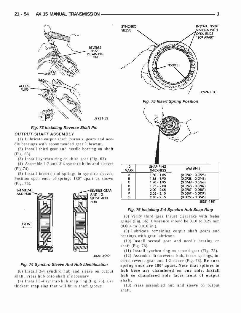
(7) Install 3-4 synchro hub snap ring (Fig. 76). Usethickest snap ring that will fit in shaft groove.
(8) Verify third gear thrust clearance with feelergauge (Fig. 56). Clearance should be 0.10 to 0.25 mm(0.004 to 0.010 in.).
(9) Lubricate remaining output shaft gears andbearings with gear lubricant.
(10) Install second gear and needle bearing onshaft (Fig. 78).
(11) Install synchro ring on second gear (Fig. 78).(12) Assemble first/reverse hub, insert springs, in-
serts, reverse gear and 1-2 sleeve (Fig. 78). Be surespring ends are 180° apart. Note that splines inhub bore are chamfered on one side. Installhub so chamfered side faces front of outputshaft.
(13) Press assembled hub and sleeve on outputshaft.
Fig. 73 Installing Reverse Shaft Pin
Fig. 74 Synchro Sleeve And Hub Identification
Fig. 75 Insert Spring Position
Fig. 76 Installing 3-4 Synchro Hub Snap Ring
21 - 54 AX 15 MANUAL TRANSMISSION J

(14) Install selective snap ring (Fig. 78). Use thick-est snap ring that will fit in output shaft groove.
(15) Install synchro ring on first gear (Fig. 79).(16) Install first gear spacer on shaft and against
selective fit snap ring (Fig. 79).(17) Install first gear and needle bearing (Fig. 79)
on output shaft.(18) Install locating pin and thrust washer on
shaft (Fig. 79).(19) Press rear bearing on shaft. Position bearing
snap ring groove so it is closest to end of outputshaft.
(20) Check first and second gear thrust clearancewith feeler gauge (Fig. 62).
• First gear clearance should be 0.10 to 0.40 mm(0.003 to 0.0197 in.)• Second gear clearance should be 0.10 to 0.30 mm(0.003 to 0.0118 in.)
(21) Press fifth gear onto output shaft. Then installselect fit snap ring (Fig. 80). Use thickest snap ringthat will fit in shaft groove.
(22) Lubricate input shaft pilot bearing with petro-leum jelly and install bearing in shaft (Fig. 60).
Fig. 77 Checking Third Gear Clearance
Fig. 78 Second Gear And Synchro Assembly
Fig. 79 First And Fifth Gear Components
Fig. 80 Selecting Fifth Gear Snap Ring
J AX 15 MANUAL TRANSMISSION 21 - 55

(23) Install input shaft on output shaft (Fig. 59).Be sure output shaft hub is fully seated in pilot bear-ing.
OUTPUT SHAFT AND CLUSTER GEARINSTALLATION
(1) Mount intermediate plate in vise (Fig. 24).(2) Lubricate cluster gear journal and rear bearing
with petroleum jelly or gear lubricant.(3) Install cluster gear rear bearing in intermedi-
ate plate (Fig. 81). Be sure snap ring groove in bear-ing is rearward as shown.
(4) Start cluster gear into bearing (Fig. 57). Thenhold bearing and push gear into place. Use plastic orrawhide mallet to seat bearing if necessary.
(5) Start output shaft rear bearing in intermediateplate. Push shaft rearward and tap intermediateplate with mallet to seat bearing.
(6) Install snap rings on cluster and output shaftrear bearings only (Fig. 82). Do not install frontbearing snap rings at this time.
(7) Install reverse idler gear and shaft (Fig. 83).
(8) Position rear bearing retainer over output shaftand rear bearing. Be sure bearing retainer tab isengaged in reverse idler shaft notch (Fig. 84).
(9) Install and tighten rear bearing retainer boltsto 18 Nzm (13 ft-lbs).
SHIFT RAIL AND FORK INSTALLATIONThe shift rail interlock pins, balls and plugs must
be installed in the correct sequence for proper shift-ing. Refer to the installation diagram (Fig. 85) duringassembly.
Coat the intermediate plate shift rail boresand the interlock balls, pins and plugs with athick covering of petroleum jelly before assem-bly. The jelly will hold the interlock compo-nents in place making installation easier. Use apencil magnet to hold and insert the interlocks.Then use a small screwdriver to push the inter-lock components into place.
(1) Coat reverse rail interlock pin with petroleumjelly and install pin in rail (Fig. 86).
(2) Install reverse shift rail in intermediate plate(Fig. 87).
Fig. 81 Installing Cluster Gear Rear Bearing
Fig. 82 Installing Rear Bearing Snap Rings
Fig. 83 Installing Reverse Idler Gear And Shaft
Fig. 84 Installing Rear Bearing Retainer
21 - 56 AX 15 MANUAL TRANSMISSION J

(3) Install reverse shift rail C-ring (Fig. 51).
Fig. 85 Shift Rail Ball-Plug-Pin Position
Fig. 86 Installing Reverse Shift Rail Interlock Pin
Fig. 87 Installing Reverse Shift Rail And Fork
J AX 15 MANUAL TRANSMISSION 21 - 57

(4) Position 1-2 and 3-4 shift forks in synchrosleeves (Fig. 88).
(5) Coat reverse rail lock ball with petroleum jelly.Then tilt reverse shift fork upward and insert ball inintermediate plate (Fig. 89).
(6) Coat 1-2 shift rail interlock plug with petro-leum jelly and install it in intermediate plate bore(Fig. 90).
(7) Coat 1-2 shift rail interlock pin with petroleumjelly and insert it in shift rail (Fig. 91).
(8) Install 1-2 shift rail in intermediate plate and1-2 fork (Fig. 92).
Fig. 88 Shift Fork Installation
Fig. 89 Installing Reverse Shift Rail Lock Ball
Fig. 90 Installing 1-2 Shift Rail Interlock Plug
Fig. 91 Installing 1-2 Shift Rail Interlock Pin
Fig. 92 Installing 1-2 Shift Rail
21 - 58 AX 15 MANUAL TRANSMISSION J

(9) Coat 3-4 shift rail interlock plug with petro-leum jelly and install plug in intermediate plate (Fig.93).
(10) Install 3-4 shift rail in intermediate plate andin both shift forks (Fig. 94).
(11) Verify that none of the interlock balls, plugs,or pins were displaced during shift rail installation.
(12) Install and tighten shift fork setscrews to 20Nzm (14 ft. lbs.) torque (Fig. 95).
(13) Install 1-2 and 3-4 shift rail C-rings (Fig. 96).(14) Insert fifth gear shift rail through reverse
shift fork. Then slide rail into intermediate platejust far enough to secure interlock ball. Do notfully install shift rail at this time.
FIFTH-REVERSE GEAR AND SHIFTCOMPONENT INSTALLATION
(1) Install thrust ring lock ball in cluster gear jour-nal (Fig. 97). Use petroleum jelly to hold ball inplace.
Fig. 93 Installing 3-4 Shift Rail Interlock Plug
Fig. 94 Installing 3-4 Shift Rail
Fig. 95 Installing Shift Fork Set Screws
Fig. 96 Installing Shift Rail C-Rings
Fig. 97 Installing Thrust Ring Lock Ball
J AX 15 MANUAL TRANSMISSION 21 - 59

(2) Install fifth gear thrust ring (Fig. 98). Be surethrust ring notch fits over lock ball.
(3) Assemble counter fifth gear, synchro sleeve, in-serts and insert springs (Fig. 99).
(4) Lubricate two-piece bearing with petroleumjelly and install it in counter fifth gear (Fig. 100).
(5) Install counter fifth gear and synchro assemblyon cluster gear journal (Fig. 101).
(6) Install synchro ring in synchro sleeve (Fig.102).
Fig. 98 Installing Fifth Gear Thrust Ring
Fig. 99 Assembling Fifth Gear And SynchroAssembly
Fig. 100 Installing Counter Fifth Gear Bearing
Fig. 101 Installing Counter Fifth Gear And Sleeve
Fig. 102 Installing Fifth Gear Synchro Ring
21 - 60 AX 15 MANUAL TRANSMISSION J

(7) Install fifth spline gear on cluster journal (Fig.103). Tap spline gear into place with plastic mallet ifnecessary.
(8) Install fifth gear selective snap ring (Fig. 104).Use thickest snap ring that will fit in shaft groove.
(9) Install reverse shift head and rail (Fig. 105).Then install lock ball in shift head.
(10) Position fifth gear shift fork in synchro sleeve(Fig. 106).
(11) Install fifth gear shift rail (Fig. 107). Slide railthrough fork, shift head, intermediate plate and re-verse shift fork. Be sure interlock ball is not dis-placed during installation.
Fig. 103 Installing Fifth Spline Gear
Fig. 104 Installing Fifth Gear Snap Ring
Fig. 105 Installing Reverse Shift Head And Rail
Fig. 106 Fifth Gear Shift Fork Installation
Fig. 107 Fifth Gear Shift Rail Installation
J AX 15 MANUAL TRANSMISSION 21 - 61

(12) Align screw holes in shift fork and rail and in-stall set screw (Fig. 108). Tighten screw to 20 Nzm(15 ft. lbs.) torque.
(13) Install lock balls and springs in intermediateplate (Fig. 109). Then install and tighten lock ballplugs to 19 Nzm (14 ft. lbs.) torque.
(14) Install reverse shift arm bracket (Fig. 110).Tighten bracket bolts to 18 Nzm (13 ft. lbs.) torque.
(15) Install reverse shift arm (Fig. 110). Positionarm on reverse fork pin and engage it with pin onshift arm bracket.
(16) Verify that shift arm shoe is engaged in re-verse idler gear. Then secure shift arm to pin on re-verse fork with new E-clip.
GEAR CASE AND ADAPTER INSTALLATION(1) Dismount intermediate plate and gear assem-
blies from vise.(2) Clean mating surfaces of intermediate plate
and transmission gear case with wax and grease re-mover. Then wipe dry with a clean cloth.
(3) Apply 3 mm (1/8 in.) wide bead of Mopar Gas-ket Maker, or Loctite 518 to mating surface of gearcase. Keep sealer bead inside bolt holes as shown(Fig. 111).
Fig. 108 Shift Fork Set Screw Installation
Fig. 109 Detent Ball And Spring Installation
Fig. 110 Reverse Shift Arm And Bracket Installation
Fig. 111 Applying Sealer To Gear Case
21 - 62 AX 15 MANUAL TRANSMISSION J

(4) Install gear case (Fig. 112). Align shift rails andbearings in case and tap case into position.
(5) Verify that gear case is seated on intermediateplate dowel pins.
(6) Install front bearing snap rings (Fig. 113).
(7) Clean gear case and front bearing retainer seal-ing surfaces with wax and grease remover. Thenwipe dry with a clean cloth.
(8) Install new seal in front bearing retainer. Thenlubricate seal lip with petroleum jelly. Installationdepth for seal is 10.5 to 11.5 mm (0.413 to 0.453in.).
(9) Apply a 3 mm (1/8 in.) wide bead of MoparGasket Maker, or Loctite 518 to front bearing re-tainer sealing surface.
(10) Align and install front bearing retainer (Fig.114). Be sure retainer is properly seated on case andbearings.
(11) Install and tighten front bearing retainer boltsto 17 Nzm (12 ft. lbs.) torque.
(12) On models with extension housing, installspeedometer gear, lock ball and retaining rings (Fig.115). Be sure lock ball is engaged in gear.
(13) Inspect condition of reverse pin in adapter/ex-tension housing (Fig. 116). If pin is worn or damaged,replace it as follows:
(a) Remove roll pin access plug (Fig. 117).(b) Tap roll pin out of housing with pin punch
(Fig. 118). Then remove old reverse pin.(c) Install new reverse pin and secure it with roll
pin. Then install and tighten access plug to 19 Nzm(14 ft. lbs.) torque.(14) Clean sealing surfaces of adapter or extension
housing and intermediate plate with wax and greaseremover. Then wipe dry with a clean cloth.
Fig. 112 Gear Case Installation
Fig. 113 Front Bearing Snap Ring Installation
Fig. 114 Installing Front Bearing Retainer
Fig. 115 Speedometer Gear Installation (2WDModels)
J AX 15 MANUAL TRANSMISSION 21 - 63

(15) Apply 3 mm (1/8 in.) wide bead of Mopar Gas-ket Maker, or Loctite 518 to sealing surface ofadapter or extension housing. Keep sealer bead in-side bolt holes as shown in Figure 111.
(16) Align and install adapter or extension housingon intermediate plate (Fig. 119). Be sure housing isseated on intermediate plate dowel pins.
(17) Coat threads of housing attaching bolts withMopar silicone sealer. Then install and tighten boltsto 37 Nzm (27 ft. lbs.) torque.
(18) Install detent ball (Fig. 120).
(19) Install detent spring (Fig. 121).
Fig. 116 Reverse Pin Position
Fig. 117 Access Plug Removal/Installation
Fig. 118 Roll Pin Removal/Installation
Fig. 119 Adapter/Extension Housing Installation
Fig. 120 Installing Detent Ball
Fig. 121 Installing Detent Spring
21 - 64 AX 15 MANUAL TRANSMISSION J

(20) Install detent access plug (Fig. 122). Tightenplug to 19 Nzm (14 ft. lbs.) torque.
(21) Lubricate shift arm shaft and install it inadapter housing (Fig. 123).
(22) Position shift arm in adapter housing (Fig.124). Be sure arm is engaged in shift rails.
(23) Align shift arm with shaft and push shaft intoarm.
(24) Rotate shift arm shaft until set screw holes inshaft and arm are aligned.
(25) Install and tighten shift arm set screw to 38Nzm (28 ft. lbs.) torque (Fig. 125).
(26) Install and tighten restrictor pins to 19 Nzm(14 ft. lbs.) torque (Fig. 125).
(27) Install and tighten shift arm shaft access plugto 19 Nzm (14 ft. lbs.) torque (Fig. 126).
Fig. 122 Installing Detent Access Plug
Fig. 123 Installing Shift Arm Shaft
Fig. 124 Shift Arm Installation
Fig. 125 Set Screw And Restrictor Pin Installation
Fig. 126 Access Plug Installation
J AX 15 MANUAL TRANSMISSION 21 - 65

(28) Position new shift tower gasket on adapterhousing (Fig 127).
(29) Install shift tower (Fig. 128). Tighten towerattaching bolts to 18 Nzm (13 ft. lbs.) torque.
(30) Install new gasket on backup light switch andinstall switch. Tighten switch to 37 Nzm (27 ft. lbs.)torque.
(31) Install new washer on drain plug. Then installand tighten plug to 37 Nzm (27 ft. lbs.) torque.
(32) If transmission will be filled with gear lubri-cant before installation, place transmission in a levelposition. Then fill with Mopar 75W-90, grade GL-5gear lubricant.
(33) Install new washer on fill plug. Then installand tighten plug to 37 Nzm (27 ft. lbs.) torque.
(34) Install clutch housing and hydraulic concen-tric bearing.
(35) On models with extension housing, install newseal in housing with suitable size installer tool (Fig.129). Lubricate seal lips with petroleum jelly beforeinstallation.
(36) On models with extension housing, installspeedometer driven gear, speedometer adapter andspeed sensor.
Fig. 127 Shift Tower Gasket Installation
Fig. 128 Shift Tower Installation
Fig. 129 Installing Extension Housing Seal
21 - 66 AX 15 MANUAL TRANSMISSION J

30RH/32RH AUTOMATIC TRANSMISSION
GENERAL INFORMATION
INDEX
page page
Recommended Fluid . . . . . . . . . . . . . . . . . . . . . . . 67Torque Converter . . . . . . . . . . . . . . . . . . . . . . . . . 67Transmission Application . . . . . . . . . . . . . . . . . . . . 67
Transmission Changes and Parts Interchangeability . . 67Transmission Controls and Components . . . . . . . . 67Transmission Identification . . . . . . . . . . . . . . . . . . 67
TRANSMISSION APPLICATIONChrysler 30RH and 32RH automatic transmissions
are used in XJ/YJ models. Both are 3-speed auto-matic transmissions with a gear-type oil pump, twoclutches and bands and a planetary gear system (Fig.1).
The 30RH is used in XJ/YJ models with a 2.5L en-gine. The 32RH is used in YJ models with a 4.0L en-gine.
TORQUE CONVERTERA three element, torque converter is used for all
applications. The converter consists of an impeller,stator, and turbine.
The converter used with 30RH/32RH transmissionshas a converter clutch. The clutch is engaged by anelectrical solenoid and mechanical module on thevalve body. The solenoid is operated by the power-train control module.
The torque converter is a welded assembly and isnot a repairable component. The converter is servicedas an assembly.
RECOMMENDED FLUIDThe recommended and preferred fluid for 30RH/
32RH transmissions is Mopar ATF Plus, Type 7176.Dexron II is not really recommended and should
only be used when ATF Plus is not available.
TRANSMISSION IDENTIFICATIONThe transmission identification numbers are
stamped on the left side of the case just above the oilpan gasket surface (Fig. 2). The first set of numbersis the transmission part number. The next set of codenumbers set is the date of build. The final set of codenumbers represents the transmission serial number.
TRANSMISSION CHANGES AND PARTSINTERCHANGEABILITY
1995 transmissions are similar to previous modelsbut only in appearance. Current transmissions aredimensionally different. Do not interchange new/old
parts. Different dimensions, fluid passages, input/output shafts, cases, bands, valve bodies and gover-nor assemblies are just a few of the changed items.
CAUTION: Special bolts are used to attach thedriveplate to the crankshaft on models with a 2.5Lengine and 30RH transmission,. These bolts have asmaller hex head for torque converter clearance.DO NOT interchange these bolts with similar sizebolts for any reason.
Different governor weight assemblies are used in30RH/32RH transmissions. The 30RH weight assem-bly is much the same as in previous years. However,the 32RH has a three stage governor weight assem-bly consisting of the outer weight, a smaller weightspring, and a new intermediate weight. Refer to theoverhaul and in-vehicle service sections for more de-tailed information.
Plastic check balls are now used in many 30RH/32RH valve bodies. The new check balls entered pro-duction as a running change. Plastic and steel checkballs are not interchangeable.
A converter drainback check valve has been addedto the fluid cooler system. The one-way valve is lo-cated in the transmission outlet (pressure) line. Thevalve prevents fluid drainback when the vehicle isparked for lengthy periods.
TRANSMISSION CONTROLS AND COMPONENTSThe transmission hydraulic control system per-
forms five basic functions, which are:• pressure supply• pressure regulation• flow control• clutch/band apply and release• lubrication
Pressure Supply And RegulationThe oil pump generates the fluid working pressure
needed for operation and lubrication. The pump is
J 30RH/32RH AUTOMATIC TRANSMISSION 21 - 67

Fig. 1 30RH/32RH Automatic Transmission
21 - 68 30RH/32RH AUTOMATIC TRANSMISSION J

driven by the torque converter. The converter is con-nected to the engine crankshaft through the drive-plate.
The pressure regulator valve maintains line pres-sure. The regulator valve is located in the valve body.The amount of line pressure developed is controlledby throttle pressure, which is dependent on the de-gree of throttle opening.
The governor valve is operated by the transmissionoutput shaft. Governor pressure increases approxi-mately in proportion to vehicle speed.
The throttle valve determines line pressure andshift speed. The throttle valve also controls upshiftand downshift speeds by regulating pressure in con-junction with throttle position.
Shift ValvesThe manual valve is operated by the gearshift link-
age and provides the operating range selected by thedriver.
The 1-2 shift valve provides automatic 1-2 or 2-1shifts and the 2-3 shift valve provides automatic 2-3or 3-2 shifts. The kickdown valve provides forced 3-2or 3-1 downshifts depending on vehicle speed. Down-shifts occur when the throttle is opened beyonddownshift detent position which is just before wideopen throttle.
The 2-3 valve throttle pressure plug provides 3-2downshifts with varying throttle openings and de-pending on vehicle speed. The 1-2 shift control valvetransmits 1-2 shift pressure to the accumulator pis-ton to control kickdown band capacity on 1-2 upshiftsand 3-2 downshifts.
The shuttle valve has two functions. First is fastfront band release and smooth engagement duringlift-foot 2-3 upshifts. The second is to regulate frontclutch and band application during 3-2 downshifts.
Clutches-Bands-Servos-AccumulatorThe front/rear clutch pistons and servo pistons are
actuated by line pressure. When line pressure is re-moved, the pistons are released by spring tension.
On 2-3 upshifts, the front servo piston is releasedby spring tension and hydraulic pressure. The accu-mulator controls hydraulic pressure on the apply sideof the front servo during 1-2 upshifts and at allthrottle openings.
Converter Clutch ControlsConverter clutch operation is controlled by the
power train control module, and by the solenoid andclutch module on the valve body. The solenoid is op-erated by a relay on the engine compartment side ofthe dash panel.
Activating the solenoid opens a vent allowing fluidto flow into the clutch module. When line pressureexceeds tension of the module valve springs, themodule valves open. This allows fluid to be chan-neled to the converter clutch through the reactionshaft support and transmission shaft.
Gearshift And Park Lock ControlsThe gearshift lever provides six operating positions:
Park (P), Reverse (R), Neutral (N), and the D, 2 and1 forward drive ranges.
Manual 1 position provides first gear only. Overrunbraking occurs in 1 range when the throttle is re-leased. Upshifts are not provided in 1 range.
Manual 2 range provides first and second gear. A1-2 upshift will take place but a 2-3 upshift will notoccur.
D position provides 1-2, 2-3 upshifts and 3-2 and3-1 downshifts.
Park position allows the park rod to move the parkpawl into engagement with the park gear. This pre-vents rotation of the transmission output shaft. Thepark lock mechanism is only engaged when the shiftlever is in the Park detent.
A park/neutral position switch controls enginestarting. The switch is designed to allow enginestarts only in park or neutral positions.
Fig. 2 Transmission Identification
J 30RH/32RH AUTOMATIC TRANSMISSION 21 - 69

30RH/32RH TRANSMISSION DIAGNOSIS
INDEX
page page
Air Pressure Test . . . . . . . . . . . . . . . . . . . . . . . . . 74Analyzing the Road Test . . . . . . . . . . . . . . . . . . . . 71Converter Housing Leak Diagnosis . . . . . . . . . . . . 75Converter Stall Test . . . . . . . . . . . . . . . . . . . . . . . . 74Diagnosis Guides and Charts . . . . . . . . . . . . . . . . 77Effects of Incorrect Fluid Level . . . . . . . . . . . . . . . 71Fluid Level Check . . . . . . . . . . . . . . . . . . . . . . . . . 70
Gearshift Cable/Linkage Adjustment . . . . . . . . . . . 71General Information . . . . . . . . . . . . . . . . . . . . . . . 70Hydraulic Pressure Test . . . . . . . . . . . . . . . . . . . . 72Preliminary Diagnosis . . . . . . . . . . . . . . . . . . . . . . 70Road Test . . . . . . . . . . . . . . . . . . . . . . . . . . . . . . . 71Transmission Throttle Valve Cable Adjustment . . . . 71
GENERAL INFORMATIONAutomatic transmission problems are generally a
result of:• poor engine performance• incorrect fluid level• incorrect throttle valve cable adjustment• incorrect band adjustment• incorrect hydraulic control pressure adjustments• hydraulic component malfunctions• mechanical component malfunctions.
Begin diagnosis by checking the easily accessibleitems such as fluid level, fluid condition and controllinkage adjustment. A road test will determine if fur-ther diagnosis is necessary.
Procedures outlined in this section should be per-formed in the following sequence to realize the mostaccurate results:• Preliminary diagnosis• Check fluid level and condition• Check control linkage Adjustment• Road test• Stall test• Hydraulic pressure test• Air pressure tests• Leak test• Analyze test results and consult diagnosis charts
PRELIMINARY DIAGNOSISTwo basic procedures are required. One procedure
for vehicles that are driveable and an alternate pro-cedure for disabled vehicles (will not back up or moveforward).
Vehicle Is Driveable(1) Check fluid level and condition.(2) Adjust throttle cable and gearshift linkage if
complaint was based on delayed, erratic, or harshshifts.
(3) Road test vehicle and note transmission operat-ing characteristics.
(4) Perform stall test if complaint is based on slug-gish, low speed acceleration or abnormal throttleopening needed to maintain normal speeds withproperly tuned engine.
(5) Perform hydraulic pressure tests.(6) Perform air pressure test to check clutch-band
operation.
Vehicle Is Disabled(1) Check fluid level and condition.(2) Check for broken, disconnected throttle linkage.(3) Check for cracked, leaking cooler lines, or loose,
missing pressure port plugs.(4) Raise vehicle, start engine, shift transmission
into gear and note following:(a) If propeller shafts turn but wheels do not,
problem is with differential or axle shafts.(b) If propeller shafts do not turn and transmis-
sion is noisy, stop engine. Remove oil pan, andcheck for debris. If pan is clear, remove transmis-sion and check for damaged drive plate, converter,oil pump or input shaft.
(c) If propeller shafts do not turn and transmis-sion is not noisy, perform hydraulic pressure test todetermine if problem is a hydraulic or mechanical.
FLUID LEVEL CHECKTransmission fluid level should be checked monthly
under normal operation. If the vehicle is used fortrailer towing or similar heavy load hauling, checkfluid level and condition weekly.
Fluid level is checked with the engine running atcurb idle speed, the transmission in Neutral and thetransmission fluid at normal operating temperature.
FLUID LEVEL CHECK PROCEDURE(1) Transmission fluid must be at normal operating
temperature for accurate fluid level check. Drive ve-hicle if necessary to bring fluid temperature up tonormal hot operating temperature of 82°C (180°F).
(2) Position vehicle on level surface. This is ex-tremely important for accurate fluid level check.
(3) Start and run engine at curb idle speed.
21 - 70 30RH/32RH TRANSMISSION DIAGNOSIS J

(4) Apply parking brakes.(5) Shift transmission momentarily into all gear
ranges. Then shift transmission back to Neutral.(6) Clean top of filler tube and dipstick to keep dirt
from entering tube.(7) Remove dipstick and check fluid level as fol-
lows:(a) Dipstick has three fluid level indicator levels
(Fig. 1) which are: a MIN dot, an OK crosshatcharea, and a MAX fill arrow.
(b) Correct maximum level is to MAX arrowmark. Correct acceptable level is to OK mark incrosshatch area.
(c) Incorrect level is at or below MIN dot.(d) If fluid is low, add only enough Mopar ATF
Plus to restore correct level. Do not overfill.
CAUTION: Do not overfill the transmission. Overfill-ing may cause leakage out the pump vent whichcan be mistaken for a pump seal leak. Overfillingwill also cause fluid aeration and foaming as the ex-cess fluid is picked up and churned by the geartrain. This will significantly reduce fluid life.
EFFECTS OF INCORRECT FLUID LEVELA low fluid level allows the pump to take in air
along with the fluid. Air in the fluid will cause fluidpressures to be low and develop slower than normal.
If the transmission is overfilled, the gears churnthe fluid into foam. This aerates the fluid causing thesame conditions that occur with a low level.
In either case, air bubbles cause fluid overheating,oxidation and varnish buildup which interferes withvalve, clutch and servo operation. Foaming alsocauses fluid expansion which can result in fluid over-flow from the transmission vent or fill tube. Fluidoverflow can easily be mistaken for a leak if inspec-tion is not careful.
TRANSMISSION THROTTLE VALVE CABLEADJUSTMENT
Throttle cable adjustment is important to properoperation. This adjustment positions the throttlevalve which controls shift speed, quality and partthrottle downshift sensitivity.
If cable adjustment setting is too short, early shiftsand slippage between shifts may occur. If the settingis too long, shifts may be delayed and part throttledownshifts may be very sensitive. Refer to the In-Ve-hicle Service section for adjustment procedure.
GEARSHIFT CABLE/LINKAGE ADJUSTMENTGearshift cable/linkage adjustment is important be-
cause it positions the valve body manual valve. Incor-rect adjustment will cause creeping in Neutral,premature clutch wear, delayed engagement in anygear, or a no-start in Park or Neutral position.
Proper operation of the neutral start switch willprovide a quick check on adjustment. Refer to the In-Vehicle Service section for adjustment procedure.
ROAD TESTBefore road testing, be sure the fluid level and all
cable/linkage adjustments have been checked and ad-justed if necessary.
Observe engine performance during the road test. Apoorly tuned engine will not allow an accurate anal-ysis of transmission operation.
Operate the transmission in all gear ranges. Checkfor slippage and shift variations. Note whether theshifts are harsh, spongy, delayed, early, or if partthrottle downshifts are sensitive.
Watch closely for slippage or engine flare whichusually indicates clutch, band or overrunning clutchproblems. If the condition is advanced, an overhaulmay be necessary to restore normal operation.
A slipping clutch or band can often be determinedby comparing which internal units are applied in thevarious gear ranges. The Clutch and Band Applica-tion chart (Fig. 3) provides a basis for analyzing roadtest results.
ANALYZING THE ROAD TESTRefer to the Clutch and Band Application chart
(Fig. 3) and note which elements are in use in thevarious gear ranges.
The rear clutch is applied in all forward ranges (D,2, 1). The overrunning clutch is applied in first gear(D and 2 range only). The rear band is applied in 1and R range only.
For example: If slippage occurs in first gear in Dand 2 range but not in 1 range, the overrunning
Fig. 3 Clutch And Band Application Chart
J 30RH/32RH TRANSMISSION DIAGNOSIS 21 - 71

clutch is slipping. Similarly, if slippage occurs in anytwo forward gears, the rear clutch is slipping.
Applying the same method of analysis, note thatboth clutches are applied in D range third gear only.If the transmission slips in third gear, either thefront clutch or the rear clutch is slipping. By select-ing another gear which does not use one of theseunits, the slipping clutch can be determined.
Although road test analysis will help determine theslipping unit, the actual cause of a malfunction maynot be determined until hydraulic and air pressuretests are performed. Practically any condition can becaused by leaking hydraulic circuits or stickingvalves. Unless the problem is an obvious one, do notremove and disassemble the transmission until hy-draulic and air pressure tests have been performed.
HYDRAULIC PRESSURE TESTHydraulic test pressures range from a low of one
psi (6.895 kPa) governor pressure, to 300 psi (2068.5kPa) at the rear servo pressure port in reverse.
Use 100 psi Pressure Gauge C-3292 to check pres-sure at the accumulator, front servo, governor andfluid cooler line. Use 300 psi Gauge C-3293 to checkpressure at the rear servo. The 300 psi gauge can beused at any other port when more than one gauge isrequired for testing.
PRESSURE TEST PORT LOCATIONSThere are pressure test ports at the accumulator,
front servo, rear servo and governor.Line pressure is checked at the accumulator port
on the right side of the case (Fig. 4). The front servorelease pressure port is at the right side of the casejust behind the filler tube opening (Fig. 4).
The rear servo pressure port is at the right rear ofthe transmission case (Fig. 5).
On 4 x 2 models, the governor pressure port is atthe left side of case at the transmission rear (Fig. 5).On 4 x 4 transmissions, the test port is in the driverside of the adapter housing (Fig. 6).
PRESSURE TEST PROCEDUREConnect a tachometer to the engine. Position the
tachometer so it can be observed from under the ve-hicle. Raise the vehicle on a hoist that will allow thewheels to rotate freely.
Test One-Transmission In 1 RangeThis test checks pump output, pressure regu-
lation, and condition of the rear clutch andrear servo circuits. Use both test gauges forthis test
(1) Connect Test Gauge C-3292 to line pressureport and Test Gauge C-3293 to rear servo port (Figs.4-6).
(2) Disconnect throttle and gearshift rods at trans-mission.
(3) Start and run engine at 1000 rpm.(4) Move valve body selector lever forward into 1
range.(5) Read pressures on both gauges as transmission
throttle lever is moved from full forward to full rear-ward position.
(a) Line pressure should be 54-60 psi (372-414kPa) with throttle lever forward and gradually in-crease to 90-96 psi (620-662 kPa) as lever is movedrearward.
(b) Rear servo pressure should be same as linepressure within 3 psi.
Fig. 4 Front Servo And Line Pressure Test Ports
Fig. 5 Rear Servo And Governor Pressure TestPorts ( 4 x 2 Transmission)
Fig. 6 Governor Pressure Test Port (4 x 4Transmission)
21 - 72 30RH/32RH TRANSMISSION DIAGNOSIS J

Test Two-Transmission In 2 RangeThis test checks pump output and pressure
regulation. Use 100 psi Test Gauge C-3292 forthis test.
(1) Connect test gauge to line pressure port (Fig.4).
(2) Start and run engine at 1000 rpm.(3) Move valve body selector lever one detent rear-
ward from full forward position (this is 2 range).(4) Move transmission throttle lever from full for-
ward to full rearward position and read pressure atboth gauges.
(5) Line pressure should be 54-60 psi (372-414kPa) with throttle lever forward and gradually in-crease to 90-96 psi (620-662 kPa) as lever is movedrearward.
Test Three-Transmission In Third GearThis test checks pressure regulation and con-
dition of the front and rear clutch circuits.Both gauges are required for this test.
(1) Connect one test gauge to line pressure portand other gauge to front servo pressure port (Fig. 4).Either gauge can be used at either port.
(2) Start and run engine at 1600 rpm.(3) Move selector lever two detents rearward from
full forward position. This is D range.(4) Read pressures on both gauges as transmission
throttle lever is moved from full forward to full rear-ward position.
(a) Line pressure in third gear, should be 54-60psi (372-414 kPa) with throttle lever forward andgradually increase as lever is moved rearward.
(b) Front servo pressure in third gear, should bewithin 3 psi (21 kPa) of line pressure, up to down-shift point.
Test Four-Transmission In ReverseThis test checks pump output, pressure regu-
lation and the front clutch and rear servo cir-cuits. Use 300 psi Pressure Test Gauge C-3293for this test.
(1) Connect pressure test gauge to rear servo port(Fig. 5).
(2) Start and run engine at 1600 rpm for test.(3) Move valve body selector lever four detents
rearward from full forward position. This is Reverserange.
(4) Move throttle lever all way forward then all theway rearward and note gauge readings.
(5) Pressure should be 145 - 175 psi (1000-1207kPa) with lever forward and increase to 230 - 280 psi(1586-1931 kPa) as lever is moved rearward.
Test Five-Governor PressureThis test checks governor operation by mea-
suring governor pressure response to changes
in engine speed. It is usually not necessary tocheck governor operation unless shift speedsare incorrect or if the transmission will notshift up or down. Use 100 psi Pressure TestGauge C-3292 for this test.
(1) Connect test gauge to governor pressure port(Figs. 5 and 6).
(2) Move selector lever to D range.(3) Apply service brakes. Start and run engine at
curb idle speed and note pressure. At idle and withwheels stopped, pressure should be zero to 1-1/2 psimaximum. If pressure exceeds this figure, governorvalve or weights are sticking open.
(4) Slowly increase engine speed and observespeedometer and pressure test gauge. Governor pres-sure should increase in proportion to vehicle speed(approximately 1 psi for every 1 mph shown onspeedometer).
(5) Governor pressure rise should be smooth anddrop back to 0 to 1-1/2 psi when throttle is closedand wheels are stopped.
(6) Compare results of pressure tests with analysischart (Fig. 7).
Fig. 7 Pressure Test Analysis Chart
J 30RH/32RH TRANSMISSION DIAGNOSIS 21 - 73

CONVERTER STALL TESTStall testing involves determining maximum engine
rpm obtainable at full throttle with the rear wheelslocked and the transmission in D range. This testchecks the holding ability of the converter overrun-ning clutch and both of the transmission clutches.When stall testing is completed, refer to the StallSpeed Specifications chart and Stall Speed Diagnosisguides.
WARNING: NEVER ALLOW ANYONE TO STAND INFRONT OF THE VEHICLE DURING A STALL TEST.ALWAYS BLOCK THE FRONT WHEELS AND APPLYTHE SERVICE AND PARKING BRAKES DURINGTHE TEST.
STALL TEST PROCEDURE(1) Connect tachometer to engine.(2) Check and adjust transmission fluid level.(3) Start and run engine until transmission fluid
reaches normal operating temperature.(4) Block front wheels.(5) Fully apply service and parking brakes.(6) Open throttle completely and record maximum
engine rpm registered on tachometer. It will takefrom 3 to 10 seconds to reach maximum rpm. How-ever, once maximum rpm has been achieved, do nothold wide open throttle for more than 5 sec-onds.
CAUTION: Stalling the converter causes a rapid in-crease in fluid temperature. To avoid fluid overheat-ing, hold wide open throttle for no more than 5seconds after reaching peak rpm. In addition, ifmore than one stall test is required, run the engineat 1000 rpm with the transmission in Neutral for atleast 20 seconds to cool the fluid.
(7) Stall speeds should be in 1700-2150 rpm range.
CAUTION: If engine exceeds 2150 rpm, release ac-celerator pedal immediately as transmission clutchslippage is occurring.
(8) Shift transmission into Neutral. Run engine for20-30 seconds at 1000 rpm to cool fluid. Then stopengine, shift transmission into Park and releasebrakes.
(9) Refer to Stall Test Diagnosis.
STALL TEST DIAGNOSIS
Stall Speed Too LowLow stall speeds with a properly tuned engine in-
dicate a torque converter overrunning clutch prob-lem. The condition should be confirmed by roadtesting prior to converter replacement.
The converter overrunning clutch is slipping whenstall speeds are 250 to 350 rpm below specified min-imum.
A converter overrunning clutch failure will resultin sluggish acceleration in all speed ranges. It willalso require greater than normal throttle opening tomaintain cruising speeds.
Stall Speed Too HighIf stall speed exceeds 2150 rpm, transmission
clutch slippage is occurring.
Stall Speed Normal But Acceleration Is SluggishIf stall speeds are within specified range but abnor-
mal throttle opening is required for acceleration, orto maintain cruise speeds, the converter overrunningclutch is seized. The torque converter will have to bereplaced.
Converter Noise During TestA whining noise caused by fluid flow is normal dur-
ing a stall test. However, loud metallic noises indi-cate a damaged converter. To confirm that noise isoriginating from the converter, operate the vehicle atlight throttle in Drive and Neutral on a hoist and lis-ten for noise from the converter housing.
AIR PRESSURE TESTAir pressure testing can be used to check clutch
and band operation with the transmission either inthe vehicle, or on the work bench as a final check af-ter overhaul.
Air pressure testing requires that the oil pan andvalve body be removed from the transmission.
The servo and clutch apply passages are shown inFigure 8.
Air Test Procedure(1) Place one or two fingers on the clutch housing
and apply air pressure through front clutch applypassage (Fig. 8). Piston movement can be felt and asoft thud heard as the clutch applies.
(2) Place one or two fingers on the clutch housingand apply air pressure through rear clutch applypassage (Fig. 8). Piston movement can be felt and asoft thud heard as the clutch applies.
(3) Apply air pressure to the front servo apply pas-sage. The servo rod should extend and cause theband to tighten around the drum. Spring tensionshould release the servo when air pressure is re-moved.
(4) Apply air pressure to the rear servo apply pas-sage. The servo rod should extend and cause theband to tighten around the drum. Spring tensionshould release the servo when air pressure is re-moved.
21 - 74 30RH/32RH TRANSMISSION DIAGNOSIS J

CONVERTER HOUSING LEAK DIAGNOSISTwo items must be established when diagnosing
leaks from the converter housing area. First, it mustbe verified that a leak condition actually exists. Andsecond, the true source of the leak must be deter-mined.
Some suspected converter housing fluid leaks maynot be leaks at all. Residual fluid in the housing, orexcess fluid spilled during factory fill or refill afterrepair can be mistaken for a leak. In addition, a rearmain seal leak can also be mistaken for a pump sealleak if care is exercised.
Converter housing leaks have several potentialsources. Through careful observation, a leak sourcecan be identified before removing the transmissionfor repair.
Pump seal leaks tend to move along the drive huband onto the rear of the converter. Pump O-ring orpump body leaks follow the same path as a seal leak(Fig. 9).
Pump vent or pump attaching bolt leaks are gener-ally deposited on the inside of the converter housingand not on the converter itself (Fig. 9).
Pump seal or gasket leaks usually travel down theinside of the converter housing.
Front band lever pin plug leaks are generally de-posited on the housing and not on the converter.
LEAK DIAGNOSIS PROCEDURE(1) Raise the rear of the vehicle and allow accumu-
lated fluid to drain out of the converter housing.(2) Check and adjust the transmission fluid level.(3) Raise the vehicle. Remove the converter hous-
ing dust cover and wipe as much fluid as possiblefrom the converter housing.
(4) Fabricate a test probe (Fig. 10). Then attachthe probe to the converter housing with one of thedust shield bolts (Fig. 10).
(5) Have a helper run the engine at 2500 rpm(with the transmission in Neutral) for two minutes;then stop the engine.
(6) Inspect the test probe and converter housing. Ifa leak is evident, note the color of the fluid. Trans-mission fluid is red. Engine oil ranges in color frombrown to green, or to black when the oil is dirty.
(7) If the probe upper surface is dry, the converterand seal are not at fault. A path of fluid across theprobe upper surface indicates a converter or sealleak. Fluid leaking under the probe is coming fromthe pump housing area (Fig. 11).
(8) Fluid leaking under the probe could be fromthe: pump seal and/or bushing, pump vent, kickdownlever shaft access plug, pump bolts, or porous spotsin the pump body or transmission case (Fig. 11).
(9) If porous spots in the transmission case orpump body are the suspected leak source, pressurizethe transmission as described in Leak Testing WithAir Pressure.
Fig. 8 Air Pressure Test Passages
Fig. 9 Typical Converter Housing Leak Paths
Fig. 10 Leak Test Probe
J 30RH/32RH TRANSMISSION DIAGNOSIS 21 - 75

LEAK TESTING WITH AIR PRESSUREThis test involves closing off the transmission open-
ings and pressurizing the transmission to 8 psi withAir Pump Tool 7700.
A soapy water solution is applied to suspected leakpoints before and during the pressure test. Leaks willbe indicated by the presence of air bubbles comingthrough the solution.
Some transmission openings such as the fill tubeand front cooler line fitting can be closed off with arubber plug or similar device. Plugs can secured withwire or duct tape.
The transmission rear output shaft opening isclosed off simply by leaving the transfer case boltedin place. However, if the transfer case has been re-moved, a shipping plug can used to close off thisopening.
The torque converter hub opening in the pump andthe pump vent require special tools to close them off.The converter hub seal cap is made from thin walltube and a 3 mm (1/8 in.) thick disc (Fig. 12). A re-taining strap is needed to secure the seal cup fortesting. The strap can be made from 32 mm (1-1/4in.) wide stock (Fig. 13). The strap attaching hole po-sitions are approximate only. Measure hole positionon the converter housing before drilling.
The pump vent tool is made from 6 mm (1/4 in.)rod and 5 mm (3/16 in.) plate (Fig. 14). The fabri-cated tools can all be made from mild steel or alumi-num stock.
AIR PRESSURE LEAK TEST PROCEDURE(1) Install vent plug, converter hub seal cup and
cup retaining strap (Fig. 15).(2) Close off remaining transmission openings with
rubber plugs, or stoppers. Do not close off rearcooler line fitting. Air pump will be attached tothis fitting.
(3) Attach Air Pump 7700 to rear cooler line fit-ting. Connect length of copper tube to fitting. Thenattach air pump hose to tube with hose clamp (Fig.16).
Fig. 11 Pump Area Inspection Points Fig. 12 Converter Hub Seal Cup
Fig. 13 Seal Cup Retaining Strap
Fig. 14 Pump Vent Plug
21 - 76 30RH/32RH TRANSMISSION DIAGNOSIS J

(4) Apply thick soapy water solution to suspectedleak areas.
CAUTION: The recommended test pressure is 8 psi.The maximum allowable test pressure is 10 psi. Donot exceed specified test pressure.
(5) Pressurize transmission to 8 psi with air pump.(6) Observe suspected leak areas. Air bubbles ap-
pearing in soapy water solution indicate leak points.(7) Remove test tools and plugs after test comple-
tion and make necessary repairs as described in LeakCorrection procedure.
CONVERTER HOUSING AREA LEAKCORRECTION
(1) Remove converter.(2) Tighten front band adjusting screw until band
is tight around clutch retainer. This preventsclutches from coming out when oil pump is removed.
(3) Remove oil pump and seal. Inspect pump hous-ing drainback and vent holes for obstructions. Clearholes with solvent and wire.
(4) Inspect pump bushing and converter hub. Ifbushing is scored, replace it. If converter hub isscored, either polish it with crocus cloth or replaceconverter if scoring is severe.
(5) Install new pump seal, O-ring, gasket, bushing.Replace oil pump if cracked, porous or damaged inany way.
(6) Loosen kickdown lever pin plug two turns. Ap-ply Permatex No. 2 or equivalent to plug threads andtighten plug to 17 Nzm (150 in-lbs) torque.
(7) Adjust front band.(8) Lubricate pump seal and converter hub with
transmission fluid or petroleum jelly and install con-verter.
(9) Install transmission.(10) Install converter housing dust shield and
lower vehicle.
DIAGNOSIS GUIDES AND CHARTSThe diagnosis charts provide additional reference
for transmission and converter clutch diagnosis.The hydraulic flow charts outline fluid flow and hy-
draulic circuitry. Circuit operation is provided for allgear ranges. Normal working pressures are also sup-plied for each of the various gear ranges.
Fig. 15 Vent Plug And Hub Seal Cup Installation
Fig. 16 Pressurizing Transmission
J 30RH/32RH TRANSMISSION DIAGNOSIS 21 - 77

TRANSMISSION DIAGNOSIS
21 - 78 30RH/32RH TRANSMISSION DIAGNOSIS J

TRANSMISSION DIAGNOSIS
J 30RH/32RH TRANSMISSION DIAGNOSIS 21 - 79

TRANSMISSION DIAGNOSIS
21 - 80 30RH/32RH TRANSMISSION DIAGNOSIS J

TRANSMISSION DIAGNOSIS
J 30RH/32RH TRANSMISSION DIAGNOSIS 21 - 81

TRANSMISSION DIAGNOSIS
21 - 82 30RH/32RH TRANSMISSION DIAGNOSIS J

TRANSMISSION DIAGNOSIS
J 30RH/32RH TRANSMISSION DIAGNOSIS 21 - 83

TRANSMISSION DIAGNOSIS
21 - 84 30RH/32RH TRANSMISSION DIAGNOSIS J

TRANSMISSION DIAGNOSIS
J 30RH/32RH TRANSMISSION DIAGNOSIS 21 - 85

TORQUE CONVERTER DIAGNOSIS
21 - 86 30RH/32RH TRANSMISSION DIAGNOSIS J

TORQUE CONVERTER DIAGNOSIS
J 30RH/32RH TRANSMISSION DIAGNOSIS 21 - 87

TORQUE CONVERTER DIAGNOSIS
21 - 88 30RH/32RH TRANSMISSION DIAGNOSIS J

HY
DR
AU
LIC
FL
OW
INPA
RK
AN
DN
EU
TR
AL
J 30RH/32RH TRANSMISSION DIAGNOSIS 21 - 89

HY
DR
AU
LIC
FL
OW
IND
RA
NG
EF
IRS
TG
EA
R(B
RE
AK
AW
AY
)21 - 90 30RH/32RH TRANSMISSION DIAGNOSIS J

HY
DR
AU
LIC
FL
OW
IND
RA
NG
ES
EC
ON
DG
EA
RJ 30RH/32RH TRANSMISSION DIAGNOSIS 21 - 91

HY
DR
AU
LIC
FL
OW
IND
RA
NG
ET
HIR
DG
EA
R21 - 92 30RH/32RH TRANSMISSION DIAGNOSIS J

HY
DR
AU
LIC
FL
OW
INT
HIR
DG
EA
R(C
ON
VE
RT
ER
CL
UT
CH
EN
GA
GE
D)
J 30RH/32RH TRANSMISSION DIAGNOSIS 21 - 93

HY
DR
AU
LIC
FL
OW
DU
RIN
GPA
RT
TH
RO
TT
LE
3-2
DO
WN
SH
IFT
21 - 94 30RH/32RH TRANSMISSION DIAGNOSIS J

HY
DR
AU
LIC
FL
OW
DU
RIN
GF
UL
LT
HR
OT
TL
E3
-2D
OW
NS
HIF
TJ 30RH/32RH TRANSMISSION DIAGNOSIS 21 - 95

HY
DR
AU
LIC
FL
OW
INM
AN
UA
LS
EC
ON
D(2
)R
AN
GE
21 - 96 30RH/32RH TRANSMISSION DIAGNOSIS J

HY
DR
AU
LIC
FL
OW
INM
AN
UA
LF
IRS
TG
EA
R(1
)P
OS
ITIO
NJ 30RH/32RH TRANSMISSION DIAGNOSIS 21 - 97

HY
DR
AU
LIC
FL
OW
INR
EV
ER
SE
21 - 98 30RH/32RH TRANSMISSION DIAGNOSIS J

30RH/32RH IN-VEHICLE SERVICE
INDEX
page page
Converter Drainback Check Valve Service . . . . . . 113Fluid and Filter Replacement . . . . . . . . . . . . . . . . . 99Fluid Level Check . . . . . . . . . . . . . . . . . . . . . . . . . 99Front Band Adjustment . . . . . . . . . . . . . . . . . . . . 102Governor and Park Gear Service . . . . . . . . . . . . . 105Oil Filter Replacement . . . . . . . . . . . . . . . . . . . . . 103Park Interlock Cable Adjustment (XJ) . . . . . . . . . . 101Park Lock Component Replacement . . . . . . . . . . 108Park/Neutral Position Switch Service . . . . . . . . . . 109Rear Band Adjustment . . . . . . . . . . . . . . . . . . . . 103Recommended Fluid . . . . . . . . . . . . . . . . . . . . . . . 99
Refilling After Overhaul or Fluid/Filter Change . . . 100Shift Cable Adjustment (XJ) . . . . . . . . . . . . . . . . . 100Shift Linkage Adjustment (YJ) . . . . . . . . . . . . . . . 100Speedometer Service . . . . . . . . . . . . . . . . . . . . . 109Throttle Valve Cable Adjustment (XJ/YJ) . . . . . . . 101Transmission Cooler Flow Testing . . . . . . . . . . . . 113Transmission Cooler Line and Fitting Service . . . . 111Transmission Cooler Reverse Flushing . . . . . . . . . 114Valve Body Installation . . . . . . . . . . . . . . . . . . . . 104Valve Body Removal . . . . . . . . . . . . . . . . . . . . . . 104Valve Body Service . . . . . . . . . . . . . . . . . . . . . . . 104
RECOMMENDED FLUIDRecommended (and preferred) fluid for 30RH/32RH
transmissions is Mopar ATF Plus, type 7176.Dexron II is not really recommended and should
only be used when ATF Plus is not available.
FLUID LEVEL CHECKTransmission fluid level should be checked monthly
under normal operation. If the vehicle is used fortrailer towing or similar heavy load hauling, checkfluid level and condition weekly.
Fluid level is checked with the engine running atcurb idle speed, the transmission in Neutral and thetransmission fluid at normal operating temperature.
FLUID LEVEL CHECK PROCEDURE(1) Transmission fluid must be at normal operating
temperature for accurate fluid level check. Drive ve-hicle if necessary to bring fluid temperature up tonormal hot operating temperature of 82°C (180°F).
(2) Position vehicle on level surface. This is ex-tremely important for accurate fluid level check.
(3) Start and run engine at curb idle speed.(4) Apply parking brakes.(5) Shift transmission momentarily into all gear
ranges. Then shift transmission back to Neutral.(6) Clean top of filler tube and dipstick to keep dirt
from entering tube.(7) Remove dipstick and check fluid level as fol-
lows:(a) Dipstick has three fluid level indicator levels
(Fig. 1) which are a MIN dot, an OK crosshatcharea, and a MAX fill arrow.
(b) Correct maximum level is to MAX arrowmark. Correct acceptable level is to OK mark incrosshatch area.
(c) Incorrect level is at or below MIN dot.(d) If fluid is low, add only enough Mopar ATF
Plus restore correct level. Do not overfill.
CAUTION: Do not overfill the transmission. Overfill-ing may cause leakage out the pump vent whichcan be mistaken for a pump seal leak. Overfillingwill also cause fluid aeration and foaming as the ex-cess fluid is picked up and churned by the geartrain. This will reduce fluid life significantly.
FLUID AND FILTER REPLACEMENT
NORMAL CHANGE INTERVALThe fluid and filter should be changed (and the
bands adjusted) at recommended maintenance inter-vals, or whenever the transmission has been disas-sembled for any reason.
Refer to the Driveline section in Group O, Lubrica-tion and Maintenance for recommended change inter-vals. Refer to the fluid/filter replacement and bandadjustment procedures in this section.
SEVERE USAGE CHANGE INTERVALUnder severe usage, the fluid and filter should be
changed and the bands adjusted at 12,000 mile (19000 Km) intervals.
Severe usage is defined as:(a) More than half of vehicle operation occurs in
heavy city traffic during hot weather (above 90° F).(b) Vehicle is used for taxi, police, limousine, or
similar commercial operation.
Fig. 1 Fluid Level Marks On Transmission Dipstick
J 30RH/32RH IN-VEHICLE SERVICE 21 - 99

(c) Vehicle is used for trailer towing or heavyload hauling.
FLUID/FILTER REPLACEMENT PROCEDURE(1) Raise vehicle.(2) Remove oil pan and drain fluid.(3) Clean oil pan and pan magnet. Then clean re-
maining gasket material from gasket surface oftransmission case.
(4) Remove fluid filter screws and remove filter.(5) Position new filter on valve body and install fil-
ter screws. Tighten screws to 4 Nzm (35 in. lbs.)torque.
(6) Adjust rear band at this time if required.(7) Position new gasket on oil pan and install pan
on transmission. Tighten pan bolts to 150 in. lbs. (17Nzm) torque.
(8) Adjust front band at this time if required.(9) Lower vehicle and refill transmission with Mo-
par ATF Plus, type 7176 fluid.
REFILLING AFTER OVERHAUL OR FLUID/FILTERCHANGE
The most effective way to avoid overfilling after afluid change or overhaul is as follows:
(1) Remove dipstick and insert clean funnel intransmission fill tube.
(2) Add following initial quantity of Mopar ATFPlus to transmission:
(a) If only fluid and filter were changed, add 3pints (1-1/2 quarts) of ATF Plus to transmission.
(b) If transmission was completely overhauledand torque converter was replaced or drained, add10 pints (5 quarts) of ATF Plus to transmission.(3) Apply parking brakes.(4) Start and run engine at normal curb idle speed.(5) Apply service brakes, shift transmission
through all gear ranges then back to Neutral, andleave engine running at curb idle speed.
(6) Remove funnel, insert dipstick and check fluidlevel. Add only enough fluid to bring level to MINdot mark on dipstick.
(7) Drive vehicle until transmission fluid is at nor-mal operating temperature. Then recheck fluid levelas described in next step.
(8) Leave engine running at curb idle speed, shiftinto Neutral, and check fluid level again. This time,add just enough fluid to bring level up to MAX ar-row mark but do not overfill.
(9) When fluid level is correct, shut engine off, re-lease park brake, remove funnel, and reseat dipstickin fill tube.
SHIFT LINKAGE ADJUSTMENT (YJ)(1) Check linkage adjustment by starting engine in
Park and Neutral.
(2) Adjustment is OK if engine starts only in parkand Neutral. Adjustment is incorrect if engine startsin one but not both positions.
(3) If engine starts in any position other than Parkor Neutral, or if engine will not start at all, park/neutral position switch may be faulty.
(4) Shift transmission into Park.(5) Raise vehicle.(6) Check condition of shift rods, bellcrank,
bellcrank brackets and linkage bushings/grommets(Fig. 2). Tighten, repair, replace worn, damagedparts. Do not attempt adjustment if linkage compo-nents are worn or damaged.
(7) Loosen shift rod trunnion lock bolt or nut. Besure upper shift rod slides freely in trunnion (Fig. 2).Also be sure shift rods and bellcrank rotate freelyand do not bind at any point.
(8) Verify that manual lever is in Park detent (Fig.2). Move lever all the way rearward to be sure it is inPark.
(9) Check for positive engagement of park lock byattempting to rotate propeller shaft. Shaft will notturn when park pawl is engaged.
(10) Adjust shift rod trunnion to a obtain free pinfit in bellcrank arm and tighten trunnion lock bolt ornut. Prevent shift rod from turning while tighteningbolt or nut. Gearshift linkage lash must be elimi-nated to obtain proper adjustment. Eliminate lash bypulling downward on shift rod and pressing upwardon bellcrank.
(11) Confirm proper adjustment by starting enginein Park and Neutral. Engine should start in thesepositions only. If engine starts in any positionother than Park or Neutral, adjustment is in-correct or neutral switch is faulty.
(12) Lower vehicle and verify that steering lock op-erates correctly.
SHIFT CABLE ADJUSTMENT (XJ)(1) Shift transmission into Park.(2) Raise vehicle.(3) Release cable adjuster clamp to unlock cable
(Figs. 3 and 4). Clamp is at transmission end of ca-ble.
(4) Unsnap cable from transmission cable bracket.(5) Move transmission shift lever fully rearward to
Park detent. Lever is on manual valve shaft at driverside of case.
(6) Verify positive engagement of park lock by at-tempting to rotate propeller shaft. Shaft will not ro-tate when park lock is engaged.
(7) Snap cable into cable bracket.(8) Lock shift cable by pressing cable adjuster
clamp down until it snaps into place.(9) Check engine starting. Engine should start only
in Park and Neutral.(10) Lower vehicle.
21 - 100 30RH/32RH IN-VEHICLE SERVICE J

PARK INTERLOCK CABLE ADJUSTMENT (XJ)(1) Shift transmission into Park.(2) Turn ignition switch to Lock position.(3) Remove shift lever bezel and console screws.
Raise bezel and console for access to cable.
(4) Pull cable lock button up to release cable (Fig.4).
(5) Pull cable forward. Then release cable andpress cable lock button down until it snaps in place.
(6) Check adjustment as follows:(a) Check movement of release shift handle but-
ton (floor shift) or release lever (column shift). Youshould not be able to press button inward or movecolumn lever.
(b) Turn ignition switch to On position.(c) Press floor shift lever release button or move
column lever. Then shift into Neutral. If cable ad-justment is correct, ignition switch can not beturned to Lock position. Perform same check withtransmission in D range.(7) Move shift lever back to Park and check igni-
tion switch operation. You should be able to turnswitch to Lock position and shift lever release button/lever should not move.
THROTTLE VALVE CABLE ADJUSTMENT (XJ/YJ)The throttle valve cable controls throttle pressure
and kickdown on 30RH/32RH transmissions (Fig. 5).Correct cable adjustment is important to proper
shifting. The cable positions the throttle valve whichcontrols shift speed, shift quality and part throttledownshift sensitivity. If the setting is incorrect, shiftquality and shift speeds will be unsatisfactory.
Fig. 2 Gearshift Linkage (YJ)
Fig. 3 Shift Cable (XJ)
J 30RH/32RH IN-VEHICLE SERVICE 21 - 101
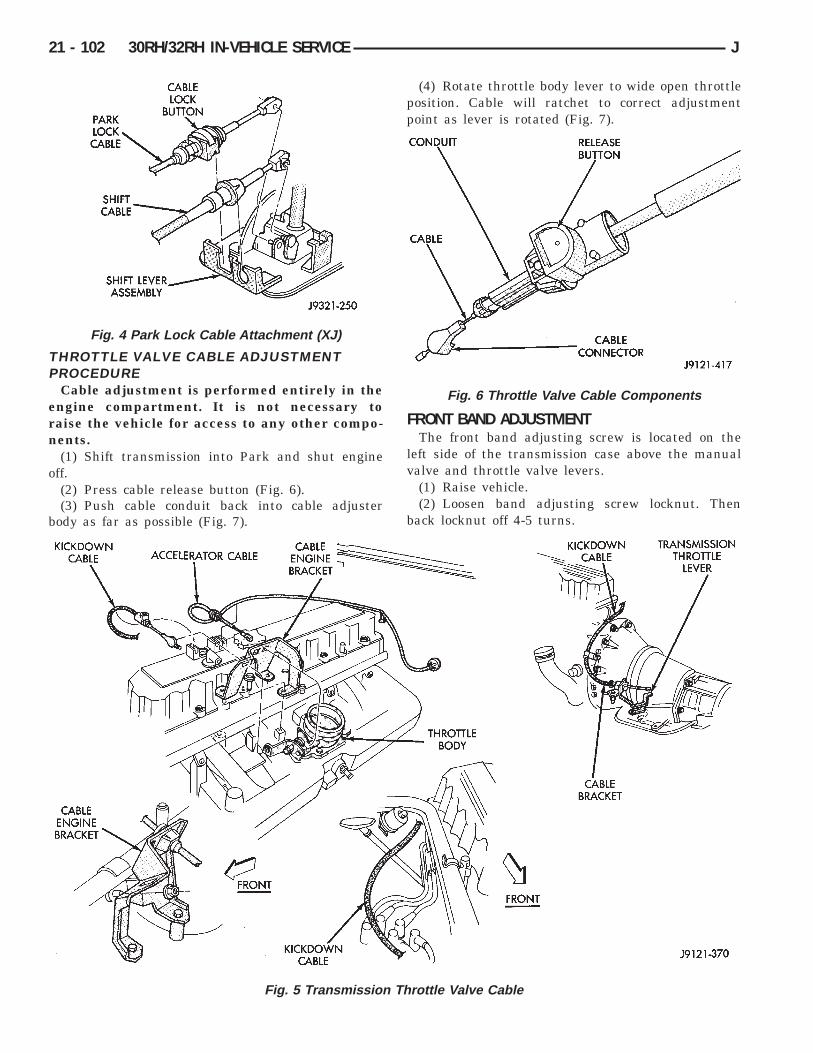
THROTTLE VALVE CABLE ADJUSTMENTPROCEDURE
Cable adjustment is performed entirely in theengine compartment. It is not necessary toraise the vehicle for access to any other compo-nents.
(1) Shift transmission into Park and shut engineoff.
(2) Press cable release button (Fig. 6).(3) Push cable conduit back into cable adjuster
body as far as possible (Fig. 7).
(4) Rotate throttle body lever to wide open throttleposition. Cable will ratchet to correct adjustmentpoint as lever is rotated (Fig. 7).
FRONT BAND ADJUSTMENTThe front band adjusting screw is located on the
left side of the transmission case above the manualvalve and throttle valve levers.
(1) Raise vehicle.(2) Loosen band adjusting screw locknut. Then
back locknut off 4-5 turns.
Fig. 5 Transmission Throttle Valve Cable
Fig. 4 Park Lock Cable Attachment (XJ)
Fig. 6 Throttle Valve Cable Components
21 - 102 30RH/32RH IN-VEHICLE SERVICE J

(3) Clean adjusting screw threads with Mopar rustpenetrant if necessary. Then lubricate threads withMopar spray lube or petroleum jelly. Be sure screwturns freely in case. This is necessary for accurateadjustment.
(4) Tighten band adjusting screw to 8 Nzm (72 in.lbs.) torque with inch-pound torque wrench. IfAdapter Extension C-3705 is needed in order toreach adjusting screw, tighten screw to only 5-6Nzm (47-50 in. lbs.) torque (Fig. 8).
(5) Back off front band adjusting screw as follows:• On 30RH (2.5L), back adjusting screw off 2-1/2turns• On 32RH (4.0L), back adjusting screw off 2-1/4turns
(6) Hold adjuster screw in position and tightenlocknut to 41 Nzm (30 ft. lbs.) torque.
(7) Lower vehicle.
REAR BAND ADJUSTMENTThe transmission oil pan must be removed for ac-
cess to the rear (low-reverse) band adjusting screw.(1) Raise vehicle.
(2) Remove transmission oil pan and drain fluid.(3) Loosen band adjusting screw locknut 5-6 turns.
Be sure adjusting screw turns freely in lever.(4) Tighten adjusting screw as follows: On 32Rh
transmission, tighten screw to 8 Nzm (72 in. lbs.)torque. On 30RH transmission, tighten adjustingscrew to 5 Nzm (41 in. lbs.) torque (Fig. 9).
(5) Back off rear band adjusting screw as follows:• On 30RH (2.5L), back adjusting screw off 7 turns• On 32RH (4.0L), back adjusting screw off 4 turns
(6) Hold adjusting screw in place and tighten lock-nut to 34 Nzm (25 ft. lbs.) torque.
(7) Position new gasket on oil pan and install panon transmission. Tighten pan bolts to 17 Nzm (150 in.lbs.) torque.
(8) Lower vehicle and refill transmission with rec-ommended fluid.
OIL FILTER REPLACEMENT(1) Raise vehicle.(2) Remove oil pan and drain fluid.(3) Remove filter screws and remove oil filter (Fig.
10).(4) Position new filter on valve body and install fil-
ter screws finger tight.(5) Tighten filter screws to 4 Nzm (35 in. lbs.) with
inch-pound torque wrench.(6) Position new gasket on oil pan and install pan
Fig. 7 Throttle Valve Cable Adjustment
Fig. 8 Front Band Adjustment
Fig. 9 Rear Band Lever And Adjusting ScrewLocation
J 30RH/32RH IN-VEHICLE SERVICE 21 - 103

on transmission. Tighten pan bolts to 17 Nzm (150 in.lbs.) torque.
(7) Lower vehicle.(8) Refill transmission with Mopar ATF Plus.
VALVE BODY REMOVAL(1) Raise vehicle.(2) Remove oil pan and drain fluid.(3) Disconnect gearshift and throttle linkage at
transmission levers.(4) Loosen clamp bolts and remove throttle and
manual valve levers from manual valve shaft.(5) Disconnect park/neutral position switch wires
and remove switch and switch seal.(6) Remove valve body oil filter.(7) Remove valve body attaching screws. Lower
valve body slightly and remove accumulator pistonand spring (Fig. 11). Rotate valve body down andaway from case. Pull it forward to disengage parkrod and remove valve body.
(8) Position valve body on bench or on repair standfor disassembly, cleaning and inspection (Fig. 12).
VALVE BODY SERVICEThe valve body can be disassembled for cleaning
and inspection of the individual components. Valvebody service procedures are detailed in the overhaulsection.
The only serviceable valve body components are:• park lock rod and E-clip• switch valve and spring• pressure adjusting screw bracket• throttle valve lever• manual lever• manual lever shaft seal, washer, E-clip and detentball• fluid filter• converter clutch solenoid
The remaining valve body components are servicedonly as part of a complete valve body assembly.
VALVE BODY INSTALLATION(1) Place valve body manual lever in low (1 posi-
tion) so park lock rod can be installed in sprag.(2) Position park sprag with screwdriver to ease
lock rod installation and engagement.(3) Install new seals on accumulator piston if nec-
essary and install piston in case. A small amount ofpetroleum jelly can be used to hold piston in place.
(4) Lubricate shaft of manual lever and lip of shaftseal with petroleum jelly.
(5) Raise valve body and align park rod with caseopening and park sprag. Then push rod end throughopening and past sprag. Rotate propeller shaft if nec-essary.
(6) Position accumulator spring on transfer plate.
Fig. 10 Oil Filter Screw Locations
Fig. 11 Accumulator Piston And Spring
Fig. 12 Valve Body Assembly
21 - 104 30RH/32RH IN-VEHICLE SERVICE J

(7) Align valve body and seat it on case. Be suremanual lever shaft and accumulator spring are prop-erly seated.
(8) Hold valve body in position and install one ortwo attaching bolts to hold valve body in place.
(9) Install remaining valve body bolts. Tighten allbolts evenly in a diagonal pattern to 12 Nzm (105 in-lbs) torque.
(10) Install new oil filter and tighten filter screwsto 4 Nzm (35 in. lbs.) torque.
(11) Connect converter solenoid wire to case con-nector.
(12) Install manual and throttle levers on throttlelever shaft. Tighten lever clamp screws and check forfree operation. Shaft and levers must operate freelywithout any bind.
(13) Install oil pan and new gasket. Tighten panbolts to 17 Nzm (13 ft. lbs.) torque.
(14) Install seal on neutral switch, install switch incase, and connect switch wires.
(15) Lower vehicle.(16) Fill transmission with Mopar ATF Plus, Type
7176 fluid.(17) Adjust gearshift linkage and throttle valve
(kickdown) cable if necessary.
GOVERNOR AND PARK GEAR SERVICE
GOVERNOR/PARK GEAR REMOVAL(1) Raise vehicle.(2) Mark both propeller shaft yokes for assembly
reference and disconnect propeller shafts at transfercase.
(3) Disconnect speed sensor wires and removespeedometer adapter and sensor.
(4) Position support stand under transmission con-verter housing.
(5) Remove rear crossmember.(6) Disconnect parking brake cable at equalizer
and disconnect exhaust components as necessary.(7) Support transfer case with jack.(8) Remove bolts attaching transfer case to trans-
mission adapter housing and remove transfer case.(9) Remove bolts attaching adapter, or extension
housing to transmission and remove adapter/housing.(10) Loosen but do not remove bolts that attach
governor body to park gear.(11) Rotate transmission output shaft until gover-
nor weight assembly is accessible. Then removeE-clip at this end of governor shaft.
(12) Remove governor valve and shaft from gover-nor body (Fig. 13).
(13) Remove snap rings and washers that retaingovernor body and park gear assembly on outputshaft (Fig. 14).
(14) Remove governor body-park gear assemblyfrom output shaft (Fig. 15).
GOVERNOR BODY/PARK GEAR DISASSEMBLY(1) Remove bolts attaching governor body to park
gear; then separate body from gear.
Fig. 13 Governor Valve And Shaft Removal
Fig. 14 Governor Body/Park Gear Retaining SnapRings And Thrust Washer Position
Fig. 15 Governor Body And Park Gear Removal/Installation
J 30RH/32RH IN-VEHICLE SERVICE 21 - 105

(2) Remove cone shaped filter from park gear (Fig.16).
(3) Remove snap ring and retainer washer that se-cure governor weight assembly in body. Use MillerC-3915 Internal Pliers to remove snap ring (Fig. 17).
(4) Remove governor weight assembly from gover-
nor body bore.(5) On 30RH, disassemble two-stage governor
weight as follows:(a) Position weight assembly on suitable size
socket (Fig. 18).(b) Push inner weight downward with nut driver.
Then remove inner weight snap ring with SnapRing Plier Tool C-3915 (Fig. 18).
(c) Remove inner weight and spring from outerweight.(6) On 32RH, disassemble three-stage governor
weight as follows:(a) Slide inner and intermediate assembly out of
outer weight.
(b) Position intermediate weight on suitable sizesocket (Fig. 19).
(c) Push inner weight downward with nut driver.Then remove inner weight snap ring with SnapRing Plier Tool 6823 (Fig. 19).
(d) Remove inner weight and spring from inter-mediate weight.
Fig. 16 Governor Filter Position
Fig. 17 Governor Weight Retaining Snap Ring AndWasher Removal
Fig. 18 Two-Stage Inner Weight Snap RingRemoval/Installation
Fig. 19 Three-Stage Inner Weight Snap RingRemoval/Installation
21 - 106 30RH/32RH IN-VEHICLE SERVICE J

Governor/Park Gear Cleaning and InspectionThoroughly clean all the governor parts in a suit-
able cleaning solution but do not use any type ofcaustic cleaning agents.
The governor weight components (Fig. 20) and thegovernor valve (Fig. 21), must slide freely in theirbores when clean and dry. Minor surface scratchesand burrs can be smoothed with crocus cloth
The aluminum governor valve and outer weighthave a hard coating on them. Check condition of thiscoating carefully. Do not reuse either part if the coat-ing is damaged.
Inspect the governor weight spring for distortion.Replace the spring, if distorted, collapsed, or broken.
Clean the filter in solvent and dry it with low pres-sure compressed air. Replace the filter, if damaged.Inspect the park gear for chipped or worn gear teethor damaged ring grooves. Replace the gear, if dam-aged.
Check the teeth on the park gear for wear or dam-age. Replace the gear if necessary. Inspect the metalseal rings on the park gear hub. Replace the ringsonly if severely worn, or broken.
GOVERNOR/PARK GEAR ASSEMBLY ANDINSTALLATION
(1) Lubricate governor components with transmis-sion fluid during assembly.
(2) Install new seal rings on park gear hub. Installring with interlock ends first and ring with plainends last. Slip each ring on hub and seat them ingrooves. Verify that rear ring ends are securely inter-locked before proceeding.
CAUTION: Exercise care when installing the rings.They are easily broken if overspread or twisted dur-ing installation.
(3) Insert filter screen in park gear. Note that gearhas one filter bore that is concentric and one thathas a notch in it. Filter goes in bore that is concen-tric as shown (Fig. 16).
(4) Position governor body on park gear. Be surefilter is properly aligned in body recess.
(5) Install governor body bolts. Do not fully tightenbolts at this time.
(6) Assemble governor weight components (Fig.20). Then install weight assembly in governor body.Be sure inner weight snap ring is fully seatedbefore proceeding.
(7) Install retainer washer and snap ring that se-cure governor weight assembly in governor body.
(8) Align and install park gear/governor assemblyon output shaft. Be sure hole in output shaft forgovernor valve shaft is aligned with governorvalve bore in governor body. Valve shaft will
Fig. 20 Governor Weight Components (2 and 3-Stage)
J 30RH/32RH IN-VEHICLE SERVICE 21 - 107

bind if misalignment occurs. Remove and repo-sition governor body if necessary.
(9) Verify that shaft bore in governor body and out-put shaft are aligned.
(10) Verify that governor valve will be indexedwith spotface in output shaft. Reposition valve, shaftand body if necessary.
(11) Install an E-clip on one end of governor valveshaft. Be sure rounded side of E-clip is facing out(away from weight).
(12) Insert governor valve shaft through governorweight. Be sure shaft slides freely in bore.
(13) Install governor valve on shaft and in gover-nor body bore.
(14) Install remaining E-clip on governor valveshaft. Be sure rounded side of E-clip is facing out(away from valve).
(15) Install governor body-park gear snap ringsand washer on output shaft as follows:
(a) On models with single snap ring, install snapring. Be sure ring is seated in shaft.
(b) On models with thrust washer and two snaprings, install thin snap ring first. Then installthrust washer second, and thick snap ring last(Fig. 14).
16(c) Verify correct position of snap rings. Besure flat side of each snap ring is toward gov-ernor body.
(16) Tighten governor body-to-park gear bolts to 11Nzm (95 in. lbs.).
(17) Install extension housing/adapter and gasketon transmission. Tighten housing/adapter bolts to 32Nzm (24 ft. lbs.).
(18) Install transfer case and rear crossmember.(19) Install speed sensor and speedometer compo-
nents and connect speed sensor wires.(20) Connect exhaust components and brake cable,
if removed.(21) Align and connect propeller shafts. Tighten
clamp bolts to 19 Nzm (14 ft. lbs.) torque.(22) Remove supports and lower vehicle.(23) Check and adjust transmission fluid level.
PARK LOCK COMPONENT REPLACEMENT
COMPONENT REMOVAL(1) Raise vehicle and remove transfer case and
adapter housing from transmission.(2) Slide sprag shaft out of adapter housing and re-
move park sprag and spring (Fig. 22).(3) Remove snap ring and slide plug and pin as-
sembly out of housing (Fig. 22).(4) If park rod must be serviced, remove valve
body and remove rod.
Fig. 21 Governor Components (30RH/32RH)
21 - 108 30RH/32RH IN-VEHICLE SERVICE J

InspectionCheck the sprag shaft for scores and for free move-
ment in the housing and sprag.Check the sprag and control rod springs for loss of
tension or distortion. Check the square lug on thesprag for broken edges. Check the lugs on the gover-nor support (park gear) for broken edges. Replaceany park lock components that are worn or damaged.
Check the knob on the end of the control rod fornicks, burrs and free turning. Replace the rod if theknob is grooved, or worn, or if the rod is bent. Thepark lock rods used in Chrysler 3-speed transmis-sions are different lengths. If the rod must be re-placed, be sure to install the correct length andshape rod.
COMPONENT INSTALLATION(1) Install park lock rod on valve body.(2) Install reaction plug and pin assembly in the
housing and install the snap ring.(3) Position sprag and spring in housing and in-
stall sprag shaft. Be sure square lug on sprag is fac-ing park gear and that spring is positioned so itmoves sprag away from park gear.
(4) Install valve body.(5) Install adapter housing and transfer case.
PARK/NEUTRAL POSITION SWITCH SERVICEThe starter feed circuit of the switch is through the
switch center terminal (Fig. 23). It provides a groundfor the starter solenoid circuit through the gearshiftlever in park and neutral only.
The two outer terminals of the park/neutral posi-tion switch are for the backup lamp switch circuit.
SWITCH TEST PROCEDURE(1) Remove wiring connector from switch.(2) Test continuity between switch center terminal
and transmission case. Continuity should exist only
when transmission is in Park or Neutral. Replaceswitch if continuity occurs in any gear other thanPark or Neutral.
(3) Shift into reverse and test continuity betweentwo outside terminals on switch. Continuity shouldexist only when transmission is in reverse.
(4) Leave transmission in reverse and test continu-ity between each switch outer terminal and transmis-sion case. Continuity should not exist between eitherpin and case in reverse.
(5) If switch tests OK, check gearshift linkage ad-justment or backup light circuit. Replace switch if itfails continuity tests.
SWITCH REPLACEMENT(1) Position drain pan under neutral switch.(2) Disconnect switch wires.(3) Remove switch from transmission.(4) Move shift lever to Park and Neutral positions.
Inspect manual lever fingers, lever and shaft forproper alignment with switch opening in case. Re-place lever if worn or bent. Do not attempt tostraighten the lever.
(5) Install new switch and seal in case. Tightenswitch to 33 Nzm (24 ft. lbs.) torque.
(6) Adjust transmission fluid level as required.(7) Verify switch operation.
SPEEDOMETER SERVICERear axle gear ratio and tire size determine speed-
ometer pinion requirements. If the pinion must be re-placed, refer to the parts catalogue information forthe correct part. It is important for speedometer ac-curacy that the pinion have the correct number ofteeth.
The speedometer assembly used in XJ models isthe new unit type (one-piece) speed sensor (Fig. 24).However, YJ models may be equipped with either thenew unit style, or the older style that has a two-piece
Fig. 22 Park Lock Components Fig. 23 Park/Neutral Position Switch And ManualLever
J 30RH/32RH IN-VEHICLE SERVICE 21 - 109

speed sensor and metal adapter (Fig. 25). Serviceprocedures for both styles are described in the follow-ing procedures.
SPEEDOMETER ASSEMBLY REMOVAL (WITHUNIT STYLE SENSOR)
(1) Raise vehicle.(2) Disconnect wires from vehicle speed sensor.(3) Remove adapter clamp and screw (Fig. 24).(4) Remove speed sensor and speedometer adapter
as assembly.(5) Remove speed sensor retaining screw and re-
move sensor from adapter.(6) Remove speedometer pinion from adapter.(7) Inspect sensor and adapter O-rings (Fig. 24).
Remove and discard O-rings if worn or damaged.(8) Inspect terminal pins in vehicle speed sensor.
Clean pins with Mopar electrical spray cleaner ifdirty or oxidized. Replace sensor if faulty, or pins areloose, severely corroded, or damaged.
SPEEDOMETER INSTALLATION ANDINDEXING (UNIT STYLE)
(1) Thoroughly clean adapter flange and adaptermounting surface in housing. Surfaces must be cleanfor proper adapter alignment and speedometer oper-ation.
(2) Install new O-rings on speed sensor and speed-ometer adapter if necessary (Fig. 25).
(3) Lubricate sensor and adapter O-rings withtransmission fluid.
(4) Install vehicle speed sensor in speedometeradapter. Tighten sensor attaching screw to 2-3 Nzm(15-27 in. lbs.) torque.
(5) Install speedometer pinion in adapter.(6) Count number of teeth on speedometer pinion.
Do this before installing assembly in housing. Thenlubricate pinion teeth with transmission fluid.
(7) Note index numbers on adapter body (Fig. 25).These numbers will correspond to number of teeth onpinion.
(8) Install speedometer assembly in housing.(9) Rotate adapter until required range numbers
are at 6 o-clock position. Be sure range indexnumbers correspond to number of teeth on pin-ion gear.
(10) Install speedometer adapter clamp and retain-ing screw. Tighten clamp screw to 10-12 Nzm (90-110in. lbs.) torque.
(11) Connect wires to vehicle speed sensor.(12) Lower vehicle and top off transmission fluid
level if necessary.
SPEEDOMETER COMPONENT REMOVAL(TWO-PIECE SENSOR)
(1) Raise vehicle.(2) Disconnect speed sensor wires.(3) Remove bolt attaching vehicle speed sensor to
sensor adapter. Then slide sensor out of adapter.(4) Inspect speed sensor mounting area in sensor
adapter. If transmission fluid is found in this area,oil seal in metal speedometer adapter is leaking andwill have to be replaced.
(5) Remove speedometer adapter clamp bolt andremove clamp (Fig. 26).
(6) Remove speedometer adapter, sensor adapterand speedometer pinion as assembly.
Fig. 24 Speedometer Components (With Unit Style Sensor)
21 - 110 30RH/32RH IN-VEHICLE SERVICE J

SPEEDOMETER COMPONENT INSTALLATIONAND INDEXING (TWO-PIECE SENSOR)
(1) Replace speedometer O-ring if cut, torn, orworn.
(2) If oil seal in metal speedometer adapter needsreplacement, remove old seal with pointed tool. Theninstall new seal with Special Tool C-4004. Push sealinto place with tool until tool bottoms (Fig. 27).
(3) Clean speedometer adapter mounting surface oftransmission, or transfer case thoroughly.
(4) Lubricate adapter seals with transmissionfluid.
(5) Count number of teeth on speedometer pinion.Do this before installing pinion and adapter.
(6) Note range numbers on face of speedometeradapter (Fig. 27). These numbers correspond to num-ber of teeth on speedometer pinion.
(7) Install pinion in adapter and install assembledpinion and adapter in transmission or transfer case.
(8) Rotate speedometer adapter until requiredrange numbers are at 6 o’clock position (Fig. 28).Verify that range numbers correspond to num-ber of teeth on pinion.
(9) Push speedometer adapter into place untilseated.
(10) Install speedometer adapter clamp and bolt.Tighten bolt to 11 Nzm (100 in. lbs.) torque.
(11) Install sensor adapter on speedometeradapter. Tighten sensor adapter coupling nut to 17Nzm (150 in. lbs.) torque.
(12) Carefully align and insert vehicle speed sensorinto sensor adapter.
(13) Install bolt that attaches speed sensor toadapter. Tighten bolt to 5-8 Nzm (48-72 in. lbs.)
(14) Connect wires to speed sensor.(15) Lower vehicle.(16) Check top off transmission fluid level if neces-
sary.
TRANSMISSION COOLER LINE AND FITTINGSERVICE
The transmission cooler lines are attached withquick connect fittings. Two types of fitting will beused.
Fig. 25 Location Of Index Numbers On SpeedometerAdapter (Unit Style Sensor)
Fig. 26 Speedometer Components (With Two-PieceSensor)
Fig. 27 Installing Speedometer Adapter Seal (WithTwo-Piece Sensor And Metal Adapter)
Fig. 28 Indexing Speedometer Adapter (WithTwo-Piece Sensor)
J 30RH/32RH IN-VEHICLE SERVICE 21 - 111

Early production models will have the type 2 fit-ting used previously. This fitting requires a releasetool to disconnect the cooler line from the fitting (Fig.29). Later production models will have a new stylefitting that does not require any type of release tool.This fitting has a plastic insert with built-in releasetabs (Fig. 30).
Cooler Line And Fitting ServiceThe cooler lines and fittings are only serviceable as
assemblies. Damaged fittings or cooler lines are to bereplaced. Fittings swedged into cooler line hoses (Fig.31) are serviced only as part of the entire cooler hose.
DISCONNECTING COOLER LINES WITH TYPE2 FITTING
(1) If fitting and cooler line are encrusted withdirt, mud, or grease, clean fitting and cooler line withMopar spray type carburetor or brake cleaner. Plasticrelease tool will not fit into retainer clip if fitting isfull of foreign material.
(2) Slide small plastic release tool into fitting untiltool bottoms against cooler line flange (Fig. 29).
(3) Push and turn release tool to spread retainerclip and pull cooler line out of fitting (Fig. 29).
(4) Cover open ends of cooler lines and fittings toprevent dirt entry.
(5) Inspect condition of fitting. Replace transmis-sion fitting as an assembly if fitting body or retainer
clip is damaged. Replace cooler line as assembly, iffitting swedged into cooler line hose, is damaged.
DISCONNECTING COOLER LINES WITH NEWSTYLE FITTING
The new style fitting does not require any kind ofrelease tool. The fitting inserts have built-in releasetabs that only require finger pressure to releasethem.
The new style fitting insert is unique. The insertdoes not stay in place inside the fitting when re-leased. Instead, the insert remains on the line anddoes not have to be removed.
To release a new style fitting, simply squeeze theinsert tabs (Fig. 32) and disconnect the line. The in-sert will remain in place on the line, or fitting anddoes not have to be removed (Fig. 33).
Fig. 30 New Style Quick Connect Fitting With Insert
Fig. 29 Disconnecting Cooler Line With ReleaseTool (Type 2 fitting)
Fig. 31 Cooler Line Fitting Placement
Fig. 32 Releasing Cooler Line From New StyleFitting
21 - 112 30RH/32RH IN-VEHICLE SERVICE J

CONNECTING COOLER LINES AND FITTINGS(ALL TYPES)
(1) Wipe cooler line and fitting clean with shoptowel.
(2) Insert cooler line into fitting. Then push lineinward until retainer or insert secures line. A snap orclick sound will be heard when the insert tabs or re-tainer clip seats behind the cooler line flange.
(3) Pull outward on cooler lines/fittings toverify they are properly secured.
CAUTION: The wire retainer clips or insert releasetabs secure the cooler lines. If the clips or tabs aredeformed, distorted, or not fully seated, normalfluid pressure could unseat the lines resulting influid loss and transmission damage. Be very surethe cooler lines are firmly secured as described instep (3).
CONVERTER DRAINBACK CHECK VALVE SERVICEThe converter drainback check valve is located in
the cooler outlet (pressure) line near the radiatorlower tank. The valve prevents fluid drainback whenthe vehicle is parked for lengthy periods. The valvecheck ball is spring loaded and has an opening pres-sure of approximately 2 psi. Refer to the cooler flowtest procedure for valve testing.
The valve is serviced as an assembly; it is not re-pairable. Do not clean the valve if restricted, or con-taminated by sludge, or debris. If the valve fails, or ifa transmission malfunction occurs that generatessludge and/or clutch particles and metal shavings,the valve must be replaced.
The valve must be removed whenever the coolerand lines are reverse flushed. The valve can be flowtested when necessary. The procedure is exactly thesame as for flow testing a cooler.
If the valve is restricted, installed backwards, or inthe wrong line, it will cause an overheat conditionand possible transmission failure.
CAUTION: The drainback valve is a one-way valve.As such, it must be properly oriented in terms offlow direction. In addition, the valve must only be
installed in the pressure line. Otherwise flow will beblocked causing overheat and eventual transmis-sion failure.
TRANSMISSION COOLER FLOW TESTINGThe transmission main and auxiliary coolers, plus
the drainback valve, should be flow tested wheneverfluid overheating is noted.
Restricted flow caused by contamination, or acooler malfunction, reduces lubrication fluid flowthroughout the transmission. This can result in fluidoverheating, fluid breakdown, bushing wear, shiftproblems and component failure.
Normal color of transmission fluid varies frombright red, to light pink. Fluid overheating is indi-cated when fluid color ranges from orange-brown toblack, and the fluid smells burned, or containssludge.
CAUTION: If a transmission malfunction contami-nates the fluid with clutch disc and metal particles,the cooler and lines must be reverse flushed thor-oughly. Flushing will prevent sludge and particlesfrom flowing back into the transmission and con-verter after repair.
Cooler flow is tested by measuring the amount offluid pumped through the cooler in a specified timeby the transmission oil pump. The same flow testprocedure is used for the drainback valve, maincooler, and auxiliary cooler.
Cooler And Drainback Valve Flow Test Procedure(1) Test flow through drainback valve as follows:
(a) Add extra quart of ATF Plus to transmission.(b) Disconnect pressure line at radiator fitting, or
at drainback valve and position hose or valve endin one quart test container.
(c) Shift transmission into neutral, run engine atidle speed for 20 seconds, and note flow from valve.Use stopwatch to check test time.
(d) Replace drainback valve if flow is less thanone quart in 20 seconds, is intermittent, or doesnot flow at all.
(e) Connect pressure hose to radiator fitting andproceed to cooler flow test.(2) Test flow through main cooler as follows:
(a) Disconnect cooler return (rear) line at trans-mission and place it in one quart test container.
(b) Add extra quart of fluid to transmission.(c) Shift transmission into neutral, run engine at
idle speed for 20 seconds, and note flow from valve.Use stopwatch to check test time.
(d) Replace cooler if fluid flow is less than onequart in 20 seconds, is intermittent, or does notflow at all.
Fig. 33 New Style Fitting Insert (On Cooler Line)
J 30RH/32RH IN-VEHICLE SERVICE 21 - 113

(3) If vehicle is equipped with auxiliary cooler,test cooler flow as described in step (2).
TRANSMISSION COOLER REVERSE FLUSHINGThe flushing procedure applies to standard and
auxiliary coolers alike. Although pressure equipmentis preferred, reverse flushing can be performed withhand operated equipment as follows.
(1) Disconnect cooler pressure and return lines attransmission (Figs. 34 and 35).
(2) Remove and discard drainback valve. Installfabricated hose and fitting in place of valve.
(3) Position drain pan under cooler pressure line tocatch material flushed through cooler and lines.
(4) Reverse flush cooler using hand operated suc-tion gun filled with mineral spirits. Insert gun nozzle(or hose) into cooler return line. Then force mineralspirits into line and through cooler.
(5) Continue reverse flushing until fluid comingout of cooler pressure line is clear. Replace cooler iffluid cannot be pumped through.
(6) Clear flushing materials from cooler and lineswith short pulses of compressed air. Insert air gunnozzle into cooler return line and continue short airpulses until all fluid is cleared from cooler and lines.
(7) Pump one quart of fresh automatic transmis-sion fluid through cooler and lines before reconnect-ing lines.
(8) Install new drainback valve in pressure line.(9) Check and adjust transmission fluid level as
described in this section.
Fig. 34 Cooler Line Fitting Identification (30RH/32RH)
Fig. 35 Cooler Line Routing (YJ)
21 - 114 30RH/32RH IN-VEHICLE SERVICE J

30RH/32RH TRANSMISSION REMOVAL AND INSTALLATION
INDEX
page page
Converter—Pump Seal—Drive Plate Service . . . . 116Transmission and Converter Installation . . . . . . . . 117
Transmission and Converter Removal . . . . . . . . . 115
TRANSMISSION AND CONVERTER REMOVAL(1) Remove fan shroud attaching bolts.(2) Disconnect transmission fill tube at upper
bracket.(3) Raise vehicle.(4) Remove inspection cover from converter hous-
ing and remove skid plate for access, if necessary.(5) Remove transmission fill tube and fill tube O-
ring.(6) Remove starter motor.(7) Mark propeller shafts and axle yokes for align-
ment reference.(8) Disconnect propeller shafts at yokes. Secure
shafts to frame rails with wire.(9) Disconnect exhaust pipes at exhaust manifolds,
if necessary.(10) Drain transfer case lubricant, if transfer case
will also be serviced.(11) Disconnect vehicle speed sensor wires.(12) Disconnect transfer case shift linkage.(13) Disconnect gearshift cable/linkage and throttle
valve cable at transmission levers.(14) Disconnect transfer case vent hose. Then dis-
connect indicator switch wires on XJ, or vacuumswitch harness on YJ.
(15) Remove wire harness from clips on transfercase.
(16) Remove transfer case attaching nuts and re-move transfer case. Use transmission jack or helperto support and remove transfer case.
(17) Disconnect park/neutral position switch wires.(18) Disconnect and remove crankshaft position
sensor (Figs. 1 and 2). Retain sensor bolt (or bolts)for reinstallation.
CAUTION: The crankshaft position sensor can bedamaged during transmission removal (or installa-tion) if the sensor is still bolted to the engine block.To avoid damage, remove the sensor before remov-ing the transmission.
(19) Remove wire harnesses from clips/tie strapson transmission.
(20) Remove converter housing access cover andmark drive plate and converter for alignment refer-ence.
(21) Remove bolts attaching converter to driveplate.
(22) Support engine with support stand.(23) Support transmission with transmission jack.
Secure transmission to jack with safety chain.
Fig. 1 Crankshaft Position Sensor (2.5L)
Fig. 2 Crankshaft Position Sensor (4.0L YJ)
J 30RH/32RH TRANSMISSION REMOVAL AND INSTALLATION 21 - 115

(24) Remove bolts/nuts attaching cushion andtorque arm bracket to skid plate (Fig. 3).
(25) Remove skid plate, or rear crossmember, ifequipped.
(26) Lower transmission slightly and disconnectcooler lines at transmission.
(27) Remove bolts attaching transmission con-verter housing to engine block.
(28) Move transmission and converter rearwarduntil clear of crankshaft.
(29) Hold converter in position and lower transmis-sion until converter housing clears engine.
(30) Remove converter from transmission.(31) Following components can now be serviced if
necessary:• torque converter• torque converter drive plate• oil pump seal• engine rear core hole plugs• engine rear oil galley plugs
CONVERTER—PUMP SEAL—DRIVE PLATESERVICE
Drive PlateThe drive plate can be replaced or removed for ser-
vice access after the transmission is out of the vehi-cle (Fig. 4).
CAUTION: On YJ models with a 2.5L engine and30RH transmission, special bolts are used to attachthe driveplate to the crankshaft. These bolts have asmaller hex head for torque converter clearance.DO NOT interchange these bolts with similar sizebolts for any reason.
Torque ConverterThe torque converter and driveplate are accessible
for service after the transmission has been removed(Fig. 4).
The torque converter is not a serviceable part. Ifthe converter is contaminated or damaged in anyway, it must be replaced as an assembly. Do not at-tempt to flush a converter contaminated bymetal or clutch facing particles. Flushing willnot remove these contaminants.
The driveplate is also not serviceable. The drive-plate should be replaced if damaged in any way.
On converters or driveplates with a starter ringgear, the ring gear is not replaceable. It will be nec-essary to replace the converter, or driveplate as anassembly if the gear teeth are damaged.
Oil Pump Seal ServiceThe oil pump seal is accessible and can be replaced
after the transmission and torque converter are re-moved.
Use Special Tool C-3981-B to remove the seal (Fig.5). To use the tool, first start the tool into the seal byhand. Next, thread the tool into the seal as far as itwill go. Use a wrench on the tool hex to turn the tool.Continue tightening until all the tool threads firmly
Fig. 3 Transmission Rear Mount
Fig. 4 Typical Converter And Drive Plate
21 - 116 30RH/32RH TRANSMISSION REMOVAL AND INSTALLATION J

grip the metal part of the seal. Then tighten the toolpuller screw to withdraw the seal from the pumpbody.
Use Special Tool C-4193-A to install the seal (Fig.6). Be sure to lubricate the pump seal and converterhub with transmission fluid before installation.
TRANSMISSION AND CONVERTER INSTALLATION
CAUTION: If the transmission was repaired to cor-rect a problem that generated sludge and debris,the fluid cooler and lines must be reverse flushedand the torque converter and drainback valve re-placed. Sludge and metal or friction particles mustbe removed from the cooler system before reinstall-ing the transmission. This avoids re-contaminatingthe repaired transmission. Failure to flush the sys-tem will result in repeat failure and a shop come-back.
(1) Lubricate converter drive hub and pump sealwith Mopar ATF Plus transmission fluid. Then in-stall converter. Turn converter back and forth to
align drive slots in converter hub with pump gearlugs. Be sure converter is fully seated in pump (Fig.7).
(2) Temporarily secure converter with C-clamp ormetal strap attached across converter housing.
(3) Position transmission on jack and secure itwith safety chains.
(4) Raise transmission and align converter withdrive plate.
(5) Move transmission forward. Then raise, loweror tilt transmission to align converter housing withengine block dowels.
(6) Install two transmission attaching bolts.Tighten bolts just enough to hold transmission con-verter housing in place on block.
(7) Install torque converter attaching bolts.Tighten bolts to following torque.• 54 Nzm (40 ft. lbs.) with 9.5 in. 3-lug converter• 74 Nzm (55 ft. lbs.) with 9.5 in. 4-lug converter• 74 Nzm (55 ft. lbs.) with 10.0 in. 4-lug converter• 31 Nzm (270 in. lbs.) with 10.75 in. 4-lug converter
(8) Install and tighten remaining bolts that attachtransmission converter housing to engine block (Fig.8).
CAUTION: Be sure the converter housing is fullyseated on the engine block dowels before tighten-ing any bolts.
(9) Install crankshaft position sensor.(10) Install transmission fill tube and O-ring (Fig.
5).(11) Connect transmission cooler lines to fittings.
Refer to Figure 9 for cooler line identification.
Fig. 5 Pump Seal Removal
Fig. 6 Pump Seal Installation
Fig. 7 Checking Torque Converter Seating
J 30RH/32RH TRANSMISSION REMOVAL AND INSTALLATION 21 - 117

(12) Install transfer case on transmission. Tightenattaching nuts to 47 Nzm (35 ft. lbs.) torque if casehas 3/8 studs, or 35 Nzm (26 ft. lbs.) if case has 5/16studs.
(13) Install rear crossmember and attach transmis-sion rear support to crossmember.
(14) Remove transmission jack.(15) Connect vehicle speed sensor wires.(16) Install inspection cover on converter housing.
(17) Install exhaust pipes and support brackets, ifremoved.
(18) Install starter motor.(19) Connect wires to park/neutral position switch.(20) Connect gearshift and linkage and throttle ca-
ble.(21) Connect transfer case shift linkage.(22) Connect propeller shafts to transfer case
yokes.(23) Connect front exhaust pipes and catalytic con-
verter support bracket bolts (if removed).(24) Install skid plate, rear cushion and bracket, if
removed.(25) Fill transfer case to bottom edge of fill plug
hole with Mopar Dexron II.(26) Lower vehicle and fill transmission to correct
level with ATF Plus, type 7176 fluid.(27) Install fan shroud and bolts (if removed).(28) Check and adjust gearshift cable or linkage if
necessary. Then check and adjust throttle valve cableif necessary.
Fig. 8 Transmission Attachment
Fig. 9 Transmission Cooler Line Location AndIdentification
21 - 118 30RH/32RH TRANSMISSION REMOVAL AND INSTALLATION J

30RH/32RH TRANSMISSION OVERHAUL
INDEX
page page
Adapter/Extension Housing Inspection and ParkLock Component Overhaul . . . . . . . . . . . . . . . . 127
Front Clutch Overhaul . . . . . . . . . . . . . . . . . . . . . 134Front Servo and Band Overhaul . . . . . . . . . . . . . 146Governor and Park Gear Overhaul . . . . . . . . . . . 127Oil Pump Overhaul . . . . . . . . . . . . . . . . . . . . . . . 131Overhaul Service Information . . . . . . . . . . . . . . . . 125Overrunning Clutch—Low-Reverse Drum—Rear
Support Overhaul . . . . . . . . . . . . . . . . . . . . . . . 125Planetary Gear Train Overhaul . . . . . . . . . . . . . . 141
Rear Clutch Overhaul . . . . . . . . . . . . . . . . . . . . . 138Rear Servo and Band Overhaul . . . . . . . . . . . . . . 146Transmission Assembly and Adjustment Procedures . 155Transmission Assembly Tips . . . . . . . . . . . . . . . . 155Transmission Case Cleaning and Inspection . . . . 125Transmission Disassembly . . . . . . . . . . . . . . . . . . 119Valve Body Assembly and Adjustment . . . . . . . . . 153Valve Body Disassembly and Inspection . . . . . . . 147
TRANSMISSION DISASSEMBLY(1) Clean transmission exterior with steam gun or
with solvent. Wear eye protection during cleaningprocess.
(2) Remove throttle and shift levers from valvebody manual shaft and throttle lever shaft.
(3) Mount transmission in repair stand C-3750-B(Fig. 1).
(4) Remove nuts attaching adapter, or extensionhousing to transmission case.
(5) Remove adapter/extension housing and gasket(Fig. 2).
(6) Remove rear bearing and snap ring, ifequipped.
(7) Remove park/neutral position switch and seal(Fig. 3).
Fig. 1 Transmission Mounted On Typical RepairStand
Fig. 2 Adapter Housing Removal/Installation (4 x 4Models)
Fig. 3 Park/Neutral Position Switch Removal/Installation
J 30RH/32RH TRANSMISSION OVERHAUL 21 - 119

(8) Remove oil pan bolts and remove pan and gas-ket (Fig. 4).
(9) Remove hex head valve body attaching bolts(Fig. 5).
(10) Disconnect solenoid wire from case connector(Fig. 6).
(11) Lift valve body upward, guide park rod out ofcase opening and remove valve body (Fig. 5).
(12) Remove accumulator spring and piston (Fig.8).
(13) Remove front band pivot pin access plug (Fig.9). Plug is accessible through converter housing. Use1/4 inch drive extension to remove plug as shown.
(14) Loosen front band adjusting screw locknut 4-5turns. Then tighten band adjusting screw until bandis tight around front clutch retainer. This preventsfront/rear clutches from coming out with pump andpossibly damaging clutch or pump components.
Fig. 4 Oil Pan Removal/Installation
Fig. 5 Valve Body Attaching Bolt Locations (Typical)
Fig. 6 Solenoid Wire Connection
Fig. 7 Valve Body Removal/Installation
Fig. 8 Removing/Installing Accumulator Piston AndSpring
Fig. 9 Removing/Installing Front Band Pivot PinAccess Plug
21 - 120 30RH/32RH TRANSMISSION OVERHAUL J

(15) Remove oil pump bolts.(16) Thread bolts in Slide Hammer Tools C-3752
into threaded holes in pump body flange (Fig. 10).(17) Bump slide hammer weights outward to re-
move pump and reaction shaft support assemblyfrom case (Fig. 10).
(18) Loosen front band adjusting screw until bandis completely loose.
(19) Squeeze front band together and remove bandstrut (Fig. 11).
(20) Remove front band reaction pin with pencilmagnet. Pin is accessible from converter housing sideof case (Fig. 12).
(21) Remove front band lever (Fig. 13)(22) Slide front band rearward and onto driving
shell. Band will not be removed until after front/rearclutch removal.
(23) Remove front and rear clutch units as assem-bly. Grasp input shaft, hold clutch units together andremove them from case (Fig. 14).
Fig. 10 Removing Oil Pump/Reaction Shaft Support
Fig. 11 Removing/Installing Front Band Strut
Fig. 12 Removing Front Band Reaction Pin
Fig. 13 Removing/Installing Front Band Lever
Fig. 14 Removing Front/Rear Clutch Assemblies
J 30RH/32RH TRANSMISSION OVERHAUL 21 - 121

(24) Lift front clutch off rear clutch (Fig. 15). Setclutch units aside for disassembly, cleaning and over-haul.
(25) Remove output shaft thrust washer from out-put shaft (or from rear clutch hub).
(26) Remove output shaft thrust plate from outputshaft hub (Fig. 16).
(27) Slide front band off driving shell (Fig. 17) andremove band from case.
(28) Remove E-clip from one end of governor valveshaft and remove valve and shaft from governor body(Fig. 19). Reinstall E-clip on shaft to avoid losing it.
(29) Remove thick snap, thrust washer and thinsnap ring that retain governor body and park gear onshaft (Fig. 19).
(30) Loosen bolts attaching governor body to parkgear.
Fig. 15 Separating Front/Rear Clutch Assemblies
Fig. 16 Removing/Installing Output Shaft ThrustPlate
Fig. 17 Front Band Removal/Installation
Fig. 18 Removing Governor Valve And Shaft
Fig. 19 Governor Body/Park Gear Attachment
21 - 122 30RH/32RH TRANSMISSION OVERHAUL J

(31) Mark position of governor body on park gearwith center punch or scriber.
(32) Remove governor body and park gear as as-sembly (Fig. 20). Work park gear out of rear supportand slide assembly off output shaft.
(33) Remove planetary geartrain as assembly (Fig.21). Support geartrain with both hands during re-moval. Do not allow machined surfaces on outputshaft to become nicked or scratched.
(34) Loosen rear band adjusting screw until bandis fully released and does not grip low reverse drum.
(35) Remove snap ring that secures low-reversedrum to rear support (Fig. 22).
(36) Remove rear band lever pins as follows:(a) On 30RH transmission, rear band has only
one pivot pin. Remove pin with parallel jaw snap
ring pliers (Fig. 23). Spread plier jaws in pin boreto grip pin. Then remove pin with a twist and pullmotion.
(b) On 32RH transmission, rear band has twopins. Remove pivot pin and reaction pin with par-allel jaw snap ring pliers (Fig. 24).(37) Remove rear band lever, link and strut.(38) Mark position of rear support for assembly
reference (Fig. 25). Use scriber or center punch tomark case and support.
(39) Remove rear support bolts and remove sup-port from low-reverse drum and case (Fig. 26). Keeprear support bolts together for assembly reference.
(40) Remove bolts attaching overrunning clutchcam to case (Fig. 27).
(41) Remove low-reverse drum and overrunningclutch as assembly. Slide drum and clutch throughrear band and out of case. Set drum and clutch as-sembly aside for cleaning and inspection.
(42) Remove rear band and link from case.
Fig. 20 Removing/Installing Governor Body AndPark Gear
Fig. 21 Planetary Geartrain Removal
Fig. 22 Removing Low-Reverse Drum Snap Ring
Fig. 23 Removing Rear Band Lever Pivot Pin (30RH)
J 30RH/32RH TRANSMISSION OVERHAUL 21 - 123

(43) Compress front servo rod guide about 3 mm(1/8 in.) with a large C-clamp and tool C-4470, orCompressor Tool C-3422-B (Fig. 28).
(44) Remove front servo rod guide snap ring (Fig.28). Exercise caution when removing snap ring.Servo bore can be scratched or nicked if care isnot exercised.
(45) Remove compressor tools and remove frontservo rod guide, spring and servo piston.
(46) Compress rear servo spring retainer about 1.5mm (1/16 in.) with C-clamp and Tool C-4470 or SP-5560 (Fig. 29). Valve Spring Compressor C-3422-Bcan also be used to compress spring retainer.
Fig. 24 Removing Rear Band Pivot And ReactionPins (32RH)
Fig. 25 Marking Rear Support For AssemblyReference
Fig. 26 Removing Rear Support
Fig. 27 Overrunning Clutch Cam Bolt Locations
Fig. 28 Compressing Front Servo Rod Guide
21 - 124 30RH/32RH TRANSMISSION OVERHAUL J

(47) Remove rear servo spring retainer snap ring.Then remove compressor tools and remove rear servospring and piston.
OVERHAUL SERVICE INFORMATIONInspect the transmission bushings during overhaul.
Bushing condition is important as severely worn, orscored bushings contribute to low pressures, clutchslip and accelerated wear of other components. How-ever, do not replace bushings as a matter ofcourse. Replace bushings only when they areactually worn, or scored.
Use recommended tools to replace bushings. Thetools are sized and designed to remove, install andseat bushings correctly. The bushing replacementtools are included in Bushing Tool Set C-3887-B orC-3887-J. The bushing tools are manufactured byMiller Tool Co. and is available through the dealertool program.
Pre-sized service bushings are available for replace-ment purposes. Only the sun gear bushings are notserviced. Replace the gear as an assembly if thebushings are worn, or scored.
Heli-Coil inserts are recommended for repairingdamaged, stripped or worn threads in aluminumparts. These inserts are available from most automo-tive jobbers. Stainless steel inserts are preferred.
The use of crocus cloth is permissible where neces-sary. When used on valves, use care to avoid round-ing off sharp edges. Sharp edges are vital as theyprevent foreign matter from getting between thevalve and valve bore.
Do not reuse oil seals, gaskets, seal rings, orO-rings during overhaul. Replace these parts as amatter of course. Also do not reuse snap rings or E-clips that are bent or distorted. Replace these partsas well.
Lubricate transmission parts with Mopar ATFPlus, Type 7176 transmission fluid during overhauland assembly.
Use petroleum jelly to hold parts like thrust wash-ers in place during assembly. Use Mopar Door Ease,Ru-Glyde, or similar products to lubricate pistonseals and O-rings to ease installation. Petroleum jellycan also be used to prelubricate parts during reas-sembly if desired.
TRANSMISSION CASE CLEANING ANDINSPECTION
Clean the case in a solvent tank. Flush the casebores and fluid passages thoroughly with solvent.Use compressed air to dry the case and clear thefluid passages. Be sure all solvent is removed fromthe case as well.
Do not use shop towels or rags to dry the case(or any other transmission component) unlessthey are made from lint-free materials. Lintwill readily adhere to case surfaces and trans-mission components and will circulate through-out the transmission after assembly. A sufficientquantity of lint can block fluid passages and in-terfere with valve body operation.
Inspect the case for cracks, porous spots, wornbores, or damaged threads. Damaged threads can berepaired with Helicoil thread inserts. However, thecase will have to be replaced if it exhibits any type ofdamage or wear.
Lubricate the front band adjusting screw threadswith petroleum jelly and thread the screw part-wayinto the case. Be sure the screw turns freely.
Remount the case in a repair stand after cleaningand inspection.
OVERRUNNING CLUTCH—LOW-REVERSEDRUM—REAR SUPPORT OVERHAUL
DISASSEMBLING OVERRUNNING CLUTCH/LOW-REVERSE DRUM
If the clutch assembly came out with the low-re-verse drum, thread two clutch cam bolts into thecam. Then lift the cam out of the drum with the bolts(Fig. 30). Rotate the cam back and forth to ease re-moval if necessary. Remove the clutch roller andspring assembly from the race afterward.
CLEANING AND INSPECTIONClean the overrunning clutch assembly, clutch cam,
low-reverse drum and rear support in solvent. Drythem with compressed air after cleaning.
Inspect condition of each clutch part after cleaning.Replace the overrunning clutch roller and spring as-sembly if any rollers or springs are worn or damaged,or if the roller cage is distorted, or damaged. Replacethe cam if worn, cracked or damaged.
Fig. 29 Compressing Rear Servo Spring
J 30RH/32RH TRANSMISSION OVERHAUL 21 - 125

Replace the low-reverse drum if the clutch race,roller surface or inside diameter is scored, worn ordamaged. Do not remove the clutch race fromthe low-reverse drum under any circumstances.Replace the drum and race as an assembly if ei-ther component is damaged.
Examine the rear support carefully for wear,cracks, scoring or other damage. Be sure the supporthub is a snug fit in the case and drum. Replace thesupport if worn or damaged.
ASSEMBLING OVERRUNNING CLUTCH/LOW-REVERSE DRUM
(1) Assemble clutch rollers and springs in retainerif necessary (Fig. 31).
(2) Install overrunning clutch roller, spring and re-tainer assembly in clutch cam (Fig. 32).
(3) Temporarily assemble and check overrunningclutch operation as follows:
(a) Assemble cam and clutch.
(b) Install clutch assembly on low-reverse drumwith twisting motion (Fig. 33).
(c) Install drum-clutch assembly in case and in-stall clutch cam bolts.
(d) Install rear support and support attachingbolts.
(e) Check low-reverse drum rotation. Drumshould rotate freely in clockwise directionand lock when turned in counterclockwise di-rection (as viewed from front of case).
(4) Note component position for assembly refer-ence. Bolt holes in clutch cam are countersunk onone side, Be sure this side of cam will face rearwardwhen installed (Fig. 34).
Fig. 30 Removing Overrunning Clutch FromLow-Reverse Drum
Fig. 31 Overrunning Clutch Rollers, Springs,Retainer
Fig. 32 Assembling Overrunning Clutch And Cam
Fig. 33 Temporary Assembly Of Clutch And DrumTo Check Operation
21 - 126 30RH/32RH TRANSMISSION OVERHAUL J

(5) Remove rear support, overrunning clutch andlow-reverse drum. Set components aside for final as-sembly. If overrunning clutch will be installedbefore final assembly, install cam only as de-scribed in Transmission Assembly And Adjust-ment section. Clutch cam must be properlyindexed in case to fit and operate properly.
ADAPTER/EXTENSION HOUSING INSPECTION ANDPARK LOCK COMPONENT OVERHAUL
Clean the housing and park lock components in sol-vent and dry them with compressed air.
Inspect the output shaft bearing in the housing(Fig. 35). Replace the bearing if worn, damaged, ornoisy.
Examine the park lock components. If replacementis necessary, remove the shaft with parallel jaw snapring pliers (Fig. 36) and remove the sprag andspring. Then remove the spring clip and reactionplug (Fig. 37).
Compress the reaction plug spring clip onlyenough to remove or install it. The clip is easilydistorted if overcompressed. Replace the clip ifit becomes bent or distorted. Do not straightenand reuse the clip if this occurs.
Be sure a replacement sprag is installed so thesprag locking lug will face the park gear. Also be surethe spring is correctly positioned as shown (Fig. 38).The sprag may not retract if the spring is im-properly installed.
GOVERNOR AND PARK GEAR OVERHAUL
GOVERNOR/PARK GEAR DISASSEMBLY(1) Remove bolts attaching governor body to park
gear; then separate body from gear.(2) Remove cone shaped filter from park gear (Fig.
39).(3) Remove snap ring and retainer washer that se-
cure governor weight assembly in body. Use MillerC-3915 Internal Pliers to remove snap ring (Fig. 40).
(4) Remove governor weight assembly from gover-nor body bore.
(5) On 30RH, disassemble two-stage governorweight as follows:
(a) Position weight assembly on suitable sizesocket (Fig. 41).
Fig. 34 Assembled Overrunning Clutch Components
Fig. 35 Adapter Housing Bearing ( 4 x 4 Models)
Fig. 36 Park Sprag, Shaft And Spring Removal
J 30RH/32RH TRANSMISSION OVERHAUL 21 - 127

(b) Push inner weight downward with nut driverand remove inner weight snap ring. Use Miller In-ternal Snap Ring Pliers C-3915 to remove ring(Fig. 41).
(c) Remove inner weight and spring from outerweight.(6) On 32RH, disassemble three-stage governor
weight as follows:(a) Position intermediate weight on suitable size
socket (Fig. 42).
(b) Push inner weight downward with nut driver.Then remove inner weight snap ring with SnapRing Plier Tool 6823 (Fig. 42).
(c) Remove inner weight and spring from inter-mediate weight.
CLEANING AND INSPECTIONThoroughly clean all the governor parts in a suit-
able cleaning solution but do not use any type ofcaustic cleaning agents.
Examine the governor components carefully. Dis-card any snap rings or E-clips if distorted, or worn.Be sure the governor weights operate freely in thebores and do not bind. Also verify that the governorvalve slides freely on the shaft and in the bore.
The governor weight components (Fig. 43), and thegovernor valve (Fig. 44), must slide freely in theirbores when clean and dry. Minor surface scratchesand burrs can be smoothed with crocus cloth
Fig. 37 Park Sprag Reaction Plug And SpringLocation
Fig. 38 Correct Position Of Sprag And Spring
Fig. 39 Governor Filter Position
Fig. 40 Governor Weight Retaining Snap Ring AndWasher Removal
21 - 128 30RH/32RH TRANSMISSION OVERHAUL J

The aluminum governor valve and outer weighthave a hard coating on them. Check condition of thiscoating carefully. Do not reuse either part if the coat-ing is damaged.
Inspect the governor weight spring for distortion.Replace the spring, if distorted, collapsed, or broken.
Clean the filter in solvent. Shake excess solventfrom filter and allow it to air dry. Replace the filter,
Fig. 41 Two-Stage Inner Weight Snap RingRemoval/Installation
Fig. 42 Three-Stage Inner Weight Snap RingRemoval/Installation
Fig. 43 Governor Weight Components (2- and 3-Stage)
J 30RH/32RH TRANSMISSION OVERHAUL 21 - 129

if damaged. Inspect the park gear for chipped orworn gear teeth or damaged ring grooves. Replacethe gear, if damaged.
Check the teeth on the park gear for wear or dam-age. Replace the gear if necessary. Inspect the metalseal rings on the park gear hub. Replace the ringsonly if severely worn, or broken.
Minor scratches, or burrs on governor componentscan be cleaned up with oil-soaked crocus cloth. How-ever, do not attempt to salvage components that areseverely worn or scored.
The governor valve is made of aluminum andthe output shaft has been spotfaced to acceptthe valve. The aluminum valve must not beused in prior transmissions. The valve can onlybe used with an output shaft that has beenspotfaced for valve end clearance. In addition,the governor body and output shaft must beproperly indexed during reassembly. Be sure toindex these components as described in theTransmission Assembly and Adjustment proce-dures.
Check condition of the park gear seal rings, ringgrooves and gear teeth (Fig. 45). Replace the gear asan assembly if the teeth or ring grooves are worn, ordamaged.
Replace the park gear front and rear seal rings ifcracked, or worn. The front ring is a plain type and
the rear ring is a hook style. If replacement rings areboth hook-style, be sure the ring ends are properlyhooked together.
GOVERNOR/PARK GEAR ASSEMBLY(1) Lubricate governor components with Mopar
ATF Plus transmission fluid during assembly.(2) Install new seal rings on park gear hub (Fig.
45). Install ring with interlock ends first and ringwith plain ends last. Slip each ring on hub and seatthem in grooves. Verify that rear ring ends are se-curely interlocked before proceeding.
CAUTION: Exercise care when installing the rings.They are easily broken if overspread or twisted dur-ing installation.
(3) Insert filter screen in park gear. Note that gearhas one filter bore that is concentric and one thathas a notch in it. Filter goes in bore that is concen-tric as shown (Fig. 39).
(4) Position governor body on park gear. Be surefilter is properly aligned in body recess.
(5) Install governor-to-park gear bolts snug but notto required torque at this time.
Fig. 44 Governor Components (30RH/32RH)
21 - 130 30RH/32RH TRANSMISSION OVERHAUL J

(6) Assemble governor weight components (Fig.43). Then install weight assembly in governor body.Be sure inner weight snap ring is fully seatedbefore proceeding.
(7) Install retainer washer and snap ring that se-cure governor weight assembly in governor body.
(8) Set assembly aside until final assembly and in-stallation.
OIL PUMP OVERHAUL
PUMP AND REACTION SHAFT SUPPORTDISASSEMBLY
(1) Remove seal ring from housing and reactionshaft support (Fig. 46).
(2) Mark pump housing and support assembly foralignment reference.
(3) Loosen bolts that attach pump body to support(Fig. 47).
(4) Remove pump-to-support bolts and separatesupport from pump housing (Fig. 48).
(5) Remove inner and outer gears from reactionshaft support (Fig. 49).
(6) If pump seal was not removed during transmis-sion disassembly, remove seal with punch and ham-mer.
(7) Remove front clutch thrust washer from sup-port hub (Fig. 50).
OIL PUMP AND REACTION SHAFT SUPPORTCLEANING-INSPECTION
Clean pump and reaction shaft support componentswith solvent and dry them with compressed air.
Inspect the pump housing and support components.Replace the housing or support if the seal ringgrooves or machined surfaces are worn, scored, pit-ted, or damaged.
Replace the pump gears if pitted, worn chipped, ordamaged. Inspect the thrust washer for wear or dam-age. Replace the washer if necessary. Note that theinner gear used in 1993 and later 30RH/32RH
Fig. 45 Park Gear Seal Ring Position
Fig. 46 Removing Pump Seal Ring
Fig. 47 Loosening Pump Support Bolts
Fig. 48 Separating Pump Housing From ReactionShaft Support
Fig. 49 Pump Gear Removal
J 30RH/32RH TRANSMISSION OVERHAUL 21 - 131

oil pumps has a new design drive lug. The newdesign incorporates tapered drive flats insteadof the square lug used previously. The torqueconverter hub has also been redesigned to ac-cept the new drive flats. If pump gear replace-ment is necessary, be very sure to order andinstall the correct style gears.
Inspect the pump and reaction shaft support bush-ings. Minor bushing wear is acceptable. Replace thebushings only if scored, or severely worn.
Install the gears in the pump housing and measureend clearance with a feeler gauge and straightedge(Fig. 51). The pump inner gear is a one way fit. Thebore on one side of the gear inside diameter is cham-fered. Be sure the chamfered side faces forward (tofront of pump). Clearance should be 0.010 - 0.06 mm(0.0004 - 0.0025 in.).
Measure clearance between the outer gear and thepump body (Fig. 52). Clearance should be 0.08 - 0.19mm (0.0035 - 0.0075 in.).
Measure gear tooth clearance with a feeler gauge.Align one tooth of the outer gear in inner gear andmeasure clearance (Fig. 53). Clearance should be0.08 - 0.19 mm (0.0035 - 0.0075 in.).
OIL PUMP BUSHING REPLACEMENT(1) Remove pump bushing with Tool Handle
C-4171 and Bushing Remover SP-3551 (Fig. 54).
Fig. 50 Oil Pump And Reaction Shaft Support Components
Fig. 51 Measuring Pump Gear End Clearance
Fig. 52 Measuring Pump Housing-To-Inner GearClearances
21 - 132 30RH/32RH TRANSMISSION OVERHAUL J

(2) Install new pump bushing with Tool HandleC-4171 and Bushing Installer SP-5117 (Fig. 54).Bushing should be flush with pump housing bore.
(3) Stake new pump bushing in two places withblunt punch (Fig. 55). Remove burrs from stakepoints with knife blade afterward.
REACTION SHAFT SUPPORT BUSHINGREPLACEMENT
(1) Assemble Bushing Remover Tools SP-1191,3633 and 5324 (Fig. 56). Do not clamp any part ofreaction shaft or support in vise.
(2) Hold Cup Tool SP-3633 firmly against reactionshaft and thread remover SP-5324 into bushing asfar as possible by hand. Then thread remover tool 3-4additional turns into bushing with a wrench.
(3) Turn remover tool hex nut down against re-mover cup to pull bushing from shaft. Clean all chipsfrom shaft after bushing removal.
(4) Lightly grip old bushing in vise or with pliersand back remover tool out of bushing.
(5) Assemble Bushing Installer Tools C-4171 andSP-5325 (Fig. 56).
(6) Slide new bushing onto Installer Tool SP-5325.(7) Position reaction shaft support upright on a
clean smooth surface.(8) Align bushing in bore. Then tap bushing into
place until Bushing Installer SP-5325 bottoms.(9) Clean reaction shaft support thoroughly after
installing bushing.
ASSEMBLING OIL PUMP AND REACTIONSHAFT SUPPORT
(1) Lubricate gear bore in pump housing withtransmission fluid.
(2) Lubricate pump gears with transmission fluid.(3) Support pump housing on wood blocks (Fig.
57).(4) Install outer gear in pump housing (Fig. 57).
Gear can be installed either way (it is not a one-wayfit).
(5) Install pump inner gear (Fig. 58).
Fig. 53 Measuring Pump Gear Tooth Clearance
Fig. 54 Removing Oil Pump Bushing
Fig. 55 Staking Oil Pump Bushing
Fig. 56 Replacing Reaction Shaft Support Bushing
J 30RH/32RH TRANSMISSION OVERHAUL 21 - 133

CAUTION: The pump inner gear is a one way fit.The bore on one side of the gear inside diameter(I.D.) is chamfered. Be sure the chamfered sidefaces forward (to front of pump).
(6) Install new thrust washer on hub of reactionshaft support. Lubricate washer with transmissionfluid or petroleum jelly.
(7) If reaction shaft seal rings are being replaced,install new seal rings on support hub (Fig. 59). Lu-bricate seal rings with transmission fluid or petro-leum jelly after installation. Squeeze each ring untilring ends are securely hooked together.
CAUTION: The reaction shaft support seal rings willbreak if overspread, or twisted. If new rings are be-ing installed, spread them only enough for installa-tion. Also be very sure the ring ends are securelyhooked together after installation. Otherwise, therings will either prevent pump installation, or breakduring installation.
(8) Install reaction shaft support on pump housing(Fig. 60).
(9) Align reaction support on pump housing. Usealignment marks made at disassembly. Or, rotatesupport until bolt holes in support and pump housingare all aligned (holes are offset for one-way fit).
(10) Install all bolts that attach support to pumphousing. Then tighten bolts finger tight.
(11) Tighten support-to-pump bolts to requiredtorque as follows:
(a) Reverse pump assembly and install it intransmission case. Position pump so bolts are fac-ing out and are accessible.
(b) Secure pump assembly in case with 2 or 3bolts, or with pilot studs.
(c) Tighten support-to-pump bolts to 20 Nzm (15ft. lbs.).
(d) Remove pump assembly from transmissioncase.(12) Install new oil seal in pump with Special Tool
C-4193 and Tool Handle C-4171 (Fig. 61). Be sureseal lip faces inward.
(13) Install new seal ring around pump housing.Be sure seal is properly seated in groove.
(14) Lubricate lip of pump oil seal and O-ring sealwith transmission fluid.
FRONT CLUTCH OVERHAUL
FRONT CLUTCH DISASSEMBLY(1) Remove waved snap ring and remove pressure
plate, clutch plates and clutch discs (Fig. 62).
Fig. 57 Supporting Pump And Installing Outer Gear
Fig. 58 Pump Inner Gear Installation
Fig. 59 Hub Seal Ring Position
Fig. 60 Assembling Reaction Shaft Support AndPump Housing
21 - 134 30RH/32RH TRANSMISSION OVERHAUL J

(2) Compress clutch piston spring with CompressorTool C-3575-A (Fig. 63). Be sure legs of tool areseated squarely on spring retainer before compress-ing spring.
(3) Remove retainer snap ring and remove com-pressor tool.
(4) Remove spring retainer and clutch spring. Noteposition of retainer on spring for assembly reference.
(5) Remove clutch piston from clutch retainer. Re-move piston by rotating it up and out of retainer.
(6) Remove seals from clutch piston and clutch re-tainer hub. Discard both seals as they are not reus-able.
FRONT CLUTCH INSPECTIONClean the front clutch components in solvent and
dry them with compressed air only. Do not use ragsor shop towels to dry any of the clutch parts. Lintfrom such materials will adhere to the componentsurfaces and could restrict or block fluid passages af-ter assembly.
Fig. 63 Compressing Front Clutch Piston Spring
Fig. 62 Front Clutch Components (30RH/32RH)
Fig. 61 Pump Oil Seal Installation
J 30RH/32RH TRANSMISSION OVERHAUL 21 - 135

Replace the clutch discs if warped, worn, scored,burned or charred, or if the facing is flaking off. Re-place the steel plates if heavily scored, warped, orbroken. Be sure the driving lugs on the plates are ingood condition. The lugs must not be bent, cracked ordamaged in any way.
Replace the clutch spring and spring retainer if ei-ther is distorted, warped or broken.
Check the lug grooves in the clutch retainer. Thesteel plates should slide freely in the slots. Replacethe retainer if the grooves are worn or damaged.
Check action of the check ball in the retainer (Fig.64). The ball must move freely and not stick.
Inspect the front clutch retainer bushingscarefully (Fig. 65). The retainer bushings arenot serviceable. It will be necessary to replacethe retainer if either bushing is scored, orworn.
Inspect the piston and retainer seal surfaces fornicks or scratches. Minor scratches can be removedwith crocus cloth. However, replace the piston and/orretainer if the seal surfaces are seriously scored.
FRONT CLUTCH ASSEMBLY(1) Soak clutch discs in transmission fluid while
assembling other clutch parts.(2) Install new seals on piston and in hub of re-
tainer. Be sure lip of each seal faces interior of clutchretainer.
(3) Lubricate lips of piston and retainer seals withliberal quantity of Mopar Door Ease, or Ru-Glyde.Then lubricate retainer hub, bore and piston withlight coat of transmission fluid.
(4) Install clutch piston in retainer (Fig. 66). Usetwisting motion to seat piston in bottom of retainer. Athin strip of plastic (about 0.0209 thick), can be usedto guide seals into place if necessary.
CAUTION: Never push the clutch piston straight in.This will fold the seals over causing leakage andclutch slip. In addition, never use any type of metaltool to help ease the piston seals into place. Metaltools will cut, shave, or score the seals.
(5) Position spring in clutch piston (Fig. 67).
(6) Position spring retainer on top of piston spring(Fig. 68). Make sure retainer is properly in-stalled. Small raised tabs should be facing up-ward. Semicircular lugs on underside ofretainer are for positioning retainer in spring.
Fig. 64 Front Clutch Piston Retainer Check BallLocation
Fig. 65 Retainer Bushing Locations
Fig. 66 Front Clutch Piston Installation
Fig. 67 Clutch Piston Spring Installation
21 - 136 30RH/32RH TRANSMISSION OVERHAUL J

(7) Compress piston spring and retainer with Com-pressor Tool C-3575-A (Fig. 69). Then install newsnap ring to secure spring retainer and spring.
(8) Install clutch plates and discs (Fig. 62). Installsteel plate then disc until all plates and discs are in-stalled. 30RH and 32RH transmissions both require4 clutch discs.
(9) Install pressure plate and waved snap ring(Fig. 62).
(10) Check clutch plate clearance (Fig. 69). Clear-ance should be 1.70 to 3.40 mm (0.067 to 0.134 in.).If clearance is incorrect, clutch discs, plates pressureplates and snap ring may have to be changed.
Fig. 70 Rear Clutch Components (30RH)
Fig. 68 Correct Spring Retainer Installed Position
Fig. 69 Measuring Front Clutch Pack Clearance
J 30RH/32RH TRANSMISSION OVERHAUL 21 - 137

REAR CLUTCH OVERHAUL
REAR CLUTCH DISASSEMBLY(1) Remove fiber thrust washer from forward side
of clutch retainer.(2) Remove selective clutch pack snap ring (Figs.
70 and 71).(3) Remove top pressure plate, clutch discs, steel
plates, bottom pressure plate and wave spring (Figs.70 and 71).
(4) Remove clutch piston with rotating motion.(5) Remove and discard piston seals.(6) Remove input shaft snap ring (Fig. 72).(7) Press input shaft out of retainer with shop
press and suitable size press tool (Fig. 73).(8) Remove input shaft front/rear seal rings.
REAR CLUTCH INSPECTIONClean the clutch components with solvent and dry
them with compressed air. Do not use rags or shoptowels to dry any of the clutch parts. Lint from suchmaterials will adhere to component surfaces andcould restrict or block fluid passages after assembly.
Replace the clutch discs if warped, worn, scored,burned/charred, the lugs are damaged, or if the fac-ing is flaking off. Replace the top and bottom pres-sure plates if scored, warped, or cracked. Be sure thedriving lugs on the pressure and clutch plates are
also in good condition. The lugs must not be bent,cracked or damaged in any way.
Replace the piston spring and wave spring if eitherpart is distorted, warped or broken.
Check the lug grooves in the clutch retainer. Theclutch and pressure plates should slide freely in theslots. Replace the retainer if the grooves are worn ordamaged. Also check action of the check balls in theretainer and piston. Each check ball must movefreely and not stick.
Fig. 71 Rear Clutch Components (32RH)
Fig. 72 Removing/Installing Input Shaft Snap Ring
21 - 138 30RH/32RH TRANSMISSION OVERHAUL J

Replace the retainer bushing if worn, scored, ordoubt exists about bushing condition.
Inspect the piston and retainer seal surfaces fornicks or scratches. Minor scratches can be removedwith crocus cloth. However, replace the piston and/orretainer if the seal surfaces are seriously scored.
Check condition of the fiber thrust washer andmetal output shaft thrust washer. Replace eitherwasher if worn or damaged.
Check condition of the seal rings on the input shaftand clutch retainer hub. Replace the seal rings onlyif worn, distorted, or damaged. The input shaft frontseal ring is teflon with chamfered ends. The rear ringis metal with interlocking ends.
Check the input shaft for wear, or damage. Replacethe shaft if worn, scored or damaged in any way.
ASSEMBLING REAR CLUTCH(1) Soak clutch discs in transmission fluid while
assembling other clutch parts.(2) Install new seal rings on clutch retainer hub
and input shaft if necessary (Fig. 74).(a) Be sure clutch hub seal ring is fully seated in
groove and is not twisted.(b) Note that input shaft front seal ring is teflon
and rear seal ring is metal (Fig. 75). Be sure cham-fered ends of teflon ring are properly joined andthat ends of rear ring are securely hooked together.Lubricate both rings with transmission fluid afterinstallation.(3) Lubricate splined end of input shaft and clutch
retainer with transmission fluid. Then press inputshaft into retainer (Fig. 76).
(4) Install input shaft snap ring (Figs. 70-71).(5) Install new seals on clutch piston. Be sure lip
of each seal faces interior of clutch retainer.(6) Lubricate lip of piston seals with generous
quantity of Mopar Door Ease, or Ru-Glyde. Then lu-bricate retainer hub and bore with light coat oftransmission fluid.
(7) Install clutch piston in retainer. Use twistingmotion to seat piston in bottom of retainer. A thinstrip of plastic (about 0.0209 thick), can be used toguide seals into place if necessary.
CAUTION: Never push the clutch piston straight in.This will fold the seals over causing leakage andclutch slip. In addition, never use any type of metaltool to help ease the piston seals into place. Metaltools will cut, shave, or score the seals.
Fig. 73 Pressing Input Shaft Out Of Rear ClutchRetainer
Fig. 74 Rear Clutch Retainer And Input Shaft SealRing Installation
Fig. 75 Input Shaft Seal Ring Identification
J 30RH/32RH TRANSMISSION OVERHAUL 21 - 139

(8) Install piston spring in retainer and on top ofpiston (Fig. 77). Concave side of spring faces down-ward (toward piston).
(9) Install wave spring in retainer (Fig. 77). Besure spring is completely seated in retainer groove.
(10) Install bottom pressure plate (Fig. 70). Ridgedside of plate faces downward (toward piston) and flatside toward clutch pack.
(11) Install first clutch disc in retainer on top ofbottom pressure plate. Then install a clutch plate fol-lowed by a clutch disc until entire clutch pack is in-stalled.• 3 discs and 2 plates are used in 30RH (Fig. 70)• 4 discs and 3 plates are used in 32RH (Fig. 71).
(12) Install top pressure plate (Figs. 70-71).
(13) Install selective snap ring (Figs. 70-71). Besure snap ring is fully seated in retainer groove.
(14) Measure clutch pack clearance (Fig. 78).Clearance should be 0.64 - 1.14 mm (0.025 - 0.045in.). If clearance is incorrect, steel plates, discs, snapring and pressure plates may have to be changed.
(15) Coat rear clutch fiber thrust washer with pe-troleum jelly and install washer over input shaft andinto clutch retainer (Fig. 79). Use enough petroleumjelly to hold washer in place.
(16) Set rear clutch aside for installation during fi-nal assembly.
Fig. 76 Pressing Input Shaft Into Rear ClutchRetainer
Fig. 77 Piston And Wave Spring Position
Fig. 78 Typical Method Of Checking Rear ClutchPack Clearance
Fig. 79 Installing Rear Clutch Thrust Washer
21 - 140 30RH/32RH TRANSMISSION OVERHAUL J

PLANETARY GEAR TRAIN OVERHAUL
PLANETARY GEARTRAIN DISASSEMBLY(1) Remove planetary snap ring (Fig. 80).(2) Remove front annulus and planetary assembly
from driving shell (Fig. 80).
(3) Remove snap ring that retains front planetarygear in annulus gear (Fig. 81).
(4) Remove tabbed thrust washer and tabbedthrust plate from hub of front annulus (Fig. 82).
(5) Separate front annulus and planetary gears(Fig. 82).
(6) Remove front planetary gear front thrustwasher from annulus gear hub (Fig. 82).
(7) Remove front planetary rear thrust washerfrom driving shell.
(8) Separate and remove driving shell, rear plane-tary and rear annulus from output shaft (Fig. 83).
(9) Remove tabbed thrust washers from rear plan-etary gear.
(10) Remove snap ring that retains sun gear indriving shell. Then remove sun gear, spacer andthrust plates.
PLANETARY GEARTRAIN INSPECTIONClean the planetary components in solvent and dry
them with compressed air.Check sun gear and driving shell condition (Fig.
84). Replace the gear if damaged or if the bushingsare scored or worn. The bushings are not serviceable.Replace the driving shell if worn, cracked or dam-aged.
Replace planetary gear sets if gears, pinion pins, orcarrier are damaged in any way. Replace the annulusgears and supports if either component is worn ordamaged.
Inspect the geartrain spacers, thrust plates, snaprings, and thrust washers (Fig. 84). Replace any ofthese parts that are worn, distorted or damaged. Donot attempt to reuse these parts.
The planetary gear thrust washers are differentsizes. The large diameter washers go on the frontplanetary and the smaller washers go on the rear
Fig. 80 Front Annulus And Planetary AssemblyRemoval
Fig. 81 Front Planetary Snap Ring Removal
Fig. 82 Front Planetary And Annulus GearDisassembly
Fig. 83 Removing Driving Shell, Rear Planetary AndRear Annulus
J 30RH/32RH TRANSMISSION OVERHAUL 21 - 141

planetary. All the washers have four locating tabs onthem. These tabs fit in the holes or slots provided ineach planetary gear.
Inspect the output shaft carefully. Pay particularattention to the machined bushing/bearing surfaceson the shaft and the governor valve shaft bore at theshaft rear.
Replace the output shaft if the machined surfacesare scored, pitted, or damaged in any way. Also re-place the shaft if the splines are damaged, or exhib-it cracks at any location (especially at the governorvalve shaft bore).
The annulus gears can be removed from their sup-ports if necessary. Just remove the snap rings and sep-arate the two parts when replacement is necessary. Inaddition, the annulus gear bushings can be replaced ifseverely worn, or scored. However it is not necessary toreplace the bushings if they only exhibit normal wear.Check bushing fit on the output shaft to be sure.
ASSEMBLING PLANETARY GEARTRAIN(1) Lubricate output shaft and planetary components
with transmission fluid. Use petroleum jelly to lubricateand hold thrust washers and plates in position.
(2) Assemble rear annulus gear and support if dis-assembled. Be sure support snap ring is seated andthat shoulder-side of support faces rearward (Fig.85).
(3) Install rear thrust washer on rear planetarygear (Fig. 84). Use enough petroleum jelly to holdwasher in place. Also be sure all four washer tabs areproperly engaged in gear slots.
(4) Install rear annulus over and onto rear plane-tary gear (Fig. 85).
Fig. 84 Planetary Geartrain Components (30RH/32RH)
Fig. 85 Assembling Rear Annulus And PlanetaryGear
21 - 142 30RH/32RH TRANSMISSION OVERHAUL J

(5) Install assembled rear planetary and annulusgear on output shaft (Fig. 86). Verify that assembly isfully seated on shaft.
(6) Install front thrust washer on rear planetarygear (Fig. 87). Use enough petroleum jelly to holdwasher on gear. Be sure all four washer tabs areseated in slots.
(7) Install spacer on sun gear (Fig. 88).(8) Install thrust plate on sun gear (Fig. 89). Note
that driving shell thrust plates are interchangeable.Use either plate on sun gear and at front/rear ofshell.
(9) Hold sun gear in place and install thrust plateover sun gear at rear of driving shell (Fig. 90).
(10) Position wood block on bench and support sungear on block (Fig. 91). This makes it easier to alignand install sun gear lock ring. Keep wood blockhandy as it will also be used for geartrain end playcheck.
Fig. 86 Installing Rear Annulus And Planetary OnOutput Shaft
Fig. 87 Installing Rear Planetary Front ThrustWasher
Fig. 88 Installing Spacer On Sun Gear
Fig. 89 Installing Driving Shell Front Thrust PlateOn Sun Gear
Fig. 90 Installing Driving Shell Rear Thrust Plate
J 30RH/32RH TRANSMISSION OVERHAUL 21 - 143

(11) Align rear thrust plate on driving shell and in-stall sun gear lock ring. Be sure ring is fully seatedin sun gear ring groove (Fig. 92).
(12) Install assembled driving shell and sun gearon output shaft (Fig. 93).
(13) Install rear thrust washer on front planetarygear (Fig. 94). Use enough petroleum jelly to holdwasher in place and be sure all four washer tabs areseated.
(14) Install front planetary gear on output shaftand in driving shell (Fig. 95).
(15) Install front thrust washer on front planetarygear. Use enough petroleum jelly to hold washer inplace and be sure all four washer tabs are seated.
(16) Assemble front annulus gear and support, ifnecessary. Be sure support snap ring is seated.
(17) Install front annulus on front planetary (Fig.95).
(18) Position thrust plate on front annulus gearsupport (Fig. 96). Note that plate has two tabs onit. These tabs fit in notches of annulus hub.
(19) Install thrust washer in front annulus (Fig.
Fig. 91 Supporting Sun Gear On Wood Block
Fig. 92 Installing Sun Gear Lock Ring
Fig. 93 Installing Assembled Sun Gear And DrivingShell On Output Shaft
Fig. 94 Installing Rear Thrust Washer On FrontPlanetary Gear
Fig. 95 Installing Front Planetary And AnnulusGears
21 - 144 30RH/32RH TRANSMISSION OVERHAUL J

97). Align flat on washer with flat on planetaryhub. Also be sure washer tab is facing up.
(20) Install front annulus snap ring (Fig. 98). Usesnap ring pliers to avoid distorting ring during in-stallation. Also be sure ring is fully seated.
(21) Install planetary selective snap ring with snapring pliers (Fig. 99). Be sure ring is fully seated.
(22) Turn planetary geartrain assembly over so
driving shell is facing workbench. Then supportgeartrain on wood block positioned under forwardend of output shaft. This allow geartrain componentsto move forward for accurate end play check.
(23) Check planetary geartrain end play withfeeler gauge (Fig. 100). Gauge goes between shoulderon output shaft and end of rear annulus support.
(24) Geartrain end play should be 0.12 to 1.22 mm(0.005 to 0.048 in.). If end play is incorrect, snap ring(or thrust washers) may have to be replaced. Snapring is available in three different thicknesses for ad-justment purposes.
Fig. 96 Positioning Thrust Plate On AnnulusSupport
Fig. 97 Installing Front Annulus Thrust Washer
Fig. 98 Installing Front Annulus Snap Ring
Fig. 99 Installing Planetary Selective Snap Ring
Fig. 100 Checking Planetary Geartrain End Play
J 30RH/32RH TRANSMISSION OVERHAUL 21 - 145

FRONT SERVO AND BAND OVERHAUL
FRONT SERVO DISASSEMBLY (FIG. 101)(1) Remove small snap ring from servo piston.(2) Remove piston, rod, springs and guide.(3) Remove and discard servo piston rings and O-
ring.
FRONT SERVO AND BAND INSPECTIONClean the servo components with solvent and dry
them with compressed air.Inspect the servo components. Replace the springs
if collapsed, distorted or broken. Replace the guide,rod and piston if cracked, bent, or worn. Discard theservo snap ring if distorted or warped.
Replace the front band if distorted, the lining isburned or flaking off, or excessively worn.
Check the servo piston bore for wear. Replace thepiston and rod as an assembly if either part is wornor damaged.
Replace any servo component if doubt exists aboutits condition. Do not reuse suspect parts.
ASSEMBLING FRONT SERVO PISTON(1) Lubricate servo parts with transmission fluid.(2) Install new O-ring on servo piston rod.(3) Install new seal on piston rod guide and install
new seal rings on piston.(4) Assemble rod, piston, servo springs and snap
ring (Fig. 101).
REAR SERVO AND BAND OVERHAUL
REAR SERVO PISTON DISASSEMBLY(1) Remove seal from servo piston. Note which way
seal lip faces for assembly reference.
(2) Compress cushion spring in vise only enough toallow piston plug snap ring removal (Fig. 102). Usewood block between vise jaws and end of piston plugto keep plug aligned and in position.
(3) Remove snap ring from end of piston plug (Fig.102).
(4) Open vise and remove wood block, piston plug,cushion spring and servo piston.
REAR SERVO INSPECTIONClean the servo components with solvent and dry
them with compressed air.Check rear band condition. Replace the band if dis-
torted, the lining is burned or flaking off, or the lin-ing is excessively worn.
On 30RH models, inspect the rear band link (Fig.103). Replace the link if bent, or damaged. Check theband reaction pin. Replace the O-rings if they arecut, or torn. Minor pin scoring can be cleaned upwith crocus cloth. However, replace the pin if worn,severely scored, or cracked.
Fig. 101 Front Servo Components
Fig. 102 Removing/Installing Servo Piston PlugSnap Ring
Fig. 103 Rear Band Components (30RH Shown)
21 - 146 30RH/32RH TRANSMISSION OVERHAUL J

Inspect the servo components (Fig. 104). Replacethe servo and cushion springs if collapsed, distortedor broken. Replace the plug or piston if cracked, bent,or worn. Discard the servo snap ring and spring re-tainer if distorted or warped.
If doubt exists about the condition of any servocomponent, replace it. Do not reuse suspect parts.
ASSEMBLING REAR SERVO PISTON(1) Assemble piston plug, cushion spring and pis-
ton (Fig. 104).(2) Compress cushion spring in vise and install pis-
ton plug snap ring.(3) Install new seal on piston. Be sure seal lip is
toward servo bore (Fig. 105).(4) Lubricate piston seal with petroleum jelly. Lu-
bricate other servo parts with transmission fluid.
VALVE BODY DISASSEMBLY AND INSPECTION
CAUTION: Do not clamp any part of the valve bodyassembly (Fig. 106) in a vise. This practice will dis-tort the valve body and transfer plate resulting in
valve bind. Slide valves and plugs out carefully. Donot use force at any time. The valves and valvebody will be damaged if force is used. Also tag ormark the valve body springs for reference as theyare removed. Do not allow them to become inter-mixed.
(1) Remove screws attaching adjusting screwbracket to valve body and transfer plate. Holdbracket firmly against spring force while removinglast screw.
(2) Remove adjusting screw bracket, line pressureadjusting screw, pressure regulator spring and switchvalve spring (Fig. 107). Do not remove throttlepressure adjusting screw from bracket and donot disturb adjusting screw settings during re-moval.
Fig. 104 Rear Servo Components
Fig. 105 Installing Rear Servo Piston Seal
Fig. 106 Valve Body Assembly
Fig. 107 Adjusting Screw Bracket And SpringRemoval
J 30RH/32RH TRANSMISSION OVERHAUL 21 - 147

(3) Secure detent ball and spring in housing withretainer tool 6583 (Fig. 108).
(4) Remove manual shaft E-clip and washer (Fig.109).
(5) Pull manual shaft and park rod assembly up-ward out of valve body and off throttle lever (Fig.109).
(6) Remove Retainer Tool 6583. Then remove andretain detent ball and spring.
(7) Remove throttle lever (Fig. 109).
(8) Remove park rod E-clip and separate rod frommanual lever (Fig. 110).
(9) Remove screws attaching converter clutch mod-ule to valve body and remove module and connectingtube (Fig. 111).
(10) Turn valve body over so transfer plate is fac-ing upward (Fig. 112). With valve body in this posi-tion, valve body check balls will remain in place andnot fall out when transfer plate is removed.
(11) Remove screws attaching transfer plate tovalve body (Fig. 112).
Fig. 108 Securing Detent Ball And Spring WithRetainer Tool
Fig. 109 Removing Manual And Throttle Levers
Fig. 110 Park Rod Removal
Fig. 111 Clutch Module And Connecting TubeRemoval/Installation
Fig. 112 Valve Body-To-Transfer Plate ScrewLocations
21 - 148 30RH/32RH TRANSMISSION OVERHAUL J

(12) Remove transfer plate and separator platefrom valve body. Note position of filter and clutch so-lenoid for reference (Fig. 113). Remove valve bodycheck balls. Note that check balls will be steel onvery early production models, or plastic on later pro-duction models.
(13) Position transfer plate on bench so separatorplate, filter and lockup solenoid are facing up. Thiswill avoid having rear clutch and rear servo checkballs fall out when plates are separated.
(14) Remove screws attaching separator plate totransfer plate.
(15) Remove converter clutch solenoid from separa-tor plate (Fig. 114). A T25 torx bit is required to re-move solenoid attaching screw.
(16) Note position of filter, solenoid and rearclutch/rear servo check balls for assembly reference(Fig. 115). Clutch and servo check balls will be steelon very early production, or plastic on later produc-tion models.
(17) Remove shuttle valve end plate (Fig. 116).(18) Remove shuttle valve E-clip and remove sec-
ondary spring and spring guides from end of valve(Fig. 116).
(19) Remove governor valve end plate (Fig. 117).
(20) Remove switch valve and pressure regulatorvalve from valve body (Fig. 117).
(21) Remove throttle valve and spring, kickdownvalve and detent and manual valve from valve body(Fig. 117).
(22) Remove 1-2 and 2-3 shift valve governor plugsfrom valve body (Fig. 117).
(23) Remove shuttle valve throttle plug, primaryspring and shuttle valve from valve body (Fig. 117).
Fig. 113 Transfer Plate Removal/Installation
Fig. 114 Converter Clutch Solenoid Removal
Fig. 115 Transfer And Separator Plates
Fig. 116 Shuttle Valve E-Clip And Secondary SpringLocation
J 30RH/32RH TRANSMISSION OVERHAUL 21 - 149

(24) Remove 1-2 shift control valve and springfrom valve body (Fig. 118).
(25) Remove 2-3 shift valve and spring from valvebody (Fig. 118).
(26) Remove 1-2 shift valve and spring from valvebody (Fig. 118).
(27) Remove regulator valve end plate (Fig. 118).(28) Remove regulator valve line pressure plug,
pressure plug sleeve, throttle pressure plug andspring (Fig. 118).
VALVE BODY CLEANING AND INSPECTIONThe only serviceable valve body components are:
• park lock rod and E-clip• switch valve and spring• pressure adjusting screw bracket• throttle valve lever• manual lever• manual lever shaft seal, washer, E-clip and detentball• fluid filter• converter clutch solenoid
The remaining valve body components are servicedonly as part of a complete valve body assembly.
Clean the valve body components in a parts clean-ing solution only. Do not use gasoline, kerosene, or
any type of caustic solution. Dry the parts with com-pressed air. Make sure all passages are clean andfree from obstructions.
Do not use rags or shop towels to wipe offvalve body components. Lint from these materi-als will adhere to the valve body components.Lint will interfere with valve operation andmay clog filters and fluid passages.
Inspect the throttle and manual valve levers andshafts. Do not attempt to straighten a bent shaft orcorrect a loose lever. Replace these components ifworn, bent, loose or damaged in any way.
Inspect all of the valve body mating surfaces forscratches, nicks, burrs, or distortion. Use a straight-edge to check surface flatness. Minor scratches maybe removed with crocus cloth using only very lightpressure.
Minor distortion of a valve body mating surfacemay be corrected by smoothing the surface with cro-cus cloth. The cloth should be in sheet form and bepositioned on a surface plate, sheet of plate glass, orequally flat surface. However, if distortion is severeor any surfaces are heavily scored, the valve bodywill have to be replaced.
Fig. 117 Control Valves And Governor Plugs
21 - 150 30RH/32RH TRANSMISSION OVERHAUL J

CAUTION: The throttle valve, shuttle valve plug, 1-2shift valve and 1-2 governor plug are made ofcoated aluminum. Aluminum components can beidentified by the dark color of the special coatingapplied to the surface (or by testing with a magnet).DO NOT polish or sand aluminum valves or plugswith any type of material, or under any circum-stances. This practice might damage the specialcoating and cause the valves and plugs to stick andbind.
Inspect the valves and plugs for scratches, burrs,nicks, or scores. Also inspect the coating on the alu-minum valves and plugs (Fig. 119). If the coating isdamaged or worn through, the valve (or valve body)should be replaced.
Aluminum valves and plugs should not be sandedor polished under any circumstances. However, minorburrs or scratches on steel valves and plugs can be
removed with crocus cloth but do not round off thevalve or plug edges. Squareness of these edges is vi-tally important. These edges prevent foreign matterfrom lodging between the valves, plugs and bore.
Inspect all the valve and plug bores in the valvebody. Use a penlight to view the bore interiors. Re-place the valve body if any bores are distorted orscored. Inspect all of the valve body springs. Thesprings must be free of distortion, warpage or brokencoils.
Trial fit each valve and plug in its bore to checkfreedom of operation. When clean and dry, the valvesand plugs should drop freely into the bores. Valvebody bores do not change dimensionally with use. Ifthe valve body functioned correctly when new, it willcontinue to operate properly after cleaning and in-spection. It should not be necessary to replace avalve body assembly unless it is damaged in han-dling.
Fig. 118 Shift Valves And Pressure Regulator Plugs
J 30RH/32RH TRANSMISSION OVERHAUL 21 - 151

Fig
.11
9V
alve
Bod
yC
ompo
nent
s
21 - 152 30RH/32RH TRANSMISSION OVERHAUL J

VALVE BODY ASSEMBLY AND ADJUSTMENT
CAUTION: Do not force valves or plugs into placeduring reassembly. If the valve body bores, valvesand plugs are free of distortion or burrs, the valvebody components should all slide into place easily.In addition, do not overtighten the transfer plateand valve body screws during reassembly. Over-tightening can distort the valve body resulting invalve sticking, cross leakage and unsatisfactory op-eration. Tighten valve body screws to recom-mended torque only.
(1) Lubricate valve body bores, valves and plugswith Mopar ATF Plus transmission fluid.
(2) Insert rear clutch and rear servo check balls intransfer plate (Fig. 120).
(3) Install filter screen in separator plate (Fig.120).
(4) Align and install separator plate on transferplate. Verify check ball position before installing sep-arator plate on transfer plate.
(5) Install new O-ring on converter clutch solenoidand insert solenoid in separator plate (Fig. 120).Then secure solenoid in position with attachingscrew. Tighten screw to 4 Nzm 35 in. lbs.) torque.
(6) Position valve body so internal passages andcheck ball seats are facing upward. Then installcheck balls in valve body (Fig. 121). There are a totalof seven check balls; The one large check ball is ap-proximately 11/32 inch in diameter. The remainingcheck balls are approximately 1/4 inch in diameter.Note that check balls will be steel on some very earlyproduction models and plastic on later productionmodels.
(7) Align and install assembled transfer and sepa-rator plates on valve body. Install and tighten valvebody screws alternately in a diagonal pattern to 4Nzm (35 in. lbs.) torque.
(8) Assemble and install lockup module and compo-nents on valve body (Fig. 122).
(9) Assemble regulator valve line pressure plug,sleeve, throttle plug and spring (Fig. 113). Insert as-
sembly in valve body and install end plate. Tightenend plate screws to 4 Nzm (35 in. lbs.) torque.
(10) Install 1-2 and 2-3 shift valves and springs(Fig. 118).
(11) Install 1-2 shift control valve and spring (Fig.118)
(12) Install shuttle valve as follows:(a) Insert shuttle valve in bore.(b) Insert plastic guides in shuttle valve second-
ary spring.(c) Install spring on end of valve.(d) Hold shuttle valve in place. Then compress
secondary spring and install E-clip in groove at endof valve.
(e) Verify that spring and E-clip are properlyseated before proceeding.(13) Install shuttle valve cover plate (Fig. 118).
Tighten end plate screws to 4 Nzm (35 in. lbs.)torque.
(14) Install 1-2 and 2-3 valve governor plugs invalve body (Fig. 113). Then install shuttle valve pri-mary spring and throttle plug.
(15) Align and install governor plug end plate onvalve body and install end plate screws. Tightenscrews to 4 Nzm (35 in. lbs.) torque.
(16) Install manual valve (Fig. 117).(17) Install throttle valve and spring. Then install
kickdown valve and detent (Fig. 117).(18) Install pressure regulator valve and switch
valve in valve body.(19) Install manual lever detent spring in housing.
Place detent ball on end of spring and push ball andspring into housing. Secure ball and spring with De-tent Retainer 6583 (Fig. 108).
Fig. 120 Installing Converter Clutch Solenoid
Fig. 121 Correct Position Of Valve Body Check Balls
J 30RH/32RH TRANSMISSION OVERHAUL 21 - 153

(20) Insert line pressure adjusting screw in adjust-ing screw bracket (Fig. 107).
(21) Install spring on end of line pressure regula-tor valve.
(22) Install switch valve spring on tang at end ofadjusting screw bracket (Fig. 107).
(23) Position adjusting screw bracket on valvebody. Align valve springs and press bracket intoplace. Install short, upper bracket screws first andlong bottom screw last. Verify that valve springs andbracket are properly aligned. Then tighten all threebracket screws to 4 Nzm (35 in. lbs.) torque.
(24) Install module and connecting tube. Be surelong end of tube goes to module (Fig. 111). Tightenmodule screws to 4 Nzm (35 in. lbs.) torque.
(25) Install throttle lever in valve body. Then in-stall manual lever over throttle lever and start man-ual lever into valve body.
(26) Align manual lever detent with detent balland align lever arm with manual valve. Hold throttlelever upward. Then press down on manual lever un-til lever is fully seated.
(27) Install manual lever seal, washer and retain-ing E-clip.
(28) Lubricate shaft of manual lever with lightcoat of petroleum jelly. This will help protect seal lipwhen manual shaft seal is installed.
(29) Verify that throttle lever is aligned with endof kickdown valve stem and that manual lever arm isengaged in manual valve (Fig. 123).
(30) If line pressure and/or throttle pressure ad-justment screw settings were not disturbed, continuewith overhaul or reassembly. However, if adjustmentscrew settings were moved or changed, readjust asdescribed in Valve Body Control Pressure Adjustmentprocedure.
VALVE BODY CONTROL PRESSUREADJUSTMENTS
There are two control pressure adjustments on thevalve body which are, line pressure and throttle pres-sure.
The two pressures are interdependent because eachaffects shift quality and timing. Each pressure ad-
Fig. 122 Converter Clutch Module Components
Fig. 123 Manual And Throttle Lever Alignment
21 - 154 30RH/32RH TRANSMISSION OVERHAUL J

justment must be performed properly and in the cor-rect sequence. The correct sequence is line pressureadjustment first and throttle pressure adjustmentlast.
Line Pressure AdjustmentMeasure distance from the valve body to the inner
edge of the adjusting screw with an accurate steelscale (Fig. 124).
Distance should be 33.4 mm (1-5/16 in.).If adjustment is required, turn the adjusting screw
in, or out, to obtain required distance setting.The 33.4 mm (1-5/16 in.) setting is an approxi-
mate setting. Because of manufacturing toler-ances, it may be necessary to vary from thisdimension to obtain desired pressure.
One complete turn of the adjusting screw changesline pressure approximately 1-2/3 psi (9 kPa). Turn-ing the adjusting screw counterclockwise increasespressure while turning the screw clockwise decreasespressure.
Throttle Pressure AdjustmentInsert Gauge Tool C-3763 between the throttle le-
ver cam and the kickdown valve stem (Fig. 125).Push the gauge tool inward to compress the kick-
down valve against the spring and bottom the throt-tle valve.
Maintain pressure against kickdown valve spring.Turn throttle lever stop screw until the screw headtouches throttle lever tang and the throttle lever camtouches gauge tool.
The kickdown valve spring must be fully com-pressed and the kickdown valve completelybottomed to obtain correct adjustment.
TRANSMISSION ASSEMBLY TIPSDo not allow dirt, grease, or foreign material to en-
ter the case or transmission components during as-sembly. Keep the transmission case and components
clean. Also make sure the tools and workbench areaused for assembly are equally clean.
Shop towels used for wiping off your hands andservice tools must be made of lint free materials.Lint will adhere to transmission parts and could in-terfere with valve operation, or even restrict fluidpassages.
Lubricate the transmission components with MoparATF Plus during reassembly. Use Mopar Door-Ease,or Ru-Glyde on seals and O-rings to ease installation.
Petroleum jelly can also be used to hold thrustwashers and plates in position during assembly oper-ations. However, do not use chassis grease, bearinggrease, white grease, or similar lubricants on anytransmission part. These types of lubricants caneventually block or restrict fluid passages and valveoperation. Use petroleum jelly only.
Do not force parts into place. Most of the transmis-sion components are easily installed by hand whenproperly aligned. If a part seems extremely difficultto install, it is either misaligned or incorrectly assem-bled. Also verify that thrust washers, thrust platesand seal rings are correctly positioned before assem-bly. These parts can interfere with proper assembly ifmispositioned or ‘‘left out’’ by accident.
TRANSMISSION ASSEMBLY AND ADJUSTMENTPROCEDURES
SERVO INSTALLATION(1) Install rear servo piston, spring and spring re-
tainer. Compress rear servo spring and retainer withCompressor Tool C-3422-B or a large C-clamp.
(2) Install front servo piston, spring and rod guide.Compress front servo rod guide with Valve SpringCompressor C-3422-B and install servo snap ring.
Fig. 124 Line Pressure Adjustment
Fig. 125 Throttle Pressure Adjustment
J 30RH/32RH TRANSMISSION OVERHAUL 21 - 155

OVERRUNNING CLUTCH INSTALLATION(1) Examine bolt holes in overrunning clutch cam.
Note that one hole is not threaded (Fig. 126). Thishole must align with blank area in clutch cam boltcircle (Fig. 127).
(2) Mark location of non threaded hole in clutchcam and blank area of case with paint stripe (Fig.128).
(3) Align and install overrunning clutch cam incase (Fig. 128). Be sure cam is correctly installed.Bolt holes in cam are slightly countersunk onone side. This side of cam faces rearward (to-ward rear support).
(4) Partially install overrunning clutch in cam(Fig. 128).
(5) Verify that non threaded hole in clutch cam isproperly aligned (Fig. 128). Check alignment bythreading a clutch cam bolt into each hole. Adjustcam position if necessary before proceeding.
(6) Seat overrunning clutch in clutch cam afterverifying correct cam alignment.
(7) Install overrunning clutch cam bolts. Clutchcam bolts are shorter than rear support bolts.Tighten cam bolts to 17 Nzm (150 in. lbs. or 13 ft.lbs.) torque.
(8) Lubricate overrunning clutch rollers, springsand cam with ATF Plus transmission fluid.
REAR BAND, LOW-REVERSE DRUM AND REARSUPPORT INSTALLATION
A different rear band and linkage is used in 30RHand 32RH transmissions.
The 30RH transmission has a single wrap rearband, one pivot pin and a band link to connect thelever (Fig. 129). The lever adjusting screw is in directcontact with the servo piston. A strut is used to con-nect the lever to the band lug.
Fig. 126 Location Of Non-Threaded Hole In Clutch Cam
Fig. 127 Location Of Blank Area In Clutch Cam SeatOf Case
Fig. 128 Overrunning Clutch Cam Alignment
Fig. 129 Rear Band Components (30RH)
21 - 156 30RH/32RH TRANSMISSION OVERHAUL J

The 32RH transmission has a double wrap band, apivot pin, and a reaction pin (Fig. 130). The band le-ver pivots against a lug on the band. A strut is notused. The reaction pin functions as the stop, or locat-ing mechanism for the band lower lug.
Rear Band Installation Procedure(1) On 32RH transmission, install band compo-
nents and low-reverse drum as follows:(a) Install reaction pin in case (Fig. 131).(b) Position band in case and seat band lug
against reaction pin.(c) Slide low-reverse drum through band (Fig.
132). Then tilt drum slightly and start clutch raceinto overrunning clutch rollers.
(d) Rotate drum in clockwise direction and pushdrum inward until race is seated in overrunningclutch.
(e) Install rear band lever (Fig. 133). Be sure le-ver pivot pin is fully seated in case afterward.
(2) On 30RH transmission, install band compo-nents and low-reverse drum as follows:
(a) Assemble band and link. Be sure that notchin one side of link is facing band (Fig. 134).
Fig. 130 Rear Band Components (32RH)
Fig. 131 Rear Band Reaction Pin Installation (32RH)
Fig. 132 Rear Band And Low-Reverse DrumInstallation (32RH)
Fig. 133 Rear Band Lever And Pivot Pin Installation(32RH)
Fig. 134 Assembling Rear Band And Link (30RH)
J 30RH/32RH TRANSMISSION OVERHAUL 21 - 157

(b) Position band and link in case (Fig. 135).
(c) Slide low-reverse drum through band (Fig.136). Then tilt drum slightly and start clutch raceinto overrunning clutch rollers.
(d) Rotate drum in clockwise direction and pushdrum inward until race is seated in overrunningclutch.
(e) Install rear band lever and pivot pin. Be surelever pivot pin is fully seated in case afterward.
(3) Hold low-reverse drum in position and installrear support (Fig. 137)
(4) Align support with punch marks made duringdisassembly.
(5) Install and tighten rear support bolts to 17 Nzm(150 in. lbs.) torque.
(6) Install snap ring that retains low-reverse drumto hub of rear support (Fig. 138).
PLANETARY GEARTRAIN AND OUTPUTSHAFT INSTALLATION
(1) Lubricate output shaft, rear support bore andlow-reverse drum hub with transmission fluid.
(2) Install assembled output shaft and planetarygeartrain in case (Fig. 139).
Fig. 135 Rear Band Positioned In Case (30RH)
Fig. 136 Low-Reverse Drum And Band LeverInstallation (30RH)
Fig. 137 Rear Support Installation
Fig. 138 Installing Low-Reverse Drum Snap Ring
Fig. 139 Installing Output Shaft And PlanetaryGeartrain
21 - 158 30RH/32RH TRANSMISSION OVERHAUL J

(3) Align drive lugs on rear planetary gear withslots in low-reverse drum (Fig. 140). Then seat plan-etary assembly in drum.
GOVERNOR AND PARK GEAR INSTALLATION(1) Lubricate governor components and park gear
seal rings with Mopar ATF Plus.(2) Install governor filter in park gear and install
governor body on gear. Align governor body on gearusing marks made at disassembly.
(3) Install new seal rings on hub of park gear ifnecessary. Be sure ring with hooked ends is properlyconnected.
(4) Align and install governor/park gear assemblyon output shaft as follows:
(a) Note that output shaft in current trans-mission is spotfaced for governor valve endclearance (Fig. 141). Shaft must be indexed sothat small end of governor valve will seat inthis spotface. Install governor body and parkas follows to ensure proper alignment and op-eration.
(b) Rotate output shaft until spotface (at gover-nor valve shaft hole) is facing upward (Fig. 141).
(c) Position valve bore in governor body overspotface on output shaft. Then align valve shaftholes in governor body and output shaft.
(d) Align splines in output shaft and park gearhub.
(e) Carefully push assembly into place in rearsupport (Fig. 142).
(f) Verify that governor valve shaft holes in out-put shaft and governor body are still in alignment.Reposition governor body and park gear if align-ment is not correct.
(g) Tighten bolts attaching governor body to parkgear to 11 Nzm (95 in. lbs.) torque.(5) Install first E-clip on governor valve shaft.
Then install governor valve and shaft in governorbody (Fig. 143). Be sure valve shaft moves freely
in valve and in output shaft. If valve shaftbinds, governor/park gear is misaligned.
(6) Rotate output shaft until opposite end of gover-nor valve shaft is facing upward. Then install re-
Fig. 140 Aligning/Seating Rear Planetary InLow-Reverse Drum
Fig. 141 Governor Valve And Output Shaft SpotfaceAlignment
Fig. 142 Installing Governor Body And Park Gear
Fig. 143 Installing Governor Valve And Shaft
J 30RH/32RH TRANSMISSION OVERHAUL 21 - 159

maining E-clip on governor valve shaft (Fig. 144). Bevery sure both E-clips are firmly seated onshaft.
(7) Install snap ring that retains governor body onoutput shaft (Fig. 145).
FRONT/REAR CLUTCH INSTALLATION(1) Install output shaft thrust plate on shaft hub
(Fig. 146). Use petroleum jelly to hold thrust plate inplace.
(2) Check input shaft seal rings (Fig. 147). Verifythat diagonal-cut ends of teflon seal ring are properlyjoined and ends of metal ring are correctly hooked to-gether. Also be sure rings are installed in sequenceshown.
(3) Check rear clutch thrust washer. Use addi-tional petroleum jelly to hold washer in place if nec-essary.
(4) Align clutch discs in front clutch and installfront clutch on rear clutch (Fig. 148). Rotate frontclutch retainer back and forth until completelyseated on rear clutch.
Fig. 144 Securing Governor Valve Shaft With NewE-Clip
Fig. 145 Installing Governor Body Snap Ring
Fig. 146 Installing Output Shaft Thrust Plate
Fig. 147 Input Shaft Seal Ring Location
Fig. 148 Assembling Front And Rear Clutch Units
21 - 160 30RH/32RH TRANSMISSION OVERHAUL J

(5) Coat output shaft thrust washer with petro-leum jelly. Then install washer in rear clutch hub(Fig. 149). Use enough petroleum jelly to hold washerin place. Be sure grooved side of washer facesrearward (toward output shaft) as shown. Alsonote that washer only fits one way in clutchhub.
(6) Align drive teeth on rear clutch discs withsmall screwdriver (Fig. 150). This will make installa-tion on front planetary easier.
(7) Raise front end of transmission upward as faras possible and support case with wood blocks. Front/rear clutch and oil pump assemblies are easier to in-stall if transmission is as close to upright position aspossible.
(8) Install front and rear clutch units as assembly(Fig. 151). Align rear clutch with front annulus gearand install assembly in driving shell. Be sure out-put shaft thrust washer and thrust plate arenot displaced during installation.
(9) Carefully work assembled clutches back andforth to engage and seat rear clutch discs on front
annulus gear. Verify that front clutch drive lugs arefully engaged in slots of driving shell after installa-tion.
FRONT BAND AND OIL PUMP INSTALLATION(1) Slide front band over front clutch retainer (Fig.
152).(2) Insert front band reaction pin part way into
case (Fig. 152).
(3) Install front band lever, strut, lever pin and ad-justing screw (Fig. 153).
(4) Tighten front band adjusting screw until bandjust grips clutch retainer. Verify that front/rearclutches are still seated before continuing.
(5) Coat band lever pin access plug with sealer andinstall plug in converter housing (Fig. 154).
Fig. 149 Installing Output Shaft Thrust Washer
Fig. 150 Aligning Rear Clutch Disc Lugs
Fig. 151 Installing Front/Rear Clutch Assemblies
Fig. 152 Installing Front Band And Reaction Pin
J 30RH/32RH TRANSMISSION OVERHAUL 21 - 161

(6) Verify that reaction shaft support hub sealrings are hooked together (Fig. 155).
(7) Coat front clutch thrust washer with petroleumjelly to hold it in place. Then install washer over re-action shaft hub and seat it on pump (Fig. 156).
CAUTION: The thrust washer bore (I.D.), is cham-fered on one side. Make sure the chamfered side isinstalled so it faces the pump.
(8) Thread two Pilot Stud Tools C-3288-B into boltholes in oil pump flange (Fig. 157).
(9) Align and install oil pump gasket (Fig. 157).
(10) Lubricate oil pump seals with Mopar Door-Ease, or Ru-Glyde, Door Eze, or ATF Plus.
(11) Install oil pump (Fig. 158). Align and positionpump on pilot studs. Slide pump down studs andwork it into front clutch hub and case by hand. Theninstall two or three pump bolts to hold pump inplace.
(12) Remove pilot stud tools and install remainingoil pump bolts. Tighten bolts alternately in diagonalpattern to 20 Nzm (15 ft-lbs).
CHECKING INPUT SHAFT END PLAY(1) Measure input shaft end play (Fig. 159).(2) Attach dial indicator to converter housing. Po-
sition indicator plunger against input shaft and zeroindicator.
Fig. 153 Front Band Linkage Installation
Fig. 154 Installing Front Band Pivot Pin Access Plug
Fig. 155 Reaction Shaft Support Seal Rings
Fig. 156 Front Clutch Thrust Washer Installation
Fig. 157 Installing Pilot Studs And Oil Pump Gasket
21 - 162 30RH/32RH TRANSMISSION OVERHAUL J

(3) Move input shaft in and out and record read-ing. End play should be 0.56 - 2.31 mm (0.022 - 0.091in.).
(4) If end play is incorrect, transmission is incor-rectly assembled, or output shaft thrust washerand/or thrust plate are worn and need to be changed.
VALVE BODY INSTALLATION(1) Install new manual lever shaft seal in case.
Use 15/16 deep well socket to install seal.(2) Make sure neutral switch has not been in-
stalled in case. Remove switch if necessary as it willinterfere with valve body installation.
(3) Install new seal rings on accumulator piston(Fig. 160). Lubricate accumulator piston, seals andaccumulator bore with transmission fluid.
(4) Install accumulator piston and spring (Fig. 160)in case.
(5) Place valve body manual lever in low to movepark lock rod rearward.
(6) Position valve body on case. Work park rod pastsprag and install valve body-to-case bolts fingertight.
(7) Install park/neutral position switch in case.Tighten switch to 34 Nzm (25 ft. lbs.) torque.
(8) Align valve body on case (Fig. 161).(9) Install and tighten valve body-to-case bolts al-
ternately and evenly to 12 Nzm (105 in. lbs.) torque.Start at center and work outward when tighteningbolts. Do not overtighten valve body bolts. Thiscould result in distortion and cross leakage af-ter installation..
(10) Connect converter clutch solenoid wire to caseconnector (Fig. 161).
(11) Install new filter on valve body (Fig. 162).Tighten filter screws to 4 Nzm (35 in. lbs.).
BAND ADJUSTMENT AND OIL PANINSTALLATION
(1) Adjust front band as follows:(a) Loosen locknut.(b) Tighten adjusting screw to 72 in. lbs. torque.(c) Back off front band adjusting screw as fol-
lows:• On 30RH (2.5L), back adjusting screw off 21/2 turns
Fig. 158 Installing Oil Pump And Reaction ShaftSupport
Fig. 159 Checking Input Shaft End Play
Fig. 160 Installing Accumulator Piston And Spring
Fig. 161 Valve Body Installation
J 30RH/32RH TRANSMISSION OVERHAUL 21 - 163

• On 32RH (4.0L), back adjusting screw off 21/4 turns
(d) Hold adjusting screw in position and tightenlocknut to 34 Nzm (25 ft. lbs.).(2) Adjust rear band as follows:
(a) Loosen locknut.(b) Tighten adjusting screw as follows:
• On 32RH, tighten screw to 8 Nzm (72 in. lbs)torque• On 30RH, tighten screw to 5 Nzm (41 in. lbs.)torque.
(c) Back off rear band adjusting screw as follows:• On 30RH (2.5L), back adjusting screw off 7 turns• On 32RH (4.0L), back adjusting screw off 4 turns
(d) Hold adjusting screw in place and tightenlocknut to 34 Nzm (25 ft. lbs.) torque.(3) Install new pan gasket on transmission and in-
stall oil pan. Tighten pan bolts to 17 Nzm (13 ft. lbs.).
(4) Turn transmission over.
EXTENSION HOUSING, CONTROL LEVER ANDCONVERTER INSTALLATION
(1) Install throttle valve and manual valve leverson shaft.
(2) Position new extension adapter housing gasketon transmission case. Use petroleum jelly to holdgasket in place.
(3) Install new rear seal in extension housing if re-quired.
(4) Install extension/adapter housing on transmis-sion case. Tighten housing fasteners to 33 Nzm (24 ft.lbs.). Be sure park lock rod is properly engaged insprag before tightening fasteners.
(5) Lubricate converter hub with transmissionfluid and carefully install converter. Turn converterback and forth until seated.
(6) Secure converter in oil pump before mountingtransmission on jack and before moving transmissionback under vehicle. Use metal strapping, C-clamp, orlocking pliers to hold converter in place. Attach hold-ing tool to converter housing.
CAUTION: The transmission cooler and lines mustbe reverse flushed if overhaul corrected a malfunc-tion that generated sludge, metal particles, orclutch friction material. The torque converter anddrainback valve should also be replaced as theywill also be contaminated. Debris and residue NOTflushed from the cooler and lines will flow back intothe transmission and converter. The result will be arepeat failure and shop comeback.
Fig. 162 Fluid Filter Installation
21 - 164 30RH/32RH TRANSMISSION OVERHAUL J

AW-4 AUTOMATIC TRANSMISSION
CONTENTS
page page
AW-4 AUTOMATIC TRANSMISSION . . . . . . . . 165AW-4 IN-VEHICLE SERVICE . . . . . . . . . . . . . . 182AW-4 TRANSMISSION DIAGNOSIS . . . . . . . . . 176AW-4 TRANSMISSION OVERHAUL . . . . . . . . . 201
AW-4 TRANSMISSION REMOVAL ANDINSTALLATION . . . . . . . . . . . . . . . . . . . . . . . 198
GENERAL INFORMATION . . . . . . . . . . . . . . . . 165
GENERAL INFORMATION
INDEX
page page
Components and Operation . . . . . . . . . . . . . . . . . 166Description . . . . . . . . . . . . . . . . . . . . . . . . . . . . . 165First/Second/Third/Reverse Components . . . . . . . 168Fourth Gear Overdrive Components . . . . . . . . . . 167Geartrain Operation and Application Charts . . . . . 169
Hydraulic System . . . . . . . . . . . . . . . . . . . . . . . . 169Recommended Fluid and Capacity . . . . . . . . . . . 166Torque Converter . . . . . . . . . . . . . . . . . . . . . . . . 167Transmission Identification . . . . . . . . . . . . . . . . . . 166Transmission Ranges and Shift Lever Positions . . 166
DESCRIPTIONAW-4 Transmission OverhaulThe AW-4 is a 4-speed, electronically controlled au-
tomatic transmission (Fig. 1). The AW-4 is used in XJmodels with a 4.0L engine.
Running gear consists of an oil pump, planetarygear sets, clutch and brake units, hydraulic accumu-lators, a valve body with electrical solenoids and atransmission control module (TCM). Cables are used
for shift and throttle pressure control. A park/neutralposition switch permits engine starting in Park andNeutral range only.
The valve body solenoids are controlled by signalsfrom the transmission control module (TCM). Signalsequence is determined by vehicle speed and throttleposition.
Fourth gear is an 0.75:1 ratio overdrive range.First, second, third and reverse gear are conventional
Fig. 1 AW-4 Automatic Transmission
J AW-4 AUTOMATIC TRANSMISSION 21 - 165

ranges. Third gear ratio is 1:1. A separate planetarygear set provides overdrive operation in fourth gear.
TRANSMISSION RANGES AND SHIFT LEVERPOSITIONS
The AW-4 transmission has six ranges and shift le-ver positions. Park, Reverse and Neutral are conven-tional and mechanically operated. The 1-2, 3 and Dranges provide electronically controlled shifting.
The 1-2 position provides first and second gearonly. The 3 position provides first, second and thirdgear.
The D range provides first through fourth gear.Overdrive fourth gear range is available only whenthe shift lever is in D position (Fig. 2).
TRANSMISSION IDENTIFICATIONThe transmission I.D. plate is attached to the case
(Fig. 3). The plate contains the transmission serialand model numbers. Refer to the information on thisplate when ordering service parts.
RECOMMENDED FLUID AND CAPACITYRecommended and preferred fluid for the AW-4
transmission is Mopar Dexron IIE/Mercon.Mopar Dexron II can be used but only in emer-
gency situations where Mercon fluid is not available.Approximate refill capacity for the AW-4 is 8.0 li-
ters (16.9 pints or 8.45 quarts).
COMPONENTS AND OPERATION
ELECTRONIC CONTROLSThe AW-4 is electronically controlled in 1, 2, 3 and
D ranges. Controls consist of the transmission controlmodule (TCM), valve body solenoids and various sen-sors. The sensors monitor vehicle speed, throttleopening, shift lever position and brake pedal applica-tion.
TRANSMISSION CONTROL MODULE (TCM)The module determines shift and converter clutch
engagement timing based on signals from sensors.The valve body solenoids are activated, or deacti-vated accordingly.
The TCM has a self diagnostic program. Compo-nent and circuitry malfunctions can be diagnosedwith the DRB scan tool. Once a malfunction is notedand stored in control module memory, it is retainedeven after the problem has been corrected. To cancela stored malfunction, disconnect and reconnect the9Trans.9 fuse in the module harness.
TRANSMISSION VALVE BODY SOLENOIDSThe solenoids are mounted on the valve body and
operated by the TCM. The solenoids control operationof the converter clutch and shift valves in response toinput signals from the module.
SENSORSSensors include:
• throttle position sensor (TPS)• transmission speed sensor• vehicle speed sensor• park/neutral position switch• brake switch
The throttle position sensor is mounted on thethrottle body. It electronically determines throttle po-sition and relays this information to the transmissioncontrol module to determine shift points and con-verter clutch engagement.
Fig. 2 AW-4 Shift Lever Positions And TransmissionRanges
Fig. 3 Transmission Identification
21 - 166 AW-4 AUTOMATIC TRANSMISSION J

The transmission speed sensor consists of a rotorand magnet on the transmission output shaft and aswitch in the extension housing or adapter. The sen-sor switch is activated each time the rotor and mag-net complete one revolution. Sensor signals are sentto the transmission control module.
The park/neutral position switch is mounted on thevalve body manual shaft. The switch signals shiftlinkage and manual valve position to the transmis-sion control module through an interconnecting har-ness. The switch prevents engine starting in all gearsother than Park or Neutral.
The brake switch is in circuit with the torque con-verter clutch solenoid. The switch disengages theconverter clutch whenever the brakes are applied.The switch is mounted on the brake pedal bracketand signals the transmission control module whenthe pedal is pressed or released.
TORQUE CONVERTERA three element torque converter is used for all ap-
plications. The converter contains an impeller, stator,and turbine.
The AW-4 converters are all equipped with a con-verter clutch mechanism. The clutch consists of asliding clutch piston, clutch springs and the clutchdisc material (Fig. 4). The clutch provides optimumtorque transfer and economy when engaged.
The clutch disc is attached to the converter frontcover. The clutch piston and clutch springs are at-tached to the turbine hub. The springs dampen en-gine firing impulses and loads during the initialphase of converter clutch engagement.
Clutch engagement is controlled by transmissionvalve body solenoid number three and by the con-verter clutch relay valve. The solenoid channels linepressure to the clutch through the relay valve atclutch engagement speeds.
Torque converter clutch engagement occurs in sec-ond gear in 1-2 position; third gear in 3 position andthird and fourth gear in D position.
FOURTH GEAR OVERDRIVE COMPONENTSThe overdrive system consists of the input shaft,
one-way clutch, planetary sun gear, ring gear, plane-tary carrier, clutch and overdrive brake (Fig. 5). Theoverdrive elements are controlled and appliedthrough transmission valve body solenoid numbertwo.
In overdrive fourth gear, the brake prevents theoverdrive sun gear from turning. During operation,the overdrive elements operate as follows:
Fig. 4 Torque Converter (With Clutch)
Fig. 5 Fourth Gear Overdrive Components
J AW-4 AUTOMATIC TRANSMISSION 21 - 167

The overdrive input shaft and planetary carrier ro-tate as a unit. The sun gear and overdrive directclutch drum are in mesh and operate as a singleunit. The direct clutch splines function as the hub forthe overdrive brake. The one-way clutch outer race isin mesh with the planetary carrier. The inner race isfixed to the sun gear shaft.
FIRST/SECOND/THIRD/REVERSE COMPONENTSFirst, third and reverse gear components are out-
lined in Figure 6.The input shaft is meshed with the direct clutch
hub and the forward clutch drum. These elements ro-
tate as a unit. The forward clutch hub rotates as aunit with the front planetary ring gear. The directclutch drum is meshed with the forward end of theplanetary sun gear.
The second brake hub serves as the outer race ofone-way clutch No. 1. The clutch inner race is lockedwith the front/rear sun gear. The inner race of one-way clutch No. 2 is splined to the transmission caseand is locked. The outer race rotates as a unit withthe rear planetary carrier.
Fig. 6 First, Second, Third And Reverse Gear Components
Fig. 7 Component Function Chart
21 - 168 AW-4 AUTOMATIC TRANSMISSION J

The rear planetary ring gear is splined to the out-put shaft. The front planetary carrier and rear car-rier ring gear are meshed and rotate as a unit withthe output shaft.
GEARTRAIN OPERATION AND APPLICATIONCHARTS
Operation and application of the first throughfourth and reverse gear elements are outlined in thefunction and application charts.
The Component Function Chart (Fig. 7) describesbasic function of various geartrain elements. TheComponent Application Chart (Fig. 8) indicateswhich elements (including valve body solenoids), areapplied in the various gear ranges.
HYDRAULIC SYSTEMThe hydraulic system consists of the pump, valve
body and solenoids, and four hydraulic accumulators.The oil pump provides lubrication and operatingpressure.
The valve body controls application of the clutches,brakes, second coast band, and the converter clutch.The valve body solenoids control sequencing of the1-2, 2-3 and 3-4 shift valves. The solenoids are acti-vated by signals from the transmission control mod-ule.
The accumulators are used in the clutch and brakefeed circuits to control initial apply pressure. Springloaded accumulator pistons modulate the initialsurge of apply pressure for smooth engagement.
OIL PUMPA gear-type oil pump is used. The pump gears are
mounted in the pump body. The pump drive gear is
operated by the torque converter hub. Drive tangs onthe hub engage in drive slots in the drive gear.
TRANSMISSION VALVE BODY COMPONENTSTransmission operating pressure is supplied to the
clutch and brake apply circuits through the transmis-sion valve body. The valve body consists of an upperbody, lower body, separator plate and upper andlower gaskets (Fig. 9). The various spool valves,sleeves, plugs and springs are located within the twobody sections.
Fig. 8 Component Application Chart
Fig. 9 Two-Section Transmission Valve Body
J AW-4 AUTOMATIC TRANSMISSION 21 - 169

The manual valve, 1-2 shift valve, primary regula-tor valve, accumulator control valve, check balls, so-lenoids and oil strainers are located in the lowerbody section (Fig. 10). The remaining control andshift valves plus check balls and one additional oilstrainer are located in the upper body section (Fig.11).
Manual ValveThe manual valve is operated by the gearshift link-
age. The valve diverts fluid to the apply circuits ac-cording to shift lever position.
Primary Regulator ValveThe primary regulator valve (Fig. 13) modulates
line pressure to the clutches and brakes according toengine load. The valve is actuated by throttle valvepressure.
During high load operation, the valve increases linepressure to maintain positive clutch and brake en-gagement. At light load, the valve decreases linepressure just enough to maintain smooth engage-ment.
Fig. 10 Upper Body Components
Fig. 11 Lower Body Components
21 - 170 AW-4 AUTOMATIC TRANSMISSION J

Throttle Valve and Downshift PlugThe throttle valve and downshift plug (Fig. 14) con-
trol throttle pressure to the primary regulator valve.The downshift plug and throttle valve are operated
by the throttle valve cam and throttle cable in re-sponse to engine throttle position. Throttle valvepressure is also modulated by the cut-back valve insecond, third and fourth gear ranges.
Cut-Back ValveThe cut-back valve (Fig. 15) helps prevent exces-
sive pump pressure buildup in second, third andfourth gear. The valve is actuated by throttle pres-sure and by line pressure from the second brake. Thevalve also helps regulate line pressure by controllingthe amount of cut-back pressure to the throttle valve.
Fig. 12 Manual Valve
Fig. 13 Primary Regulator Valve
Fig. 14 Throttle Valve And Downshift Plug
Fig. 15 Cut-Back Valve
J AW-4 AUTOMATIC TRANSMISSION 21 - 171

Secondary Regulator ValveThe secondary regulator valve (Fig. 16) regulates
converter clutch and transmission lubrication pres-sure. When primary regulator valve pressure exceedsrequirements for clutch engagement or transmissionlubrication, the secondary regulator valve is movedupward exposing the drain port. Excess pressurethen bleeds off as needed. As pressure drops, springtension moves the valve downward closing the drainport.
Converter Clutch Relay ValveThe relay valve (Fig. 17) controls fluid flow to the
converter clutch. The valve is operated by line pres-sure from the 1-2 shift valve and is controlled by so-lenoid valve number three.
1-2 Shift ValveThe 1-2 shift valve (Fig. 18) controls 1-2 upshifts
and downshifts. The valve is operated by the No. 2valve body solenoid and line pressure from the man-ual valve, second coast modulator valve and the 2-3shift valve.
Fig. 16 Secondary Regulator ValveFig. 17 Converter Clutch Relay Valve
Fig. 18 1-2 Shift Valve
21 - 172 AW-4 AUTOMATIC TRANSMISSION J

When the transmission control module deactivatesthe solenoid, line pressure at the top of the valvemoves the valve down closing the second brake accu-mulator feed port. As the solenoid is activated andthe drain port opens, spring force moves the valve upexposing the second brake feed port for the shift tosecond gear.
2-3 Shift ValveThe 2-3 shift valve (Fig. 19) controls 2-3 upshifts
and downshifts. The valve is actuated by the No. 1valve body solenoid and by line pressure from themanual valve and primary regulator valve.
When the TCM activates solenoid No. 1, line pres-sure at the top of the 2-3 valve is released throughthe solenoid drain port. Spring tension moves thevalve up to hold the valve in second gear position. Asthe solenoid is deactivated, line pressure then movesthe valve down exposing the direct clutch feed portfor the shift to third gear.
3-4 Shift ValveThe 3-4 shift valve (Fig. 20) is operated by the No.
2 solenoid and by line pressure from the manualvalve, 2-3 valve and primary regulator valve.
Energizing the No. 2 solenoid causes line pressure
Fig. 19 2-3 Shift Valve
Fig. 20 3-4 Shift Valve
J AW-4 AUTOMATIC TRANSMISSION 21 - 173
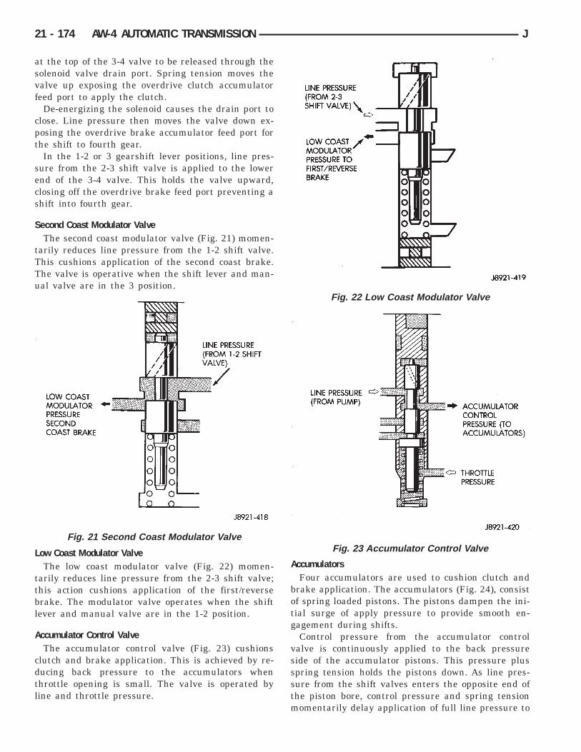
at the top of the 3-4 valve to be released through thesolenoid valve drain port. Spring tension moves thevalve up exposing the overdrive clutch accumulatorfeed port to apply the clutch.
De-energizing the solenoid causes the drain port toclose. Line pressure then moves the valve down ex-posing the overdrive brake accumulator feed port forthe shift to fourth gear.
In the 1-2 or 3 gearshift lever positions, line pres-sure from the 2-3 shift valve is applied to the lowerend of the 3-4 valve. This holds the valve upward,closing off the overdrive brake feed port preventing ashift into fourth gear.
Second Coast Modulator ValveThe second coast modulator valve (Fig. 21) momen-
tarily reduces line pressure from the 1-2 shift valve.This cushions application of the second coast brake.The valve is operative when the shift lever and man-ual valve are in the 3 position.
Low Coast Modulator ValveThe low coast modulator valve (Fig. 22) momen-
tarily reduces line pressure from the 2-3 shift valve;this action cushions application of the first/reversebrake. The modulator valve operates when the shiftlever and manual valve are in the 1-2 position.
Accumulator Control ValveThe accumulator control valve (Fig. 23) cushions
clutch and brake application. This is achieved by re-ducing back pressure to the accumulators whenthrottle opening is small. The valve is operated byline and throttle pressure.
AccumulatorsFour accumulators are used to cushion clutch and
brake application. The accumulators (Fig. 24), consistof spring loaded pistons. The pistons dampen the ini-tial surge of apply pressure to provide smooth en-gagement during shifts.
Control pressure from the accumulator controlvalve is continuously applied to the back pressureside of the accumulator pistons. This pressure plusspring tension holds the pistons down. As line pres-sure from the shift valves enters the opposite end ofthe piston bore, control pressure and spring tensionmomentarily delay application of full line pressure to
Fig. 21 Second Coast Modulator Valve
Fig. 22 Low Coast Modulator Valve
Fig. 23 Accumulator Control Valve
21 - 174 AW-4 AUTOMATIC TRANSMISSION J

cushion engagement. The accumulators are all lo-cated in the transmission case (Fig. 24).
Transmission Valve Body SolenoidsThree solenoids are used (Fig. 25). The No. 1 and 2
solenoids control shift valve operation by applying or
releasing line pressure. The signal to apply or releasepressure is provided by the transmission controlmodule.
The No. 3 solenoid controls operation of the torqueconverter clutch. The solenoid operates in response tosignals from the transmission control module.
When the No. 1 and 2 solenoids are activated, thesolenoid plunger is moved off its seat opening thedrain port to release line pressure. When either sole-noid is deactivated, the plunger closes the drain port.
The No. 3 solenoid operates in reverse. When thesolenoid is deactivated, the solenoid plunger is movedoff its seat opening the drain port to release linepressure. When the solenoid is activated, the plungercloses the drain port.
Fig. 24 Accumulators
Fig. 25 Transmission Valve Body Solenoids
J AW-4 AUTOMATIC TRANSMISSION 21 - 175

AW-4 TRANSMISSION DIAGNOSIS
INDEX
page page
General Diagnosis Information . . . . . . . . . . . . . . . 176Hydraulic Pressure Test . . . . . . . . . . . . . . . . . . . . 177Manual Shifting Test . . . . . . . . . . . . . . . . . . . . . . 177
Preliminary Inspection and Adjustment . . . . . . . . . 176Time Lag Test . . . . . . . . . . . . . . . . . . . . . . . . . . . 178Torque Converter Stall Test . . . . . . . . . . . . . . . . . 178
GENERAL DIAGNOSIS INFORMATIONShift points are controlled by the transmission con-
trol module (TCM). Before attempting repair, deter-mine if a malfunction is electrical or mechanical.
The TCM used with the AW-4 transmission has aself-diagnostic program compatible with the DRBscan tool. The tester will identify faults in the elec-trical control system.
Diagnosis should begin with the Preliminary Inspec-tion And Adjustment procedure. It is will help deter-mine if a problem is mechanical or electrical. The firstprocedure step is Initial Inspection and Adjustment.
PRELIMINARY INSPECTION AND ADJUSTMENT(1) Check and adjust transmission shift cable if
necessary.
Fig. 26 Preliminary Diagnosis Check Procedure
21 - 176 AW-4 TRANSMISSION DIAGNOSIS J

(2) Verify transmission throttle cable operation.Repair or replace cable if necessary.
(3) Check engine throttle operation. Operate accel-erator pedal and observe injector throttle plate move-ment. Adjust linkage if throttle plate does not reachwide open position.
(4) Check transmission fluid level when fluid is atnormal operating temperature. Start engine. Shifttransmission through all gear ranges then back toNeutral. Correct level is to Full or Add mark on dip-stick with engine at curb idle speed.
(5) Check and adjust park/neutral position switchif necessary.
(6) Check throttle position sensor adjustment andoperation. Adjust the sensor if necessary.
MANUAL SHIFTING TEST(1) This test determines if problem is related to
mechanical or electrical component.(2) Stop engine and disconnect transmission con-
trol module or module fuse.(3) Road test vehicle. Shift transmission into each
gear range. Transmission should operate as follows:• lock in Park• back up in Reverse• not move in Neutral• provide first gear only with shift lever in 1-2 posi-tion• operate in third gear only with shift lever in 3 po-sition• operate in overdrive fourth gear in D position
(4) If transmission operates as described, proceedto next step. However, if forward gear ranges weredifficult to distinguish (all feel the same), or vehiclewould not back up, refer to diagnosis charts. Do notperform stall or time lag tests.
CAUTION: Do not overspeed the engine during thenext test step. Ease off the throttle and allow thevehicle to slow before downshifting.
(5) Continue road test. Manually downshift trans-mission from D to 3, and from 3 to 1-2 position. Thenmanually upshift transmission through forwardranges again.
(6) If transmission operation is OK, perform stall,time lag and pressure tests. If transmission shiftingproblem is encountered, refer to diagnosis charts.
(7) If a problem still exists, continue testing withDRB scan tool.
HYDRAULIC PRESSURE TEST
PRESSURE TEST PROCEDURE(1) Connect pressure test gauge to test port on pas-
senger side of transmission. Use Adapter 7554 to con-nect gauge. Be sure test gauge has minimumcapacity of 300 psi (2100 kPa).
(2) Be sure transmission fluid is at normal operat-ing temperature.
(3) Apply parking brakes and block wheels.
WARNING: DO NOT ALLOW ANYONE TO STANDAT THE FRONT OR REAR OF THE VEHICLE WHILEPERFORMING THE FOLLOWING STEPS IN THEPRESSURE TEST.
(4) Check and adjust engine curb idle speed.(5) Apply (and hold) service brakes.(6) Shift transmission into D range and note line
pressure with engine at curb idle speed. Pressureshould be 61-to-70 psi (421-to-481 kPa).
(7) Press accelerator pedal to wide open throttleposition and note line pressure. Pressure should be173-to-209 psi (1196-to-1442 kPa).
CAUTION: Do not hold wide open throttle for morethan 3-4 seconds at a time.
(8) Shift transmission into Reverse and note linepressure with engine at curb idle speed. Pressureshould be 75-to-90 psi (519-to-618 kPa).
(9) Press accelerator to wide open throttle positionand note line pressure in Reverse. Pressure shouldbe 213-to-263 psi (1471-to-1814 kPa).
CAUTION: Do not hold wide open throttle for morethan 4 seconds.
(10) If line pressure is not within specifications,adjust transmission throttle cable and repeat pres-sure test.
Fig. 27 Pressure Test Gauge Connection
J AW-4 TRANSMISSION DIAGNOSIS 21 - 177

PRESSURE TEST ANALYSISIf pressures in D and Reverse are higher than
specified in test, check for the following:• throttle cable loose, worn, binding or out of adjust-ment• throttle valve, downshift plug, throttle cam, or pri-mary regulator valve are sticking, worn or damaged
If pressures in D and Reverse are lower than spec-ified in test, check for following:• throttle cable loose, worn, binding or out of adjust-ment• throttle valve, downshift plug, or throttle camsticking, worn or damaged• primary regulator valve sticking, worn, or dam-aged• oil pump gears or housing worn, or damaged• overdrive clutch worn, or damaged
If pressures are low in D range only, check for fol-lowing:• forward clutch worn or damaged• fluid leakage in D range circuit (component sealand O-rings)
If pressures are low in Reverse only, check for fol-lowing:• shift cable and manual valve out of adjustment• fluid leakage in reverse circuit (component sealand O-rings)• direct clutch worn or damaged• first/reverse brake worn or damaged
TORQUE CONVERTER STALL TESTStall testing checks the holding ability of the trans-
mission clutches and brakes and of the torque con-verter stator overrunning clutch. Stall speeds arechecked in both Drive and Reverse ranges withthe AW-4 transmission.
(1) Before starting test, be sure fluid level is cor-rect and fluid is at normal operating temperature.
(2) Connect tachometer to engine. Position tachom-eter so it can be viewed from drivers seat.
(3) Apply parking brakes and block wheels.(4) Apply and hold service brakes.(5) Shift transfer case into 2H position.(6) Start engine.
WARNING: DO NOT ALLOW ANYONE TO STAND ATTHE FRONT OR REAR OF THE VEHICLE DURINGTHE TEST.
(7) Shift transmission into D range.(8) Open throttle completely and record maximum
engine rpm registered on tachometer. It takes any-where from 4 to 10 seconds to reach maximum rpm.However, once maximum rpm has been achieved, donot hold wide open throttle for more than 3-4seconds.
CAUTION: Stalling the converter causes a rapid in-crease in fluid temperature. To avoid fluid overheat-ing, hold wide open throttle for no more than 4seconds after reaching peak rpm. In addition, ifmore than one stall test is required, run the engineat 1000 rpm with the transmission in Neutral for atleast 20 seconds to cool the fluid.
(9) Stall speed should be in 2100-2400 rpm rangein Drive.
(10) Release throttle, shift transmission into Neu-tral, and run engine for 20-30 seconds to cool fluid.
(11) Shift transmission into Reverse.(12) Repeat stall test described in step (8).(13) Stall speed in Reverse should also be in 2100-
2400 rpm range.(14) Release accelerator pedal, shift transmission
into Neutral, and run engine for 20-30 seconds tocool fluid.
STALL SPEED TEST ANALYSISIf engine rpm is lower than specified in D and Re-
verse, check for the following:• engine output/performance insufficient• stator overrunning clutch in torque converter notholding if engine speed was 1500 rpm or less.
If stall speed in D range is higher than specified,check for the following:• line pressure low• forward clutch slipping• No. 2 one-way clutch not holding• overdrive one-way clutch not holding
If stall speed in Reverse was higher than specified,check for the following:• line pressure low• direct clutch slipping• first/ reverse brake slipping• overdrive one-way clutch not holding
If stall speeds were higher than specified in both Dand Reverse, check for the following:• low fluid level• line pressure low• overdrive one-way clutch not holding
TIME LAG TESTThis test checks general condition of the overdrive
clutch, forward clutch, rear clutch and first/reversebrake. Condition is indicated by the amount of timerequired for clutch/brake engagement with the en-gine at curb idle speed. Engagement time is mea-sured for D and Reverse positions. A stop watch isrecommended for test accuracy.
TEST PROCEDURE(1) Check and adjust transmission fluid level if
necessary.(2) Bring transmission to normal operating tem-
perature.
21 - 178 AW-4 TRANSMISSION DIAGNOSIS J

(3) Apply parking brakes and turn off air condi-tioning unit.
(4) Shift transfer case into 2H range.(5) Start engine and check curb idle speed. Adjust
speed if necessary. Curb idle must be correct to en-sure accurate test results.
(6) Shift transmission into Neutral and set stopwatch.
(7) During following test steps, start stop watch assoon as shift lever reaches D and Reverse ranges.
(8) Shift transmission into D range and recordtime it takes for engagement. Repeat test two moretimes.
(9) Reset stop watch and shift transmission back toNeutral.
(10) Shift transmission into Reverse and recordtime it takes for engagement. Repeat test two moretimes.
(11) Engagement time in D range should be a max-imum of 1.2 seconds. Engagement time for Reverseshould be a maximum of 1.5 seconds.
TIME LAG TEST ANALYSISIf engagement time is longer than specified for D
range, check for the following:• shift cable misadjusted• line pressure low• forward clutch worn• overdrive clutch worn or damaged
If engagement time is longer than specified for Re-verse, check for the following:• shift cable misadjusted• line pressure low• direct clutch worn• first/reverse brake worn• overdrive clutch worn or damaged
J AW-4 TRANSMISSION DIAGNOSIS 21 - 179

SERVICE DIAGNOSIS
21 - 180 AW-4 TRANSMISSION DIAGNOSIS J

SERVICE DIAGNOSIS
J AW-4 TRANSMISSION DIAGNOSIS 21 - 181

AW-4 IN-VEHICLE SERVICE
INDEX
page page
Accumulator Pistons and Springs . . . . . . . . . . . . . 189Adapter Housing Seal Replacement . . . . . . . . . . . 191Checking Fluid Level and Condition . . . . . . . . . . . 182Manual Valve Shaft Seal Replacement . . . . . . . . . 187Park Interlock Cable Adjustment . . . . . . . . . . . . . 195Park Rod and Pawl Service . . . . . . . . . . . . . . . . . 190Park/Neutral Position Switch . . . . . . . . . . . . . . . . 183Refilling After Overhaul or Fluid/Filter Change . . . 182Second Coast Brake Servo . . . . . . . . . . . . . . . . . 190Shift Cable Adjustment . . . . . . . . . . . . . . . . . . . . 195Speed Sensor . . . . . . . . . . . . . . . . . . . . . . . . . . . 192
Speed Sensor Rotor—Speedometer Drive Gear . . 193Throttle Position Sensor (TPS) Service . . . . . . . . 193Transmission Control Module (TCM) Service . . . . 183Transmission Cooler Line Fittings . . . . . . . . . . . . 197Transmission Cooler Service . . . . . . . . . . . . . . . . 196Transmission Throttle Cable Adjustment . . . . . . . . 194Transmission Throttle Cable Replacement . . . . . . 193Transmission Valve Body Installation . . . . . . . . . . 187Transmission Valve Body Removal . . . . . . . . . . . 186Transmission Valve Body Solenoids . . . . . . . . . . . 184
CHECKING FLUID LEVEL AND CONDITIONRecommended fluid for AW-4 transmissions is Mo-
par Dexron IIE/Mercon.Mopar Dexron II can also be used but only when
Mercon fluid is not available.
CHECKING FLUID LEVEL(1) Be sure transmission fluid is at normal operat-
ing temperature. Normal operating temperature isreached after approximately 15 miles (25 km) of op-eration.
(2) Position vehicle on level surface. This is impor-tant for an accurate fluid level check.
(3) Shift transmission through all gear ranges andback to Park.
(4) Apply parking brakes.(5) Verify that transmission is in Park.(6) Wipe off dipstick handle to prevent dirt from
entering fill tube. Then remove dipstick and checkfluid level and condition.
(7) Correct fluid level is to FULL mark on dip-stick when fluid is at normal operating temper-ature (Fig. 1).
(8) If fluid level is low, top off level with MoparDexron IIE/Mercon. Mopar Dexron II can be used butonly if Mercon is not available. Do not overfilltransmission. Add only enough fluid to bringlevel to Full mark.
(9) If too much fluid was added, excess amount canbe removed with suction gun and appropriate diame-ter plastic tubing. Tubing only has to be long enoughto extend into oil pan.
CHECKING FLUID CONDITIONInspect the appearance of the fluid during the fluid
level check. Fluid color should range from dark red topink and be free of foreign material, or particles. Ifthe fluid is dark brown or black in color and smellsburnt, the fluid has been overheated and must bechanged.
Transmission operation should also be checked ifthe fluid is severely discolored and contains quanti-ties of foreign material, metal particles, or clutch discfriction material.
A small quantity of friction material or metalparticles in the oil pan is normal. The particlesare usually generated during the break-in pe-riod and indicate normal seating of the varioustransmission components.
REFILLING AFTER OVERHAUL OR FLUID/FILTERCHANGE
The best way to refill the transmission after a fluidchange or overhaul is as follows:
(1) If transmission has been overhauled, installtransmission in vehicle.
(2) Remove dipstick and insert clean funnel intransmission fill tube.
(3) Add following initial quantity of Mopar DexronIIE/Mercon to transmission:
(a) If fluid/filter change was performed, add 4pints (2 quarts) of fluid to transmission.
(b) If transmission was completely overhauledand torque converter was replaced or drained, add10 pints (5 quarts) of fluid to transmission.
(c) Remove funnel and install dipstick.(4) Operate vehicle until fluid reaches normal op-
erating temperature.(5) Apply parking brakes.
Fig. 1 Transmission Fluid Level
21 - 182 AW-4 IN-VEHICLE SERVICE J

(6) Let engine run at normal curb idle speed, applyservice brakes. Then shift transmission through allgear ranges and back to PARK (leave engine run-ning).
(7) Remove dipstick and check fluid level. Add onlyenough fluid to bring level to Full mark on dipstick.Do not overfill. If too much fluid is added, excessamount can be removed with suction gun andplastic tubing. Tubing only has to be longenough to extend into oil pan.
(8) When fluid level is correct, shut engine off, re-lease park brake, remove funnel, and reseat dipstickin fill tube.
TRANSMISSION CONTROL MODULE (TCM)SERVICE
Use the DRB scan tool to diagnose transmissioncontrol module function whenever a fault is sus-pected. Replace the module only when the scan toolindicates the module is actually faulty.
TRANSMISSION CONTROL MODULEREPLACEMENT
The transmission control module is mounted underthe instrument panel. On left hand drive models, it isat the driver side of the lower finish panel (Fig. 2).On right hand drive models, it is at the passengerside of the lower finish panel (Fig. 3).
To remove the module, disconnect the wire harness,remove the mounting screws and remove the modulefrom the finish panel. Tighten the module mountingscrews securely after installation. Also be sure thewire harness is not twisted, kinked or touching anybody panels.
PARK/NEUTRAL POSITION SWITCH
SWITCH TESTINGTest switch continuity with an ohmmeter. Discon-
nect the switch and check continuity at the connectorterminal positions and in the gear ranges indicatedin Figure 3. Switch continuity should be as follows:• Continuity should exist between terminals B andC with the transmission in Park and Neutral only(Fig. 4).
• Continuity should exist between terminals A and Ewith the transmission in Reverse (Fig. 4).• Continuity should exist between terminals A andG with the transmission in third gear (Fig. 4).• Continuity should exist between terminals A andH with the transmission in first and/or second gear(Fig. 4).• Continuity should not exist in D position.
PARK/NEUTRAL POSITION SWITCH REMOVAL(1) Raise vehicle.(2) Disconnect switch wire harness connector.(3) Pry washer lock tabs upward and remove
switch attaching nut and tabbed washer (Fig. 5).(4) Remove switch adjusting bolt (Fig. 5).(5) Slide switch off manual valve shaft.
PARK/NEUTRAL POSITION SWITCHINSTALLATION AND ADJUSTMENT
(1) Disconnect shift linkage rod from shift lever onleft side of transmission.
Fig. 2 TCM Location (Left Hand Drive)
Fig. 3 TCM Location (Right Hand Drive)
Fig. 4 Park/Neutral Position Switch Terminals AndTesting
J AW-4 IN-VEHICLE SERVICE 21 - 183

(2) Rotate manual shift lever all the way rearward.Then rotate lever forward two detent positions toNeutral.
(3) Install switch on manual valve shaft and in-stall switch adjusting bolt finger tight. Do not tightenbolt at this time.
(4) Install tabbed washer on manual valve shaftand install switch attaching nut. Tighten nut to 6.9Nzm (61 in. lbs.) torque but do not bend washer locktabs over nut at this time.
(5) Verify that transmission is in Neutral.(6) Rotate switch to align neutral standard line
with vertical groove on manual valve shaft (Fig. 6).(7) Align switch standard line with groove or flat
on manual valve shaft.(8) Tighten switch adjusting bolt to 13 Nzm (9 ft.
lbs.) torque.(9) Bend at least two washer lock tabs over switch
attaching nut to secure it.(10) Connect shift linkage rod to shift lever on left
side of case.(11) Connect switch wires to harness and lower ve-
hicle.(12) Check switch operation. Engine should start
in Park and Neutral only.
TRANSMISSION VALVE BODY SOLENOIDS
SOLENOID REMOVAL(1) Remove transmission oil pan drain plug and
drain fluid.(2) Remove pan bolts and remove oil pan.
(3) Remove oil screen bolts and remove screen (Fig.7) and gasket. Discard the gasket.
(4) Disconnect solenoid wire connector (Fig. 8).(5) If all solenoids are being removed, mark or tag
wires for assembly reference before disconnectingthem.
(6) Remove bolt attaching solenoids to valve bodyand remove solenoids (Fig. 9). Do not allow any valvebody components to fall out when solenoids are re-moved.
(7) Clean oil filter and pan with solvent and drywith compressed air.
(8) Remove old sealer material from oil pan andtransmission case.
Fig. 5 Park/Neutral Position Switch Removal/Installation
Fig. 6 Park/Neutral Position Switch Adjustment
Fig. 7 Oil Screen Removal/Installation
21 - 184 AW-4 IN-VEHICLE SERVICE J

Solenoid TestingTest solenoid resistance with an ohmmeter. Con-
nect the ohmmeter leads to the solenoid mountingbracket and to the solenoid wire terminal (Fig. 10).
Solenoid resistance should be 11-15 ohms. Replacethe solenoid if resistance is above or below the spec-ified range.
SOLENOID INSTALLATION(1) Position solenoids on valve body and install so-
lenoid bolts. Tighten bolts to 10 Nzm (7 ft. lbs.)torque.
(2) Connect feed wires to solenoids.(3) Install new gaskets on oil screen and install
screen. Tighten screen bolts to 10 Nzm (7 ft. lbs.)torque.
(4) Apply bead of Loctite 599 sealer to oil pan seal-ing surface. Sealer bead should be at least 3.0 mm(1/8 in.) wide.
(5) Install oil pan on transmission. Tighten panbolts to 7 Nzm (65 in. lbs.) torque.
(6) Install and tighten oil pan drain plug to 20 Nzm(15 ft. lbs.) torque.
(7) Fill transmission with Mopar Dexron IIE/Mer-con.
SOLENOID HARNESS ADAPTER SEALREPLACEMENT
(1) Remove oil pan and oil screen. Refer to Sole-noid Removal procedure.
(2) Disconnect solenoid wire connectors (Fig. 8).(3) Remove bracket securing solenoid harness
adaptor (Fig. 11) to case.
(4) Pull harness adapter and wires out of case.(5) Remove and discard adapter O-ring.
Fig. 10 Testing Transmission Valve Body Solenoid
Fig. 11 Harness Adapter Removal/Installation
Fig. 8 Solenoid Wire Connectors
Fig. 9 Transmission Valve Body Solenoids
J AW-4 IN-VEHICLE SERVICE 21 - 185

(6) Lubricate new O-ring and install it on adapter.(7) Install solenoid wire harness and adapter in
case.(8) Install adapter bracket and bracket bolt.(9) Connect wires to solenoids.(10) Install oil screen and oil pan.
TRANSMISSION VALVE BODY REMOVALRemoval and installation are the only valve body
service procedures covered in this section. Refer tothe transmission overhaul section for valve body dis-assembly, cleaning, inspection and reassembly.
(1) Remove oil pan plug and drain transmissionfluid.
(2) Remove oil pan and oil screen. Clean pan andscreen in solvent and dry them with compressed air.
(3) Disconnect solenoid wire connectors (Fig. 8).Mark wires for assembly reference.
(4) Remove valve body oil tubes (Fig. 12). Carefullypry tubes out of valve body with screwdriver.
(5) Disconnect throttle cable from throttle cam(Fig. 13).
(6) Remove valve body bolts. Bolt locations are out-lined in Figure 14.
(7) Lower valve body and remove overdrive clutchaccumulator springs, direct clutch accumulatorsprings and second brake accumulator spring (Fig.15)
(8) Remove valve body and check ball and spring(Fig. 16).
Fig. 13 Removing/Installing Throttle Cable
Fig. 14 Transmission Valve Body Bolt Locations
Fig. 15 Accumulator Springs
Fig. 12 Removing Transmission Valve Body OilTubes
21 - 186 AW-4 IN-VEHICLE SERVICE J

TRANSMISSION VALVE BODY INSTALLATION(1) Connect cable to throttle cam (Fig. 13).(2) Install check ball and spring (Fig. 16).(3) Position accumulator springs and spacers on
valve body.(4) Align valve body manual valve with shift sector
(Fig. 17) and carefully position valve body on case.
(5) Install valve body bolts (Fig. 14). Tighten boltsevenly to 10 Nzm (7 ft. lbs.) torque.
(6) Install valve body oil tubes. Be sure tube ends(L) and (M) are installed as shown in Figure 18.
(7) Remove old sealer material from oil pan andtransmission case.
(8) Clean oil screen and oil pan with solvent (if notdone previously). Dry both components with com-pressed air only. Do not use shop towels.
(9) Install new gaskets on oil screen and installscreen on case. Tighten screen attaching bolts to 10Nzm (7 ft. lbs.) torque.
(10) Apply bead of Mopar or Loctite 599 sealer tosealing surface of oil pan. Sealer bead should be atleast 3 mm (1/8 in.) wide. Then install oil pan andtighten pan bolts to 7.4 Nzm (65 in. lbs.) torque.
(11) Install new gasket on oil pan drain plug andinstall plug in pan. Tighten plug to 20 Nzm (15 ft.lbs.) torque.
(12) Fill transmission with Mopar Dexron IIE/Mer-con.
MANUAL VALVE SHAFT SEAL REPLACEMENT
Fig. 16 Removing/Installing Check Ball And Spring
Fig. 17 Shift Sector And Manual Valve Alignment
Fig. 18 Installing Transmission Valve Body Oil Tubes
Fig. 19 Manual Valve Shaft And Seals
J AW-4 IN-VEHICLE SERVICE 21 - 187

(1) Remove park/neutral position switch and dis-connect transmission shift lever.
(2) Remove oil pan and valve body.(3) Remove bolts attaching park rod bracket to
case (Fig. 20).
(4) Remove park rod from shift sector (Fig. 21).
(5) Cut spacer sleeve with chisel and remove itfrom manual valve shaft (Fig. 22).
(6) Remove pin from shaft and sector with pinpunch.
(7) Remove shaft and sector from case.(8) Pry shaft seals out of case (Fig. 23).
(9) Inspect the manual valve shaft and sector. Re-place either component if worn or damaged.
(10) Coat replacement shaft seals with petroleumjelly and seat them in the case (Fig. 24).
(11) Install new spacer sleeve on sector (Fig. 25).(12) Lubricate manual valve shaft with petroleum
jelly and install it in case.(13) Lubricate sector and sleeve with petroleum
jelly and install them on shaft.(14) Align hole in spacer sleeve with notch in sec-
tor. Then install shift sector roll pin. Tap pin intosector and shaft and stake sleeve to sector and shaftsecurely.
Fig. 20 Removing/Installing Park Rod Bracket
Fig. 21 Removing/Installing Park Rod
Fig. 22 Cutting Spacer Sleeve
Fig. 23 Removing Manual Valve Shaft Seals
21 - 188 AW-4 IN-VEHICLE SERVICE J

(15) Connect park rod to sector (Fig. 21).(16) Install park rod bracket (Fig. 26). Tighten
bracket bolts to 10 Nzm (7 ft. lbs.) torque.(17) Install valve body, oil screen and oil pan. Use
Mopar or Loctite 599 sealer on oil pan seal surface.(18) Install park/neutral position switch.
ACCUMULATOR PISTONS AND SPRINGS
ACCUMULATOR PISTON AND SPRINGREMOVAL
(1) Remove valve body. Refer to procedure in thissection.
(2) Remove accumulator pistons with compressedair (Fig. 27). Apply air through small feed hole nextto each piston bore. Catch each piston in a shoptowel as it exits bore.
CAUTION: Use only enough air pressure to easeeach piston out of the bore. In addition, remove thepistons one at a time and tag the pistons andsprings for assembly reference. Do not intermixthem.
(3) Remove and discard piston O-ring seals. Thenclean pistons and springs with solvent.
Fig. 24 Installing Manual Valve Shaft Seals
Fig. 25 Installing Spacer Sleeve On Sector
Fig. 26 Installing Park Rod Bracket
Fig. 27 Accumulator Piston Removal
J AW-4 IN-VEHICLE SERVICE 21 - 189

(4) Inspect pistons, springs and piston bores. Re-place worn damaged pistons. Replace broken, col-lapsed or distorted springs. Replace case if pistonbores are damaged.
(5) If small cushion spring in any piston must bereplaced, remove spring retainer clip and removespring from piston (Fig. 28). A small hooked tool orsmall thin blade screwdriver can be used to removeclip. A thin wall, deep socket, or pin punch can beused to reseat clip after spring replacement.
(6) Install new O-ring seals on pistons. Lubricateseals and pistons and piston bores with transmissionfluid.
(7) Install pistons and springs (Fig. 29).(8) Install valve body, oil screen and oil pan. Use
Mopar or Loctite 599 on oil pan sealing surface.
SECOND COAST BRAKE SERVO
SERVO OVERHAUL(1) Remove valve body as outlined in this section.(2) Remove servo piston cover snap ring with snap
ring pliers (Fig. 30).(3) Remove servo piston and cover with com-
pressed air. Apply compressed air through oil hole inservo boss to ease piston out of bore (Fig. 31).
(4) Remove and discard seal and O-rings fromcover and piston (Fig. 32). Inspect E-ring, piston,spring and retainer, piston rod and piston spring. Re-place worn or damaged parts.
(5) Install new seals on cover and piston.(6) Lubricate servo components with transmission
fluid.(7) Assemble and install servo components in case.
Be sure servo piston rod is properly engaged in thesecond coast brake band.
(8) Compress cover and piston and install coversnap ring.
(9) Install valve body, oil screen and oil pan. UseLoctite 599 on oil pan sealing surface.
PARK ROD AND PAWL SERVICE(1) Remove valve body as outlined in this section.(2) Remove bolts attaching park rod bracket to
case (Fig. 33).
Fig. 29 Accumulator Pistons, Springs And Spacers
Fig. 30 Removing/Installing Servo Piston CoverSnap Ring
Fig. 28 Small Cushion Spring Retention
21 - 190 AW-4 IN-VEHICLE SERVICE J

(3) Remove park rod from manual valve shaft sec-tor (Fig. 34).
(4) Remove park rod.(5) Remove park pawl, pin and spring (Fig. 35).(6) Examine park rod, pawl, pin and spring. Re-
place any component that is worn or damaged.(7) Install pawl in case. Insert pin and install
spring. Be sure spring is positioned as shown in Fig-ure 35.
(8) Install park rod and bracket (Fig. 33). Tightenbracket bolts to 10 Nzm (7 ft. lbs.) torque.
(9) Install valve body, oil screen and oil pan as out-lined in this section.
ADAPTER HOUSING SEAL REPLACEMENT(1) Raise vehicle.(2) Disconnect or remove components necessary to
gain access to seal (e.g. propeller shaft, crossmember,shift linkage, transfer case, exhaust components,hoses, wires).
(3) Remove dust shield and remove seal fromadapter housing (Fig. 36).
(4) Install new seal with appropriate size seal in-staller and install dust shield.
(5) Reinstall components removed to gain access toseal.
(6) Top off transmission fluid if necessary.
Fig. 31 Removing Servo Cover And Piston
Fig. 32 Second Coast Brake Servo Components
Fig. 33 Removing/Installing Park Rod Bracket
Fig. 34 Removing/Installing Park Rod
J AW-4 IN-VEHICLE SERVICE 21 - 191

SPEED SENSOR
SPEED SENSOR TESTINGTest the speed sensor with an ohmmeter. Place the
ohmmeter leads on the terminals in the sensor con-nector (Fig. 37).
Rotate the transmission output shaft and observethe ohmmeter needle. The needle should deflect indi-cating the switch is opening/closing as the rotor
moves past the sensor (Fig. 37). Replace the sensor ifthe ohmmeter does not display any kind of reading.
If a digital ohmmeter is being used, the sensorshould generate an ohmmeter readout each time theswitch opens and closes.
SPEED SENSOR REPLACEMENT(1) Disconnect sensor wire harness connector.(2) Remove sensor retainer bolt and remove sensor
(Fig. 38).
(3) Remove and discard speed sensor O-ring.
Fig. 35 Removing/Installing Park Pawl, Pin AndSpring
Fig. 36 Adapter Housing Seals
Fig. 37 Speed Sensor Testing
Fig. 38 Transmission Speed Sensor Removal/Installation
21 - 192 AW-4 IN-VEHICLE SERVICE J

(4) Install new O-ring on speed sensor and installsensor in transmission case.
(5) Install sensor bracket and retainer bolt.Tighten bolt to 7.4 Nzm (65 in. lbs.) torque.
(6) Connect sensor wire harness connector.
SPEED SENSOR ROTOR—SPEEDOMETER DRIVEGEAR
ROTOR—DRIVE GEAR REMOVAL(1) Raise vehicle.(2) Remove components necessary to gain access to
rotor and drive gear such as propeller shaft, transfercase, crossmember, and shift linkage.
(3) Disconnect speedometer cable and/or speed sen-sor.
(4) Remove adaptor housing.(5) Remove speedometer drive gear snap ring (Fig.
39).
(6) Remove the speedometer drive gear and spacer(if equipped).
(7) Remove rotor by carefully prying it off outputshaft with wood dowel or hammer handle (Fig. 40).
(8) Clean sealing surfaces of transmission case andextension/adaptor housing.
ROTOR AND DRIVE GEAR INSTALLATION(1) Install rotor, spacer (if equipped) and drive gear
on output shaft. Then install drive gear snap ring(Fig. 39).
(2) Apply bead of Loctite 599 sealer, to transmis-sion case sealing surface and install extension/adapter housing on case.
(3) Tighten adaptor housing bolts to 34 Nzm (25 ft.lbs.) torque.
(4) Install components removed to gain access torotor and drive gear.
THROTTLE POSITION SENSOR (TPS) SERVICEA separate throttle position sensor is used for au-
tomatic transmission applications. The sensor is at-tached to the base of the throttle body. Refer toGroup 14 for TPS service and adjustment.
TRANSMISSION THROTTLE CABLE REPLACEMENT
THROTTLE CABLE REMOVAL(1) In engine compartment, disconnect cable from
throttle linkage. Then compress cable mounting earsand remove cable from engine bracket (Fig. 41).
(2) Raise vehicle.(3) Remove transmission oil pan.(4) Disengage cable from throttle valve cam (Fig.
42).(5) Remove cable bracket bolt and remove cable
and bracket from case (Fig. 43).(6) Remove and discard cable seal.
THROTTLE CABLE INSTALLATION(1) Lubricate and install new seal on cable.(2) Insert cable in transmission case.(3) Attach cable to throttle cam (Fig. 42).(4) Install cable bracket on case and tighten at-
taching bolt to 10 Nzm (7 ft-lbs) torque (Fig. 43).(5) Remove old sealer material from oil pan and
transmission case. Clean oil pan with solvent and dryit with compressed air.
Fig. 40 Removing Speed Sensor Rotor
Fig. 39 Removing/Installation Speedometer DriveGear
J AW-4 IN-VEHICLE SERVICE 21 - 193

(6) Apply bead of Loctite 599 sealer to oil pan seal-ing surface. Sealer bead should be at least 3 mm (1/8in.) wide. Then install pan and tighten pan bolts to 7Nzm (65 in. lbs.) torque.
(7) Install new gasket on oil pan drain plug. Installand tighten plug to 20 Nzm (15 ft. lbs.) torque.
(8) Connect cable to engine bracket and throttlelinkage.
(9) Fill transmission with Mopar Dexron/MerconIIE.
(10) Adjust the cable as described in cable adjust-ment procedure.
TRANSMISSION THROTTLE CABLE ADJUSTMENT(1) Shift transmission into Park, shut engine off
and raise hood.(2) Press cable release button (Fig. 44).(3) Push cable conduit back into cable sheath as
far as possible (Fig. 45).(4) Rotate lever on throttle body to wide open
throttle position. Cable will ratchet to correct adjust-ment point as lever is rotated (Fig. 45).
Fig. 43 Removing/Installing Transmission ThrottleCable And Bracket
Fig. 41 Transmission Throttle Cable Attachment
Fig. 42 Removing/Installing Transmission ThrottleCable
21 - 194 AW-4 IN-VEHICLE SERVICE J

SHIFT CABLE ADJUSTMENT(1) Shift transmission into Park.(2) Raise vehicle.(3) Release cable adjuster clamp to unlock cable
(Figs. 46 and 47). Clamp is at transmission end of ca-ble.
(4) Unsnap cable from transmission cable bracket(Figs. 46 and 47).
(5) Move transmission shift lever fully rearward toPark detent. Lever is on manual valve shaft at driverside of case.
(6) Verify positive engagement of park lock by at-tempting to rotate propeller shaft. Shaft will not ro-tate when park lock is engaged.
(7) Snap cable into cable bracket.
(8) Lock shift cable by pressing cable adjusterclamp down until it snaps into place.
(9) Check engine starting. Engine should start onlyin Park and Neutral.
(10) Lower vehicle.
PARK INTERLOCK CABLE ADJUSTMENT(1) Shift transmission into Park.(2) Turn ignition switch to Lock position.(3) Remove shift lever bezel and console screws.
Raise bezel and console for access to cable.(4) Pull cable lock button up to release cable (Fig.
47).(5) Pull cable forward. Then release cable and
press cable lock button down until it snaps in place.(6) Check adjustment as follows:
Fig. 45 Throttle Cable Adjustment
Fig. 46 Shift and Interlock Cables
Fig. 44 Throttle Cable Components
J AW-4 IN-VEHICLE SERVICE 21 - 195

(a) Check movement of release shift handle but-ton (floor shift) or release lever (column shift). Youshould not be able to press button inward or movecolumn lever.
(b) Turn ignition switch to On position.(c) Press floor shift lever release button or move
column lever. Then shift into Neutral. If cable ad-justment is correct, ignition switch can not beturned to Lock position. Perform same check withtransmission in D range.(7) Move shift lever back to Park and check igni-
tion switch operation. You should be able to turnswitch to Lock position and shift lever release button/lever should not move.
TRANSMISSION COOLER SERVICE
Main CoolerThe transmission main cooler is located in the ra-
diator. The main cooler can be flushed when neces-sary, however, the cooler is not a repairablecomponent. If the cooler is damaged, plugged, orleaking, the radiator will have to be replaced.
Auxiliary CoolerThe auxiliary cooler is mounted in front of the ra-
diator at the driver side of the vehicle (Fig. 48). Thecooler can be flushed when necessary, while mounted
in the vehicle. The cooler can also be removed for ac-cess, repair, or replacement as needed.
The main and auxiliary coolers should both beflushed whenever a transmission or converter clutchmalfunction generates sludge, debris, or particles ofclutch friction material.
Cooler ServiceThe main cooler (and radiator) and the auxiliary
cooler can be removed for service or access to othercomponents. Auxiliary cooler removal requires that
Fig. 47 Park Lock Cable Attachment
Fig. 48 Auxiliary Cooler Mounting (Left Hand Drive)
21 - 196 AW-4 IN-VEHICLE SERVICE J

the front bumper and radiator support be removedfor access to the cooler lines and attaching bracket.
REVERSE FLUSHING MAIN AND AUXILIARYCOOLERS AND COOLER LINES
Reverse flushing the cooler and lines will preventsludge and particles from flowing back into thetransmission after repair. The flushing procedure ap-plies to standard (in-radiator) coolers and auxiliarycoolers equally.
Pressure equipment is preferred for reverse flush-ing. However, reverse flushing can be performed us-ing hand operated equipment as described in thefollowing procedure.
(1) Disconnect cooler lines at transmission and atauxiliary cooler (Figs. 48 and 49).
(2) Position drain pan under cooler line to catchmaterial flushed through coolers and lines.
(3) Reverse flush each cooler using hand operatedsuction gun filled with mineral spirits. Insert gunnozzle (or hose) into cooler inlet (return) line. Thenforce mineral spirits through into line and throughcooler.
(4) Continue reverse flushing until fluid exiting in-let (pressure) line is clear and free of debris/residue.
(5) Replace radiator if fluid cannot be pumpedthrough main cooler. Replace auxiliary cooler if leaksare evident, or if fluid cannot be pumped through it.
(6) Clear flushing materials from coolers and lineswith short pulses of compressed air. Insert air gunnozzle into cooler inlet (return) line and continueshort pulses of air until all fluid is cleared fromcooler and lines.
(7) Pump one quart of fresh automatic transmis-sion fluid through cooler and lines before reconnect-ing cooler lines.
FLOW TESTING TRANSMISSION MAINCOOLER
Cooler flow is checked by measuring the amount offluid flow through the cooler in a 20 second time pe-riod. The test is performed with the engine runningand transmission in neutral. Fluid is then pumpedthrough the cooler by the transmission oil pump.
(1) Disconnect cooler inlet line at transmission fit-ting.
(2) Securely attach hose to end of inlet line and po-sition line in a one quart test container.
(3) Add extra quart of fluid to transmission.(4) Use stopwatch to check flow test time.(5) Shift transmission into neutral and set parking
brake.(6) Start and run engine at curb idle speed and im-
mediately note cooler flow. Approximately one quartof fluid should flow into test container in 20 secondperiod.
(7) If cooler flow is intermittent, flows less thanone quart in 20 seconds, or does not flow at all,cooler is faulty and must be replaced.
TRANSMISSION COOLER LINE FITTINGSQuick connect fittings are used at the transmission
cooler line connections. The fitting seals and guidesare serviceable.
Replace the seals and guides whenever the fittingsexhibit leakage, or will not properly snap into place.
Fig. 49 Auxiliary Cooler Mounting (Right Hand Drive)
J AW-4 IN-VEHICLE SERVICE 21 - 197

AW-4 TRANSMISSION REMOVAL AND INSTALLATION
INDEX
page page
Oil Pump Seal Replacement . . . . . . . . . . . . . . . . 199Torque Converter Stator Clutch Inspection . . . . . . 199
Transmission and Torque Converter Installation . . 199Transmission and Torque Converter Removal . . . . 198
TRANSMISSION AND TORQUE CONVERTERREMOVAL
(1) Raise vehicle.(2) Drain transmission fluid and reinstall oil pan
drain plug.(3) On models with 2-piece fill tube, remove upper
half of tube (Fig. 1).
(4) Disconnect cooler lines at transmission. Coolerlines have quick-disconnect fittings. Press fitting re-lease tabs and pull cooler lines and fittings out ofcase or use Special Tool 7555 to disconnect them.
(5) Support engine with safety stand and supporttransmission with jack.
(6) Disconnect transmission and transfer case shiftlinkage.
(7) Remove necessary exhaust components.(8) Disconnect vehicle speed sensor wires(9) Mark position of front and rear propeller shafts
for alignment reference. Then remove shafts from ve-hicle.
(10) Remove rear crossmember.(11) Disconnect transmission shift cable at trans-
mission. Then disconnect transmission throttle valvecable at engine.
(12) Disconnect necessary vacuum and fluid hoses.(13) Remove transfer case from transmission.(14) Disconnect and remove crankshaft position
sensor (Fig. 2).
CAUTION: The crankshaft position sensor can bedamaged during transmission removal (or installa-tion) if the sensor is still bolted to the engine block.To avoid damage, remove the sensor before remov-ing the transmission.
(15) Remove starter motor.(16) Remove bolts attaching converter to drive
plate.(17) Remove bolts attaching converter housing to
engine.(18) Secure transmission to jack with safety
chains.(19) Pull transmission rearward for access to con-
verter. Then secure converter in pump with C-clampor strap bolted to converter housing.
(20) Remove transmission from under vehicle.(21) Remove torque converter if converter or oil
pump seal are to be serviced.
Fig. 1 Transmission Fill Tube (Two-Piece)Fig. 2 Crankshaft Position Sensor
21 - 198 AW-4 TRANSMISSION REMOVAL AND INSTALLATION J

TORQUE CONVERTER STATOR CLUTCHINSPECTION
(1) Insert Rotating Tool 7547 into converter huband seat tool in one-way clutch (Fig. 3).
(2) Insert Stopper Tool 7548 in one converter hubnotch and into outer race of rotating tool.
(3) Turn rotating tool clockwise. Converter clutchshould rotate freely and smoothly. Less than 2.5 Nzm(22 in. lbs.) of torque should be required to rotateclutch in clockwise direction.
(4) Turn rotating tool in counterclockwise direction.Converter clutch should lock.
(5) Replace converter if clutch binds or will notlock.
OIL PUMP SEAL REPLACEMENT(1) Remove converter.(2) Remove old seal. Use blunt punch to collapse
seal and pry seal out of pump housing. Do notscratch or damage seal bore.
(3) Lubricate lip of new seal with transmissionfluid and install seal in pump with tool 7549 (Fig. 4).
(4) Lubricate converter drive hub with transmis-sion fluid.
(5) Align and install converter in oil pump.
TRANSMISSION AND TORQUE CONVERTERINSTALLATION
(1) Mount transmission on transmission jack. Thensecure transmission to jack with safety chains.
(2) Lubricate converter drive hub and oil pumpseal lip with transmission fluid. Then install con-verter. Be sure converter is fully seated in oil pumpgears before proceeding. Hold converter in place withC-clamp or strap attached to converter housing.
(3) Align and position transmission and converteron engine.
(4) Remove clamp or strap used to hold torque con-verter in place.
(5) Move transmission forward seat and it on en-gine. Be sure torque converter hub is fully seated.
(6) Install converter housing-to-engine bolts (Fig.5).
(7) Install converter-to-drive plate bolts.(8) Install and connect starter motor.(9) Install and connect crankshaft position sensor.(10) Install transfer case on transmission. Tighten
transfer case attaching nuts to 41 Nzm (30 ft. lbs.)torque
(11) Connect transfer case shift linkage and vac-uum hoses.
(12) Connect exhaust components.(13) Install rear crossmember and remove jack
used to support transmission assembly.(14) Connect speed sensor wire harness to sensor.(15) Connect wire harness to park/neutral position
switch.(16) Align and connect front and rear propeller
shafts.
Fig. 3 Checking Operation Of Torque ConverterStator One-Way Clutch
J AW-4 TRANSMISSION REMOVAL AND INSTALLATION 21 - 199

(17) Connect transmission wire harnesses andtransfer case vacuum and wire harnesses.
(18) Connect transmission cooler lines.(19) Connect transmission throttle cable at engine.(20) Install new O-ring seal on upper half of trans-
mission fill tube. Then connect upper and lower tubehalves.
(21) Lower vehicle.(22) Fill transmission with Mopar Dexron IIE/Mer-
con automatic transmission fluid.
Fig. 5 Transmission Mounting
Fig. 4 Installing Oil Pump Seal
21 - 200 AW-4 TRANSMISSION REMOVAL AND INSTALLATION J

AW-4 TRANSMISSION OVERHAUL
INDEX
page page
Cleaning and Inspection . . . . . . . . . . . . . . . . . . . 214Direct Clutch Overhaul . . . . . . . . . . . . . . . . . . . . 228First-Reverse Brake Piston and Transmission Case
Overhaul . . . . . . . . . . . . . . . . . . . . . . . . . . . . . 247Forward Clutch Overhaul . . . . . . . . . . . . . . . . . . . 232Front Planetary Gear Overhaul . . . . . . . . . . . . . . 237Manual Valve Shaft Overhaul . . . . . . . . . . . . . . . 215Oil Pump Overhaul . . . . . . . . . . . . . . . . . . . . . . . 216Overdrive Planetary Gear and Clutch Overhaul . . 218
Overdrive Support Overhaul . . . . . . . . . . . . . . . . 226Overhaul Service Tools . . . . . . . . . . . . . . . . . . . . 201Rear Planetary, No. 2 One-Way Clutch and Output
Shaft Overhaul . . . . . . . . . . . . . . . . . . . . . . . . . 244Second Brake Overhaul . . . . . . . . . . . . . . . . . . . 241Sun Gear and No. 1 One-Way Clutch Overhaul . . 238Transmission Assembly and Adjustment . . . . . . . . 265Transmission Disassembly . . . . . . . . . . . . . . . . . 201Transmission Valve Body Overhaul . . . . . . . . . . . 250
OVERHAUL SERVICE TOOLSThe special tools needed to overhaul the AW-4
transmission are provided in Tool Kit 6294. However,Pressure Test Port Adapter 7554 is not included inthis kit and must be ordered separately. The over-haul tool kit and test port adapter are availablethrough the parts division and dealer special toolprogram.
TRANSMISSION DISASSEMBLY(1) Remove torque converter.(2) Remove lower half of filler tube if not previ-
ously removed.(3) Remove clamps attaching wire harness and
throttle cable (Fig. 1) to transmission.
(4) Remove shift lever from manual valve shaft atleft side of transmission.
(5) Remove park/neutral position switch.(6) Remove speed sensor (Fig. 2).
Fig. 1 Typical Harness And Cable Clamp Attachment
Fig. 2 Speed Sensor Removal
J AW-4 TRANSMISSION OVERHAUL 21 - 201

(7) Remove converter housing bolts and removehousing (Fig. 3) from case.
(8) Remove adapter housing.(9) Remove speedometer drive gear snap ring and
remove gear and gear spacer if equipped (Fig. 4).
(10) Remove speed sensor rotor and key. Use wooddowel or hammer handle to loosen and remove rotor(Fig. 5).
(11) Remove transmission oil pan, oil screen andscreen gaskets (Fig. 6). Then mount transmission inholding fixture.
Fig. 3 Converter Housing Removal
Fig. 4 Removing Speed Sensor And SpeedometerDrive Gear
Fig. 5 Removing Transmission Speed Sensor Rotor
Fig. 6 Removing Oil Screen
21 - 202 AW-4 TRANSMISSION OVERHAUL J

(12) Remove valve body oil feed tubes (Fig. 7).
(13) Disconnect valve body solenoid wires (Fig. 8).
(14) Remove harness bracket bolt and remove har-ness and bracket Fig. 9).
(15) Remove valve body bolts (Fig. 10).(16) Disconnect throttle cable from throttle cam
(Fig. 11).
Fig. 9 Removing Bracket And Harness
Fig. 10 Valve Body Bolt Locations
Fig. 11 Disconnecting Throttle Cable
Fig. 7 Valve Body Oil Tube Removal
Fig. 8 Solenoid Wire Location
J AW-4 TRANSMISSION OVERHAUL 21 - 203

(17) Remove valve body from case. Then remove ac-cumulator springs, spacers and check ball and spring(Fig. 12).
(18) Remove second brake and clutch accumulatorpistons with compressed air (Fig. 13). Apply air pres-sure through feed port and ease the pistons out ofthe bore.
(19) Remove overdrive brake accumulator pistonwith compressed air (Fig. 13).
(20) Remove overdrive clutch accumulator pistonwith compressed air (Fig. 13).
(21) Remove throttle cable.
Fig. 12 Removing Accumulator Springs, SpacersAnd Check Ball
Fig. 13 Accumulator Piston Removal
21 - 204 AW-4 TRANSMISSION OVERHAUL J

(22) Remove oil pump bolts and remove pump withbridge-type Puller 7536 (Fig. 14).
(23) Remove race from oil pump (Fig. 15).
(24) Remove overdrive planetary gear and clutchassembly (Fig. 16).
(25) Remove race from overdrive planetary (Fig.17).
Fig. 14 Oil Pump Removal
Fig. 15 Oil Pump Race Removal
Fig. 16 Removing Overdrive PlanetaryAnd Clutch Assembly
Fig. 17 Overdrive Planetary Race Removal
J AW-4 TRANSMISSION OVERHAUL 21 - 205

(26) Remove thrust bearing, race and overdriveplanetary ring gear (Fig. 18).
(27) Measure stroke length of overdrive brake pis-ton as follows:
(a) Mount dial indicator on case (Fig. 19).(b) Mount Gauge Tool 7546 so it contacts piston
(Fig. 19).
(c) Apply 57-114 psi air pressure through piston ap-ply port and note piston stroke on dial indicator. Strokelength should be: 1.40 - 1.70 mm (0.055 - 0.0699 in.).
(d) If stroke is not within limits, replace pistonand retainer.(28) Remove overdrive brake snap ring (Fig. 20).
Fig. 18 Removing Bearing, Race AndPlanetary Ring Gear
Fig. 19 Measuring Overdrive Brake Piston Stroke
Fig. 20 Removing Overdrive Brake Snap Ring
21 - 206 AW-4 TRANSMISSION OVERHAUL J

(29) Remove overdrive brake clutch pack (Fig. 21).Then measure disc thickness with a micrometer.Minimum disc thickness is 1.84 mm (0.0724 in.). Re-place clutch pack if necessary.
(30) Remove overdrive support lower race and up-per bearing and race assembly (Fig. 22).
(31) Remove overdrive support bolts (Fig. 23).
(32) Remove overdrive support snap ring withSnap Ring Plier Tool 7540 (Fig. 24).
Fig. 21 Removing/Measuring Overdrive Brake DiscThickness
Fig. 22 Overdrive Support Bearing/Race Removal
Fig. 23 Overdrive Support Bolt Removal
Fig. 24 Removing/Installing Overdrive Support SnapRing
J AW-4 TRANSMISSION OVERHAUL 21 - 207

(33) Remove overdrive support (Fig. 25) withbridge-type Puller 7536.
(34) Remove race from hub of overdrive support(Fig. 26).
(35) Measure stroke length of second coast brakepiston rod as follows:
(a) Make reference mark on piston rod (Fig. 27)as shown.
(b) Apply 57-114 psi air pressure through pistonfeed hole and check stroke length with Gauge Tool7552 (Fig. 27).
(c) Stroke length should be 1.5 - 3.0 mm (0.059 -0.118 in.).
(d) If stroke length is incorrect, install new pis-ton rod and recheck stroke. If stroke is still incor-rect, replace second coast brake band.
(e) Replacement piston rods are available in twodifferent lengths which are: 71.4 mm (2.811 in.)and 72.9 mm (2.870 in.).
Fig. 25 Removing Overdrive Support
Fig. 26 Remove Overdrive Support Race
Fig. 27 Measuring Second Coast Brake Piston RodStroke
21 - 208 AW-4 TRANSMISSION OVERHAUL J

(36) Remove second coast brake piston snap ringwith Snap Ring Plier Tool 7540. Then remove pistoncover and piston assembly with compressed air ap-plied through piston feed hole (Fig. 28).
(37) Disassemble second coast brake piston (Fig.29).
(38) Remove direct and forward clutch assembly(Fig. 30).
(39) Remove thrust bearing and race from clutchhub (Fig. 31).
Fig. 28 Removing Second Coast Brake Cover AndPiston
Fig. 29 Second Coast Brake Piston Components
Fig. 30 Removing Direct And Forward ClutchAssembly
Fig. 31 Bearing And Race Removal From ClutchHub
J AW-4 TRANSMISSION OVERHAUL 21 - 209

(40) Remove second coast brake band E-ring fromband pin and remove brake band (Fig. 32).
(41) Remove front planetary ring gear front bearingrace and remove front planetary ring gear (Fig. 33).
(42) Remove thrust bearing and rear race fromring gear (Fig. 34).
Fig. 32 Second Coast Brake Band Removal
Fig. 33 Front Planetary Ring Gear Removal
Fig. 34 Removing Ring Gear Bearing And Rear Race
21 - 210 AW-4 TRANSMISSION OVERHAUL J

(43) Remove planetary thrust race (Fig. 35).(44) Relieve load on planetary snap ring as follows:
Loosen transmission holding fixture. Turn transmis-sion over and allow output shaft to support transmis-sion weight. Place wood blocks under shaft to protectsplines (Fig. 35).
(45) Remove planetary snap ring and remove plan-etary gear (Fig. 36).
(46) Remove sun gear, input drum and one-wayclutch as assembly (Fig. 37).
Fig. 35 Relieving Load On Planetary Snap Ring
Fig. 36 Removing Planetary Snap Ring And Gear
Fig. 37 Removing Sun Gear, Input Drum AndOne-Way Clutch
J AW-4 TRANSMISSION OVERHAUL 21 - 211

(47) Measure second brake clutch pack clearance(Fig. 38). Clearance should be 0.62 - 1.98 mm (0.0244- 0.0780 in.). Replace discs if clearance is not withinspecifications.
(48) Remove second brake clutch pack snap ring(Fig. 39).
(49) Remove second brake clutch pack (Fig. 40).Measure disc thickness with micrometer. Minimumthickness should be 1.84 mm (0.0724 in.). Replacediscs if not within specifications.
(50) Remove bolts attaching park rod bracket tocase. Then disconnect park rod from manual shaft le-ver and remove rod and bracket (Fig. 41).
Fig. 40 Removing/Measuring Second Brake ClutchDisc Thickness
Fig. 41 Removing Park Rod And Bracket
Fig. 38 Checking Second Brake Clutch PackClearance
Fig. 39 Removing Second Brake Clutch Pack SnapRing
21 - 212 AW-4 TRANSMISSION OVERHAUL J

(51) Remove park pawl spring, pin and pawl (Fig.42).
(52) Measure clearance of first-reverse brakeclutch pack (Fig. 43). Clearance should be: 0.70 - 1.2mm (0.028 - 0.047 in.). Replace discs if clearance isnot as specified.
(53) Remove second brake piston sleeve (Fig. 44).Cover remover tool with tape to avoid damaging case.
(54) Remove rear planetary gear, second brakedrum and output shaft as an assembly (Fig. 45).Fig. 42 Removing Park Pawl, Pin And Spring
Fig. 43 Checking First-Reverse Brake Clutch PackClearance
Fig. 44 Removing Second Brake Piston Sleeve
Fig. 45 Removing Rear Planetary, Second BrakeDrum And Output Shaft
J AW-4 TRANSMISSION OVERHAUL 21 - 213

(55) Remove planetary and brake drum thrustbearing and race assembly (Fig. 46).
(56) Remove second brake drum gasket from casewith gasket scraper or screwdriver (Fig. 47). Retaintube shaped gasket if condition is OK.
(57) Measure inside diameter of transmission caserear bushing with bore gauge or inside micrometer(Fig. 48). Maximum allowable diameter is 38.18 mm(1.5031 in.). Replace transmission case if bush-ing I.D. is greater than specified. Bushing is notserviceable.
CLEANING AND INSPECTIONClean the transmission components with solvent
and dry them with compressed air only. Do not useshop towels or rags.
Blow compressed air through all oil feed passagesand channels to be sure they are clear. Inspect thetransmission components for wear and damage. Re-place components that are damaged or worn beyondthe limits specified in the individual overhaul proce-dures.
Replace all O-rings, gaskets and seals. These com-ponents are not reusable. Also replace any snap ringthat is distorted or damaged.
During overhaul assembly operations, lubricate thetransmission components with Jeep or Mopar Mer-con™ automatic transmission fluid or petroleum jellyas indicated. Petroleum jelly should be used to prelu-bricate thrust bearings, washers and races. It canalso be used to hold parts in position during assem-bly.
Soak replacement clutch and brake pack com-ponents in transmission fluid for at least 30minutes before installation.
Fig. 46 Removing Planetary And Brake Drum ThrustBearing And Race Assembly
Fig. 47 Removing Brake Drum Gasket
Fig. 48 Checking Rear Bushing Inside Diameter
21 - 214 AW-4 TRANSMISSION OVERHAUL J

MANUAL VALVE SHAFT OVERHAUL
(1) Cut shaft spacer sleeve in half with chisel andremove it from lever and shaft (Fig. 2).
(2) Remove shift sector retaining pin with pinpunch (Fig. 3).
(3) Pull shaft out of case and remove manual lever.(4) Carefully pry shaft seals from case.(5) Lubricate new seals with petroleum jelly and
install them in case (Fig. 4).(6) Install new spacer sleeve on shift sector (Fig.
5).
(7) Install sector and sleeve on shaft and installshaft in case.
(8) Align sector and sleeve and install new retain-ing pin.
(9) Align notch in sleeve with depression in sectorand stake sleeve in two places. Be sure lever andshaft rotate smoothly.
Fig. 1 Manual Valve Shaft Components
Fig. 2 Cutting Shaft Spacer Sleeve
Fig. 3 Removing/Installing Sector Retaining Pin
Fig. 4 Installing Manual Shaft Seals
J AW-4 TRANSMISSION OVERHAUL 21 - 215

OIL PUMP OVERHAUL(1) Remove pump body O-ring (Fig. 1).(2) Remove pump seal rings (Fig. 1).(3) Remove bolts attaching stator shaft to pump
body and separate components.(4) Remove drive gear and driven gear from pump
body (Fig. 1).
(5) Measure inside diameter of pump body bushingwith bore gauge or inside micrometer (Fig. 2). Diametershould be maximum of 38.19 mm (1.5035 in.). Replacepump body if bushing I.D. is greater than specified.
(6) Measure inside diameter of stator shaft bush-ing (Fig. 2). Take measurements at front and rear ofbushing. Diameter should be maximum of 21.58 mm(0.08496 in.) at front and 27.08 mm (1.0661 in.) at
Fig. 1 Oil Pump Components
Fig. 5 Installing Manual Shaft And Sector
Fig. 2 Checking Pump/Stator Shaft Bushings
21 - 216 AW-4 TRANSMISSION OVERHAUL J

rear. Replace stator shaft if bushing diameter isgreater than specified.
(7) Measure oil pump clearances (Fig. 3).• Clearance between pump driven gear and pumpbody should be maximum of 0.3 mm (0.012 in).• Clearance between tips of pump gear teeth shouldbe maximum of 0.3 mm (0.012 in).• Clearance between rear surface of pump housing andpump gears should be maximum of 0.1 mm (0.004 in.).
(8) Replace pump body and gears if any clearanceis greater than specified.
(9) Remove old pump seal. Install new seal withSeal Installer 7549 (Fig. 4).
(10) Lubricate and install gears in pump body.(11) Assemble stator shaft and pump body. Tighten
shaft-to-body bolts to 10 Nzm (7 ft. lbs.) torque.(12) Install new O-ring on pump body and new
seal rings on stator shaft.
Fig. 3 Checking Pump Gear Clearances Fig. 5 Checking Pump Gear Rotation
Fig. 4 Installing Pump Seal
J AW-4 TRANSMISSION OVERHAUL 21 - 217

(13) Install pump in torque converter and checkpump gear rotation. Gears must rotate smoothlywhen turned clockwise and counterclockwise.
(14) Lubricate pump O-ring and seal rings with pe-troleum jelly.
OVERDRIVE PLANETARY GEAR AND CLUTCHOVERHAUL
GEAR AND CLUTCH DISASSEMBLY(1) Check operation of one-way clutch in clutch
drum. Hold drum and turn planetary shaft clockwiseand counterclockwise. Shaft should turn clockwisefreely but lock when turned counterclockwise. Re-place one-way clutch if necessary.
(2) Replace overdrive brake clutch pack if discs areworn below thickness of 1.84 mm (0.0724 in.). This isclutch pack that fits on clutch drum and in case.
Fig. 1 Overdrive Planetary Gear And Clutch Components
21 - 218 AW-4 TRANSMISSION OVERHAUL J

(3) Remove overdrive clutch from planetary gear(Fig. 3).
(4) Remove thrust bearing and race assembly fromclutch drum (Fig. 4).
(5) Measure stroke length of clutch piston as fol-lows:
(a) Mount oil pump on torque converter. Thenmount clutch on oil pump (Fig. 5).
Fig. 2 Checking One-Way Clutch
Fig. 3 Removing Overdrive Clutch From Gear
Fig. 4 Removing Clutch Drum Bearing And Race
Fig. 5 Assembling Converter, Pump And Clutch ForTest
J AW-4 TRANSMISSION OVERHAUL 21 - 219

(b) Mount dial indicator on clutch and positionindicator stylus on clutch piston (Fig. 6).
(c) Apply compressed air through clutch feed holein oil pump and note piston stroke length. Strokelength should be 1.85 - 2.15 mm (0.0728 - 0.0846in.).(6) Replace clutch pack if stroke length is incor-
rect.
(7) Remove clutch pack snap ring and remove theclutch pack.
(8) Compress piston return spring with Tool 7538(Fig. 8). Remove snap ring and remove compressortool.
(9) Remove compressor tool and piston returnsprings.
(10) Mount oil pump on converter. Then mountclutch on oil pump (Fig. 9).
(11) Hold clutch piston by hand and apply com-pressed air through oil pump feed hole to ease pistonout (Fig. 9). Apply only enough air pressure to re-move piston.
Fig. 6 Checking Overdrive Clutch Piston Stroke
Fig. 7 Removing Clutch Pack Snap Ring
Fig. 8 Removing Clutch Piston Snap Ring
Fig. 9 Removing Overdrive Clutch Piston
21 - 220 AW-4 TRANSMISSION OVERHAUL J

(12) Remove bearing and race from ring gear (Fig.10).
(13) Remove snap ring from ring gear and removering gear hub (Fig. 11).
(14) Remove race from planetary gear (Fig. 12).
(15) Remove snap ring and remove retaining plate(Fig. 13).
Fig. 10 Removing Ring Gear Bearing And Race
Fig. 11 Removing Ring Gear Hub
Fig. 12 Remove Planetary Gear Race
Fig. 13 Removing Snap Ring And Retaining Plate
J AW-4 TRANSMISSION OVERHAUL 21 - 221

(16) Remove one-way clutch and outer race as as-sembly. Then separate race from clutch (Fig. 14).
(17) Remove planetary thrust washer (Fig. 15).
(18) Check overdrive clutch disc thickness. Mini-mum allowable thickness is 1.84 mm (0.0724 in.).
(19) Measure free length of piston return springswith springs in retainer (Fig. 16). Length should be16.8 mm (0.661 in.).
(20) Check clutch piston check ball (Fig. 17). Shakepiston to see if ball moves freely. Then check ballsealing by applying low pressure compressed air toball inlet as shown. Air should not leak past checkball.
Fig. 14 Removing One-Way Clutch
Fig. 15 Removing Planetary Thrust Washer
Fig. 16 Checking Piston Return Spring Length
Fig. 17 Testing Clutch Piston Check Ball
21 - 222 AW-4 TRANSMISSION OVERHAUL J

(21) Check inside diameter of clutch drum bush-ings with bore gauge or inside micrometer (Fig. 18).Maximum inside diameter is 27.11 mm (1.0673 in.).Replace drum if bushing inside diameter is greaterthan specified.
(22) Check inside diameter of planetary gear bush-ing (Fig. 19). Maximum inside diameter is 11.27 mm(0.4437 in.). Replace planetary gear if bushing insidediameter is greater then specified.
Assembling Gear And Clutch(1) Install thrust washer in planetary gear (Fig.
20). Grooved side of washer faces up and to-ward front.
(2) Install one-way clutch in race (Fig. 21). Flangedside of clutch must face upward as shown.
(3) Install assembled one-way clutch and outerrace in planetary gear. Be sure flanged side of clutchis facing upward.
(4) Install clutch pack retaining plate and snapring in planetary gear.
(5) Coat planetary race with petroleum jelly andinstall it on planetary gear. Outside diameter of raceis 41.8 mm (1.646 in.); inside diameter is 27.1 mm(1.067 in.).
Fig. 18 Checking Clutch Drum Bushings
Fig. 19 Checking Planetary Bushing
Fig. 20 Install Planetary Thrust Washer
Fig. 21 Assembling One-Way Clutch And Race
J AW-4 TRANSMISSION OVERHAUL 21 - 223

(6) Install hub in planetary ring gear and installsnap ring.
(7) Coat race and bearing with petroleum jelly andinstall in planetary ring gear (Fig. 22).
(8) Verify bearing/race size. Outside diameter of raceis 47.8 mm (1.882 in.) and inside diameter is 24.2 mm(0.953 in.). Outside diameter of bearing is 46.8 mm(1.843 in.) and inside diameter is 26 mm (1.024 in.).
(9) Lubricate and install new O-rings on clutch pis-ton. Then install piston in clutch drum.
(10) Install piston return springs in clutch piston(Fig. 23).
(11) Install piston snap ring. Compress piston re-turn springs with Tool 7538 and shop press (Fig. 24).
(12) Install clutch pack in drum. Install steel platefirst, then a disc (Fig. 25). Continue installation se-quence until required number of discs and plateshave been installed.
(13) Install clutch pack retainer with flat side fac-ing downward. Then install retainer snap ring (Fig.26). Compress springs with suitable tool.
Fig. 22 Install Ring Gear Bearing And Race
Fig. 23 Installing Piston Return Springs
Fig. 24 Installing Clutch Piston Snap Ring
Fig. 25 Installing Overdrive Clutch Discs And Plates
21 - 224 AW-4 TRANSMISSION OVERHAUL J

(14) Install clutch drum bearing and race assembly(Fig. 27). Be sure bearing rollers face upward asshown. Outside diameter of assembled bearing andrace is 50.2 mm (1.976 in.). Inside diameter is 28.9mm (1.138 in.).
(15) Install clutch on planetary gear.(16) Verify one-way clutch operation. Hold drum
and turn planetary shaft clockwise and counterclock-wise. Shaft should turn clockwise freely but lockwhen turned counterclockwise.
Fig. 1 Overdrive Support Components
Fig. 26 Installing Retainer And Snap Ring
Fig. 27 Installing Clutch Drum Bearing And RaceAssembly
J AW-4 TRANSMISSION OVERHAUL 21 - 225

OVERDRIVE SUPPORT OVERHAUL
SUPPORT DISASSEMBLY(1) Check brake piston operation. Mount support
on clutch (Fig. 2).(2) Apply compressed air through support feed hole
and observe brake piston movement (Fig. 2). Pistonshould move smoothly and not bind or stick. If oper-ation is incorrect, replace piston and support.
(3) Remove thrust bearing front race, thrust bear-ing and rear race (Fig. 3).
(4) Turn overdrive support over and remove bear-ing race and clutch drum thrust washer (Fig. 4).
(5) Compress piston return spring with Spring Com-pressor 7537 and remove piston snap ring (Fig. 5).
(6) Mount support in direct clutch and removebrake piston with compressed air. Apply air to samefeed hole used when checking piston operation.
(7) Remove and discard support O-rings (Fig. 1).
Fig. 2 Checking Brake Piston Movement
Fig. 3 Removing Support Thrust Bearing And Races
Fig. 4 Removing Clutch Drum Thrust Washer AndRace
Fig. 5 Removing/Installing Piston Snap Ring
21 - 226 AW-4 TRANSMISSION OVERHAUL J

(8) Remove support seal rings (Fig. 6).
(9) Measure free length of piston return springswith springs mounted in retainer (Fig. 7). Lengthshould be 17.23 mm (0.678 in.).
(10) Clean support components and dry them withcompressed air.
(11) Inspect overdrive support and brake piston.Replace support and piston if either part is worn ordamaged.
ASSEMBLING OVERDRIVE SUPPORT(1) Lubricate new support seal rings. Then com-
press rings and install them on support (Fig. 8).
(2) Lubricate and install new O-rings on brake pis-ton. Then carefully seat piston in support.
(3) Install return springs on brake piston.(4) Compress return springs with Spring Compres-
sor 7537 (Fig. 5) and install piston snap ring.(5) Install support bearing race and clutch drum
thrust washer (Fig. 4).(6) Install thrust bearing and front and rear bear-
ing races. Thrust bearing rollers should face upwardas shown (Fig. 9).
(7) Verify thrust bearing/race sizes (Fig. 9).
• Front race outer diameter is 47.8 mm (1.882 in.)and inside diameter is 30.7 mm (1.209 in.).
Fig. 6 Removing Support Seal Rings
Fig. 7 Checking Piston Return Spring Length
Fig. 8 Installing Support Seal Rings
Fig. 9 Installing Support Thrust Bearing And Races
J AW-4 TRANSMISSION OVERHAUL 21 - 227

• Rear race outer diameter is 47.8 mm (1.882 in.)and inside diameter is 34.3 mm (1.350 in.).• Bearing outer diameter is 47.7 mm (1.878 in.) andinside diameter is 32.7 mm (1.287 in.).
(8) Verify brake piston operation. Use same proce-dure described at beginning of disassembly. Pistonshould operate smoothly and not bind or stick.
DIRECT CLUTCH OVERHAUL
CLUTCH DISASSEMBLY(1) Remove direct clutch from forward clutch (Fig. 1).
(2) Remove clutch drum thrust washer (Fig. 2).
(3) Check clutch piston stroke length as outlined infollowing steps.
(4) Mount direct clutch on overdrive support as-sembly (Fig. 3).
(5) Mount dial indicator on clutch and position in-dicator plunger on clutch piston (Fig. 4).
(6) Apply 57-114 psi air pressure through feed holein overdrive support and note piston stroke length(Fig. 4). Check stroke at least twice.
(7) Piston stroke length should be 1.37 mm - 1.67mm (0.054 -0.065 in.). If stroke length is incorrect, ei-ther the clutch pack retainer or clutch discs will haveto be replaced.
Fig. 1 Separate Direct Clutch From Forward Clutch
Fig. 2 Removing Clutch Drum Thrust Washer
Fig. 3 Mount Direct Clutch On Overdrive Support
Fig. 4 Checking Direct Clutch Piston Stroke Length
21 - 228 AW-4 TRANSMISSION OVERHAUL J

(8) Remove clutch pack snap ring and remove re-tainer and clutch pack from drum (Fig. 5).
(9) Compress clutch piston return springs with tool7538 and remove clutch piston snap ring (Fig. 6).
(10) Remove compressor tool and return spring.(11) Remove clutch piston. Remount clutch on
overdrive support (Fig. 7). Apply compressed airthrough piston feed hole in support to remove piston.Use only enough air to ease piston out.
(12) Remove and discard clutch piston O-rings.
(13) Measure clutch disc thickness. Minimum al-lowable thickness is 1.84 mm (0.0724 in). Replaceclutch pack if necessary.
(14) Measure free length of piston return springswith springs in retainer (Fig. 8). Length should be21.32 mm (0.839 in.). Replace return springs if notwithin specification.
(15) Check clutch piston check ball (Fig. 9). Shakepiston to see if ball moves freely. Then check ballseating by applying low pressure compressed air toball inlet as shown. Air should not leak past checkball.
Fig. 5 Removing Clutch Pack Snap Ring
Fig. 6 Removing Piston Return Spring
Fig. 7 Removing Direct Clutch Piston
Fig. 8 Checking Piston Return Spring Length
J AW-4 TRANSMISSION OVERHAUL 21 - 229

(16) Measure inside diameter of clutch drum bush-ing. Inside diameter should be no more than 53.97
mm (2.1248 in.). Replace drum if bushing inside di-ameter is greater than specified.
DIRECT CLUTCH ASSEMBLY(1) Lubricate and install replacement O-rings on
clutch piston (Fig. 10).(2) Install clutch piston in drum and install return
springs on piston.(3) Compress piston return springs with Tool 7538
and install snap ring (Fig. 6). Be sure snap ring endgap is not aligned with spring retainer tab.
(4) Install clutch discs and plates (Fig. 11). Installplate then disc until all plates and discs are in-stalled. Four plates and discs are required.
(5) Install clutch pack retainer in drum (Fig. 12).(6) Install clutch pack snap ring (Fig. 12).(7) Check snap ring position. If necessary, shift
snap ring until end gap is not aligned with anynotches in clutch drum (Fig. 12).
Fig. 10 Direct Clutch Components
Fig. 9 Testing Piston Check Ball Seating
21 - 230 AW-4 TRANSMISSION OVERHAUL J

(8) Lubricate clutch drum thrust washer with pe-troleum jelly and install it in drum (Fig. 3).
(9) Mount direct clutch assembly on forward clutchassembly and check assembled height (Fig. 14).Height should be 70.3 to 71.5 mm (2.767 to 2.815in.).
(10) If assembled height is incorrect, clutches arenot seated.
(11) If clutch height is OK, remove direct clutchfrom forward clutch and proceed to forward clutchoverhaul.
Fig. 11 Installing Direct Clutch Discs And Plates
Fig. 12 Install Clutch Pack Retainer
Fig. 13 Adjusting Clutch Pack Snap Ring Position
Fig. 14 Checking Direct Clutch Assembled Height
J AW-4 TRANSMISSION OVERHAUL 21 - 231

FORWARD CLUTCH OVERHAUL
FORWARD CLUTCH DISASSEMBLY (FIG. 1)(1) Check clutch piston stroke as outlined in fol-
lowing steps (2) through (7).(2) Position overdrive support on wood blocks and
mount forward clutch drum on support (Fig. 2).(3) Remove bearing and race from forward clutch
drum (Fig. 2).(4) Mount dial indicator on clutch drum. Position
dial indicator plunger against clutch piston (Fig. 3).
(5) Apply compressed air through right side feedhole in support and note piston stroke length on dialindicator.
(6) Stroke length should be 3.55 - 3.73 mm (0.1348- 0.1469 in.).
(7) Replace clutch discs if stroke length is incor-rect.
(8) Remove clutch pack snap ring and remove re-tainer and clutch pack (Fig. 4).
(9) Remove clutch pack cushion plate (Fig. 5).(10) Compress clutch springs with Tool 7538 and
remove piston snap ring.
Fig. 1 Forward Clutch Components
21 - 232 AW-4 TRANSMISSION OVERHAUL J

Fig. 2 Positioning Drum And Support On WoodBlocks
Fig. 3 Checking Forward Clutch Piston StrokeLength
Fig. 4 Removing Retainer And Clutch Pack
Fig. 5 Removing Cushion Plate
J AW-4 TRANSMISSION OVERHAUL 21 - 233

(11) Remove spring compressor tool and piston re-turn springs.
(12) Remount forward clutch drum on overdrivesupport (Fig. 6).
(13) Apply compressed air through feed hole insupport to remove piston (Fig. 6). Use only enoughair pressure to ease piston out of drum.
(14) Remove and discard clutch piston O-rings.(15) Remove clutch drum O-ring from rear hub of
drum.
(16) Remove three seal rings from clutch drumshaft (Fig. 8).
(17) Remove thrust bearing and race assemblyfrom clutch drum (Fig. 9).
(18) Measure clutch disc thickness (Fig. 10). Mini-mum allowable thickness is 1.51 mm (0.0595 in.).
(19) Measure free length of piston return springswith springs mounted in retainer (Fig. 11). Lengthshould be 19.47 mm (0.767 in.). Replace springs andretainer if length is incorrect.
Fig. 6 Removing Forward Clutch Piston
Fig. 7 Removing/Installing Clutch Drum O-Ring
Fig. 8 Removing Clutch Drum Seal Rings
Fig. 9 Removing Clutch Drum Thrust BearingAssembly
21 - 234 AW-4 TRANSMISSION OVERHAUL J

(20) Inspect clutch piston check ball (Fig. 12). Ballshould move freely within piston. Check ball seatingby applying low pressure compressed air to ball feedhole. Ball should seat firmly and not leak air.
(21) Measure inside diameter of bushing in clutchdrum hub. Maximum allowable diameter is 24.08mm (0.9480 in.). Replace clutch drum if bushing in-side diameter is greater than specified.
FORWARD CLUTCH ASSEMBLY(1) Lubricate bearing and race assembly with pe-
troleum jelly and install it in clutch drum (Fig. 13).
Race side of assembly faces downward and towarddrum. Bearing rollers face up (Fig. 13)
(2) Coat new clutch drum shaft seal rings with pe-troleum jelly. Before installing drum shaft seal rings,squeeze each ring so ring ends overlap (Fig. 14). Thistightens ring making clutch installation easier.
(3) Install seal rings on shaft. Keep rings closed astightly as possible during installation. Avoid over-spreading them.
(4) Mount clutch drum on overdrive support.(5) Lubricate and install new O-ring on clutch
drum hub (Fig. 7).
Fig. 10 Measuring Clutch Disc Thickness
Fig. 11 Checking Return Spring Length
Fig. 12 Testing Piston Check Ball
Fig. 13 Installing Thrust Bearing And Race
J AW-4 TRANSMISSION OVERHAUL 21 - 235

(6) Lubricate and install new O-rings on clutch pis-ton and install piston in drum.
(7) Install piston return springs.(8) Compress piston return springs with Tool 7538
and shop press and install piston snap ring. Be suresnap ring end gap is not aligned with any notches indrum.
(9) Install cushion plate in drum. Concave side ofplate faces downward (Fig. 5).
(10) Install clutch discs, plates and retainer (Fig.15). Install tabbed plate followed by disc until re-quired number of plates and discs are installed. Usesix plates and discs.
(11) Install clutch pack snap ring.(12) Recheck clutch piston stroke length using
same method outlined at beginning of disassemblyprocedure. If stroke length is not within specifiedlimits, replace clutch discs.
(13) Lubricate race and bearing with petroleum jellyand install them in clutch drum (FIg. 16). Be sure bear-ing rollers face up and race lip seats in drum as shown.
(14) Verify bearing and race size.• Outer diameter of bearing is 46.7 mm (1.839 in).• Outer diameter of race is 48.9 mm (1.925 in.).• Inner diameter of bearing and race is 26.0 mm(1.024 in.).
(15) Mount forward clutch on direct clutch andcheck assembled height (Fig. 17). Height should be70.3 - 71.5 mm (2.767 - 2.815 in.).
Fig. 15 Installing Forward Clutch Discs And Plates
Fig. 16 Installing Thrust Bearing And Race
Fig. 17 Checking Forward Clutch Assembled Height
Fig. 14 Installing Clutch Drum Shaft Seal Rings
21 - 236 AW-4 TRANSMISSION OVERHAUL J

FRONT PLANETARY GEAR OVERHAUL
FRONT PLANETARY DISASSEMBLY(1) Remove ring gear from planetary gear (Fig. 1).(2) Remove front bearing and the two races from
ring gear (FIg. 1).(3) Remove tabbed thrust race from planetary gear
(Fig. 1).(4) Remove snap ring attaching planetary gear to
shaft and remove gear.(5) Remove rear bearing and race from planetary
gear.(6) Measure inside diameter of ring gear bushing.
Maximum allowable diameter is 24.08 mm (0.9480in.). Replace ring gear if bushing inside diameter isgreater than specified.
FRONT PLANETARY ASSEMBLY(1) Lubricate planetary and ring gear bearings and
races with petroleum jelly.(2) Identify planetary bearings and races before in-
stallation. (Fig. 1). Bearings and races can be identi-fied by following dimensions:• Outer diameter of rear bearing is 47.7 mm (1.878in.). Inner diameter is 35.5 mm (1.398 in.).• Outer diameter of rear race 47.6 mm (1.874 in.).Inner diameter is 33.7 mm (1.327 in.).• Outer diameter of front race is 53.6 mm (2.110in.). Inner diameter is 30.5 mm (1.201 in.).• Outer diameter of front bearing is 47.7 mm (1.878in.). Inner diameter is 32.6 (1.283 in.).• Outer diameter of forward race is 47.0 mm (1.850in.). Inner diameter is 26.5 mm 1.043 in.).
(3) Install rear race and bearing in gear (Fig. 2).
Fig. 1 Front Planetary Gear Components
Fig. 2 Installing Front Planetary Rear Bearing andRace
J AW-4 TRANSMISSION OVERHAUL 21 - 237

(4) Turn planetary over and install thrust race(Fig. 3).
(5) Install front race and bearing and forward racein ring gear (Fig. 4).
(6) Set planetary gear assembly aside for final as-sembly.
SUN GEAR AND NO. 1 ONE-WAY CLUTCHOVERHAUL
SUN GEAR AND CLUTCH DISASSEMBLY(1) Hold sun gear and turn second brake hub
clockwise and counterclockwise (Fig. 2). Hub should
rotate freely clockwise but lock when turned counter-clockwise. Replace one-way clutch and hub if they donot operate properly.
Fig. 3 Installing Front Planetary Thrust Race
Fig. 1 Sun Gear And One-Way Clutch Components
Fig. 4 Installing Front Planetary Front Bearing AndRaces
21 - 238 AW-4 TRANSMISSION OVERHAUL J

(2) Remove one-way clutch/second brake hub assem-bly from drum (Fig. 3).
(3) Remove thrust washer from drum (Fig. 4).
(4) Remove two seal rings from sun gear (Fig. 5).
Fig. 2 Checking One-Way Clutch Operation
Fig. 3 Removing/Installing Brake Hub And ClutchAssembly
Fig. 4 Removing/Installing Thrust Washer
Fig. 5 Removing/Installing Sun Gear Seal Rings
J AW-4 TRANSMISSION OVERHAUL 21 - 239

(5) Support sun gear on wood block (Fig. 6). Thenremove first sun gear snap ring and separate drumfrom gear.
(6) Remove remaining snap ring from sun gear(Fig. 7).
(7) Measure inside diameter of sun gear bushingswith bore gauge or inside micrometer (Fig. 8). Maxi-mum allowable diameter is 27.08 mm (1.0661 in.).Replace sun gear if bushing inside diameter isgreater than specified.
SUN GEAR AND CLUTCH ASSEMBLY(1) Install first snap ring on sun gear.(2) Install sun gear in drum and install remaining
snap ring.
(3) Coat replacement seal rings with petroleumjelly and install them on sun gear. Be sure sealring ends are interlocked.
(4) Install thrust washer. Be sure washer tabs areseated in drum slots.
(5) Install one-way clutch/second brake hub assem-bly on sun gear. Deep side of hub flange faces up-ward (Fig. 9).
(6) Check one-way clutch operation again (Fig. 2).Hold sun gear and turn second brake hub clockwiseand counterclockwise. Hub should turn clockwisefreely, but lock when turned counterclockwise.
(7) Set sun gear/clutch assembly aside for final as-sembly.
Fig. 6 Removing/Installing Sun Gear
Fig. 7 Removing/Installing Second Snap Ring
Fig. 8 Checking Sun Gear Bushings
Fig. 9 Installing Clutch And Hub Assembly On SunGear
21 - 240 AW-4 TRANSMISSION OVERHAUL J

SECOND BRAKE OVERHAUL
BRAKE DISASSEMBLY(1) Remove second brake drum from output shaft
(Fig. 2).(2) Set output shaft assembly aside for overhaul.
Refer to Rear Planetary Gear and Output ShaftOverhaul procedures.
(3) Remove thrust washer from second brake drum(Fig. 3).
Fig. 1 Second Brake Components
Fig. 2 Removing/Installing Second Brake Assembly
Fig. 3 Removing/Installing Second Brake DrumThrust Washer
J AW-4 TRANSMISSION OVERHAUL 21 - 241

(4) Compress piston return springs with shop pressand tool 7538. Then remove piston snap ring (Fig. 4).
(5) Remove compressor tool and remove spring re-tainer and return springs.
(6) Remove second brake piston and sleeve fromdrum with compressed air (Fig. 5). Use only enoughair pressure to ease piston out of drum.
(7) Remove and discard brake piston O-rings.(8) Measure free length of piston return springs
with springs mounted in retainer (Fig. 6). Lengthshould be approximately 16.05 mm (0.632 in.). Re-place return springs if length is less than specified.
Fig. 4 Removing/Installing Second Brake PistonSnap Ring
Fig. 5 Removing/Installing Piston And Sleeve
Fig. 6 Measuring Second Brake Piston ReturnSprings
21 - 242 AW-4 TRANSMISSION OVERHAUL J

SECOND BRAKE ASSEMBLY(1) Lubricate and install new O-rings on brake pis-
ton. Then install brake piston in drum.(2) Install return springs and retainer on brake
piston.(3) Compress return springs with shop press and
Compressor Tool 7538. Install piston snap ring andremove brake assembly from press.
(4) Check brake piston operation with low pressurecompressed air (Fig. 7). Apply air pressure throughfeed hole in drum. Piston should move smoothlywhen applying-releasing air pressure.
(5) Coat thrust washer with petroleum jelly andinstall it in drum. Be sure washer notches arealigned with tabs on spring retainer (Fig. 8).
(6) Set brake components aside for final assembly.
Fig. 7 Checking Second Brake Piston Operation
Fig. 8 Installing Second Brake Thrust Washer
J AW-4 TRANSMISSION OVERHAUL 21 - 243
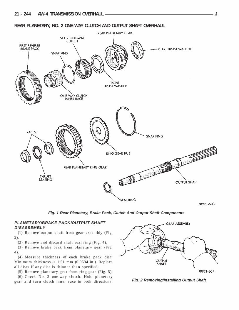
REAR PLANETARY, NO. 2 ONE-WAY CLUTCH AND OUTPUT SHAFT OVERHAUL
PLANETARY/BRAKE PACK/OUTPUT SHAFTDISASSEMBLY
(1) Remove output shaft from gear assembly (Fig.2).
(2) Remove and discard shaft seal ring (Fig. 4).(3) Remove brake pack from planetary gear (Fig.
4).(4) Measure thickness of each brake pack disc.
Minimum thickness is 1.51 mm (0.0594 in.). Replaceall discs if any disc is thinner than specified.
(5) Remove planetary gear from ring gear (Fig. 5).(6) Check No. 2 one-way clutch. Hold planetary
gear and turn clutch inner race in both directions.
Fig. 1 Rear Planetary, Brake Pack, Clutch And Output Shaft Components
Fig. 2 Removing/Installing Output Shaft
21 - 244 AW-4 TRANSMISSION OVERHAUL J

Race should turn freely counterclockwise, but lockwhen turned clockwise. Replace one-way clutch ifnecessary.
(7) Remove clutch inner race from planetary gear(Fig. 7).
(8) Remove clutch snap ring and remove No. 2 one-way clutch from planetary (Fig. 8).
(9) Remove front and rear thrust washers fromplanetary gear (Fig. 9).
(10) Remove thrust bearing and washers from ringgear (Fig. 10).
(11) Remove ring gear snap ring and remove ringgear hub (Fig. 11).
Fig. 3 Removing/Installing Shaft Seal Ring
Fig. 4 Removing/Installing First-Reverse Brake Pack
Fig. 5 Removing/Installing Rear Planetary
Fig. 6 Checking No. 2 One-Way Clutch Operation
Fig. 7 Removing/Installing Clutch Inner Race
J AW-4 TRANSMISSION OVERHAUL 21 - 245

(12) Inspect and replace any worn or damagedplanetary gear components.
ASSEMBLING REAR PLANETARY, BRAKEPACK, CLUTCH AND SHAFT
(1) Install hub and snap ring in ring gear (Fig. 11)(2) Identify ring gear thrust bearing and races by
following dimensions (Fig. 10):• Outer diameter of bottom race is 44.8 mm (1.764in.) and inner diameter is 27.6 mm (1.087 in.).• Outer diameter of bearing is 44.7 mm (1.760 in.)and inner diameter is 30.1 mm (1.185 in.).• Outer diameter of upper race is 44.8 mm (1.764in.) and inner diameter is 28.8 mm (1.134 in.).
(3) Lubricate ring gear thrust bearing and raceswith petroleum jelly and install them in ring gear(Fig. 10).
(4) Coat planetary thrust washers with petroleumjelly and install them in gear (Fig. 9).
(5) Install No. 2 one-way clutch in planetary gear.Be sure flanged side of clutch faces upward (Fig. 12).
(6) Install clutch retaining snap ring and installclutch inner race (Fig. 7). Turn race counterclockwiseto ease installation.
(7) Verify one-way clutch operation. Hold gear andturn inner race in both directions. Race should turnfreely counterclockwise, but lock when turned clock-wise.
(8) Install planetary gear in ring gear.
Fig. 8 Removing.Installing One-Way Clutch
Fig. 9 Removing/Installing Rear Planetary ThrustWashers
Fig. 10 Removing/Installing Ring Gear ThrustBearing And Races
21 - 246 AW-4 TRANSMISSION OVERHAUL J

(9) Assemble clutch discs and clutch plates (Fig. 4).Sequence is disc first, then a plate. Use seven discsand plates in a 6-cyl. transmission.
(10) Install brake pack on planetary gear (Fig. 4).(11) Install new seal ring on output shaft (Fig. 3).
Be sure ring ends are interlocked as shown.
(12) Set assembled components aside for final as-sembly.
FIRST-REVERSE BRAKE PISTON ANDTRANSMISSION CASE OVERHAUL
BRAKE DISASSEMBLY AND INSPECTION(1) Remove bearing and race assembly from trans-
mission case (Fig. 2).(2) Check first/reverse brake piston operation with
compressed air (Fig. 3). Piston should move smoothlyand not bind or stick. If piston operation is incorrect,case or piston may require replacement.
(3) Compress piston return springs with Tool 7539and remove piston snap ring (Fig. 4).
Fig. 12 Installing No. 2 One-Way Clutch
Fig. 1 First-Reverse Brake Pistons And Transmission Case
Fig. 11 Removing/Installing Ring Gear Hub
J AW-4 TRANSMISSION OVERHAUL 21 - 247

(4) Remove Tool 7539 and remove piston returnsprings.
(5) Remove No. 2 first-reverse brake piston withcompressed air. Apply air through same transmissionfeed hole used for checking piston operation.
(6) Remove reaction sleeve with Sleeve RemoverTool 7542 (Fig. 5). Insert tool flanges under sleeveand lift tool and sleeve out of case.
(7) Remove No. 1 first/reverse brake piston withPiston Puller 7543 (Fig. 6). Slip tool under piston andlift tool and piston out of case.
(8) Measure free length of piston return springswith springs mounted in retainer. Length should be18.382 mm (0.724 in.). Replace springs if length isless than this.
(9) Clean transmission case thoroughly with sol-vent and dry it with compressed air. Blow com-pressed air through oil feed passages to removesolvent residue and ensure that passages are clear.Inspect the case for wear or damage. Replace case ifnecessary.
ASSEMBLING FIRST/REVERSE BRAKEPISTON
(1) Lubricate and install new O-rings on No. 1first/reverse brake piston and on reaction sleeve (Fig.7). Then install piston in sleeve.
Fig. 2 Removing/Installing Bearing And RaceAssembly
Fig. 3 Checking First-Reverse Brake PistonOperation
Fig. 4 Removing/Installing Piston Snap Ring
Fig. 5 Removing/Installing Reaction Sleeve
21 - 248 AW-4 TRANSMISSION OVERHAUL J

(2) Lubricate and install new O-ring on No. 2brake piston.
(3) Install assembled No. 1 piston and reactionsleeve on No. 2 piston (Fig. 8).
(4) Lubricate and install piston assembly in case(Fig. 9). Align piston and case slots and press pistonassembly into case with hand pressure.
(5) Position piston return springs on No. 2 piston.(6) Compress piston return springs with Tool 7539
and install piston snap ring (Fig. 4). Be sure snapring end gap is not aligned with any tangs on returnspring retainer.
(7) Verify piston operation with compressed air asoutlined in disassembly procedure.
(8) Coat bearing and race assembly with petroleumjelly and install it in piston assembly (Fig. 2). Bear-ing and race assembly outer diameter is 57.7 mm(2.272 in.) and inner diameter is 39.2 mm (1.543 in.).
Fig. 6 Removing/Installing First-Reverse Brake No.1Piston
Fig. 7 Assembling No. 1 Piston And Sleeve
Fig. 8 Assembling First-Reverse Brake Pistons
Fig. 9 Installing First-Reverse Brake PistonAssembly
J AW-4 TRANSMISSION OVERHAUL 21 - 249

TRANSMISSION VALVE BODY OVERHAULThe valve body assembly consists of two sections
which are the upper body and lower body (Figures 1
and 2). Disassembly, inspection and overhaul proce-dures for each section are outlined separately. Referto the appropriate procedure as needed.
Fig. 1 Lower Body Components
21 - 250 AW-4 TRANSMISSION OVERHAUL J

Fig. 2 Upper Body Components
J AW-4 TRANSMISSION OVERHAUL 21 - 251

REMOVING UPPER BODY FROM LOWER BODY(1) Remove two-piece detent spring (Fig. 3). Note
position of spring sections for assembly reference.
(2) Remove manual valve from lower body (Fig. 4).(3) Remove bolts attaching upper body to lower
body (Fig. 5).(4) Carefully lift and remove upper body, plate and
gaskets from lower body (Fig. 6).(5) Disassemble and overhaul upper and lower
body sections as outlined in following procedures.
LOWER BODY DISASSEMBLY(1) Remove check valve and spring, pressure relief
valve and spring and ball check and seat from lowerbody. Note location of each valve for assembly refer-ence (Fig. 1).
Fig. 3 Removing/Installing Detent Spring
Fig. 4 Removing/Installing Manual Valve
Fig. 5 Valve Body Bolt Locations
Fig. 6 Upper Body, Plate And Gaskets
Fig. 1 Lower Body Check Valve And StrainerLocation
21 - 252 AW-4 TRANSMISSION OVERHAUL J

(2) Remove oil strainers (Fig. 2).(3) Note or mark position of valve retainers and
pressure reducing plug clip for assembly reference(Fig. 2). Do not remove the retainers at this time.
(4) Remove solenoid No. 1, 2 and 3. Discard sole-noid O-rings.
(5) Remove 1-2 shift valve retainer (Fig. 3).(6) Remove 1-2 shift valve plug, valve spring and
valve (Fig. 4).
(7) Remove primary regulator valve as follows:
WARNING: THE PRIMARY REGULATOR VALVESLEEVE AND PLUNGER ARE UNDER TENSIONFROM THE VALVE SPRING. EXERT COUNTER-PRESSURE ON THE SPRING WHILE REMOVINGTHE VALVE RETAINER TO PREVENT COMPONENTSFROM FLYING OUT.
(a) Note position of valve retainer for assemblyreference (Fig. 5). Then press valve sleeve inwardwith your thumb and remove retainer with magnet.
(b) Slowly release thumb pressure on sleeve andremove sleeve, spring and washer and valve (Fig.6). Use magnet to remove valve if necessary.(8) Remove regulator valve plunger from sleeve
(Fig. 7).(9) Remove retaining clip and remove pressure re-
ducing plug (Fig. 8). Cover screwdriver blade withtape to avoid scratching valve body surface.
(10) Remove accumulator control valve retainerand remove control valve assembly (Fig. 9).
(11) Remove spring and control valve from valvesleeve (Fig. 10).
(12) Clean lower body valve components with sol-vent and dry them with compressed air only. Do not
Fig. 2 Valve Retainer And Clip Location
Fig. 3 Removing 1-2 Shift Valve Retainer
Fig. 4 Removing/Installing 1-2 Shift Valve
Fig. 5 Regulator Valve Retainer Position
J AW-4 TRANSMISSION OVERHAUL 21 - 253

use shop towels or rags. Lint or foreign material fromtowels or rags can interfere with valve operation.
(13) Inspect condition of lower body components.Replace lower body if any bores are scored or cor-roded. Replace valves, plugs or sleeves that arescored or worn. Replace oil strainers if cut, torn ordamaged in any way.
(14) Inspect valve body springs. Replace any springhaving rusted, distorted, or collapsed coils. Measurelength of each valve body spring. Replace any springif free length is less than length specified in followingchart (Fig. 11).
LOWER BODY ASSEMBLY(1) Lubricate lower body components with auto-
matic transmission fluid.(2) Install spring and accumulator control valve in
sleeve (Fig. 11). Then install assembled componentsin lower body (Fig. 9).
(3) Press accumulator control valve assembly intovalve bore and install retainer (Fig. 9).
(4) Install pressure reducing plug in plug bore.Then secure plug with retaining clip (Fig. 8).
(5) Install washer on primary regulator valveplunger (Fig. 12).
(6) Install primary regulator valve plunger in valvesleeve (Fig. 7).
(7) Install valve spring and regulator valve sleeveand plunger.
(8) Press regulator valve sleeve into bore and in-stall retainer (Fig. 5 and 6). Be sure retainer is posi-tioned in sleeve lugs as shown.
(9) Install 1-2 shift valve, spring and plug (Fig. 4).Then press valve assembly into bore and install re-tainer.
(10) Install replacement O-rings on solenoids andinstall solenoids on valve body. Tighten solenoid at-taching bolts to 10 Nzm (7 ft-lbs) torque.
(11) Install oil strainers (Fig. 13). Identify strain-ers before installation. The three strainers areall the same diameter but are different lengths.Two strainers are 11.0 mm (0.443 in.) long whileone strainer is 19.5 mm (0.76 in.) long (Fig. 14).
(12) Install check valve and spring (Fig. 13).(13) Install check ball and seat (Fig. 13).(14) Install pressure relief valve and spring (Fig.
13).
Fig. 6 Removing/Installing Primary PressureRegulator Valve
Fig. 7 Removing/Installing Regulator Valve Plunger
Fig. 8 Removing/Installing Pressure Reducing Plug
21 - 254 AW-4 TRANSMISSION OVERHAUL J

Fig. 10 Accumulator Control Valve Components
Fig. 11 Lower Body Valve Spring Dimensions
Fig. 9 Removing/Installing Accumulator ControlValve Assembly
J AW-4 TRANSMISSION OVERHAUL 21 - 255

UPPER BODY DISASSEMBLY ANDINSPECTION
(1) Remove valve body plate and gaskets (Fig. 1).Discard gaskets.
(2) Remove strainer and eight check balls (Fig. 2).Note check ball and strainer position for assemblyreference.
Fig. 12 Installing Washer On Regulator ValvePlunger
Fig. 13 Oil Strainer And Check Valve Installation
Fig. 1 Removing/Installing Upper Body Plate AndGaskets
Fig. 2 Check Ball And Strainer Location/Identification
21 - 256 AW-4 TRANSMISSION OVERHAUL J

(3) Remove valve stop and throttle cam (Fig. 3). (4) Remove throttle valve pin with magnet and removedownshift plug, valve spring and throttle valve (Fig. 4).
(5) Turn upper body over and remove throttlevalve adjusting rings and spring (Fig. 5). Note num-ber of adjusting rings if valve is equipped with them.
(6) Remove 3-4 shift valve retainer with magnet andremove valve plug, spring and 3-4 shift valve (Fig. 6).Fig. 3 Removing/Installing Valve Stop And Throttle Cam
Fig. 4 Removing/Installing Throttle Valve Fig. 6 Removing/Installing 3-4 Shift Valve
Fig. 5 Throttle Valve Adjusting Ring Location (If Equipped)
J AW-4 TRANSMISSION OVERHAUL 21 - 257

(7) Remove second coast modulator valve retainerand remove valve plug, spring and valve.
(8) Remove lock-up relay valve retainer and re-move relay valve and sleeve assembly (Fig. 8).
(9) Remove relay valve, spring and plunger fromvalve sleeve (Fig. 9).
(10) Remove secondary pressure regulator valve re-tainer and remove plug, regulator valve and spring(Fig. 10).
(11) Remove cut-back valve retainer and removeplug, cut-back valve and spring (Fig. 11).
(12) Remove 2-3 shift valve retainer and removeplug, spring and 2-3 shift valve (Fig. 12).
(13) Remove low coast modulator valve retainerand remove valve plug, spring and low coast modula-tor valve (Fig. 13).
(14) Clean the upper body components with solventand dry them with compressed air only. Do not useshop towels or rags. Lint or foreign material fromtowels or rags can interfere with valve operation.
(15) Inspect condition of the upper body compo-nents. Replace the upper body if any of the bores arescored or corroded. Replace any valves, plugs orsleeves if scored or worn. Replace the oil strainer ifcut, torn or damaged in any way.
Fig. 7 Removing/Installing Second Coast ModulatorValve
Fig. 8 Removing/Installing Converter Clutch RelayValve
Fig. 9 Relay Valve Components
21 - 258 AW-4 TRANSMISSION OVERHAUL J

Fig. 10 Removing/Installing Secondary PressureRegulator Valve
Fig. 11 Removing/Installing Cut-Back Valve
Fig. 12 Removing/Installing 2-3 Shift Valve
Fig. 13 Removing/Installing Low Coast ModulatorValve
J AW-4 TRANSMISSION OVERHAUL 21 - 259

(16) Inspect the valve body springs. Replace anyspring having rusted, distorted, or collapsed coils-.Measure length of each spring. Replace any spring iffree length is less than specified in the chart (Fig.14).
UPPER BODY ASSEMBLY(1) Lubricate the valves, springs, plugs, sleeves
and the valve bores in the upper body with automatictransmission fluid.
(2) Note position of the valve retainers (A) andstop (B) for assembly reference (Fig. 15).
(3) Install low coast modulator valve, spring andplug in valve bore. Press valve plug inward and in-stall retainer (Fig. 13).
(4) Install 2-3 shift valve, spring and plug in valvebore. Press plug inward and install retainer (Fig. 12).
(5) Install cut-back valve spring, valve and plug(Fig. 11). Press plug inward and install retainer.
(6) Install secondary regulator valve spring, valveand plug in valve bore. Press plug inward and installretainer (Fig. 10).
(7) Assemble lock-up relay valve. Install springand plunger in valve sleeve (Fig. 9). Then install as-sembled valve in sleeve.
(8) Install assembled lock-up relay valve in valvebore and install retainer (Fig. 8).
(9) Install second coast modulator valve, springand plug in valve bore. Press plug inward and installretainer (Fig. 7).
(10) Install 3-4 shift valve, spring and plug in bore.Press plug inward and install retainer (Fig. 6).
Fig. 14 Upper Body Spring/Valve Identification
21 - 260 AW-4 TRANSMISSION OVERHAUL J

(11) Install throttle valve in valve bore. Push valveinto place and install valve stop (Fig. 16).
(12) On models with adjusting rings, turn upperbody over and install adjusting rings (Fig. 17). Besure to install same number of rings as were re-moved.
(13) Install throttle valve adjusting spring in boreand onto end of throttle valve (Fig. 18).
(14) Install downshift spring and plug in throttlevalve bore. Press plug inward against throttle valveand spring and install retainer pin (Fig. 19).
(15) Install sleeve in throttle cam (Fig. 20).
(16) Install spring on cam (Fig. 20). Hook curvedend of spring through hole in cam as shown.
(17) Mount cam on upper body and install cam at-taching bolt and spacer (Fig. 20). Tighten bolt to 10Nzm (7 ft. lbs.) torque.
(18) Be sure straight end of spring is seated in up-per body slot as shown (Fig. 20).
(19) Install check balls in upper body (Fig. 2).(20) Install oil strainer (Fig. 2).
INSTALLING UPPER BODY ON LOWER BODYIf valve body was equipped with gaskets, start at
step (1). However, if valve body is not equipped withgaskets, start at step (4).
(1) Position new No. 1 gasket (Fig. 1) on upperbody.
(2) Position valve body plate on No. 1 gasket.
Fig. 15 Valve Retainer And Stop Locations
Fig. 16 Installing Throttle Valve And Stop
Fig. 17 Install Throttle Valve Adjusting Rings (IfEquipped)
Fig. 18 Installing Throttle Valve Adjusting Spring
J AW-4 TRANSMISSION OVERHAUL 21 - 261

(3) Position new No. 2 gasket (Fig. 2) on valvebody plate and align gaskets and plate using boltholes as guides.
(4) Install valve body bolts. Three differentlength bolts are used. Refer to the Figure 3 forbolt locations. Chart symbols indicate bolt loca-tion and length in millimeters.
(5) Tighten valve body bolts to 6.4 Nzm (56 in. lbs.)torque.
Fig. 19 Installing Downshift Plug
Fig. 20 Installing Throttle Cam
Fig. 1 Valve Body Gasket No. 1
Fig. 2 Valve Body Gasket No. 2
Fig. 3 Valve Body Bolt Location/Size
21 - 262 AW-4 TRANSMISSION OVERHAUL J

(6) Install manual valve (Fig. 4).(7) Install two-piece detent spring (Fig. 5). Tighten
spring attaching bolt to 10 Nzm (7 ft. lbs.) torque.
Fig. 4 Installing Manual ValveFig. 5 Installing Detent Spring
J AW-4 TRANSMISSION OVERHAUL 21 - 263

Fig. 1 AW-4 Transmission Components
21 - 264 AW-4 TRANSMISSION OVERHAUL J

TRANSMISSION ASSEMBLY AND ADJUSTMENT(1) During assembly, lubricate components with
transmission fluid or petroleum jelly as indicated.(2) If any of the transmission components are still
assembled after overhaul checking procedures, disas-semble as necessary in preparation for transmissionassembly.
(3) Verify thrust bearing and race installation dur-ing assembly. Refer to the Thrust Bearing Chart (Fig.2) for bearing and race location and correct position-ing.
(4) Install rear planetary gear, second brake drumand output shaft as outlined in following steps:
(5) Verify No. 10 thrust bearing and race (Fig. 2).Bearing and race outer diameter is 57.7 mm (2.272in.) and inside diameter is 39.2 mm (1.543 in.).
(6) Coat thrust bearing and race assembly with pe-troleum jelly and install in case (Fig. 3). Race facesdown. Bearing rollers face up.
Fig. 2 Thrust Bearing Chart
Fig. 3 Installing Thrust Bearing And Race (No. 10)
J AW-4 TRANSMISSION OVERHAUL 21 - 265

(7) Align teeth of second brake drum and clutchpack (Fig. 4).
(8) Align rear planetary-output shaft assemblyteeth with case slots and install assembly in case(Fig. 5).
(9) Install rear planetary snap ring with snap ringpliers. Chamfered side of snap ring faces up and to-ward case front (Fig. 6).
(10) Check first-reverse brake pack clearance withfeeler gauge. Clearance should be 0.70 - 1.20 mm(0.028 - 0.047 in.). If clearance is incorrect, planetaryassembly, thrust bearing or snap ring is not properlyseated in case. Remove and reinstall components ifnecessary.
Fig. 4 Aligning Second Brake Drum And ClutchPack Teeth
Fig. 5 Installing Output Shaft And Rear PlanetaryAssembly
Fig. 6 Installing Planetary Snap Ring
Fig. 7 Checking First-Reverse Brake Pack Clearance
21 - 266 AW-4 TRANSMISSION OVERHAUL J

(11) Install second brake piston sleeve (Fig. 8).Sleeve lip faces up and toward case front as shown.
(12) Install second brake drum gasket with In-staller Tool 7544 (Fig. 9). Gasket depth is 43.7 mm(1.720 in.).
(13) Install park lock pawl, spring and pin (Fig.10).
(14) Connect park lock rod to manual valve shiftsector (Fig. 11).
Fig. 8 Installing Second Brake piston Sleeve
Fig. 9 Installing Second Brake Drum Gasket
Fig. 10 Installing Park Lock Pin, Spring And Pawl
Fig. 11 Installing Park Lock Rod
J AW-4 TRANSMISSION OVERHAUL 21 - 267

(15) Position park lock rod bracket on case andtighten bracket attaching bolts to 10 Nzm (7 ft. lbs.)torque (Fig. 12).
(16) Verify park lock operation. Move shift sectorto Park position. Park pawl should be firmly engaged(locked) in planetary ring gear (Fig. 13).
(17) Install No. 1 one-way clutch (Fig. 14). Shortflanged side of clutch faces up and toward case front.
(18) Install second brake pack (Fig. 15). Installdisc then plate. Continue installation sequence untilcorrect number of discs-plates are installed. Use fivediscs and five plates.
(19) Install second brake pack retainer withrounded edge of retainer facing disc.
(20) Install second brake pack snap ring.
Fig. 12 Installing Park Rod Bracket
Fig. 13 Checking Park Pawl Engagement
Fig. 14 Installing No. 1 One-Way Clutch
Fig. 15 Installing Second Brake Pack
21 - 268 AW-4 TRANSMISSION OVERHAUL J

(21) Check brake pack clearance with feeler gauge(Fig. 16). Clearance should be 0.062 - 1.98 mm (0.024- 0.078 in.). If brake pack clearance is not correct,brake pack components are not seated. Reassemblebrake pack if necessary.
(22) Install planetary sun gear and input drum(Fig. 17). Be sure drum thrust washer tabs areseated in drum. Use petroleum jelly to hold thrustwasher in position if necessary.
(23) Install front planetary gear on sun gear (Fig.18).
(24) Support output shaft with wood blocks (Fig.19).
Fig. 16 Checking Second Brake Pack Clearance
Fig. 17 Installing Sun Gear And Input Drum
Fig. 18 Installing Front Planetary Gear
Fig. 19 Supporting Output Shaft
J AW-4 TRANSMISSION OVERHAUL 21 - 269

(25) Install planetary snap ring on sun gear withsnap ring plier tool 7541 (Fig. 20).
(26) Install tabbed thrust race on front planetarygear (Fig. 21). Washer tabs face down and towardgear. Race outer diameter is 47.8 mm (1.882 in.). In-side diameter is 34.3 mm (1.350 in.).
(27) Install second coast brake band (Fig. 22).(28) Install pin in second coast brake band. Then
install retaining ring on pin (Fig. 23).(29) Install thrust bearing and race in forward-di-
rect clutch (Fig. 24). Coat bearing/race with petro-leum jelly to hold them in place.
Fig. 22 Installing Second Coast Brake Band
Fig. 23 Installing Second Coast Brake Band Retaining Pin
Fig. 20 Installing Front Planetary Snap Ring
Fig. 21 Installing Planetary Thrust Race
21 - 270 AW-4 TRANSMISSION OVERHAUL J

(30) Verify forward-direct clutch thrust bearingsize.• Race outer diameter is 48.9 mm (1.925 in.) and in-side diameter is 26.0 mm (1.024 in.).• Bearing outer diameter is 46.7 mm (1.839 in.) andinside diameter is 26.0 mm (1.024 in.).
(31) Coat front planetary ring gear race with pe-troleum jelly and install it in ring gear (Fig. 25).
(32) Verify ring gear race size. Outer diameter is47.0 mm (1.850 in.) and inside diameter is 26.5 mm(1.045 in.).
(33) Align forward-direct clutch disc splines withscrewdriver (Fig. 26).
(34) Align and install front planetary ring gear inforward-direct clutch (Fig. 27).
(35) Coat bearing and race with petroleum jellyand install them in ring gear (Fig. 28). Verify bear-ing/race size.• Bearing outer diameter is 47.7 mm (1.878 in.) andinside diameter is 32.6 mm (1.283 in.).• Race outer diameter is 53.6 mm (2.110 in.) and in-side diameter is 30.6 mm (1.205 in.).
(36) Rotate front of transmission case downward
and install assembled planetary gear/forward-directclutch (Fig. 29).
(37) Check clearance between sun gear input drumand direct clutch drum (Fig. 30). Clearance should be9.8 - 11.8 mm (0.386 - 0.465 in.). If clearance is in-correct, planetary gear/forward-direct clutch assem-bly is not seated or is improperly assembled. Remove,and correct if necessary.
(38) Coat thrust bearing and race assembly withpetroleum jelly and install it on clutch shaft. Bearingfaces up and toward case front as shown (Fig. 31).
Fig. 24 Installing Forward-Direct Clutch ThrustBearing And Race
Fig. 25 Installing Planetary Ring Gear Race
Fig. 26 Aligning Forward-Direct Clutch Splines
Fig. 27 Installing Front Planetary Ring Gear
J AW-4 TRANSMISSION OVERHAUL 21 - 271

Verify bearing/race size. Bearing and race outer di-ameter is 47.8 mm (1.882 in.) and inside diameter is33.6 mm (1.301 in.).
(39) Assemble second coast brake piston compo-nents (Fig. 32).
(40) Install assembled second coast brake piston incase.
(41) Install replacement seals on second coastbrake piston cover and install cover in case.
(42) Install second coast brake piston snap ringwith snap ring plier tool (Fig. 33).
(43) Check second coast brake piston stroke as fol-lows:
(a) Make reference mark on brake piston rod(Fig. 34).
(b) Apply 57-114 psi air pressure through feedhole (Fig. 34). Alternately apply and release airpressure to operate piston.
(c) Check stroke with gauge 7552 (Fig. 35).(d) If stroke length is incorrect, piston, cover or
snap ring is not seated. Reassemble and checkstroke again if necessary.(44) Coat thrust race and tabbed washer with pe-
troleum jelly and install them on overdrive support(Fig. 36). Verify race size. Race outer diameter is 50.9mm (2.004 in.) and inside diameter is 36.2 mm (1.426in.).
Fig. 28 Installing Ring Gear Bearing And Race
Fig. 29 Installing Front Planetary And Forward-Direct Clutch Assembly
Fig. 30 Checking Input Drum-To-Direct Clutch DrumClearance
Fig. 31 Installing Clutch Shaft Thrust Bearing AndRace Assembly
21 - 272 AW-4 TRANSMISSION OVERHAUL J

Fig. 32 Assembling Second Coast Brake Piston
Fig. 33 Installing Second Coast Brake Piston SnapRing
Fig. 34 Marking Brake Piston Rod
Fig. 35 Checking Second Coast Brake Piston Stroke
Fig. 36 Installing Overdrive Support Thrust RaceAnd Washer
J AW-4 TRANSMISSION OVERHAUL 21 - 273

(45) Install overdrive support in case. Use two longbolts to help align and guide support into position(Fig. 37).
(46) Install overdrive support snap ring with SnapRing Plier Tool 7540 (Fig. 38). Chamfered side ofsnap ring faces up and toward case front. Snap ringends must be aligned with case opening withring ends approximately 24 mm (0.94 in.) fromcenterline of case opening.
(47) Install and tighten overdrive support bolts to25 Nzm (19 ft-lbs) torque (Fig. 39).
(48) Check output shaft end play with dial indica-tor (Fig. 40). End play should be 0.27 - 0.86 mm(0.0106 - 0.0339 in.).
(49) If output shaft end play is incorrect, one ormore of installed components is not seated. Reassem-ble as necessary and check end play again.
Fig. 37 Installing Overdrive Support
Fig. 38 Installing Overdrive Support Snap Ring
Fig. 39 Installing Overdrive Support Bolts
Fig. 40 Checking Output Shaft End Play
21 - 274 AW-4 TRANSMISSION OVERHAUL J

(50) Install overdrive brake clutch pack (Fig. 41). In-stall thickest plate first. Rounded edge of plate facesup. Install first disc followed by another plate untilfour discs and three plates are installed.
(51) Install stepped ring retainer plate with flatside facing disc. Then install brake pack snap ring(Fig. 42).
(52) Check overdrive brake piston stroke as fol-lows:
(a) Mount Gauge 7546 in dial indicator and posi-tion gauge tool against overdrive brake piston (Fig.43).
(b) Apply and release overdrive brake pistonwith compressed air and note piston stroke lengthon dial indicator. Apply air pressure through feedhole in case (Fig. 44).
(c) Piston stroke length should be 1.40 - 1.70 mm(0.55 - 0.66 in.).
(d) If stroke is incorrect, brake pack or piston isinstalled incorrectly. Check and correct as neces-sary and measure piston stroke again.(53) Remove dial indicator and gauge tool.(54) Remove overdrive brake piston snap ring and
remove overdrive clutch pack components.(55) Coat overdrive lower race, thrust bearing and
upper race with petroleum jelly and install them inoverdrive support (Fig. 45). Be sure races and bear-ing are assembled and installed as shown.
(56) Verify bearing/race sizes before proceeding.Bearing-race sizes are:
Fig. 41 Installing Overdrive Brake Clutch Pack
Fig. 42 installing Overdrive Brake Snap Ring
Fig. 43 Positioning Gauge Tool And Dial Indicator
Fig. 44 Checking Overdrive Brake Piston Stroke
J AW-4 TRANSMISSION OVERHAUL 21 - 275

• Outer diameter of lower race is 47.8 mm (1.882in.) and inside diameter is 34.3 mm (1.350 in.).• Outer diameter of bearing is 47.7 mm (1.878 in.)and inside diameter is 32.7 mm (1.287 in.).• Outer diameter of upper race is 47.8 mm (1.882in.) and inside diameter is 30.7 mm (1.209 in.).
(57) Install overdrive planetary ring gear in sup-port (Fig. 46).
(58) Coat ring gear thrust race and thrust bearingassembly with petroleum jelly and install them ingear (Fig. 47).
(59) Verify bearing/race size before proceeding.
• Outer diameter of ring gear race-bearing is 47.8mm (1.882 in.) and inside diameter is 24.2 mm (0.953in.).• Outer diameter of bearing is 46.8 mm (1.844 in.)and inside diameter is 26.0 mm (1.024 in.).
(60) Coat tabbed thrust race with petroleum jellyand install it on planetary gear (Fig. 48). Race outerdiameter is 41.8 mm (1.646 in.) and inside diameteris 27.1 mm (1.067 in.).
(61) Install assembled overdrive planetary gearand clutch (Fig. 49).
(62) Coat thrust bearing and race assembly withpetroleum jelly and install it on clutch input shaft(Fig. 50). Bearing and race outer diameter is 50.2mm (1.976 in.) and inside diameter is 28.9 mm (1.138in.).
(63) Install overdrive brake pack as follows:
Fig. 45 Installing Overdrive Support Thrust BearingAnd Races
Fig. 46 Installing Overdrive Planetary Ring Gear
Fig. 47 Installing Ring Gear Thrust Bearing AndRace
Fig. 48 Installing Planetary thrust Race
21 - 276 AW-4 TRANSMISSION OVERHAUL J

(a) Install 4.0 mm (0.157 in.) thick plate first.Rounded edge of plate must face upward.
(b) Install a disc followed by a plate until the re-quired number of discs and plates are installed. Besure to install the stepped plate last with the flatside of the plate facing the disc (Fig. 51).
(c) Confirm that four discs and three plates havebeen installed.(64) Install clutch pack snap ring (Fig. 52).
(65) Coat thrust bearing race with petroleum jellyand install it in oil pump (Fig. 53). Bearing raceouter diameter is 47.2 mm (1.858 in.) and inside di-ameter is 28.1 mm (1.106 in.).
(66) Lubricate and install replacement O-ring onoil pump body.
(67) Install oil pump in case. Align pump and casebolt holes and carefully ease pump into place (Fig.54).
CAUTION: Do not use force to seat the pump. Theseal rings on the stator shaft could be damaged ifthey bind or stick to the direct clutch drum.
(68) Tighten oil pump bolts to 22 Nzm (16 ft. lbs.)torque.
Fig. 49 Installing Overdrive Planetary And ClutchAssembly
Fig. 50 Installing Input Shaft Thrust Bearing AndRace Assembly
Fig. 51 Installing Overdrive Clutch Pack
Fig. 52 Installing Clutch Pack Snap Ring
J AW-4 TRANSMISSION OVERHAUL 21 - 277

(69) Verify input shaft rotation. Shaft should rotatesmoothly and not bind.
(70) Lubricate and install new O-ring on transmis-sion throttle cable adapter and install cable in case(Fig. 55).
(71) Check clutch and brake operation. Operateclutches and brakes with compressed air appliedthrough feed holes in case (Fig. 56). Listen for clutchand brake application. If you do not hear a clutch orbrake apply, disassemble transmission and repairfault before proceeding. It is necessary to blockthe overdrive clutch accumulator feed hole No.8 (Fig. 56) in order to check direct clutch oper-ation.
(72) Lubricate and install new O-rings on accumu-lator pistons (Fig. 57).
Fig. 53 Installing Oil Pump Thrust Race
Fig. 54 Installing Oil Pump
Fig. 55 Installing Transmission Throttle Cable
Fig. 56 Clutch And Brake Feed Hole Locations
21 - 278 AW-4 TRANSMISSION OVERHAUL J

(73) Assemble and install accumulator pistons andsprings (Fig. 57).
(74) Install new check ball body and spring (Fig.58).
(75) Position valve body on case (Fig. 59).
(76) Install detent spring (Fig. 59).(77) Align manual valve, detent spring and shift
sector (Fig. 59).
(78) Connect transmission throttle cable to throttlevalve cam (Fig. 60).
(79) Install and tighten valve body-to-case bolts to10 Nzm (7 ft. lbs.) torque.
(80) Connect valve body solenoid wires to solenoids(Fig. 61).
(81) Install new O-ring on solenoid harnessadapter and secure adapter to case.
(82) Install valve body oil tubes (Fig. 62). Taptubes into place with a plastic mallet. Be sure theflanged tube ends and straight tube ends are in-stalled as shown.
Fig. 57 Accumulator Piston And Spring Installation
Fig. 58 Installing Check Ball Body And Spring
Fig. 59 Aligning Manual Valve, Shift Sector AndDetent Spring
Fig. 60 Connecting Transmission Throttle Cable
J AW-4 TRANSMISSION OVERHAUL 21 - 279

(83) Install new gaskets on oil screen and installscreen on valve body. Tighten screen bolts to 10 Nzm(7 ft. lbs.) torque.
(84) Install magnet in oil pan. Be sure magnetdoes not interfere with valve body oil tubes.
(85) Apply Loctite 599 to sealing surface of oil pan.Sealer bead should be at least 3 mm (1/8 in.) wide.Install pan on case and tighten pan bolts to 7 Nzm(65 in. lbs.) torque.
(86) Install transmission speed sensor rotor andkey on output shaft (Fig. 63).
(87) Install spacer and speedometer drive gear onoutput shaft. Then install retaining snap ring (Fig.64).
(88) Apply bead of Loctite 599 sealer to sealingsurface at rear of case (Fig. 65).
(89) Install adapter housing on transmission.Tighten adapter bolts to 34 Nzm (25 ft. lbs.) torque.
(90) Install transmission speed sensor (Fig. 66).Tighten sensor bolt to 7.4 Nzm (65 in. lbs.) torqueand connect sensor wire harness connector.
(91) Install converter housing (Fig. 67). Tighten 12mm diameter housing bolts to 57 Nzm (42 ft. lbs.)torque. Tighten 10 mm diameter housing bolts to 34Nzm (25 ft. lbs.) torque.
(92) Install transmission shift lever on manualvalve shaft. Do not install lever attaching nut at thistime.
(93) Move transmission shift lever fully rearward.Then move lever two detent positions forward.
Fig. 61 Connecting Valve Body Solenoid Wires
Fig. 62 Installing Valve Body Oil Tubes
Fig. 63 Installing Transmission Speed Sensor RotorAnd Key
Fig. 64 Installing Spacer And Speedometer DriveGear
21 - 280 AW-4 TRANSMISSION OVERHAUL J

(94) Mount park/neutral position switch on manualvalve shaft and tighten switch adjusting bolt justenough to keep switch from moving (Fig. 68).
(95) Install park/neutral position switch tabbedwasher and retaining nut (Fig. 68). Tighten nut to6.9 Nzm (61 in. lbs.) torque, but do not bend any ofthe washer tabs against the nut at this time.
(96) Align park/neutral position switch standardline with groove or flat on manual shaft (Fig. 68).
(97) Tighten park/neutral position switch adjustingbolt to 13 Nzm (9 ft. lbs.) torque.
(98) Install transmission shift lever on manualvalve shaft. Tighten lever attaching nut to 16 Nzm(12 ft. lbs.) torque.
Fig. 65 Applying Sealer To Case Rear Flange
Fig. 66 Installing Transmission Speed Sensor
Fig. 67 Installing Converter Housing
Fig. 68 Park/Neutral Position Switch Installation/Adjustment
J AW-4 TRANSMISSION OVERHAUL 21 - 281

(99) Install retaining clamp for wire harness andthrottle cable (Fig. 69).
(100) Install torque converter.(101) Verify that converter is seated by measuring
distance between converter housing flange and one ofthe converter mounting pads (Fig. 70). Use straight-edge and vernier calipers to measure distance. On6-cyl. transmissions, distance should be 16.5 mm(0.650 in.).
(102) Secure converter in transmission withC-clamp or metal strapping. Do this before mountingtransmission on jack or moving transmission undervehicle.
(103) Install lower half of transmission fill tube (in-stall upper half after transmission is in vehicle).
CAUTION: The transmission cooler and lines mustbe reverse flushed if overhaul corrected a malfunc-tion that generated sludge, metal particles, orclutch friction material. The torque converter shouldalso be replaced if contaminated by the same mal-function. Debris and residue not flushed from thecooler and lines will flow back into the transmissionand converter. The result will be a repeat failure andshop comeback.
Fig. 69 Installing Cable/Harness ClampsFig. 70 Checking Converter Installation
21 - 282 AW-4 TRANSMISSION OVERHAUL J

NP231 TRANSFER CASE
INDEX
page page
General Information . . . . . . . . . . . . . . . . . . . . . . . 283Overhaul Cleaning and Inspection . . . . . . . . . . . . 294Shift Lever Installation (XJ) . . . . . . . . . . . . . . . . . 286Shift Lever Installation (YJ) . . . . . . . . . . . . . . . . . 286Shift Lever Removal (XJ) . . . . . . . . . . . . . . . . . . . 286Shift Lever Removal (YJ) . . . . . . . . . . . . . . . . . . . 286Shift Linkage Adjustment . . . . . . . . . . . . . . . . . . . 286
Speedometer Service . . . . . . . . . . . . . . . . . . . . . 287Transfer Case Assembly . . . . . . . . . . . . . . . . . . . 294Transfer Case Disassembly and Overhaul . . . . . . 289Transfer Case Identification . . . . . . . . . . . . . . . . . 284Transfer Case Installation . . . . . . . . . . . . . . . . . . 288Transfer Case Lubricant and Fill Level . . . . . . . . . 284Transfer Case Removal . . . . . . . . . . . . . . . . . . . . 287
GENERAL INFORMATIONThe NP231 is a part-time transfer case with a low
range reduction gear system (Fig. 1). The NP231 hasthree operating ranges plus a Neutral position. A lowrange system provides a reduction ratio for increasedlow speed torque capability.
The NP231 is the Command Trac transfer case. Itis used in XJ and YJ models. Two versions are used.One version retains the synchronizer componentsused in previous models. A newly introduced versionis not equipped with synchro components.
Fig. 1 NP231 Transfer Case
J NP231 TRANSFER CASE 21 - 283

OPERATING RANGESNP231 operating ranges are: 2-wheel drive high;
4-wheel drive high and 4-wheel drive low.2-wheel drive range is for use on all road surfaces.
The 4-wheel drive high and low ranges are undiffer-entiated and should only be used on unpaved, lowtraction surfaces only. The only exception being whenhard surface roads are snow and ice covered.
SHIFT MECHANISMOperating ranges are selected with a floor mounted
shift lever. The shift lever is connected to the trans-fer case range lever by an adjustable linkage rod. Astraight line shift pattern is used. Range positionsare marked on the shifter bezel cover plate, or on theshift knob.
TRANSFER CASE IDENTIFICATIONA circular ID tag is attached to the rear case of
each NP231 transfer case (Fig. 2). The ID tag pro-vides the transfer case model number, assemblynumber, serial number and low range ratio.
The transfer case serial number also represents thedate of build. For example, a serial number of7-10-94 would represent July 10, 1994.
TRANSFER CASE LUBRICANT AND FILL LEVELRecommended lubricant for the NP231 transfer
case is Mopar Dexron II.Approximate lubricant refill capacity is 1.54 liters
(3.25 pints) for YJ and 1.04 liters (2.2 pints) for XJ.Correct fill level is to the bottom edge of the fill
plug hole. Be sure the vehicle is level to ensure anaccurate fluid level check.
Fig. 2 Transfer Case Identification Tag
21 - 284 NP231 TRANSFER CASE J

NP231 SERVICE DIAGNOSIS
J NP231 TRANSFER CASE 21 - 285

SHIFT LINKAGE ADJUSTMENT(1) Shift transfer case into 4L position.(2) Raise vehicle.(3) Loosen lock bolt on adjusting trunnion (Figs. 3
and 4).4) Be sure linkage rod slides freely in trunnion.
Clean rod and apply spray lube if necessary.(5) Verify that transfer case range lever is fully en-
gaged in 4L position.(6) Tighten adjusting trunnion lock bolt.(7) Lower vehicle.
SHIFT LEVER REMOVAL (XJ)(1) Shift transfer case into 4L.(2) Raise vehicle.(3) Loosen adjusting trunnion locknut and slide
shift rod out of trunnion (Fig. 4). If rod lacks enoughtravel to come out of trunnion, push trunnion out oftorque shaft.
(4) Lower vehicle.(5) Remove console. Refer to park brake section in
Group 5 for procedures.(6) Remove screws attaching lever assembly to
floorpan and remove assembly and shift rod (if leftattached).
SHIFT LEVER INSTALLATION (XJ)(1) If shift rod was not removed from lever assem-
bly, work rod down through floorpan opening. Thenposition lever assembly on floorpan and install as-sembly attaching screws.
(2) Install console.(3) Raise vehicle.(4) Connect trunnion to torque shaft arm. Or, slide
shift rod into trunnion on range lever. Be sure shiftrod slides freely in trunnion.
(5) Verify that range lever is in 4L position. Thentighten trunnion lock bolt.
(6) Lower vehicle and check transfer case shift op-eration.
SHIFT LEVER REMOVAL (YJ)(1) Shift transfer case into neutral.(2) Remove shift lever knob and retaining nut.
Then remove shift lever boot and bezel.(3) Raise vehicle(4) Loosen lock bolt in adjusting trunnion and slide
shift rod out of trunnion (Fig. 3).(5) Remove bolts/nuts attaching bracket and brace
assembly to transmission (Fig. 5).(6) Remove shift lever and bracket as assembly.(7) YJ shift lever assembly is serviceable. If any
assembly part must be replaced, remove pivot bolt,lever pin E-clip, and lever pin and spring. Then dis-assemble and replace necessary part (Fig. 6).
SHIFT LEVER INSTALLATION (YJ)(1) Assemble lever components, if necessary. Lube
pivot bolt and pin with Mopar multi-mileage greasebefore installation.
(2) Work shift lever upward into vehicle interior.Then position lever and bracket assembly on trans-mission and install attaching bolts/nuts.
(3) Place transfer case range lever in 4L position.Then slide shift rod into trunnion and tighten lockbolt.
Fig. 3 Adjusting Trunnion And Lock Bolt (YJ)
Fig. 4 Shift Linkage (XJ)
21 - 286 NP231 TRANSFER CASE J

(4) Lower vehicle.(5) Install shift lever bezel and boot (Fig. 7). Then
install retaining nut and shift knob on lever.
SPEEDOMETER SERVICESpeedometer service is covered in the 30RH/32RH,
or AW-4 automatic transmission sections in thisgroup. Refer to the appropriate section as needed.
TRANSFER CASE REMOVAL(1) Shift transfer case into Neutral.(2) Raise vehicle.(3) Drain transfer case lubricant.(4) Mark front and rear propeller shaft yokes for
alignment reference.(5) Support transmission with jack stand.(6) Remove rear crossmember, or skid plate.(7) Disconnect front/rear propeller shafts at trans-
fer case.(8) Disconnect vehicle speed sensor wires.(9) Disconnect transfer case linkage rod from range
lever.(10) Disconnect transfer case vent hose, and indi-
cator or vacuum switch harness.(11) Support transfer case with transmission jack.(12) Remove nuts attaching transfer case to trans-
mission.(13) Secure transfer case to jack with chains.
Fig. 5 Shift Linkage Mounting (YJ)
Fig. 6 Shift Linkage (YJ)
J NP231 TRANSFER CASE 21 - 287

(14) Pull transfer case and jack rearward to disen-gage transfer case.
(15) Remove transfer case from under vehicle.(16) If transfer case was removed for overhaul, re-
move damper from rear retainer.
TRANSFER CASE INSTALLATION(1) Mount transfer case on a transmission jack. Se-
cure transfer case to jack with chains.(2) Position transfer case under vehicle.
(3) Align transfer case and transmission shafts andinstall transfer case on transmission.
(4) Install and tighten transfer case attaching nutsto 35 Nzm (26 ft. lbs.) torque.
(5) Install damper on rear retainer (Fig. 8).Tighten damper attaching nuts to 54 Nzm (40 ft. lbs.)torque.
(6) Connect vehicle speed sensor wires, and venthose.
(7) Connect indicator or vacuum switch harness totransfer case switch. Secure wire harnesses to clipson transfer case.
(8) Align and connect propeller shafts. Tightenshaft attaching bolts to 19 Nzm (170 in. lbs.) torque.
(9) Fill transfer case with Mopar Dexron II fluid.(10) Install rear crossmember, or skid plate.
Tighten crossmember bolts to 41 Nzm (30 ft. lbs.)torque.
(11) Remove transmission jack and support stand.(12) Connect shift rod to transfer case range lever.(13) Adjust transfer case shift linkage.(14) Lower vehicle and verify transfer case shift
operation.
Fig. 7 Transfer Case Shift Lever And Boots (YJ)
Fig. 8 Transfer Case Mounting
21 - 288 NP231 TRANSFER CASE J

TRANSFER CASE DISASSEMBLY AND OVERHAULTwo versions of the NP231 are used in current
models. One version retains the synchronizercomponents used in previous years. A newly intro-duced version does not have synchro components.The non-synchro version is not equipped with asynchro gear, struts, springs, or stop ring. Duringoverhaul, note which version is being servicedand order needed parts accordingly.
(1) Remove fill and drain plugs. Also remove speed-ometer adapter and pinion if not previously removed.
(2) Remove front yoke. Discard yoke seal washerand nut. They should not be reused.
(3) Move transfer case range lever rearward to 4Lposition.
(4) Remove extension housing attaching bolts.(5) Tap extension housing in clockwise direction to
break sealer bead and remove housing (Fig. 1).
CAUTION: To avoid damaging the sealing surfacesof the extension housing and rear retainer, do notpry or wedge the housing off the retainer.
(6) Remove rear bearing snap ring (Fig. 2).(7) Remove rear retainer attaching bolts.(8) Remove rear retainer. Position screwdriver un-
der each tab on retainer housing (Fig. 3). Then care-fully pry retainer upward and off rear case.
CAUTION: Do not pry against the sealing surfacesof the retainer or rear case. The surfaces could bedamaged.
(9) Remove bolts attaching rear case to front case.Retain bolts and washers.
(10) Separate rear case from front case (Fig. 4) Insertscrewdrivers into slots cast in case ends. Then gentlypry upward to break sealer bead and loosen rear case.
CAUTION: Do not pry against the sealing surfaces ofthe retainer or rear case. The surfaces could be dam-aged.
Fig. 1 Extension Housing Removal
Fig. 2 Rear Bearing Snap Ring Removal
Fig. 3 Rear Retainer Removal
Fig. 4 Loosening Rear Case
J NP231 TRANSFER CASE 21 - 289

(11) Remove oil pump and rear case as an assem-bly (Fig. 5).
(12) Slide oil pickup tube screen out of case pocket.(13) Remove oil pump and pickup tube as assembly
(Fig. 6).
(14) Disconnect screen from pickup tube and re-move screen (Fig. 7).
(15) Remove pickup tube from oil pump (Fig. 7).
(16) Remove pickup tube O-ring from oil pump(Fig. 8).
(17) Remove mode spring (Fig. 9).
Fig. 5 Rear Case And Oil Pump Removal
Fig. 6 Oil Pump And Pickup Tube Removal
Fig. 7 Removing Oil Screen And Pickup Tube
Fig. 8 Pickup Tube O-Ring Location
Fig. 9 Mode Spring Removal
21 - 290 NP231 TRANSFER CASE J

(18) Tap front output shaft upward with rawhidemallet to free it from shaft bearing.
(19) Remove front output shaft and drive chain(Fig. 10).
(20) Remove mainshaft, mode fork and shift rail asassembly d (Fig. 11).
(21) Remove mode fork and shift rail from synchrosleeve (Fig. 12).
(22) Remove hub snap ring and remove spacer ifequipped (Fig. 13).
(23) Remove sleeve from hub (Fig. 14).
Fig. 10 Front Output Shaft And Drive ChainRemoval
Fig. 11 Removing Mainshaft, Mode Fork And ShiftRail
Fig. 12 Removing Mode Fork And Rail From Sleeve
Fig. 13 Hub Snap Ring And Spacer Removal
Fig. 14 Removing Sleeve From Hub
J NP231 TRANSFER CASE 21 - 291

(24) Remove hub from mainshaft. On synchro mod-els, also remove synchro stop ring (Fig. 15).
(25) Remove drive sprocket (Fig. 16).
(26) Slide range fork pin out of shift sector (Fig.17).
(27) Remove range fork and shift hub (Fig. 18).(28) Remove range lever from sector shaft.(29) Remove shift sector (Fig. 19).
(30) Remove sector shaft bushing and O-ring (Fig.20).
Fig. 15 Hub And Stop Ring Removal
Fig. 16 Drive Sprocket Removal/Installation
Fig. 17 Disengaging Range Fork
Fig. 18 Range Fork And Hub Removal/Installation
Fig. 19 Shift Sector Removal/Installation
Fig. 20 Removing/Installing Sector Shaft BushingAnd O-Ring
21 - 292 NP231 TRANSFER CASE J

(31) Remove shift detent plunger, spring and plug(Fig. 21). Remove O-ring from plug after removal.
(32) Turn front case over and remove front bearingretainer bolts (Fig. 22).
(33) Remove front bearing retainer. Position screw-drivers in retainer slots and lift upward to loosenand remove retainer (Fig. 23).
(34) Remove input gear snap ring (Fig. 24).(35) Press input and low range gear assembly out
of input gear bearing with shop press (Fig. 25).(36) Remove low range gear snap ring (Fig. 26).(37) Remove retainer, thrust washers and input
gear from low range gear (Fig. 27).(38) Remove oil seals from rear retainer, rear ex-
tension housing, oil pump feed housing and casehalves.
(39) Remove magnet from pocket in front case.
Fig. 21 Detent Component Removal
Fig. 22 Front Bearing Retainer Bolt Locations
Fig. 23 Removing Front Bearing Retainer
Fig. 24 Removing Input Gear Snap Ring
Fig. 25 Removing Input And Low Range GearAssembly
J NP231 TRANSFER CASE 21 - 293

OVERHAUL CLEANING AND INSPECTIONClean the transfer case components thoroughly
with solvent. Remove all traces of sealer from thecase and retainer seal surfaces.
Clean the oil pickup screen with solvent. Shake ex-cess solvent from screen and allow it air dry. Usecompressed air to remove solvent residue from all oilfeed passages and channels in the case halves.
Inspect the splines and bearing surfaces on theboth shafts. Replace either shaft as necessary if wear,or damage is evident.
Check condition of the shift forks, fork pads andshift rail. Minor scratches/nicks on the rail can besmoothed with 320/400 grit emery cloth. Replace themode fork pads if worn. Replace the range fork if thepads are worn, missing, or damaged.
On synchro equipped models, inspect the synchrosleeve, hub, struts, springs, and the stop ring. Re-place worn, or damaged parts as necessary.
Do not attempt to salvage and reuse snap ringsthat were bent, or distorted. It is recommended thatall snap rings be replaced during overhaul.
Replace the front yoke nut as it should not be re-used. Also replace the rubber seal if worn, cut, ortorn.
Inspect the low range annulus gear (Fig. 28). Ifthe gear is damaged, replace the gear and frontcase as an assembly. Do not attempt to removethe gear.
Inspect the case halves, extension housing and re-tainers for cracks, porosity, or damaged sealing sur-faces.
Inspect the drive sprockets and drive chain care-fully. Replace the sprockets if worn, chipped, orcracked. Also replace the chain if distorted, binds atany point, or is stretched.
Replace the oil pump if any pump part is worn ordamaged. Do not disassemble the pump as parts arenot available separately. The pump is only availableas an assembly.
Inspect all of the transfer case bearings for wear,roughness, pitting, or galling. Replace worn or dam-aged bearings as outlined in the transfer case assem-bly procedures.
Clean the sealing (mating) surfaces of the casehalves, retainer and extension with a scraper, a wirebrush and 3M All Purpose cleaning solvent. Thesesurfaces must be clean in order for the sealer to ad-here properly.
TRANSFER CASE ASSEMBLY
CAUTION: The bearing bores in various transfercase components contain oil feed holes. Be sure re-placement bearings do not block these feed holes.In addition, the drive sprocket, synchro hub andsleeve are different for non-synchro and synchromodels. Do not interchange these parts. Do not in-stall synchro struts or a stop ring in a non-synchromodel; this will cause the drive sprocket to bind onthe shaft and hub.
Fig. 26 Removing Low Range Gear Snap Ring
Fig. 27 Input And Low Range Gear Components
Fig. 28 Low Range Annulus Gear Location
21 - 294 NP231 TRANSFER CASE J

FRONT CASE ASSEMBLY(1) Lubricate components with automatic transmis-
sion fluid (or petroleum jelly where indicated) duringassembly.
(2) Remove front output shaft seal from front casewith crowfoot style pry tool (Fig. 29).
(3) Remove snap ring retaining front output shaftfront bearing in case (Fig. 30).
(4) Tap old front output shaft bearing out of frontcase with plastic mallet. Install new bearing withTool Handle C-4171 and Installer Tool 5064 (Fig. 31).
(5) Secure front output shaft bearing in front casewith new snap ring (Fig. 30).
(6) Install new front output shaft seal in front casewith suitable size socket or installer tool.
(7) If front output shaft rear bearing is to be re-placed, install new bearing as follows:
(a) Remove bearing from rear case with BearingRemover MD-998346 and two suitable sizewrenches (Fig. 32).
(b) Seat new bearing in rear case with Tool Han-dle C-4171 and Bearing Installer 5063 (Fig. 33).
Fig. 29 Front Output Shaft Oil Seal Removal
Fig. 30 Removing/Installing Front Output ShaftBearing Snap Ring
Fig. 31 Installing Front Output Shaft Front BearingIn Case
Fig. 32 Front Output Shaft Rear Bearing Removal
Fig. 33 Front Output Shaft Rear Bearing Installation
J NP231 TRANSFER CASE 21 - 295

(8) Remove input gear bearing from front casewith Tool Handle C-4171 and Tool C-4210, 7828, or5062. Use tool that is best fit in bearing (Fig. 34).
(9) Turn front case over.(10) Start bearing in case by hand. Then seat bear-
ing with Tools C-4171 and C-4210, or 7828 until snapring seats against case surface (Fig. 35).
INPUT AND LOW RANGE GEAR ASSEMBLYAND INSTALLATION
(1) Remove mainshaft pilot bearing from inputgear with Tool MD-998346, or similar tool as follows:
(a) Turn puller tool bolt until jaws retractenough to fit into bearing (Fig. 36).
(b) Insert puller bolt and jaws into bearing. Thenturn puller bolt clockwise so ramp on bolt spreadsjaws forcing them under bearing (Fig. 37).
Fig. 34 Input Gear Bearing Removal
Fig. 35 Input Gear Bearing Installation
Fig. 36 Puller Jaws In Retracted Position
Fig. 37 Puller Bolt And Jaws Seated Under NeedleBearing
21 - 296 NP231 TRANSFER CASE J

(c) Install puller bridge over puller bolt (Fig. 38).Then install flat washer and nut on bolt.
(d) Hold puller bridge from turning by hand orwith locking pliers. Then tighten nut on puller boltin clockwise direction to draw bearing out of inputgear (Fig. 39).
(2) Install new needle bearing in input gear withTool Handle C-4171 and Installer 5065 (Fig. 40).
(3) Lubricate and install thrust washers, inputgear and retainer in low range gear (Fig. 41). Theninstall retainer snap ring. Be sure snap ring isfully seated before proceeding.
(4) Align and install input/low range gear assembly incase. Use hammer handle to tap low range gear into an-nulus and input gear into bearing if necessary.
(5) Install input gear snap ring (Fig. 42).
(6) Install new oil seal in input bearing retainerwith suitable size installer tool (Fig. 43).
(7) Apply 3 mm (1/8 in.) wide bead of Mopar Gas-
Fig. 38 Installing Puller Bridge
Fig. 39 Removing Mainshaft Pilot Bearing FromInput Gear
Fig. 40 Installing Mainshaft Pilot Bearing In InputGear
Fig. 41 Input And Low Range Gear Components
Fig. 42 Installing Input Gear Snap Ring
J NP231 TRANSFER CASE 21 - 297

ket Maker, silicone adhesive/sealer, or Loctite 518 tofront bearing retainer seal surface (Fig. 44).
(8) Align oil channel in retainer with oil feed holein case (Fig. 45).
(9) Install input (front) bearing retainer on frontcase (Fig. 46). Tighten retainer bolts to 21 Nzm (16 ft.lbs.) torque.
SHIFT SECTOR, RANGE FORK AND SLEEVEINSTALLATION
(1) Install new sector shaft O-ring and retainerbushing (Fig. 47).
Fig. 43 Installing Input Bearing Retainer Oil Seal
Fig. 44 Applying Sealer Bead To Bearing Retainer
Fig. 45 Aligning Retainer Oil Channel With FeedHole In Case
Fig. 46 Bearing Retainer Installation
Fig. 47 Installing Sector O-Ring And RetainerBushing
21 - 298 NP231 TRANSFER CASE J

(2) Install shift sector in the case (Fig. 48).
(3) Install range lever and lever attaching nut onshift sector. Tighten attaching nut to 30 Nzm (22 ft.lbs.) torque.
(4) Install detent plunger, spring and plug (Fig.49). Tighten plug to 20 Nzm (15 ft. lbs.) torque.
(5) Inspect pads on range fork (Fig. 50). Be surepads are secure and in position. Replace fork as anassembly if pads are worn through, or broken.
(6) Assemble range fork and shift hub (Fig. 51).(7) Engage range fork pin in shift sector slot (Fig.
52).(8) Insert shift hub in low range gear. Be sure hub
is fully seated.
Fig. 48 Shift Sector Installation
Fig. 49 Installing Detent Plunger, Spring And Plug
Fig. 50 Range Fork Pad Locations
Fig. 51 Assembling Range Fork And Shift Hub
Fig. 52 Seating Range Fork Pin In Shift Sector Slot
J NP231 TRANSFER CASE 21 - 299

MAINSHAFT ASSEMBLY(1) If drive sprocket bearings are to be replaced,
remove and install them as follows:(a) Press both bearings out of sprocket simulta-
neously with Tool Handle C-4171 and Remover ToolC-4667, or 5066 (Fig. 53).
(b) Before installing new bearings, refer to Figure54 and note correct bearing position in sprocket. Bear-
ings must also be installed in proper sequence. Installfront bearing first and rear bearing last.
CAUTION: Do not press the bearings any fartherinto the sprocket than indicated in Figure 54. Thebearings could block the mainshaft oil feed hole ifpressed too deeply into the sprocket.
(c) Install new front bearing first. Press bearingflush with edge of sprocket bore (Fig. 55).
(d) Install new rear bearing (Fig. 56). Pressbearing in until 4.6 mm (3/16 in.) below edge ofbore as shown in Figure 46.
(2) On synchro models, install struts and spring(s)in hub (Fig. 57).
(3) Lubricate drive sprocket bearings, stop ringand hub with automatic transmission fluid. Bearingscan also be lubricated with petroleum jelly if desired.
(4) Install sprocket, stop ring (synchro modelsonly) and hub on mainshaft (Fig. 58). Be sure toseat hub struts on stop ring lugs.
(5) Install spacer washer on hub, if equipped.Fig. 54 Correct Bearing Position In Drive Sprocket
Fig. 53 Drive Sprocket Bearing Removal
Fig. 55 Installing Drive Sprocket Front Bearing
Fig. 56 Installing Drive Sprocket Rear Bearing
21 - 300 NP231 TRANSFER CASE J

(6) Install new hub retaining snap ring (Fig. 59).
MAINSHAFT AND MODE FORK INSTALLATION(1) Install sleeve on hub. Be sure sleeve is in-
stalled with beveled spline ends facing stop ring andshort end of sleeve toward raer of shaft. In addition,on synchro models, be sure a sleeve tooth is alignedwith each synchro strut (Fig. 60).
CAUTION: Correct sleeve alignment is important toproper shifting on synchro models. Be sure asleeve tooth is aligned (centered) over each syn-chro strut (Fig. 60). Gear clash will occur if thestruts and sleeve teeth are misaligned.
(2) Install new pads on mode fork.
(3) Engage mode fork in sleeve (Fig. 61).(4) Install mode fork-mainshaft assembly in case
(Fig. 61). Be sure the mode fork rail is seated in casebore.
(5) Lift mainshaft upward about 2.54 cm (1-inch).(6) Position front output shaft in drive chain.
Fig. 57 Installing Synchro Springs And Struts InHub
Fig. 58 Sprocket, Stop Ring And Hub Installation
Fig. 59 Installing Hub Retaining Snap Ring
Fig. 60 Correct Synchro Strut And Sleeve Alignment(Synchro Models Only)
J NP231 TRANSFER CASE 21 - 301

(7) Install chain on drive sprocket and start frontshaft into front bearing at same time (Fig. 62).
(8) Seat mainshaft and front output shaft (Fig. 54).If front shaft is hard to seat, lift mainshaft slightly toallow front shaft to seat.
(9) Reseat mainshaft in input gear and seat sleeveon hub if necessary.
(10) Install mode spring on shift rail (Fig. 63).
OIL PUMP, REAR CASE, REAR RETAINER ANDEXTENSION INSTALLATION
(1) Install new seal in oil pump feed housing withSpecial Tool 7888 (Fig. 64).
(2) Install new pickup tube O-ring in oil pump(Fig. 65).
(3) Prime oil pump by pouring transmission fluidinto pump through pickup tube opening.
(4) Insert pickup tube in oil pump. Then attach oilscreen and connecting hose to pickup tube (Fig. 66).
(5) Install assembled pump, pickup tube andscreen in rear case. Be sure screen is seated in caseslot as shown (Fig. 66).
(6) Install magnet in front case pocket.
Fig. 61 Installing Mainshaft And Mode ForkAssembly
Fig. 62 Installing Drive Chain And Front OutputShaft
Fig. 63 Installing Mode Spring On Shift Rail
Fig. 64 Oil Pump Seal Installation
Fig. 65 Pickup Tube O-Ring Installation
21 - 302 NP231 TRANSFER CASE J

(7) Clean sealing surfaces of rear case front case,retainer and extension. Use 3M all puspose cleaneror equivalent product.
(8) Apply 3 mm (1/8 in.) wide bead of Mopar gas-ket maker, silicone adhesive sealer, or Loctite 518 tosealing surface of front case.
(9) Align and install rear case/oil pump assemblyon front case (Fig. 67). Be sure case locating dowelsare in place and that mainshaft splines are engagedin oil pump inner gear.
(10) Install and tighten front case-to-rear case at-taching bolts to 27-34 Nzm (20-25 ft. lbs.) torque. Besure to install a washer under each bolt used atcase dowel locations.
(11) Install output bearing in rear retainer. Tap oldbearing out of retainer with hammer and brass drift.Then install new bearing with Tool Handle C-4171and Installer 5064 (Fig. 68).
(12) Apply 3 mm (1/8 in.) wide bead of Mopar gas-ket maker, silicone adhesive sealer, or Loctite 518 toflange surface of rear retainer.
(13) Align and install rear retainer on rear case.Install and tighten retainer bolts to 27-34 Nzm (20-25ft. lbs.) torque.
(14) Install new output bearing snap ring (Fig. 69).Lift mainshaft slightly to seat snap ring in shaftgroove if necessary.
(15) Remove extension housing seal if not removedpreviously.
(16) Remove extension housing bushing with Bush-ing Installer Tools C-4171 and 7889-A (Fig. 70).
(17) Install new extension housing bushing withInstaller Tools C-4171 and 5066 (Fig. 71).
(18) Install new seal in extension. Use suitablesize socket, or installer tool to seat seal.Fig. 67 Installing Rear Case On Front Case
Fig. 66 Pickup Tube, Oil Screen And PumpInstallation
Fig. 68 Installing Mainshaft Rear Bearing In RearRetainer
Fig. 69 Installing Output (Rear) Bearing Snap Ring
J NP231 TRANSFER CASE 21 - 303

(19) Apply 3 mm (1/8 in.) wide bead of Mopar gas-ket maker, silicone adhesive sealer, or Loctite 518 tomounting surface of extension housing.
(20) Align and install extension on retainer. Theninstall and tighten extension bolts to 27-34 Nzm(20-25 ft. lbs.) torque.
(21) Install new seal on front output shaft (Fig.72).
(22) Install front yoke on front shaft. Secure yokewith replacement nut. Tighten nut to 149 Nzm (110ft. lbs.) torque.
(23) Install replacement gasket on indicator switchand install switch in case.
(24) Install tighten drain plug to 47 Nzm (35 ft.lbs.) torque.
(25) Install indicator or vacuum switch in case.Tighten switch to 27-34 Nzm (20-25 ft. lbs.) torque.
(26) Install speedometer pinion and adapter.(27) Fill transfer case with recommended lubri-
cant.(28) Install and tighten fill plug to 41 Nzm (35 ft.
lbs.) torque.
Fig. 70 Removing Extension Housing Bushing
Fig. 71 Installing Extension Housing Bushing
Fig. 72 Installing Seal On Front Shaft
21 - 304 NP231 TRANSFER CASE J

NP
23
1T
RA
NS
FE
RC
AS
E
J NP231 TRANSFER CASE 21 - 305

LEGEND FOR NP231 TRANSFER CASE
21 - 306 NP231 TRANSFER CASE J

NP242 TRANSFER CASE
INDEX
page page
General Information . . . . . . . . . . . . . . . . . . . . . . . 307Operating Ranges . . . . . . . . . . . . . . . . . . . . . . . . 307Overhaul Cleaning and Inspection . . . . . . . . . . . . 318Recommended Lubricant/Capacity/Fill Level . . . . . 307Shift Lever Installation (XJ) . . . . . . . . . . . . . . . . . 309Shift Lever Removal (XJ) . . . . . . . . . . . . . . . . . . . 309Shift Linkage Adjustment . . . . . . . . . . . . . . . . . . . 309Shift Mechanism . . . . . . . . . . . . . . . . . . . . . . . . . 307
Speedometer Service . . . . . . . . . . . . . . . . . . . . . 309Transfer Case Assembly . . . . . . . . . . . . . . . . . . . 319Transfer Case Changes . . . . . . . . . . . . . . . . . . . . 307Transfer Case Disassembly and Overhaul . . . . . . 310Transfer Case Identification . . . . . . . . . . . . . . . . . 307Transfer Case Installation . . . . . . . . . . . . . . . . . . 309Transfer Case Removal . . . . . . . . . . . . . . . . . . . . 309
GENERAL INFORMATIONThe NP242 is a full and part-time transfer case
(Fig. 1). It provides full time 2-wheel, or 4-wheeldrive operation. The NP242 is used in XJ models.
A differential in the transfer case is used to controltorque transfer to the front and rear axles. A lowrange gear provides increased low speed torque capa-bility for off road operation. The low range provides a2.72:1 reduction ratio.
OPERATING RANGESNP242 operating ranges are 2WD (2-wheel drive),
4x4 part-time, 4x4 full time, and 4 Lo.The 2WD and 4x4 full time ranges can be used at
any time and on any road surface.The 4x4 part-time and 4 Lo ranges are for off road use
only. The only time these ranges can be used on hard sur-face roads, is when the surface is covered with snow andice.
SHIFT MECHANISMTransfer case operating ranges are selected with a floor
mounted shift lever. The shift lever is connected to the trans-
fer case range lever by an adjustable linkage rod. Range po-sitions are marked on the shift knob or shifter bezel plate.
TRANSFER CASE IDENTIFICATIONA circular I.D. tag is attached to the rear case of
each NP242 transfer case (Fig. 2). The tag providesthe transfer case model number, assembly number,serial number and low range ratio.
The transfer case serial number also represents thedate of build. For example, a serial number of1-10-94 would represent January 10, 1994.
RECOMMENDED LUBRICANT/CAPACITY/FILL LEVELMopar Dexron II is the recommended fluid for the
NP242 transfer case. Approximate dry fill lubricantcapacity is 1.4 liters (1.48 qts.).
Correct transfer case lubricant level is to the bot-tom edge of the fill plug hole.
TRANSFER CASE CHANGESThe only service change for 1995 involves the front
output shaft seal which is new. The new seal doesnot have the flange used on prior seals and changesseal installation. The new seal must be seated belowthe edge of the seal bore in the front case. Refer tothe overhaul information for seal installation.
Fig. 1 NP242 Transfer CaseFig. 2 Transfer Case I.D. Tag
J NP242 TRANSFER CASE 21 - 307

NP242 SERVICE DIAGNOSIS
21 - 308 NP242 TRANSFER CASE J

SHIFT LINKAGE ADJUSTMENT(1) Shift transfer case into 4L position.(2) Raise vehicle.(3) Loosen lock bolt on adjusting trunnion (Fig. 3).4) Verify that linkage rod slides freely in trunnion.
Clean rod and apply spray lube if necessary.(5) Verify that transfer case range lever is fully en-
gaged in 4L position.(6) Tighten adjusting trunnion lock bolt.(7) Lower vehicle.(8) Verify proper shift operation.
SHIFT LEVER REMOVAL (XJ)(1) Shift transfer case into 4L.(2) Raise vehicle.(3) Loosen adjusting trunnion locknut and slide
shift rod out of trunnion (Fig. 4). If rod lacks enoughtravel to come out of trunnion, push trunnion out oftorque shaft.
(4) Lower vehicle.(5) Remove console. Refer to park brake section in
Group 5 for procedures.(6) Remove screws attaching lever assembly to floor-
pan and remove assembly and shift rod (if left attached).
SHIFT LEVER INSTALLATION (XJ)(1) If shift rod was not removed from lever assem-
bly, work rod down through floorpan opening. Thenposition lever assembly on floorpan and install as-sembly attaching screws.
(2) Install console.(3) Raise vehicle.(4) Connect trunnion to torque shaft arm. Or, slide
shift rod into trunnion on range lever.(5) Tighten trunnion lock bolt.(6) Lower vehicle.(7) Lower vehicle.(8) Remove shift lever spacer and install bezel.
SPEEDOMETER SERVICESpeedometer service procedures are covered in the
automatic transmission sections within Group 21.Refer to these sections when necessary.
TRANSFER CASE REMOVAL(1) Shift transfer case into Neutral.(2) Raise vehicle.(3) Drain transfer case lubricant.(4) Mark front and rear propeller shaft yokes for
alignment reference.(5) Place support stand under transmission.(6) Remove rear crossmember.(7) Disconnect front/rear propeller shafts at trans-
fer case.(8) Disconnect vehicle speed sensor wires and re-
move sensor and adapter assembly if necessary.(9) Disconnect shift rod from transfer case range
lever.(10) Disconnect transfer case vent hoses and elec-
trical switch connector.(11) Support transfer case with transmission jack.(12) Remove bolts attaching transfer case to trans-
mission.(13) Secure transfer case to jack with chains.(14) Pull transfer case and jack rearward to disen-
gage transfer case.(15) Remove transfer case from under vehicle.(16) If transfer case was removed for overhaul, re-
move damper from rear retainer.
TRANSFER CASE INSTALLATION(1) Install damper on transfer case rear retainer, if
equipped (Fig. 4). Tighten damper attaching nuts to54 Nzm (40 ft. lbs.) torque.
(2) Mount transfer case on transmission jack. Se-cure transfer case to jack with safety chains.
(3) Position transfer case under vehicle.(4) Align transfer case and transmission shafts and
slide transfer case onto transmission.(5) Install and tighten transfer case attaching nuts
to 35 Nzm (26 ft. lbs.) torque.
Fig. 3 Shift Linkage (XJ)
J NP242 TRANSFER CASE 21 - 309

(6) Install vehicle speed sensor and adapter, if re-moved. Then connect vehicle speed sensor wires, venthoses and electrical switch connector.
(7) Align and connect propeller shafts. Tightenshaft U-joint clamp bolts to 19 Nzm (14 ft. lbs.)torque.
(8) Fill transfer case with Mopar Dexron II. Cor-rect fill level is to bottom edge of fill plug hole.
(9) Install rear crossmember. Tighten crossmemberbolts to 41 Nzm (30 ft. lbs.) torque.
(10) Remove transmission jack and transmissionsupport stand.
(11) Move transfer case range lever to 4L position.(12) Connect shift rod to transfer case range lever.(13) Adjust transfer case shift linkage as described
in this section.(14) Lower vehicle.
TRANSFER CASE DISASSEMBLY AND OVERHAUL(1) Remove fill and drain plugs.(2) Remove front yoke. Discard yoke seal washer
and nut.(3) Place transfer case range lever in 4L position.(4) Remove extension housing attaching bolts.(5) Tap extension housing in a clockwise direction
to break sealer bead and remove housing (Fig. 1).
CAUTION: To avoid damaging the sealing surfacesof the extension housing and rear retainer, do notattempt to pry or wedge the housing off the re-tainer.
(6) Remove rear bearing snap ring from mainshaft(Fig. 2). Discard snap ring.
(7) Remove rear retainer attaching bolts.(8) Loosen rear retainer (Fig. 3). Position long
screwdriver under each tab at ends of retainer hous-ing and pry retainer upward.
CAUTION: Do not pry against the sealing surfacesof the retainer or rear case. The surfaces could bedamaged.
(9) Lift rear retainer up and off case and main-shaft (Fig. 4).
(10) Remove bolts attaching rear case to front case.Retain bolts and the washers.
(11) Loosen rear case with two screwdrivers (Fig.5). Insert screwdrivers into slots cast in case ends.Then gently pry upward to break sealer bead.
Fig. 4 Damper Mounting
Fig. 1 Extension Housing Removal
Fig. 2 Removing Rear Bearing Snap Ring
21 - 310 NP242 TRANSFER CASE J

CAUTION: Do not pry against the sealing surfacesof the front case or rear case. The surfaces couldbe damaged.
(12) Remove rear case and oil pump as assembly(Fig. 6).
Fig. 3 Loosening Rear Retainer
Fig. 4 Rear Retainer Removal
Fig. 5 Loosening Rear Case
Fig. 6 Rear Case And Oil Pump Removal
J NP242 TRANSFER CASE 21 - 311

(13) Slide oil screen (Fig. 7) out of case pocket.
(14) Remove oil pump, pickup tube and oil screenfrom rear case (Fig. 8).
(15) Remove pickup tube and screen from pump.Do not disassemble oil pump; it is not repair-able. Pumps are serviced only as an assembly.
(16) Remove pickup tube O-ring from oil pump(Fig. 9).
(17) Remove and discard oil pump seal.(18) Remove magnet from front case.(19) Remove drive sprocket snap ring (Fig. 10).
Fig. 7 Unseating Oil Screen
Fig. 8 Oil Pump/Pickup Tube/Screen Removal
Fig. 9 Pickup Tube O-Ring Removal
Fig. 10 Drive Sprocket Snap Ring Removal
21 - 312 NP242 TRANSFER CASE J

(20) Remove drive sprocket and chain (Fig. 11).
(21) Remove front output shaft (Fig. 12).
(22) Remove transfer case shift lever nut and lever.(23) Remove shift detent plug, spring and pin (Fig.
13)
(24) Remove seal plug from low range fork lockpinaccess hole. Then move shift sector to align low rangefork lockpin with access hole (Fig. 14).
(25) Remove range fork lockpin with size numberone easy-out tool. Grip easy-out tool with locking pli-ers and remove pin with counterclockwise, twist andpull motion (Fig. 14).
fig. 11 Drive Sprocket And Chain Removal
Fig. 12 Removing Front Output Shaft
Fig. 13 Detent Component Removal
Fig. 14 Low Range Fork Lockpin Removal
J NP242 TRANSFER CASE 21 - 313

(26) Remove shift rail by pulling it straight up andout of fork (Fig. 15).
(27) Remove mode fork and mainshaft as assembly(Fig. 16).
(28) Remove mode shift sleeve and mode fork as-sembly from mainshaft (Fig. 17). Note position ofmode sleeve in fork and remove sleeve.
(29) Remove intermediate clutch shaft snap ring(Fig. 18).
Fig. 15 Shift Rail Removal
Fig. 16 Mode Fork And Mainshaft Removal
Fig. 17 Mode Fork And Sleeve Removal
Fig. 18 Intermediate Clutch Shaft Snap RingRemoval
21 - 314 NP242 TRANSFER CASE J

(30) Remove clutch shaft thrust ring (Fig. 19).
(31) Remove intermediate clutch shaft (Fig. 20).
(32) Remove differential snap ring (Fig. 21).
(33) Remove differential (Fig. 22).(34) Remove differential needle bearings and both
needle bearing thrust washers from mainshaft.
Fig. 19 Clutch Shaft Thrust Ring Removal
Fig. 20 Intermediate Clutch Shaft Removal
Fig. 21 Differential Snap Ring Removal
Fig. 22 Differential Removal
J NP242 TRANSFER CASE 21 - 315

(35) Slide low range fork pin out of shift sector slot(Fig. 23)
(36) Remove low range fork and hub (Fig. 24).
(37) Remove shift sector (Fig. 25).
(38) Remove shift sector bushing and O-ring (Fig.26).
Fig. 23 Disengaging Low Range Fork
Fig. 24 Low Range Fork And Hub Removal
Fig. 25 Shift Sector Position
Fig. 26 Sector Bushing And O-Ring Removal
21 - 316 NP242 TRANSFER CASE J

(39) Remove front bearing retainer bolts.(40) Remove front bearing retainer. Carefully pry
retainer loose with screwdriver (Fig. 27). Positionscrewdriver in slots cast into retainer.
(41) Remove input gear snap ring (Fig. 28).
(42) Remove input/low range gear assembly frombearing with Tool Handle C-4171 and Tool 7829A(Fig. 29).
(43) Remove low range gear snap ring (Fig. 30).
Fig. 27 Front Bearing Retainer Removal
Fig. 28 Input Gear Snap Ring Removal
Fig. 29 Input And Low Range Gear AssemblyRemoval
Fig. 30 Low Range Gear Snap Ring Removal/Installation
J NP242 TRANSFER CASE 21 - 317

(44) Remove input gear retainer, thrust washersand input gear from low range gear (Fig. 31).
(45) Inspect low range annulus gear (Fig. 32).Gear is not a serviceable component. If dam-aged, replace gear and front case as assembly.
(46) Remove oil seals from following components:• rear retainer• extension housing• oil pump• case halves
(47) Mark differential case halves for reference.(48) Remove differential case bolts and separate
top case from bottom case. Use slots in case halves topry them apart (Fig. 33).
(49) Remove thrust washers and planet gears fromcase pins (Fig. 34).
(50) Remove mainshaft and sprocket gears frombottom case (Fig. 35). Note gear position for referencebefore separating them.
OVERHAUL CLEANING AND INSPECTIONClean the transfer case components thoroughly
with solvent. Remove all traces of sealer from thecase and retainer seal surfaces.
Clean the oil pickup screen with solvent and allowit to air dry. Use compressed air to remove solventresidue from all oil feed passages and channels incase halves.
Fig. 31 Low Range Gear Disassembly
Fig. 32 Inspecting Low Range Annulus Gear
Fig. 33 Separating Differential Case Halves
Fig. 34 Planet Gears And Thrust Washer Removal
21 - 318 NP242 TRANSFER CASE J

Inspect the differential gears, thrust washers andcase halves. Replace the mainshaft gear if the gearteeth or the brass ring on the underside of the gearare damaged. Replace the differential as an assemblyif the gears, case halves, or the pins in the lower casehalf are damaged.
Inspect the case halves, extension housing and re-tainers for cracks, porosity, or damaged sealing sur-faces. Inspect the shafts, gears, chain and shiftcomponents for wear or damage.
Inspect all of the transfer case bearings for wear,roughness, pitting, or galling. Replace worn or dam-aged bearings as outlined in the assembly section.
TRANSFER CASE ASSEMBLY(1) Lubricate transfer case components with auto-
matic transmission fluid or petroleum jelly (where in-dicated) during assembly.
CAUTION: The bearing bores in various transfercase components contain oil feed holes. Be sure re-placement bearings do not block these feed holes.
(2) Remove snap ring that retains front outputshaft front bearing in case (Fig. 36). Then removebearing. Use hammer handle, or hammer and brasspunch to tap bearing out of case.
(3) Install new front output shaft bearing with ToolHandle C-4171 and Installer 8033A (Fig. 37).
(4) Install front bearing snap ring (Fig. 36).(5) Install new front output shaft oil seal as fol-
lows:
(a) Tap seal into bore until flush with upper edgeof case bore. Use suitable size installer tool to startseal into place (Fig. 38).
(b) Seat seal 2.03 to 2.5 mm (0.080 to 0.100 in.)below top edge of seal bore in front case (Fig. 39).This is correct final seal position. Use suitable sizeinstaller tool or blunt punch to final-seat seal.Check seal depth with a dial caliper or depth mi-crometer.
CAUTION: Be sure the front output seal is seatedbelow the top edge of the case bore as shown (Fig.39). The seal could work loose if not seated to therecommended depth.
(6) Remove input gear bearing with Tool HandleC-4171 and Remover C-4210 (Fig. 40).
Fig. 35 Mainshaft And Sprocket Gear Removal Fig. 36 Front Output Shaft Front Bearing Snap RingRemoval
Fig. 37 Front Output Shaft Front Bearing Installation
J NP242 TRANSFER CASE 21 - 319

(7) Install snap ring on new input gear bearing.(8) Install new input gear bearing with shop press
and wood block. Install bearing far enough to seatsnap ring against case (Fig. 41).
(9) Remove input gear pilot bearing with slidehammer and internal puller (Fig. 42).
Fig. 38 Starting Front Output Shaft Seal Into CaseBore
Fig. 39 Front Output Seal Installation Depth
Fig. 40 Input Gear Bearing Removal
Fig. 41 Seating Input Gear Bearing
Fig. 42 Input Gear Pilot Bearing Removal
21 - 320 NP242 TRANSFER CASE J

(10) Install new pilot bearing with Tool HandleC-4171 and Installer 5065 (Fig. 43).
(11) Assemble low range gear, input gear thrustwashers, input gear and input gear retainer (Fig. 44).
(12) Install low range gear snap ring (Fig. 45).(13) Lubricate input gear and low range gears with
automatic transmission fluid.(14) Start input gear shaft into front case bearing.(15) Press input gear shaft into front bearing.
CAUTION: Be sure the input gear installer tool isthe proper size. The wrong size tool could push theinput gear pilot bearing too far into the gear bore(Fig. 46). Also, do not press against the end sur-faces of the low range gear. The gear case andthrust washers could be damaged.
Fig. 43 Input Gear Pilot Bearing Installation
Fig. 44 Low Range And Input Gear Assembly
Fig. 45 Install Low Range Gear Snap Ring
Fig. 46 Input Gear Installation
J NP242 TRANSFER CASE 21 - 321

(16) Install new input gear snap ring (Fig. 47).
(17) Install new seal in front bearing retainer withTool Handle C-4171 and Installer 7884 (Fig. 48).
(18) Apply 3 mm (1/8 in.) wide bead of Mopar gasketmaker. silicone adhesive sealer, or Loctite 518 to sealsurface of front bearing retainer.
(19) Install front bearing retainer (Fig. 49).Tighten retainer bolts to 16 ft. lbs. (21 Nzm) torque.
(20) Install new sector shaft O-ring and bushing(Fig. 50).
(21) Install shift sector.
Fig. 47 Input Gear Snap Ring Installation
Fig. 48 Front Bearing Retainer Seal Installation
Fig. 49 Installing Front Bearing Retainer
Fig. 50 Sector O-Ring And Bushing Installation
21 - 322 NP242 TRANSFER CASE J

(22) Install new pads in low range fork (Fig. 51).(23) Assemble low range fork and hub (Fig. 51).
(24) Position low range fork and hub in case. Besure low range fork pin is engaged in shift sector slot(Fig. 52).
(25) Lubricate differential components with auto-matic transmission fluid.
(26) Install sprocket gear in differential bottom case(Fig. 53).
(27) Install differential planet gears and newthrust washers (Fig. 54). Be sure thrust washersare installed at top and bottom of each planetgear.
(28) Install differential mainshaft gear (Fig. 54).
Fig. 51 Assembling Low Range Fork And Hub
Fig. 52 Positioning Low Range Fork
Fig. 53 Installing Differential Sprocket Gear
Fig. 54 Installing Mainshaft And Planet Gears
J NP242 TRANSFER CASE 21 - 323

(29) Align and position differential top case on bot-tom case (Fig. 55). Align using scribe marks made atdisassembly.
(30) Install and tighten differential case bolts tospecified torque.
(31) Install first mainshaft bearing spacer onmainshaft (Fig. 56).
(32) Install bearing rollers on mainshaft (Fig. 56).Coat bearing rollers with generous quantity ofpetroleum jelly to hold them in place.
(33) Install remaining bearing spacer on mainshaft(Fig. 56). Do not displace any bearings while install-ing spacer.
(34) Install differential (Fig. 57). Do not displacemainshaft bearings when installing differential.
(35) Install differential snap ring (Fig. 58).
Fig. 56 Installing Mainshaft Bearing Rollers andSpacers
Fig. 55 Differential Case Assembly
Fig. 57 Differential Installation
Fig. 58 Installing Differential Snap Ring
21 - 324 NP242 TRANSFER CASE J

(36) Install intermediate clutch shaft (Fig. 59).
(37) Install clutch shaft thrust washer (Fig. 60).
(38) Install clutch shaft snap ring (Fig. 61).
(39) Inspect mode fork assembly (Fig. 62). Replacepads and bushing if necessary. Replace fork tube ifbushings inside tube are worn or damaged. Alsocheck springs and slider bracket (Fig. 62). Replaceworn, damaged components.
Fig. 59 Installing Intermediate Clutch Shaft
Fig. 60 Installing Clutch Shaft Thrust Washer
Fig. 61 Installing Clutch Shaft Snap Ring
Fig. 62 Mode Fork Assembly Inspection
J NP242 TRANSFER CASE 21 - 325

(40) Install mode sleeve in mode fork (Fig. 63).Then install assembled sleeve and fork on mainshaft.Be sure mode sleeve splines are engaged in differen-tial splines.
(41) Install mode fork and mainshaft assembly incase (Fig. 64). Rotate mainshaft slightly to engageshaft with low range gears.
(42) Rotate mode fork pin into shift sector slot.(43) Install shift rail (Fig. 65). Be sure rail is
seated in both shift forks.(44) Rotate shift sector to align lockpin hole in low
range fork with access hole in case.(45) Insert an easy-out in range fork lockpin to
hold it securely for installation (Fig. 66). Lockpin isslightly tapered on one end. Insert tapered endinto fork and rail.
Fig. 63 Installing Mode Fork And Sleeve
Fig. 64 Assembled Mainshaft And Mode ForkInstallation
Fig. 65 Shift Rail Installation
21 - 326 NP242 TRANSFER CASE J

(46) Insert lockpin through access hole and intoshift fork (Fig. 66). Then remove easy-out and seatthe pin with pin punch.
(47) Install plug in lockpin access hole.(48) Install transfer case shift lever and attaching
nut. Tighten nut to 30 Nzm (22 ft. lbs.) torque.(49) Install detent plunger, detent spring and de-
tent plug in case (Fig. 67).
(50) Install front output shaft (Fig. 68).(51) Install drive chain (Fig. 68). Engage chain
with front output shaft sprocket teeth.(52) Install drive sprocket (Fig. 68).(53) Engage drive sprocket teeth with chain. Then
engage sprocket splines with mainshaft splines.
(54) Install drive sprocket snap ring (Fig. 69).
Fig. 66 Installing Low Range Fork Lockpin
Fig. 67 Detent Pin, Spring And Plug Installation
Fig. 68 Drive Chain And Sprocket Installation
Fig. 69 Drive Sprocket Snap Ring Installation
J NP242 TRANSFER CASE 21 - 327

(55) Replace front output shaft rear bearing (Fig.70). Remove bearing with internal puller and slidehammer. Install new bearing with Tool HandleC-4171 and Installer 5066. Lubricate bearing afterinstallation.
(56) Install new seal in oil pump feed housing withSpecial Tool 7888 (Fig. 71).
(57) Install new pickup tube O-ring in oil pump(Fig. 72).
(58) Insert oil pickup tube in oil pump and attachoil screen and connecter hose to pickup tube. Theninstall assembled pump, tube and screen in rear case(Fig. 73). Be sure screen is seated in case slot asshown.
(59) Install magnet in front case pocket (Fig. 74).(60) Apply 3 mm (1/8 in.) wide bead of Mopar gas-
ket maker, silicone adhesive sealer, or Loctite 518 toseal surface of front case.
(61) Align and install rear case on front case. Besure case locating dowels are in place and that main-shaft splines are engaged in oil pump inner gear.
Fig. 70 Front Output Shaft Rear Bearing Installation
Fig. 71 Oil Pump Seal Installation
Fig. 72 Pickup Tube O-Ring Installation
Fig. 73 Oil Screen And Pickup Tube Installation
21 - 328 NP242 TRANSFER CASE J

(62) Install and tighten front case-to-rear casebolts to 41 Nzm (30 ft. lbs.) torque. Be sure to in-stall a washer under each bolt used at casedowel locations.
(63) Tap rear retainer bearing out of retainer withhammer and brass drift.
(64) Install bearing in rear retainer with DriverHandle C-4171 and Installer 5064 (Fig. 75).
(65) Apply 3 mm (1/8 in.) wide bead of Mopar gas-ket maker, silicone adhesive sealer, or Loctite 518 toseal surface of rear retainer.
(66) Install locating dowel in rear retainer (if re-moved) and install retainer on the case. Tighten re-tainer bolts to 41 Nzm (30 ft. lbs.) torque.
(67) Install new rear bearing snap ring (Fig. 76).Lift mainshaft slightly to seat snap ring if necessary.
(68) Remove extension housing seal if not removed
previously.(69) Replace extension housing bushing (Fig. 77).
• Use Tools C-4171 and 7889-A to remove bushing• Use Tools C-4171 and 5066 to install bushing
Fig. 74 Installing Case Magnet
Fig. 75 Installing Rear Bearing In Retainer
Fig. 76 Rear Bearing Snap Ring Installation
J NP242 TRANSFER CASE 21 - 329

(70) Install new extension housing oil seal with Spe-cial Tool 7891 (Fig. 78).
(71) Apply 3 mm (1/8 in.) wide bead of Mopar gas-ket maker, silicone adhesive sealer, or Loctite 518 toseal surface of extension housing.
(72) Install extension housing on case. Tightenhousing bolts to 41 Nzm (30 ft. lbs.) torque.
(73) Install front yoke. Secure yoke with new sealwasher and nut. Tighten nut to 149 Nzm (110 ft. lbs.)torque.
(74) Install new gasket on vacuum switch and in-stall switch in case. Tighten switch to 27 Nzm (20 ft.lbs.) torque.
(75) Install speedometer components.(76) Install and tighten drain plug to 47 Nzm (35
ft. lbs.) torque.(77) After installing transfer case, refill with rec-
ommended lubricant.(78) Tighten fill plug to 47 Nzm (35 ft. lbs.) torque.(79) Adjust transfer case shift linkage.
Fig. 77 Extension Housing Bushing Replacement
Fig. 78 Seating Extension Housing Seal
21 - 330 NP242 TRANSFER CASE J

NP
24
2T
RA
NS
FE
RC
AS
E
J NP242 TRANSFER CASE 21 - 331

LEGEND FOR NP242 TRANSFER CASE
21 - 332 NP242 TRANSFER CASE J

TRANSMISSION/TRANSFER CASE SPECIFICATIONSTORQUE SPECIFICATIONS—MANUAL
TRANSMISSION
J TRANSMISSION/TRANSFER CASE SPECIFICATIONS 21 - 333

SELECTIVE SNAP RING CHART—AX 15 MANUAL TRANSMISSION
21 - 334 TRANSMISSION/TRANSFER CASE SPECIFICATIONS J

30RH/32RH GENERAL SPECIFICATIONS
30RH/32RH SNAP RING/THRUST WASHER/THRUST PLATE SPECIFICATIONS
J TRANSMISSION/TRANSFER CASE SPECIFICATIONS 21 - 335

30RH/32RH PRESSURE TEST SPECIFICATIONS
30RH/32RH TORQUE SPECIFICATIONS
21 - 336 TRANSMISSION/TRANSFER CASE SPECIFICATIONS J

AW-4 GENERAL SPECIFICATIONS
J TRANSMISSION/TRANSFER CASE SPECIFICATIONS 21 - 337
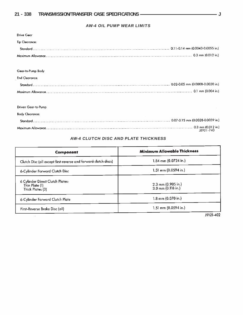
AW-4 OIL PUMP WEAR LIMITS
AW-4 CLUTCH DISC AND PLATE THICKNESS
21 - 338 TRANSMISSION/TRANSFER CASE SPECIFICATIONS J

AW-4 BUSHING AND PISTON CLEARANCE
J TRANSMISSION/TRANSFER CASE SPECIFICATIONS 21 - 339

AW-4 RETAINER AND PISTON SPECIFICATIONS
21 - 340 TRANSMISSION/TRANSFER CASE SPECIFICATIONS J

AW-4 VALVE BODY CHECK BALL DIMENSIONS
AW-4 CLUTCH AND BRAKE PACK REQUIREMENTS
J TRANSMISSION/TRANSFER CASE SPECIFICATIONS 21 - 341

AW-4 ACCUMULATOR COMPONENTIDENTIFICATION
21 - 342 TRANSMISSION/TRANSFER CASE SPECIFICATIONS J

AW-4 VALVE AND SPRING IDENTIFICATION
J TRANSMISSION/TRANSFER CASE SPECIFICATIONS 21 - 343

AW-4 TORQUE SPECIFICATIONS
NP231/NP242 TORQUE SPECIFICATIONS
21 - 344 TRANSMISSION/TRANSFER CASE SPECIFICATIONS J