Jeep Cherokee XJ 1995-1999 Front Suspension
50
FRONT SUSPENSION AND AXLE CONTENTS page page AXLE NOISE/VIBRATION DIAGNOSIS ........ 18 AXLE SPECIFICATIONS ................... 49 FRONT WHEEL ALIGNMENT ................ 5 GENERAL INFORMATION .................. 1 MODEL 30 AXLE AND TUBE AXLE (2WD) .... 22 TORQUE SPECIFICATIONS ................ 49 XJ FRONT SUSPENSION .................. 11 YJ FRONT SUSPENSION .................. 15 GENERAL INFORMATION FRONT SUSPENSION XJ VEHICLES The XJ front suspension is a link/coil design. This suspension is use on Left Hand Drive (LHD) and Right Hand Drive (RHD) vehicles. It is comprised of (Fig. 1); • Drive axle (4WD), tube axle (2WD) • Track bar • Stabilizer bar • Upper and lower suspension arms • Coil springs • Dual-action shock absorbers • Jounce bumpers The link/coil suspension allows each wheel to adapt to different road surfaces without greatly affecting Fig. 1 XJ Front Suspension (LHD) J FRONT SUSPENSION AND AXLE 2-1
-
Upload
shane-sullivan -
Category
Documents
-
view
509 -
download
2
Transcript of Jeep Cherokee XJ 1995-1999 Front Suspension

FRONT SUSPENSION AND AXLE
CONTENTS
page page
AXLE NOISE/VIBRATION DIAGNOSIS . . . . . . . . 18AXLE SPECIFICATIONS . . . . . . . . . . . . . . . . . . . 49FRONT WHEEL ALIGNMENT . . . . . . . . . . . . . . . . 5GENERAL INFORMATION . . . . . . . . . . . . . . . . . . 1
MODEL 30 AXLE AND TUBE AXLE (2WD) . . . . 22TORQUE SPECIFICATIONS . . . . . . . . . . . . . . . . 49XJ FRONT SUSPENSION . . . . . . . . . . . . . . . . . . 11YJ FRONT SUSPENSION . . . . . . . . . . . . . . . . . . 15
GENERAL INFORMATION
FRONT SUSPENSION
XJ VEHICLESThe XJ front suspension is a link/coil design. This
suspension is use on Left Hand Drive (LHD) andRight Hand Drive (RHD) vehicles. It is comprised of(Fig. 1);• Drive axle (4WD), tube axle (2WD)
• Track bar• Stabilizer bar• Upper and lower suspension arms• Coil springs• Dual-action shock absorbers• Jounce bumpers
The link/coil suspension allows each wheel to adaptto different road surfaces without greatly affecting
Fig. 1 XJ Front Suspension (LHD)
J FRONT SUSPENSION AND AXLE 2 - 1
the opposite wheel. Wheels are attached to a hub/bearings which bolts to the knuckles. The hub/bear-ing is not serviceable and is replaced as a unit.Steering knuckles pivot on replaceable ball studs at-tached to the axle tube yokes.
The upper and lower suspension arms are differentlengths, with bushings at both ends. They bolt theaxle assembly to the body. The lower arms usesshims at the body mount to allow for adjustment ofcaster and drive shaft pinion angle. The suspensionarm travel is limited through the use of jouncebumpers in compression and shocks absorbers in re-bound.
Suspension components which use rubber bushingsshould be tightened at vehicle ride height. This willprevent premature failure of the bushing and main-tain ride comfort. Bushings must never be lubricated.
The coil springs control ride quality and maintainproper ride height. The coil springs mount up in thefender shield which is part of the unitized bodybracket. A rubber isolator is located between the topof the spring and the frame. The bottom of the springseats on a axle pad and is retained with a clip.
The shock absorbers dampen jounce and rebound ofthe vehicle over various road conditions. The top ofthe shock absorbers are bolted to the body. The bot-tom of the shocks are bolted to the axle springbracket.
The stabilizer bar is used to minimize vehicle bodyroll during turns. The spring steel bar helps to con-trol the vehicle body in relationship to the suspen-sion. The bar extends across the front underside ofthe chassis and connects to the body rails. Links areconnected from the bar to the axle brackets. Stabi-lizer bar mounts are isolated by rubber bushings.
The track bar is used to minimize front axle side-to-side movement. The bar is attached to a frame railbracket with a ball stud and isolated with a bushingat the axle bracket.
TUBE AXLE (2WD VEHICLES)The front axle used on two-wheel drive vehicles is
a one-piece, tubular axle (Fig. 2). The tubular axlemounts in the same bracketry as the four-wheeldrive axle.
The steering knuckles and hub bearing assembliesare the same as used on the Model 30 drive axle.
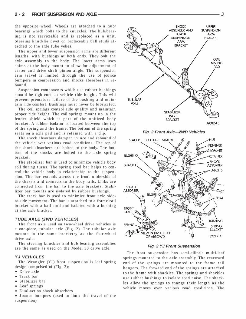
YJ VEHICLESThe Wrangler (YJ) front suspension is leaf spring
design comprised of (Fig. 3);• Drive axle• Track bar• Stabilizer bar• Leaf springs• Dual-action shock absorbers• Jounce bumpers (used to limit the travel of thesuspension)
The front suspension has semi-elliptic multi-leafsprings mounted to the axle assembly. The rearwardend of the springs are mounted to the frame railhangers. The forward end of the springs are attachedto the frame with shackles. The springs and shacklesuse rubber bushings to isolate road noise. The shack-les allow the springs to change their length as thevehicle moves over various road conditions. The
Fig. 2 Front Axle—2WD Vehicles
Fig. 3 YJ Front Suspension
2 - 2 FRONT SUSPENSION AND AXLE J
spring and axle travel (jounce or rebound) is limitedthrough use of rubber bumpers mounted on theframe.
Suspension components which use rubber bushingsshould be tightened at vehicle ride height. This willprevent premature failure of the bushing and main-tain ride comfort. The bushings should never be lu-bricated.
The shocks absorbers dampen jounce and reboundof the vehicle over various road conditions. The top ofthe shock absorbers bolt to the frame. The bottom ofthe shocks bolt to the axle brackets.
The stabilizer bar is used to minimize vehicle frontsway during turns. The spring steel bar helps controlvehicle body in relationship to the suspension move-ment. The bar extends across the front underside ofthe chassis and connects to the frame rails. Linksconnect the bar to the axle brackets. Stabilizer barmounts are isolated by rubber bushings.
The track bar is used to minimize front axle side-to-side movement. The track bar is attached to aframe rail bracket and axle bracket. The bar usesbushings at both ends.
FRONT DRIVE AXLEIt is not necessary to remove the complete axle
from the vehicle for routine differential service. If thedifferential housing or axle shaft tubes are damaged,the complete axle assembly can be removed and ser-viced.
For complete drive axle assembly removal and in-stallation refer to Drive Axle Assembly Replacementin this Group.
The removable cover provides for servicing withoutremoving axle from vehicle.
The integral type housing, hypoid gear design hasthe centerline of the pinion set above the centerlineof the ring gear.
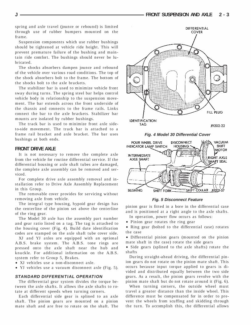
The Model 30 axle has the assembly part numberand gear ratio listed on a tag. The tag is attached tothe housing cover (Fig. 4). Build date identificationcodes are stamped on the axle shaft tube cover side.
XJ and YJ axles are equipped with an optionalA.B.S. brake system. The A.B.S. tone rings arepressed onto the axle shaft near the hub andknuckle. For additional information on the A.B.S.system refer to Group 5, Brakes.• XJ vehicles use a non-disconnect axle.• YJ vehicles use a vacuum disconnect axle (Fig. 5).
STANDARD DIFFERENTIAL OPERATIONThe differential gear system divides the torque be-
tween the axle shafts. It allows the axle shafts to ro-tate at different speeds when turning corners.
Each differential side gear is splined to an axleshaft. The pinion gears are mounted on a pinionmate shaft and are free to rotate on the shaft. The
pinion gear is fitted in a bore in the differential caseand is positioned at a right angle to the axle shafts.
In operation, power flow occurs as follows:• Pinion gear rotates the ring gear• Ring gear (bolted to the differential case) rotatesthe case• Differential pinion gears (mounted on the pinionmate shaft in the case) rotate the side gears• Side gears (splined to the axle shafts) rotate theshafts
During straight-ahead driving, the differential pin-ion gears do not rotate on the pinion mate shaft. Thisoccurs because input torque applied to gears is di-vided and distributed equally between the two sidegears. As a result, the pinion gears revolve with thepinion mate shaft but do not rotate around it (Fig. 6).
When turning corners, the outside wheel musttravel a greater distance than the inside wheel. Thisdifference must be compensated for in order to pre-vent the wheels from scuffing and skidding throughthe turn. To accomplish this, the differential allows
Fig. 4 Model 30 Differential Cover
Fig. 5 Disconnect Feature
J FRONT SUSPENSION AND AXLE 2 - 3
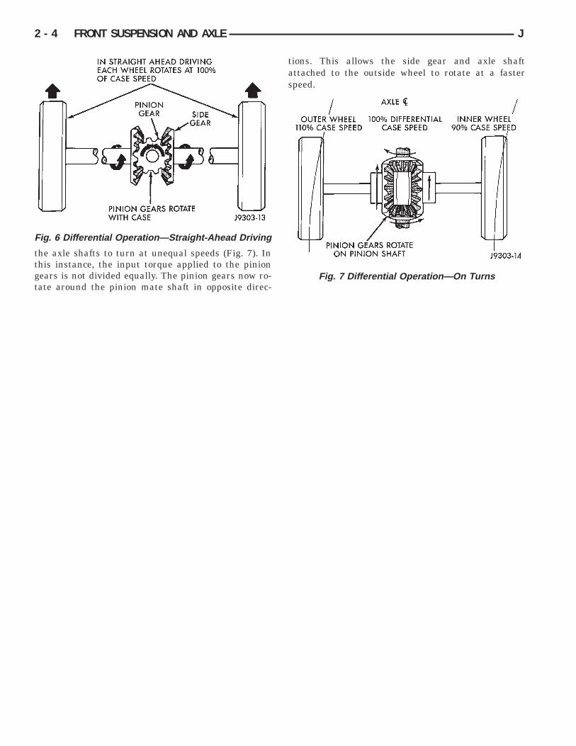
the axle shafts to turn at unequal speeds (Fig. 7). Inthis instance, the input torque applied to the piniongears is not divided equally. The pinion gears now ro-tate around the pinion mate shaft in opposite direc-
tions. This allows the side gear and axle shaftattached to the outside wheel to rotate at a fasterspeed.
Fig. 6 Differential Operation—Straight-Ahead Driving
Fig. 7 Differential Operation—On Turns
2 - 4 FRONT SUSPENSION AND AXLE J
FRONT WHEEL ALIGNMENT
INDEX
page page
Alignment Measurements and Adjustments . . . . . . . 8General Information . . . . . . . . . . . . . . . . . . . . . . . . 5
Pre-Alignment Inspection . . . . . . . . . . . . . . . . . . . . 6
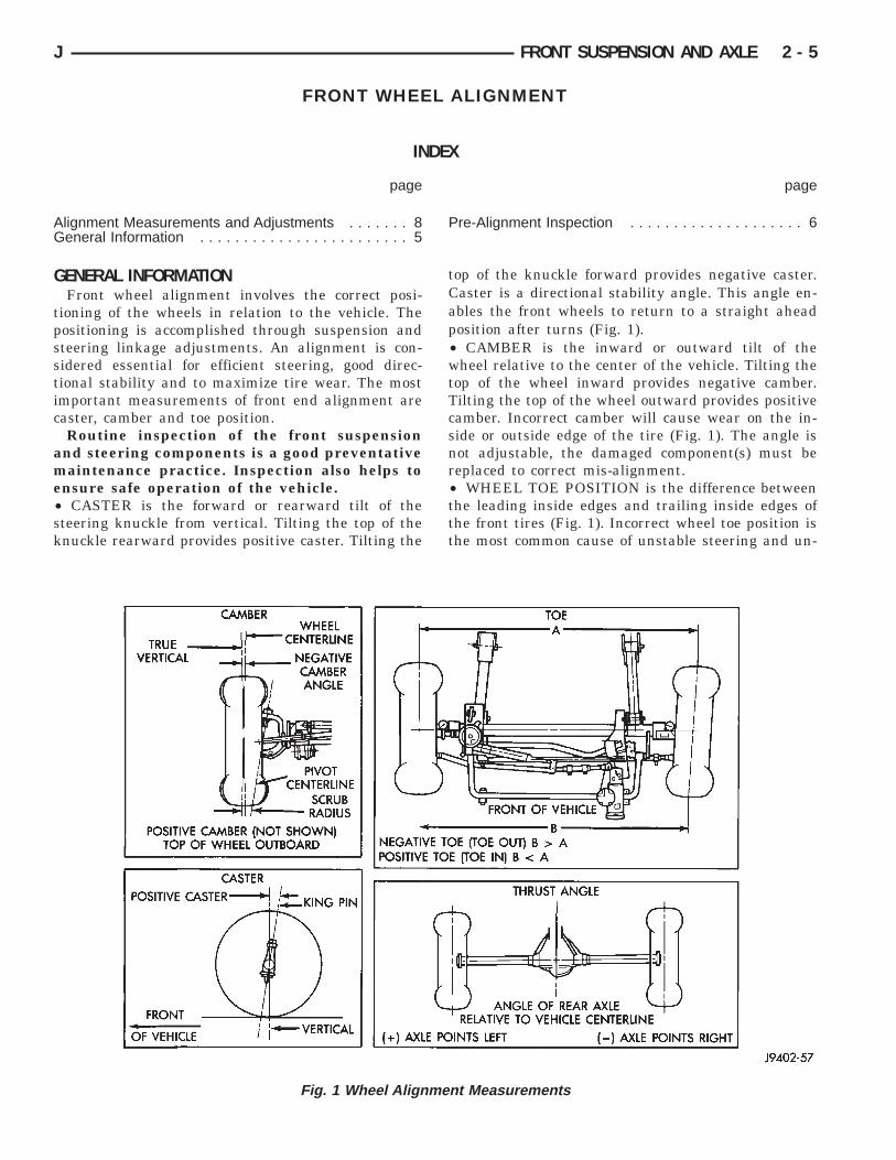
GENERAL INFORMATIONFront wheel alignment involves the correct posi-
tioning of the wheels in relation to the vehicle. Thepositioning is accomplished through suspension andsteering linkage adjustments. An alignment is con-sidered essential for efficient steering, good direc-tional stability and to maximize tire wear. The mostimportant measurements of front end alignment arecaster, camber and toe position.
Routine inspection of the front suspensionand steering components is a good preventativemaintenance practice. Inspection also helps toensure safe operation of the vehicle.• CASTER is the forward or rearward tilt of thesteering knuckle from vertical. Tilting the top of theknuckle rearward provides positive caster. Tilting the
top of the knuckle forward provides negative caster.Caster is a directional stability angle. This angle en-ables the front wheels to return to a straight aheadposition after turns (Fig. 1).• CAMBER is the inward or outward tilt of thewheel relative to the center of the vehicle. Tilting thetop of the wheel inward provides negative camber.Tilting the top of the wheel outward provides positivecamber. Incorrect camber will cause wear on the in-side or outside edge of the tire (Fig. 1). The angle isnot adjustable, the damaged component(s) must bereplaced to correct mis-alignment.• WHEEL TOE POSITION is the difference betweenthe leading inside edges and trailing inside edges ofthe front tires (Fig. 1). Incorrect wheel toe position isthe most common cause of unstable steering and un-
Fig. 1 Wheel Alignment Measurements
J FRONT SUSPENSION AND AXLE 2 - 5

even tire wear. The wheel toe position is the finalfront wheel alignment adjustment.• STEERING AXIS INCLINATION ANGLE is mea-sured in degrees and is the angle that the steeringknuckles are tilted (Fig. 1). The inclination angle hasa fixed relationship with the camber angle. It will notchange except when a spindle or ball stud is dam-aged or bent. The angle is not adjustable, the dam-aged component(s) must be replaced to correct mis-alignment.
WARNING: DO NOT ATTEMPT TO MODIFY ANYSUSPENSION OR STEERING COMPONENT BYHEATING AND BENDING.
PRE-ALIGNMENT INSPECTIONBefore starting a front wheel alignment, the follow-
ing inspection and necessary corrections must becompleted.
(1) Tires with the same recommended air pressure,size, and thread wear. Refer to Group 22, Tires AndWheels for diagnosis information.
(2) Front wheel bearings for wear and looseness.(3) Ball studs, steering linkage pivot points and
steering gear for looseness, roughness, binding orwear. Refer to Group 19, Steering for additional in-formation.
(4) Front wheels for excessive radial or lateralrunout and unbalance. Refer to Group 22, Tires AndWheels for diagnosis information.
(5) Suspension components for wear. Check compo-nents for correct torque. Refer to Groups 2 and 3,Suspension and Axle for additional information.
2 - 6 FRONT SUSPENSION AND AXLE J

SUSPENSION AND STEERING SYSTEM DIAGNOSIS
J FRONT SUSPENSION AND AXLE 2 - 7

ALIGNMENT MEASUREMENTS AND ADJUSTMENTSBefore each alignment reading, the vehicle should
be jounced (rear first, then front). Grasp eachbumper at the center and jounce the vehicle up anddown several times. Always release the bumper inthe down position. Set the front end alignment tospecifications with the vehicle at its NOR-MALLY RIDE HEIGHT.
CAMBERThe wheel camber angle is preset. This angle is not
adjustable and cannot be altered.
CASTERBefore checking the caster of the front axle for cor-
rect angle, be sure the axle is not bent or twisted.Road test the vehicle, make left and right turns. If
the steering wheel returns to the center position un-assisted, the caster angle is correct. If steering wheel
does not return toward the center position unas-sisted, an incorrect caster angle is probable.
Caster can be adjusted by installing the appropri-ate size shims (Fig. 2, 3). Changing caster anglewill also change the front propeller shaft angle.The propeller shaft angle has priority overcaster. Refer to Group 16, Propeller Shafts foradditional information.
TOE POSITION—XJ VEHICLESThe wheel toe position adjustment should be the fi-
nal adjustment.(1) Start the engine if equipped with power steer-
ing. Turn wheels both ways before straightening the
Fig. 2 Adjustment—YJ Vehicles
Fig. 3 Adjustment—XJ Vehicles
Fig. 4 Steering Linkage—XJ (LHD)
2 - 8 FRONT SUSPENSION AND AXLE J

wheels. Secure the steering wheel with the frontwheels in the straight-ahead position. Turn off theengine.
(2) Loosen the adjustment sleeve clamp bolts (Fig.4, 5).
(3) Adjust the right wheel toe position with thedrag link. Turn the sleeve until the right wheel is atspecifications. Position the clamp bolts as shown (Fig.6) and tighten to 49 Nzm (36 ft. lbs.) torque. Makesure the toe setting does not change duringclamp tightening.
(4) Adjust the left wheel toe position with the tierod. Turn the sleeve until the left wheel is at specifi-cations. Position the clamp bolts as shown (Fig. 6)and tighten to 27 Nzm (20 ft. lbs.) torque. Make surethe toe setting does not change during clamptightening.
(5) Verify the right toe setting.
Fig. 5 Steering Linkage—XJ (RHD)
Fig. 6 Drag Link and Tie Rod Clamp Location (LHD)
J FRONT SUSPENSION AND AXLE 2 - 9
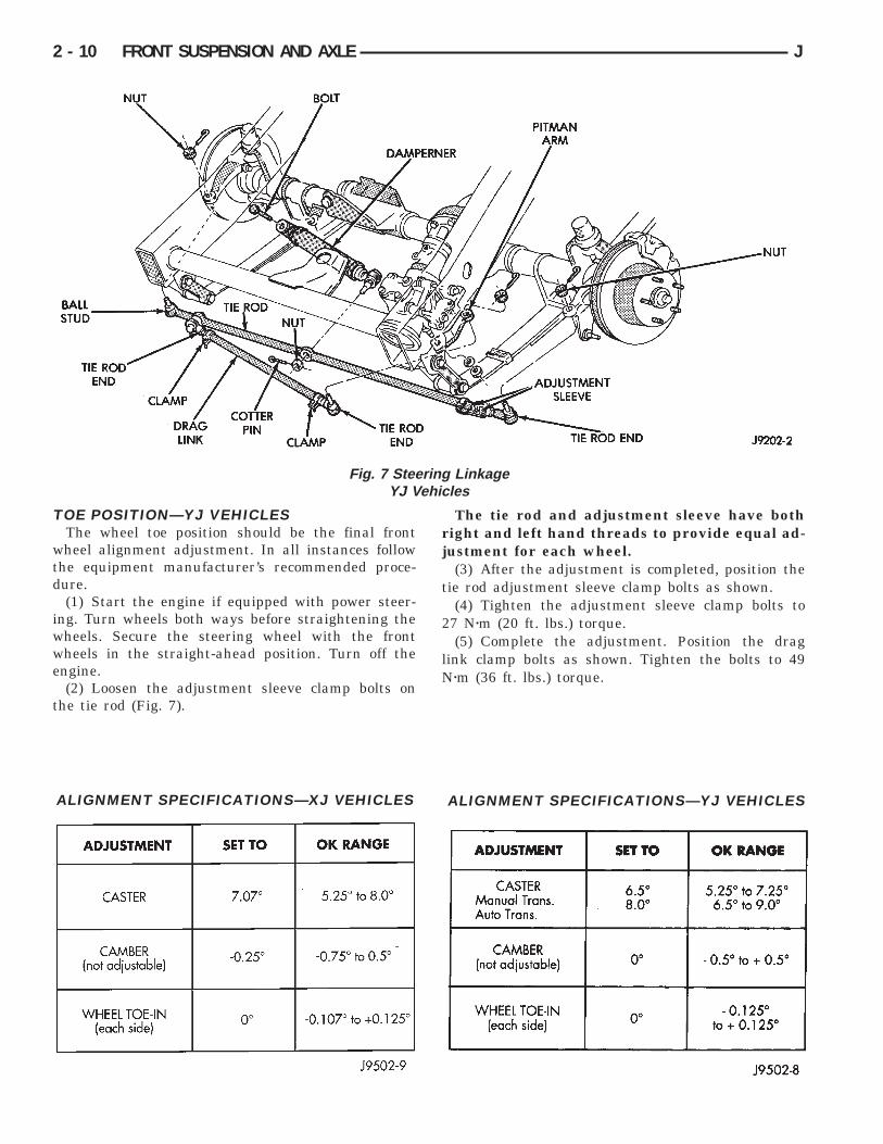
TOE POSITION—YJ VEHICLESThe wheel toe position should be the final front
wheel alignment adjustment. In all instances followthe equipment manufacturer’s recommended proce-dure.
(1) Start the engine if equipped with power steer-ing. Turn wheels both ways before straightening thewheels. Secure the steering wheel with the frontwheels in the straight-ahead position. Turn off theengine.
(2) Loosen the adjustment sleeve clamp bolts onthe tie rod (Fig. 7).
The tie rod and adjustment sleeve have bothright and left hand threads to provide equal ad-justment for each wheel.
(3) After the adjustment is completed, position thetie rod adjustment sleeve clamp bolts as shown.
(4) Tighten the adjustment sleeve clamp bolts to27 Nzm (20 ft. lbs.) torque.
(5) Complete the adjustment. Position the draglink clamp bolts as shown. Tighten the bolts to 49Nzm (36 ft. lbs.) torque.
Fig. 7 Steering LinkageYJ Vehicles
ALIGNMENT SPECIFICATIONS—XJ VEHICLES ALIGNMENT SPECIFICATIONS—YJ VEHICLES
2 - 10 FRONT SUSPENSION AND AXLE J

XJ FRONT SUSPENSION
INDEX
page page
Axle Bushing Replacement . . . . . . . . . . . . . . . . . . 12Coil Spring . . . . . . . . . . . . . . . . . . . . . . . . . . . . . . 14Lower Suspension Arm . . . . . . . . . . . . . . . . . . . . . 13Service Information . . . . . . . . . . . . . . . . . . . . . . . . 11Shock Absorber . . . . . . . . . . . . . . . . . . . . . . . . . . 13
Spring and Shock Diagnosis . . . . . . . . . . . . . . . . . 13Stabilizer Bar . . . . . . . . . . . . . . . . . . . . . . . . . . . . 11Track Bar . . . . . . . . . . . . . . . . . . . . . . . . . . . . . . . 11Upper Suspension Arm . . . . . . . . . . . . . . . . . . . . . 12
SERVICE INFORMATIONPeriodic lubrication of the steering system and sus-
pension components is required. Refer to Group 0,Lubrication And Maintenance for the service inter-val.
CAUTION: Suspension components with rubberbushings should be tightened with the vehicle atnormal height. It is important to have the springssupporting the weight of the vehicle when the fas-teners are torqued. If springs are not at their normalride position, vehicle ride comfort could be affectedand premature bushing wear may occur. Rubberbushings must never be lubricated.
TRACK BAR
REMOVAL(1) Raise and support the vehicle.(2) Remove the cotter pin and nut from the ball
stud end at the frame rail bracket (Fig. 1).A puller tool may be necessary to separate the
ball stud from the frame rail bracket.(3) Remove the bolt and flag nut from the axle
shaft tube bracket (Fig. 1). Remove the track bar.
INSTALLATION(1) Install the track bar at axle tube bracket.
Loosely install the retaining bolt and flag nut (Fig.1).
(2) It may be necessary to pry the axle assemblyover to install the track bar at the frame rail. Installtrack bar at the frame rail bracket. Install the re-taining nut on the stud (Fig. 1).
(3) Remove the supports and lower the vehicle.(4) Tighten the retaining bolt at the axle shaft
tube bracket to 100 Nzm (74 ft. lbs.) torque.(5) Tighten the ball stud nut to 81 Nzm (60 ft. lbs.)
torque. Install a new cotter pin.
STABILIZER BAR
REMOVAL(1) Raise and support the vehicle.(2) Disconnect the stabilizer bar links from the
axle brackets (Fig. 2).(3) Disconnect the stabilizer bar from the links.(4) Disconnect the stabilizer bar clamps from the
frame rails. Remove the stabilizer bar.
INSTALLATION(1) Inspect stabilizer bar bushings ( Fig. 2). Re-
place bushings if cracked, cut, distorted, or worn.(2) Position the stabilizer bar on the frame rail and
install the bushings and clamps. Ensure the bar iscentered with equal spacing on both sides. Tightenthe bolts to 75 Nzm (40 ft. lbs.).
(3) Install the links and grommets onto the stabi-lizer bar and axle brackets (Fig. 2). Tighten the nutat the connecting links at the axle bracket to 95 Nzm(70 ft. lbs.) torque.
Fig. 1 Track Bar (LHD)
J FRONT SUSPENSION AND AXLE 2 - 11

(3) Tighten the stabilizer bar to connecting linknut to 36 Nzm (27 ft. lbs.) torque.
(4) Remove the supports and lower the vehicle.
UPPER SUSPENSION ARM
REMOVAL(1) Raise and support the vehicle.(2) Remove the upper suspension arm nut and bolt
at the axle bracket (Fig. 3).(3) Remove the nut and bolt (Fig. 3) at the frame
rail and remove the upper suspension arm.
INSTALLATION(1) Position the upper suspension arm at the axle
and frame rail (Fig. 3).(2) Install the bolts and finger tighten the nuts
(Fig. 3).(3) Remove the supports and lower the vehicle.(4) Tighten the nut at the axle to 75 Nzm (55 ft.
lbs.) torque.Tighten the nut at the frame bracket to 90 Nzm (66
ft. lbs.) torque.
AXLE BUSHING REPLACEMENT(1) Remove the upper suspension arm from axle.
Refer to Upper Suspension Arm Removal in thisGroup.
(2) Insert Spacer 7932-3 (J-35581-3) around thebushing in the axle bracket ears (Fig. 4).
(3) Assemble and install Bushing Removal/In-staller (Fig. 4).
(4) Remove the bushing by tightening the hex-headon Long Nut.
For two-wheel drive axles and right side onModel 30 axle, do not remove Spacer 7932-3 (J-35581-3) at this time.
(5) Position the new bushing on Installer.(6) Install the bushing by tightening the hex-head
on Long Nut (Fig. 5). Remove Spacer 7932-3 (J-35581-3).
(7) Install the upper suspension arm to axle. Referto Upper Suspension Arm Installation in this Group.
Fig. 2 Stabilizer Bar Fig. 3 Upper and Lower Suspension Arms
Fig. 4 Axle Bracket Bushing Removal
2 - 12 FRONT SUSPENSION AND AXLE J
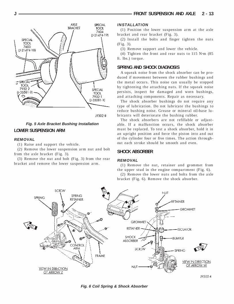
LOWER SUSPENSION ARM
REMOVAL(1) Raise and support the vehicle.(2) Remove the lower suspension arm nut and bolt
from the axle bracket (Fig. 3).(3) Remove the nut and bolt (Fig. 3) from the rear
bracket and remove the lower suspension arm.
INSTALLATION(1) Position the lower suspension arm at the axle
bracket and rear bracket (Fig. 3).(2) Install the bolts and finger tighten the nuts
(Fig. 3).(3) Remove support and lower the vehicle.(4) Tighten the front and rear nuts to 115 Nzm (85
ft. lbs.) torque.
SPRING AND SHOCK DIAGNOSISA squeak noise from the shock absorber can be pro-
duced if movement between the rubber bushings andthe metal occurs. This noise can usually be stoppedby tightening the attaching nuts. If the squeak noisepersists, inspect for damaged and worn bushings,and attaching components. Repair as necessary.
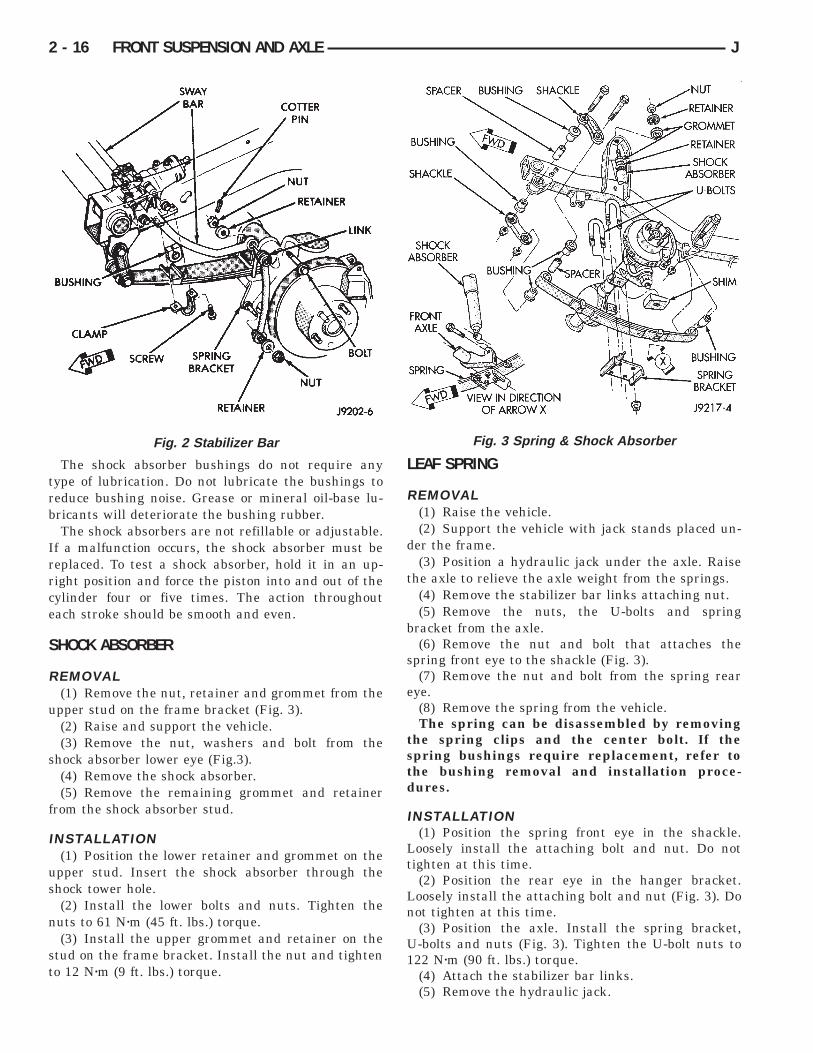
The shock absorber bushings do not require anytype of lubrication. Do not lubricate the bushings toreduce bushing noise. Grease or mineral oil-base lu-bricants will deteriorate the bushing rubber.
The shock absorbers are not refillable or adjust-able. If a malfunction occurs, the shock absorbermust be replaced. To test a shock absorber, hold it inan upright position and force the piston into and outof the cylinder four or five times. The action through-out each stroke should be smooth and even.
SHOCK ABSORBER
REMOVAL(1) Remove the nut, retainer and grommet from
the upper stud in the engine compartment (Fig. 6).(2) Remove the lower nuts and bolts from the axle
bracket (Fig. 6). Remove the shock absorber.
Fig. 6 Coil Spring & Shock Absorber
Fig. 5 Axle Bracket Bushing Installation
J FRONT SUSPENSION AND AXLE 2 - 13
INSTALLATION(1) Position the lower retainer and grommet on the
upper stud. Insert the shock absorber through theshock tower hole.
(2) Install the lower bolts and nuts. Tighten nutsto 23 Nzm (17 ft. lbs.) torque.
(3) Install the upper grommet and retainer on thestud in the engine compartment. Install the nut andtighten to 10 Nzm (8 ft. lbs.) torque.
COIL SPRING
REMOVAL(1) Raise and support the vehicle. Position a hy-
draulic jack under the axle to support it.(2) Remove the wheel if necessary.(3) Mark and disconnect the front propeller shaft
from the axle.(4) Disconnect the lower suspension arms from the
axle (Fig. 6).(5) Disconnect the stabilizer bar link and shock ab-
sorber from the axle.(6) Disconnect the track bar from the frame rail
bracket.
(7) Disconnect the drag link from the pitman arm.(8) Lower the axle until the spring is free from the
upper mount. Remove the coil spring clip (Fig. 6) andremove the spring.
(9) Pull jounce bumper out of mount.
INSTALLATION(1) Install jounce bumper into mount.(2) Position the coil spring on the axle pad. Install
the spring clip and bolt (Fig. 6). Tighten bolt to 21Nzm (16 ft. lbs.) torque.
(3) Raise the axle into position until the springseats in the upper mount.
(4) Connect the stabilizer bar links and shock ab-sorbers to the axle bracket. Connect the track bar tothe frame rail bracket.
(5) Install the lower suspension arms to the axle.DO NOT TIGHTEN AT THIS TIME.
(6) Install the front propeller shaft to the axle.(7) Remove the supports and lower the vehicle.(8) Tighten lower suspension arms nuts to 115 Nzm
(85 ft. lbs.) torque.
2 - 14 FRONT SUSPENSION AND AXLE J

YJ FRONT SUSPENSION
INDEX
page page
Leaf Spring . . . . . . . . . . . . . . . . . . . . . . . . . . . . . . 16Leaf Spring Eye Bushing Replacement . . . . . . . . . 17Service Information . . . . . . . . . . . . . . . . . . . . . . . . 15Shock Absorber . . . . . . . . . . . . . . . . . . . . . . . . . . 16
Spring and Shock Diagnosis . . . . . . . . . . . . . . . . . 15Stabilizer Bar . . . . . . . . . . . . . . . . . . . . . . . . . . . . 15Track Bar . . . . . . . . . . . . . . . . . . . . . . . . . . . . . . . 15
SERVICE INFORMATIONPeriodic lubrication of the steering system and sus-
pension components is required. Refer to Group 0,Lubrication And Maintenance for the service inter-val.
CAUTION: Suspension components with rubberbushings should be tightened with the vehicle atnormal height. It is important to have the springssupporting the weight of the vehicle when the fas-teners are torqued. If springs are not at their normalride position, vehicle ride comfort could be affectedand premature bushing wear may occur. Rubberbushings must never be lubricated.
TRACK BAR
REMOVAL(1) Raise and support the vehicle.(2) Remove the retaining nuts and bolts (Fig. 1)
from the axle bracket and frame bracket. Removetrack bar.
INSTALLATION(1) Position track bar at axle shaft tube bracket.
Loosely install the retaining bolt and nut (Fig. 1).(2) Loosely install the retaining bolt and nut at the
frame bracket.(3) Remove support and lower vehicle.(4) Tighten the retaining nut at the axle shaft tube
bracket to 100 Nzm (74 ft. lbs.) torque.(5) Tighten the retaining nut at the frame bracket
to 142 Nzm (105 ft. lbs.) torque.
STABILIZER BAR
REMOVAL(1) Raise and support the vehicle.(2) Remove the retaining nut from the connecting
link bolt (Fig. 2).(3) Remove the retaining clamps from frame rails(4) Remove the stabilizer bar.
INSTALLATION(1) Inspect the stabilizer bar bushings (Fig. 2). Re-
place the bushings if cracked, cut, distorted, or worn.
(2) Position the stabilizer bar on the frame. Installthe retaining brackets and fasteners. Tighten bolts to41 Nzm (30 ft. lbs.) torque.
(3) Install the link upper bolts and nuts. Tightenthe nuts to 61 Nzm (45 ft. lbs.) torque.
(4) Tighten the link spring bracket nuts to 61 Nzm(45 ft. lbs.) torque.
(5) Lower the vehicle.
SPRING AND SHOCK DIAGNOSISA squeak noise from the shock absorber or springs
can be produced if movement between the rubberbushings and the metal occurs. This noise can usu-ally be stopped by tightening the attaching nuts. Ifthe squeak noise persists, inspect for damaged andworn bushings, and attaching components. Repair asnecessary if any of these conditions exist.
Fig. 1 Track Bar
J FRONT SUSPENSION AND AXLE 2 - 15
The shock absorber bushings do not require anytype of lubrication. Do not lubricate the bushings toreduce bushing noise. Grease or mineral oil-base lu-bricants will deteriorate the bushing rubber.
The shock absorbers are not refillable or adjustable.If a malfunction occurs, the shock absorber must bereplaced. To test a shock absorber, hold it in an up-right position and force the piston into and out of thecylinder four or five times. The action throughouteach stroke should be smooth and even.
SHOCK ABSORBER
REMOVAL(1) Remove the nut, retainer and grommet from the
upper stud on the frame bracket (Fig. 3).(2) Raise and support the vehicle.(3) Remove the nut, washers and bolt from the
shock absorber lower eye (Fig.3).(4) Remove the shock absorber.(5) Remove the remaining grommet and retainer
from the shock absorber stud.
INSTALLATION(1) Position the lower retainer and grommet on the
upper stud. Insert the shock absorber through theshock tower hole.
(2) Install the lower bolts and nuts. Tighten thenuts to 61 Nzm (45 ft. lbs.) torque.
(3) Install the upper grommet and retainer on thestud on the frame bracket. Install the nut and tightento 12 Nzm (9 ft. lbs.) torque.
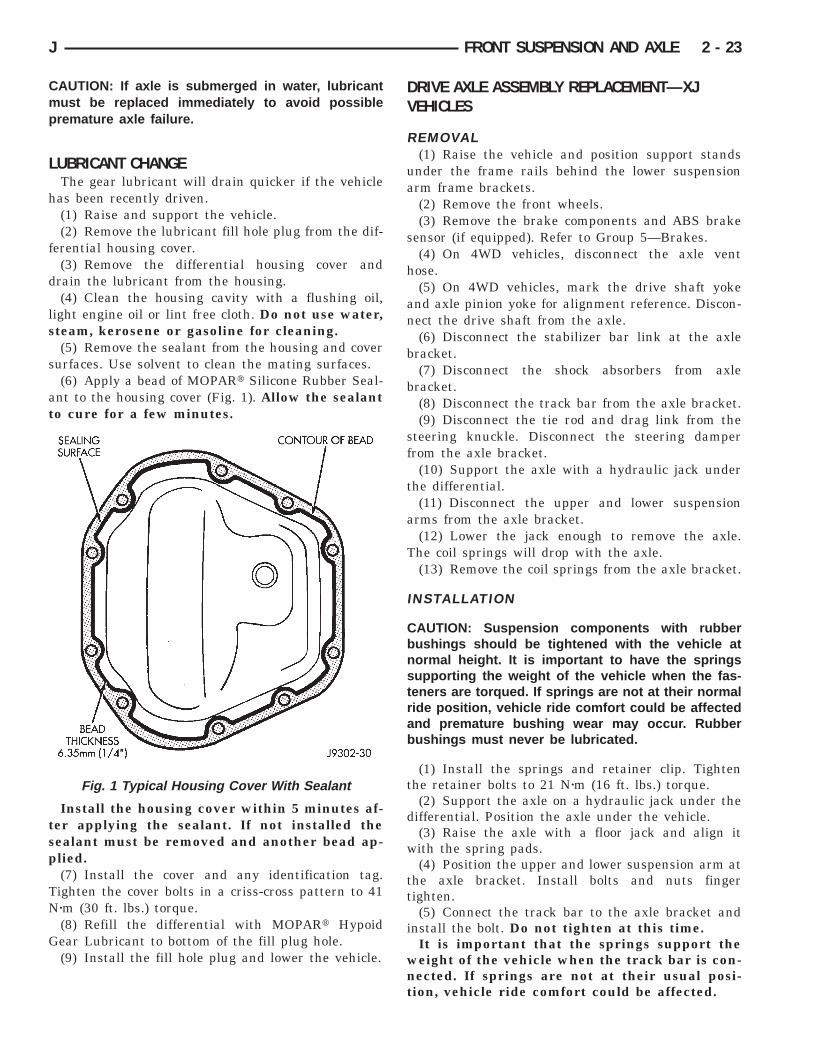
LEAF SPRING
REMOVAL(1) Raise the vehicle.(2) Support the vehicle with jack stands placed un-
der the frame.(3) Position a hydraulic jack under the axle. Raise
the axle to relieve the axle weight from the springs.(4) Remove the stabilizer bar links attaching nut.(5) Remove the nuts, the U-bolts and spring
bracket from the axle.(6) Remove the nut and bolt that attaches the
spring front eye to the shackle (Fig. 3).(7) Remove the nut and bolt from the spring rear
eye.(8) Remove the spring from the vehicle.The spring can be disassembled by removing
the spring clips and the center bolt. If thespring bushings require replacement, refer tothe bushing removal and installation proce-dures.
INSTALLATION(1) Position the spring front eye in the shackle.
Loosely install the attaching bolt and nut. Do nottighten at this time.
(2) Position the rear eye in the hanger bracket.Loosely install the attaching bolt and nut (Fig. 3). Donot tighten at this time.
(3) Position the axle. Install the spring bracket,U-bolts and nuts (Fig. 3). Tighten the U-bolt nuts to122 Nzm (90 ft. lbs.) torque.
(4) Attach the stabilizer bar links.(5) Remove the hydraulic jack.
Fig. 2 Stabilizer Bar Fig. 3 Spring & Shock Absorber
2 - 16 FRONT SUSPENSION AND AXLE J

(6) Remove the support stands and lower the vehi-cle.
(7) Tighten the front shackle plate nut (Fig. 3) to135 Nzm (100 ft. lbs.) torque.
(8) Tighten the rear eye bracket nut to 142 Nzm(105 ft. lbs.) torque.
LEAF SPRING EYE BUSHING REPLACEMENT(1) Assemble tools shown (Fig. 4). Tighten the nut
located at the socket wrench end of the threaded roduntil the bushing is forced out.
(2) Assemble and align the bushing installationtools.
(3) Align the bushing with the spring eye andtighten the nut located at the socket wrench end ofthe threaded rod. Tighten until the bushing is forcedinto the spring eye.
The bushing must be centered in the springeye. The ends of the bushing must be flush orslightly recessed within the end surfaces of thespring eye.
Fig. 4 Spring Eye Bushing Removal
J FRONT SUSPENSION AND AXLE 2 - 17

AXLE NOISE/VIBRATION DIAGNOSIS
INDEX
page page
Driveline Snap . . . . . . . . . . . . . . . . . . . . . . . . . . . 19Gear and Bearing Noise . . . . . . . . . . . . . . . . . . . . 18General Information . . . . . . . . . . . . . . . . . . . . . . . 18
Low Speed Knock . . . . . . . . . . . . . . . . . . . . . . . . . 19Vibration . . . . . . . . . . . . . . . . . . . . . . . . . . . . . . . . 19
GENERAL INFORMATIONAxle bearing problem conditions are usually caused
by:• Insufficient or incorrect lubricant• Foreign matter/water contamination• Incorrect bearing preload torque adjustment• Incorrect backlash (to tight)
When serviced, the bearings must be cleaned thor-oughly. They should be dried with lint-free shop tow-els. Never dry bearings with compressed air.This will overheat them and brinell the bearingsurfaces. This will result in noisy operation af-ter repair.
Axle gear problem conditions are usually the resultof:• Insufficient lubrication• Incorrect or contaminated lubricant• Overloading (excessive engine torque) or exceedingvehicle weight capacity• Incorrect clearance or backlash adjustment
Insufficient lubrication is usually the result of ahousing cover leak. It can also be from worn axleshaft or pinion gear seals. Check for cracks or porousareas in the housing or tubes.
Using the wrong lubricant will cause overheatingand gear failure. Gear tooth cracking and bearingspalling are indicators of this.
Axle component breakage is most often the resultof:• Severe overloading• Insufficient lubricant• Incorrect lubricant• Improperly tightened components
Overloading occurs when towing heavier than rec-ommended loads. Component breakage can occurwhen the wheels are spun excessively. Incorrect lu-bricant quantity contributes to breakage. Loose dif-ferential components can also cause breakage.
Incorrect bearing preload or gear backlash will notresult in component breakage. Mis-adjustment willproduce enough noise to cause service repair before afailure occurs. If a mis-adjustment condition is notcorrected, component failure can result.
Excessive bearing preload may not be noisy. Thiscondition will cause high temperature which can re-sult in bearing failure.
GEAR AND BEARING NOISE
GEAR NOISEAxle gear noise can be caused by insufficient lubri-
cant. Incorrect backlash, tooth contact, or worn/dam-aged gears can cause noise.
Gear noise usually happens at a specific speedrange. The range is 30 to 40 mph, or above 50 mph.The noise can also occur during a specific type ofdriving condition. These conditions are acceleration,deceleration, coast, or constant load.
When road testing, accelerate the vehicle to thespeed range where the noise is the greatest. Shiftout-of-gear and coast through the peak-noise range.If the noise stops or changes greatly, check for insuf-ficient lubricant. Incorrect ring gear backlash, orgear damage can cause noise changes.
Differential side and pinion gears can be checkedby turning the vehicle. They usually do not causenoise in straight-ahead driving. These gears areloaded during vehicle turns. If noise does occur dur-ing vehicle turns, the side or pinion gears could beworn or damaged. A worn pinion gear mate shaft canalso cause a snapping or a knocking noise.
BEARING NOISEThe axle shaft, differential and pinion gear bear-
ings can all produce noise when worn or damaged.Bearing noise can be either a whining, or a growlingsound.
Pinion gear bearings have a constant-pitch noise.This noise changes only with vehicle speed. Pinionbearing noise will be higher because it rotates at afaster rate. Drive the vehicle and load the differen-tial. If bearing noise occurs the pinion rear bearing isthe source of the noise. If the bearing noise is heardduring a coast, front bearing is the source.
Worn, damaged differential bearings usually pro-duce a low pitch noise. Differential bearing noise issimilar to pinion bearing. The pitch of differentialbearing noise is also constant and varies only withvehicle speed.
2 - 18 FRONT SUSPENSION AND AXLE J

Axle shaft bearings produce noise and vibrationwhen worn or damaged. The noise generally changeswhen the bearings are loaded. Road test the vehicle.Turn the vehicle sharply to the left and to the right.This will load the bearings and change the noiselevel. Where axle bearing damage is slight, the noiseis usually not noticeable at speeds above 30 mph.
LOW SPEED KNOCKLow speed knock is generally caused by a worn U-
joint or by worn side-gear thrust washers. A wornpinion gear shaft bore will also cause low speedknock.
VIBRATIONVibration at the rear of the vehicle is usually
caused by a:• Damaged drive shaft• Missing drive shaft balance weight• Worn, out-of-balance wheels• Loose wheel lug nuts• Worn U-joint• Loose spring U-bolts• Loose/broken springs• Damaged axle shaft bearings• Loose pinion gear nut• Excessive pinion yoke run out
• Bent axle shaftCheck for loose or damaged front-end components
or engine/transmission mounts. These componentscan contribute to what appears to be a rear-end vi-bration. Do not overlook engine accessories, bracketsand drive belts.
All driveline components should be examined be-fore starting any repair.
Refer to Group 22—Tires And Wheels for addi-tional information involving vibration diagnosis.
DRIVELINE SNAPA snap or clunk noise when the vehicle is shifted
into gear (or the clutch engaged), can be caused by:• High engine idle speed• Loose engine/transmission/transfer case mounts• Worn U-joints• Loose spring mounts• Loose pinion gear nut and yoke• Excessive ring gear backlash• Excessive differential side gear-to-case clearance
The source of a snap or a clunk noise can be deter-mined with the assistance of a helper. Raise the ve-hicle on a hoist with the wheels free to rotate.Instruct the helper to shift the transmission intogear. Listen for the noise, a mechanics stethoscope ishelpful in isolating the source of a noise.
J FRONT SUSPENSION AND AXLE 2 - 19

SERVICE DIAGNOSIS
2 - 20 FRONT SUSPENSION AND AXLE J

SERVICE DIAGNOSIS (CONT’D)
J FRONT SUSPENSION AND AXLE 2 - 21

MODEL 30 AXLE AND TUBE AXLE (2WD)
INDEX
page page
Axle Bushing Replacement . . . . . . . . . . . . . . . . . . 34Axle Shaft—Cardan U-Joint . . . . . . . . . . . . . . . . . . 26Backlash and Contact Pattern Analysis . . . . . . . . . 45Cleaning/Inspection . . . . . . . . . . . . . . . . . . . . . . . . 37Differential and Pinion Measurement . . . . . . . . . . . 40Differential Assembly . . . . . . . . . . . . . . . . . . . . . . . 38Differential Disassembly . . . . . . . . . . . . . . . . . . . . 35Differential Installation . . . . . . . . . . . . . . . . . . . . . . 44Differential Removal . . . . . . . . . . . . . . . . . . . . . . . 34Differential Shim Pack Measurement and
Adjustment . . . . . . . . . . . . . . . . . . . . . . . . . . . . 43Drive Axle Assembly Replacement—XJ Vehicles . . 23Drive Axle Assembly Replacement—YJ Vehicles . . 24
Final Assembly . . . . . . . . . . . . . . . . . . . . . . . . . . . 46Hub Bearing and Axle Shaft . . . . . . . . . . . . . . . . . 25Information . . . . . . . . . . . . . . . . . . . . . . . . . . . . . . 22Inner Axle Shaft Oil Seal Replacement . . . . . . . . . 35Lubricant Change . . . . . . . . . . . . . . . . . . . . . . . . . 23Lubricant Specifications . . . . . . . . . . . . . . . . . . . . . 22Pinion Gear Assembly/Installation . . . . . . . . . . . . . 42Pinion Gear Depth Information . . . . . . . . . . . . . . . 39Pinion Removal/Disassembly . . . . . . . . . . . . . . . . . 36Pinion Seal Replacement . . . . . . . . . . . . . . . . . . . 25Steering Knuckle and Ball Studs . . . . . . . . . . . . . . 32Vacuum Disconnect Axle—YJ Vehicles . . . . . . . . . 27
INFORMATIONThe Model 30 front axles consists of a cast iron dif-
ferential housing with axle shaft tubes extendingfrom either side. The tubes are pressed into the dif-ferential housing and welded.
The integral type housing, hypoid gear design hasthe centerline of the pinion set above the centerlineof the ring gear.
The axle has a fitting for a vent hose used to re-lieve internal pressure caused by lubricant vaporiza-tion and internal expansion.
The axles are equipped with semi-floating axleshafts, meaning that loads are supported by the hubbearings. The axle shafts are retained by nuts at thehub bearings. The hub bearings are bolted to thesteering knuckle at the outboard end of the axle tubeyoke. The hub bearings are serviced as an assembly.
The axles are equipped with ABS brake sensors.The sensors are attached to the knuckle assembliesand tone rings are pressed on the axle shaft. Usecare when removing axle shafts as NOT to dam-age the tone wheel or the sensor.
The stamped steel cover provides a means for in-spection and servicing the differential.
The Model 30 axle has the assembly part numberand gear ratio listed on a tag. The tag is attached tothe housing cover. Build date identification codes arestamped on the axle shaft tube cover side.
The differential case is a one-piece design. The dif-ferential pinion mate shaft is retained with a rollpin. Differential bearing preload and ring gear back-lash is adjusted by the use of shims (select thick-ness). The shims are located between the differentialbearing cones and case. Pinion bearing preload is setand maintained by the use of collapsible spacer.
COMMAND-TRAC—YJ VEHICLESThe Command-Trac system is a vacuum disconnect
axle. The system has a two-piece axle shaft coupledtogether by a shift collar. For two-wheel drive opera-tion, the vacuum motor and shift fork disengages theaxle shaft splines. For four-wheel drive operation, thevacuum motor and shift fork engages the axlesplines.
SELEC-TRAC—XJ VEHICLESThe Selec-Trac system is a non-disconnect axle.
Shifting from two-wheel to four-wheel drive is doneat the transfer case.
For XJ vehicles equipped with Selec-Trac andABS brake system, refer to Group 5—Brakes for ad-ditional service information.
LUBRICANT SPECIFICATIONSMulti-purpose, hypoid gear lubricant should be
used for Model 30 axles. The lubricant should haveMIL-L-2105C and API GL 5 quality specifications.MOPARt Hypoid Gear Lubricant conforms to both ofthese specifications.• The factory fill for the Model 30 axle is SAE Ther-mally Stable 80W-90 gear lubricant. Do not useheavier weight lubricant, this will cause axleengagement difficulties.• The factory installed lubricant quantity for theNON-DISCONNECT TYPE AXLE is 1.48 L (3.13pts.).• The factory installed lubricant quantity for theVACUUM-DISCONNECT TYPE AXLE is 1.65 L (3.76pts.).
Refer to Group 0, Lubrication and Maintenance foradditional information regarding temperature range,viscosity and fluid level.
2 - 22 FRONT SUSPENSION AND AXLE J
CAUTION: If axle is submerged in water, lubricantmust be replaced immediately to avoid possiblepremature axle failure.
LUBRICANT CHANGEThe gear lubricant will drain quicker if the vehicle
has been recently driven.(1) Raise and support the vehicle.(2) Remove the lubricant fill hole plug from the dif-
ferential housing cover.(3) Remove the differential housing cover and
drain the lubricant from the housing.(4) Clean the housing cavity with a flushing oil,
light engine oil or lint free cloth. Do not use water,steam, kerosene or gasoline for cleaning.
(5) Remove the sealant from the housing and coversurfaces. Use solvent to clean the mating surfaces.
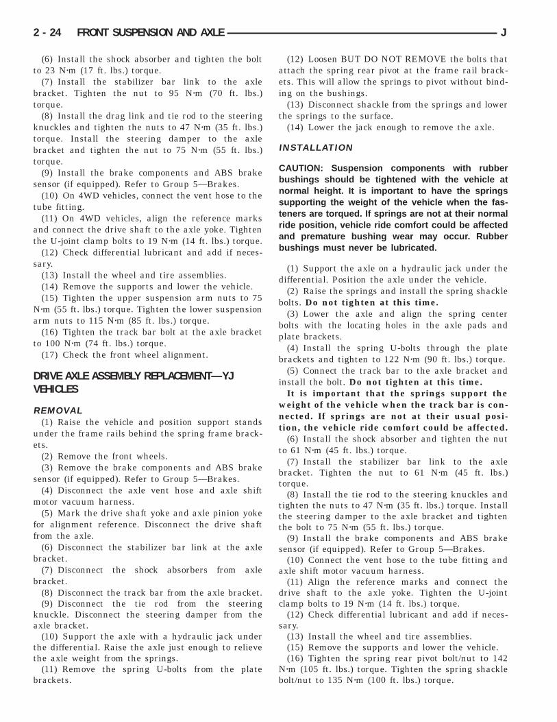
(6) Apply a bead of MOPARt Silicone Rubber Seal-ant to the housing cover (Fig. 1). Allow the sealantto cure for a few minutes.
Install the housing cover within 5 minutes af-ter applying the sealant. If not installed thesealant must be removed and another bead ap-plied.
(7) Install the cover and any identification tag.Tighten the cover bolts in a criss-cross pattern to 41Nzm (30 ft. lbs.) torque.
(8) Refill the differential with MOPARt HypoidGear Lubricant to bottom of the fill plug hole.
(9) Install the fill hole plug and lower the vehicle.
DRIVE AXLE ASSEMBLY REPLACEMENT—XJVEHICLES
REMOVAL(1) Raise the vehicle and position support stands
under the frame rails behind the lower suspensionarm frame brackets.
(2) Remove the front wheels.(3) Remove the brake components and ABS brake
sensor (if equipped). Refer to Group 5—Brakes.(4) On 4WD vehicles, disconnect the axle vent
hose.(5) On 4WD vehicles, mark the drive shaft yoke
and axle pinion yoke for alignment reference. Discon-nect the drive shaft from the axle.
(6) Disconnect the stabilizer bar link at the axlebracket.
(7) Disconnect the shock absorbers from axlebracket.
(8) Disconnect the track bar from the axle bracket.(9) Disconnect the tie rod and drag link from the
steering knuckle. Disconnect the steering damperfrom the axle bracket.
(10) Support the axle with a hydraulic jack underthe differential.
(11) Disconnect the upper and lower suspensionarms from the axle bracket.
(12) Lower the jack enough to remove the axle.The coil springs will drop with the axle.
(13) Remove the coil springs from the axle bracket.
INSTALLATION
CAUTION: Suspension components with rubberbushings should be tightened with the vehicle atnormal height. It is important to have the springssupporting the weight of the vehicle when the fas-teners are torqued. If springs are not at their normalride position, vehicle ride comfort could be affectedand premature bushing wear may occur. Rubberbushings must never be lubricated.
(1) Install the springs and retainer clip. Tightenthe retainer bolts to 21 Nzm (16 ft. lbs.) torque.
(2) Support the axle on a hydraulic jack under thedifferential. Position the axle under the vehicle.
(3) Raise the axle with a floor jack and align itwith the spring pads.
(4) Position the upper and lower suspension arm atthe axle bracket. Install bolts and nuts fingertighten.
(5) Connect the track bar to the axle bracket andinstall the bolt. Do not tighten at this time.
It is important that the springs support theweight of the vehicle when the track bar is con-nected. If springs are not at their usual posi-tion, vehicle ride comfort could be affected.
Fig. 1 Typical Housing Cover With Sealant
J FRONT SUSPENSION AND AXLE 2 - 23
(6) Install the shock absorber and tighten the boltto 23 Nzm (17 ft. lbs.) torque.
(7) Install the stabilizer bar link to the axlebracket. Tighten the nut to 95 Nzm (70 ft. lbs.)torque.
(8) Install the drag link and tie rod to the steeringknuckles and tighten the nuts to 47 Nzm (35 ft. lbs.)torque. Install the steering damper to the axlebracket and tighten the nut to 75 Nzm (55 ft. lbs.)torque.
(9) Install the brake components and ABS brakesensor (if equipped). Refer to Group 5—Brakes.
(10) On 4WD vehicles, connect the vent hose to thetube fitting.
(11) On 4WD vehicles, align the reference marksand connect the drive shaft to the axle yoke. Tightenthe U-joint clamp bolts to 19 Nzm (14 ft. lbs.) torque.
(12) Check differential lubricant and add if neces-sary.
(13) Install the wheel and tire assemblies.(14) Remove the supports and lower the vehicle.(15) Tighten the upper suspension arm nuts to 75
Nzm (55 ft. lbs.) torque. Tighten the lower suspensionarm nuts to 115 Nzm (85 ft. lbs.) torque.
(16) Tighten the track bar bolt at the axle bracketto 100 Nzm (74 ft. lbs.) torque.
(17) Check the front wheel alignment.
DRIVE AXLE ASSEMBLY REPLACEMENT—YJVEHICLES
REMOVAL(1) Raise the vehicle and position support stands
under the frame rails behind the spring frame brack-ets.
(2) Remove the front wheels.(3) Remove the brake components and ABS brake
sensor (if equipped). Refer to Group 5—Brakes.(4) Disconnect the axle vent hose and axle shift
motor vacuum harness.(5) Mark the drive shaft yoke and axle pinion yoke
for alignment reference. Disconnect the drive shaftfrom the axle.
(6) Disconnect the stabilizer bar link at the axlebracket.
(7) Disconnect the shock absorbers from axlebracket.
(8) Disconnect the track bar from the axle bracket.(9) Disconnect the tie rod from the steering
knuckle. Disconnect the steering damper from theaxle bracket.
(10) Support the axle with a hydraulic jack underthe differential. Raise the axle just enough to relievethe axle weight from the springs.
(11) Remove the spring U-bolts from the platebrackets.
(12) Loosen BUT DO NOT REMOVE the bolts thatattach the spring rear pivot at the frame rail brack-ets. This will allow the springs to pivot without bind-ing on the bushings.
(13) Disconnect shackle from the springs and lowerthe springs to the surface.
(14) Lower the jack enough to remove the axle.
INSTALLATION
CAUTION: Suspension components with rubberbushings should be tightened with the vehicle atnormal height. It is important to have the springssupporting the weight of the vehicle when the fas-teners are torqued. If springs are not at their normalride position, vehicle ride comfort could be affectedand premature bushing wear may occur. Rubberbushings must never be lubricated.
(1) Support the axle on a hydraulic jack under thedifferential. Position the axle under the vehicle.
(2) Raise the springs and install the spring shacklebolts. Do not tighten at this time.
(3) Lower the axle and align the spring centerbolts with the locating holes in the axle pads andplate brackets.
(4) Install the spring U-bolts through the platebrackets and tighten to 122 Nzm (90 ft. lbs.) torque.
(5) Connect the track bar to the axle bracket andinstall the bolt. Do not tighten at this time.
It is important that the springs support theweight of the vehicle when the track bar is con-nected. If springs are not at their usual posi-tion, the vehicle ride comfort could be affected.
(6) Install the shock absorber and tighten the nutto 61 Nzm (45 ft. lbs.) torque.
(7) Install the stabilizer bar link to the axlebracket. Tighten the nut to 61 Nzm (45 ft. lbs.)torque.
(8) Install the tie rod to the steering knuckles andtighten the nuts to 47 Nzm (35 ft. lbs.) torque. Installthe steering damper to the axle bracket and tightenthe bolt to 75 Nzm (55 ft. lbs.) torque.
(9) Install the brake components and ABS brakesensor (if equipped). Refer to Group 5—Brakes.
(10) Connect the vent hose to the tube fitting andaxle shift motor vacuum harness.
(11) Align the reference marks and connect thedrive shaft to the axle yoke. Tighten the U-jointclamp bolts to 19 Nzm (14 ft. lbs.) torque.
(12) Check differential lubricant and add if neces-sary.
(13) Install the wheel and tire assemblies.(15) Remove the supports and lower the vehicle.(16) Tighten the spring rear pivot bolt/nut to 142
Nzm (105 ft. lbs.) torque. Tighten the spring shacklebolt/nut to 135 Nzm (100 ft. lbs.) torque.
2 - 24 FRONT SUSPENSION AND AXLE J

(17) Tighten the track bar nut at the axle bracketto 100 Nzm (74 ft. lbs.) torque.
(18) Check the front wheel alignment.
PINION SEAL REPLACEMENT
REMOVAL(1) Raise and support the vehicle.(2) Remove wheel and tire assemblies.(3) Mark the propeller shaft yoke and pinion yoke
for installation alignment reference.(4) Remove the propeller shaft from the yoke.(5) Remove the pinion yoke nut and washer. Use
Remover C-452 and Wrench C-3281 to remove thepinion yoke (Fig. 2).
(6) Mark the positions of the yoke and pinion gearfor installation alignment reference.
(7) Use Remover 7794A and slide hammer to re-move the pinion gear seal (Fig. 3).
INSTALLATION(1) Apply a light coating of gear lubricant on the
lip of pinion seal. Install seal with Installer D-163and Handle C-4171 (Fig. 4).
(2) Align the reference marks and install yoke onthe pinion gear with Installer W-162-D.
(3) Install a new pinion nut on pinion shaft. Tightenthe nut to 217-352 Nzm (160-260 ft. lbs.) (Fig. 5).
(4) Align the installation reference marks and at-tach the propeller shaft to the yoke.
(5) Add API grade GL 5 hypoid gear lubricant tothe differential housing, if necessary.
(6) Install wheel and tire assemblies.(7) Remove support and lower the vehicle.
HUB BEARING AND AXLE SHAFT
REMOVAL(1) Raise and support the vehicle.(2) Remove the wheel and tire assembly.(3) Remove the brake components from the axle,
refer to Group 5, Brakes.(4) Remove the cotter pin, nut retainer and axle
hub nut (Fig. 6).(5) Remove the hub to knuckle bolts (Fig. 6). Remove
the hub from the steering knuckle and axle shaft.(6) Remove the disc brake rotor shield from the
bearing carrier (Fig. 6).(7) On disconnect axles, remove vacuum shift mo-
tor housing. Refer to Vacuum Disconnect Axle in thissection.
(8) Remove the axle shaft from the housing. Avoiddamaging the axle shaft oil seals in the differen-tial.
Fig. 2 Pinion Yoke Removal
Fig. 3 Seal Removal
Fig. 4 Pinion Seal Installation
J FRONT SUSPENSION AND AXLE 2 - 25

INSTALLATION(1) Thoroughly clean the axle shaft (Fig. 6) and ap-
ply a thin film of Mopar Wheel Bearing Grease to theshaft splines, seal contact surface, hub bore.
(2) Install the axle shaft into the housing and dif-ferential side gears. Avoid damaging the axle shaftoil seals in the differential.
(3) Install the hub bearing and brake dust shieldto the knuckle.
(4) Install the hub to knuckle bolts and tighten to102 Nzm (75 ft. lbs.) torque.
(5) Install the hub washer and nut. Tighten thehub nut to 237 Nzm (175 ft. lbs.) torque. Install thenut retainer and a new cotter pin (Fig. 6).
(6) Install the brake components, refer to Group 5,Brakes.
(7) Install the wheel and tire assembly.(8) Remove support and lower the vehicle.
AXLE SHAFT—CARDAN U-JOINT
DISASSEMBLYSingle cardan U-joints are not serviceable. If defec-
tive, they must be replaced as a unit. If the bearings,seals, spider or bearing caps are damaged or worn,replace the complete U-joint.
CAUTION: Clamp only the forged portion of theyoke in the vise. Also, to avoid distorting the yoke,do not over tighten the vise jaws.
(1) Remove the bearing cap retaining snap rings(Fig. 7).
It can be helpful to saturate the bearing capswith penetrating oil prior to removal.
(2) Locate a socket that is larger in diameter thanthe bearing cap. Place the socket (receiver) againstthe yoke and around the perimeter of the bearing capto be removed. Locate a socket that is smaller in di-ameter than the bearing cap. Place the socket (driv-er) against the opposite bearing cap. Position theyoke with the sockets in a vise (Fig. 8).
(3) Compress the vise jaws to force the bearing capinto the larger socket (receiver).
(4) Release the vise jaws. Remove the sockets andbearing cap that was partially forced out of the yoke.
(5) Repeat the above procedure for the remainingbearing cap.
Fig. 6 Hub, Knuckle and Axle Shaft
Fig. 7 Axle Shaft Outer U-Joint
2 - 26 FRONT SUSPENSION AND AXLE J
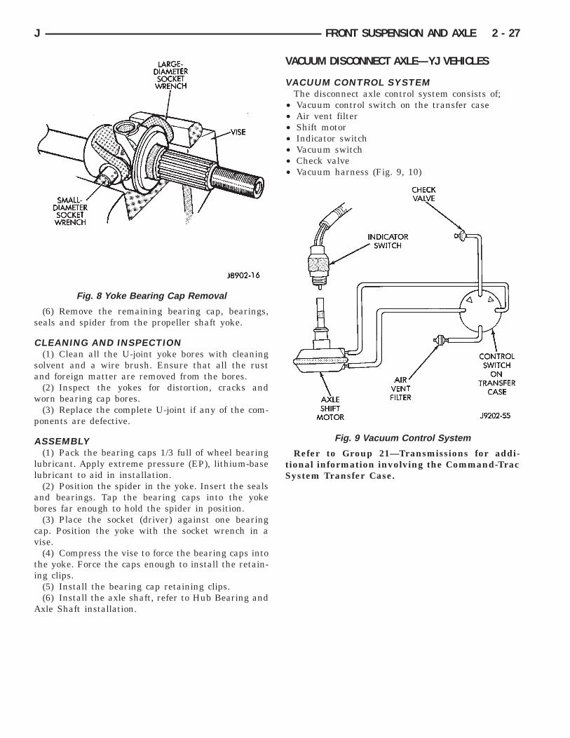
(6) Remove the remaining bearing cap, bearings,seals and spider from the propeller shaft yoke.
CLEANING AND INSPECTION(1) Clean all the U-joint yoke bores with cleaning
solvent and a wire brush. Ensure that all the rustand foreign matter are removed from the bores.
(2) Inspect the yokes for distortion, cracks andworn bearing cap bores.
(3) Replace the complete U-joint if any of the com-ponents are defective.
ASSEMBLY(1) Pack the bearing caps 1/3 full of wheel bearing
lubricant. Apply extreme pressure (EP), lithium-baselubricant to aid in installation.
(2) Position the spider in the yoke. Insert the sealsand bearings. Tap the bearing caps into the yokebores far enough to hold the spider in position.
(3) Place the socket (driver) against one bearingcap. Position the yoke with the socket wrench in avise.
(4) Compress the vise to force the bearing caps intothe yoke. Force the caps enough to install the retain-ing clips.
(5) Install the bearing cap retaining clips.(6) Install the axle shaft, refer to Hub Bearing and
Axle Shaft installation.
VACUUM DISCONNECT AXLE—YJ VEHICLES
VACUUM CONTROL SYSTEMThe disconnect axle control system consists of;
• Vacuum control switch on the transfer case• Air vent filter• Shift motor• Indicator switch• Vacuum switch• Check valve• Vacuum harness (Fig. 9, 10)
Refer to Group 21—Transmissions for addi-tional information involving the Command-TracSystem Transfer Case.
Fig. 8 Yoke Bearing Cap Removal
Fig. 9 Vacuum Control System
J FRONT SUSPENSION AND AXLE 2 - 27

Fig. 10 Vacuum Hose Routing
2 - 28 FRONT SUSPENSION AND AXLE J

DISCONNECT AXLE/SHIFT MOTOR DIAGNOSIS
J FRONT SUSPENSION AND AXLE 2 - 29

DISCONNECT AXLE/SHIFT MOTOR DIAGNOSIS (CONT’D)
2 - 30 FRONT SUSPENSION AND AXLE J

SHIFT MOTOR—REMOVAL/DISASSEMBLY(1) Disconnect the vacuum and wiring connector
from the shift housing.(2) Remove indicator switch.(3) Remove the shift motor housing cover, gasket
and shield from the housing (Fig. 11).
(4) Remove the E-clips from the shift motor hous-ing and shaft. Remove shift motor and shift fork fromthe housing (Fig. 12).
(5) Remove the O-ring seal from the shift motorshaft.
(6) Clean and inspect all components. If any com-ponent is excessively worn or damaged, it should bereplaced.
ASSEMBLY/INSTALLATION(1) Install a new O-ring seal on the shift motor
shaft.(2) Insert the shift motor shaft through the hole in
the housing and shift fork. The shift fork offsetshould be toward the differential.
(3) Install the E-clips on the shift motor shaft andhousing.
(4) Install the shift motor housing gasket andcover. Ensure the shift fork is correctly guidedinto the shift collar groove.
(5) Install the shift motor housing shield and at-taching bolts. Tighten the bolts to 11 Nzm (101 in.lbs.) torque.
(6) Add 148 ml (5 ounces) of API grade GL 5 hy-poid gear lubricant to the shift motor housing. Addlubricant through indicator switch mounting hole.
(7) Install indicator switch, electrical connectorand vacuum harness.
INTERMEDIATE AXLE SHAFT—REMOVAL/DISASSEMBLY
Service to the Disconnect axle seals and bearing re-quire the use of Tool Set 6288 (J34659) and Seal In-staller 6228.
(1) Remove the vacuum motor housing. Refer toShift Motor Removal in this section.
(3) Remove the outer axle shaft. Refer to HubBearing and Axle Shaft in this section.
(4) Remove shift collar and intermediate axleshaft.
(5) Remove the inner axle shaft seal from the shiftmotor housing (Fig. 13).
(6) Remove the intermediate axle shaft bearing(Fig. 14).
ASSEMBLY/INSTALLATION(1) Position the bearing on installation tool. Seat
the bearing in the housing bore (Fig. 15).(2) Clean the inside perimeter of the axle shaft
tube with fine crocus cloth.(3) Apply a light film of oil to the inside lip of the
new axle shaft seal.(4) Install the inner axle seal (Fig. 16, 17).The axle shaft seal primary installation tool
6228-1 will only force the seal partially into the
Fig. 11 Shift Motor Housing and Shift Collar
Fig. 12 Vacuum Shift Motor Components Fig. 13 Axle Shaft Inner Seal Removal
J FRONT SUSPENSION AND AXLE 2 - 31
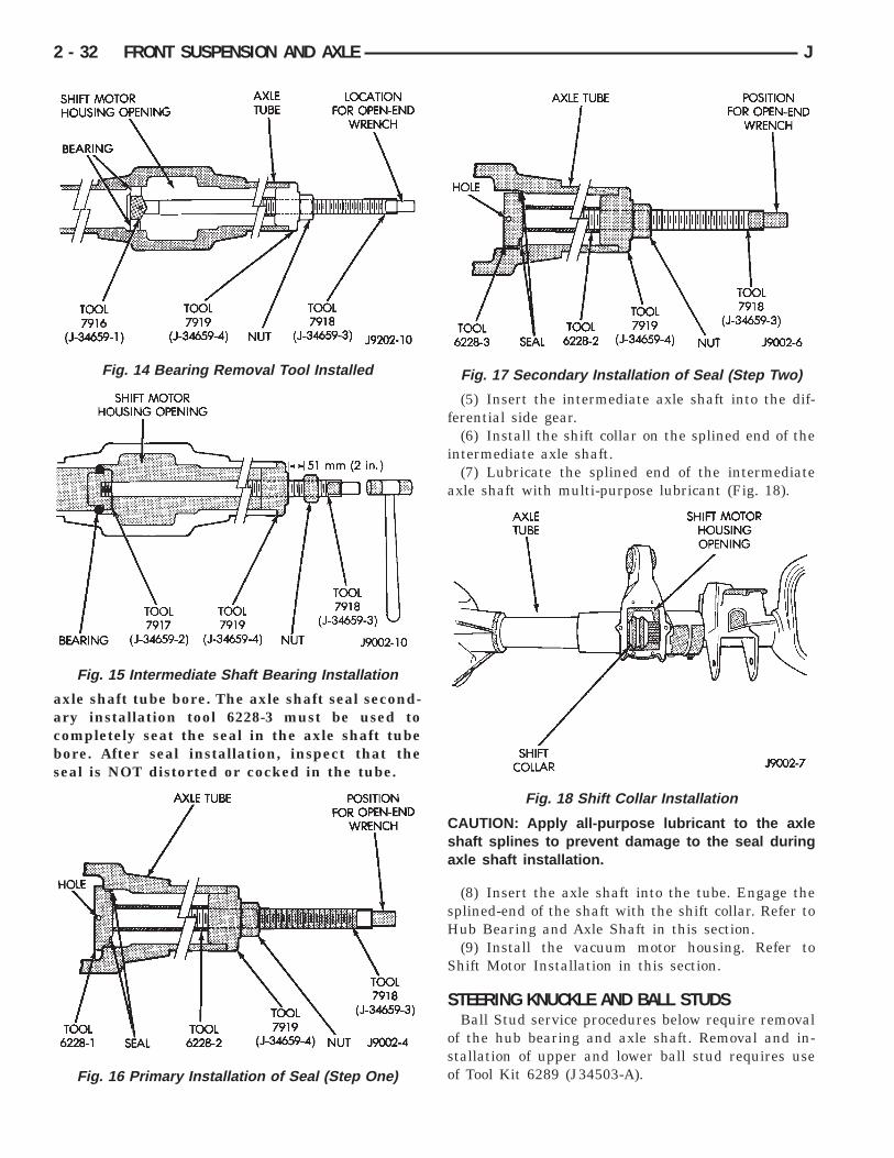
axle shaft tube bore. The axle shaft seal second-ary installation tool 6228-3 must be used tocompletely seat the seal in the axle shaft tubebore. After seal installation, inspect that theseal is NOT distorted or cocked in the tube.
(5) Insert the intermediate axle shaft into the dif-ferential side gear.
(6) Install the shift collar on the splined end of theintermediate axle shaft.
(7) Lubricate the splined end of the intermediateaxle shaft with multi-purpose lubricant (Fig. 18).
CAUTION: Apply all-purpose lubricant to the axleshaft splines to prevent damage to the seal duringaxle shaft installation.
(8) Insert the axle shaft into the tube. Engage thesplined-end of the shaft with the shift collar. Refer toHub Bearing and Axle Shaft in this section.
(9) Install the vacuum motor housing. Refer toShift Motor Installation in this section.
STEERING KNUCKLE AND BALL STUDSBall Stud service procedures below require removal
of the hub bearing and axle shaft. Removal and in-stallation of upper and lower ball stud requires useof Tool Kit 6289 (J34503-A).
Fig. 14 Bearing Removal Tool Installed
Fig. 15 Intermediate Shaft Bearing Installation
Fig. 16 Primary Installation of Seal (Step One)
Fig. 17 Secondary Installation of Seal (Step Two)
Fig. 18 Shift Collar Installation
2 - 32 FRONT SUSPENSION AND AXLE J

The lower ball stud has two different designs. Forthis reason installer 6752 will also be needed. Checkinstallers for proper fit.
KNUCKLE REMOVAL(1) Remove hub bearing and axle shaft refer to the
Removal procedure.(2) Disconnect the tie-rod or drag link end from the
steering knuckle arm. Remove the ABS sensor wireand bracket from knuckle.
(3) Remove the cotter pins from the upper andlower ball studs. Remove the upper and lower ballstud nuts.
(4) Strike the steering knuckle with a brass ham-mer to loosen. Remove knuckle from axle tube yokes(Fig. 19).
UPPER BALL STUD REPLACEMENT(1) Position tools as shown to remove and install
ball stud (Fig. 20).
LOWER BALL STUD REPLACEMENT(1) Position tools as shown to remove and install
ball stud (Fig.21). Because there are two different de-signs for the lower ball studs try both installers forproper fit.
KNUCKLE INSTALLATION(1) Position the steering knuckle on the ball studs.
(2) Install and tighten the bottom retaining nut to109 Nzm (80 ft. lbs.) torque. Install new cotter pin.
(3) Install and tighten the top retaining nut to 101Nzm (75 ft. lbs.) torque. Install new cotter pin.
Fig. 19 Steering Knuckle Removal/Installation
Fig. 20 Upper Ball Stud Remove/Install
J FRONT SUSPENSION AND AXLE 2 - 33

(4) Install the Hub Bearing and Axle Shaft accord-ing to the installation procedure.
(5) Reconnect the tie-rod or drag link end onto thesteering knuckle arm. Install the ABS sensor wireand bracket to the knuckle, refer to Group 5 Brakes.
AXLE BUSHING REPLACEMENTRefer to Axle Bushing Replacement in the Front
Suspension section.
DIFFERENTIAL REMOVALTo service the differential the axle assembly and
axle shafts must be removed. Refer to the removalprocedures in this Group.
(1) Note the installation reference letters stampedon the bearing caps and housing machined sealingsurface (Fig. 22).
(2) Remove the differential bearing caps.(3) Position Spreader W-129-B with the tool dowel
pins seated in the locating holes (Fig. 23). Install theholddown clamps and tighten the tool turnbuckle fin-ger-tight.
(4) Install a pilot stud at the left side of the differ-ential housing. Attach Dial Indicator to housing pilotstud. Load the indicator plunger against the oppositeside of the housing (Fig. 23) and zero the indicator.
CAUTION:Do not spread over 0.38 mm (0.015 in). Ifthe housing is over-separated, it could be distortedor damaged.
(5) Separate the housing enough to remove thecase from the housing. Measure the distance with thedial indicator (Fig. 23).
(6) Remove the dial indicator.(7) Pry the differential case loose from the housing.
To prevent damage, pivot on housing with the end ofthe pry bar against spreader (Fig. 24).
Fig. 21 Lower Ball Stud Remove/Install
Fig. 22 Bearing Cap Identification
2 - 34 FRONT SUSPENSION AND AXLE J

(8) Remove the case from housing. Mark or tagbearing cups indicating which side they were re-moved. Remove spreader from housing.
INNER AXLE SHAFT OIL SEAL REPLACEMENT
SELECT-TRAC(1) Remove the inner axle shaft seals with a pry
bay.(2) Install oil seals with Discs 6764 and Turn-
buckle D-112-A (Fig. 25). Tighten tool until disc bot-toms in housing.
COMMAND-TRAC—LEFT-SIDE(1) Remove the inner axle shaft seal with a pry
bay.
(2) Install the inner axle seal on Tool 6228-1 (Fig.26).
(3) Thread the reverse side of Installer 6228-1tightly onto the threaded rod tool (Fig. 26).
(4) Press the seal into position.
DIFFERENTIAL DISASSEMBLY(1) Remove the bearings from the differential case
with Press C-293-PA, Plug C-293-3, Adapter C-293-39(Fig. 27).
Fig. 23 Spread Differential Housing
Fig. 24 Differential Removal
Fig. 25 Axle Seal Installation
Fig. 26 Left Side Seal Installation
J FRONT SUSPENSION AND AXLE 2 - 35
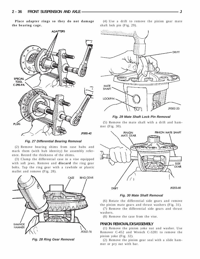
Place adapter rings so they do not damagethe bearing cage.
(2) Remove bearing shims from case hubs andmark them (with hub identity) for assembly refer-ence. Record the thickness of the shims.
(3) Clamp the differential case in a vise equippedwith soft jaws. Remove and discard the ring gearbolts. Tap the ring gear with a rawhide or plasticmallet and remove (Fig. 28).
(4) Use a drift to remove the pinion gear mateshaft lock pin (Fig. 29).
(5) Remove the mate shaft with a drift and ham-mer (Fig. 30).
(6) Rotate the differential side gears and removethe pinion mate gears and thrust washers (Fig. 31).
(7) Remove the differential side gears and thrustwashers.
(8) Remove the case from the vise.
PINION REMOVAL/DISASSEMBLY(1) Remove the pinion yoke nut and washer. Use
Remover C-452 and Wrench C-3281 to remove thepinion yoke (Fig. 32).
(2) Remove the pinion gear seal with a slide ham-mer or pry out with bar.
Fig. 27 Differential Bearing Removal
Fig. 28 Ring Gear Removal
Fig. 29 Mate Shaft Lock Pin Removal
Fig. 30 Mate Shaft Removal
2 - 36 FRONT SUSPENSION AND AXLE J
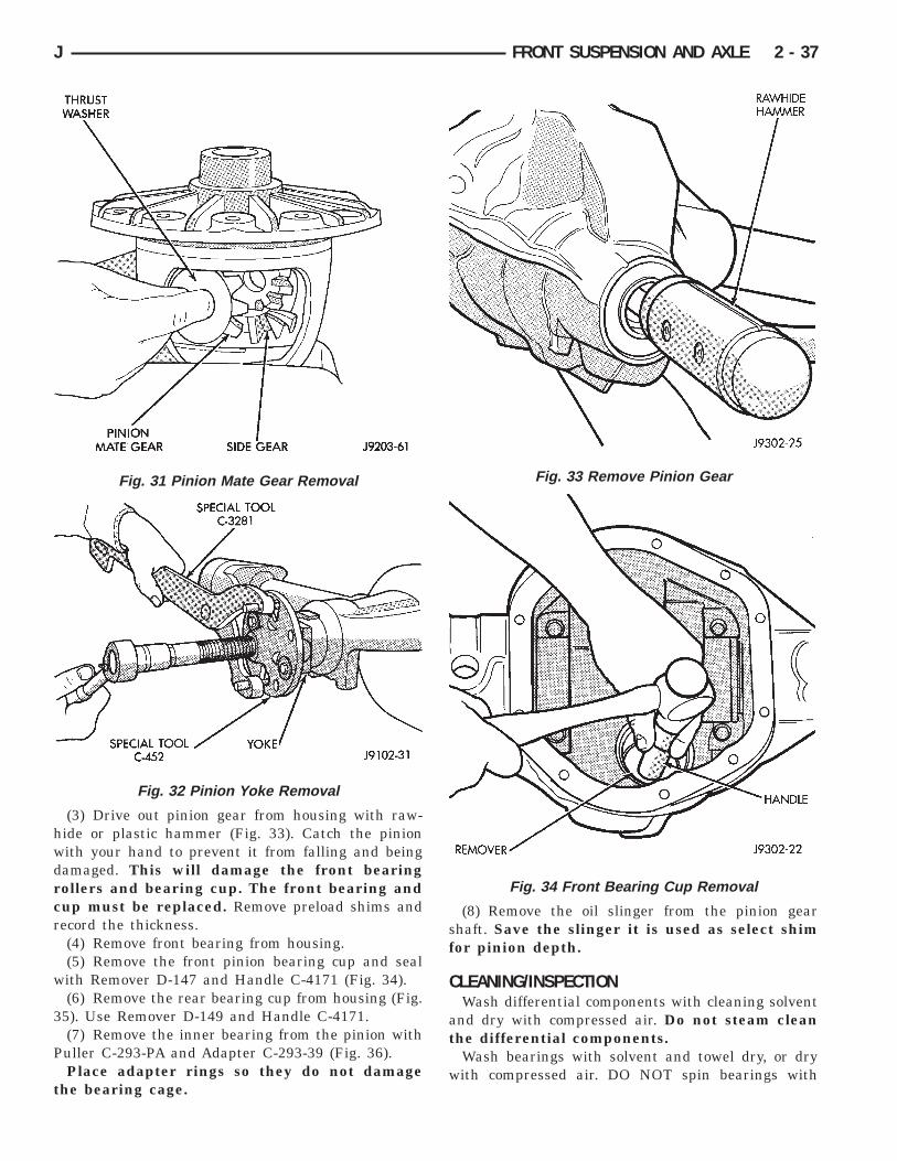
(3) Drive out pinion gear from housing with raw-hide or plastic hammer (Fig. 33). Catch the pinionwith your hand to prevent it from falling and beingdamaged. This will damage the front bearingrollers and bearing cup. The front bearing andcup must be replaced. Remove preload shims andrecord the thickness.
(4) Remove front bearing from housing.(5) Remove the front pinion bearing cup and seal
with Remover D-147 and Handle C-4171 (Fig. 34).(6) Remove the rear bearing cup from housing (Fig.
35). Use Remover D-149 and Handle C-4171.(7) Remove the inner bearing from the pinion with
Puller C-293-PA and Adapter C-293-39 (Fig. 36).Place adapter rings so they do not damage
the bearing cage.
(8) Remove the oil slinger from the pinion gearshaft. Save the slinger it is used as select shimfor pinion depth.
CLEANING/INSPECTIONWash differential components with cleaning solvent
and dry with compressed air. Do not steam cleanthe differential components.
Wash bearings with solvent and towel dry, or drywith compressed air. DO NOT spin bearings with
Fig. 31 Pinion Mate Gear Removal
Fig. 32 Pinion Yoke Removal
Fig. 33 Remove Pinion Gear
Fig. 34 Front Bearing Cup Removal
J FRONT SUSPENSION AND AXLE 2 - 37

compressed air. Cup and bearing must be re-placed as a matched sets only.
Clean axle shaft tubes and oil channels with cleancloth.
Inspect for;• Smooth appearance with no broken/dented sur-faces on the bearing rollers or the roller contact sur-faces.• Bearing cups must not be distorted or cracked.• Machined surfaces should be smooth and withoutany raised edges.
• Raised metal on shoulders of cup bores should beremoved with a hand stone.• Wear or damage to pinion gear mate shaft, piniongears, side gears and thrust washers. Replace as amatched set only.• Worn or chipped teeth to ring and pinion gears.• Damaged bolt threads to ring gear. Replaced as amatched set only.• Pinion yoke for cracks, worn splines, pitted areas,and a rough/corroded seal contact surface. Repair orreplace the as necessary.
DIFFERENTIAL ASSEMBLY
ASSEMBLY(1) Install the following components in the differ-
ential case (Fig. 37).• Differential side gears and thrust washers• Pinion gears and thrust washers• Pinion gear mate shaft (align holes in shaft andcase)
(2) Install and seat the locking roll pin in the dif-ferential case and mate shaft with a punch and ham-mer (Fig. 37). Peen metal part of case over pin in twoplaces 180 degrees apart.
If replacement gears and thrust washers wereinstalled, it is not necessary to measure thegear backlash. Correct fit is due to close ma-chining tolerances during manufacture.
(3) Invert the differential case and start two ringgear bolts. This will provide case-to-ring gear bolthole alignment.
(4) Install new ring gear bolts and alternatelytighten to 95-122 Nzm (70-90 ft. lbs.) torque (Fig. 38).
Fig. 35 Rear Bearing Cup Removal
Fig. 36 Inner Bearing Removal
Fig. 37 Mate Shaft Pin Installation
2 - 38 FRONT SUSPENSION AND AXLE J

(5) Lubricate all differential components with hy-poid gear lubricant.
PINION GEAR DEPTH INFORMATIONRing and pinion gears are supplied as matched sets
only. The identifying numbers for the ring and piniongear are etched into the face of each gear (Fig. 39). Aplus (+) number, minus (-) number or zero (0) isetched into the face of the pinion gear. This numberis the amount (in thousandths of an inch) the depthvaries from the standard depth setting of a pinionetched with a (0). The standard setting from the cen-terline of the ring gear to the back face of the pinionis 92.1 mm (3.625 inches) for Model 30 axles (Fig.40). The standard depth provides the best teeth con-tact pattern.
THE BUTTON END ON THE PINION GEARHEAD IS NO LONGER A MACHINED-TO-SPECIFI-CATIONS SURFACE. DO NOT USE THIS SUR-FACE FOR PINION DEPTH SET-UP ORCHECKING (Fig. 40).
Compensation for depth variance is achieved by aselected thickness oil slinger (production) or shims(service). The slinger is placed between the inner pin-ion bearing cone and gear head (Fig. 41). The shimpack is placed under the inner (rear) bearing cup forservice. To change the pinion adjustment, shims areavailable in thicknesses of 0.003, 0.005, and 0.010inch. The oil slinger or baffle must be measuredand the thickness included with the total shimpack.
Fig. 38 Ring Gear Bolt Installation
Fig. 39 Pinion Gear ID Numbers
Fig. 40 Pinion Gear Head
Fig. 41 Shim Locations
J FRONT SUSPENSION AND AXLE 2 - 39
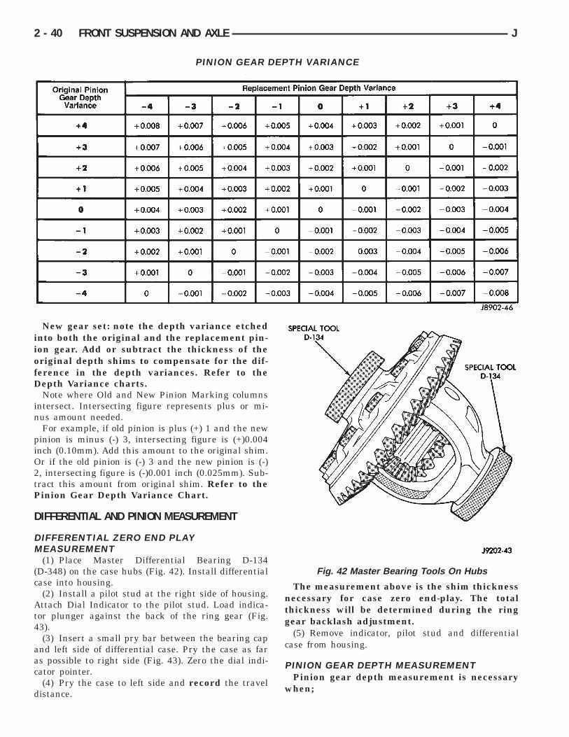
New gear set: note the depth variance etchedinto both the original and the replacement pin-ion gear. Add or subtract the thickness of theoriginal depth shims to compensate for the dif-ference in the depth variances. Refer to theDepth Variance charts.
Note where Old and New Pinion Marking columnsintersect. Intersecting figure represents plus or mi-nus amount needed.
For example, if old pinion is plus (+) 1 and the newpinion is minus (-) 3, intersecting figure is (+)0.004inch (0.10mm). Add this amount to the original shim.Or if the old pinion is (-) 3 and the new pinion is (-)2, intersecting figure is (-)0.001 inch (0.025mm). Sub-tract this amount from original shim. Refer to thePinion Gear Depth Variance Chart.
DIFFERENTIAL AND PINION MEASUREMENT
DIFFERENTIAL ZERO END PLAYMEASUREMENT
(1) Place Master Differential Bearing D-134(D-348) on the case hubs (Fig. 42). Install differentialcase into housing.
(2) Install a pilot stud at the right side of housing.Attach Dial Indicator to the pilot stud. Load indica-tor plunger against the back of the ring gear (Fig.43).
(3) Insert a small pry bar between the bearing capand left side of differential case. Pry the case as faras possible to right side (Fig. 43). Zero the dial indi-cator pointer.
(4) Pry the case to left side and record the traveldistance.
The measurement above is the shim thicknessnecessary for case zero end-play. The totalthickness will be determined during the ringgear backlash adjustment.
(5) Remove indicator, pilot stud and differentialcase from housing.
PINION GEAR DEPTH MEASUREMENTPinion gear depth measurement is necessary
when;
PINION GEAR DEPTH VARIANCE
Fig. 42 Master Bearing Tools On Hubs
2 - 40 FRONT SUSPENSION AND AXLE J

• Axle housing or differential case is replaced• Pinion select shim pack is unknown• Ring and pinion gears are replaced
Measurements are done with pinion cups and pin-ion bearings installed in housing. Take measure-ments with Pinion Gauge Set 6774, Pinion Block6733 and Dial Indicator C-3339 (Fig. 44).
(1) Install the pinion front bearing cup with In-staller D-144 and Handle C-4171 (Fig. 45).
(2) Install the bearing cup with Installer D-146and Driver Handle C-4171 (Fig. 46). Ensure cup iscorrectly seated.
(3) Assemble Pinion Gauge Set, Pinion Block andpinion bearings. Install assembly into differentialpinion gear bore and hand tighten cone (Fig. 47).
(4) Place Arbor Disc 6732 on Arbor D-115-3 and po-sition in the bearing cradles (Fig. 48). Install differ-ential bearing caps on Arbor Discs and tighten capssnug only.
Arbor Discs have different steps to fit otheraxle sizes. Pick correct size step for axle beingserviced.
(5) Firmly place Scooter Block and Dial Indicatoron pinion height block tool and zero the dial indicatorpointer.
(6) Slide the Scooter Block across the arbor while
Fig. 43 Differential Case End Play Measurement
Fig. 44 Pinion Gear Depth Gauge Tools
Fig. 45 Pinion Front Bearing Cup Installation
Fig. 46 Pinion Rear Bearing Cup Installation
J FRONT SUSPENSION AND AXLE 2 - 41

observing indicator (Fig. 49). Record the longesttravel distance, whether inward (-) or outward (+),indicated by the pointer.
The plunger travel, plus or minus the vari-ance etched in the gear, is the required thick-ness for the depth shims.
(7) Measure the thickness of each depth shim witha micrometer. Combine the shims necessary for totalrequired shim pack thickness. Include oil slingeror baffle thickness with the total shim packthickness.
(8) Remove the measurement tools from the differ-ential housing.
PINION GEAR ASSEMBLY/INSTALLATION(1) Remove rear pinion bearing cup with Remover
D-149 and Handle C-4171. Place shims (and baffle ifequipped) in the pinion gear rear bearing bore. In-stall the bearing cup with Installer D-146 and DriverHandle C-4171. Ensure cup is correctly seated.
(3) Install rear bearing and oil slinger on piniongear with Installer W-262 until completely seated(Fig. 50).
(4) Assemble preload shims onto pinion shaft.(5) Install pinion front bearing cone into cup and
end yoke thrust washer.(6) Apply a light coat of gear lubricant on lip of
new pinion seal. Install seal with Installer D-163 andHandle C-4171 (Fig. 51).
(7) Install pinion gear into differential housing.(9) Install yoke with Installer W-162-D and
Wrench C-3281 (Fig. 52).(10) Install the yoke washer and old nut on the
pinion gear. Use Flange Wrench C-3281 to retain theyoke (Fig. 53). Tighten nut to 216-352 Nzm (160-260ft.lbs.) torque.
Fig. 47 Pinion Height Block
Fig. 48 Gauge Tools In Housing
Fig. 49 Pinion Depth Measurement
Fig. 50 Pinion Rear Bearing Installation
2 - 42 FRONT SUSPENSION AND AXLE J

(11) Check bearing rotating torque with an inchpound torque wrench (Fig. 54).If torque to rotate iswithin specification, remove old nut and install newnut. The torque necessary to rotate the pinion gearshould be;• Original Bearings: 1 to 3 Nzm (10 to 20 in. lbs.).• New Bearings: 2 to 5 Nzm (15 to 35 in. lbs.).
(12) If rotating torque is high, add shims to de-crease torque. If rotating torque is low, remove shimsto increase torque.
DIFFERENTIAL SHIM PACK MEASUREMENT ANDADJUSTMENT
(1) Place Master Differential Bearing D-134(D-348) on the case hubs.
(2) Install a pilot stud at the left side of housing.Attach Dial Indicator to housing. Load the indicatorplunger against the back of the ring gear (Fig. 55).Ensure ring and pinion gear teeth are tightlymeshed. Zero the indicator.
Fig. 51 Pinion Seal Installation
Fig. 52 Pinion Yoke Installation
Fig. 53 Tightening Pinion Nut
Fig. 54 Check Pinion Gear Torque
J FRONT SUSPENSION AND AXLE 2 - 43
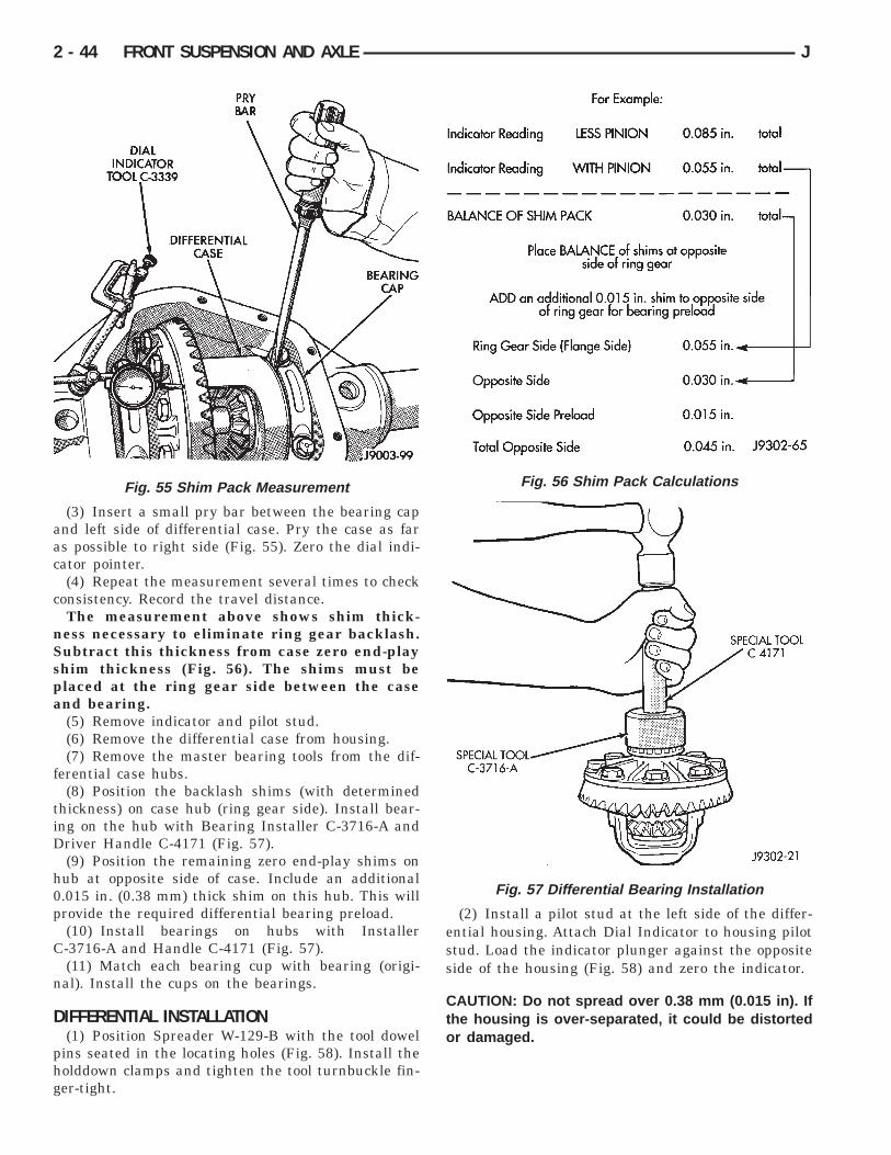
(3) Insert a small pry bar between the bearing capand left side of differential case. Pry the case as faras possible to right side (Fig. 55). Zero the dial indi-cator pointer.
(4) Repeat the measurement several times to checkconsistency. Record the travel distance.
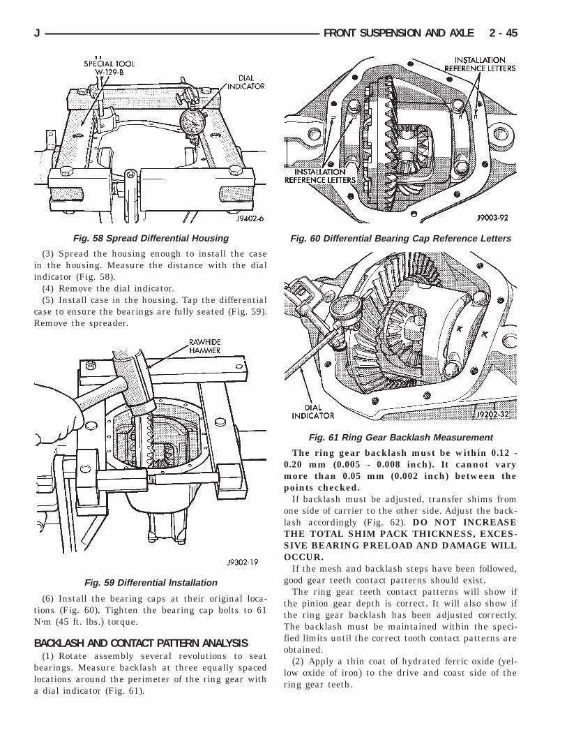
The measurement above shows shim thick-ness necessary to eliminate ring gear backlash.Subtract this thickness from case zero end-playshim thickness (Fig. 56). The shims must beplaced at the ring gear side between the caseand bearing.
(5) Remove indicator and pilot stud.(6) Remove the differential case from housing.(7) Remove the master bearing tools from the dif-
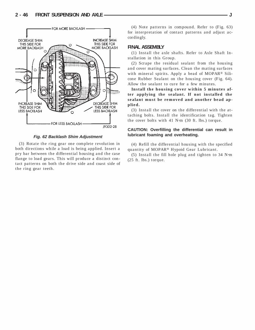
ferential case hubs.(8) Position the backlash shims (with determined
thickness) on case hub (ring gear side). Install bear-ing on the hub with Bearing Installer C-3716-A andDriver Handle C-4171 (Fig. 57).
(9) Position the remaining zero end-play shims onhub at opposite side of case. Include an additional0.015 in. (0.38 mm) thick shim on this hub. This willprovide the required differential bearing preload.
(10) Install bearings on hubs with InstallerC-3716-A and Handle C-4171 (Fig. 57).
(11) Match each bearing cup with bearing (origi-nal). Install the cups on the bearings.
DIFFERENTIAL INSTALLATION(1) Position Spreader W-129-B with the tool dowel
pins seated in the locating holes (Fig. 58). Install theholddown clamps and tighten the tool turnbuckle fin-ger-tight.
(2) Install a pilot stud at the left side of the differ-ential housing. Attach Dial Indicator to housing pilotstud. Load the indicator plunger against the oppositeside of the housing (Fig. 58) and zero the indicator.
CAUTION: Do not spread over 0.38 mm (0.015 in). Ifthe housing is over-separated, it could be distortedor damaged.
Fig. 55 Shim Pack Measurement Fig. 56 Shim Pack Calculations
Fig. 57 Differential Bearing Installation
2 - 44 FRONT SUSPENSION AND AXLE J
(3) Spread the housing enough to install the casein the housing. Measure the distance with the dialindicator (Fig. 58).
(4) Remove the dial indicator.(5) Install case in the housing. Tap the differential
case to ensure the bearings are fully seated (Fig. 59).Remove the spreader.
(6) Install the bearing caps at their original loca-tions (Fig. 60). Tighten the bearing cap bolts to 61Nzm (45 ft. lbs.) torque.
BACKLASH AND CONTACT PATTERN ANALYSIS(1) Rotate assembly several revolutions to seat
bearings. Measure backlash at three equally spacedlocations around the perimeter of the ring gear witha dial indicator (Fig. 61).
The ring gear backlash must be within 0.12 -0.20 mm (0.005 - 0.008 inch). It cannot varymore than 0.05 mm (0.002 inch) between thepoints checked.
If backlash must be adjusted, transfer shims fromone side of carrier to the other side. Adjust the back-lash accordingly (Fig. 62). DO NOT INCREASETHE TOTAL SHIM PACK THICKNESS, EXCES-SIVE BEARING PRELOAD AND DAMAGE WILLOCCUR.
If the mesh and backlash steps have been followed,good gear teeth contact patterns should exist.
The ring gear teeth contact patterns will show ifthe pinion gear depth is correct. It will also show ifthe ring gear backlash has been adjusted correctly.The backlash must be maintained within the speci-fied limits until the correct tooth contact patterns areobtained.
(2) Apply a thin coat of hydrated ferric oxide (yel-low oxide of iron) to the drive and coast side of thering gear teeth.
Fig. 58 Spread Differential Housing
Fig. 59 Differential Installation
Fig. 60 Differential Bearing Cap Reference Letters
Fig. 61 Ring Gear Backlash Measurement
J FRONT SUSPENSION AND AXLE 2 - 45
(3) Rotate the ring gear one complete revolution inboth directions while a load is being applied. Insert apry bar between the differential housing and the caseflange to load gears. This will produce a distinct con-tact patterns on both the drive side and coast side ofthe ring gear teeth.
(4) Note patterns in compound. Refer to (Fig. 63)for interpretation of contact patterns and adjust ac-cordingly.
FINAL ASSEMBLY(1) Install the axle shafts. Refer to Axle Shaft In-
stallation in this Group.(2) Scrape the residual sealant from the housing
and cover mating surfaces. Clean the mating surfaceswith mineral spirits. Apply a bead of MOPARt Sili-cone Rubber Sealant on the housing cover (Fig. 64).Allow the sealant to cure for a few minutes.
Install the housing cover within 5 minutes af-ter applying the sealant. If not installed thesealant must be removed and another bead ap-plied.
(3) Install the cover on the differential with the at-taching bolts. Install the identification tag. Tightenthe cover bolts with 41 Nzm (30 ft. lbs.) torque.
CAUTION: Overfilling the differential can result inlubricant foaming and overheating.
(4) Refill the differential housing with the specifiedquantity of MOPARt Hypoid Gear Lubricant.
(5) Install the fill hole plug and tighten to 34 Nzm(25 ft. lbs.) torque.
Fig. 62 Backlash Shim Adjustment
2 - 46 FRONT SUSPENSION AND AXLE J

Fig. 63 Gear Tooth Contact Patterns
J FRONT SUSPENSION AND AXLE 2 - 47

Fig. 64 Typical Housing Cover With Sealant
2 - 48 FRONT SUSPENSION AND AXLE J

AXLE SPECIFICATIONS
MODEL 30 FRONT AXLEAxle Type ........................................................HypoidLubricant................SAE Thermally Stable 80W-90Lube CapacityYJ .....................................................1.65 L (3.76 pts.)XJ .....................................................1.48 L (3.13 pts.)Axle Ratio...................................3.07 3.55 3.73 4.10Differential
Side Gear Clearance .0.12-0.20mm (0.005-0.008 in.)Ring GearDiameter .....................................18.09 cm (7.125 in.)Backlash.........................0-0.15 mm (0.005-0.008 in.)Pinion Std. Depth ...................92.1 mm (3.625 in.)Pinion Bearing PreloadOriginal Bearing ..................1-2 Nzm (10-20 in. lbs.)New Bearing......................1.5-4 Nzm (15-35 in. lbs.)
TORQUE SPECIFICATIONS
XJ FRONT SUSPENSION COMPONENTS
DESCRIPTION................................................TORQUEShock AbsorberUpper Nut ......................................11 Nzm (8 ft. lbs.)Lower Nut....................................23 Nzm (17 ft. lbs.)Suspension Arm UpperFront Nut.....................................74 Nzm (55 ft. lbs.)Rear Nut ......................................89 Nzm (66 ft. lbs.)Suspension Arm LowerFront and Rear Nut..................115 Nzm (85 ft. lbs.)Stabilizer BarClamp Bolt...................................54 Nzm (40 ft. lbs.)Link Upper Nut ..........................36 Nzm (27 ft. lbs.)Link Lower Nut ..........................95 Nzm (70 ft. lbs.)Track BarBall Stud Nut..............................81 Nzm (60 ft. lbs.)Axle Bracket Bolt......................100 Nzm (74 ft. lbs.)Track Bar BracketBolts............................................125 Nzm (92 ft. lbs.)Nut..............................................100 Nzm (74 ft. lbs.)Support Bolts...............................42 Nzm (31 ft. lbs.)
YJ FRONT SUSPENSION COMPONENTS
DESCRIPTION................................................TORQUEShock AbsorberUpper Nut......................................13 Nzm (9 ft. lbs.)
Lower Nut....................................61 Nzm (45 ft. lbs.)Stabilizer BarClamp Bolt...................................41 Nzm (30 ft. lbs.)Link Nut ......................................61 Nzm (45 ft. lbs.)Track BarFrame Bracket Nut.................142 Nzm (105 ft. lbs.)Axle Bracket Nut ......................100 Nzm (74 ft. lbs.)SpringU-Bolt Nut .................................122 Nzm (90 ft. lbs.)Front Shackle Bolt..................135 Nzm (100 ft. lbs.)Rear Pivot Bolt........................142 Nzm (105 ft. lbs.)
MODEL 30 AXLE
DESCRIPTION................................................TORQUEFill Hole Plug ...........................34 Nzm (25 ft. lbs.)Diff. Cover Bolt ........................41 Nzm (30 ft. lbs.)Bearing Cap Bolt .....................61 Nzm (45 ft. lbs.)Ring Gear Bolt .............95-122 Nzm (70-90 ft. lbs.)Shift Motor Bolt .........................11 Nzm (8 ft. lbs.)Axle Nut .................................237 Nzm (175 ft. lbs.)Wheel Brg. Bolt ......................102 Nzm (75 ft. lbs.)Lower Ball Stud .....................108 Nzm (80 ft. lbs.)Upper Ball Stud .....................101 Nzm (75 ft. lbs.)ABS Sensor Bolt ......................11 Nzm (96 in. lbs.)
J FRONT SUSPENSION AND AXLE 2 - 49