Jeep Cherokee XJ 1995-1999 Power Locks
12
POWER LOCKS CONTENTS page page DIAGNOSIS ............................. 2 GENERAL INFORMATION .................. 1 SERVICE PROCEDURES ................... 8 GENERAL INFORMATION Power locks are optional equipment on XJ (Chero- kee) models. Power windows and the keyless entry system are included on vehicles equipped with the power lock option. All doors and the liftgate can be locked and unlocked electrically by operating the switch on either front door panel, or by operating the lock and unlock buttons of the remote keyless entry transmitter. The power lock and keyless entry sys- tems operate with battery power supplied indepen- dent of the ignition switch. Following are general descriptions of the major components in the power lock system. Refer to Group 8W - Wiring Diagrams for complete circuit descrip- tions and diagrams. Refer to the owner’s manual for more information on the features and use of these systems. POWER LOCK SWITCH The power locks are controlled by a two-way switch mounted on the trim panel of each front door. The switch controls battery feed to the lock and unlock relays. The door lock switches can not be repaired. If faulty, the entire switch must be replaced. POWER LOCK/UNLOCK RELAYS The power lock and unlock relays are located in the relay center. The relay center is located on the lower instrument panel reinforcement behind the lower in- strument panel and just right of the steering column. The relays respond to inputs from the power lock switches and the keyless entry module by sending the correct battery and ground feeds to the lock mo- tors. The lock and unlock relays can not be repaired. If faulty, they must be replaced. POWER LOCK MOTOR The locks are actuated by a reversible motor mounted within each door. The motor direction is controlled by the battery and ground feeds from the power lock/unlock relays. The motor can not be re- paired. If faulty, the entire motor must be replaced. KEYLESS ENTRY TRANSMITTER The keyless entry transmitter is equipped with two buttons labeled Lock and Unlock. It is also designed to serve as a key fob and is equipped with a key ring. Each transmitter has a different vehicle access code, which must be programmed into the memory of the keyless entry module in the vehicle in order to oper- ate the locks. The operating range of the infrared transmitter signal is up to 4.75 meters (15 feet) from the receiver. The transmitter operates on two CR1616 3-volt (or equivalent) batteries. Typical battery life is from one to two years. KEYLESS ENTRY MODULE The keyless entry module is mounted in a housing on the headliner near the windshield between the sunvisors, or inside and towards the rear of the over- head console (if equipped). This module contains the keyless entry receiver and program logic for the key- less entry system. The keyless entry module has a memory function to retain the vehicle access code of at least one, and up to four transmitters. The module receives input from the remote keyless entry transmitter. In re- sponse to that input, it is programmed to control out- puts to the lock and unlock relays. The module can not be repaired and, if faulty, must be replaced. J POWER LOCKS 8P - 1
description
Manual service Jeep Cherokee XJ
Transcript of Jeep Cherokee XJ 1995-1999 Power Locks

POWER LOCKS
CONTENTS
page page
DIAGNOSIS . . . . . . . . . . . . . . . . . . . . . . . . . . . . . 2GENERAL INFORMATION . . . . . . . . . . . . . . . . . . 1
SERVICE PROCEDURES . . . . . . . . . . . . . . . . . . . 8
GENERAL INFORMATION
Power locks are optional equipment on XJ (Chero-kee) models. Power windows and the keyless entrysystem are included on vehicles equipped with thepower lock option. All doors and the liftgate can belocked and unlocked electrically by operating theswitch on either front door panel, or by operating thelock and unlock buttons of the remote keyless entrytransmitter. The power lock and keyless entry sys-tems operate with battery power supplied indepen-dent of the ignition switch.
Following are general descriptions of the majorcomponents in the power lock system. Refer to Group8W - Wiring Diagrams for complete circuit descrip-tions and diagrams. Refer to the owner’s manual formore information on the features and use of thesesystems.
POWER LOCK SWITCHThe power locks are controlled by a two-way switch
mounted on the trim panel of each front door. Theswitch controls battery feed to the lock and unlockrelays. The door lock switches can not be repaired. Iffaulty, the entire switch must be replaced.
POWER LOCK/UNLOCK RELAYSThe power lock and unlock relays are located in the
relay center. The relay center is located on the lowerinstrument panel reinforcement behind the lower in-strument panel and just right of the steering column.The relays respond to inputs from the power lockswitches and the keyless entry module by sendingthe correct battery and ground feeds to the lock mo-tors. The lock and unlock relays can not be repaired.If faulty, they must be replaced.
POWER LOCK MOTORThe locks are actuated by a reversible motor
mounted within each door. The motor direction is
controlled by the battery and ground feeds from thepower lock/unlock relays. The motor can not be re-paired. If faulty, the entire motor must be replaced.
KEYLESS ENTRY TRANSMITTERThe keyless entry transmitter is equipped with two
buttons labeled Lock and Unlock. It is also designedto serve as a key fob and is equipped with a key ring.Each transmitter has a different vehicle access code,which must be programmed into the memory of thekeyless entry module in the vehicle in order to oper-ate the locks. The operating range of the infraredtransmitter signal is up to 4.75 meters (15 feet) fromthe receiver.
The transmitter operates on two CR1616 3-volt (orequivalent) batteries. Typical battery life is from oneto two years.
KEYLESS ENTRY MODULEThe keyless entry module is mounted in a housing
on the headliner near the windshield between thesunvisors, or inside and towards the rear of the over-head console (if equipped). This module contains thekeyless entry receiver and program logic for the key-less entry system.
The keyless entry module has a memory functionto retain the vehicle access code of at least one, andup to four transmitters. The module receives inputfrom the remote keyless entry transmitter. In re-sponse to that input, it is programmed to control out-puts to the lock and unlock relays. The module cannot be repaired and, if faulty, must be replaced.
J POWER LOCKS 8P - 1

DIAGNOSIS
As a preliminary system diagnosis, note system op-eration while you actuate both the Lock and Unlockfunctions with the power lock switches and the key-less entry transmitter. Then, proceed as follows:• If system fails to function with either the switchesor the transmitter, see Power Lock System diagnosis.• If system functions with both switches, but not thetransmitter, see Keyless Entry Transmitter diagnosis.• If system functions with transmitter, but not withone or both switches, see Power Lock System diagno-sis.• If one lock fails to operate with the switches ortransmitter, see Power Lock Motor diagnosis.
POWER LOCK SYSTEM(1) Inspect fuse 13 in fuseblock module. Replace if
necessary. If OK, measure voltage at battery side offuse. There should be 12 volts. If not OK, repair openfrom Power Distribution Center.
(2) Remove door switch(es) and measure voltage atterminal 1. Meter should read battery voltage. If OK,go to next step. If not OK, repair open to fuse 9 infuseblock module.
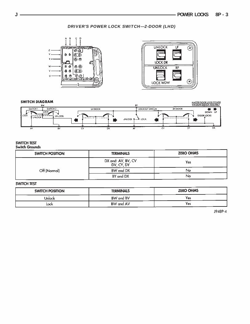
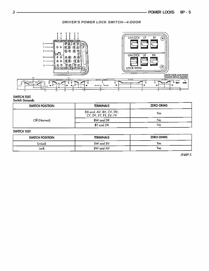
(3) Check door switch continuity as shown in theapplicable charts on the following pages. If OK, go tonext step. If not OK, replace switch.
(4) The power lock/unlock relays are in the relaycenter. The relay center is located on the lower in-strument panel reinforcement just right of the steer-ing column (Fig. 1). Remove both relays.
(5) Measure resistance between lock and unlock re-lay terminal 4 (87A) and ground. Meter should readzero ohms. If OK, go to next step. If not OK, repairopen to ground.
(6) Measure voltage at terminal 2 (87) of both thelock and unlock relays. Meter should read batteryvoltage. If OK, go to next step. If not OK, repair opento fuse 13 in fuseblock module.
(7) Measure resistance between lock and unlock re-lay terminal 5 (85) and ground. Meter should readzero ohms. If OK, go to next step. If not OK, repairopen to ground.
(8) Hold driver’s side switch in LOCK position.Measure voltage at lock relay terminal 3 (86). Metershould read battery voltage. If OK, go to next step. Ifnot OK, repair open to driver’s side switch.
(9) Hold driver’s side switch in UNLOCK position.Measure voltage at unlock relay terminal 3 (86).Meter should read battery voltage. If OK, go to nextstep. If not OK, repair open to driver’s side switch.
(10) Hold driver’s side switch in LOCK position.Measure voltage at lock relay terminal 1 (30). Metershould read battery voltage. If OK, go to next step. Ifnot OK, replace lock relay.
(11) Hold driver’s side switch in UNLOCK position.Measure voltage at unlock relay terminal 1 (30).Meter should read battery voltage. If OK, see PowerLock Motor diagnosis. If not OK, replace unlock re-lay.
Fig. 1 Power Lock/Unlock Relays
8P - 2 POWER LOCKS J
DRIVER’S POWER LOCK SWITCH—2-DOOR (LHD)
J POWER LOCKS 8P - 3

DRIVER’S POWER LOCK SWITCH—2-DOOR (RHD)
8P - 4 POWER LOCKS J
DRIVER’S POWER LOCK SWITCH—4-DOOR
J POWER LOCKS 8P - 5
PASSENGER’S POWER LOCK SWITCH
8P - 6 POWER LOCKS J
POWER LOCK MOTOR(1) Once it is determined which lock motor is inop-
erative, that motor can be tested. Disconnect the wireconnector at the motor. Apply 12 volts to the motorterminals to check its operation in one direction. Re-verse the polarity to check the operation in the otherdirection. If OK, repair circuits to power lock/unlockrelays as required. If not OK, replace the motor.
(2) If all lock motors are inoperative, the problemmay be caused by one shorted motor. Disconnecting ashorted motor will allow the good motors to operate.Disconnect each motor connector, one at a time, andre-check both lock and unlock functions while operat-ing the door lock switch. If disconnecting one motorcauses the other motors to become functional, goback to step 1 to test the disconnected motor.
KEYLESS ENTRY TRANSMITTER(1) Depress either transmitter button and note
whether red Light-Emitting Diode (LED) on trans-mitter case lights. If OK, go to next step. If not OK,replace batteries as described under Keyless EntryTransmitter in Service Procedures. Test transmitteroperation. If OK, discard faulty batteries. If not OK,go to next step.
(2) Perform transmitter program procedure withsuspect transmitter and another known good trans-mitter, as described in Service Procedures. Test oper-ation with both transmitters. If both transmitters failto operate power locks, see Keyless Entry Module di-agnosis. If known good transmitter operates powerlocks and suspect transmitter does not, replace faultytransmitter. Be certain to perform transmitter pro-gram procedure again when replacing faulty trans-mitter and to erase test transmitter access code fromkeyless entry module.
KEYLESS ENTRY MODULE(1) Check fuse 9 in fuseblock module. If OK, go to
next step. If not OK, replace fuse.(2) Check for battery voltage at fuse 9. If OK, go to
next step. If not OK, repair circuit from power distri-bution center.
(3) Access keyless entry module connectors as de-scribed in Keyless Entry Module Remove/Install.
(4) Unplug module connector from module. Checkconnector and receptacle in module for loose, cor-roded, or damaged terminals and pins. If OK, go tonext step. If not OK, repair as required.
(5) Probe connector cavity for module terminal 1and check for battery voltage. If OK, go to next step.If not OK, repair circuit to fuse 9 as required.
(6) Install a jumper wire from connector cavity formodule terminal 1 to connector cavity for module ter-minal 3. Doors should lock. If OK, go to step 8. If notOK, go to next step.
(7) Check for continuity between connector cavityfor module terminal 3 and lock relay terminal 3 (86).There should be continuity. If OK, replace lock relay.If not OK, repair circuit as required.
(8) Install a jumper wire from connector cavity formodule terminal 1 to connector cavity for module ter-minal 4. Doors should unlock. If OK, replace module.If not OK, go to next step.
(9) Check for continuity between connector cavityfor module terminal 4 and unlock relay terminal 3(86). There should be continuity. If OK, replace un-lock relay. If not OK, repair circuit as required.
J POWER LOCKS 8P - 7

SERVICE PROCEDURES
KEYLESS ENTRY TRANSMITTERTo replace transmitter batteries, separate transmit-
ter case by prying gently with a trim stick or otherwide flat-bladed tool at center seam (Fig. 2). Casesnaps open and shut. Replace with CR1616 3-voltbatteries or equivalent (Fig. 3).
TRANSMITTER PROGRAMMING PROCEDURE(1) Open the driver’s door of the vehicle. Leave it
open through the programming procedure.(2) Move the mechanical door lock lever to the
LOCK position.(3) Turn the ignition switch to the ON position.(4) Within 20 seconds, aim a transmitter at the
keyless entry module receiver dome and press theLOCK button for at least 5 seconds. Once the moduleaccepts the programming code, the driver’s door willunlock.
(5) Once the first transmitter has been pro-grammed, additional transmitters (up to 4) may be
programmed into the module. Within 20 seconds ofthe previous transmitter programming, move the me-chanical door lock lever to the LOCK position. Aimanother transmitter at the receiver dome and pressthe LOCK button for at least 5 seconds. The doorlock will cycle again.
(6) To lock the programmed codes into the module,the ignition switch must be turned OFF and backON within 20 seconds after programming the lasttransmitter’s code. At that time, all previous codesare erased from the module.
POWER LOCK SWITCH REMOVE/INSTALL(1) Remove the interior door latch release assem-
bly and control panel retaining screws (Fig. 4).
(2) Disconnect the control linkage and the wireharness connector.
(3) Remove the latch release and control panel as-sembly.
(4) The switch is retained to the panel with clips(Fig. 5). Push in on the retainer part of the clip andpry the clips.
(5) To install switch, position switch and press inretainer clips until they snap into position. Reverseremaining removal procedures to complete installa-tion.
POWER LOCK MOTOR REMOVE/INSTALL
DOORS(1) Remove interior door latch release assembly
and control panel retaining screws (Fig. 4).(2) Disconnect control linkage and wire harness
connector.(3) Remove latch release and control panel assem-
bly.
Fig. 2 Separate Transmitter Halves
Fig. 3 Battery Install
Fig. 4 Power Window/Lock Control Panel Remove/Install
8P - 8 POWER LOCKS J
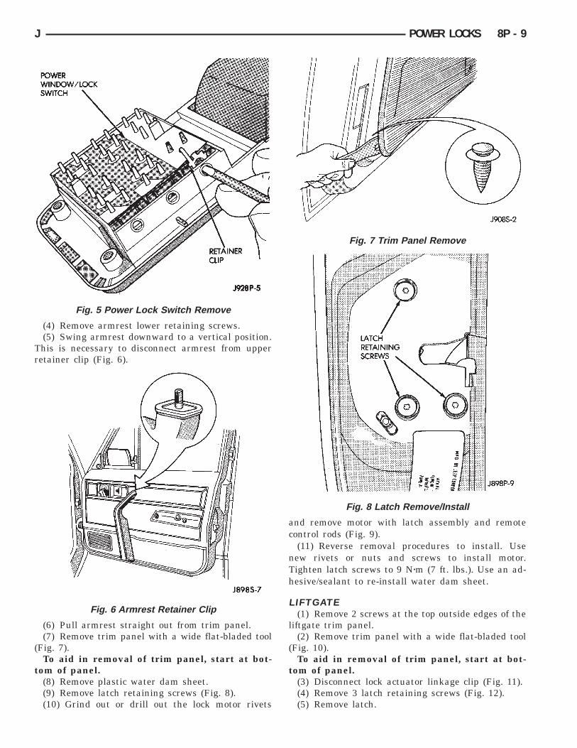
(4) Remove armrest lower retaining screws.(5) Swing armrest downward to a vertical position.
This is necessary to disconnect armrest from upperretainer clip (Fig. 6).
(6) Pull armrest straight out from trim panel.(7) Remove trim panel with a wide flat-bladed tool
(Fig. 7).To aid in removal of trim panel, start at bot-
tom of panel.(8) Remove plastic water dam sheet.(9) Remove latch retaining screws (Fig. 8).(10) Grind out or drill out the lock motor rivets
and remove motor with latch assembly and remotecontrol rods (Fig. 9).
(11) Reverse removal procedures to install. Usenew rivets or nuts and screws to install motor.Tighten latch screws to 9 Nzm (7 ft. lbs.). Use an ad-hesive/sealant to re-install water dam sheet.
LIFTGATE(1) Remove 2 screws at the top outside edges of the
liftgate trim panel.(2) Remove trim panel with a wide flat-bladed tool
(Fig. 10).To aid in removal of trim panel, start at bot-
tom of panel.(3) Disconnect lock actuator linkage clip (Fig. 11).(4) Remove 3 latch retaining screws (Fig. 12).(5) Remove latch.
Fig. 5 Power Lock Switch Remove
Fig. 6 Armrest Retainer Clip
Fig. 7 Trim Panel Remove
Fig. 8 Latch Remove/Install
J POWER LOCKS 8P - 9

(6) Drill out 2 rivets and remove motor.
(7) Reverse removal procedures to install. Tightenlatch screws to 9 Nzm (7 ft. lbs.).
KEYLESS ENTRY MODULE REMOVE/INSTALL
WITHOUT OVERHEAD CONSOLE(1) Remove 2 screws attaching receiver housing to
headlining (Fig. 13).
(2) Pull housing toward rear of vehicle to disen-gage clip.
(3) Disconnect module harness connector.(4) Remove circuit board from housing.
Fig. 9 Motor Remove/Install
Fig. 10 Liftgate Trim Panel Remove/Install
Fig. 11 Lock Actuator Linkage Clip
Fig. 12 Latch Assembly Remove/Install
Fig. 13 Remove/Install Keyless Entry Housing
8P - 10 POWER LOCKS J

(5) Reverse removal procedures to install.
WITH OVERHEAD CONSOLE(1) Remove screw forward of compass unit (Fig.
14).
(2) Flex housing outward while pressing upward todisengage housing from the rear bracket (arrow 1)(Fig. 14).
(3) Slide console rearward until the console de-taches from the front mounting bracket (arrow 2)(Fig. 14).
(4) While pressing up on rear of console (arrow 1),slide console forward holding front away from head-liner (arrow 2). Move console forward until the reardetaches from headliner and becomes free (Fig. 15).
(5) Disconnect wire harnesses from keyless entry
and compass (Figs. 16 and 17).(6) Pinch forward area of receiver cover and re-
lease clips. Slide cover out from under rib (Fig. 18).(7) Remove screw and printed circuit board.
Fig. 14 Remove/Install Overhead Console
Fig. 15 Remove/Install Overhead Console
Fig. 16 Disconnect Wire Harnesses
Fig. 17 Keyless Entry Harness Connector
Fig. 18 Keyless Entry Receiver Cover Remove/Install
J POWER LOCKS 8P - 11

(8) Reverse removal procedures to install. Be sureto flex housing outward near the keyless entry mod-ule until the console snaps onto the rear mountingbracket.
POWER LOCK/UNLOCK RELAY REMOVE/INSTALLThe power lock/unlock relays are located in the re-
lay center. The relay center is located on the lowerinstrument panel trim cover just right of the steeringcolumn (Fig. 19).
(1) Remove the appropriate relay from the relaycenter.
(2) Reverse removal procedure to install.
Fig. 19 Power Lock/Unlock Relays
8P - 12 POWER LOCKS J