Jay A. Kopp - National Highway Traffic Safety Administration · Jay A. Kopp . Legal Counsel ....
13
Jay A. Kopp Legal Department 314 West 90 th Street Minneapolis, Minnesota 55420 Tel (651) 407-3850 Fax (651) 407-3940 Mobile (651f) 587-0124 [email protected] VIA EMAIL ONLY [email protected] December 3, 2013 Associate Administrator for Enforcement Attn: ODI/Recall Management Division (NVS-215) 1200 Jersey Avenue, S.E. Washington, D.C. 20590 RE: Submission per 49 CFR 579.5(b) Dear Administrator: Pursuant to 49 CFR Part 579.5(b), enclosed is copies of three (3) service bulletins sent by Thermo King Corporation to its dealers in November of 2013. The service bulletins are related to safety recall campaigns #E12-023, #E12-041 and #E12-043. The purpose of the Thermo King campaign bulletins was to inform the Thermo King dealers that the internal reporting target end date for the respective campaigns has been extended until November 13, 2015 subject to federal regulations. Sincerely, THERMO KING CORPORATION Jay A. Kopp Jay A. Kopp Legal Counsel Enclosures
Transcript of Jay A. Kopp - National Highway Traffic Safety Administration · Jay A. Kopp . Legal Counsel ....
Jay A. Kopp Legal Department 314 West 90th Street Minneapolis, Minnesota 55420 Tel (651) 407-3850 Fax (651) 407-3940 Mobile (651f) 587-0124 [email protected]
VIA EMAIL ONLY [email protected]
December 3, 2013 Associate Administrator for Enforcement Attn: ODI/Recall Management Division (NVS-215) 1200 Jersey Avenue, S.E. Washington, D.C. 20590
RE: Submission per 49 CFR 579.5(b) Dear Administrator:
Pursuant to 49 CFR Part 579.5(b), enclosed is copies of three (3) service bulletins sent by Thermo King Corporation to its dealers in November of 2013. The service bulletins are related to safety recall campaigns #E12-023, #E12-041 and #E12-043. The purpose of the Thermo King campaign bulletins was to inform the Thermo King dealers that the internal reporting target end date for the respective campaigns has been extended until November 13, 2015 subject to federal regulations. Sincerely, THERMO KING CORPORATION Jay A. Kopp Jay A. Kopp Legal Counsel Enclosures

Date: November 20th, 2013
Subject: TK486 Engines - Fuel Delivery Guides - Safety Recall Campaign #12E-041
Bulletin Location: TSA Info Central\Bulletins\Campaign Bulletins
*Update: A new target end date for this campaign has been established, please see yellow highlight below.
Thermo King Corp. has decided that a defect which relates to motor vehicle safety exists in TK486 series diesel engines used in certain Thermo King climate control units for cargo trailers and generator sets. Cracks in the fuel delivery guides of these engines may result in fuel leakage, creating a potential fire hazard.
Customer Notification, Time Frame and Record Keeping
You should immediately notify all your customers who operate the Thermo King products listed below to schedule an appointment with an authorized Thermo King dealer to have this safety recall performed without charge to the customer. You must use the enclosed owner notification letter and envelopes for this purpose.
Each dealer should keep a copy of all correspondence relating to this recall, together with any written responses from customers. In addition, when requested by Thermo King Service or Warranty Departments, a dealer should forward copies of all correspondence to Thermo King so that Thermo King can monitor the success of this recall.
The target date for completion of this work and the filing of claims is November 13th, 2015 subject to federal regulation.
NOTE: It is a violation of federal law for a dealer to deliver a new motor vehicle or any new or used item of motor vehicle equipment covered by this notice under a sale or lease until the defect has been remedied.
Units Covered:
This recall affects TK486 series diesel engines used in the following Thermo King climate control units for cargo trailers and generator sets: SB-130 (TK486V), SB-230 (TK486V), SB-330 (TK486VH), Spectrum SB-30 (TK486V), Spectrum SB-50 (TK486V), Spectrum DE (TK486V), SB-200TG (TK486V), SB-400 (TK486V), SGCM-3000 (TK486VG2). Thermo King manufactured these units between December 9, 2011 and April 3, 2012. The recall also covers TK486V and TK486VH engines which Thermo King sold as replacement engines between January 3, 2012 and June 27, 2012.
Engine serial numbers covered by this recall are shown in the attached list.
CB570-1
Labor Hours: 1 Hour
Description: The fuel delivery guides in the affected TK486 engines will be replaced.
Parts List: Quantity Part Number Description
1 017087 Kit, Fuel Pump Delivery Guide
Procedure:
Replace fuel delivery guide in affected TK486 engines.
Filing Your Claim:
In “Claim Type” use “Field Modification”
Input the “Unit Serial Number”. If “Unit Serial Number” is not recognized in TAVANT as being qualified for this Campaign, contact the Thermo King Warranty Department to ensure the “Engine Serial Number” is registered to the unit being repaired.
Select the appropriate Field Modification number if not populated
Input your “Dealer Reference Number” in the “Work order Number” field
Input the “Hours In Service/Energy Units”
Input the “Repair date” this is the repair completion date
Leave the SMR and Commercial Policy boxes UNCHECKED
Depress “Continue”
Double check all the parts are accurate
Fill in the “Condition Found” and “Work Performed”
Attach any pertinent documents
The rest of this page will be completed automatically. The claim is complete and ready to validate and submit.
Attachments:
List of affected serial numbers
Delivery Valve Replacement on Field Units (Dated: October 15, 2012)
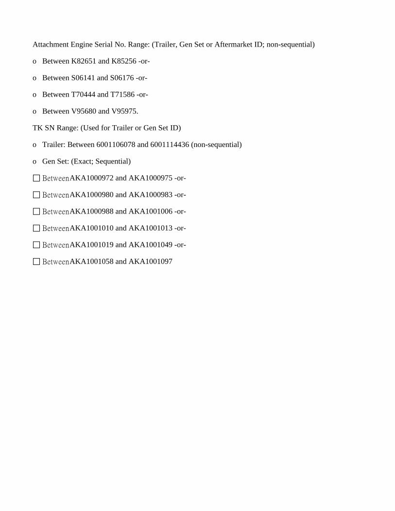
Attachment Engine Serial No. Range: (Trailer, Gen Set or Aftermarket ID; non-sequential)
o Between K82651 and K85256 -or-
o Between S06141 and S06176 -or-
o Between T70444 and T71586 -or-
o Between V95680 and V95975.
TK SN Range: (Used for Trailer or Gen Set ID)
o Trailer: Between 6001106078 and 6001114436 (non-sequential)
o Gen Set: (Exact; Sequential)
Between AKA1000972 and AKA1000975 -or-
Between AKA1000980 and AKA1000983 -or-
Between AKA1000988 and AKA1001006 -or-
Between AKA1001010 and AKA1001013 -or-
Between AKA1001019 and AKA1001049 -or-
Between AKA1001058 and AKA1001097

Delivery Valve Replacement on Field Units Date: October 15, 2012
Purpose: This document was created to instruct a field technician on how to replace four delivery valves in a Yanmar injection pump. The delivery valve guides installed in the injection pump have the potential to crack and cause a fuel leak. Note: If the unit serial number does not fall into the range listed this procedure should not be preformed Parts Required: 1 kit P/N 017087per engine 4 Delivery valve assemblies 4 Copper sealing washers Contact service parts to procure these parts.
Engine Parts removal: Step 1: Use compressed air/blow gun to clean sand/debris from around injection pump and fuel injector high pressure lines. Step 2: Place rags on Injection pump to catch any dripping fuel during disassembly
Step 3: Remove top three bolts and loosen bottom mount bolt on high speed solenoid. This will allow enough room to remove the high pressure injection lines.
Step 4: Remove the breather pipe from the valve cover. Bend it out of the way so the injector lines can be accessed for removal.
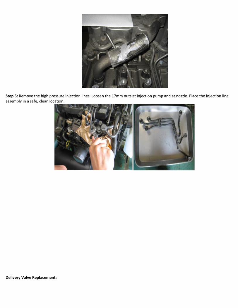
Step 5: Remove the high pressure injection lines. Loosen the 17mm nuts at injection pump and at nozzle. Place the injection line assembly in a safe, clean location.
Delivery Valve Replacement:

Step 1: Use a 14mm deep well socket to loosen delivery valve holder. Loosen holders 2 turns each then carefully clean up any paint chips/debris from top of injection pump
Step 2: Loosen delivery valve holder with fingers one by one. Remove holder by tilting a little so the delivery valve assembly stays in holder when removed.
Step 3: Remove copper sealing washer from hydraulic head using 90° pick.
Step 4: Remove old delivery valve assembly from delivery valve holder and place in bag with copper sealing washer. Please provide pump number, engine serial number, and replacement date, inside of bag with used parts. Return removed parts to Thermo King Warranty. Top spring will be re-used with new delivery valves.
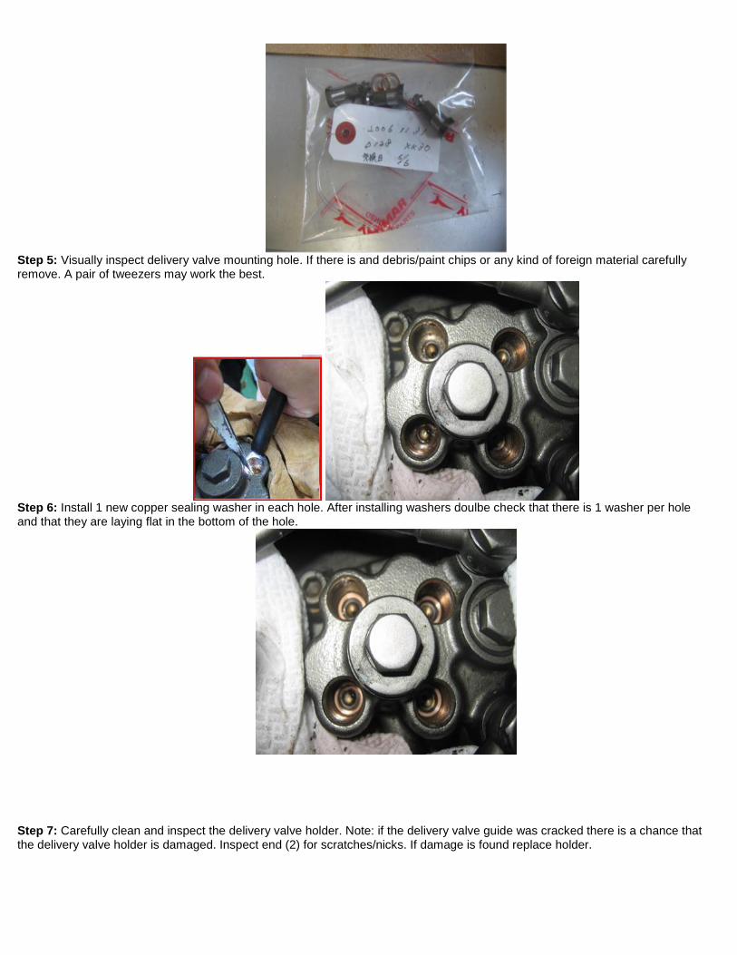
Step 5: Visually inspect delivery valve mounting hole. If there is and debris/paint chips or any kind of foreign material carefully remove. A pair of tweezers may work the best.
Step 6: Install 1 new copper sealing washer in each hole. After installing washers doulbe check that there is 1 washer per hole and that they are laying flat in the bottom of the hole.
Step 7: Carefully clean and inspect the delivery valve holder. Note: if the delivery valve guide was cracked there is a chance that the delivery valve holder is damaged. Inspect end (2) for scratches/nicks. If damage is found replace holder.
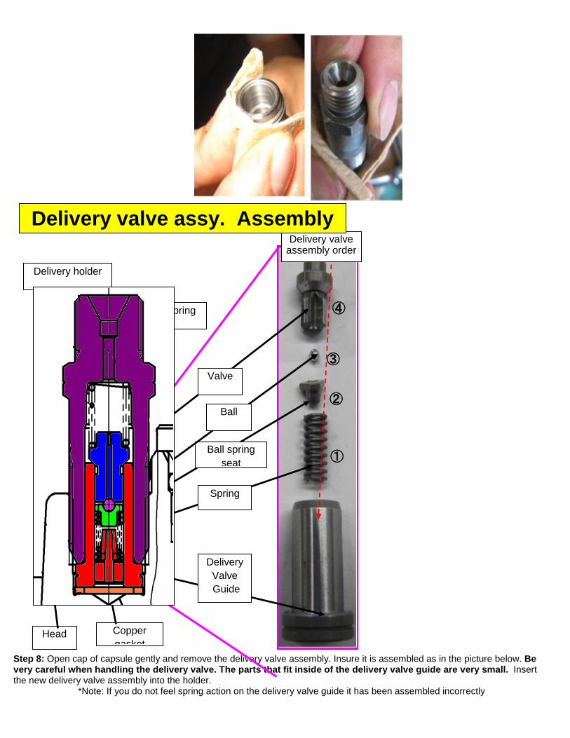
Step 8: Open cap of capsule gently and remove the delivery valve assembly. Insure it is assembled as in the picture below. Be
very careful when handling the delivery valve. The parts that fit inside of the delivery valve guide are very small. Insert the new delivery valve assembly into the holder.
*Note: If you do not feel spring action on the delivery valve guide it has been assembled incorrectly
Copper gasket
Delivery Valve Guide
Spring
Ball spring seat
Ball
Valve
①
②
③
④
Delivery valve assembly order
Delivery holder
Delivery spring
Head
Delivery valve assy. Assembly
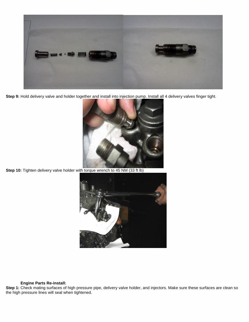
Step 9: Hold delivery valve and holder together and install into injection pump. Install all 4 delivery valves finger tight.
Step 10: Tighten delivery valve holder with torque wrench to 45 NM (33 ft lb)
Engine Parts Re-install: Step 1: Check mating surfaces of high pressure pipe, delivery valve holder, and injectors. Make sure these surfaces are clean so the high pressure lines will seal when tightened.
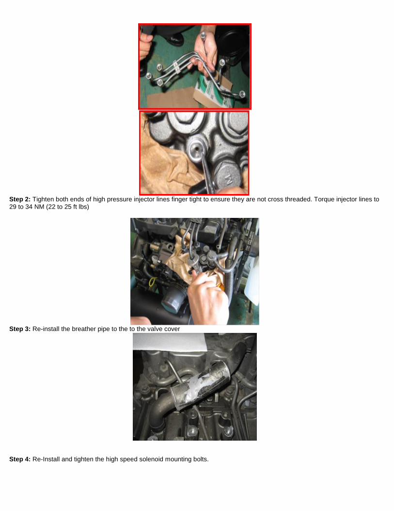
Step 2: Tighten both ends of high pressure injector lines finger tight to ensure they are not cross threaded. Torque injector lines to 29 to 34 NM (22 to 25 ft lbs)
Step 3: Re-install the breather pipe to the to the valve cover
Step 4: Re-Install and tighten the high speed solenoid mounting bolts.

Step 5: Degrease pump and engine with cleaning fluid
Step 6: re-paint surfaces that are missing paint
Step 7: Use a marker to put a line on the top of the distribution shaft plug to indicate the rework has been completed

Step 8: Start unit to verify proper operation and check for fuel leaks.