j HANDBOOK - Triumph 675 · A Cautic Index Foreword FOREWORD This handbook contains information on...
117
j OWNERS HANDBOOK
Transcript of j HANDBOOK - Triumph 675 · A Cautic Index Foreword FOREWORD This handbook contains information on...

j OWNERS HANDBOOK
REPORTING SAFETY DEFECTS!
If you believe your vehicle has a defect which could cause a crash or could cause injury or death, you should immediately inform the National Highway Traffic Safety Administration (NHTSA) in addition to notifying Triumph Motorcycles America Limited, 403 Dividend Drive, Peachtree City, 30269 Georgia. Telephone (770) 631 9500. If NHTSA receives similar complaints, it may open an investigation, and if it finds that a safety defect exists in a group of vehicles, it may order a -
recall and remedy campaign. However NHTSA cannot become involved i
in individual problems between you, your dealer, or Triumph Motorcycles ,
America Limited. I To contact NHTSA, you may either call the Auto Safety Hotline toll-free at
1-800-424-9393 (or 366-0123 in Washington, DC area) or write to: NHTSA, U.S. Department of Transportation, Washington, DC 20590. You can also obtain other information about motor vehicle safety from the Hotline.
A Cautic
Index Foreword
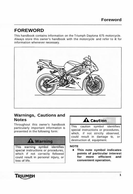
FOREWORD This handbook contains information on the Triumph Daytona 675 motorcycle. Always store this owner's handbook with the motorcycle and refer to it for information whenever necessary.
This page intentionally left blank
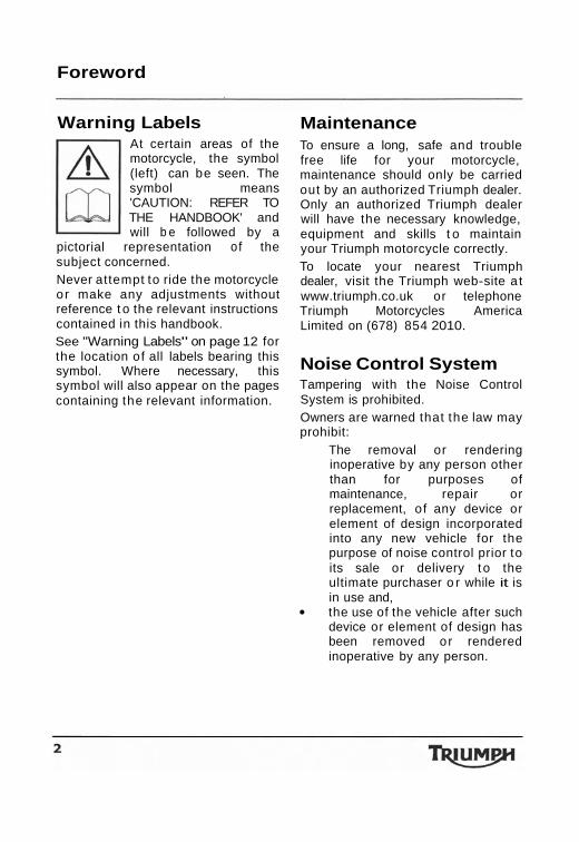
Warnings, Cautions and Notes Throughout this owner's handbook particularly important information is presented in the following form:
This warning symbol identifies
This caution symbol identifies special instructions or procedures, which, if not strictly observed, could result in damage to, or destruction of, equipment.
NOTE This note symbol indicates points of particular interest for more efficient and convenient operation.
Foreword
Warning Labels At certain areas of the motorcycle, the symbol (left) can be seen. The symbol means 'CAUTION: REFER TO THE HANDBOOK' and will b e followed by a
pictorial representation of the subject concerned. Never attempt to ride the motorcycle or make any adjustments without reference t o the relevant instructions contained in this handbook. See "Warning Labels" on page 12 for the location of all labels bearing this symbol. Where necessary, this symbol will also appear on the pages containing the relevant information.
Maintenance To ensure a long, safe and trouble free life for your motorcycle, maintenance should only be carried out by an authorized Triumph dealer. Only an authorized Triumph dealer will have the necessary knowledge, equipment and skills t o maintain your Triumph motorcycle correctly. To locate your nearest Triumph dealer, visit the Triumph web-site a t www.triumph.co.uk or telephone Triumph Motorcycles America Limited on (678) 854 2010.
Noise Control System Tampering with the Noise Control System is prohibited. Owners are warned that the law may prohibit:
The removal or rendering inoperative by any person other than for purposes of maintenance, repair or replacement, of any device or element of design incorporated into any new vehicle for the purpose of noise control prior to its sale or delivery t o the ultimate purchaser o r while it is in use and, the use of the vehicle after such device or element of design has been removed or rendered inoperative by any person.
Index Foreword
Fuel, 110 Fuel Requirement, 40
Filling the Fuel Tank, 42 Fuel Grade, 40 Fuel Tank Cap, 42
Fuel System, 110 Fuse Box, 98 G Gear Change Lights, 28 Gears
Changing Gears, 52 H Handlebar Switches
Left, 39 Right, 38
Headlights, 100 Adjustment, 100 Bulb Replacement, 101 Position Lamp, 102
I Ignition, 110
Key, 36 Switch/Steering Lock, 36
Instrument Panel Layout, 20 L Lap Timer, 24 License Plate Light, 103 Lubrication, 109 0 Odometer/Trip Meter, 21 P Performance, 109 R Rear Light, 103 Rear Seat, 44 Rider's Seat, 44
S Safety, 5
Daily Checks, 46 Fuel and Exhaust Fumes, 5 Handlebars and Footrests, 11 Helmet and Clothing, 6 Maintenance/Equipment, 8 Motorcycle, 5 Parking, 7 Parts and Accessories, 7 Riding, 9
Seat Lock, 44 Speedometer, 21 Stand, 43
Side Stand, 43 Steering/Wheel Bearings, 86
Inspection, 86 Storage
Preparation after Storage, 107
Preparation for Storage, 107 T Tachometer, 21 Throttle Control, 74 Tightening Torques, 111 Tires, 92, 11 1
Inflation Pressures, 92 Minimum Tread Depth, 93 Replacement, 94
Tool Kit, 43 Transmission, 11 0 v Vehicle Identification Number, 17 W Warning Lights, 34 Warnings
Owner's Handbook Thank you for choosing a Triumph motorcycle. This motorcycle is the product of Triumph's use of proven engineering, exhaustive testing, and continuous striving for superior reliability, safety and performance. Please read this owner's handbook before riding in order to become thoroughly familiar with the correct operation of your motorcycle's controls, its features, capabilities and limitations. This manual includes safe riding tips, but does not contain all the techniques and skills necessary to ride a motorcycle safely. Triumph strongly recommends that all riders undertake a safety course approved by the Motorcycle Safety Foundation to ensure safe operation of this motorcycle. Information about the nearest Motorcycle Safety Foundation course to you can be obtained by calling the following nationwide toll free number: 800- 447-4700, or by writing to the Motorcycle Safety Foundation at: 2, Jenner Street, Irvine, California 92718. To ensure a long and trouble free life for your motorcycle, maintenance should be carried out as described in this manual by an authorized Triumph dealer.
A warning This owner's handbook. and all other instructions that arb supplied with your motorcycle, should be considered a permanent part of your motorcycle and should remain with it even if your motorcycle is subsequently sold. All riders must read this owner's handbook and all other instructions which are supplied with your motorcycle, before riding, in order to become thoroughly familiar with the correct operation of your motorcycle's controls, its features, capabilities and limitations. Do not lend your motorcycle to others as riding when not familiar with your motorcycle's controls, features, capabilities and limitations can lead to an accident.
Foreword
Information The information contained in this publication is based on the latest information available at the time of printing. Triumph reserves the right to make changes at any time without prior notice, or obligation. Not to be reproduced wholly or in part without the written permission of Triumph Motorcycles America Limited. O Copyright 2006 Triumph Motorcycles America Limited. Publication part number 3851706 issue 2.
Table of Contents This handbook contains a number of different sections. The table of contents below will help you find the beginning of each section where, in the case of the major sections, a further table of contents will help you find the specific subject required. Foreword . . . . . . . . . . . . . . . . . . . . . . . . . . . . . . . . . . . . . . . . . . . . . . . 1 Warning Labels . . . . . . . . . . . . . . . . . . . . . . . . . . . . . . . . . . . . . . . . .12 Parts Identification . . . . . . . . . . . . . . . . . . . . . . . . . . . . . . . . . . . . . . .14
Serial Numbers . . . . . . . . . . . . . . . . . . . . . . . . . . . . . . . . . . . . . . . . .17 General Information . . . . . . . . . . . . . . . . . . . . . . . . . . . . . . . . . . . . . .19 How to Ride the Motorcycle . . . . . . . . . . . . . . . . . . . . . . . . . . . . . . . . .49
Accessories, Loading and Passengers. . . . . . . . . . . . . . . . . . . . . . . . . . .58 Maintenance and Adjustment . . . . . . . . . . . . . . . . . . . . . . . . . . . . . . . .63 Storage . . . . . . . . . . . . . . . . . . . . . . . . . . . . . . . . . . . . . . . . . . . . . . 107 Specifications . . . . . . . . . . . . . . . . . . . . . . . . . . . . . . . . . . . . . . . . . .I09
Foreword - Safety First
FOREWORD - SAFETY FIRST
The Motorcycle Fuel and Exhaust Fumes
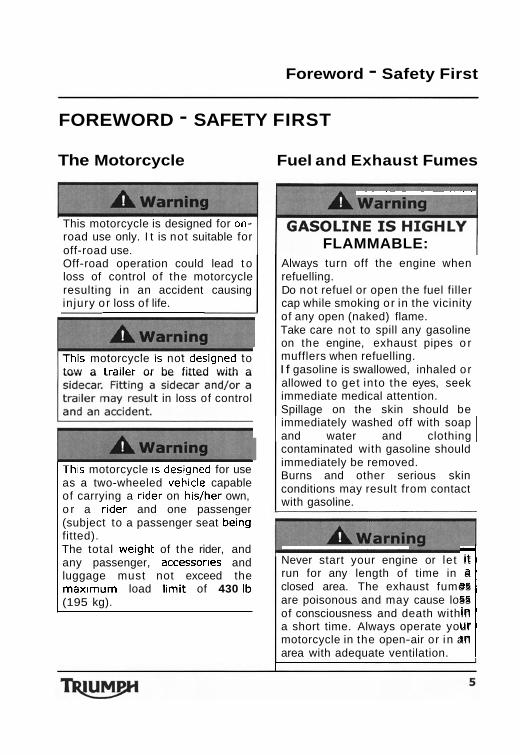
This motorcycle is designed for on- road use only. I t is not suitable for off-road use. Off-road operation could lead t o loss of control of the motorcycle resulting in an accident causing injury or loss of life.
Thls motorcycle IS not deslgned to tow a trader or be fitted with a
t in loss of control
Thls motorcycle IS des~gned for use as a two-wheeled vehlcle capable of carrying a rlder on h~s/her own, o r a rlder and one passenger (subject to a passenger seat belng fitted). The total we~ght of the rider, and any passenger, accessorles and luggage must not exceed the maxlmum load llmit of 430 1b (195 kg).
- - - - - - --- -- - -
FLAMMABLE: Always turn off the engine when refuelling. Do not refuel or open the fuel filler cap while smoking or in the vicinity of any open (naked) flame. Take care not to spill any gasoline on the engine, exhaust pipes o r mufflers when refuelling. I f gasoline is swallowed, inhaled or allowed to get into the eyes, seek immediate medical attention. Spillage on the skin should be immediately washed off with soap 1 and water and clothing I contaminated with gasoline should immediately be removed. Burns and other serious skin conditions may result from contact with gasoline. -
Never start your engine or let i t run for any length of time in a closed area. The exhaust fumes are poisonous and may cause loss of consciousness and death within a short time. Always operate your motorcycle in the open-air or in an area with adequate ventilation. 1
Foreword - Safety First
Safety Helmet and Clothing
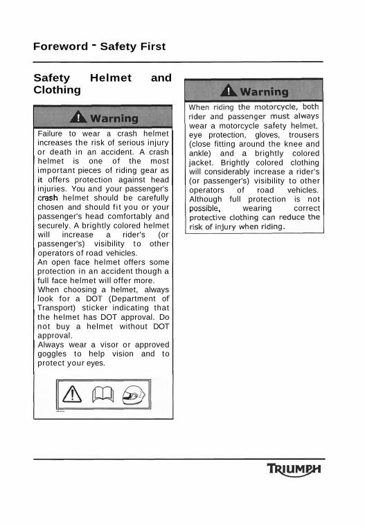
Failure to wear a crash helmet increases the risk of serious injury or death in an accident. A crash helmet is one of the most important pieces of riding gear as it offers protection against head injuries. You and your passenger's crash helmet should be carefully chosen and should f i t you or your passenger's head comfortably and securely. A brightly colored helmet will increase a rider's (or passenger's) visibility t o other operators of road vehicles. An open face helmet offers some protection in an accident though a full face helmet will offer more. When choosing a helmet, always look for a DOT (Department of Transport) sticker indicating that the helmet has DOT approval. Do not buy a helmet without DOT approval. Always wear a visor or approved goggles to help vision and to protect your eyes.
wear a motorcycle safety helmet, eye protection, gloves, trousers (close fitting around the knee and ankle) and a brightly colored jacket. Brightly colored clothing will considerably increase a rider's (or passenger's) visibility to other operators of road vehicles. Although full protection is not possible, wearing correct
Foreword - Safety First
Parking Parts and Accessories
Always turn off the engine an
the risk of use of the motorc by unauthorized or untrai persons is reduced. When parking the motorcycle
ed parts, accessories 'ons for any Triumph re those which carry ph approval and are
iumph does not accept any iability whatsoever for defects aused by the fitting of non- pproved parts, accessories or onversions or the fitting o f any pproved parts, accessories or onversions by non-approved
n particular, it is extremely azardous to fit o r replace parts or
essories whose fitting requires dismantling of, or addition to, er the electrical or fuel systems
any such modification could se a safety hazard.
e fitting of any non-approved arts, accessories or conversions
cle operation that may an accident causing injury
Foreword - Safety First
Maintenance/ Equipment
onsult your authorized Triumph ealer whenever there is doubt as o the correct or safe operation of
s Triumph motorcycle. member that continued eration of an incorrectly rforming motorcycle may
ggravate a fault and may als
aximum limit (when the bank le indicator is worn to a mum of 0.19 in (5 mm) in th) will allow the motorcycle t o banked to an unsafe angle.
erefore, always replace the bank ngle indicator pegs when they are
worn t o 0.19 in (5 mm) in length. Banking to an unsafe angle may cause instability, loss o f
I
Ensure all equipment that IS
requ~red by law is Installed and functioning correctly. The removal or alteration of the motorcycle's lights, mufflers, emission or noise control systems can violate the law. Incorrect or improper modification may adversely affect the handling, stability or other aspect of the motorcycle operation, which may result in an accident causing injury or death.
acc~dent, col l~s~on or fall, ~t must be taken to an authorized Triumph
cause damage to
may cause a a t may result in
Foreword - Safety First
Riding
Never ride the motorcycle when fatigued o r under the influence of alcohol or other drugs. Riding when under the influence of alcohol or other drugs is illegal. Riding when fatigued or under the influence of alcohol or other drugs reduces the rider's ability to maintain control of motorcycle and
operate the motorcycle. Operation of the motorcycle without a licence is illegal and could lead to prosecution. I n addition, operation without a licence is dangerous and may lead to loss of motorcycle control and an accident.
the protective equipment mentioned elsewhere in this
. Remember, in an , a motorcycle does not same impact protection as
A w a r n i r Th~s Trlumph motorcycle should be operated w~ th in the legal speed l ~ m ~ t s for the particular road travelled. Operating a motorcycle a t h ~ g h speeds can be potentially dangerous since the t ime available to react to given traffic situations is greatly reduced as road speed increases. Always reduce speed in potentially hazardous driving conditions such as bad weather or heavy traffic. -
external forces whlch may cause an accident. These forces include but are not limited to:
Wind draft from passing
Uneven o r holed road
Bad weather. Rider error.
ughly famlliar with and operating
Foreword - Safety First
'MOTORCYCLE SAFEW', 'YOU AN YOUR MOTORCYCLE, RIDING TIP and also read and become familia
the contents of RCYCLE HANDBOOK for y
A weave is a relatively slow oscillation of the rear o f the motorcycle, while a wobble is a rapid, possibly strong shaking of the handlebar. These are related but distinct stability problems usually caused by excessive weight in the wrong place, o r by a mechanical problem such as worn or loose bearings or under-inflated or unevenly worn tires. Your solution to both situations is the same. Keep a f irm hold on the handlebars without locking arms or fighting the steering. Smoothly ease off the throttle to slow gradually. Do not apply the brakes, and do not accelerate t o t ry t o stop the wobble or weave. I n some cases, it helps to shift your body weight forward by leaning over the
opyright @ 2005 Motorcycle
Foreword - Safety First
Handlebars and Footrests
otorcycle will be adversely ffected if the rider removes his
motorcycle components and will also reduce the risk of injury from
Warning Labels
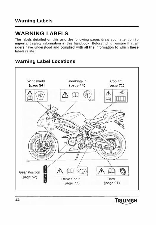
WARNING LABELS The labels detailed on this and the following pages draw your attention t o important safety information in this handbook. Before riding, ensure that all riders have understood and complied with all the information to which these labels relate.
Warning La be1 Locations
Windshield Breaking-In Coolant (page 84) (page 44) (page 71)
Gear Position
Warning Labels
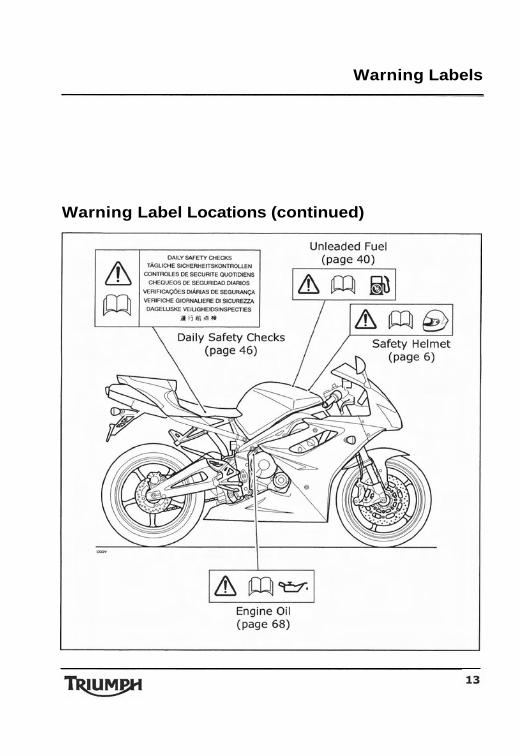
Warning Label Locations (continued)
Parts Identification
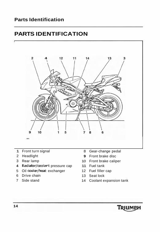
PARTS IDENTIFICATION
I
1 Front turn signal 8 Gear-change pedal 2 Headlight 9 Front brake disc 3 Rear lamp 10 Front brake caliper 4 Radiator/coolant pressure cap 11 Fuel tank 5 Oil cooler/heat exchanger 12 Fuel filler cap 6 Drive chain 13 Seat lock 7 Side stand 14 Coolant expansion tank
Parts Identification
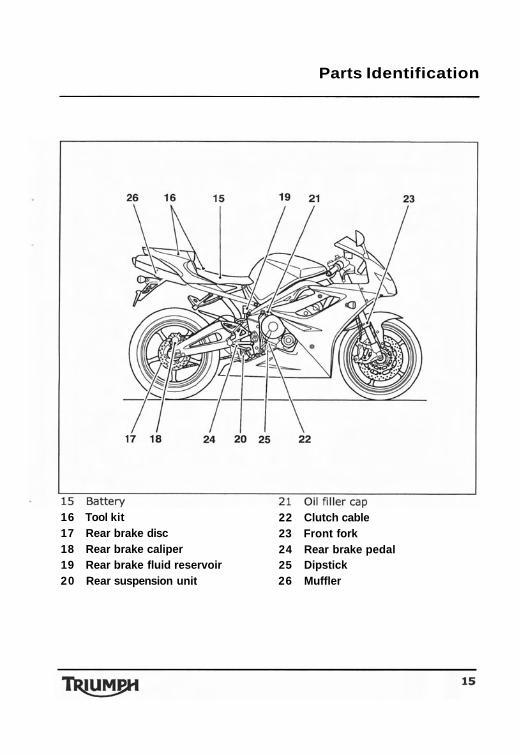
16 Tool kit 22 Clutch cable 17 Rear brake disc 23 Front fork 18 Rear brake caliper 24 Rear brake pedal 19 Rear brake fluid reservoir 25 Dipstick 20 Rear suspension unit 26 Muffler
Parts Identification
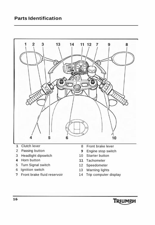
1 Clutch lever 8 Front brake lever 2 Passing button 9 Engine stop switch 3 Headlight dipswitch 10 Starter button 4 Horn button 11 Tachometer 5 Turn Signal switch 12 Speedometer 6 Ignition switch 13 Warning lights 7 Front brake fluid reservoir 14 Trip computer display
Serial Numbers
SERIAL NUMBERS
Vehicle Identification Engine Serial Number Number (V.I.N.)
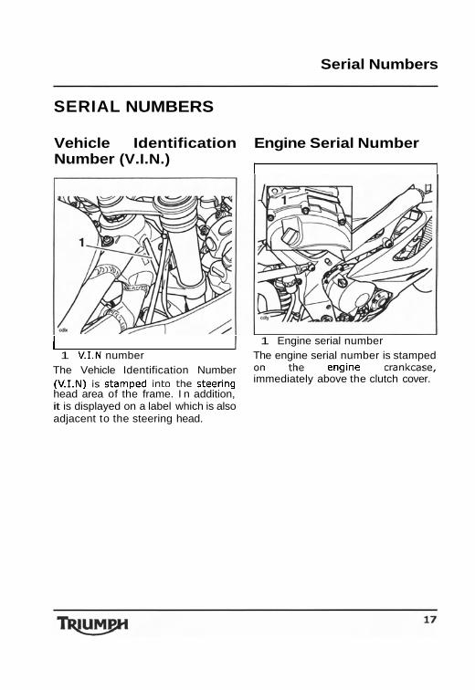
( 1 1 Engine serial number 1 V.1.N number The engine serial number is stamped
The Vehicle Identification Number 0" the engine cmnkcase, (v.1.~) is stamped into the steering immediately above the clutch cover. head area of the frame. I n addition, it is displayed on a label which is also adjacent to the steering head.

Serial Numbers
This page intentionally left blank

General Information
GENERAL INFORMATION
Table of Contents Instrument Panel Layout ................................................................ 20 Speedometer and Odometer ........................................................... 21 Tachometer .................................................................................. 21 Odometerflrip Meter ..................................................................... 21 Clockflrip Computer ...................................................................... 22 Lap Timer .................................................................................... 24 Gear Change Lights ....................................................................... 28 Gear Position Display .................................................................... 32 Coolant Temperature Gauge ........................................................... 33 Warning Lights ............................................................................. 34 Ignition Key ................................................................................. 36 Ignition Switch/Steering Lock ......................................................... 36 Brake Lever Adjuster ..................................................................... 37 Right Handlebar Switches .............................................................. 38 Left Handlebar Switches ................................................................ 39 Fuel Requirement/Refuelling ........................................................... 40 Fuel Tank Cap ............................................................................... 42 Filling the Fuel Tank ...................................................................... 42 Tool Kit and Handbook ................................................................... 43 Stand .......................................................................................... 43 Seat Lock .................................................................................... 44 Breaking-In .................................................................................. 45 Safe Operation ............................................................................. 46
General Information
Instrument Panel Layout
I I
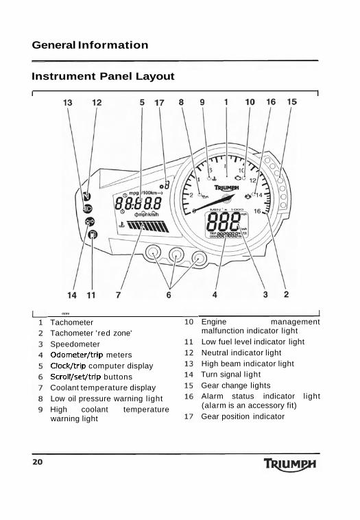
- Tachometer Tachometer 'red zone' Speedometer Odometer/trip meters Clock/trip computer display Scroll/set/trip buttons Coolant temperature display Low oil pressure warning light High coolant temperature warning light
Engine management malfunction indicator light Low fuel level indicator light Neutral indicator light High beam indicator light Turn signal light Gear change lights Alarm status indicator light (alarm is an accessory fit) Gear position indicator
General Information
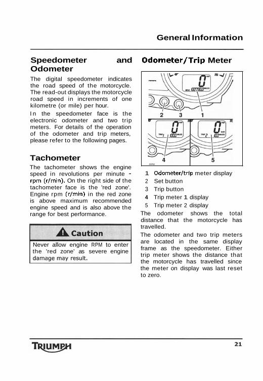
Speedometer and Odometer The digital speedometer indicates the road speed of the motorcycle. The read-out displays the motorcycle road speed in increments of one kilometre (or mile) per hour. I n the speedometer face is the electronic odometer and two trip meters. For details of the operation of the odometer and trip meters, please refer to the following pages.
Tachometer The tachometer shows the engine speed in revolutions per minute - rpm (r/min). On the right side of the tachometer face is the 'red zone'. Engine rpm (r/min) in the red zone is above maximum recommended engine speed and is also above the range for best performance.
Never allow engine RPM to enter the 'red zone' as severe engine
Odometer/Trip Meter
1 Odometer/trip meter display 2 Set button 3 Trip button 4 Trip meter 1 display 5 Trip meter 2 display
The odometer shows the total distance that the motorcycle has travelled. The odometer and two trip meters are located in the same display frame as the speedometer. Either trip meter shows the distance that the motorcycle has travelled since the meter on display was last reset to zero.
General Information
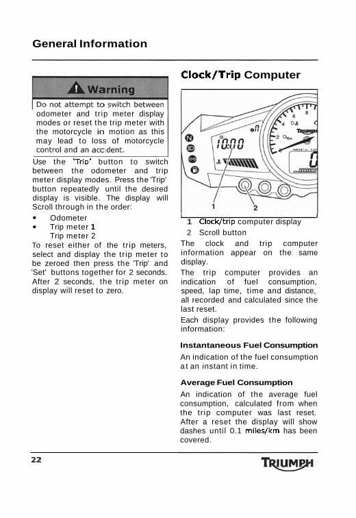
odometer and tr ip meter display modes or reset the trip meter with the motorcycle in motion as this may lead to loss of motorcycle
Use the 'T r i~ ' button to switch between the odometer and trip meter display modes. Press the 'Trip' button repeatedly until the desired display is visible. The display will Scroll through in the order:
Odometer Trip meter 1 Trip meter 2
To reset either of the tr ip meters, select and display the tr ip meter to be zeroed then press the 'Trip' and 'Set' buttons together for 2 seconds. After 2 seconds, the tr ip meter on display will reset to zero.
Clock/Trip Computer
I I 1 Clock/trip computer display 2 Scroll button
The clock and trip computer information appear on the same display. The tr ip computer provides an indication of fuel consumption, speed, lap time, t ime and distance, all recorded and calculated since the last reset. Each display provides the following information:
Instantaneous Fuel Consumption
An indication of the fuel consumption a t an instant in time.
Average Fuel Consumption
An indication of the average fuel consumption, calculated from when the tr ip computer was last reset. After a reset the display will show dashes until 0.1 miles/km has been covered.
Genera I Information
Journey Distance
The total distance travelled, since the last reset.
Journey Time
The total time elapsed, since the last reset.
Average Speed
The average speed is calculated from when the tr ip computer was last reset. After a reset the display will show dashes until 1 mile/km has been covered.
Maximum Speed
The maximum speed achieved since the last reset is displayed.
Lap Timer
Provides information on lap time, maximum speed, average speed, and distance travelled for up to 99 laps.
Trip Computer Operation
Display Section
When the ignition is switched on the clock display is shown. To access the trip computer information press the 'Scroll' button. Press the 'Scroll' button repeatedly until the desired display is visible. The tr ip display will scroll through in the order:
Clock Lap Timer Average Speed
Maximum Speed Journey Distance Journey Time Average Fuel Consumption Instantaneous Fuel Consumption.
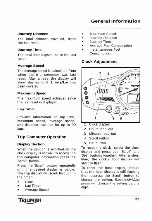
Clock Adjustment
I I 1 Clock display 2 Hours read-out 3 Minutes read-out 4 Scroll button 5 Set button
To reset the clock, select the clock display and press both 'Scroll' and 'Set' buttons together. After a short time, the clock's hour display will start to flash. To reset the hour display, ensure that the hour display is still flashing then depress the 'Scroll' button to change the setting. Each individual press will change the setting by one digit.
General Information
When the correct hour display is shown, press the 'Set' button. The minutes display will begin t o flash. The minutes display is adjusted in the same way as for the hours. Once both hours and minutes are correctly set, press the 'Set' button to confirm the setting. The display will cease to flash.
Trip Computer Reset
I I
1 Trip computer display 2 Scroll button 3 Set button
To reset the tr ip computer only, select one o f the tr ip computer displays, press the 'Scroll' and 'Set' buttons simultaneously for 2 seconds. After 2 seconds, the tr ip computer, not the clock, will reset.
Lap Timer I
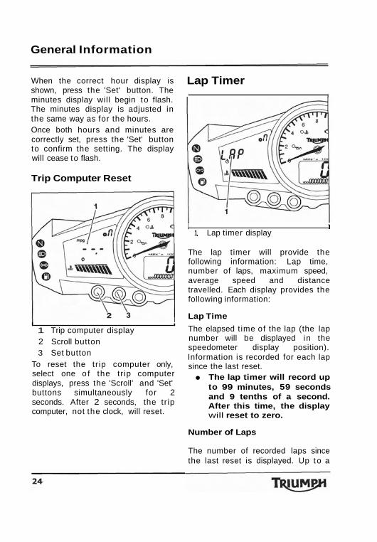
I 1 1 Lap timer display
The lap timer will provide the following information: Lap time, number of laps, maximum speed, average speed and distance travelled. Each display provides the following information:
Lap Time
The elapsed t ime of the lap (the lap number will be displayed in the speedometer display position). Information is recorded for each lap since the last reset.
The lap timer will record up to 99 minutes, 59 seconds and 9 tenths of a second. After this time, the display will reset to zero.
Number of Laps
The number of recorded laps since the last reset is displayed. Up to a
General Information
maximum of 99 laps can be stored by the lap timer.
Maximum Speed
The maximum speed achieved per lap (the lap number will be displayed in the speedometer display position) or the maximum speed achieved during all recorded laps.
Average Speed
The average speed per lap (the lap number will be displayed in the speedometer display position) or the average speed during all recorded laps.
Distance Travelled
The distance travelled per lap (the lap number will be displayed in the speedometer display position) or the distance travelled for all recorded laps.
The lap timer has two modes; Data Recording Mode and Data Retrieval Mode.
Data Recording Mode
I I
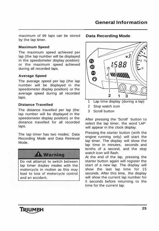
1 Lap time display (during a lap) 2 Stop watch icon 3 Scroll button
After pressing the 'Scroll' button to select the lap timer, the word 'LAP' will appear in the clock display.
Pressing the starter button (with the engine running only) will start the lap timer. The display will show the lap time in minutes, seconds and tenths of a second, and the stop watch icon will flash. At the end of the lap, pressing the starter button again will register the start of a new lap. The display will show the last lap time for 15 seconds. After this time, the display will show the current lap number for 5 seconds before returning to the time for the current lap.
General Information
New lap recording Data Retrieval Mode
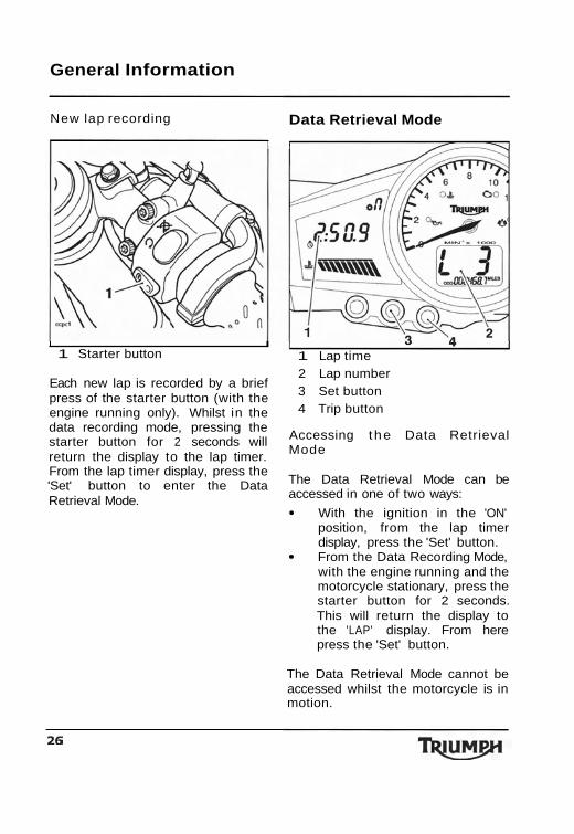
I I 1 Starter button
Each new lap is recorded by a brief press of the starter button (with the engine running only). Whilst in the data recording mode, pressing the starter button for 2 seconds will return the display to the lap timer. From the lap timer display, press the 'Set' button to enter the Data Retrieval Mode.
1 Lap time 2 Lap number 3 Set button 4 Trip button
Accessing t he Data Retrieval Mode
The Data Retrieval Mode can be accessed in one of two ways:
With the ignition in the 'ON' position, from the lap timer display, press the 'Set' button. From the Data Recording Mode, with the engine running and the motorcycle stationary, press the starter button for 2 seconds. This will return the display to the 'LAP' display. From here press the 'Set' button.
The Data Retrieval Mode cannot be accessed whilst the motorcycle is in motion.
General Information
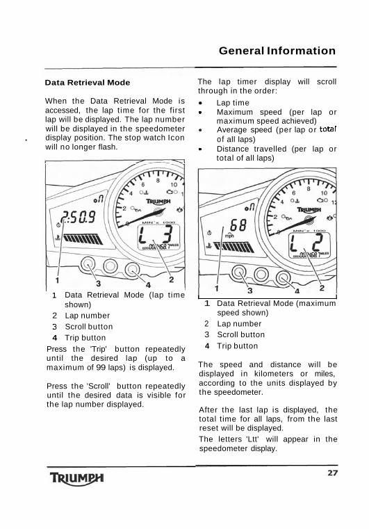
Data Retrieval Mode
When the Data Retrieval Mode is accessed, the lap t ime for the first lap will be displayed. The lap number will be displayed in the speedometer
. display position. The stop watch Icon will no longer flash.
I 1 Data Retrieval Mode (lap t ime shown)
2 Lap number 3 Scroll button 4 Trip button
Press the 'Trip' button repeatedly until the desired lap (up to a maximum of 99 laps) is displayed.
Press the 'Scroll' button repeatedly until the desired data is visible for the lap number displayed.
The lap timer display will scroll through in the order:
Lap time a Maximum speed (per lap or
maximum speed achieved) a Average speed (per lap or total
o f all laps) a Distance travelled (per lap or
total of all laps)
I I 1 Data Retrieval Mode (maximum
speed shown) 2 Lap number 3 Scroll button 4 Trip button
The speed and distance will be displayed in kilometers or miles, according to the units displayed by the speedometer.
After the last lap is displayed, the total time for all laps, from the last reset will be displayed. The letters 'Ltt' will appear in the speedometer display.
General Information
pressing the 'Scroll' button Gear Change Lights repeatedly will display the following:
Total t ime for all laps Maximum speed achieved Average speed of all laps Total distance travelled
I 1 Data Retrieval Mode - total time
display 2 Lap timer 'total time' indication 3 'Scroll' button
Lap Timer Reset
To reset the lap timer, press the 'Scroll' and 'Set' buttons simultaneously for 2 seconds. After 2 seconds, the lap t imer will reset. This will delete the stored data for all stored laps. To exit the Data Retrieval Mode, press the 'Set' button.
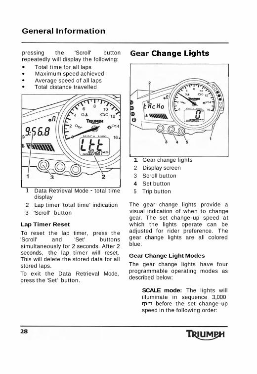
I 1 Gear change lights 2 Display screen 3 Scroll button 4 Set button 5 Trip button
The gear change lights provide a visual indication of when to change gear. The set change-up speed a t which the lights operate can be adjusted for rider preference. The gear change lights are all colored blue.
Gear Change Light Modes
The gear change lights have four programmable operating modes as described below:
SCALE mode: The lights will illuminate in sequence 3,000 rpm before the set change-up speed in the following order:
Suspension
detected,
1 s t LED
2nd LED
3rd LED
4th
5th 6th and 7th LEDs
Gear change lights
LED mode: All seven lights screen (3 LED mode
remain
set Trip button
Maintenance and Adjustment General Information
Front The suspension movement will be affected by adjustment
Front Fork Inspection settings.
Examine each fork for any sign of damage, scratching of the slider surface, or for oil leaks.
Riding the motorcycle witI f any damage or leakage is found defective or damaged suspensio consult an authorized Triumph dealer. To check that the forks operate smoothly:
Position the motorcycle on level ground. While holding the handlebars and applying the front brake, pump the forks up and down several times.
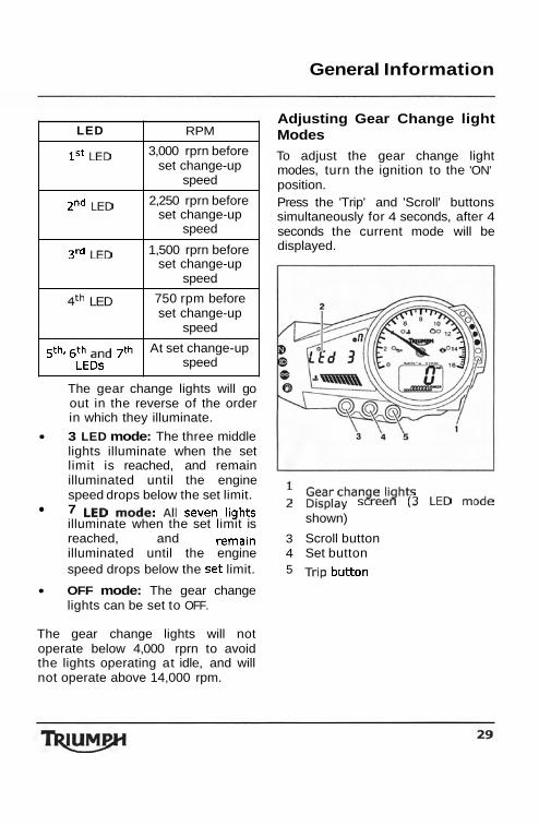
LED RPM
3,000 rprn before set change-up
speed
2,250 rprn before set change-up
speed
1,500 rprn before set change-up
speed
LED 750 rpm before set change-up
speed
At set change-up speed
I f roughness or excessive The gear change lights will go stiffness is consult out in the reverse of the order your authorized Triumph dealer. in which they illuminate.
3 LED mode: The three middle lights illuminate when the set limit is reached, and remain illuminated until the engine speed drops below the set limit. 7 illuminate when the set limit is reached, and illuminated until the engine speed drops below the limit.
OFF mode: The gear change lights can be set to OFF.
The gear change lights will not operate below 4,000 rprn to avoid the lights operating at idle, and will not operate above 14,000 rpm.
Adjusting Gear Change light Modes
To adjust the gear change light modes, turn the ignition to the 'ON' position. Press the 'Trip' and 'Scroll' buttons simultaneously for 4 seconds, after 4 seconds the current mode will be displayed.
shown)
3 Scroll button 4 Set button 5
General Information
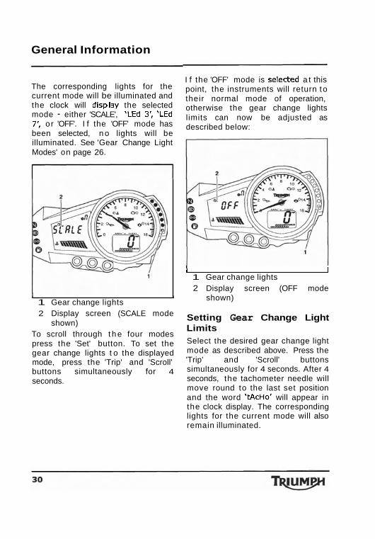
The corresponding lights for the current mode will be illuminated and the clock will display the selected mode - either 'SCALE', 'LEd 3: 'LEd 7: o r 'OFF'. I f the 'OFF' mode has been selected, n o lights will be illuminated. See 'Gear Change Light Modes' on page 26.
I f the 'OFF' mode is selected a t this point, the instruments will return to their normal mode of operation, otherwise the gear change lights limits can now be adjusted as described below:
I I
1 Gear change lights 2 Display screen (SCALE mode
shown) To scroll through t h e four modes press the 'Set' button. To set the gear change lights t o the displayed mode, press the 'Trip' and 'Scroll' buttons simultaneously for 4 seconds.
I I 1 Gear change lights 2 Display screen (OFF mode
shown)
Setting Gear Change Light Limits Select the desired gear change light mode as described above. Press the 'Trip' and 'Scroll' buttons simultaneously for 4 seconds. After 4 seconds, the tachometer needle will move round to the last set position and the word 'tAcHo' will appear in the clock display. The corresponding lights for the current mode will also remain illuminated.
Maintenance and Adjustment
Steering/Wheel Bearings
I
I
To prevent risk of injury from the motorcycle falling during the inspection, ensure that the motorcycle is stabilised and secured on a suitable support. Do not exert extreme force against each wheel or rock each wheel vigorously as this may cause the motorcycle to become unstable and cause injury by falling from its support. Ensure that the position of the support block will not cause damage to the sump.
Steering Inspection Lubricate and inspect the condition of the steering (headstock) bearings in accordance with scheduled maintenance requirements.
NOTE Always inspect the wheel bearings at the same time as the steering bearings.
Inspecting the Steering (headstock) Bearings for Free-Play
I I Inspecting the steering for free-play Position the motorcycle on level ground, in an upright position. Raise the front wheel above the ground and support the motorcycle. Standing at the front of the motorcycle, hold the lower end of the front forks and try to move them forward and backward. I f any free-play can be detected in the steering (headstock) bearings, ask your authorized Triumph dealer to inspect and rectify any faults before riding.
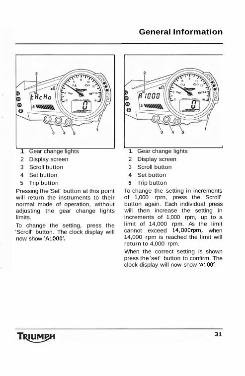
L I 1 Gear change lights 2 Display screen 3 Scroll button 4 Set button 5 Trip button
Pressing the 'Set' button at this point will return the instruments to their normal mode of operation, without adjusting the gear change lights limits. To change the setting, press the 'Scroll' button. The clock display will now show 'A1000'.
General Information
I I 1 Gear change lights 2 Display screen 3 Scroll button 4 Set button 5 Trip button
To change the setting in increments of 1,000 rprn, press the 'Scroll' button again. Each individual press will then increase the setting in increments of 1,000 rpm, up to a limit of 14,000 rpm. As the limit cannot exceed 14,00Orpm, when 14,000 rpm is reached the limit will return to 4,000 rpm. When the correct setting is shown press the 'set' button to confirm. The clock display will now show 'A100'.
General Information
I I
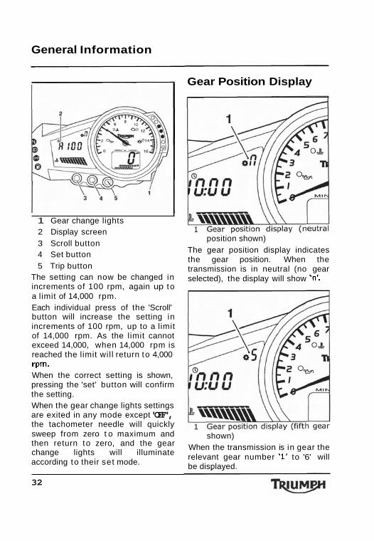
1 Gear change lights 2 Display screen 3 Scroll button 4 Set button 5 Trip button
The setting can now be changed in increments of 100 rpm, again up to a limit of 14,000 rpm. Each individual press of the 'Scroll' button will increase the setting in increments of 100 rpm, up to a limit of 14,000 rpm. As the limit cannot exceed 14,000, when 14,000 rpm is reached the limit wil l return to 4,000 rpm. When the correct setting is shown, pressing the 'set' button will confirm the setting. When the gear change lights settings are exited in any mode except 'OFF', the tachometer needle will quickly sweep from zero t o maximum and then return to zero, and the gear change lights will illuminate according to their set mode.
32
Gear Position Display
position shown) The gear position display indicates the gear position. When the transmission is in neutral (no gear selected), the display will show 'n:
shown) When the transmission is in gear the relevant gear number '1' to '6' will be displayed.
General Information
Coolant Temperature Gauge
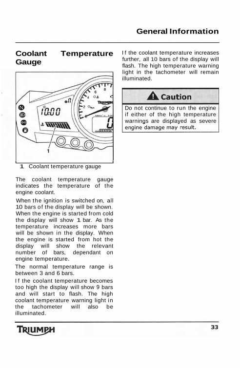
I I 1 Coolant temperature gauge
The coolant temperature gauge indicates the temperature of the engine coolant.
When the ignition is switched on, all 10 bars o f the display will be shown. When the engine is started from cold the display will show 1 bar. As the temperature increases more bars will be shown in the display. When the engine is started from hot the display will show the relevant number of bars, dependant on engine temperature. The normal temperature range is between 3 and 6 bars. I f the coolant temperature becomes too high the display will show 9 bars and will start to flash. The high coolant temperature warning light in the tachometer will also be illuminated.
I f the coolant temperature increases further, all 10 bars of the display will flash. The high temperature warning light in the tachometer will remain illuminated.
Do not continue to run the engine if either of the high temperature warnings are displayed as severe
General Information
Warning Lights
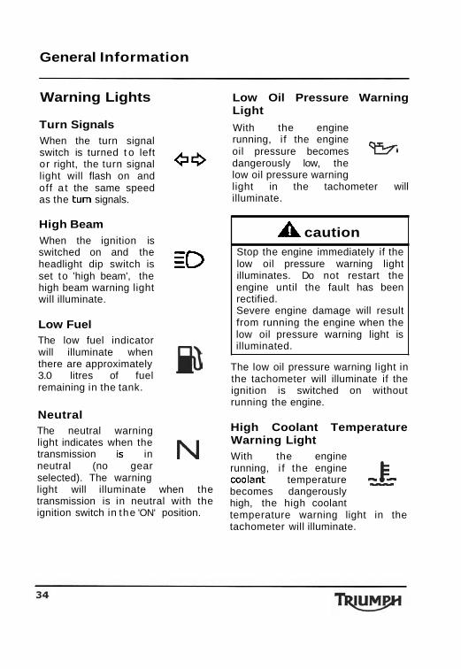
Turn Signals When the turn signal switch is turned t o left or right, the turn signal light will flash on and
4C3 off a t the same speed as the turn signals.
High Beam When the ignition is switched on and the headlight dip switch is = set to 'high beam', the
=o high beam warning light will illuminate.
Low Fuel The low fuel indicator will illuminate when there are approximately 3.0 litres of fuel remaining in the tank.
Neutral The neutral warning light indicates when the transmission is in N neutral (no gear selected). The warning light will illuminate when the transmission is in neutral with the ignition switch in the 'ON' position.
Low Oil Pressure Warning Light
With the engine running, i f the engine oil pressure becomes 9 9 4
dangerously low, the low oil pressure warning light in the tachometer will illuminate.
A caution Stop the engine immediately if the low oil pressure warning light illuminates. Do not restart the engine until the fault has been rectified. Severe engine damage will result from running the engine when the low oil pressure warning light is illuminated.
The low oil pressure warning light in the tachometer will illuminate if the ignition is switched on without running the engine.
High Coolant Temperature Warning Light With the engine running, i f the engine coolant temperature becomes dangerously high, the high coolant temperature warning light in the tachometer will illuminate.
General Information
A Caution Stop the engine immediately if the high coolant temperature warning light illuminates. Do not restart the engine until the fault has been rectified. Severe engine damage will result from running the engine when the high coolant temperature warning light is illuminated.
The high coolant temperature warning light in the tachometer will illuminate if the ignition is switched on without running the engine.
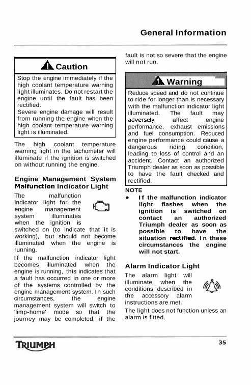
Engine Management System Malfunction Indicator Light The malfunction indicator light for the engine management system illuminates when the ignition is switched on (to indicate that i t is working), but should not become illuminated when the engine is running. I f the malfunction indicator light becomes illuminated when the engine is running, this indicates that a fault has occurred in one or more of the systems controlled by the engine management system. In such circumstances, the engine management system will switch to 'limp-home' mode so that the journey may be completed, if the
fault is not so severe that the engine will not run.
I))r Warning Reduce speed and do not continue to ride for longer than is necessary with the malfunction indicator light illuminated. The fault may adverse1 y affect engine performance, exhaust emissions and fuel consumption. Reduced engine performance could cause a dangerous riding condition, leading to loss of control and an accident. Contact an authorized Triumph dealer as soon as possible to have the fault checked and rectified.
I I
NOTE I f the malfunction indicator light flashes when the ignition is switched on contact an authorized Triumph dealer as soon as possible to have the situation rectified. I n these circumstances the engine will not start.
Alarm Indicator Light The alarm light will illuminate when the conditions described in the accessory alarm instructions are met. The light does not function unless an alarm is fitted.
General Information
Ignition Key
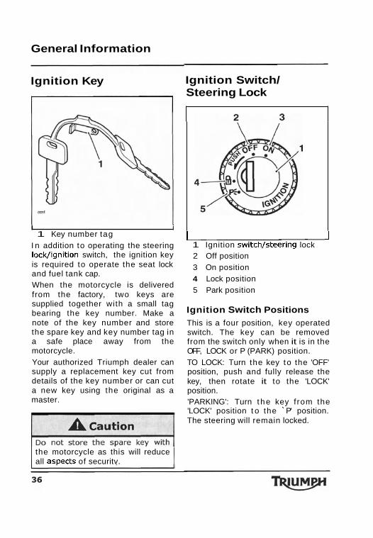
I I 1 Key number tag
I n addition to operating the steering lock/ignition switch, the ignition key is required to operate the seat lock and fuel tank cap. When the motorcycle is delivered from the factory, two keys are supplied together with a small tag bearing the key number. Make a note of the key number and store the spare key and key number tag in a safe place away from the motorcycle. Your authorized Triumph dealer can supply a replacement key cut from details of the key number or can cut a new key using the original as a master.
the motorcycle as this will reduce all asDects of securitv.
Ignition Switch/ Steering Lock
c 1 Ignition switch/steering lock 2 Off position 3 On position 4 Lock position 5 Park position
Ignition Switch Positions This is a four position, key operated switch. The key can be removed from the switch only when it is in the OFF, LOCK or P (PARK) position. TO LOCK: Turn the key to the 'OFF' position, push and fully release the key, then rotate it to the 'LOCK' position. 'PARKING': Turn the key f rom the 'LOCK' position t o the ' P' position. The steering will remain locked.
General Information
NOTE Brake Lever Adjuster Do not leave the steering lock in the 'P' position for long periods of time as this will cause the battery to discharge.
ny unauthorized use of the
s and may also cause
n tne Key In tne 'LULK' o 'tion the steering will bec
er turn the key to the 'LOCK' or positions while the motorcycle
s moving as this will cause the teering to lock. Locked steering ill cause loss of motorcycle
, Warn . . ,
ing .,
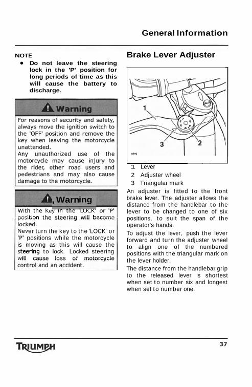
I 1 Lever 2 Adjuster wheel 3 Triangular mark
An adjuster is fitted to the front brake lever. The adjuster allows the distance from the handlebar t o the lever to be changed to one of six positions, t o suit the span of the operator's hands. To adjust the lever, push the lever forward and turn the adjuster wheel to align one of the numbered positions with the triangular mark on the lever holder. The distance from the handlebar grip to the released lever is shortest when set t o number six and longest when set t o number one.
General Information
b & w Do not attempt to adjust the lever with the motorcycle ~n motion as this may lead to loss of motorcycle control and an accident. After adjusting the lever, operate the motorcycle in an area free from traffic to gain familiarity with the new lever setting. Do not loan your motorcycle t o anyone as they may change the lever setting from the one you are familiar with causing loss of control o r an accident.
Right Handlebar Switches
I I
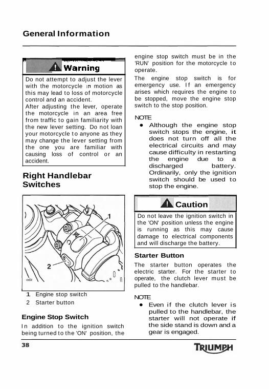
1 Engine stop switch 2 Starter button
Engine Stop Switch I n addition to the ignition switch being turned to the 'ON' position, the
engine stop switch must be in the 'RUN' position for the motorcycle t o operate. The engine stop switch is for emergency use. I f an emergency arises which requires the engine t o be stopped, move the engine stop switch to the stop position.
NOTE Although the engine stop switch stops the engine, it does not turn off all the electrical circuits and may cause difficulty in restarting the engine due to a discharged battery. Ordinarily, only the ignition switch should be used to stop the engine.
A Caution Do not leave the ignition switch in the 'ON' position unless the engine is running as this may cause damage to electrical components and will discharge the battery.
Starter Button The starter button operates the electric starter. For the starter to operate, the clutch lever must be pulled to the handlebar.
NOTE Even i f the clutch lever is pulled to the handlebar, the starter will not operate if the side stand is down and a gear is engaged.
General Information
With the engine running, the starter button functions as the lap timer 'trigger' button. Momentarily pressing the starter button will start the lap timer recording the next lap.
Left Handlebar Switches
I I
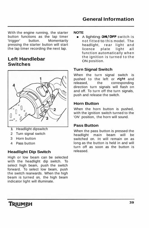
1 Headlight dipswitch 2 Turn signal switch 3 Horn button 4 Pass button
Headlight Dip Switch High or low beam can be selected with the headlight dip switch. To select high beam, push the switch forward. To select low beam, push the switch rearwards. When the high beam is turned on, the high beam indicator light will illuminate.
NOTE A lighting ON/OFF swi tch i s n o t f i t t e d to t h i s model. The headlight, r e a r l i gh t a n d l icence p la te l i gh t a l l func t ion automat ical ly w h e n t h e ign i t ion i s t u rned t o t h e ON posit ion.
Turn Signal Switch When the turn signal switch is pushed to the left or right and released, the corresponding direction turn signals will flash on and off. To turn off the turn signals, push and release the switch.
Horn Button When the horn button is pushed, with the ignition switch turned to the 'ON' position, the horn will sound.
Pass Button When the pass button is pressed the headlight main beam will be switched on. I t will remain on as long as the button is held in and will turn off as soon as the button is released.
General Information
Fuel Requirement/ Refuelling
Fuel Grade
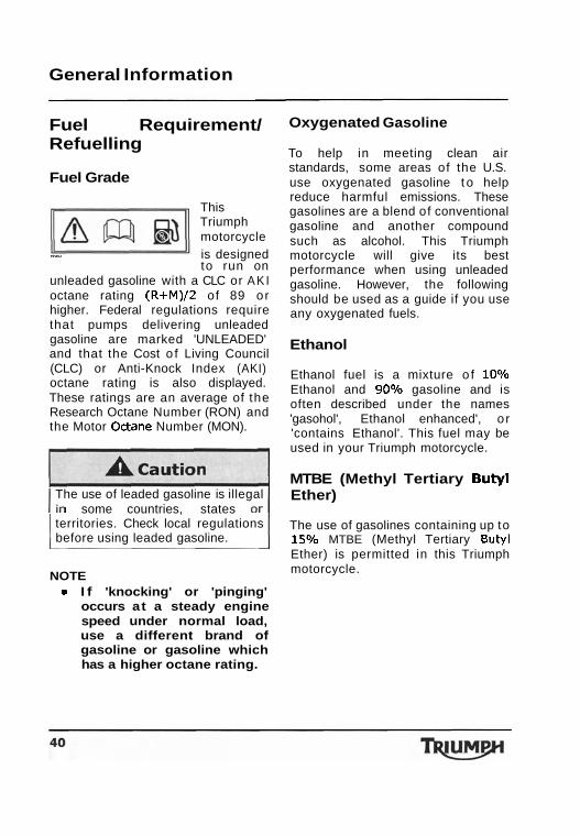
This Triumph motorcycle
- is designed to run on
unleaded gasoline with a CLC or A K I octane rating (R+M)/2 of 89 or higher. Federal regulations require that pumps delivering unleaded gasoline are marked 'UNLEADED' and that the Cost o f Living Council (CLC) or Anti-Knock Index (AKI) octane rating is also displayed. These ratings are an average of the Research Octane Number (RON) and the Motor Octane Number (MON).
The use of leaded gasoline is illegal some countries, states
territories. Check local regulations before using leaded gasoline.
NOTE I f 'knocking' or 'pinging' occurs at a steady engine speed under normal load, use a different brand of gasoline or gasoline which has a higher octane rating.
Oxygenated Gasoline
To help in meeting clean air standards, some areas of the U.S. use oxygenated gasoline t o help reduce harmful emissions. These gasolines are a blend of conventional gasoline and another compound such as alcohol. This Triumph motorcycle will give its best performance when using unleaded gasoline. However, the following should be used as a guide if you use any oxygenated fuels.
Ethanol
Ethanol fuel is a mixture o f 10% Ethanol and 90% gasoline and is often described under the names 'gasohol', Ethanol enhanced', o r 'contains Ethanol'. This fuel may be used in your Triumph motorcycle.
MTBE (Methyl Tertiary Butyl Ether)
The use of gasolines containing up to 15% MTBE (Methyl Tertiary Butyl Ether) is permitted in this Triumph motorcycle.
General Information
Methanol
A Caution Fuels containing methanol should not be used as damage to components in the fuel system can be caused by contact with methanol.
L cautic Because of the generally higher volatility of oxygenated fuels, starting, engine response and fuel consumption may be adversely affected by their use. Should any of these difficulties be experienced, run the motorcycle on normal unleaded gasoline.
To help reduce hazards associated with refuelling, always observe the following fuel safety instructions: Gasoline (fuel) is highly flammable and can be explosive under certain conditions. When refuelling, turn the ignition switch to the 'OFF'
Do not smoke. Do not use a mobile telephone. Make sure the refuelling area is well ventilated and free from any source of flame or sparks. This includes any appliance with a pilot
Never fill the tank until the fuel level rises into the filler neck. Heat from sunlight or other sources may cause the fuel to expand and overflow creating a fire hazard. After refuelling always check that the fuel filler cap is correctly closed and locked. Because gasoline (fuel) is highly flammable, any fuel leak or spillage, or any failure t o observe
General Information
Fuel Tank Cap Filling the Fuel Tank Avoid filling the tank in rainy or dusty conditions where airborne material can contaminate the fuel.
cbmml
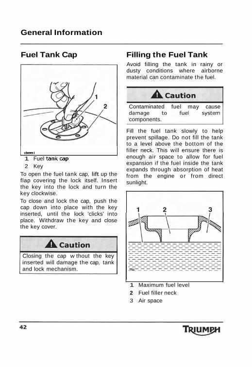
1 Fuel tankcap 2 Key
To open the fuel tank cap, lift up the flap covering the lock itself. Insert the key into the lock and turn the key clockwise. To close and lock the cap, push the cap down into place with the key inserted, until the lock 'clicks' into place. Withdraw the key and close the key cover.
Closing the cap w thout the key inserted will damage the cap, tank and lock mechanism.
Contaminated fuel may cause
components.
Fill the fuel tank slowly to help prevent spillage. Do not fill the tank to a level above the bottom of the filler neck. This will ensure there is enough air space to allow for fuel expansion if the fuel inside the tank expands through absorption of heat from the engine o r from direct sunlight.
I I 1 Maximum fuel level 2 Fuel filler neck 3 Air space
General Information
up the spillage immediately an dispose of the materials use
Take care not to spill any fuel the engine, exhaust pipes, tires any other part of the motorcycle. Because fuel is highly flammabl any fuel leak or spillage, or an failure to observe the safety advic given above may lead to a fir hazard, which could cause damag to property and injury or death t
Fuel spilled near to, or onto th tires will reduce the tire's ability t grip the road. This will give rise t a dangerous riding conditio
After refuelling always check that the fuel filler cap is correctly closed and locked.
Tool Kit and Handbook
Stand
Side Stand
mrng
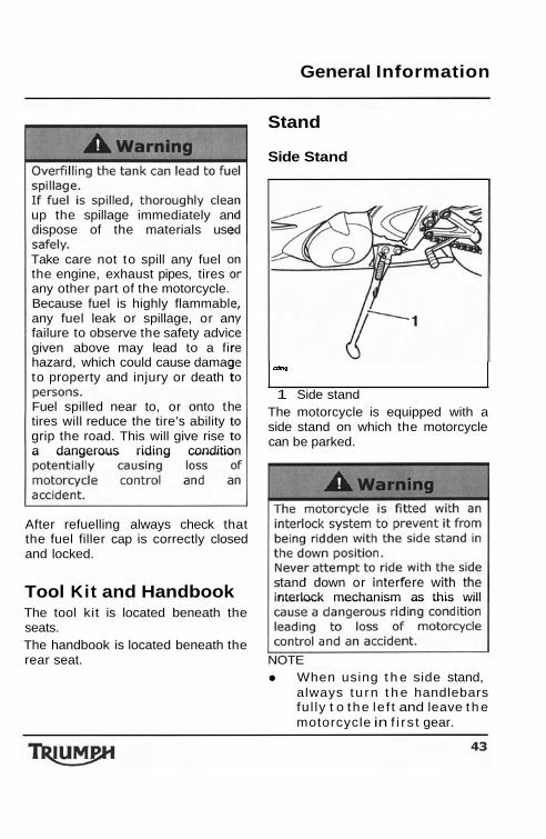
1 Side stand The motorcycle is equipped with a side stand on which the motorcycle can be parked.
tand down or interfere with the nterlock mechanism as this will
The tool kit is located beneath the seats. The handbook is located beneath the rear seat. NOTE
When using t h e side stand, always tu rn t h e handlebars ful ly t o the le f t and leave t he motorcycle in f i r s t gear.
General Information
Whenever the side stand is used, down at the rear to engage in the before riding, always ensure that the seat lock. stand is fully up after first sitting on the motorcycle. For instructions on safe parking, refer to the 'How to Ride the Motorcycle' section.
Seat Lock
Rider's Seat
riding, after fitting a
seat could cause loss of motorcyc control and an accident.
I / I Rear Seat/Seat Cover
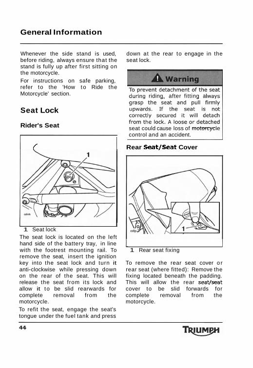
1 Seat lock The seat lock is located on the left hand side of the battery tray, in line 1 1 with the footrest mounting rail. To 1 Rear seat fixing remove the seat, insert the ignition key into the seat lock and turn it To remove the rear seat cover o r anti-clockwise while pressing down rear seat (where fitted): Remove the on the rear of the seat. This will fixing located beneath the padding. release the seat from its lock and This will allow the rear seat/seat allow it t o be slid rearwards for cover to be slid forwards for complete removal from the complete removal from the motorcycle. motorcycle. To refit the seat, engage the seat's tongue under the fuel tank and press
General Information
Brea ki ng-In
pF?q R.P.M.
Breaking-in is the name given to the process that occurs
during the first hours of a new vehicle's operation. I n particular, internal friction in the engine will be higher when components are new. Later on, when continued operation of the engine has ensured that the components have 'bedded in', this internal friction will be greatly reduced.
Both during and after breaking in has been completed: Do not over-rev the engine when cold. Do not let the engine labour. Always downshift before the engine begins to 'struggle'. Do not ride with engine speeds unnecessarily high. Changing up a gear helps reduce fuel consumption, reduces noise and helps to protect the environment.
A period of careful breaking in will ensure lower exhaust emissions, and will optimise performance, fuel economy and longevity of the engine and other motorcycle components. During the first 500 miles (800 kilometres):
Do not use full throttle. Avoid high engine speeds at all times. Avoid riding at one constant engine speed, whether fast or slow, for a long period of time. Avoid aggressive starts, stops, and rapid accelerations, except in an emergency. Do not ride at speeds greater than 314 of maximum engine speed.
From 500 to 1000 miles (800 to 1500 kilometres) :
Engine speed can gradually be increased to the rev limit for short periods.
General Information
Safe Operation
Daily Safety Checks Check the following items each day before you ride. The time
required is minimal, and these checks will help ensure a safe, reliable ride. I f any irregularities are found during these checks, refer to the Maintenance and Adjustment section or see your authorized Triumph dealer for the action required to return the motorcycle t o a safe operating condition.
Check:
Fuel: Adequate supply in tank, no fuel leaks (page 40). Engine oil: Correct level on dipstick. Add correct specification oil as required. No leaks from the engine or oil cooler (page 68). Drive chain: Correct adjustment (page 78). Tires/Wheels: Correct inflation pressures (when cold). Tread depth/ wear, tirelwheel damage, punctures etc. (page 92). Nuts, bolts, fasteners: Visually check that steering and suspension components, axles, and all controls are properly tightened or fastened. Inspect all areas for loose/damaged fixings. Steering Action: Smooth but not loose from lock to lock. No binding of any of the control cables (page 86). Brakes: Pull the brake lever and push the brake pedal t o check for correct resistance. Investigate any leverlpedal where the travel is excessive before meeting resistance, or if either control feels spongy in operation (page 82). Brake pads: There should be more than 0.05 in (1.5 mm) of friction material remaining on all the pads (page 82). Brake Fluid Levels: No brake fluid leakage. Brake fluid levels must be between the 'MAX' and 'MIN' marks on both reservoirs (page 84). Front Forks: Smooth action. No leaks from fork seals (page 88).
General Information
Throttle: Throttle grip free-play 0.08-0.12 in (2-3mm). Ensure that the throttle grip returns to the idle position without sticking (page 74). Clutch: Smooth operation and correct cable free-play (page 77). Coolant: No coolant leakage. Check the coolant level in the expansion tank (when the engine is cold) (page 72).
Electrical equipment: All lights and the horn function correctly (page 36). Engine stop: Stop switch turns the engine off (page 50). Stands: Returns to the fully up position by spring tension. Return springs not weak or damaged (page 43).
General Information
This page intentionally left blank
How to Ride the Motorcycle
HOW TO RIDE THE MOTORCYCLE
Table of Contents To Stop the Engine ........................................................................ 50 To Start the Engine ....................................................................... 50 Moving Off ................................................................................... 5 1 Changing Gears ............................................................................ 52 Braking ....................................................................................... 52 Parking ........................................................................................ 55 Considerations for High Speed Operation ......................................... 56
How to Ride the Motorcycle
To Stop the Engine
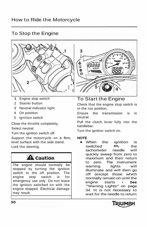
I 1 Engine stop switch 2 Starter button 3 Neutral indicator light 4 On position 5 Ignition switch
Close the throttle completely. Select neutral. Turn the ignition switch off.
I
To Start the Engine Check that the engine stop switch is in the run position. Ensure the transmission is in neutral. Pull the clutch lever fully into the handlebar. Turn the ignition switch on.
Support the motorcycle on a firm, NOTE level surface with the side stand. When the ignition is Lock the steering. switched 0% the
tachometer needle will
A caution The engine should normally be stopped by turning the ignition switch to the off position. The engine stop switch is for emergency use only. Do not leave the ignition switched on with the engine stopped. Electrical damage may result.
quickly sweep from zero to maximum and then return to zero. The instrument warning lights will illuminate and will then go off (except those which normally remain on until the engine starts - See "Warning Lights" on page 34. It is not necessary to wait for the needle to return
How to Ride the Motorcycle
to zero before starting the engine. I n very cold conditions, part open the throttle to aid cold starting. Return it to the closed position once the engine has started.
death w i th~n a short per~od of
Cautia - Do not operate the starter continuously for more than 5 seconds as the starter motor will overheat and the battery will become discharged. Wait 15 seconds between each operation of the starter to allow for cooling and recovery of battery power. Do not let the engine idle for long periods as this may lead to overheating which will cause damage to the engine.
A caution The low oi l pressure warning light should go out shortly after the engine starts. I f the low oil pressure warning light stays on after starting the engine, stop the engine immediately and investigate the cause. Running the engine with low oil pressure will cause severe engine damage.
The motorcycle is equipped with starter lockout switches. The switches prevent the electric starter from operating when the transmission is not in neutral with the sidestand down. I f the sidestand is extended whilst the engine is running, and the transmission is not in neutral then the engine will stop irrespective of clutch position.
Moving Off Pull in the clutch lever and select first gear. Open the throttle a little and let out the clutch lever slowly. As the clutch starts to engage, open the throttle a little more, allowing enough engine speed to avoid stalling.
How to Ride the Motorcycle
Changing Gears
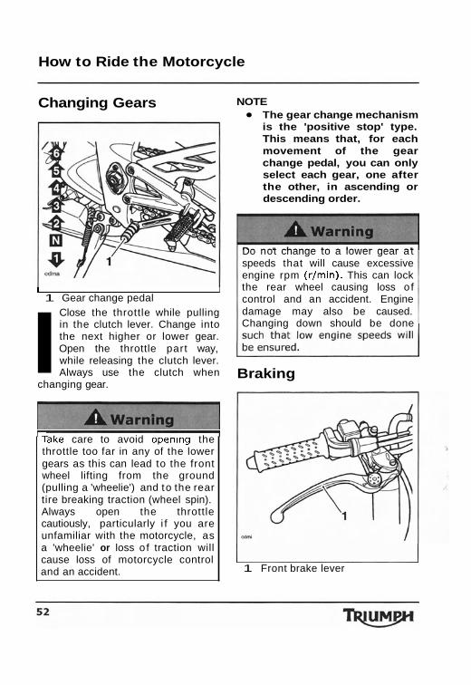
I I 1 Gear change pedal
I Close the throttle while pulling in the clutch lever. Change into the next higher or lower gear. Open the throttle part way, while releasing the clutch lever. Always use the clutch when
changing gear.
- TaKe care to avoid openlng the throttle too far in any of the lower gears as this can lead to the front wheel lifting from the ground (pulling a 'wheelie') and to the rear tire breaking traction (wheel spin). Always open the throttle cautiously, particularly i f you are unfamiliar with the motorcycle, as a 'wheelie' or loss o f traction will cause loss of motorcycle control and an accident.
NOTE The gear change mechanism is the 'positive stop' type. This means that, for each movement of the gear change pedal, you can only select each gear, one after the other, in ascending or descending order.
Do not change to a lower gear a t speeds that will cause excessive engine rpm (rlmin). This can lock the rear wheel causing loss o f control and an accident. Engine damage may also be caused. Changing down should be done
Braking
I 1 Front brake lever
How to Ride the Motorcycle
I - A warning I -
WHEN BRAKING, OBSERVE THE FOLLOWING:
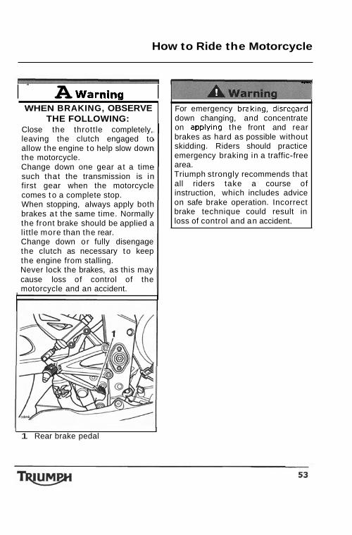
Close the throttle completely, leaving the clutch engaged to allow the engine to help slow down the motorcycle. Change down one gear a t a time such that the transmission is in first gear when the motorcycle comes t o a complete stop. When stopping, always apply both brakes a t the same time. Normally the front brake should be applied a little more than the rear. Change down or fully disengage the clutch as necessary to keep the engine from stalling. Never lock the brakes, as this may cause loss of control of the motorcycle and an accident.
I I 1 Rear brake pedal
C~ - ,
For emergency braklng, d~sregard down changing, and concentrate on applylng the front and rear brakes as hard as possible without skidding. Riders should practice emergency braking in a traffic-free area. Triumph strongly recommends that all riders take a course of instruction, which includes advice on safe brake operation. Incorrect brake technique could result in loss of control and an accident.
I
How to Ride the Motorcycle
ontrol and an accident. ndependent use of the front or
brakes reduces overall ing performance. Extreme ing may cause either wheel to
riding in wet or rainy
ill be reduced. All of your actions
intermittently. Continuous brake application can overheat the brakes and reduce their effectiveness. Riding with your foot on the brake pedal or your hands on the brake lever may actuate the brake light, giving a false indication to other road users. It may also overheat the brake, reducing braking effectiveness. Do not coast with the engine switched off, and do not tow the motorcycle. The transmission is pressure-lubricated only when the engine is running. Inadequate lubrication may cause damage or seizure of the transmission, which can lead t o sudden loss of
cle control and a
How to Ride the Motorcycle
Parking
I
rn
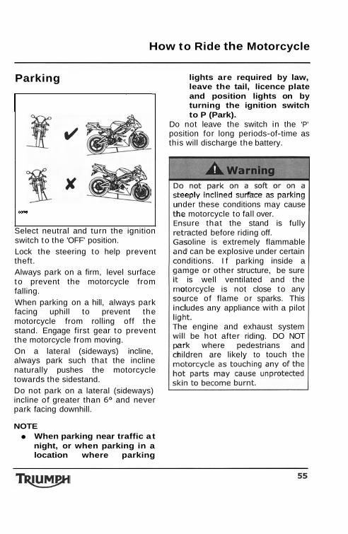
Select neutral and turn the ignition switch to the 'OFF' position. Lock the steering to help prevent theft. Always park on a firm, level surface to prevent the motorcycle from falling. When parking on a hill, always park facing uphill to prevent the motorcycle from rolling off the stand. Engage first gear to prevent the motorcycle from moving. On a lateral (sideways) incline, always park such that the incline naturally pushes the motorcycle towards the sidestand. Do not park on a lateral (sideways) incline of greater than 6 O and never park facing downhill.
NOTE When parking near traffic a t night, or when parking in a location where parking
lights are required by law, leave the tail, licence plate and position lights on by turning the ignition switch to P (Park).
Do not leave the switch in the 'P' position for long periods-of-time as this will discharge the battery.
teeply inclined surface as parking nder these conditions may cause he motorcycle to fall over.
ure that the stand is fully acted before riding off. oline is extremely flammable can be explosive under certain
onditions. I f parking inside a amge or other structure, be sure
is well ventilated and the otorcycle is not close to any
rce of flame or sparks. This udes any appliance with a pilot
engine and exhaust system be hot after riding. DO NOT
ark where pedestrians and hildren are likely to touch the
How to Ride the Motorcycle
Considerations for High Speed Operation
ngerous since the t ime available react to given traffic situations
ideration of weather and
losed-course on-road competition r on closed course racetracks.
-speed operation should only be attempted by riders who
been instructed in the
M Is
I - - -1 ne nandling character~st~cs or a motorcycle a t high speed may vary from those you are familiar with a t legal road speeds. Do not attempt high-speed operation unless you have received sufficient training and have the required skills as a serious accident may result from incorrect operation. -
lIll A srning - I
The [terns llsted are extremely important and must never be neglected. A problem, which may not be noticed at normal operating speeds, may be greatly exaggerated at high speeds.
General Ensure the motorcycle has been maintained according to the scheduled maintenance chart.
Steering Check that the handlebar turns '* smoothly without excessive free play or tight spots. Ensure that the control cables do not restrict the . steering in any way.
Luggage Make certain that any luggage containers are closed, locked and securely fitted to the motorcycle.
How to Ride the Motorcycle
Brakes Check that the front and rear brakes are functioning properly.
Tires
High-speed operation is hard on tires, and tires that are in good condition are crucial to riding safely. Examine their overall condition, inflate t o the correct pressure (when the tires are cold), and check the wheel balance. Securely fit the valve caps after checking tire pressures. Observe the information given in the maintenance and specification sections on tire checking and tire safety.
grade and type of oil is used when topping-up.
Coolant Check that the coolant level is at the upper level line in the expansion tank. (Always check the level with the engine cold).
Electrical Equipment Make certain that the headlight, rearlbrake light, turn signals, horn etc., all work properly.
Miscellaneous Visually check that all fixings are tight.
Fuel Have sufficient fuel for the increased fuel consumption that will result from high-speed operation.
A Caution The exhaust system is fitted with a catalytic converter to help reduce exhaust emission levels. The catalytic converter can be permanently damaged if the motorcycle is allowed to run out of fuel o r if the fuel level is allowed to get very low. Always ensure you have adequate fuel for your journey.
Engine Oil Make certain that the engine oil level is correct. Ensure that the correct
Accessories and Loading
ACCESSORIES AND LOADING The addition of accessories and carriage of additional weight can affect the motorcycle's handling characteristics causing changes in stability and necessitating a reduction in speed. The following information has been prepared as a guide to the potential hazards of adding accessories t o a motorcycle and carrying passengers and additional loads.
Always ensure any loads carried are evenly distributed on both sides of the motorcycle. Ensure hat the load is correctly secured
such that it will not move around hile the motorcycle is in motion.
hough not while the is in motion) and
t the load does not
Never exceed the maximum ehicle loading weight of 430 LB
mum loading weight is from the combined
e rider, passenger, any fitted and any load
I
Do not ~nstal l accessortes or carry luggage that impa~rs the control of the motorcycle. Make sure that you have not adversely affected the visibility of any lighting component, road clearance, banking capability (i.e. lean angle), control operation, wheel travel, front fork movement, visibility in any d~rection, or any other aspect of the motorcycle's operation.
Accessories and Loading
circumstances. Speeds in excess of 80 mph (130 kmlh) should not be attempted on an accessory equipped motorcycle
The presence of accessories will cause changes in the stability and handling of the motorcycle. Failure to allow for changes in motorcycle stability may lead to loss of control or an accident. Remember that the 80mph (130 km/h) absolute limit will be reduced by the fitting of non-
r on closed course racetracks. h-speed operation should only
be attempted by riders who been instructed in the
iques necessary for high riding and are familiar with
e motorcycle's characteristics in
igh-speed operation in any other ircumstances is dangerous and
Accessories and Loading
the operation of the motorcycle. with the changes in motorcycle
passenger footrests and t o firmly s for the hold onto the seat strap or the rider's waist o r hips. The passenger should also be advised to lean with the rider when travelling around corners and not to lean unless the rider does so.
Weight attached to the handlebar or front fork will increase the mass of the steering assembly and can result in loss of steering control leading to an accident.
Accessories and Loading
the footrests provided. A passenger who is not tall enough to reach the footrests will be
must not impair control of the motorcycle, must be securely attached and must not extend beyond the rear or sides of the
Carriage of objects in excess of 11 lb (5 kg) in weight, that are insecure, impair control or extend beyond the rear or sides of the
A caution Do not allow luggage to rest on or against the upper portion of the rear bodywork. Allowing luggage to rest on or against the upper portion of the rear bodywork could close the airgap between the bodywork and the exhaust potentially causing the bodywork to become damaged by overheating.
Accessories and Loading
This page intentionally left blank
Maintenance and Adjustment
MAINTENANCE AND ADJUSTMENT
Table of Contents Scheduled Maintenance ................................................................. 64 Engine Oil .................................................................................... 68 Cooling System ............................................................................ 72 Throttle Control ............................................................................ 74
......................................................................................... Clutch 77 Drive Chain .................................................................................. 78 Brakes ........................................................................................ 82 Windshield Cleaning ...................................................................... 85 Steering/Wheel Bearings ................................................................ 86 Front Suspension .......................................................................... 88 Tires ........................................................................................... 92 Battery ........................................................................................ 96 Fuse Box ..................................................................................... 98 Headlights ................................................................................. 100 Rear Light .................................................................................. 103 Turn Signal Lights ....................................................................... 103 Licence Plate Light ...................................................................... 103 Cleaning ............................................................................. 104
Maintenance and Adjustment
Scheduled Maintenance Warranty and other service information, including the service
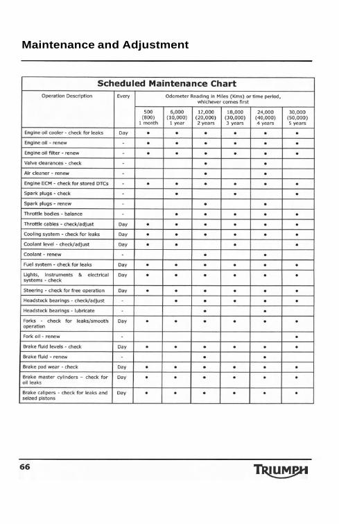
To maintain the motorcycle in a safe record, are contained in the booklet and reliable condition, the l~otorcycle Warranty and Service maintenance and adjustments Record, USA Models' supplied with outlined in this section must be this motorcycle. carried out as s~ecified in the schedule of daily checks, and also in line with the scheduled maintenance chart. The information that follows describes the procedures to follow when carrying out the daily checks and some simple maintenance and adjustment items. The US Environmental Protection Agency and the California Air Resources Board require that your motorcycle comply with exhaust emission and noise control standards during its useful service life. I n order to prevent possible prosecution under state and local ordinances, carry out the maintenance of the motorcycle in line with the periodic maintenance chart using genuine Triumph parts. Compliance with the requirements of the periodic maintenance chart is necessary in order to keep the emission and noise control warranties in effect.
knowledge will be required. Only an authorized Triumph dealer will have this knowledge and
Since incorrect or neglected maintenance can lead to a dangerous riding condition, always have an authorized Triumph deale carry out the schedule
Maintenance and Adjustment
malfunction. A
ather, terrain and geographical location affects maintenance. Th aintenance schedule should be adjusted to match the particula
e can lead to a dangerous ridin Triumph dealer carry out t h
Maintenance and Adjustment
Maintenance and Adjustment
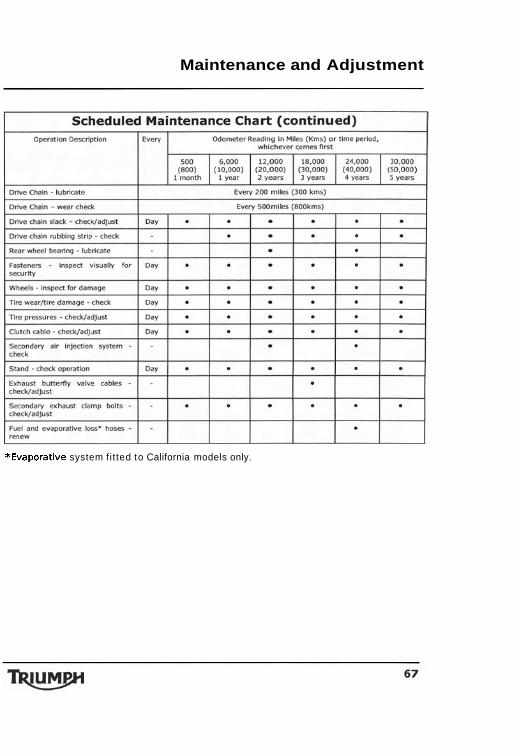
*Evaporative system fi t ted to California models only.
Maintenance and Adjustment
Engine Oil I n order for the engine, - transmiss- ion, and
clutch to function correctly, maintain the engine oil a t the correct level, and change the oil and oil filter in accordance with scheduled maintenance requirements.
Maintenance and Adjustment
Oil Level Inspection
-
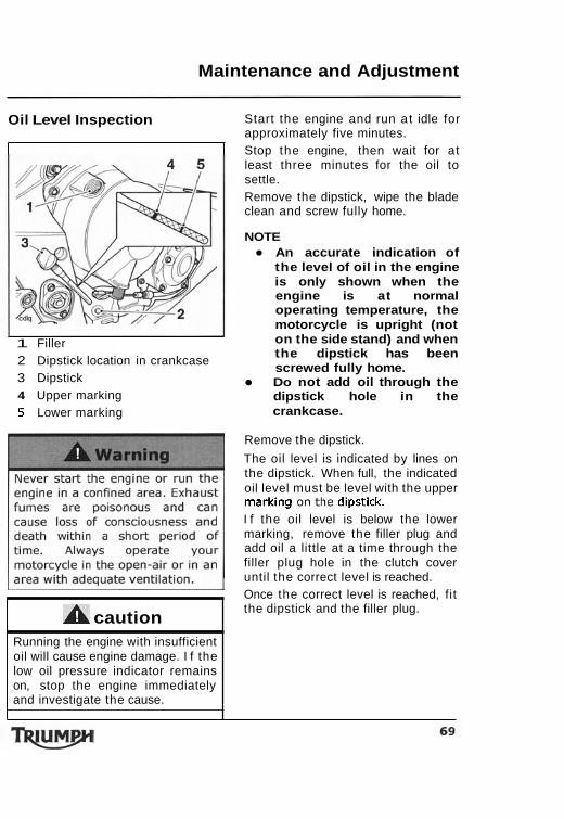
1 Filler 2 Dipstick location in crankcase 3 Dipstick 4 Upper marking 5 Lower marking
Start the engine and run a t idle for approximately five minutes. Stop the engine, then wait for at least three minutes for the oil to settle. Remove the dipstick, wipe the blade clean and screw fully home.
NOTE An accurate indication of the level of oil in the engine is only shown when the engine is at normal operating temperature, the motorcycle is upright (not on the side stand) and when the dipstick has been screwed fully home. Do not add oil through the dipstick hole in the crankcase.
Remove the dipstick.
The oil level is indicated by lines on the dipstick. When full, the indicated oil level must be level with the upper marking on the dipstick. I f the oil level is below the lower marking, remove the filler plug and add oil a little at a time through the filler plug hole in the clutch cover until the correct level is reached. Once the correct level is reached, fit
A caution Running the engine with insufficient oil will cause engine damage. I f the low oil pressure indicator remains on, stop the engine immediately and investigate the cause.
the dipstick and the filler plug.
Maintenance and Adjustment
Oil and Oil Filter Change Place an oil drain pan beneath the engine.
) Remove the oil drain plug.
tc. Contact with hot oil may caus
Unscrew and remove the oil filter using Triumph service tool
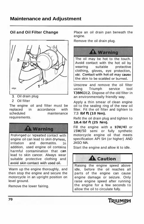
I 1 T3880312. Dispose of the old filter in 1 Oil drain plug an environmentally friendly way. 2 Oil filter Apply a thin smear of clean engine
The engine oil and filter must be oil t o the sealing ring of the new oil replaced in accordance with filter. Fit the oil filter and tighten to scheduled maintenance 7.3 Ibf ft (10 Nm). requirements. Refit the oil drain plug and tighten to
18.4 Ibf ft (25 Nrn). Fill the engine with a 10W/40 or 15W/50 semi or fully synthetic motorcycle engine oil that meets specification API SH (or higher) AND JASO MA. Start the engine and allow it to idle.
longea or repeatea contact engine oil can lead to skin dryn irritation and dermatitis. addition, used engine oil contai harmful contamination that can lead to skin cancer. Always wear suitable protective clothing and avoid skin contact with used oil.
Warm up the engine thoroughly, and then stop the engine and secure the motorcycle in an upright position on level ground.
Remove the lower fairing.
I
Raising the engine speed above idle, before the oil reaches all parts of the engine can cause engine damage or seizure. Only raise engine speed after running the engine for a few seconds t o allow the oil to circulate fully.
Maintenance and Adjustment
A cz I f the engine oil pressure is too low, the low oil pressure warning light will illuminate. I f this light stays on when the engine is running, stop the engine immediately and investigate the cause. Running the engine with low oil pressure will cause engine damage.
Ensure that the low oil pressure warning light extinguishes shortly after starting.
Turn off the ignition, check the oil level using the method previously described, and top up to between the minimum and maximum level lines on the dipstick. Refit the lower fairing.
Disposal of Used Engine Oil and Oil Filters
To protect the environment, do not pour oil on the ground, down sewers or drains, or into watercourses. Do not place used oil filters in with general waste. I f in doubt contact your local authority.
Oil Specification and Grade Triumph high performance fuel injected engines are designed to use 10W/40 or 15W/50 semi or fully synthetic motorcycle engine oil that meets specification A P I S H (or higher) AND JASO MA. Do not add any chemical additives to the engine oil. The engine oil also lubricates the clutch and any additives could cause the clutch to slip. Do not use mineral, vegetable, non- detergent oil, castor based oils o r any oil not conforming to the required specification. The use of these oils may cause instant, severe engine damage.
Maintenance and Adjustment
Cooling System Coolant Level Inspection To ensure efficient
before riding the motorcycle, and top up the coolant if the level is low.
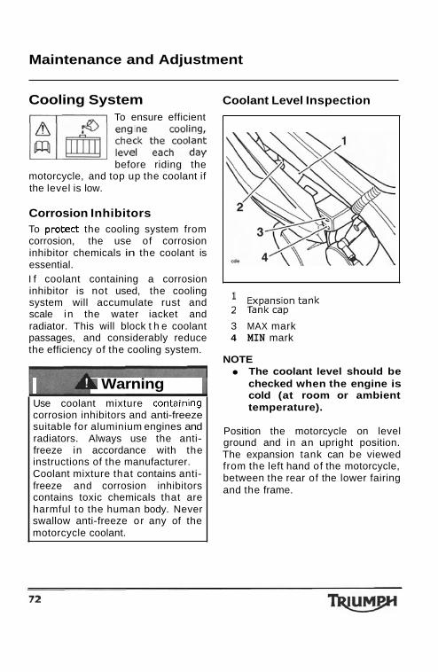
Corrosion Inhibitors To protect the cooling system from corrosion, the use of corrosion inhibitor chemicals in the coolant is essential. I f coolant containing a corrosion inhibitor is not used, the cooling Expansion tank system will accumulate rust and scale in the water iacket and * Tank cap radiator. This will block t h e coolant 3 MAX mark passages, and considerably reduce 4 MIN mark the efficiency of the cooling system.
NOTE
A Warning Use coolant mixture conta~ning corrosion inhibitors and anti-freeze suitable for aluminium engines and radiators. Always use the anti- freeze in accordance with the instructions of the manufacturer. Coolant mixture that contains anti- freeze and corrosion inhibitors contains toxic chemicals that are harmful to the human body. Never swallow anti-freeze or any of the motorcycle coolant.
The coolant level should be checked when the engine is cold (at room or ambient temperature).
Position the motorcycle on level ground and in an upright position. The expansion tank can be viewed from the left hand of the motorcycle, between the rear of the lower fairing and the frame.
Maintenance and Adjustment
Coolant Level Adjustment
hot, pressurised coolant will cause
Allow the engine to cool.
The expansion tank cap can be removed from the left hand of the motorcycle, between the rear of the lower fairing and the frame.
Remove the cap from the expansion tank, and add coolant mixture through the filler opening until the level reaches the 'MAX' mark. Refit the cap.
NOTE I f the coolant level is being checked because the coolant has overheated, also check the level in the radiator and top-up if necessary. In an emergency, water alone can be added to the cooling system. However, the coolant must be returned to the correct mixture ratio as soon as possible.
Coolant Change
Have the coolant changed by an authorized Triumph dealer in accordance with scheduled maintenance requirements.
Radiator Hoses Check the radiator hoses for cracks or deterioration, and hose clips for tightness in accordance with scheduled maintenance requirements. Have your authorized Triumph dealer replace any defective items.
A caution A year-round type of antifreeze is installed in the cooling system when the motorcycle leaves the factory. I t is coloured blue, contains a 50% solution of ethylene glycol, and has a freezing point of -31°F (-35OC).
Check the radiator grille and fins for obstructions by insects, leaves or mud. Clean off any obstructions with a stream of low-pressure water.
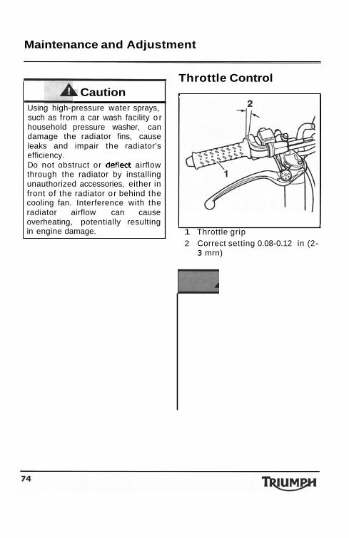
Maintenance and Adjustment
A Caution - Using high-pressure water sprays, such as from a car wash facility o r household pressure washer, can damage the radiator fins, cause leaks and impair the radiator's efficiency. Do not obstruct or deflect airflow through the radiator by installing unauthorized accessories, either in front of the radiator o r behind the cooling fan. Interference with the radiator airflow can cause overheating, potentially resulting in engine damage.
Throttle Control I I
I I
1 Throttle grip 2 Correct setting 0.08-0.12 in (2-
3 mrn)
Maintenance and Adjustment
throttle system checked by an authorized Triumph dealer if any changes are detected. Changes can be due to wear in the mechanism, which could lead to a sticking throttle. An incorrectly adjusted, sticking or stuck throttle will lead to loss of motorcycle control and an
Inspection Check that the throttle opens smoothly, without undue force and that it closes without sticking. Have your authorized Triumph dealer check the throttle system if a problem is detected or any doubt exists. Check that there is 0.08-0.12 in (2- 3 mm) of throttle grip free-play when lightly turning the throttle grip back and forth.
I f there is an incorrect amount of free-play, Triumph recommends that you have adjustments made by your authorized Triumph dealer. However, in an emergency, throttle adjustment may be made as follows:
!." . .. A Warning Use of the motorcycle with incorrectly adjusted, incorrectly routed, sticking or damaged throttle cables will interfere with the throttle function resulting in loss of motorcycle control and an accident. To avoid incorrect adjustment, incorrect routing, or continued use of a sticking or damaged throttle, always have your throttle checked and adjusted by your authorized Triumph dealer.
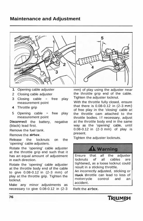
Maintenance and Adjustment
1
1 Opening cable adjuster 2 Closing cable adjuster 3 Closing cable - free play
measurement point 4 Throttle grip
5 Opening cable - free play measurement point
Disconnect the battery, negative (black) lead first. Remove the fuel tank. Remove the airbox. Release the locknuts on the 'opening' cable adjusters. Rotate the 'opening' cable adjuster at the throttle grip end such that it has an equal amount of adjustment in each direction. Rotate the 'opening' cable adjuster at the throttle body end of the cable to give 0.08-0.12 in (2-3 mm) of play at the throttle grip. Tighten the locknut. Make any minor adjustments as necessary to give 0.08-0.12 in (2-3
I rnm) of play using the adjuster near the throttle grip end of the cable. Tighten the adjuster locknut. With the throttle fully closed, ensure that there is 0.08-0.12 in (2-3 rnm) of free play in the 'closing' cable at the throttle cam attached to the throttle bodies. I f necessary, adjust at the throttle body end in the same way as the 'opening' cable, until 0.08-0.12 in (2-3 mm) of play is present. Tighten the adjuster locknuts.
n incorrectly adjusted, sticking or tuck throttle can lead to loss of
cle control and an
Refit the airbox.
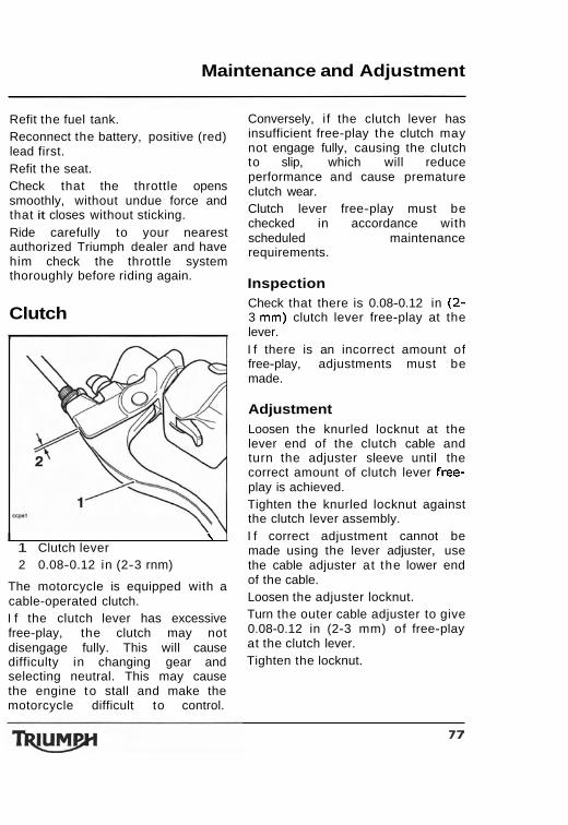
Maintenance and Adjustment
Refit the fuel tank. Reconnect the battery, positive (red) lead first. Refit the seat. Check that the throttle opens smoothly, without undue force and that it closes without sticking. Ride carefully to your nearest authorized Triumph dealer and have him check the throttle system thoroughly before riding again.
Clutch
I \ I 1 Clutch lever 2 0.08-0.12 in (2-3 rnm)
The motorcycle is equipped with a cable-operated clutch. I f the clutch lever has excessive free-play, the clutch may not disengage fully. This will cause difficulty in changing gear and selecting neutral. This may cause the engine to stall and make the motorcycle difficult to control.
Conversely, i f the clutch lever has insufficient free-play the clutch may not engage fully, causing the clutch to slip, which will reduce performance and cause premature clutch wear. Clutch lever free-play must be checked in accordance with scheduled maintenance requirements.
Inspection Check that there is 0.08-0.12 in (2- 3 mm) clutch lever free-play at the lever. I f there is an incorrect amount of free-play, adjustments must be made.
Adjustment Loosen the knurled locknut at the lever end of the clutch cable and turn the adjuster sleeve until the correct amount of clutch lever free- play is achieved. Tighten the knurled locknut against the clutch lever assembly. I f correct adjustment cannot be made using the lever adjuster, use the cable adjuster at the lower end of the cable. Loosen the adjuster locknut. Turn the outer cable adjuster to give 0.08-0.12 in (2-3 mm) of free-play at the clutch lever. Tighten the locknut.
Maintenance and Adjustment
Drive Chain For safety and to prevent excessive
wear the drive chain must be checked, adjusted and lubricated in accordance with scheduled maintenance requirements. Checking, adjustment and lubrication must be carried out more frequently for extreme conditions such as salty or heavily gritted roads. I f the chain is badly worn or incorrectly adjusted (either too loose o r too tight) the chain could jump off the sprockets or break. Therefore, always replace worn o r damaged chains using genuine Triumph parts supplied by an authorized Triumph dealer.
A loose or worn chain, o r a chain that breaks or jumps off the sprockets could catch on the engine sprocket or lock the rear wheel. A chain that snags on the engine sprocket will injure the rider and lead to loss of motorcycle control and an accident. Similarly, locking the rear wheel will lead to loss of motorcycle control and an accident.
Chain Lubrication
Lubrication is necessary every 200 miles and also after riding in wet weather, on wet roads, or any t ime that the chain appears dry. Use the special chain lubricant as recommended in the specification section. Apply lubricant to the sides of the rollers then allow the motorcycle t o stand unused for a t least 8 hours (overnight is ideal). This will allow the oil to penetrate to the chain O- rings etc. Before riding, wipe off any excess oil. I f the chain is especially dirty, clean first and then apply oil as mentioned above.
Do not use a pressure wash to clean the chain as this may cause
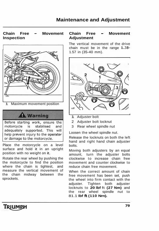
Maintenance and Adjustment
Chain Free - Movement Chain Free - Movement Inspection Adjustment
The vertical movement of the drive I chain must be in the range 1.38-
I I 1 Maximum movement position
help prevent injury to the operato
Place the motorcycle on a level surface and hold it in an upright position with no weight on it.
Rotate the rear wheel by pushing the the motorcycle to find the position where the chain is tightest, and measure the vertical movement of the chain midway between the sprockets.
1.57 in (35-40 mm).
I I
1 Adjuster bolt 2 Adjuster bolt locknut 3 Rear wheel spindle nut
Loosen the wheel spindle nut. Release the locknuts on both the left hand and right hand chain adjuster bolts. Moving both adjusters by an equal amount, turn the adjuster bolts clockwise to increase chain free movement and counter clockwise to reduce chain free movement. When the correct amount of chain free movement has been set, push the wheel into firm contact with the adjuster. Tighten both adjuster locknuts to 20 lbf ft (27 Nm) and the rear wheel spindle nut to 81.1 Ibf ft (110 Nrn).
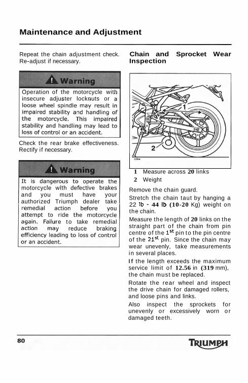
Maintenance and Adjustment
Repeat the chain adjustment check. Chain and Sprocket Wear Re-adjust if necessary. Inspection
Operation of the motorcycle with insecure adjuster locknuts or
Check the rear brake effectiveness. Rectify i f necessary.
motorcycle with defective brakes and you must have your authorized Triumph dealer take
re t o take remedial y reduce braking
I I 1 Measure across 20 links 2 Weight
Remove the chain guard. Stretch the chain taut by hanging a 22 Ib - 44 Ib (10-20 Kg) weight on the chain. Measure the length of 20 links on the straight part o f the chain from pin centre of the lSt pin t o the pin centre of the 21St pin. Since the chain may wear unevenly, take measurements in several places. I f the length exceeds the maximum service limit o f 12.56 in (319 mm), the chain must be replaced. Rotate the rear wheel and inspect the drive chain for damaged rollers, and loose pins and links. Also inspect the sprockets for unevenly or excessively worn o r damaged teeth.
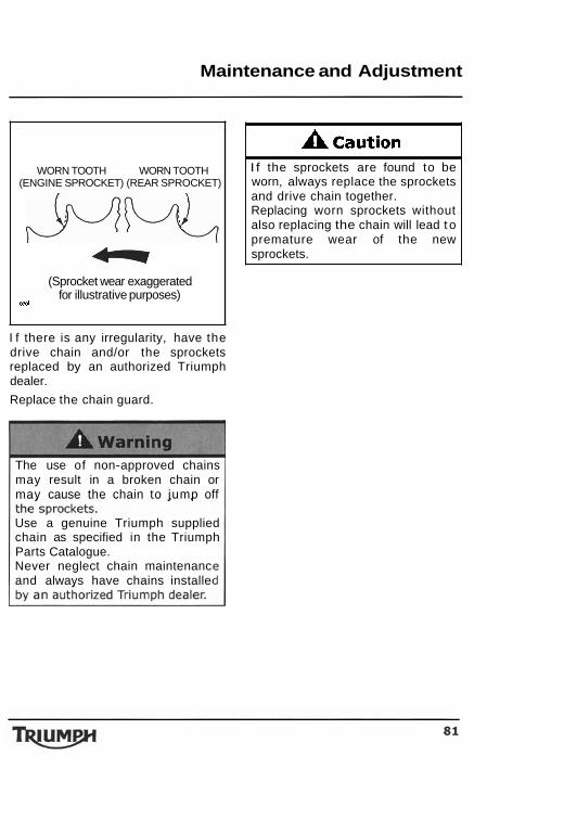
Maintenance and Adjustment
WORN TOOTH WORN TOOTH (ENGINE SPROCKET) (REAR SPROCKET) ww -
(Sprocket wear exaggerated
srm for illustrative purposes)
I f there is any irregularity, have the drive chain and/or the sprockets replaced by an authorized Triumph dealer.
Replace the chain guard.
The use of non-approved chains may result in a broken chain or may cause the chain to jump off
Use a genuine Triumph supplied chain as specified in the Triumph Parts Catalogue. Never neglect chain maintenanc and always have chains installe
A caution I f the sprockets are found to be worn, always replace the sprockets and drive chain together. Replacing worn sprockets without also replacing the chain will lead t o premature wear of the new sprockets.
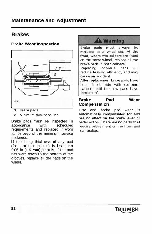
Maintenance and Adjustment
Brakes
Brake Wear Inspection
I I 1 Brake pads 2 Minimum thickness line
Brake pads must be inspected in accordance with scheduled requirements and replaced if worn to, or beyond the minimum service thickness. I f the lining thickness of any pad (front or rear brakes) is less than 0.06 in (1.5 rnm), that is, if the pad has worn down to the bottom of the grooves, replace all the pads on the wheel.
on the same wheel, replace all the brake pads in both calipers. Replacing individual pads will reduce braking efficiency and may cause an accident. After replacement brake pads have been fitted, ride with extreme caution until the new pads have
Brake Pad Wear Compensation Disc and brake pad wear is automatically compensated for and has no effect on the brake lever or pedal action. There are no parts that require adjustment on the front and rear brakes.
Maintenance and Adjustment
~t the DraKe lever or peaal reels soft when i t is applied, or i f the lever/pedal travel becomes excessive, there may be air in the brake pipes and hoses or the brakes may be defective. I t is dangerous to operate the motorcycle under such conditions and your authorized Triumph dealer must rectify the fault before
Riding with defective brakes m
Disc Brake Fluid Inspect the level o f brake fluid in both reservoirs and change the brake fluid in accordance with scheduled maintenance requirements. Use only DOT 4 fluid as recommended in the specification section. The brake fluid must also be changed i f i t becomes, or is suspected of having become contaminated with moisture or any other contaminants.
absorbed moisture will greatly ce the boiling point of the
fluid causing a reduction in
se of this, always replace fluid in accordance with
maintenance
lways use new brake fluid from a ealed container and never use
one which has been
not mix different brands or rades o f brake fluid. heck for fluid leakage around
brake fittings, seals and joints and also check the brake hoses for splits, deterioration and damage. Always rectify any faults before
Failure t o observe and act upon any of these items may cause a dangerous riding condition leading

Maintenance and Adjustment
Brake Fluid Level Inspection and Adjustment
I I 1 Front brake fluid reservoir,
upper level line 2 Lower level line 3 Safety clip
The brake fluid level in the reservoirs must be kept between the upper and lower level lines (reservoir held horizontal). Remove the safety clip (front only). Fill the reservoir t o the upper level line using new DOT 4 fluid from a sealed container. Refit the reservoir cover ensuring that the diaphragm seal is correctly fitted. Refit the safety clip.
I f there has been an appreciable drop in the level of the f l u~d in either fluid reservoir, consult your authorized Triumph dealer for advice before riding. Riding with depleted brake fluid levels, or with a brake fluid leak is dangerous and will cause reduced brake performance potentially leading t o loss of motorcycle control and an accident.
I 1 Rear brake fluid reservoir, upper
level line 2 Lower level line
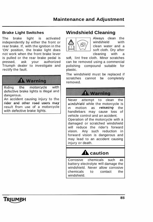
Maintenance and Adjustment
Brake Light Switches
The brake light is activated independently by either the front or rear brake. If, with the ignition in the 'ON' position, the brake light does not work when the front brake lever is pulled or the rear brake pedal is pressed, ask your authorized Triumph dealer to investigate and rectify the fault.
An accident causing injury to the rider and other road users may
Windshield Cleaning Always clean the windshield with clean water and a soft cloth. Dry after cleaning with a
soft, l int free cloth. Minor scratches can be removed using a commercial polishing compound suitable for plastic. The windshield must be replaced if scratches cannot be completely removed.
I
Never attempt to clean the w~ndshield while the motorcycle is In motion as releasing the handlebars may cause loss of vehicle control and an accident. Operation of the motorcycle with a damaged or scratched windshield will reduce the rider's forward vision. Any such reduction in forward vision is dangerous and may lead to an accident causing injury or death.
A caution Corrosive chemicals such as battery electrolyte will damage the windshield. Never allow corrosive chemicals to contact the windshield.
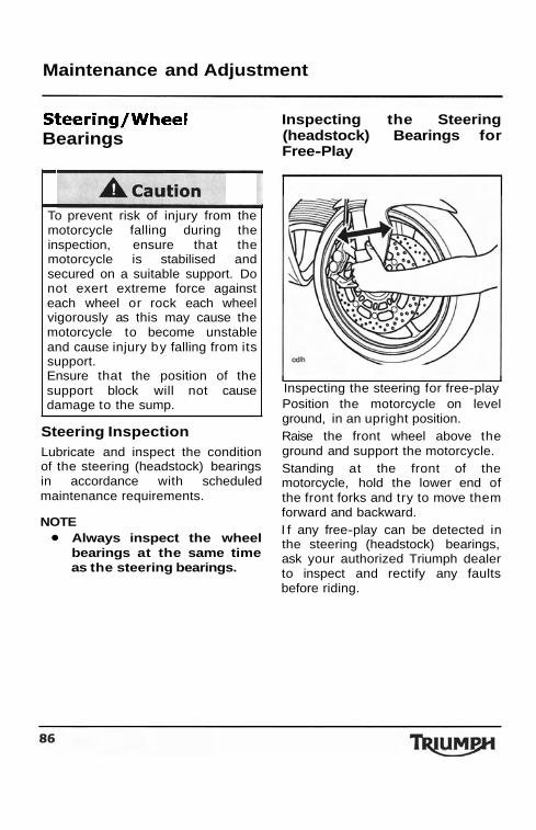
Maintenance and Adjustment
Steering/Wheel Bearings
I
I
To prevent risk of injury from the motorcycle falling during the inspection, ensure that the motorcycle is stabilised and secured on a suitable support. Do not exert extreme force against each wheel or rock each wheel vigorously as this may cause the motorcycle to become unstable and cause injury by falling from its support. Ensure that the position of the support block will not cause damage to the sump.
Steering Inspection Lubricate and inspect the condition of the steering (headstock) bearings in accordance with scheduled maintenance requirements.
NOTE Always inspect the wheel bearings at the same time as the steering bearings.
Inspecting the Steering (headstock) Bearings for Free-Play
I I Inspecting the steering for free-play Position the motorcycle on level ground, in an upright position. Raise the front wheel above the ground and support the motorcycle. Standing at the front of the motorcycle, hold the lower end of the front forks and try to move them forward and backward. I f any free-play can be detected in the steering (headstock) bearings, ask your authorized Triumph dealer to inspect and rectify any faults before riding.
L I 1 Gear change lights 2 Display screen 3 Scroll button 4 Set button 5 Trip button
Pressing the 'Set' button at this point will return the instruments to their normal mode of operation, without adjusting the gear change lights limits. To change the setting, press the 'Scroll' button. The clock display will now show 'A1000'.
General Information
I I 1 Gear change lights 2 Display screen 3 Scroll button 4 Set button 5 Trip button
To change the setting in increments of 1,000 rprn, press the 'Scroll' button again. Each individual press will then increase the setting in increments of 1,000 rpm, up to a limit of 14,000 rpm. As the limit cannot exceed 14,00Orpm, when 14,000 rpm is reached the limit will return to 4,000 rpm. When the correct setting is shown press the 'set' button to confirm. The clock display will now show 'A100'.
Maintenance and Adjustment
incorrectly adjusted or defectiv steering (headstock) bearings i
Wheel Bearings Inspection
I f the wheel bearings in the front or rear wheel allow play in the wheel hub, are noisy, o r i f the wheel does not turn smoothly, have your authorized Triumph dealer inspect the wheel bearings. The wheel bearings must be inspected a t the intervals specified in
R~~~~~ the support and place the the scheduled maintenance chart.
motorcycle on the side stand. Position the motorcycle on level ground, in an upright position. Raise the front wheel above the ground and support the motorcycle. Standing a t the side of the motorcycle, gently rock the top of the front wheel from side to side. I f any free-play can be detected, ask your authorized Triumph dealer to inspect and rectify any faults before riding. Reposition the lifting device and repeat the procedure for the rear wheel.
- peration with worn or damage
ront or rear wheel bearings is angerous and may cause
aired handling and instability accident. I f in doubt,
torcycle inspected by ed Triumph dealer
Remove the support and place the motorcycle on the side stand.
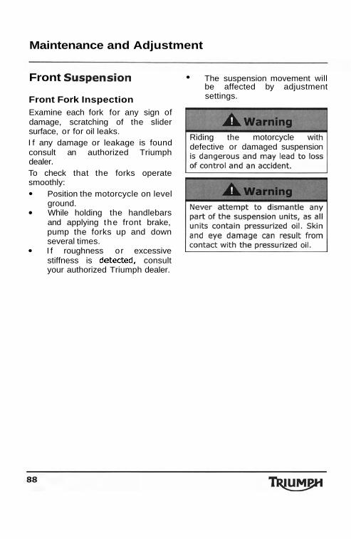
Suspension
detected,
1 s t LED
2nd LED
3rd LED
4th
5th 6th and 7th LEDs
Gear change lights
LED mode: All seven lights screen (3 LED mode
remain
set Trip button
Maintenance and Adjustment General Information
Front The suspension movement will be affected by adjustment
Front Fork Inspection settings.
Examine each fork for any sign of damage, scratching of the slider surface, or for oil leaks.
Riding the motorcycle witI f any damage or leakage is found defective or damaged suspensio consult an authorized Triumph dealer. To check that the forks operate smoothly:
Position the motorcycle on level ground. While holding the handlebars and applying the front brake, pump the forks up and down several times.
LED RPM
3,000 rprn before set change-up
speed
2,250 rprn before set change-up
speed
1,500 rprn before set change-up
speed
LED 750 rpm before set change-up
speed
At set change-up speed
I f roughness or excessive The gear change lights will go stiffness is consult out in the reverse of the order your authorized Triumph dealer. in which they illuminate.
3 LED mode: The three middle lights illuminate when the set limit is reached, and remain illuminated until the engine speed drops below the set limit. 7 illuminate when the set limit is reached, and illuminated until the engine speed drops below the limit.
OFF mode: The gear change lights can be set to OFF.
The gear change lights will not operate below 4,000 rprn to avoid the lights operating at idle, and will not operate above 14,000 rpm.
Adjusting Gear Change light Modes
To adjust the gear change light modes, turn the ignition to the 'ON' position. Press the 'Trip' and 'Scroll' buttons simultaneously for 4 seconds, after 4 seconds the current mode will be displayed.
shown)
3 Scroll button 4 Set button 5
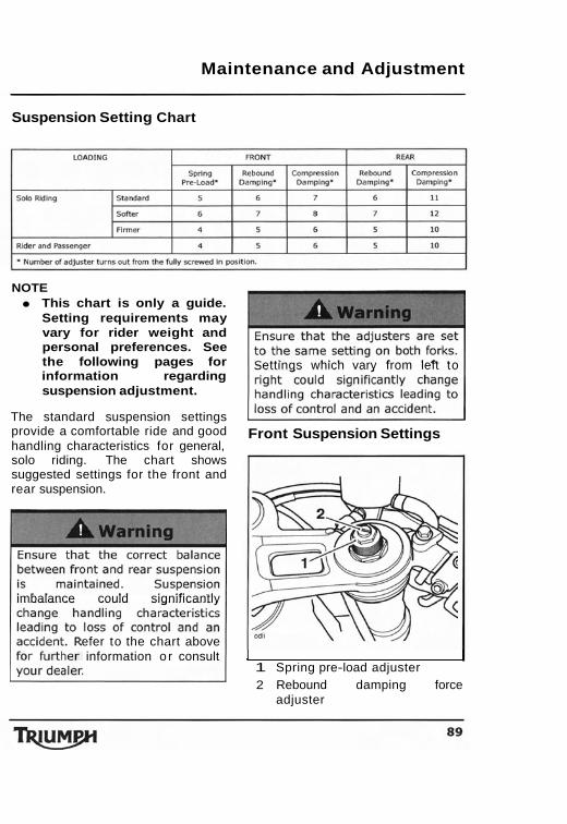
Maintenance and Adjustment
Suspension Setting Chart
NOTE This chart is only a guide. Setting requirements may vary for rider weight and personal preferences. See the following pages for information regarding suspension adjustment.
The standard suspension settings provide a comfortable ride and good handling characteristics for general, solo riding. The chart shows suggested settings for the front and rear suspension.
imbalance could significantly
efer to the chart above information o r consult
ettings which vary from left to
Front Suspension Settings
1 1 Spring pre-load adjuster 2 Rebound damping force
adjuster
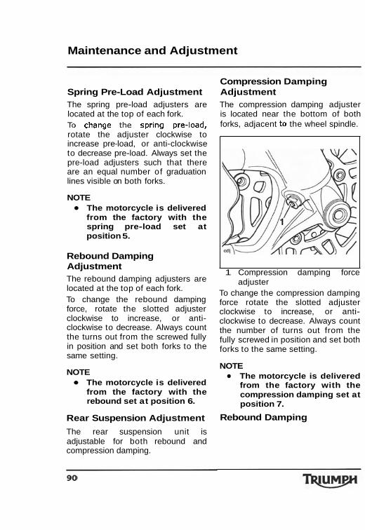
Maintenance and Adjustment
Compression Damping Spring Pre-Load Adjustment Adjustment The spring pre-load adjusters are The compression damping adjuster located at the top of each fork. is located near the bottom of both TO change the spring pre-load, forks, adjacent to the wheel spindle. rotate the adjuster clockwise to increase pre-load, or anti-clockwise to decrease pre-load. Always set the pre-load adjusters such that there are an equal number of graduation lines visible on both forks.
NOTE The motorcycle is delivered from the factory with the spring pre-load set at position 5.
Rebound Damping Adjustment The rebound damping adjusters are located at the top of each fork. To change the rebound damping force, rotate the slotted adjuster clockwise to increase, or anti- clockwise to decrease. Always count the turns out from the screwed fully in position and set both forks to the same setting.
NOTE The motorcycle is delivered from the factory with the rebound set at position 6.
Rear Suspension Adjustment
The rear suspension unit is adjustable for both rebound and compression damping.
1 Compression damping force adjuster
To change the compression damping force rotate the slotted adjuster clockwise to increase, or anti- clockwise to decrease. Always count the number of turns out from the fully screwed in position and set both forks to the same setting.
NOTE The motorcycle is delivered from the factory with the compression damping set at position 7.
Rebound Damping
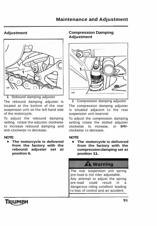
Maintenance and Adjustment
Adjustment
1 I 1 Rebound damping adjuster
The rebound damping adjuster is located a t the bottom of the rear suspension unit on the left hand side of the motorcycle. To adjust the rebound damping setting, rotate the adjuster clockwise to increase rebound damping and anti-clockwise t o decrease.
NOTE The motorcycle is delivered from the factory with the rebound adjuster set at position 6.
Compression Damping Adjustment
I I 1 Compression damping adjuster
The compression damping adjuster is situated adjacent t o the rear suspension unit reservoir. To adjust the compression damping setting rotate the slotted adjuster clockwise to increase, or anti- clockwise t o decrease.
NOTE The motorcycle is delivered from the factory with the compression damping set at position 11.
The rear suspension unit spring pre-load is not rider adjustable. Any attempt to adjust the spring pre-load could result in a dangerous riding condition leading t o loss of control and an accident.
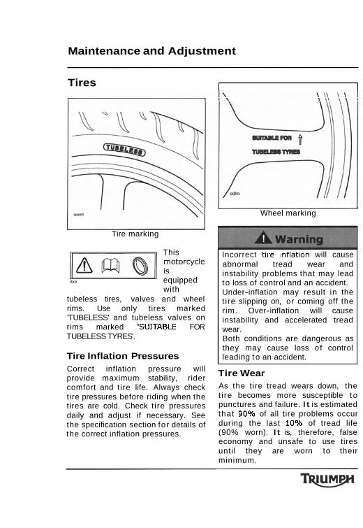
Maintenance and Adjustment
Tires
Tire marking
This ml ;OtOrcycle - equipped with
tubeless tires, valves and wheel rims. Use only tires marked 'TUBELESS' and tubeless valves on rims marked 'SUJTABLE FOR TUBELESS TYRES'.
Tire Inflation Pressures Correct inflation pressure will provide maximum stability, rider comfort and t ire life. Always check tire pressures before riding when the tires are cold. Check t ire pressures daily and adjust if necessary. See the specification section for details of the correct inflation pressures.
I I Wheel marking
Incorrect tlre lnflatlon will cause abnormal tread wear and instability problems that may lead to loss of control and an accident. Under-inflation may result in the t ire slipping on, or coming off the rim. Over-inflation will cause instability and accelerated tread wear. Both conditions are dangerous as they may cause loss o f control leading t o an accident.
Tire Wear As the tire tread wears down, the t i re becomes more susceptible t o punctures and failure. It is estimated that 90% of all tire problems occur during the last 10% of tread life (90% worn). It is, therefore, false economy and unsafe to use tires until they are worn to their minimum.
Maintenance and Adjustment
Minimum Recommended Tread Depth I n accordance with the periodic maintenance chart, measure the depth of the tread with a depth gauge, and replace any tire that has worn to, or beyond the minimum allowable tread depth specified in the table below:
- Only operate this Triumph motorcycle at high speed in closed course on-road competition or on closed course race tracks. High speed operation should only then be attempted by riders who have been instructed in the techniques necessary for high speed riding and are familiar with the motorcycle's characteristics in all conditions. High speed operation in any other circumstances is dangerous and will lead to loss of motorcycle control and an accident.
Under 80 mph (130 km/h)
Over 80 mph (130 km/h)
Operation with excessively wor tires is hazardous and wil adversely affect traction, stabilit and handling which may lead t loss of control and an accident. When tubeless tires becom punctured, leakage is often ve slow. Always inspect tires ve closely for punctures. Check th tires for cuts, embedded nails o other sharp objects. Ope with punctured or damaged will adversely affect motor stability and handling which lead to loss of control or accident.
0.08 in (2 mm)
Rear 0.12 in (3 mm) Front 0.08 in (2 mm)
Maintenance and Adjustment
/continued Check the r ims for dents or deformation. Operation with damaged or defective wheels or tlres 1s dangerous and loss of motorcycle control or an accident could result. Always consult your authorized Triumph dealer for tire replacement, or for a safety inspection of the tires.
Tire Replacement All Triumph motorcycles are carefully and extensively tested in a range of riding conditions to ensure that the most effective tire combinations are approved for use on each model. It is essential that approved tires, fitted in approved combinations, are used when purchasing replacement tires. The use of non-approved tires, or approved tires in non-approved combinations, may lead to motorcycle instability and an accident. See the specification section for details of approved tire combinations. Always have tires fitted and balanced by your authorized Triumph dealer who has the necessary training and skills to ensure safe, effective fitment.
Do not install tube-type tires on tubeless rims. The bead will not seat and the tires could slip on the rims, causing rapid t ire deflation that may result in a loss of vehicle control and an accident. Never install an inner tube inside a tubeless tire. This will cause friction inside the t ire and the resulting heat build-up may cause the tube to burst resulting in rapid tire deflation, loss of vehicle control and an accident.
b
I
~r tire aamage IS suspeccea, sucn as after striking the kerb, ask your authorized Triumph dealer to inspect the tire both internally and externally. Remember, tire damage may not always be visible from the outside. Operation of the motorcycle with damaged tires could lead to loss of control and an accident.
arning -
Maintenance and Adjustment
for the tires t o seat t o the r im roximately 24 hours). During seating period, ride cautiously
Initially, the new tires will not produce the same handling characteristics as the worn tires and the rider must allow adequate riding distance (approximately 100 miles) to become accustomed to the new handling characteristics. 24 hours after fitting, the tire pressures must be checked and adjusted, and the tires examined for correct seating. Rectification must be carried out as necessary. The same checks and adjustments must also be carried out when 100 miles have been travelled after
ires must be replaced after such use as continued use of a
tire may lead t o , loss of control and an
may cause instability leadlng t o loss of control and an accident. When wheel balancing is required, such as after tire replacement, see your authorized Triumph dealer. Only use self-adhesive weights. Clip on weights may damage the wheel and tire resulting in t ~ r e deflation, loss of control and an
Maintenance and Adjustment
Battery
've off explosive arks, flames and Provide adequate charging or using
attery In an enclosed space. he battery contains sulphuric acid lectrolyte). Contact with skin or
may cause severe burns. protective clothing and a
ctrolyte gets on your skin,
ush with water for a t least 15 inutes and SEEK MEDICAL
N IMMEDIATELY. lyte is swallowed, drink ntities of water and SEEK
EACH OF CHILDREN.
which would
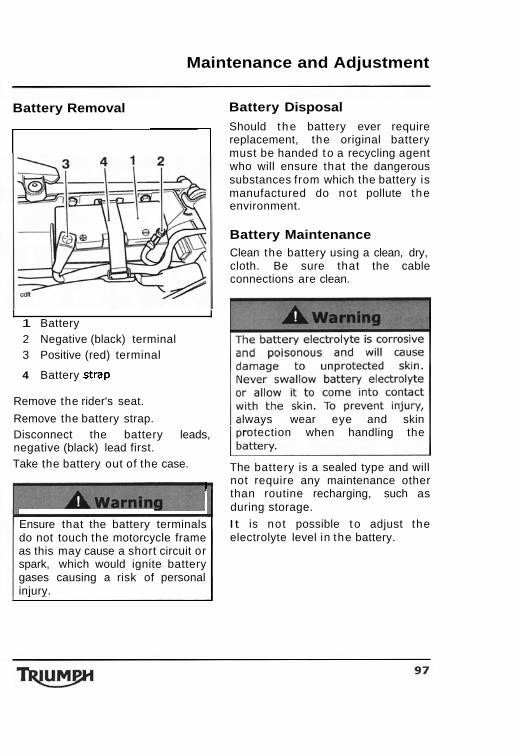
Maintenance and Adjustment
Battery Removal
9
I I 1 Battery 2 Negative (black) terminal 3 Positive (red) terminal
4 Battery strap
Remove the rider's seat.
Remove the battery strap. Disconnect the battery leads, negative (black) lead first. Take the battery out of the case.
r
Ensure that the battery terminals do not touch the motorcycle frame as this may cause a short circuit or spark, which would ignite battery gases causing a risk of personal injury.
Battery Disposal Should the battery ever require replacement, the original battery must be handed to a recycling agent who will ensure that the dangerous substances from which the battery is manufactured do not pollute the environment.
Battery Maintenance Clean the battery using a clean, dry, cloth. Be sure that the cable connections are clean.
lways wear eye and skin rotection when handling the
The battery is a sealed type and will not require any maintenance other than routine recharging, such as during storage.
It is not possible t o adjust the electrolyte level in the battery.
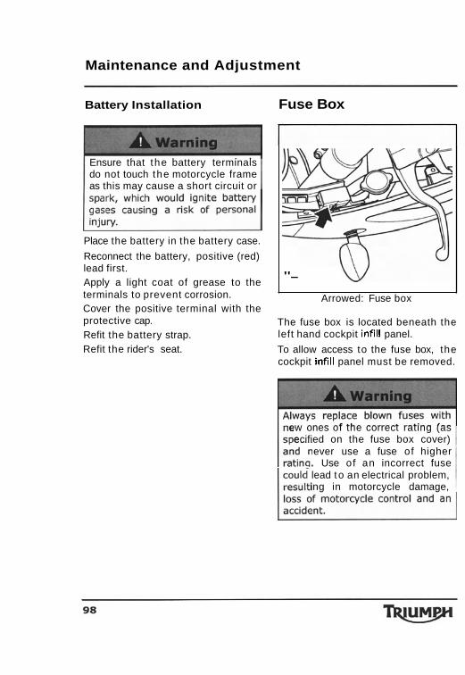
Maintenance and Adjustment
Battery Installation Fuse Box
Ensure that the battery terminals do not touch the motorcycle frame as this may cause a short circuit or
Refit the rider's seat.
Place the battery in the battery case.
Reconnect the battery, positive (red) lead first. Apply a light coat of grease to the terminals to prevent corrosion.
To allow access to the fuse box, the cockpit infill panel must be removed.
"-
ew ones of the correct rating (as ecified on the fuse box cover)
ever use a fuse of higher . Use of an incorrect fuse lead to an electrical problem, ing in motorcycle damage,
Arrowed: Fuse box Cover the positive terminal with the protective cap. The fuse box is located beneath the Refit the battery strap. left hand cockpit infill panel.
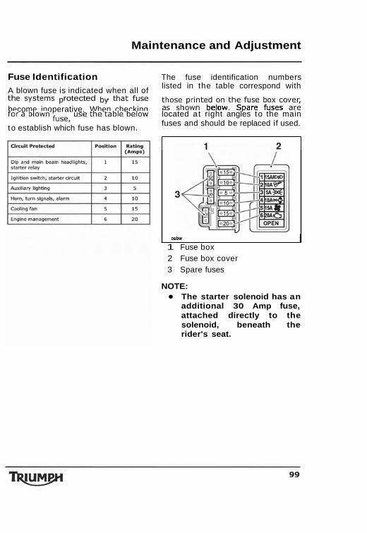
Maintenance and Adjustment
Fuse Identification The fuse identification numbers listed in the table correspond with
A blown fuse is indicated when all of those printed on the fuse box cover, the systems protected that fuse as shown below. Spare fuses are become inoperative. When checking
located a t right angles to the main for a blown use the table below fuses and should be replaced if used. to establish which fuse has blown.
mbw
1 Fuse box 2 Fuse box cover 3 Spare fuses
NOTE: The starter solenoid has an additional 30 Amp fuse, attached directly to the solenoid, beneath the rider's seat.
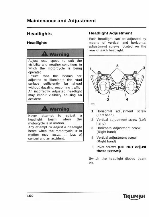
Maintenance and Adjustment
Headlights
Headlights
Adjust road speed to suit the visibility and weather conditions in which the motorcycle is being operated. Ensure that the beams are adjusted to illuminate the road surface sufficiently far ahead without dazzling oncoming traffic. An incorrectly adjusted headlight may impair visibility causing an accident.
Any attempt t o adjust a headlight beam when the motorcycle is in
result in loss of
Headlight Adjustment
Each headlight can be adjusted by means of vertical and horizontal adjustment screws located on the rear of each headlight.
I I 1 Horizontal adjustment screw
(Left hand) 2 Vertical adjustment screw (Left
hand) 3 Horizontal adjustment screw
(Right hand)
4 Vertical adjustment screw (Right hand)
5 Pivot screws (DO NOT adjust these screws)
Switch the headlight dipped beam on.
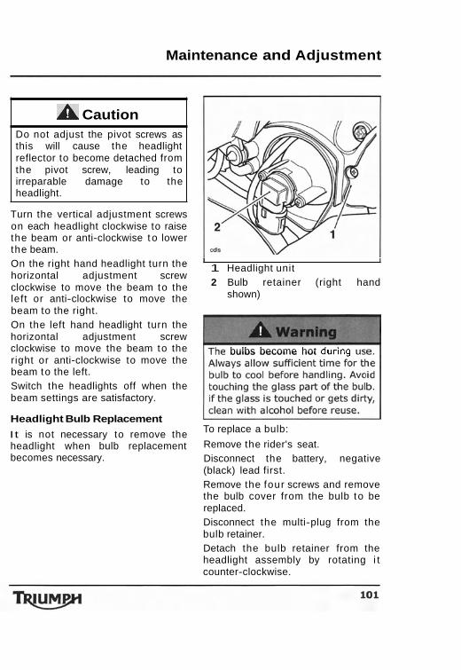
Maintenance and Adjustment
A Caution Do not adjust the pivot screws as this will cause the headlight reflector to become detached from the pivot screw, leading to irreparable damage to the headlight.
Turn the vertical adjustment screws on each headlight clockwise to raise the beam or anti-clockwise t o lower the beam. On the right hand headlight turn the horizontal adjustment screw clockwise to move the beam to the left or anti-clockwise to move the beam to the right. On the left hand headlight turn the horizontal adjustment screw clockwise to move the beam to the right or anti-clockwise to move the beam to the left. Switch the headlights off when the beam settings are satisfactory.
Headlight Bulb Replacement
I t is not necessary to remove the headlight when bulb replacement becomes necessary.
I I 1 Headlight unit 2 Bulb retainer (right hand
shown)
bulbs become hot durlng u
To replace a bulb:
Remove the rider's seat. Disconnect the battery, negative (black) lead first. Remove the four screws and remove the bulb cover from the bulb to be replaced. Disconnect the multi-plug from the bulb retainer. Detach the bulb retainer from the headlight assembly by rotating i t counter-clockwise.
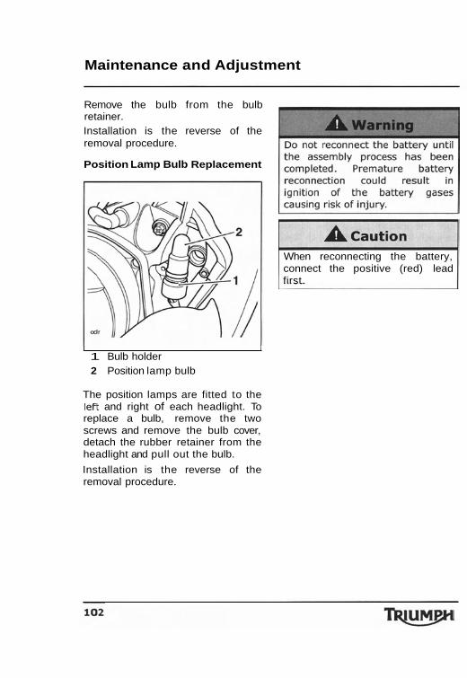
Maintenance and Adjustment
Remove the bulb from the bulb retainer. Installation is the reverse of the removal procedure.
Position Lamp Bulb Replacement
I I 1 Bulb holder 2 Position lamp bulb
The position lamps are fitted to the lei7 and right of each headlight. To replace a bulb, remove the two screws and remove the bulb cover, detach the rubber retainer from the headlight and pull out the bulb.
Installation is the reverse of the removal procedure.
When reconnecting the battery, connect the positive (red) lead first.
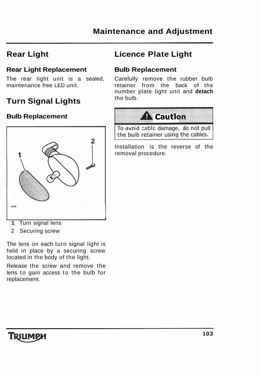
Maintenance and Adjustment
Rear Light Licence Plate Light
Rear Light Replacement Bulb Replacement The rear light unit is a sealed, Carefully remove the rubber bulb maintenance free LED unit. retainer from the back of the
number plate light unit and detach
Turn Signal Lights the bulb.
Bulb Replacement Cautic To avola came damage, ao not pull
1 Turn signal lens
-
2
1
2 Securing screw
Installation is the reverse of the removal procedure.
The lens on each turn signal light is held in place by a securing screw located in the body of the light.
Release the screw and remove the lens to gain access to the bulb for replacement.
Maintenance and Adjustment
Cleaning Frequent, regular cleaning is an essential part of the maintenance of your motorcycle. I f regularly cleaned, the appearance will be preserved for many years. Cleaning with warm water containing an automotive cleaner is essential a t all times but particularly so after exposure to sea breezes, sea water, dusty or muddy roads and in winter when roads are treated for ice and snow. Although, under the terms of your motorcycle warranty, cover is provided against the corrosion of certain items, the owner is expected to observe this reasonable advice which will safeguard against corrosion and enhance the appearance o f the motorcycle. Do not use household detergent, as the use of such products will lead to premature corrosion.
Preparation for Washing Before washing, precautions must be taken to keep water off the following
Where to be Careful Avoid spraying water with any great force near the following places:
Instruments. Brake cylinders and brake calipers. Under the fuel tank. Headstock bearings. Air intake duct above the headlights.
Any water sprayed around the air intake duct could enter the airbox and engine, causing damage t o
aution . - Use of high-pressure spray washers is not recommended. When using pressure washers, water may be forced into bearings and other components causing premature wear from corrosion and loss of lubrication.
places. NOTE
Rear opening of the mufflers: Cover . Use of soaps that are highly with a plastic bag secured with alkaline will leave a residue rubber bands. on painted surfaces, and Clutch and brake levers, switch may also cause water housings on the handlebar: Cover spotting. Always use a low with plastic bags. alkaline soap to aid the Ignition switch: Cover the keyhole cleaning process. with tape.
Maintenance and Adjustment
After Washing Remove the plastic bags and tape, and clear the air intakes. Lubricate the pivots, bolts and nuts. Test the brakes before motorcycle operation. Start the engine and run it for 5 minutes. Ensure adequate ventilation for the exhaust fumes. Use a dry cloth to absorb water residue. Do not allow water to stand o n the machine as this will lead to corrosion.
n accident could result. Clean the
Unpainted Aluminium Items I tems such as brake and clutch levers must be correctly cleaned to preserve their appearance. Use a proprietary brand of aluminium cleaner which does not contain abrasive o r caustic elements. Clean aluminium items regularly, in particular after use in inclement weather, where the components must be hand washed and dried each t ime the machine is used. Warranty claims due to inadequate maintenance will not be allowed.
Cleaning of the Exhaust System
All parts of the exhaust system o f your motorcycle must be cleaned regularly t o avoid a deterioration of its appearance. These instructions can be applied t o chrome, brushed stainless steel and carbon fibre components alike.
NOTE a The exhaust system must
be cool before washing to prevent water spotting.
Washing Prepare a mixture of water and mild soap. Do not use a highly alkaline soap as commonly found a t commercial car washes because it leaves a residue. Wash the exhaust system with a soft cloth. Do not use an abrasive scouring pad or steel wool. They will damage the finish. Rinse the exhaust system thoroughly. Ensure no soap or water enters the mufflers.
Maintenance and Adjustment
Drying
Dry the exhaust system as far as possible with a soft cloth. Do not run the engine t o dry the system or spotting will occur.
Protecting
A ca The use of silicone containing products will cause discoloration of the chrome and must not be used. Similarly, the use of abrasive cleaners and polishes will damage the system and must not be used. When the exhaust system is dry, rub
'Motorex 645 Clean and Protect' into the surface. I t is recommended that regular
protection be applied to the system as this will both protect and enhance the system's appearance.
Storage
STORAGE
Preparation for Storage Clean the entire vehicle thoroughly. Empty the fuel from the fuel tank into a secure container.
rea is well ventilated and free rom any source of flame or
a rks this includes any appliance
Remove the spark plugs and put several drops (0.3 cu in (5 ml)) of engine oil into each cylinder. Push the starter button for a few seconds to coat the cylinder walls with oil, and install the spark plugs.
Reduce the tire pressures by about 20%.
Set the motorcycle on a box or stand so that both wheels are raised off the ground. (I f this cannot be done, put boards under the front and rear wheels to keep dampness away from the tires). Spray oil on all unpainted metal surfaces t o prevent rusting. Prevent oil from getting on rubber parts, brake discs or in the brake calipers. Lubricate the control cables.
Remove the battery, and store i t where it will not be exposed to direct sunlight, moisture, or freezing temperatures. During storage i t should be given a slow charge (one Ampere or less) about once a month. Keep the battery well charged during cold weather so that the electrolyte does not freeze and crack the battery. The more discharged the battery becomes, the more easily it freezes. Tie plastic bags over the exhaust pipes t o prevent moisture from entering. Put a cover over the motorcycle t o keep dust and dirt from collecting on it.
Storage
Preparation after Storage Charge the battery i f necessary, and install it in the motorcycle. Fill the fuel tank with fuel. Change the engine oil and filter. Check all the points listed in the daily safety checks section. Before starting the engine, remove one of the spark plugs from each cylinder. Put the side stand down. Crank the engine on the starter motor several times until the oil pressure light goes out. Replace the spark plugs and start engine. Check brakes and operation.
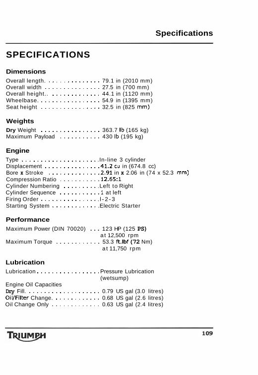
Specifications
SPECIFICATIONS
Dimensions Overall length. . . . . . . . . . . . . . . 79.1 in (2010 mm) Overall width . . . . . . . . . . . . . . . 27.5 in (700 mm) Overall height.. . . . . . . . . . . . . . 44.1 in (1120 mm) Wheelbase. . . . . . . . . . . . . . . . . 54.9 in (1395 mm) Seat height . . . . . . . . . . . . . . . . 32.5 in (825 mm)
Weights Dry Weight . . . . . . . . . . . . . . . . 363.7 Ib (165 kg) Maximum Payload . . . . . . . . . . . 430 Ib (195 kg)
Engine Type . . . . . . . . . . . . . . . . . . . . .In-line 3 cylinder Displacement . . . . . . . . . . . . . . .41.2 cu in (674.8 cc) Bore x Stroke . . . . . . . . . . . . . .2.91 in x 2.06 in (74 x 52.3 mm) Compression Ratio . . . . . . . . . . .12.65:1 Cylinder Numbering . . . . . . . . . .Left to Right Cylinder Sequence . . . . . . . . . . .1 at left Firing Order . . . . . . . . . . . . . . . . l - 2-3 Starting System . . . . . . . . . . . . .Electric Starter
Performance Maximum Power (DIN 70020) . . . 123 HP (125 PS)
a t 12,500 rpm Maximum Torque . . . . . . . . . . . . 53.3 ft.lbf (72 Nm)
a t 11,750 rpm
Lubrication Lubrication . . . . . . . . . . . . . . . . . Pressure Lubrication
(wetsump) Engine Oil Capacities Dry Fill. . . . . . . . . . . . . . . . . . . . 0.79 US gal (3.0 litres) OilIFilter Change. . . . . . . . . . . . . 0.68 US gal (2.6 litres) Oil Change Only . . . . . . . . . . . . . 0.63 US gal (2.4 litres)
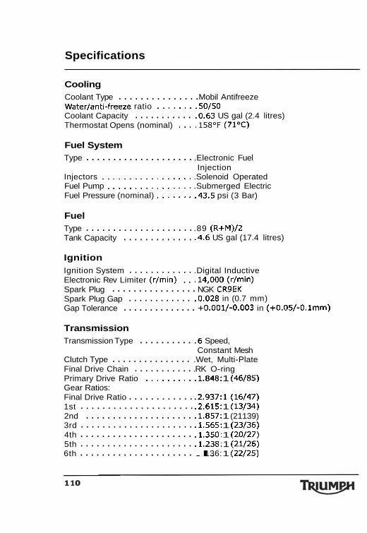
Specifications
Cooling . . . . . . . . . . . . . . . Coolant Type Mobil Antifreeze
Waterlanti-freeze ratio . . . . . . . .50/50 . . . . . . . . . . . Coolant Capacity .0.63 US gal (2.4 litres)
Thermostat Opens (nominal) . . . .158OF (71%)
Fuel System . . . . . . . . . . . . . . . . . . . . Type .Electronic Fuel
Injection Injectors . . . . . . . . . . . . . . . . . .Solenoid Operated Fuel Pump . . . . . . . . . . . . . . . . .Submerged Electric Fuel Pressure (nominal) . . . . . . . .43.5 psi (3 Bar)
Fuel . . . . . . . . . . . . . . . . . . . . Type .89 (R+M)/2
. . . . . . . . . . . . . Tank Capacity .4.6 US gal (17.4 litres)
Ignition . . . . . . . . . . . . Ignition System .Digital Inductive
. . Electronic Rev Limiter (r/min) .14,000 (rlmin) . . . . . . . . . . . . . . . . Spark Plug NGK CR9EK
. . . . . . . . . . . . Spark Plug Gap .0.028 in (0.7 mm) . . . . . . . . . . . . . . Gap Tolerance +0.001/-0.003 in (+0.05/-0.lmm)
Transmission . . . . . . . . . . Transmission Type .6 Speed,
Constant Mesh . . . . . . . . . . . . . . . Clutch Type .Wet, Multi-Plate
. . . . . . . . . . . Final Drive Chain .RK O-ring Primary Drive Ratio . . . . . . . . . .1.848: 1 (46185) Gear Ratios:
. . . . . . . . . . . . Final Drive Ratio .2.937:1 (16147) . . . . . . . . . . . . . . . . . . . . . 1st .2.615: 1 (13134) . . . . . . . . . . . . . . . . . . . . 2nd .1.857: 1 (21139)
. . . . . . . . . . . . . . . . . . . . . 3rd .1.565: 1 (23136)
. . . . . . . . . . . . . . . . . . . . . 4th .1.350: 1 (20127)
. . . . . . . . . . . . . . . . . . . . . 5th .1.238: 1 (21126)
. . . . . . . . . . . . . . . . . . . . . 6th .l. 136: 1 (22125)
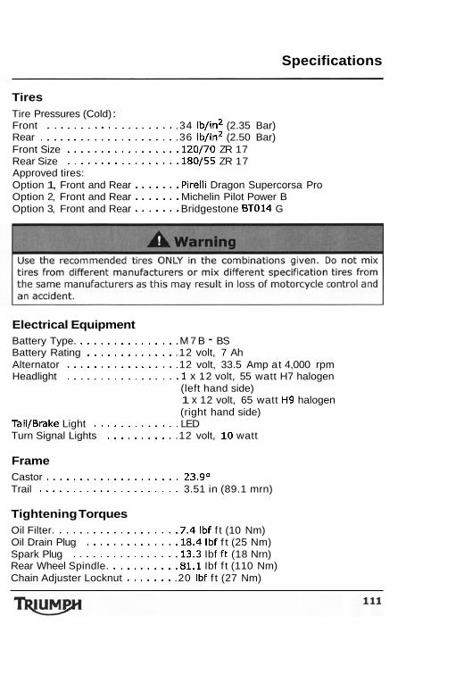
Specifications
Tires Tire Pressures (Cold) : Front . . . . . . . . . . . . . . . . . . . .34 lb/in2 (2.35 Bar) Rear . . . . . . . . . . . . . . . . . . . . .36 lb/in2 (2.50 Bar) Front Size . . . . . . . . . . . . . . . . .120/70 ZR 17 Rear Size . . . . . . . . . . . . . . . . .180/55 ZR 17 Approved tires: Option 1, Front and Rear . . . . . . . Pirelli Dragon Supercorsa Pro Option 2, Front and Rear . . . . . . . Michelin Pilot Power B Option 3, Front and Rear . . . . . . . Bridgestone BT014 G
Electrical Equipment Battery Type. . . . . . . . . . . . . . . . M 7 B - BS Battery Rating . . . . . . . . . . . . . .12 volt, 7 Ah Alternator . . . . . . . . . . . . . . . . .12 volt, 33.5 Amp at 4,000 rpm Headlight . . . . . . . . . . . . . . . . .l x 12 volt, 55 watt H7 halogen
(left hand side) 1 x 12 volt, 65 watt H9 halogen (right hand side)
TailIBrake Light . . . . . . . . . . . . . LED Turn Signal Lights . . . . . . . . . . .12 volt, 10 watt
Frame Castor . . . . . . . . . . . . . . . . . . . . 23.g0 Trail . . . . . . . . . . . . . . . . . . . . . 3.51 in (89.1 mrn)
Tightening Torques Oil Filter. . . . . . . . . . . . . . . . . . .7.4 Ibf f t (10 Nm) Oil Drain Plug . . . . . . . . . . . . . .18.4 Ibf f t (25 Nm) Spark Plug . . . . . . . . . . . . . . . .13.3 Ibf ft (18 Nrn) Rear Wheel Spindle. . . . . . . . . . .81.1 Ibf f t (110 Nm) Chain Adjuster Locknut . . . . . . . .20 Ibf f t (27 Nm)
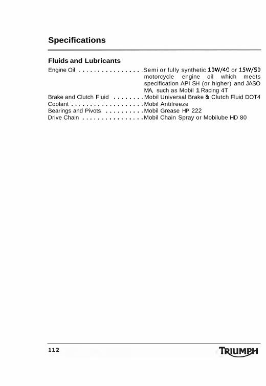
Specifications
Fluids and Lubricants Engine Oil . . . . . . . . . . . . . . . . .Semi or fully synthetic 10W/40 or 15W/50
motorcycle engine oil which meets specification API SH (or higher) and JASO MA, such as Mobil 1 Racing 4T
Brake and Clutch Fluid . . . . . . . . Mobil Universal Brake & Clutch Fluid DOT4 Coolant . . . . . . . . . . . . . . . . . . . Mobil Antifreeze Bearings and Pivots . . . . . . . . . . Mobil Grease HP 222 Drive Chain . . . . . . . . . . . . . . . . Mobil Chain Spray or Mobilube HD 80
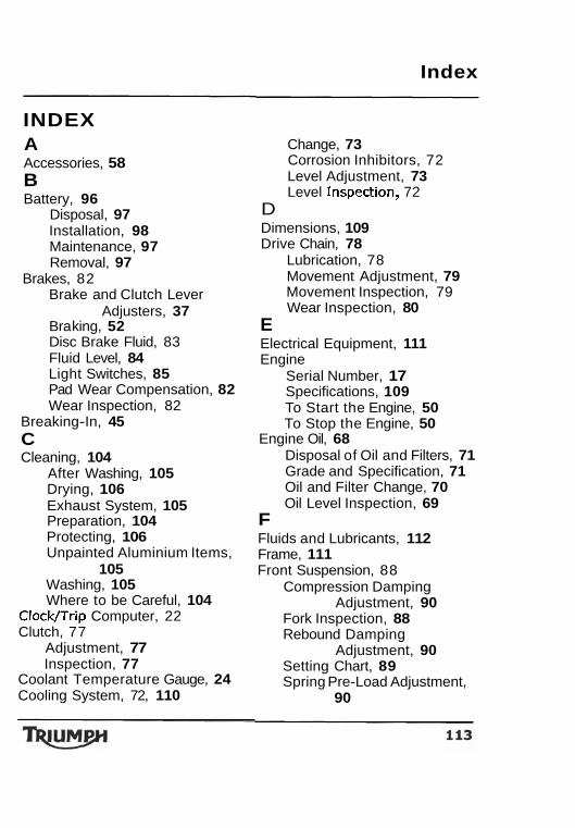
Index
INDEX A Accessories, 58 B Battery, 96
Disposal, 97 Installation, 98 Maintenance, 97 Removal, 97
Brakes, 82 Brake and Clutch Lever
Adjusters, 37 Bra king, 52 Disc Brake Fluid, 83 Fluid Level, 84 Light Switches, 85 Pad Wear Compensation, 82 Wear Inspection, 82
Breaking-In, 45 C Cleaning, 104
After Washing, 105 Drying, 106 Exhaust System, 105 Preparation, 104 Protecting, 106 Unpainted Aluminium Items,
105 Washing, 105 Where to be Careful, 104
Clock/Trip Computer, 22 Clutch, 77
Adjustment, 77 Inspection, 77
Coolant Temperature Gauge, 24 Cooling System, 72, 110
Change, 73 Corrosion Inhibitors, 72 Level Adjustment, 73 Level Inspection, 72
D Dimensions, 109 Drive Chain, 78
Lubrication, 78 Movement Adjustment, 79 Movement Inspection, 79 Wear Inspection, 80
E Electrical Equipment, 11 1 Engine
Serial Number, 17 Specifications, 109 To Start the Engine, 50 To Stop the Engine, 50
Engine Oil, 68 Disposal of Oil and Filters, 71 Grade and Specification, 71 Oil and Filter Change, 70 Oil Level Inspection, 69
F Fluids and Lubricants, 112 Frame, 111 Front Suspension, 88
Compression Damping Adjustment, 90
Fork Inspection, 88 Rebound Damping
Adjustment, 90 Setting Chart, 89 Spring Pre-Load Adjustment,
90

Index Foreword
Fuel, 110 Fuel Requirement, 40
Filling the Fuel Tank, 42 Fuel Grade, 40 Fuel Tank Cap, 42
Fuel System, 110 Fuse Box, 98 G Gear Change Lights, 28 Gears
Changing Gears, 52 H Handlebar Switches
Left, 39 Right, 38
Headlights, 100 Adjustment, 100 Bulb Replacement, 101 Position Lamp, 102
I Ignition, 110
Key, 36 Switch/Steering Lock, 36
Instrument Panel Layout, 20 L Lap Timer, 24 License Plate Light, 103 Lubrication, 109 0 Odometer/Trip Meter, 21 P Performance, 109 R Rear Light, 103 Rear Seat, 44 Rider's Seat, 44
S Safety, 5
Daily Checks, 46 Fuel and Exhaust Fumes, 5 Handlebars and Footrests, 11 Helmet and Clothing, 6 Maintenance/Equipment, 8 Motorcycle, 5 Parking, 7 Parts and Accessories, 7 Riding, 9
Seat Lock, 44 Speedometer, 21 Stand, 43
Side Stand, 43 Steering/Wheel Bearings, 86
Inspection, 86 Storage
Preparation after Storage, 107
Preparation for Storage, 107 T Tachometer, 21 Throttle Control, 74 Tightening Torques, 111 Tires, 92, 11 1
Inflation Pressures, 92 Minimum Tread Depth, 93 Replacement, 94
Tool Kit, 43 Transmission, 11 0 v Vehicle Identification Number, 17 W Warning Lights, 34 Warnings
Owner's Handbook Thank you for choosing a Triumph motorcycle. This motorcycle is the product of Triumph's use of proven engineering, exhaustive testing, and continuous striving for superior reliability, safety and performance. Please read this owner's handbook before riding in order to become thoroughly familiar with the correct operation of your motorcycle's controls, its features, capabilities and limitations. This manual includes safe riding tips, but does not contain all the techniques and skills necessary to ride a motorcycle safely. Triumph strongly recommends that all riders undertake a safety course approved by the Motorcycle Safety Foundation to ensure safe operation of this motorcycle. Information about the nearest Motorcycle Safety Foundation course to you can be obtained by calling the following nationwide toll free number: 800- 447-4700, or by writing to the Motorcycle Safety Foundation at: 2, Jenner Street, Irvine, California 92718. To ensure a long and trouble free life for your motorcycle, maintenance should be carried out as described in this manual by an authorized Triumph dealer.
A warning This owner's handbook. and all other instructions that arb supplied with your motorcycle, should be considered a permanent part of your motorcycle and should remain with it even if your motorcycle is subsequently sold. All riders must read this owner's handbook and all other instructions which are supplied with your motorcycle, before riding, in order to become thoroughly familiar with the correct operation of your motorcycle's controls, its features, capabilities and limitations. Do not lend your motorcycle to others as riding when not familiar with your motorcycle's controls, features, capabilities and limitations can lead to an accident.
Index
Warning Label Locations, 12 Warning Labels, 2 Warnings, Cautions and
Notes, 1 Weights, 109 Windscreen Cleaning, 85