J$ A..:l~ - ECED Mansoura · 1-a) Draw phasor diagram for a cylindrical rotor alternator with...
4
Mansoura University Faculty of Engineering 2 nd - Year Exam. Electrical Eng. Dept. Time: 1.5 Hours "~'J~\ ~!<2;j 2012 ~JU\ -~~ (JJ'J\ s:..»ll) 44~\ ~'J'Jl ..;1#-1" ANSWER ALL THE FOLLOWING QUESTIONS: :J 9'J1 J\'~ :~ L..&~ JSJ ~)!.::JI (.)-QlyJl ~ 01.S-, lSjljiJl ~ ~-' b=-. 11" )lSjlji~.)'Lfj Ub1y l!=- .ll"..Jl ~ )WI (.)-QlyJl l>~ v (Volt) : 230 228.8 227.5 225.5 224 222 220 215.5 215 I (Ampere): 0 25 50 75 100 125 150 200 250 209.5 2e .ll"..Jl ~ )WI (.)-QlyJl ~ v (Volt) : 240 237.5 235 232 228.5 224.5 220 218 208.5 I (Ampere): 0 25 50 75 100 125 150 175 200 : ~I 1") 100 ~ JSJ ~I ~-'~-" 1"-,1 0.03 ~ JSJ ~I ~-'~ 01.SI~t! ,~I 250..Jk> ~I ~I 01.$ I~I .llyo J$ A..:l~ lS~1 .)\;ill IjS-,~..):JI ~I (I) (J-,-* ~ ~41 0-'~) , 21"~"..Jl ~1.llI (.)-QlyJl ~ (y) (J-,-* ~ ~l:;..1 u-'~) . 21" ~yJl.)lfj J5.l~liA!l\-, wl.;JY ~I ~~.) ~ (<;:) :~WI JI.J...JI 220 o*.)~ 0-0 ~~I lS~ .~yJl~..)A ~ 4--ojc. y....u~ ~I-, ,~jS...)A ~.J:1~ t.jjlji ~~ ~~} ~ ~I ~-,ti.JI ~ L.o. ~~ to.)-,::. 1000 ~~ .... u~ ~~ ,~150 o)~ t.J'Lfj h~-, ,wl~ '1"-,\ 110 ~ J4wJ1~-'~-' I"Ji 0.1 ~ ~I ~-'~ .~~ /0.)-'::' 800.)) ~yJI ~ 15 V, lOA, 85 W. ·~I~I~ " . Ul.JI * 01ft) .y.li.a 0.8 o.)~ J,..Gt..o,ljc..Jf:lAi 16 o)~)fo. ~ t.j~~,ljc. tj..J-iLilIWAll * (I) .wl..,9 200 ..Jk> ~I~)'I .~I~J,..~~ (y) . ~I 1~ ~ o~lli..ll~ (w) .0AYI 0 j::,3 J,..Gt..o ,ljc. ~1 0~liS.l144 (w) Good Luck With My Best Wishes PROF.Dr. A.R.A.Amin .r " -c, " / 1 '. I
Transcript of J$ A..:l~ - ECED Mansoura · 1-a) Draw phasor diagram for a cylindrical rotor alternator with...

Mansoura UniversityFaculty of Engineering 2nd
- Year Exam.Electrical Eng. Dept. Time: 1.5 Hours
"~'J~\ ~!<2;j 2012 ~JU\ -~~ (JJ'J\ s:..»ll) 44~\ ~'J'Jl..;1#-1"ANSWER ALL THE FOLLOWING QUESTIONS:
: J 9'J1 J\'~: ~ L..&~ JSJ ~)!.::JI (.)-QlyJl ~ 01.S-,lSjljiJl ~ ~-' b=-. 11" )lSjlji~.)'Lfj Ub1y
l!=- .ll"..Jl ~ )WI (.)-QlyJl l>~
v (Volt) : 230 228.8 227.5 225.5 224 222 220 215.5 215I (Ampere): 0 25 50 75 100 125 150 200 250 209.5
2e .ll"..Jl ~ )WI (.)-QlyJl ~
v (Volt) : 240 237.5 235 232 228.5 224.5 220 218 208.5I (Ampere): 0 25 50 75 100 125 150 175 200
: ~I 1") 100 ~ JSJ ~I ~-'~-" 1"-,1 0.03 ~ JSJ ~I ~-'~ 01.SI~t!,~I 250..Jk> ~I ~I 01.$ I~I.llyo J$ A..:l~ lS~1.)\;ill IjS-,~..):JI ~I (I)
(J-,-* ~ ~41 0-'~) , 21"~"..Jl ~1.llI (.)-QlyJl ~ (y)(J-,-* ~ ~l:;..1 u-'~) . 21"~yJl.)lfj J5.l~liA!l\-, wl.;JY ~I ~~.) ~ (<;:)
:~WI JI.J...JI220 o*.)~ 0-0 ~~I lS~ .~yJl~..)A ~ 4--ojc.y....u~ ~I-, ,~jS...)A~.J:1~ t.jjlji ~~
~~} ~ ~I ~-,ti.JI ~ L.o. ~~ to.)-,::. 1000 ~~ ....u~ ~~ ,~150 o)~ t.J'Lfjh~-, ,wl~'1"-,\ 110 ~ J4wJ1~-'~-' I"Ji 0.1 ~ ~I ~-'~ .~~ /0.)-'::'800.)) ~yJI ~
15 V, lOA, 85 W.·~I~I~" .
Ul.JI *01ft) .y.li.a 0.8 o.)~ J,..Gt..o,ljc..Jf:lAi 16 o)~)fo. ~ t.j~~,ljc. tj..J-iLilIWAll * (I).wl..,9200 ..Jk> ~I~)'I.~I~J,..~~ (y)
. ~I 1~ ~ o~lli..ll~ (w).0AYI 0j::,3 J,..Gt..o,ljc. ~1 0~liS.l144 (w)
Good Luck With My Best WishesPROF.Dr. A.R.A.Amin
.r " -c, "
/ 1'. I
Mansoura University.Faculty Of Engineering.Electrical Engineering Dept.
Electric MachineTime allowed: 3 Hours3/6/2012
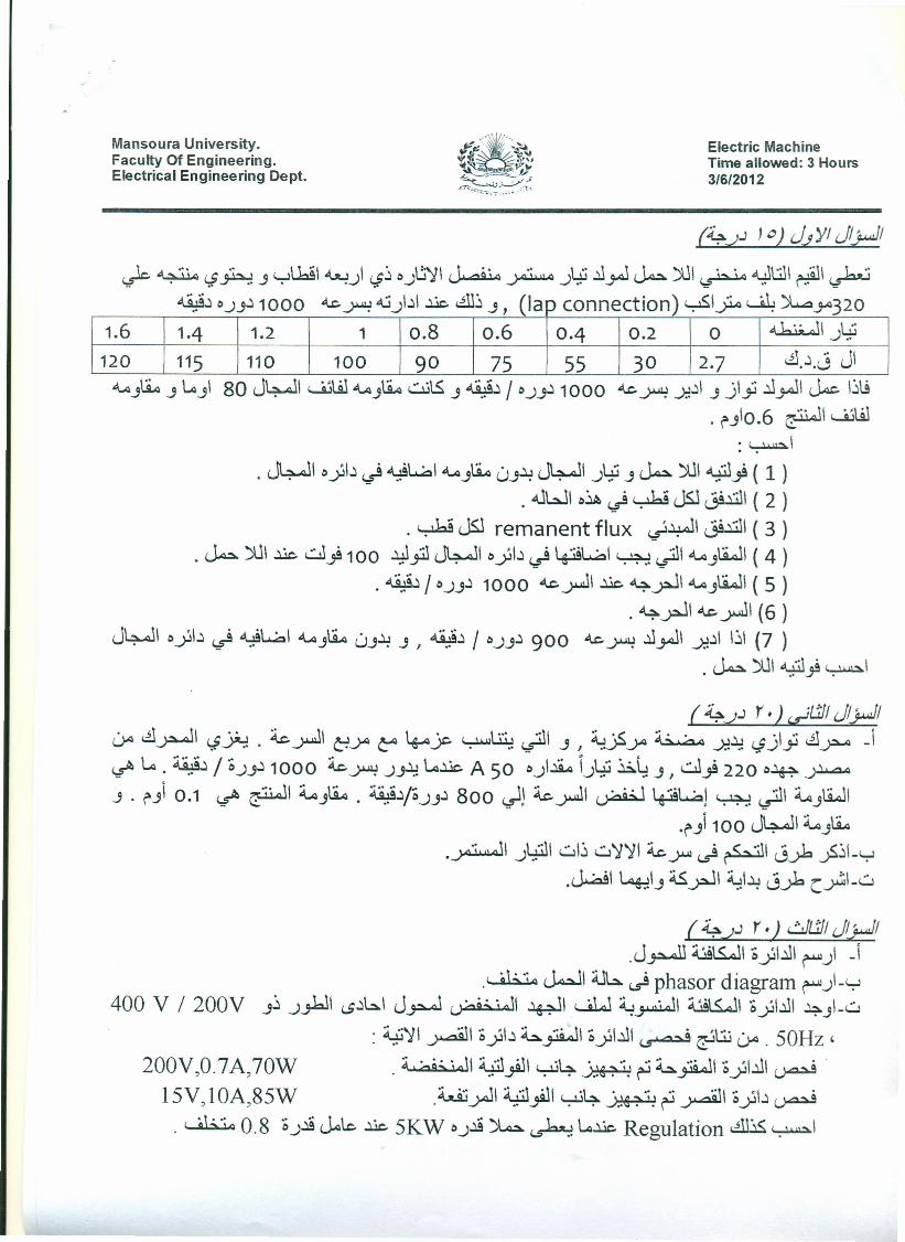
(4").J 'c) JJ Y/ J;y.JI1- ~ .' wt..b!1~ 1 ~0 ~~I ~ .' tii .ll.."J~ )1JI . , .wlti.ll- ·~'I~r..r-, <j~.J , ,.J <j .J ~ .J" ~ ~ r::-_
~~ 0.J.J~1000 4..c.~ .u)~1 ..l£ ~~.J, (lap connection) ~I? ~ ~ya320"
1.6 1·4 1.2 1 0.8 0.6 0·4 0.2 0 ~I tii.J~
120 115 110 100 90 75 55 30 2·7 ~.~.J JI~.JLi.a.J~.JI 80 J4--JI ~\.il ~.JLi.aut5..J ~~ / 0.J.J~1000 4..c.~ .J:l~I.Jjlji ~.."JI~ I~lj
1 6 _';~JI~W. f'.Jo. e:..--"• WJ..u::I.I. ,
. J4--JI oyl~ ~ .y9hal ~.JLi.a0.J~ J4--JI .JYJ.J~)1JI.y:il..,g ( 1). .uwl o~ ~ ~ JS1J9.l.il1( 2 )
. ~ JS1 remanent flux ~~I J9.l.il1( 3 ). ~)1JI ..l£ ..::.J..,g100~ji1 J4..JI oyl~ ~ 4-J9hal~ ~I ~,)\iJI ( 4 )
. ~~ / 0.J.J~1000 4..c.~I ..l£ ~yJI ~.J\iJI ( 5 ). ~yJI 4..c.~1 (6 )
J4--JI oyl~ ~ .y9hal ~.JLi.a0,)~.J I ~~ / 0.J.J~900 4..c.~ ~.."JI .J:l~1I~I (7 ).~)1JI~)~1
( 4,,).J r.) ~llJ/ J;y.JI0-a ~~\ <jJi.:. . ~..;.uJI CjjA ca 4--aJc~~ ~I .s I ~jSjA ~ .J:l~ <jjlji ~~ J~ ~. ~~ / 0.J.J~1000 ~~ .J.J~l.c..l£A 50 o)~ \.JYJ~~.J I ..::.J..,g220 o~.J~
.J . f'.Ji0.1 ~ ~\ ~.JLi.a. ~4o.J.J~ 800 ~J ~~I ~ '+i9ha} ~ ~I ~.JtiJI.f') 100 J4..JI ~.J~
.~\ .J4il\ w\~ w~~\ ~.J-I-Il ~ r-W1 J...rb.fi~I-y.~I 4::1,)asyJ\ ~\~ J...rbC~\-w
( 4,,).J r.) r.!JllJ/ J;y.JI.J~ ~1&J\ oYI.ll\~) -i
.' 9"'4 ~I ~6. ~ phasor diagram ~)-'-:-l400 V / 200V .J~.J.#I (.S~6.1J~ woo';" iJI ~I wlJ ~~I ~1&JI oyl.lll 4.JI-w
. 4.ii~\ . _'.:1\ 0 'I~~ .-:;'JI 0 '\~I. ~ ....~ '\.:ij' 50H,. ~ ~ y ~ y ~~ UA. z200V 0 7A 70W :1 \ 00';" iJ\ :i.iil.;.'1I....,lj6.' ,',' ~ .-:;'-'I 0 'I~\ ..,. , . " ~ , ,~~ ~ y ~
15V lOA 85W ~ .JI :i.iil·;.'1wj6.' ~ ~ . -'.:'10 'I~ ., , . ~ ,• .Y-J , ,~~~ y ~
. ' 9"';4 0.8 o.J~~b ..l£ 5KW o.J~)b ~~..l£ Regulation ~~ ~I
Mansoura University.Faculty Of Engineering.Electrical Engineering Dept.
Electric MachineTime allowed: 3 Hours3/6/2012
Final Term ExamFodd Grad Electronic Department
Answer All Question.
First Question: (15 Marks)1-a) Draw phasor diagram for a cylindrical rotor alternator with armature
current lagging, leading, and unity pf. discusses the various parametersinvolved in it. Explain how the diagram can be applied a synchronousmotor.
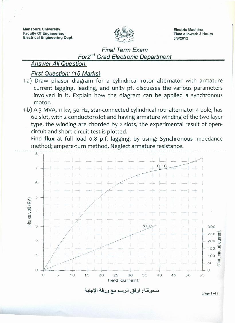
1-b) A 3 MVA, 11kv, 50 Hz, star-connected cylindrical rotr alternator 4 pole, has60 slot, with 2 conductor/slot and having armature winding of the two layertype, the winding are chorded by 2 slots, the experimental result of open-circuit and short circuit test is plotted.Find flux at full load 0.8 p.f. lagging, by using: Synchronous impedancemethod; ampere-turn method. Neglect armature resistance.
8 T7 1-~3 1-
----- 5J-
> I~r
0 4 +~><l.)Cl)ro-C.0...
3
o
T
300
[250 i~ 200 ~
~150-32
100 -(3t
50 ~eno
5 10 20 25 30 35field current
15 40 45 50 55
Page 10f2
Second Question: (20 Marks)2-a) i- from test of synchronous machine, find equivalent circuit.
ii- from test of induction machine, find equivalent circuit.2-b) Explain the operation principle and draw the power flow of a 3-phase
induction machine at the following operation cases:i- Starting period, ii- No-Load condition,iii- Running at rated load with slip (s) iv- Running at negative slip
then, prove that: Pg: PCU2 : Pm = 1:s : 1-S
Third Question: (20 Marks)3-a) Explain why single phase induction motors are not self starting? State and
compare between the various type of them?3-b) Explain (with help of net diagrams) the starting method adopted for:
i-Three-phase induction motor (squirrel-cage and slip ring).ii-Three-phase synchronous machine.
3-c) A 415 V, 50 Hz, 6 pole, delta connected three phase induction motorconsumes 70 Watt with line current of 112.5A and runs at slip 3 %. If thestator iron losses is 3 KW, windage and friction losses 2 KW and statorresistance 0.1O/ph, and rotor reactance 1O/ph. Calculate:a- Rotor cupper loss; b- Mechanical power;c- Developed shaft torque; d- maximum torque;
d- Efficiency
With my Beast Wishes
Page 2 of2