
Generator Alternator
24
Installation and maintenance Réf. 2950 - 4.33/d - 09.01 2000 / 3000 SERIES ALTERNATORS 347 124 198 37 4 15 30 33 323 324 322 28 PART NUMBER : 277- 805
-
Upload
salmanejaz -
Category
Documents
-
view
131 -
download
14
Transcript of Generator Alternator
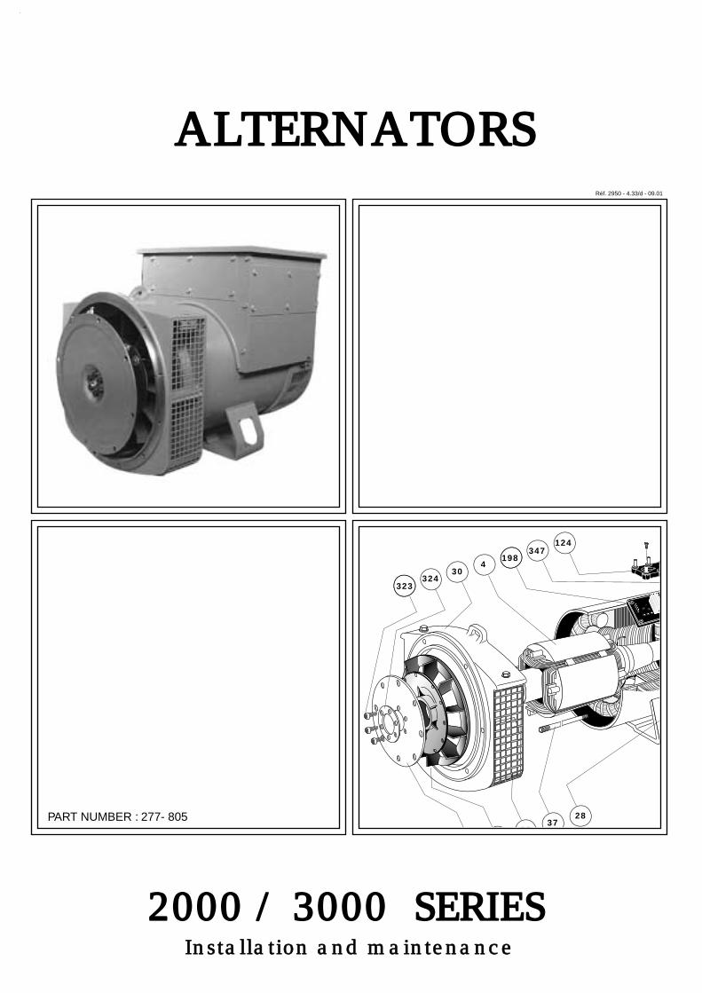
Installation and maintenance
Réf. 2950 - 4.33/d - 09.01
2000 / 3000 SERIES
ALTERNATORS
347124
198
37
4
15
30
33
323324
322
28PART NUMBER : 277- 805
This manual applies to the alternator mounted on the genset.
The latest addition to a whole new generation of products, this range benefits from the expe-rience of one of the largest manufacturers in the world, using advanced technology and incorpo-
rating strict quality control.
We would like to draw your attention to the contents of this maintenance manual. By followingcertain important instructions during installation, use and servicing of your alternator, you can
look forward to many years of trouble-free operation.
2
ALTERNATOR maintenance 2000 / 3000 Series 4 Pole
1 - RECEIPT
1.1 - Standards and safety measures ......... 3 1.2 - Checks ............................................... 31.3 - Identification ........................................ 31.4 - Storage ............................................... 3
2 - TECHNICAL CHARACTERISTICS
2.1 - Electrical characteristics ..................... 42.2 - Mechanical characteristics .................. 42.3 - SHUNT field excitation system ............ 5
2.4 - AREP field excitation system .............. 62.5 - SHUNT + PMG .................................... 8
3 - INSTALLATION - COMMISSIONING
3.1 - Assembly ............................................ 93.2 - Inspection prior to first use ................. 93.3 - Electrical diagram ................................ 103.4 - Commissioning .................................... 123.5 - Setting up ........................................... 13
CONTENTS
4 - SERVICING - MAINTENANCE4.1 - Safety measures ................................ 154.2 - Regular maintenance ......................... 154.3 - Fault detection .................................... 154.4 - Mechanical defects .............................. 164.5 - Electrical faults .................................... 164.6 - Dismantling, reassembly ...................... 184.7 - Installation / maintenance of PMG ....... 204.8 - Characteristics table ........................... 20
5 - SPARE PARTS 5.1 - First maintenance parts ....................... 215.2 - Technical support service .................... 215.3 - Exploded view, parts list ..................... 22
CONTENTS
3
ALTERNATOR maintenance 2000 / 3000 Series 4 Pole
1 - RECEIPT
1.1 - Standards and Safety measuresOur alternators comply with most international standardsand are compatible with:- the recommendations of the International Electro
technical Commission IEC 34-1, (EN 60034).- the recommendations of the International Standards
Organisation ISO 8528.- the European Community directive on Electromagnetic
Compatibility (EMC) 89/336/EEC.- the European Community directives 73/23/EEC and93/68/EEC (Low Voltage Directive).
They are CE marked with regard to the LVD (LowVoltage Directive) in their role as a machine component.A declaration of incorporation can be supplied on request.Before using your generator for the first time, read withcare the contents of this installation and maintenancemanual, supplied with the machine. All operationsperformed on the generator should be undertaken byqualified personnel with specialist training in the commis-sioning, servicing and maintenance of electrical and me-chanical machinery. This maintenance manual should beretained for the whole of the machine's life and be han-ded over with the contractual file.The various operations described in this manual areaccompanied by recommendations or symbols to alert theuser to the risk of accidents. It is vital that you understandand take notice of the different safety symbols opposite.
Safety symbol for an operation capable of da-maging or destroying the machine or surroun-ding equipment.
Safety symbol for general danger to personnel.
Safety symbol for electrical danger to personnel.
1.2 - ChecksOn receipt of your alternator, check that it has not sufferedany damage in transit. If there are obvious signs of knocks, contact the trans-porter (you may be able to claim on their insurance) andafter a visual check, turn the machine by hand (if twinbearing) to detect any malfunction.
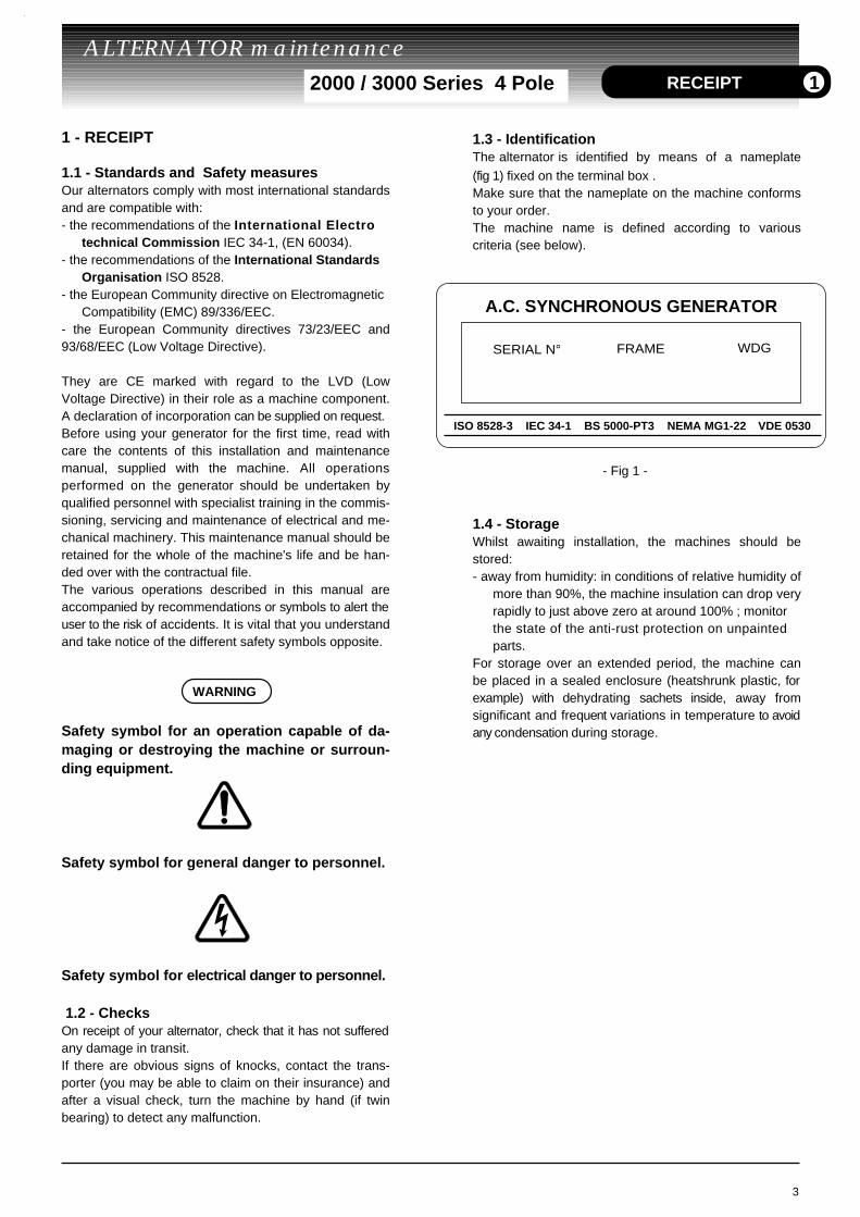
1.3 - IdentificationThe alternator is identified by means of a nameplate(fig 1) fixed on the terminal box .Make sure that the nameplate on the machine conformsto your order.The machine name is defined according to variouscriteria (see below).
- Fig 1 -
1.4 - StorageWhilst awaiting installation, the machines should bestored:- away from humidity: in conditions of relative humidity of
more than 90%, the machine insulation can drop veryrapidly to just above zero at around 100% ; monitor the state of the anti-rust protection on unpainted parts.
For storage over an extended period, the machine canbe placed in a sealed enclosure (heatshrunk plastic, forexample) with dehydrating sachets inside, away fromsignificant and frequent variations in temperature to avoidany condensation during storage.
WARNING
RECEIPT 1
A.C. SYNCHRONOUS GENERATOR
SERIAL N° FRAME WDG
ISO 8528-3 IEC 34-1 BS 5000-PT3 NEMA MG1-22 VDE 0530
2 - TECHNICAL CHARACTERISTICS
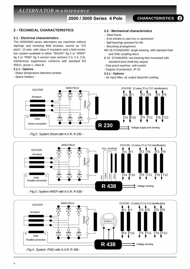
2.1 - Electrical characteristicsThe 2000/3000 series alternators are machines withoutsliprings and revolving field brushes, wound as "2/3pitch"; 12-wire, with class H insulation and a field excita-tion system available in either "SHUNT" fig 2 or "AREP"fig 3 or "PMG" fig 4 version (see sections 2.3, 2.4, 2.5).Interference suppression conforms with standard EN55011, group 1, class B. 2.1.1 - Options- Stator temperature detection probes- Space heaters
4
ALTERNATOR maintenance 2000 / 3000 Series 4 Pole
2.2 - Mechanical characteristics- Steel frame- End shields in cast iron or aluminium- Ball bearings greased for life- Mounting arrangement MD 35 STANDARD: single bearing, with standard feet
and SAE coupling discsB 34 STANDARD: two bearing feet mounteed with
standard bare shaft key wayed- Drip-proof machine, self-cooled- Degree of protection: IP 23 2.2.1 - Options- Air input filter, air output labyrinth cowling
T1 T2 T3
T4 T5 T6
T7 T8 T9
T10 T11 T12
R 230
5+ 6 -
- Fig 2 : System Shunt with A.V.R. R 230 -
Var
isto
r
Field
STATOR : 12 wires (T1 to T12 identification)EXCITER
Armature
Series connection
MAIN FIELD
Voltage supply and sensing
T1 T2 T3
T4 T5 T6
Var
isto
r
5+ 6-
T7 T8 T9
T10 T11 T12
R 438
Aux. windings
Gre
en
Yel
low
Red Bla
ck
Field
STATOR : 12 wires (T1 to T12 identification)
Voltage sensing
EXCITER
Armature
MAIN FIELD
- Fig 3 : System AREP with A.V.R. R 438 -
Parallel connection
CHARACTERISTICS 2
T1 T2 T3
T4 T5 T6
Var
isto
r
5+ 6-
T7 T8 T9
T10 T11 T12
R 438
Field
STATOR : 12 wires (T1 to T12 identification)
Voltage sensing
EXCITER
Armature
MAIN FIELD
PMG
- Fig 4 : System PMG with A.V.R. R 438 -
Parallel connection
5
ALTERNATOR maintenance 2000 / 3000 Series 4 Pole CHARACTERISTICS 2
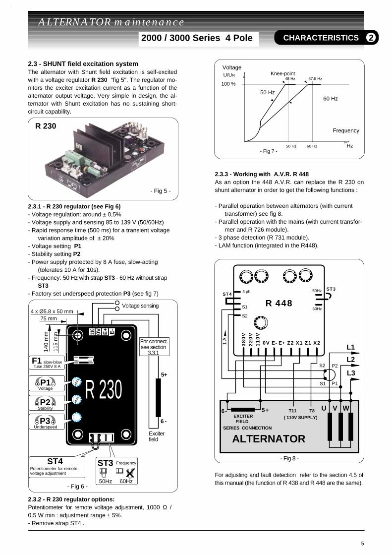
2.3 - SHUNT field excitation system The alternator with Shunt field excitation is self-excitedwith a voltage regulator R 230 "fig 5". The regulator mo-nitors the exciter excitation current as a function of thealternator output voltage. Very simple in design, the al-ternator with Shunt excitation has no sustaining short-circuit capability.
2.3.1 - R 230 regulator (see Fig 6) - Voltage regulation: around ± 0,5% - Voltage supply and sensing 85 to 139 V (50/60Hz)- Rapid response time (500 ms) for a transient voltage
variation amplitude of ± 20%- Voltage setting P1- Stability setting P2- Power supply protected by 8 A fuse, slow-acting
(tolerates 10 A for 10s).- Frequency: 50 Hz with strap ST3 - 60 Hz without strap
ST3- Factory set underspeed protection P3 (see fig 7)
2.3.2 - R 230 regulator options: Potentiometer for remote voltage adjustment, 1000 Ω / 0.5 W min : adjustment range ± 5%.- Remove strap ST4 .
2.3.3 - Working with A.V.R. R 448 As an option the 448 A.V.R. can replace the R 230 onshunt alternator in order to get the following functions :
- Parallel operation between alternators (with current transformer) see fig 8.
- Parallel operation with the mains (with current transfor-mer and R 726 module).
- 3 phase detection (R 731 module).- LAM function (integrated in the R448).
For adjusting and fault detection refer to the section 4.5 ofthis manual (the function of R 438 and R 448 are the same).
Exciterfield
Voltage sensing
5+
6 -
F1
Underspeed
Stability
slow-blow fuse 250V 8 A
Voltage
Potentiometer for remotevoltage adjustment
ST4
75 mm
140
mm
115
mm
4 x Ø5.8 x 50 mm
E+ E-
0V110
P3
P1
P2
ST3 Frequency
50Hz 60Hz
R 230
- Fig 6 -
For connect.see section
3.3.1
VoltageKnee-pointU/UN
100 %
50 Hz 60 Hz
Frequency
Hz
50 Hz
48 Hz 57.5 Hz
60 Hz
- Fig 7 -
- Fig 5 -
R 230
R 448
0V E- E+ Z2 X1 Z1 X2
5+ 6-
S1
S2
ST450Hz
60Hz
T11 T8
ST3
3 ph
P1
P2
S1
S2
- Fig 8 -
U
L1
L3
V W
L2
38
0V
22
0V
11
0V
1 A
ALTERNATOR
EXCITER FIELD
( 110V SUPPLY)
SERIES CONNECTION

2.4 - AREP field excitation system With AREP excitation, the electronic A.V.R. R 438 (fig 9)is powered by two auxiliary windings which are indepen-dent of the voltage detection circuit. The first winding(X1,X2) has a voltage in proportion with the output voltage ofthe alternator (Shunt characteristic), the second (Z1,Z2)has a voltage in proportion with the stator current (com-pound characteristic: Booster effect). The power supplyvoltage is rectified and filtered before being used by theregulator monitoring transistor. This principle ensuresthat regulation is not affected by distortions generated bythe load.
2.4.1 - R 438 regulator (fig 10)
ST9 MUST BE CLOSED FOR AREP EXCITATION
- short-circuit current = 3 x IN for 10 seconds- standard power supply; 2 auxiliary windings - shunt supply; max 48V - 50/60 Hz- rated overload current: 8A - 10s- electronic protection (overload, short-circuit opening on
voltage detection): excitation ceiling current for 10 seconds then return to approx. 1AThe alternator must be stopped (or the power switched off) in order to reset the protection.
- Fuse F1 on input side (X1, X2)- Fuse F2 on output side (E+, E-)- voltage detection: 5 VA isolated via transformer
0-110 V terminals = 95 to 140 V0-220 V terminals = 170 to 260 V0-380 V terminals = 340 to 520 V
- voltage regulation ±1%- rapid or normal response time via strap ST2- voltage adjustment via potentiometer P2 other voltages via step down transformer- current detection: (parallel operation): C.T. 2.5 VA cl1,
secondary 1A (Option)- quadrature droop adjustment via potentiometer P1- underspeed protection (U/f) and LAM: frequency thres-
hold adjustable via potentiometer P4
- max. excitation current adjustment via P5: 4.5 to 10A- 50/60 Hz selection via strap ST3
2.4.2 - R 438 A.V.R. options - Current transformer for parallel operation- Remote voltage adjustment potentiometer :
470 Ω, 0.5 W min: adjustment range ± 5% (range limited via internal voltage potentiometer P2).
Remove ST4 to connect the potentiometer. A 1 k Ω potentiometer can also be used to extend the adjust-ment range.
- R 731 : detection of 3-phase voltage 200 to 500 V, compatible with parallel operation. Cut ST1 to connect the module; set the voltage via the module potentiometer. (The previous version moduleis not compatible with parallel operation).
- R 726 module: 3 functions . P.F. ϕ regulation (2F) and voltage matching prior to pa
ralleling with the mains (3 F).
6
ALTERNATOR maintenance 2000 / 3000 Series 4 Pole
Aux. windings
- Fig 10 -
YellowGreenBlackRed
Exciter field5+ 6 -
ST3 50Hz 60Hz
125 mm
140
mm
115
mm
4 x Ø5.8 x100
X2
X1Z2E+E-0V110220380
Z1
L2(V)
L3 (W)
340-520V
170-260V
95-140V
R438
Excitationceiling
Frequency
Underspeed
Stability
P5
P2
P4
P3
Voltage
F1/F2
ST2ST5
normal rapid
R731T.I.
ST4
Option
Option
Option S1 S2
P1
Response time
With LAM W/O LAM
Fast-blow fuse 250V 8 A
Quadrature droop
SHUNT AREP
PMG
External potentiometerfor voltage adjustment
3 phase detection
ST1 ST9Single phasedetection
For connectionsee section 3.3.1
CHARACTERISTICS 2
- Fig 9 -
R 438
WARNING
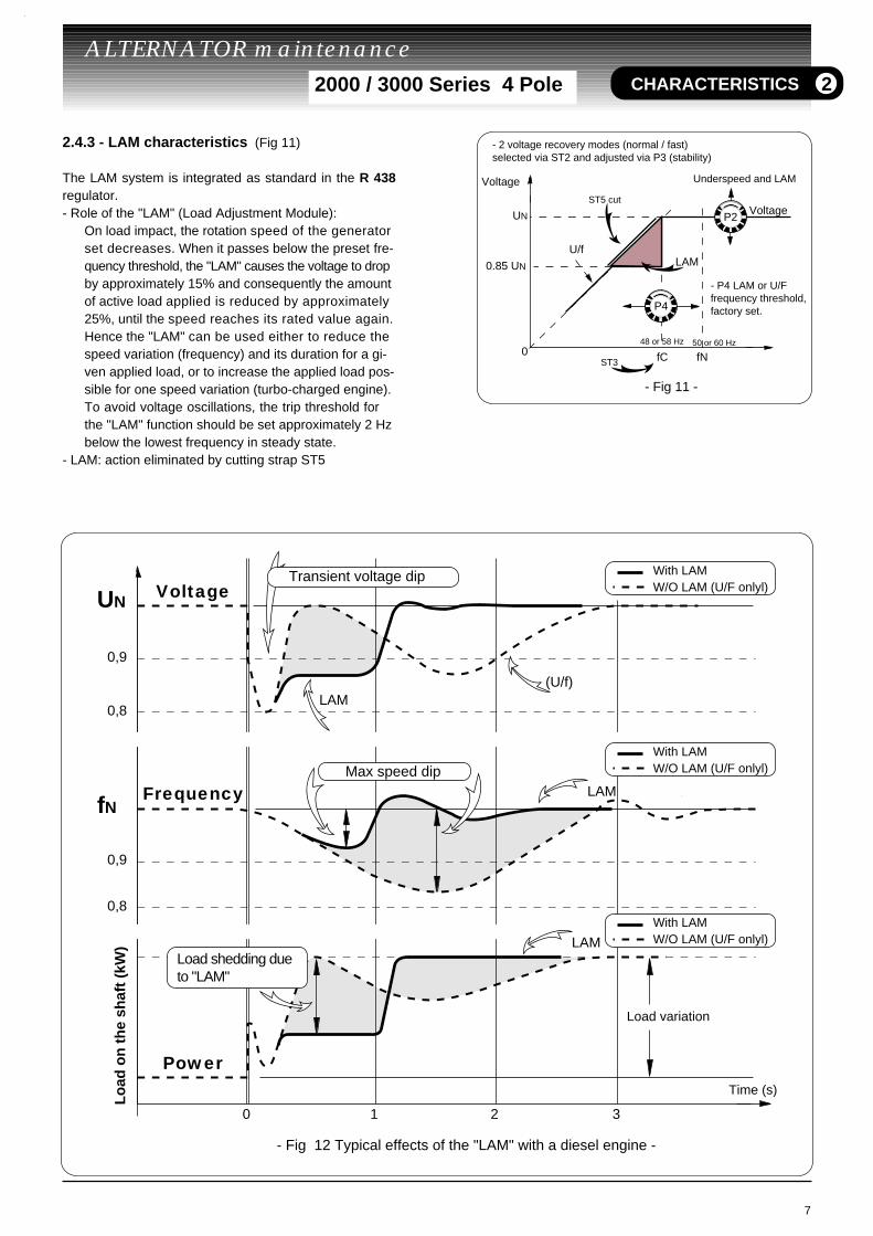
2.4.3 - LAM characteristics (Fig 11)
The LAM system is integrated as standard in the R 438regulator.- Role of the "LAM" (Load Adjustment Module):
On load impact, the rotation speed of the generator set decreases. When it passes below the preset fre-quency threshold, the "LAM" causes the voltage to drop by approximately 15% and consequently the amount of active load applied is reduced by approximately 25%, until the speed reaches its rated value again.Hence the "LAM" can be used either to reduce the speed variation (frequency) and its duration for a gi-ven applied load, or to increase the applied load pos-sible for one speed variation (turbo-charged engine).To avoid voltage oscillations, the trip threshold for
the "LAM" function should be set approximately 2 Hz below the lowest frequency in steady state.
- LAM: action eliminated by cutting strap ST5
7
ALTERNATOR maintenance 2000 / 3000 Series 4 Pole
LAM
UN
048 or 58 Hz
0.85 UN
Voltage
U/f
50 or 60 Hz
fC fN
VoltageST5 cut
ST3
- 2 voltage recovery modes (normal / fast) selected via ST2 and adjusted via P3 (stability)
P2
P4
Underspeed and LAM
- P4 LAM or U/F frequency threshold,factory set.
- Fig 11 -
UN
0
0,9
0,8
(U/f)LAM
0,9
0,8
1 2 3
fN
With LAMW/O LAM (U/F onlyl)
LAM
- Fig 12 Typical effects of the "LAM" with a diesel engine -
LAM
With LAMW/O LAM (U/F onlyl)
With LAMW/O LAM (U/F onlyl)
Transient voltage dip
Max speed dip
Load variation
Time (s)
Lo
ad o
n t
he
shaf
t (k
W)
Voltage
Frequency
Power
Load shedding due to "LAM"
CHARACTERISTICS 2

2.5 - SHUNT + PMG field excitation system
For PMG running, the ST9 strap must be open. (from R438 LS C)
This system is built with the fitting of a PMG (Permanent Ma-gnet Generator) on a base SHUNT machine described on2.3. The PMG is fitted at the rear end of the alternator andsupplies a voltage to the A.V.R. R438.The PMG provides to the AVR constant power which is inde-pendant of the main stator load. The result is the alternatorhas a short circuit capability and a good immunity to distor-tions.By checking the voltage sensing circuit, the AVR adjust theexcitation current required for maintaining the right voltage.
2.5.1 - R 438 regulator (fig 13)
Make sure that the ST9 strap is closed for AREP butopen for PMG.
- short-circuit current = 3 x IN for 10 seconds- standard power supply; PMG (X1, X2, Z2) - rated overload current: 8A - 10s- electronic protection (overload, short-circuit opening on
voltage detection): excitation ceiling current for 10 seconds then return to approx. 1AThe alternator must be stopped (or the power switched off) in order to reset the protection.
- Fuse F1 on input side (X1, X2)- Fuse F2 on output side (E+, E-)- voltage detection: 5 VA isolated via transformer
0-110 V terminals = 95 to 140 V0-220 V terminals = 170 to 260 V0-380 V terminals = 340 to 520 V
- voltage regulation ±1%- rapid or normal response time via strap ST2- voltage adjustment via potentiometer P2 other voltages via step down transformer- current detection: (parallel operation): C.T. 2.5 VA cl1,
secondary 1A (Option)- quadrature droop adjustment via potentiometer P1- underspeed protection (U/f) and LAM: frequency thres-
hold adjustable via potentiometer P4- max. excitation current adjustment via P5: 3,2 to 8A- 50/60 Hz selection via strap ST3
2.5.2 - R 438 A.V.R. options
- Same as section 2.4.2. 2.5.3 - LAM characteristics
- Same as section 2.4.3.
8
ALTERNATOR maintenance 2000 / 3000 Series 4 Pole
- Fig 13 -
PMG
Exciter field5+ 6 -
ST3 50Hz 60Hz
125 mm
140
mm
115
mm
4 x Ø5.8 x100
X2
X1Z2E+E-0V110220380
Z1
L2(V)
L3 (W)
340-520V
170-260V
95-140V
R438
Excitationceiling
Frequency
Underspeed
Stability
P5
P2
P4
P3
Voltage
F1/F2
ST2ST5
normal rapid
R731T.I.
ST4
Option
Option
Option S1 S2
P1
Response time
With LAM W/O LAM
Fast-blow fuse 250V 8 A
Quadrature droop
SHUNT AREP
PMG
External potentiometerfor voltage adjustment
3 phase detection
ST1 ST9Single phasedetection
For connectionsee section 3.3.1
14
15
16
CHARACTERISTICS 2
WARNING
WARNING
3 - INSTALLATION - COMMISSIONING3.1 - Assembly
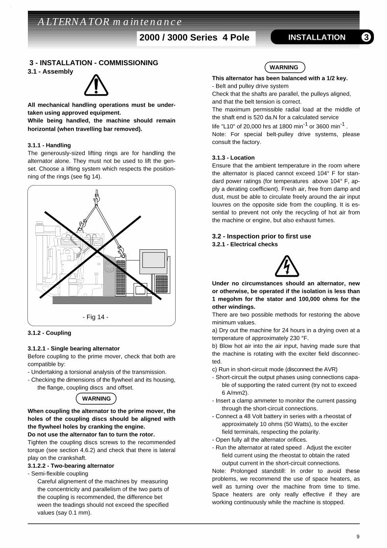
All mechanical handling operations must be under-taken using approved equipment.While being handled, the machine should remainhorizontal (when travelling bar removed).
3.1.1 - HandlingThe generously-sized lifting rings are for handling thealternator alone. They must not be used to lift the gen-set. Choose a lifting system which respects the position-ning of the rings (see fig 14).
3.1.2 - Coupling
3.1.2.1 - Single bearing alternatorBefore coupling to the prime mover, check that both arecompatible by:- Undertaking a torsional analysis of the transmission.- Checking the dimensions of the flywheel and its housing,
the flange, coupling discs and offset.
When coupling the alternator to the prime mover, theholes of the coupling discs should be aligned withthe flywheel holes by cranking the engine.Do not use the alternator fan to turn the rotor.Tighten the coupling discs screws to the recommendedtorque (see section 4.6.2) and check that there is lateralplay on the crankshaft.3.1.2.2 - Two-bearing alternator- Semi-flexible coupling
Careful alignement of the machines by measuring the concentricity and parallelism of the two parts of the coupling is recommended, the difference between the teadings should not exceed the specified values (say 0.1 mm).
This alternator has been balanced with a 1/2 key.- Belt and pulley drive systemCheck that the shafts are parallel, the pulleys aligned,and that the belt tension is correct.The maximum permissible radial load at the middle ofthe shaft end is 520 da.N for a calculated service
life "L10" of 20,000 hrs at 1800 min-1 or 3600 min-1 .Note: For special belt-pulley drive systems, pleaseconsult the factory.
3.1.3 - LocationEnsure that the ambient temperature in the room wherethe alternator is placed cannot exceed 104° F for stan-dard power ratings (for temperatures above 104° F, ap-ply a derating coefficient). Fresh air, free from damp anddust, must be able to circulate freely around the air inputlouvres on the opposite side from the coupling. It is es-sential to prevent not only the recycling of hot air fromthe machine or engine, but also exhaust fumes.
3.2 - Inspection prior to first use3.2.1 - Electrical checks
Under no circumstances should an alternator, newor otherwise, be operated if the isolation is less than1 megohm for the stator and 100,000 ohms for theother windings.There are two possible methods for restoring the aboveminimum values.a) Dry out the machine for 24 hours in a drying oven at atemperature of approximately 230 °F.b) Blow hot air into the air input, having made sure thatthe machine is rotating with the exciter field disconnec-ted.c) Run in short-circuit mode (disconnect the AVR)- Short-circuit the output phases using connections capa-
ble of supporting the rated current (try not to exceed 6 A/mm2).
- Insert a clamp ammeter to monitor the current passing through the short-circuit connections.
- Connect a 48 Volt battery in series with a rheostat of approximately 10 ohms (50 Watts), to the exciter field terminals, respecting the polarity.
- Open fully all the alternator orifices.- Run the alternator at rated speed . Adjust the exciter
field current using the rheostat to obtain the rated output current in the short-circuit connections.
Note: Prolonged standstill: In order to avoid theseproblems, we recommend the use of space heaters, aswell as turning over the machine from time to time.Space heaters are only really effective if they areworking continuously while the machine is stopped.
9
ALTERNATOR maintenance 2000 / 3000 Series 4 Pole
WARNING
- Fig 14 -
WARNING
INSTALLATION 3
10
ALTERNATOR maintenance 2000 / 3000 Series 4 Pole
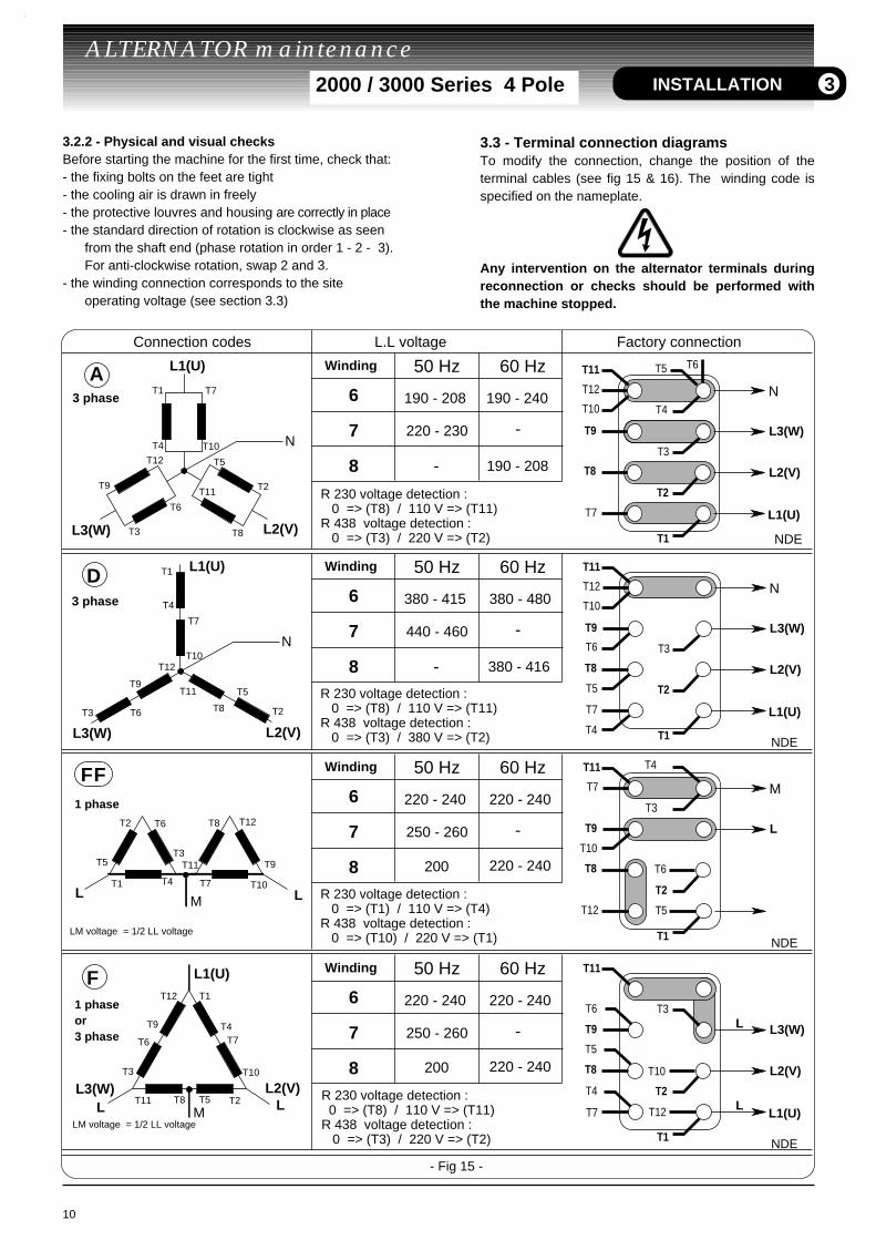
Connection codes L.L voltage Factory connection
L1(U)
N
L3(W)
T1 T7
T12T10T4
T9
T3
T6
T11
T5
T2
T8 L2(V)
A3 phase
3 phase
Winding 60 Hz50 Hz
190 - 208 190 - 240
220 - 230 -
- 190 - 208
6
7
8
N
T1
T7
T12T10
T4
T9
T3 T6
T11 T5
T2T8
L1(U)
L3(W) L2(V)
D
F L1(U)
M
L3(W)
T1
T7
T12
T10
T4T9
T3
T6
T11 T5 T2T8L2(V)
LM voltage = 1/2 LL voltage
R 230 voltage detection : 0 => (T8) / 110 V => (T11)R 438 voltage detection : 0 => (T3) / 220 V => (T2)
N
L1(U)
L2(V)
L3(W)
NDE
T9
T8
T7
T12
T10
T11
T4
T3
T2
T1
T5 T6
- Fig 15 -
Winding 60 Hz50 Hz
380 - 415 380 - 480
440 - 460 -
- 380 - 416
6
7
8R 230 voltage detection : 0 => (T8) / 110 V => (T11)R 438 voltage detection : 0 => (T3) / 380 V => (T2) NDE
N
L1(U)
L2(V)
L3(W)
L1(U)
L2(V)
L3(W)
T9
T8
T7
T12
T10
T11
T4
T3
T2
T1
T5
T6
1 phase
1 phaseor3 phase
FF Winding 60 Hz50 Hz
220 - 240 220 - 240
220 - 240200
250 - 260 -
6
7
8R 230 voltage detection : 0 => (T1) / 110 V => (T4)R 438 voltage detection : 0 => (T10) / 220 V => (T1) NDE
M
L
L
LT9
T8
T7
T12
T10
T11 T4
T3
T2
T1
T5
T6
Winding 60 Hz50 Hz
220 - 240 220 - 240
220 - 240200
250 - 260 -
6
7
8
NDE
T9
T8
T7 T12
T10
T11
T4
T3
T2
T1
T5
T6
L
L L
T1 T7
T12
T10T4
T9T3
T6
T11T5
T2 T8
LM
LM voltage = 1/2 LL voltage
R 230 voltage detection : 0 => (T8) / 110 V => (T11)R 438 voltage detection : 0 => (T3) / 220 V => (T2)
3.2.2 - Physical and visual checksBefore starting the machine for the first time, check that:- the fixing bolts on the feet are tight- the cooling air is drawn in freely- the protective louvres and housing are correctly in place- the standard direction of rotation is clockwise as seen
from the shaft end (phase rotation in order 1 - 2 - 3). For anti-clockwise rotation, swap 2 and 3.
- the winding connection corresponds to the site operating voltage (see section 3.3)
3.3 - Terminal connection diagramsTo modify the connection, change the position of theterminal cables (see fig 15 & 16). The winding code isspecified on the nameplate.
Any intervention on the alternator terminals duringreconnection or checks should be performed withthe machine stopped.
INSTALLATION 3
o.ayesh
Rectangle
o.ayesh
Rectangle
o.ayesh
Rectangle
o.ayesh
Rectangle
o.ayesh
Rectangle
o.ayesh
Rectangle
o.ayesh
Rectangle
o.ayesh
Rectangle
o.ayesh
Rectangle
o.ayesh
Rectangle
o.ayesh
Rectangle
o.ayesh
Rectangle
o.ayesh
Rectangle
o.ayesh
Rectangle
o.ayesh
Rectangle
11
ALTERNATOR maintenance 2000 / 3000 Series 4 Pole
1 PHMT1
T7T12
T10
T4
T9
T3
T6
T11
T5T2
T8
LM voltage = 1/2 LL voltage
Connection not recommended
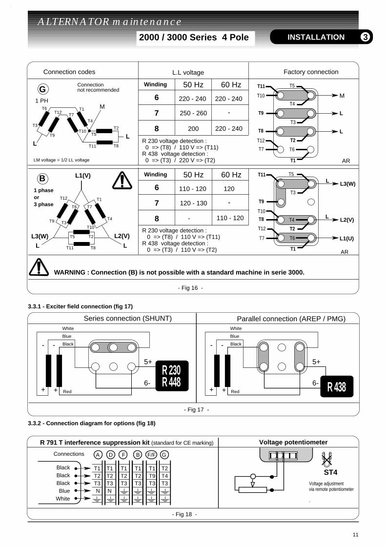
Connection codes L.L voltage Factory connection
LL
GWinding 60 Hz50 Hz
220 - 240 220 - 240
250 - 260
200
-
220 - 240
6
7
8R 230 voltage detection : 0 => (T8) / 110 V => (T11)R 438 voltage detection : 0 => (T3) / 220 V => (T2)
M
L
L
AR
T9
T8
T7
T12
T10
T11
T4
T3
T2
T1
T5
T6
- Fig 16 -
1 phaseor3 phase
L1(U)
L2(V)
L3(W)L
L
Winding 60 Hz50 Hz
110 - 120 120
110 - 120-
120 - 130 -
6
7
8R 230 voltage detection : 0 => (T8) / 110 V => (T11)R 438 voltage detection : 0 => (T3) / 110 V => (T2) AR
T9
T8
T7
T12
T10
T11
T4
T3
T2
T1
T5
T6
LL
L3(W)
T1
T7
T10T9 T3
T6
T11
T5 T2
T8
L2(V)
B
T12
T4
L1(V)
WARNING : Connection (B) is not possible with a standard machine in serie 3000.
3.3.1 - Exciter field connection (fig 17)
3.3.2 - Connection diagram for options (fig 18)
Series connection (SHUNT) Parallel connection (AREP / PMG)
- Fig 17 -
6-5+
6-
Black
White
Blue
Red
Black
White
Blue
Red+ +
- -
R 230R 448
6-5+
6-+ +
- -
R 438
INSTALLATION 3
- Fig 18 -
R 791 T interference suppression kit (standard for CE marking) Voltage potentiometer
BlackBlackBlackBlue
White
Connections A D F B F/F G
T1 T1 T1 T1 T1 T2 T2 T2 T2 T2 T9 T4 T3 T3 T3 T3 T3 T3 N N
Voltage adjustmentvia remote potentiometer .
ST4
12
ALTERNATOR maintenance 2000 / 3000 Series 4 Pole
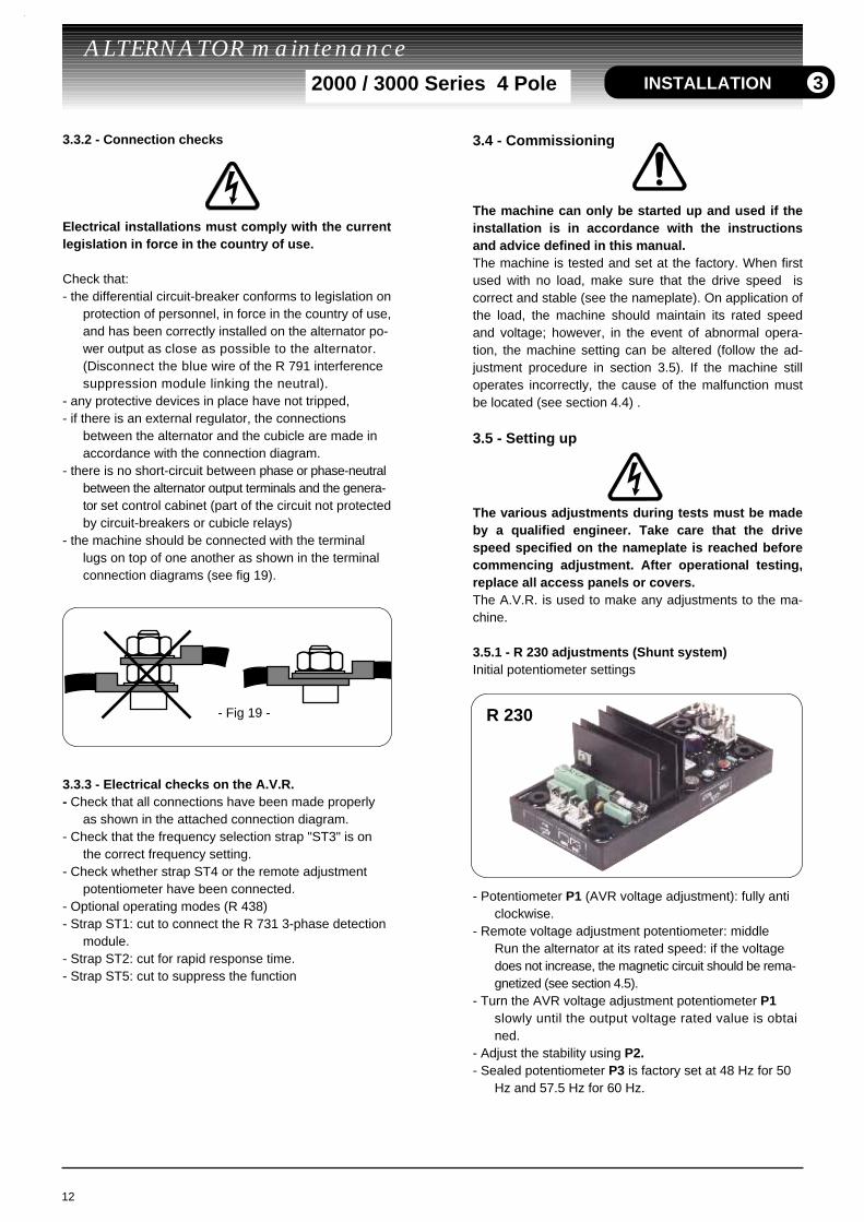
3.3.2 - Connection checks
Electrical installations must comply with the currentlegislation in force in the country of use.
Check that:- the differential circuit-breaker conforms to legislation on
protection of personnel, in force in the country of use,and has been correctly installed on the alternator po-wer output as close as possible to the alternator. (Disconnect the blue wire of the R 791 interference suppression module linking the neutral).
- any protective devices in place have not tripped,- if there is an external regulator, the connections
between the alternator and the cubicle are made in accordance with the connection diagram.
- there is no short-circuit between phase or phase-neutral between the alternator output terminals and the genera-tor set control cabinet (part of the circuit not protectedby circuit-breakers or cubicle relays)
- the machine should be connected with the terminal lugs on top of one another as shown in the terminal connection diagrams (see fig 19).
3.3.3 - Electrical checks on the A.V.R.- Check that all connections have been made properly
as shown in the attached connection diagram.- Check that the frequency selection strap "ST3" is on
the correct frequency setting.- Check whether strap ST4 or the remote adjustment
potentiometer have been connected.- Optional operating modes (R 438)- Strap ST1: cut to connect the R 731 3-phase detection
module.- Strap ST2: cut for rapid response time.- Strap ST5: cut to suppress the function
- Fig 19 -
INSTALLATION
3.4 - Commissioning
The machine can only be started up and used if theinstallation is in accordance with the instructionsand advice defined in this manual.The machine is tested and set at the factory. When firstused with no load, make sure that the drive speed iscorrect and stable (see the nameplate). On application ofthe load, the machine should maintain its rated speedand voltage; however, in the event of abnormal opera-tion, the machine setting can be altered (follow the ad-justment procedure in section 3.5). If the machine stilloperates incorrectly, the cause of the malfunction mustbe located (see section 4.4) .
3.5 - Setting up
The various adjustments during tests must be madeby a qualified engineer. Take care that the drivespeed specified on the nameplate is reached beforecommencing adjustment. After operational testing,replace all access panels or covers.The A.V.R. is used to make any adjustments to the ma-chine.
3.5.1 - R 230 adjustments (Shunt system)Initial potentiometer settings
- Potentiometer P1 (AVR voltage adjustment): fully anticlockwise.
- Remote voltage adjustment potentiometer: middleRun the alternator at its rated speed: if the voltage does not increase, the magnetic circuit should be rema-gnetized (see section 4.5).
- Turn the AVR voltage adjustment potentiometer P1 slowly until the output voltage rated value is obtained.
- Adjust the stability using P2.- Sealed potentiometer P3 is factory set at 48 Hz for 50
Hz and 57.5 Hz for 60 Hz.
3
R 230
Hz for 50 Hz, or 58 for 60 Hz.
h) Adjust the output voltage to the desired value using P2.- rated voltage UN for solo operation (eg. 400 V)- or UN + 2 to 4% for parallel operation with C.T.
(eg. 410V -)If the voltage oscillates, use P3 to make adjustments (try both directions) observing the voltage between E+ and E- (approx. 10V D.C.). The best response ti-mes are obtained at the limit of the instability. If no sta-ble position can be obtained, try cutting or replacing the ST2 strap (normal /rapid).
i) Check LAM operation : ST5 closed
j)Turn potentiometer P4 slowly anti-clockwise until there is a significant voltage drop (approx. 15 %).
k) Vary the frequency (speed) of both parts between 48or 58 Hz according to the operating frequency, andcheck the change in voltage previously observed (~ 15%).l) Readjust the speed of the unit to its rated no-load value.
- Adjustments in parallel operation
Before any intervention on the alternator, make sure thatthe speed quadrature droop is identical for all engine.
m) Preset for parallel operation (with C.T. connected toS1, S2 of connector J2)- potentiometer P1 (quadrature droop) in centre positionApply the rated load (P.F. = 0.8 inductive).The voltage should drop by 2 to 3 %. If it increases,swap the 2 incoming wires of the C.T. secondary.
n) The no-load voltages should be identical for all thealternators intended to run in parallel.- Couple the machines in parallel.- By adjusting the speed, try to obtain 0 Kw power
exchange.- By altering the voltage setting P2 or Rhe on one of the
machines, try to cancel (or minimise) the current circulating between the machines.
- From now on, do not touch the voltage settings.
o) Apply the available load (the setting is only correct if areactive load is available)- By altering the speed, equalize the KW (or divide the rated
power of the units proportionally).- By altering the quadrature droop potentiometer P1,
equalize or divide the currents.
13
ALTERNATOR maintenance 2000 / 3000 Series 4 Pole INSTALLATION
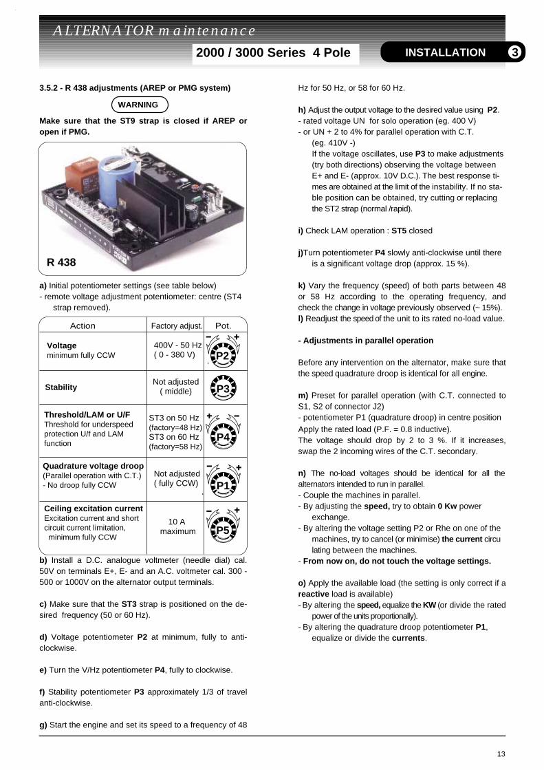
3.5.2 - R 438 adjustments (AREP or PMG system)
Make sure that the ST9 strap is closed if AREP oropen if PMG.
a) Initial potentiometer settings (see table below)- remote voltage adjustment potentiometer: centre (ST4
strap removed).
b) Install a D.C. analogue voltmeter (needle dial) cal.50V on terminals E+, E- and an A.C. voltmeter cal. 300 -500 or 1000V on the alternator output terminals.
c) Make sure that the ST3 strap is positioned on the de-sired frequency (50 or 60 Hz).
d) Voltage potentiometer P2 at minimum, fully to anti-clockwise.
e) Turn the V/Hz potentiometer P4, fully to clockwise.
f) Stability potentiometer P3 approximately 1/3 of travelanti-clockwise.
g) Start the engine and set its speed to a frequency of 48
Action Factory adjust. Pot.
P2
P3
P4
P1
P5
Voltage minimum fully CCW
400V - 50 Hz( 0 - 380 V)
StabilityNot adjusted
( middle)
Threshold/LAM or U/FThreshold for underspeed protection U/f and LAM function
ST3 on 50 Hz(factory=48 Hz)ST3 on 60 Hz(factory=58 Hz)
Quadrature voltage droop(Parallel operation with C.T.)- No droop fully CCW
Not adjusted( fully CCW)
Ceiling excitation currentExcitation current and short circuit current limitation, minimum fully CCW
10 A maximum
3
R 438
WARNING
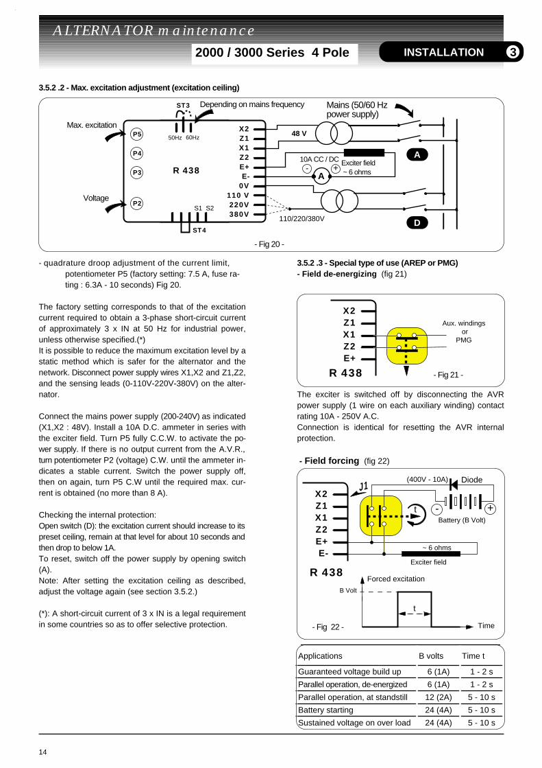
3.5.2 .2 - Max. excitation adjustment (excitation ceiling)
- quadrature droop adjustment of the current limit, potentiometer P5 (factory setting: 7.5 A, fuse ra-ting : 6.3A - 10 seconds) Fig 20.
The factory setting corresponds to that of the excitationcurrent required to obtain a 3-phase short-circuit currentof approximately 3 x IN at 50 Hz for industrial power,unless otherwise specified.(*)It is possible to reduce the maximum excitation level by astatic method which is safer for the alternator and thenetwork. Disconnect power supply wires X1,X2 and Z1,Z2,and the sensing leads (0-110V-220V-380V) on the alter-nator.
Connect the mains power supply (200-240V) as indicated(X1,X2 : 48V). Install a 10A D.C. ammeter in series withthe exciter field. Turn P5 fully C.C.W. to activate the po-wer supply. If there is no output current from the A.V.R.,turn potentiometer P2 (voltage) C.W. until the ammeter in-dicates a stable current. Switch the power supply off,then on again, turn P5 C.W until the required max. cur-rent is obtained (no more than 8 A).
Checking the internal protection:Open switch (D): the excitation current should increase to itspreset ceiling, remain at that level for about 10 seconds andthen drop to below 1A.To reset, switch off the power supply by opening switch(A).Note: After setting the excitation ceiling as described,adjust the voltage again (see section 3.5.2.)
(*): A short-circuit current of 3 x IN is a legal requirementin some countries so as to offer selective protection.
3.5.2 .3 - Special type of use (AREP or PMG) - Field de-energizing (fig 21)
The exciter is switched off by disconnecting the AVRpower supply (1 wire on each auxiliary winding) contactrating 10A - 250V A.C.Connection is identical for resetting the AVR internalprotection.
- Field forcing (fig 22)
14
ALTERNATOR maintenance 2000 / 3000 Series 4 Pole
R 438
X2Z1X1Z2E+
Aux. windings or PMG
- Fig 21 -
R 438
X2Z1X1Z2E+E-
Battery (B Volt)
J1
+-t
(400V - 10A)
Exciter field
~ 6 ohms
Diode
t
B Volt
Forced excitation
Time- Fig 22 -
INSTALLATION
Mains (50/60 Hzpower supply)
Depending on mains frequency
Max. excitation
Voltage
- Fig 20 -
Exciter field ~ 6 ohmsR 438
X2Z1X1Z2E+E-
0V110 V220V380V
50Hz 60Hz
S1 S2P2
P3
P4
P5
ST3
10A CC / DC
ST4
A+-
48 V
110/220/380V
A
D
3
Applications B volts Time t
Guaranteed voltage build up 6 (1A) 1 - 2 s
Parallel operation, de-energized 6 (1A) 1 - 2 s
Parallel operation, at standstill 12 (2A) 5 - 10 s
Battery starting 24 (4A) 5 - 10 s
Sustained voltage on over load 24 (4A) 5 - 10 s
4 - SERVICING - MAINTENANCE4.1 - Safety measures
Servicing or troubleshooting must be carried outstrictly in accordance with instructions so as toavoid the risk of accidents and to maintain themachine in its original state.
All such operations performed on the alternatorshould be undertaken by personnel with training incommissioning, servicing and maintenance ofelectrical and mechanical components.Before any intervention on the machine, ensure that itcannot be started by a manual or automatic system andthat you have understood the operating principles of thesystem.
4.2 - Regular maintenance
4.2.1 - Checks after start-upAfter approximately 20 hours of operation, check that allfixing screws on the machine are still tight, plus thegeneral state of the machine and the variouselectrical connections in the installation.
4.2.2 - Cooling circuitIt is advisable to check that circulation of air is notreduced by partial blocking of the suction and dischargelouvres: mud, fibre, grease, etc.
4.2.3 - BearingsThe bearings are greased for life: approximate life of thegrease (depending on use) = 20,000 hours or 3 years.Monitor the temperature rise in the bearings, whichshould not exceed 60°C above the ambient temperature.Should this value be exceeded, the machine must bestopped and checks carried out.
4.2.4 Electrical servicing- Cleaning product for the windings
DO NOT USE: TRICHLORETHYLENE, PERCHLORETH-YLENE, TRICHLOROETHANE and ANY ALKALINEPRODUCTS.
Certain strictly defined pure volatile degreasing productscan be used, such as:- Normal petrol (without additives)- Toluene (slightly toxic); flammable- Benzene (or benzine, toxic); flammable- Ciclohexare (non toxic); flammable
Cleaning the stator, rotor, exciter and diode bridge
The isolating components and the impregnation systemare not at risk of damage from solvents (see the list ofauthorised products above).Avoid letting the cleaning product run into the slots.Apply the product with a brush, sponging frequently toavoid accumulation in the housing. Dry the winding witha dry cloth. Let any traces evaporate before reassem-bling the machine.After cleaning the alternator it is essential to check theisolation of the windings (see sections 3.2. and 4.8).
4.2.5 Mechanical maintenance
Water and/or Pressure wash are strictly prohibited.Any problems caused by such treatement are not co-vered by our warranty.Degreasing : Use a brush and detergent (adapted topaint).Dusting : Use an air gun.If a machine is fitted with air inlet and outlet filters, in or-der to ensure correct ventilation, a regular cleaning ofthe filters must be done according to the environmentconditions.After cleaning the alternator, it is essential to check theinsulation of the windings (see sections 3.2. and 4.8).
4.3 - Fault detectionIf, when first commissioned, the alternator does not worknormally, the source of the malfunction must beidentified.To do this, check that:- the protective devices are fitted correctly - all connections comply with the diagrams in the manuals supplied with the machine.- the speed of the unit is correct (see section 1.2.2).Repeat the operations defined in section 3.
15
ALTERNATOR maintenance 2000 / 3000 Series 4 Pole
WARNING
SERVICING 4
WARNING
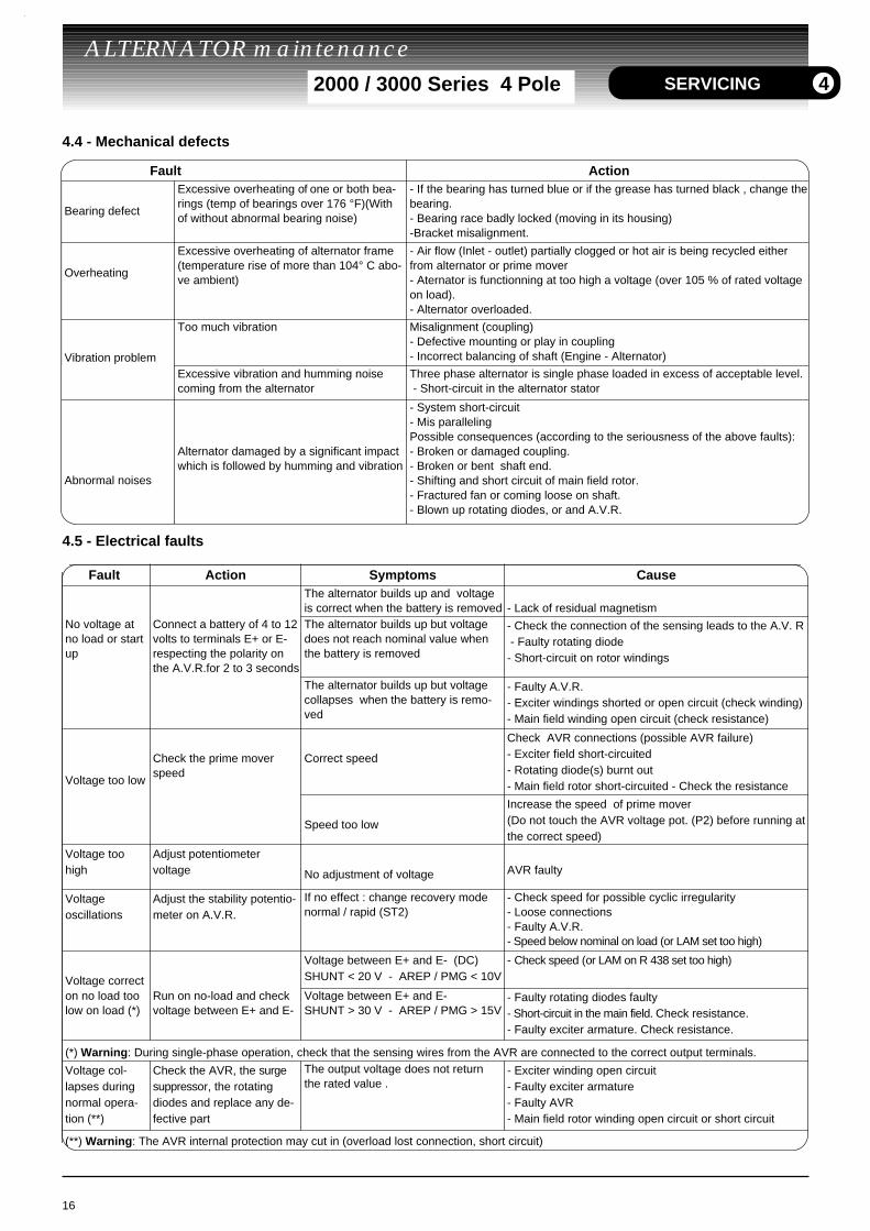
4.4 - Mechanical defects
4.5 - Electrical faults
16
ALTERNATOR maintenance 2000 / 3000 Series 4 Pole SERVICING 4
Fault Action Symptoms CauseThe alternator builds up and voltageis correct when the battery is removed - Lack of residual magnetism
No voltage atno load or startup
Connect a battery of 4 to 12volts to terminals E+ or E-respecting the polarity onthe A.V.R.for 2 to 3 seconds
The alternator builds up but voltagedoes not reach nominal value whenthe battery is removed
- Check the connection of the sensing leads to the A.V. R - Faulty rotating diode- Short-circuit on rotor windings
The alternator builds up but voltagecollapses when the battery is remo-ved
- Faulty A.V.R.- Exciter windings shorted or open circuit (check winding)- Main field winding open circuit (check resistance)
Voltage too low
Check the prime moverspeed
Correct speed
Check AVR connections (possible AVR failure)- Exciter field short-circuited- Rotating diode(s) burnt out- Main field rotor short-circuited - Check the resistance
Speed too low
Increase the speed of prime mover (Do not touch the AVR voltage pot. (P2) before running atthe correct speed)
Voltage toohigh
Adjust potentiometer voltage No adjustment of voltage AVR faulty
Voltageoscillations
Adjust the stability potentio-meter on A.V.R.
If no effect : change recovery modenormal / rapid (ST2)
- Check speed for possible cyclic irregularity- Loose connections- Faulty A.V.R.- Speed below nominal on load (or LAM set too high)
Voltage correct
Voltage between E+ and E- (DC)SHUNT < 20 V - AREP / PMG < 10V
- Check speed (or LAM on R 438 set too high)
on no load toolow on load (*)
Run on no-load and checkvoltage between E+ and E-
Voltage between E+ and E- SHUNT > 30 V - AREP / PMG > 15V
- Faulty rotating diodes faulty- Short-circuit in the main field. Check resistance.- Faulty exciter armature. Check resistance.
(*) Warning: During single-phase operation, check that the sensing wires from the AVR are connected to the correct output terminals.
Voltage col-lapses duringnormal opera-tion (**)
Check the AVR, the surgesuppressor, the rotatingdiodes and replace any de-fective part
The output voltage does not returnthe rated value .
- Exciter winding open circuit- Faulty exciter armature- Faulty AVR- Main field rotor winding open circuit or short circuit
(**) Warning: The AVR internal protection may cut in (overload lost connection, short circuit)
Fault Action
Bearing defect
Excessive overheating of one or both bea-rings (temp of bearings over 176 °F)(Withof without abnormal bearing noise)
- If the bearing has turned blue or if the grease has turned black , change thebearing.- Bearing race badly locked (moving in its housing)-Bracket misalignment.
Overheating
Excessive overheating of alternator frame(temperature rise of more than 104° C abo-ve ambient)
- Air flow (Inlet - outlet) partially clogged or hot air is being recycled eitherfrom alternator or prime mover- Aternator is functionning at too high a voltage (over 105 % of rated voltageon load).- Alternator overloaded.
Vibration problem
Too much vibration Misalignment (coupling)- Defective mounting or play in coupling- Incorrect balancing of shaft (Engine - Alternator)
Excessive vibration and humming noisecoming from the alternator
Three phase alternator is single phase loaded in excess of acceptable level. - Short-circuit in the alternator stator
Abnormal noises
Alternator damaged by a significant impactwhich is followed by humming and vibration
- System short-circuit- Mis parallelingPossible consequences (according to the seriousness of the above faults):- Broken or damaged coupling.- Broken or bent shaft end.- Shifting and short circuit of main field rotor.- Fractured fan or coming loose on shaft.- Blown up rotating diodes, or and A.V.R.
4.5.1 - Checking the windings You can check the winding insulation making a high vol-tage test. In this case, you must disconnect all AVR wi-res.
Damages occuring to avr in such conditions will notbe taken into account in a warranty claim.
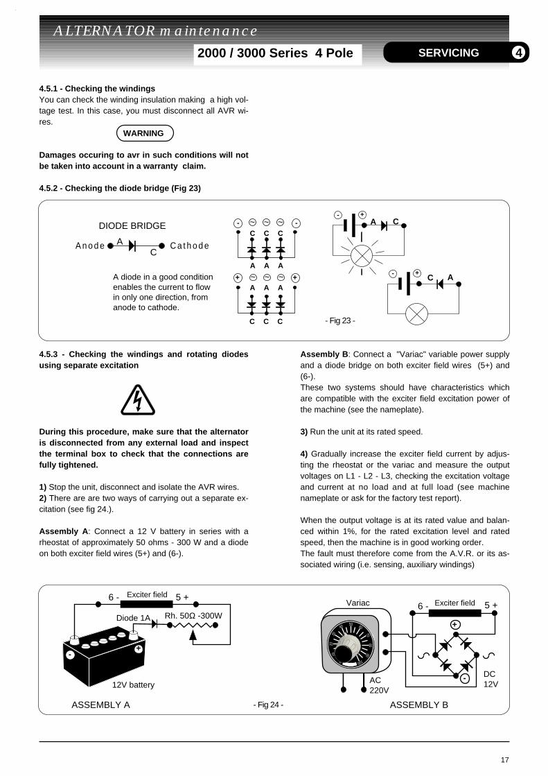
4.5.2 - Checking the diode bridge (Fig 23)
4.5.3 - Checking the windings and rotating diodesusing separate excitation
During this procedure, make sure that the alternatoris disconnected from any external load and inspectthe terminal box to check that the connections arefully tightened.
1) Stop the unit, disconnect and isolate the AVR wires.2) There are are two ways of carrying out a separate ex-citation (see fig 24.). Assembly A: Connect a 12 V battery in series with arheostat of approximately 50 ohms - 300 W and a diodeon both exciter field wires (5+) and (6-).
Assembly B: Connect a "Variac" variable power supplyand a diode bridge on both exciter field wires (5+) and(6-). These two systems should have characteristics whichare compatible with the exciter field excitation power ofthe machine (see the nameplate).
3) Run the unit at its rated speed.
4) Gradually increase the exciter field current by adjus-ting the rheostat or the variac and measure the outputvoltages on L1 - L2 - L3, checking the excitation voltageand current at no load and at full load (see machinenameplate or ask for the factory test report).
When the output voltage is at its rated value and balan-ced within 1%, for the rated excitation level and ratedspeed, then the machine is in good working order.The fault must therefore come from the A.V.R. or its as-sociated wiring (i.e. sensing, auxiliary windings)
17
ALTERNATOR maintenance 2000 / 3000 Series 4 Pole
6 - 5 +
Diode 1A
12V battery
Rh. 50Ω -300W
- Fig 24 -
-
-
+
+
6 - 5 + Variac
AC220V
DC12V
50 60
7080
90
100
40
3020
10
0
ASSEMBLY A ASSEMBLY B
Exciter fieldExciter field
SERVICING 4
- -C C C
A A A
+
C C C
A A A+
~ ~ ~
~ ~ ~
- Fig 23 -
DIODE BRIDGE
CAA n o d e C a t h o d e
-CA
+
- C A+
A diode in a good condition enables the current to flow in only one direction, from anode to cathode.
WARNING
4.6 - Dismantling, reassembly (see section 5.5.1. & 5.5.2.)
During the warranty period, this operationshould only be carried out in a LEROY SOMERapproved workshop or in our factory, otherwisethe warranty may be invalidated.
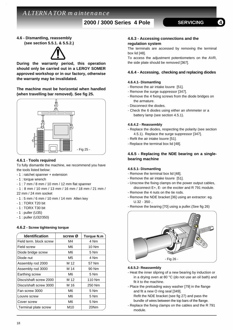
The machine must be horizontal when handled(when travelling bar removed). See fig 25.
4.6.1 - Tools requiredTo fully dismantle the machine, we recommend you havethe tools listed below:- 1 : ratchet spanner + extension- 1 : torque wrench- 1 : 7 mm / 8 mm / 10 mm / 12 mm flat spanner- 1 : 8 mm / 10 mm / 13 mm / 16 mm / 18 mm / 21 mm /22 mm / 24 mm socket- 1 : 5 mm / 6 mm / 10 mm / 14 mm Allen key - 1 : TORX T20 bit- 1 : TORX T30 bit- 1 : puller (U35)- 1 : puller (U32/350)
4.6.2 - Screw tightening torque
4.6.3 - Accessing connections and the regulation system The terminals are accessed by removing the terminalbox lid [48].To access the adjustment potentiometers on the AVR,the side plate should be removed [367].
4.6.4 - Accessing, checking and replacing diodes
4.6.4.1- Dismantling - Remove the air intake louvre [51].- Remove the surge suppressor [347].- Remove the 4 fixing screws from the diode bridges on
the armature.- Disconnect the diodes. - Check the 6 diodes using either an ohmmeter or a
battery lamp (see section 4.5.1).
4.6.4.2 - Reassembly- Replace the diodes, respecting the polarity (see section
4.5.1). Replace the surge suppressor [347]. - Refit the air intake louvre [51].- Replace the terminal box lid [48].
4.6.5 - Replacing the NDE bearing on a single-bearing machine
4.6.5.1- Dismantling- Remove the terminal box lid [48].- Remove the air intake louvre [51].- Unscrew the fixing clamps on the power output cables,
disconnect E+, E- on the exciter and R 791 module.- Remove the 4 nuts on the tie rods.- Remove the NDE bracket [36] using an extractor: eg.
U.32 - 350 ..- Remove the bearing [70] using a puller.(See fig 26)
4.6.5.2- Reassembly- Heat the inner slipring of a new bearing by induction or
in a drying oven at 80 °C (do not use an oil bath) andfit it to the machine.
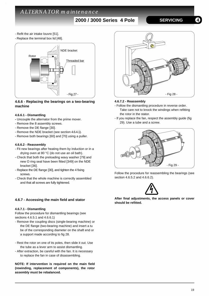
- Place the preloading wavy washer [79] in the flange and fit a new O ring seal [349].Refit the NDE bracket (see fig 27) and pass the bundle of wires between the top bars of the flange.
- Replace the fixing clamps on the cables and the R 791 module.
18
ALTERNATOR maintenance 2000 / 3000 Series 4 Pole SERVICING
- Fig 25 -
4
Identification screw Ø Torque N.mField term. block screw M4 4 Nm
Field screw M6 10 Nm
Diode bridge screw M6 5 Nm
Diode nut M5 4 Nm
Assembly rod 2000 M 12 57 Nm
Assembly rod 3000 M 14 90 Nm
Earthing screw M6 5 Nm
Discs/shaft screw 2000 M 12 110 Nm
Discs/shaft screw 3000 M 16 250 Nm
Fan screw 3000 M6 5 Nm
Louvre screw M6 5 Nm
Cover screw M6 5 Nm
Terminal plate screw M10 20Nm
- Fig 26 -
- Refit the air intake louvre [51].- Replace the terminal box lid [48].
4.6.6 - Replacing the bearings on a two-bearingmachine
4.6.6.1 - Dismantling- Uncouple the alternator from the prime mover.- Remove the 8 assembly screws.- Remove the DE flange [30].- Remove the NDE bracket (see section 4.6.4.1).- Remove both bearings [60] and [70] using a puller.
4.6.6.2 - Reassembly- Fit new bearings after heating them by induction or in a
drying oven at 80 °C (do not use an oil bath).- Check that both the preloading wavy washer [79] and
new O ring seal have been fitted [349] on the NDE bracket [36].
- Replace the DE flange [30], and tighten the 4 fixing screws.
- Check that the whole machine is correctly assembled and that all screws are fully tightened.
4.6.7 - Accessing the main field and stator
4.6.7.1 - DismantlingFollow the procedure for dismantling bearings (see sections 4.6.5.1 and 4.6.6.1)- Remove the coupling discs (single-bearing machine) or
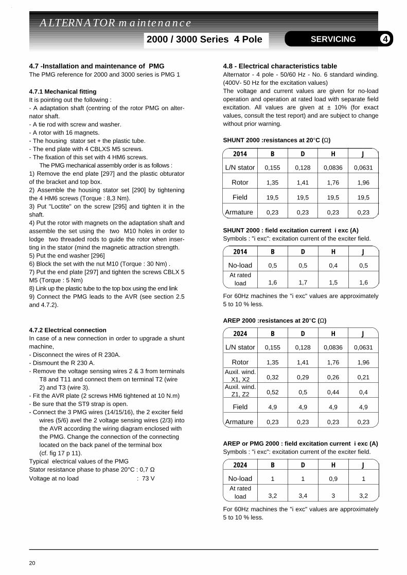
the DE flange (two-bearing machine) and insert a tube of the corresponding diameter on the shaft end or a support made according to fig 28.
- Rest the rotor on one of its poles, then slide it out. Use the tube as a lever arm to assist dismantling.
- After extraction, be careful with the fan. It is necessary to replace the fan in case of disassembling.
NOTE: If intervention is required on the main field(rewinding, replacement of components), the rotorassembly must be rebalanced.
4.6.7.2 - Reassembly- Follow the dismantling procedure in reverse order.
Take care not to knock the windings when refitting the rotor in the stator.
- If you replace the fan, respect the assembly guide (fig 29). Use a tube and a screw.
Follow the procedure for reassembling the bearings (seesection 4.6.5.2 and 4.6.6.2).
After final adjustments, the access panels or covershould be refitted.
19
ALTERNATOR maintenance 2000 / 3000 Series 4 Pole SERVICING
- Fig 28 -
- Fig 29 -
4
- Fig 27 -
Rotor
NDE bracket
Threaded bar
4.7 -Installation and maintenance of PMG The PMG reference for 2000 and 3000 series is PMG 1
4.7.1 Mechanical fittingIt is pointing out the following :- A adaptation shaft (centring of the rotor PMG on alter-nator shaft.- A tie rod with screw and washer.- A rotor with 16 magnets.- The housing stator set + the plastic tube.- The end plate with 4 CBLXS M5 screws.- The fixation of this set with 4 HM6 screws.
The PMG mechanical assembly order is as follows :1) Remove the end plate [297] and the plastic obturatorof the bracket and top box.2) Assemble the housing stator set [290] by tighteningthe 4 HM6 screws (Torque : 8,3 Nm).3) Put "Loctite" on the screw [295] and tighten it in theshaft.4) Put the rotor with magnets on the adaptation shaft andassemble the set using the two M10 holes in order tolodge two threaded rods to guide the rotor when inser-ting in the stator (mind the magnetic attraction strength.5) Put the end washer [296]6) Block the set with the nut M10 (Torque : 30 Nm) .7) Put the end plate [297] and tighten the screws CBLX 5M5 (Torque : 5 Nm) 8) Link up the plastic tube to the top box using the end link9) Connect the PMG leads to the AVR (see section 2.5and 4.7.2).
4.7.2 Electrical connectionIn case of a new connection in order to upgrade a shuntmachine,- Disconnect the wires of R 230A.- Dismount the R 230 A.- Remove the voltage sensing wires 2 & 3 from terminals
T8 and T11 and connect them on terminal T2 (wire 2) and T3 (wire 3).
- Fit the AVR plate (2 screws HM6 tightened at 10 N.m)- Be sure that the ST9 strap is open.- Connect the 3 PMG wires (14/15/16), the 2 exciter field
wires (5/6) avel the 2 voltage sensing wires (2/3) intothe AVR according the wiring diagram enclosed with the PMG. Change the connection of the connecting located on the back panel of the terminal box
(cf. fig 17 p 11).Typical electrical values of the PMGStator resistance phase to phase 20°C : 0,7 ΩVoltage at no load : 73 V
4.8 - Electrical characteristics tableAlternator - 4 pole - 50/60 Hz - No. 6 standard winding.(400V- 50 Hz for the excitation values)The voltage and current values are given for no-loadoperation and operation at rated load with separate fieldexcitation. All values are given at ± 10% (for exactvalues, consult the test report) and are subject to changewithout prior warning.
SHUNT 2000 :resistances at 20°C (Ω)
SHUNT 2000 : field excitation current i exc (A) Symbols : "i exc": excitation current of the exciter field.
For 60Hz machines the "i exc" values are approximately5 to 10 % less.
AREP 2000 :resistances at 20°C (Ω)
AREP or PMG 2000 : field excitation current i exc (A)Symbols : "i exc": excitation current of the exciter field.
For 60Hz machines the "i exc" values are approximately5 to 10 % less.
20
ALTERNATOR maintenance 2000 / 3000 Series 4 Pole SERVICING 4
2014 B D H J
L/N stator 0,155 0,128 0,0836 0,0631
Rotor 1,35 1,41 1,76 1,96
Field 19,5 19,5 19,5 19,5
Armature 0,23 0,23 0,23 0,23
2014 B D H J
No-load 0,5 0,5 0,4 0,5
At ratedload 1,6 1,7 1,5 1,6
2024 B D H J
L/N stator 0,155 0,128 0,0836 0,0631
Rotor 1,35 1,41 1,76 1,96
Auxil. wind.X1, X2 0,32 0,29 0,26 0,21
Auxil. wind.Z1, Z2 0,52 0,5 0,44 0,4
Field 4,9 4,9 4,9 4,9
Armature 0,23 0,23 0,23 0,23
2024 B D H J
No-load 1 1 0,9 1
At ratedload 3,2 3,4 3 3,2
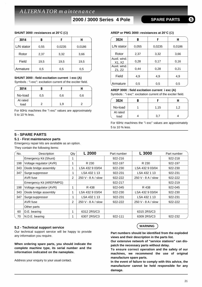
SHUNT 3000 :resistances at 20°C (Ω)
SHUNT 3000 : field excitation current i exc (A) Symbols : "i exc": excitation current of the exciter field.
For 60Hz machines the "i exc" values are approximately5 to 10 % less.
5 - SPARE PARTS5.1 - First maintenance partsEmergency repair kits are available as an option.They contain the following items:
5.2 - Technical support serviceOur technical support service will be happy to provideany information you require.
When ordering spare parts, you should indicate thecomplete machine type, its serial number and theinformation indicated on the nameplate.
Address your enquiry to your usual contact.
AREP or PMG 3000 :resistances at 20°C (Ω)
AREP 3000 : field excitation current i exc (A)Symbols : "i exc": excitation current of the exciter field.
For 60Hz machines the "i exc" values are approximately5 to 10 % less.
Part numbers should be identified from the explodedviews and their description in the parts list.Our extensive network of "service stations" can dis-patch the necessary parts without delay. To ensure correct operation and the safety of ourmachines, we recommend the use of originalmanufacture spare parts.In the event of failure to comply with this advice, themanufacturer cannot be held responsible for anydamage.
21
ALTERNATOR maintenance 2000 / 3000 Series 4 Pole
No. Description Qty L 2000 Part number L 3000 Part number
Emergency Kit (Shunt) 1 922-216 922-218
198 Voltage regulator (AVR) 1 R 230 922-197 R 230 922-197
343 Diode bridge assembly 1 LSA 432 9 03/04 922-230 LSA 432 9 03/04 922-230
347 Surge suppressor 1 LSA 432 1 13 922-231 LSA 432 1 13 922-231
AVR fuse 2 250 V - 8 A / slow 922-222 250 V - 8 A / slow 922-222
Emergency Kit (AREP/MPG) 922-217 922-219
198 Voltage regulator (AVR) 1 R 438 922-045 R 438 922-045
343 Diode bridge assembly 1 LSA 432 9 03/04 922-230 LSA 432 9 03/04 922-230
347 Surge suppressor 1 LSA 432 1 13 922-231 LSA 432 1 13 922-231
AVR fuse 2 250 V - 8 A / slow 922-222 250 V - 8 A / slow 922-222
Other parts
60 D.E. bearing 1 6312 2RS/C3 6315 2RS/C3
70 N.D.E. bearing 1 6307 2RS/C3 922-111 6309 2RS/C3 922-232
WARNING
SPARE PARTS 5
3014 B F H
L/N stator 0,55 0,0235 0,0186
Rotor 2,37 3,32 3,66
Field 19,5 19,5 19,5
Armature 0,5 0,5 0,5
3014 B F H
No-load 0,5 0,6 0,6
At ratedload 2 1,9 2
3024 B F H
L/N stator 0,055 0,0235 0,0186
Rotor 2,37 3,32 3,66
Auxil. wind.X1, X2 0,28 0,17 0,16
Auxil. wind.Z1, Z2 0,44 0,28 0,21
Field 4,9 4,9 4,9
Armature 0,5 0,5 0,5
3024 B F H
No-load 1 1,15 1,2
At ratedload 4 3,7 4
ALTERNATOR maintenance 2000 / 3000 Series 4 Pole
343
349
347
7079
90
36
51
48
98
59
1
124
41
47217
198
100107
91
374
1615
1530
33
325
320
322
49
28
- Fig 30 -
207
290291
292293
294295
296297 323
324
22
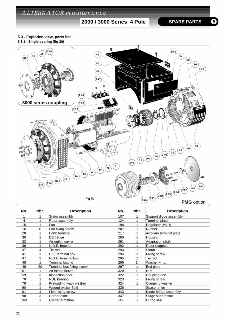
5.3 - Exploded view, parts list. 5.3.1 - Single bearing (fig 30)
SPARE PARTS 5
No. Nbr. Description No. Nbr. Description1 1 Stator assembly 107 1 Support diode assembly4 1 Rotor assembly 124 1 Terminal plate15 1 Fan 198 1 Regulator (AVR)16 6 Fan fixing screw 207 1 Rubber28 1 Earth terminal 217 1 Auxiliary terminal plate30 1 DE flange 290 1 Housing33 1 Air outlet louvre 291 1 Adaptation shaft36 1 N.D.E. bracket 292 1 Rotor magnets37 4 Tie rod 293 1 Stator41 1 D.E. terminal box 294 2 Fixing screw47 1 N.D.E. terminal box 295 1 Tie rod48 1 Terminal box lid 296 1 Washer + nut49 20 Terminal box fixing screw 297 1 End plate51 1 Air intake louvre 320 1 Hub 59 3 Inspection door 322 1 Coupling disc70 1 NDE bearing 323 - Fixing screw79 1 Preloading wavy washer 324 1 Clamping washer90 1 Wound exciter field 325 - Spacer shim91 4 Field fixing screw 343 1 Diode bridge assembly98 3 Corner plate 347 1 Surge suppressor100 1 Exciter armature 349 1 O ring seal
3000 series coupling
PMG option
ALTERNATOR maintenance 2000 / 3000 Series 4 Pole SPARE PARTS
343
349
347
7079
90
36
51
98
59
1
124
41
48
49
47
198
320
100107
91
2837
4
1530
33
- Fig 31 -
207
1615
6862
290291
292293
294295
296297
217
410
6068
63
67
23
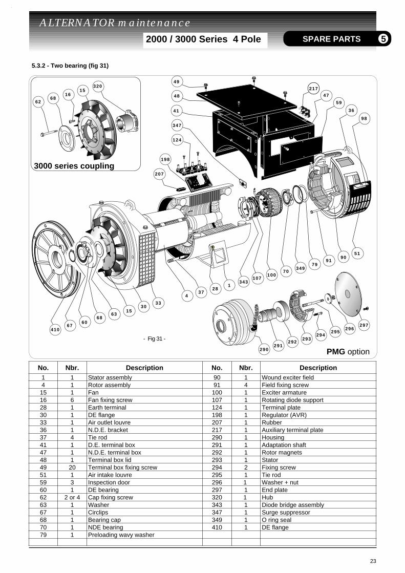
5.3.2 - Two bearing (fig 31)
5
No. Nbr. Description No. Nbr. Description1 1 Stator assembly 90 1 Wound exciter field4 1 Rotor assembly 91 4 Field fixing screw15 1 Fan 100 1 Exciter armature16 6 Fan fixing screw 107 1 Rotating diode support28 1 Earth terminal 124 1 Terminal plate30 1 DE flange 198 1 Regulator (AVR)33 1 Air outlet louvre 207 1 Rubber36 1 N.D.E. bracket 217 1 Auxiliary terminal plate37 4 Tie rod 290 1 Housing41 1 D.E. terminal box 291 1 Adaptation shaft47 1 N.D.E. terminal box 292 1 Rotor magnets48 1 Terminal box lid 293 1 Stator49 20 Terminal box fixing screw 294 2 Fixing screw51 1 Air intake louvre 295 1 Tie rod59 3 Inspection door 296 1 Washer + nut60 1 DE bearing 297 1 End plate62 2 or 4 Cap fixing screw 320 1 Hub63 1 Washer 343 1 Diode bridge assembly67 1 Circlips 347 1 Surge suppressor68 1 Bearing cap 349 1 O ring seal70 1 NDE bearing 410 1 DE flange79 1 Preloading wavy washer
3000 series coupling
PMG option