IX. DRILLING PHASE: DRILLING, CASING AND COMPLETION ... · "production casing" extends the full...
52
IX. DRILLING PHASE: DRILLING, CASING AND COMPLETION OPERATIONS A. INTRODUCTION After the well and access road have been sited and constructed, as described in the previous chapter, the operator moves in a rig and starts the drilling phase of operations. Prior to the commencement of drilling operations, a person who has been issued a drilling permit must notify by certified mail any local government and any landowner whose surface rights will be affected by drilling operations [ECL 23.0305-131. This notification is required to those whose property may be potentially affected by drilling activity and so that local jurisdictions are aware of activity taking place in their areas. Ibis notification should be required at least five business days prior to the beginning of drilling operations and local jurisdictions should be notified through the clerk of the county, city or town, and village whose land will be physically affected. DEC must be notified in writing or by telegram prior to starting actual drilling operations under the current regulatory program [6NYCRR Part 554.21. This provision is necessary so that the Department is aware of, and can monitor activity provided for in the permit as necessary. It is recommended that these regulations be revised so that notification take place a lininu of 24 hours in advance by telephone. The permit must be prominently posted at the drill site and the permit expires if drilling operations do not begin within 180 days 16NYCRR Part 552.3(c)l. It is recommended that this regulation be revised so the 180 day time period can be extended to 12 months. An effective time period for each permit is needed. If too much time elapses before drilling begins, the environmental conditions under which the permit was granted may change; however, 180 days is not sufficient in some cases for industry coordination and schedulf q!g.
Transcript of IX. DRILLING PHASE: DRILLING, CASING AND COMPLETION ... · "production casing" extends the full...

IX. DRILLING PHASE: DRILLING, CASING AND COMPLETION OPERATIONS
A. INTRODUCTION
After the well and access road have been sited and constructed, as
described in the previous chapter, the operator moves in a rig and starts the
drilling phase of operations.
Prior to the commencement of drilling operations, a person who has been
issued a drilling permit must notify by certified mail any local government
and any landowner whose surface rights will be affected by drilling operations
[ECL 23.0305-131. This notification is required to those whose property may
be potentially affected by drilling activity and so that local jurisdictions
are aware of activity taking place in their areas. Ibis notification should
be required at least five business days prior to the beginning of drilling
operations and local jurisdictions should be notified through the clerk of the
county, city or town, and village whose land will be physically affected.
DEC must be notified in writing or by telegram prior to starting actual
drilling operations under the current regulatory program [6NYCRR Part 554.21.
This provision is necessary so that the Department is aware of, and can
monitor activity provided for in the permit as necessary. It is recommended
that these regulations be revised so that notification take place a lininu of
24 hours in advance by telephone.
The permit must be prominently posted at the drill site and the permit
expires if drilling operations do not begin within 180 days 16NYCRR Part
552.3(c)l. It is recommended that this regulation be revised so the 180 day
time period can be extended to 12 months. An effective time period for each
permit is needed. If too much time elapses before drilling begins, the
environmental conditions under which the permit was granted may change;
however, 180 days is not sufficient in some cases for industry coordination
and schedulf q!g.

1. Drilling Rigs
The majority of wells in New York State are drilled with rotary rigs.
(Figure 9.1). The rig gets its name from the rotational motion of the
drilling bit which grinds through rock. Cable tool rigs are an older, less
common type of rig that chip rock to a powder by raising and dropping a heavy
bit in the bore hole. (Figure 9.2).
Rotary rigs are larger and faster than cable tool rigs and can also drill
to greater depths, yield a smoother well bore, and diminish the time water
sands are exposed to the drilling process. Cable tool rigs are sometimes
favored when there are no pressing time constraints and the operator wishes to
save money. Their use, however, is restricted to relatively shallow wells
(generally less than 2,000' ) . The remainder of this chapter focuses on rotary rig operations. However,
additional information on cable tool rigs is given when significantly
different procedures are involved and/or different regulations apply. Special
permit conditions for wells drilled through primary aquifers or in the Bass
Island trend are also explained.
2. Drilling Fluids
Drilling fluids must be used when drilling wells with a rotary rig. The
fluids are pumped down the drill string, out through holes (jets) in the drill
bit and up the wellbore. The moving fluid cools and lubricates the bit and
removes the rock cuttings that would otherwise collect at the bottom of the
wellbore.
There are four basic types of drilling fluids used in New York State:
air, freshwater, brine and mud. Operators select a drilling fluid based on:
1) its compatibility with the rock formations being drilled through, 2) need
to control downhole pressures and 3) cost. Air is the most frequently used
drilling fluid in New York State. It is fast and economical, but cannot be


FIGURE 9.2 CABLE TOOL RIG
exterior view
FIGURE 9.2
9-2b

used when excessive pressures or amounts of water are encountered. Freshwater
may be selected when air cannot provide sufficient pressure to control the
well. Air or fresh water based drilling fluid is required by the Department
when drilling through freshwater aquifers.
Brine (salt water) is sometimes employed as a drilling fluid because of
the physical and chemical characteristics of the rocks that are being drilled
through. For example, a fully saturated brine must be used when drilling
through rock salt to prevent the rock from dissolving and rapidly enlarging
the borehole.
Though drilling mud is the most common drilling fluid in the country, it
is used infrequently in New York State because it is not needed due to low
subsurface pressures. Mud ingredients are expensive and the use of mud slows
the drilling rate thereby increasing drilling cost. Mud is sometimes also
difficult to dispose of properly. In New York State, mud is generally used
only in specific instances such as spudding (starting) wells or drilling the
surface casing hole through thick shallow gravel deposits. It may also be
needed and used when unusually high formation pressures or volumes are
encountered.
The changing conditions encountered as the well gets deeper frequently
require changes in the properties of the drilling fluid. The fluid can be
altered as needed by the addition of special chemicals. These chemicals
include such things as surfactants, foaming agents, corrosion inhibitors,
weighting materials, fluid loss control additives, and bactericides.
3. Casing and Cementing
A good casing and cementing program is essential to protect groundwater
quality and provide well control. From the operator's viewpoint it is also
essential to the future production potential of the well.

Casing is heavy metal pipe that is used to prevent the borehole from
caving in. Once the casing is cemented into place it also plays an important
role in preventing fluid migration and protecting freshwater aquifers. Three
strings of casing are normally set in New York State wells. A short conductor
casing at the top of the well keeps soil, sand and gravel from sloughing into
the borehole and filling in the well. A small diameter surface casing is set
inside the conductor casing and extends beneath the deepest freshwater zone to
protect it from contamination. In some instances, an additional casing
string, called an intermediate string, is necessary because of a lost
circulation zone or other hole problems. The last string, known as
"production casing" extends the full length of the well and is used to carry
hydrocarbons from the producing horizon to the surface.
4. Drilling Safety Considerations
Injuries to oil and gas field service employees occur at about twice the
rate as for general industry employees and, of this group, oil and gas
drilling workers are exposed to even greater dangers due to the nature of this
type of work (U.S. Dept. of Health and Human Services, 1983). The Federal
Occupational Safety and Health Administration (OSHA) has proposed rig safety
regulations for drilling operations, but as yet, it does not have requirements
for routine drilling operations. Therefore, it is important for drilling
operators, in the absence of strict guidelines, to ensure that drilling
activities are conducted in a safe manner. A sound safety program helps guard
against drilling accidents which could cause environmental damage as well as
injure employees. A good safety program also has the added benefits of lower
insurance rates, lower maintenance costs, fewer employee benefits claims, less
lost production or productivity, and fewer legal fees and settlements.
Some of the most common accidents associated with drilling have to do
with working the slips, tongs, catlines, and elevators which are used to

handle the drill pipe, and other heavy drilling equipment. Slippery rig
floors and cable breaks also contribute to accidents. Injuries to the
derrickman are common either from falling or being hit by swinging objects.
Uncommon accidents include catastrophic events such as blowouts or the
collapse of the derrick or mast.
Employee training programs are an important component of accident
prevention. Accidents are also reduced when employees are trained properly,
well oriented, motivated and retained to become career oil field staff.
Training of staff should include information about basic principles of a well
drilling operation: 1) the safe work operations and hazards associated with
the job. 2) purpose and operation of drilling equipment, 3) Hydrogen sulfide
detection and safety equipment as well as emergency procedures, 4) fire
protection and control, 5 ) emergency escape procedures for employees working
on the derrick mast or in confined spaces, and 6) information about personal
protective equipment.
Many drilling sites are located in rural areas of New York. Therefore,
it is advisable to post first aid and emergency procedure information in a
conspicuous place should these be needed in the case of an accident. First
aid equipment, appropriate telephone and/or radio numbers, an arm and leg
splint, a heavy blanket and a stretcher are recommended to be on hand in case
of an emergency.
Employee clothing should be well fitted (not loose) and include long
sleeves and pant legs. It is also advisable that employees not wear jewelry,
that hair be short or tied-back, and safety shoes, hard hats, goggles, face
shields for welding, safety glasses and/or hearing protection be worn as
needed. Employee protection against falls also needs attention. Measures such
as safety belts, lifelines and lanyards of suitable strength, safety nets for

work areas more than 25' off the ground and ladders in place of "riding"
climbing devices should be installed to safeguard workers in the event of a
fall.
Precautionary measures for the drill site would include proper lighting
for working at night, and the prohibition of flame heaters in doghouses or
outbuildings. Drill sites need to have no-smoking area designations and fire
and explosion protection equipment. Pirefighting equipment needs to be on
hand. DEC currently requires a blowout prevention plan from all operators in
the Bass Island trend. Responsibilities of individual employees in such an
event are to be posted in the doghouse. In addition, the local fire
department must be called in the event of a blowout. It is also recommended
that operators make regular operating tests of blowout preventers and conduct
U c k response training in order to be prepared in the case of an accident.
mere blowout preventers are required, they should be actuated and tested
with rig air or another approved method before drilling out the shoe of the
surface casing.
Other precautionary measures to guard against fires or other accidents
include proper grounding of derricks or masts, electric cords and receptacles
from lightning and static electricity, use of appropriate containers and
portable tanks for handling combustible liquids, use of cleaning materials
that have a flash point greater than 100eF, and locating fuel storage tanks
some distance, such as 50' to 75', from a wellbore.
Routine inspections, testing and maintenance of rig components also help
avoid accidents from drilling operations. Daily inspections should include
all functional operating mechanisms, the drill string weight indicator, air or
hydraulic system parts for deterioration or leakage, bending of hooks, hoist
or load attachment chains, rope slings, and rope reeving. Periodic
inspections should also be conducted of bails, elevator links, upper side hook

saddles, A-leg pins, housing, and hoisting mechanisms. Drilling equipment
tests might include load tests of repaired or altered rigs, and operating
tests of new and/or altered hoisting equipment. Adjustments and repairs
should be done promptly and equipment maintained to the manufacturer's
specifications.
The Department's regulatory program addresses some safety concerns.
These are primarily oriented towards oil wells and operations. The existing
regulations require the following:
a. The operation of any well, lease or unit shall be such as to keep
each well location and unit installation free of rubbish, debris,
dead grass, brush, weeds, and other flammable material. In
addition, all waste oil shall be disposed of in a manner which will
not create a fire hazard [6NYCRR Part 556.4(b)1.
b. At the Department's requirement when it deems it necessary to
protect life, health, or property, the owner or operator must
construct around any storage tank or other tank an earthen dike
having a capacity of at least one and one-half times the capacity of
of the tank it surrounds. This dike must be continuously
maintained; and the reservoir it creates must be kept free of
vegetation and water [Part 556.4(c)I.
c. At any time when oil or gas is lost from wells or pipelines.
receiving tanks, storage tanks or receiving and storage receptacles
and creates a fire or pollution hazard or exceeds 100 barrels of oil
in aggregate, or 3 million cubic feet of gas in aggregate, the DEC
regional headquarters must be notified within five days after the
event. A report of remedial measures being taken to correct the
situation must also be given to DEC 16NYCRR Part 556.4Cd)l.
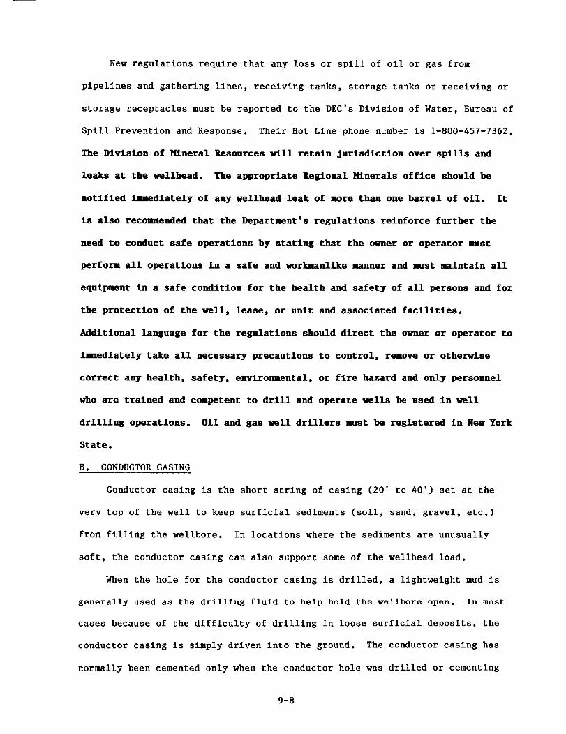
New regulations require that any loss or spill of oil or gas from
pipelines and gathering lines, receiving tanks, storage tanks or receiving or
storage receptacles must be reported to the DEC's Division of Water, Bureau of
Spill Prevention and Response. Their Hot Line phone number is 1-800-457-7362.
The Division of ntneral Resources vlll retain jurisdiction over spills and
leaks at the wellhead. The appropriate Regional ntnerals office should be
notified irrediately of any wellhead leak of more than one barrel of oil. It
is also recoomended that the Department's regulations reinforce further the
need to conduct safe operations by stating that the owner or operator rust
perform all operations in a safe and vorloanlike manner and m s t maintain all
equipment in a safe condition for the health and safety of all persons and for
the protection of the well, lease, or unit and associated facilities.
Additional language for the regulations should direct the owner or operator to
immediately take all necessary precautions to control, remove or otherwise
correct any health, safety, environmental, or fire hazard and only personnel
who are trained and competent to drill and operate wells be used in well
drilling operations. Oil and gas well drillers rust be registered in Mew York
State.
B. CONDUCTOR CASING
Conductor casing is the short string of casing (20' to 40') set at the
very top of the well to keep surficial sediments (soil, sand, gravel, etc.)
from filling the wellbore. In locations where the sediments are unusually
soft, the conductor casing can also support some of the wellhead load.
When the hole for the conductor casing is drilled, a lightweight mud is
generally used as the drilling fluid to help hold the wellbore open. In most
cases because of the difficulty of drilling in loose surficial deposits, the
conductor casing is simply driven into the ground. The conductor casing has
normally been cemented only when the conductor hole was drilled or cementing

was requi red a s a permit condit ion. The genera l p r a c t i c e of d r i v i n g cas ing
i n t o t h e ground leaves l i t t l e c learance f o r cement between t h e pipe and t h e
ma te r i a l it penet ra tes . Since February 6 , 1985, however, ope ra to r s using a
conductor s t r i n g i n primary aqu i fe r s , have been required t o cement t h e
conductor cas ing t o prevent t h e poss ib l e downward flow of p o l l u t a n t s , along
t h e outs ide of t h e cas ing t o freshwater zones.
I f t h e conductor cas ing i s s e t i n a d r i l l e d hole , i t must be cemented i n
p lace before d r i l l i n g can continue. The opera tor must c a l c u l a t e t h e amount of
cement needed t o f i l l t h e space between t h e conductor casing and borehole wal l
and use a t l e a s t t h a t amount i n t h e cementing Job. For we l l s d r i l l e d i n
p r i n c i p a l and primary a q u i f e r s , opera tors a r e requi red t o use a c a l c u l a t e d 50
percent excess i n cementing t h e conductor cas ing . I f c i r c u l a t i o n t o t h e
su r face i s not achieved, even with t h e excess cement, then t h e opera tor must
g rout cement down from t h e su r face t o achieve a complete cement bond.
Grouting i s done by i n s e r t i n g a t h i n p iece of tubing known a s t h e macaroni o r
spaghe t t i s t r i n g between t h e borehole and t h e ou t s ide of t h e conductor casing.
Cement is pumped through t h e s t r i n g u n t i l t h e space i s f i l l e d wi th cement.
When the conductor cas ing is d r iven and t h e r e is no c learance around t h e
ou t s ide of t h e pipe, t h e opera tor mus t grout from t h e top of t h e cas ing t o
form a p ro tec t ive cement pad around the conductor i f t h i s cas ing s t r i n g i s not
recovered when su r face pipe is run. The pad m u s t have a minimum diameter of
t h ree f e e t , minimum th ickness of s i x inches a t t h e cas ing and a minimum
th ickness of four inches a t t h e ou te r rad ius . The pad m u s t a l s o s lope away
from t h e cas ing i n a l l d i r e c t i o n s t o f u r t h e r ensure t h a t su r face p o l l u t a n t s do
not e n t e r t h e subsurface a t t h e top of t h e conductor casing.
D r i l l i n g of t h e we l l below t h e conductor cas ing cannot resume u n t i l t h e
cement has been allowed t o s e t . Operators usua l ly wait 8 t o 10 hours f o r the

cement to harden, though the process can be accelerated with special
additives. Depending on weather conditions, 8 to 10 hours may be insufficient
to harden. Failure to wait until the cement is dry can disrupt the bond
between the cement and the casing and provide a conduit for pollutants.
C. SURFACE CASING
The primary functions of the surface casing are to provide an anchor for
well control equipment, prevent water zones from flooding the wellbore and
protect freshwater zones from contamination by gas, oil, brine, drilling fluid
or any other substances that may be present in the wellbore (Figure 9.3).
Operators must cement enough surface casing to contain any pressure on the
blowout prevention equipment that may be encountered further downhole. This
requires that the surface casing be set into competent bedrock. Existing
statewide casing regulations adopted in 1966 require that casing be set below
the deepest potable freshwater level [6NYCRR 554.4(b)]. The length of the
surface casing is generally between 300' and 500', though a survey of Well
Completion Reports shows Individual instances of shorter as well as longer
casing lengths.
Cement in the annular space around the surface casing restricts the
movement of fluids between formations as well as between formations and the
surface. In terms of protecting groundwater resources, adequate annular
cement jobs help prevent the contamination of fresh groundwaters.
Most operators run surface casing in their wells. However, current
regulations allow them to eliminate the surface casing if the production
casing is cemented from total depth to the top of the well in areas where the
pressure characteristics of the subsurface formations have been reasonably
well established by prior drilling experience [6NYCRR 554.4(a)1. With the
exception of the Bass Island trend, which wasn't discovered until 1981, the
producing formations in New York State are generally well known and have low

FIGURE 9.3 PRIMARY CEMENTING PROCEDURES
Cementing a well helps accomplish the fallowing:
RCM CrnwMp UM
FiO.1 Collar
Job In Process Job Flnlahed
o Bonds and supports the casing. o Protects casing from corrosion due to subsurface mineral waters and
o Restricts fluid movement between electrolysis from the outside. formations, e.g., t o prevent contamination of fresh water zones o ?rotects casing from shock loads by hydrocarbons or salt water. when drilling deeper.
,
o Seals lost circulation or thief zones.
*figare taken from paper by Charles George. Ronald Paul. Rallibvcton Services. Duncan, Oklahoma - Cementing Iechnlques far Solution tuning Yells and Salt Storage Domes: The State-of-the Art - Smposium Proceedings Salts and Brines '85 .
FIGURE 9.3 9-10a
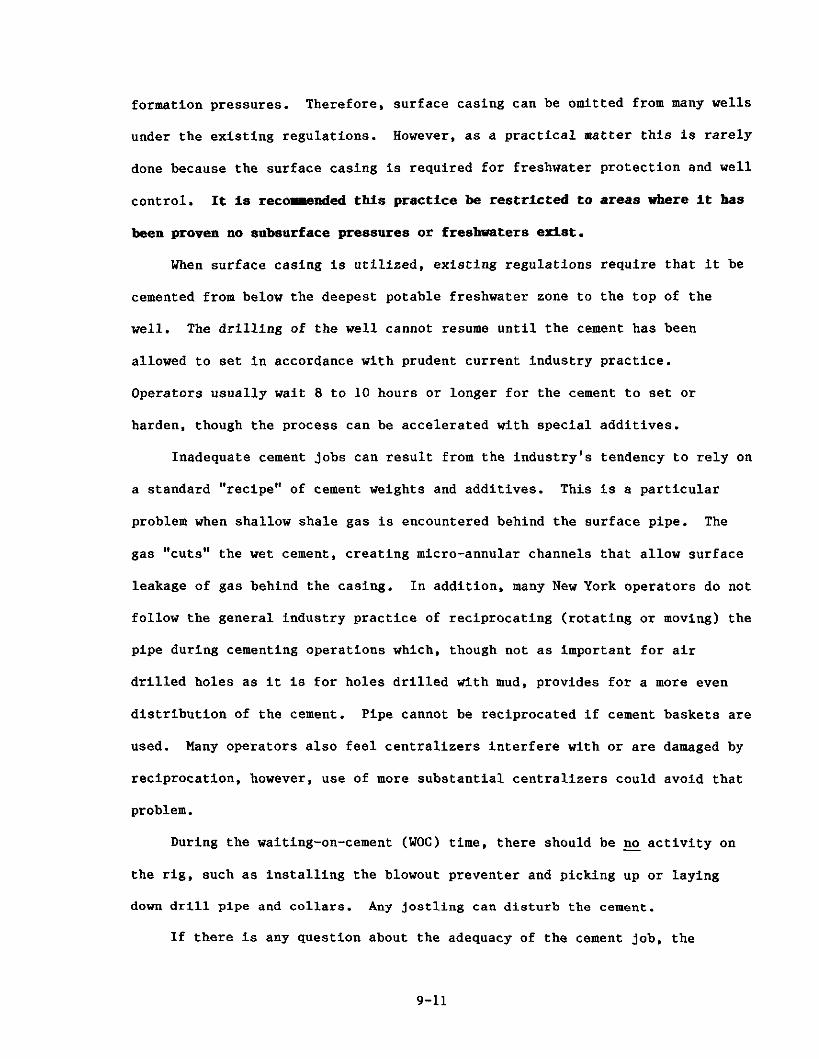
formation pressures. Therefore, surface casing can be omitted from many wells
under the existing regulations. However, as a practical matter this is rarely
done because the surface casing is required for freshwater protection and well
control. It is reco-nded this practice be restricted to areas where it has
been proven no subsurface pressures or freshwaters exist.
When surface casing is utilized, existing regulations require that it be
cemented from below the deepest potable freshwater zone to the top of the
well. The drilling of the well cannot resume until the cement has been
allowed to set in accordance with prudent current industry practice.
Operators usually wait 8 to 10 hours or longer for the cement to set or
harden, though the process can be accelerated with special additives.
Inadequate cement jobs can result from the industry's tendency to rely on
a standard "recipe" of cement weights and additives. This is a particular
problem when shallow shale gas is encountered behind the surface pipe. The
11 gas cuts" the wet cement, creating micro-annular channels that allow surface
leakage of gas behind the casing. In addition, many New York operators do not
follow the general industry practice of reciprocating (rotating or moving) the
pipe during cementing operations which, though not as important for air
drilled holes as it is for holes drilled with mud, provides for a more even
distribution of the cement. Pipe cannot be reciprocated if cement baskets are
used. Many operators also feel centralizers interfere with or are damaged by
reciprocation, however, use of more substantial centralizers could avoid that
problem.
During the waiting-on-cement (WOC) time, there should be no activity on
the rig, such as installing the blowout preventer and picking up or laying
down drill pipe and collars. Any jostling can disturb the cement.
If there is any question about the adequacy of the cement job, the

operator may be required to run a temperature and/or cement bond log and/or do
expensive remedial work. The order to run the log may be given by the State
Inspector present during the cementing operations or during a routine well
drilling site inspection. Site inspections are conducted at least once during
the drilling of every well to determine if all the conditions of the permit
are being followed. The inspections usually occur after the surface casing is
set but before the production string is cemented except in primary or
principal aquifers where inspectors are required to be on location during the
cementing job on the surface casing. Inspection staff pay particular
attention to the depth of the surface pipe and whether cement circulation was
achieved. They also check the wellbore diameters listed on the driller's
records. This information will be required for every well when a new version
of the Completion Report Form is issued in the near future. It is needed to
compare the size of the annular space against the number of sacks of cement
used to seal it off.
Since November, 1982, operators drilling in primary aquifers have had to
comply with detailed surface casing requirements. An 8 518" freshwater string
(surface casing) had to be set a minimum of 450'. or 100' into bedrock,
whichever was greater. The cement for the surface casing had to be circulated
back to the surface using a calculated 50 percent excess and the casing had to
have a minimum bursting pressure of 1,800 psi. A State Inspector had to be
present during the surface casing cementing operation and the cement had to
contain lost circulation material to help ensure adequate cementing results.
A minimum of two cement baskets and centralizers had to be run at appropriate
intervals during the surface casing cement jobs to help guarantee a sound
cement job. Centralizers center the casing in the wellbore and cement baskets
are used where the weight of the cement column might break-down the formation.
The Bass Island permit conditions also require cement baskets and centralizers

for cementing the surface casing but specify only that an "appropriate" number
of them be used.
In the event cement circulation is not achieved, cement has to be grouted
down from the surface (or squeezed) to form a complete cement bond around the
casing.
1. Recent Revisions
As a result of public comments made at a hearing on December 19, 1984,
the casing and cementing requirements in the aquifer permit conditions were
revised in February, 1985. The changes will remain in effect until the final
Generic Environmental Impact Statement (GEIS) on Oil, Gas and Solution Mining
is published. After the EIS has been reviewed and comments have been
received, the Department will decide whether the revisions should be retained
as is or whether other aquifer permit conditions are needed.
As of February, 1985, the 450' specification on the permit conditions has
been dropped and all surface casing in primary and principal aquifers must be
set a minimum of 100' into bedrock unless shallow gas is present. The pipe
used for the surface casing must be either new API graded pipe with a minimum
burst pressure of 1,800 psi or reconditioned pipe that has been tested to
2,700 psi. If reconditioned pipe is used, an affidavit that the pipe has been
tested must be submitted to the State Inspector before the pipe is run. The
length of the advance notice given the Department prior to cementing the
surface casing has been increased from 4 to 8 hours and the permit condition
has been reworded to stress that the cementing may not commence until a State
Inspector is present.
2. Further Revisions
The Department has significantly strengthened its regulatory requirements
for oil and gas wells drilled in primary and principal aquifers, but potable

groundwater, outside of the major aquifers, is found throughout the State.
Over two million people in upstate New York are served by private water
wells and many of these wells are in small isolated or bedrock aquifers (NYS
DEC Division of Water, 1985). Because of numerous complaints involving oil
and gas in water wells in these areas, the Department has made an extensive
review of existing cementing and casing practices for both oil and gas wells.
In the review on drilling and completion practices for oil and gas wells,
the Department found some drilling and completion practices deficient with
respect to long-term protection of groundwater with a high degree of
certainty.
The revised casing and cementing guidelines are designed to mitigate and
alleviate the following problems:
1. potential gas and fluid migration into groundwater;
2. gas channeling through cemented annuli;
3. migration of fluids from one stratum to another;
4. repressurization of old oil field areas by natural gas wells drilled
to deeper horizons; and
5 . ensuring the long-term integrity of oil and injection well
completions to preclude future problems.
The new cementing guidelines were implemented April 1, 1986.
SURFACE CASING - -- 1. The diameter of the drilled surface hole shall be large enough to
allow running of centralizers in recommended hole sizes.
2. Surface casing shall extend at least 75 feet beyond the deepest fresh water zone encountered or 75 feet into competent rock (bedrock), whichever is deeper. However, the surface pipe must be set deeply enough to allow the BOP stack to contain any formation pressures that may be encountered before the next casing is run.
3. Surface casing shall not extend into zones known to contain measurable quantities of shallow gas. In the event that such a zone is encountered before the fresh water is cased off, the operator shall notify the
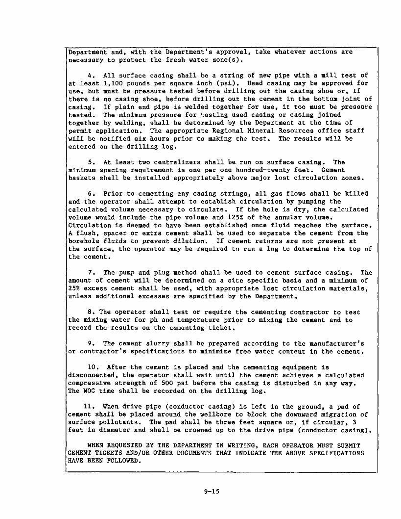
Department and, with the Department's approval, take whatever actions are necessary to protect the fresh water zone(s).
4. All surface casing shall be a string of new pipe with a mill test of at least 1,100 pounds per square inch (psi). Used casing may be approved for use, but must be pressure tested before drilling out the casing shoe or, if there is no casing shoe, before drilling out the cement in the bottom joint of casing. If plain end pipe is welded together for use, it too must be pressure tested. The minimum pressure for testing used casing or casing joined together by welding, shall be determined by the Department at the time of permit application. The appropriate Regional Mineral Resources office staff will be notified six hours prior to making the test. The results will be entered on the drilling log.
5. At least two centralizers shall be run on surface casing. The minimum spacing requirement is one per one hundred-twenty feet. Cement baskets shall be installed appropriately above major lost circulation zones.
6. Prior to cementing any casing strings, all gas flows shall be killed and the operator shall attempt to establish circulation by pumping the calculated volume necessary to circulate. If the hole is dry, the calculated volume would include the pipe volume and 125% of the annular volume. Circulation is deemed to have been established once fluid reaches the surface. A flush, spacer or extra cement shall be used to separate the cement from the borehole fluids to prevent dilution. If cement returns are not present at the surface, the operator may be required to run a log to determine the top of the cement.
7. The pump and plug method shall be used to cement surface casing. The amount of cement will-be determined on a site specific basis and a minimum of 25% excess cement shall be used, with appropriate lost circulation materials, unless additional excesses are specified by the Department.
8. The operator shall test or require the cementing contractor to test the mixing water for ph and temperature prior to mixing the cement and to record the results on the cementing ticket.
9. The cement slurry shall be prepared according to the manufacturer's or contractor's specifications to minimize free water content in the cement.
10. After the cement is placed and the cementing equipment is disconnected, the operator shall wait until the cement achieves a calculated compressive strength of 500 psi before the casing is disturbed in any way. The WOC time shall be recorded on the drilling log.
11. When drive pipe (conductor casing) is left in the ground, a pad of cement shall be placed around the wellbore to block the downward migration of surface pollutants. The pad shall be three feet square or, if circular, 3 feet in diameter and shall be crowned up to the drive pipe (conductor casing).
WHEN REQUESTED BY THE DEPARTMENT IN WRITING, EACH OPERATOR MUST SUBMIT CEMENT TICKETS AND/OR OTHER DOCUMENTS THAT INDICATE THE ABOVE SPECIFICATIONS HAVE BEEN FOLLOWED.

THE CASING AND CEMENTING PRACTICES ABOVE ARE DESIGNED FOR TYPICAL SURFACE CASING CENENTINGS. THE DEPARTMENT WILL REQUIRE ADDITIONAL MEASURES FOR WELLS DRILLED IN ENVIRONMENTALLY OR TECHNICALLY SENSITIVE AREAS (I.E. PRIMARY OR PRINCIPAL AQUIFERS).
THE DEPARTMENT RECOGNIZES THAT VARIATIONS TO THE ABOVE PROCEDURES MAY BE INDICATED IN SITE SPECIFIC INSTANCES. SUCH VARIATIONS WILL REQUIRE THE PRIOR APPROVAL OF THE REGIONAL MINERAL RESOURCES OFFICE STAFF.
INTERMEDIATE CASING
Intermediate casing string(s) and the cementing requirements for that casing string(s) will be reviewed and approved by Regional Mineral Resources office staff on an individual well basis.
PRODUCTION CASING
12. The production casing cement shall extend at least 500 feet above the casing shoe or tie into the previous casing string, whichever is less. If any oil or gas shows are encountered or known to be present in the area, as determined by the Department at the time of permit application, or subsequently encountered during drilling, the production casing cement shall extend at least 100 feet above any such shows. The Department may allow the use of a weighted fluid in the annulus to prevent gas migration in specific instances when the weight of the cement column could be a problem.
13. Centralizers shall be placed at the base and at the top of the production interval if casing is run and extends through that interval, with one additional centralizer every 300 feet of the cemented interval. A minimum of 25% excess cement shall be used. When caliper logs are run, a 10% excess will suffice. Additional excesses may be required by the Department in certain areas.
14. The pump and plug method shall be used for all production casing cement jobs deeper than 1500 feet. If the pump and plug technique is not used (less than 1500 feet), the operator shall not displace the cement closer than 35 feet above the bottom of the casing. If plugs are used, the plug catcher shall be placed at the top of the lowest (deepest) full joint of casing.
15. The casing shall be of sufficient strength to contain any expected formation or stimulation pressures.
16. Following cementing and removal of cementing equipment, the operator shall wait until a compressive strength of 500 psi is achieved before the casing is disturbed in any way. The operator shall test or require the cementing contractor to test the mixing water for ph and temperature prior to mixing the cement and to record the results on the cementing ticket and/or the drilling log. WOC time shall be adjusted based on the results of the test.
17. The annular space between the surface casing and the production string shall be vented at all times. If the annular gas is to be produced, a pressure relief valve shall be installed in an appropriate manner and set at a pressure approved by Regional Mineral Resources office staff.

WHEN REQUESTED BY THE DEPARTMENT IN WRITING. EACH OPERATOR MUST SUBMIT CEMENT TICKETS AND/OR OTHER DOCUMENTS THAT INDICATE THE ABOVE SPECIFICATIONS HAVE BEEN FOLLOWED.
THE CASING AND CEMENTING PRACTICES ABOVE ARE DESIGNED FOR TYPICAL PRODUCTION CASING CEMENTINGS. THE DEPARTMENT WILL REQUIRE ADDITIONAL MEASURES FOR WELLS DRILLED IN ENVIRONMENTALLY OR TECHNICALLY SENSITIVE AREAS (I.E. PRIMARY OR PRINCIPAL AQUIFERS).
THE DEPARTMENT RECOGNIZES THAT VARIATIONS TO THE ABOVE PROCEDURES MAY BE INDICATED IN SITE SPECIFIC INSTANCES. SUCH VARIATIONS WILL REQUIRE THE PRIOR APPROVAL OF THE REGIONAL MINERAL RESOURCES OFFICE STAFF.
I RECOMMENDED CENTRALIZER-HOLE SIZE COMBINATIONS
Centralizer Size Minimum Hole Size Minimum Clearance Inches Inches Inches
Note: (1) If a manufacturer's specifications call for a larger hole size than indicated in the above table, then the manufacturers specs take precedence.
(2) Check with appropriate regional office for sizes not listed above.
When a well has surface casing that is set at the proper depth and the
above guidelines are followed, the only impacts that might occur from drilling
in very close proximity to a waterwell are turbidity and temporary loss of the
supply. Turbidity and water supply disruption can occur while drilling the
surface hole before the protective surface casing is set. When an aquifer is
penetrated, the disturbance allows unconsolidated sediments to enter a water
suppl) and create offset turbidity, but only if a subsurface channel of

sufficient porosity and permeability in close proximity is present.
If the surface hole is drilled with the proper drilling fluid, a
filtercake will develop and isolate the wellbore. With a filtercake, only
minor turbidity a maximum of few feet into a permeable aquifer could occur
from the infiltration of the drilling fluid. Cement can also filtrate into
permeable aquifer zones if adequate lost circulation material is not used
during cementing operations. The majority of these situations are temporary,
and ususally correct themselves in a short time. In isolated cases, uncased
water wells can cave-in or permeable water channels can be intercepted and re-
routed, adversely affecting a water well's quality and quantity of water. In
rare cases, the drilling of a new water well may be required.
D. WELL CONTROL
A blowout is an uncontrolled intrusion of fluid (oil, gas, water) under
high pressure into the wellbore. The ability of casing to withstand pressure
is affected by the grade of steel, thickness of the casing and the setting
depth. The casing must be able to withstand unexpected high pressure
formations or a pressure kick and the high pressure surges encountered when a
well is shut-in to control a threatened well blowout.
1. Blowout Preventers
Blowout preventers (BOP'S) have been required since September 1982 on all
wells drilled in New York State. Exceptions are granted only if the operator
submits a written request for a waiver showing that: 1) the well is not a
rank wildcat, 2) the well is neither in or near the Bass Island trend, 3 )
there has been no prior history of blowouts within a one mile radius, 4) some
sort of pressure diverting device will be used on the well to control high
pressures. A waiver is never given to wells drilled under aquifer permit
conditions.

Blowout preventers are manually or hydraulically operated devices
installed at the top of the surface casing to seal off fluids coming up the
wellbore. (See Figure 9.4). Within the blowout preventer there may be a
combination of different types of sealing devices. Pipe rams contain two
metal blocks with semi-circular notches that fit together around the outside
of the drill pipe when it is in the hole. Blind rams contain two rubberfaced
metal blocks that can completely seal off the hole when there is no drill pipe
in it. Annular or "bag" blowout preventers contain a resilient packing
element which expands inward to seal off the hole with or without drill pipe.
Each BOP assembly must contain 1) both blind and pipe rams or 2) a bag or
annular preventer, so it can function effectively with or without drill pipe
in the hole.
The BOP is flanged and bolted to the spool which is flanged and bolted
to the casinghead. The casinghead is welded to the top of the surface casing.
If this weld or any other connections in the BOP stack are not sound, the BOP
system can fail, resulting in loss of well control, possible damage to the
rig, fire and/or loss of life.
To ensure that the BOP will be ready in any emergency, the Bass Island
permit conditions stipulate that the BOP cannot be dependent on rig hydraulics
for its actuation energy source. If the rig power system fails or the rig
area is too dangerous to enter, the BOP can then be operated from a separate
power source a safe distance away.
In the Bass Island trend all of the control lines connected to the BOP
must be made of high pressure tubular steel with flanged connections. All
BOPS have both a choke line and a kill line. The choke line goes to the choke
manifold which is an assembly of high pressure flanged pipe fittings with
several lateral outlets controlled by manual and/or automatic valves. When
activated, the choke manifold assists in maintaining sufficient back pressure

FIGURE 9.4 BLOWOUT PREVENTION EQUIPMENT
Annular Preventer
Blowout prevention equipment is placed at the top of the well casing and includes one or more devices for closing off the well. Typical examples are:
Annular preventers - equipment containing a packing element which. when activated, will extend into the well-bore and around the drillpipe to form a pressure-tight seal. These are usually used when pipe is in the hole.
Blind rams - a closure mechanism containing two metal blocks which can be closed together hydraulically to seal off the hole. These are usually used when no pipe is in the hole. Blind rams can seal with pipe in the hole by crushing the pipe.
Pipe rams - are similar to blind rams except the metal blocks contain semi-circular notches on the closing edges so that, when the rams are drawn together, they fit around the drillpipe to seal off the well. Pipe.rams are used when pipe is left in the hole.
FIGURE 9.4
9-l9a

i n t h e wellbore t o prevent any f u r t h e r formation f l u i d in t rus ion . The we l l
f l u i d can then be d ive r t ed from the BOP s t ack t o the reserve p i t o r t h e mud
condit ioning a rea thus r e l i e v i n g wellbore pressure. This allows t h e operator
t o pump k i l l f l u i d (heavy f l u i d t o hold the we l l pressure) i n t o t h e wellbore.
The l i n e t h a t d i v e r t s f l u i d s t o the p i t i s known a s the flow o r "blooie" l i n e .
I n t h e Bass I s l and t rend, the b looie l i n e must be constructed of T + C ( thread
and c o l l a r ) t ubu la r goods with a working pressure of a t l e a s t 1,500 ps i . I n
addi t ion , t h e choke l i n e connection t o the wellhead mus t be flanged f o r e x t r a
s t r eng th . The Bass Is land condi t ions were placed i n f i n a l regula t ions May,
1986.
During the wel l d r i l l i n g s i t e inspect ions conducted on every wel l , DEC
s t a f f rou t ine ly check whether a blowout preventer i s i n place i f required.
They a l s o check t o make su re t h e flow o r b looie l i n e is secured t o keep it
from whipping around o r dismantl ing i n t h e event of a k ick (pressure surge).
On Bass Is land we l l s t h e pipes and l i n e s must be s taked and chained down
because of the high pressures o r volumes t h a t could be encountered i n
d r i l l i n g .
The choke manifold assembly on we l l s i n the Bass Is land t rend must be
flanged and i n s t a l l e d no l e s s than 25 f e e t from the wellhead. The setback i s
required t o a l low the crew t o continue t o use the manifold when the r i g a rea
i t s e l f i s not s a f e . To he lp s a f e l y c o n t r o l the k ick o r blowout, t h e choke
manifold assembly cannot conta in elbows o r T ' s i n i ts l i n e s , e i t h e r a t t he
wellhead, o r before t h e choke. The choke l i n e must a l s o be welded from the
f lange spool t o t h e choke assembly. Cer t a in threaded, flanged and bol ted
connections a r e a l s o allowed but t h e Department w i l l not accept d res se r
s leeves .
The k i l l l i n e extends from the mud pumps t o t h e BOP s t ack and is usua l ly
a t tached t o t h e BOP d i r e c t l y opposi te the choke l i n e . I n the event of a k ick
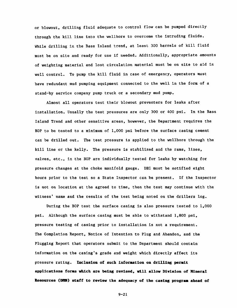
or blowout, drilling fluid adequate to control flow can be pumped directly
through the kill line into the wellbore to overcome the intruding fluids.
While drilling in the Bass Island trend, at least 300 barrels of kill fluid
must be on site and ready for use if needed. Additionally, appropriate amounts
of weighting material and lost circulation material must be on site to aid in
well control. To pump the kill fluid in case of emergency, operators must
have redundant mud pumping equipment connected to the well in the form of a
stand-by service company pump truck or a secondary mud pump.
Almost all operators test their blowout preventers for leaks after
installation. Usually the test pressures are only 300 or 400 psi. In the Bass
Island Trend and other sensitive areas, however, the Department requires the
BOP to be tested to a minimum of 1,000 psi before the surface casing cement
can be drilled out. The test pressure is applied to the wellbore through the
kill line or the kelly. The pressure is stabilized and the rams, lines,
valves, etc., in the BOP are individually tested for leaks by watching for
pressure changes at the choke manifold gauge. DEC must be notified eight
hours prior to the test so a State Inspector can be present. If the Inspector
is not on location at the agreed to time, then the test may continue with the
witness' name and the results of the test being noted on the drillers log.
During the BOP test the surface casing is also pressure tested to 1,000
psi. Although the surface casing must be able to withstand 1,800 psi,
pressure testing of casing prior to installation is not a requirement.
The Completion Report, Notice of Intention to Plug and Abandon, and the
Plugging Report that operators submit to the Department should contain
information on the casing's grade and weight which directly affect its
pressure rating. Inclusion of such infomation on drilling permit
applications forms which are being revised, vill a l l w Mrision of Mineral
Resources (W) staff to review the adequacy of the casing program ahead of

time and require changes i f needed.
E. PRODUCTION CASING
A third string of casing is often set in the well for gas or oil to flow
through. It is generally about 4 1 / 2 " in diameter and 1,000' to 4,500' long.
depending on the depth of the well. The production hole is usually drilled on
air instead of water. Air drilling is generally preferred by operators
because it is faster, cheaper and produces smaller quantities of waste. In
addition, some oil and gas formations are water sensitive and their producing
capabilities can be damaged by contact with water.
While drilling the production hole in Bass Island wells, operators are
required to take a number of special precautions because of the potential for
relatively high pressures and volumes that have caused a number of blowouts in
the past. Host productive areas and formations in New York State have lower
than normal (defined as hydrostatic) subsurface pressures. The operator must
provide the drilling company with a well prognosis indicating where problem
formations such as the high pressure Onondaga may occur, with appropriate
warning comments and a listing of emergency duties. Prior to penetrating the
Onondaga and associated fractured and faulted formations, the driller must
install a new air head rubber in the rotating head. The air head rubber is a
device that seals the wellhead at the spool. The rubber, which prevents
leakage of gas up the casing, can wear out as the well is drilled. Prior to
penetrating the Onondaga, the local fire department must also be notified of
the well's location and the potential hazards involved. This requirement can
be waived if the company has its own DEC approved firefighting equipment and
personnel on standby. To help decrease chances for accidents, every effort
must be made to penetrate the Onondaga during daylight hours. In addition.
the operator or his designated representative must be on site during the

penetration of the Onondaga to handle any problems that may arise.
Operators are required to cement the production casing in all wells to a
sufficient height above the production zone to prevent any movement of oil,
gas or other fluids around the exterior of the casing [6NYCRR Part 554.4(d)].
Compliance with this regulation is generally achieved by cementing the casing
from the bottom to 100' above the production zone, though exceptions to this
are known. Some operators cement the production string from top to bottom as
a standard practice.
Wells drilled in the Bass Island trend that are completed in the Medina
instead of the Onondaga formation (several hundred feet above the Medina) also
have more of their production casing cemented. If there are no hydrocarbon
shows in or above the Onondaga and its associated fault zones, the production
casing must be cemented back a minimum of 100' above the Onondaga. However,
if hydrocarbon shows are encountered, this minimum is increased to 300'.
1. Annular Pressure
Because of high annular pressures exhibited by many wells drilled in the
Jslestown Aquifer area and the difficulty of monitoring annular pressures, it
is proposed that all future oil and gas wells in primary and principal
aquifers be cemented from total depth to the surface. In special cases where
extensive surface or intermediate casing is set below the required depth,
permission may be granted to cement the production casing 50 feet into the
surface casing or intermediate string instead of to the surface. Division
personnel have had several meetings with service companies, operators, and the
Oil, Gas and Solution Advisory Mining Board to formulate cementing procedures
and guidelines that will mitigate this problem. It is now required that all
existing aquifer wells be vented or produced with limited back pressure so as
to not break down the formation at the shoe of the surface (freshwater
protection) casing. The Department may approve in some areas annular

production of shale gases with an annular pressure relief valve set below
hydrostatic pressure.
2. Complet-f~n and Test_i_&s
After the casing is set, the well must be completed. Prior to completion
the well may be stimulated and production tested.
Generally some kind of production test is made to determine the
productivity of a well. There are various kinds of tests made such as drill-
stem tests, bottom-hole pressure tests, potential tests and productivity
tests. For a drill-stem test, special tools are run into the well on the
drill pipe. Packers isolate the zone to be tested and fluids from the zone
flow through the testing (recording) tools into the drill pipe where they are
trapped by a system of valves. The fluid sample and recording devices are
then withdrawn from the well for examination. The bottom-hole pressure test
measures the pressure in the production zone when a specially designed
pressure gauge is lowered into the well. A potential test is a measurement of
the oil, water and/or gas a well will produce in a 24 hour period under fixed
conditions. A productivity test determines the effects of different flow
rates on the flowing bottom-hole pressure. The well is produced at several
rates and at each rate the bottom-hole pressure is measured.
Sometimes an extensive testing program is conducted prior to completing
a well to production. This is especially true for wildcat wells. As many as
20 or 30 zone tests may be conducted on a wildcat well. The testing and
evaluation time may take several months and may involve alternate stimulation
and testing. Flaring may also be allowed upon approval of the Regional
Minerals Manager. It is reconended that notification of the Regional D m
manager be required prior to any significant changes or time extensions of the
originally proposed well testing program, and approval of revisions to the
permanent wellbore configuration (casing and c e ~ n t ) proposed in the drilling

permit application is required.
Open hole completions are the simplest. Instead of running the full
length of the wellbore, the production casing is set just above the producing
formation. Open hole completions cost less but can present problems. The
production interval is much more difficult to selectively stimulate, excessive
gas or water production can be difficult to control, and the well may require
more frequent clean-outs.
In most new wells in New York State the casing extends the full length of
the well and the casing is perforated across the producing zone(s). The holes
in the production casing are made with a perforating "gun" that is lowered
down the well to the producing zone. The gun pierces the casing with bullets
or special shaped explosive charges. The cost of perforating long production
zone intervals in this manner may be expensive. Good log interpretations are
also critical in determining the correct intervals to perforate. Gas and
water zones can be eliminated by selectively perforating and perforated casing
completions give operators much better control over stimulation operations.
Since most wells in New York State must be stimulated to produce, perforating
is the preferred completion method.
F. STIMULATION - - -- - - - - - Permeability is the ability of a fluid to flow through a porous medium or
formation and it is measured in Darcys. All other characteristics being
equal, the higher the permeability, the higher the flow rate of gas or oil from
the formation into the wellbore. Most of New York State's oil and gas bearing
rocks are noted for their unusually low permeability and must be "stimulated",
usually by acidizing andlor hydraulic fracturing, before wells drilled into
them can produce.
Wells in New York State are usually stimulated in one or two stages. The
first stage involves pumping 7 to 15 percent inhibited hydrochloric acid into

the producing formation. The acid will dissolve and enlarge the pore spaces
in carbonate bearing rocks and increase the rocks' permeability. Full acid
matrix treatment is restricted predominantly to Bass Island wells. However, a
lighe acid treatment is usually given to every Medina well before it is
stimulated to clean the carbonate based cement out of the perforations in the
production casing. After being spent, the 250 to 500 gallons of acid that
were injected at the perforations are returned to the surface with the other
waste fluids whe:t the frac job is completed.
1. Water-Gel Fracs - - - -
Water-gel fracs are the most common stimulation technique. Twenty to
eighty thousand gallons of fluid are injected into the producing formation
under high pressure. Approximately 20 pounds of gel are added to every
thowand gallons of water. The gel increases the water's viscosity allowing
it to carry from 40,000 to 100,000 pounds of sand down the well. Surfactants
are also used at the rate of one gallon per 1,000 gallons of water to reduce
surface tension. In shallow oil wells, these stimulation operations usually
use less than 5,000 gallons of water and only 4 - 6,000 pounds of sand per stage.
Hydraulic fracturing is accomplished by pumping the frac fluid into the
formation under high pressure and at a rate faster than the fluid can leak off
into the rock. The fluid pressure must build up sufficiently to overcome the
rock's compressive strength and the overburden and hydrostatic pressures. In
New York the pressure required is usually 2,000 to 3,500 psi. The rock then
fractures along a plane perpendicular to the minimum compressive stress. In
most areas the minimum stress is horizontal and a vertical fracture results.
As injection continues, the fracture grows in width as fluid pressure works
against the elasticity of the formation. Once sufficient frac fluid has been
injected to open the fracture wide enough, a proppant such as sand is added to

the fluid and carried into the fracture to hold it open after pumping ceases.
The word fracture evokes an image like a shattered piece of glass. This is
not correct for sedimentary rocks which are elastic in their behavior at
depth. The hydraulically induced fracture would close back up without a trace
unless propped open by sand. The size of the fracture is also self limiting
because the rate of fluid and pressure leak off grows exponentially as the
surface area of the fracture increases.
Often the well clean-up after a hydraulic fracturing job must be assisted
with coiled tubing and nitrogen. When the frac fluid flows back or is pumped
back out of the well, the sand remains behind to "prop" the fractures open.
The propped fractures create higher permeability avenues for movement of gas
or oil from the formation to the wellbore.
To help maintain the producing formation's permeability, small amounts of
chemicals are typically added to the frac fluid. Bactericides are sometimes
utilized to prevent the growth of sulfate reducing bacteria that could clog
the rock's pore spaces. Additives are also used to prevent clay particles or
iron precipitates from plugging off the formation.
2. Foam Fracs
Foam fracs were gaining in popularity a few years ago, but have fallen
into some disfavor. The foam contains nitrogen, and pipeline companies in
some areas of New York have asked operators to cease using the foam when too
much nitrogen, which has no heating value, started appearing in their gas
pipelines.
Because of the nitrogen, foam fracturing systems contain only 20 to 40
percent liquid. The low water content makes foam useful for treating clay
bearing formations. Hydration or swelling of the clays on contact with the
water can plug off production. Foam systems also have a higher viscosity than
water-gel systems and therefore can transport larger amounts of sand. Foam

systems are also lighter than water-gel systems and the reduced hydrostatic
head enhances well clean-up after stimulation. In addition, foam systems
produce considerably less waste fluid because of the lower proportion of water
used.
3. Flowback -- After the stimulation fluids are pumped underground, the well may be
shut-in for one to two hours. Some of the inhibitors, stabilizers and other
chemicals added to the stimulation fluid require a period of contact with the
formation to perform their functions. When the stimulation fluid is allowed
to flowback out of the well, it can occur in one of three ways. Usually a
valve on the production string is opened and the stimulation fluid travels
from the flow line to a pit. Sometimes this method provides insufficient
control over the operation and a large volume of the pressurized stimulation
fluid by-passes the pit and sprays into the surrounding areas. Wastes from
water-gel fracs can cover the ground and vegetation. Surfactants, foaming
agents and gels in both the foam and water-gel wastes can cause moderate to
high Biochemical Oxygen Demand (BOD) problems if they enter surface waters
(Moody & Associates, 1982-83). The breakdown of these chemicals can remove
oxygen from the water to the point where fish and other aquatic organisms are
killed. If breaker compounds are added to the initial frac fluid makeup, the
problem is lessened. Uncontrolled, high pressure frac fluid returns
containing sand, can rip through vegetation, abrade paint off cars, and cause
erosion.
The flowback of wastes from rock matrix acid treatments presents
different types of problems. The volume of acid used should be carefully
calculated so that the carbonate in the producing formation will neutralize
the acid as it dissolves. Because of the difficulty in calculating the

correct acid volume and other technical problems, the acid waste returned to
the surface may not be completely "spent". Fortunately, acid wastes from
perforation cleanup operations are generally too diluted by the volume of the
frac fluid to be a concern.
The second flowback method involves installation of a choke on the
wellhead. The choke reduces the flow to a manageable degree and allows the
returned stimulation fluid to be efficiently directed to the pit. Although
this method is generally better, internal sand erosion and failure of the
choke can and occasionally does occur. In such instances, a controlled flow-
back can suddenly become unmanageable resulting in erosion of the pit,
discharge of the stimulation fluid onto the ground and other potential
problems.
The third flowback method involves the return of the fluid to a tank.
Tanks have been steadily increasing in use and are now employed in about 50
percent of the flowback operations. This technique captures practically all
of the spent stimulation fluid and enables the operator to determine the
volume of fluid that has been returned to the surface. Some operators are
reluctant, however, to flowback into tanks for safety reasons. The high
pressure of the fluids and abrading action of the sand can eat through metal
and cause mechanical failures. Cleaning sand out of the bottom of the tank
can also be a time consuming chore.
DEC's existing policies do not specify any one of the three flowback
methods. However, a site where stimulation fluids are improperly contained is
subject to enforcement action and penalties.
G. COMPLETION REPORTS AND WELL LOGS
Within 30 days after the completion of a well, the operator must file a
Well Drilling and Completion Report. The report shows: 1) the size and depth
of the casing set, 2) casing grade and weight, 3) the number of sacks of

cement used on each string of casing, 4) the method used for cementing and 5)
the estimated top of the cement. In addition, details are given on the type
of logs run, the position and number of perforated zones, the type of well
stimulation performed, and the results of the initial flow test. The report
must also be accompanied by well logs and any other information the Department
may require.
A major part of the form is the "Record of the Formations Penetrated".
It shows the name and depth of the rock formations encountered in drilling the
well. If the exact formation names are not known, rock descriptions are
given. Room is also included on the form for reporting: 1) the depths at
which any shows of oil or gas were encountered, 2) any measurements or
estimates of their volume, 3) the depths at which any quantities of fresh,
salt water or sulphur water were found and 4) if possible, an estimate of the
producing capacity of these zones. This information has been so rarely
included on the Completion Form, that DEC is considering additional
regulations to ensure compliance. As part of the aquifer permit conditions.
the operator lust keep a record of all water producing zones and report them
on the Completion Pon. Ihis information is n w required throughout the
State. The information is needed to make sure freshwater producing zones have
been adequately protected and it may also be helpful in solving any future
problems that might develop with the well.
Because of non-compliance by oil and gas operators in furnishing all the
information requested in the Well Drilling and Completion Report (form 85-15-
7 ) . it is suggested that enforcemnt action be taken not only for submission
of a fradaulent or false report but also for the repeated sohission of an
incmplete report which does not have all the information requested.
Completion Reports are now being returned for missing information.

H. WASTE HANDLING AND D I S P O Z
1. On Site Waste Ha~d_l--;&
Proper handling of wastes generated during drilling is one of the most
important steps in preventing pollution of land and water resources. With the
exception of the rock cuttings from the wellbore, most of the wastes generated
are in liquid form and must be stored on site in pits or tanks.
2. Pit Constructio~
At least one pit must be present at each drilling site to hold waste
fluids unless one or more large tanks have been installed. The size of the
pit varies with the depth of the well, type of drilling fluid, amount of
formation water likely to be encountered, site logistics and the type of rig
used. Pits must be constructed with sufficient room to hold any
precipitation. Small pits, which are more common with cable tool rig
operations, can be as little as 8' wide by 20 ' long. Most pits have
dimensions of approximately 25' x 50' though they can be larger. Pit depths
range between 3' and 10 ' .
A bulldozer is generally used to excavate the pit below ground level and
to build compacted earthen embankments around the perimeter of the pit, The
presence of large rocks, vegetation or other debris in the earthen dikes can
interfere with soil compaction and make the dike more likely to fail. The
slopes of both the inside and outside faces of the embankment can also affect
the stability of embankments and the use of slopes that are too steep will
make them more susceptible to slumping and erosion.
The best type of pit construction will vary with well location. For
example, pits are required to be at grade when located on floodplains or in
wetlands but an excavated pit is most stable in bedrock areas. The condition
of the pit is always checked during site inspections and repairs are ordered
for breaches in pit integrity. Operators may be fined if the repairs are

inadequate or if they do not proceed with requested repairs in a timely
manner.
It is recommended that a condition be added to drilling permits limiting
the angle of the drilling blow-back pit walls to less than 45' when
appropriate as determined from the pre-drilling site inspection. This
requirement would greatly decrease the chances for pit wall collapse except in
areas where pits are excavated in unconsolidated sediments. Once a pit wall
collapses it is usually impossible to repair the liner. There can be
disadvantages to beveled pits, however. A pit with slanted walls needs a
larger area than one with vertical walls and this will necessitate a larger
drilling pit and site. In addition, the increased ease of fitting a liner to
the slanted surfaces may be offset by the difficulties in handling a larger
liner. Availabililty of a large one piece liner may also be a problem. (See
9 . H . 3 ) .
3. Pit Liners
Although the existing regulations do mention clay and hardpan as options
in pit construction, the Department has consistently required that all earthen
temporary drilling pits be lined with sheets of plastic before they can be
used. Clay and hardpan are both low in permeability, but they are not
watertight. They are also subject to chemical reaction with some drilling and
completion fluids. In addition, the time constraints on drilling operations
do not allow adequate time for the percolation tests which should be performed
to check the permeability of a clay lined pit. Liners for large pits are
usually made from several sheets of plastic which should be factory seamed.
Careful attention to sealing the seams is extremely important in preventing
groundwater contamination.
Waste fluids are often discharged under pressure and the impact can

dislodge or rip the liner. Such problems can be lessened if the operator
submerges the flow or discharge line below the surface of the pit fluids.
However, if frac fluids under high pressure are discharged to a pit, a
submerged discharge line may tear or dislodge the liner. Additionally, many
drilling contractors monitor the wells drilling progress by observing flow
line returns. Orienting the pit longitudinally to the f l w line or installing
a f l w line baffle or placing heavy canvas or a plywood sheet at the point of
impact can significantly reduce dsrage. Tanka or beveled pits may be required
to contain frac blow-back. It is reconended that one or m r e of these
actions be taken. Liners can also be punctured by trash and debris thrown
into the pit. If Department staff notice trash in a pit during a site
inspection, they require the operator to remove it.
Although it is not currently regulated by the Department, liner thickness
is one of the major factors in whether it becomes torn during use. Ideally,
all liners should be made of Hypalon, PVC or an equivalent plastic and meet
certain minimum thickness and strength criteria. Liners currently used in New
York State are as thin as 6 mil, but liner thickness is only one criteria of
overall strength. See Table 9.1 for a comparison between New York State's
proposed standards and the standards specified in other States. The
Departlent suggests that these lininu standards for pit liners be required by
regulation. Pit standards, like all other proposed standards, can and will be
changed with evolving technology.
Several factors were taken into consideration when these pit liner
standards were formulated. They include the relatively short time period that
New York pits are in use, approximately one week of drilling plus 45 days, and
the financial burden on operators. Liner installation practices should
include proper preparation of the pit's bottom surface, handling of the
liners, and leaving slack in the liner to lessen strain at critical points.

TABLE 9.1 PIT LINER SPECIFICATIONS
I L I N E R P R O P E R T I E S I n I c n I c A ~ 1
Thickness
Speclflc Gravlry
I nininurn 1~nsil.e Properties (each direction): a. Breakins Factor
b. P.lonsstlon a t Break c . nodalas (fnrca) a r loo percent Elongation
46 lb./in. vidrh or 2.300 1b.laq. in.
300 percent 18 1b.lln. vldth or 900 1b.l
~ L W Temperature Cold Crack
Dimensional Stability (each direction, percent nax . change)
l ~ ~ ~ l ~ t ~ ~ ~ ~ to Sol1 Burial (120 day aoil burial. percent max. change) a. Breaking F a c t o r b. Rlnngntlon a t Rreik c. M o d a l ~ ~ r a t 100 percent
nnxinttm Namhcr or Plnl~olcr
volatile ~ o a s ( p e r c e n t loss n a x . )
n a x ~ n ~ t n water ~ x t r a ~ t i o n
Tearlng Strength
Bursrlng Strength
-15.P
5 percent
5 percent 20 percent 20 percent
0.9 percent
35 percent
..
L O U I S I A N A
LO mil average
--
90 lbs. (Grab nethod)
50 lbs.
-- 25 lb.
140 Ib./sq. In.
tnichlgan Standards Laken from Standard No. 56, Unsupparted Flexible Membrane Liners. National Sanitation Foundation.
N S V K O R K P R O P O S A L
65 lbs. (Grab Method)
802 of orisins1 material3 (Breaking Factor)
..
..
-- so lb. (Graves Tear)
*-
'l.iner does not ~hove r o be 20 nil thick 1f it meets OT exceeds all the other specification for virgin 20 nil polrvinglchloride (PVC) as sh- in the table. Ilse of liners other than 20 nil virgin PVC reqvirea written approval by the Supervisor prior t o use.
3scans m u s t be factory installed.

Liner manufacturers have stressed that even their better liners can be
adversely affected by poor installation practices. A properly installed
thinner liner can often outperform a thicker, more costly liner which has been
improperly installed.
Liner seams should be factory installed to insure integrity. It is also
very important that the edges of liners be firmly anchored in place. Liner
slippage is one of the most common reasons for pit leakage and also one of the
most easily corrected. Liners can be anchored simply by mounding dirt over
the edges of the plastic. Beveling pit walls to less than a 45' angle can
also greatly decrease the chances of liner slippage.
In areas with significant fluctuations in groundwater levels, liner
slippage can he more of a problem. If the water table rises above the bottom
of the pit, the groundwater may float the liner out from under its anchoring.
This is more likely to be a problem in low lying areas such as floodplains.
Siting of pits is not specifically addressed in the oil and gas regulations.
However, pits in or near freshwater wetlands and floodplains need other DEC
permits where pit location can be specified as a permit condition. In
addition, DEC staff can restrict the location of pits under general oil and
gas regulations prohibiting pollution.
4. Pitless Drilling
Recent research on pitless drilling in the Allegany National Forest
indicates this technique may be desirable for shallow, air drilled, Devonian
wells in heavily forested areas. In pitless drilling, the drill cuttings,
dust and associated brine are discharged directly to the land surface adjacent
to the rig. However, the low quantity of brine typically associated with
shallow Devonian wells kills fewer trees than clearcutting an area for a
drilling pit. In addition, the calcium and magnesium from the drill cuttings

reduces the pH of the forest floor. Regrowth and flora diversity in drill
cuttings discharge areas were found to be greater than that of the surrounding
forest, one to two years later (Auchmoody, 1986 and Yarosz, 1986).
5. T-a-
Tanks may be temporarily installed on site to hold waste fluids generated
during drilling, stimulation or completion. Tanks can completely replace
pits, though they are most often used in conjunction with pits to keep brine
separated from other waste fluids that cannot be disposed of by roadspreading.
For example, in the past operators have elected to store spent stimulation
fluids in the tank and the briny wastes produced during drilling in the pit.
Leaks from tanks can cause severe problems depending upon their location,
capacity and contents. The most frequently used safety precautton is the
construction of an earthen dike around the base of a tank to contain any
accidental spills. Under existing regulations, operators are required to
surround all permanent storage tanks with an earthen dike capable of
holding one and one-half times the tanks' capacity where there is a chance an
oil spill would result in contamination of surface or groundwaters [6NYCRR
Part 556.4(c)1. The space within the dike must be kept free of vegetation,
water or oil and the earthen embankment m y have to be lined to maintain slope
stability and integrity of the earthern embankment in loose unconsolidated
soil areas.
Waste storage tanks in floodplains are a special concern. Floodwaters
can move a tank off its foundations, and break the tank or the flow lines
connected to it, resulting in a spill. A state or local Floodplain Permit is
required to install a tank and any other well site facilities in a floodplain.
As part of the permit, the operator may be required to anchor the tank to
prevent problems.

6. Waste Fl!i_cls_
Environmental impacts from leakage of tanks or pits can vary
considerably. Any of the following combination of waste fluids may be
involved, depending on the stage of drilling operations at the time of the
accident.
a. w e or Freshwater - - - - - - - - D r i l l i n g L d - - -- - Most wells in New York
State are drilled on compressed air. If formation water does not occur
naturally in the well, a small amount of fresh water is sometimes added at the
blooie line to control dust. Surfactants and small quantities of additives
are also regularly added to the well during drilling. Soaps are also
sometimes added to maintain circulation when water intrusion becomes a
problem.
The components of greatest environmental concern in the waste fluids from
drilling are the chlorides (salt), trace metals and surfactants.
b. D r i l l i n g d - Drilling mud may be a simple clay in water suspension or it may also contain special additives to control its viscosity,
pH, and other properties. Although it is not commonly used in New York State
except when drilling the surface hole, most wells in the United States are
drilled with Eresh water or brine based drilling mud or fluid.
Used drilling mud is not as likely to be sent to the pit as other waste
fluids. It is often reconditioned and employed again on another well to save
money. When used drilling mud is present in waste fluids, the mud components
of greatest environmental concern that might be present are chromium and
sodium chloride.
c. Completion Fluid - A completion fluid is any air, brine, fresh
water or mud drilling fluid that has been specifically selected for drilling
or completing the target formation. The selection of a chemically
incompatible completion fluid can seriously damage the target formation and

prevent it from producing oil or gas. As with all other arilling fluids, the
chlorides, heavy metals and surfactants are the major conc.erns in completion
fluid wastes.
d. Acid - If the target formation is a carbonate rock, such as
limestone, it may be treated with acid (usually 15 percent hydrochloric) to
increase production. The acid dissolves some of the carbonate cement in the
rock, thereby increasing the spaces for the oil and gas to flow through.
During the process the acid is "spent" or neutralized. The waste fluid,
however, can still be slightly acidic when it enters the pit.
Small amounts of acid (250 to 500 gallons) are used in all Nedina wells
to clean up calcareous cement around the perforations. The spent acid remains
in the well during the fracing procedure and is brought to the surface in
greatly diluted form with the stimulation wastes.
e. Prac Fluid - Most wells in New York need to be fraced (pronounced fracked) before then can produce economic quantities of oil or
gas. The frac fluid base may be brine, freshwater or oil.
Gelling agents are often added to the frac fluid to make it viscous
enough to carry sand or some other proppant into the producing formation.
Other chemicals similar to those used in drilling fluids are also added. The
compoilents of greatest environmental concern in the spent frac fluid are the
gelling agents, surfactants, and chlorides. Spent acid will also be in frac
fluid if the operator elected to combine acidizing and fracing into one
operation. Frac fluids are often stored in a separate tank instead of the pit
to simplify later waste disposal procedures.
f. Formation Water/Production Fluid - Most sedimentary rocks are formed by the deposition of sand and other sediments in water bodies, such as
the ocean. During rock formation, some water (connate water) is trapped

inside the rock's pore spaces. When a well is later drilled into the rock,
some formation water may be released and mix with the drilling fluid present
in the wellbore. It is usually the largest component of pit waste fluids.
The volume of formation water a particular well produces will depend on the
rock characteristics and the operator's drilling practices. High chloride
levels (150,000 to 250,000 mg/l C1) and heavy metal concentrations are the
major concern in these wastes.
Produced fluids from the shallow Devonian shales have barium levels from
620 to 786 mg/l and strontium levels from 1,030 to 5,330 mg/l (Moody and
Associates, 1982-83). The produced fluids from the Medina sand have
concentrations of barium, which range from .40 to 9.65 mg/l, strontium levels
from 1,074 to 1.640 mg/l and lead concentrations from 2.8 to 6.0 mg/l (Moody and
Associates, 1982-83). Trace amounts of copper (.48 mg/l), zinc (1.08 mg/l),
nickel (2.2 mg/l), boron (14.8 mg/l), cadium (.44 mg/l) and chromium C.41 mg/l)
have also been detected in Medina produced waters (Moody and Associates, 1982-
83).
Formation water is also pumped from the well during the production stage.
Pits must be closed within 45 days after the cessation of drilling operations.
However, if production starts within those 45 days, some of the produced
fluids may be deposited in the pit. In addition to chloride and low
concentrations heavy metals, the production fluid may also contain small
amounts of corrosion inhibitors, bactericides and other additives used.
g. Precipitation_ - Depending upon the season of the year, the pit may contain a large amount of rainwater, which will dilute the concentration
of chlorides and other elements in the waste fluids.
7. Environmental Impacts
As mentioned previously, it is extremely difficult to predict the exact
composition of the wastes that might be involved in accidental leakage or
overflow of pits or tanks. However, certain components in the wastes that
could pose environmental problems have been identified. For the most part,
the environmental presence and impacts of these wastes are short term and
local. The extent of the impacts in a specific instance will depend on the
composition of the waste, the volume spilled, the natural attenuating
capabilities of the soil, proximity of sensitive resources, and the success of
cleanup operations.
a. Chlorides - Few tests on chloride levels in oil and gas drilling pit wastes in New York State are available. However, chloride analyses were
published on 73 pits in Pennsylvania's northwestern gas fields, which are
geologically similar to New York's. The chloride concentrations in the pits
containing mixed waste fluids (drilling fluid, formation water, stimulation
fluid and precipitation) ranged from a low of 5.0 mg/l to a high of 37,500
mg/l. The average chloride concentration was 3,551.8 mg/l. (Moody and
Associates, 1982-83). (mg/l and ppm are equivalent measurements of
concentration).
Although these figures are useful, they should not be relied on
completely for predicting chloride associated environmental impacts of pit or
tank leakage. The tests were conducted after the wells had been stimulated
and precipitation had fallen. Chloride levels of 100,000 mg/l and higher have
been found in drilling pits.
In almost - all cases, a single accidental leak from a pit or tank will not
pose a threat to ground or surface drinking water quality because of dilution
by purer water. However, it has been documented that chloride levels in both
ground and surface waters will increase in areas subjected to frequent and
prolonged additions of chloride, whether it be from road salting or chronic
contamination by chloride bearing wastes. There are no economical treatment

methods presently available for removal of large scale chloride contamination.
Citizens are encouraged to report any leaks, so the Department can order
timely repairs.
New York State's public drinking water standard for chloride is 250 mg/l
which is the salt taste threshold of sodium chloride in water for some people.
If the cations are calcium or magnesium, chloride levels as high as 1,000 mg/l
may not be detectable from taste. However, the sodium found in combination
with chlorides at concentrations below the taste threshold can he a serious
problem for individuals with high blood pressure or heart problems.
For additional information on the potential impacts of sodium chloride on
plants and soils, see page 9-41 in section 9.H.7.d.
b. - Surfactants - -- - - . - Surfactants are surface active substances that are commonly used during both drilling and stimulation procedures. Depending upon
the type and amount used, surfactants can control the emulsification,
aggregation, dispersion, interfacial tension, foaming, defoaming, wetting,
etc., of drilling or stimulation fluids. The composition of surfactants
varies greatly, but they all have a base such as methyl alcohol, isopropanol,
ethylene glycol or isobutanol, as well as other organic compounds common to
detergents.
The major problem associated with waste fluids containing surfactants is
their moderately high Biochemical Oxygen Demand (BOD) (Hoody and Associates,
1982-83). Aerobic bacteria that feed on the organic compounds in surfactants
break them down to simpler more environmentally acceptable compounds such as
carbon dioxide and water. During the process, however, the bacteria lower the
level of dissolved oxygen in the water. Therefore, the accidental
contamination of surface waters with wastes containing surfactants can place
oxygen stress on aquatic life and cause fish kills. The degree of the impact
will be partly dependent on the age of the wastes at the time of the accident.

If the surfactant breakdown process has already had time to occur in the pit,
accidental leakage of the wastes into surface water will not cause a serious
problem.
c. Gelling Agents - Gelling agents added to frac fluid thicken it
so it can carry sand or other proppants into the target formation. A common
natural gelling agent is guar gum. Guar is a leguminous plant whose ground
endosperm swells and disperses in water. Both guar gum and other gelling
agents, such as carbohydrate polymers, give frac waste fluids a high BOD.
Some gelling agents have enzymes or other compounds added that speed up their
breakdown and help alleviate BOD problems (Moody and Associates, 1982-83).
d. Heavy Metals and Other Drilling Pit Components - Heavy metals are present in natural hydrocarbons and associated waters in small but
measurable quantities because ancient and modern aquatic (usually marine)
plants and animals from which petroleum is ultimately derived, selectively
uptake and concentrate these metals from seawater. The chemical composition
of waste fluids from drilling, stimulation and production of deep gas wells in
northwestern Pennsylvania given in Table 15.2 should also be representative of
the waste fluids from the geologically similar gas wells operating in New York
State. The wastes have measurable amounts of many heavy metals such as
strontium (Sr) , barium (Ba) , lead (Pb), magnesium (Mg), manganese (Mn) , copper
(Cu), zinc (Zn), aluminum (Al), iron (Fe), nickel (Ni), cadmium (Cd), boron
(B), chromium (Cr), and cobalt (Co) (Moody and Associates, 1982-83). Most of
these substances can pose an environmental threat to drinking water, aquatic
life and/or vegetation if they are added to an area in sufficient quantity
over a long period of time.
Over 2 million of the state's citizens are served by small private water
wells which draw from low-yielding till and bedrock (NYS DEC Division of

TABLE 9.2 - QUALITY STANDARDS & G U I D E L I N E S FOR
COMMONLY FOUND INORGANIC CHEMICALS
All units in mgll(milligroms per llter) = ppm(ports per million)
(a)+ (b)+ ( d l * ( e l * NYSDOH
( c l Z NYSDOH NYSDOH NYSOEC
COKTAMINANT - NPOWR PART 5 GUIOELINES PART 170 PART 703 METALS
Arsen ic Barium Cadmium Chromium (trt6) Copper I r o n Lead Manganese Mercury Selenium S i l v e r Sodium -, Zinc
NON-METALS
C h l o r i d e 250 250 --- 250 250 F l o u r i de 2.2 2.2 --- 1.5 1.5 N i t r a t e 10 10 --- 10 10 S u l f a t e 250 250 --- 250 250
Combined c o n c e n t r a t i o n o f I r o n and Manganese s h a l l n o t exceed 0.5 rng/l.
* Sources
(a ) USEPA, N a t i o n a l I n t e r i m Pr imary D r i n k i n g Water Regu la t i ons , 40 CFR P a r t 141.
(b ) NYSDOH, 10 NYCRR P a r t 5, P u b l i c Water Supp l ies , 6/30/81.
( c ) NYSDOH, G u i d e l i n e s f o r Organics i n D r i n k i n g Water.
(d ) NYSDOH. 10 NYCRR P a r t 170. Sources of Water Supply, 8/16/71.
( e ) NYSOEC. Ground Water C l a s s i f i c a t i o n s , Qua1 i t y Standards, and E f f l u e n t Standards and/or L i m i t a t i o n s . 6 NYCRR P a r t 703, 9/1/78.
Adapted f r o m Table 11-6. D r a f t Ups ta te Groundwater Management Plan, New York S t a t e Department o f Environmental Conservation. D i v i s i o n o f Water, January. 1985.
TABLE 9.2 9-41a

Water, 1985). Unrelated to oil and gas development, many of the bedrock water
wells in some areas of southwestern New York are also high in some of the
metallic cations identified above. Citizens with shallow bedrock water wells
are advised to have analysis done on their water. Most of these metallic
cations can be readily removed by a water softner.
Many of the water complaints received by the Department and thought to be
related to oil and gas operations are found unrelated to these activities.
The typical contamination sources in rural areas are usually localized and are
best controlled and prevented when individuals understand how groundwater
works, what potential sources of contamination might threaten their own or
neighboring wells, and what to do to prevent contamination. Citizens who are
interested in further information on groundwater protection and the health
effects of substances in their drinking water are referred to the National
Academy of Sciences study. Drinking Water and Health, Vol. I-VI, 1977-1984 and
DEC's Draft Upstate New York Groundwater Management Program. Water Quality
Standards and Guidelines are given in Table 9.2. These guidelines have safety
factors of a hundred to a thousand incorporated.
Predicting the environmental impacts of heavy metals is difficult because
of their complex interactions with soils and water. As soil pH decreases,
heavy metal mobility increases, which in turn affects the likelihood of ground
water contamination and uptake of the metals by plants (NYS DEC Division of
Solid Waste, 1982). In research on heavy metals in sewage sludge it was found
that landspreading could safely be accomplished if the soil's pH was
maintained above 6.5 (NYS DEC Division of Solid Waste. 1982). In portions of
New York State, however, soil can have a pH of 5 or lower (NYS Department of
Agriculture and Markets, 1958). Ion mobility can also be affected by
alkalinity, soil cation exchange capacity, level of organic matter, soil water
saturation and other chemicals present (Miller, 1978). Sodium, boron,

cadmium, copper and nickel are the metals that could pose the most serious
threats to plant life (Winkler, 1985, personal communication 872). Plants
require several micronutrient elements for their normal growth. For example
zinc, copper and iron act as fertilizers when present in small amounts
(Winkler, 1983, personal communication 872). However, excessive amounts of
zinc or copper can reduce plant yields or cause their death (NYS DEC Division
of Solid Waste, 1982).
The high sodium chloride levels present in the production brine wastes
(31,100 to 417, 000 mg/l) are the most serious threat to plant life. Such
excessive concentrations of sodium chloride osmotically inhibit the ability of
plants to absorb water (Miller. 1978). Therefore, spillage of brine or other
waste fluids high in sodium chloride almost always kills vegetation and
sterilizes the soil. However, recent research indicates the soil's plant
toxicity is short lived due to the northeast's high rainfall and rapid
leaching of the sodium and chloride salts. In addition, the brine has high
concentrations of calcium and magnesium which have the beneficial effect of
increasing the soil pH. Increase in soil pH helps combat the effects of acid
rain and increase plant species diversity in the Northeast (Auchmoody. 1986).
Plant uptake is also a concern because it is the metal's primary route
into animal and human food chains. Cadmium is the most likely metal to pose a
threat to human health through plant accumulation (NYS DEC Division of Solid
Waste, 1982). It is particularly dangerous because of its severe effect on
the kidneys. However, experimental data indicate that zinc, which is also
Present in the waste fluids, may compete with cadmium in plant uptake. In
addition, the zinc-cadmium ratio in body organs may deter cadmium's poisonous
effects on the human body (National Academy of Sciences, 1977).
The high (250,000 mg/l) total dissolved solids (TDS) level of the pit

wastes could pose a major threat to aquatic life if they spilled into a
stream. The combined effect of the TDS levels from the dissolved sodium,
calcium, magnesium and chloride alone, could result in fish-kills, deformation
of fish larvae and fry and other problems (Newell, 1985, personal
communication f49). For this reason, the Department checks not only well
setbacks, but pit setbacks from streams and lakes.
8. Waste Disposal
Waste fluids cannot be stored at the drilling site indefinitely. Within
45 days after the cessation of drilling operations, waste fluids must be
removed from the pits and tanks and disposed of in an environmentally
acceptable manner 16NYCRR Part 554.1(~)(3)1. Under no circumstances may
operators fill in a pit before removing waste fluids. The Department
occasionally grants extensions to the 45 day limit based on circumstances
beyond the operator's control. The most common reasons for extensions are
winter weather and the seasonal road weight limits imposed by local governments
that prohibit passage of heavy brine hauling trucks during the spring thaw.
Injection wells are the most environmentally acceptable disposal option
under DMN regulatory authority. Currently there are three permitted brine
disposal wells located in New York. A proposed Memorandum of Understanding
(MOU) between DMN and DEC'S Division of Water specifically prohibits an
operator from injecting waste fluids in, above or immediately below a primary
ground water aquifer, such as the Jamestown Aquifer. Although none exist at
the moment, a commercial "deep well" disposal unit could be safely built in an
aquifer area provided it met stringent requirements. The well would have to
be constructed to the standards of both DEC and the U.S. Environmental
Protection Agency's Underground Injection Control (UIC) Program. A geological
and engineering report would have to be approved by DEC'S Bureau of Water
Facilities Design in the Division of Water. A SPDES permit from the Division

of Water would also be required which would spell out the strict conditions
under which the well would have to operate. The general State brine disposal
well permitting guidelines are detailed in Appendix 7. In addition, a federal
permit would be required under the UIC program.
Most of the brine wastes produced during drilling and production
operations are disposed of by spreading on dirt roads for dust control or on
highways for deicing. Brine spreaders must have a Solid Waste Haulers Permit
pursuant to 6 NYCRR Part 364 from DEC's Division of Solid Waste. They must
also have permission from the local government(s) where the brine waste
spreading is to occur and limits are set by local governments on how much and
how often brine can be spread.
The concentrated brine which is most useful for road spreading is
produced by deep gas and Bass Island wells. The chemical composition of this
brine is detailed in Table 15.3. Except for higher concentrations of some
metallic cations, the produced brine is similar in chemical composition to
commercial road salt and has similar deicing and dust supression properties
(Moody and Associates. 1984). New York State is one of the largest users of
road salt. If produced brine, which is less expensive for local governments,
were not used, more commercial road salt would be used. According to the
Draft Upstate New York Groundwater Management Program, "deicing salt can be a
potential threat to groundwater but it should not be considered a "hazardous
material" in the Class of petroleum and industrial chemicals. The threat to
groundwater quality in Upstate New York from the use of deicing compounds on
highway surfaces is considered to be measurable but much less significant than
the threat posed by improper storage. The threat to public health and the
environment must also be carefully weighed against the safety of highway
users" (NYS DEC Division of Water, 1985a). However, the spreading of brine
and road salt can cause groundwater quality problems in some local situations.

Specifically, chloride contamination of private drinking water wells has
occurred in locations where wells are located close to highways. Where
problems have been found, the shallow depth of the wells, poor siting and
construction (e.g. relatively direct surface drainage into the immediate
vicinity of the well) are usually contributing factors. Therefore, local
governments should take special care when spreading road salt or brine in such
areas.
The remainder of the wastes produced during drilling operations are
disposed of at special, industrial treatment plants in Pennsylvania and Ohio
or other out-of-state disposal facilities. On occasion, a local sewage
treatment plant may elect to accept drilling wastes if they will not upset the
plant's operations. In fact, some sewage treatment facilities need a certain
amount of brine for their operations. Should oil and gas development continue
in New York State, more local brine disposal wells and industrial waste
treatment plants will be necessary because of the very high transportation
costs to out-of-state disposal facilities.